survey of an area by chain survey (closed traverse and …sreevahini.edu.in/pdf/surveying-1.pdf ·...
TRANSCRIPT

SREE VAHINI INSTITUTE OF SCIENCE AND TECHNOLOGY
Department of Civil Engineering Page 1
EXPERIMENT NO: 1 DATE:
SURVEY OF AN AREA BY CHAIN SURVEY (CLOSED TRAVERSE AND PLOTTING)
AIM:
To carry out survey of an area by chain survey and plot the same.
EQUIPMENT:
S NO EQUIPMENT QTY 1 Chain 2 Tape 3 Cross staff 4 Ranging rods(2mts) 5 Ranging rods(3mts) 6 Arrows
PROCEDURE:
1. This survey is carried out to locate the boundaries of a field and to determine its area.
2. A chain line is run through the center of area which divided into a no. of Triangles and trapezoids.
3. The offsets to the boundary are taken in order to their chainages as shown.
4. After the field work is over the survey is plotted to a suitable scale.
5. Then the area of a field is calculated as shown in tabular column
6. Draw a complete figure in field book using field observation.
7. Calculate the area of field by subtract out side (remaining) area of meeting line in total area in field book

SREE VAHINI INSTITUTE OF SCIENCE AND TECHNOLOGY
Department of Civil Engineering Page 2
OBSERVATIONS:
S.NO Name of Chainage Base Offsets Mean Area
figure (m) (m) (m) (m) (m2)
CALCULATIONS:

SREE VAHINI INSTITUTE OF SCIENCE AND TECHNOLOGY
Department of Civil Engineering Page 3
RESULT:
The total area of the given plot = sq.m
PRECAUTIONS:
1. The ranging rod should be established correctly state at all points. 2. The judgment of line should be taking correctly during established ranging rod at a point. 3. Distance between surveyor’s eye and reference station (e.g. A, B and C) should be minimum one meter. 4. The cross staff should be straight during sighting both stations and observations take accurately.

SREE VAHINI INSTITUTE OF SCIENCE AND TECHNOLOGY
Department of Civil Engineering Page 4
EXPERIMENT NO: 2 DATE:
CHAINING ACROSS OBSTACLES.
AIM :
To measure distance between two points by chaining across different types of Obstacles
encountered by indirect method
EQUIPMENT :
S NO EQUIPMENT QTY 1 Chain 2 Tape 3 Cross staff 4 Ranging rods(2mts) 5 Ranging rods(3mts) 6 Arrows
DESCRIPTION:
Obstacles to chaining prevent chainmen to measuring directly between Two points and give rise
to a set of problems in which distances are found by indirect Measurements. Obstacles to
chaining are of three kinds
A) Obstacles to ranging but not chaining. Ex (High level ground)
B) Obstacles to chaining but not ranging. Ex(Pond, river)
C) Obstacles to both chaining and ranging. Ex(building)

SREE VAHINI INSTITUTE OF SCIENCE AND TECHNOLOGY
Department of Civil Engineering Page 5
Case(A)-I
A) OBSTACLES TO RANGING BUT NOT CHAINING :
This type of problem comes, when a rising ground or a forest area interrupts the chain line. The
end station are not inter visible
There may two cases of this obstacle.
1) Both ends of line may be visible from intermediate points on line.
2) Both ends of line may not be visible from intermediate points on line
Case-1:
Both the stations are visible from intermediate points on the line
PROCEDURE:
1. In this case reciprocal ranging is adopted and chaining is done by stepping method
2. A and B are two end stations, which are not inter visible due to a hill in between them.
3. Select two intermediate points Pl and Ql, such that from each station point A and B are
visible.
4. Two persons take up the positions Pl and Ql with ranging rods.
5. First the person standing at Pl directs the person at Ql to come in line of Pl B, and his new
position will be Q2.
6. Now, the person standing at Q2, directs the person at Pl, to come in line of Q2 A, and his
new position will be P2.
7. Now, the person standing at P2, directs the person at Q2, to come in line of P2 B, and his
new position will be Q3.
8. This process is continued until the intermediate points P and Q are located in such a way
that the person standing at P, see Q and B in the line, and the person standing at Q, see P
and A in the line.
9. Distance AB = AP+PQ+QB

SREE VAHINI INSTITUTE OF SCIENCE AND TECHNOLOGY
Department of Civil Engineering Page 6
RESULT:

SREE VAHINI INSTITUTE OF SCIENCE AND TECHNOLOGY
Department of Civil Engineering Page 7
Case (A)-2
Case-2:
The end stations are not visible from the intermediate points on the line:
1. This is the case when trees ,bushes or jungle comes across the chain line
2. In this case the method of random line is most suitable
PROCEDURE:
1. In fig let PQ be the line in which P and Q are not visible from intermediatePoint on it.
2. Through P draw a random line PQ in any convenient direction but as nearly to Towards
Q as possible.
3. The points Q should be so chosen that, Q1 is visible from Q and Q,Q1 is in random Line.
4. Measure QQ1 select points S1 and R1 on random line and erect perpendicular SS1 and
RR1 on it.
5. Make SS1= PS1/PQ1 x QQ1 And RR1= PR1/PQ1 x QQ1
6. Join SR and prolong.
RESULT:

SREE VAHINI INSTITUTE OF SCIENCE AND TECHNOLOGY
Department of Civil Engineering Page 8
B) OBSTACLES TO CHAINING BUT NOT RANGING:
There may be two cases of this obstacle.
1. When it is possible to chain round the obstacle. i.e. A POND.
2. When it is not possible to chain round the obstacle. i.e. A RIVER.
Case(B)-1
Method (a)
Case (B)-1
Method (b)

SREE VAHINI INSTITUTE OF SCIENCE AND TECHNOLOGY
Department of Civil Engineering Page 9
Case (B)-1
Method (c)
CASE (1); - Following are the methods.
PROCEDURE:
Method (a):
1. Select two points A AND B on either side.
2. Set out equal perpendicular AC and BD as shown in fig (a)
3. Measure CD=AB.
Method (b):
1. set out AC perpendicular to chain line as shown in fig (b)
2. Measure AC and BC
3. The length AB is calculated from the relation
AB=√BC²-AC²
Method (c):
1. By cross staff find a point C .which subtends 90° with A and B as Shown in fig (C). AC
and BC.
2. The length AB is calculated from relation AB= √AC²+BC².
RESULT:

SREE VAHINI INSTITUTE OF SCIENCE AND TECHNOLOGY
Department of Civil Engineering Page 10
CASE (2); - PROCEDURE:
1. Locate a point R in such a way that it makes 900 with PQ.
2. Range S in line with PR and make PS = PR. 3. At S erect a perpendicular ST to cut the line AB at T. 4. Then PQ =PT
OBSERVATIONS:
RESULT:
SREE VAHINI INSTITUTE OF SCIENCE AND TECHNOLOGY
Department of Civil Engineering Page 11
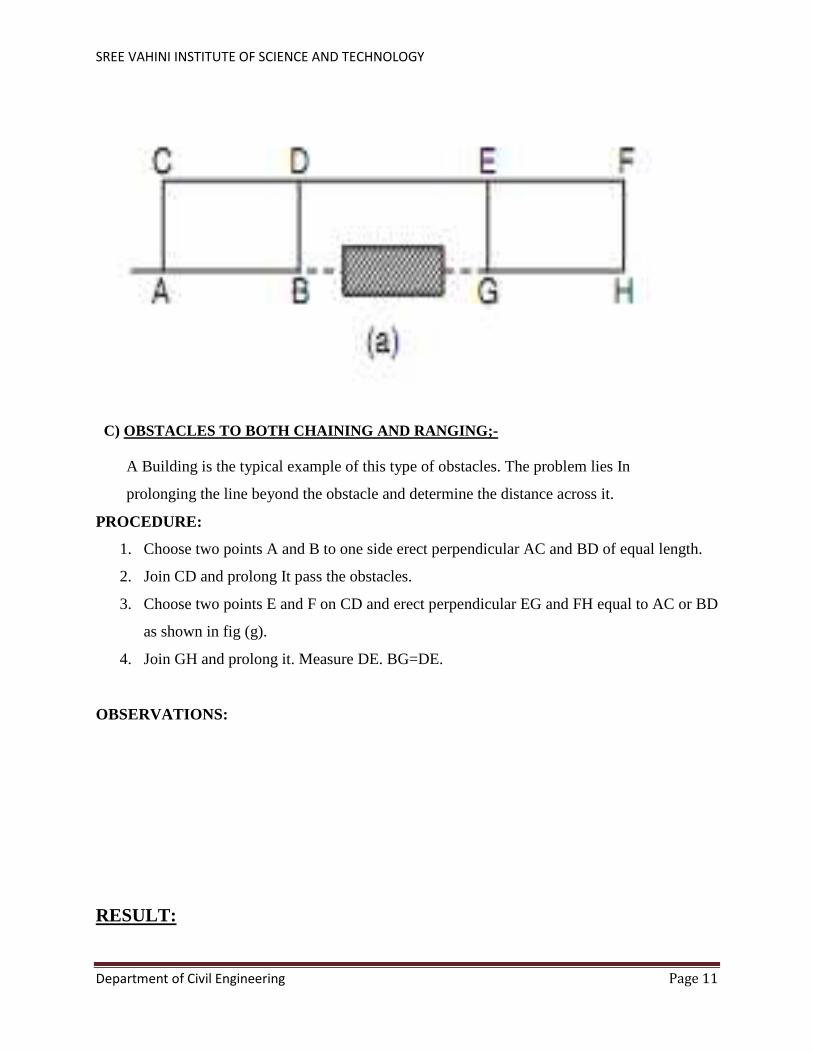
C) OBSTACLES TO BOTH CHAINING AND RANGING;- A Building is the typical example of this type of obstacles. The problem lies In
prolonging the line beyond the obstacle and determine the distance across it.
PROCEDURE:
1. Choose two points A and B to one side erect perpendicular AC and BD of equal length.
2. Join CD and prolong It pass the obstacles.
3. Choose two points E and F on CD and erect perpendicular EG and FH equal to AC or BD
as shown in fig (g).
4. Join GH and prolong it. Measure DE. BG=DE.
OBSERVATIONS:
RESULT:
SREE VAHINI INSTITUTE OF SCIENCE AND TECHNOLOGY
Department of Civil Engineering Page 12
EXPERIMENT NO: 3 DATE:
DETERMINATION OF DISTANCE BETWEEN TWO INACCESSIBLEPOINTS WITH COMPASS.
AIM : To determine distance between two inaccessible points with compass.
EQUIPMENT:
S NO EQUIPMENT QTY 1 Chain 2 Tape 3 Prismatic compass 4 Tripod stand 4 Ranging rods(2mts) 5 Ranging rods(3mts) 6 Arrows
PROCEDURE:
If there is an obstacle between two points say A and B due To which direct distance
measurement is not possible the those points are called As inaccessible points and distance
between them is to be determined indirectly.
1. Let us say the inaccessible distance required is AB fig (a).
2. Select line CD approximately parallel to AB of known length.
3. Place prismatic compass at point C and center it and see to it that is parallel to Ground
surface.
4. Measure bearing of line CA,CB and CD.
5. Then shift compass to point D and in similar way measure bearings of lines DA, DB and
DC from observed bearing.
6. Calculate the interior angles θ1, θ2, θ3, θ4 .from properties of triangle .calculate Angles
θ5 and θ6. Consider Triangle ADC and applying sine rule. We get AC/Sinθ3 =CD/Sinθ5
=AD/Sin (θ1+θ2)
7. Calculate AC and AD.
8. Link wise consider triangle BCD and apply sine rule. BC/Sin (θ3+θ4) =CD/Sinθ6
=BD/Sinθ2 BC and BD.
9. Then consider triangle ABC and apply cosine rule.

SREE VAHINI INSTITUTE OF SCIENCE AND TECHNOLOGY
Department of Civil Engineering Page 13
a. AB=D=√BC²+AC² - 2 X AC X BC X COSθ1.
b. AB=D=√AD²+BD² -2 X AD X BD X COSθ4.

SREE VAHINI INSTITUTE OF SCIENCE AND TECHNOLOGY
Department of Civil Engineering Page 14
EXPERIMENT NO: 4 DATE:
SURVEY OF A GIVEN AREA BY PRISMATIC COMPASS (CLOSED TRAVERSE)
AND PLOTTING AFTER ADJUSTMENT.
AIM: To run a closed traverse by prismatic compass and plot the same.
EQUIPMENT:
S NO EQUIPMENT QTY 1 Chain 2 Tape 3 Prismatic compass 4 Tripod stand 4 Ranging rods(2mts) 5 Ranging rods(3mts) 6 Arrows
DESCRIPTION:
Closed traverse is generally run around a structure .It is defined as a series of connected lines
whose directions and lengths are determined precisely.
PROCEDURE:
Following procedure is adopted to run a closed compass traverse.
1) Let us say we have to run a closed compass traverse ABCDEA.
2) Set the prismatic compass at point A. center it and level it.
3) Take bearings of traverse lines AB and AE.
4) shift the compass to point B center it and level it. Take the bearings BC and BA.
5) Link-wise complete the traverse as shown in fig (a).
6) Measure the length of traverse line AB, BC, CD, DE, and EA.
7) Record the observation in tabular columns.
8) Care must be taken to see that the stations are not affected by local attractions. If they are
affected corrections to local attractions should be applied first and then the traverse should be
plotted with corrected bearings.
9) Simplest method of plotting is angle and distance method with a protractor. If Last point is
falling short by some distance in meeting the first point then it means that there is a closing error.
10) So, traverse should be adjusted by “Bow ditch’s graphical method”.

SREE VAHINI INSTITUTE OF SCIENCE AND TECHNOLOGY
Department of Civil Engineering Page 15
OBSERVATIONS:
LINE LENGTH FORE BEARING BACK BEARING DIFFERENCE
AB
BC
CD
DE
EA
CALCULATIONS:
RESULT:
The adjusted traverse with bearings and length is to be shown on a drawing sheet.

SREE VAHINI INSTITUTE OF SCIENCE AND TECHNOLOGY
Department of Civil Engineering Page 16
EXPERIMENT NO: 5 DATE:
RADIATION METHOD AND INTERSECTION METHOD BY
PLANE TABLE SURVEY
AIM : To locate the details by radiation method and intersection method.
EQUIPMENT:
S NO EQUIPMENT QTY 1 plain table 2 tripod 3 alidade 4 sprit level 5 plumbing fork 6 Chain 7 Tape 8 trough compass 9 Ranging rods(2mts) 10 Ranging rods(3mts) 11 Arrows
PROCEDURE:
RADIATION METHOD:
Suitability:
In this method objects can be located from a single station. In this method rays are drawn from
the single station to objects. The distance from the station to object are measured and plotted to
any suitable scale along the respective rays. This method is suitable for small areas of survey

SREE VAHINI INSTITUTE OF SCIENCE AND TECHNOLOGY
Department of Civil Engineering Page 17
The following is the procedure of radiation method for plane table survey.
1) Select ‘P’ as a station on the ground. 2) From the station ‘P’ the objects A, B, C and D are visible. 3) Set up table over station ‘P’ and level and center. 4) Clamp the table. 5) A point ‘p’ is selected on the sheet to represent the Station ‘P’. 6) With the Trough compass the North line is marked on the right hand top Corner of the
sheet. 7) With the alidade touching ‘p’,the ranging rods A,B,C,and D are bisected and The ray’s
drawn. 8) The distances PA, PB, PC and PD are measured by means of a tape or chain. 9) The distances are plotted to suitable scale to obtain the points a, b, c and d. Representing
the objects A, B, C, and D on the sheet. 10) Suitable scale is chosen based on the length of longest line 11) The method is suitable to locate small defaults 12) The method is suitable to calculate the area of a land.
RESULT:
The result of above method are presented in drawing sheet

SREE VAHINI INSTITUTE OF SCIENCE AND TECHNOLOGY
Department of Civil Engineering Page 18
INTERSECTION METHOD:
Suitability:
In this method Object can be located by Intersections of the Rays drawn from Two Instrument
stations. This method is suitable for locating inaccessible object points. The line joining two
stations is the base line. This method is suitable when it is difficult or impossible to measure
distances As in mountainous area. This method is also used for checking distant objects
PROCEDURE:
1. A and B are two stations and P is inaccessible object on the far bank of a River. 2. Now it is required to locate position of P on the sheet by intersection of rays, drawn
from A and B. 3. Select two stations A and B, so that the P point to be plotted is visible from both A and B
stations. 4. The table is setup at A and levelled. 5. The table is levelled with the help of spirit level and centered by U fork so
that a point ‘a’ on the sheet is just over the station A. 6. The North line is marked on the right side top corner by trough Compass, then table is
clamped 7. With the Alidade touching ‘a’ the ranging rod at B and the object at P are bisected
and rays are drawn through the fiducial edge of Alidade 8. The distance AB is measured and plotted to any suitable scale to obtain the point ‘b’ 9. The table is shifted centered over B and leveled properly . 10. The Alidade touching ‘b’ is placed along the line ‘ba’ 11. Orientation is done by back sighting. At this time it should be remembered
that the centering, leveling and Orientation must be done again if necessary. 12. The Alidade touching ‘b’ the object ‘P’ is bisected and ray is drawn .Let this ray
intersects the previous ray at a point ‘p’ on drawing sheet. 13. This point ‘p’ is the required inaccessible plotted position of ‘P’.
RESULT: The result of above method is presented in drawing sheet.
SREE VAHINI INSTITUTE OF SCIENCE AND TECHNOLOGY
Department of Civil Engineering Page 19

SREE VAHINI INSTITUTE OF SCIENCE AND TECHNOLOGY
Department of Civil Engineering Page 20
EXPERIMENT NO: 6 DATE:
TWO POINT PROBLEM AND THREE POINT PROBLEM BY
PLANE TABLE SURVEY
AIM :
To determine the position, s, of the station S occupied by the plane table, given the accurately
plotted positions, p and q of two points, P and Q, visible from the instrument station and without
occupying these two stations.
EQUIPMENT:
S NO EQUIPMENT QTY 1 plain table 2 tripod 3 alidade 4 sprit level 5 plumbing fork 6 Chain 7 Tape 8 trough compass 9 Ranging rods(2mts) 10 Ranging rods(3mts) 11 Arrows
PROCEDURE:
TWO POINT PROBLEM
Suitability:
The two point problem is a special case of resection to obtain the position of the station occupied
by the table, given the plotted position of two points. The two-point problem can be stated as
follows: to determine the position, s, of the station S occupied by the plane table, given the
accurately plotted positions, p and q of two points, P and Q, visible from the instrument station
and without occupying these two stations.
P and Q are the two survey stations which have been surveyed earlier and their positions plotted
as p and q on the sheet. S is the instrument station (where the plane table is to be set up) and is
required to get the position of S on the sheet as s when the is oriented correctly, i.e., when P-Q is
parallel to p-q.

SREE VAHINI INSTITUTE OF SCIENCE AND TECHNOLOGY
Department of Civil Engineering Page 21
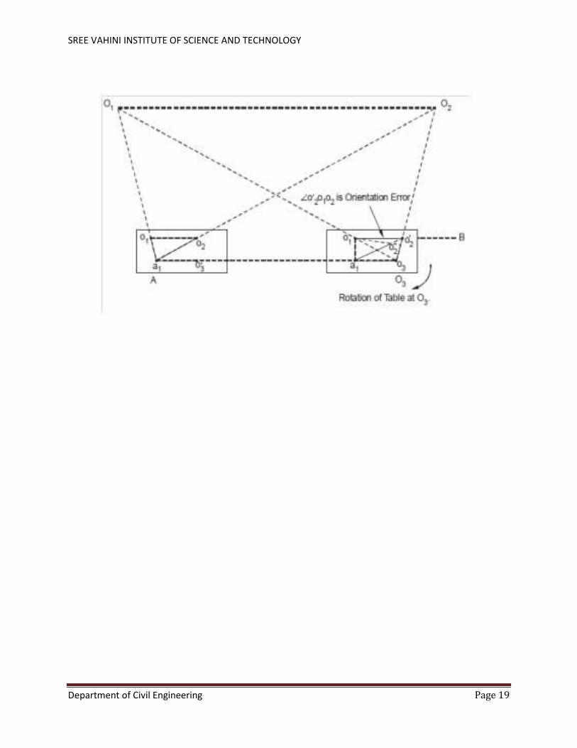
PROCEDURE:
1. Select an auxiliary station R such that the signals at P, Q, and S are clearly visible from R
and the angles formed by P, Q, and S are not very acute.
2. Set up the plane table at R. level the table. Approximately orient the table so the p-q is
nearly parallel to P-Q. Clamp the table in this position.
3. Plot the position of R on the table by sighting to P and Q. for this, keep the alidade
against p and sight the signal at P. Draw a line along the ruling edge of the alidade.
Similarly, sight the signal at Q by pivoting the alidade against q and draw a ray. The
intersection of the two rays drawn gives the position of the station occupied by the table.
Label this point r. point r is a obtained as the position of the station occupied and is
accurate to the extent the line p-q is parallel to P-Q.
4. Transfer the point r on the table to the ground as R using the plumbing fork a peg can be
driven to locate the ground station.
5. With the alidade kept against r, sight the ranging rod or other signal at S and draw a line.
Mark the distance S by approximation or rough chaining. Point s1is thus obtained.
6. Shift the table to S. Level and centre the table over s1. Orient the table by back sighting at
R. For this, keep the alidade against s1and sight the signal at R by rotating the table.
Clamp the table in this position.
7. With the alidade kept against p, sight station P and draw a ray. This ray intersects the line
r-s at s, giving the station s. keep the alidade against s, sight the signals at Q, and draw a
ray. This ray will intercept the ray r-q not at q but q`, as the orientation of the table is only
approximate.
8. P-q` is the presentation obtained of p-q due to the error on orientation. The angle q-p-q` is
the angular error in orientation.
9. To remove this error, place the alidade against p-q` and keep a ranging a rod at a large
distance M.
10. Keep the alidade against p-q and rotate the table until the signal at M is sighted and
clamp the table. This position is the correct oriented position, with P-Q parallel to p-q.
11. Obtained the position of S by sighting P and draw a ray. Keep the alidade against q and
sight the signals at Q. the intersection of the two rays gives the true position, s, of S. the
distance of M must be large enough to correct the orientation of the table.

SREE VAHINI INSTITUTE OF SCIENCE AND TECHNOLOGY
Department of Civil Engineering Page 22
RESULT: The result of above method are presented in drawing sheet
THREE POINT PROBLEM
Suitability:
The three point problem is also a problem of resection. The objective is to obtain
the position of the station occupied by the table after orientation. The three-point
problem can be stated as follows: given three visible stations and their plotted
position, to plot the station occupied by the plane table with the table correctly
oriented with respect to the three points already plotted.
The three point problem can be solved using many methods. The following three
methods will be discussed here.
1. Tracing paper method
2. Graphical method
3. Trial and error method

SREE VAHINI INSTITUTE OF SCIENCE AND TECHNOLOGY
Department of Civil Engineering Page 23
“Trial and error method”
As the name implies, the position of the station occupied is obtained by trial and
error. This is also known as Lehmann’s method. Let P, Q, and R be the ground
stations and p, q, and r be the corresponding plotted positions on the plan. If rays p-
P (keeping the alidade against p, sighting the signal at P, and drawing a line along
the ruling edge), q-Q, and r-R are drawn, they will not coincide at a point as they
should if the table is oriented. The rays will form a small triangle known as the
triangle of error. This triangle can be made smaller and smaller and finally
eliminated by trial and error. Some rules known as Lehmann’s rules are used to
select a new position of the occupied stations as a better choice than that obtained
before. The following procedure is adopted in this method.
PROCEDURE:
1. Set up the level the table at S, the station to be plotted. The three stations, P,
Q, R, must be visible and should not subtend very small angles at S.
2. Orient the table by keeping p-q approximately parallel to P-Q and clamp the
table.
3. Keeping the alidade against the p, set it to sight it sight at P, and draw a ray.
Keep the alidade against q, set the alidade to sight the signal the at Q, and
draw a ray. Keeping the alidade against r, set the alidade to sight the signal
at R and draw a ray. The three rays drawn will not meet at one point, as the
orientation is only approximate. They will form a small triangle of error.
4. To eliminate the triangle of error, select another position of s, the plan
position of the station occupied. Draw the rays s-p, s-q, and s-r. The three
rays will again not meet at a point but will form a smaller triangular of error.
5. The process can be repeated to eliminate the triangle of error.

SREE VAHINI INSTITUTE OF SCIENCE AND TECHNOLOGY
Department of Civil Engineering Page 24
RESULT:
The result of above method are presented in drawing sheet
SREE VAHINI INSTITUTE OF SCIENCE AND TECHNOLOGY
Department of Civil Engineering Page 25
EXPERIMENT NO: 7 DATE:
TRAVERSING METHOD BY PLANE TABLE
SURVEY
AIM:
To run a closed traverse by means of plane table.
EQUIPMENT:
S NO EQUIPMENT QTY 1 plain table 2 tripod 3 alidade 4 sprit level 5 plumbing fork 6 Chain 7 Tape 8 trough compass 9 Ranging rods(2mts) 10 Ranging rods(3mts) 11 Arrows
Suitability:
This method is suitable for connecting the traverse stations. This method is
similar to compass traversing or theodolite traversing. In this method the plane
table set up at each successive station. It is used for running survey line between
stations to locate the topographical details.
PROCEDURE:
1) The alidade touching the point ‘a’ and sighting the ranging rod at ‘B’, is
bisected and ray is drawn.
2) The distance ‘AB’ is measured and plotted to suitable scale.
3) The table is shifted and centered over ‘B’ station.
4) It is then levelled oriented by back sighting and clamp the table.
5) With the alidade touching point ‘b’, the ranging rod at ‘C’ is bisected and a ray
is drawn.

SREE VAHINI INSTITUTE OF SCIENCE AND TECHNOLOGY
Department of Civil Engineering Page 26
6) The distance BC is measured and plotted to same scale.
7) The table is shifted and set up at C and the same procedure is repeated.
8) In this manner, all the stations of the traverse are connected.
Note:
At the end the finishing point may not coincide with the starting point and there
may be some closing error.
RESULT:
The result of above method are presented in drawing sheet
.
EXPERIMENT NO: 8 DATE:

SREE VAHINI INSTITUTE OF SCIENCE AND TECHNOLOGY
Department of Civil Engineering Page 27
FLY LEVELING (DIFFERENTIAL LEVELING).
Aim: To find the difference in elevation between two points. Instruments: 1. Dumpy level
2. Leveling staff
Figure: Procedure: 1. Let A and B be the two given points whose difference is elevation is to be found. 2. Set the level at convenient point O1 carryout temporary adjustments and take B.S on A 3. Take FS on the Point C 4. Shift the instrument to point O2 and perform temporary adjustments. 5. Take B.S on C. 6. Take F.S. on D. 7. Shift the instrument to point O3 and perform temporary adjustments. 8. Take B.S on D 9. Take F.S on B. 10. Find the difference in elevation between A and B by both the methods. Result: Difference in elevation between A and B = ……………
EXPERIMENT NO: 9 DATE:
LONGITUDINAL SECTION AND CROSS SECTION

SREE VAHINI INSTITUTE OF SCIENCE AND TECHNOLOGY
Department of Civil Engineering Page 28
Aim:- L-Section and cross section of the road
Apparatus required: -
• Dumpy level
• Leveling staff
• Ranging rod
• Tape
Theory:-
Profile Leveling:-
The process of determining elevations at points at short measured
intervals along a fixed line is called Longitudinal or profile leveling.
Cross Sectioning:-
It is a method of leveling to know the nature of Ground on either side of
the centerline of the proposed route. Levels are taken at right angles to
the proposed Direction of the road end at suitable distances and leveling
is carried out along this cross Section.
During location and construction of highways, Rail tracks sewers
and canals strakes or other marks are placed at various aligned points
and the undulation of the ground surface along a predetermined line is
adjoined. The line of section may be single straight lines changing
directions.
SREE VAHINI INSTITUTE OF SCIENCE AND TECHNOLOGY
Department of Civil Engineering Page 29
Levels are taken at right angles to the proposed Direction of the road end at
suitable distances and leveling is carried out along this cross section. Cross section
are the sections run at right Angles to the centerline and on the either side of it for
the purpose They are taken at each 10,m station on the centerline. The length of
Cross section depends upon the nature of the work if cross sections are Short they
are set square out by edge. If long they are set out by the Optical square, box
sextant or theodolite. They are serially numbered from the beginning of the
Centerline and are taken simultaneously with the longitudinal section they may be
taken at the hand level, level, abney level or theodolite.
Procedure:-
Let ABC be the line of section set out on the ground and marked with pegs driven
at equal interval (say 20m to 30m) as in the figure. The level is set up generally on
one side of the profile to avoid too short sight on the points near the instrument and
care is taken to set up the level approximately midway between two change points.
The leveling is started from the bench mark of known value. From each set up staff
reading are taken on pegs already fixed at the desired interval and also at
significant points where about changes of slope etc. occur.
All these readings are recorded as intermediate slight against the respective
chain ages along the line in the level book. Other data of the level book is also
filled up before starting the work. When the length of sight is beyond the power of
the telescope (usually it is 100m), the foresight on the change point is taken. The
level is then is then shifted and setup in an advanced position and a back sight is
taken on the change point. The change point may or may not lie in the line of
section. Chaining and reading are then continued as before, till the whole line of
section is completed. The work is to be checked in the progress of leveling by
taking reading on other bench marks, on the way or on bench marks fixed by
differential leveling. The fore and back bearing of the section line should betake

SREE VAHINI INSTITUTE OF SCIENCE AND TECHNOLOGY
Department of Civil Engineering Page 30
and recorded. Next sketches of the bench mark, change points, and other feature
such as nallah, a road, canal, etc. crossing the section line be drawn and fully
described in the remarks column of the level-book. The procedure and
corresponding reading and values are represented on the page of a level-book for a
part of road project.
Plotting The Longitudinal Section:-
Level Book:-

SREE VAHINI INSTITUTE OF SCIENCE AND TECHNOLOGY
Department of Civil Engineering Page 31
Whenever leveling operation is carried out the staff reading taken in the field is
entered in the note book called a Level-Book. Each page of it has the following
columns which help in booking of reading and reduction of levels.
Result:-
Thus the longitudinal section and cross section of road was plotted and readings
are noted in the page level book.
EXPERIMENT NO: 10 DATE:
CONTOURING

SREE VAHINI INSTITUTE OF SCIENCE AND TECHNOLOGY
Department of Civil Engineering Page 32
Aim: - Contour plan of given area
Apparatus:-
• Dumpy level
• Prismatic compass
• Chain 20m, 30m
• Metallic Tape
• Ranging rod
• Leveling staff
• Pegs line.
Theory:-
Contouring:-
The elevation and depression the undulations of the surface of the ground are
shown as map by interaction of level surface with by means of contour line. a
contour may be defined as the line of intersection of a level surface with the
surface of the ground. Characteristics of Counter Lines The following are the
Characteristics of the contours/ contour lines.
• All points on the same contour line will have the same elevation.
• Contour lines close together represent steep ground, while uniform slope is
indicated when they are uniformly spaced. A series of straight, parallel and
equally spaced contours show a plane or flat surface.
• Contour lines of different elevation cannot merge or cross one another on the
map, expect in the case of an overhanging cliff. A vertical cliff is indicated
when several contours coincide.
• A contour line must close upon itself either within or without the limits of
the map.

SREE VAHINI INSTITUTE OF SCIENCE AND TECHNOLOGY
Department of Civil Engineering Page 33
• Series of closed contour lines on the map either represent a hill or a depression according as the higher or lower values are inside them as shown below.
• A contour will not stop in the middle of the plan. It will either close or go out of the plan.
• Ridge or water shad and valley lines are the lines joining the top most or the
bottom most points of hill and valley respectively, cross the contours at right
angles. A ridge line is shown when the higher values are inside the loop,
while in the case of a valley line, the lower values are inside the loop as
shown in fig (1.3)

SREE VAHINI INSTITUTE OF SCIENCE AND TECHNOLOGY
Department of Civil Engineering Page 34
• Contour lines are not drawn across the water in the stream or river because
the water level in that is not constant; but contours are drawn along the bed
of a river or a stream.
Uses of contour map:-

SREE VAHINI INSTITUTE OF SCIENCE AND TECHNOLOGY
Department of Civil Engineering Page 35
• For preparing contour map in order to select the most economical or a
suitable site
• For getting the importance about ground whether it is undulating or
Mountainous
• To locate the alignment of canal so that it should follow a ridge line, thus
canal construction will be economical and will command maximum irrigated
area.
• To make the alignment for the road, railway so that the quantity of
earthwork both in cutting and filling should be minimum.
• To find out the capacity of the reservoir or a volume of earthwork especially
in the Mountainous region.
• For preparing contour map in order to select the most economical or suitable
site.
• As its definition itself indicates the line joining the points of same elevation
that means it naturally prefers the condition of nature of ground itself.
• It is also used for irrigation purpose as from it capacity of reservoir.
Locating Contours:-

SREE VAHINI INSTITUTE OF SCIENCE AND TECHNOLOGY
Department of Civil Engineering Page 36
By cross-section method:-
This method is commonly used in rough survey, cross sections are run traverse to the contour line of road, and railway as canal and the point of change of slope (representations) are located. The cross-section line may be inclined at any angle to the centerline if necessary. The spacing of the cross sections depends upon the characteristics of the ground. By interpolation of contour is meant the process of spacing the contour proportioning between the plotted ground points. Contour may be interpolated by
1. Estimation
2. Arithmetical calculations
3. Graphical method .in all these methods
It is assumed that the slope of the ground between any two random points is
uniform.
Result: - Thus the contour of given area is drawn in the sheet.