surprise-1 re-entry well completion report...
TRANSCRIPT

SURPRISE-1 Re-Entry
WELL COMPLETION REPORT
(Basic)
EP 115
Amadeus Basin
Northern Territory
11th
Nov. – 20th
Dec. 2011
Central Petroleum Limited

Well Name: Surprise-1 Re-Entry
Well Classification: Exploration
Interest Holders: Central Petroleum Limited (Operator - 100%)
Petroleum License: EP 115, Northern Territory
Location: Northing: 7377073m
Easting: 601261m
Latitude: 23º 42’ 50.758S” South
Longitude: 129º 59’ 36.091”E East
Australian Map Grid Zone : GDA 94, Zone 52
Ground Level (GL): 545m ASL
Kelly Bushing (KB): 548.7m ASL - Datum
Total Depth (KB): 2732m MD RKB
Drilling Contractor: Hunt Energy
Drilling Rig: Hunt Rig 3 (See Rig Specifications in Appendix 9)
Contractors: Drilling Fluids: Australian Mud Company
Mud Logging: Geoservices
Wireline Logging: Schlumberger
Cementing: Trican
Casing: Premium Casing Services
MWD: PathFinder Schlumberger
Directional Drillers: Pathfinder Schlumberger
Spud Date: 19th
November 2011
Total Depth Reached: 30th
November 2011
Rig Released: 20th
December 2011
Well Status: Cased/Plugged and Side-tracked.

Table of Contents
1.0 Introduction and Summary 5
2.0 General Data 7
3.0 Drilling 8
3.1 Summary of Drilling and Related Operations 8
3.2 Particulars of Drilling 8
3.2.1 Particulars of the equipment installed in/or on the well 8 3.2.2 Casing strings in situ/run. 9 3.2.3 Cementing operations 11
3.2.4 Bit Records 11 3.2.5 Deviation Surveys 11 3.2.6 Drilling Fluids 11
3.2.7 Lost Time 12
3.2.8 Water Supply 12
4.0 Logging, Sampling and Testing 13
4.1 Cuttings Samples Inventory 13
4.2 Conventional Cores 13 4.3 Sidewall Cores 13 4.4 Mudlogging 13
4.5 Wireline Logging 14
4.6 Vertical Seismic Profile 14 4.7 Drill Stem Testing 14
5.0 Geology and Formation Evaluation 15
5.1 Regional Geological Setting and Discussion of the Surprise Prospect 15
5.1.1 Structural Elements 15 5.1.2 Lithology and Formation Tops 16 5.1.3 Undifferentiated Recent Alluvium and Pertnjara Group 17
5.1.4 Brewer Conglomerate/Hermannsburg Sandstone 18 5.1.5 Parke Siltstone (mid Devonian) 18
5.1.6 Mereenie Sandstone (early Devonian) 18
5.1.7 Stokes Siltstone (late Ordovician) 18
5.1.8 Upper Stairway Sandstone (Early Ordovician) 19 5.1.9 Middle Stairway Sandstone (Early Ordovician) 19 5.1.10 Lower Stairway Sandstone (E Ordovician) 19 5.1.11 Horn Valley Siltstone (Early Ordovician) 20 5.1.12 Pacoota Sandstone (Early Ordovician) 21
5.2 Hydrocarbon Indications and Sample Analysis 21
5.2.1 Gas while drilling 21 5.2.2 Fluorescent Hydrocarbon Shows 22
6.0 Reference 23
Tables Table 1: Surprise-1 Re-Entry Well Index Sheet .............................................................. 7
Table 2: Surprise-1 Re-Entry Formation Tops Actual / Predicted. ............................... 16
Figures Figure 1: Surprise-1 Re-Entry Location and Permit Map ................................................ 5
Figure 2: Surprise-1 Re-Entry Location and Seismic lines Map ..................................... 6
Figure 3: Surprise-1 Re-Entry Status Diagram .............................................................. 10
Figure 4: Surprise-1 Re-Entry Time Delays .................................................................. 12
Figure 5: Amadeus Basin structural elements map ........................................................ 15
Figure 6: Cross Section Surprise-1 Re-Entry to Johnstone West-1 ............................... 16
Appendices 1. Daily Drilling Reports
2. Daily Geological Reports
3. Cuttings Descriptions
4. Wireline Logs
5. Bit records
6. Vertical Seismic Profile – Results
7. Drilling Fluid Recap, RMS Pty Ltd
8. Mudlog data and plot.
9. Rig Specifications

1.0 Introduction and Summary
Surprise-1 Re-Entry was drilled by Central Petroleum Ltd in Exploration Permit EP 115 in the
western part of the Amadeus Basin, Northern Territory, approximately 400km west of Alice
Springs location map (Figure-1). The well was spudded on 19th
October 2011 and reached TD of
2732m on 11th
December 2011. It was cased and abandoned below the 95/8” casing for side-track
to drill a horizontal well targeted at a new location on the structure based on wireline logs
evaluations suggesting possible formation damage around the wellbore.
Figure 1: Surprise-1 Re-Entry Location and Permit Map
The aim of Surprise-1 Re-Entry was to re-test the hydrocarbon potential of a salt cored anticlinal
structure mapped at the Pacoota and Stairway sandstones, with primary focus on the potential
reservoir zone identified in the cored section of the Lower Stairway sandstone. A secondary aim
was to core the shales of the Horn Valley siltstone, a sequence that separates the Pacoota and
Stairway sandstones, in order to obtain information regarding the potential shale gas in this area
through desorption testing. Evaluation of deeper reservoirs in the Pacoota sandstone was an
optional third objective. Basic well results are summarised in the Well Index Sheet (Table-1).
Surprise-1 Re-Entry
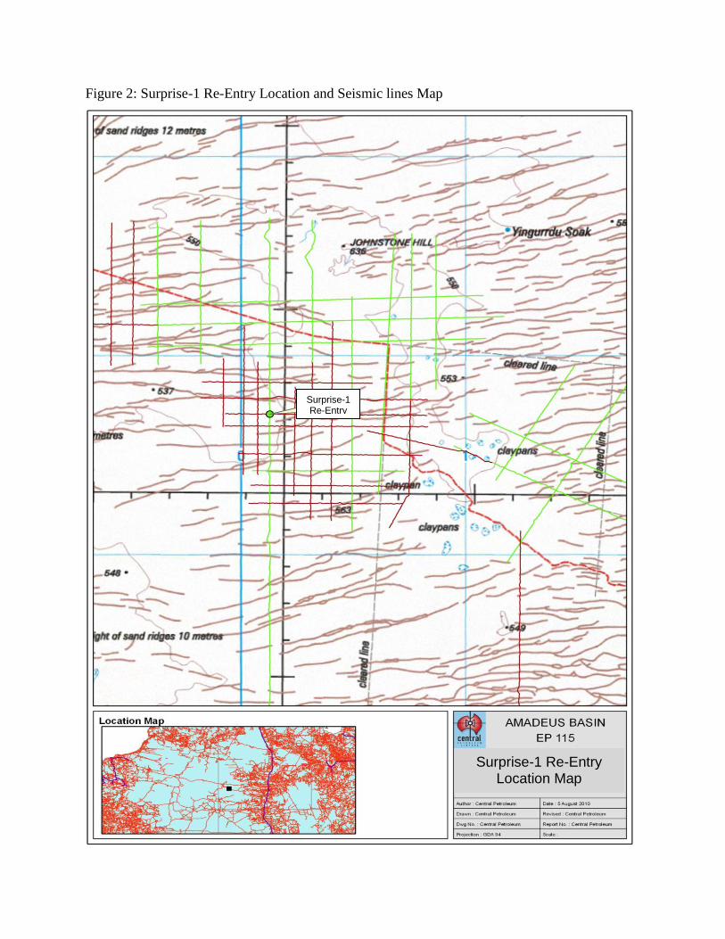
Figure 2: Surprise-1 Re-Entry Location and Seismic lines Map
Surprise-1 Re-Entry
Surprise-1 Re-Entry Location Map

2.0 General Data
Table 1: Surprise-1 Re-Entry Well Index Sheet
WELL NAME: Surprise-1 Re-Entry
OPERATOR: Central Petroleum Limited CLASSIFICATION: Exploration Re-entry
Location: Latitude: 23º 42’ 50.758”S
Longitude: 129º 59’36.091”E
GDA 94 Zone 52
Rig Details:
Rig Name: Hunt Rig#3
Contractor: Hunt Energy
Rig Type: Land D-E SCR
Dates: Spud Date: 19
th Nov. 2011
TD Date: 30th
Nov. 2011
RE HST1: 21st Dec. 2011
Basin: Amadeus
Field: Wildcat
Permit: EP-115, Northern
Territory, Australia
Depths: Surface Elevation (ASL): 545m
Rig Datum, KB : 3.7m AGL
Total Depth: 2732m MD
Status: Cased/Plugged and Side-tracked.
Casing/Liner Details: Size Depth
20”Conductor 21.3m
13⅜” 493.82m
9⅝” 1443.4m
7 “ 2729.2m
Mud Details: Mud Type:
Fresh water + KCL polymer mud
(8.8 - 9.2 ppg = 1.05 – 1.1 sg)
2555 – 2732m.
Trajectory:
Vertical (3 deg. @ TD).
Coring Details: None
Sidewall Cores:
None
Cuttings Interval Sample Rate 2553 – 2732 m 3m
FORMATION MD
KB (m)
TVD
KB (m)
Isopach
TVD (m)
SubSea
TVD (m)
TWT
msec Comments
Undiff. Recent alluvium
Undiff. Pertnjara Group
Brewer/Hermannsburg
Parkes Siltstone
Mereenie Sandstone
Stokes Siltstone
Upper Stairway Sst
Mid Stairway Sst
Lwr Stairway Sst
Horn Valley Siltstone
Pacoota Sandstone
Total Depth
3.7
70
780
1296
1760
2275
2447
2475
2542
2561
2613
2732
3.7
70
780
1295.6
1757
2270
2442.7
2486.5
2538
2557
2608.5
2728.5
66.3
710
515.6
461.4
513
172.7
43.8
51.5
19
51.5
545
478.7
-231.3
-746.9
-1208.3
-1721.3
-1894.0
-1937.8
-1989.3
-2008.3
-2059.8
Nd*
Nd
100.6
319.6
506.6
742.7
811.5
822.0
854.0
861.4
881.9
Recent-Quaternary
Mid- Late Devonian
Mid Devonian
E Devonian
Sil-E Devonian
Late. Ordovician
E. Ordovician
E Ordovician
E Ordovician
E. Ordovician
E. Ordovician
LOGGING
Date Depth (m)
Description Remarks From To
4.12.2011 2725 1446 HRLA-PEX-HNGS GR to surface
4.12.2011 2725 1446 FMI-ECS-DSI
6.12.2011 2447.5 2547.3 MDT Cable stuck, tool fished
12.12.2011 2720 100 VSIT (Check shot) 42 levels

3.0 Drilling
3.1 Summary of Drilling and Related Operations
The original Surprise-1 well that was suspended after the accident on the MB Century Rig 7 in
December 2010, was planned to be re-entered and side tracked using the bottom most cement
plug. Fresh formation was then to be drilled vertically and tested which included the Lower
Stairway sandstone, Horn Valley siltstone, Pacoota sandstone and the Goyder Formation.
The Hunt Rig #3 was mobilized to location and the well was re-entered on 19th
November 2011.
The first cement plug and the Halliburton bridge plug were drilled out from 100m to 131.9m
MDRT. The bit was then RIH down to the 2nd
cement plug at 1378m MDRT, above the 9 5/8”
casing shoe. Prior to drilling out the plug, the casing integrity was pressure tested to 3000 psi.
Once the 2nd
cement plug was drilled out, the 8 ½” open hole was reamed and washed down to
the top of the 3rd
cement plug at 2297m MDRT. The assembly was POOH and the draw-works
brakes had to be repaired due to damage from driller error. The BOPs were tested as per weekly
schedule.
It was then decided instead of side-tracking the well, the original borehole below the cement plug
would be re-entered and evaluated prior to consideration being given to side-track the well. The
drilling assembly was then RIH but later tripped out due to obstruction. The mud line also had to
be repaired with a temporary installation. The drilling assembly was RIH and the tight spots
washed and reamed to the top of the 3rd
cement plug.
After the 3rd
cement plug was drilled out, the hole was washed and reamed down to the
suspended depth of 2555m MDRT. The well was then deepened to a TD of 2732m MDRT
penetrating the Horn Valley siltstone and Pacoota sandstone. The Goyder Formation was not
intersected as planned due to limitations in rig capability.
Open hole wireline logging was conducted as specified in Section 2.0 of this report. However
during the MDT run, due to hole rugosities, the MDT tool got stuck. The tool was successfully
fished by using the cut and thread method. The BOPs were then tested and the checkshot survey
was conducted.
Initial log interpretation results had indicated that the Lower Stairway sandstone was prospective
and the Pacoota sandstone was water wet. It was thus planned to run and cement 7” casing to TD
and then drill a horizontal leg in the Lower Stairway sandstone. A whipstock was set in the 7”
casing at 2423m MDRT in preparation to kick off the well.
The daily drilling reports are provided in Appendix 1.
3.2 Particulars of Drilling
3.2.1 Particulars of the equipment installed in/or on the well
Other than casing, there is no other equipment that is installed in the well.

3.2.2 Casing strings in situ/run.
Conductor Casing
- 20” conductor casing in situ at 21.3m MDRT.
Surface Casing
- 13 3/8” surface casing in situ at 493.8m MDRT.
Intermediate Casing
- 9 5/8” intermediate casing in situ at 1,443.44m MDRT.
Production Casing
- 7” production casing run and set at 2729.2 m MDRT.
Plugged/Side-track
A whipstock was set in the 7” casing at 2423m MDRT in preparation to mill a window to kick
off the well.

Figure 3: Surprise-1 Re-Entry Status Diagram
8-1/2" Rathole
Previous TD 2,555m
TD @ 2,750m
9-5/8" Csg 1,450m
Cement to Surface
20" Csg 30m
Cement to surface
Surprise-1 Re-entry
8-1/2" OH
Cmt. Plug #2 @ 1,415m to 1,475m
Cmt.Plug #3 @ 100m to 130m
Cmt. Plug #1 @ 2,310m to 2,360m
0 m
760 m
1291 m
1763 m
2277 m
2445 m
2612 m
2902 m
Undifferentiated
Surficial Sediments
Stokes Sltst
Horn Valley Sltst
Pacoota Sst
Brewer Conglomerate
Parke Sltst
Mereenie Sst
Stairway Sst
2562 m
Surface Depths
W/Line BP #1 @ 130m
MU
DG
EL
SW
EE
PS
1300m
1450m
13-3/8 Csg 500m
Cement to Surface
7" Production Liner
Cement to surface
*Shoe set at 2,750m
3076 m
3355 m
Goyder Fm
Top Salt
Legal Notice: This is a pictorial representation only and is subject to ongoing review and modification as new data is received
and analysed. Dependent on results the well may be drilled to a total depth less than 3,355m. Completion for production is
contingent upon successful evaluation.

3.2.3 Cementing operations
The only cementing operation was performed on the 7” casing as described below:
Production Casing: An 8 ½” hole was initially drilled to 2,555m MDRT which was then
deepened to 2,732m MDRT in the re-entry. The 7” 26ppf N-80/L-80 BTC and 29ppf L-80 BTC
production casing was cemented in place with 12.8ppg lead cement consisting of 155 sacks of
Class G cement. This was followed by 15.6ppg tail cement consisting of 353 sacks of Class G
cement. The plug was bumped at 3,000psi. There were 3bbls of cement returns.
3.2.4 Bit Records
A record of drilling bits used on Surprise 1 Re-Entry is presented in Appendix 5.
3.2.5 Deviation Surveys
Deviation surveys were taken using a Totco survey tool. No survey results were recorded due to
miss run.
3.2.6 Drilling Fluids
9 5/8” Casing, 0 – 1447m MDRT
Gel Sweeps
Mud weight was kept between 8.55 – 8.9ppg to the top of 2nd
cement plug. Gel sweeps were run
to assist with cleaning out the drilled cement.
8 ½” Production Hole, Original Hole, 1,447m – 2,555m MDRT
KCl Mud
Mud weight was kept between 8.7 – 8.95ppg to the base of the suspension depth, 2,555m
MDRT. This mud was contaminated with the suspension mud left in the original borehole since
December 2010.
8 ½” Production Hole (new hole), 2,555m – 2,732m MDRT
Residrill Mud
The new and old KCl mud was circulated out from the bore hole. This mud was replaced with
new Residrill mud which was aimed at reducing formation damage. Mud weight was kept
between 8.75 – 9.1ppg. API fluid loss had been reduced with this mud type to reduce filtrate
invasion.
The details of daily record of drilling fluid properties are provided in Appendix 7.
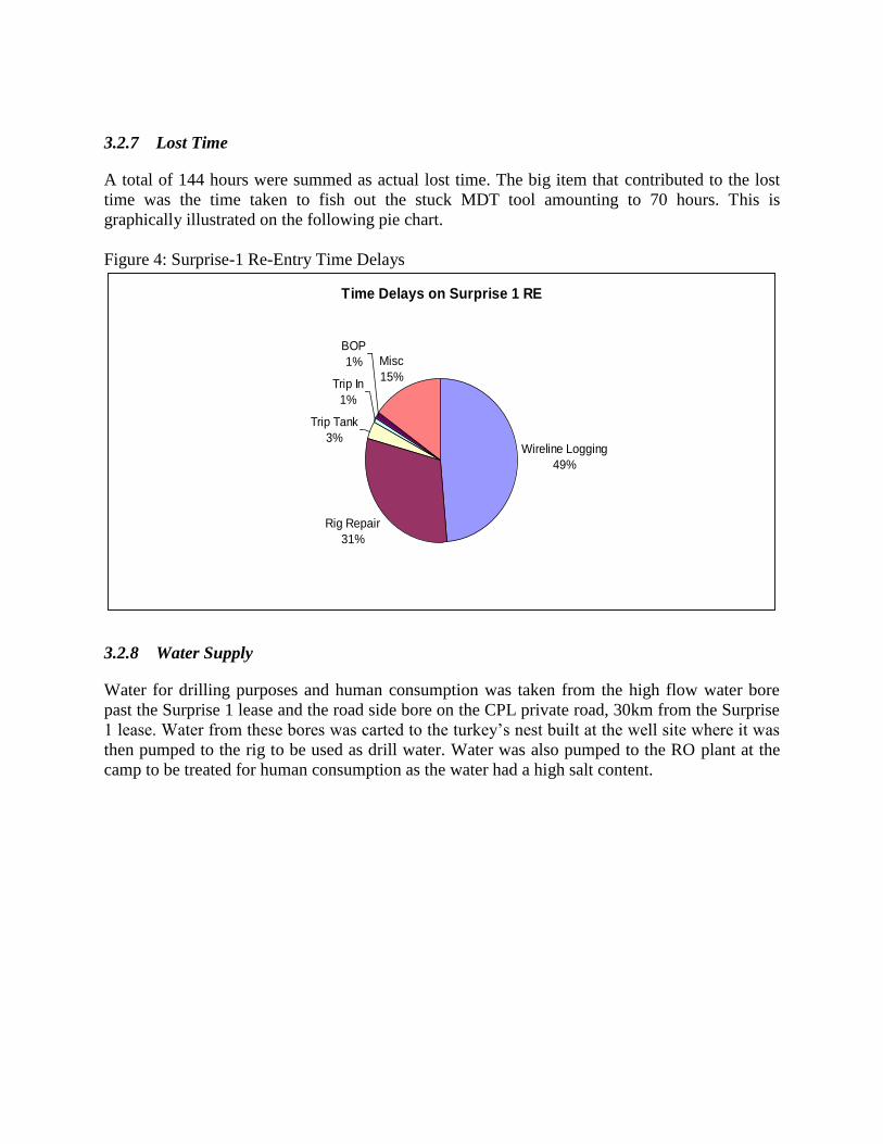
3.2.7 Lost Time
A total of 144 hours were summed as actual lost time. The big item that contributed to the lost
time was the time taken to fish out the stuck MDT tool amounting to 70 hours. This is
graphically illustrated on the following pie chart.
Figure 4: Surprise-1 Re-Entry Time Delays
Time Delays on Surprise 1 RE
Wireline Logging
49%
Rig Repair
31%
Trip Tank
3%
Trip In
1%
BOP
1% Misc
15%
3.2.8 Water Supply
Water for drilling purposes and human consumption was taken from the high flow water bore
past the Surprise 1 lease and the road side bore on the CPL private road, 30km from the Surprise
1 lease. Water from these bores was carted to the turkey’s nest built at the well site where it was
then pumped to the rig to be used as drill water. Water was also pumped to the RO plant at the
camp to be treated for human consumption as the water had a high salt content.

4.0 Logging, Sampling and Testing
4.1 Cuttings Samples Inventory
Sample type Interval mRT Frequency
B (Bulk unwashed) 2563 – 2613 m Spot+composites
F (Fluids) Whilst circulating Spot as required
G (Gas bag -Tedlar) On Gas peaks 3 x 1 litre volume
S (Samplex trays) 2553 m – 2732 m MD 3 m (15 m per tray)
W (Washed & air dried) 2553 m – 2732 m MD 3 m (2 sets)
Samples were distributed as follows:
Type B: to CTP Perth for selective HC / source rock analysis.
Type F: to Weatherford Labs Perth for HC fluids analysis.
Type G: to Bureau Veritas Adelaide for full spectrum HC Chromatogram plus He.
Type S: to CTP Geology Perth
Type W: to CTP Warehouse Alice Springs thence 1 x set to CTP Perth, 1 x set to NTDME.
4.2 Conventional Cores
No cores were cut in Surprise-1 Re-Entry.
4.3 Sidewall Cores
There were no sidewall cores taken in Surprise-1 Re-Entry.
4.4 Mudlogging
Mudlogging services were contracted to Geoservices who supplied a Standard Unit module
monitoring drilling parameters, continuous gas monitoring, pit levels, cuttings sampling and
bagging. 4 x remote VDUs serviced the Drill floor, Tool pusher, Company man and Well-site
Geologist with real time drilling data. Daily reports and Mudlogs were supplied to Central
Petroleum onsite and Perth office. The final Mudlog and gas datasheets are contained in
Appendix 8.
4.5 Wireline Logging
Schlumberger Australia supplied Unit 1909 (offshore modules) with 2 x full crews plus MDT
technician.
The logging suite was revised from earlier programs dropping the planned MSCT (Run 5) and
removing the Cross Dipole Sonic configured for Run 2. The final log suites are presented in
Appendix 4.
Run #1 : Super Combo HRLA-PEX-HNGS
Run #2 : FMI-DSI-ECS-GR
Run #3 : MDT (38 Pre-test, plus 12 x 450 ml samples, 2 x 3.78 litre chambers)
Run #4 : Check shot/VSI (42 levels)
Run #1 refined the known HC zone in the Lower Stairway Sandstone and QL interpretations
indicated a possible 8 metre pay zone straddling the cored section, with a possible OWC at
2551m.
4.6 Vertical Seismic Profile
A Check shot survey was conducted by Schlumberger Wire line services. A total of 42 levels
were recorded, the survey data and report in Appendix 6.
4.7 Drill Stem Testing
No drill stem tests were conducted.
5.0 Geology and Formation Evaluation
5.1 Regional Geological Setting and Discussion of the Surprise Prospect
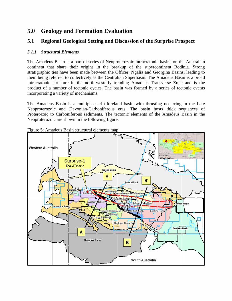
5.1.1 Structural Elements
The Amadeus Basin is a part of series of Neoproterozoic intracratonic basins on the Australian
continent that share their origins in the breakup of the supercontinent Rodinia. Strong
stratigraphic ties have been made between the Officer, Ngalia and Georgina Basins, leading to
them being referred to collectively as the Centralian Superbasin. The Amadeus Basin is a broad
intracratonic structure in the north-westerly trending Amadeus Transverse Zone and is the
product of a number of tectonic cycles. The basin was formed by a series of tectonic events
incorporating a variety of mechanisms.
The Amadeus Basin is a multiphase rift-foreland basin with thrusting occurring in the Late
Neoproterozoic and Devonian-Carboniferous eras. The basin hosts thick sequences of
Proterozoic to Carboniferous sediments. The tectonic elements of the Amadeus Basin in the
Neoproterozoic are shown in the following figure.
Figure 5: Amadeus Basin structural elements map
Surprise-1 Re-Entry

Figure 6: Cross Section Surprise-1 Re-Entry to Johnstone West-1
5.1.2 Lithology and Formation Tops
Table 2: Surprise-1 Re-Entry Formation Tops Actual / Predicted.
Formation Top
Actual Prognosis
Depth
KB (m)
Depth
GL(m)
Isopach
(m)
TVDSS
(m) TVDSS
(m)
TVDR
(Tm)
Hi/Lo
(m)
Undiff. Surficial Sediments 3.7 0 66.3 +545 550 3.7 -
Undiff Perthjara Gp 70 66.3 710 +478.7 -
Brewer / Hermannsberg 780 776.30 515.6 -231.3 -210 760 21.3 L
Parkes Siltstone 1296 1292.3 461.4 -746.9 -754 1304 7.1 H
Mereenie Sandstone 1760 1756.3 513 -1208.3 -1234 1784 25.7 H
Stokes Siltstone 2275 2771.3 172.7 -1721.3 -1901 2451 179.7 H
Upr Stairway Sandstone 2447 2443.3 43.8 -1894.0 -2031 2581 137.0 H
Mid Stairway Sandstone 2493 2471.3 51.5 -1937.8
Lwr Stairway Sandstone 2543 2538.3 19 -1989.3
Horn Valley Siltstone 2561 2557.3 51.5 -2008.3 -2106 2656 97.7 H
Pacoota Sandstone 2613 2609.3 -2059.8 -2144 2694 84.2 H
Goyder Formation Np -2416 2966
Total Depth 2732 2738.3 -1130.5 Elevations: GL 545m ASL, KB 3.7m AGL. Depths are driller’s from mudlog. Np (Not penetrated).

NOTE: Lithology summaries to base Lower Stairway Sandstone are extracted from Surprise-1
Well Completion Report.
5.1.3 Undifferentiated Recent Alluvium and Pertnjara Group
5.2-70m
This section comprised Aeolian alluvium down to 70m. This is essentially the Quaternary to
Recent dune deposits seen at surface, comprising white to light grey quartz grains stained
yellow-orange and common reworked grey brown siltstone grains. The grains are fine to coarse
and rounded, sub-spherical and frosted. There are abundant composite grains of quartz sand and
siltstone grains weakly bound with yellow-orange iron oxide cement. Many grains are irregular
and broken indicating it is possibly pebbly. Gypsum appeared in the form of white to off-white,
chalky, soft material. It is occasionally micro to coarsely crystalline and abundant in parts,
commonly with a vuggy porosity possibly after halite crystals. It is probably distributed as
nodular clumps, and often exposed at the surface in that manner.
70-230m Firm bedrock was observed at 70m in the form of weathered arkosic sandstone. It is white to
light grey, dark brown grey where silty and argillaceous, friable to firm, fine to coarse, sub-
angular to sub-rounded, moderately sorted, with occasional pebbly conglomeratic lags. It is
slightly calcareous and carbonaceous with common kaolin and mica flakes and lithic grains.
Porosity is poor to fair. This is variably interbedded with claystone and siltstone and becomes
predominantly interbedded sandstone and siltstone with depth.
The claystone is medium red brown, mottled greenish grey in parts, soft to firm, blocky, silty and
micaceous. The siltstone is similar being medium to dark red brown, soft, blocky to sub-fissile,
very argillaceous and very micaceous.
230-780m This is predominantly a siltstone sequence with various thin interbeds of sandstone, claystone
and gypsum.
The siltstone is medium grey brown to dark grey, soft to hard, generally blocky, argillaceous and
sandy, grading to very fine sandstone in parts. It is micaceous and occasionally gypsiferous with
occasionally carbonaceous laminae and coarse sandy lamination.
Sandstone is generally light brown to light grey with clear to translucent white quartz grains,
loose to friable, fine to very coarse, predominantly medium grained, sub-angular to rounded and
poorly sorted. Grains are commonly frosted. It is slightly calcareous, with argillaceous and silty
matrix, traces of mica and traces of crystalline pyrite. Porosity is generally poor. The claystone is
light to medium grey, soft, blocky, silty, and micro-micaceous with traces of carbonaceous
specks. Gypsum occurs as white chalky nodular material and coarsely crystalline fibrous
material.
5.1.4 Brewer Conglomerate/Hermannsburg Sandstone
780-1296m This section is stratigraphically part of the Pertnjara Group and is essentially similar to the
overlying units. It comprises predominantly siltstone with thin sandstone and claystone interbeds
and intergradations and minor limestone interbeds. The siltstone is medium brown to dark grey
brown, firm to hard, blocky, argillaceous, sandy, and slightly calcareous with common dark mica
flakes. Sandstones are light grey green and dark brown, translucent in parts, loose to friable and
hard in parts, very fine to coarse, predominantly fine, sub-angular to rounded, poorly to
moderately sorted, silty, argillaceous, slightly calcareous, with traces of feldspar grains, mica and
microcrystalline pyrite. Porosity is generally very poor. Claystones are light grey, light yellowish
brown and dark brown in places, soft to firm, blocky, silty, micro-micaceous, calcareous in parts
and occasionally with traces of gypsum.
5.1.5 Parke Siltstone (mid Devonian)
1296-1768m The Parke Siltstone is predominantly a siltstone sequence although the top 25 m is
predominantly very fine sandstone. It is pale red brown and grey-orange, firm to hard, fine to
coarse, sub-angular to sub-rounded, moderately well sorted, trace calcareous cement, poor
visible porosity. This is underlain by a thick siltstone/claystone sequence with minor gradations
to sandstone.
The siltstone is medium grey and dark blue grey, hard to very hard, sub-fissile in part,
interbedded with pale brown to dark red brown claystone, soft, calcareous and sandy. Claystone
is the dominant lithology from 1400m to the base of the unit.
5.1.6 Mereenie Sandstone (early Devonian)
1768-2282m This is a generally Aeolian sand unit with some marginal marine argillaceous inundations. The
sandstone is clear to translucent, commonly with red ferruginous staining. It is generally loose,
fine to very coarse, predominantly medium, moderately sorted, spherical and frosted grains,
commonly with ferruginous cement and good visible or inferred porosity. The claystones are
white to pale grey, mottled orange in part, soft, occasionally sandy, and micro-micaceous. Some
minor siltstone occurs toward the base of the interval. It is black, brittle, carbonaceous and
pyritic.
5.1.7 Stokes Siltstone (late Ordovician)
2282-2450m This is an argillaceous unit, comprising mostly claystone in the upper section, becoming
predominantly siltstone in the lower part. Minor sandstone and carbonate beds are also present.
The claystone is medium to dark reddish brown, orange brown and medium grey in parts,
moderately hard to hard, but occasionally soft and plastic. It is slightly calcareous and dolomitic,
sub-fissile, micaceous and silty. It becomes marly in places. Minor thin sandstone bands are

medium grey brown, hard, siliceous, very fine to fine, sub-angular to rounded, moderately sorted
with poor visible porosity. The siltstone that occurs towards the base of the interval is moderate
red, pale red brown, hard to moderately friable. Arenaceous with local to common argillaceous
matrix, laminae in parts with very fine quartz sandstone, generally granular, moderately strong to
strong dolomitic and siliceous cement, occasional lithics. Rare carbonate bands are dolomite,
mottled pale pink and off-white, occasionally medium dark grey, hard, with a coarsely crystalline
(sucrosic) texture and silty to sandy in parts.
5.1.8 Upper Stairway Sandstone (Early Ordovician)
2450-2475m This unit is sandstone with interbedded siltstone claystone, dolomite and limestone. A good gas
show with a weak oil show was observed in the lower sandy unit of this sequence.
The Upper sandstone unit is patchy pale pink with clear to translucent grains, also light to
medium grey and dark reddish brown and hard. It is generally very fine to fine with some
medium, angular to sub-rounded, moderately sorted, silica cemented, minor silt, trace lithic
grains with poor visible porosity. This is in turn underlain by dolomitic sandstone with dolomite
bands. The dolomitic sandstone is off-white to pale grey, red brown in parts, hard, very fine
grained, angular to sub-rounded, well sorted, with strong dolomitic cement and poor visible
porosity. The middle unit of this formation is mostly siltstone and claystone interbeds. The
siltstone is described as being moderate red brown, medium grey, firm to brittle, argillaceous and
occasionally sandy, sub-fissile, slightly dolomitic. The claystone is medium to dark grey,
commonly red brown, moderately hard, silty to sandy, trace micro-micaceous, slightly dolomitic.
The basal 10m of this unit is sandy and contains gas and displays oil fluorescence. The sandstone
is clear to translucent, light grey to pale brown, moderately hard, very fine to coarse,
predominantly fine, angular to sub-rounded, poor to moderate sorting, strong calcareous and
siliceous cement, slightly dolomitic, with common interstitial brown bitumen grain coatings
which were fluorescent.
5.1.9 Middle Stairway Sandstone (Early Ordovician)
2475-2542m This unit comprises siltstone and sandstone interbeds and seems to provide an effective seal to
the hydrocarbons contained in the lower Stairway sands underlying. The siltstone is dark grey,
blocky to laminated (with fine sandstone), hard, siliceous, argillaceous, micaceous, trace pyrite
and dolomitic. The sandstones are pale to medium grey, friable to hard, very fine to fine, angular
to sub-rounded, well sorted, variable dolomitic cement, silty, trace pyrite, poor visible porosity.
Traces of hydrocarbon fluorescence were observed.
5.1.10 Lower Stairway Sandstone (E Ordovician)
2542-2555m The unit is composed of sandstone. Excellent oil shows prompted a decision to core on the
original Surprise-1 from 2542m. Full recovery was obtained. The sandstone above the cored

interval is clear to translucent and pale grey, friable to hard, fine to very coarse, angular to
rounded, poorly sorted, well cemented with silica, trace pyrite, poor to good visible porosity.
Good oil shows were observed and free oil was noted in the mud and petroliferous odour noted
in the cuttings while coring on Surprise-1 and on circulating out the hole re-entered on Surprise-
1 RE.
Note: Core was cut from 2546.2m to 2555m (driller’s depth); however the core in the laboratory
was marked from 2542 to 2554.8m.
The core was described from chip samples taken at 1m intervals. It was 100% sandstone, clear to
translucent with pale brown patches and commonly light to medium grey. It is fine to very
coarse, predominantly medium grained, angular to sub-rounded, poorly to moderately well
sorted, generally very strong siliceous cement (quartz overgrowths), thin carbonaceous wavy
laminae indicative of bioturbation is evident, with micro pyrite in parts, common mica flakes,
occasional shale clasts, trace bituminous material, fair to good visual porosity. Good fluorescent
shows were described with weak to strong petroliferous odour.
2555-2561m This section of the base Lower Stairway Sandstone comprised the remaining reservoir sand
tagged from bottom core on re-entry. The sandstone was described as clear to colourless to light
grey, translucent, very fine to very coarse predominantly medium grained, angular to sub-
rounded, very poor to moderate sorting, common silica cement and quartz overgrowths, friable to
well cemented with trace to common calcite/dolomite cement, trace weathered arkose, feldspars,
pisolithic Fe, nodular pyrite, trace disseminated microcrystalline pyrite, poor to fair inferred
porosity. Fluorescence ranged from 100 % of grains tapering to 5 % or less below the inferred
OWC as described below in Section 5.2
5.1.11 Horn Valley Siltstone (Early Ordovician)
2561-2613m This well indurated Claystone separates the base Lower Stairway Sandstone from the Pacoota
Sandstone and acts as both a regional source and seal over the Pacoota reservoir sands. Cuttings
were described as a medium grey Claystone with minor reddish brown and green grey, silty, firm
to hard, shaly in part but mainly blocky to sub-fissile, micro-micaceous, trace to slightly
calcareous, pyrite specks and rare loose pyrite nodules, competent to increasingly well indurated,
occasional silt to very fine quartz inclusions. The upper 10-15 metres had 10-20 % Limestone
interbeds, increasing to 40 % towards the base. The Limestone was described from cuttings as
off white to cream to very pale brown to light grey, firm to hard, brittle, microcrystalline to sub-
crystalline, slightly dolomitic, dense, trace organic debris, trace pyrite inclusions, trace ooids,
common silt inclusions. The upper sections graded to a calcareous Siltstone/Marl in part with the
tighter, more indurated and dolomitic parts towards the base, where common to abundant
glauconite grains were also noted over a 6 metre interval just above the Pacoota.

5.1.12 Pacoota Sandstone (Early Ordovician)
2613-2732m The Pacoota Sandstone hosts gas and oil reservoirs in the West Mereenie and Mereenie fields.
The well intersected a water-wet leg from the top sands through the P1-280 sand to TD at 2732
m. The sand was initially described as clear to very light grey, translucent, fine to medium sub-
angular grains, friable to loose with nil matrix but with abundant very fine to fine sub-rounded
aggregates with silica cement, sucrosic texture, trace microcrystalline disseminated pyrite,
goethite, sideritic pisolites and concretions, traces altered feldspars, traces kaolin and weathered
granite/lithics with poor inferred porosity and no fluorescence. The Claystone occurred as minor
interbeds over the interval ranging from 5-30 % in the samples and described as light grey to
dark grey green with traces of red brown to dark reddish brown, moderately hard, dominantly
sub-blocky to occasionally sub-fissile, trace micro-micaceous, trace pyrite specks. Minor
occurrences of Limestone from traces to 10 % were seen and generally described as clear to
translucent to light grey with occasional medium grey, traces of greenish grey and rare pink ,
moderately hard, calcisiltic in part, microcrystalline, no visual and poor inferred porosity
From 2673m the Pacoota was generically described as a massive, homogenous unit of clear to
very light blue to very light grey, translucent to rarely opaque, very fine to coarse sub-angular to
rounded grains of medium to high sphericity and generally loose medium to coarse grains with
occasional finer aggregates with weak silica cement and trace kaolinitic matrix. Trace
accessories/inclusions of brown micas, lithic fragments, feldspars, kaolin. Visual and inferred
porosity was poor with no fluorescence seen. The proportion of Claystone in the cuttings
gradually decreased with depth from 10 % to caving only over the last 10 metres to 2732 m and
was described as a uniform medium to dark grey hard blocky to sub-fissile micro-micaceous
claystone, generally non-calcareous but slightly dolomitic in part, common disseminated pyrite
and traces of pyritic laminae and silty lithics.
5.2 Hydrocarbon Indications and Sample Analysis
5.2.1 Gas while drilling
Gas readings are deemed unreliable in the Surprise-1 original hole but in Surprise-1 Re-Entry are
considered to be reliable. A different mudlogging company was used for the Re-Entry.
When reaming over the hydrocarbon cored zone in the re-entry well, mud gas was monitored and
shows significant heavy components up to the limit of the chromatograph (i.e. C1-C5) indicating
liquid hydrocarbons.
Conventional Wh, Bh and Ch values are indicative of residual oil, however, from experience
ratios indicate residual oil in producing fields (e.g. Laminaria). The ratios seem to be unreliable
in under-saturated oils (i.e. those with no gas cap or low GOR’s).
Other analysis methods, e.g. C1/C2, C1/C3, C1/C4 (rectangular plots) gave figures indicating
productive oil in the zone in question. But decreasing values indicate it is possibly non-
productive. The C1/C4 ratio is marginally higher in places than the C1/C3 ratio which implies
productive zones.
Triangular plots were executed by Geoservice over the interval 2553-2565m. These indicate the
interval is in the productive oil zone though some points are marginal to the non-productive
zone.

On balance, fluorescence and gas are indicators subject to interpretation. Fluorescence can be
diminished due to flushing by mud in permeable zones and poor fluorescence is known to exist
in productive fields. Gas ratios can be unique to certain areas and rock ages and there is little
data on these older basins.
Overall, the presence of life oil in the mud and oil in the core plus gas indicating liquid
components all points to a productive zone. However, formation damage may be blocking pore
throats. PDC bits have a tendency to grind sandstones into rock flour and consequently block
pore throats. Minimising formation damage while drilling will give this reservoir the best chance
of flowing.
5.2.2 Fluorescent Hydrocarbon Shows
The Lower Stairway Sandstone was penetrated over the interval 2547-2562mRT (Loggers depth
Surprise-1 Re-Entry).
This is the depth reference for the ongoing discussion although Surprise-1 core depths will be
quoted for HC indications observed in the core. The core was cut from 2546.2-2555m.
Cuttings described while coring show Trace to 100% dull to moderately bright yellow solid,
patchy and pinpoint fluorescence with an immediate slow to fast streaming to blooming variably
yellow and pale blue solvent fluorescent cut and a very thick yellow to pale blue fluorescent
residual ring. No natural light cut or ring was described. Oil was observed toward the end of the
coring run at the shakers and ‘distinct’ oil odours were also described. The quantity was not
mentioned nor its colour or viscosity. Samples ceased at 2534m and the core was pulled. Shows
were assessed by the well-site geologist from the cuttings description as trace to good and the
best interval being 2497-2499m.
The core samples were also examined for fluorescence and sent for core analysis.
No oil staining was observed by the geologist on core chip samples at well site. This contradicts
the core photos and whole core which had obvious bleeding oil stain and strong petroleum odour.
Fluorescence in core chip samples taken every metre was generally 100% with some minor
sections estimated at 80%. However it was also described as patchy to even which is assumed to
refer to the brightness, being dull yellow or golden orange to moderately bright yellow in colour.
Solvent cut varied from immediate slow streaming moderately bright yellow to diffuse blue and
a generally thick blue and occasionally bright yellow residual ring or film. No white light cut or
residual ring was described. The show in the core was rated as fair to good for most but the
bottom 4m which was rated poor to fair. There was no comment on odour in the core chip
samples.

6.0 Reference
Surprise-1 Well Completion Report, (CTP 2012),