surgical technique - ulrich medical usa
TRANSCRIPT
OP-TECHNIK
SURGICAL TECHNIQUE
mambo™
modular cervical plate system
Over A Century Of Innovation
mambo®
modular cervical plate system
Surgical Technique

2 mambo Surgical technique
1.
2.
3.
4.
5.
6.
7.
2 mambo Surgical technique
mam
bo
Surgical technique
3mambo Surgical technique
5.
4.
3.
1.
2.
7.
6.
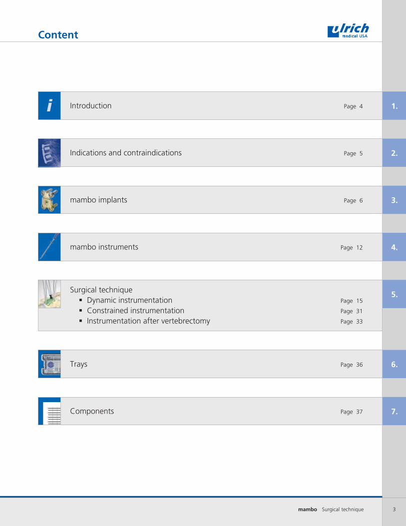
Surgical technique Dynamic instrumentation Page 15
Constrained instrumentation Page 31
Instrumentation after vertebrectomy Page 33
Introduction Page 4
Indications and contraindications Page 5
mambo implants Page 6
mambo instruments Page 12
Trays Page 36
Components Page 37
i
Content
4 mambo Surgical technique
1.
Art. Nr./Art. No. Art. Nr./Art. No.
Introduction
mambo is a cervical plate system for anterior stabilization of the spine. The implant immobilizes the fusion mass until the implant or the bone graft has fused.
The main feature of the system makes it possible to choose dynamic or rigid instru-mentation. Thanks to the modular design, the plates can be individually extended for multisegmental instrumentation. The integrated sliding mechanism offers the advantage of optimal positioning of the bone screws.
This description of the surgical technique contains the steps for using the mambo system. The implants and system instru-ments required for implantation are pre-sented.
The use of this manual is not sufficient as the sole basis for the successful application of the mambo system. It is recommended to learn the surgical technique from an experienced surgeon.
Please observe the instructions for sterilization and reprocessing of implants and instruments.
The small pictures at the bottom of the page show the step-by-step application of the instruments that are used as per the surgical steps on the double page. Pictures with instruments that had been used before are blue-colored.
5mambo Surgical technique
2.
mam
boIndications and contraindications
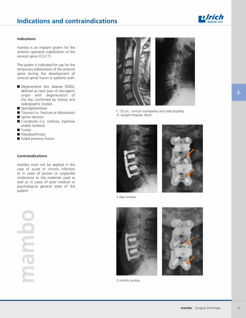
Indications
mambo is an implant system for the anterior operative stabilization of the cervical spine (C2-C7).
The system is indicated for use for the temporary stabilization of the anterior spine during the development of cervical spinal fusion in patients with:
■Degenerative disc disease (DDD), defined as neck pain of discogenic origin with degeneration of the disc confirmed by history and radiographic studies■Spondylolisthesis■Trauma (i.e. fracture or dislocation)■Spinal stenosis■Curvatures (i.e. scoliosis, kyphosis and/or lordosis)■Tumor■Pseudoarthrosis■Failed previous fusion
Contraindications
mambo must not be applied in the case of acute or chronic infection or in cases of proven or suspected intolerance to the materials used as well as in cases of poor medical or psychological general state of the patient.
3 days postop.
3 months postop.
f., 55 yrs., cervical myelopathy and radiculopathySt.-Joseph-Hospital, Berlin

6 mambo Surgical technique
3.
mambo implants
mambo plates
The mambo plate is available in five monosegmental lengths and in four bisegmental lengths.
Due to the mambo integrated sliding mecha-nism, the plate lengths are specified by the amount of translation or movement of the sliding mechanism(s). For example, a plate description of length S, 1-seg, 24 – 26 mm means that the plate length in the “compressed” state is 24 mm and in the fully distracted state is 26 mm.
The width of the plate is 18 mm for all lengths.
Length XXS Length XS Length S Length M Length L
1-seg (4-hole) 20 mm 22 - 24 mm 24 - 26 mm 26 - 30 mm 30 - 35 mm
2-seg (6-hole) -- 37 - 40 mm 40 - 45 mm 45 - 53 mm 53 - 62 mm
3-seg (8-hole) -- 52 - 56 mm 56 - 63 mm 63 - 75 mm 75 - 89 mm
4-seg (10-hole) -- 66 - 72 mm 72 - 82 mm 82 - 98 mm 98 - 115 mm
5-seg (12-hole) -- 81 - 88 mm 88 - 100 mm 100 - 120 mm 120 - 142 mm
Plate Length Amount of Translation
XS 1.5 mm
S 2.0 mm
M 4.0 mm
L 6.0 mm
18mm - width
8° pre-lordosed plateswith each level
2.5mm plate thickness
screw angulation +/- 10°avoid over angulation

7mambo Surgical technique
3.
mambo plates – preassembled
The mambo plate consists of several components.
Preassembled plates are in the tray for monosegmental and bisegmental instrumentation, each preassembled with settling screw(s) for dynamic instrumentation.
mambo implants
CS 1818-20 CS 1820-24
CS 1822-26 CS 1824-29
CS 1818-37 CS 1820-40
CS 1822-45 CS 1824-50

8 mambo Surgical technique
3.
mambo settling screw - dynamic plate construct
Settling and clamping screws connect the plate components together. The settling screw (CS 1826-01) is used for dynamic constructs.
Despite tightening the settling screw, the mobility of the plate components is not inhibited.
Wolff’s law of bone transformation says “every change in the function of a bone is followed by certain definite changes in internal architecture and external confor-mation in accordance with mathematical laws. This means that the external shape of a bone is well adapted to the forces placed upon them.“
mambo clamping screw -static plate construct
The clamping screw (CS 1826-02) is used for static construct.
By tightening the clamping screw, the mobility of the plate components is completely inhibited.
mambo implants
Settling screw
Clamping screw
StaticRigid
DynamicTranslational

9mambo Surgical technique
3.
mambo extension plates
Thanks to the modularity of the mambo system, extension plates can be used to lengthen the implant for multisegmental constructs.
The preassembled plate is extended with extension plate components depend-ing on the number of segments to be constructed.
The extension plates are available in the lengths XS, S, M and L.
Length XS Length S Length M Length L
mambo implants
10 mambo Surgical technique
3.
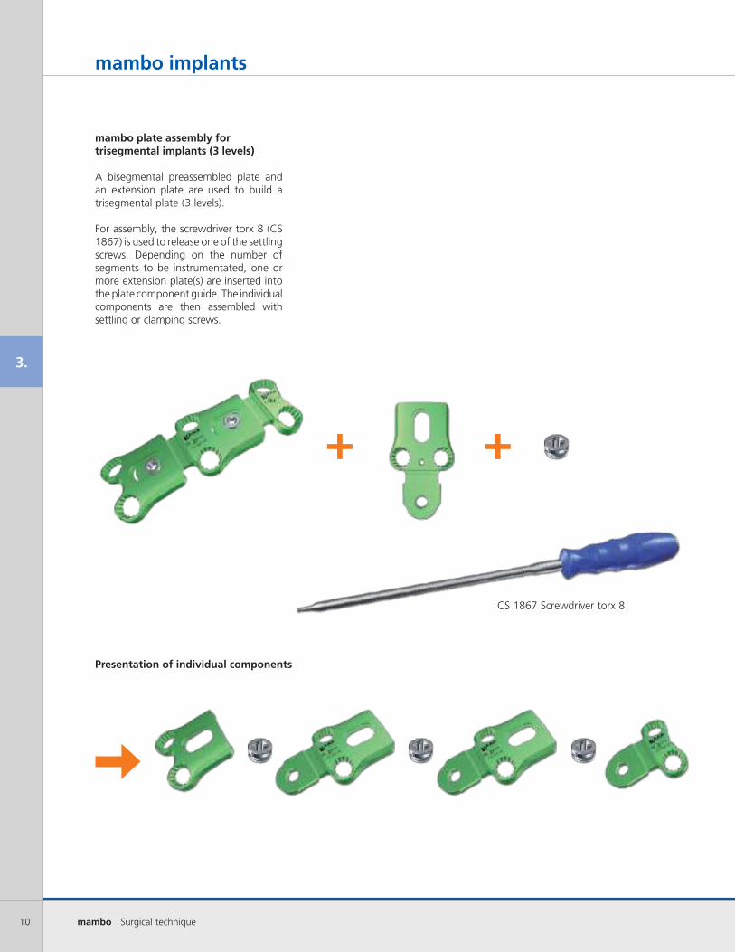
mambo plate assembly for trisegmental implants (3 levels)
A bisegmental preassembled plate and an extension plate are used to build a trisegmental plate (3 levels).
For assembly, the screwdriver torx 8 (CS 1867) is used to release one of the settling screws. Depending on the number of segments to be instrumentated, one or more extension plate(s) are inserted into the plate component guide. The individual components are then assembled with settling or clamping screws.
Presentation of individual components
mambo implants
CS 1867 Screwdriver torx 8
+ +
11mambo Surgical technique
3.
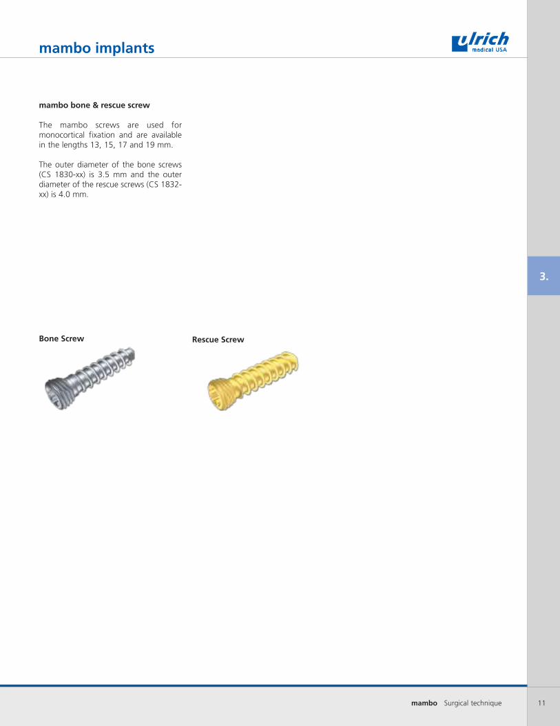
mambo bone & rescue screw
The mambo screws are used for monocortical fixation and are available in the lengths 13, 15, 17 and 19 mm.
The outer diameter of the bone screws (CS 1830-xx) is 3.5 mm and the outer diameter of the rescue screws (CS 1832-xx) is 4.0 mm.
Bone Screw Rescue Screw
mambo implants
12 mambo Surgical technique
4.
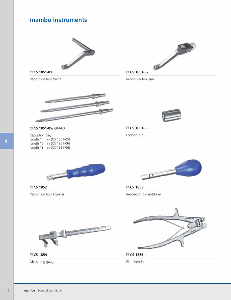
CS 1851-08
CS 1852
CS 1851-05/-06/-07
CS 1851-02
CS 1853
CS 1851-01
CS 1854 CS 1855
mambo instruments
Locking nut
Reposition tool adjuster
Reposition pin, length 14 mm (CS 1851-05) length 16 mm (CS 1851-06)length 18 mm (CS 1851-06)
Reposition tool arm
Reposition pin nutdriver
Reposition tool frame
Measuring gauge Plate bender

13mambo Surgical technique
4.
CS 1860
CS 1861
CS 1858
CS 1857
CS 1862
CS 1856
CS 1861-01 CS 1863
mambo instruments
Awl with sleeve
Double drill jig
Temporary fixation pin
Inserter for temporary fixation pin
Single drill jig
Plate holder
Depth adjuster Drill
14 mambo Surgical technique
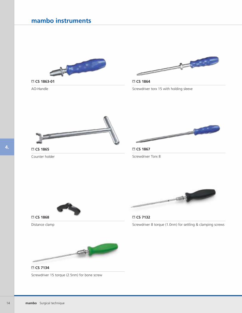
4. CS 1867
CS 1868 CS 7132
CS 7134
CS 1865
CS 1864 CS 1863-01
mambo instruments
Screwdriver Torx 8
Distance clamp Screwdriver 8 torque (1.0nm) for settling & clamping screws
Screwdriver 15 torque (2.5nm) for bone screw
Counter holder
Screwdriver torx 15 with holding sleeveAO-Handle
15mambo Surgical technique
5.
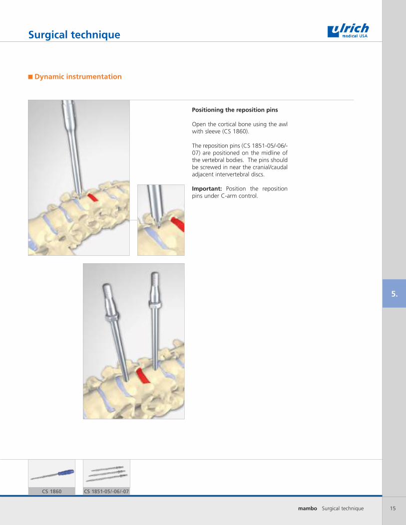
Positioning the reposition pins
Open the cortical bone using the awl with sleeve (CS 1860).
The reposition pins (CS 1851-05/-06/-07) are positioned on the midline of the vertebral bodies. The pins should be screwed in near the cranial/caudal adjacent intervertebral discs.
Important: Position the reposition pins under C-arm control.
Surgical technique
Dynamic instrumentation
CS 1860 CS 1851-05/-06/-07

16 mambo Surgical technique
5.
Positioning the reposition tool
The reposition tool arm (CS 1851-02) is pushed on the reposition tool frame (CS 1851-01) with the knob positioned vertically.
After placing the reposition pins, the reposition tool arms are placed on the pins and fixated with the locking nuts (CS 1851-08).
Surgical technique
CS 1852CS 1851-02CS 1851-01 CS 1851-08

17mambo Surgical technique
5.
Distraction/compression
The reposition tool adjuster (CS 1852) is placed on the reposition tool arm (CS 1851- 02).
The reposition tool adjuster (CS 1852) is used for distraction/compression.
Pull out and turn the knob on the reposition tool arm to set compression or distraction (according to the direction of the arrow).
After distraction, the intervertebral space can be removed and the bone graft or cage positioned. The optimal position of the plate on the vertebral body is achieved by removing the anterior soft tissue and removing prominent osteophytes.
Surgical technique
1
2
3

18 mambo Surgical technique
5.
CS 1854
Surgical technique
Determining the plate length
Preoperative planning of the optimal plate length is performed based on the current image data of the patient (x-rays or CT/MRI images).
The intraoperative determination of the optimal plate length is performed using the measuring gauge (CS 1854). After implantation of the bone graft or cage, the measuring gauge is introduced in situ and spread between the cranial and caudal reposition pins.
The measured length (mm) is read on the bottom edge of the measuring gauge.
Optional: After implantation of the bone graft or cage, the reposition tool can be removed.

19mambo Surgical technique
5.
Surgical technique
Selecting the implant
Based on the length measured, use layer for plates caddy (CS 1881-07), to select suitable plate.
The plate is determined by the number of segments to be instrumentated and by the measured distance.
For optimal settling, always select the smaller plate length.
Example: 1-segmental instrumentation, measuring length 30 M plate
20 mambo Surgical technique
5.lordosis
kyphosis
CS 1855
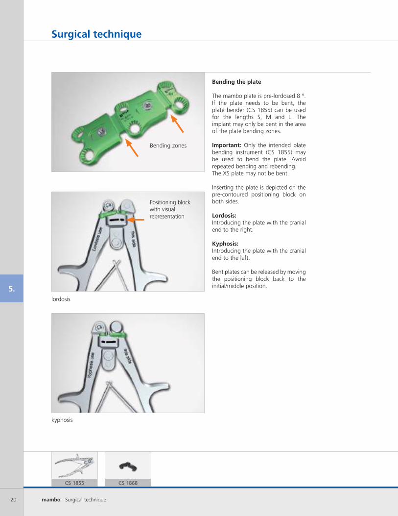
Positioning block with visual representation
Bending zones
CS 1868
Surgical technique
Bending the plate
The mambo plate is pre-lordosed 8 °. If the plate needs to be bent, the plate bender (CS 1855) can be used for the lengths S, M and L. The implant may only be bent in the area of the plate bending zones.
Important: Only the intended plate bending instrument (CS 1855) may be used to bend the plate. Avoid repeated bending and rebending.The XS plate may not be bent.
Inserting the plate is depicted on the pre-contoured positioning block on both sides.
Lordosis: Introducing the plate with the cranial end to the right.
Kyphosis: Introducing the plate with the cranial end to the left.
Bent plates can be released by moving the positioning block back to the initial/middle position.

21mambo Surgical technique
5.
Clamp hole
Surgical technique
Optional: Using distance clamp(s)
To maintain the minimum settling area of 1.5 mm when inserting the plate, the distance clamp (CS 1868) can be placed temporarily in the settling area of the plate.
The distance clamp is made of PEEK (polyetheretherketone), can be used for all plate lengths and is single-use.
Important: After screwing the plate to the vertebral bodies, remove the distance clamps.
As a reminder to remove the distance clamp(s), sutures can be attached to the clamp hole.
22 mambo Surgical technique
5.
CS 1856
pressed released
Surgical technique
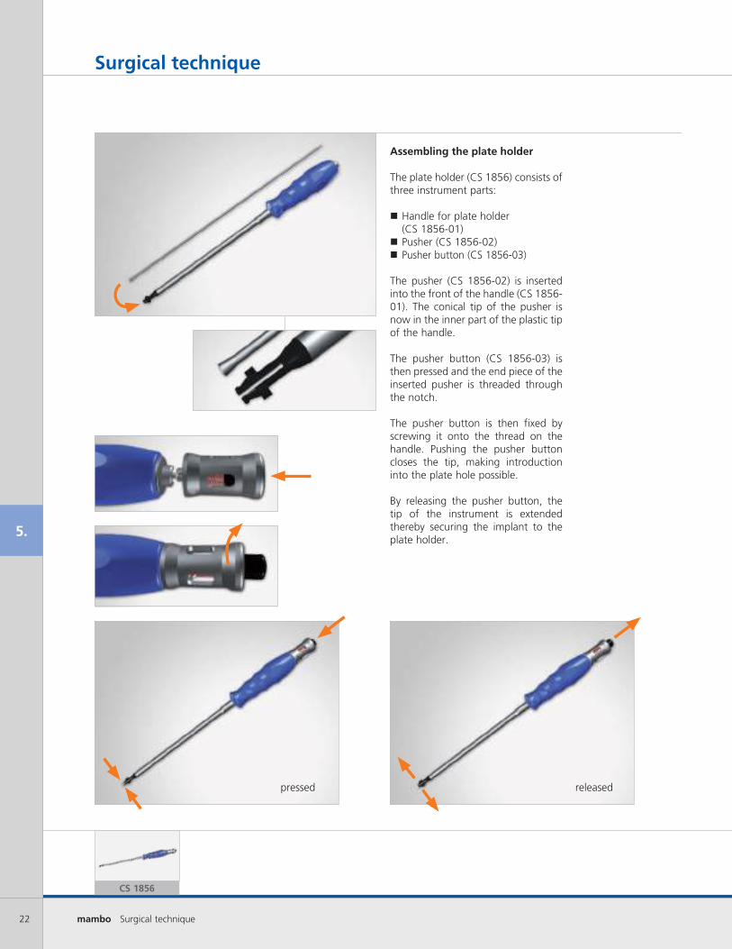
Assembling the plate holder
The plate holder (CS 1856) consists of three instrument parts:
� Handle for plate holder (CS 1856-01)
� Pusher (CS 1856-02) � Pusher button (CS 1856-03)
The pusher (CS 1856-02) is inserted into the front of the handle (CS 1856-01). The conical tip of the pusher is now in the inner part of the plastic tip of the handle.
The pusher button (CS 1856-03) is then pressed and the end piece of the inserted pusher is threaded through the notch.
The pusher button is then fixed by screwing it onto the thread on the handle. Pushing the pusher button closes the tip, making introduction into the plate hole possible.
By releasing the pusher button, the tip of the instrument is extended thereby securing the implant to the plate holder.
23mambo Surgical technique
5.
Surgical technique
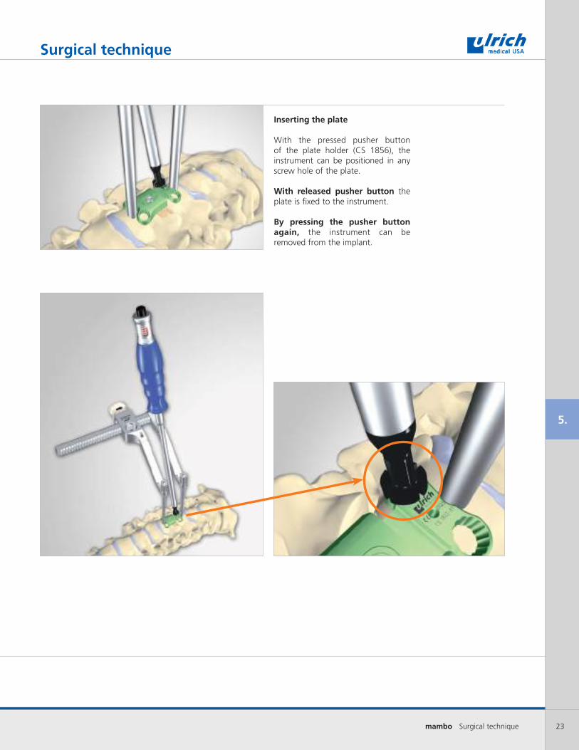
Inserting the plate
With the pressed pusher button of the plate holder (CS 1856), the instrument can be positioned in any screw hole of the plate.
With released pusher button the plate is fixed to the instrument.
By pressing the pusher button again, the instrument can be removed from the implant.
24 mambo Surgical technique
5.
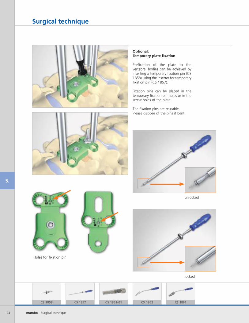
Optional:Temporary plate fixation
Prefixation of the plate to the vertebral bodies can be achieved by inserting a temporary fixation pin (CS 1858) using the inserter for temporary fixation pin (CS 1857).
Fixation pins can be placed in the temporary fixation pin holes or in the screw holes of the plate.
The fixation pins are reusable. Please dispose of the pins if bent.
CS 1858 CS 1857
Surgical technique
unlocked
Holes for fixation pin
locked
CS 1862 CS 1861CS 1861-01

25mambo Surgical technique
5.
Surgical technique
Assembling the drill jig
The depth adjuster (CS 1861-01) is inserted counterclockwise into the single (CS 1862) or double drill jig (CS 1861). The depth adjuster (CS1861-01) uses reverse threads so that the adjuster does not advance during drilling.
One revolution corresponds to 1.0 mm.
The depth/length for the drill or awl is determined based on the image data of the patient (x-rays or CT/MRI images). The drilling depth is adjusted using the depth adjuster (CS 1861-01).
The adjusted length can be viewed through the inspection window on the drill jig. The drill depth is displayed in 2 mm increments with numbers (11, 13, 15, 17, 19, 21) on the depth adjuster.
Use of the single or double drill jig depends on the approach and the surgeon‘s preference.
26 mambo Surgical technique
5.
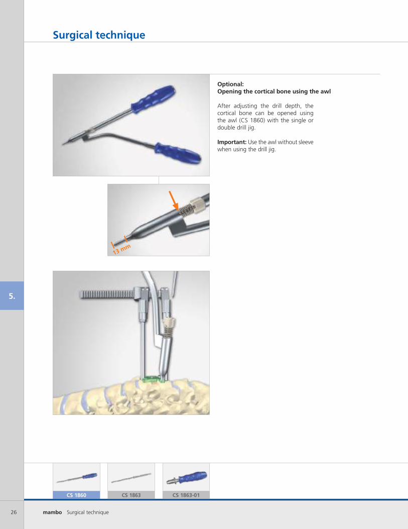
After adjusting the drill depth, the cortical bone can be opened using the awl (CS 1860) with the single or double drill jig.
Important: Use the awl without sleeve when using the drill jig.
Optional: Opening the cortical bone using the awl
Surgical technique
CS 1860 CS 1863 CS 1863-01
13 mm
27mambo Surgical technique
5.
Surgical technique
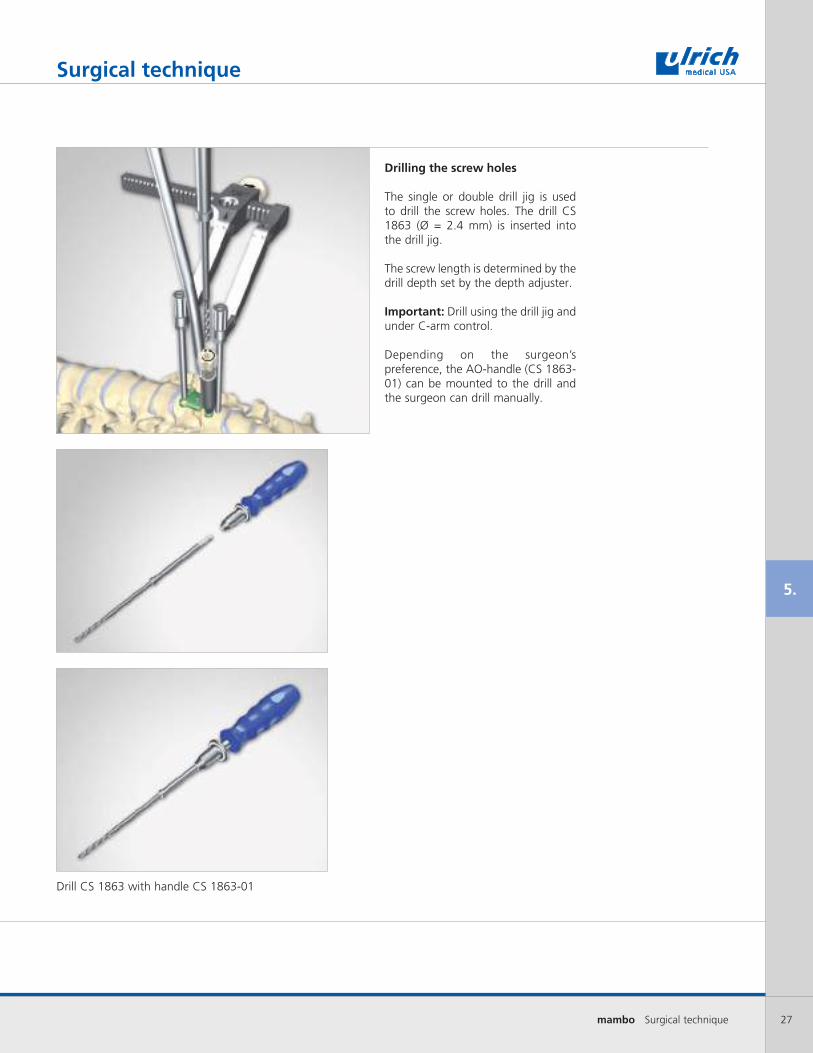
Drilling the screw holes
The single or double drill jig is used to drill the screw holes. The drill CS 1863 (Ø = 2.4 mm) is inserted into the drill jig.
The screw length is determined by the drill depth set by the depth adjuster.
Important: Drill using the drill jig and under C-arm control.
Depending on the surgeon’s preference, the AO-handle (CS 1863-01) can be mounted to the drill and the surgeon can drill manually.
Drill CS 1863 with handle CS 1863-01
28 mambo Surgical technique
5.
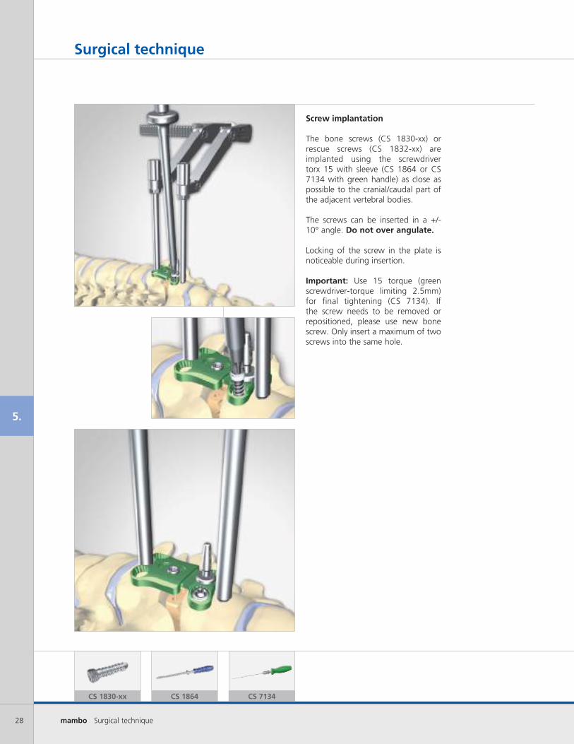
Screw implantation
The bone screws (CS 1830-xx) or rescue screws (CS 1832-xx) are implanted using the screwdriver torx 15 with sleeve (CS 1864 or CS 7134 with green handle) as close as possible to the cranial/caudal part of the adjacent vertebral bodies.
The screws can be inserted in a +/- 10° angle. Do not over angulate.
Locking of the screw in the plate is noticeable during insertion.
Important: Use 15 torque (green screwdriver-torque limiting 2.5mm) for final tightening (CS 7134). If the screw needs to be removed or repositioned, please use new bone screw. Only insert a maximum of two screws into the same hole.
Surgical technique
CS 1830-xx CS 1864 CS 7134

29mambo Surgical technique
5.
Surgical technique
Process as described in the previous steps (pages 27 - 28).
The reposition tool (knob positioned vertically on the reposition tool arm) can then be removed together with the reposition pins.
The screws can then be implanted on the opposing side in the same manner.
Preparing the second screw implantation
Settling
30 mambo Surgical technique
5.
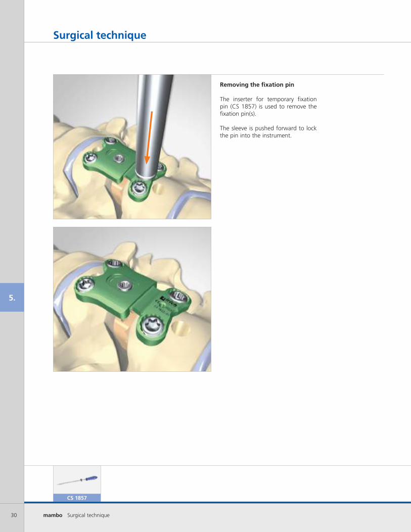
Removing the fixation pin
The inserter for temporary fixation pin (CS 1857) is used to remove the fixation pin(s).
The sleeve is pushed forward to lock the pin into the instrument.
Surgical technique
CS 1857
31mambo Surgical technique
5.
Surgical technique
Constrained or static plate constructs
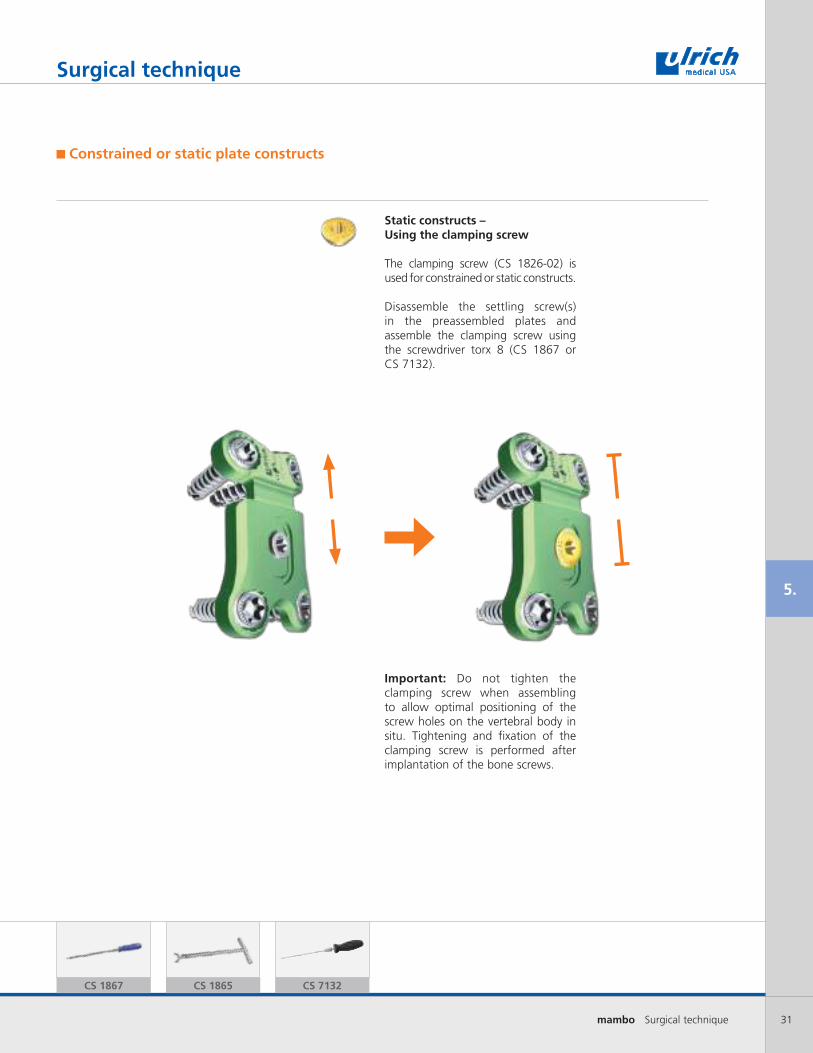
Static constructs – Using the clamping screw
The clamping screw (CS 1826-02) is used for constrained or static constructs.
Disassemble the settling screw(s) in the preassembled plates and assemble the clamping screw using the screwdriver torx 8 (CS 1867 or CS 7132).
Important: Do not tighten the clamping screw when assembling to allow optimal positioning of the screw holes on the vertebral body in situ. Tightening and fixation of the clamping screw is performed after implantation of the bone screws.
CS 1867 CS 1865 CS 7132
32 mambo Surgical technique
5.
Surgical technique
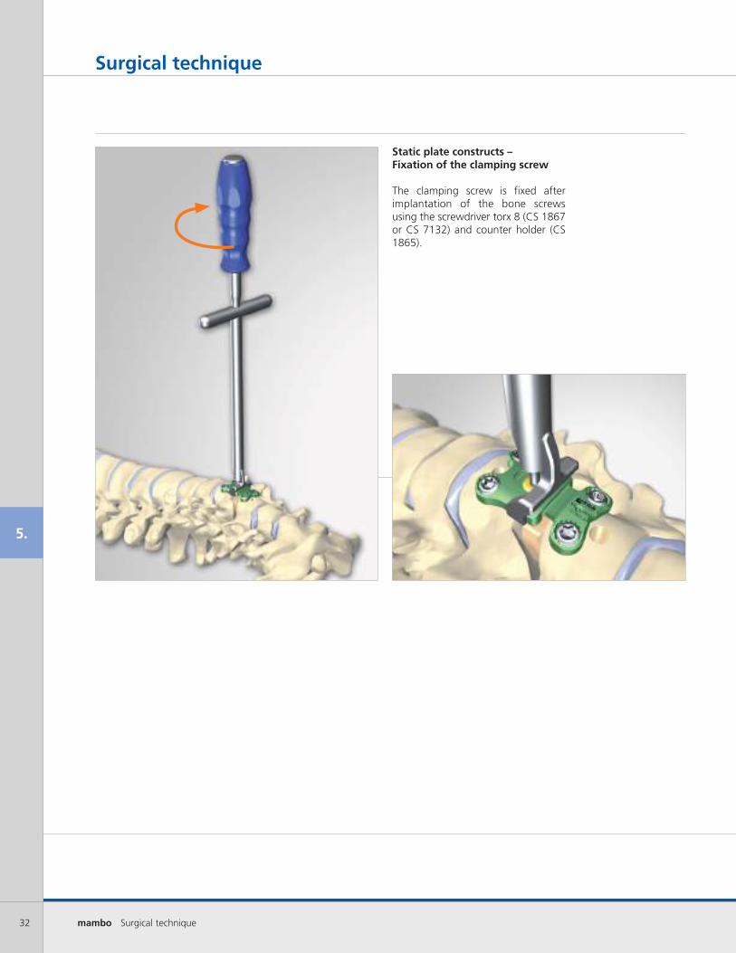
Static plate constructs – Fixation of the clamping screw
The clamping screw is fixed after implantation of the bone screws using the screwdriver torx 8 (CS 1867 or CS 7132) and counter holder (CS 1865).

33mambo Surgical technique
5.
Surgical technique
After vertebral body replacement
Important: When plating after vertebrectomy, it is recommended to block or use a clamping screw (CS 1826-02) in the level or segment of the vertebrectomy.
Instrumentation after vertebrectomy
Example: Presentation of individual components
Trisegmental instrumentation after vertebrectomy (blocking of two segments)

34 mambo Surgical technique
5.
3 days postop. 3 months postop.
Surgical technique
f., 81 yrs., cervical myelopathy, St.-Joseph-Hospital, Berlin

35mambo Surgical technique
5.
3 days postop. 3 months postop.
Surgical technique
f., 71 yrs., cervical myelopathy, St.-Joseph-Hospital, Berlin

36 mambo Surgical technique
6.
Trays
CS 1881-02
Top layer implants & measuring
CS 1881-03
Caddy for mambo screws
CS 1881-07
Caddy for mambo plates
CS 1881-05
Middle layer instrumentation
CS 1881-06
Bottom layer preparation & manipulation
37mambo Surgical technique
7.
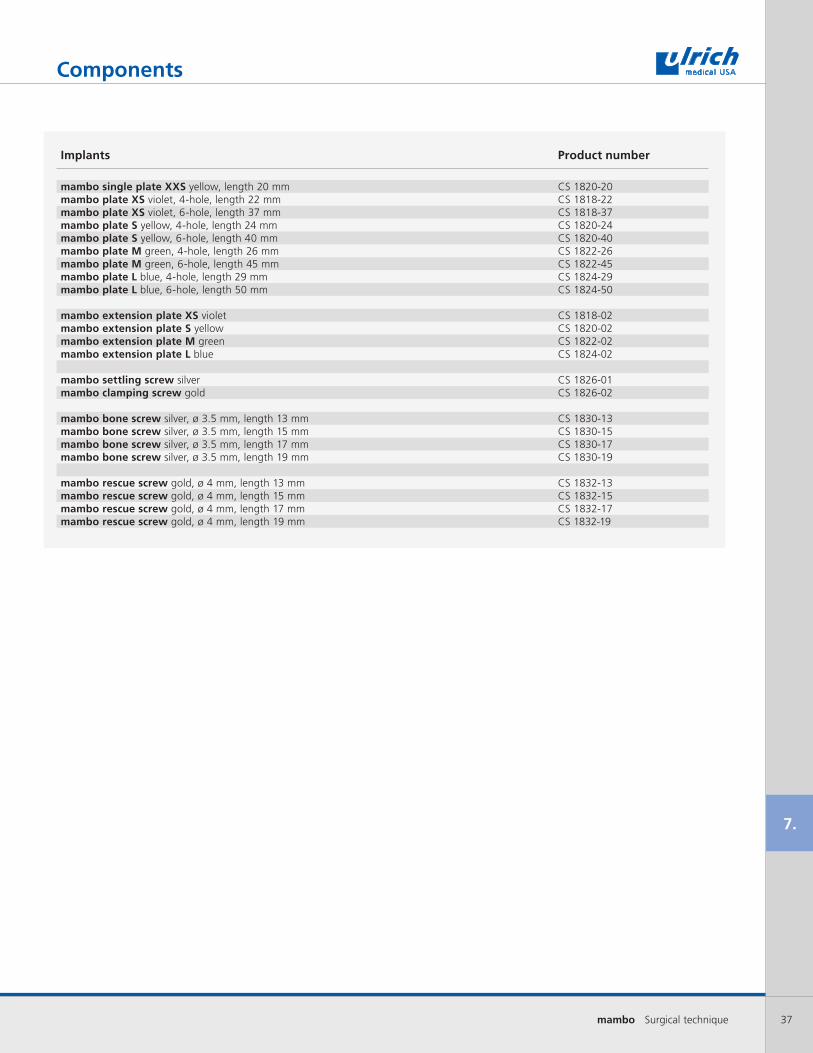
Components
Implants Product number
mambo single plate XXS yellow, length 20 mm CS 1820-20mambo plate XS violet, 4-hole, length 22 mm CS 1818-22mambo plate XS violet, 6-hole, length 37 mm CS 1818-37mambo plate S yellow, 4-hole, length 24 mm CS 1820-24mambo plate S yellow, 6-hole, length 40 mm CS 1820-40mambo plate M green, 4-hole, length 26 mm CS 1822-26mambo plate M green, 6-hole, length 45 mm CS 1822-45mambo plate L blue, 4-hole, length 29 mm CS 1824-29mambo plate L blue, 6-hole, length 50 mm CS 1824-50
mambo extension plate XS violet CS 1818-02mambo extension plate S yellow CS 1820-02mambo extension plate M green CS 1822-02mambo extension plate L blue CS 1824-02
mambo settling screw silver CS 1826-01mambo clamping screw gold CS 1826-02
mambo bone screw silver, ø 3.5 mm, length 13 mm CS 1830-13mambo bone screw silver, ø 3.5 mm, length 15 mm CS 1830-15mambo bone screw silver, ø 3.5 mm, length 17 mm CS 1830-17mambo bone screw silver, ø 3.5 mm, length 19 mm CS 1830-19
mambo rescue screw gold, ø 4 mm, length 13 mm CS 1832-13mambo rescue screw gold, ø 4 mm, length 15 mm CS 1832-15mambo rescue screw gold, ø 4 mm, length 17 mm CS 1832-17mambo rescue screw gold, ø 4 mm, length 19 mm CS 1832-19

38 mambo Surgical technique
7.
Components
Instruments Product number
Reposition tool CS 1851Reposition tool frame CS 1851-01Reposition tool arm CS 1851-02Reposition pin 14 mm CS 1851-05Reposition pin 16 mm CS 1851-06Reposition pin 18 mm CS 1851-07Locking nut CS 1851-08Reposition tool adjuster CS 1852Reposition pin nutdriver CS 1853Measuring gauge CS 1854Measuring lever CS 1854-01Handle for measuring lever CS 1854-02Plate bender CS 1855Plate holder CS 1856Handle for plate holder CS 1856-01Pusher CS 1856-02Pusher button CS 1856-03Inserter for temporary fixation pin CS 1857Handle for pin inserter CS 1857-01Holding sleeve for pin inserter CS 1857-02Temporary fixation pin CS 1858Temporary threaded fixation pin EO 2124Threaded fixation pin inserter EO 2123-1Awl with sleeve CS 1860Awl CS 1860-01Sleeve for awl CS 1860-02Double drill jig CS 1861Depth adjuster CS 1861-01Single drill jig CS 1862Drill CS 1863AO-Handle CS 1863-01Screwdriver torx 15 with holding sleeve CS 1864Screwdriver torx 15 CS 1864-01Holding sleeve for screwdriver torx 15 CS 1864-02Counter holder CS 1865Screwdriver torx 8 CS 1867Distance clamp CS 1868Screwdriver 8 torque limiting (1.0nm) CS 7132Screwdriver 15 torque limiting (2.5nm) CS 7134

39mambo Surgical technique
5.
4.
3.
1.
2.
7.
6.
39mambo Surgical technique
mam
bo
®
Surgical technique
ulrich GmbH & Co. KG l Buchbrunnenweg 12 l 89081 Ulm l GermanyTelefon/Phone: +49 (0)731 9654-0 l Fax national/international: +49 (0)731 9654-2705/[email protected] l www.ulrichmedical.com
WS
1801
R1/
2010
-09
Dru
ckfe
hler
und
Irrt
um v
orbe
halte
n l
With
res
erva
tions
of
mis
prin
ts a
nd e
rror
s
pat. pend.or/and
patented
mam
bo
™
US
1468
R1/
2014
-07
Over A Century Of Innovation
mam
bo
®mambo® modular cervical plate system
pat. pend.or/and
patented 18221 Edison Avenue, Chesterfield, MO 63005Phone: 866.519.0268 I Fax: 636.519.0271www.ulrichmedicalusa.com
World Headquartersulrich medical®
Buchbrunnenweg 1289081 Ulm, Germany