surgical technique guide - spineuniverse | expert advice on lower
TRANSCRIPT

SURGICAL TECHNIQUE GUIDE

FACET FIXATION SYSTEM SURGICAL TECHNIQUE GUIDE
2
Table of Contents
Pre-operative Steps . . . . . . . . . . . . . . . . . . . .3Assemble the FacetGun® MaxLoad a cassettePower
Patient Preparation & Exposure . . . . . . . . . . . .4
Decompression . . . . . . . . . . . . . . . . . . . . . . .4
Posterior IBF/Cage Insertion . . . . . . . . . . . . . .5
Preparation for FacetBolt® Placement . . . . . . . .5
Surgical Approach . . . . . . . . . . . . . . . . . . . .6
Pre-Awl/Pre-Drill . . . . . . . . . . . . . . . . . . . . . .7
Load the Fast Driver . . . . . . . . . . . . . . . . . . .7
Deploy the FacetBolt® . . . . . . . . . . . . . . . . . .8
Remove FacetGun® Max . . . . . . . . . . . . . . . .9
Confirm Implant Placement . . . . . . . . . . . . . . .9
Closure . . . . . . . . . . . . . . . . . . . . . . . . . . . .9
Implants & Instruments . . . . . . . . . . . . . . . . .10
Indications . . . . . . . . . . . . . . . . . . . . . . . . .10
Key Instruments . . . . . . . . . . . . . . . . . . . . . .11
Preface
With the advent of interbody fusion tech-niques, load sharing and stability has beenshifted away from the posterior spine, makinglarge pedicle screw/rod constructs less neededand the morbidity associated with the classicposterior open procedure less acceptable.Reducing morbidity and size of posteriorimplants is a worthwhile and now, achievablegoal; yet accomplishing this, while maintaininga rigid construct to promote fusion, stillremains all important.
The Amedica®/US Spine® Facet FixationSystem was developed to deliver, via minimalincision techniques, a small implant capableof rigid locking fixation over single or multiplelevels. The Locking FacetBolt®, placed acrossthe facet joint, secures a fixation point inclose proximity to the center of rotation,allowing the implant to be very small in sizeand yet deliver very strong stabilization.
The FacetGun® Max was developed todeliver the FacetBolt® using a minimal numberof steps, with a device that’s surgeon andteam friendly. It is ergonomically efficient,color coded and utilizes an “all-in-one” toolconcept, thus reducing hassles, trays andmultiple tools.
Facet fixation, which predates pedicle screwstabilization, has now come full circle in itsdevelopment and interest. With the advance-ment of interbody implants and approaches,the development of minimally invasive tech-niques and the addition of a locking mecha-nism, we believe you will find the LockingFacet Fixation System to be a very welcomeaddition to your stabilization techniques.
Mark H. Falahee, MD FACSMichigan Brain and Spine Institute

3
Surgical Technique
NOTES:A Power Drill and standard Jacob’s Chuck are required.This surgical technique is for a L4-L5 operative site.
Pre-operative Steps: (Performed by scrub team)
Assemble the FacetGun® MaxClose the hinged handle. Install both of the aluminum or plastic nuts securely.The larger nut fits on the back of the FacetGun®
Max handpiece.Use the Crimper to crimp the distal end of washertube 3-4 times, while simultaneously rotating instru-ment to ensure a secure fit with the proximal washer. Slide the outer tube over the barrel and tighten.
Load a cassette onto the FacetGun® MaxRemove cassette from packaging and ensure bothwashers are properly positioned. NOTE: Depending on patient anatomy, the proximalwasher can be flipped 180° to fit lamina. Rotate the barrel so it is in the unlocked position.Hold the cassette in the left hand and the FacetGun® Max hand-piece in the right hand. With the notches on the gun barrel in line with thearrows on the bridge, slide the bridge over the endof the hand-piece and rotate the hand-piece clock-wise. Tighten the barrel to secure the bridge.With the roll control lever in the vertical position,squeeze the hand-piece trigger to lock the proximalwasher into the end of the barrel. When secure, openthe door of the plastic cartridge and release the trigger(this will disengage the washer from the plastic). Remove the plastic cartridge from the assembled bridge and discard.
PowerConnect the Drill bit to a power drill with a Jacob’s chuck.Tighten the chuck with a key to ensure a confident grip.

FACET FIXATION SYSTEM SURGICAL TECHNIQUE GUIDE
4
Step 1: Patient Preparation & Exposure
Position the patient in prone position on a fluoroscopycompatible table. Take a lateral fluoroscopy view centered over L4/5 with an 18g spinal needle aimedat the L4/5 disc in a straight vertical position.
Prep/drape/ mark entry point of needle. Positionincision (4-8cm) in midline such that the needle markis at the halfway point of the overall incision.
Utilize a single cerebellar retractor to facilitate softtissue dissection down along the L4 spinous processand lamina to just beyond the L4/5 facet jointsbilaterally. Repeat fluoroscopy images as necessary.
Step 2: Decompression
Decompress the L4/5 interval preserving as much of the lamina as possible. Utilizing aSpinouspreader can facilitate this step, as described below.
Remove the L4/5 interspinous ligament. Distractbetween the L4 and L5 spinous processes with theSpinouspreader. Identify and remove the ligamentumflavum and a portion of the lamina/arthritis as necessary, exposing the exiting L5 nerve root (NR). Cauterize epidural vessels as necessary. Work opposite the Spinouspreader and then switchsides to complete a bilateral decompression.

5
Prepare Facet joint:
Have assistant use a handheld Meyerding retractorto retract the tissue just beyond the L4/5 facet jointto facilitate further exposure. Strip capsule, soft tissueand excess arthritic overgrowth from the facet joint. Remove soft tissue down to the transverse processof L5. Full exposure of the transverse process is notneeded. Optional: Remove facet cartilage and replace with an osteoconductive product. Use caution to not weaken bone architecture.Remove a portion of the caudal aspect of the L4spinous process to facilitate the FacetGun® trajectory.Preserve the more cephalad portion and the L3/4interspinous ligament.Use the Trial Gun to initially assess the trajectory and proper location for the FacetGun® Max andFacetBolt®.
NOTE: The goal is to place the FacetBolt® so it gripsfirmly across the facet joint. To achieve this, the distal-locking washer must be below the horizon of the facetjoint and the proximal washer must engage a fairly flatsurface of the lamina. Typically a small amount of bur-ring down of the “spine” of the lamina is needed to cre-ate a flat landing pad for the proximal washer. Feel theTrial Gun distal washer hit the transverse process andwalk it up from there and deep under the superior facetouter surface. Observe how the proximal washer mateswith the lamina surface and trim the surface flat as nec-essary. Once achieved, switch to the FacetGun® Max.
Step 3: Posterior Interbody Fusion Device/Cage Insertion (optional)
Place the Spinouspreader on the side opposite the one you wish to place a cage. Utilize a lateral fluoroscopy image to facilitate placement. Distract with Spinouspreader.Retract the L5 nerve root with a scoville retractor and expose the L4/5 disc space. Remove more lamina as necessary to achieve a straight trajectory into disc space.Utilize the Amedica/US Spine PLIF or TLIF instruments and interbody fusion devices. Reference the appropriate IFU and Surgical Technique for complete information.
NOTE: Cages may be placed obliquely if one implant is used or bilaterally if two implants areused. Switch sides and instruments and repeat steps to place the 2nd interbody fusion device.
Step 4: Preparation for FacetBolt® Placement
NOTE: You will be placing the FacetBolt® on the side opposite where you are standing. After placing one FacetBolt®, switch sides with your assistant and place the other FacetBolt®.

FACET FIXATION SYSTEM SURGICAL TECHNIQUE GUIDE
6
Surgical Approach
With the FacetGun® Max and a properly-loadedcassette, determine the proper trajectory over thedesired facet joint. NOTE: Be sure that you are able to visualize the lateral portion of the superior facet.
Aim the bridge towards the transverse process, feelthe distal-locking washer touch the transverse process,walk the distal-locking washer up and deep along the superior facet outer surface. Note: Do not dislodge the distal-locking washer.
Once the bridge is placed over the joint, pull backslightly to secure the distal-locking washer teeth ontothe outer surface of the superior facet. This will provide proper grip of the implant into the bone.
The roll controller at the top of the handpiece can be used to manipulate the washer-angle for properseating of the proximal washer on the laminar surface.
Position the proximal washer along the flat surface of the lamina, across the thickest portion of bone.
While holding the handpiece steady, compress thetrigger with one smooth controlled movement. Thiswill compress the joint and lock both of the washersonto the facet joint surfaces.NOTE: The FacetGun® Max, once engaged, is along lever arm. DO NOT MOVE or TORQUE. Werecommend positioning the forearm of your non-dominant hand on the patient and using the non-dominant hand to firmly, continuously grip the FacetGun® Max housing until the FacetBolt® is placed.
With the FacetGun® Max handpiece clamped intoposition on the facet joint, determine the properFacetBolt® length on the color-coded FacetBolt®
measurement grid located at the top of the hand-piece. The laser etched marking will align with thecolor and/or number that correspond to the appro-priate FacetBolt® length.NOTE: If the indicator is in-between sizes, selectthe shorter length.

7
Pre-Awl/Pre-Drill
Slide hand awl down the FacetGun® Max shaft and create a small indentation into the laminasurface for the drill.
(Prepared ahead of time) Connect the Drill bit to a power drill with a Jacob’s chuck.Tighten the chuck with a key to ensure a confident grip.
Insert the drill GENTLY into the back of the FacetGun® Max handpiece and drill forward andbackward slowly to create a channel for the FacetBolt®. Then remove the drill while main-taining speed with the drill motor.
Load the Fast Driver
Select the appropriate FacetBolt® length previously determined by the FacetBolt® measurement grid.NOTE: If the indicator is in-between sizes, select the shorter FacetBolt® length.
(Performed by scrub team while the surgeon prepsand drills) To load the FacetBolt®, grasp the FacetBolt® and with the hex assembly facing down,seat the hex end of the FacetBolt® flush into theFast Driver assembly shaft. When the FacetBolt®
is seated flush with the shaft, turn the retainer clockwise to engage the threaded portion of theretainer rod into the hex end of the FacetBolt®.Provisionally finger-tighten to avoid stripping the FacetBolt®. NOTE: Do not overtighten.
GENTLY slide the screw-end of the Fast Driverassembly into the open proximal end of the handpiece and apply moderate forward pressure.Rotation of the Fast Driver can help advance itthrough the facet joint to a fully-seated position. Thefully-seated position is indicated when the blackcolor band fills the window located posterior to the roll controller.NOTE: (optional) Connect the ratchet handle to theback of the Fast Driver. The direction selector onthe Ratchet Handle should be rotated to the left forclockwise advancement.

FACET FIXATION SYSTEM SURGICAL TECHNIQUE GUIDE
8
Deploy the FacetBolt®
When the Fast Driver is in the fully-seated position,turn the Fast Driver to advance the FacetBolt® intothe distal-locking washer. Gentle but firm pressure forward for the first one or two turns engages theFacetBolt® and the threaded shaft of the driver. From there, just turn clockwise with two or three fingers.NOTE: The driver shaft is threaded and will moveforward without pressure.
As the FacetBolt® is tightened, observe (surgeon/assistant) the “window” colors transitioning fromblack to gray to yellow. When the window iscompletely yellow, you will feel a positive stop. NOTE: Do not over-tighten.
Approximately two millimeters of the FacetBolt®
will be protruding through the distal-locking washer to ensure proper engagement of the locking mechanism.
Confirm with fluoroscopy prior to removal of the FacetGun® Max.

9
Remove the FacetGun® Max from the operative site
To remove the FacetGun® Max handpiece, first disen-gage the FacetBolt® from the Fast Driver by rotatingthe retainer counter-clockwise until it spins freely.
Release the clamp by depressing the clamp release. NOTE: If for some reason the proximal washer doesnot disengage from the washer tube, pull backslightly on the roll controller.
Place two fingers on the underside of the barrelwhere the barrel meets the housing while gentlyrolling the FacetGun® Max handpiece side-to-side,lift the gun in a plane towards your assistant. NOTE: Do not angle or lever the FacetGun® Max offthe distal-locking washer. Do not lift the FacetGun®
Max toward the ceiling.
Remove the FacetGun® Max from the wound site.Remove bridge and reload FacetGun® Max with a new cassette assembly.
Repeat steps to place a second FacetBolt® on the opposite side.
Once both FacetBolts® are in position, use the Distal Locking Retainer and the Bolt Tightener for final tightening. NOTE: Do not over-tighten. Tighten with two or threefinger tightness, feeling and listening for 2-4 clicks(max) as the proximal washer locks with the innerteeth of the FacetBolt® head.
Confirm Implant Placement
Confirm the implant position and fixation via fluoroscopy AP/LAT views.
Closure
If a TLIF or PLIF was preformed, it is recommendedto use a drain and to remove after day 1–2.
FACET FIXATION SYSTEM SURGICAL TECHNIQUE GUIDE
10
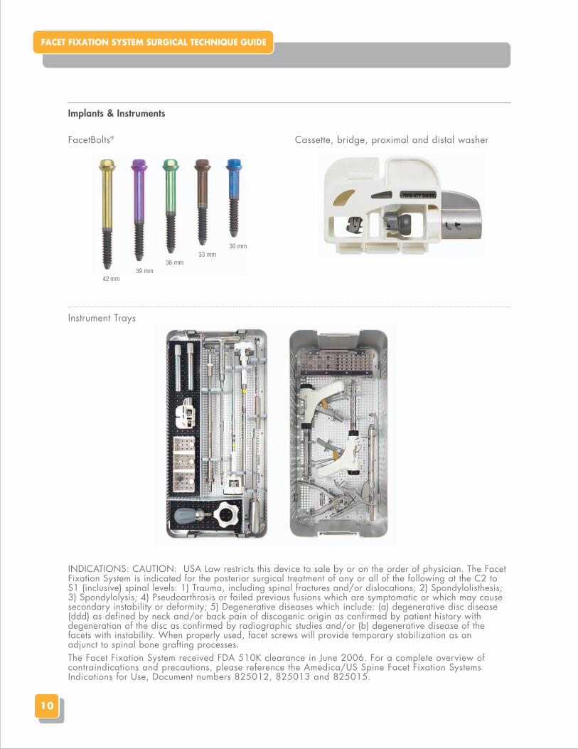
INDICATIONS: CAUTION: USA Law restricts this device to sale by or on the order of physician. The FacetFixation System is indicated for the posterior surgical treatment of any or all of the following at the C2 toS1 (inclusive) spinal levels: 1) Trauma, including spinal fractures and/or dislocations; 2) Spondylolisthesis;3) Spondylolysis; 4) Pseudoarthrosis or failed previous fusions which are symptomatic or which may causesecondary instability or deformity; 5) Degenerative diseases which include: (a) degenerative disc disease(ddd) as defined by neck and/or back pain of discogenic origin as confirmed by patient history withdegeneration of the disc as confirmed by radiographic studies and/or (b) degenerative disease of thefacets with instability. When properly used, facet screws will provide temporary stabilization as an adjunct to spinal bone grafting processes. The Facet Fixation System received FDA 510K clearance in June 2006. For a complete overview of contraindications and precautions, please reference the Amedica/US Spine Facet Fixation SystemsIndications for Use, Document numbers 825012, 825013 and 825015.
Implants & Instruments
FacetBolts® Cassette, bridge, proximal and distal washer
Instrument Trays
42 mm39 mm
36 mm33 mm
30 mm

11
Key Instruments
Trial Gun
Spinouspreader (Optional)
Fast Driver
Bolt Tightener Retainer – Distal Washer
Crimper
Ratchet Handle
Drill
FacetGun® Max Hand Piece

1885 West 2100 SouthSalt Lake City, UT 84119801.839.3500www.amedica.com
© 2011 Amedica Corporation. All rights reserved. 400025, Rev. A
Everything you need to succeed.
Silicon Nitride & PEEK IBF | Minimally Invasive Solutions | Cervical & Thoracolumbar Fixation | Facet Solutions | Deformity Correction | Biologics