surgical technique guide · and tissue dissection. ... assembly tool and compress the plate onto...
TRANSCRIPT
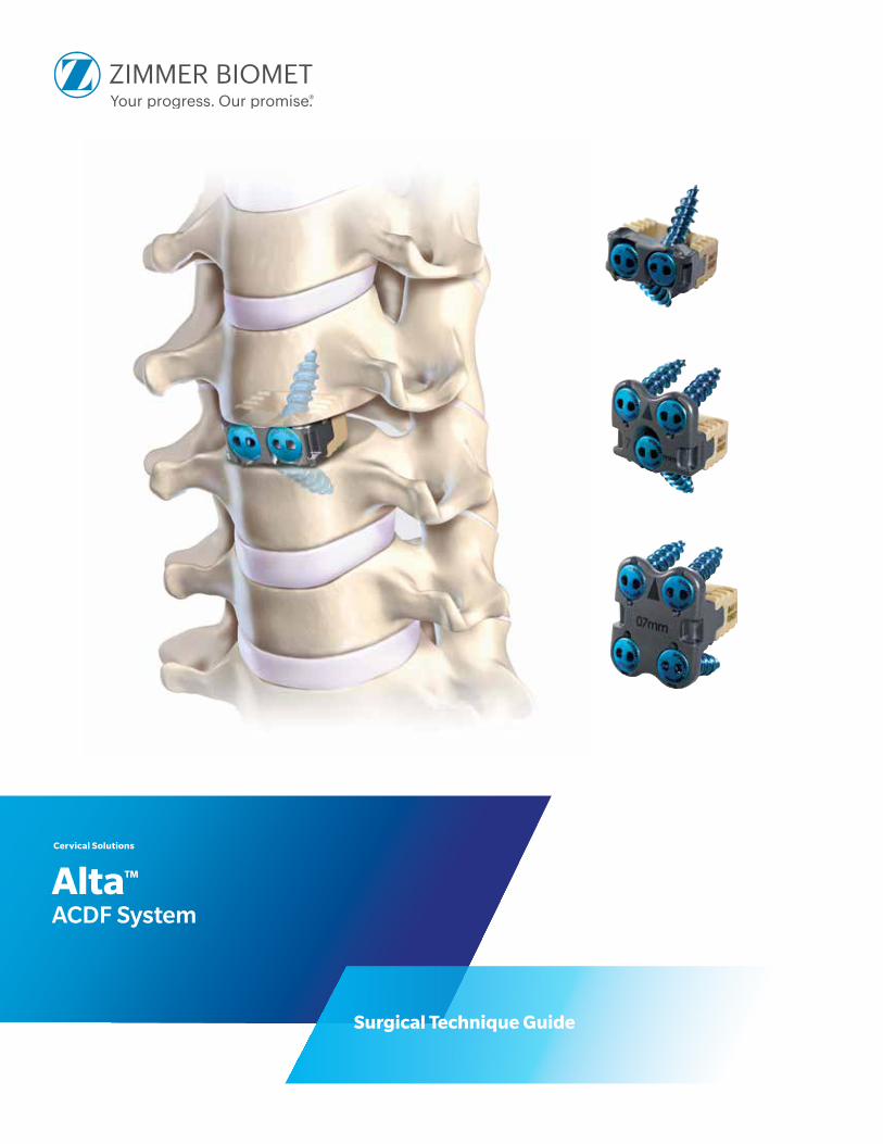
Alta™ ACDF System
Surgical Technique Guide
Cervical Solutions
2 Alta ACDF System—Surgical Technique Guide
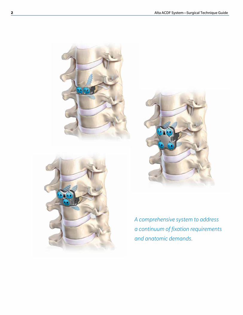
A comprehensive system to address
a continuum of fixation requirements
and anatomic demands.
Alta ACDF System—Surgical Technique Guide 3
System Overview 4
Preparation and Access 5
Implant Selection and Assembly 6
Implant Insertion 8
Freehand Screw Insertion 8
Drill Guide Screw Insertion 12
Securing the Locking Caps into the Alta Plate 15
Final Implant Position 17
Implant Removal 17
Screw Length and Angle Diagrams 18
Alta Instruments 20
Alta Graft Volumes 24
Important Information on the Alta ACDF System 26
TABLE OF CONTENTS
Zimmer Biomet Spine does not practice medicine. This technique was developed in
conjunction with health care professionals. This document is intended for surgeons and is not
intended for laypersons. Each surgeon should exercise his or her own independent judgment
in the diagnosis and treatment of an individual patient, and this information does not purport
to replace the comprehensive training surgeons have received. As with all surgical
procedures, the technique used in each case will depend on the surgeon’s medical judgment
as the best treatment for each patient. Results will vary based on health, weight, activity and
other variables. Not all patients are candidates for this product and/or procedure.
4 Alta ACDF System—Surgical Technique Guide
SYSTEM OVERVIEW
The Alta ACDF System is a cervical
interbody implant intended to
promote fusion in the cervical
region of the spine (C3–T1). By
combining the interbody and screws
into one implant system, the Alta
system performs the function of a
PEEK–OPTIMA® LT1 cervical
interbody spacer and an anterior
cervical plate.
The Alta system is distinguished among cervical systems by offering a variety of plate options to give the surgeon flexibility to accommodate varying anatomic and surgical requirements.
Each screw is prevented from backing out by a locking cap that provides an audible, tactile and visual confirmation that it is locked, resulting in a secure locking mechanism.
Other features of the Alta system include two footprint options with a full range of heights for a precise anatomical fit, very large graft windows for maximum fusion area and multiple technique options with intuitive instrumentation to seamlessly address a variety of clinical requirements.
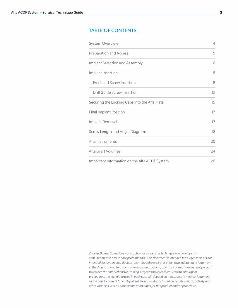
Full-Plate The Full-Plate construct offers four low-angle screws in the anterior cortex of the vertebral body. This option most closely approximates a standard anterior cervical plate system, while offering the convenience of a single construct for efficient implantation.
Zero-Plate The Zero-Plate construct sits entirely within the interbody space to minimize contact with the esophagus. The two screws that engage the vertebral endplates and the anti-rotation spikes provide adequate fixation while facilitating an efficient surgical procedure.
Half-Plate The Half-Plate construct, with two low-angle screws and one central endplate screw, offers additional options to deal with challenging anatomy. For example, the implant can be positioned in the upper cervical region with the low-angle screws positioned inferiorly, which allows for straight instruments to be used while avoiding the chin. The central screw is conveniently placed in the midline of the implant to avoid potential obstructions.

Alta ACDF System—Surgical Technique Guide 5
PREPARATION AND ACCESS
• Review and inspect all instrumentation and implants prior to sterilization.
• Replace or add any necessary components for the planned surgery.
• Surgeon must be fully experienced with the required spinal fusion techniques.
STEP 1
• Position and drape the patient in the usual fashion (Figure 1).
• Expose the affected levels via a standard incision and tissue dissection.
• Place any retraction pins in locations that will allow for the planned implant and instrumentation.
• Perform any necessary bone and tissue removal.
• Prepare vertebral endplates via the use of a combination of curettes, rasps, osteotomes, disc shavers or rongeurs to remove disc material and cartilage.
Mayo Stand
C-Arm Monitor
C-Arm
Figure 1 Patient positioning

6 Alta ACDF System—Surgical Technique Guide
IMPLANT SELECTION AND ASSEMBLY
STEP 2
The Alta Half-Plate and Full-Plate implants are designed to precisely fit the anatomy of the cervical spine. The Half-Plate is available in a Cranial version and a Caudal version. The Half-Plate and Full-Plate implants are marked by an arrow head “▲” indicating the cranial direction, which is duplicated on the corresponding trials.
Use the Half-Plate or Full-Plate trial to assess the fit of the plate against the anterior of the vertebral bodies and determine the degree of osteophyte removal necessary (Figure 3a, 3b, 3c).
Note: Half-Plate and Full-Plate trials are available in 15x13mm footprints only. Implants are available in 15x13mm and 17x14mm footprints.
• Insert the trials into the disc space to determine the size of the desired implant, starting with the smallest footprint and height of the trial, and progressing to larger and taller sizes as needed (Figure 2).
Figure 2 Trailing
Figure 3a
Figure 3cFigure 3b
Figure 3 Half-plate and full-plate trailing
Alta ACDF System—Surgical Technique Guide 7
STEP 3
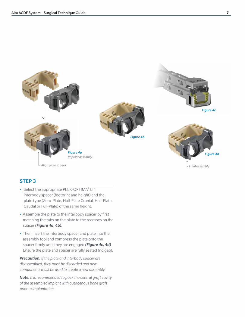
• Select the appropriate PEEK-OPTIMA® LT1 interbody spacer (footprint and height) and the plate type (Zero-Plate, Half-Plate Cranial, Half-Plate Caudal or Full-Plate) of the same height.
• Assemble the plate to the interbody spacer by first matching the tabs on the plate to the recesses on the spacer (Figure 4a, 4b).
• Then insert the interbody spacer and plate into the assembly tool and compress the plate onto the spacer firmly until they are engaged (Figure 4c, 4d). Ensure the plate and spacer are fully seated (no gap).
Precaution: If the plate and interbody spacer are disassembled, they must be discarded and new components must be used to create a new assembly.
Note: It is recommended to pack the central graft cavity of the assembled implant with autogenous bone graft prior to implantation.
Align plate to peek Final assembly
Figure 4a Implant assembly
Figure 4b
Figure 4c
Figure 4d

8 Alta ACDF System—Surgical Technique Guide
STEP 4A
• Select either the Zero-Plate freehand tip with stop, Zero-Plate freehand tip with no stop or Half-Plate and Full-Plate inserter tip, and assemble it to the inserter handle by pulling back on the sleeve, inserting the tip until fully seated, and releasing the outer sleeve.
• Turn the gold collar to the lock position to ensure the tip does not disengage from the inserter handle (Figure 5).
• Load the implant onto the inserter and secure by turning the black handle in a clockwise direction until tight. (Figure 6a, 6b).
IMPLANT INSERTION
For Zero-Plates, use Method A or Method B for inserting the implant and preparing and inserting the screws. For Half-Plates and Full-Plates, use only Method A.
Method A: Freehand Technique uses a tamp-style inserter to insert the implant and freehand instruments to prepare and insert the screws (pages 8–11).
Method B: Drill Guide Technique uses double-barreled fixed drill guides to insert the implant into the intervertebral disc space, and to prepare and insert the screws (pages 12–14).
METHOD A: FREEHAND SCREW INSERTION TECHNIQUE
STEP 5A
• Insert the assembled implant into the disc space (Figure 7). Radiographically confirm the position and placement of the implant.
Note: The edges of the radiographic markers are approximately 0.5mm from the posterior edge of the implant.
Note: For the Zero-Plate, the inserter may be left in place during screw insertion to maintain anterior placement of the implant.
Figure 5 Freehand inserter assembly
Figure 6a Loading implant
Figure 6b Figure 7 Freehand implant insertion

Alta ACDF System—Surgical Technique Guide 9
• Select the awl or drill, in straight or angled configuration, with a fixed or variable self-centering sleeve.
• Select the fixed angle sleeve (silver) to place the screw in the nominal trajectory or variable angle sleeve (gold) to aim the screw in an alternate trajectory (Figure 8). Fixed angle screws must be prepared using a fixed angle sleeve. Variable angle screws may be prepared using either fixed angle or variable angle sleeves, which allow for an additional 6° of angulation in any direction.
Note: The fixed or variable sleeve must be manually extended over the tip of the awl or drill prior to each insertion into the plate.
• The optional freehand awl does not have a self-centering sleeve. If the freehand awl is selected, care must be taken to insert it in the center of the screw hole at an appropriate orientation.
The angled driver is used to drive the angled awl or drill tips, as well as the angled screw driver tips. To assemble the angled driver, attach the AO handle to the shaft, then loosen the threaded cap (gold) until it slides freely. Retract the shaft slightly and insert a drill/awl or driver tip through the hole on the elbow of the sleeve. Reposition the shaft and assemble the threaded cap until fully seated (Figure 9a,9b,9c). Ensure the shaft and tip can rotate freely within the sleeve.
The optional side handle can be assembled to the angled driver by positioning it over the distal end of the sleeve, pulling back the trigger (gold) and sliding the side handle proximally until it stops. The orientation of the side handle can be adjusted by pulling back on the trigger and rotating the handle into position (Figure 10a,10b).
Figure 8 Freehand awl/drill selection
Figure 9a
Figure 9b
Figure 9c
Figure 10 Angled driver assembly
Figure 10b
STEP 6A

10 Alta ACDF System—Surgical Technique Guide
Method A: Freehand Screw Insertion Technique (continued)
• Insert the tip of the awl or drill into the screw pocket on the plate and then insert the awl or drill into the bone until the stop is reached (Figure 11).
• The inserter handle must be removed prior to preparing the screws for the Half-Plate or Full-Plate (Figure 12a,12b).
• For the Half-Plate, start by preparing and fully inserting the center screw of the Half-Plate in order to lag the implant against the anterior cortex prior to inserting the screws on the flange.
Figure 11 Freehand awl/dril insertion
Figure 12b Full-plate screw preparation
Figure 12a Half-plate screw preparation
STEP 7A

Alta ACDF System—Surgical Technique Guide 11
STEP 8A
• Load the appropriate length and type of screw (see page 23) onto the straight screw driver or angled screw driver. A diagram of the screw lengths is provided on page 18.
Note: Short driver tip should only be used if inserter has been removed prior to screw insertion.
• Insert the screw into the prepared screw hole (Figure 13).
Note: Fixed angle screws can only be used when the bone is prepared using fixed angle self-centering sleeves.
STEP 9A
• Remove the inserter by turning the black handle in a counterclockwise direction until the implant is fully released (Figure 14).
Continue to Step 10 on page 15.
Figure 13 Freehand screw insertion
Figure 14 Freehand inserter removal

12 Alta ACDF System—Surgical Technique Guide
• Assemble the appropriate height drill guide tip to the inserter handle by pulling back on the sleeve, inserting the drill guide until fully seated and releasing the outer sleeve (Figure 15a).
• Turn the gold collar to the lock position to ensure the tip does not disengage from the inserter handle (Figure 15b).
• Load the implant onto the inserter and secure by turning the black handle in a clockwise direction until tight (Figure 16).
METHOD B: DRILL GUIDE SCREW INSERTION TECHNIQUE
Continued from page 7 after Step 3.
STEP 4B
Figure 15a
Figure 15b
Figure 16 Inserter attachment
Figure 15 Drill guide assembly

Alta ACDF System—Surgical Technique Guide 13
STEP 5B
• Insert the assembled implant into the disc space (Figure 17). Radiographically confirm the position and placement of the implant.
Note: The edges of the radiographic markers are approximately 0.5mm from the posterior edge of the implant (see page 22).
STEP 6B
• Select the awl or drill, in straight or angled configuration, with the fixed angle sleeve (see page 9 for angled driver assembly).
Note: The fixed sleeve must be manually extended over the tip of the awl or drill prior to each insertion into the guide.
• Sequentially insert the awl or drill into both barrels of the drill guide until the stop is reached (Figure 18).
Figure 17 Drill guide implant insertion
Figure 18 Drill guide awl/drill insertion
14 Alta ACDF System—Surgical Technique Guide
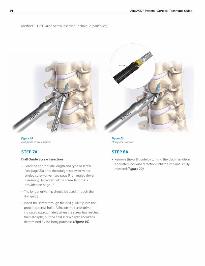
STEP 7A
Drill Guide Screw Insertion
• Load the appropriate length and type of screw (see page 23) onto the straight screw driver or angled screw driver (see page 9 for angled driver assembly). A diagram of the screw lengths is provided on page 18.
• The longer driver tip should be used through the drill guide.
• Insert the screw through the drill guide tip into the prepared screw hole. A line on the screw driver indicates approximately when the screw has reached the full depth, but the final screw depth should be determined by the bony purchase (Figure 19).
STEP 8A
• Remove the drill guide by turning the black handle in a counterclockwise direction until the implant is fully released (Figure 20).
Method B: Drill Guide Screw Insertion Technique (continued)
Figure 19 Drill guide screw insertion
Figure 20 Drill guide removal

Alta ACDF System—Surgical Technique Guide 15
STEP 9
• Assemble the locking cap inserter by sliding the outer sleeve over the inner shaft.
• To load a locking cap, slide the sleeve of the locking cap inserter towards the handle to the unlock position, then insert the tips of the locking cap inserter through the holes of the locking cap, and finally slide the locking cap inserter sleeve downwards until resistance is felt. The tip of the sleeve will not touch the locking cap (Figure 21).
Note: High angle locking caps are available in the caddy if the standard locking cap does not fit over the screw head.
STEP 10
• Insert the locking cap into the plate with the locking cap tabs and the line on the inserter oriented in the direction of the cut-outs on the plate (Figure 22a).
• Rotate the locking cap clockwise until the line on the inserter is approximately 60° from cranial-caudal. A tactile “click” should be felt as the cap locks into position (Figure 22b). Do not turn beyond this “click.”
Removing the Locking Cap Inserter
• Slide the sleeve of the locking cap inserter upward towards the handle to disengage the locking cap inserter from the locking cap.
SECURING THE LOCKING CAPS INTO THE ALTA PLATE
For all plate configurations, a locking cap is used over each screw head to prevent the screw from backing out.
Caution: Locking caps are single-use and must not be reused after locking into the plate assembly.
Figure 21 Locking cap inserter assembly
Figure 22a Inserting the locking cap
Figure 22b

16 Alta ACDF System—Surgical Technique Guide
Securing the Locking Caps into the Alta Plate (continued)
STEP 11
• Visually confirm that the locking caps are in their final secured position by verifying the two holes in the locking caps are horizontal to the body axis. Additionally, confirm that the locking cap tabs are NOT visible. The caps are free to wiggle slightly. (Figure 23).
Figure 23 Inspect the locking cap

Alta ACDF System—Surgical Technique Guide 17
STEP 12
• Inspect final implant for correct position and assembly. (Zero-Plate: Figure 24; Half-Plate Caudal: Figure 25; Half-Plate Cranial: Figure 26; Full-Plate: Figure 27).
• Close the fascia and skin incision in the usual manner.
FINAL IMPLANT POSITION
Zero-Plate Half-Plate Caudal
Half-Plate Cranial Full-Plate
REMOVING THE ALTA IMPLANT (if necessary)
• Remove the locking caps with the locking cap inserter by inserting the tip into the caps, sliding the sleeve down and turning the caps 60° counterclockwise.
• Remove all screws using the straight screw driver or angled screw driver.
• Attach the inserter tip to the inserter handle, and tighten to the plate by turning the black handle in a clockwise direction (Refer to page 8, Figures 6a and 6b).
• Pull the inserter until the implant is removed from the disc space.
Figure 27
Figure 25
Figure 26
Figure 24

18 Alta ACDF System—Surgical Technique Guide
ALTA SCREWS LENGTH DIAGRAMS
6.5 1.56.5
0.55.30.0
6.4
5.7
0.0
0.7
6.4
6.8
0.9
2.0
6.4
6.8
1.0
0.0
5.9
6.5
2.0
1.5 6.9
6.7
1.0
0.96.9
6.7
0.0
0.0
5.6
5.8
2.1
0.25.8
5.9
1.1
0.85.8
5.9
1.8
0.0
Zero-Plate
Half-Plate Cranial
Half-Plate Caudal
Full-Plate
Small Spacer (15x13mm) 12mm Screw
Small Spacer (15x13mm) 14mm Screw
Large Spacer (17x14mm) 14mm Screw
Small Spacer (15x13mm) 12mm Screw
Small Spacer (15x13mm) 14mm Screw
Large Spacer (17x14mm) 14mm Screw
Small Spacer (15x13mm) 12mm Screw
Small Spacer (15x13mm) 14mm Screw
Large Spacer (17x14mm) 14mm Screw
Small Spacer (15x13mm) 12mm Screw
Small Spacer (15x13mm) 14mm Screw
Large Spacer (17x14mm) 14mm Screw

Alta ACDF System—Surgical Technique Guide 19
Zero-Plate Half-Plate Cranial
Half-Plate Caudal Full-Plate
12°
35°
35°
10°
35°
10°
10°
35°
10°
10°
10°
10°
ALTA SCREWS ANGLE DIAGRAMS
20 Alta ACDF System—Surgical Technique Guide
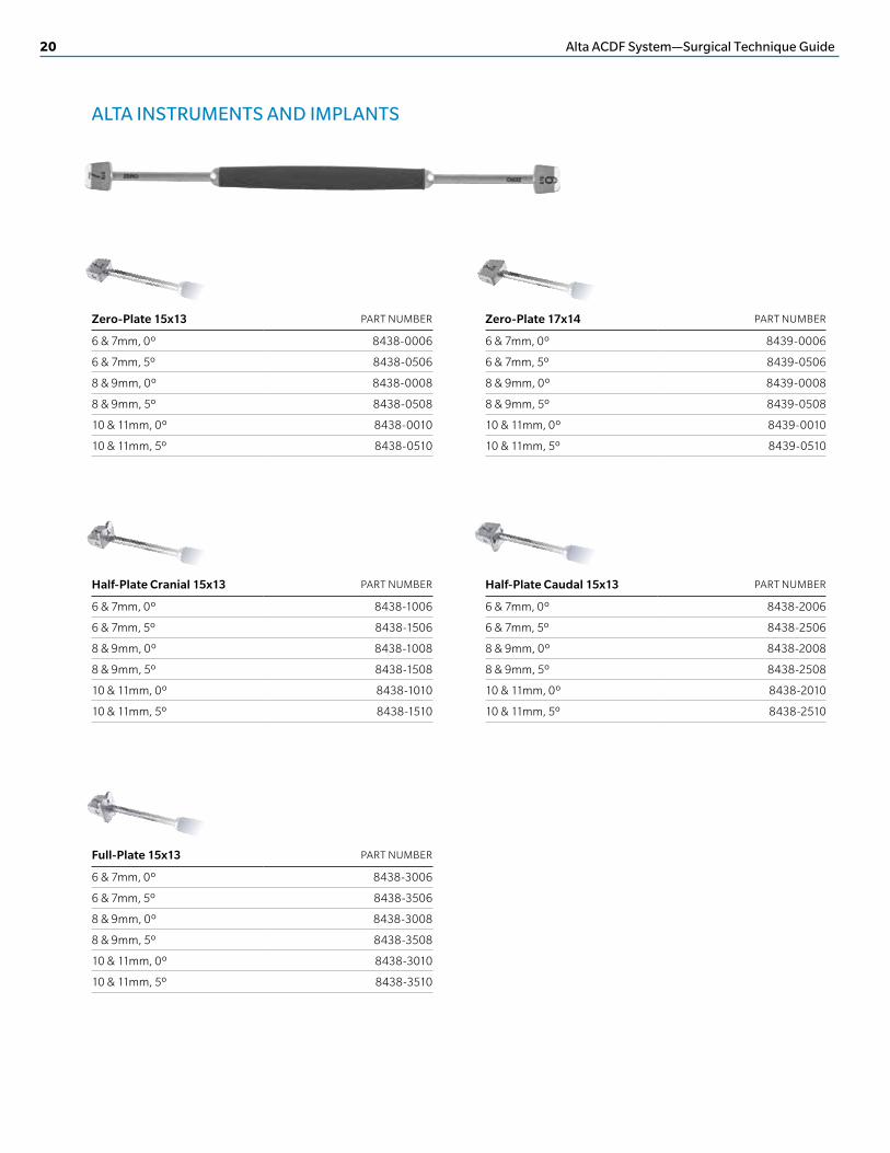
ALTA INSTRUMENTS AND IMPLANTS
Zero-Plate 15x13 PART NUMBER
6 & 7mm, 0º 8438-0006
6 & 7mm, 5º 8438-0506
8 & 9mm, 0º 8438-0008
8 & 9mm, 5º 8438-0508
10 & 11mm, 0º 8438-0010
10 & 11mm, 5º 8438-0510
Zero-Plate 17x14 PART NUMBER
6 & 7mm, 0º 8439-0006
6 & 7mm, 5º 8439-0506
8 & 9mm, 0º 8439-0008
8 & 9mm, 5º 8439-0508
10 & 11mm, 0º 8439-0010
10 & 11mm, 5º 8439-0510
Half-Plate Cranial 15x13 PART NUMBER
6 & 7mm, 0º 8438-1006
6 & 7mm, 5º 8438-1506
8 & 9mm, 0º 8438-1008
8 & 9mm, 5º 8438-1508
10 & 11mm, 0º 8438-1010
10 & 11mm, 5º 8438-1510
Half-Plate Caudal 15x13 PART NUMBER
6 & 7mm, 0º 8438-2006
6 & 7mm, 5º 8438-2506
8 & 9mm, 0º 8438-2008
8 & 9mm, 5º 8438-2508
10 & 11mm, 0º 8438-2010
10 & 11mm, 5º 8438-2510
Full-Plate 15x13 PART NUMBER
6 & 7mm, 0º 8438-3006
6 & 7mm, 5º 8438-3506
8 & 9mm, 0º 8438-3008
8 & 9mm, 5º 8438-3508
10 & 11mm, 0º 8438-3010
10 & 11mm, 5º 8438-3510

Alta ACDF System—Surgical Technique Guide 21
Assembly Tool PART NUMBER
8434-1000
Zero-Plate Guide Tip PART NUMBER
6mm 8434-1406
7mm 8434-1407
8mm 8434-1408
9mm 8434-1409
10mm 8434-1410
11mm 8434-1411
Inserter Handle PART NUMBER
8431-1400
Tamp PART NUMBER
8435-0002
Locking Cap Inserter PART NUMBER
8431-1100
Zero-Plate Freehand Tip with Stop PART NUMBER
8431-1403
Zero-Plate Freehand Tip No Stop PART NUMBER
8431-1401
Half-Plate and Full Plate Inserter Tip PART NUMBER
8431-1404

22 Alta ACDF System—Surgical Technique Guide
Straight Awl Variable Tip PART NUMBER
12mm 8430-1102
ALTA INSTRUMENTS AND IMPLANTS (continued)
Straight Awl Fixed Tip PART NUMBER
12mm 8430-1202
Freehand Awl PART NUMBER
12mm 8430-1402
Straight Screw Driver PART NUMBER
8430-1101
Straight Drill - Variable PART NUMBER
10mm 8430-1110
12mm 8430-1112
14mm 8430-1114
16mm 8430-1116
18mm 8430-1118
Angled Driver PART NUMBER
8430-1000
Angled Driver Side Handle PART NUMBER
8430-1006
Angled Awl Tips 12mm PART NUMBER
Variable 8430-1002
Fixed 8430-1003
Angled Screw Driver Tips PART NUMBER
Long 8430-1004
Short 8430-1005
Straight Drill - Fixed PART NUMBER
10mm 8430-1210
12mm 8430-1212
14mm 8430-1214
16mm 8430-1216
18mm 8430-1218
Angled Drill Tips - Variable PART NUMBER
10mm 8430-0110
12mm 8430-0112
14mm 8430-0114
16mm 8430-0116
18mm 8430-0118
Angled Drill Tips- Fixed PART NUMBER
10mm 8430-0210
12mm 8430-0212
14mm 8430-0214
16mm 8430-0216
18mm 8430-0218

Alta ACDF System—Surgical Technique Guide 23
Straight Tap PART NUMBER
12mm 8435-1235
AO Handle PART NUMBER
12mm 9801-0173
Angled Tap Tip PART NUMBER
12mm 8434-1235
PEEK Spacers Small 15x13 Large 17x14
6mm, 0º 8411-0006 8412-0006
7mm, 0º 8411-0007 8412-0007
8mm, 0º 8411-0008 8412-0008
9mm, 0º 8411-0009 8412-0009
10mm, 0º 8411-0010 8412-0010
11mm, 0º 8411-0011 8412-0011
6mm, 5º 8411-0506 8412-0506
7mm, 5º 8411-0507 8412-0507
8mm, 5º 8411-0508 8412-0508
9mm, 5º 8411-0509 8412-0509
10mm, 5º 8411-0510 8412-0510
11mm, 5º 8411-0511 8412-0511
15
13
17
14
Plates Zero-Plate Half-Plate Cranial
Half-Plate Caudal Full-Plate
6mm 8409-0006 8409-1106 8409-2106 8409-1206
7mm 8409-0007 8409-1107 8409-2107 8409-1207
8mm 8409-0008 8409-1108 8409-2108 8409-1208
9mm 8409-0009 8409-1109 8409-2109 8409-1209
10mm 8409-0010 8409-1110 8409-2110 8409-1210
11mm 8409-0011 8409-1111 8409-2111 8409-1211
Self-Tapping Screws - Fixed Standard (3.5mm) Rescue (4.0mm)
12mm 8424-3512 8424-4012
14mm 8424-3514 8424-4014
16mm 8424-3516 8424-4016
18mm 8424-3518 8424-4018
Self-Tapping Screws - Variable Standard (3.5mm) Rescue (4.0mm)
12mm 8426-3512 8426-4012
14mm 8426-3514 8426-4014
16mm 8426-3516 8426-4016
18mm 8426-3518 8426-4018
Self-Drilling Screws - Fixed
Standard (3.5mm)
Rescue (4.0mm)
12mm 8425-3512 8425-4012
14mm 8425-3514 8425-4014
16mm 8425-3516 8425-4016
18mm 8425-3518 8425-4018
Self-Drilling Screws - Variable
Standard (3.5mm)
Rescue (4.0mm)
12mm 8427-3512 8427-4012
14mm 8427-3514 8427-4014
16mm 8427-3516 8427-4016
18mm 8427-3518 8427-4018
Locking Caps PART NUMBER
Standard 8405-1000
High Angle 8405-1203

24 Alta ACDF System—Surgical Technique Guide
Plates Zero-Plate Half-Plate Cranial
Half-Plate Caudal Full-Plate
6mm 0.34cc 0.38cc 0.42cc 0.47cc
7mm 0.40cc 0.45cc 0.49cc 0.55cc
8mm 0.46cc 0.51cc 0.56cc 0.62cc
9mm 0.52cc 0.58cc 0.63cc 0.70cc
10mm 0.58cc 0.64cc 0.70cc 0.78cc
11mm 0.64cc 0.71cc 0.77cc 0.86cc
GRAFT VOLUMES
Graft Volume - Small (15x13mm), 5º Lordosis*
Plates Zero-Plate Half-Plate Cranial
Half-Plate Caudal Full-Plate
6mm 0.42cc 0.46cc 0.49cc 0.54cc
7mm 0.49cc 0.54cc 0.58cc 0.63cc
8mm 0.56cc 0.62cc 0.66cc 0.73cc
9mm 0.64cc 0.70cc 0.74cc 0.82cc
10mm 0.71cc 0.77cc 0.83cc 0.91cc
11mm 0.64cc 0.85cc 0.91cc 1.01cc
Graft Volume - Large (17x14mm), 5º Lordosis*
* For 0º Parallel, add 0.02cc.
ALTA MARKER PLACEMENT
3.7 0.5
Tantalum Pin Ø 1.0

Alta ACDF System—Surgical Technique Guide 25

26 Alta ACDF System—Surgical Technique Guide
Device DescriptionThe Alta System device is a cervical interbody fusion device consisting of a PEEK-OPTIMA LT1® intervertebral spacer, titanium plate and screws. The PEEK spacer has a generally rounded shape with various heights and footprints and has a central cavity to accommodate autogenous bone graft. The upper and lower surfaces have a series of transverse grooves formed to improve stability and fixation once the device is inserted. The titanium plate has holes for receiving bone screws and features to assemble locking caps to prevent screw back-out. The Alta system is available in a variety of sizes and configurations to approximate anatomical variation in different vertebral levels and/or patient anatomy. The Alta system is provided non-sterile.
Indications For UseThe Alta system is a stand-alone cervical fusion device intended for use in skeletally mature patients with degenerative disc disease (DDD) of the cervical spine (C3–T1) at one level. DDD is defined as discogenic pain with degeneration of the disc confirmed by history and radiographic studies. These patients should be skeletally mature and have had at least six (6) weeks of non-operative treatment. The Alta device is to be filled with autogenous bone graft material, and is to be used with titanium alloy screws which accompany the implant.
ContraindicationsContraindications may be relative or absolute. The choice of a particular device must be carefully weighed against the patient’s overall evaluation. Circumstances listed below may reduce the chance of a successful outcome. Contraindications include, but are not limited to:• Allergy to PEEK, titanium or cobalt chrome alloys, or
foreign body sensitivity. Where material sensitivity is suspected, appropriate tests should be made prior to implantation.
• Known or suspected infection/immune system incompetence. Acute or chronic infectious diseases of any etiology or localization.
• Any abnormality present which affects the normal process of bone remodeling including, but not limited to, severe osteoporosis involving the spine, bone absorption, osteopenia, active infection at the site, or certain metabolic disorders affecting osteogenesis.
• Morbid Obesity. An overweight or obese patient can produce loads on the spinal system, which can lead to failure of the fixation of the device or failure of the device itself.
• Any neuromuscular deficit which places an unusually heavy load on the device during the healing period.
• Open Wounds.
• Pregnancy.
• Any other medical or surgical condition which would preclude the potential benefit of spinal surgery, such as the presence of congenital abnormalities, elevation of sedimentation rate unexplained by other diseases, elevation of the white blood cell (WBC) count or a marked left shift in the WBC differential count.
• Any case requiring the mixing of components from two different systems.
• Any case requiring the mixture of stainless steel with titanium or stainless steel with cobalt chrome implant components.
• Fever or leukocytosis.
• Signs of local infection or inflammation.
• Previous history of infection.
• Prior fusion at the level to be treated.
• Alcoholism or heavy smoking.
• Senility, mental illness or substance abuse, of a severity that the patient may ignore certain necessary limitations and precautions in the use of the implant, leading to failure or other complications.
• Any patient unwilling to follow postoperative instructions.
• Inadequate tissue coverage over the operative site.
Possible ComplicationsPossible complications specific to the device may include:• Early or late implant bending, breakage, failure, loosening
or movement/migration.
• Bone fracture.
• Allergic reaction to implant material.
Other general complications associated with any spinal surgical procedure may include: Non-union or delayed union, pseudarthrosis; pain; second surgery; bleeding; infection, early and late; tissue or nerve damage, including dural tears or other neurological problems; incisional complications; scar formation; damage to blood vessels and cardiovascular system compromise; changes in mental status; damage to internal organs and connective tissue; complications due to the use of bone grafting, including graft donor site complications; respiratory problems; reactions to anesthesia and/or death.
WarningsPatients with previous spinal surgery at the levels to be treated may have different clinical outcomes than previous surgical outcomes. The risk of a device expulsion and migration is higher without the use of integrated fixation screws as indicated.
IMPORTANT INFORMATION ON THE ALTA ACDF SYSTEM

Alta ACDF System—Surgical Technique Guide 27
Precautions• The Alta implants are for single use only. Never reuse any
implant even if it appears unmarked or undamaged. Reuse of the implant components may result in reduced mechanical performance, malfunction or failure of the device. Any implant implanted and then removed must be discarded. Use only new implants for each case.
• Only experienced spinal surgeons should perform the implantation of this system with specific training in the use of vertebral implants. The surgical procedure is technically demanding and presents a risk of serious injury to the patient.
• The Alta system is intended to be used only by surgeons specialized in spinal surgery and having thorough knowledge of vertebral anatomy, regional vertebral morphology, and the biomechanical principles of the spine. It is advised that the surgeon also be thoroughly familiar with the surgical techniques relative to the use of the device.
• Based on the fatigue testing results, the physician/surgeon must consider the levels of implantation, patient weight, patient activity level, other patient conditions, etc. which may impact on the performance of the system.
• Risks associated with neurosurgery, general surgery, orthopedic surgery and the use of general anesthesia should be explained to the patient prior to surgery. It is recommended that the advantages and disadvantages of using implants, as well as alternative treatment methods, are explained to the patient.
• Preoperatively: The surgeon must be fully conversant with all aspects of the surgical technique and know the indications and contraindications of this type of implant. The surgeon must have acquainted himself before the operation with the specific technique for insertion of the product, which is available from the manufacturer. As part of the preoperative examination, the surgeon must check that no biological, biomechanical or other factors will affect the correct conduct of the operation and the postoperative period. An appropriate range of implant sizes must be available at the time of the operation.
• Intraoperatively: The correct selection of the type and size of implant appropriate to the patient and the positioning of the implant are extremely important.
• Postoperatively: Patients must be informed of the precautions to be taken in their everyday life to guarantee a maximum implant service life. It is recommended that regular postoperative follow-up is undertaken to detect early signs of failure of the implants and to consider the action to be taken. Deterioration of the device after bone consolidation cannot be considered to constitute a dysfunction or deterioration in the characteristics of the implants. The implant can be removed after bony healing.
• Correct selection and placement of the implants is extremely important. Implant selection must be based upon the bone defect to be treated as well as the patient’s weight, height, occupation or degree of physical activity.
• Proper handling of the implant before and during the operation is crucial.
• Use of the locking caps to prevent back-out of the screws is mandatory.
• If a locking cap is disassembled from a plate, it must be discarded and not reused.
• If a plate is disassembled from a PEEK interbody implant, it must be discarded and not reused.
• The Alta device must not be used with vertebral components or instruments from other manufacturers.
• Before use, inspect all instrumentation for possible damage, wear, or non-function. Damaged or defective instruments should not be used or processed. Contact your local Zimmer Biomet Spine representative or dealer for repair or replacement.
• The use of an instrument for tasks other than those for which they are indicated may result in damaged or broken instruments.
• Do not apply excessive force or stress. Misuse can damage instruments or implants.
• Perform a careful preoperative review to be sure that all necessary implant components are available and that the instrument set is complete and in working order prior to initiating surgery.
• The Alta system has not been evaluated for safety and compatibility in the magnetic resonance (MR) environment. The Alta system has not been tested for heating or migration in the MR environment.
• Mixing of dissimilar metals can accelerate or initiate the corrosion process. Titanium components must NOT be used together in building a construct that involves other implant materials. Titanium and cobalt chrome may be used together within the same construct.

800.447.3625 ⁄ zimmerbiomet.com
©2018 Zimmer Biomet, Inc. All rights reserved.
All content herein is protected by copyright, trademarks and other intellectual property rights owned by or licensed to Zimmer Biomet Spine, Inc. or one of its affiliates unless otherwise indicated, and must not be redistributed, duplicated or disclosed, in whole or in part, without the express written consent of Zimmer Biomet Spine. This material is intended for health care professionals , the Zimmer Biomet sales force and authorized representatives. Distribution to any other recipient is prohibited.
*PEEK-OPTIMA® Polymer is a trademark of Invibio Ltd.
1078.2-GLBL-en-REV0218
Disclaimer: This document is intended exclusively for physicians and is not intended for laypersons. Information on the products and procedures contained in this document is of a general nature and does not represent and does not constitute medical advice or recommendations. Because this information does not purport to constitute any diagnostic or therapeutic statement with regard to any individual medical case, each patient must be examined and advised individually, and this document does not replace the need for such examination and/or advice in whole or in part.
Caution: Federal (USA) law restricts this device to sale by or on the order of a physician. Rx Only. For product information, including indications, contraindications, warnings, precautions, potential adverse effects and patient counseling information, see the package insert and www.zimmerbiomet.com.
Manufactured by: Zimmer Biomet Spine, Inc. 10225 Westmoor Dr. Westminster, CO 80021 USA
Zimmer GmbHSulzerallee 8CH-8404 WinterthurSwitzerland+41 058.854.80.00