surgegateway - sm installation and operation manual sheet metal... · the surgegateway facilitates...
TRANSCRIPT

SurgeGateway - SMInstallation and Operation Manual
www.bluesurge.com

2
SurgeGateway Features1.1 Product DescriptionMultiservice SurgeGateway provides a communication link between assets which communicates over the Modbus RTU and/or SAE CAN J1939 communication protocol with SurgeCloud. The SurgeGateway Modbus communication protocol has got Modbus application protocol specification V1.1b compliance and CAN protocol has got SAE CAN J1939-71/73 application protocol compliance over CAN 2.0B physical layer.
The SurgeGateway facilitates communication with Modbus enabled genset controller and Cummins ECM’s over SAE CAN J1939 link. It is designed for multiple business usecases. The device is programmable from the SurgeCloud. The SurgeGateway has got self discovery capability within SurgeCloud platform. The SurgeGateway acquires the data over J1939 CAN link and auto discovers the data points from the CAN link. Please note that the modubus data points are not self configurable.
1.1.1 Cloud Connector FeaturesThe SurgeGateway cloud connector has the ability to:
• Establishes cloud connection over cellular network• Provides live feed and historical data to the cloud platform• Provide data such as events (alarms), active/inactive, enabled/disabled, acknowledged/
unacknowledged, time sampled analog data and system troubles.• Receive configuration data from the central commission tool (if any additional data points
to be configured upon end user’s request).• Reduce configuration time by easy configuration and remote provisioning.• Log diagnostic information.
1.1.2 Modbus Master FeaturesModbus master compatibility
• The SurgeGateway was designed to be compatible master for standard Modbus RTU/TCP devices.
• Have three configurable polling time categories (fast, normal and slow).• Handles Modbus exception responses including 0x0A and 0x0B.• Support reads of up to 124 registers at a time (If Modbus slave device supports). • Send standard Modbus exception responses.• Supports standard Modbus command functions• Supports data normalization (Boolean R/W, numeric R/W, enum and strings)
1.1.3 CAN Bus FeaturesSurgeGateway supports SAE CAN communication over CAN 2.0B link.
• The SurgeGateway supports J1939-71 application layer and J1939-73 diagnostic layers.• Supports the speed up to 1000 kbps.• Supports sniffing/auto discovery of data points and PGN’s. • Supports events and historian configuration for each SPN’s /data points.• Supports data normalization (Boolean R/W, numeric R/W, enum and strings)
NOTE : This manual is written with the understanding that its user is trained in Modbus and CAN Bus operations and services. The information provided here is solely for the configuration of the SurgeGateway to communicate event information to an existing Modbus and CAN network.
3
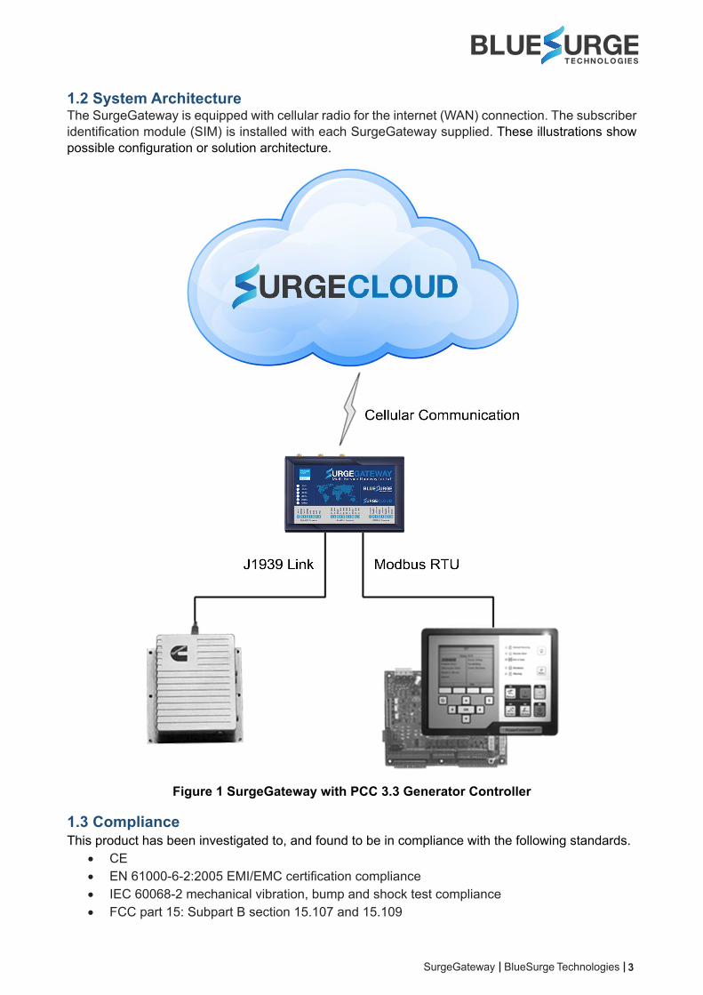
1.2 System ArchitectureThe SurgeGateway is equipped with cellular radio for the internet (WAN) connection. The subscriber identification module (SIM) is installed with each SurgeGateway supplied. These illustrations show possible configuration or solution architecture.
Figure 1 SurgeGateway with PCC 3.3 Generator Controller
1.3 ComplianceThis product has been investigated to, and found to be in compliance with the following standards.
• CE• EN 61000-6-2:2005 EMI/EMC certification compliance• IEC 60068-2 mechanical vibration, bump and shock test compliance• FCC part 15: Subpart B section 15.107 and 15.109

4
1.4 InstallationThis product is intended to be installed in accordance with the following regulatory agencies.
• LocalAHJ - Authority having Jurisdiction
• Underwriters laboratoriesUL/EN 61010-1 - The unit shall be installed in accordance electrical safety compliance
WARNING: InstallationImproper installation, maintenance, and lack of routine testing could result in malfunction.
1.5 Environmental RequirementsThis product must be installed in the following environmental conditions:
• Temperature range of -20°C to 70°C.• 93% ± 2% humidity non-condensing at 30°C.
The contents of this manual are important and must be kept in close proximity of the hardware. If asset ownership is changed, this manual and all other testing and maintenance information must also be passed to the current owner of the asset. A copy of this manual was shipped with the unit and is also available from the manufacturer.
1.6 SurgeGateway Interfaces and Electrical Specifications1.6.1 Power SupplyThe SurgeGateway works on +24VDC @65mA or +12VDC @130mA. It should be source from direct battery supply. The SurgeGateway has got surge and short circuit protection.
Table 1 Power Supply Specifications
Input voltage +12VDC or +24V DC (9VDC to 36VDC)Input current @ +24VDC 65mAInput current @ +12VDC 130mA
CAUTION: Power SourcesThe generator must be turned off and the system must be isolated from the high voltage AC or DC connections. Refer the safety instructions manual supplied by the generator supplier while installing the equipment.

5
1.6.2 RS485 Interface (for Modbus) The SurgeGateway provides a half-duplex RS485 interface as a Modbus slave device interfacing with signaling baudrates up to 115200.
Note: The user must remove the termination resistor in case it is not required.The electrical characteristics of the interface are:
Table 2 RS485 Electrical Specifications
Parameter Min. Typical Max. Units
Input common mode voltage -8 - 13 VDifferential input threshold -200 -125 -50 mVOutput common mode voltage - 1.5 3 VDifferential drive output, 54 Ω load
1.5 - - V
ESD ProtectionAir gap/human body model - ±15 - kVContact/air gap discharge - ±8 - kV
1.6.3 CAN 2.0B Interface (for SAE CAN J1939 Link)The SurgeGateway provides CAN Bus link layer interfaces for sending and receiving frames. The SurgeGateway supports controller area network interface with signaling rates up to 1 Mbps.
Note: The user must remove the termination resistor in case it is not required.
Table 3 CAN 2.0B Electrical Specifications
Parameter Min. Typical Max. Units
Input common mode voltage -7 - 12 VDifferential input threshold -6 - 6 VPeak to peak output common mode voltage
- 1 - V
Differential output voltage (dominant)
1.2 - 3 V
Differential output voltage (recessive) no load
-0.5 - 0.05 V
CANH or CANL -36 - 36 VESD Protection
Human body model* - ±16 - kV
* All electrical interfaces operate normally after being subjected to 8kV ESD contact discharge as per IEC 60945 and IEC 61000-4-3 human body model, level3
6
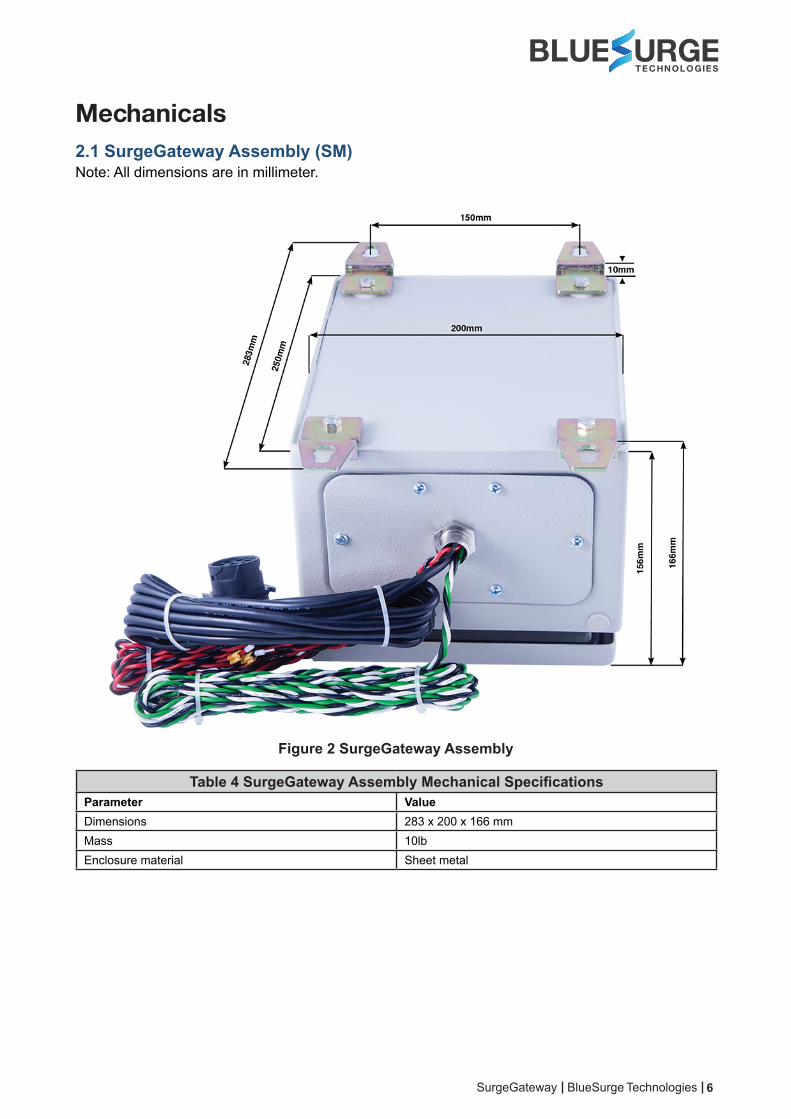
Mechanicals2.1 SurgeGateway Assembly (SM)Note: All dimensions are in millimeter.
Figure 2 SurgeGateway Assembly
Table 4 SurgeGateway Assembly Mechanical SpecificationsParameter ValueDimensions 283 x 200 x 166 mmMass 10lbEnclosure material Sheet metal

7
InstallationThe following section contains recommended installation guidelines for end users.
The installer is responsible for following all safety guidelines during product installation. Refer to the preface section for details.
The SurgeGateway uses very low power during transmission and therefore presents no radiation hazard during normal use, installation, testing, and troubleshooting.
WARNING: InstallationInstallation must be performed with engine powered off for successful discovery of the CAN Bus parameters.
3.1 Getting StartedGetting the SurgeGateway assembly ready for operation requires doing the following:
1. Prepare for the installation 2. Determine a suitable mounting location 3. Mount the SurgeGateway assembly4. Combo antenna mounting and guidelines (required only when the GSM signal is poor and/or GPS line of sight is not clear) 5. Protect the cable and cable connectors6. Connect to power 7. CAN Bus connection 8. Modbus connection
3.2 Prepare for the InstallationCheck that you have the items and tools listed below before installing the SurgeGateway assembly.
3.2.1 Shipping Box ContentsUnpack the contents of the shipping box and use the list below as a guide to check that you have received the items you ordered.
• SurgeGateway assembly in 250mm (L) x 200mm (W) x 150mm (H) NEMA 4, IP65, UL rated enclosure
• Mounting accessory kit (located inside the enclosure)• Installation guide (located inside the enclosure)• Subscriber identification module (SIM) inserted in the tray
3.2.2 Additional MaterialsYou may require some of the following materials to install SurgeGateway assembly on a mounting surface.
• Qty. 4 - M8.8 stainless steel bolt fasteners and nuts (for the SurgeGateway assembly)You may require some of the following materials to extend the antenna outside the equipment cabin (if GSM signal strength is poor in the location).
8
• Qty. 1 - 20mm stainless steel or PVC cable gland (for fastening the coaxial cable on top of assembly surface., where the antenna is fastened to the enclosure).
WARNING: Installation Improper installation or damage to the coaxial cable surface may impact GSM received signal strength
index of the SurgeGateway. Do not cut the RG176 coaxial cable for extending the antenna to a longer distance. It is recommended to use RG176 and SMA cable assembly for such installations.
3.2.3 Required ToolsYou may require the following tools to install the SurgeGateway assembly.
• Drill and drill bit M8• Socket wrench set• Screw driver for fastening signal wire• Wire stripper• Wire lugs (if required for DC source connection)
3.2.4 SurgeGateway IdentificationEach SurgeGateway has a unique serial number used by Bluesurge Technologies to register it on the device cloud. This is an alphanumeric identifier. The SurgeGateway serial number is located on the side section of the SurgeGateway and on the top cover of the enclosure (inside).
3.2.5 SurgeGateway Activation RequestIn order to enable diagnostic services you must activate the SurgeGateway by contacting support at 732 301 7090 . Please note the subject name should be with the serial number of the SurgeGateway.
3.3 Determine Suitable Mounting LocationBefore installing the SurgeGateway assembly, consider the important guidelines provided below.
It is very important for end users to install the SurgeGateway assembly in a safe and secure way to avoid danger or damage to persons or property. Do not mount or operate near flammable gases and fumes.
• Mount indoors, inside an asset housing, or in an area protected from environmental elements.
• Fasten the SurgeGateway assembly securely so that it is not loosened easily.
• Mount the SurgeGateway assembly on a surface that does not get hotter than the maximum operating temperature. If the surface may get hotter, mount the SurgeGateway assembly with a thermal barrier between it and the mounting surface.
• Mount the SurgeGateway assembly away from the alternator (as much as you can).
• Check that the SurgeGateway assembly cable reaches the power source, Modbus communication port and diagnostic link before you drill any mounting holes.
9
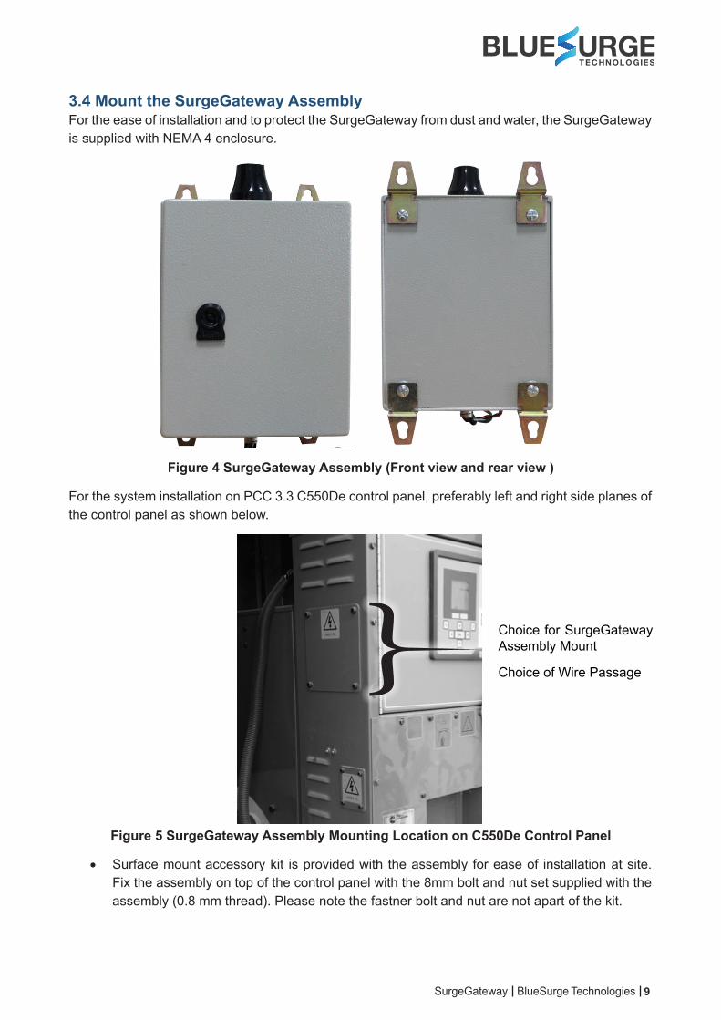
3.4 Mount the SurgeGateway AssemblyFor the ease of installation and to protect the SurgeGateway from dust and water, the SurgeGateway is supplied with NEMA 4 enclosure.
Figure 4 SurgeGateway Assembly (Front view and rear view )
For the system installation on PCC 3.3 C550De control panel, preferably left and right side planes of the control panel as shown below.
Choice for SurgeGateway Assembly Mount
Choice of Wire Passage
Figure 5 SurgeGateway Assembly Mounting Location on C550De Control Panel
• Surface mount accessory kit is provided with the assembly for ease of installation at site. Fix the assembly on top of the control panel with the 8mm bolt and nut set supplied with the assembly (0.8 mm thread). Please note the fastner bolt and nut are not apart of the kit.
10
• The SurgeGateway assembly has got wire harness with open wire terminals (crimped with 0.5mm end of line lugs). Take the wires inside the control panel (ideally through the air duct gap provided in the control panel.
3.5 Combo Antenna Mounting and GuidelinesGuideline 1: If the GSM signal strength is good and the asset is in an open area, it is not recommended to change or extend the combo antenna from the standard package.
It is always recommended to check the GSM signal strength before installing the equipment.
Guideline 2: If the GSM signal strength is not sufficient inside asset housing., extend the antenna out of the housing.
Cable management and connector strain relief must be incorporated in the installation. Secure the cable at regular intervals along its length as part of the installation to prevent cable wear and eliminate strain on the connector. Damage to the connector interface or cable may otherwise result and lead to hardware failure.
• Do not drill any holes before checking that you have room for the bend radius of the antenna cable.
• For reliable operation, do not go below a bend radius of 1.5 cm. • Mount on a surface that is free from dirt, grime, water and grease to avoid damaging the
mounting surface or the asset paint.• Ensure that the combo antenna is pointing towards the equator and its line of sight to the sky
is clear of obstructions.• Mount at least 20 mm from metal objects.
3.6 Protect the Cables and Cable Connectors
Cable management and connector strain relief must be incorporated in the installation. It is highly recommended securing the cable at regular intervals along its length as part of the installation to prevent cable wear and eliminate strain on the connector. Damage to the connector interface or cable may result in hardware failure.
To protect the SurgeGateway connector interface, follow the guidelines below:
• Apply tape around the cable ends to help in routing the cable.• Secure the cable such that it does not pull on the connector or strain the SurgeGateway
assembly connector.• Tie the cable down so that the weight of a vibrating cable does not stress or strain the
connection.• Tie the cable down using cable ties and tie holders at equal intervals along the cable route
to prevent chafing, wear, or strain.• Secure the cable tie holder with a self-tapping screw for best holder retention.
3.7 Connect to Power
Before applying power to the SurgeGateway, make sure that your power supply’s rated voltage complies with the recommended voltage range and also polarity.
• Locate the main power input and the ground (GND) wires from the SurgeGateway assembly harness details (Color code: Red – DC +, Black: DC -) (refer the schematic in appendix B).
• Identify direct battery supply terminals located inside the control panel. The device must be connected to the direct battery terminals (not switched output of the source).
• Ensure that the main power input and ground wires reach the asset DC power distribution panel.If the wires are not long enough, splice similar SWG grade or better wires to the main power input and ground wires so that they reach the fuse panel. Cover any splices with adhesive lined heat shrink.
• Correctly mate the power cable before applying power.
3.8 CAN Bus Connection
The asset must be turned off and the system must be isolated from the high voltage AC or DC connections and also rotating equipment. Refer the safety instructions manual supplied by the generator supplier while installing the equipment.
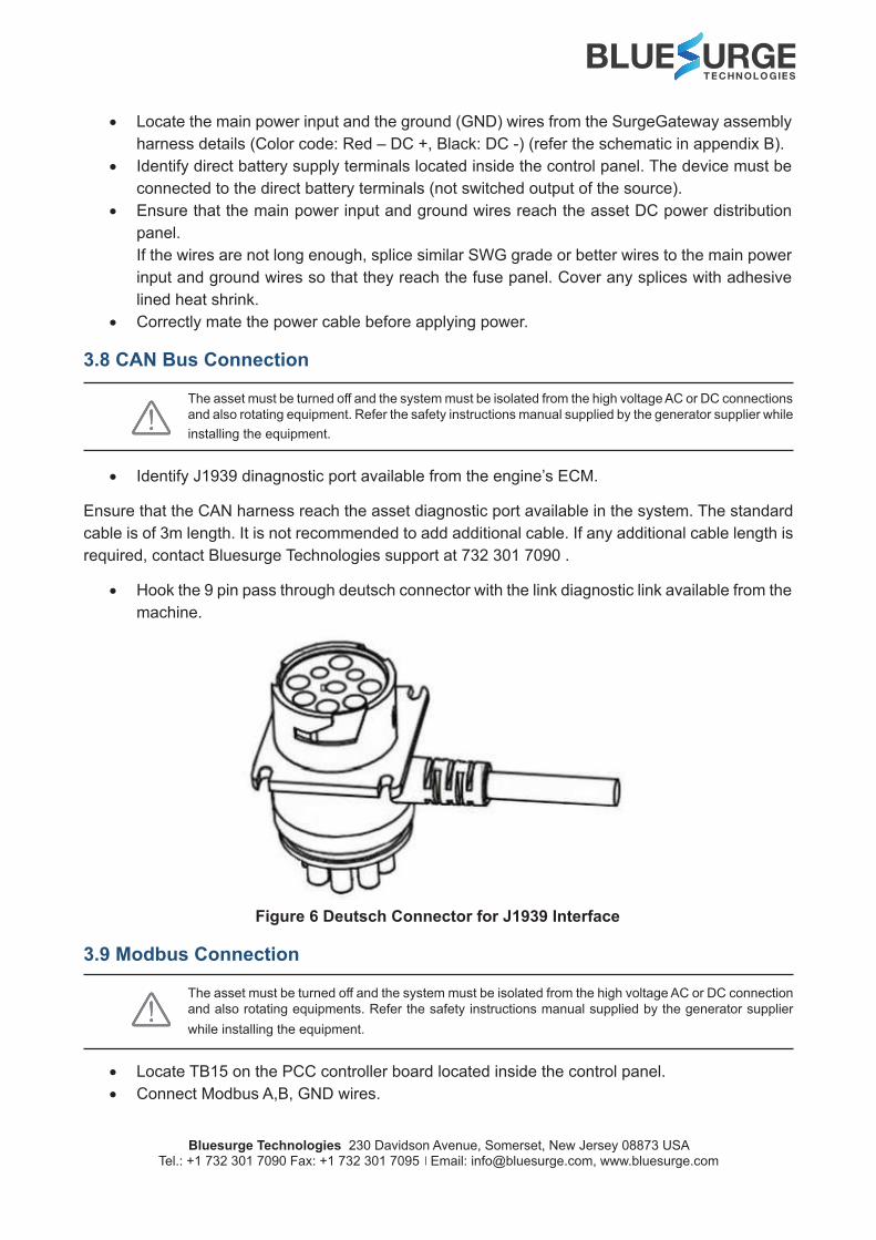
• Identify J1939 dinagnostic port available from the engine’s ECM.
Ensure that the CAN harness reach the asset diagnostic port available in the system. The standard cable is of 3m length. It is not recommended to add additional cable. If any additional cable length is required, contact Bluesurge Technologies support at 732 301 7090 .
• Hook the 9 pin pass through deutsch connector with the link diagnostic link available from the machine.
Figure 6 Deutsch Connector for J1939 Interface
3.9 Modbus Connection
The asset must be turned off and the system must be isolated from the high voltage AC or DC connection and also rotating equipments. Refer the safety instructions manual supplied by the generator supplier while installing the equipment.
• Locate TB15 on the PCC controller board located inside the control panel. • Connect Modbus A,B, GND wires.