surge protection · pdf filetable 4 – scenario i tests for spds intended for location...
TRANSCRIPT

Schutzvermerk / Copyright-Vermerk
Surge Protection 2013
Presented by: Ken PittTPS3 Product Manager

Page 2
Agenda
• Surges: causes & effects• How a TVSS/SPD works• Industry standards• Specifying SPDs• Products

Page 3
What Is a Surge/Transient?• High amplitude, short duration overvoltage• Can be positive or negative polarity• Can be from energized or grounded conductor
Transient OvervoltageCan be thousands of volts
Millionths of second

Page 4
What Causes Surges/Transients?• Lightning• Switching:
• Load Switching – utility & customerMotors, Large Loads, Faults, Fuse Operation
• Source Switching• Smart Grid, Gensets, PV, Wind Turbine
• Internally generated surges: ≈70%• Externally generated surges: ≈30%
In outdoor environment, this ratio probably reverses
Remember Differential Equations?Solved for steady-state solution and
transient solutionMath: v(t) = 3te-2t + 2t – 1
transient

Page 5
Effects of Transient Voltages?
• Microelectronics Intolerant to Surges• Disruption
• Lockups, Downtime & Interruption costs• Computing glitches and errors
• Degradation• Microelectronics• Slow & continuous damage to motor
insulation• Destruction
• Failed microelectronics, ballasts,motors, controllers, etc.
Maybe analogous to:- ‘Water hammer’ in a plumbing system- ‘Rust’ to microelectronics

Page 6
Surge Suppressors
• A SPD, TVSS or Surge Suppressor will Not effectively control:• Utility “swells” lasting
several cycles • Utility “sags”• Harmonics• Certain noise problems• Not a substitute for
Lightning Protection System
• Will not save energy or lower utility billing

Page 7
Power Quality Tolerance Curve
Equipment will tolerate 500% overvoltage for 100s
5 x 120V = 600Vrms
600Vrms x 1.414 = 850Vpeak
Goal is to reduce transient overvoltages to tolerable level – in this case 850Vpeak
Page 8
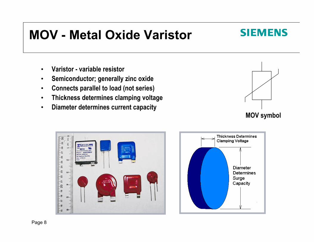
MOV - Metal Oxide Varistor
• Varistor - variable resistor• Semiconductor; generally zinc oxide• Connects parallel to load (not series)• Thickness determines clamping voltage• Diameter determines current capacity
MOV symbol

Page 9
MOV - Metal Oxide Varistor
• MOV seeks to equalize overvoltage diverted through MOV as current
• Voltage sensitive conductor: V = IR & I = V/R
• At ‘low’ voltages: very high impedance, 109: I 0A
• Above ‘threshold’ voltage: resistance approaches 0: I = high A
Current diverts through MOV as I = V/R (high V, low R)
• MOV does not ‘absorb’ surge, however, I2R heat is retained
• Bidirectional – Operates same for positive or negative surges
• Creates a momentary short-circuit to pass transient energy to earth; analogous to water heater pressure relief valve
+-+ -
+-+ -
Normal voltage
I = V 120VR 109
= 0.12A
Trivial leakage current
Normal voltage
I = V 120VR 109
= 0.12A
Trivial leakage current
Overvoltage
I = V 6000VR 1
= 6000A
Surge Current
Overvoltage
I = V 6000VR 1
= 6000A
Surge Current

Page 10
SPD Operation
MOV/SPD Acts as a momentary ‘short circuit’ ‘short circuit’ ≈ no overvoltage ≈ protected load
Load 1Load 2
Load 3Load 4
Load 5

How Surges Propagate
Internal or External?
ExternalSPD
InternalSPD

Page 12
Modes of Protection• ‘Mode of Protection’ is a surge path• MOVs equalize potential
across either side of MOV• Various ways to connect MOVs,
i.e., various Modes of Protection• L-N• L-G• N-G• L-L
• IEEE recommends defining modes: L-N, L-G, N-G, etc. (because ‘Common Mode’ and ‘Normal Mode’ mean different things to different folks)
• True 10-Mode Protection provides directly connected L-L MOVs
SPD/TVSS Terminology
= Parallel MOVs
A B C N G
Page 13
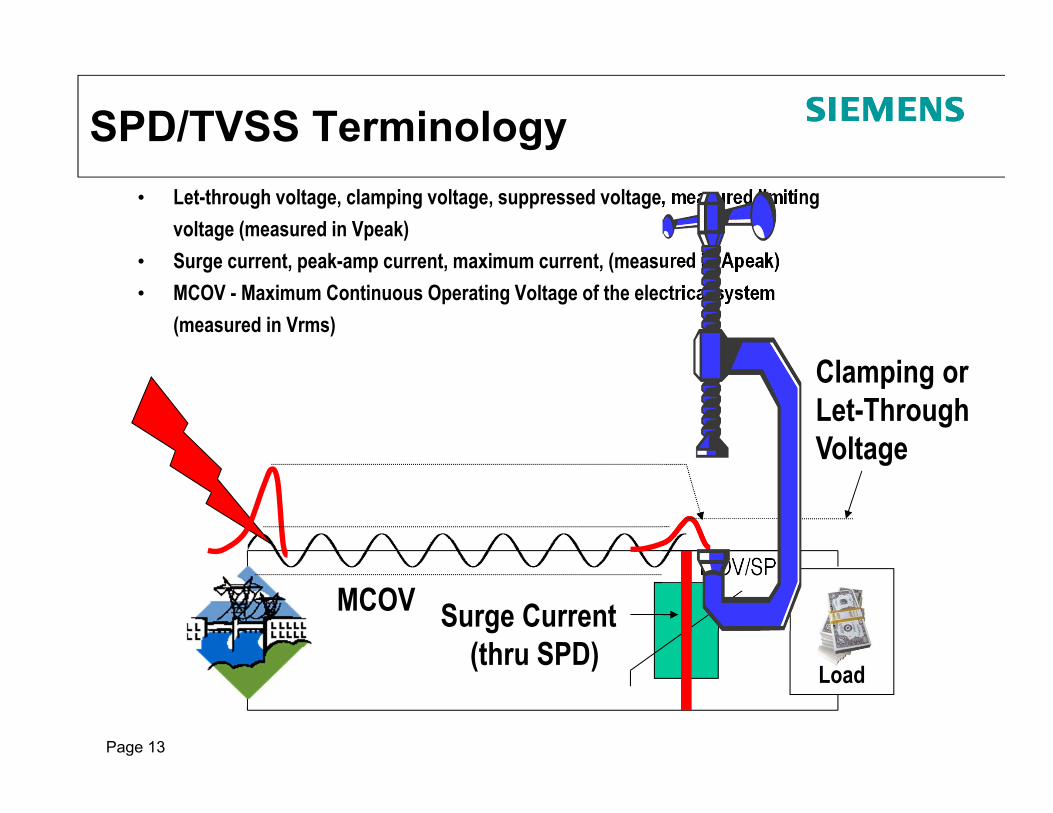
SPD/TVSS Terminology• Let-through voltage, clamping voltage, suppressed voltage, measured limiting
voltage (measured in Vpeak)• Surge current, peak-amp current, maximum current, (measured in Apeak)• MCOV - Maximum Continuous Operating Voltage of the electrical system
(measured in Vrms)
Load
Surge Current(thru SPD)
MOV/SPD
Clamping or Let-Through Voltage
MCOV
Page 14
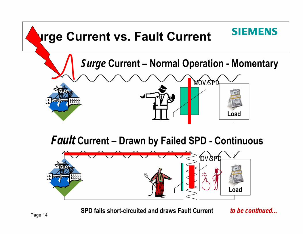
Surge Current vs. Fault Current
Load
MOV/SPD
Surge Current – Normal Operation - MomentaryMOV/SPD
Fault Current – Drawn by Failed SPD - Continuous
SPD fails short-circuited and draws Fault Current
Load
to be continued…

Page 15
Load
MOV/SPD
Current
‘Lower’ Fault Currents (0-20A)
‘Intermediate’ Fault Currents (20-1000A)
‘Higher’ Fault Currents (>1000A)
Tim
e
MOV Failure Intensity Increases With The Amount of Fault Current Drawn by the MOV

Page 16
SPD Overcurrent Protection Flaws
•Cannot assume MOV to fault at low impedance, and draw enough fault current to open fuse:1.) OCP needs low enough
rating to open, and2.) OCP needs to open
before MOV ruptures
�
time
MOV(s) can fail short here
Then, MOV(s) can overheat & rupture before OCP clears
Suppose Fuse clears here (after a few cycles)
500A test

Page 17
UL 1449 THIRD Edition
Combine TVSS and Surge Arresters into one UL Standard, UL 1449 3rd Edition renamed: Surge Protective Devices (SPDs)Effective: Sept 29, 2009
SPD
TVSSSurge Arresters
• New SPD Types: Types 1, 2, 3, 4 (& 5)• New Voltage Protection Ratings (VPRs) replace
old-style Suppressed Voltage Ratings (SVRs)• New I nominal ratings• Bid Specifications become Obsolete as product
evaluation & ratings change(Expensive big deal to manufacturers)

Page 18 18
UL 1449-3 & NEC Art. 285
• Changed term TVSS to SPD
TVSS SPDAligns with IEC, EN and international usage of term ‘Surge Protective Device’
• Old-style Surge Arrestors are now gone
• Creates Types 1, 2, 3, 4 (& 5) SPDs
X X

Page 19
UL 1449-3 & 2011 NEC Art 285SPD Types: Types 1, 2, 3 & 4 Based on Location within electrical distribution system
Trans
MeterSvc. Disc.
Panel
10m (30feet)
Type 2
Type 3
Type 1
OCP built in to SPD, more rigorous testing
Type 4 (Component) tested to Type 1or Type 2

Page 2020
UL 1449-3
Performance Test Format Changed New Testing uses Six (6) Times More Energy
Old – 6kV / 500ASuppressed Voltage Ratings
(SVR)
New – 6kV / 3,000A Voltage Protection Ratings
(VPR)
500A
3000A• As surge amplitude goes up,clamping voltage goes up too
• Specs become obsolete• Need new VPRs in specs
More For Reference now that Standard is 3+ years in use

Page 21 21
UL 1449-3
I nominal Testing – In - (Nominal Discharge Current)- New Concept to USA – Originated from IEC 61643- Duty Cycle Testing- 15 8x20s surges through every mode of three
samples used for VPR testingType 1 – 20kA or 10kAType 2 – 20kA, 10kA, 5kA or 3kAType 3 – 3kA or NoneType 4 – Based on intended usage as Types 1, 2 or 3
UL 96A Master Label requires 20kA In from Type 1 or Type 2 SPD

Page 22 22
NEC – Key Points
“285.3 Uses Not Permitted. An SPD (surge arrester or TVSS) shall not be installed in the following:
On ungrounded systems, impedance grounded systems, or corner grounded delta systems unless listed specifically for use on these systems.”
“285.5 Listing. An SPD (surge arrester or TVSS) shall be a listed device.”
285.6 - “The SPD (surge arrester or TVSS) shall be marked with a short circuit current rating and shall not be installed at a point on the system where the available fault current is in excess of that rating. This marking requirement shall not apply to receptacles.”

Page 23
2011 NEC - SPD Connector Leads
� Need short lead lengths!
� NEC 285.12: “The conductors used to connect the SPD (surge arrester or TVSS) to the line or bus and to ground shall not be any longer than necessary and shall avoid unnecessary bends”
� Industry typically states: Each foot of conductor adds 100 - 170V to clamping voltage
� No Sharp bends or kinks
� No Wire Nuts!
� Right Hand Rule – can cancel inductive effects by bundling, tie-wrapping conductors together

Page 24 24
2011 NEC Article 708
708.2 Definitions:Critical Operations Power Systems (COPS). Power systems for facilities or parts of facilities that require
continuous operation for the reasons of public safety, emergency management, national security or business
continuity.
708.20(D) Surge Protective Devices. Surge protective devices shall be provided at all facility distribution voltage
levels.
Only NEC article mandating SPD(s) installation

Page 25 25
Verifying SCCRs (for NEC 285.6 compliance)
• Appropriate wording on SPD’s UL label:“Suitable For Use on a Circuit Capable of Delivering
Not More Than 200kA, 600 Volts Max.”
Appropriate wordingin UL File:

Page 26 26
UL Listing requires 30A RK5 fuses, but installer likely to use 30A breaker.
Breakers tend to clear slower than fuses
In event of problem with wrong overcurrent protection, who becomes responsible?
Protecting Engineer of Record

Page 27 27
MSB specified as 4,000A & 65kAIC
SPD quote to distributor for SPD with 5kA SCCR
MSB specified as 4,000A & 65kAIC (available fault current unknown but likely more than 5kA)
Can Engineer catch this at submittal stage?
Protecting Engineer of Record

Page 28 28
It takes 10kV to push a 10kA surge, 10 meters (0.1/m)It takes 27kV to push a 10kA surge, 30 meters (0.09/m)It takes 45kV to push a 10kA surge, 50 meters (0.09/m)
Voltage becomes so high that it flashes over upstream, so surge current is not pushed as hard
10,000V
27,000V
45,000V
‘Inductance Police’
A B CPanel
Similar to shooting fire hose through soda straw – won’t all go!
L - slight inductance of wire
10m
30m
50m
How Large are Surges?IEEE Research

Page 29
IEEE C62.41.2 - 2002“Expected voltages and current surges”
Location Categorya
Peak Valuesd
Effective Impedance ()Voltage(kV)
Current(kA)
A 6 0.5 12f
B 6 3 2
Table 3 – Standard 1.2/50s – 8/20s Combination WaveExpected voltages and current surges in Location Categoriesa A and Bb
Single-phase modesc : L-N, L-G and [L&N]-GPolyphase modes: L-L, L-N, L-G and [L’s]-G
(See Table 5 for N-G modes)
Table 4 – Scenario I tests for SPDs intended for Location Category C3
Exposure
Standard tests Optional test
1.2/50µs Voltage generator 8/20µs Current generator
100kHz Ring Wave for front-of-wave response
evaluationMinimum open-circuit voltage to be
applied to SPDCurrent to be driven through the
SPDb
Low 6kV 3kAc 6kV
High 10kV 10kA 6kV

Page 30
Selecting kA Ratings• Realistic kA Per Phase ratings:
Service Entrance: 200kA-300kA per phaseDistribution: 100kA-200kA per phasePoint of Use: 50kA-100kA per phase
kA buys redundancy - up to a point
Not carved in stone:Consider upsizing at critical loads, larger panels, outdoor loads, isokeraunic activity, etc.
Consider downsizing based on value, budget, etc.
• Specific Modes? L-N, L-G, N-G, L-LTire Tread Analogy:• Thicker the tread, the longer it lasts & harder to get a nail through• Bigger SPDs are more robust and withstand more abuse
MOVs
A B C N G
= Parallel MOVs
MOVs
MOVs
MOVs
MOVs
MOVs
MOVs
MOVs
MOVs
MOVs
MOVs MOVsMOVs
A B C N G
= Parallel MOVs
MOVsMOVs
MOVsMOVs
MOVsMOVs
MOVsMOVs
MOVsMOVs
MOVsMOVs
MOVsMOVs
MOVsMOVs
MOVsMOVs
MOVsMOVs

Page 31
Siemens Solution
•Becoming popular in SPD industry•Large 34mm sq. MOV•TPMOV Optimizes Thermal Protection to double-function as Overcurrent Protection•Each MOV is individually fused•Robotized assembly minimizes tolerances between fuses, MOVs, and thermal disconnectors (more consistent)•TAC switch allows for individual monitoring of each MOV
A B C
NG
TranSafe

Page 32
SIEMENS TPS3 SPDs• Integral - UL 1449 Recognized/Listed and
Labeled• External – UL 1449 Listed and Labeled• UL 1283 Recognized• Integral - Type 4 tested as Type 1 or 2 (TPS3
05 - Type 1 or 2)• External - Type 1 or 2 SPD• 20kA I-nominal• 200kA Short Circuit Current
Ratings (SCCR)• Low UL 1449 Voltage Protection Ratings
(VPRs)• Surge Current Ratings from
50kA up to 1000kA• Standard 7 modes of protection
� True 10 mode protection available• Full selection of options: Internal
disconnect switch, Dry Contacts, Surge Counter, etc.

Page 33
TPS3 03 DC
�UL Listed to UL 1449-3 PV Standard
�Network Voltages – 300V, 600V, and 1000V
�UL 1449 tested SCCR: 100kA DC
�Max Surge Current: 50kA per Mode
�UL 1449 tested In: 20kA
�Type 1 SPD
�UL 96A Lightning Protection Master Label eligible
�Phase Loss Monitoring (toggles LED & Dry Contacts)
Page 34 34
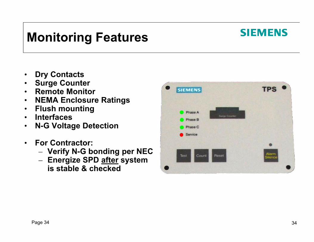
• Dry Contacts• Surge Counter• Remote Monitor• NEMA Enclosure Ratings• Flush mounting• Interfaces• N-G Voltage Detection
• For Contractor:– Verify N-G bonding per NEC– Energize SPD after system
is stable & checked
Monitoring Features

Page 35 35
Simplifying Suggestions
• Select UL 1449-3 Listed SPD having ‘UL Mark’• Select SPD with 20kA In rating• Select high Short Circuit Current Rating (SCCR)• Select low Voltage Protection Ratings (VPRs)• Select Type 1 SPD• Ensure short leads

Page 36
Key Specification Parameters• Realistic kA Per Phase ratings:
– Service Entrance: 300-200kA, maybe 200-150kA outside Gulf rim states
– Downstream: 200-100kA– Branch: 100-50kA– kA buys redundancy - up to a point
• Specific Modes? L-N, L-G, N-G, L-L• Noise Filtering: -50dB @ 100kHz• Safety Related: Thermal Cutouts & MOV size• Submittal requirements – UL File (needed to
confirm SCCR, which is not posted @ ul.com) & clearly identify Overcurrent Protection
• External Mount Considerations– 24” or less leads - have Contractor try to meet this. – Gently twist leads – Indicate Contractor can move SPD breaker in panel– Disconnect means for servicing and overcurrent
protection
Page 37
SIEMENS Here to Help
� Application Assistance � Training� Sounding Board for issues� Competitive crosses or analysis� General Help� On-Line Live Support� Forensic Testing & Analysis of failed
SPDs� Etc.