surftest sj-410 series - metrologia.pt · when the sj-410 series detector is mounted on the manual...
TRANSCRIPT

PRE1387
SURFTEST SJ-410 SERIES
FORM
MEA
SURE
MEN
T
PORTABLE SURFACE ROUGHNESS TESTER EVOLUTION.

2
Portable Surface Roughness Tester Evolves!
Colour-graphic LCD The colour-graphic LCD with excellent visibility displays calculated results and assessed profiles even clearer. This is really useful for checking results without printing them out.
The display interface supports 16 languages.
Touch screen for easier operationsThe screen display can be switched between icon display and text display. Successfully realizes operability with utility and usability.
Backlight providedA backlight improves usability in dim testing environments.
Easy to use and highly functionalThis portable surface roughness tester is equipped with analysis functionality rivaling that of benchtop surface roughness testers.
Complies with many industry standards The Surftest SJ-410 complies with the following standards: EN ISO, VDA, JIS, ANSI as well as customized settings.
Applicable standardsEnhanced power for making measurements on site
Multilingual support
Icon display
Data compensation Simple contour analysis function
Text display
A wide range, high-resolution detectorMeasuring range / resolution 800 µm / 0.0125 µm 80 µm / 0.00125 µm8 µm / 0.000125 µm
High straightness drive unitStraightness / traverse length 0.3 µm / 25 mm (SJ-411) 0.5 µm / 50 mm (SJ-412)
High accuracy measuring
SJ-411
SJ-412

3
The Large Touch-screen, Colour-graphic LCD Ensures Both Intuitive Control and Advanced Operability
Memory card (optional) is supportedThe measurement conditions and data can be stored in a memory card (optional) and recalled as required. This enables batch analysis and printout of data after on-site measurement.
•Measurement condition I nternal memory: 10 sets Memory card: 500 sets
•Measurement result Memory card: 1000 sets
A variety of interfaces supplied as standard The external device interfaces that come as standard include USB, RS-232C, SPC output and footswitch I/F.
Access to functions can be restricted by a passwordA pre-registered password can limit use of measurement conditions and other settings to the tester’s administrator.
The unit is easily transported in a dedicated carrying case which includes holders for the accessories as well as the tester itself (standard accessory).
Interfaces Data storage
Password protection
Carrying case
High-speed printer prints out measurement results on siteA high-quality, high-speed thermal printer prints out measurement results. It can also print a BAC curve or an ADC curve as well as calculated results and assessed profiles. These results and profiles are printed out in landscape format, just as they appear on the color-graphic LCD.
Printer
Single button measurements A sturdy sheet-button panel with superior durability in any environ-ment is provided. For repeat measurement of the same work, simply pressing the start switch can complete measurement, analysis and printout.
Sheet buttons
→

4
Enhanced Measuring Functions
• Skidless measurementSkidless measurement is where surface features are measured relativeto the drive unit reference surface. This measures waviness and finelystepped features accurately, in addition to surface roughnness, butrange is limited to the stylus travel available. The SJ-410 series supportsa variety of surface feature measurements simply by replacing thestylus.
The height/tilt adjustment unit comes as standard for leveling the drive unit prior to making skidless measurements and, supported by guidance fromthe unique D.A.T. function, makes it easy to achieve highly accurate alignment.
When the SJ-410 Series detector is mounted on the manual column stand*1 for measurement, it can be combined with any of the optional products for easier leveling: leveling table*1, 3-axis alignment table*1 or tilt adjustment unit*1.
• Height/tilt adjustment unit (standard accessory)
• Skidded measurementIn skidded measurements, surface features are measured with referenceto a skid following close behind the stylus. This cannot measurewaviness and stepped features exactly but the range of movementwithin which measurement can be made is greater because the skidtracks the workpiece surface contour.
Patent registered in Japan, U.S.A.. Patent pending in Germany
Patent registered in Japan, U.S.A.. Patent pending in Germany
Your choice of skidless or skidded measurement
Powerful support for leveling
Measuring example of stepped features: Skidded
測 定
測定データ
Measured profileMeasured profile
Fulcrum point of StylusStylus
DetectorTraverse direction
測 定
Fulcrum point of StylusStylusSkid
Detector Fulcrum point of SkidTraverse direction
測 定
Traverse direction
測 定
Traverse direction
測 定
Traverse direction
測 定
Measuring example of stepped features: Skidless
Preliminary measurement Amount of tilt adjustment
Tilt adjustment knobHeight / tilt adjustment unit
*1: For details about optional products, see P6-7.
Height adjustment knob
With DAT
With DAT
Preliminarymeasurement
DAT screen(adjustmentamount)
OK
NG
Final measurementPreliminary
measurementIntuitive adjustment
using the tilt adjustment knobWithoutDAT
WithoutDAT
Repeat

5
Previously measured data can be recalculated for use in otherevaluations by changing the current standard, assessed profile androughness parameters.
This function allows a sampling length to be arbitrarily set in 0.01 mm increments (SJ-411: 0.1 mm to 25 mm, SJ-412: 0.1 mm to 50 mm). It also allows the SJ-410 series to make both narrow and wide range measurements.
Point group data collected for surface roughness evaluation is used to perform simplified contour analysis (step, step height, area and coordinate variation). It assesses minute forms that cannot be assessed by a contour measurer.
An “OK/NG” judgment symbol is displayed when limits are set for the roughness parameter. In case of “NG,” the calculated result is highlighted. The calculated result can also be printed out.
This function samples stylus displacement for a specified time without engaging detector traverse, which enables use as a simplified vibration meter or displacement gage incorporated in another system.
Surface roughness measurement requires a run-up distance beforestarting the measurement (or retrieving data). When the SJ-410 Series measures, its run-up distance is normally set to 0.5 mm. This distance, however, can be shortened to 0.15 mm using the narrow part measurement function (starting from the origin point of the drive unit). The function extends the possibility of measurement of narrow locations such as grooves in piston ring / O-ring mounts.
Usually, a spherical or cylindrical surface (R-surface) cannot be evaluated, but, by removingthe radius with a filter, R-surface data is processed as if taken from a flat surface.
A single measurement enables simultaneous analysis under two different evaluation conditions. A single measurement allows calculation of parameters and analysis of assessed profiles without the need for recalculation after saving data, contributing to higher work efficiency.
Patent pending in Japan
Recalculating
Arbitrary sampling length setting
Simple contour analysis function
GO/NG judgement function
Real sampling
Narrow space measuring function
Assessing a single measurement result undertwo different evaluation conditions
More measuring functions than expected from a compact tester
R-Surfacecompensation
R-Surfacecompensation
The “OK” symbol means the measurement is within the limits set; “NG” means it is not, in which case an arrow points to either the upper or lower limit in the printout.
Step
Dimensions
Step volume
Coordinate difference
3.5
0.5
0.5 2.5
0.1
Example: surface roughness measuring of piston-ring groove
Example: surface roughness measuring of mounting groove for O-ring
Overruns surface using 0.5 mm run-up
Run-up of 0.5mm is not enough for performing the measurement
Evaluation lengthλc=2.5 mm1 sampling length
Evaluation lengthλc=0.8 mm1 sampling length
2.5
ø1.2
1.3Stylus
Workpiece
Normal run up: 0.5 mm
Run up for narrow parts : 0.15 mm 1.
8
The run-up distance can be shortened to 0.15mm by measuring from the origin point.
•Narrow space measuring Typical applications

6
Optional Accessories
Can be adjusted to match the height of the item to be measured.
Three new optional products are available to be attached to the manual column stand (No.178-039). You can choose the unit that suits your application. Or, you can also use the three products in any combination. Using the optional units makes SJ-411/412 more convenient and easier to use to ensure accurate measurements.
Simple column stand
Options for simple column stand
No.178-039Vertical adjustment range: 250 mmDimensions: 400 × 250 × 578 mmMass: 20 kg
Auto-set unit* – 178-010This unit enables the vertical (Z-axis) direction to be positionedautomatically (auto-set function). A single button operation completes a series of operations from measurement, saving and auto-return (saving and auto-return can be switched on and off by operating the drive unit).
X-axis adjustment unit* – 178-020This unit helps fine-tune the horizontal (X-axis) direction.
Tilting adjustment unit* – 178-030This unit is used for aligning the workpiece surface with the detectorreference plane. It supports the DAT function to make the leveling ofworkpiece surfaces easier.
Preliminary measurement
Tilt adjustment
10m
m
±1.5°
* Cannot be used when the tester’s main unit is an older model (SJ-401/402).
Complete set of optional units for the manual column stand
Tilting adjustment unit
X-axis adjustment unit
Auto-set unit
12.5 mm 12.5 mm
Example of mounting on simple column stand
12
250
25(50)
12040
6057
8
175(201.5)
40
250400
Code No.178-039 簡易スタ ンド外観寸法図
*The dimensions in parentheses indicate those for SJ-412
Measuring range
15
8.5
7 11
T-groove dimensions
Unit: mm

7
XY leveling tables Precision vise
Cylinder attachment Reference step specimen
This table helps make the alignment adjustments required when measuring cylindrical surfaces. The corrections for the pitch angle and the swivel angleare determined from a preliminary measurement and the digimatic micrometers are adjusted accordingly. A flat-surfaced workpiece can also be leveledwith this table.
The leveling table can be used to align the surface to be tested with the detector reference plane. The operator is guided through the procedure by screen prompts.
3-axis adjustment table: 178-047
DAT function for the optional leveling table
The table includes X- and Y-axes micrometer heads. This makes axis alignment much easier because the tilt adjustment center is the same as the rotation center of the table. (Code No.178-042-1/178-043-1)
This block can be positioned on top of cylindrical objects to perform measurements.No.12AAB358Diameter: ø 15~60 mm Configuration:• Cylindrical measurement block• Auxiliary block• Clamp
Used to calibrate detector sensitivity.No.178-611Step nominal values: 2 µm /10 µm
Aligned Not aligned
Axial line
End point
Axial line
End point
Start pointStart point
Recorded profiles
Traverse directionTraverse direction
DAT screen guides the user when leveling
Digimatic micrometer head
Amount of micrometer head adjustment required
Leveling table (DAT)(option)
No.178-048Inclination adjustment angle: ± 1.5°Table dimensions: 130 × 100 mmMaximum load: 15 kg
Fits on the stand.
Application
178-042-1(Movement is in X- and Y-axes only.)
178-049
*Drive unit not included.
7
43
13
T-groove dimensions
Order No. 178-042-1(mm) 178-052-1(inch)
*with digital heads
178-043-1(mm) 178-053-1(inch)
*with analog heads
178-049(mm) 178-058(inch/mm)*with digital heads
Table dimensions 130 × 100 mmMaximum load 15 kgInclination adjustment angle
±1.5° —
Swiveling angle ±3° —X/Y-axis travel range ±12.5 mm ±12.5 mm ±12.5 mmResolution 0.001 mm 0.01 mm 0.001 mmDimensions (WxDxH) 262 × 233 × 83 mm 220 × 189 × 83 mm 262 × 233 × 55 mmMass 6.3 kg 6 kg 5 kg
Order No. 178-019Clamping method Sliding jawsJaw opening 36 mmJaw width 44 mmJaw depth 16 mmHeight 38 mm
Patent registered in Japan, U.S.A.. Patent pending in Germany
Patent registered in Japan, U.S.A.. Patent pending in Germany
8
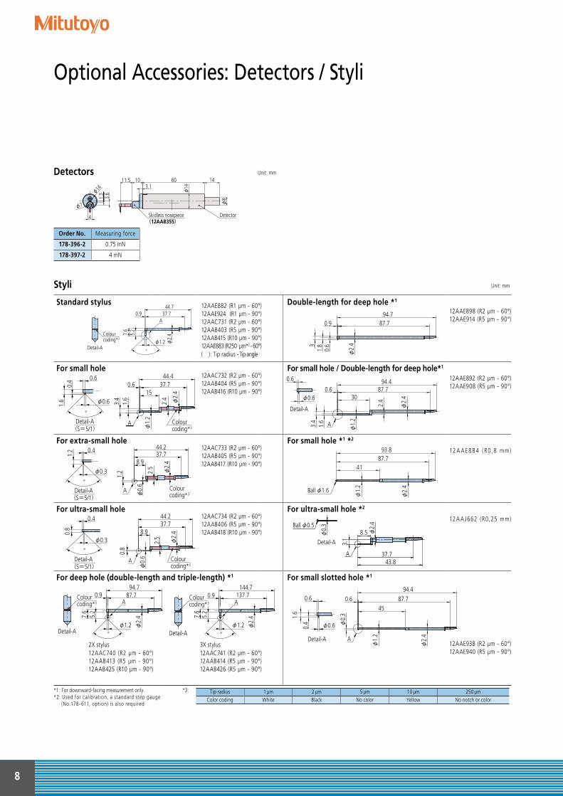
Optional Accessories: Detectors / Styli
Unit: mm
Unit: mm
Detectors
Styli
Order No. Measuring force
178-396-2 0.75 mN
178-397-2 4 mN
1460
φ8
φ14
Detector
φ14
φ7
1011.53.1
3.6
1.3
Skidless nosepiece(12AAB355)
4
Standard stylus 12AAE882 (R1 µm - 60°)12AAE924 (R1 µm - 90°) 12AAC731 (R2 µm - 60°)12AAB403 (R5 µm - 90°) 12AAB415 (R10 µm - 90°)12AAE883 (R250 µm*2 - 60°)( ): Tip radius - Tip angle
Double-length for deep hole *1
12AAE898 (R2 µm - 60°)12AAE914 (R5 µm - 90°)
For small hole12AAC732 (R2 µm - 60°) 12AAB404 (R5 µm - 90°)12AAB416 (R10 µm - 90°)
For small hole / Double-length for deep hole*1
12AAE892 (R2 µm - 60°)12AAE908 (R5 µm - 90°)
For extra-small hole12AAC733 (R2 µm - 60°)12AAB405 (R5 µm - 90°)12AAB417 (R10 µm - 90°)
For small hole *1 *2
12 A A E8 8 4 (R0, 8 mm)
For ultra-small hole12AAC734 (R2 µm - 60°)12AAB406 (R5 µm - 90°)12AAB418 (R10 µm - 90°)
For ultra-small hole *2
12A A J662 (R0,25 mm)
For deep hole (double-length and triple-length) *1 For small slotted hole *1
12AAE938 (R2 µm - 60°)12AAE940 (R5 µm - 90°)
2X stylus12AAC740 (R2 µm - 60°)12AAB413 (R5 µm - 90°)12AAB425 (R10 µm - 90°)
3X stylus12AAC741 (R2 µm - 60°)12AAB414 (R5 µm - 90°)12AAB426 (R5 µm - 90°)
*1: For downward-facing measurement only. *2: Used for calibration, a standard step gauge (No.178-611, option) is also required
小穴用
Colourcoding*3
Detail-A
0.6
0.4
1.6 φ0.6
°
(S=5/1)
φ2.
415
φ1.
2
3.4
2.4
1.6
0.6 37.744.4
A
極細穴用
Colourcoding*3
Detail-A
0.4
1.2
φ0.3
°
(S=5/1)
φ2.
48.9
φ0.
6
2.5
37.7
1.2
44.2
A
超小穴用
Colourcoding*3
Detail-A
φ0.3
°
0.8
0.4
(S=5/1)
φ2.
4
37.7
2.5
φ0.
6
8.9
44.2
0.8
A
深穴用
Colourcoding*3
Colourcoding*3
Detail-A Detail-A
φ2.
4
87.70.9
φ1.2°
94.7
7.6
5.2
A
φ2.
4
137.70.9
7.6
144.7
φ1.2°
5.2
A
深穴2倍用
31.
80.
6
φ2.
4
94.787.70.9
小穴用・深穴2倍
φ1.
2
1.6
3.4
2.4
φ2.
4
94.487.70.6
30
A
0.6
φ0.6
Detail-A
細穴形状用
φ1.
2
φ2.
4
Ball φ1.6
4187.7
93.8
極細穴形状用
φ2.
4φ0.
3
A
7
37.743.8
7
Ball φ0.5
Detail-A
φ2.
4
43.837.7
8.5
3.1
A
φ0.
3Ball φ0.5
Detail-A
細長穴用
φ0.
3
0.4
1.6
φ1.
2
φ2.
4
94.487.70.6
45
A
φ0.6
0.6
Detail-A
*3 : Tip radius 1 µm 2 µm 5 µm 10 µm 250 µmColor coding White Black No color Yellow No notch or color
標準スタイラス
°
0.9 37.7
7.6
44.7
φ2.
4
φ1.2
5.2
A
Colourcoding*3
Detail-A

9
Unit: mmStyli
For deep groove(10 mm)12AAC735 (R2 µm - 60°)12AAB409 (R5 µm - 90°)12AAB421 (R10 µm - 90°)
For deep groove *1 (20 mm)12AAE893 (R2 µm - 60°)12AAE909 (R5 µm - 90°)
For deep groove*1 (20 mm) 12AAC736 (R2 µm - 60°)12AAB408 (R5 µm - 90°)12AAB420 (R10 µm - 90°)
For deep groove *1
(40 mm) 12AAE895 (R2 µm - 60°)12AAE911 (R5 µm - 90°)
For deep groove*1 (30 mm) 12AAC737 (R2 µm - 60°)12AAB407 (R5 µm - 90°)12AAB419 (R10 µm - 90°)
For deep groove (30 mm) / Double-length for deep hole *1
12AAE894 (R2 µm - 60°)12AAE910 (R5 µm - 90°)
For gear tooth12AAB339 (R2 µm - 60°)12AAB410 (R5 µm - 90°)12AAB422 (R10 µm - 90°)
For gear tooth / Double-length for deep hole *1
12AAE896 (R2 µm - 60°)12AAE912 (R5 µm - 60°)
For rolling circle waviness surface *2
12AAB338 (ø 1.588 mm)For rolling circle waviness / Double-length for deep hole *1 *2
12AAE886 (R250 µm - 60°)
For knife-edge *2 12AAC738 (R2 µm - 60°)12AAB411 (R5 µm - 90°)12AAB423 (R10 µm - 90°)
For corner hole / Double-length for deep hole *1
12AAM601 (R2 µm - 60°)12AAM603 (R5 µm - 60°)
For eccentric arm *1
12AAC739 (R2 µm - 60°)12AAB412 (R5 µm - 90°)12AAB424 (R10 µm - 90°)
For hole bottom12AAE899 (R2 µm - 60°)12AAE915 (R5 µm - 90°)
*1: For downward-facing measurement only. Customized special interchargeable styli are available on request, please contact any Mitutoyo office for more information. *2 : Used for calibration, a standard step gauge (No.178-611, option) is also required
°
13
φ2.
4
0.9
φ1.2
14.2
37.744.7
A
Colourcoding*3
Detail-A
深溝用(10mm)
23
0.9
φ2.
4
24.2
φ1.2
90°
37.744.7
A識別色
A部詳細
Colourcoding*3
Detail-A °
23 φ2.
4
φ1.2
24.2
37.744.7
A
深溝用(20mm)
33 31.8
5.2
φ1.2
A
φ2.4
φ2.
4
°
37.745.2
Colourcoding*3
Detail-A
深溝用(30mm)
°
60°
7.6
6.4
37.743.8
φ1.2 φ2.
4A
Colourcoding*3
Detail-A
歯面用
7.6
φ2.
4
φ1.2
0.9 37.744.7
Ball φ1.588
5.2
転がり円うねり用
7.6
φ2.
4φ1.2°
37.70.944.7
AColourcoding*3
Detail-A
ナイフエッジ用
A37.70.9
90°φ1.2
45.2
7.6
10
φ2.
4
φ2.
4
識別色
A部詳細
Colourcoding*3
Detail-A
心違い用
° φ2.
4φ1.2
45.21.4 37.7
7.6φ
2.410
A
*3 Tip radius 2 µm 5 µm 10 µmColour coding Black No colour Yellow
23 21.8 5.2
95.2
87.7
φ2.4
φ1.2
深溝用2倍(20mm)
43.8
42.6
5.2
φ2.
4
45.237.7
φ2.4
φ1.2
深溝用(40mm)
36.5
35
5.2
φ3
93.887.7
φ1.2
深溝用(30mm)深穴2倍
36.5
35
φ3
93.8
6.77
87.7
φ1.2
60°
歯面用深穴2倍
94.70.9 87.7
φ1.2 φ2.
4
5.2
6.4
7.6
転がり円うねり・深穴2倍
93.887.7
35
φ0.8
45°
5.8 5 φ1.
6
φ2.
4
穴測定コーナー用・深穴2倍
穴底用
7.4 φ
1
0.5
56.2
φ2.
4
44.337.7

10
Optional Accessories: For External Output
More advanced analysis can be performed by loading SJ-410 seriesmeasurement data to software program FORMTRACEPAK via a memory card (option) for processing back at base.
This unit allows you to load Surftest SJ-410 calculation results (SPCoutput) into commercial spreadsheet software on a PC via a USB connector. You can essentially use a one-touch operation to enter the calculation results (values) into the cells in the spreadsheet software.
This unit allows you to remotely load Surftest SJ-410 calculationresults (SPC output) into commercial spreadsheet software on a PC.You can essentially use a one-touch operation to enter the calculation results (values) into the cells in the spreadsheet software.
The Surftest SJ-410 series has a USB interface, enabling data to betransferred to a spreadsheet or other software. We also provide a program that lets you create inspection record tables using a Excel® macro.
Contour / Roughness analysis software FORMTRACEPAK
Measurement Data Wireless Communication System U-WAVE
Digimatic mini processor DP-1VR
Simplified communication program for SURFTEST SJ series
FORMTRACEPAKSJ-410OS: Windows XP-SP3Windows VistaWindows 7Windows 8Windows 10
Spreadsheet software: Microsoft®Excel® 2000 Microsoft®Excel® 2002 Microsoft®Excel® 2003 Microsoft®Excel® 2007
Microsoft®Excel® 2010 Microsoft®Excel® 2013
Required environment
This program can be downloaded free of charge from the Mitutoyo website.http://www.mitutoyo.eu
The optional USB cable is also required.• USB cable for SJ-410 series No.12AAD510
USB Input Tool DirectUSB-ITN-D
No.06ADV380D
USB keyboard signal conversion type*IT-016UNo.264-016* Requires the optional Surftest SJ-410 connection cable.1 m: No.9369372 m: No.965014
U-WAVE-R (Connects to the PC)
No.02AZD810D
U-WAVE-T*(Connects to the SJ-410)
No.02AZD880D* Requires the optional Surftest SJ-410 connection cable.
No.02AZD790D
±1.5°
130.9
45.8 90
ø14
35.8
6399
219.333.5(0.9)
25.4
54
10
Connecting cable (1.5m)
(50.8) (60)
(245.8)
Tilting range
Vertical travel
length
*The dimensions in parentheses indicate those for SJ-412
15°
198
109275
Unit: mm

11
Specifications
• Printer paper (5 rolls) No.270732• Touch-screen protector sheet (10 sheets) No.12AAN040• Memory card (2GB) * No.12AAL069• Connecting cable (for RS-232C) No.12AAA882D
Optional accessories, consumables, and others for SJ-410
* micro SD card (with a conversion adapter to SD card)
Model No. SJ-411 SJ-412
Order No.mm 178-580-01 178-580-02 178-582-01 178-582-02inch/mm 178-581-01 178-581-02 178-583-01 178-583-02
Measuringrange
X-axis 25 mm (1 inch) 50 mm (2 inch)
Z1-axis (detector unit)800 µm, 80 µm, 8 µm
*Up to 2,400 µm with an optional stylus
Detector
Measuring principle Differential inductance
Resolution0.01 µm (800 µm range) / 0.001 µm (80 µm range) / 0.0001 µm (8 µm range)
0.4 µinch (32000 µinch) / 0.04 µinch (3200 µinch) / 0.004 µinch (320 µinch)Stylus tip 60°/ 2 µm (80 µinch) 90°/ 5 µm (200 µinch) 60°/ 2 µm (80 µinch) 90°/ 5 µm (200 µinch)Measuring force 0.75 mN 4 mN 0.75 mN 4 mNRadius of skid curvature R40 mm (R1.57")Measuring method Skidded measurement / skidless measurement
Drive unit: X-axisMeasuring speed 0.05 , 0.1 , 0.2 , 0.5 , 1.0 mm/s (0.002, 0.004, 0.008, 0.02, 0.04 inch/s)Drive speed 0.5 , 1, 2, 5 mm/s (0.02, 0.04, 0.08, 0.2 inch/s)Straightness 0.3 µm / 25 mm (12 µinch / 1 inch) 0.5 µm / 50 mm (20 µinch / 2 inch)
Height-tilt adjustment unit
Height adjustment 10 mm (0.39 inch)Tilt adjustment ± 1.5°
Standards JIS1982 / JIS1994 / JIS2001 / ISO1997 / ANSI / VDA
ParametersRa, Rq, Rz, Ry, Rp, Rv, Rt, R3z, Rsk, Rku, Rc, RPc, RSm, Rmax*1, Rz1max*2, S, HSC, RzJIS*3, Rppi, RΔa, RΔq, Rlr, Rmr, Rmr(c),
Rσc, Rk, Rpk, Rvk, Mr1, Mr2, A1, A2, Vo, λa, λq, Lo, Rpm, tp*4, Htp*4, R, Rx, AR, W, AW, Wx, Wte, Possible CustomizeMeasured profiles Primary, Roughness, DF, Filtered waviness curve, R-Motif, W-MotifGraph analysis BAC and ADC curvesData compensation Parabola / Hyperbola / Ellipse / Circle / Conic / Tilting, Compensation offFilter 2CR, PC75, Gaussian filter
Cut-off lengthλc 0.08 , 0.25, 0.8 , 2.5, 8.0 mmλs*5 2.5, 8.0, 25 µm (100, 320, 1000 µinch)
Sample length 0.08 , 0.25, 0.8 , 2.5, 8.0, 25.0 mmNumber of sampling lengths ×1, ×2, ×3, ×4, ×5, ×6, ×7, ×8, ×9, ×10, ×11, ×12, ×13, ×14, ×15, ×16, ×17, ×18, ×19, ×20Arbitrary length 0.1~25 mm 0.1~50 mm
Functions
Customization Desired parameters can be selected for calculation and displaySimple contour analysis function Step, step volume, dimensions, coordinate differenceDAT function Helps to adjust leveling during skidless measurementReal sampling function Samples stylus displacement for a specified time without engaging detector traverse.
Statistical processingStatic measurement (max. 3 parameters) is possible. Static processing for MAX, MIN, AVERAGE,
standard deviation, histogram and pass rate is possible GO/ NG judgement*6 Max rule / 16 % rule / Average rule / Standard deviation (1σ, 2σ, 3σ)Storage functions 10 measuring conditions can be stored in internal memory
Printing functionMeasurement conditions / Calculation results / GO / NG judgement result / Calculation results for each sampling length /
Measurement curve / BAC / ADC / Environmental setting information
Display languagesJapanese, English, German, French, Italian, Spanish, Portuguese, Korean,
Traditional Chinese, Simplified Chinese, Czech, Polish, Hungarian, Turkish, Swedish, Dutch
Storage Internal memory: Measurement condition (10 sets)
Memory card (option): 500 measurement condition, 10000 measuring data, 10000 text data, 500 statistic data, 1 backup of machine setting, the last ten traces (Trace 10)
External I/O USB I/F, Digimatic output, RS-232C I/F, External SW I/F
Power supplyBattery
Two-way power supply: battery (rechargeable Ni-MH battery) and AC adapter Charging time: about 4 hours (may vary due to ambient temperature)
Endurance: about 1500 measurements (differs slightly due to use conditions / environment)Power consumption 50 W
Size(W×D×H)
Display unit 275×198×109 mm (10.83×4.29×7.80 inch)Height adjustment unit 130.9×63×99 mm (5.16×2.48×3.90 inch)Drive unit 128×35.8×46.6 mm (5.04×1.41×1.83 inch) 154.5×35.8×46.6 mm (6.08×1.41×1.83 inch)
MassDisplay unit 1.7 kgHeight adjustment unit 0.4 kgDrive unit 0.6 kg 0.64 kg
Standard accessories
*1: Only for VDA/ANSI/JIS'82 standards. *2: Only for ISO'97 standard. *3: Only for JIS'01 standard. *4: Only for ANSI standard. *5: λs may not be switchable depending on standard selected. *6: Standard deviation only can be selected in ANSI.16% rule cannot be selected in VDA.*7: Either No.178-396 or No.178-397 is supplied as a standard accessory depending on the Order No. of the main unit for SJ-410 Series.*8: The standard stylus (No.12AAC731 or No.12AAB403), which is compatible with the detector supplied, is a standard accessory. To denote your AC line voltage add the following suffixes (e.g. 178-570-01A). A for 120V, C for 100V, D for 230V, E for 230V (for UK), DC for 220V (for China), K for 220V (for Korea)
Detector*7, Stylus*8, Roughness specimen270732 Printing paper12BAL402 Touch-screen protection sheet
12BAG834 Touch pen12AAN041 Carrying case
AC adapter, Philips screwdriver, Strap for stylus pen, Operation manual, Quick reference manual, Warranty

Find additional product literature and our product catalogue
www.mitutoyo.eu Mitutoyo Europe GmbH
Borsigstraße 8-10 41469 Neuss
Tel. +49 (0) 2137-102-0 Fax +49 (0) 2137-102-351
[email protected] www.mitutoyo.eu
© M
ITUTO
YO/D
031
7 PR
E138
7(2)
Whatever your challenges are, Mitutoyo supports you from start to finish.
Mitutoyo is not only a manufacturer of top quality measuring products but one that also offers qualified support for the lifetime of the equipment, backed up by comprehensive services that ensure your staff can make the very best use of the investment.
Apart from the basics of calibration and repair, Mitutoyo offers product and metrology training, as well as IT support for the sophisticated software used in modern measuring technology. We can also design, build, test and deliver bespoke measuring solutions and even, if deemed cost-effective, take your critical measurement challenges in-house on a sub-contract basis.
Note: Product illustrations are without obligation. Product descriptions respectively capability characteristics are only binding when explicitly agreed upon.MITUTOYO, DIGIMATIC, SURFTEST and U-WAVE are either registered trademarks or trademarks of Mitutoyo Corp. in Japan and/or other countries/regions. Windows, Windows Vista and Excel are either registered trademarks or trademarks of Microsoft Corporati-on in the United States and/or other countries.Other product, company and brand names mentioned herein are for identification purposes only and may be the trademarks of their respective holders.
Coordinate Measuring Machines
Sensor Systems
Vision Measuring Systems
Test Equipment and Seismometers
Form Measurement
Digital Scale and DRO Systems
Optical Measuring
Small Tool Instruments and Data Management