surface production operations - introduction to surface processing2 min - thermodynamic phase...
TRANSCRIPT

SURFACE PRODUCTION OPERATIONS
- INTRODUCTION TO SURFACE PROCESSING 2 min- THERMODYNAMIC PHASE EQUILIBRIUM 5 min- UNIT OPERATIONS 8 min- FLOW OPTIMISATION 5 min
20 min
G.S.RAVI SHANKAR
UPES

INTRODUCTION TOSURFACE PROCESSING 2 MINUTES

Topside crude processing
CV13
LT LIC
CV18
CV12
CV19
CV11CV10
PT
PIC
CV9
CV17CV16 PIC
CV15
PT
CV14
TT
TIC
TT
TIC
CV7
LT LIC
CV6CV5CV4
Gas treatment
plant
PIC
PT
LT LIC
PIC
PT
CV20
PT
PIC
Gas pipeline transportto export station
Liquid pipeline transportexport station
25 Km
20 Km
Slug CatcherCrude oil
HP separatorP = 20 barT = 40 C
LP separatorP = 10 barT = 45 C
Flare System
Steam in
Steam out
Steam in
Steam out
NRV
Pumping stationWater treatment
plant
Compressor station
Hydrocyclone
strainer
CV3
Well Head Manifold
CV1 CV2
Water disposal, 25 ppm
Productionof oil
75000 BPD(given)
App. Productionof gas,
41.4 MMcfd(calculated)
K7O – Group H131
PTPIC
LICLT
LIC
LT
Vessel
Level Controller
Pressure controller
Feed stream
Water stream
Oil stream
Gas stream
Heat exchanger
Flare system
CV8
Control valve
ESD valve, Powered valve
Pressure relief valve
Uni
form
flow
Slu
ggis
h flo
w
CV21
CV22
Non return valve

Upstream processing

THERMODYNAMIC PHASE EQUILIBRIUM 5 MINUTES

Reservoir Classification & Phase Behavior
Oil Reservoir
Gas Reservoir
Classification
AA’ BB’ CC’ DD’ EE’
Reservoir type
Under saturated Black oil
Saturated Black oil
Retrogade Gas condensate
Wet gas Dry gas
GOR 200 - 700 2000 – 3200 8,000 – 70,000 60,000 – 100,000
> 100,000
Bo < 1.2 < 2 - - -
API 15 - 40 45 - 55 50 60 65
Liquid Vol.VsPressure
Negligible Oil + Gas + Water
Gas + Water
Crude color Dark Brown Greenish
Orange
Water White Liquid
Water White Liquid
Invisible Gas

P-V-T Phase Behavior
Pure componentHydrocarbon
Mixture

Adiabatic Flash EquilibriumV
apor
- L
iqui
dV
apor
– O
il -
Wat
er

Algorithm for calculating Mole fractions for Gas – Oil - Water
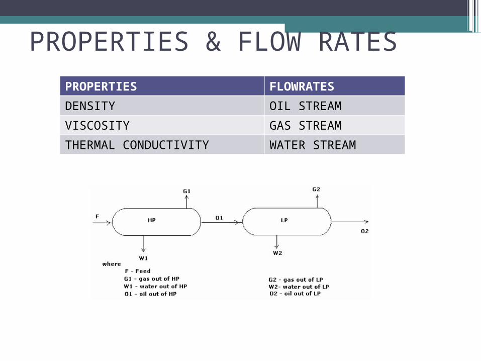
PROPERTIES & FLOW RATES
PROPERTIES FLOWRATES
DENSITY OIL STREAM
VISCOSITY GAS STREAM
THERMAL CONDUCTIVITY WATER STREAM

UNIT OPERATIONS 8 MINUTES
SeparatorsPipelinesPumpsValvesHeat ExchangersProcess controls

Separators
CV13
LT LIC
CV18
CV12
CV19
CV11CV10
PT
PIC
CV9
CV17CV16 PIC
CV15
PT
CV14
TT
TIC
TT
TIC
CV7
LT LIC
CV6CV5CV4
Gas treatment
plant
PIC
PT
LT LIC
PIC
PT
CV20
PT
PIC
Gas pipeline transportto export station
Liquid pipeline transportexport station
25 Km
20 Km
Slug CatcherCrude oil
HP separatorP = 20 barT = 40 C
LP separatorP = 10 barT = 45 C
Flare System
Steam in
Steam out
Steam in
Steam out
NRV
Pumping stationWater treatment
plant
Compressor station
Hydrocyclone
strainer
CV3
Well Head Manifold
CV1 CV2
Water disposal, 25 ppm
Productionof oil
75000 BPD(given)
App. Productionof gas,
41.4 MMcfd(calculated)
K7O – Group H131
PTPIC
LICLT
LIC
LT
Vessel
Level Controller
Pressure controller
Feed stream
Water stream
Oil stream
Gas stream
Heat exchanger
Flare system
CV8
Control valve
ESD valve, Powered valve
Pressure relief valve
Uni
form
flow
Slu
ggis
h flo
w
CV21
CV22
Non return valve

Design considerations

Design Inputs

Algorithm for Separation design using DSM
Droplet Settling Method
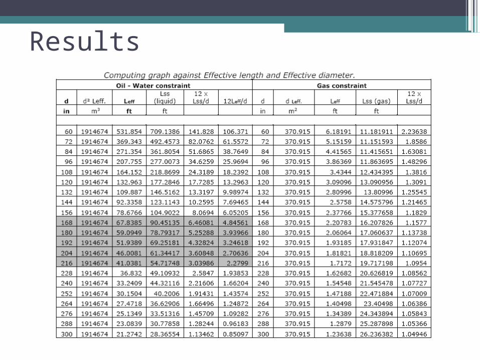
Results

Process piping & pumpingValvesHeat exchangers
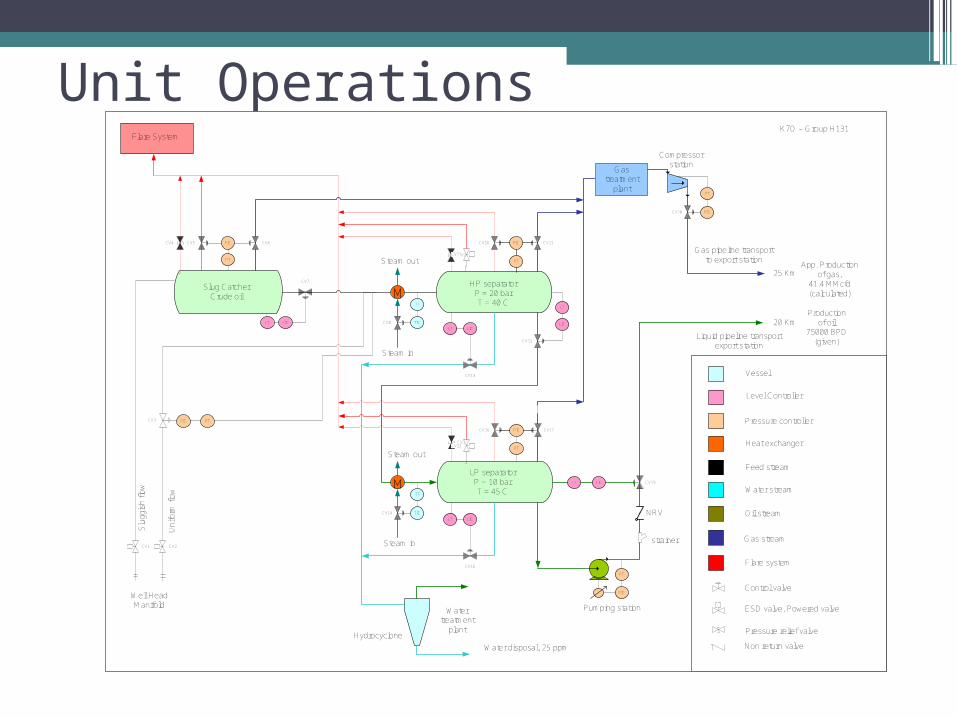
Unit Operations
CV13
LT LIC
CV18
CV12
CV19
CV11CV10
PT
PIC
CV9
CV17CV16 PIC
CV15
PT
CV14
TT
TIC
TT
TIC
CV7
LT LIC
CV6CV5CV4
Gas treatment
plant
PIC
PT
LT LIC
PIC
PT
CV20
PT
PIC
Gas pipeline transportto export station
Liquid pipeline transportexport station
25 Km
20 Km
Slug CatcherCrude oil
HP separatorP = 20 barT = 40 C
LP separatorP = 10 barT = 45 C
Flare System
Steam in
Steam out
Steam in
Steam out
NRV
Pumping stationWater treatment
plant
Compressor station
Hydrocyclone
strainer
CV3
Well Head Manifold
CV1 CV2
Water disposal, 25 ppm
Productionof oil
75000 BPD(given)
App. Productionof gas,
41.4 MMcfd(calculated)
K7O – Group H131
PTPIC
LICLT
LIC
LT
Vessel
Level Controller
Pressure controller
Feed stream
Water stream
Oil stream
Gas stream
Heat exchanger
Flare system
CV8
Control valve
ESD valve, Powered valve
Pressure relief valve
Uni
form
flow
Slu
ggis
h flo
w
CV21
CV22
Non return valve

Process piping and pumping

LiquidPipeline Design

GasPipeline Design

Pump Design

Valve Design

Heat ExchangerDesign

Heat ExchangerDesign

FLOW ASSURANCE
Ensure pumps run at Best efficiency point (BEP)

Flow Modeleling while ensuring proper Flow characteristics for Piping components like Pumps, valves, flowmeters etc.
Type of flow in wells
FLOW ASSURANCE

FLOW ASSURANCE
Valve selection for specific purpose
FO, FC Initial Half open Additional flow
accommodation for tuning valve +/- 10% to catch slugging

Other Major Considerations ForTopside Design
TO MEET CUSTOMER DEMANDS FOR GAS & OIL COMPOSITION (Thermodynamic PVT adjustments)
REDUCE F-F MINIMUM PIPING LENGTHS (Installing efficient Instruments that require least Upstream & Downstream piping lengths)

References
Separator – Ken Arnold & Maurice Stewart, Surface production operations Vol I, ISBN: 0-88415-821-7