surface issued vehicle jun2003 … j2522 台架制动性能等同于...sae technical standards board...
TRANSCRIPT

SAE Technical Standards Board Rules provide that: �This report is pubvoluntary, and its applicability and suitability for any particular use, incl
SAE reviews each technical report at least every five years at which tim
Copyright © 2003 Society of Automotive Engineers, Inc.All rights reserved. No part of this publication may be reproduced, storerecording, or otherwise, without the prior written permission of SAE.
TO PLACE A DOCUMENT ORDER: Tel: 8Tel: 7Fax: 7Email: c
SAE WEB ADDRESS: http://www.
SURFACE
VEHICLERECOMMENDEDPRACTICEI
lished by SAE to advance the state of technical and engineeruding any patent infringement arising therefrom, is the sole r
e it may be reaffirmed, revised, or cancelled. SAE invites yo
d in a retrieval system or transmitted, in any form or by any m
77-606-7323 (inside USA and Canada)24-776-4970 (outside USA)[email protected]
sae.org
J2522IJ
ing sciences. The use of tesponsibility of the user.�
ur written comments and
eans, electronic, mecha
SSUEDUN2003
ssued 2003-06
Dynamometer Global Brake Effectiveness
Foreword—The globalization trend in the automotive industry necessitates the proper definition of applicable testprocedures for assessment and comparison of different friction materials. These comparison tests should proveuseful as a common ground for the development, selection, and quality assurance of friction linings.
The AK Working Group, which represents European manufacturers of friction linings and passenger car brakes,has developed an “AK Master” Standard in recent years. The SAE Brake Dynamometer Test Code StandardsCommittee considers this standard useful in supporting the technological efforts intended to improve motor vehiclebraking systems overall performance and safety. Therefore this committee is making the AK Master standardavailable to the industry as an SAE Recommended Practice.
This document should be used in conjunction with other applicable standards or test procedures (SAE, FederalCodes or other specific testing programs) to fully assess a friction material’s adequacy for a certain application orvehicle platform.
1. Scope
1.1 This SAE Recommended Practice defines an Inertia Dynamometer Test procedure that assesses theeffectiveness behavior of a friction material with regard to pressure, temperature and speed for motor vehiclesfitted with hydraulic brake actuation.
1.2 The main purpose of SAE J2522 is to compare friction materials under the most equal conditions possible. Toaccount for the cooling behavior of different test stands, the fade sections are temperature-controlled.
2. References—There are no referenced publications specified herein.
3. Definitions—To facilitate the application of this document, the following terms and definitions should apply.
3.1 Friction Value for a Brake Apply—Arithmetic average of all individual friction values for a brake apply
3.2 Nominal Friction Value—Average friction value for all brake applies without fading series and withouttemperature series
3.3 Minimum Friction Value—Lowest arithmetical average of the individual friction values for the fade sectionsand temperature series
his report is entirely
suggestions.
nical, photocopying,
SAE J2522 Issued JUN2003
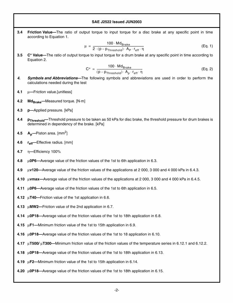
3.4 Friction Value—The ratio of output torque to input torque for a disc brake at any specific point in timeaccording to Equation 1.
(Eq. 1)
3.5 C* Value—The ratio of output torque to input torque for a drum brake at any specific point in time according toEquation 2.
(Eq. 2)
4. Symbols and Abbreviations—The following symbols and abbreviations are used in order to perform thecalculations needed during the test
4.1 µ—Friction value.[unitless]
4.2 MdBrake—Measured torque. [N·m]
4.3 p—Applied pressure. [kPa]
4.4 pThreshold—Threshold pressure to be taken as 50 kPa for disc brake, the threshold pressure for drum brakes isdetermined in dependency of the brake. [kPa]
4.5 Ap—Piston area. [mm2]
4.6 reff—Effective radius. [mm]
4.7 η—Efficiency 100%
4.8 µ0P6—Average value of the friction values of the 1st to 6th application in 6.3.
4.9 µv120—Average value of the friction values of the applications at 2 000, 3 000 and 4 000 kPa in 6.4.3.
4.10 µvmax—Average value of the friction values of the applications at 2 000, 3 000 and 4 000 kPa in 6.4.5.
4.11 µ0P6—Average value of the friction values of the 1st to 6th application in 6.5.
4.12 µT40—Friction value of the 1st application in 6.6.
4.13 µMW2—Friction value of the 2nd application in 6.7.
4.14 µ0P18—Average value of the friction values of the 1st to 18th application in 6.8.
4.15 µF1—Minimum friction value of the 1st to 15th application in 6.9.
4.16 µ0P18—Average value of the friction values of the 1st to 18 application in 6.10.
4.17 µT500/ µT300—Minimum friction value of the friction values of the temperature series in 6.12.1 and 6.12.2.
4.18 µ0P18—Average value of the friction values of the 1st to 18th application in 6.13.
4.19 µF2—Minimum friction value of the 1st to 15th application in 6.14.
4.20 µ0P18—Average value of the friction values of the 1st to 18th application in 6.15.
µ100 MdBrake⋅
2 p pThreshold–( ) AP reff η⋅ ⋅ ⋅ ⋅--------------------------------------------------------------------------------=
C∗ 100 MdBrake⋅p pThreshold–( ) Ap reff η⋅ ⋅ ⋅
------------------------------------------------------------------------=
-2-

SAE J2522 Issued JUN2003
5. Test Conditions
5.1 Inertia for the Front Axle—According to half of 75% of the gross vehicle weight if not otherwise specified.
5.2 Inertia for the Rear Axle—According to half of 25% of the gross vehicle weight if not otherwise specified.
5.3 Pressure Rise Rate—25 000 kPa/s ± 5 000 kPa/s.
5.4 Sampling Rate—Minimum 50 ms for pressure and torque.
5.5 Temperature Measurement—Position thermocouple at the friction path center radius 0.5 mm ± 0.1 mm deepin the disc outer face or drum contact face. Additional thermocouple(s) can be set in the friction material fortemperature recording purposes.
5.6 Cooling Air Conditions—For 6.9, 6.12.1, 6.12.2, and 6.14: air inlet 0%, air outlet 100%. For all other sectionscooling air speed should be 5 to 10 km/h.
5.7 Fade Sections—The fade sections are controlled by torque and temperature. The braking torque isdetermined by the vehicle weight, the braking force distribution, the rolling radius, and the specifieddeceleration. (See Table 1.)
The starting temperatures are calculated by Equation 3.
(Eq. 3)
If initial temperatures cannot be reached in 6.12.1 and 6.12.2, then perform 80 km/h drags at a braking torquecorresponding to 0.2 g maximum deceleration for 20 s drag time. However, only the temperatures described inthe program are to be collected for test report purposes. If initial temperatures are not reached in 6.9 and 6.14,the temperature levels can be the final temperature of the previous stop. Warmup stops should not beperformed for these sections.
5.8 Brake disc material should be made of gray cast iron.
5.9 All specified values are recommended and can be adjusted according to the brake being tested.
TABLE 1—INITIAL TEMPERATURES FOR FADE STOPS
Stop
Initial temperature for disc brake
°C
Initial temperature for drum brake
°C
1 100 100
2 215 151
3 283 181
4 330 202
5 367 219
6 398 232
7 423 244
8 446 254
9 465 262
10 483 270
11 498 277
12 513 284
13 526 289
14 539 295
15 550 300
TAN TA15 TA1–( ) In 15( )⁄[ ] In N( ) TA1+×=
-3-

SAE J2522 Issued JUN2003
6. Test Procedure
6.1 Green µ Characteristic—30 snubs 80 to 30 km/h at 3 000 kPa. See Table 2.
6.2 Burnish—192 snubs 80 to 30 km/h at varying pressures. (Optional 2 cycle “64 snubs”.) See Table 3.
TABLE 2—GREEN µ CHARACTERISTIC SECTION
Parameter Front axleRear axle
Disc brakeRear axle
Drum brake
Number of snubs per cycle 30 30 30
Brake speed (km/h) 80 80 80
Release speed (km/h) 30 30 30
Pressure (kPa) 3 000 3 000 3 000
Initial brake temperature (°C) ≤100 ≤100 ≤80
Final brake temperature (°C) Open Open Open
Number of cycles 1 1 1
TABLE 3—BURNISH SECTION
Parameter Front axleRear axle
Disc brakeRear axle
Drum brake
Number of snubs per cycle 32 32 32
Brake speed (km/h) 80 80 80
Release speed (km/h) 30 30 30
Initial brake temperature (°C) ≤100 ≤100 ≤80
Final brake temperature (°C) Open Open Open
Pressure snub 1 (kPa) 1 500 1 500 1 500
Pressure snub 2 (kPa) 3 000 3 000 3 000
Pressure snub 3 (kPa) 1 500 1 500 1 500
Pressure snub 4 (kPa) 1 800 1 800 1 800
Pressure snub 5 (kPa) 2 200 2 200 2 200
Pressure snub 6 (kPa) 3 800 3 800 3 800
Pressure snub 7 (kPa) 1 500 1 500 1 500
Pressure snub 8 (kPa) 2 600 2 600 2 600
Pressure snub 9 (kPa) 1 800 1 800 1 800
Pressure snub 10 (kPa) 3 400 3 400 3 400
Pressure snub 11 (kPa) 1 500 1 500 1 500
Pressure snub 12 (kPa) 2 600 2 600 2 600
Pressure snub 13 (kPa) 1 500 1 500 1 500
Pressure snub 14 (kPa) 2 200 2 200 2 200
Pressure snub 15 (kPa) 3 000 3 000 3 000
Pressure snub 16 (kPa) 4 600 4 600 4 600
Pressure snub 17 (kPa) 2 600 2 600 2 600
Pressure snub 18 (kPa) 5 100 5 100 5 100
Pressure snub 19 (kPa) 2 200 2 200 2 200
Pressure snub 20 (kPa) 1 800 1 800 1 800
Pressure snub 21 (kPa) 4 200 4 200 4 200
Pressure snub 22 (kPa) 1 500 1 500 1 500
Pressure snub 23 (kPa) 1 800 1 800 1 800
Pressure snub 24 (kPa) 4 600 4 600 4 600
-4-

SAE J2522 Issued JUN2003
6.3 Characteristic Value 1—6 snubs 80 to 30 km/h at 3 000 kPa. See Table 4.
6.4 Speed/Pressure Sensitivity Sections—Pressure sensitivity at various brake and release speeds.
6.4.1 SPEED/PRESSURE SENSITIVITY 40 km/h—8 stops 40 to 5 km/h at increasing pressures. See Table 5.
Pressure snub 25 (kPa) 2 600 2 600 2 600
Pressure snub 26 (kPa) 1 500 1 500 1 500
Pressure snub 27 (kPa) 3 400 3 400 3 400
Pressure snub 28 (kPa) 2 200 2 200 2 200
Pressure snub 29 (kPa) 1 800 1 800 1 800
Pressure snub 30 (kPa) 3 000 3 000 3 000
Pressure snub 31 (kPa) 1 800 1 800 1 800
Pressure snub 32 (kPa) 3 800 3 800 3 800
Number of cycles 6 6 6
TABLE 4—CHARACTERISTIC VALUE 1 SECTION
Parameter Front axleRear axle
Disc brakeRear axle
Drum brake
Number of stops per cycle 6 6 6
Brake speed (km/h) 80 80 80
Release speed (km/h) 30 30 30
Pressure (kPa) 3 000 3 000 3 000
Initial brake temperature (°C) ≤100 ≤100 ≤80
Final brake temperature (°C) Open Open Open
Number of cycles 1 1 1
TABLE 5—SPEED/PRESSURE SENSITIVITY 40 km/h SECTION
Parameter Front axleRear axle
Disc brakeRear axle
Drum brake
Number of stops per cycle 8 8 7
Brake speed (km/h) 40 40 40
Release speed (km/h) ≤5 ≤5 ≤5
Initial brake temperature (°C) ≤100 ≤100 ≤80
Final brake temperature (°C) Open Open Open
Pressure stop 1 (kPa) 1 000 1 000 2 000
Pressure stop 2 (kPa) 2 000 2 000 3 000
Pressure stop 3 (kPa) 3 000 3 000 4 000
Pressure stop 4 (kPa) 4 000 4 000 5 000
Pressure stop 5 (kPa) 5 000 5 000 6 000
Pressure stop 6 (kPa) 6 000 6 000 7 000
Pressure stop 7 (kPa) 7 000 7 000 8 000
Pressure stop 8 (kPa) 8 000 8 000 —
Number of cycles 1 1 1
TABLE 3—BURNISH SECTION (CONTINUED)
Parameter Front axleRear axle
Disc brakeRear axle
Drum brake
-5-

SAE J2522 Issued JUN2003
6.4.2 SPEED/PRESSURE SENSITIVITY 80 km/h—8 snubs 80 to 40 km/h at increasing pressures. See Table 6.
6.4.3 SPEED/PRESSURE SENSITIVITY 120 km/h—8 snubs 120 to 80 km/h at increasing pressures. See Table 7.
TABLE 6—SPEED/PRESSURE SENSITIVITY 80 km/h SECTION
Parameter Front axleRear axle
Disc brakeRear axle
Drum brake
Number of snubs per cycle 8 8 7
Brake speed (km/h) 80 80 80
Release speed (km/h) 40 40 40
Initial brake temperature (°C) ≤100 ≤100 ≤80
Final brake temperature (°C) Open Open Open
Pressure snub 1 (kPa) 1 000 1 000 2 000
Pressure snub 2 (kPa) 2 000 2 000 3 000
Pressure snub 3 (kPa) 3 000 3 000 4 000
Pressure snub 4 (kPa) 4 000 4 000 5 000
Pressure snub 5 (kPa) 5 000 5 000 6 000
Pressure snub 6 (kPa) 6 000 6 000 7 000
Pressure snub 7 (kPa) 7 000 7 000 8 000
Pressure snub 8 (kPa) 8 000 8 000 —
Number of cycles 1 1 1
TABLE 7—SPEED/PRESSURE SENSITIVITY 120 km/h SECTION
Parameter Front axleRear axle
Disc brakeRear axle
Drum brake
Number of snubs per cycle 8 8 7
Brake speed (km/h) 120 120 120
Release speed (km/h) 80 80 80
Initial brake temperature (°C) ≤100 ≤100 ≤80
Final brake temperature (°C) Open Open Open
Pressure snub 1 (kPa) 1 000 1 000 2 000
Pressure snub 2 (kPa) 2 000 2 000 3 000
Pressure snub 3 (kPa) 3 000 3 000 4 000
Pressure snub 4 (kPa) 4 000 4 000 5 000
Pressure snub 5 (kPa) 5 000 5 000 6 000
Pressure snub 6 (kPa) 6 000 6 000 7 000
Pressure snub 7 (kPa) 7 000 7 000 8 000
Pressure snub 8 (kPa) 8 000 8 000 —
Number of cycles 1 1 1
-6-

SAE J2522 Issued JUN2003
6.4.4 SPEED/PRESSURE SENSITIVTY 160 km/h—8 snubs 160 to 130 km/h at increasing pressures. See Table 8.
6.4.5 SPEED/PRESSURE SENSITIVITY 200 km/h—8 snubs 200 to 170 km/h at increasing pressures. If vehiclemaximum speed below 200 km/h use brake speed equal to vehicle top speed and release speed of 30 km/hbelow vehicle top speed. See Table 9.
TABLE 8—SPEED/PRESSURE SENSITIVITY 160 km/h SECTION
Parameter Front axleRear axle
Disc brakeRear axle
Drum brake
Number of snubs per cycle 8 8 7
Brake speed (km/h) 160 160 160
Release speed (km/h) 130 130 130
Initial brake temperature (°C) ≤100 ≤100 ≤ 80
Final brake temperature (°C) Open Open Open
Pressure snub 1 (kPa) 1 000 1 000 2 000
Pressure snub 2 (kPa) 2 000 2 000 3 000
Pressure snub 3 (kPa) 3 000 3 000 4 000
Pressure snub 4 (kPa) 4 000 4 000 5 000
Pressure snub 5 (kPa) 5 000 5 000 6 000
Pressure snub 6 (kPa) 6 000 6 000 7 000
Pressure snub 7 (kPa) 7 000 7 000 8 000
Pressure snub 8 (kPa) 8 000 8 000 —
Number of cycles 1 1 1
TABLE 9—SPEED/PRESSURE SENSITIVITY 200 km/h SECTION
Parameter Front axleRear axle
Disc brakeRear axle
Drum brake
Number of snubs per cycle 8 8 7
Brake speed (km/h) 200 200 200
Release speed (km/h) 170 170 170
Initial brake temperature (°C) ≤100 ≤100 ≤80
Final brake temperature (°C) Open Open Open
Pressure snub 1 (kPa) 1 000 1 000 2 000
Pressure snub 2 (kPa) 2 000 2 000 3 000
Pressure snub 3 (kPa) 3 000 3 000 4 000
Pressure snub 4 (kPa) 4 000 4 000 5 000
Pressure snub 5 (kPa) 5 000 5 000 6 000
Pressure snub 6 (kPa) 6 000 6 000 7 000
Pressure snub 7 (kPa) 7 000 7 000 8 000
Pressure snub 8 (kPa) 8 000 8 000 —
Number of cycles 1 1 1
-7-

SAE J2522 Issued JUN2003
6.5 Characteristic Value 2—6 snubs 80 to 30 km/h at 3 000 kPa. See Table 10.
6.6 Cold Application—1 stop 40 to 5 km/h at 3 000 kPa. See Table 11.
6.7 Motorway Applications—1 stop and 1 snub at 0.6 g. See Table 12.
TABLE 10—CHARACTERISTIC VALUE 2 SECTION
Parameter Front axleRear axle
Disc brakeRear axle
Drum brake
Number of stops per cycle 6 6 6
Brake speed (km/h) 80 80 80
Release speed (km/h) 30 30 30
Pressure (kPa) 3 000 3 000 3 000
Initial brake temperature (°C) ≤100 ≤100 ≤80
Final brake temperature (°C) Open Open Open
Number of cycles 1 1 1
TABLE 11—COLD APPLICATION SECTION
Parameter Front axleRear axle
Disc brakeRear axle
Drum brake
Number of stops per cycle 1 1 1
Brake speed (km/h) 40 40 40
Release speed (km/h) ≤5 ≤5 ≤5
Pressure (kPa) 3 000 3 000 3 000
Initial brake temperature (°C) ≤40 ≤40 ≤40
Final brake temperature (°C) Open Open Open
Number of cycles 1 1 1
TABLE 12—MOTORWAY APPLICATIONS SECTIONS
Parameter Front axleRear axle
Disc brakeRear axle
Drum brake
Number of stops per cycle 2 2 2
Brake speed for stop 1 (km/h) 100 100 100
Brake speed for snub 2 (km/h) 90% of Vmax 90% of Vmax 90% of Vmax
Release speed for stop 1 (km/h) ≤5 ≤5 ≤5
Release speed for snub 2 (km/h) 50% of Vmax 50% of Vmax 50% of Vmax
Deceleration level (g) 0.6 0.6 0.6
Initial brake temperature (°C) ≤50 ≤50 ≤50
Final brake temperature (°C) Open Open Open
Number of cycles 1 1 1
-8-

SAE J2522 Issued JUN2003
6.8 Characteristic Value 3—18 snubs 80 to 30 km/h at 3 000 kPa. See Table 13.
6.9 Fade 1—15 stops 100 to 5 km/h at 0.4 g and increasing initial temperatures. See Table 14.
TABLE 13— CHARACTERISTIC VALUE 3 SECTION
Parameter Front axleRear axle
Disc brakeRear axle
Drum brake
Number of stops per cycle 18 18 18
Brake speed (km/h) 80 80 80
Release speed (km/h) 30 30 30
Pressure (kPa) 3 000 3 000 3 000
Initial brake temperature (°C) ≤100 ≤100 ≤80
Final brake temperature (°C) Open Open Open
Number of cycles 1 1 1
TABLE 14—FADE 1 SECTION
Parameter Front axleRear axle
Disc brakeRear axle
Drum brake
Number of stops per cycle 15 15 15
Brake speed (km/h) 100 100 100
Release speed (km/h) ≤5 ≤5 ≤5
Deceleration level (g) 0.4 0.4 0.4
Maximum pressure (kPa) 16 000 16 000 10 000
Initial temperature 1 (°C) ≤100 ≤100 ≤100
Initial temperature 2 (°C) ≤215 ≤215 ≤151
Initial temperature 3 (°C) ≤283 ≤283 ≤181
Initial temperature 4 (°C) ≤330 ≤330 ≤202
Initial temperature 5 (°C) ≤367 ≤367 ≤219
Initial temperature 6 (°C) ≤398 ≤398 ≤232
Initial temperature 7 (°C) ≤423 ≤423 ≤244
Initial temperature 8 (°C) ≤446 ≤446 ≤254
Initial temperature 9 (°C) ≤465 ≤465 ≤262
Initial temperature 10 (°C) ≤483 ≤483 ≤270
Initial temperature 11 (°C) ≤498 ≤498 ≤277
Initial temperature 12 (°C) ≤513 ≤513 ≤284
Initial temperature 13 (°C) ≤526 ≤526 ≤289
Initial temperature 14 (°C) ≤539 ≤539 ≤295
Initial temperature 15 (°C) ≤550 ≤550 ≤300
Final brake temperature (°C) Open Open Open
Number of cycles 1 1 1
-9-

SAE J2522 Issued JUN2003
6.10 Recovery 1—18 snubs 80 to 30 km/h at 3 000 kPa. See Table 15.
6.11 Temperature/Pressure Sensitivity 100 °C/80 °C—8 snubs 80 to 30 km/h at increasing pressure. See Table16.
TABLE 15—RECOVERY 1 SECTION
Parameter Front axleRear axle
Disc brakeRear axle
Drum brake
Number of stops per cycle 18 18 18
Brake speed (km/h) 80 80 80
Release speed (km/h) 30 30 30
Pressure (kPa) 3 000 3 000 3 000
Initial brake temperature (°C) ≤100 ≤100 ≤80
Final brake temperature (°C) Open Open Open
Number of cycles 1 1 1
TABLE 16—TEMPERATURE/PRESSURE SENSITIVITY 100 °C/80 °C SECTION
Parameter Front axleRear axle
Disc brakeRear axle
Drum brake
Number of snubs per cycle 8 8 7
Brake speed (km/h) 80 80 80
Release speed (km/h) 30 30 30
Initial brake temperature (°C) ≤100 ≤100 ≤80
Final brake temperature (°C) Open Open Open
Pressure snub 1 (kPa) 1 000 1 000 2 000
Pressure snub 2 (kPa) 2 000 2 000 3 000
Pressure snub 3 (kPa) 3 000 3 000 4 000
Pressure snub 4 (kPa) 4 000 4 000 5 000
Pressure snub 5 (kPa) 5 000 5 000 6 000
Pressure snub 6 (kPa) 6 000 6 000 7 000
Pressure snub 7 (kPa) 7 000 7 000 8 000
Pressure snub 8 (kPa) 8 000 8 000 —
Number of cycles 1 1 1
-10-

SAE J2522 Issued JUN2003
6.12 Temperature/Pressure Sensitivity 500 °C/300 °C sections—Temperature sensitivity at constant pressureand pressure sensitivity at high temperature.
6.12.1 INCREASING TEMPERATURE 500 °C/300 °C—9 snubs 80 to 30 km/h at increasing temperature. See Table 17.
6.12.2 PRESSURE LINE 500 °C/300 °C—8 snubs 80 to 30 km/h at increasing pressure. See Table 18.
TABLE 17—INCREASING TEMPERATURE 500 °C/300 °C SECTION
Parameter Front axleRear axle
Disc brakeRear axle
Drum brake
Number of snubs per cycle 9 9 5
Brake speed (km/h) 80 80 80
Release speed (km/h) 30 30 30
Pressure (kPa) 3 000 3 000 3 000
Initial temperature 1 (°C) ≤100 ≤100 ≤100
Initial temperature 2 (°C) ≤150 ≤150 ≤150
Initial temperature 3 (°C) ≤200 ≤200 ≤200
Initial temperature 4 (°C) ≤250 ≤250 ≤250
Initial temperature 5 (°C) ≤300 ≤300 ≤300
Initial temperature 6 (°C) ≤350 ≤350 —
Initial temperature 7 (°C) ≤400 ≤400 —
Initial temperature 8 (°C) ≤450 ≤450 —
Initial temperature 9 (°C) ≤500 ≤500 —
Final brake temperature (°C) Open Open Open
Number of cycles 1 1 1
TABLE 18—PRESSURE LINE 500 °C/300 °C SECTION
Parameter Front axleRear axle
Disc brakeRear axle
Drum brake
Number of snubs per cycle 8 8 7
Brake speed (km/h) 80 80 80
Release speed (km/h) 30 30 30
Initial brake temperature (°C) ≤500 ≤500 ≤300
Final brake temperature (°C) Open Open Open
Pressure snub 1 (kPa) 1 000 1 000 2 000
Pressure snub 2 (kPa) 2 000 2 000 3 000
Pressure snub 3 (kPa) 3 000 3 000 4 000
Pressure snub 4 (kPa) 4 000 4 000 5 000
Pressure snub 5 (kPa) 5 000 5 000 6 000
Pressure snub 6 (kPa) 6 000 6 000 7 000
Pressure snub 7 (kPa) 7 000 7 000 8 000
Pressure snub 8 (kPa) 8 000 8 000 -
Number of cycles 1 1 1
-11-

SAE J2522 Issued JUN2003
6.13 Recovery 2—18 snubs 80 to 30 km/h at 3 000 kPa. See Table 19.
6.14 Fade 2—15 stops 100 to 5 km/h at 0.4 g and increasing initial temperatures. See Table 20.
TABLE 19—RECOVERY 2 SECTION
Parameter Front axleRear axle
Disc brakeRear axle
Drum brake
Number of stops per cycle 18 18 18
Brake speed (km/h) 80 80 80
Release speed (km/h) 30 30 30
Pressure (kPa) 3 000 3 000 3 000
Initial brake temperature (°C) ≤100 ≤100 ≤80
Final brake temperature (°C) Open Open Open
Number of cycles 1 1 1
TABLE 20—FADE 2 SECTION
Parameter Front axleRear axle
Disc brakeRear axle
Drum brake
Number of stops per cycle 15 15 15
Brake speed (km/h) 100 100 100
Release speed (km/h) ≤5 ≤5 ≤5
Deceleration level (g) 0.4 0.4 0.4
Maximum pressure (kPa) 16 000 16 000 10 000
Initial temperature 1 (°C) ≤100 ≤100 ≤100
Initial temperature 2 (°C) ≤215 ≤215 ≤151
Initial temperature 3 (°C) ≤283 ≤283 ≤181
Initial temperature 4 (°C) ≤330 ≤330 ≤202
Initial temperature 5 (°C) ≤367 ≤367 ≤219
Initial temperature 6 (°C) ≤398 ≤398 ≤232
Initial temperature 7 (°C) ≤423 ≤423 ≤244
Initial temperature 8 (°C) ≤446 ≤446 ≤254
Initial temperature 9 (°C) ≤465 ≤465 ≤262
Initial temperature 10 (°C) ≤483 ≤483 ≤270
Initial temperature 11 (°C) ≤498 ≤498 ≤277
Initial temperature 12 (°C) ≤513 ≤513 ≤284
Initial temperature 13 (°C) ≤526 ≤526 ≤289
Initial temperature 14 (°C) ≤539 ≤539 ≤295
Initial temperature 15 (°C) ≤550 ≤550 ≤300
Final brake temperature (°C) Open Open Open
Number of cycles 1 1 1
-12-
SAE J2522 Issued JUN2003
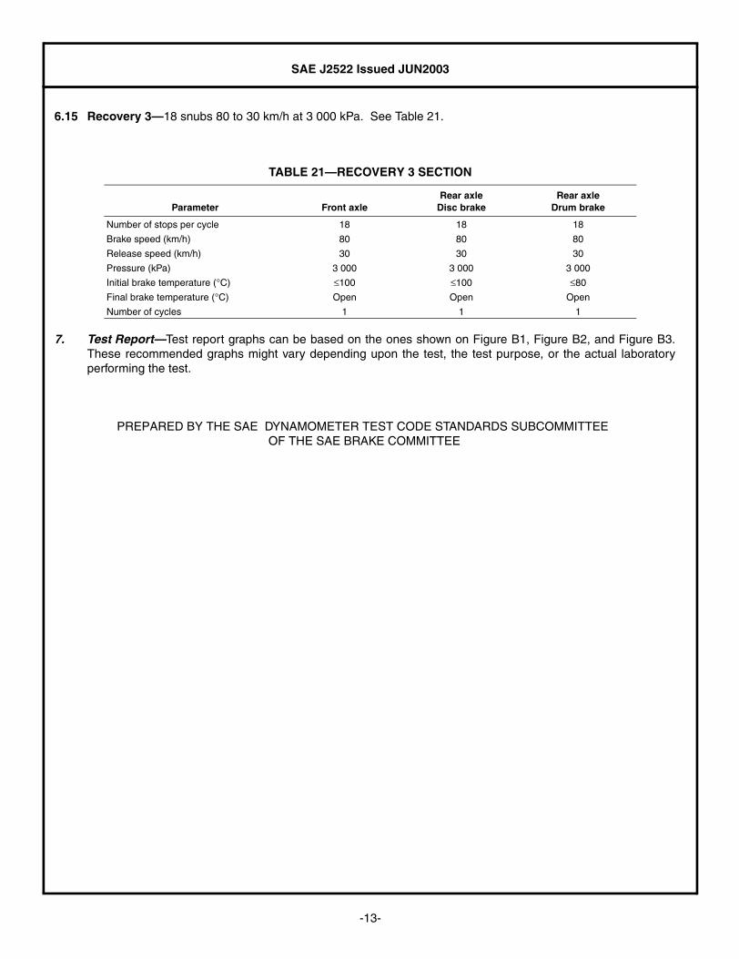
6.15 Recovery 3—18 snubs 80 to 30 km/h at 3 000 kPa. See Table 21.
7. Test Report—Test report graphs can be based on the ones shown on Figure B1, Figure B2, and Figure B3.These recommended graphs might vary depending upon the test, the test purpose, or the actual laboratoryperforming the test.
PREPARED BY THE SAE DYNAMOMETER TEST CODE STANDARDS SUBCOMMITTEE OF THE SAE BRAKE COMMITTEE
TABLE 21—RECOVERY 3 SECTION
Parameter Front axleRear axle
Disc brakeRear axle
Drum brake
Number of stops per cycle 18 18 18
Brake speed (km/h) 80 80 80
Release speed (km/h) 30 30 30
Pressure (kPa) 3 000 3 000 3 000
Initial brake temperature (°C) ≤100 ≤100 ≤80
Final brake temperature (°C) Open Open Open
Number of cycles 1 1 1
-13-

SAE J2522 Issued JUN2003
APPENDIX A
VEHICLE AND TEST PARAMETERS REQUIRED TO RUN A SAE J2522 BASED TEST
A.1 Preface—The recommended parameters shown are necessary prior to running an SAE J2522 test (see TableA1)
TABLE A1—VEHICLE AND TEST PARAMETERS
Parameter Symbol Units Value
Vehicle description —
Axle to test —
Brake description —
Disc brake (Diameter x Thickness) — [mm] x
Drum brake (Diameter x Lining thickness) — [mm] x
Effective radius reff [mm]
Piston diameter — [mm]
Piston area Ap [mm2]
Threshold pressure pThreshold [kPa]
Rolling radius r [mm]
Gross vehicle weight GVW [kg]
Test inertia I [kg m2]
Brake torque at 1.0 g deceleration Md [N·m]
Efficiency ηH [%]
Vehicle maximum rated speed Vmax [km/h]
-14-

SAE J2522 Issued JUN2003
APPENDIX B
FIGURE B1—SAMPLE TEST REPORT PLOT PAGE SAE J2522
-15-

SAE J2522 Issued JUN2003
FIGURE B2—SAMPLE TEST REPORT PLOT PAGE SAE J2522
-16-

SAE J2522 Issued JUN2003
FIGURE B3—SAMPLE TEST REPORT PLOT PAGE SAE J2522
-17-

SAE J2522 Issued JUN2003
Rationale—SAE J2522 is intended as an effectiveness evaluation to assist platform designers, systemsengineers, and component suppliers assessing specific friction material characteristics when subjectedto series of different pressures, speeds, and temperatures.
Different pressures, speeds, and temperature combinations used during the test give a betterunderstanding of the main factors that might affect a brake material’s actual performance subjected tovehicle conditions for extended time periods.
Proper use of this recommended practice has proved useful on the European market for several frictionmaterial manufacturers and designers. SAE J2522 is based on the structure, reasoning, and sectiondefinition of the latest available AK Master test procedure version when generating this document.
Systematic use of this recommended practice during the development and later quality assuranceprograms could be very useful for application or platform engineers. This standard complements differenttest that assess mechanical, chemical, noise, wear, rotor or drum kindness, and vehicle testing. Generalquality assurance initiatives like ISO 9000, WS 9000, VDI, DIN, etc. could be part of an all-encompassing brake design engineering program.
Also noteworthy, use of this recommended practice would minimize confusion when comparing andperforming several differing test code versions defined as an AK Master or Global Specification.
There are no minimum specifications or requirements for any section or stop on the test. Performancelevels and technical requirements depend more upon the specific application for which the brake lining isintended and upon additional criteria that go beyond the reach of this recommended practice. Eachcustomer and vendor should properly define specific requirements as part of their business relationship.
Relationship of SAE Standard to ISO Standard—Not applicable.
Application—This SAE Recommended Practice defines an Inertia Dynamometer Test procedure thatassesses the effectiveness behavior of a friction material with regard to pressure, temperature andspeed for motor vehicles fitted with hydraulic brake actuation.
The main purpose of SAE J2522 is to compare friction materials under the most equal conditionspossible. To account for the cooling behavior of different test stands, the fade sections are temperature-controlled.
Reference Section—There are no referenced publications specified herein.
Developed by the SAE Dynamometer Test Code Standards Subcommittee
Sponsored by the SAE Brake Committee