surface & coatings technology -...
TRANSCRIPT

Surface & Coatings Technology 228 (2013) 275–281
Contents lists available at SciVerse ScienceDirect
Surface & Coatings Technology
j ourna l homepage: www.e lsev ie r .com/ locate /sur fcoat
Microstructure, mechanical and tribological behaviors of MoS2-Ti composite coatingsdeposited by a hybrid HIPIMS method
Xiaopeng Qin a, Peiling Ke a,⁎, Aiying Wang a,⁎, Kwang Ho Kim b
a Ningbo Key Laboratory of Marine Protection Materials, Ningbo Institute of Materials Technology and Engineering, Chinese Academy of Sciences, Ningbo 315201, Chinab National Core Research Center for Hybrid Materials Solution, Pusan National University, Pusan 609735, Korea
⁎ Corresponding authors. Tel.: +86 574 86685036.E-mail addresses: [email protected] (P. Ke), aywang
0257-8972/$ – see front matter © 2013 Elsevier B.V. Allhttp://dx.doi.org/10.1016/j.surfcoat.2013.04.040
a b s t r a c t
a r t i c l e i n f oArticle history:Received 21 November 2012Accepted in revised form 17 April 2013Available online 24 April 2013
Keywords:Hybrid high power impulse magnetronsputteringMoS2-Ti composite coatingsMicrostructureTribology
The MoS2-Ti composite coatings were deposited by a hybrid high power impulse magnetron sputtering(HIPIMS) source of Ti combined with a direct current magnetron sputtering (DC-MS) source of MoS2. Thecomposition, microstructure, mechanical and tribological behaviors of the MoS2-Ti composite coatingswere investigated using the various analytical techniques (XPS, SEM, XRD, TEM, nano-indentation, scratchand ball-on-disk test). The results showed that doping Ti using HIPIMS technique enabled MoS2 coatings togrow in the form of a dense amorphous structure. The crystallization degree of the MoS2-Ti compositecoatings decreased with the increase of doped titanium content. Ti reacting with O to form titanium oxidesin the surface inhibited the oxidation of MoS2. The hardness and adhesion of the composite coatings reachedits maximumwithin a certain range of Ti content. Doped Ti improved the tribological properties of pure MoS2coatings in the atmospheric environment. The coefficient of friction (COF) decreased with the increase ofTi content. The lowest average COF at 0.04 and the wear rate at 10−7 mm3 N−1 m−1 were achieved at theoptimum of Ti content at 13.5 at.%. The improved tribological property was discussed in terms of theobtained higher hardness and better adhesion of the composite coatings combined with inhibition of MoS2oxidation.
© 2013 Elsevier B.V. All rights reserved.
1. Introduction
Sputtered MoS2 coating as an excellent solid lubricant has beenwidely used in the vacuum and space field such as the spacecraftmotion components and rolling bearings due to the high wearresistance durability and very low coefficient of friction [1,2]. However,pure sputtered MoS2 coating generally exhibits the loose structure,low hardness and high chemical activity to oxygen, resulting in thedeteriorated wear durability and the corrosion resistance [3]. Recently,doping small amount of metal or ceramic elements into MoS2coatings has been attempted to improve the lubricant and corrosionperformance of MoS2 coating [4–9]. It is found that doping themetals such as Al, Au, W, etc., in the MoS2 coatings by magnetronco-sputtering showed good friction stability in ambient air withlong-lasting wear durability [5–7]. In addition, introduction of TiN orTiB2 was also developed to modify the tribological properties of pureMoS2 coatings [10,11]. Specially, note that the addition of Ti into theMoS2 coating in recent years has drawn much attention because ofthe significant improvement of the oxidation resistance and tribologicalperformance dependent on the humidity in ambient air [12].
Usually, the employed doping metal components are acquiredusing a conventional direct current magnetron sputtering. However,
@nimte.ac.cn (A. Wang).
rights reserved.
the ionization degree of the plasma particles is relatively low, leadingto poor coating adhesion to substrate and densification deteriorationof coating structure [12,13]. As a consequence, the coating wassuffered from the structural degradation due to oxidation causinglubrication failure.
A magnetron sputtering method, which is called high powerimpulse magnetron sputtering (HIPIMS), has been developed since1990s, where high density plasma with electron densities about 2–3orders of magnitude larger than those obtained in conventional mag-netron sputtering and high sputtering particle ionization rate may beachieved [14–16]. A great deal of research has been conducted tostudy the effects of this technique on properties of the depositedcoating [17,18], such as densification, changes in structure andproperties of coating [19]. From a durability and reliability prospec-tive of MoS2 coatings in multi-environmental application, if theHIPIMS technique as a metal plasma source is combined with the de-position of MoS2 coatings, rather than the general used DC-MS andcathodic arc plating hybrid method, one can expect that the structureand properties of coating could be well tailored according to thedemanded applications [19].
HIPIMS requires higher excitation voltage, then the ionizedparticles may be draw back by target itself because of the highnegative voltage of the target surface, causing low film depositionrate. To solve the problem, a modified HIPIMS power supply coupleda DC unit with the high power pulse unit has been employed in the

Fig. 1. Schematic diagrams: (a) the hybrid HIPIMS deposition system of MoS2-Ticomposite coatings and (b) a parallel connection operation mode of HIPIMS powersupply.
276 X. Qin et al. / Surface & Coatings Technology 228 (2013) 275–281
present work. On the one hand, a high deposition rate can beobtained by the coupled DC unit; on the other hand, a DC unitcould optimize pulse glowing and plasma stabilization throughpre-ionization [11,20]. During the deposition, the power supply wasable to deliver both pulses and DC, where a DC unit was also usedto easily control the doped Ti content in the coatings. In addition, ahigh power impulse could produce plasmas with highly ionizedmetallic species with high ion energy. In the preliminary researchwork, we obtained the optimized parameters of high power pulsepart, pressure and bias voltage, which were fixed in the process andwere beneficial to enhanced mechanical and tribological behaviorsof MoS2-Ti composite coatings.
MoS2-Ti composite coatingswith different Ti contentswere thereafterdeposited by the co-sputtering of the hybrid HIPIMS system for Ti and aDC magnetron sputtering unit for MoS2. Different Ti doping contents inthe coatings were obtained by varying the target current. The influenceof Ti contents on microstructure, mechanical properties and tribologicalbehaviors in atmospheric environment was investigated.
2. Experimental details
Hybrid high power impulse magnetron sputtering system wasemployed to deposit the pure MoS2 and MoS2-Ti composite coatingsonto mirror-finished high speed steel (HSS) discs and siliconP-(100) substrates. The system was combined with a Ti targetconnecting to high power impulse power supply with a MoS2 target
Table 1Process parameters for MoS2-Ti composite coatings deposition.
Deposition parameters Ti interlayer MoS2-Ti composite coatings
Ar (sccm) 40 50Bias voltage (V) −100 −300Pulse width (μs) 100 100Pulse frequency (Hz) 100 100Ti target pulse voltage (V) 500 500Ti target direct current (A) 2.0 0.5, 0.8, 1.0, 1.5, 2.0
connecting to DC power supply. The distance between the targetand the substrate was 11 cm. The schematic diagram of the systemis shown in Fig. 1(a), and the parallel connection of HIPIMS powersupply is shown in Fig. 1(b), in which the pulsed power by theconstant voltage mode is adjusted to achieve the high impulsepower and the DC power by the constant current mode was regulatedto obtain the different content of doped Ti. Before loading into thevacuum chamber, all the substrates were ultrasonically cleaned inacetone and ethanol for 15 min, respectively, and then dried in air.Thereafter, the cleaned substrates were mounted on the rotatedsubstrate holder in the chamber. Prior to deposition, the chamberwas pumped down to less than 3 × 10⁻⁵ Torr, and the substrateswere cleaned in the argon plasma for 30 minutes. The Ti interlayer(~100 nm) was first constructed to enhance the coating adhesion tothe substrate. During the deposition of top MoS2-Ti compositecoatings, DC magnetron sputtering current applied onto the MoS2target was fixed at 1.0 A, and HIPIMS power with various currents(0.5, 0.8, 1.0, 1.5 and 2.0 A) was supplied to the Ti target magnetronsputtering unit to control the doped Ti content in the coatings. Theprocess parameters are shown in Table 1. A negative pulsed directcurrent bias, with a frequency of 350 kHz and reverse time of 1.1 μs,was applied to the substrates during the coating deposition.
The thicknesses of the deposited coatings were measured by asurface profilometer (KLA-Tencor, Alpha-Step IQ) through a stepbetween the coatings and the Si wafers covered with a shadowmask. Surface morphology of the coatings was studied by a fieldemission scanning electron microscope (S4800, Hitachi). The compo-sition and chemical bonds of the deposited coatings was analyzed byX-ray photoelectron spectroscopy (XPS, Axis ultraDLD) with Al(mono) Kα irradiation at the pass energy of 160 eV. Before takingthe measurement, an Ar + ion beam with the energy of 3 keV wasused to etch the sample surface for 5 min to remove contaminants.X-ray diffraction (XRD) measurements were performed by AXS D8Advance diffractometer (Bruker). High-resolution transmission elec-tron microscopy (TEM) of the coatings was carried out on a TecnaiF20 electron microscope (FEI), which was operated at 200 KeVwith a point-to-point resolution of 0.24 nm. The specimens for TEManalysis, with thicknesses of about 50 nm, were deposited directlyon freshly cleaved single-crystal NaCl wafers and then were peeledoff through dissolving the NaCl wafers in the deionized water.
Mechanical properties of the coatings were tested by thenano-indentation technique (MTS NANO G200) in a continuousstiffness measurement mode using a Berkovich diamond tip. Thecharacteristic hardness was chosen in a depth of around 1/10 of thecoating thickness where the contribution of Si substrate to the resultscould be ignored. The adhesion of the coatings on the HSS substratewas performed by a CSM scratch tester with a Rockwell-G diamond
Fig. 2. Ti content of MoS2-Ti composite coatings with different Ti target direct currents.
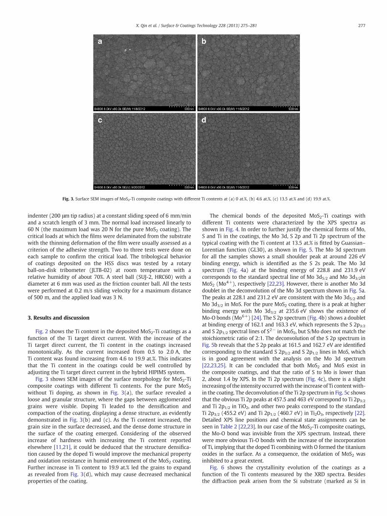
Fig. 3. Surface SEM images of MoS2-Ti composite coatings with different Ti contents at (a) 0 at.%, (b) 4.6 at.%, (c) 13.5 at.% and (d) 19.9 at.%.
277X. Qin et al. / Surface & Coatings Technology 228 (2013) 275–281
indenter (200 μm tip radius) at a constant sliding speed of 6 mm/minand a scratch length of 3 mm. The normal load increased linearly to60 N (the maximum load was 20 N for the pure MoS2 coating). Thecritical loads at which the films were delaminated from the substratewith the thinning deformation of the film were usually assessed as acriterion of the adhesive strength. Two to three tests were done oneach sample to confirm the critical load. The tribological behaviorof coatings deposited on the HSS discs was tested by a rotaryball-on-disk tribometer (JLTB-02) at room temperature with arelative humidity of about 70%. A steel ball (SUJ-2, HRC60) with adiameter at 6 mm was used as the friction counter ball. All the testswere performed at 0.2 m/s sliding velocity for a maximum distanceof 500 m, and the applied load was 3 N.
3. Results and discussion
Fig. 2 shows the Ti content in the deposited MoS2-Ti coatings as afunction of the Ti target direct current. With the increase of theTi target direct current, the Ti content in the coatings increasedmonotonically. As the current increased from 0.5 to 2.0 A, theTi content was found increasing from 4.6 to 19.9 at.%. This indicatesthat the Ti content in the coatings could be well controlled byadjusting the Ti target direct current in the hybrid HIPIMS system.
Fig. 3 shows SEM images of the surface morphology for MoS2-Ticomposite coatings with different Ti contents. For the pure MoS2without Ti doping, as shown in Fig. 3(a), the surface revealed aloose and granular structure, where the gaps between agglomeratedgrains were visible. Doping Ti leaded to the densification andcompaction of the coating, displaying a dense structure, as evidentlydemonstrated in Fig. 3(b) and (c). As the Ti content increased, thegrain size in the surface decreased, and the dense dome structure inthe surface of the coating emerged. Considering of the observedincrease of hardness with increasing the Ti content reportedelsewhere [11,21], it could be deduced that the structure densifica-tion caused by the doped Ti would improve the mechanical propertyand oxidation resistance in humid environment of the MoS2 coating.Further increase in Ti content to 19.9 at.% led the grains to expandas revealed from Fig. 3(d), which may cause decreased mechanicalproperties of the coating.
The chemical bonds of the deposited MoS2-Ti coatings withdifferent Ti contents were characterized by the XPS spectra asshown in Fig. 4. In order to further justify the chemical forms of Mo,S and Ti in the coatings, the Mo 3d, S 2p and Ti 2p spectrum of thetypical coating with the Ti content at 13.5 at.% is fitted by Guassian–Lorentian function (GL30), as shown in Fig. 5. The Mo 3d spectrumfor all the samples shows a small shoulder peak at around 226 eVbinding energy, which is identified as the S 2s peak. The Mo 3dspectrum (Fig. 4a) at the binding energy of 228.8 and 231.9 eVcorresponds to the standard spectral line of Mo 3d5/2 and Mo 3d3/2inMoS2 (Mo4+), respectively [22,23]. However, there is another Mo 3ddoublet in the deconvolution of the Mo 3d spectrum shown in Fig. 5a.The peaks at 228.1 and 231.2 eV are consistent with the Mo 3d5/2 andMo 3d3/2 in MoS. For the pure MoS2 coating, there is a peak at higherbinding energy with Mo 3d3/2 at 235.6 eV shows the existence ofMo-O bonds (Mo6+) [24]. The S 2p spectrum (Fig. 4b) shows a doubletat binding energy of 162.1 and 163.3 eV, which represents the S 2p3/2and S 2p1/2 spectral lines of S2− in MoS2, but S/Mo does not match thestoichiometric ratio of 2:1. The deconvolution of the S 2p spectrum inFig. 5b reveals that the S 2p peaks at 161.5 and 162.7 eV are identifiedcorresponding to the standard S 2p3/2 and S 2p1/2 lines in MoS, whichis in good agreement with the analysis on the Mo 3d spectrum[22,23,25]. It can be concluded that both MoS2 and MoS exist inthe composite coatings, and that the ratio of S to Mo is lower than2, about 1.4 by XPS. In the Ti 2p spectrum (Fig. 4c), there is a slightincreasing of the intensity occurredwith the increase of Ti contentwith-in the coating. The deconvolution of the Ti 2p spectrum in Fig. 5c showsthat the obvious Ti 2p peaks at 457.5 and 463 eV correspond to Ti 2p3/2and Ti 2p1/2 in TiO2, and other two peaks correspond to the standardTi 2p3/2 (455.2 eV) and Ti 2p1/2 (460.7 eV) in Ti2O3, respectively [22].Detailed XPS line positions and chemical state assignments can beseen in Table 2 [22,23]. In our case of the MoS2-Ti composite coatings,the Mo-O bond was invisible from the XPS spectrum. Instead, therewere more obvious Ti-O bonds with the increase of the incorporationof Ti, implying that the doped Ti combiningwith O formed the titaniumoxides in the surface. As a consequence, the oxidation of MoS2 wasinhibited to a great extent.
Fig. 6 shows the crystallinity evolution of the coatings as afunction of the Ti contents measured by the XRD spectra. Besidesthe diffraction peak arisen from the Si substrate (marked as Si in
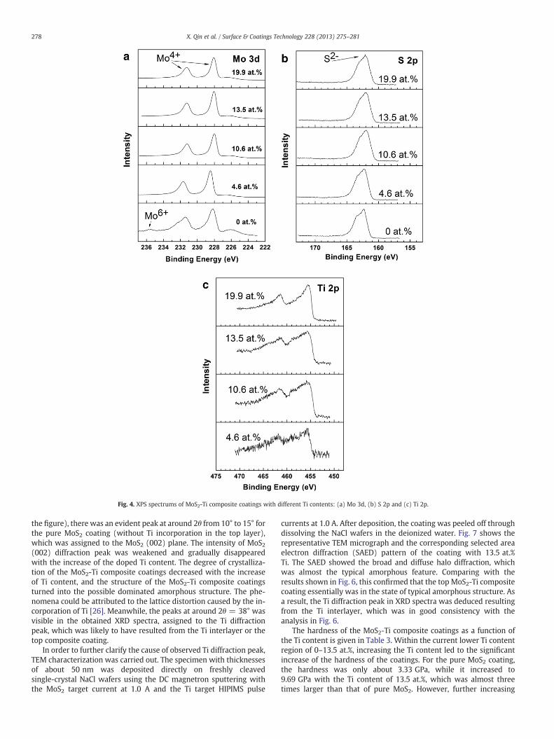
Fig. 4. XPS spectrums of MoS2-Ti composite coatings with different Ti contents: (a) Mo 3d, (b) S 2p and (c) Ti 2p.
278 X. Qin et al. / Surface & Coatings Technology 228 (2013) 275–281
the figure), there was an evident peak at around 2θ from 10° to 15° forthe pure MoS2 coating (without Ti incorporation in the top layer),which was assigned to the MoS2 (002) plane. The intensity of MoS2(002) diffraction peak was weakened and gradually disappearedwith the increase of the doped Ti content. The degree of crystalliza-tion of the MoS2-Ti composite coatings decreased with the increaseof Ti content, and the structure of the MoS2-Ti composite coatingsturned into the possible dominated amorphous structure. The phe-nomena could be attributed to the lattice distortion caused by the in-corporation of Ti [26]. Meanwhile, the peaks at around 2θ = 38° wasvisible in the obtained XRD spectra, assigned to the Ti diffractionpeak, which was likely to have resulted from the Ti interlayer or thetop composite coating.
In order to further clarify the cause of observed Ti diffraction peak,TEM characterization was carried out. The specimen with thicknessesof about 50 nm was deposited directly on freshly cleavedsingle-crystal NaCl wafers using the DC magnetron sputtering withthe MoS2 target current at 1.0 A and the Ti target HIPIMS pulse
currents at 1.0 A. After deposition, the coating was peeled off throughdissolving the NaCl wafers in the deionized water. Fig. 7 shows therepresentative TEM micrograph and the corresponding selected areaelectron diffraction (SAED) pattern of the coating with 13.5 at.%Ti. The SAED showed the broad and diffuse halo diffraction, whichwas almost the typical amorphous feature. Comparing with theresults shown in Fig. 6, this confirmed that the top MoS2-Ti compositecoating essentially was in the state of typical amorphous structure. Asa result, the Ti diffraction peak in XRD spectra was deduced resultingfrom the Ti interlayer, which was in good consistency with theanalysis in Fig. 6.
The hardness of the MoS2-Ti composite coatings as a function ofthe Ti content is given in Table 3. Within the current lower Ti contentregion of 0–13.5 at.%, increasing the Ti content led to the significantincrease of the hardness of the coatings. For the pure MoS2 coating,the hardness was only about 3.33 GPa, while it increased to9.69 GPa with the Ti content of 13.5 at.%, which was almost threetimes larger than that of pure MoS2. However, further increasing

Fig. 5. Decomposition of the Mo 3d (a), S 2p (b) and Ti 2p (c) spectral region of the typical coating with the 13.5 at.% Ti.
279X. Qin et al. / Surface & Coatings Technology 228 (2013) 275–281
Ti content to 19.9 at.% caused the hardness decrease to 6.82 GPa.Taking into account the structure densification dependence on theTi content, the hardness increase of the MoS2-Ti composite coatingcould be understood by the solid solution hardening effect [7]. Inthis case, the hardness firstly increased and reached to the maximumvalue due to the structure densification with a certain of saturationvalue of Ti content. Beyond of this threshold value of 13.5 at.%Ti, the overrich doped soft Ti atoms in turn caused the structuredeterioration and led to the decrease of hardness. Similar resultscould be found in the other study of MoS2-Ti composite coating[4,26].
To obtain the high adhesion is one of the major technologychallenges for sputtered MoS2 solid lubricating coatings on bearingsteel, which play the crucial role on the tribological property of thecoating. Table 3 shows the critical loads of the pure MoS2 andMoS2-Ti composite coatings on HSS substrate. The results showedthat all the MoS2-Ti composite coatings with different Ti contentowned much higher critical load than the pure MoS2 coating, andwithin the lower Ti content region of 0–13.5 at.%, increasing thedoped Ti content led to the significant increase of the critical load ofthe coatings. It can be deduced that Ti concentration seemed toplay a considerable role in coating adhesion. Previous studies [27]
Table 2XPS line positions and chemical state assignments.
Line Position (eV) Assignment
Mo 3d5/2 228.8 MoS2228.1 MoS
S 2p3/2 162.1 MoS2161.5 MoS
Ti 2p3/2 457.5 TiO2
455.2 Ti2O3
indicated that adhesion failure mechanisms displayed the filmcohesion failure at the beginning, followed by spalling betweencoating and buffer, then substrate. This improvement in coatingadhesion with increase in Ti content maybe attributed to thebombardment of more high-energy Ti particles, resulting in enhanceddensification and cohesion of the coating. There was also interdiffu-sion between MoS2-Ti composite layer and Ti interlayer depositedat the initial stage of coating preparation. The more bombardmentby Ti particles provided better bonding between coating and bufferand better adhesion [28]. It can be observed that maximum coatingadhesion was obtained with a critical load of 58 N for the 13.5 at.%Ti content, consistent with the results of hardness. The previousresearch by Bidev and Holmberg [29,30] showed that the adhesionintensified with the increase of film hardness. Thence, the critical
Fig. 6. XRD spectra of MoS2-Ti composite coatings.
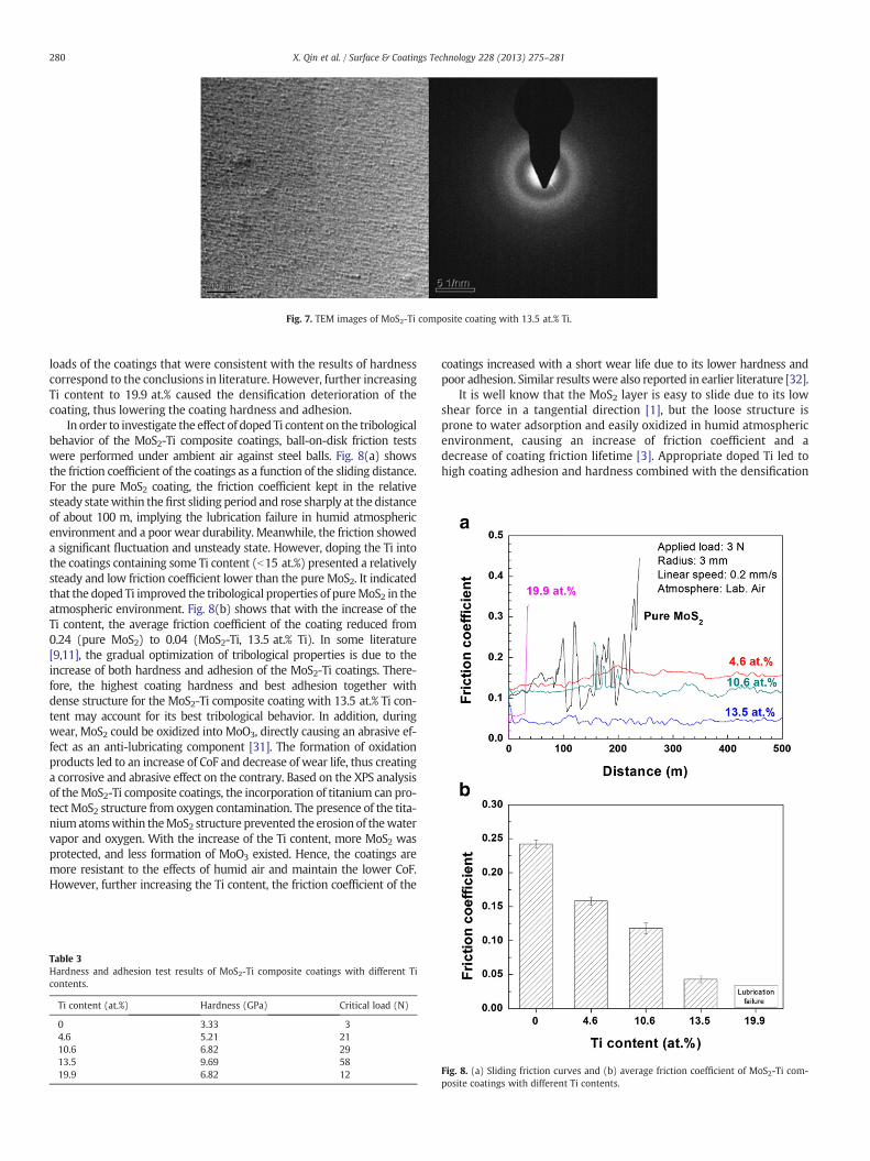
Fig. 7. TEM images of MoS2-Ti composite coating with 13.5 at.% Ti.
280 X. Qin et al. / Surface & Coatings Technology 228 (2013) 275–281
loads of the coatings that were consistent with the results of hardnesscorrespond to the conclusions in literature. However, further increasingTi content to 19.9 at.% caused the densification deterioration of thecoating, thus lowering the coating hardness and adhesion.
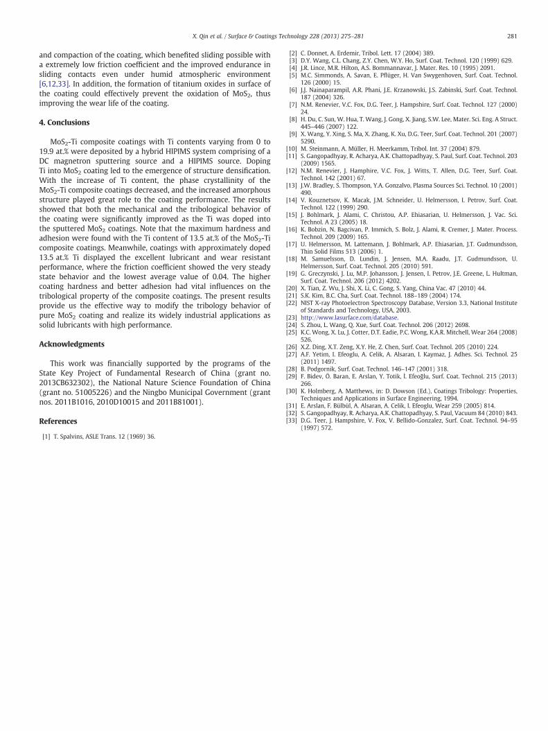
In order to investigate the effect of doped Ti content on the tribologicalbehavior of the MoS2-Ti composite coatings, ball-on-disk friction testswere performed under ambient air against steel balls. Fig. 8(a) showsthe friction coefficient of the coatings as a function of the sliding distance.For the pure MoS2 coating, the friction coefficient kept in the relativesteady statewithin thefirst sliding period and rose sharply at the distanceof about 100 m, implying the lubrication failure in humid atmosphericenvironment and a poor wear durability. Meanwhile, the friction showeda significant fluctuation and unsteady state. However, doping the Ti intothe coatings containing some Ti content (b15 at.%) presented a relativelysteady and low friction coefficient lower than the pure MoS2. It indicatedthat the doped Ti improved the tribological properties of pureMoS2 in theatmospheric environment. Fig. 8(b) shows that with the increase of theTi content, the average friction coefficient of the coating reduced from0.24 (pure MoS2) to 0.04 (MoS2-Ti, 13.5 at.% Ti). In some literature[9,11], the gradual optimization of tribological properties is due to theincrease of both hardness and adhesion of the MoS2-Ti coatings. There-fore, the highest coating hardness and best adhesion together withdense structure for the MoS2-Ti composite coating with 13.5 at.% Ti con-tent may account for its best tribological behavior. In addition, duringwear, MoS2 could be oxidized into MoO3, directly causing an abrasive ef-fect as an anti-lubricating component [31]. The formation of oxidationproducts led to an increase of CoF and decrease of wear life, thus creatinga corrosive and abrasive effect on the contrary. Based on the XPS analysisof theMoS2-Ti composite coatings, the incorporation of titanium can pro-tect MoS2 structure from oxygen contamination. The presence of the tita-niumatomswithin theMoS2 structure prevented the erosion of thewatervapor and oxygen. With the increase of the Ti content, more MoS2 wasprotected, and less formation of MoO3 existed. Hence, the coatings aremore resistant to the effects of humid air and maintain the lower CoF.However, further increasing the Ti content, the friction coefficient of the
Table 3Hardness and adhesion test results of MoS2-Ti composite coatings with different Ticontents.
Ti content (at.%) Hardness (GPa) Critical load (N)
0 3.33 34.6 5.21 2110.6 6.82 2913.5 9.69 5819.9 6.82 12
coatings increased with a short wear life due to its lower hardness andpoor adhesion. Similar results were also reported in earlier literature [32].
It is well know that the MoS2 layer is easy to slide due to its lowshear force in a tangential direction [1], but the loose structure isprone to water adsorption and easily oxidized in humid atmosphericenvironment, causing an increase of friction coefficient and adecrease of coating friction lifetime [3]. Appropriate doped Ti led tohigh coating adhesion and hardness combined with the densification
Fig. 8. (a) Sliding friction curves and (b) average friction coefficient of MoS2-Ti com-posite coatings with different Ti contents.
281X. Qin et al. / Surface & Coatings Technology 228 (2013) 275–281
and compaction of the coating, which benefited sliding possible witha extremely low friction coefficient and the improved endurance insliding contacts even under humid atmospheric environment[6,12,33]. In addition, the formation of titanium oxides in surface ofthe coating could effectively prevent the oxidation of MoS2, thusimproving the wear life of the coating.
4. Conclusions
MoS2-Ti composite coatings with Ti contents varying from 0 to19.9 at.% were deposited by a hybrid HIPIMS system comprising of aDC magnetron sputtering source and a HIPIMS source. DopingTi into MoS2 coating led to the emergence of structure densification.With the increase of Ti content, the phase crystallinity of theMoS2-Ti composite coatings decreased, and the increased amorphousstructure played great role to the coating performance. The resultsshowed that both the mechanical and the tribological behavior ofthe coating were significantly improved as the Ti was doped intothe sputtered MoS2 coatings. Note that the maximum hardness andadhesion were found with the Ti content of 13.5 at.% of the MoS2-Ticomposite coatings. Meanwhile, coatings with approximately doped13.5 at.% Ti displayed the excellent lubricant and wear resistantperformance, where the friction coefficient showed the very steadystate behavior and the lowest average value of 0.04. The highercoating hardness and better adhesion had vital influences on thetribological property of the composite coatings. The present resultsprovide us the effective way to modify the tribology behavior ofpure MoS2 coating and realize its widely industrial applications assolid lubricants with high performance.
Acknowledgments
This work was financially supported by the programs of theState Key Project of Fundamental Research of China (grant no.2013CB632302), the National Nature Science Foundation of China(grant no. 51005226) and the Ningbo Municipal Government (grantnos. 2011B1016, 2010D10015 and 2011B81001).
References
[1] T. Spalvins, ASLE Trans. 12 (1969) 36.
[2] C. Donnet, A. Erdemir, Tribol. Lett. 17 (2004) 389.[3] D.Y. Wang, C.L. Chang, Z.Y. Chen, W.Y. Ho, Surf. Coat. Technol. 120 (1999) 629.[4] J.R. Lince, M.R. Hilton, A.S. Bommannavar, J. Mater. Res. 10 (1995) 2091.[5] M.C. Simmonds, A. Savan, E. Pflüger, H. Van Swygenhoven, Surf. Coat. Technol.
126 (2000) 15.[6] J.J. Nainaparampil, A.R. Phani, J.E. Krzanowski, J.S. Zabinski, Surf. Coat. Technol.
187 (2004) 326.[7] N.M. Renevier, V.C. Fox, D.G. Teer, J. Hampshire, Surf. Coat. Technol. 127 (2000)
24.[8] H. Du, C. Sun, W. Hua, T. Wang, J. Gong, X. Jiang, S.W. Lee, Mater. Sci. Eng. A Struct.
445–446 (2007) 122.[9] X. Wang, Y. Xing, S. Ma, X. Zhang, K. Xu, D.G. Teer, Surf. Coat. Technol. 201 (2007)
5290.[10] M. Steinmann, A. Müller, H. Meerkamm, Tribol. Int. 37 (2004) 879.[11] S. Gangopadhyay, R. Acharya, A.K. Chattopadhyay, S. Paul, Surf. Coat. Technol. 203
(2009) 1565.[12] N.M. Renevier, J. Hamphire, V.C. Fox, J. Witts, T. Allen, D.G. Teer, Surf. Coat.
Technol. 142 (2001) 67.[13] J.W. Bradley, S. Thompson, Y.A. Gonzalvo, Plasma Sources Sci. Technol. 10 (2001)
490.[14] V. Kouznetsov, K. Macak, J.M. Schneider, U. Helmersson, I. Petrov, Surf. Coat.
Technol. 122 (1999) 290.[15] J. Bohlmark, J. Alami, C. Christou, A.P. Ehiasarian, U. Helmersson, J. Vac. Sci.
Technol. A 23 (2005) 18.[16] K. Bobzin, N. Bagcivan, P. Immich, S. Bolz, J. Alami, R. Cremer, J. Mater. Process.
Technol. 209 (2009) 165.[17] U. Helmersson, M. Lattemann, J. Bohlmark, A.P. Ehiasarian, J.T. Gudmundsson,
Thin Solid Films 513 (2006) 1.[18] M. Samuelsson, D. Lundin, J. Jensen, M.A. Raadu, J.T. Gudmundsson, U.
Helmersson, Surf. Coat. Technol. 205 (2010) 591.[19] G. Greczynski, J. Lu, M.P. Johansson, J. Jensen, I. Petrov, J.E. Greene, L. Hultman,
Surf. Coat. Technol. 206 (2012) 4202.[20] X. Tian, Z. Wu, J. Shi, X. Li, C. Gong, S. Yang, China Vac. 47 (2010) 44.[21] S.K. Kim, B.C. Cha, Surf. Coat. Technol. 188–189 (2004) 174.[22] NIST X-ray Photoelectron Spectroscopy Database, Version 3.3, National Institute
of Standards and Technology, USA, 2003.[23] http://www.lasurface.com/database.[24] S. Zhou, L. Wang, Q. Xue, Surf. Coat. Technol. 206 (2012) 2698.[25] K.C. Wong, X. Lu, J. Cotter, D.T. Eadie, P.C. Wong, K.A.R. Mitchell, Wear 264 (2008)
526.[26] X.Z. Ding, X.T. Zeng, X.Y. He, Z. Chen, Surf. Coat. Technol. 205 (2010) 224.[27] A.F. Yetim, I. Efeoglu, A. Celik, A. Alsaran, I. Kaymaz, J. Adhes. Sci. Technol. 25
(2011) 1497.[28] B. Podgornik, Surf. Coat. Technol. 146–147 (2001) 318.[29] F. Bidev, Ö. Baran, E. Arslan, Y. Totik, İ. Efeoğlu, Surf. Coat. Technol. 215 (2013)
266.[30] K. Holmberg, A. Matthews, in: D. Dowson (Ed.), Coatings Tribology: Properties,
Techniques and Applications in Surface Engineering, 1994.[31] E. Arslan, F. Bülbül, A. Alsaran, A. Celik, I. Efeoglu, Wear 259 (2005) 814.[32] S. Gangopadhyay, R. Acharya, A.K. Chattopadhyay, S. Paul, Vacuum 84 (2010) 843.[33] D.G. Teer, J. Hampshire, V. Fox, V. Bellido-Gonzalez, Surf. Coat. Technol. 94–95
(1997) 572.