surface & coatings technology - roma tre university stress... · a dept. of engineering...
TRANSCRIPT

Surface & Coatings Technology 205 (2010) 2393–2403
Contents lists available at ScienceDirect
Surface & Coatings Technology
j ourna l homepage: www.e lsev ie r.com/ locate /sur fcoat
Residual stress evaluation at the micrometer scale: Analysis of thin coatings by FIBmilling and digital image correlation
Alexander M. Korsunsky a,⁎, Marco Sebastiani b, Edoardo Bemporad b
a Dept. of Engineering Science, Univ. of Oxford, Parks Road, Oxford OX1 3PJ, United Kingdomb University of Rome “ROMA TRE”, Mechanical and Industrial Engineering Department, Via Vasca Navale 79, 00146 Rome, Italy
⁎ Corresponding author. Tel.: +44 1865 273043; fax:E-mail address: [email protected] (
0257-8972/$ – see front matter © 2010 Elsevier B.V. Aldoi:10.1016/j.surfcoat.2010.09.033
a b s t r a c t
a r t i c l e i n f oArticle history:Received 25 June 2010Accepted in revised form 18 September 2010Available online 25 September 2010
Keywords:Residual stressesFocused ion beam (FIB)Digital image correlation (DIC)Finite element modeling (FEM)Coatings
In this report, an optimised method for residual stress determination at the microscopic scale is presented.The newly proposed approach involves incremental Focused Ion Beam (FIB) milling of annular trenches atmaterial surface, combined with high resolution SEM imaging of a previously deposited marker pattern.Digital image correlation (DIC) analysis of the relative displacements between markers with respect to theundisturbed state provides a measure of strain relief. Results of finite element modeling show that theproposed configuration gives complete strain relief when the annular trench depth becomes comparable withthe diameter of the remaining stub, thus allowing analytical calculation of the average residual stress frommeasured strain components. Basing on results of modeling, the experimental methodology has beendeveloped and optimised for residual stress analysis in thin coatings. In order to cover a wide range of materialproperties and residual stress states, two different materials have been selected: TiN CAE-PVD coating (hardand stiff, with compressive residual stress) on WC–Co substrate, and also an Au MS-PVD coating (soft andcompliant, with tensile residual stress). The procedure for the optimization of FIB milling parameters isreported. Results are validated by comparison with residual stress evaluation by X-ray diffraction andcurvature measurement on the two different specifically selected PVD coatings.
+44 1865 273010.A.M. Korsunsky).
l rights reserved.
© 2010 Elsevier B.V. All rights reserved.
1. Introduction
Residual stresses play a crucial role in determining the deforma-tion behaviour and performance of engineering components andmaterials, from bulk alloys and composites used in construction andmanufacturing industries down to micro-mechanical MEMS/NEMSsystems and the stresses within individual grains of polycrystallineaggregates, thin films and coatings. Residual stresses exist across thescales, frommacro- to nano-, and their evaluationmust necessarily beperformed using appropriately sized probes. The traditional methodsof residual stress evaluation are limited in their spatial resolution tofractions of a millimetre, making them ill-suited to the study of e.g.intragranular stresses in polycrystalline systems with the grain size ofa few micrometers.
On the other hand, the rapid development of nano-science andnano-technology in recent decades calls for the development ofappropriate nano-scale (or at least sub-micron) analysis tools forresidual stress evaluation [1–5]. The applications where (sub)micron-scale residual stress measurement is in demand include nano-structures, nano-devices and nano-structured materials. A portable
and accessible residual stress methodology should be applicable notonly in research context, but preferably be reducible to proceduresthat would allow routine use in industry, including in the context ofproduction and quality control.
Residual stress evaluation techniques can be classified into non-destructive techniques, such as X-ray and neutron diffraction, anddestructive and semi-destructive methods that involve materialremoval and the measurement of consequent surface strain relief.
The spatial resolution of the classical methods of residual stressevaluation by X-ray diffraction using laboratory sources is limited to afraction of a millimetre. In most cases this is insufficient for the studyof intragranular stresses. X-ray beams that are many orders ofmagnitude better in terms of flux and parallelism are produced atsynchrotrons.
In recent years the development of micro-focus synchrotron X-raybeams has opened the way for stress evaluation at the micron andsub-micron scales. The key to the possibility of using this approach isthe availability of high intensity, high brightness, micro-focuspolychromatic X-ray beams only produced at third generationsynchrotron sources. X-ray beams generated by a bending magnetor an insertion device such as a wiggler or wavelength shifter arefocused on the sample by the use of Kirkpatrick–Baez (KB) achromaticmirrors, allowing the creation of beam spot on the sample less than100 nm in diameter. The wide bandwidth of the incident beamensures that the interaction between the incident beam and the
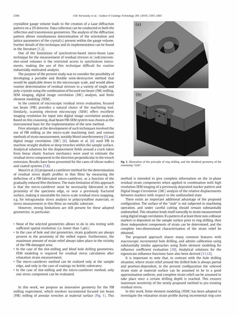
Fig. 1. Illustration of the principle of ring drilling, and the idealised geometry of theremaining “stub”.
2394 A.M. Korsunsky et al. / Surface & Coatings Technology 205 (2010) 2393–2403
crystalline gauge volume leads to the creation of a Laue diffractionpattern on a 2D detector. Data collection can be conducted in both thereflection and transmission geometries. The analysis of the diffractionpattern allows simultaneous determination of the orientation andlattice parameters of the crystal(s) present within the gauge volume.Further details of this technique and its implementation can be foundin the literature [1,2].
One of the limitations of synchrotron-based micro-beam Lauetechnique for the measurement of residual stresses in (sub)microm-eter-sized volumes is the restricted access to synchrotron instru-ments, making the use of this technique difficult for routineindustrially-motivated analysis.
The purpose of the present study was to consider the possibility ofdeveloping a portable and flexible semi-destructive method thatwould be applicable down to the microscopic scale, and would allowroutine determination of residual stresses in a variety of single andpoly-crystals using the combination of focused ion beam (FIB)milling,SEM imaging, digital image correlation (DIC) analysis, and finiteelement modeling (FEM).
In the context of microscopic residual stress evaluation, focusedion beam (FIB) provides a natural choice of the machining tool.Similarly, scanning electron microscopy (SEM) offers excellentimaging resolution for input into digital image correlation analysis.Based on this reasoning, dual beam FIB-SEM systemwas chosen as theinstrumental base for the implementation of the new method.
Prior attempts at the development of such techniques involved theuse of FIB milling as the micro-scale machining tool; and variousmethods of strainmeasurement, notablyMoiré interferometry [5] anddigital image correlation (DIC) [6]. Sabate et al. [6] used FIB tomachine straight shallow or deep trenches within the sample surface.Analytical solutions for the displacement fields around a crack takenfrom linear elastic fracture mechanics were used to estimate theresidual stress component in the direction perpendicular to the trenchextension. Results have been presented for the cases of silicon wafersand coated systems [7,8].
Massl et al. [9] proposed a cantilevermethod for the determinationof residual stress depth profiles in thin films by measuring thedeflection of a FIB-fabricated micro-cantilever, as a function of thegradually reduced film thickness. The main limitation of this approachis that the micro-cantilever must be necessarily fabricated in theproximity of the specimen edge, or near a previously fracturedsurface, making it unsuitable for micro-scale residual stress mapping,e.g. for intragranular stress analysis in polycrystalline materials, orstress measurement in thin films on metallic substrate.
However, strong limitations are still present for these adoptedgeometries, in particular:
• None of the selected geometries allows to do in situ testing withsufficient spatial resolution (i.e. lower than 1 μm);
• In the case of hole and slot geometries, strain gradients are alwayspresent in the proximity of the milled region. Furthermore, themaximum amount of strain relief always takes place in the vicinityof the FIB-damaged area;
• In the case of the slot-milling and blind hole drilling geometries,FEM modeling is required for residual stress calculation afterrelaxation strain measurement;
• The micro-cantilever method can be realized only at the sampleedge, and only in the case of coatings on brittle substrates;
• In the case of slot-milling and the micro-cantilever method, onlyone stress component can be evaluated.
In this work, we propose an innovative geometry for the FIBmilling experiment, which involves incremental focused ion beam(FIB) milling of annular trenches at material surface (Fig. 1). This
method is intended to give complete information on the in-planeresidual strain components when applied in combination with highresolution SEM imaging of a previously deposited marker pattern andDigital Image Correlation (DIC) analysis of the relative displacementsbetween markers with respect to the undisturbed state.
There exists an important additional advantage of the proposedconfiguration. The surface of the “stub” is not subjected to machiningoperation, and under careful cutting should remain substantiallyundisturbed. This situation lends itself naturally to strain measurementusing digital image correlation. If a pattern of at least three non-collinearmarkers is deposited on the sample surface prior to ring drilling, thenthree independent components of strain can be determined, and thecomplete two-dimensional characterisation of the strain relief beobtained.
The proposed approach shares many common features withmacroscopic incremental hole drilling, and admits calibration usingsubstantially similar approaches using finite element modeling forinfluence coefficient evaluation [10]. Analytical solutions for theeigenstrain influence functions have also been derived [11,12].
It is important to note that, in contrast with the hole drillingsituation, where strain relief around the drilled hole is always partialand position-dependent, in the present configuration the relievedstrain state at material surface can be assumed to be to a goodapproximation uniform; and complete strain relief can be assumed totake place once a certain drilling depth is reached. This ensuresmaximum sensitivity of the newly proposed method to pre-existingresidual stress.
In this work, finite element modeling (FEM) has been adopted toinvestigate the relaxation strain profile during incremental ring-core

2395A.M. Korsunsky et al. / Surface & Coatings Technology 205 (2010) 2393–2403
milling of a residually stressed coated surface, with the main objectiveof identify the optimal geometrical configuration for strain analysis, interms of stub's diameter and milling depth.
The experimental implementation of the ring drilling technique onthin coatings using the dual beam FIB-SEM system is then described.The selection of the method for surface patterning is discussed, alongwith the choice of ring drilling conditions.
Next, the application of digital image correlation analysis to thedetermination of strain relief due to ring drilling is described. Stressevaluation is achieved by comparison between FEM predictions forstrain relief, on the one hand, and the experimentally determinedincremental strain relief measured by digital image correlation on theother.
Finally, the results are reviewed and discussed, and comments aremade on the likely future developments of the novel approachproposed here.
2. Modeling strain relief from an annular trench
In preparation for the experimental implementation of FIB ringdrilling method for micro-scale residual stress analysis, finite elementsimulation of the surface strain relief due to incremental ring-coremilling over a residually stressed coated system has been carried out.
Relaxation strain aftermilling of annular trenches has been alreadystudied in the past by Finite Element Modeling for the case of themacro-scale ring-core method [13,14].
In this case, themain objective of the FEMmodelingwas to identifythe optimal geometrical conditions (i.e. size and depth of the trench)for the application of the ring-core geometry to residual stressanalysis at the micro-scale on thin coatings.
The details on the FEM procedure adopted in this work and thebasic equations of stress gradient analysis by the incremental ring-core method are reported in Appendix A.
In the following, the results are presented for the case of an equi-biaxial residual stress field (Eq. (A5), see Appendix A). This situationwas chosen because it is particularly relevant for the case of thincoatings on homogeneous substrate.
Fig. 2 illustrates the plot of computed strain relief curve for the caseof equi-biaxial constant through the thickness stress field (ascalculated by Eq. (A5)) for all the material properties combinationsconsidered here (d/t=1), and then normalised with respect to thebiaxial modulus E/(1−ν)) vs the trench depth normalised withrespect to the stub diameter (h/d). A unique master relaxation curve
Fig. 2. FEM modeled normalized stress relief as a function of normalized drilling depth.
was found to apply for all material property combinations consideredin this work. Another important observation is that the normalizedstress relief approaches unity for h/dN1, meaning that full stress relief(i.e. complete saturation) is achievedwhen the trench depth is at leastequal to its diameter.
This observation was made for all material property combinations,showing that complete saturation is achieved for h/dN1 indepen-dently of the elastic properties of the substrate.
It is important to note that the above conclusions are valid providedthe stub diameter (d) is equal to, or is smaller than the coatingthickness (t). In case of d/tN1, a dependence of the relief strain profileon the elastic properties of the substrate may be observed.
It is also worth noting that relief strain was found to be nearlyuniform over the surface of the stub, as expected. This situation issignificantly different from the conventional hole drilling geometry,where strain gradients are present in the vicinity of the edge of thehole. This aspect is particularly relevant in the case of FIBmilling, sincethe edges of the milled area are usually damaged by the ion beam andby material re-deposition effects [6,7].
We can then conclude that the measured strain reliefΔε̃ = ΔεðhÞjh≥d between the original (undisturbed) surface and thefully relieved surface of the stub of diameter d provides informationabout the average residual stress σ * within the sample surfacewithout any further need for Finite Element Modeling. Whencomplete strain relief Δε̃ is achieved, the equi-biaxial residual stressis simply found from
σ̃ = − EΔε̃ð1−vÞ: ð1Þ
For the consideration of non-equi-biaxial residual stress states, theresidual stresses are written in terms of maximum strain reliefsΔε̃1; Δε̃2 as follows:
σ̃1 = − Eð1−v2Þ Δε̃1 + vΔε̃2
� �
σ̃2 = − Eð1−v2Þ Δε̃2 + vΔε̃1
� �ð2Þ
Here indices “1” and “2” refer to the principal stress (and strain)directions at sample surface.
This result is very relevant in the field of residual stressmeasurement of thin films, an observation that has not been madein previous studies on the conventional ring-core method.
When the directions of the principal stresses are not known a priori,strain should be measured along three different directions and the in-plane principal stress components should be calculated by the Mohr'scircle, as usually performed in macro-scale hole drilling and ring-coremethods.
It is important to remind that the simplified Eqs. (1–2) hold whenthe geometry of the FIB-milled trench is close to the ideal one shownin Fig. 2.
Fig. 3 reports the normalized relaxation strain profile for the caseof the lateral slope of the stub being equal to 9°, in comparison withthe analogous curve obtained for the ideal case. The results show thata slight difference exists between the two cases, with the relaxationcurve being steeper in the ideal case. The actual slope of the stubshould be therefore measured in the experimental practice and thencorrected in the model. However, the observation that full saturationof strain relief is reached for h/dN1 remains valid also in case of thislateral slope being present, so that the use of Eqs. (1–2) can still beconsidered appropriate, provided the lateral slope of the stub does notexceed about 10°.
It is interesting to observe that the stress relief curve in Fig. 2 alsodisplays a maximum. This maximum relief has the relative magnitude

Fig. 4. Normalized stress relief as a function of normalized drilling depth (dashed curve—FE model; continuous curve — “master function” approximation).
Fig. 3. FEM modeling of the influence of lateral on relaxation strain profile during ring-milling over a residually stressed surface.
2396 A.M. Korsunsky et al. / Surface & Coatings Technology 205 (2010) 2393–2403
of 1.125 and corresponds to the relative trench depth of h/d~0.4,independently of the mechanical properties of the coating andsubstrate. At greater drilling depths the magnitude of the relaxationstrain begins to decrease until full saturation is reached. Thisinteresting phenomenon is likely to be associated with the Poissoneffect, and deserves further detailed investigation. It is also worthnoting that full relief is first achieved at relative drilling depth of onlyabout h/d=0.2. If this modeling result is validated experimentally, itmay provide an important practical short-cut for the implementationof this residual stress evaluation technique.
The observed shape of the relaxation curve explains why thenormalized trench depth h/d is usually limited to about 0.3–0.4 for theconventional incremental ring-core method [13,14], due to the loss ofsensitivity to stress gradients at higher milling depths.
The following main conclusions can be finally drawn from themodeling activities described here:
1. Ring-core milling over a residually stressed surface allows fullstress relaxation over the stub surface for h/d≥1 (i.e. aspect ratio ofthe stub≥1), meaning that average residual stress field can beeasily computed by Eqs. (1–2), thus avoiding any further need ofFEM modeling;
2. In case of thin films, this results is also independent on substrate'selastic properties, if the stub's diameter is equal to (or lower than)coating thickness (so no need of FEM modeling also for coatings)
3. The computed relaxation strain was found to be uniform over thesurface of the stub, in contrast to what usually happens for the holedrilling geometry.
4. On the other hand, when measurements are performed with themain aim of investigating depth gradients of stress, the shape of themeasured relaxation strain suggests that FIB ring drilling should bedivided into many small depth increments up to a maximumnormalized trench depth h/d~0.4; in this case, residual stress canbe calculated by Eq. (A2) after FEM analysis of calibrationcoefficient matrices Ani and Bni (see Appendix A), following theprocedure for stress profiling conventionally used for the macro-scale hole drilling and ring-core methods.
These conclusions drawn from the finite element modeling studyconfirm that the micro-scale ring-core approach should be well-suited to the study of residual stress states with (sub)micronresolution, provided it can be implemented practically by means ofFIB ring drilling to the depths at least equal to the diameter of theremaining stub (also equal to coating thickness in case of stressmeasurement in thin films). This should be followed by themeasurement of relief strain by high resolution SEM imaging andDigital Image Correlation (DIC) analysis.
2.1. Introduction of a material independent “master curve” for averagestress calculation by the ring-core method
In order to aid the interpretation further we develop here apractically convenient analytical approach to the data interpretationbased on the FE modeling results. For biaxial residual stress thatremains constant with depth, the shape of the strain relief curve wasfound to be universal, i.e. independent of the properties of the samplebeing studied, as reported in Fig. 2. This conclusion applied evenwhenthe sample consisted of a coating layer on a dissimilar substrate,provided that the stub diameter is kept close to the coating thicknessvalue. This is a very strong result, since it makes it possible to describethe shape of the master curve by a simple approximating function.Such function should allow scaling in terms of the maximum strainrelief magnitude, and also in terms of the depth normalizationconstant (in our case chosen to be the inner ring radius). Once suchsimple functional form was found, the procedure for residual stressevaluation should involve:
(i) Fitting the master curve function to the experimental data(ii) Determining the value of the maximum relief strain, and its
uncertainty(iii) Computing the residual stress value using Eq. (3).
The approximating master function is indicated in Fig. 4 by thecontinuous curve, while the FE calculation results are plotted using thedashed line. The formula for themaster function is also indicated in thefigure. The master function is expressed in terms of the normalizeddepth parameter z=(x /0.42d), where x is the drilling depth and d isthe outer diameter of the remaining stub. The complete relief strainΔε̃is contained in the master function expression as a scaling parameter.
Effectively, we now have a simple analytical expression thatencapsulates all the results of the FE simulation in simple and compactform. Note that the formula is valid within the range of interest ofnormalized depths up to the value of 2.
3. Experimental implementation
3.1. Deposition of coatings and preliminary characterisation
The materials used in the present study were a 3.8 μm TiN coatingdeposited on the WC–Co substrate by cathodic arc evaporationphysical vapour deposition (CAE-PVD) and a 1.5 μm Au coating on Si/SiO2 substrate deposited by DC sputtering PVD technique (voltage410 V, current 0.2 A). The deposition parameters for the TiN coatingare reported in [15]. The microstructures of both coatings areillustrated in Fig. 5a–b.

(a)
(b)
Fig. 5. Microstructures of the (a) the TiN coating on WC–Co substrate and (b) the Aucoating on Silicon substrate.
2397A.M. Korsunsky et al. / Surface & Coatings Technology 205 (2010) 2393–2403
The two coated systems were selected in order to perform aquantitative estimation of the resolution and sensitivity of theproposed technique for two distinct cases of soft-ductile and hard-brittle materials, where a transition from tensile to compressiveresidual stress is also expected.
The intrinsic hardness and elastic modulus of the two PVD coatingswere measured bymeans of nano-indentation (NanoIndenter G200—
Agilent technologies). Continuous Stiffness Measurement (CSM)method was used with a Berkovich indenter tip calibrated on certifiedfused silica reference sample at 200 nmmaximum penetration depth,0.05 s−1 constant strain rate, 10 s hold at peak load for creepcorrection, and 45 s hold at 90% for thermal drift correction. TheOliver and Pharr method [16] was adopted for hardness and elasticmodulus evaluation. Other test parameters were in accordance withthe 14577-1-2 ISO standards.
An average indentation modulus of 503±25 GPa for the TiNcoating and 74.5±7 GPa for the Au coating, respectively, weremeasured at a penetration depth of 80 nm (Poisson's ratios beingtaken from literature for both materials). Correction for pile-up wasadopted in the case of the Au coating by direct SEM contact areameasurement after nano-indentation testing.
The average residual stress inside the TiN coating was separatelymeasured using a D/max-RAPID Rigaku microdiffractometer with CuKα radiation, equipped with a cylindrical image plate (IP) detector andusing a collimator diameter of 300 μm.Residual stresseswere calculated
by the analysis of a single Debye ring and then using the conventionald-sin2ψ plot to calculate the average stress in the coating [17].
The residual stress state on the Au PVD coating was also measuredby the curvature measurement and application of the Stoneyequation [18].
3.2. Implementation of the FIB ring-drill procedure
In all cases, a thin platinum layer was deposited on the samplesurface by focused ion beam deposition. The function of thisadditional layer is to protect the sample surface during ring drilling,and to provide the surface for the creation of the displacementanalysis pattern via FIB milling.
As shown in Fig. 6a, a regular grid of small dots (diameter anddepth of about 60 nm) was milled in the platinum layer. A highresolution SEM micrograph of the pattern was acquired before ringdrilling (Fig. 6b), and in a step-wise fashion during the ring drillingexperiment (Fig. 6b–c). Particular care was taken at all times to avoidthe artefacts in displacement measurement that may be induced byelectron beam drift during SEM image acquisition.
By using high image resolution (up to 4096×3775 pixels) anddecreasing the scanning dwell time down to 1 μs, acceptablereliability of digital image acquisition was achieved. This manifesteditself in the absence of significant errors in the imaging of a calibratedobject, i.e. errors were maintained at levels lower than the nominalresolution of the SEM column at the magnification used. Quantitativeinterpretation of the images in the fast scanning direction deliveredthe best dimensional accuracy, while an error of about 0.2%(corresponding to the drift of 2 nm for a field of view of 1 μm) wasobserved when length measurement was performed in the slowscanning direction (vertical direction in Fig. 6b). Based on theseobservations, and in order to obtain consistent quantitative informa-tion about biaxial strain relaxation, the in-plane displacementcomponents over the surface area of the stub were evaluated fromimages obtained by rotating the sample stage to three fixed positions(0°, 45° and 90°) and acquiring three different micrographs at eachmilling step. Displacement components were evaluated in the fastscanning electron beam direction in each case.
The approach adopted allows one to use the equations for stresscalculation that are already available for the macro-scale hole drillingand ring-core methods.
FIB ring-core milling was performed at the current of 48 pA andthe voltage of 30 kV at the incremental milling depth step of 200 nm,adopting an outer-to-inner path of the ion beam to avoid material re-deposition over the pillar surface. The drift of the ion beam wascontinuously automatically monitored during milling and corrected ifnecessary. A series of regular cross-sections was made simultaneouslywith the ring drilling procedure in order to avoid re-depositionproblems over the pillar surface during FIB milling and to provide amore accurate measurement of the actual milling depth after eachstep. Figs 6(c) and 7(a) illustrate two different steps of the millingprocedure for the TiN coating.
A micrograph of one of the realized tests for the Au coating onSilicon substrate is reported in Fig. 7b. In this case, the diameter of thepillar was of the order of 1.5 μm (equal to the coating thickness).
It is important to note that the procedure described above wasperformed in multiple sessions (i.e. on different days) and at multiplelocations on the surface of the coated samples. No less than threeimplementations of the same procedure were used to obtain theresults. In all cases the repeatability and consistency of the resultswere found to be excellent, i.e. the variation of the results lay wellwithin the estimate of the error based on the statistics of the DigitalImage Correlation analysis (see below). The coatings on the samplesconsidered in these studies were nominally uniform. Within the errorbound defined by the experimental statistics, no variation of theresidual stress across the sample surface was observed.

(a) (b)
(c) (d)
Fig. 6. Illustration of the FIB operations and SEM high resolution imaging steps. (a) Deposition of a Pt (electron beam) 100 nm thick platinum layer and milling of a pattern of verysmall dots (diameter 50 nm). (b) High resolution SEM imaging of the reference patter before milling. (c) Incremental FIB milling. (d) High-resolution SEM imaging of the referencepatter after each milling step.
2398 A.M. Korsunsky et al. / Surface & Coatings Technology 205 (2010) 2393–2403
Based on the results of FEM modeling reported previously, boththe maximum milling depth and diameter of the pillars were fixed tobe equal to the coating thickness, in order to achieve complete stressrelief and at the same time to obtain a sufficiently large surface areaunaffected by FIB artefacts for the determination of strain relief.
Fig. 6b–d report the data for the TiN coating showing the initial andthe relieved patterns at the sample surface. These imageswere used asinput for the Digital Image Correlation (DIC) analysis of strain relief. Itis worth noting that no significant morphological change in the milleddot pattern was observed (note the bigger radius reference dotsvisible in Fig. 2b–d). Thus, no relevant artefacts due to the FIB millingprocess (such as re-deposition or surface damage) were induced onupper surface of the pillar.
A cross section of the pillar (Fig. 8) was milled as the final stage ofthe procedure in order to obtain a complete morphological andmicrostructural characterisation of the pillar volume, namely, the finalmilling depth, the actual slope of the pillar, and information aboutthe coating local microstructure, as well as the presence of defects(Fig. 8). The measured actual geometry of the stubs (including lateralslope) was used to create a model for FEM calibration. This allowedobtaining specific calibration curves for each pillar, and also identifiedthe relevant range of geometric parameters needed for sensitivityanalysis.
Some re-deposition of TiN is visible on the left-side of the pillar inFig. 8. This experimental evidence confirms that strain measurementin proximity of the edges is impeded by FIB-induced artefacts, asobserved in previously reported attempts to use slot and blind holegeometry [6,7]. This observation confirms the key advantage of theproposed geometry in comparison to the other solutions available inliterature, due to the fact that uniform strain relief occurs over arelatively large area substantially unaffected by FIB milling artefacts.
4. Digital image correlation analysis
The Digital Image Correlation (DIC) method of strain determina-tion has undergone rapid development over the last two decades, dueto the greatly increased availability of digital systems for imagingacross the scales. Alongside scanning electron microscopy, otherimaging modalities can be used, including Atomic Force Microscopy(AFM), Scanning Transmission X-ray Microscopy (STXM), and variousdigital capture methods for optical images. Although conventionalstrain gauge methods remain widespread in industrial and researchuse, non-contact image-based strain evaluation methods possessnumerous advantages. Perhaps the two most obvious ones are (i) thenon-contact nature of this method, and (ii) its scale-independence.

(a)
(b)
Fig. 7. Illustration of the resulted stress‐relieved “stubs” for (a) the TiN coating onWC–Co substrate and (b) the Au coating on silicon substrate.
2399A.M. Korsunsky et al. / Surface & Coatings Technology 205 (2010) 2393–2403
The principles of DIC in current use are connected with its originsin particle anemometry, where the purpose is to track the motion ofparticles through an optically observed flow. In solid mechanics
Fig. 8. Illustration of the geometry of the FIB-milled “stub”. Lateral slope is lower than5°. A large number of grains is involved in the relaxation strain process during materialremoval.
applications, particles are replaced with “speckled” surface patches,and their motion is traced. It is necessary to take into account the factthat the tracked patches (sub-regions) may themselves undergodeformation, and thus become different from their reference state.However, the most likely new location of a patch can be found bycomputing the correlation function between the reference patchimage and its various putative displaced versions. Themost likely newlocation (and hence displacement) of the patch is such that deliversthe maximum to the correlation function. In other words, thedisplacements are found as
u*; v*ð Þ = arg maxCðu; vÞ; ð3Þ
where C is the correlation function, u,v denote all possible displace-ments along the two coordinates in the image plane, and u*, v* is thefinal displacement solution that corresponds to the maximum of thecorrelation function.
By partitioning the image into multiple patches and repeating thisprocedure, it is possible to compile a displacement map. This map canbe subsequently differentiated numerically to determine strains. Notethat sub-pixel accuracy of displacement determination can beachieved [6].
In the present study a Matlab® implementation of the DICprocedure was used, making use of the library function cpcorr.Relative displacement values were found between the reference andmilled images for the patches centred on themilled dots in the surfacepattern. The calculation was repeated for multiple pairs of milled dots,and the average value of the overall strain was computed. Thesevalues of the strain relief observed at different stages of the ringdrilling procedure served as the input into the analysis procedure forstress evaluation described in the following section.
5. Residual stress evaluation and validation
An example of the experimentally obtained strain relief profile ispresented in Fig. 6 for the TiN PVD coating under investigation, whileaverage relaxation strains at maximum penetration depth (such thath/dN1) are reported in Table 1 (average data and error bars arecalculated from 6 different tests for both coatings). The magnitudes ofstrain relief components measured along three different directions atthe pillar surface are close, indicating that the residual stress stateinside the TiN coating is nearly equi-biaxial. Hence, Hooke's law forequi-biaxial plane stress conditions can be used for the evaluation ofaverage residual stress over the stub. Similar results were alsoobtained for the PVD Au coating on Si substrate. The measured reliefstrain values shown in Fig 9 are in close agreement with thenumerically predicted curve. Note that, similarly to the curvepredicted from FE simulations, the experimental stress relief profileshows a maximum, with a reduction of strain relief and thensaturation at higher drilling depths.
The statistical error of the strain relief evaluation by DIC wasestimated as follows. The dot pattern deposited on the samplesurface contains a large number of dots, as is apparent from themicrographic images (Fig. 6). The comparative analysis (betweendeformed and reference image) of the spacing for each pair of dotsprovides a means of strain evaluation. In this way, a statisticallyrepresentative array of strain values (typically N10) can be obtainedfor each stage of trench milling. The standard deviation of the strainvalue within this array was taken as a measure of the nominal strainerror.
The average in-plane strain relief values were also calculated byfitting the FEM-simulated relief curve reported in the first part of thisreport to the experimental strain data, using the elastic modulus ofthe coating measured by nano-indentation and assuming Poisson'sratio from literature. Some of the FEM models used in this study

Table 1Results of stress calculation for both PVD coatings under investigation. Comparison between analytical calculations (Eq. 1) and FEM modeling with slope of the stub.
Au coating on Si substrate TiN coating on WC–Co substrate
Measured relaxation strain at maximum depth (h/dN1) −0.002±0.0006 0.092±0.0008Residual stress, analytical (Eq. (1)) [MPa] +261.2±85.5 −6162.0±530.0Residual stress, FEM modeled with slope [MPa] No relevant slope detected −6046.0±514.0Residual stress, Independently measured [MPa] +280 (curvature method) −5840 (XRD, sin2ψ, σφ)
2400 A.M. Korsunsky et al. / Surface & Coatings Technology 205 (2010) 2393–2403
incorporated real geometry reflecting the actual slope of the stub, asdirectly evaluated in situ by SEM after FIB milling.
As reported in Table 1, in the case of the TiN coating the results ofthe FEM simulation were slightly different from the analytical ones,essentially due to the actual slope of the remaining stubs being of theorder of 2°.
A further possible source of disagreement may be the systematicerror in the determination of the surface position from which thetrench depth is measured. In order to address this issue, the fittingprocedure using the master curve function was repeated, but with theallowance for a shift of the zero-depth position. The result is shown inFig 10.
Note that allowing for the zero-depth shift results in a slightlyhigher value of relief strain. Although the two results obtained arestatistically in agreement, the zero-depth correction improves thequality of fit and results in a smaller error (b2%) in the determinationof the complete strain relief, and hence of the residual stress(compared to about 4% otherwise).
In the case of the Au coating, no significant slope of the pillars wasmeasured, and stress calculation results by the analytical procedureand FEM were essentially coincident.
On the basis of six repeated tests carried out for both coatings, thevalues of residual stresses in the coatings were found to be equal to−6.04±0.51 GPa for the CAE-PVD TiN coating and +261.2±85.5 MPafor the DC sputtered Au coating, as reported in Table 1. These results arein good agreement with the estimates obtained by XRD analysis:−5.84 GPa for the TiN coating (using the same elastic constants) and280 MPa for the Au coating (by curvaturemeasurement). Note also thatXRD data analysis contained a greater uncertainty due to the strongtexture of the TiN coating (Fig. A5).
Although the result for the compressive stress in the TiN coatingappears to be very large, it is not unusual to encounter such values in
Fig. 9. Experimentally measured relaxation strain on the TiN coating and fitting withthe finite element modeling prediction.
the literature for strong ceramic systems, such as TiN [19,20]. Incontrast, the residual stress magnitude for the metallic Au coating isquite low. Nevertheless, the method provides a good estimate of theresidual stress value, compared to independent measurement by adifferent technique [21].
Fig. 11 presents the calculated stress–depth profiles [4,13] for theTiN coating for the case of five calculation steps (Eq. (A5), after FEMevaluation of influence coefficients), showing that the compressiveequi-biaxial residual stress increases towards the coating/substrateinterface. This deduced stress gradient can be correlated with the TiN
Fig. 10. The evaluation of complete strain relief (a) by master curve fitting, and (b) bymaster curve fitting with zero-depth shift.

Fig. 11. Depth profiling of residual stress for the TiN coating.
2401A.M. Korsunsky et al. / Surface & Coatings Technology 205 (2010) 2393–2403
coating microstructure illustrated in Fig. 5(a) and Fig. 8. Coarsercolumnar grains are observed in the near-surface regions, while amuch finer microstructure is evident near the coating/substrateinterface. Progressive reduction of the intrinsic stresses is thereforelikely to occur during film deposition, as a consequence of columnargrain growth.
Other possible explanations could be put forward for the observedsmall disagreement between the experimentally measured strainvalues and the FEM predicted relaxation curve (Fig. 9), e.g. theinhomogeneity of stress within the coating layer.
Finally, it is important to note that some inaccuracies in the stressprofile evaluation highlighted in Fig. 11 are due to the uncertainties inthe actual trench depth measurement. These uncertainties are relatedto the high surface roughness of the TiN PVD coating analysed. Notingthe steep slope of the relief curve for the pillar geometry at lowmillingdepths, a significant error in stress evaluation close to the surface mayarise even due to relatively small errors in the depth measurement.Note, however, that the obtained stress gradient is in good agreementwith the microstructural observations and with other XRD stressprofiles for thin coatings reported in the literature [16,17].
Further studies are nowongoing to evaluate the optimal geometricalconfiguration (i.e. diameter of the pillar and maximum drilling depthwith respect to coating thickness and surface roughness) for the analysisof stress gradients in thin coatings.
Another microstructural effect to be considered is represented bythe grain-boundary residual stresses that are known to develop in thefirst stages of the growth phase [13,14]. It is known from the literaturethat a columnar grain structure can give a tensile residual stress stateat the grain boundaries: this stress component could remainincompletely relaxed after FIB milling, but is not accounted for in ahomogeneous FE model. However, the tensile stress component atgrain boundaries is known to be always significantly lower than thestress components coming from surface ion bombardment andthermal expansion mismatch between coating and substrate.[13,14]
At this point, some further discussion is necessary of theassumptions adopted during modeling. The adoption of Eq. (1–2)and all modeling activities for stress calculation are based on theassumptions that (1) the elastic properties of the analyzed coating ishomogeneous and isotropic and (2) that continuum mechanicsremains valid at the considered scale.
An SEM micrograph of the TiN coating is reported in Fig. 5(a). Astrong columnar microstructure is evident. This indicates that someinaccuracies in stress calculation could arise as a consequence incorrectestimation of the actual anisotropic elastic constants of the coating.
Nevertheless, the FEG-SEM cross section of the stress relievedpillar (Fig. 8) also shows that the average size of the pillar is usuallymuch greater than the average grain size of the coating. In addition,the evaluation of elastic modulus by nano-indentation also gives anaverage over a large number of grains.
Therefore, the assumption of isotropic elastic behaviour for thecoating could be defended as a reasonable choice, at least at the scaleconsidered, where grain boundaries do not play a significant role inthe mechanical deformation process.
It is important to note also that the use of similar elastic constantsandgaugevolumes guarantees the consistencybetween residual stressvalues measured by the XRD-sin2ψ and nano-indentation method.
6. Discussion and conclusions
In the present report we presented a new methodology forresidual stress determination at themicro-scale by the combination ofFIB ring drilling, SEM imaging, DIC strain analysis, and FEM simulationof stress–strain relief in residually stressed surfaces. The results ofstress evaluation in two different coated systems were presented, anda good agreement was found with the estimates obtained by otherconventional techniques. In both cases, nearly equi-biaxial stressstates were observed. In addition, an estimation of the stress gradientthrough the coating thickness was shown to be possible, althoughfurther work is required in this respect, and is ongoing. The presentstudy contains some significant developments over the existing state-of-the-art.
The ring-core milling geometry chosen in the present approach hasbeen shown (through reasoning and numerical simulation) to beuniquely effective in providing complete, biaxial, substantially uniformsurface strain relief over significant areas available for microscopicimaging. This is a fundamental improvement over previous attempts,where steep strain gradients were created during the milling experi-ment. Moreover, in previous studies the greatest strain relief valuesinvariably arose close to themilled trenches,where surface damage andmodification occurred during milling, thus preventing accurate straindetermination.
The combination of FIB milling and SEM imaging within a singleexperiment ensures the ease and efficiency of use of the presentmethod, since it does not require the laborious and time-consumingtransfer of samples between instruments. In fact, the currentprocedure can be successfully automated for systematic batch moderesidual stress mapping across significant areas.
Finite element simulations were carried out of the strain reliefcaused by ring drilling in residually stressed surfaces, showing thatcomplete stress relief is achieved for h/d≥1, thus allowing to directlyevaluate the average residual stress from the measured strain with noneed of FEM simulations.
A number of other interesting peculiarities were also observed, suchas the steep, approximately linear dependence of the strain relief on themilling depth at low penetrations, followed by a maximumand subsequent reduction to a constant value. The observation of thisbehaviour offers new insight that can be effectively used to developimproved, more precise depth-resolving stress evaluation procedures.
The approach can be readily generalised to the analysis of non-equi-biaxial residual stress states, since the DIC evaluation of strainrelief in multiple directions can be readily extracted from micro-scopic images. The present paper thus provides an in-depth, detaileddescription of the method that we now propose to call "micro-ring-core" (MRC) [22]. The principal advantage of this technique overpreviously reported approaches is its ability to determine local residualstresses in (poly)crystalline and amorphous materials at micron andsub-micron scales.
Acknowledgements
Authors would like to acknowledge Daniele De Felicis for technicalassistance during FIB analyses, performed at the interdepartmentallaboratory of electron microscopy of university of Roma Tre, RomeItaly (http://www.lime.uniroma3.it), and Prof. Laura Depero (Univer-sity of Brescia) for XRD residual stress measurements.

Fig. A1.Detail of theaxisymmetric FEMmodel of the ringdrillingprocedure: step20of 30.
2402 A.M. Korsunsky et al. / Surface & Coatings Technology 205 (2010) 2393–2403
Appendix A. Details of the FEM developed procedure for averagestress and stress gradient analysis on thin coatings by theincremental ring-core method
Let Cartesian axes x and y be associated with the sample surface,and axis z with the surface normal. Since at the sample surface thetractions vanish, the out-of-plane normal stress σz=0.
One of the most widely used approaches to the study of surfacerelaxation strain after incremental material removal is represented bythe integral method proposed by Schajer [4] for the hole drillinggeometry and generalised to the ring-core geometry by Ajovalasitet al. [13]
In this approach, the measured strain relief ε(h) in a particularradial direction over the surface of the stub due to a trench of depthh is given by the integral of the infinitesimal strain relief componentsdue to the removal of tractions at all depths in the range 0≤H≤h:
Δε hð Þ = ∫h
0fA H; hð Þ σ1 hð Þ + σ2 hð Þ½ �
+ B H; hð Þ σ1 Hð Þ−σ2 Hð Þ½ � cos2αk Hð ÞgdHðA1Þ
Here Δε(h) is the strain relieved as measured at the surface aftermilling to depth h, σ1(H) and σ2(H) are the residual principal stressesacting at depth H, α is the angular coordinate measured anticlockwisefrom the maximum principal stress direction to the measuringdirection, and A(H, h), B(H, h) are the influence functions, which areusually determined by finite element modeling. If the milling isdivided into n finite increments, Eq. (A1) can be written as follows:
Δ�n = ∑ni = 1Ani σ1i + σ2ið Þ + ∑n
i = 1Bni σ1i−σ2ið Þ cos 2αi ðA2Þ
where σ1i and σ2i are the residual principal stresses in the ith layer andαi is the angle from the stress σ1i to the measuring direction, Ani, andBni are the influence coefficients which relate the strains relaxed at thesurface when the groove has n depth increments to the principalstresses acting in the i layer.
Residual stress can be therefore evaluated after calculation of thetwo matrices of calibration coefficients Ani, and Bni, which is usuallyperformed by finite element modeling [13].
In the case of macroscopic hole drilling and ring-core methods,relaxation strain measurement is usually performed along threedifferent radial directions (e.g. by a strain gauge rosette), in order todetermine all in-plane stress components.
Note also that the influence functions, when expressed in the formof Eqs. (1–2), also depend on material properties.
To evaluate the coefficient Ani, it is sufficient to consider anaxisymmetric model subjected to an hydrostatic calibration stressfield (σ1=σ2 in Eq. (A2)), so the coefficient Ani, can be calculated as:
Ani =Δεni2σ1
ðA3Þ
On the other hand, calibration coefficient Bni, can be obtained byimposing a pure shear calibration stressfield (σ2=−σ1 in Eq. (A2)), by:
Bni =Δεni2σ1
ðA4Þ
Coefficients Bni are also calculated by an axisymmetric FEMmodel,by using axisymmetric elements which also admit non-axisymmetricloading [13,14].
In case of equi-biaxial residual stress field (i.e. σ1i=σ2i=σi, at anygiven depth from surface), Eq. (A2) reduces to:
Δ�n = ∑ni = 12Ani⋅ σið Þ ðA5Þ
In this case, only coefficients Ani need to be determined.This situation is particularly relevant to the case of residual stress
analysis in thin coatings on flat substrate, where an equi-biaxialstress state is usually expected due to the uniform growth of the film[15].
Previous studies [13] have shown that, at a fixed maximumdepth, the errors in stress calculations depend on the amount and onthe distribution of the n calculation increments, with the optimalsteps sequence obtained by imposing the condition Ann=const[13,14].
In this work, commercial finite element analysis package ANSYS9.0 was used for the FEM analysis of relaxation strains after FIB drillingof annular trenches over a residually stressed surface. An axisym-metric model was created consisting of a stiff residually stressedcoating on a dissimilar substrate.
Fig. A1 illustrates some of the cylindrical models meshed usingquadratic temperature–displacement axisymmetric elements(Plane83 in ANSYS, which also allow non-axisymmetric loading forcalculation of influence coefficients Bni) representing a coating layerand a substrate block. The calibration coefficient matrices Ani and Bnican be therefore calculated by applying in the model a unit pure in-plane biaxial stress and a pure shear calibration stress, and the use ofEqs. (A3) and (A4), respectively [4,13].
The incremental ring drilling process is simulated by theprogressive removal of elements and illustrated in Fig. A2 for thecase n=3, where the applied calibration pressures are shown. Thediameter of the remaining stub (d) was fixed equal to coatingthickness t, so that d/t=1.
The material properties of both coating and substrate were variedin order to reproduce the most commonly encountered situations incase of thin coatings. The ratio of elastic moduli between coating andsubstrate (Ec/Es) was varied from 0.1 to 100 (0.1, 1, 10, and 100),while the Poisson ratios of both the coating and substrate (νc, νs) werevaried from 0.25 to 0.35 (0.25, 0.30, and 0.35), for a total of 36 realizedmodels.
The influence of the lateral slope of the stub (which is likely tohappen in case of FIB milling) was also considered via thedevelopment of specific models (see Fig. A3).

Fig. A3. Detail of the axisymmetric FEM model with arbitrary slope: step 20 of 30.
Fig. A2. Illustration of Finite Element simulation steps for the through‐thickness stress profile evaluation. Countour plot (FEM) of the stress rearrangement after ring-drilling on aresidually strerssed surface. It is worth noting that the upper surface of the remaining pillar is completely stress releived if h/d >1.
2403A.M. Korsunsky et al. / Surface & Coatings Technology 205 (2010) 2393–2403
References
[1] J.-S. Chung, G.E. Ice, J. Applied Physics 86 (1999) 5249.[2] B.C. Larson, W. Yang, G.E. Ice, J.D. Budai, J.Z. Tischler, Nature 415 (2002) 887.
[3] P.J. Withers, H.K.D.H. Bhadeshia, Mater. Sci. Technol. 17 (2001) 355.[4] G.S. Schajer, J. Eng. Mater. Technol. 110 (1988) 338.[5] H. Du, H. Xie, Z. Guo, B. Pan, Q. Luo, C. Gu, H.C. Jiang, L.J. Rong, Opt. Lasers Eng. 45
(2007) 1157.[6] N. Sabaté, D. Vogel, A. Gollhardt, J. Keller, C. Cané, I. Gràcia, J.R. Morante, B. Michel,
Micromech. Microeng. 16 (2006) 254.[7] N. Sabaté, D. Vogel, A. Gollhardt, J. Marcos, I. Gràcia, C. Cané, B.N. Michel,
Nanotechnology 17 (2006) 5264.[8] A.M. Korsunsky, S. Cherian, R. Raiteri, R. Berger, Sens. Actuators, A 139 (2007) 70.[9] S. Massl, J. Keckes, R. Pippan, Acta Mater. 55 (2007) 4835.
[10] G.S. Schajer, M.B. Prime, ASME Journal of Engineering Materials and Technology128 (2006) 375.
[11] A.M. Korsunsky, J. Mech. Phys. Solids 43 (1995) 1221.[12] R.J.H. Paynter, D.A. Hills, A.M. Korsunsky, Int. J. Solids Struct. 44 (2007) 6653.[13] G.S. Schajer, J. Eng. Mater. Technol. 110 (1988) 338.[14] A. Ajovalasit, G. Petrucci, B. Zuccarello, J. Eng. Mater. Technol. 118 (1996) 224.[15] E. Bemporad,M. Sebastiani, F. Casadei, F. Carassiti, Surf. Coat. Technol. 201 (2007) 7652.[16] W.C. Oliver, G.M. Pharr, J. Mater. Res. 7 (1992) 1564.[17] M. Gelfi, E. Bontempi, R. Roberti, L.E. Depero, Acta Mater. 52 (2004) 583.[18] G.G. Stoney, Proc. R. Soc. Lond. A 82 (1909) 172.[19] G.C.A.M. Janssen, Thin Solid Films 515 (2007) 6654.[20] R. Daniel, K.J. Martinschitz, J. Keckes, C. Mitterer, Acta Mater. 58 (2010) 2621.[21] G. Chen, D. Singh, O. Eryilmaz, J. Routbort, B.C. Larson, W. Liu, Appl. Phys. Lett. 89
(2006) 172104.[22] A.M. Korsunsky, M. Sebastiani, E. Bemporad, Mater. Letters 63 (2009) 1961.