surface acoustic wave sensors in mechanical engineering
TRANSCRIPT
© Faculty of Mechanical Engineering, Belgrade. All rights reserved FME Transactions (2010) 38, 11-18 11
Received: November 2009, Accepted: January 2010 Correspondence to: Dr Marija Hribšek Institute Goša, Milana Rakića 35, 11000 Belgrade, Serbia E-mail: [email protected]
Marija F. Hribšek Professor
Institute Goša, Belgrade
Dejan V. Tošić Associate Professor
University of Belgrade School of Electrical Engineering
Miroslav R. Radosavljević
Professional Adviser Institute Goša, Belgrade
Surface Acoustic Wave Sensors in Mechanical Engineering Surface acoustic wave (SAW) sensors are used for identification and measuring of physical quantities such as temperature, pressure, torque, acceleration, tire-road friction, humidity, etc. They do not need additional power supply for the sensor elements and may be accessed wirelessly, enabling the use in harsh indoor/outdoor environments. Types, operating principles and analysis of SAW sensors are explained. A few application examples of the wireless measurements in automotive and railway vehicles are presented. Keywords: SAW sensor, wireless sensor, transponder, temperature sensor, pressure sensor.
1. INTRODUCTION
In the last thirty years surface acoustic wave (SAW) devices have found diverse applications outside their conventional fields of application – communications and signal processing – as identification tags, chemical and biosensors, and as sensors of different physical quantities. They are used in consumer and highly professional devices and systems. The SAW sensors are passive elements (they do not need power supply) and can be accessed wirelessly, enabling remote monitoring in harsh environment. They work in the frequency range of 10 MHz to several GHz. They have the rugged compact structure, outstanding stability, high sensitivity, low cost, fast real time response, extremely small size (lightweight), and their fabrication is compatible with CMOS and micro-electro-mechanical (MEMS) integrated circuits technology [1-7].
The SAW sensors are used for identification of moving object and parts (so called ID tags) and wireless measuring of temperature, pressure, stress, strain, torque, acceleration, tire-road friction, and humidity.
The SAW sensors are well suited for measuring pressure in car and truck tires and tire-road friction monitoring. Their characteristics offer advantages over technologies such as capacitive and piezoresistive sensors, which require operating power and are not wireless. A SAW pressure sensor weighing less than 1 g, integrated into a car tire has a resolution of 5033.17 Pa [8]. Such a system allows the operator to view the pressure in each tire from the comfort of the cabin. Correctly inflated tires lead to improved safety, greater fuel efficiency, and longer tire life. This technology is particularly interesting for the new run-flat (also called zero pressure or extended mobility) tire market.
Surface acoustic waves were discovered in 1885 by Lord Rayleigh, and are often named after him: Rayleigh waves [9]. A surface acoustic wave is a type of mechanical wave motion which travels along the surface of a solid material. Rayleigh showed that SAWs
could explain one component of the seismic signal due to an earthquake, a phenomenon not previously understood. The velocity of acoustic waves is typically 3000 m/s, which is much lower than the velocity of the electromagnetic waves.
All acoustic wave devices and sensors use a piezoelectric material, such as quartz crystal, to generate the acoustic wave. Piezoelectricity was discovered by Pierre and Paul-Jacques Curie in 1880, received its name in 1881 from Wilhelm Hankel, and remained largely a curiosity until 1921, when Walter Cady discovered the quartz resonator for stabilizing electronic oscillators [10]. Piezoelectricity is the production of electrical charges by the imposition of mechanical stress. The phenomenon is reciprocal. Applying an appropriate electrical field to a piezoelectric material creates a mechanical stress. In piezoelectric acoustic wave sensors an oscillating electric field is used to create a mechanical wave, which propagates through the substrate and is then converted back to an electric field for measurement.
The first SAW device was actually made in 1965 by White and Voltmer [11]. They found out how to launch a SAW in a piezoelectric substrate by an electrical signal. Starting around the year 1970, SAW devices were developed for pulse compression radar, oscillators, and bandpass filters for TV sets and professional radio.
In the 1980s the rise of mobile radio, particularly for cellular telephones, caused a dramatic increase in demand for filters. New high-performance SAW filters emerged and vast numbers are now produced, around 3 billion annually.
The first part of this paper deals with the principles of operation, analysis, and design methods of SAW devices and sensors. In the second part various types of SAW sensors, their capabilities and applications in mechanical systems and vehicles are presented.
2. BASIC PRINCIPLE OF OPERATION OF SAW
DEVICES
The operation of the SAW device is based on acoustic wave propagation near the surface of a piezoelectric solid. This implies that the wave can be trapped or otherwise modified while propagating. The displacements decay exponentially away from the
12 ▪ VOL. 38, No 1, 2010 FME Transactions
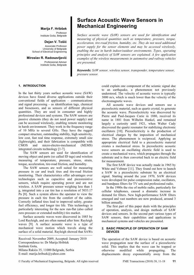
surface, so that the most of the wave energy (usually more than 95 %) is confined within a depth equal to one wavelength. The surface wave can be excited electrically by means of an interdigital transducer (IDT) [11]. A basic SAW device consists of two IDTs on a piezoelectric substrate such as quartz, Fig. 1. The input IDT launches and the output IDT receives the waves.
Figure 1. The basic structure of a SAW device
The interdigital transducer consists of a series of interleaved electrodes made of a metal film deposited on a piezoelectric substrate as shown in Figure 1 [11-14]. The width of the electrodes usually equals the width of the inter-electrode gaps giving the maximal conversion of electrical to mechanical signal, and vice versa. The minimal electrode width which is obtained in industry is around 0.3 µm, which determines the highest frequency of around 3 GHz.
The commonly used substrate crystals are: quartz, lithium niobate, lithium tantalate, zinc oxide and bismuth germanium oxide. They have different piezoelectric coupling coefficients and temperature sensitivities. The ST quartz is used for the most temperature stable devices.
A sinusoidal voltage v of frequency f applied to the input IDT forms an electric field which, through the piezoelectric effect causes a strain pattern of periodicity 2d, where d denotes the distance between the centers of the electrodes. If the frequency f is such that 2d is close to the surface wave wavelength, surface wave will be launched in two opposite directions away from the transducer. The surface wave causes the corresponding electric field in the output transducer and thus the voltage at the impedance ZL.
The wave velocity is a function of the substrate material and is in the range of 1500 m/s to 4800 m/s, which is 105 times lower than the electromagnetic wave velocity. This enables the construction of a small size delay line of a considerable delay.
The input and output transducers may be equal or different. It depends upon the function which the SAW device has to perform. Usually, they differ in electrode’s overlaps, number and sometimes positioning.
The magnitude of the output signal is the function of the ratio of the signal’s wavelength and the distance 2d. If the distance 2d is equal to the wavelength, the magnitude of the output voltage is maximal. The corresponding frequency is then called the centre or synchronous frequency of the device. The magnitude of the output voltage decays as the frequency shifts from the centre frequency. It means that, basically, a SAW device is a transversal bandpass filter. In transversal
filters the phase characteristic is a function of the distances between the electrodes and the amplitude characteristic is a function of the electrodes number and lengths. The IDT geometry is capable of almost endless variation, leading to a wide variety of devices.
If the electrodes are uniformly spaced as in Figure 1, the phase characteristic is a linear function of frequency, e.g., the phase delay is constant in the appropriate frequency range. This type of the SAW device is than called delay line.
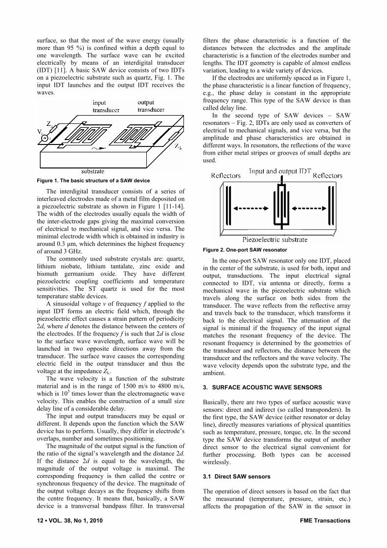
In the second type of SAW devices – SAW resonators – Fig. 2, IDTs are only used as converters of electrical to mechanical signals, and vice versa, but the amplitude and phase characteristics are obtained in different ways. In resonators, the reflections of the wave from either metal stripes or grooves of small depths are used.
Figure 2. One-port SAW resonator
In the one-port SAW resonator only one IDT, placed in the center of the substrate, is used for both, input and output, transductions. The input electrical signal connected to IDT, via antenna or directly, forms a mechanical wave in the piezoelectric substrate which travels along the surface on both sides from the transducer. The wave reflects from the reflective array and travels back to the transducer, which transforms it back to the electrical signal. The attenuation of the signal is minimal if the frequency of the input signal matches the resonant frequency of the device. The resonant frequency is determined by the geometries of the transducer and reflectors, the distance between the transducer and the reflectors and the wave velocity. The wave velocity depends upon the substrate type, and the ambient.
3. SURFACE ACOUSTIC WAVE SENSORS
Basically, there are two types of surface acoustic wave sensors: direct and indirect (so called transponders). In the first type, the SAW device (either resonator or delay line), directly measures variations of physical quantities such as temperature, pressure, torque, etc. In the second type the SAW device transforms the output of another direct sensor to the electrical signal convenient for further processing. Both types can be accessed wirelessly.
3.1 Direct SAW sensors
The operation of direct sensors is based on the fact that the measurand (temperature, pressure, strain, etc.) affects the propagation of the SAW in the sensor in
FME Transactions VOL. 38, No 1, 2010 ▪ 13
attenuation and delay, respectively. If the sensor is heated, stretched or compressed or if it is loaded to be bent, the substrate’s length and its elasticity constants are changed. These changes cause velocity and phase delay variations, which then proportionally change the centre and resonant frequency, attenuation and time delay of the device.
Time delay τ of the SAW delay line sensor, Fig. 1 is the ratio of acoustical length L (distance between the first electrodes of the input and output transducers) and SAW velocity v. In the known sensor applications, L and v are changed due to a temperature change, mechanical stress, and strain, or because of a mass loading from a thin surface layer. Therefore, the relative change of the delay due to the variation of the measurand y can be expressed as follows:
d 1 1 d dyL v y y
L y v yττ
⎛ ⎞∂ ∂= − = γ⎜ ⎟∂ ∂⎝ ⎠
, (1)
where γy can be called the delay sensitivity with respect to y. It is determined by the orientation and type of crystalline material used to fabricate the sensor [2,15].
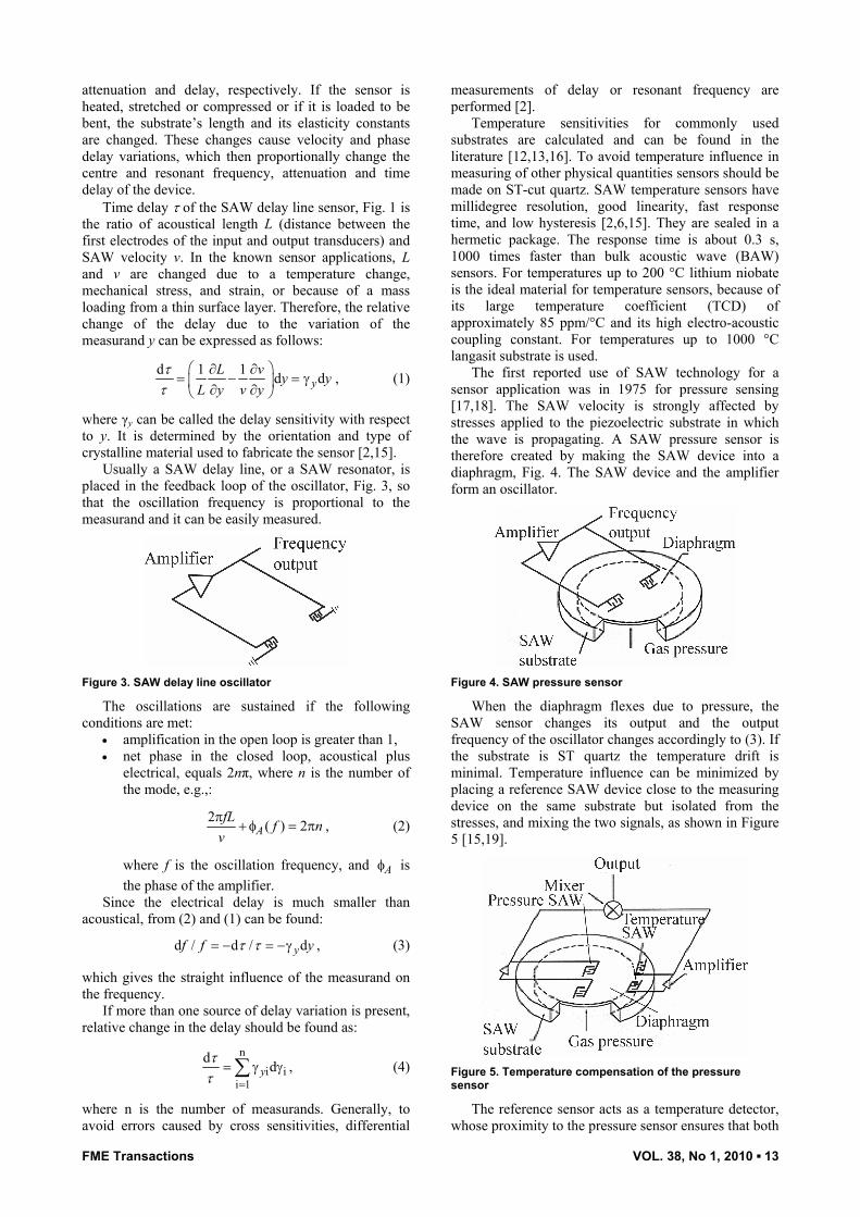
Usually a SAW delay line, or a SAW resonator, is placed in the feedback loop of the oscillator, Fig. 3, so that the oscillation frequency is proportional to the measurand and it can be easily measured.
Figure 3. SAW delay line oscillator
The oscillations are sustained if the following conditions are met:
• amplification in the open loop is greater than 1, • net phase in the closed loop, acoustical plus
electrical, equals 2nπ, where n is the number of the mode, e.g.,:
2 ( ) 2AfL f n
vπ
+ φ = π , (2)
where f is the oscillation frequency, and Aφ is the phase of the amplifier.
Since the electrical delay is much smaller than acoustical, from (2) and (1) can be found:
d / d / dyf f yτ τ= − = −γ , (3)
which gives the straight influence of the measurand on the frequency.
If more than one source of delay variation is present, relative change in the delay should be found as:
n
i ii 1
d dyττ =
= γ γ∑ , (4)
where n is the number of measurands. Generally, to avoid errors caused by cross sensitivities, differential
measurements of delay or resonant frequency are performed [2].
Temperature sensitivities for commonly used substrates are calculated and can be found in the literature [12,13,16]. To avoid temperature influence in measuring of other physical quantities sensors should be made on ST-cut quartz. SAW temperature sensors have millidegree resolution, good linearity, fast response time, and low hysteresis [2,6,15]. They are sealed in a hermetic package. The response time is about 0.3 s, 1000 times faster than bulk acoustic wave (BAW) sensors. For temperatures up to 200 °C lithium niobate is the ideal material for temperature sensors, because of its large temperature coefficient (TCD) of approximately 85 ppm/°C and its high electro-acoustic coupling constant. For temperatures up to 1000 °C langasit substrate is used.
The first reported use of SAW technology for a sensor application was in 1975 for pressure sensing [17,18]. The SAW velocity is strongly affected by stresses applied to the piezoelectric substrate in which the wave is propagating. A SAW pressure sensor is therefore created by making the SAW device into a diaphragm, Fig. 4. The SAW device and the amplifier form an oscillator.
Figure 4. SAW pressure sensor
When the diaphragm flexes due to pressure, the SAW sensor changes its output and the output frequency of the oscillator changes accordingly to (3). If the substrate is ST quartz the temperature drift is minimal. Temperature influence can be minimized by placing a reference SAW device close to the measuring device on the same substrate but isolated from the stresses, and mixing the two signals, as shown in Figure 5 [15,19].
Figure 5. Temperature compensation of the pressure sensor
The reference sensor acts as a temperature detector, whose proximity to the pressure sensor ensures that both
14 ▪ VOL. 38, No 1, 2010 FME Transactions
are exposed to the same temperature. The SAW pressure sensors are passive, rugged, and extremely small and lightweight and can be accessed wirelessly. They are well suited for measuring pressure in car and truck tires [8]. These characteristics offer advantages over technologies such as capacitive and piezo-resistive sensors, which require operating power and are not wireless.
If a SAW device is rigidly mounted to a flat spot on a shaft, and the shaft experiences a torque, this torque will stress the sensor. As the shaft is rotated one way, the SAW torque sensor is placed in tension, and rotated the opposite way, it is placed in compression. For practical applications, two SAW torque sensors are used such that their central lines are at right angles, Fig. 6 [1]. Thus, when one sensor is in compression, the other is in tension. Since both sensors are exposed to the same temperature, the sum of the two signals minimizes any temperature drift effects.
Figure 6. SAW torque sensor
In comparison to other torque sensors, including resistive strain gauges, optical transducers, and torsion bars, SAW torque sensors offer lower cost, lightweight, higher reliability, and wireless operation. Monitoring torque on trucks and cars significantly improves handling and braking because torque measures wheel traction much better than the rpm sensors in current use.
The SAW sensors are the most sensitive to mass loads. This opens up several applications including vapor chemical sensors, biosensors and film thickness sensors. In thickness sensors the thin film is deposited on the substrate between the transducers. In chemical or biosensors the substrate between the transducers is coated with a sensitive substance, which adsorbs or absorbs gas or particles landing on the surface increasing mass loading of the device [19-21].
A mass resolution of 3 pg for a 200 MHz ST-cut quartz SAW has been reported, which was 1000 times the sensitivity of the 10 MHz TSM resonator tested [20]. Particle sensors are used in clean rooms, air quality monitors, and atmospheric monitors.
The measured frequency shift of film thickness sensors is proportional to the mass of the deposited film and can be expressed in the form [21]:
2f f
so
hf f
vρρ
∆ = − , (5)
where ρf and ρs are the densities of the film and substrate, respectively, hf is the thickness of the film and
fo the central frequency of the device. This method is accurate provided that the film is thin (no more than a few percent of the acoustic wavelength). SAW thickness sensors are more sensitive than thickness shear mode (TSM) sensors, which are most commercially available thickness sensors.
3.2 SAW transponders
In the SAW transponders the information about the measurand is gathered by another sensor and it is contained in the impedance ZL, Fig. 1. The voltage across the impedance ZL can be calculated as:
o L oo L
1( ) ( )1
V Z VR Z
= ∞+
, (6)
where Vo (∞) is the output voltage when the output port is open, and Ro is the output resistance of the transducer at centre frequency.
The capacitance of the transducer is usually compensated by an inductance. The resistance Ro is the function of frequency, number of electrodes of the IDT and the type of the substrate.
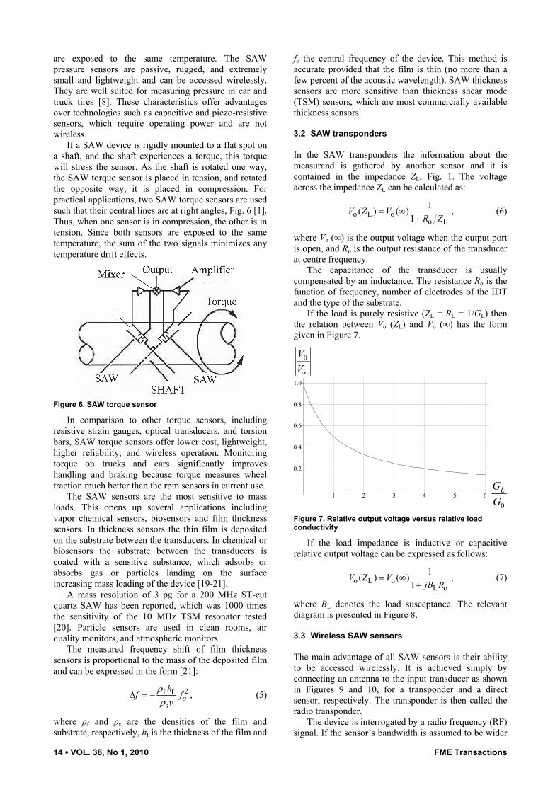
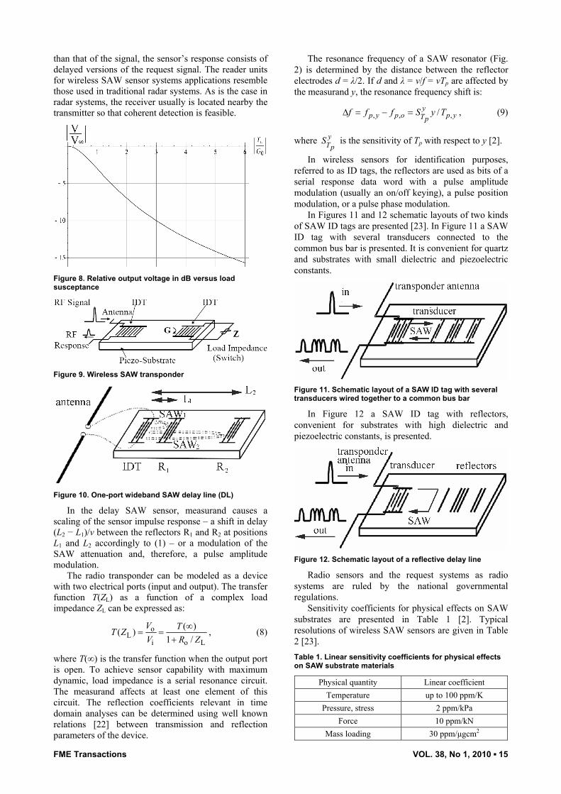
If the load is purely resistive (ZL = RL = 1/GL) then the relation between Vo (ZL) and Vo (∞) has the form given in Figure 7.
1 2 3 4 5 6
Gp
G0
0.2
0.4
0.6
0.8
1.0
TTinf∞VV0
0GGL
Figure 7. Relative output voltage versus relative load conductivity
If the load impedance is inductive or capacitive relative output voltage can be expressed as follows:
o L oL o
1( ) ( )1
V Z VjB R
= ∞+
, (7)
where BL denotes the load susceptance. The relevant diagram is presented in Figure 8.
3.3 Wireless SAW sensors
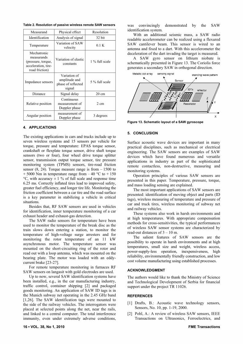
The main advantage of all SAW sensors is their ability to be accessed wirelessly. It is achieved simply by connecting an antenna to the input transducer as shown in Figures 9 and 10, for a transponder and a direct sensor, respectively. The transponder is then called the radio transponder.
The device is interrogated by a radio frequency (RF) signal. If the sensor’s bandwidth is assumed to be wider
FME Transactions VOL. 38, No 1, 2010 ▪ 15
than that of the signal, the sensor’s response consists of delayed versions of the request signal. The reader units for wireless SAW sensor systems applications resemble those used in traditional radar systems. As is the case in radar systems, the receiver usually is located nearby the transmitter so that coherent detection is feasible.
Figure 8. Relative output voltage in dB versus load susceptance
Figure 9. Wireless SAW transponder
Figure 10. One-port wideband SAW delay line (DL)
In the delay SAW sensor, measurand causes a scaling of the sensor impulse response – a shift in delay (L2 − L1)/v between the reflectors R1 and R2 at positions L1 and L2 accordingly to (1) – or a modulation of the SAW attenuation and, therefore, a pulse amplitude modulation.
The radio transponder can be modeled as a device with two electrical ports (input and output). The transfer function T(ZL) as a function of a complex load impedance ZL can be expressed as:
oL
i o L
( )( )1 /
V TT ZV R Z
∞= =
+, (8)
where T(∞) is the transfer function when the output port is open. To achieve sensor capability with maximum dynamic, load impedance is a serial resonance circuit. The measurand affects at least one element of this circuit. The reflection coefficients relevant in time domain analyses can be determined using well known relations [22] between transmission and reflection parameters of the device.
The resonance frequency of a SAW resonator (Fig. 2) is determined by the distance between the reflector electrodes d = λ/2. If d and λ = v/f = vTp are affected by the measurand y, the resonance frequency shift is:
, , ,/yp y p o p yTp
f f f S y T∆ = − = , (9)
where yTp
S is the sensitivity of Tp with respect to y [2].
In wireless sensors for identification purposes, referred to as ID tags, the reflectors are used as bits of a serial response data word with a pulse amplitude modulation (usually an on/off keying), a pulse position modulation, or a pulse phase modulation.
In Figures 11 and 12 schematic layouts of two kinds of SAW ID tags are presented [23]. In Figure 11 a SAW ID tag with several transducers connected to the common bus bar is presented. It is convenient for quartz and substrates with small dielectric and piezoelectric constants.
Figure 11. Schematic layout of a SAW ID tag with several transducers wired together to a common bus bar
In Figure 12 a SAW ID tag with reflectors, convenient for substrates with high dielectric and piezoelectric constants, is presented.
Figure 12. Schematic layout of a reflective delay line
Radio sensors and the request systems as radio systems are ruled by the national governmental regulations.
Sensitivity coefficients for physical effects on SAW substrates are presented in Table 1 [2]. Typical resolutions of wireless SAW sensors are given in Table 2 [23]. Table 1. Linear sensitivity coefficients for physical effects on SAW substrate materials
Physical quantity Linear coefficient Temperature up to 100 ppm/K
Pressure, stress 2 ppm/kPa Force 10 ppm/kN
Mass loading 30 ppm/µgcm2
16 ▪ VOL. 38, No 1, 2010 FME Transactions
Table 2. Resolution of passive wireless remote SAW sensors
Measurand Physical effect Resolution Identification Analysis of signal 32 bit
Temperature Variation of SAW velocity 0.1 K
Mechatronic measurands
(pressure, torque, acceleration, tire-
road friction)
Variation of elastic constants 1 % full scale
Impedance sensors
Variation of amplitude and
phase of reflected signal
5 % full scale
Distance Signal delay 20 cm
Relative position Continuous
measurement of Doppler phase
2 cm
Angular position measurement of Doppler phase 3 degrees
4. APPLICATIONS
The existing applications in cars and trucks include up to seven wireless systems and 15 sensors per vehicle for torque, pressure and temperature: EPAS torque sensor, crankshaft or flexplate torque sensor, drive shaft torque sensors (two or four), four wheel drive torque splitter sensor, transmission output torque sensor, tire pressure monitoring system (TPMS) sensors, tire-road friction sensor (8, 24). Torque measure range is from – 1500 to + 5000 Nm in temperature range from – 40 °C to + 150 °C, with accuracy ± 1 % of full scale and response time 6.25 ms. Correctly inflated tires lead to improved safety, greater fuel efficiency, and longer tire life. Monitoring the friction coefficient between a car tire and the road surface is a key parameter in stabilizing a vehicle in critical situations.
Besides that, RF SAW sensors are used in vehicles for identification, inner temperature monitoring of a car exhaust header and exhaust-gas detection.
The SAW radio sensors for temperature have been used to monitor the temperature of the break disc as the train slows down entering a station, to monitor the temperature of high-voltage surge arresters and for monitoring the rotor temperature of an 11 kW asynchronous motor. The temperature sensor was mounted on the short-circuiting ring of the rotor and read out with a loop antenna, which was mounted on the bearing plate. The motor was loaded with an eddy-current brake [23-27].
For remote temperature monitoring in furnaces RF SAW sensors on langasit with gold electrodes are used.
Up to now, several SAW identification systems have been installed, e.g., in the car manufacturing industry, traffic control, container shipping [2] and packaged goods monitoring. An application of SAW ID tags is in the Munich subway net operating in the 2.45 GHz band [1,26]. The SAW identification tags were mounted to the side of the railway vehicles. The interrogators were placed at selected points along the net, near the rails, and linked to a central computer. The total interference immunity, even under extremely adverse conditions,
was convincingly demonstrated by the SAW identification system.
With an additional seismic mass, a SAW radio readable accelerometer can be realized using a flexured SAW cantilever beam. This sensor is wired to an antenna and fixed to a dart. With this accelerometer the deceleration of the dart invading the target is measured.
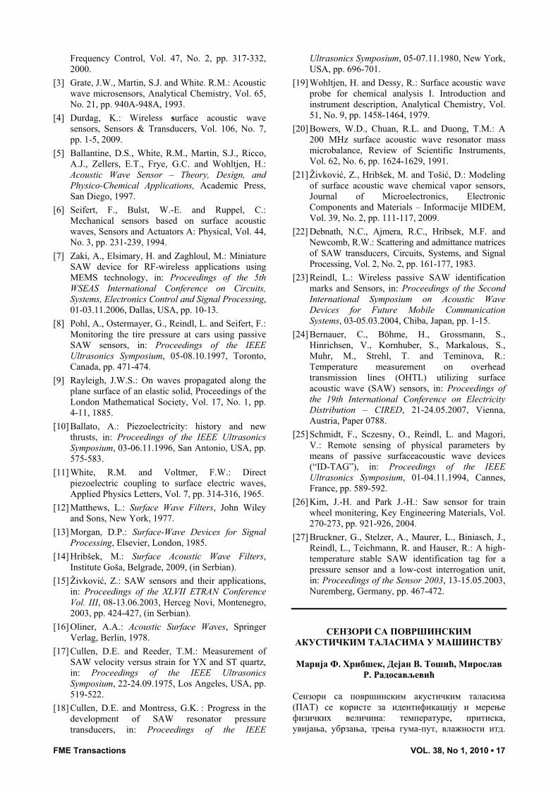
A SAW gyro sensor on lithium niobate is schematically presented in Figure 13. The Coriolis force generates a secondary SAW in orthogonal direction.
Figure 13. Schematic layout of a SAW gyroscope
5. CONCLUSION
Surface acoustic wave devices are important in many practical disciplines, such as mechanical or electrical engineering. The SAW sensors are examples of SAW devices which have found numerous and versatile applications in industry as part of the sophisticated remote contactless, non-destructive, measuring and monitoring systems.
Operation principles of various SAW sensors are presented in this paper. Temperature, pressure, torque, and mass loading sensing are explained.
The most important applications of SAW sensors are presented: identification of moving object and parts (ID tags), wireless measuring of temperature and pressure of car and truck tires, wireless monitoring of subway net and railway vehicles.
These systems also work in harsh environments and at high temperatures. With appropriate compensation methods for cross-sensitivities, the typical performances of wireless SAW sensor systems are characterized by read-out distances of 3 – 10 m.
The salient features of SAW sensors are the possibility to operate in harsh environments and at high temperatures, small size and weight, wireless access, power-supply-less operation, inexpensiveness, high reliability, environmentally friendly construction, and low cost volume manufacturing using established processes.
ACKNOWLEDGMENT
The authors would like to thank the Ministry of Science and Technological Development of Serbia for financial support under the project TR 11026.
REFERENCES
[1] Drafts, B.: Acoustic wave technology sensors, Sensors, No. 10, pp. 1-19, 2000.
[2] Pohl, A.: A review of wireless SAW sensors, IEEE Transactions on Ultrasonics, Ferroelectrics, and
FME Transactions VOL. 38, No 1, 2010 ▪ 17
Frequency Control, Vol. 47, No. 2, pp. 317-332, 2000.
[3] Grate, J.W., Martin, S.J. and White. R.M.: Acoustic wave microsensors, Analytical Chemistry, Vol. 65, No. 21, pp. 940A-948A, 1993.
[4] Durdag, K.: Wireless surface acoustic wave sensors, Sensors & Transducers, Vol. 106, No. 7, pp. 1-5, 2009.
[5] Ballantine, D.S., White, R.M., Martin, S.J., Ricco, A.J., Zellers, E.T., Frye, G.C. and Wohltjen, H.: Acoustic Wave Sensor – Theory, Design, and Physico-Chemical Applications, Academic Press, San Diego, 1997.
[6] Seifert, F., Bulst, W.-E. and Ruppel, C.: Mechanical sensors based on surface acoustic waves, Sensors and Actuators A: Physical, Vol. 44, No. 3, pp. 231-239, 1994.
[7] Zaki, A., Elsimary, H. and Zaghloul, M.: Miniature SAW device for RF-wireless applications using MEMS technology, in: Proceedings of the 5th WSEAS International Conference on Circuits, Systems, Electronics Control and Signal Processing, 01-03.11.2006, Dallas, USA, pp. 10-13.
[8] Pohl, A., Ostermayer, G., Reindl, L. and Seifert, F.: Monitoring the tire pressure at cars using passive SAW sensors, in: Proceedings of the IEEE Ultrasonics Symposium, 05-08.10.1997, Toronto, Canada, pp. 471-474.
[9] Rayleigh, J.W.S.: On waves propagated along the plane surface of an elastic solid, Proceedings of the London Mathematical Society, Vol. 17, No. 1, pp. 4-11, 1885.
[10] Ballato, A.: Piezoelectricity: history and new thrusts, in: Proceedings of the IEEE Ultrasonics Symposium, 03-06.11.1996, San Antonio, USA, pp. 575-583.
[11] White, R.M. and Voltmer, F.W.: Direct piezoelectric coupling to surface electric waves, Applied Physics Letters, Vol. 7, pp. 314-316, 1965.
[12] Matthews, L.: Surface Wave Filters, John Wiley and Sons, New York, 1977.
[13] Morgan, D.P.: Surface-Wave Devices for Signal Processing, Elsevier, London, 1985.
[14] Hribšek, M.: Surface Acoustic Wave Filters, Institute Goša, Belgrade, 2009, (in Serbian).
[15] Živković, Z.: SAW sensors and their applications, in: Proceedings of the XLVII ETRAN Conference Vol. III, 08-13.06.2003, Herceg Novi, Montenegro, 2003, pp. 424-427, (in Serbian).
[16] Oliner, A.A.: Acoustic Surface Waves, Springer Verlag, Berlin, 1978.
[17] Cullen, D.E. and Reeder, T.M.: Measurement of SAW velocity versus strain for YX and ST quartz, in: Proceedings of the IEEE Ultrasonics Symposium, 22-24.09.1975, Los Angeles, USA, pp. 519-522.
[18] Cullen, D.E. and Montress, G.K. : Progress in the development of SAW resonator pressure transducers, in: Proceedings of the IEEE
Ultrasonics Symposium, 05-07.11.1980, New York, USA, pp. 696-701.
[19] Wohltjen, H. and Dessy, R.: Surface acoustic wave probe for chemical analysis I. Introduction and instrument description, Analytical Chemistry, Vol. 51, No. 9, pp. 1458-1464, 1979.
[20] Bowers, W.D., Chuan, R.L. and Duong, T.M.: A 200 MHz surface acoustic wave resonator mass microbalance, Review of Scientific Instruments, Vol. 62, No. 6, pp. 1624-1629, 1991.
[21] Živković, Z., Hribšek, M. and Tošić, D.: Modeling of surface acoustic wave chemical vapor sensors, Journal of Microelectronics, Electronic Components and Materials – Informacije MIDEM, Vol. 39, No. 2, pp. 111-117, 2009.
[22] Debnath, N.C., Ajmera, R.C., Hribsek, M.F. and Newcomb, R.W.: Scattering and admittance matrices of SAW transducers, Circuits, Systems, and Signal Processing, Vol. 2, No. 2, pp. 161-177, 1983.
[23] Reindl, L.: Wireless passive SAW identification marks and Sensors, in: Proceedings of the Second International Symposium on Acoustic Wave Devices for Future Mobile Communication Systems, 03-05.03.2004, Chiba, Japan, pp. 1-15.
[24] Bernauer, C., Böhme, H., Grossmann, S., Hinrichsen, V., Kornhuber, S., Markalous, S., Muhr, M., Strehl, T. and Teminova, R.: Temperature measurement on overhead transmission lines (OHTL) utilizing surface acoustic wave (SAW) sensors, in: Proceedings of the 19th International Conference on Electricity Distribution – CIRED, 21-24.05.2007, Vienna, Austria, Paper 0788.
[25] Schmidt, F., Sczesny, O., Reindl, L. and Magori, V.: Remote sensing of physical parameters by means of passive surfaceacoustic wave devices (“ID-TAG”), in: Proceedings of the IEEE Ultrasonics Symposium, 01-04.11.1994, Cannes, France, pp. 589-592.
[26] Kim, J.-H. and Park J.-H.: Saw sensor for train wheel monitering, Key Engineering Materials, Vol. 270-273, pp. 921-926, 2004.
[27] Bruckner, G., Stelzer, A., Maurer, L., Biniasch, J., Reindl, L., Teichmann, R. and Hauser, R.: A high-temperature stable SAW identification tag for a pressure sensor and a low-cost interrogation unit, in: Proceedings of the Sensor 2003, 13-15.05.2003, Nuremberg, Germany, pp. 467-472.
СЕНЗОРИ СА ПОВРШИНСКИМ
АКУСТИЧКИМ ТАЛАСИМА У МАШИНСТВУ Марија Ф. Хрибшек, Дејан В. Тошић, Мирослав
Р. Радосављевић Сензори са површинским акустичким таласима (ПАТ) се користе за идентификацију и мерење физичких величина: температуре, притиска, увијања, убрзања, трења гума-пут, влажности итд.

18 ▪ VOL. 38, No 1, 2010 FME Transactions
Сензори не захтевају посебан извор за напајање. Може им се приступити бежичним путем што омогућава њихову употребу на опасним и тешко доступним местима у затвореном или отвореном
простору. Објашњени су принципи рада, анализа и врсте ПАТ сензора. Приказано је неколико примера бежичних мерења у аутомобилима и шинским возилима.