surf tm: a surface synthesizer for architectural...
TRANSCRIPT

�
11
SURF_TM: A SURFACE SYNTHESIZER FOR
ARCHITECTURAL FORMS
June-Hao Hou Graduate Institute of Architecture
National Chiao Tung University 1001 Ta Hsueh Road
Hsinchu City 300.Taiwan
Abstract
Parametric equation is one of the possible ways to generate free-form architecture in modern age. When
working with mathematical software, designers need a way to bring surface mesh to CAD for further design.
Surf_TM is an supplemental tool for AutoCAD to import and manipulate surface mesh data from Mathcad.
Accompanying with a course taught in Harvard Design School, students gain knowledge in mathematics and
use parametric equation as a design tool. This paper elaborates details of the course, the tool, how they work
together, and example applications.
1. Introduction
In architectural graduate school, usually mathematics would be taught in engineering and computer-related
courses such as civil engineering, structural analysis, and Geographic Information System (GIS). Nevertheless, it is used virtually everywhere in architectural design, from drafting to shop drawing, and from area
calculation to budget estimation. Historically, architecture has intimate relationship with mathematics and is
indistinguishable from each other. In ancient Greece and Rome, architects were even required to be
mathematicians (Salingaros, 1999).
Mathematical principles rule architecture forms since very early in human history. Although it is arguable
when was the exact period, there is no doubt that mathematics is more than crucial to architecture design and
construction. From daily design practices to constructions and project management, all parties in an
architecture project live by numbers. For instance, project managers keep track of project schedule, prepare
budget fees for clients, and verify the quantity of building materials. For civil engineers, mathematics plays an
even more critical role in their career. One might be curious about that, except for those jobs grounded on
science and engineering, does an architect require mathematics beyond making scale drawings, designing by
measurements and strength of materials, and arranging orders by proportion and numbers?
Architects imagine, design, and realize architecture forms. There are various means to come up the initial
forms during schematic design–by sketching, drawing, playing with chipboard models, or inspiring from natural forms. New media and technology have brought up new ways to design forms (Mitchell et al., 1995).
After schematic design, ideas are brought into computer-aided design (CAD) program by manual modeling,
laser scanning, digitizing, or other reverse engineering methods. Interestingly, today most buildings are still
designed by simple geometric solids, so called fundamentalism (Mehaffy et al., 2002), despite new
technology has enabled us to build complex geometry up to the building’s scale. Depart from classic, if not
mundane, orders and geometries, pioneering architects such as Frank Gehry and Zaha Hadid start to think out
of the box and escape from simple geometries and explicit orders (Dal Co et al., 2003).

�
12
Figure 1. Peter B. Lewis Building at Case Western Reserve University, Cleveland, USA. Designed by Frank O. Gehry.
-
Figure 2. Guggenheim Museum, Taichung, Taiwan. Designed by Zaha Hadid.
Free-form technology is one of the tools for contemporary architects to embody their creative ideas. It has
become one of the emerging design methods been adopted by leading firms and schools. One of the trends in modern architecture design is algorithmic architecture, which uses algorithm (or rules) to generate
architecture forms. It relies on computer programs, ranging from rule-based reasoning, artificial intelligence
to genetic algorithm, to produce forms or structures without too much human interventions. Architect Makoto
Watanabe has used this design method in various projects, e.g. the design of Iidabashi station of subway Oedo
line in Tokyo (Watanabe, 2002). Another common approach to design free-form is by freehand sculpting the
surface, either in CAD or by digital clay. It does not require programming and mathematics. Architects are
free to make any form in their mind. Simply said, there is no limitation to the form, as long as it can be built.
Total freedom in architecture form is a break through of how we design and understand architecture as we
finally break the limitation set by ruler and compass.
Mathematical form is one of the most elegant things invented (or discovered) by human being. It is also is
also a source of creativity. It demonstrates not only the beauty and sophistication of equation, algorithm,
relationship of numbers, and tendency, to some extent it inspires designers by its appearance, how it is
structured, and linkage to the natural forms. Architecture forms derived from mathematical forms inherit the
beauty of implicit order and intrinsic patterns that is hard to be replicated by freehand modeling. Architects
mimic forms from nature. In Sagrada Familia, Antonio Gaudi used hyperboloid in the columns and conoid in the roof of the Provisional Schools. And he used helicoids in the columns of the Teresian School. “Gaudi’s
compositions are inspired by nature, they stand out from those of architects who have always utilized a simple
geometry based on abstract form...(Nonell, 2001)” Architect Greg Lynn has been using animation and
biological forms to derive architectural design (Lynn, 1998). Later he works on embryological forms and
organic intricacy, which brings architecture to life and to microscopic sophistication.

�
13
Recently, parametric design has gradually become mainstream in CAD industry and architectural design will
eventually be parameterized to certain extent. Working with parameters is actually working with relationships of design entities. Ideally, parametric architectural software would capture conceptual design intent and
maintain entity relationships and possible solutions throughout design development (Rotheroe, 2002). As
parametric design becoming more important, architects are seeking more knowledge to consolidate their
understanding of parametric design. Practicing with mathematical equations and apply to real world problems
become the best way to do so.
In this paper, we will briefly introduce the specific course taught in Harvard University in section 2, and then
explain how Surf_TM works in multi-application environment to support the course in section 3. Surf_TM is
suggested to be an example of bridging technology in architecture practices and education, which depend
largely on existing tools. In section 4, possible applications of Surf_TM environment will be suggested.
Finally, in section 5, we will conclude and discuss limitations and future developments of Surf_TM.
2. The Course: Superficial Spaces
To help students understanding orders and mathematical rules of organic forms and free-form, at Harvard Graduate School of Design (GSD) the course GSD7303 On Growth and Form 2.0, named after D’Arcy
Thompson’s canon in biological forms and mathematics (Thompson, 1992), was set up in the Spring of 1997,
taught by George Liaropoulos-Legendre. Thompson’s essays were source of discussions followed by
practices on geometric transformation and parametric surface generation. In this course students re-learned
parametric equations, coordinate transformation, matrix, and surface mesh. They were asked to experiment
parametric surfaces in mathematical software, then bring the generated data to CAD for further processing
and prototype modeling.
Mathcad is used to generate surface mesh and AutoLISP was for studying surfaces, and manipulating the
vertices, warp and weft of the mesh. Topics of computer graphics such as Bezier curve and projections were
taught so students can handle geometries with ease. The final project was to develop an in-depth analysis and
visualization of a special form or use the parametric surface in a design problem. The course became
GSD7303 Superficial Spaces in Spring 2002 to reflect the change of focus from Thompson’s book to
Liaropoulos-Legendre’s essays (Liaropoulos-Legendre, 2003) which were written from the perspective of an
architect and educator in design school.
2.1 Curriculum
This course was specifically designed for architecture students having interests in using mathematical forms
in their designs, researching manufacturability of the framework of a complex shape, and looking for
relationships between mathematics and architectural forms. Students taking this course are supposed to have
basic computer knowledge and proficiency in CAD software. Although programming experience is not
required, students should be willing to do so and actively explore the realm of mathematics. Furthermore, the
course will take students from immaterial mathematical notation to materialized models by large-format
printing, CNC machines, laser cutting, and rapid prototyping techniques.
By large-format printing, the challenge is to layout equations, surface plots, line drawings, rendering, data
points and text into an meaningful interpretation of a surface in question. And students are encouraged to
develop new ways to visualize as much characteristics as possible of a surface on a 2D printing. By laser
cutting, a surface model could be sliced into a set of construction frames which could be assembled as a
framework. Since the direction of slicing and material are up to one’s choice, the outcome usually fascinate
the audience. And by rapid prototyping, any kind of surface with thickness can be printed into a volumetric model for quick preview and studies using 3D printing machine, though it is greatly limited by the cost of
printing material and printable size–usually within 10 cubic in. After done with this course, except for dialects
of surface properties in architectural form and understanding of parameters, students should gain knowledge
and hands on experience in experimenting and making mathematical forms.

�
14
2.2 Class Schedule
-
Lectures on mathematics and surface issues are arranged every other weeks, along with tutorials specifically
for the AutoLISP language. The other half of the course is focused on workshops in Mathcad, AutoCAD, and
computer-aided manufacturing (CAM) techniques. The following course schedule is based on Superficial
Spaces, Spring 2002, at GSD.
-
Table 1. Class Schedule of Superficial Spaces 2002
Week 1 Lecture: Superficial Spaces
Week 2 Workshop: Introductory Applications
Mathcad ranges, equations, and graphs. Review of basic mathematical concepts.
AutoLISP in AutoCAD. AutoLISP Command Line Interface. Guide to learning resources.
Week 3 Lecture: I Love Matrices
Tutorial: AutoLISP Function Design. Point and List-Oriented Functions.
Week 4 Workshop: Intermediate Applications
Mathcad functions, parametric plots and animated graphs. Review of basic math concepts.
The AutoLISP Integrated Development Interface (IDE). Work flow and debugging.
Week 5 Lecture: Variable Lines
LISP Tutorial: Decisions, queries and alternatives. Loops and iterations.
Week 6 Workshop: Advanced Applications I
Modeling with Mathcad and AutoLISP. AutoCAD surface models. The Surf_TM
Environment.
Week 7 Lecture: The Numerical Weave
LISP Tutorial: More loops and iterations. Integrating numeric typography.
Week 8 Workshop: Material Prints and Cuts
Large-size printing: paper size/format, preparing the file, and file conversion.
Surface Laser-cutting: file format, file preparation, file conversion.
Week 9 Mid-term Presentation
Week 10 Workshop: Advanced Applications II
Advanced Entity Data in AutoLISP. General principles. Coordinate Transformations in AutoLISP.
Week 11 Lecture: Linearity, Periodicity, Symmetry and Transposition
LISP Tutorial: Advanced entity data. Applied examples.
Week 12 Workshop: Advanced Applications II
Iteration applied to surface modeling in AutoLISP. Polygon arrays.
Manual list processing. Slope and curvature modeling in AutoLISP.
Week 13 Lecture: Curvature
AutoLISP Q&A and Problem Solving
Week 14 Final Presentation
-
In the first half of the course, students are encouraged to explore and experiment as much as they could. The
purpose is to help students realizing how mathematical principles work and what affects the outcome
(surface). In the mid-term presentation, students should demonstrate the ability to interpret and dissect the
surface mesh of interest. The second half of the course will move to a somewhat reverse direction, Students
practice how to compose the surface in different ways – mathematically, programmatically, and analytically.
At the end of the course, students should be able to model a surface in their mind by the knowledge and tools
they learned in the class.
�
15
3. The Tool: Surf_TM
Surf_TM was originally designed by Liaropoulos-Legendre in 1996 on AutoCAD R13 in support of the course On Growth and Form 2.0. It laid out the basic blueprint which is unchanged till the latest version.
Being a student in this class in 1999, the author suggested a much simpler and efficient data structure, a new
graphic user interface, and has done a major revision to the environment. Since then the author has become
the main developer of this environment.
Mathcad was used as an experimental environment so students can quickly preview surface when testing
parameters and equations. The generated matrix data were then output to text files in generic format. To bring
data into AutoCAD, Surf_TM is used to handle data import, data conversion (to/from AutoCAD entities),
mesh editing/parsing/composing, and user interactions. After the matrix data been loaded, students are able to
do analysis and manipulations to the surface.
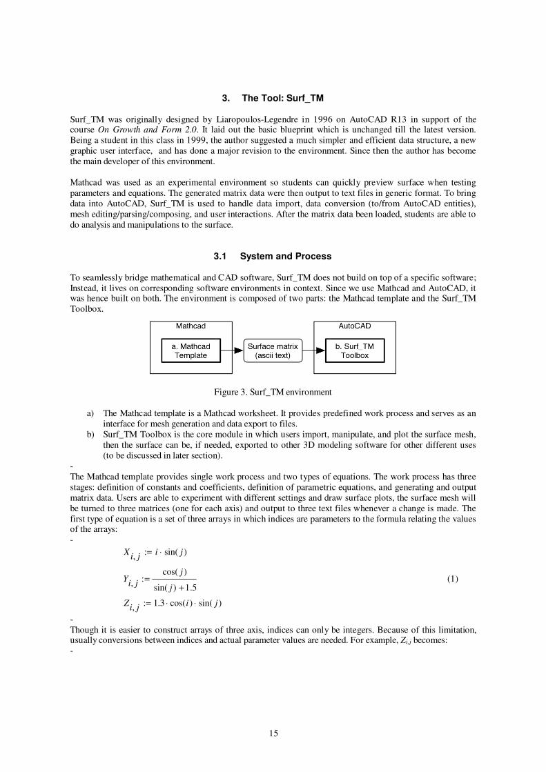
3.1 System and Process
To seamlessly bridge mathematical and CAD software, Surf_TM does not build on top of a specific software;
Instead, it lives on corresponding software environments in context. Since we use Mathcad and AutoCAD, it was hence built on both. The environment is composed of two parts: the Mathcad template and the Surf_TM
Toolbox.
Figure 3. Surf_TM environment
a) The Mathcad template is a Mathcad worksheet. It provides predefined work process and serves as an
interface for mesh generation and data export to files.
b) Surf_TM Toolbox is the core module in which users import, manipulate, and plot the surface mesh,
then the surface can be, if needed, exported to other 3D modeling software for other different uses
(to be discussed in later section).
-
The Mathcad template provides single work process and two types of equations. The work process has three
stages: definition of constants and coefficients, definition of parametric equations, and generating and output
matrix data. Users are able to experiment with different settings and draw surface plots, the surface mesh will
be turned to three matrices (one for each axis) and output to three text files whenever a change is made. The
first type of equation is a set of three arrays in which indices are parameters to the formula relating the values of the arrays:
-
Xi, j
:= i ⋅ sin( j )
Yi, j
:=cos( j )
sin( j ) +1.5
Zi, j
:= 1.3 ⋅ cos(i ) ⋅ sin( j )
(1)
-
Though it is easier to construct arrays of three axis, indices can only be integers. Because of this limitation, usually conversions between indices and actual parameter values are needed. For example, Zi,j becomes:
-

�
16
step :=
π
20, offset :=
3
4π
Zi, j := 1.3 ⋅ cos(i ⋅ step + offset) ⋅ sin( j ⋅ step + offset)
(2)
-
By this way, one is able to precisely control the range and the density of grids of the mesh – they are all
parameterized. The second type of equation is a three-element vector-valued function of two variables.
-
P (x, y) :=
x ⋅ sin(y)
cos(y)
sin(x) + 1.5
1.3 ⋅ cos(x) ⋅ sin(y)
N := CreateMesh(P,0, 2π ,−π ,π ,40, 40)
(3)
-
Using CreateMesh() function in Mathcad, one may control ranges and mesh density much easier than in
equation (2). We provide both in the template for students to understand that there are two alternative ways to
write and control their equations.
-
The Surf_TM Toolbox is written in AutoLISP and take advantage of what AutoCAD has provided in entity drawing and management. It is capable of:
-
• Loading three text files generated by Mathcad and reorganize them into a master point list.
• Converting a native AutoCAD 3D mesh into a master point list.
• Retrieving threads in warp and weft direction from a mesh (i.e. the master point list).
• Labeling a point on the mesh. -
Since we do not intend to substitute what AutoCAD can do with geometries, Surf_TM is merely a plug-in for
AutoCAD with supplemental functionalities. The overall workflow of Mathcad and Surf_TM Toolbox is
illustrated in Figure 4.
-
Figure 4. Surf_TM workflow
-
Surfaces regenerated in AutoCAD can, of course, be exported to other CAD program for further process, such
as making animation, photorealistic rendering, laser cutting, CNC, 3D printing,...etc. Combining with
Surf_TM environment, manufacturing of a mathematical forms becomes a straight forward process and is

�
17
much more efficient than before. In the following paragraphs, we will further elaborate Surf_TM’s roles in
various situations.
3.2 A Bridging Tool
As mentioned above, Surf_TM environment was designed to bridge Mathcad and AutoCAD. Surface meshes
generated in Mathcad can be exported and saved in text format. Then the mesh data were imported into
AutoCAD by Surf_TM for further processing. Users, of course, can perform mathematical experiments in
Mathcad and bring surface meshes into AutoCAD without Surf_TM’s help. However, without this tool, users
must know how to program and customize CAD software in order to accomplish the job, which is time
consuming and impractical to most architecture firms and schools. Some firms, such as Frank O. Gehry’s,
may have specialized programmers or architects who are capable of programming to develop their own tools,
but it is potentially a steep learning curve for most designers. Surf_TM does this job by importing mesh data
and stitch them into a master point list. This point list becomes the source date for regenerating mesh and
retrieving thread lines in AutoCAD.
Figure 5. Bringing surface mesh from Mathcad to AutoCAD
This tool demonstrate a streamlined workflow specifically designed for architects (or designers in general).
Therefore they can spend most efforts in experimenting the equations and relationships of parameters without
worrying how to transfer the surface mesh to their favorite CAD program.
3.3 An Environment for Experiment
Mathematical software is by nature a perfect environment for experiments on different aspects of a
mathematical issues. One can play with different values of a parameter, modify equations, test the range,
rotate and examine the surface plots. One powerful feature of Mathcad is to make animations based on a
global variable FRAME, and users are free to place this variable anywhere in the equation. By making
animation, we are able to see more details that is hard to be examine as a whole, and to visualize how one
value can affect the form.
Surf_TM enables experiments by its capable of loading native AutoCAD entity such as 3dmesh and 3dpoly
into the master point list. So users can alter the surface and curves, including their smoothness, type of curve,
and transformation before analyze them. Even for those of meshes which are not generated by Mathcad,
Surf_TM can analyze them without any problem. This really means that an user can do iterative experiments
in both Mathcad and AutoCAD.
�
18
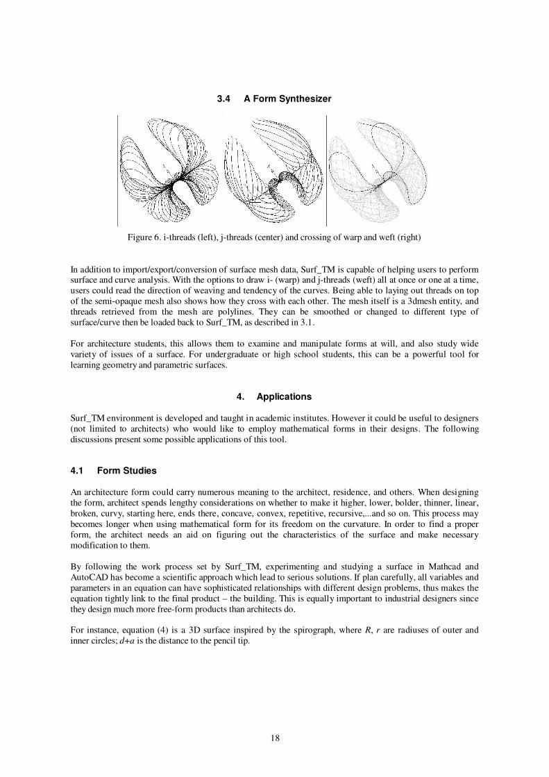
3.4 A Form Synthesizer
Figure 6. i-threads (left), j-threads (center) and crossing of warp and weft (right)
In addition to import/export/conversion of surface mesh data, Surf_TM is capable of helping users to perform surface and curve analysis. With the options to draw i- (warp) and j-threads (weft) all at once or one at a time,
users could read the direction of weaving and tendency of the curves. Being able to laying out threads on top
of the semi-opaque mesh also shows how they cross with each other. The mesh itself is a 3dmesh entity, and
threads retrieved from the mesh are polylines. They can be smoothed or changed to different type of
surface/curve then be loaded back to Surf_TM, as described in 3.1.
For architecture students, this allows them to examine and manipulate forms at will, and also study wide
variety of issues of a surface. For undergraduate or high school students, this can be a powerful tool for
learning geometry and parametric surfaces.
4. Applications
Surf_TM environment is developed and taught in academic institutes. However it could be useful to designers
(not limited to architects) who would like to employ mathematical forms in their designs. The following
discussions present some possible applications of this tool.
4.1 Form Studies
An architecture form could carry numerous meaning to the architect, residence, and others. When designing
the form, architect spends lengthy considerations on whether to make it higher, lower, bolder, thinner, linear,
broken, curvy, starting here, ends there, concave, convex, repetitive, recursive,...and so on. This process may
becomes longer when using mathematical form for its freedom on the curvature. In order to find a proper
form, the architect needs an aid on figuring out the characteristics of the surface and make necessary
modification to them.
By following the work process set by Surf_TM, experimenting and studying a surface in Mathcad and
AutoCAD has become a scientific approach which lead to serious solutions. If plan carefully, all variables and
parameters in an equation can have sophisticated relationships with different design problems, thus makes the
equation tightly link to the final product – the building. This is equally important to industrial designers since
they design much more free-form products than architects do.
For instance, equation (4) is a 3D surface inspired by the spirograph, where R, r are radiuses of outer and
inner circles; d+a is the distance to the pencil tip.

�
19
R := 20, r := 10, k := 2.5, d := 2
G(t,a) :=
(R + f ⋅ r) ⋅ cos(t ⋅f
k) + (d + a) ⋅ cos(t +
a
16)
(R + f ⋅ r) ⋅sin(t ⋅f
k) + (d + a) ⋅sin(t +
a
16)
2 ⋅sin(t ⋅6
k) ⋅sin(a ⋅ π
8)
(4)
In Figure 6, we demonstrate eight clips from the image sequence of equation (4), where f is moving from 0 to
–3 (from left to right, top to bottom).
Figure 7. Animation shows how changes of f affects the form
What exactly the coefficient f does to the surface form is worthwhile for in-depth research since it affect the
graph dramatically. Such study are valuable to the understanding of the equation and overall appearance of its
graph.
4.2 Fabrication and Rapid Prototyping
Fabrication of a mathematical form is by itself an exciting experience as we have rarely seen and touched the
product of an equation. With data of the surface mesh in hand, we could quickly build the digital model and
test its appearance, color, materials, and shadow before it is used in an architecture design. This is the digital
representation of the surface. But seeing meshes on screen is one thing, making it a physical model is another
– because of the thickness issue. Giving thickness to a surface is a strategic and tricky decision, it varies from way of fabrication to another.
Figure 8. Unfolded triangulated mesh for laser cutting

�
20
For instance, to laser cut a surface mesh, we need to make sure every facet (or polygon) is coplanar – which is
done by triangulation. However, the triangulated surface somewhat lost the sense of curvature and its smoothness. Another way to do so is to analyze the surface and make sure it can be made by sheet materials,
just like Frank Gehry did on his projects. This may requires specialized software and some compromises
between manufacturability and precision.
Figure 9. Parametric 3D spirographic forms, by June-Hao Hou
Rapid prototyping technology, including lithographic printing and CNC router, enables quick previewing and
studying of the physical model of a digital form – to make virtual matters real.
4.3 Source of Design Derivation
Three Steps and a Shelf was a project completed at the AA School of Architecture in 2002. It explores the
adaptability of parametric design and the surface’s capacity to take up programmatic demands. Tools been
used are Mathcad, Surf_TM environment, AutoCAD, and Rhinoceros NURBS modeler.
-
Figure 10. Project Three Steps and a Shelf was made of several curve segments
There are many interesting notes during the development of design. As described in ijp: the Book of Surfaces (Liaropoulos-Legendre, 2003) of how it was done:

�
21
...sprung into three stages. First came the techno-conceptual task of defining the form of the curve. In a remarkable act of lateral thinking, the curve emerged through the deliberate misuse
of the parametric equations of a surface. ... The team chose to increase the flexibility of their
surface-curve through a piecemeal approach that strung together several independent pieces to
form a single, continuous whole.
...Then came the stage of dimensional tuning and programming. ...in relation to the scale of the
room and that of the human body. ...they opted for control-point geometry and its attendant
properties as the medium of choice.
...Finally came the stage of physical fabrication. ...using 523 horizontally stacked profiles to
better approximate the profile of the new corner.
This project has shown flexible roles of mathematical form in a design. Designers did not use the form as a
whole, instead they treat it as a raw material. The form can be used partially, as one entity, or can derive other
forms. Unlike algorithmic design which might dominate large portion of a design (because of its iterative
generation), mathematical forms are served as source of derivation. Mathematical principles are there, designers choose which one to use natually. It can be explicitly visible, it can be used in an intrinsic manner.
An important concept in this project is: mathematical forms are subject to adapt to other factors. It doesn’t
need to take over the stage.
5. Conclusion
Surf_TM is an important addition to current CAD system. It provides a fluent process in cross-disciplinary
applications that architects (and designers) may love to deploy in design projects. It also points out the
inability when working in such environment if one is not capable of programming. Surf_TM offers a set of
tools and a interface that is as easy as in ordinary CAD program.
Allowing architectural students and researchers to experiment in mathematical software and exchange
information with their favorite CAD tools is one of the major advantages of Surf_TM. It not only bridges the
gaps, also shows examples of using mathematics as a powerful design tool. From the result and experiences in
teaching this course and using Surf_TM, students were found to be able to build up understandings of the relationship of mathematics and modern architectural design, mapping design factors to and from parameters,
and bringing parametric surfaces from equations to CAD/CAM and to physical prototypes.
Current version of Surf_TM Toolbox only runs on AutoCAD, users have to use AutoCAD as a converter to
import and convert it to a generic format if they want to work in other CAD programs. However, it would be
better to be able to load data in commonly used CADs, such as Rhinoseros, Maya, and 3D Studio Max, and
store in their native entity format. The other possible advance would be to allow entering parametric equations
directly in Surf_TM Toolbox if an user already has idea in mind. Thus Mathcad still works as a laboratory,
and Surf_TM getting complete in its functionality.
Although Surf_TM was developed to support its sibling course, it can be used in different settings such as
architecture studio, design practices, and in many circumstances. This paper can be a useful reference for
architecture institutions and individuals who wants to have formal free-form design method, to develop their
own bridging tools, or to simply teach mathematics to architecture students.
Liaropoulos-Legendre and the author have been taking and extending the course and the tool with them after teaching in GSD. Except for being a teaching faculty in AA, Liaropoulos-Legendre has taught this course in
Princeton University and lectures in other schools. He has being active in new media researches and has
advised projects in MIT Media Lab and Department of Architecture of Swiss Federal Institute of Technology,
Zurich (ETH). Recently one of his art works derived from his book was accepted to a renowned contemporary
art exhibition Prague Biennale 1 2003, as part of the project Aión: An Eventual Architecture (Di Stefano,

�
22
2003). The author teaches a similar course Weaving Parametric Surfaces at the Graduate Institute of
Architecture in National Chiao Tung University, Hsinchu, Taiwan, which is one of the architecture programs dedicated to digital and free-form architecture.
References
Dal Co, F. and F. Dal Co (2003). Frank O. Gehry: The Complete Works, Phaidon Press Inc.
Di Stefano, A. (2003). Aión: An Eventual Architecture [Web page]. Prague Biennale 1 2003. Available from
http://www.praguebiennale.org/projects/aion_distefano.asp.
Liaropoulos-Legendre, G. (2003). ijp: The Book of Surfaces. London, Architectural Association.
Lynn, G. (1998). Animate Form, Princeton Architectural Press.
Mehaffy, M. W. and N. A. Salingaros (2002). "Geometrical Fundamentalism." Plan Net Online Architecture
Resources.
Mitchell, W. J. and M. McCullough (1995). Digital Design Media, Van Nostrand Reinhold.
Nonell, J. B. (2001). Antonio Gaudi, Master Architect, Abbeville Press, Inc.
Rotheroe, K. (2002). A Vision for Parametric Design. Architecture Week.
Salingaros, N. A. (1999). "Architecture, Patterns, and Mathematics." Nexus Network Journal 1: 75-85. Thompson, D. A. W. (1992). On Growth and Form: The Complete Revised Edition, Dover Publications.
Watanabe, M. S. (2002). The Induction Cities, Birkhauser.