sure-flex elastomeric couplings...
TRANSCRIPT

A L T R A I N D U S T R I A L M O T I O N
Sure-Flex®
Elastomeric Couplings (Metric)

2 TB Wood’s 888-829-6637 .....P-1957-TBW-A4 11/12
Sure-Flex couplings utilize a rubber (EPDM or Neoprene) or Hytrel™ thermoplastic flex element (sleeve) to transmit torque and accommodate shaft misalignments. Sure-Flex couplings have exceptional torsional flexibility, and the 4-way flexing action absorbs virtually all types of shock, vibration, misalignment, and end float. Sure-Flex couplings are an excellent choice when low cost, high flexibility, vibration damping, and easy installation are primary concerns.
Sure-Flex couplings last 2X to 30X longer“Fatigue Test To Failure” results revealed that Sure-Flex coupling polymeric flex elements lasted twice as long as the nearest competitive coupling and up to 30 times longer than the remaining competitive models.
Sure-Flex® couplings are a TB Wood’s original!
Sure-Flex couplings can be found hard at work in many industries such as power generation and material handling. These couplings are ideal for a wide variety of applications including:
• Pumps• Fans/Blowers• Compressors• Mixers• Electric Motors• Conveyors
Applications
• Up to 8.20 kNm; 72,480 in.lbs.
• Quick and easy installation
• Spacer, bushed hub, and clamping hub designs in stock
• Flexible design accommodates misalignment and protects equipment
• 7 to 15 degree torsional wind-up
• Needs no lubrication, no maintenance
Features (Metric)Need hi-res color fileEasy, Quick Installation
Sure-Flex can be installed quickly and easily, because there are no bolts, gaskets, covers or seals. Alignment can be checked with a straightedge placed across the outside of the precision-machined flanges. No special tools are needed for installation, alignment or removal.
No Lubrication, Trouble-Free OperationThe teeth of the sleeve lock into the teeth of the flanges without clamps or screws, tightening under torque to provide smooth transmission of power. There is no rubbing action of metal against rubber to cause wear. Couplings are not affected by abrasives, dirt, or moisture. This eliminates the need for lubrication or maintenance, provides clean, dependable, quiet performance.

3P-1957-TBW-A4 11/12.... TB Wood’s 888-829-6637
Sure-Flex Selection Guide
Sure-Flex 4-Way flexing action absorbs all types of shock, vibration and misalignment
Table of Contents
AxialSure-Flex couplings may be used in applications with limited axial shaft movements. The axial com-pressibility of the EPDM and Neoprene sleeves allows for shaft end-float without the absolute transfer of thrust loads.
ParallelParallel misalignment is absorbed without wear or ap-preciable energy losses. The lateral flexibility of the coupling sleeve minimizes radial bearing loads nor-mally asso ciated with parallel misalignment. This fea-ture also allows for easier installation by the use of components bored for slip fits without fretting corro-sion occurring at the shaft. Refer to page 17 for parallel misalignment limits. Only a straight-edge and feeler gage are required to obtain these limits.
AngularThe unique design of the Sure-Flex coupling’s teeth allows for the absorption of angular misalignment without wear. Refer to page 17 for actual allowable misalignment limits. These limits allow for the align-ment of the coupling using only a scale and calipers.
TorsionalSure-Flex coupling sleeves have an exceptional abil-ity to absorb torsional shock and dampen torsional vibrations. The EPDM and Neoprene sleeves wind-up approxi mately 15° torsionally at their rated torque. Hytrel sleeves will wind-up about 7°.
Selection Guide 3-7
Components 3
Sleeve Selection 4
Assembly Dimensions 5
Load/Service Factor 6
Coupling Ratings 7
Type S Sure-Flex 8-9
Type J Sure-Flex 10
Type B Sure-Flex 11
Type SC Sure-Flex 12–15
Type C Sure-Flex 16
Installation Instructions 17
Sure-Flex couplings are selected as component parts.
1. Determine SLEEVE material and type. Refer to pages 4 & 5
2. Determine coupling SIZE. Refer to pages 6 & 7
3. Determine FLANGES to be used. Refer to pages 8 thru 16
Specify coupling components.
• Example #1 - Close coupled Size 6, Type S flange w 35 mm bore Size 6, Type S flange w 25 mm bore Size 6, Solid EPDM sleeve
• Example #2 - 5” Between shaft spacer Size 9, Type SC flange for #11 hub Size 9, Type SC flange for #9 hub Size 11 hub w 2-3/8” bore Size 9 short hub w 1-1/8” bore Size 9 Solid Hytrel sleeve
Metric Version Catalog
For Imperial information see Catalog P-1690-TBW
Prod. Number Prod. Description
S35 mm 6S x 35 mm
6S25 mm 6S x 25 mm
6J9SC5011
6JE9SC50-11
9SC50 9SC50
11SCH238 11SCH x 2-3/8
9SCHS1189H
9SCHS x 1-1/89H

4 TB Wood’s 888-829-6637 .....P-1957-TBW-A4 11/12
Selection GuideSleeve Selection
Sure-Flex Sleeves are available in four materials or compounds and various shape configurations.
Sure-Flex Sleeves
Product No.
Product Descritpion
3J 3JE EPDM
4J 4JE EPDM
5J 5JE EPDM
6J 6JE EPDM
7J 7JE EPDM
8J 8JE EPDM
9J 9JE EPDM
10J 10JE EPDM
3JS 3JES EPDM Split
4JS 4JES EPDM Split
5JS 5JES EPDM Split
6JS 6JES EPDM Split
7JS 7JES EPDM Split
8JS 8JES EPDM Split
9JS 9JES EPDM Split
10JS 10JES EPDM Split
3JN 3JN Neoprene
4JN 4JN Neoprene
5JN 5JN Neoprene
6JN 6JN Neoprene
7JN 7JN Neoprene
8JN 8JN Neoprene
3JNS 3JNS Neoprene Split
4JNS 4JNS Neoprene Split
5JNS 5JNS Neoprene Split
6JNS 6JNS Neoprene Split
7JNS 7JNS Neoprene Split
8JNS 8JNS Neoprene Split
Product No.
Product Descritpion
4 4E EPDM
5 5E EPDM
6 6E EPDM
7 7E EPDM
8 8E EPDM
9 9E EPDM10
10E EPDM11 11E EPDM
12 12E EPDM
13 13E EPDM
14 14E EPDM
16 16E EPDM
4N 4N Neoprene
5N 5N Neoprene
6N 6N Neoprene
7N 7N Neoprene
8N 8N Neoprene
9N 9N Neoprene
10N 10N Neoprene
11N 11N Neoprene
12N 12N Neoprene
13N 13N Neoprene
14N 14N Neoprene
Product No.
Product Descritpion
6H 6H Hytrel
7H 7H Hytrel
8H 8H Hytrel
9H 9H Hytrel
10H 10H Hytrel
11H 11H Hytrel
12H 12H Hytrel
6HS 6HS Split Hytrel
7HS 7HS Split Hytrel
8HS 8HS Split Hytrel
9HS 9HS Split Hytrel
10HS 10HS Split Hytrel
11HS 11HS Split Hytrel
12HS 12HS Split Hytrel
13HS 13HS Split Hytrel
14HS 14HS Split Hytrel
10U 10U Urethane
11U 11U Urethane
12U 12U Urethane
EPDM Neoprene Hytrel Urethane
Constructions Available
1 pc, unsplit JE JN H U
1 pc, split JES JNS — —
2 piece E N HS —
Typical Use General Purpose Oil Resistant Non-Flame General Purpose Stiffness
Rel. Rating 1X 1X 4X 4X
Wind-Up Angular 15° 15° 7° 3°
Misalign 1° 1° 1/4° 1/4°
Temperature (C)
maximum +135° C +93° C +121° C +93° C
minimum –34° C –18° C –54° C –62° C

5P-1957-TBW-A4 11/12.... TB Wood’s 888-829-6637
Selection GuideAssembly Dimensions
All dimensions in mm
Flexible sleeves for Wood’s Sure-Flex couplings are available in four materials (EPDM, Neoprene, Hytrel and Urethane) and in three basic constructions. Characteristics of the materials are given on page 4 and the various types are shown and described here.
Dimensions (mm)
JE-JES-JN-JNSJ sleeves are molded EPDM rubber (E) or Neoprene (N). They are available in one-piece solid construction (JE, JN) or one-piece split construction (JES, JNS). These sleeves may be used in any Sure-Flex flange within a given size.
E-NThese sleeves are of two-piece design with a retaining ring. They are available in either EPDM (E) or Neoprene (N). They may be used with any flange within a given size. Sleeves are shown here assembled and disassembled.
H-HS-UH (Hytrel) and U (Urethane) sleeves, designed for high-torque applications, transmit four times as much power as an equivalent EPDM or Neoprene sleeve. Available in one-piece solid construction (H or U) or two-piece split construction (HS), these can be used only with S, C and SC flanges. They cannot be used with J or B flanges or as direct replacements for EPDM or Neoprene sleeves.
JE, JN
E and N(Assembled)
H or U HS
Types E and N(Disassembled)
Types JES, JNS
Coupling Size
JE, JES, JN & JNS Sleeves
EPDM & Neoprene
E and N Sleeves EPDM & Neoprene
H, U & HS Sleeves Hytrel & Urethane
D W Wt. (kgs) D W Wt. (kgs) D W Wt. (kgs)
3 48 25 0.03 . . . . . . . . . . . . . . . . . .
4 75 32 0.05 75 32 0.05 . . . . . . . . .
5 75 40 0.09 75 40 0.11 . . . . . . . . .
6 95 48 0.18 95 40 0.22 95 40 0.20
7 110 55 0.28 110 55 0.35 110 55 0.31
8 129 64 0.51 129 64 0.64 129 64 0.64
9* 152 76 0.66 152 87 .095 152 76 0.82
10* 179 87 1.05 179 87 1.45 179 87 1.32
11 . . . . . . . . . 208 102 2.31 208 102 2.04
12 . . . . . . . . . 243 119 3.67 243 119 3.31
13 . . . . . . . . . 284 138 5.90 284 138 5.35
14 . . . . . . . . . 333 165 9.57 333 165 19.3
16 . . . . . . . . . 455 222 20.55 . . . . . . . . .
The 13 and 14 Hytrel available with HS sleeves only.
*All 9J and 10J sleeves available in EPDM only. Only sizes available in Urethane.

6 TB Wood’s 888-829-6637 .....P-1957-TBW-A4 11/12
Selection Guide
2. Determine Service Factor using Load Symbol and Driver
Application Load SymbolAGITATORS—Paddle, Propeller, Screw . . . . . LBAND RESAW (lumber) . . . . . . . . . . . . . . . . . MBARGE HAUL PULLER . . . . . . . . . . . . . . . . . .HBARKING (lumber) . . . . . . . . . . . . . . . . . . . . . .HBAR SCREEN (sewage) . . . . . . . . . . . . . . . . . . LBATCHES (textile). . . . . . . . . . . . . . . . . . . . . . . LBEATER AND PULPER (paper) . . . . . . . . . . . MBENDING ROLL (metal) . . . . . . . . . . . . . . . . . MBLEACHER (paper). . . . . . . . . . . . . . . . . . . . . . LBLOWERS Centrifugal, Vane . . . . . . . . . . . . . . . . . . . . . L Lobe . . . . . . . . . . . . . . . . . . . . . . . . . . . . . . MBOTTLING MACHINERY . . . . . . . . . . . . . . . . . LBREW KETTLES (distilling). . . . . . . . . . . . . . . . LBUCKET ELEVATOR OR CONVEYOR. . . . . . MCALENDERS Calender (paper). . . . . . . . . . . . . . . . . . . . . M Calender-super (paper), Calender (rubber) .HCANE KNIVES (sugar) . . . . . . . . . . . . . . . . . . MCARD MACHINE (textile) . . . . . . . . . . . . . . . . .HCAR DUMPERS . . . . . . . . . . . . . . . . . . . . . . . .HCAR PULLERS . . . . . . . . . . . . . . . . . . . . . . . . MCEMENT KILN . . . . . . . . . . . . . . . . . . . . . . . . .HCENTRIFUGAL BLOWERS,COMPRESSORS, FANS or PUMPS. . . . . . . . . LCHEMICAL FEEDERS (sewage) . . . . . . . . . . . . LCHILLER (oil) . . . . . . . . . . . . . . . . . . . . . . . . . MCHIPPER (paper) . . . . . . . . . . . . . . . . . . . . . . .HCIRCULAR RESAW (lumber) . . . . . . . . . . . . . MCLARIFIER or CLASSIFIER . . . . . . . . . . . . . . . LCLAY WORKING MACHINERY . . . . . . . . . . . MCOLLECTORS (sewage). . . . . . . . . . . . . . . . . . LCOMPRESSORS Centrifugal . . . . . . . . . . . . . . . . . . . . . . . . . . L Reciprocating . . . . . . . . . . . . . . . . . . . . . . . . * Screw, Lobe . . . . . . . . . . . . . . . . . . . . . . . . . LCONCRETE MIXERS . . . . . . . . . . . . . . . . . . . MCONVERTING MACHINE (paper). . . . . . . . . . MCONVEYORS Apron, Assembly Belt, Flight, Oven, Screw L Bucket . . . . . . . . . . . . . . . . . . . . . . . . . . . . MCOOKERS—Brewing, Distilling, Food . . . . . . . LCOOLING TOWER FANS . . . . . . . . . . . . . . . . .HCOUCH (paper) . . . . . . . . . . . . . . . . . . . . . . . MCRANES and HOISTS . . . . . . . . . . . . . . . . . . M Heavy Duty Mine . . . . . . . . . . . . . . . . . . . . .HCRUSHERS—Cane (sugar), Stone or Ore . . . .HCUTTER—Paper . . . . . . . . . . . . . . . . . . . . . . .HCYLINDER (paper) . . . . . . . . . . . . . . . . . . . . . .H
*Consult Factory
Application Load SymbolDEWATERING SCREEN (sewage) . . . . . . . . . MDISC FEEDER. . . . . . . . . . . . . . . . . . . . . . . . . . LDOUGH MIXER . . . . . . . . . . . . . . . . . . . . . . . MDRAW BENCH CONVEYOR and MAIN DRIVE . . . . . . . . . . . . . . . . . . . . . . . . .HDREDGES Cable Reel, Pumps. . . . . . . . . . . . . . . . . . . M Cutter Head Drive, Jig Drive, Screen Drive .H Maneuvering and Utility Winch, Stacker . . MDYNAMOMETER . . . . . . . . . . . . . . . . . . . . . . . LDRYERS (rotary) . . . . . . . . . . . . . . . . . . . . . . . MEDGER (lumber) . . . . . . . . . . . . . . . . . . . . . . . .HELEVATOR Bucket . . . . . . . . . . . . . . . . . . . . . . . . . . . . M Escalator. . . . . . . . . . . . . . . . . . . . . . . . . . . . L Freight, Passenger, Service, Man Lift . . . . .HESCALATORS . . . . . . . . . . . . . . . . . . . . . . . . . LEXTRUDER (metal) . . . . . . . . . . . . . . . . . . . . . .HFANS Centrifugal . . . . . . . . . . . . . . . . . . . . . . . . . . L Cooling Tower . . . . . . . . . . . . . . . . . . . . . . .H Forced Draft, Large Industrial or Mine . . . . MFEEDERS Apron, Belt, Disc . . . . . . . . . . . . . . . . . . . . . L Reciprocating . . . . . . . . . . . . . . . . . . . . . . . .H Screw . . . . . . . . . . . . . . . . . . . . . . . . . . . . . MFILTER, PRESS-OIL . . . . . . . . . . . . . . . . . . . . MGENERATORS Uniform load. . . . . . . . . . . . . . . . . . . . . . . . . L Varying load, Hoist . . . . . . . . . . . . . . . . . . . M Welders . . . . . . . . . . . . . . . . . . . . . . . . . . . .HGRIT COLLECTOR (sewage) . . . . . . . . . . . . . . LGRIZZLY. . . . . . . . . . . . . . . . . . . . . . . . . . . . . .HHAMMERMILL Light Duty, Intermittent. . . . . . . . . . . . . . . . M Heavy Duty, Continuous. . . . . . . . . . . . . . . .HHOISTS Heavy Duty . . . . . . . . . . . . . . . . . . . . . . . . . .H Medium Duty . . . . . . . . . . . . . . . . . . . . . . . MJORDAN (paper). . . . . . . . . . . . . . . . . . . . . . . .HKILN, ROTARY . . . . . . . . . . . . . . . . . . . . . . . . .HLAUNDRY WASHER or TUMBLER . . . . . . . . .HLINE SHAFTS . . . . . . . . . . . . . . . . . . . . . . . . . . LLOG HAUL (lumber) . . . . . . . . . . . . . . . . . . . . .HLOOM (textile) . . . . . . . . . . . . . . . . . . . . . . . . MMACHINE TOOLS, MAIN DRIVE . . . . . . . . . . MMANGLE (textile) . . . . . . . . . . . . . . . . . . . . . . . LMASH TUBS (distilling). . . . . . . . . . . . . . . . . . . LMEAT GRINDER. . . . . . . . . . . . . . . . . . . . . . . MMETAL FORMING MACHINES . . . . . . . . . . . M
Application Load SymbolMILLS Ball, Pebble, Rod, Tube, Rubber Tumbling .H Dryer and Cooler . . . . . . . . . . . . . . . . . . . . MMIXERS Concrete, Muller . . . . . . . . . . . . . . . . . . . . . M Banbury . . . . . . . . . . . . . . . . . . . . . . . . . . . .HORE CRUSHER . . . . . . . . . . . . . . . . . . . . . . . .HOVEN CONVEYOR. . . . . . . . . . . . . . . . . . . . . . LPLANER (metal or wood) . . . . . . . . . . . . . . . . MPRESSES Brick, Briquette Machine . . . . . . . . . . . . . . .H Notching, Paper, Punch, Printing. . . . . . . . MPUG MILL. . . . . . . . . . . . . . . . . . . . . . . . . . . . MPULP GRINDER (paper) . . . . . . . . . . . . . . . . . .HPULVERIZERS Hammermill—light duty, Roller. . . . . . . . . . M Hammermill—heavy duty, Hog . . . . . . . . . .HPUMPS Centrifugal, Axial . . . . . . . . . . . . . . . . . . . . . L Gear, Lobe, Vane . . . . . . . . . . . . . . . . . . . . M Reciprocating—sgl. or dbl. acting, cylinder . . . . . . . . . . . . . . . . . . . . . . . . . . *REEL, REWINDER (paper) CABLE . . . . . . . . . MROD MILL. . . . . . . . . . . . . . . . . . . . . . . . . . . . .HSAWDUST CONVEYOR . . . . . . . . . . . . . . . . . . LSCREENS Air Washing, Water. . . . . . . . . . . . . . . . . . . . L Rotary for coal or sand. . . . . . . . . . . . . . . . M Vibrating . . . . . . . . . . . . . . . . . . . . . . . . . . . .HSCREW CONVEYOR . . . . . . . . . . . . . . . . . . . . LSLAB CONVEYOR (lumber) . . . . . . . . . . . . . . MSLITTERS (metal) . . . . . . . . . . . . . . . . . . . . . . MSOAPERS (textile) . . . . . . . . . . . . . . . . . . . . . . LSORTING TABLE (lumber) . . . . . . . . . . . . . . . MSPINNER (textile) . . . . . . . . . . . . . . . . . . . . . . MSTOKER . . . . . . . . . . . . . . . . . . . . . . . . . . . . . . LSUCTION ROLL (paper) . . . . . . . . . . . . . . . . . MTENTER FRAMES (textile) . . . . . . . . . . . . . . . MTIRE BUILDING MACHINES . . . . . . . . . . . . . .HTIRE & TUBE PRESS OPENER . . . . . . . . . . . . LTUMBLING BARRELS . . . . . . . . . . . . . . . . . . .HWASHER and THICKENER (paper) . . . . . . . . MWINCHES. . . . . . . . . . . . . . . . . . . . . . . . . . . . MWINDERS, Paper, Textile, Wire . . . . . . . . . . . MWINDLASS . . . . . . . . . . . . . . . . . . . . . . . . . . . MWIRE Drawing . . . . . . . . . . . . . . . . . . . . . . . . . . . .H Winding . . . . . . . . . . . . . . . . . . . . . . . . . . . MWOODWORKING MACHINERY. . . . . . . . . . . . L
1. Select Load Symbol based on your driveN machine.
LoadSymbol
LLight
MMedium
HHeavy
Standard AC Motor
1.25 1.5 2.0DC Shunt Motor
*Engine, 8 or more cylinders
High Torque AC Motor
1.5 2.0 2.5DC Series & Comp.
*Engine, 4-6 cylinders
*Engine, 3 cylinders or less 2.0 2.5 3.0
Turbine 1.0 1.25 1.5
* On applications involving varying torque loads, design around the maximum load. Then determine the resulting service factor at minimum load. If this value is greater than 4.0, special coupling alignment will be required (see page 17).
Caution: Applications involving reciprocating engines and reciprocating driven devices are subject to rotational vibrational critical speeds which may destroy the coupling. The factory can determine these speeds when the rotational inertia (WR2) of the driveR and driveN units is known.
7P-1957-TBW-A4 11/12.... TB Wood’s 888-829-6637
Selection Guide
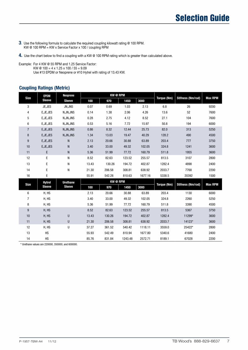
3. Use the following formula to calculate the required coupling kilowatt rating @ 100 RPM. KW @ 100 RPM = KW x Service Factor x 100 / coupling RPM
4. Use the chart below to find a coupling with a KW @ 100 RPM rating which is greater than calculated above.
Example: For 4 KW @ 55 RPM and 1.25 Service Factor: KW @ 100 = 4 x 1.25 x 100 / 55 = 9.09 Use #13 EPDM or Neoprene or #10 Hytrel with rating of 13.43 KW.
Coupling Ratings (Metric)
SizeHytrel Sleeve
Urethane Sleeve
KW @ RPMTorque (Nm) Stifness (Nm/rad) Max RPM
100 970 1450 3000
6 H, HS 2.13 20.66 30.88 63.89 203.4 1130 6000
7 H, HS 3.40 33.00 49.32 102.05 324.8 2260 5250
8 H, HS 5.36 51.99 77.72 160.79 511.8 3390 4500
9 H, HS 8.52 82.63 123.52 255.57 813.5 5367 3750
10 H, HS U 13.43 130.26 194.72 402.87 1282.4 11299* 3600
11 H, HS U 21.30 206.58 308.81 638.92 2033.7 14123* 3600
12 H, HS U 37.27 361.52 540.42 1118.11 3559.0 25422* 2800
13 HS 55.93 542.49 810.94 1677.80 5340.6 41680 2400
14 HS 85.76 831.84 1243.48 2572.71 8189.1 67028 2200
* Urethane values are 220000, 350000, and 600000.
SizeEPDM
SleeveNeoprene
Sleeve
KW @ RPMTorque (Nm) Stifness (Nm/rad) Max RPM
100 970 1450 3000
3 JE,JES JN,JNS 0.07 0.69 1.03 2.13 6.8 26 9200
4 E,JE,JES N,JN,JNS 0.14 1.38 2.06 4.26 13.6 52 7600
5 E,JE,JES N,JN,JNS 0.28 2.75 4.12 8.52 27.1 104 7600
6 E,JE,JES N,JN,JNS 0.53 5.16 7.72 15.97 50.8 194 6000
7 E,JE,JES N,JN,JNS 0.86 8.32 12.44 25.73 82.0 313 5250
8 E,JE,JES N,JN,JNS 1.34 13.03 19.47 40.29 128.2 490 4500
9 E,JE,JES N 2.13 20.66 30.88 63.89 203.4 777 3750
10 E,JE,JES N 3.40 33.00 49.32 102.05 324.8 1241 3600
11 E N 5.36 51.99 77.72 160.79 511.8 1955 3600
12 E N 8.52 82.63 123.52 255.57 813.5 3107 2800
13 E N 13.43 130.26 194.72 402.87 1282.4 4898 2400
14 E N 21.30 206.58 308.81 638.92 2033.7 7768 2200
16 E 55.91 542.28 810.63 1677.16 5338.5 20392 1500
8 TB Wood’s 888-829-6637 .....P-1957-TBW-A4 11/12
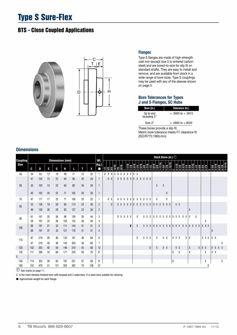
Type S Sure-FlexBTS - Close Coupled Applications
H
CT E
FlangesType S flanges are made of high-strength cast iron (except size 5 is sintered carbon steel) and are bored-to-size for slip fit on standard shafts. They are easy to install and remove, and are available from stock in a wide range of bore sizes. Type S couplings may be used with any of the sleeves shown on page 5.
Bore Tolerances for Types J and S Flanges, SC Hubs Bore (in.) Tolerance (in.)
Up to and + .0005 to + .0015 including 2”
Over 2” + .0005 to +.0020
These bores provide a slip fit.Metric bore tolerance meets F7 clearance fit (ISO/R775:1969,mm)
Dimensions
1/2
5/8
3/4
13/1
67/
815
/16
1 1-1/
161-
1/8
1-3/
161-
1/4
1-5/
161-
3/8
1-7/
161-
1/2
1-9/
161-
5/8
1-11
/16
1-3/
41-
7/8
1-15
/16
2 2-1/
162-
1/8
2-3/
162-
1/4
2-3/
82-
7/16
2-1/
22-
5/8
2-3/
42-
7/8
3 3-3/
83-
7/16
3-5/
83-
7/8
3-15
/16
Stock Bores (in.) 1
Coupling Dimensions (mm) Wt. Size (kg.) C D E G H L T X n
5S 34 83 12 18 48 71 15 25 1 O X X X X X X X X X X
41 102 13 22 64 89 20 28 1 O X X X X X X X X X X X X
6S 33 102 13 22 64 89 20 28 1 X X
40 102 20 22 71 102 20 28 1 X
7S 47 117 17 25 71 100 20 33 1 O X X X X X X X X X X X X X X
8S
53 138 19 29 83 113 23 38 2 O X X X X X X X X X X X X X X X X X X X
49 138 26 29 83 127 23 38 2 X
9S
61 161 20 36 98 129 26 44 3 O X X X X X X X X X X X X X X X X X X X X X 58 161 32 36 105 152 26 44 3 X
10S
69 191 21 33 111 144 31 51 5 O X X X X X X X X X X X X X X X X X X X X X X
68 191 37 33 121 178 31 51 4 X
11S
87 219 29 48 133 181 38 60 8 O X X X X X X X X X X X X X X X X
87 219 40 48 143 203 38 60 7 X
12S 102 255 40 59 146 210 43 68 12 O X X X X X X X X X X X X X 13S 111 298 33 68 171 235 50 78 21 O X X X X X X 14S 114 352 30 83 191 251 57 89 31 O X X 16S 152 479 51 121 203 362 70 108 57 O1 See charts on page 11.
X in the chart denotes finished bore with keyseat and 2 setscrews; O is plain bore suitable for reboring.
n Approximate weight for each flange.
X

9P-1957-TBW-A4 11/12.... TB Wood’s 888-829-6637
Type S Sure-FlexBTS - Close Coupled Applications
14 15 16 19 20 24 25 28 30 32 35 38 42 45 48 50 52 55 60 65 70 80 90
Dimensions
X X X X X X X X
X X X X X X X X X X
X X X X X X X X X
X X X X X X X X
X X X X X X X
X X X X X X X X X X X
X X X X X X X X
X X X X X X
L
X
G
TO REMOVESLEEVE
Max. Bore in. (mm) 1 2
Standard Shallow Bore K.S. Key Bore K.S. Key Bore K.S. Key Keyseat Keyseat
1-3/16 (30) 1-1/4 (32) 1-1/4 1/4 X 1/16 1/4 X 3/16 X 1-3/8 ... ... ... ... ... ...
1-7/16 (37) 1-1/2 (38) ... ... ... ... ... ... ... ... ...
... 1-3/4 (44) 1-1/2 & 1-5/8 3/8 X 1/8 3/8 x 5/16 X s 1-3/4 3/8 X 1/16 3/8 X 1/4 ... ... ... X 1-1/4
... 1-7/8 (48) ... ... ... ... ... ... 1-7/8 1/2 X 1/2 X 5/16 1/16 X 1-9/16
1-5/8 (41) 1-7/8 (48) 1-7/8 1/2 X 1/8 1/2 X 3/8 X 1-7/8 ... ... ... ... ... ...
1-15/16 (49) 2-1/4 (57) 2-1/8 1/2 X 3/16 1/2 X 7/16 X 2-1/8 ... ... ... ... ... ...
... 2-3/8 (60) ... ... ... 2-3/8 5/8 X 1/8 5/8 X 7/16 ... ... ... X 1-7/8
2-1/2 (64) 2-3/4 (70) ... ... ... ... ... ... ... ... ...
... 2-7/8 (73) 2-7/8 3/4 X 1/8 3/4 X 1/2 X 2-1/4 ... ... ... ... ... ...
2-3/4 (70) 3-1/8 (79) 2-7/8 3/4 X 1/4 3/4 X 5/8 X 2-3/4 ... ... ... ... ... ...
... 3-3/8 (86) ... ... ... 3-3/8 7/8 X 3/16 7/8 X 5/8 ... ... ... X 2-5/8
3-3/8 (86) 3-7/16 (87) 3-7/16 7/8 X 3/16 7/8 X 5/8 X 3-7/16 ... ... ... ... ... ...
... 3-7/8 (98) 3-7/8 1 X 1/4 1 X 3/4 X 3 ... ... ... ... ... ...
3-7/8 (98) 3-15/16 (100) ... ... ... ... ... ... ... ... ...
4-1/2 (114) ... ... ... ... ... ... ... ... ... ...
5 (127) ... ... ... ... ... ... ... ... ... ...
5-1/2 (140) 6 (152) ... ... ... ... ... ... ... ... ...
CouplingsType S Sure-Flex couplings are normally supplied with the two-piece E sleeve. However, any of the sleeves shown on page 5 can be used with Type S flanges.
Spacing between internal flange hubs equals L minus 2 times C. Spacing between shafts should be greater than 3.18 mm and less than L minus .85 times the sum of the two “C” dimensions.
To order complete couplings, specify coupling size with flange symbol (S) giving bore and keyseat. Refer to page 3 to order the required coupling.
Metric bore tolerance meets F7 clearance fit (ISO/R775:1969,mm)
Stock Bores (mm) Shallow Keyseat Dimensions 2 (in.)
1 See charts on page 11.2 Some large bore Type S flanges are supplied with shallow keyseats. In these cases, a rectangular key is furnished. The bores involved are listed above.
s 41mm for 38mm bore, 49mm for 41mm bore.

10 TB Wood’s 888-829-6637 .....P-1957-TBW-A4 11/12
Type J Sure-FlexBTS - Close Coupled Applications
STOCK BORES*
9 11 12 14 15 16 19 20 24 25
... X X X X X X
... ... ... X X X X X X X
... ... ... ... ... ... ... ... ... ...
... ... ... ... ... ... ... ... ... ...
7/8 (22)
1 (25)
1-1/8 (29)
1-3/8 (35)
(Inches) (Millimeters)MaxBore (mm)
Dimensions
L
X
G
TO REMOVESLEEVE
H
CT E
L
X
G
TO REMOVESLEEVE
H
CT E
FlangesType J flanges sizes 3, 4 and 5 are manufactured of sintered carbon steel. The powdered metal manufacturing process provides high dimensional accuracy and uniform material properties for high strength. Size 6 is made of high strength cast iron. All flanges are bored-to-size for a slip fit on standard shafts. The outside diameter of the flange is machined so the surface can be used to check alignment without a special tool. Type J flanges can be used with sleeves of any construction except the Hytrel. Each flange has a keyseat and two setscrews (1) over the keyway and the other at 90.
CouplingsType J Sure-Flex Couplings are bored-to-size. Normally, they em ploy the one-piece JE sleeve, or the one-piece JES sleeve with saw cut to permit replacement where there is insufficient gap between shafts.
Spacing between internal flange hubs equals G. Spacing between shafts should be greater than 3.17 mm and less than L minus .85 times the sum of the two “C” dimensions.
To order complete couplings, specify coupling size with flange symbol (J) giving bore and keyseat. Refer to page 3 to order the required coupling.
*We do not recommend reboring the 3J and 4J Flanges. See page 11 for standard keyseat dimensions and page 8 for bore tolerances.
n Approximate weight for each flange.
Product Dimensions (mm) Wt. No. (kg.) C D E G H L T X n
3J 20 52 10 10 38 50 10 16 0.14 X X X X X
4J 22 63 11 16 41 60 11 16 0.18 X X X X X X
5J 27 83 12 19 48 72 15 23 0.41 X X X X X X X
6J 33 102 14 22 64 89 19 28 0.54 X X X X X X X X X
3/8
1/2
5/8
3/4
7/8
15/1
6
1
1-1/
8
1-3/
16
1-1/
4
1-3/
8

11P-1957-TBW-A4 11/12.... TB Wood’s 888-829-6637
Type B Sure-FlexQD - Closed Coupled Applications
L
X
G
TO REMOVESLEEVE
F
C1
C2
T E
L
X
G
TO REMOVESLEEVE
F
C1
C2
T EDimensions (mm)
*Maximum bore with keyseat. n Approximate weight for each flange.
Dimensions Weight Product Bushing Max.* (kg.)n No. Required C1 C2 D E F G L T X Bore Flange Bushing
6B JA 31 25 102 12 51 22 86 20 28 32 35.56 0.36 7B JA 41 25 117 12 51 25 89 20 33 32 48.26 0.36 8B SH 48 32 138 14 68 29 103 23 28 41 73.66 0.45 9B SD 57 46 161 16 97 37 121 27 45 49 121.92 0.68 10B SK 49 48 191 18 98 41 140 31 51 64 198.12 0.91 11B SF 56 51 219 17 117 48 159 38 60 75 304.80 1.59 12B E 69 67 254 23 152 54 191 43 65 89 457.20 4.08 13B F 95 92 298 27 168 68 222 50 76 100 792.48 6.35 14B F 95 92 352 27 168 83 251 57 89 100 1305.56 6.35 16B J 122 114 479 32 184 121 324 70 108 114 3048.00 9.98
FlangesType B flanges are made of high-strength cast iron the same as Types S, C and SC Sure-Flex flanges. Type B, however, is designed to accommodate Wood’s Sure-Grip Bushing for easy installation and removal. All flanges drilled for “inch” series bushing.
BushingsSure-Grip Bushings offer convenient mounting of the flange to the shaft securely without setscrews. They are tapered and are split through both the bushing flange and taper to provide a clamp fit, eliminating wobble, vibration and fretting corrosion. This is the same bushing used in Wood’s sheaves and pulleys and is readily available everywhere.
CouplingsType B Sure-Flex Coupling are normally supplied with the two-piece E sleeve, and can use any EPDM or Neoprene sleeves. DO NOT use Hytrel sleeves with Type B couplings
Spacing between internal flange hubs equals L minus 2 times C2. Spacing between shafts should be greater than 3.18 mm and less than G.
To order complete couplings, specify coupling size with flange symbol (B) and bushing. Refer to page 3 to order the required coupling. Refer to charts below for bushings.
Bushing Bore Keyseat
JA 15-16 5 x 5 19-20 6 x 6 24-25 8 x 6* 28 8 x 5* SH 24-30 8 x 7 32-35 10 x 8 SDS 24-30 8 x 7 32-38 10 x 8 40-42 12 x 8 SD 24-30 8 x 7 32-38 10 x 8 40-42 12 x 8 SK 24-30 8 x 7 32-38 10 x 8 40-42 12 x 8 45-50 14 x 9 55 16 x 10
Bushing Bore Keyseat
SF 28-30 8 x 7 32-38 10 x 8 40-42 12 x 8 45-50 14 x 9 55 16 x 10 60 18 x 11 65 18 x 8* E 35-38 10 x 8 40-42 12 x 8 45-50 14 x 9 55 16 x 10 60-65 18 x 11 70-75 20 x 12 80 22 x 11* F 45-50 14 x 9 55 16 x 10 60-65 18 x 11 70-75 20 x 12 80-90 22 x 14
Bushing Bore Keyseat
J 50 14 x 9 55 16 x 10 60-65 18 x 11 70-75 20 x 12 80-85 22 x 14 90-95 25 x 14 100 28 x 16
Sure-Grip® Bushing Keyseat Dimensions (mm)
*Shallow key furnished
12 TB Wood’s 888-829-6637 .....P-1957-TBW-A4 11/12
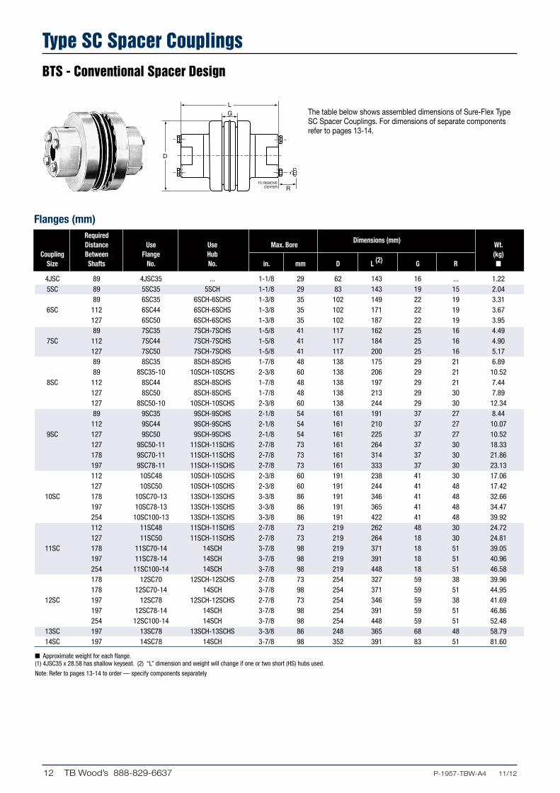
Type SC Spacer CouplingsBTS - Conventional Spacer Design
L
R
G
TO REMOVECENTER
The table below shows assembled dimensions of Sure-Flex Type SC Spacer Couplings. For dimensions of separate components refer to pages 13-14.
Flanges (mm) Required
Dimensions (mm) Distance Use Use Max. Bore Wt. Coupling Between Flange Hub (kg) Size Shafts No. No. in. mm D L (2) G R n
4JSC 89 4JSC35 ... 1-1/8 29 62 143 16 ... 1.22 5SC 89 5SC35 5SCH 1-1/8 29 83 143 19 15 2.04 89 6SC35 6SCH-6SCHS 1-3/8 35 102 149 22 19 3.31 6SC 112 6SC44 6SCH-6SCHS 1-3/8 35 102 171 22 19 3.67 127 6SC50 6SCH-6SCHS 1-3/8 35 102 187 22 19 3.95 89 7SC35 7SCH-7SCHS 1-5/8 41 117 162 25 16 4.49 7SC 112 7SC44 7SCH-7SCHS 1-5/8 41 117 184 25 16 4.90 127 7SC50 7SCH-7SCHS 1-5/8 41 117 200 25 16 5.17 89 8SC35 8SCH-8SCHS 1-7/8 48 138 175 29 21 6.89 89 8SC35-10 10SCH-10SCHS 2-3/8 60 138 206 29 21 10.52 8SC 112 8SC44 8SCH-8SCHS 1-7/8 48 138 197 29 21 7.44 127 8SC50 8SCH-8SCHS 1-7/8 48 138 213 29 30 7.89 127 8SC50-10 10SCH-10SCHS 2-3/8 60 138 244 29 30 12.34 89 9SC35 9SCH-9SCHS 2-1/8 54 161 191 37 27 8.44 112 9SC44 9SCH-9SCHS 2-1/8 54 161 210 37 27 10.07 9SC 127 9SC50 9SCH-9SCHS 2-1/8 54 161 225 37 27 10.52 127 9SC50-11 11SCH-11SCHS 2-7/8 73 161 264 37 30 18.33 178 9SC70-11 11SCH-11SCHS 2-7/8 73 161 314 37 30 21.86 197 9SC78-11 11SCH-11SCHS 2-7/8 73 161 333 37 30 23.13 112 10SC48 10SCH-10SCHS 2-3/8 60 191 238 41 30 17.06 127 10SC50 10SCH-10SCHS 2-3/8 60 191 244 41 48 17.42 10SC 178 10SC70-13 13SCH-13SCHS 3-3/8 86 191 346 41 48 32.66 197 10SC78-13 13SCH-13SCHS 3-3/8 86 191 365 41 48 34.47 254 10SC100-13 13SCH-13SCHS 3-3/8 86 191 422 41 48 39.92 112 11SC48 11SCH-11SCHS 2-7/8 73 219 262 48 30 24.72 127 11SC50 11SCH-11SCHS 2-7/8 73 219 264 18 30 24.81 11SC 178 11SC70-14 14SCH 3-7/8 98 219 371 18 51 39.05 197 11SC78-14 14SCH 3-7/8 98 219 391 18 51 40.96 254 11SC100-14 14SCH 3-7/8 98 219 448 18 51 46.58 178 12SC70 12SCH-12SCHS 2-7/8 73 254 327 59 38 39.96 178 12SC70-14 14SCH 3-7/8 98 254 371 59 51 44.95 12SC 197 12SC78 12SCH-12SCHS 2-7/8 73 254 346 59 38 41.69 197 12SC78-14 14SCH 3-7/8 98 254 391 59 51 46.86 254 12SC100-14 14SCH 3-7/8 98 254 448 59 51 52.48 13SC 197 13SC78 13SCH-13SCHS 3-3/8 86 248 365 68 48 58.79 14SC 197 14SC78 14SCH 3-7/8 98 352 391 83 51 81.60
n Approximate weight for each flange. (1) 4JSC35 x 28.58 has shallow keyseat. (2) “L” dimension and weight will change if one or two short (HS) hubs used.
Note: Refer to pages 13-14 to order — specify components separately

13P-1957-TBW-A4 11/12.... TB Wood’s 888-829-6637
Type SC Couplings and Flanges and HubsType SC Flanges and Hubs
H H
L
C
T E
Flanges (mm) For
Dimensions (mm) Distance Wt. Coupling Flange Between For (kg) Size No. Shafts* Hub D E H L T n
4JSC 4JSC35 79 62 52 51 64 11 .59 5SC 5SC35 89 5SCH 83 20 51 43 15 .59 6SC35 89 6SCH-6SCHS 102 15 64 41 18 .91 6SC 6SC44 112 6SCH-6SCHS 102 26 64 52 18 1.90 6SC50 127 6SCH-6SCHS 102 34 64 60 18 1.23 7SC35 89 7SCH-7SCHS 117 12 71 41 20 1.13 7SC 7SC44 112 7SCH-7SCHS 117 23 71 52 20 1.36 7SC50 127 7SCH-7SCHS 117 31 71 60 20 1.50 8SC35 89 8SCH-8SCHS 138 7 83 41 23 1.68 8SC35-10 89 10SCH-10SCHS 138 7 111 41 23 1.59 8SC 8SC44 112 8SCH-8SCHS 138 18 83 52 23 1.95 8SC50 127 8SCH-8SCHS 138 26 83 60 23 2.18 8SC50-10 127 10SCH-10SCHS 138 26 111 60 23 2.50 9SC35 89 9SCH-9SCHS 161 2 92 43 26 1.86 9SC44 112 9SCH-9SCHS 161 11 92 52 26 2.68 9SC 9SC50 127 9SCH-9SCHS 161 19 92 60 26 2.90 9SC50-11 127 11SCH-11SCHS 161 19 133 60 26 3.18 9SC70-11 178 11SCH-11SCHS 161 44 133 86 26 4.94 9SC78-11 197 11SCH-11SCHS 161 54 133 95 26 5.58 10SC48 112 10SCH-10SCHS 191 9 111 57 31 4.45 10SC50 127 10SCH-10SCHS 191 12 111 60 31 4.63 10SC 10SC70-13 178 13SCH-13SCHS 191 37 156 86 31 6.58 10SC78-13 197 13SCH-13SCHS 191 47 156 95 31 7.48 10SC100-13 254 13SCH-13SCHS 191 50 156 124 31 10.21 11SC48 112 11SCH-11SCHS 219 1 133 38 38 5.67 11SC50 127 11SCH-11SCHS 219 2 133 40 38 5.72 11SC 11SC70-14 178 14SCH 219 27 165 65 38 7.39 11SC78-14 197 14SCH 219 37 165 75 38 8.35 11SC100-14 254 14SCH 219 65 165 103 38 11.16 12SC70 178 12SCH-12SCHS 254 17 146 63 43 10.61 12SC70-14 178 14SCH 254 17 165 63 43 9.66 12SC 12SC78 197 12SCH-12SCHS 254 26 146 72 43 11.48 12SC78-14 197 14SCH 254 26 165 72 43 10.61 12SC100-14 254 14SCH 254 55 165 101 43 13.43 13SC 13SC78 197 13SCH-13SCHS 298 14 156 83 50 17.42 14SC 14SC78 197 14SCH 352 1 165 69 57 25.04
*Flanges can be mixed to form different Between-Shaft Dimensions. See chart page 15. n Approximate weight for each flange. s If using 10HS hub, 7/16-14NC x 2-1/4 long capscrew needed (not furnished).
Tables on pages 13-14 provide dimensional information for flanges and hubs used for Spacer Coupings. For assembled dimensions, see table on page 12. Any of the sleeves shown on page 5 may be used.

14 TB Wood’s 888-829-6637 .....P-1957-TBW-A4 11/12
Hubs Max Bore Stock Bores* (in) Dimensions (mm) Wt. Coupling Hub Plain Bore with Standard Cap Screws (kg) Size No. in mm Bore Keyway & SetScrew C H Furnished (in.) n
4JSC † 1-1/8 29 ... 5/8 – 7/8 – 1 – 1-1/8* 27 51 ... ... 5SC 5SCH 1-1/8 29 1/2 5/8 – 3/4 – 7/8 – 1 – 1-1/8 28 51 4–10 x 1-1/2 .363 6SC 6SCH 1-3/8 35 5/8 3/4 – 7/8 – 1 – 1-1/8 – 1-1/4 – 1-3/8 31 64 4–1/4 x 1-3/4 .635 6SCHS 7/8 22 ... 7/8 25 64 4–1/4 x 1-1/2 .499 7SC 7SCH 1-5/8 41 5/8 7/8 – 1 – 1-1/8 – 1-3/8 – 1-1/2 – 1-5/8 37 71 4–1/4 x 1-7/8 .907 7SCHS 7/8 22 ... 7/8 28 71 4–1/4 x 1-1/2 .680 8SC 8SCH 1-7/8 48 3/4 7/8 – 1 –1-1/8 – 1-3/8 1-1/2 – 1-5/8 – 1-3/4 – 1-7/8 44 83 4–5/16 x 2-1/4 1.452 8SCHS 7/8 22 ... 7/8 31 83 4–5/16 x 1-3/4 .907 9SC 9SCH 2-1/8 54 7/8 1 – 1-1/8 – 1-3/8 – 1-1/2 1-5/8 – 1-3/4 – 1-7/8 – 2-1/8 50 92 4–3/8 x 2-3/4 1.905 9SCHS 1-1/2 38 ... 1-1/8 39 92 4–3/8 x 2-1/4 1.678 10SC 10SCH 2-3/8 60 1-1/8 1-5/8 – 1-7/8 – 2-1/8 – 2-3/8 60 111 4–7/16 x 3-1/4 3.357 10SCHS 1-5/8 41 ... 1-1/8 42 111 4–7/16 x 2-1/2 2.495 11SC 11SCH 2-7/8 73 1-1/8 1-7/8 – 2-1/8 – 2-3/8 – 2-7/8 69 133 4–1/2 x 3-1/2 5.534 11SCHS 1-7/8 48 ... 1-1/8 – 1-5/8 48 133 4–1/2 x 2-3/4 4.218 12SC 12SCH 2-7/8 73 1-3/8 2-1/8 – 2-3/8 – 2-7/8 75 146 4–5/8 x 4 7.530 12SCHS 2-1/2 64 ... 2-3/8 64 146 4–5/8 x 3-1/2 6.396 13SC 13SCH 3-3/8 86 1-3/8 2-3/8 – 2-7/8 – 3-3/8 85 156 4–5/8 x 4-1/2 9.027 13SCHS 2-1/2 64 ... 2-1/8 – 2-3/8 63 156 4–5/8 x 3-1/2 7.258 14SC 142SCH 3-7/8 98 1-5/8 2-3/8 – 2-7/8 – 3-3/8 – 3-7/8 98 165 4–5/8 x 5 10.977
† For 4JSC the hub is an integral part of the flange. 4JSC x 28.58 has 6.35 x 1.59 shallow key seat. . n Approximate weight for each hub.
* See page 8 for bore tolerances, page 11 for standard keyseat dimensions.
H H
L
C
T E
Tables on pages 13-14 provide dimensional information for flanges and hubs used for Spacer Coupings. For assembled dimensions, see table on page 12. Any of the sleeves shown on page 5 may be used.
Type SC Couplings Flanges and HubsType SC Flanges and Hubs

15P-1957-TBW-A4 11/12.... TB Wood’s 888-829-6637
Standard Combination Semi-Spacer
Spacer couplings are available having the most popular between shaft dimensions. Other spacings can be achieved by mixing flanges.
The “Standard” column provides spacings using identical flanges; the “Combination” column mixes flanges; the column headed “Semi-Spacer” uses one flange that is not made for spacer coupling applications and thus does not have a detachable hub.
Standard (mm)
Spacing Uses Flanges*
80 2-( )SC35 111 2-( )SC44 127 2-( )SC50 178 2-( )SC70 197 2-( )SC78 254 2-( )SC100
Semi-Spacer (mm)
Spacing Uses Flanges*
48 S & SC35 58 S & SC44 67 S & SC50 92 S & SC70 102 S & SC78 130 S & SC100
Combination (mm)
Spacing Uses Flanges*
100 SC35 & SC44 108 SC35 & SC50 119 SC44 & SC50 133 SC35 & SC70 143 SC35 & SC78 144 SC44 & SC70 152 SC50 & SC70 154 SC44 & SC78 162 SC50 & SC78 171 SC35 & SC100** 183 SC44 & SC100** 187 SC70 & SC78 191 SC50 & SC100 216 SC70 & SC100 225 SC78 & SC100* Check individual coupling size for flange availability.
** Non-Stock
Note: Other Combinations available — consult factory.
Type SC Spacer CouplingsBetween Shaft Spacing
16 TB Wood’s 888-829-6637 .....P-1957-TBW-A4 11/12
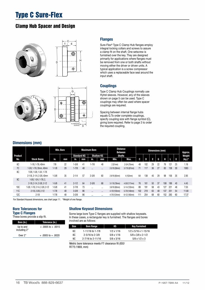
Type C Sure-FlexClamp Hub Spacer and Design
X
G
TO REMOVESLEEVE
H
CT E
L
X
G
TO REMOVESLEEVE
H
CT E
L
FlangesSure-Flex® Type C Clamp Hub flanges employ integral locking collars and screws to assure a clamp fit on the shaft. One setscrew is furnished over the key. They are designed primarily for applications where flanges must be removed from one or both shafts without moving either the driver or driven units. A typical application is a screw compressor which uses a replaceable face seal around the input shaft.
CouplingsType C Clamp Hub Couplings normally use Hytrel sleeves. However, any of the sleeves shown on page 5 can be used. Type C couplings may often be used where spacer couplings are required.
Spacing between internal flange hubs equals G.To order complete couplings, specify coupling size with flange symbol (C), giving bore required. Refer to page 3 to order the required coupling.
Dimensions (mm)
For Standard Keyseat dimensions, see chart page 11. *Weight of one flange.
Metric bore tolerance meets F7 clearance fit (ISO/R775:1969, mm)
Min. Bore Maximum Bore Distance Between
Dimensions (mm) Approx.
Product Standard KS Shallow KS Shafts Weight No. Stock Bores in. mm in. mm in. mm Min. Max. C D E G H L X (kg.)*
6C 1-1/8, 1-7/8, 40mm 7/8 22 1-5/8 41 1-7/8 48 2 (51mm) 2-3/4 (70mm) 49 102 29 22 76 121 25 1.18 7C 1-3/8, 1-7/8, 35mm, 40mm 1-1/8 29 1-7/8 48 ... ... 2-5/16 (59mm) 3-7/16 (87mm) 71 117 36 27 83 138 30 1063 8C 1/3/8, 1-5/8, 1-3/4, 1-7/8 2-1/8, 2-1/4, 2-3/8, 40mm 1-3/8 35 2-1/4 57 2-3/8 60 2-9/16 (65mm) 4 (102mm) 64 138 40 29 98 156 35 2.95 9C 1-5/8, 1-3/4, 1-7/8, 2, 2-1/8, 2-1/4, 2-3/8, 2-1/2 1-5/8 41 2-1/2 64 2-5/8 68 3-1/16 (78mm) 4-5/8 (117mm) 76 161 50 37 108 189 40 4.45 10C 1-5/8, 1-7/8, 2-1/4, 2-3/8, 2-1/2 1-5/8 41 2-7/8 73 ... ... 3-9/16 (90mm) 5-1/4 (133mm) 89 191 58 43 127 221 46 7.53 11C 2-1/8, 2-3/8, 2-1/2 1-7/8 48 3-3/8 86 ... ... 4-1/8 (105mm) 5-7/8 (149mm) 102 219 63 48 137 251 54 11.80 12C 2-1/8 1-7/8 48 3-3/8 86 ... ... 4-7/8 (124mm) 6-1/2 (165mm) 111 254 68 60 152 283 60 17.37
Bore Tolerances for Type C FlangesThese bores provide a slip fit.
Bore (in.) Tolerance (in.)
Up to and + .0005 to + .0015 including 2”
Over 2” + .0005 to + .0020
Shallow Keyseat DimensionsSome large bore Type C flanges are supplied with shallow keyseats. In these cases, a rectangular key is furnished. The flanges and bores involved are as follows:
Size Bore Range KS Key Furnished
6C 1-11/16 to 1-7/8 1/2 x 1/16 1/2 x 5/16 x 1-15/16 8C 2-5/16 to 2-3/8 5/8 x 1/16 5/8 x 3/8 x 2-1/2 9C 2-7/16 to 2-11/16 5/8 x 3/16 5/8 x 1/2 x 3

17P-1957-TBW-A4 11/12.... TB Wood’s 888-829-6637
Installation InstructionsAssembly Dimensions
All dimensions in mm
Sure-Flex flanges (outer metallic parts) and sleeves (inner elastomeric members) come in many sizes and types. First, determine the size and type of components being used. Remove all components from their boxes, and loosely assemble the coupling on any convenient surface. (Do not attempt to install the wire ring on the two-piece E or N sleeve at this time.) Also check maximum RPM values in the table against operating speed. All rubber sleeves (EPDM and Neoprene) have the same ratings for a given size and may be used interchangeably. However, because rubber and Hytrel sleeves have completely different ratings, they never should beused interchangeably.
1. Inspect all coupling components and remove any protective coatings or lubricants from bores, mating surfaces and fasteners. Remove any existing burrs, etc. from the shafts.
2. Slide one coupling flange onto each shaft, using snug-fitting keys where required. When using Type B flanges, follow the instructions furnished with the Sure-Grip bushing.
3. Position the flanges on the shafts to approximately achieve the Y dimension shown in the table. It is usually best to have an equal length of shaft extending into each flange. Move one flange to its final position. Torque fasteners to proper values. Slide the other flange far enough away to install the sleeve. With a two-piece sleeve, do not move the wire ring to its final position; allow it to hang loosely in the groove adjacent to the teeth.
4. Slide the loose flange on the shaft until the sleeve is completely seated in the teeth of each flange. (The “Y” dimension is for reference and not critical.) Secure the flange to the shaft. Different coupling sleeves require different degrees of alignment precision. Locate the alignment values for your sleeve size and type in the table.
5. Check parallel alignment by placing a straight-edge across the two coupling flanges and measuring the maximum offset at various points around the periphery of the coupling without rotating the coupling. If the maximum offset exceeds the figure shown under “Parallel” in the table, realign the shafts.
6. Check angular alignment with a micrometer or caliper. Measure from the outside of one flange to the outside of the other at intervals around the periphery of the coupling. Determine the maximum and minimum dimensions without rotating the coupling. The difference between the maximum and minimum must not exceed the figure given under “Angular” in the table. If a correction is necessary, be sure to recheck the parallel alignment.
7. If the coupling employs the two-piece sleeve with the wire ring, force the ring into its groove in the center of the sleeve. It may be necessary to pry the ring into position with a blunt screwdriver.
8. Install coupling guards per OSHA requirements.
CAUTION: Coupling sleeves may be thrown from the coupling assembly with substantial force when the coupling is subjected to a severe shock load or abuse.
Y
Maximum RPM and Allowable Misalignment
Note: Values shown above apply if the actual torque transmitted is more than 1/4 the coupling rating. For lesser torque, reduce the above values by 1/2.
*Type H and HS sleeves should not be used as direct replacements for EPDM or Neoprene sleeves.
Types JE, JN, JES, JNS, E & N (mm) *Type H & HS (mm) Sleeve Max. Size RPM Parallel Angular Y Parallel Angular Y
3 9200 .25 .89 30.18 ... ... ... 4 7600 .25 1.09 38.10 ... ... ... 5 7600 .38 1.42 49.23 ... ... ... 6 6000 .38 1.78 60.33 .25 .41 60.33 7 5250 .51 2.06 65.10 .31 .51 65.10 8 4500 .51 2.39 74.63 .38 .64 74.63 9 3750 .64 2.80 88.90 .43 .71 88.90 10 3600 .64 3.21 103.20 .51 .81 103.20 11 3600 .81 3.89 123.83 .56 .94 123.83 12 2800 .81 4.44 119.08 .64 1.07 144.48 13 2400 1.02 4.95 169.88 .76 1.27 168.28 14 2200 1.14 6.15 196.85 .89 1.52 196.85 16 1500 1.58 7.38 260.35 ... ... ...
Parallel Angular

18 TB Wood’s 888-829-6637 .....P-1957-TBW-A4 11/12
Notes

TB Wood’s offers a wide range of couplings for industrial applications For over 70 years, TB Wood’s has been designing and manufacturing innovative coupling solutions to meet the requirements for a broad variety of applications spanning many industries. TB Wood’s couplings represent the latest in technology, featuring superior design and exceptional quality to ensure long-lasting performance in all types of industrial applications including printing presses, machine tools, cooling tower fans, food processing equipment, pumps, blowers, electric motors, compressors, mixers, and conveyors,
Form-Flex Disc CouplingsForm-Flex metal disc couplings consist of two hubs, a spacer and two high strength carbon or stainless steel flexible discs. Modified and special designs are commonly supplied to meet specific application conditions. Available in carbon steel, stainless steel or with corrosion resistant coatings. Models available with torque capacities up to 270 kNm; 2,400,000 in.lbs.
See Catalog P-1686-TBW
L-Jaw Elastomeric CouplingsJaw-type elastomeric couplings are an economical, proven solution for general purpose applications. Jaw couplings are easy to install and require no lubrication or maintenance. Four different flexible insert types are available: Buna-N rubber, Urethane, Hytrel™ and Bronze. Jaw couplings are an excellent choice for all light and me-dium duty general purpose industrial applications. Models available with torque capacities up to 0.70 kNm; 6,228 in.lbs.
See Catalog P-1686-TBW
Dura-Flex Elastomeric CouplingsDura-Flex couplings are designed from the ground up using finite element analysis to maximize flex life. Dura-Flex couplings employ a light weight element that absorbs shock loading and torsional vibration. A flexible polyurethane material offers superior chemical, dynamic, and weathering properties. The specially designed “split-in-half flex element” moves stress away from bond, extending flex life. Dura-Flex couplings are directly interchangeable with similar couplings for fast and easy replacement. Models available with torque capacities up to 4.5 kNm; 39,500 in.lbs.
See Catalog P-1686-TBW
G-Flex Grid CouplingsState-of-the-art design from Bibby Transmissions, the original grid coupling manufacturer. G-Flex is an all-metal coupling that provides positive protection against the damaging effects of shock loads and vibration. Aluminum horizontal cover (T10), and all-steel vertical cover (T20) designs are available. G-Flex tapered grid couplings are an excellent choice where torsional flexibility/vibration damping are primary concerns. Models available with torque capacities up to 169 kNm; 1,500,000 in.lbs.
See Catalog P-1686-TBW

Altra Industrial Motion
www.tbwoods.com
440 North Fifth AvenueChambersburg, PA 17201 - USA717-264-7161Fax: 717-264-6420
All Customer Service phone numbers shown in bold
P-1957-TBW-A4 11/12 Printed in USA
Electromagnetic Clutches and Brakes
Warner ElectricElectromagnetic Clutches and Brakes
New Hartford, CT - USA1-800-825-6544For application assistance:1-800-825-9050
St Barthelemy d’Anjou, France+33 (0) 2 41 21 24 24
Precision Electric Coils and Electromagnetic Clutches and Brakes
Columbia City, IN - USA1-260-244-6183
Matrix InternationalElectromagnetic Clutches and Brakes, Pressure Operated Clutches and Brakes
Brechin, Scotland+44 (0) 1356 602000New Hartford, CT - USA1-800-825-6544
Inertia DynamicsSpring Set Brakes; Power On and Wrap Spring Clutch/Brakes
New Hartford, CT - USA1-800-800-6445
Linear Products
Warner LinearLinear Actuators Belvidere, IL - USA1-800-825-6544For application assistance:1-800-825-9050
St Barthelemy d’Anjou, France+33 (0) 2 41 21 24 24
Couplings
Ameridrives Couplings Mill Spindles, Ameriflex,Ameridisc
Erie, PA - USA1-814-480-5000
Gear Couplings
San Marcos, TX - USA1-800-458-0887
Bibby TurboflexDisc, Gear, Grid Couplings, Overload Clutches
Dewsbury, England+44 (0) 1924 460801Boksburg, South Africa+27 11 918 4270
TB Wood’sElastomeric Couplings
Chambersburg, PA - USA1-888-829-6637– Press #5
For application assistance:1-888-829-6637 – Press #7
General Purpose Disc Couplings
San Marcos, TX - USA1-888-449-9439
Ameridrives Power TransmissionUniversal Joints, Drive Shafts, Mill Gear Couplings
Green Bay, WI - USA1-920-593-2444
Huco DynatorkPrecision Couplings and Air Motors
Hertford, England+44 (0) 1992 501900Chambersburg, PA - USA 1-888-829-6637
Lamiflex CouplingsFlexible Couplings, Bearing Isolators, and Coupling Guards
São Paulo, SP - Brasil+55-11-5679-6533
Heavy Duty Clutches and Brakes
Wichita ClutchPneumatic Clutchesand Brakes
Wichita Falls, TX - USA1-800-964-3262Bedford, England+44 (0) 1234 350311
Twiflex LimitedCaliper Brakes and Thrusters
Twickenham, England+44 (0) 20 8894 1161
Industrial ClutchPneumatic and Oil ImmersedClutches and Brakes
Waukesha, WI - USA1-262-547-3357
Gearing
Boston GearEnclosed and Open Gearing, Electrical and Mechanical P.T. Components
Charlotte, NC - USA1-800-825-6544For application assistance:1-800-816-5608
Bauer Gear MotorGeared Motors
Esslingen, Germany+49 (711) 3518 0Somerset, NJ - USA1-732-469-8770
Nuttall Gear andDelroyd Worm GearWorm Gear and Helical Speed Reducers
Niagara Falls, NY - USA1-716-298-4100
Overrunning Clutches
Formsprag Clutch Overrunning Clutches and Holdbacks
Warren, MI - USA1-800-348-0881– Press #1
For application assistance:1-800-348-0881 – Press #2
Marland ClutchRoller Ramp and Sprag Type Overrunning Clutches and Backstops
South Beloit, IL - USA1-800-216-3515
Stieber Clutch Overrunning Clutches and Holdbacks
Heidelberg, Germany+49 (0) 6221 30 47 0
Belted Drives and Sheaves
TB Wood’sBelted Drives
Chambersburg, PA - USA1-888-829-6637 – Press #5
For application assistance:1-888-829-6637 – Press #7
EngineeredBearing Assemblies
Kilian ManufacturingEngineered Bearing Assemblies
Syracuse, NY - USA1-315-432-0700
For information concerning our sales offices in Asia Pacific check our website www.altramotion.com.cn