sure cross performance dx80 wireless i/o...
TRANSCRIPT
Sure Cross® Performance DX80 WirelessI/O Networks
Instruction Manual
Original Instructions132607 Rev. M17 May 2018© Banner Engineering Corp. All rights reserved
132607
Contents
1 The Sure Cross® Performance Wireless Network ...................................................................................................51.1 Sure Cross® Performance Gateways and Nodes .............................................................................................................. 51.2 Sure Cross® Performance GatewayPro .............................................................................................................................51.3 DX83 Ethernet Bridge Overview .........................................................................................................................................61.4 Host Controller Systems .................................................................................................................................................... 61.5 What is FlexPower®? ......................................................................................................................................................... 61.6 Sure Cross® User Configuration Tool ................................................................................................................................ 7
2 Features ...................................................................................................................................................................82.1 DX80 Gateway and Node Components ............................................................................................................................. 82.2 DX80 Gateway and Node Wiring Chamber ........................................................................................................................82.3 DX80 GatewayPro .............................................................................................................................................................. 92.4 DX83 Ethernet Bridge .........................................................................................................................................................92.5 Wiring Diagrams ............................................................................................................................................................... 10
2.5.1 5-pin M12/Euro-style Wiring for Gateways and DX85s ....................................................................................... 102.5.2 5-Pin M12/Euro-style Male Quick Disconnect ..................................................................................................... 102.5.3 DX80...C Wiring .................................................................................................................................................... 102.5.4 Industrial Ethernet Wiring ..................................................................................................................................... 10
2.6 Dimensions .......................................................................................................................................................................112.6.1 Gateways and Nodes ........................................................................................................................................... 112.6.2 GatewayPro ..........................................................................................................................................................122.6.3 DX83 Ethernet Bridge ...........................................................................................................................................122.6.4 DX80...E Housings ................................................................................................................................................13
3 Setting Up Your Wireless Network .......................................................................................................................143.1 Mixing Performance and Non-Performance (150 mW) Radios in the Same Network .................................................... 143.2 Applying Power to the Gateway or Node .........................................................................................................................153.3 Bind Radios to Form Networks ....................................................................................................................................... 153.4 LED Behavior for the Gateways ...................................................................................................................................... 163.5 LED Behavior for the Nodes .............................................................................................................................................173.6 Conducting a Site Survey (Gateway and Nodes) ............................................................................................................. 17
3.6.1 Conduct a Site Survey Using the Menu System .................................................................................................. 173.6.2 Conduct a Site Survey from a Gateway Board Model ........................................................................................ 183.6.3 Improving Your Site Survey Results .....................................................................................................................193.6.4 Improving Your Site Survey Results within a MultiHop Network ......................................................................... 203.6.5 Additional Information ......................................................................................................................................... 21
4 Installing Your Sure Cross® Radios ..................................................................................................................... 234.1 Mounting SureCross Devices Outdoors ..........................................................................................................................23
4.1.1 Watertight Glands and NPT Ports ........................................................................................................................234.2 Other Installation Requirements ......................................................................................................................................244.3 Installation Quick Tips ..................................................................................................................................................... 24
4.3.1 Create a Clear Communication Path ....................................................................................................................244.3.2 Increase the Height of the Antennas .................................................................................................................... 244.3.3 Collocated Radios ................................................................................................................................................ 254.3.4 Be Aware of Seasonal Changes ...........................................................................................................................25
4.4 Installing a Basic Remote Antenna ...................................................................................................................................254.4.1 Weatherproof Remote Antenna Installations ........................................................................................................264.4.2 Installing Remote Antennas ..................................................................................................................................264.4.3 Mount a Dome Antenna to the Enclosure ............................................................................................................ 274.4.4 Use an N-Type, Pole-Mounted Antenna .............................................................................................................. 28
5 Advanced Setup Instructions and Additional Information .....................................................................................305.1 DX80 Menu Structure .......................................................................................................................................................30
5.1.1 RUN Menu ............................................................................................................................................................325.1.2 DINFO (Device Information) Menu ........................................................................................................................335.1.3 FCTRY (Factory) Menu ......................................................................................................................................... 345.1.4 SITE (Site Survey) Menu .......................................................................................................................................355.1.5 DVCFG (Device Configuration) Menu ...................................................................................................................365.1.6 DERR (Device Error) Menu ................................................................................................................................... 37
5.2 Web-based Configuration ................................................................................................................................................ 385.2.1 Accessing the Web-based Configuration Screens ............................................................................................. 395.2.2 Changing the IP Address ..................................................................................................................................... 40
5.3 Binding Mode: What does it do? .....................................................................................................................................415.3.1 Bind Radios to Form Networks ........................................................................................................................... 415.3.2 Manually Assign a Binding Code to a Gateway ................................................................................................... 425.3.3 Manually Assign a Binding Code to a Node .........................................................................................................425.3.4 Automatic Binding Using the Menu Navigation ................................................................................................... 43
Sure Cross® Performance DX80 Wireless I/O Networks
5.3.5 Setting the Network ID in Extended Addressing Mode ........................................................................................445.4 Setting the Maximum System Devices ............................................................................................................................ 445.5 Storage and Sleep Modes ...............................................................................................................................................445.6 Modbus Holding Registers ...............................................................................................................................................455.7 Modbus Communication Parameters .............................................................................................................................. 45
5.7.1 Set the Slave ID on a DX80 Gateway ...................................................................................................................465.7.2 Set the Baud Rate ................................................................................................................................................ 465.7.3 Set the Parity ........................................................................................................................................................46
5.8 Default Output Conditions ................................................................................................................................................475.8.1 Host Link Failure ...................................................................................................................................................475.8.2 Gateway Link Failure ............................................................................................................................................ 475.8.3 Node Link Failure ................................................................................................................................................. 48
5.9 Defining the Units ............................................................................................................................................................. 485.9.1 Interpreting Register Values in the Banner Wireless System ............................................................................... 48
5.10 Setting up the Wireless Network Using the Rotary Dials ............................................................................................... 495.10.1 Rotary Dial Address Mode ................................................................................................................................. 495.10.2 Setting the Network ID Using the Rotary Dials .................................................................................................. 505.10.3 Setting the Device Address Using the Rotary Dials ........................................................................................... 505.10.4 Setting Up Channel Search Mode ......................................................................................................................50
6 System Layouts ..................................................................................................................................................... 526.1 Stand-Alone Systems .......................................................................................................................................................52
6.1.1 Mapped Pairs (DX70) ............................................................................................................................................526.1.2 Gateway with Multiple Nodes (DX80) ...................................................................................................................536.1.3 Gateway Configured as a Modbus Master .......................................................................................................... 54
6.2 Modbus RTU .................................................................................................................................................................... 556.2.1 Modbus RTU Host Controlled Operation .............................................................................................................556.2.2 Modbus RTU with Multiple Slave Devices ........................................................................................................... 566.2.3 Modbus RTU with Multiple Slave Devices - Layout 2 ..........................................................................................57
6.3 Modbus/TCP and EtherNet/IP ......................................................................................................................................... 586.3.1 Host Connected - DX80 GatewayPro .................................................................................................................. 58
6.4 Data Radios ......................................................................................................................................................................596.4.1 Data Radios ..........................................................................................................................................................596.4.2 Data Radios with DX85 Modbus RTU Remote I/O Devices .................................................................................596.4.3 Data Radios with a Gateway as the Modbus Master ...........................................................................................60
7 Sensor Connections .............................................................................................................................................. 617.1 Discrete Inputs ................................................................................................................................................................ 61
7.1.1 Discrete Inputs, Sourcing .....................................................................................................................................617.1.2 Discrete Inputs, Sinking ....................................................................................................................................... 617.1.3 Discrete Inputs, MINI-BEAM ................................................................................................................................ 62
7.2 Discrete Outputs ............................................................................................................................................................. 627.2.1 Discrete Outputs .................................................................................................................................................. 62
7.3 Analog Inputs .................................................................................................................................................................. 627.3.1 Analog Inputs, Powered using SureCross Device Terminals ............................................................................... 627.3.2 Analog Inputs, Powered from Switch Power ....................................................................................................... 637.3.3 Analog Inputs, Powered Externally ...................................................................................................................... 637.3.4 Analog Inputs, Temperature Sensors ...................................................................................................................637.3.5 Analog Inputs, QT50U Long-Range Ultrasonic Sensor ....................................................................................... 64
7.4 Analog Outputs ............................................................................................................................................................... 647.4.1 Analog Outputs, Three-Wire Sensors ...................................................................................................................647.4.2 Analog Outputs, Drive Motor Controllers ............................................................................................................. 64
8 Sure Cross® Power Solutions ............................................................................................................................... 658.1 Using 10 to 30 V dc Power ...............................................................................................................................................658.2 What is FlexPower®? ....................................................................................................................................................... 65
8.2.1 Switch Power ....................................................................................................................................................... 658.2.2 FlexPower with Integrated Battery ....................................................................................................................... 66
8.3 Battery Life Calculations .................................................................................................................................................. 668.3.1 Battery Life for Some Analog Sensors ................................................................................................................. 668.3.2 Discrete Configuration ..........................................................................................................................................678.3.3 Battery Life of Temperature and Humidity Sensor ...............................................................................................688.3.4 Battery Life of Wireless Q45 Nodes ..................................................................................................................... 698.3.5 Battery Life for a P6 Node Connected to a Vibration and Temperature (VT1) Sensor .........................................698.3.6 Battery Life for a Q45VA or a Q45VT/Q45U Node with 1-Wire Serial Sensor .....................................................698.3.7 Calculating Battery Life ........................................................................................................................................ 70
9 Maintenance .......................................................................................................................................................... 729.1 Replacing the Main Body Gasket .....................................................................................................................................729.2 Replacing the Rotary Dial Access Cover ......................................................................................................................... 729.3 Battery Replacement ........................................................................................................................................................72
9.3.1 Install or Replace the Battery ............................................................................................................................... 729.3.2 Install or Replace the Battery (DX80 Models) ......................................................................................................739.3.3 Install or Replace the Battery (DX99...D Models) ................................................................................................ 73
Sure Cross® Performance DX80 Wireless I/O Networks
10 Troubleshooting ...................................................................................................................................................7510.1 Startup Problems ........................................................................................................................................................... 7510.2 LED Message Codes ......................................................................................................................................................7510.3 LCD Message Codes ..................................................................................................................................................... 77
10.3.1 Modbus Message Codes for Register 8 .............................................................................................................7710.4 Inputs and Outputs .........................................................................................................................................................7810.5 Radio Link Time-Out and Recovery (Non-Host Connected Systems) ........................................................................... 78
11 Accessories ......................................................................................................................................................... 8011.1 Selecting an Enclosure ..................................................................................................................................................80
11.1.1 Polycarbonate Enclosures ..................................................................................................................................8011.1.2 Fiberglass Enclosures ....................................................................................................................................... 81
11.2 Selecting an Antenna .................................................................................................................................................... 8111.2.1 Antennas: Rubber RP-SMA ...............................................................................................................................8211.2.2 Antennas: Dome ................................................................................................................................................8211.2.3 Antennas: Other ................................................................................................................................................ 8211.2.4 Antennas: Fiberglass N-Type ............................................................................................................................. 8311.2.5 Antennas: Yagi N-Type ..................................................................................................................................... 8311.2.6 Antennas: Cellular ............................................................................................................................................. 8311.2.7 Antenna Cables: RP-SMA to RP-SMA ..............................................................................................................8311.2.8 Antenna Cables: RP-SMA to N-Type ................................................................................................................8411.2.9 Antenna Cables: N-Type ................................................................................................................................... 8411.2.10 Surge Suppressors ...........................................................................................................................................84
11.3 Power Supplies .............................................................................................................................................................. 8411.3.1 DC Power Supplies ............................................................................................................................................ 8511.3.2 FlexPower Supplies and Replacement Batteries ............................................................................................... 85
11.4 Relays ............................................................................................................................................................................8511.5 Sensors .......................................................................................................................................................................... 86
11.5.1 Sensors with a Serial Interface ..........................................................................................................................8611.5.2 Sensors with a Modbus Interface .......................................................................................................................8711.5.3 Sensors - Other ................................................................................................................................................. 8811.5.4 Sensors for FlexPower Devices ......................................................................................................................... 89
11.6 Brackets and Mounting Options ................................................................................................................................... 8911.7 Cables ............................................................................................................................................................................ 90
11.7.1 Ethernet Cables ..................................................................................................................................................9011.7.2 Adapter Cables ...................................................................................................................................................9111.7.3 Splitter Cables ....................................................................................................................................................9111.7.4 Euro-Style Cordsets - Single Ended .................................................................................................................. 9211.7.5 Euro-Style Cordsets - Double Ended ................................................................................................................9311.7.6 Other Cables ...................................................................................................................................................... 94
11.8 Other Accessories .......................................................................................................................................................... 9411.8.1 DX85 Modbus RTU Remote I/O Devices ........................................................................................................... 9411.8.2 Cable Glands and Plugs ....................................................................................................................................9411.8.3 Hardware and Replacement Parts ..................................................................................................................... 9511.8.4 Metal Housing Accessories ................................................................................................................................95
12 Sure Cross® Radio Certifications ........................................................................................................................9712.1 FCC Certification, 900MHz ............................................................................................................................................ 9712.2 FCC Certification, 900 MHz, 1 Watt Radios ...................................................................................................................9812.3 FCC Certification, 2.4GHz ..............................................................................................................................................9812.4 Certified For Use in the Following Countries ..................................................................................................................9912.5 Exporting Sure Cross® Radios .....................................................................................................................................102
13 Warnings ............................................................................................................................................................10313.1 Banner Engineering Corp. Limited Warranty ...............................................................................................................10313.2 Contact Us ................................................................................................................................................................... 103
Sure Cross® Performance DX80 Wireless I/O Networks
1 The Sure Cross® Performance Wireless Network
Node
Gateway
Node
FlexPower Nodewith IntegratedBattery
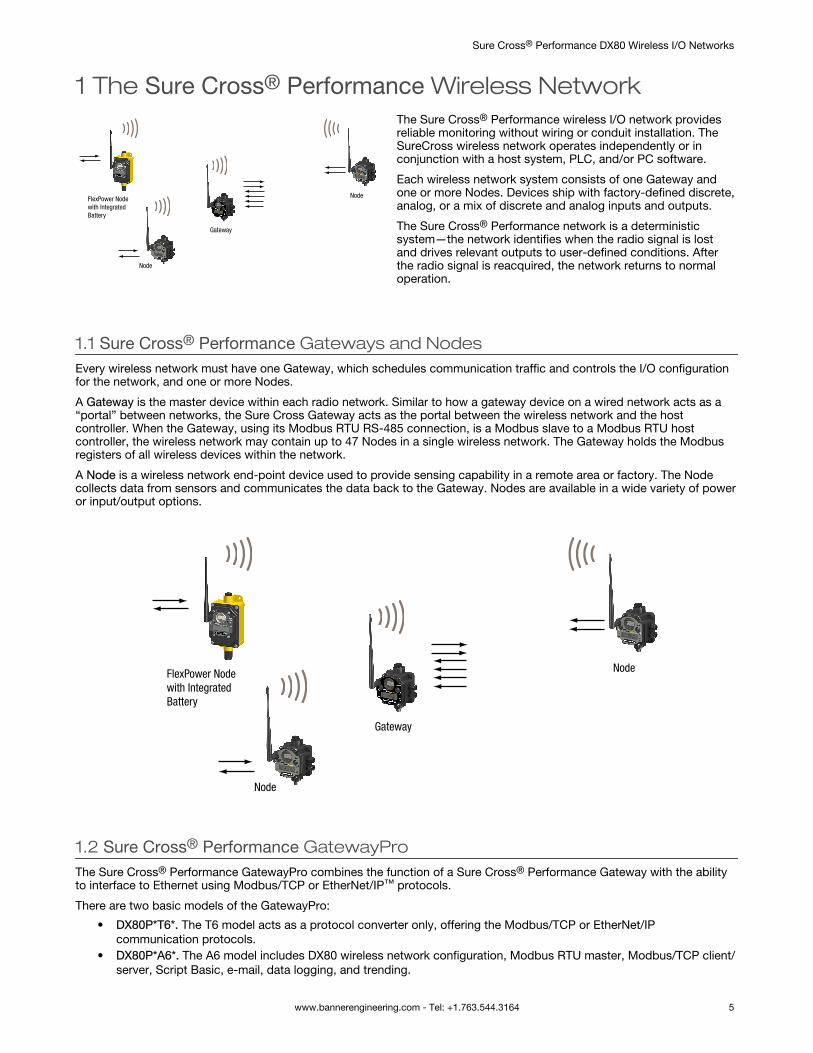
The Sure Cross® Performance wireless I/O network providesreliable monitoring without wiring or conduit installation. TheSureCross wireless network operates independently or inconjunction with a host system, PLC, and/or PC software.
Each wireless network system consists of one Gateway andone or more Nodes. Devices ship with factory-defined discrete,analog, or a mix of discrete and analog inputs and outputs.
The Sure Cross® Performance network is a deterministicsystem—the network identifies when the radio signal is lostand drives relevant outputs to user-defined conditions. Afterthe radio signal is reacquired, the network returns to normaloperation.
1.1 Sure Cross® Performance Gateways and NodesEvery wireless network must have one Gateway, which schedules communication traffic and controls the I/O configurationfor the network, and one or more Nodes.
A Gateway is the master device within each radio network. Similar to how a gateway device on a wired network acts as a“portal” between networks, the Sure Cross Gateway acts as the portal between the wireless network and the hostcontroller. When the Gateway, using its Modbus RTU RS-485 connection, is a Modbus slave to a Modbus RTU hostcontroller, the wireless network may contain up to 47 Nodes in a single wireless network. The Gateway holds the Modbusregisters of all wireless devices within the network.
A Node is a wireless network end-point device used to provide sensing capability in a remote area or factory. The Nodecollects data from sensors and communicates the data back to the Gateway. Nodes are available in a wide variety of poweror input/output options.
Node
Gateway
Node
FlexPower Nodewith IntegratedBattery
1.2 Sure Cross® Performance GatewayProThe Sure Cross® Performance GatewayPro combines the function of a Sure Cross® Performance Gateway with the abilityto interface to Ethernet using Modbus/TCP or EtherNet/IP™ protocols.
There are two basic models of the GatewayPro:
• DX80P*T6*. The T6 model acts as a protocol converter only, offering the Modbus/TCP or EtherNet/IPcommunication protocols.
• DX80P*A6*. The A6 model includes DX80 wireless network configuration, Modbus RTU master, Modbus/TCP client/server, Script Basic, e-mail, data logging, and trending.
Sure Cross® Performance DX80 Wireless I/O Networks
www.bannerengineering.com - Tel: +1.763.544.3164 5
Connect a host controller system to the GatewayPro using its industrial Ethernet connection. To connect the GatewayPro tothe host system without using an Ethernet switchbox/hub, some host systems may require a crossover cable.
By default, the GatewayPro is configured to use Modbus/TCP. To use EtherNet/IP, connect the GatewayPro to a managedswitch and you must use the Web Configuration tool to select EtherNet/IP. For more information, see SureCross WirelessI/O Product Manual or Host Configuration Manual.
1.3 DX83 Ethernet Bridge OverviewA DX83 Ethernet Bridge connected to a DX80 Gateway functions like a DX80 GatewayPro and allows the Gateway to haveI/O points. The DX83 Ethernet Bridge adds the Web page configuration ability to a Gateway-Node wireless network as wellas the ability to interface to Ethernet using Modbus/TCP or EtherNet/IP protocols.
There are two basic DX83 models:• DX83T acts as a protocol converter only, offering the Modbus/TCP or EtherNet/IP communication protocols.• DX83A includes DX80 wireless network configuration, Modbus RTU master, Modbus/TCP client/server, Script
Basic, e-mail, data logging, and trending.
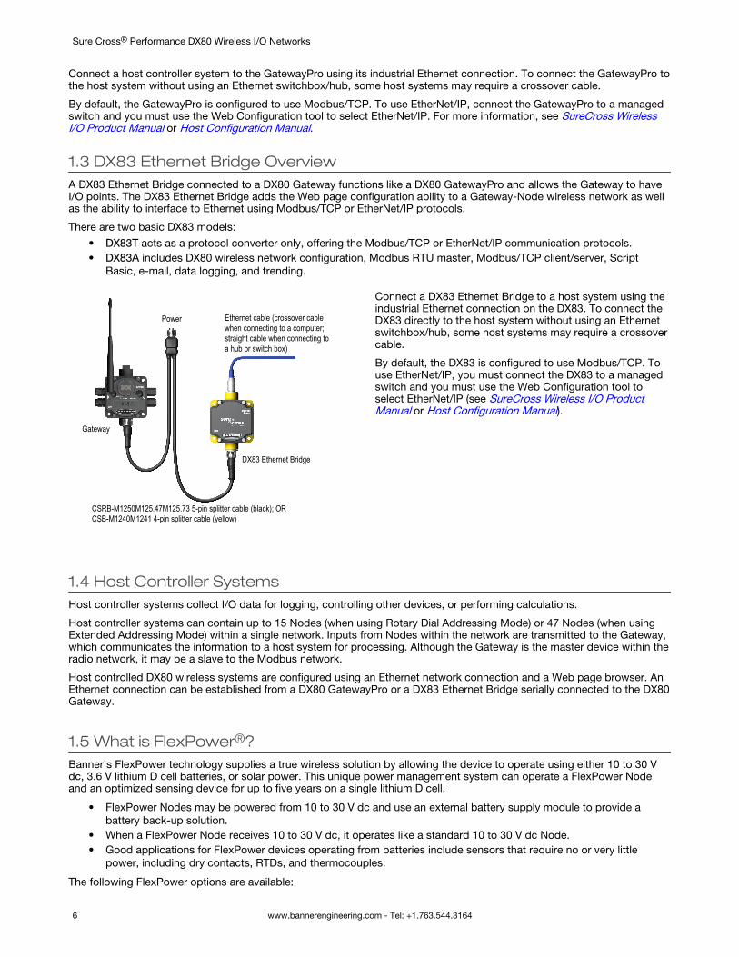
Gateway
Power
DX83 Ethernet Bridge
Ethernet cable (crossover cable when connecting to a computer; straight cable when connecting toa hub or switch box)
CSRB-M1250M125.47M125.73 5-pin splitter cable (black); ORCSB-M1240M1241 4-pin splitter cable (yellow)
Connect a DX83 Ethernet Bridge to a host system using theindustrial Ethernet connection on the DX83. To connect theDX83 directly to the host system without using an Ethernetswitchbox/hub, some host systems may require a crossovercable.
By default, the DX83 is configured to use Modbus/TCP. Touse EtherNet/IP, you must connect the DX83 to a managedswitch and you must use the Web Configuration tool toselect EtherNet/IP (see SureCross Wireless I/O ProductManual or Host Configuration Manual).
1.4 Host Controller SystemsHost controller systems collect I/O data for logging, controlling other devices, or performing calculations.
Host controller systems can contain up to 15 Nodes (when using Rotary Dial Addressing Mode) or 47 Nodes (when usingExtended Addressing Mode) within a single network. Inputs from Nodes within the network are transmitted to the Gateway,which communicates the information to a host system for processing. Although the Gateway is the master device within theradio network, it may be a slave to the Modbus network.
Host controlled DX80 wireless systems are configured using an Ethernet network connection and a Web page browser. AnEthernet connection can be established from a DX80 GatewayPro or a DX83 Ethernet Bridge serially connected to the DX80Gateway.
1.5 What is FlexPower®?Banner’s FlexPower technology supplies a true wireless solution by allowing the device to operate using either 10 to 30 Vdc, 3.6 V lithium D cell batteries, or solar power. This unique power management system can operate a FlexPower Nodeand an optimized sensing device for up to five years on a single lithium D cell.
• FlexPower Nodes may be powered from 10 to 30 V dc and use an external battery supply module to provide abattery back-up solution.
• When a FlexPower Node receives 10 to 30 V dc, it operates like a standard 10 to 30 V dc Node.• Good applications for FlexPower devices operating from batteries include sensors that require no or very little
power, including dry contacts, RTDs, and thermocouples.
The following FlexPower options are available:
Sure Cross® Performance DX80 Wireless I/O Networks
6 www.bannerengineering.com - Tel: +1.763.544.3164
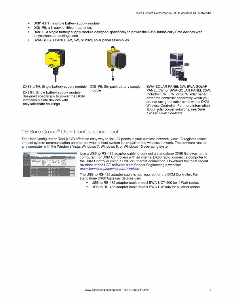
• DX81-LITH, a single battery supply module;• DX81P6, a 6-pack of lithium batteries;• DX81H, a single battery supply module designed specifically to power the DX99 Intrinsically Safe devices with
polycarbonate housings; and• BWA-SOLAR PANEL 3W, 5W, or 20W, solar panel assemblies.
DX81-LITH: Single battery supply module
DX81H: Single battery supply moduledesigned specifically to power the DX99Intrinsically Safe devices withpolycarbonate housings
DX81P6: Six-pack battery supplymodule
BWA-SOLAR PANEL 3W, BWA-SOLARPANEL 5W, or BWA-SOLAR PANEL 20W:Includes 3 W, 5 W, or 20 W solar panel;order the controller separately when youare not using the solar panel with a DXMWireless Controller. For more informationabout solar power solutions, see SureCross® Solar Solutions.
1.6 Sure Cross® User Configuration ToolThe User Configuration Tool (UCT) offers an easy way to link I/O points in your wireless network, view I/O register values,and set system communication parameters when a host system is not part of the wireless network. The software runs onany computer with the Windows Vista, Windows 7, Windows 8, or Windows 10 operating system.
Use a USB to RS-485 adapter cable to connect a standalone DX80 Gateway to thecomputer. For DXM Controllers with an internal DX80 radio, connect a computer tothe DXM Controller using a USB or Ethernet connection. Download the most recentrevisions of the UCT software from Banner Engineering's website: www.bannerengineering.com/wireless.
The USB to RS-485 adapter cable is not required for the DXM Controller. Forstandalone DX80 Gateway devices use:
• USB to RS-485 adapter cable model BWA-UCT-900 for 1 Watt radios• USB to RS-485 adapter cable model BWA-HW-006 for all other radios
Sure Cross® Performance DX80 Wireless I/O Networks
www.bannerengineering.com - Tel: +1.763.544.3164 7

2 FeaturesThe following feature callouts refer to the DX80 Gateway and Node models, the GatewayPro, and the DX83 Ethernet Bridge.The wiring diagrams include information for connection power and sensors using the 5-pin Euro-style connect, the terminalwiring board, and the Industrial Ethernet connection on the DX83 and GatewayPro.
2.1 DX80 Gateway and Node ComponentsThe DX80 Gateway and Node use the same housing and include the same physical features.
1
2
34
5
67
1. Port, NPT gland, or plug. If unused, install the provided pluginto the 1/2 NPT threaded port. Refer to the Installation sectionif an IP67 seal is required.
2. Rotary switch 1 (left). Sets the Network ID (NID) to ahexidecimal value from 0 to F, for a total of 16 Network IDs. AGateway and its corresponding Nodes must be assigned thesame Network ID.
Rotary switch 2 (right). On the Gateway, sets the Gateway’sLCD viewing device address. The Gateway is predefined asDevice Address 0. On the Node, sets the Node’s DeviceAddress (hexidecimal 1 to F). Each Node within a network musthave a unique Node Device Address.
3. Push button 1. Single-click to advance across all top-levelDX80 menus. Single-click to move down interactive menus,once a top-level menu is chosen. Button 1 is also used to wakeintegrated battery models from the hibernation mode they shipin.
4. Push button 2. Double-click to select a menu and to entermanual scrolling mode. Double-click to move up one level at atime.
5. LED 1 and 2. Provide real-time feedback to the user regarding RF link status, serial communications activity, and theerror state.
6. LCD Display. Six-character display provides run mode user information and shows enabled I/O point status. Thisdisplay allows the user to conduct a Site Survey (RSSI) and modify other DX80 configuration parameters without the useof a PC or other external software interfaces. On the Node, after 15 minutes of inactivity, the LCD goes blank. Press anybutton to refresh the display.
7. 5-Pin M12 Euro-style quick-disconnect serial port
2.2 DX80 Gateway and Node Wiring ChamberThe DX80 Gateway and Node use the same housing and terminal block for wiring.
12
3
4
5
1. Housing. The rugged, industrial DX80 housing meets IECIP67 standards.
2. Mounting hold, #10/M5 clearance. Mounting Holes acceptmetric M5 or UNC/UNF #10 hardware -- DIN rail mount adapterbracket available.
3. Wiring terminal strip. The 16 spring-clip type wiring terminalsaccept wire sizes: AWG 12-28 or 2.5 sq mm.
4. Port, PG-7 gland or blank. The PG-7 threaded ports canaccept provided cable glands or blanks.
5. Ribbon connector. Ribbon cable connects wiring base toLCD/radio.
Sure Cross® Performance DX80 Wireless I/O Networks
8 www.bannerengineering.com - Tel: +1.763.544.3164
The GatewayPro has no serviceable parts inside the housing and no wiring chamber. During setup or standard operation,there should not be a need to open the GatewayPro.
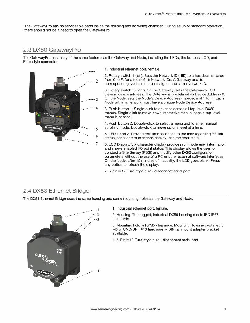
2.3 DX80 GatewayProThe GatewayPro has many of the same features as the Gateway and Node, including the LEDs, the buttons, LCD, andEuro-style connector.
1
2
3
4
56
7
1. Industrial ethernet port, female.
2. Rotary switch 1 (left). Sets the Network ID (NID) to a hexidecimal valuefrom 0 to F, for a total of 16 Network IDs. A Gateway and itscorresponding Nodes must be assigned the same Network ID.
3. Rotary switch 2 (right). On the Gateway, sets the Gateway’s LCDviewing device address. The Gateway is predefined as Device Address 0.On the Node, sets the Node’s Device Address (hexidecimal 1 to F). EachNode within a network must have a unique Node Device Address.
3. Push button 1. Single-click to advance across all top-level DX80menus. Single-click to move down interactive menus, once a top-levelmenu is chosen.
4. Push button 2. Double-click to select a menu and to enter manualscrolling mode. Double-click to move up one level at a time.
5. LED 1 and 2. Provide real-time feedback to the user regarding RF linkstatus, serial communications activity, and the error state.
6. LCD Display. Six-character display provides run mode user informationand shows enabled I/O point status. This display allows the user toconduct a Site Survey (RSSI) and modify other DX80 configurationparameters without the use of a PC or other external software interfaces.On the Node, after 15 minutes of inactivity, the LCD goes blank. Pressany button to refresh the display.
7. 5-pin M12 Euro-style quick disconnect serial port.
2.4 DX83 Ethernet BridgeThe DX83 Ethernet Bridge uses the same housing and same mounting holes as the Gateway and Node.
123
4
1. Industrial ethernet port, female.
2. Housing. The rugged, industrial DX80 housing meets IEC IP67standards.
3. Mounting hold, #10/M5 clearance. Mounting Holes accept metricM5 or UNC/UNF #10 hardware -- DIN rail mount adapter bracketavailable.
4. 5-Pin M12 Euro-style quick-disconnect serial port
Sure Cross® Performance DX80 Wireless I/O Networks
www.bannerengineering.com - Tel: +1.763.544.3164 9
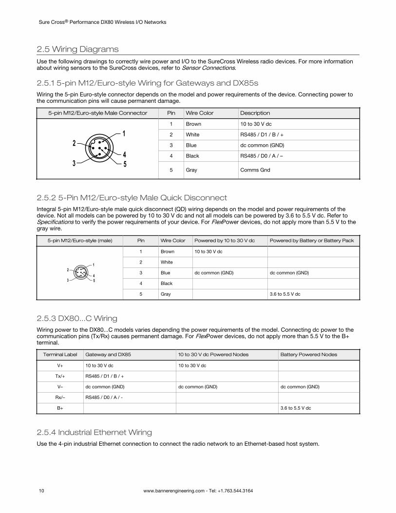
2.5 Wiring DiagramsUse the following drawings to correctly wire power and I/O to the SureCross Wireless radio devices. For more informationabout wiring sensors to the SureCross devices, refer to Sensor Connections.
2.5.1 5-pin M12/Euro-style Wiring for Gateways and DX85sWiring the 5-pin Euro-style connector depends on the model and power requirements of the device. Connecting power tothe communication pins will cause permanent damage.
5-pin M12/Euro-style Male Connector Pin Wire Color Description
1
453
2
1 Brown 10 to 30 V dc
2 White RS485 / D1 / B / +
3 Blue dc common (GND)
4 Black RS485 / D0 / A / –
5 Gray Comms Gnd
2.5.2 5-Pin M12/Euro-style Male Quick DisconnectIntegral 5-pin M12/Euro-style male quick disconnect (QD) wiring depends on the model and power requirements of thedevice. Not all models can be powered by 10 to 30 V dc and not all models can be powered by 3.6 to 5.5 V dc. Refer toSpecifications to verify the power requirements of your device. For FlexPower devices, do not apply more than 5.5 V to thegray wire.
5-pin M12/Euro-style (male) Pin Wire Color Powered by 10 to 30 V dc Powered by Battery or Battery Pack
1
453
2
1 Brown 10 to 30 V dc
2 White
3 Blue dc common (GND) dc common (GND)
4 Black
5 Gray 3.6 to 5.5 V dc
2.5.3 DX80...C WiringWiring power to the DX80...C models varies depending the power requirements of the model. Connecting dc power to thecommunication pins (Tx/Rx) causes permanent damage. For FlexPower devices, do not apply more than 5.5 V to the B+terminal.
Terminal Label Gateway and DX85 10 to 30 V dc Powered Nodes Battery Powered Nodes
V+ 10 to 30 V dc 10 to 30 V dc
Tx/+ RS485 / D1 / B / +
V– dc common (GND) dc common (GND) dc common (GND)
Rx/– RS485 / D0 / A / -
B+ 3.6 to 5.5 V dc
2.5.4 Industrial Ethernet WiringUse the 4-pin industrial Ethernet connection to connect the radio network to an Ethernet-based host system.
Sure Cross® Performance DX80 Wireless I/O Networks
10 www.bannerengineering.com - Tel: +1.763.544.3164
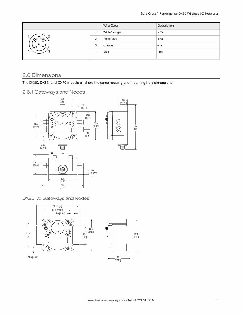
Wire Color Description
1
4 3
21 White/orange + Tx
2 White/blue +Rx
3 Orange –Tx
4 Blue –Rx
2.6 DimensionsThe DX80, DX83, and DX70 models all share the same housing and mounting hole dimensions.
2.6.1 Gateways and Nodes65.0
[2.56”]
65.0[2.56”]
80.3[3.16”]
80.8[3.18”]
60[2.36”]
120[4.72”]
127[5”]
19[0.75”]
30.65[1.21”]
22.2[0.875”]
7.9[0.31”]
7.65[0.30”]
14.67[0.578”]
DX80...C Gateways and Nodes
7.9 [0.31”]
80.8[3.18”]
65.0 [2.56”]
80.3[3.16”]65.0
[2.56”]
7.65 [0.30”] 60[2.36”]
45.7[1.8”]
101.6 [4”]
Sure Cross® Performance DX80 Wireless I/O Networks
www.bannerengineering.com - Tel: +1.763.544.3164 11
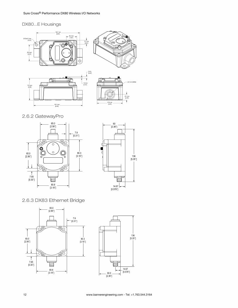
DX80...E Housings
6 mm[0.24”]
3.2 mm[0.13”]
167.4 mm[6.59”]
75.3 mm[2.96”]
2X 12-14 NPSM
20.1 mm[0.79”]
87.6 mm[3.45”]
13.7 mm[0.54”]
36.2 mm[1.42”]
148.1 mm[5.83”]
55.9 mm[2.20”]
2X Dia 8.3 mm[0.33”]
2.6.2 GatewayPro65.0
[2.56’’]
65.0[2.56’’]
80.3[3.16’’]
80.8[3.18’’]
136[5.35’’]
7.9[0.31’’]
7.65[0.30’’]
60[2.36’’]
14.67[0.578’’]
2.6.3 DX83 Ethernet Bridge
65.0[2.56’’]
7.9[0.31’’]
80.3[3.16’’]
65.0[2.56’’]
7.65[0.30’’]
80.8[3.18’’]
136[5.35’’]
60.0[2.36’’]
14.67[0.578’’]
Sure Cross® Performance DX80 Wireless I/O Networks
12 www.bannerengineering.com - Tel: +1.763.544.3164
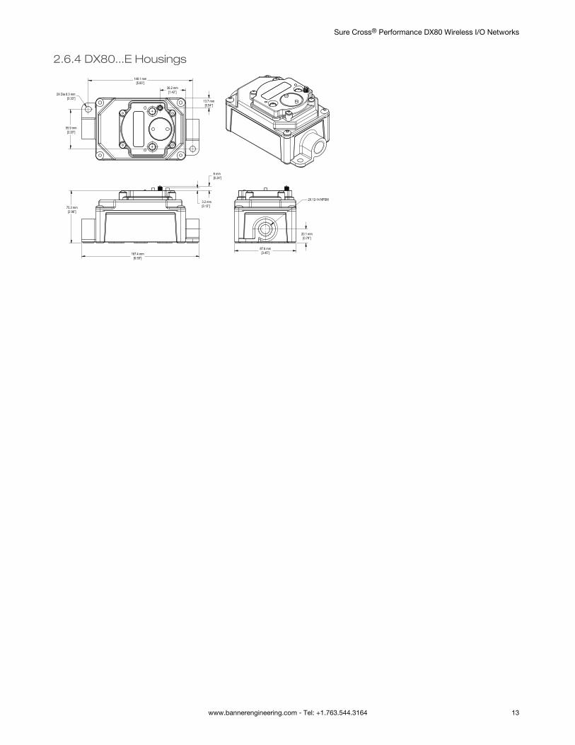
2.6.4 DX80...E Housings
6 mm[0.24”]
3.2 mm[0.13”]
167.4 mm[6.59”]
75.3 mm[2.96”]
2X 12-14 NPSM
20.1 mm[0.79”]
87.6 mm[3.45”]
13.7 mm[0.54”]
36.2 mm[1.42”]
148.1 mm[5.83”]
55.9 mm[2.20”]
2X Dia 8.3 mm[0.33”]
Sure Cross® Performance DX80 Wireless I/O Networks
www.bannerengineering.com - Tel: +1.763.544.3164 13
3 Setting Up Your Wireless NetworkTo set up and install your wireless network, follow these steps.
Disconnect the power from your Sure Cross devices.
1. Configure the DIP switches of all devices. For DIP switch configurations, refer to the product's datasheet.2. If your device has I/O, connect the sensors to the Sure Cross devices. For available I/O, refer to the product's
datasheet. If your device does not have I/O, skip this step.3. Refer to the wiring diagrams to apply power to all devices.
• For housed models, the Gateway's LED 1 is solid green and the Node's LED 2 flashes red to indicate there is noradio link to the Gateway.
• For board-level models, the Gateway's LED is solid green and the Node's LED flashes red to indicate there is noradio link to the Gateway.
4. Form the wireless network by binding the Nodes to the Gateway.5. Observe the LED behavior to verify the devices are communicating with each other.
• For housed models, the Gateway's LED 1 is solid green and the Node's LED 1 flashes green to indicate it iscommunicating with the Gateway.
• For board-level models, the Gateway's LED is solid green and the Node's LED flashes green to indicate it iscommunicating with the Gateway.
6. Configure any I/O points to use the sensors connected to the Sure Cross devices.7. Conduct a site survey between the Gateway and Nodes.8. Install your wireless sensor network components.
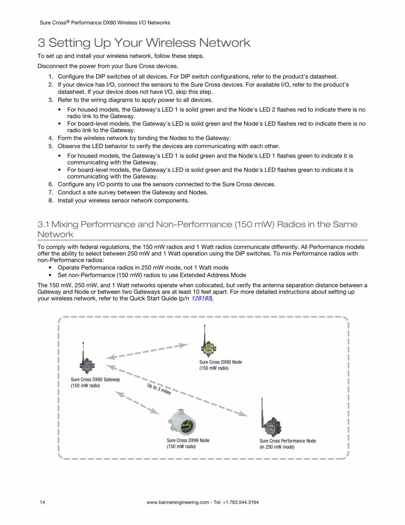
3.1 Mixing Performance and Non-Performance (150 mW) Radios in the SameNetworkTo comply with federal regulations, the 150 mW radios and 1 Watt radios communicate differently. All Performance modelsoffer the ability to select between 250 mW and 1 Watt operation using the DIP switches. To mix Performance radios withnon-Performance radios:
• Operate Performance radios in 250 mW mode, not 1 Watt mode• Set non-Performance (150 mW) radios to use Extended Address Mode
The 150 mW, 250 mW, and 1 Watt networks operate when collocated, but verify the antenna separation distance between aGateway and Node or between two Gateways are at least 10 feet apart. For more detailed instructions about setting upyour wireless network, refer to the Quick Start Guide (p/n 128185).
Sure Cross DX80 Gateway (150 mW radio)
Sure Cross DX80 Node (150 mW radio)
Sure Cross Performance Node (in 250 mW mode)
Sure Cross DX99 Node (150 mW radio)
Up to 3 miles
Sure Cross® Performance DX80 Wireless I/O Networks
14 www.bannerengineering.com - Tel: +1.763.544.3164
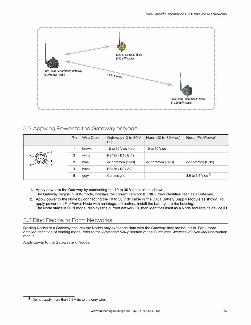
Sure Cross Performance Gateway (in 250 mW mode)
Sure Cross Performance Node (in 250 mW mode)
Sure Cross DX80 Node (150 mW radio)
Up to 6 miles
3.2 Applying Power to the Gateway or Node
Pin Wire Color Gateway (10 to 30 Vdc)
Node (10 to 30 V dc) Node (FlexPower)
1
453
2
1 brown 10 to 30 V dc input 10 to 30 V dc
2 white RS485 / D1 / B / +
3 blue dc common (GND) dc common (GND) dc common (GND)
4 black RS485 / D0 / A / -
5 gray Comms gnd 3.6 to 5.5 V dc 1
1. Apply power to the Gateway by connecting the 10 to 30 V dc cable as shown.The Gateway begins in RUN mode, displays the current network ID (NID), then identifies itself as a Gateway.
2. Apply power to the Node by connecting the 10 to 30 V dc cable or the DX81 Battery Supply Module as shown. Toapply power to a FlexPower Node with an integrated battery, install the battery into the housing.The Node starts in RUN mode, displays the current network ID, then identifies itself as a Node and lists its device ID.
3.3 Bind Radios to Form NetworksBinding Nodes to a Gateway ensures the Nodes only exchange data with the Gateway they are bound to. For a moredetailed definition of binding mode, refer to the Advanced Setup section of the SureCross Wireless I/O Networks instructionmanual.
Apply power to the Gateway and Nodes.
1 Do not apply more than 5.5 V dc to the gray wire.
Sure Cross® Performance DX80 Wireless I/O Networks
www.bannerengineering.com - Tel: +1.763.544.3164 15
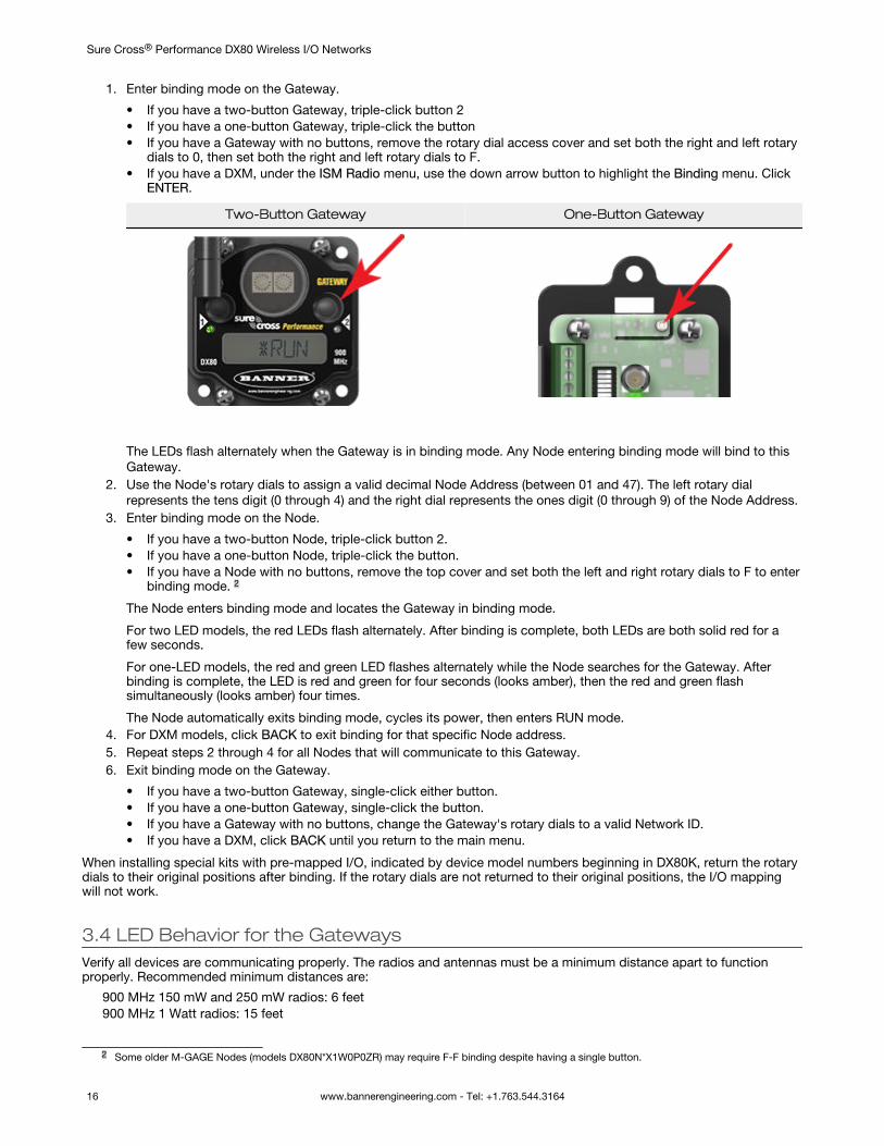
1. Enter binding mode on the Gateway.
• If you have a two-button Gateway, triple-click button 2• If you have a one-button Gateway, triple-click the button• If you have a Gateway with no buttons, remove the rotary dial access cover and set both the right and left rotary
dials to 0, then set both the right and left rotary dials to F.• If you have a DXM, under the ISM Radio menu, use the down arrow button to highlight the Binding menu. Click
ENTER.
Two-Button Gateway One-Button Gateway
The LEDs flash alternately when the Gateway is in binding mode. Any Node entering binding mode will bind to thisGateway.
2. Use the Node's rotary dials to assign a valid decimal Node Address (between 01 and 47). The left rotary dialrepresents the tens digit (0 through 4) and the right dial represents the ones digit (0 through 9) of the Node Address.
3. Enter binding mode on the Node.
• If you have a two-button Node, triple-click button 2.• If you have a one-button Node, triple-click the button.• If you have a Node with no buttons, remove the top cover and set both the left and right rotary dials to F to enter
binding mode. 2
The Node enters binding mode and locates the Gateway in binding mode.
For two LED models, the red LEDs flash alternately. After binding is complete, both LEDs are both solid red for afew seconds.
For one-LED models, the red and green LED flashes alternately while the Node searches for the Gateway. Afterbinding is complete, the LED is red and green for four seconds (looks amber), then the red and green flashsimultaneously (looks amber) four times.
The Node automatically exits binding mode, cycles its power, then enters RUN mode.4. For DXM models, click BACK to exit binding for that specific Node address.5. Repeat steps 2 through 4 for all Nodes that will communicate to this Gateway.6. Exit binding mode on the Gateway.
• If you have a two-button Gateway, single-click either button.• If you have a one-button Gateway, single-click the button.• If you have a Gateway with no buttons, change the Gateway's rotary dials to a valid Network ID.• If you have a DXM, click BACK until you return to the main menu.
When installing special kits with pre-mapped I/O, indicated by device model numbers beginning in DX80K, return the rotarydials to their original positions after binding. If the rotary dials are not returned to their original positions, the I/O mappingwill not work.
3.4 LED Behavior for the GatewaysVerify all devices are communicating properly. The radios and antennas must be a minimum distance apart to functionproperly. Recommended minimum distances are:
900 MHz 150 mW and 250 mW radios: 6 feet900 MHz 1 Watt radios: 15 feet
2 Some older M-GAGE Nodes (models DX80N*X1W0P0ZR) may require F-F binding despite having a single button.
Sure Cross® Performance DX80 Wireless I/O Networks
16 www.bannerengineering.com - Tel: +1.763.544.3164
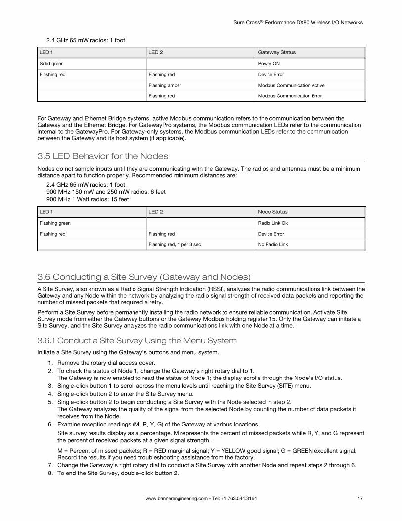
2.4 GHz 65 mW radios: 1 foot
LED 1 LED 2 Gateway Status
Solid green Power ON
Flashing red Flashing red Device Error
Flashing amber Modbus Communication Active
Flashing red Modbus Communication Error
For Gateway and Ethernet Bridge systems, active Modbus communication refers to the communication between theGateway and the Ethernet Bridge. For GatewayPro systems, the Modbus communication LEDs refer to the communicationinternal to the GatewayPro. For Gateway-only systems, the Modbus communication LEDs refer to the communicationbetween the Gateway and its host system (if applicable).
3.5 LED Behavior for the NodesNodes do not sample inputs until they are communicating with the Gateway. The radios and antennas must be a minimumdistance apart to function properly. Recommended minimum distances are:
2.4 GHz 65 mW radios: 1 foot900 MHz 150 mW and 250 mW radios: 6 feet900 MHz 1 Watt radios: 15 feet
LED 1 LED 2 Node Status
Flashing green Radio Link Ok
Flashing red Flashing red Device Error
Flashing red, 1 per 3 sec No Radio Link
3.6 Conducting a Site Survey (Gateway and Nodes)A Site Survey, also known as a Radio Signal Strength Indication (RSSI), analyzes the radio communications link between theGateway and any Node within the network by analyzing the radio signal strength of received data packets and reporting thenumber of missed packets that required a retry.
Perform a Site Survey before permanently installing the radio network to ensure reliable communication. Activate SiteSurvey mode from either the Gateway buttons or the Gateway Modbus holding register 15. Only the Gateway can initiate aSite Survey, and the Site Survey analyzes the radio communications link with one Node at a time.
3.6.1 Conduct a Site Survey Using the Menu SystemInitiate a Site Survey using the Gateway’s buttons and menu system.
1. Remove the rotary dial access cover.2. To check the status of Node 1, change the Gateway’s right rotary dial to 1.
The Gateway is now enabled to read the status of Node 1; the display scrolls through the Node’s I/O status.3. Single-click button 1 to scroll across the menu levels until reaching the Site Survey (SITE) menu.4. Single-click button 2 to enter the Site Survey menu.5. Single-click button 2 to begin conducting a Site Survey with the Node selected in step 2.
The Gateway analyzes the quality of the signal from the selected Node by counting the number of data packets itreceives from the Node.
6. Examine reception readings (M, R, Y, G) of the Gateway at various locations.
Site survey results display as a percentage. M represents the percent of missed packets while R, Y, and G representthe percent of received packets at a given signal strength.
M = Percent of missed packets; R = RED marginal signal; Y = YELLOW good signal; G = GREEN excellent signal.Record the results if you need troubleshooting assistance from the factory.
7. Change the Gateway's right rotary dial to conduct a Site Survey with another Node and repeat steps 2 through 6.8. To end the Site Survey, double-click button 2.
Sure Cross® Performance DX80 Wireless I/O Networks
www.bannerengineering.com - Tel: +1.763.544.3164 17
9. Change the Gateway's right rotary dial back to 0.The LCD displays the device readings for the Gateway.
10. Double-click button 2 to move back to the top level menu.11. Single-click button 1 to return to RUN mode.12. Install the rotary dial access cover, referring to the Installation section of the manual to create an IP67 seal.
Interpreting the Site Survey Results
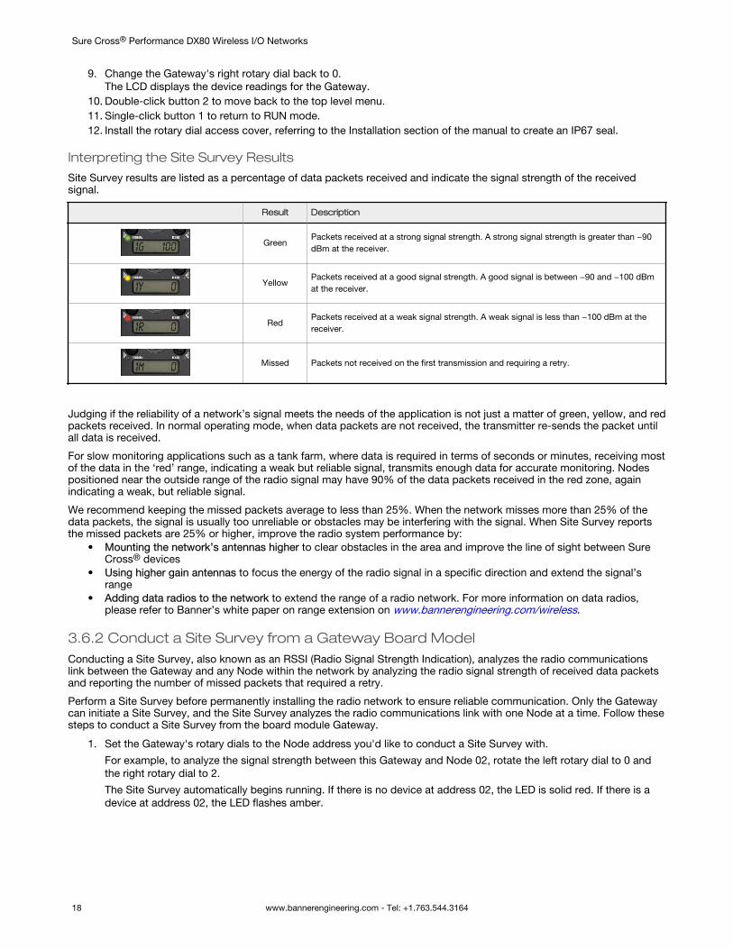
Site Survey results are listed as a percentage of data packets received and indicate the signal strength of the receivedsignal.
Result Description
GreenPackets received at a strong signal strength. A strong signal strength is greater than −90dBm at the receiver.
YellowPackets received at a good signal strength. A good signal is between −90 and −100 dBmat the receiver.
RedPackets received at a weak signal strength. A weak signal is less than −100 dBm at thereceiver.
Missed Packets not received on the first transmission and requiring a retry.
Judging if the reliability of a network’s signal meets the needs of the application is not just a matter of green, yellow, and redpackets received. In normal operating mode, when data packets are not received, the transmitter re-sends the packet untilall data is received.
For slow monitoring applications such as a tank farm, where data is required in terms of seconds or minutes, receiving mostof the data in the ‘red’ range, indicating a weak but reliable signal, transmits enough data for accurate monitoring. Nodespositioned near the outside range of the radio signal may have 90% of the data packets received in the red zone, againindicating a weak, but reliable signal.
We recommend keeping the missed packets average to less than 25%. When the network misses more than 25% of thedata packets, the signal is usually too unreliable or obstacles may be interfering with the signal. When Site Survey reportsthe missed packets are 25% or higher, improve the radio system performance by:
• Mounting the network’s antennas higher to clear obstacles in the area and improve the line of sight between SureCross® devices
• Using higher gain antennas to focus the energy of the radio signal in a specific direction and extend the signal’srange
• Adding data radios to the network to extend the range of a radio network. For more information on data radios,please refer to Banner’s white paper on range extension on www.bannerengineering.com/wireless.
3.6.2 Conduct a Site Survey from a Gateway Board ModelConducting a Site Survey, also known as an RSSI (Radio Signal Strength Indication), analyzes the radio communicationslink between the Gateway and any Node within the network by analyzing the radio signal strength of received data packetsand reporting the number of missed packets that required a retry.
Perform a Site Survey before permanently installing the radio network to ensure reliable communication. Only the Gatewaycan initiate a Site Survey, and the Site Survey analyzes the radio communications link with one Node at a time. Follow thesesteps to conduct a Site Survey from the board module Gateway.
1. Set the Gateway's rotary dials to the Node address you'd like to conduct a Site Survey with.
For example, to analyze the signal strength between this Gateway and Node 02, rotate the left rotary dial to 0 andthe right rotary dial to 2.
The Site Survey automatically begins running. If there is no device at address 02, the LED is solid red. If there is adevice at address 02, the LED flashes amber.
Sure Cross® Performance DX80 Wireless I/O Networks
18 www.bannerengineering.com - Tel: +1.763.544.3164
2. Evaluate the signal strength. The amber LED flashes at specific rates to indicate the Site Survey results. Each signalstrength represents the majority of the data packets being received at that signal strength. For example, a strongsignal strength indicates the majority of the data packets were received at a strong signal, but a few may have beenreceived at a good or weak signal strength.
• Eight flashes per second: Very strong signal strength• Four flashes per second: Strong signal strength• Two flashes per second: Good signal strength• One flash per second: Weak signal strength• Solid amber LED: No radio communication detected
3. To exit the Site Survey, set the Gateway's rotary dials to 00. Otherwise, after 15 minutes the Gateway automaticallyexits Site Survey mode.The LED flashes green to indicate the Gateway is in standard operating mode.
3.6.3 Improving Your Site Survey ResultsRefer to the Sure Cross Installation Guide (p/n 151514) for installation details and tips and tricks for improving your radionetwork's performance.
If your Site Survey results have more yellow than green, consider replacing the Node's antenna with one the following:• Use a 2 dBi Omni dome antenna (model BWA-9O2-D) or a 5 dBi Omni antenna (model BWA-9O5-C)• Use a 6 dBi Yagi (directional) antenna (model BWA-9Y6-A)
If the distance between devices is greater than 5,000 meters (3 miles) line-of-sight or objects, such as trees or man-madeobstructions, interfere with the path, and the MISSED packet count exceeds 25 per 100 packets, consider the followingsteps:
• Install the antenna(s) remotely at a higher position (requires an antenna extension cable);• Use a higher gain antenna;• Decrease the distance between devices; or• Use data radios to extend the position of the Gateway relative to the host system.
Performance Levels
Referenced omni-directional and directional antennas are listed at the end of this section.
Very strong signal strength is 100 green signals (displayed on the LCD) or eight flashes per second (models without LCDs).If the included 2 dBi OMNI antenna does not achieve this signal strength, use a different omni antenna, such as the 2 dBidome antenna (same gain, different form factor) or 5 dBi antenna (higher gain). You may also use a low-gain directionalantenna, such as the 6.5 dBd Yagi antenna.
Strong signal strength is represented by some green signals and some yellow signals (very few red signals and very fewmissed signals) or four flashes per second. To improve your radio performance, consider using a different omni antenna,such as the 2 dBi dome antenna, 5 dBi antenna, 6 dBi antenna, or 8 dBi antenna. You may also use a low-gain directionalantenna, such as the 6.5 dBd Yagi antenna. We also recommend installing the antenna(s) remotely at a higher position.Additional antenna cables are available from Banner Engineering if needed.
Good or weak signal strength equals some yellow signals and a majority of red signals (very few green signals, a smallnumber of yellow signals, and a small to medium number of missed signals) or one to two flashes per second. To improveyour radio performance, consider using one of the 6 dBi or 8 dBi omni-directional antennas or the 10 dBd directionalantenna. We also recommend installing the antenna(s) remotely at a higher position. Additional antenna cables are availablefrom Banner Engineering if needed.
No radio communication is when more than 50% of the radio signals are missed or a solid amber LED. To improve radioperformance, use a 8 dBi omni-direction antenna or a 10 dBd directional antenna and elevate the antenna above anyobstructions. The lack of signals may also be due to the distance between the Gateway (master radio) and Nodes (remoteradio). If this is the case, please contact Banner Engineering for further assistance. We also recommend installing theantenna(s) remotely at a higher position. Additional antenna cables are available from Banner Engineering if needed.
Omni-Directional (Omni) Antennas
BWA-9O2-D (2 dBi OMNI antenna, dome style)—For applications where a durable antenna is needed external to the radioenclosure.
BWA-9O5-C (5 dBi OMNI antenna with RP-SMA connector)—Antenna for medium antenna performance increase or toelevate the antenna above obstacles such as buildings or tall crops. We recommend using one of the following LMR200extension cables (RP-SMA to RP-SMA):
• BWC-2MRSFRS3 (3 meters long)• BWC-2MRSFRS6 (6 meters long)• BWC-2MRSFRS9 (9 meters long)
Sure Cross® Performance DX80 Wireless I/O Networks
www.bannerengineering.com - Tel: +1.763.544.3164 19
• BWC-2MRSFRS12 (12 meters long)
BWA-9O6-AS (6 dBi OMNI antenna with Type N cable connector)— Antenna for strong antenna performance increase.Requires a RP-SMA to Type N converter cable (BWC-1MRSMN05). May require one of the following antenna extensioncables:
• BWC-4MNFN3 (3 meters long)• BWC-4MNFN6 (6 meters long)• BWC-4MNFN15 (15 meters long)• BWC-4MNFN30 (30 meters long)
Requires a surge suppression device (model BWC-LFNBMN-DC) if the antenna is external to a building, connected to otherelectronics, or elevated.
BWA-9O8-AS (8 dBi OMNI antenna with Type N cable connector)—Antenna for very strong antenna performance increase.Requires a RP-SMA to Type N converter cable (model BWC-1MRSMN05). May require one of the following antennaextension cables:
• BWC-4MNFN3 (3 meters long)• BWC-4MNFN6 (6 meters long)• BWC-4MNFN15 (15 meters long)• BWC-4MNFN30 (30 meters long)
Requires a surge suppression device (model BWC-LFNBMN-DC) if the antenna is external to a building, connected to otherelectronics, or elevated.
Directional (Yagi) Antennas
BWA-9Y6-A (6.5 dBd YAGI antenna with Type N cable connector)—Antenna for strong, directional antenna performance.Requires a RP-SMA to Type N converter cable (model BWC-1MRSMN05). May require one of the following antennaextension cables:
• BWC-4MNFN3 (3 meters long)• BWC-4MNFN6 (6 meters long)• BWC-4MNFN15 (15 meters long)• BWC-4MNFN30 (30 meters long)
Requires a surge suppression device (model BWC-LFNBMN-DC) if the antenna is external to a building, connected to otherelectronics, or elevated.
BWA-9Y10-A (10 dBd YAGI antenna with Type N cable connector)—Antenna for very strong, directional antennaperformance increase. Requires a RP-SMA to Type N converter cable (model BWC-1MRSMN05). May requires one of thefollowing antenna extension cables:
• BWC-4MNFN3 (3 meters long)• BWC-4MNFN6 (6 meters long)• BWC-4MNFN15 (15 meters long)• BWC-4MNFN30 (30 meters long)
Requires a surge suppression device (model BWC-LFNBMN-DC) if the antenna is external to a building, connected to otherelectronics, or elevated.
3.6.4 Improving Your Site Survey Results within a MultiHop NetworkIn addition to the information in Improving Your Site Survey Results on page 19, here are some tip and tricks for MultiHopradio networks.
If a repeater radio is available in the network but is not being used, enable the forced routing function on the radio with aweak signal to force it to use a nearby radio with a stronger signal strength. Reference the Banner Engineering documenttitled Forced Routing Method for more information.
If you cannot use forced routing or add a repeater radio to the network, use a 8 dBi omni-direction antenna or a 10 dBddirectional antenna.
We also recommend raising the radio units to a higher elevation, either by physically moving the devices or installing theantenna(s) remotely at a higher position. Additional antenna cables are available from Banner Engineering if needed.
The absent of signals may also be due to the distance between the master (main) and slave (remote) radios. If this is thecase, please contact Banner Engineering for further assistance.
Sure Cross® Performance DX80 Wireless I/O Networks
20 www.bannerengineering.com - Tel: +1.763.544.3164
3.6.5 Additional Information
SITE (Site Survey) Menu
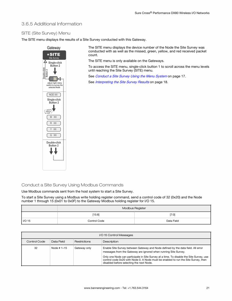
The SITE menu displays the results of a Site Survey conducted with this Gateway.
NOD XX
M XX
R XX
Y XX
G XX
*SITESingle-click
Button 2
Single-click Button 2
Double-click Button 2
adjust right rotary switch to survey the
selected Node
Doub
le-cli
ck
Butto
n 2
AUTO DISPLAY
LOOP
Site Survey
Gateway The SITE menu displays the device number of the Node the Site Survey wasconducted with as well as the missed, green, yellow, and red received packetcount.
The SITE menu is only available on the Gateways.
To access the SITE menu, single-click button 1 to scroll across the menu levelsuntil reaching the Site Survey (SITE) menu.
See Conduct a Site Survey Using the Menu System on page 17.
See Interpreting the Site Survey Results on page 18.
Conduct a Site Survey Using Modbus Commands
Use Modbus commands sent from the host system to start a Site Survey.
To start a Site Survey using a Modbus write holding register command, send a control code of 32 (0x20) and the Nodenumber 1 through 15 (0x01 to 0x0F) to the Gateway Modbus holding register for I/O 15.
Modbus Register
[15:8] [7:0]
I/O 15 Control Code Data Field
I/O 15 Control Messages
Control Code Data Field Restrictions Description
32 Node # 1–15 Gateway only Enable Site Survey between Gateway and Node defined by the data field. All errormessages from the Gateway are ignored when running Site Survey.
Only one Node can participate in Site Survey at a time. To disable the Site Survey, usecontrol code 0x20 with Node 0. A Node must be enabled to run the Site Survey, thendisabled before selecting the next Node.
Sure Cross® Performance DX80 Wireless I/O Networks
www.bannerengineering.com - Tel: +1.763.544.3164 21
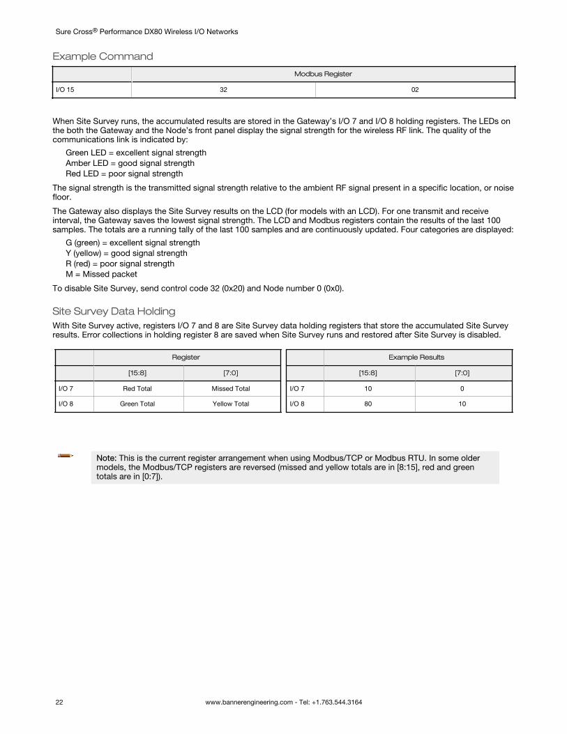
Example Command
Modbus Register
I/O 15 32 02
When Site Survey runs, the accumulated results are stored in the Gateway’s I/O 7 and I/O 8 holding registers. The LEDs onthe both the Gateway and the Node’s front panel display the signal strength for the wireless RF link. The quality of thecommunications link is indicated by:
Green LED = excellent signal strengthAmber LED = good signal strengthRed LED = poor signal strength
The signal strength is the transmitted signal strength relative to the ambient RF signal present in a specific location, or noisefloor.
The Gateway also displays the Site Survey results on the LCD (for models with an LCD). For one transmit and receiveinterval, the Gateway saves the lowest signal strength. The LCD and Modbus registers contain the results of the last 100samples. The totals are a running tally of the last 100 samples and are continuously updated. Four categories are displayed:
G (green) = excellent signal strengthY (yellow) = good signal strengthR (red) = poor signal strengthM = Missed packet
To disable Site Survey, send control code 32 (0x20) and Node number 0 (0x0).
Site Survey Data HoldingWith Site Survey active, registers I/O 7 and 8 are Site Survey data holding registers that store the accumulated Site Surveyresults. Error collections in holding register 8 are saved when Site Survey runs and restored after Site Survey is disabled.
Register
[15:8] [7:0]
I/O 7 Red Total Missed Total
I/O 8 Green Total Yellow Total
Example Results
[15:8] [7:0]
I/O 7 10 0
I/O 8 80 10
Note: This is the current register arrangement when using Modbus/TCP or Modbus RTU. In some oldermodels, the Modbus/TCP registers are reversed (missed and yellow totals are in [8:15], red and greentotals are in [0:7]).
Sure Cross® Performance DX80 Wireless I/O Networks
22 www.bannerengineering.com - Tel: +1.763.544.3164
4 Installing Your Sure Cross® RadiosFollow these recommendations to install your wireless network components.
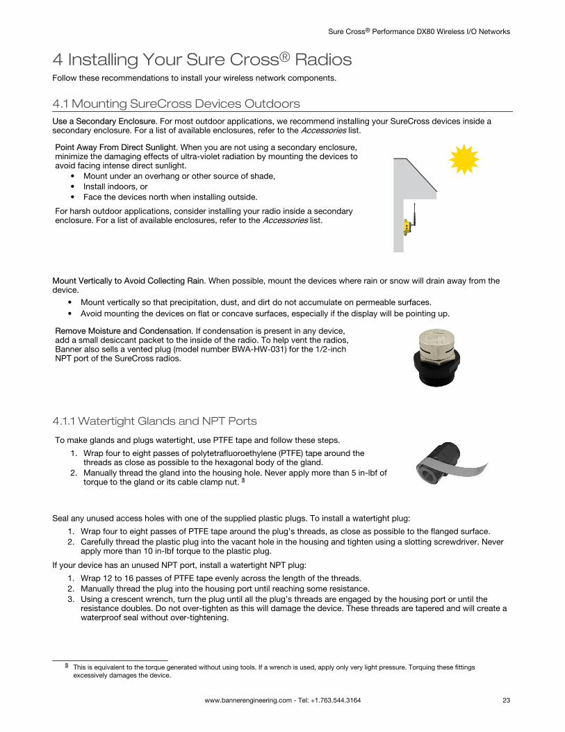
4.1 Mounting SureCross Devices OutdoorsUse a Secondary Enclosure. For most outdoor applications, we recommend installing your SureCross devices inside asecondary enclosure. For a list of available enclosures, refer to the Accessories list.
Point Away From Direct Sunlight. When you are not using a secondary enclosure,minimize the damaging effects of ultra-violet radiation by mounting the devices toavoid facing intense direct sunlight.
• Mount under an overhang or other source of shade,• Install indoors, or• Face the devices north when installing outside.
For harsh outdoor applications, consider installing your radio inside a secondaryenclosure. For a list of available enclosures, refer to the Accessories list.
Mount Vertically to Avoid Collecting Rain. When possible, mount the devices where rain or snow will drain away from thedevice.
• Mount vertically so that precipitation, dust, and dirt do not accumulate on permeable surfaces.• Avoid mounting the devices on flat or concave surfaces, especially if the display will be pointing up.
Remove Moisture and Condensation. If condensation is present in any device,add a small desiccant packet to the inside of the radio. To help vent the radios,Banner also sells a vented plug (model number BWA-HW-031) for the 1/2-inchNPT port of the SureCross radios.
4.1.1 Watertight Glands and NPT Ports
To make glands and plugs watertight, use PTFE tape and follow these steps.
1. Wrap four to eight passes of polytetrafluoroethylene (PTFE) tape around thethreads as close as possible to the hexagonal body of the gland.
2. Manually thread the gland into the housing hole. Never apply more than 5 in-lbf oftorque to the gland or its cable clamp nut. 3
Seal any unused access holes with one of the supplied plastic plugs. To install a watertight plug:
1. Wrap four to eight passes of PTFE tape around the plug’s threads, as close as possible to the flanged surface.2. Carefully thread the plastic plug into the vacant hole in the housing and tighten using a slotting screwdriver. Never
apply more than 10 in-lbf torque to the plastic plug.
If your device has an unused NPT port, install a watertight NPT plug:
1. Wrap 12 to 16 passes of PTFE tape evenly across the length of the threads.2. Manually thread the plug into the housing port until reaching some resistance.3. Using a crescent wrench, turn the plug until all the plug’s threads are engaged by the housing port or until the
resistance doubles. Do not over-tighten as this will damage the device. These threads are tapered and will create awaterproof seal without over-tightening.
3 This is equivalent to the torque generated without using tools. If a wrench is used, apply only very light pressure. Torquing these fittingsexcessively damages the device.
Sure Cross® Performance DX80 Wireless I/O Networks
www.bannerengineering.com - Tel: +1.763.544.3164 23
4.2 Other Installation Requirements
4.2 Reduce Chemical ExposureBefore installing any devices in a chemically harsh environment, contact the manufacturer for more information regardingthe life-expectancy. Solvents, oxidizing agents, and other chemicals will damage the devices.
4.2 Minimize Mechanical StressAlthough these radio devices are very durable, they are sophisticated electronic devices that are sensitive to shock andexcessive loading.
• Avoid mounting the devices to an object that may be shifting or vibrating excessively. High levels of static force oracceleration may damage the housing or electronic components.
• Do not subject the devices to external loads. Do not step on them or use them as handgrips.• Do not allow long lengths of cable to hang from the glands on the Gateway or Node. Cabling heavier than 100
grams should be supported instead of allowed to hang from the housing.• Do not crack the housing by over-tightening the top screws. Do not exceed the maximum torque of 4 in-lbf.
It is the user’s responsibility to install these devices so they will not be subject to over-voltage transients. Always ground thedevices in accordance with local, state, or national regulations.
4.2 When Installing Performance or MultiHop 1-Watt RadiosNotice: This equipment must be professionally installed. The output power must be limited, through the use of firmware or ahardware attenuator, when using high-gain antennas such that the +36 dBm EIRP limit is not exceeded.
4.3 Installation Quick TipsThe following are some quick tips for improving the installation of wireless network components.
4.3.1 Create a Clear Communication PathWireless communication is hindered by radio interference and obstructions in the path between the transmitter andreceiver. To achieve the best radio performance, carefully consider the installation locations for the Gateways and Nodesand select locations without obstructions in the path.
For more information about antennas, please refer to the Antenna Basics reference guide, Banner document p/n 132113.
4.3.2 Increase the Height of the AntennasPosition the external antenna vertically for optimal RF communication. If necessary, consider changing the height of theSure Cross radio, or its antenna, to improve reception. For outdoor applications, mounting the antenna on top of a buildingor pole may help achieve a line-of-sight radio link with the other radios in the network.
No line of sight
Line of sight
Node
Gateway
Sure Cross® Performance DX80 Wireless I/O Networks
24 www.bannerengineering.com - Tel: +1.763.544.3164
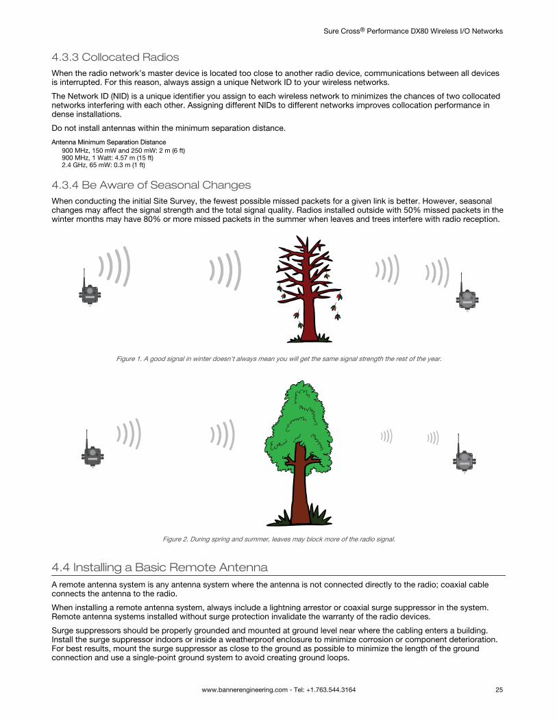
4.3.3 Collocated RadiosWhen the radio network’s master device is located too close to another radio device, communications between all devicesis interrupted. For this reason, always assign a unique Network ID to your wireless networks.
The Network ID (NID) is a unique identifier you assign to each wireless network to minimizes the chances of two collocatednetworks interfering with each other. Assigning different NIDs to different networks improves collocation performance indense installations.
Do not install antennas within the minimum separation distance.
Antenna Minimum Separation Distance900 MHz, 150 mW and 250 mW: 2 m (6 ft)900 MHz, 1 Watt: 4.57 m (15 ft)2.4 GHz, 65 mW: 0.3 m (1 ft)
4.3.4 Be Aware of Seasonal ChangesWhen conducting the initial Site Survey, the fewest possible missed packets for a given link is better. However, seasonalchanges may affect the signal strength and the total signal quality. Radios installed outside with 50% missed packets in thewinter months may have 80% or more missed packets in the summer when leaves and trees interfere with radio reception.
Figure 1. A good signal in winter doesn't always mean you will get the same signal strength the rest of the year.
Figure 2. During spring and summer, leaves may block more of the radio signal.
4.4 Installing a Basic Remote AntennaA remote antenna system is any antenna system where the antenna is not connected directly to the radio; coaxial cableconnects the antenna to the radio.
When installing a remote antenna system, always include a lightning arrestor or coaxial surge suppressor in the system.Remote antenna systems installed without surge protection invalidate the warranty of the radio devices.
Surge suppressors should be properly grounded and mounted at ground level near where the cabling enters a building.Install the surge suppressor indoors or inside a weatherproof enclosure to minimize corrosion or component deterioration.For best results, mount the surge suppressor as close to the ground as possible to minimize the length of the groundconnection and use a single-point ground system to avoid creating ground loops.
Sure Cross® Performance DX80 Wireless I/O Networks
www.bannerengineering.com - Tel: +1.763.544.3164 25
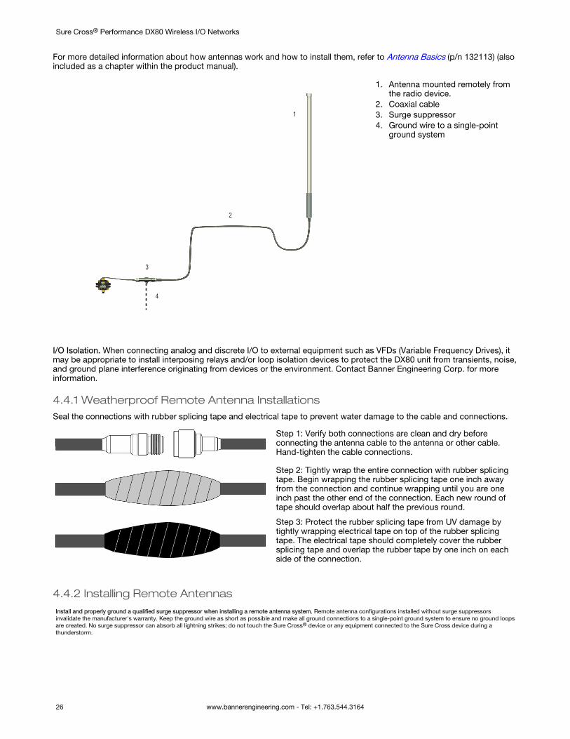
For more detailed information about how antennas work and how to install them, refer to Antenna Basics (p/n 132113) (alsoincluded as a chapter within the product manual).
1
2
3
4
1. Antenna mounted remotely fromthe radio device.
2. Coaxial cable3. Surge suppressor4. Ground wire to a single-point
ground system
I/O Isolation. When connecting analog and discrete I/O to external equipment such as VFDs (Variable Frequency Drives), itmay be appropriate to install interposing relays and/or loop isolation devices to protect the DX80 unit from transients, noise,and ground plane interference originating from devices or the environment. Contact Banner Engineering Corp. for moreinformation.
4.4.1 Weatherproof Remote Antenna InstallationsSeal the connections with rubber splicing tape and electrical tape to prevent water damage to the cable and connections.
Step 1: Verify both connections are clean and dry beforeconnecting the antenna cable to the antenna or other cable.Hand-tighten the cable connections.
Step 2: Tightly wrap the entire connection with rubber splicingtape. Begin wrapping the rubber splicing tape one inch awayfrom the connection and continue wrapping until you are oneinch past the other end of the connection. Each new round oftape should overlap about half the previous round.
Step 3: Protect the rubber splicing tape from UV damage bytightly wrapping electrical tape on top of the rubber splicingtape. The electrical tape should completely cover the rubbersplicing tape and overlap the rubber tape by one inch on eachside of the connection.
4.4.2 Installing Remote AntennasInstall and properly ground a qualified surge suppressor when installing a remote antenna system. Remote antenna configurations installed without surge suppressorsinvalidate the manufacturer's warranty. Keep the ground wire as short as possible and make all ground connections to a single-point ground system to ensure no ground loopsare created. No surge suppressor can absorb all lightning strikes; do not touch the Sure Cross® device or any equipment connected to the Sure Cross device during athunderstorm.
Sure Cross® Performance DX80 Wireless I/O Networks
26 www.bannerengineering.com - Tel: +1.763.544.3164
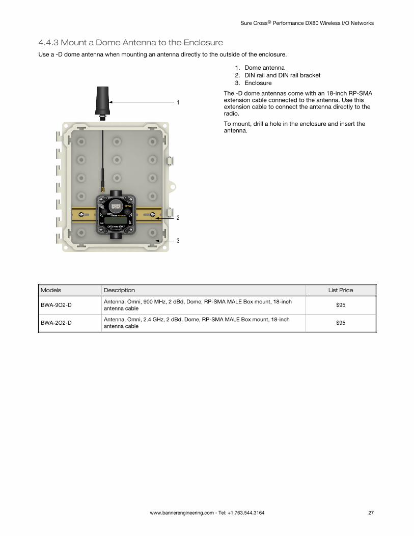
4.4.3 Mount a Dome Antenna to the EnclosureUse a -D dome antenna when mounting an antenna directly to the outside of the enclosure.
1
3
2
1. Dome antenna2. DIN rail and DIN rail bracket3. Enclosure
The -D dome antennas come with an 18-inch RP-SMAextension cable connected to the antenna. Use thisextension cable to connect the antenna directly to theradio.
To mount, drill a hole in the enclosure and insert theantenna.
Models Description List Price
BWA-9O2-DAntenna, Omni, 900 MHz, 2 dBd, Dome, RP-SMA MALE Box mount, 18-inchantenna cable
$95
BWA-2O2-DAntenna, Omni, 2.4 GHz, 2 dBd, Dome, RP-SMA MALE Box mount, 18-inchantenna cable
$95
Sure Cross® Performance DX80 Wireless I/O Networks
www.bannerengineering.com - Tel: +1.763.544.3164 27
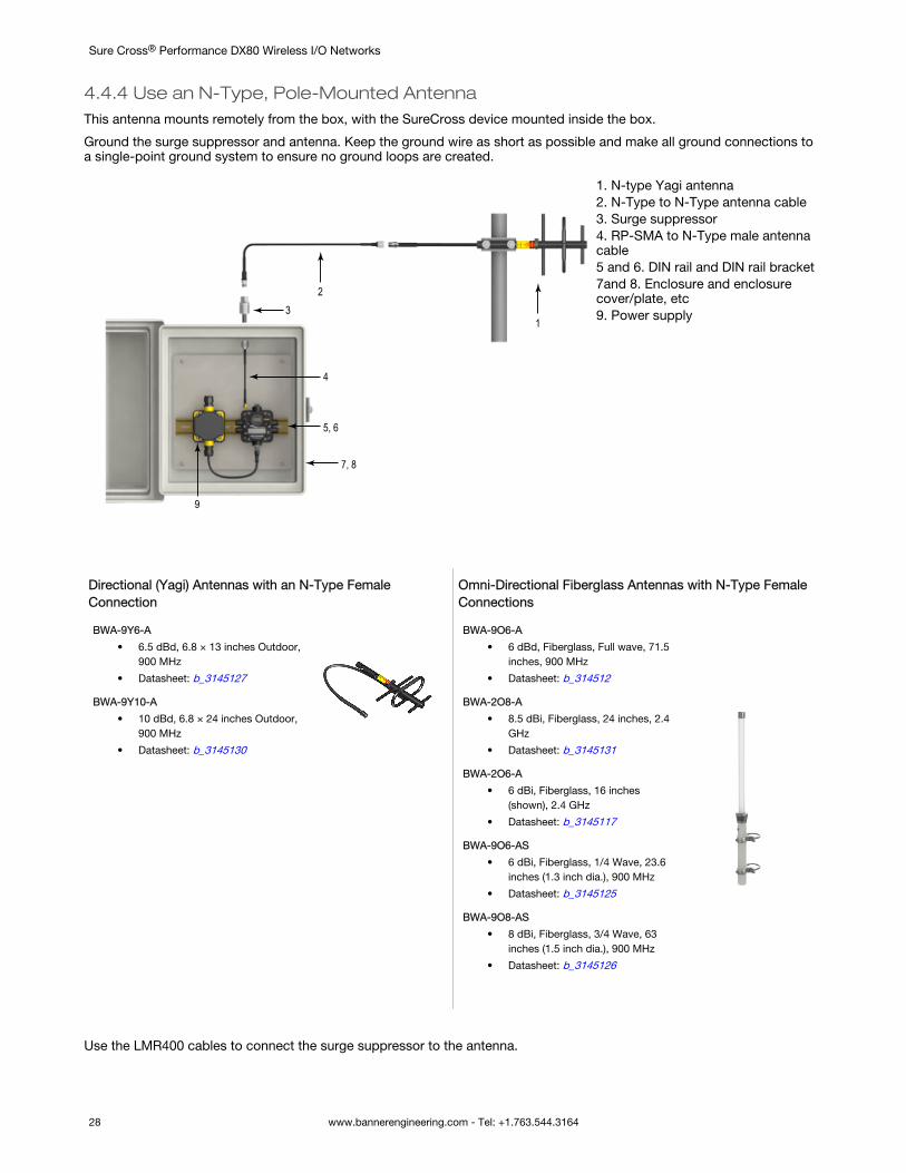
4.4.4 Use an N-Type, Pole-Mounted AntennaThis antenna mounts remotely from the box, with the SureCross device mounted inside the box.
Ground the surge suppressor and antenna. Keep the ground wire as short as possible and make all ground connections toa single-point ground system to ensure no ground loops are created.
13
4
5, 6
2
7, 8
9
1. N-type Yagi antenna2. N-Type to N-Type antenna cable3. Surge suppressor4. RP-SMA to N-Type male antennacable5 and 6. DIN rail and DIN rail bracket7and 8. Enclosure and enclosurecover/plate, etc9. Power supply
Directional (Yagi) Antennas with an N-Type FemaleConnection
BWA-9Y6-A
• 6.5 dBd, 6.8 × 13 inches Outdoor,900 MHz
• Datasheet: b_3145127
BWA-9Y10-A
• 10 dBd, 6.8 × 24 inches Outdoor,900 MHz
• Datasheet: b_3145130
Omni-Directional Fiberglass Antennas with N-Type FemaleConnections
BWA-9O6-A
• 6 dBd, Fiberglass, Full wave, 71.5inches, 900 MHz
• Datasheet: b_314512
BWA-2O8-A
• 8.5 dBi, Fiberglass, 24 inches, 2.4GHz
• Datasheet: b_3145131
BWA-2O6-A
• 6 dBi, Fiberglass, 16 inches(shown), 2.4 GHz
• Datasheet: b_3145117
BWA-9O6-AS
• 6 dBi, Fiberglass, 1/4 Wave, 23.6inches (1.3 inch dia.), 900 MHz
• Datasheet: b_3145125
BWA-9O8-AS
• 8 dBi, Fiberglass, 3/4 Wave, 63inches (1.5 inch dia.), 900 MHz
• Datasheet: b_3145126
Use the LMR400 cables to connect the surge suppressor to the antenna.
Sure Cross® Performance DX80 Wireless I/O Networks
28 www.bannerengineering.com - Tel: +1.763.544.3164
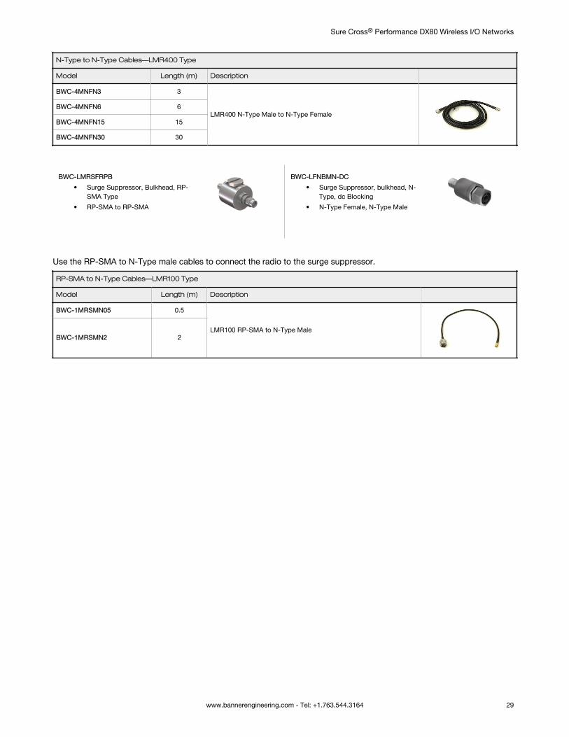
N-Type to N-Type Cables—LMR400 Type
Model Length (m) Description
BWC-4MNFN3 3
LMR400 N-Type Male to N-Type FemaleBWC-4MNFN6 6
BWC-4MNFN15 15
BWC-4MNFN30 30
BWC-LMRSFRPB
• Surge Suppressor, Bulkhead, RP-SMA Type
• RP-SMA to RP-SMA
BWC-LFNBMN-DC
• Surge Suppressor, bulkhead, N-Type, dc Blocking
• N-Type Female, N-Type Male
Use the RP-SMA to N-Type male cables to connect the radio to the surge suppressor.
RP-SMA to N-Type Cables—LMR100 Type
Model Length (m) Description
BWC-1MRSMN05 0.5
LMR100 RP-SMA to N-Type MaleBWC-1MRSMN2 2
Sure Cross® Performance DX80 Wireless I/O Networks
www.bannerengineering.com - Tel: +1.763.544.3164 29
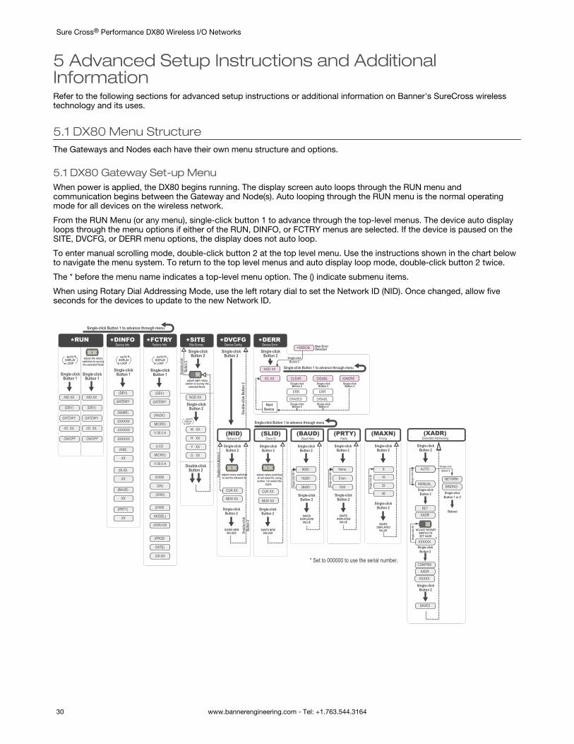
5 Advanced Setup Instructions and AdditionalInformationRefer to the following sections for advanced setup instructions or additional information on Banner's SureCross wirelesstechnology and its uses.
5.1 DX80 Menu StructureThe Gateways and Nodes each have their own menu structure and options.
5.1 DX80 Gateway Set-up MenuWhen power is applied, the DX80 begins running. The display screen auto loops through the RUN menu andcommunication begins between the Gateway and Node(s). Auto looping through the RUN menu is the normal operatingmode for all devices on the wireless network.
From the RUN Menu (or any menu), single-click button 1 to advance through the top-level menus. The device auto displayloops through the menu options if either of the RUN, DINFO, or FCTRY menus are selected. If the device is paused on theSITE, DVCFG, or DERR menu options, the display does not auto loop.
To enter manual scrolling mode, double-click button 2 at the top level menu. Use the instructions shown in the chart belowto navigate the menu system. To return to the top level menus and auto display loop mode, double-click button 2 twice.
The * before the menu name indicates a top-level menu option. The () indicate submenu items.
When using Rotary Dial Addressing Mode, use the left rotary dial to set the Network ID (NID). Once changed, allow fiveseconds for the devices to update to the new Network ID.
NOD XX
M XX
R XX
Y XX
G XX
*DINFO *FCTRY *SITE *DVCFG *DERR*RUN
AUTO DISPLAY
LOOP
AUTO DISPLAY
LOOP
AUTO DISPLAY
LOOP
(DEV)
GATEWY
(NID)
XX
(SLID)
XX
(BAUD)
XX
(PRTY)
XX
(DEV)
GATEWY
(RADIO
MICRO)
V 00.0 A
(LCD
MICRO)
V 00.0 A
(DX80
S/N)
(0000)
(DX80
MODEL)
(0000-00)
(PROD
DATE)
(00-00)
Single-click Button 2
Single-click Button 2
Single-click Button 2
Double-click Button 2
adjust right rotary switch to survey the
selected Node
Single-click Button 2
Doub
le-cli
ck
Butto
n 2
Doub
le-cli
ck B
utto
n 2
NOD XX
EC XX CLEAR
ERR
ERASED
ERR
DISABL
*ERROR
DISABL IGNORE
Next Device
Single-click Button 1 to advance through menu
AUTO DISPLAY
LOOP
Single-click Button 2
Single-click Button 2
Single-click Button 2
Single-click Button 2
Single-click Button 2
Single-click Button 2
New Error Detected
adjust the rotary switches to survey the selected Node
(DEV)
I/O XX
GATEWY
NID XX
ON/OFF
(DEV)
I/O XX
GATEWY
NID XX
ON/OFF
Even
None
Odd
Single-click Button 2
Single-click Button 2
SAVES DISPLAYED
VALUE
Sing
le-cli
ck B
1
19200
9600
38400
Single-click Button 2
Single-click Button 2
SAVES DISPLAYED
VALUE
NEW XX
Single-click Button 2
Single-click Button 2
adjust rotary switchesto set the network ID
SAVES NEW VALUES
CUR XX
Single-click Button 2
Single-click Button 2
adjust rotary switchesto set slave ID, usingbutton 1 to select the
digits
SAVES NEW VALUES
(NID) (SLID) (BAUD) (PRTY)Network ID Slave ID Baud Rate Parity
Sing
le-cli
ck B
1
NEW XX
Single-click Button 1
Single-click Button 1
Single-click Button 1
Single-click Button 1
Single-click Button 1 to advance through menu
(NAME)
XXXXXX
XXXXXX
Single-click Button 1 to advance through menu
CUR XX
Doub
le-cli
ck B
utto
n 2
Doub
le-cli
ck
Butto
n 2
* Set to 000000 to use the serial number.
Device Info Factory Info Site Survey Device Config Device Error
16
8
32
Single-click Button 2
Single-click Button 2
SAVES DISPLAYED
VALUE
Sing
le-cli
ck B
1
(MAXN)Timing
48
MANUAL
AUTOAUTO
SET
Single-click Button 2
Single-click Button 2
Sing
le-cli
ck B
1
(XADR)Extended Addressing
XADR
ADJUST ROTARY SWITCH TOSET XADR
Single-click Button 2
XXXXXX
Sing
le-cli
ck B
1
Single-click Button 2
CONFRM
XADR
XXXXX
NETWRK
Single-clickButton 2
BINDNGSingle-click
Button 1 or 2
Reboot
SAVED
*
XXXXXX
Sure Cross® Performance DX80 Wireless I/O Networks
30 www.bannerengineering.com - Tel: +1.763.544.3164
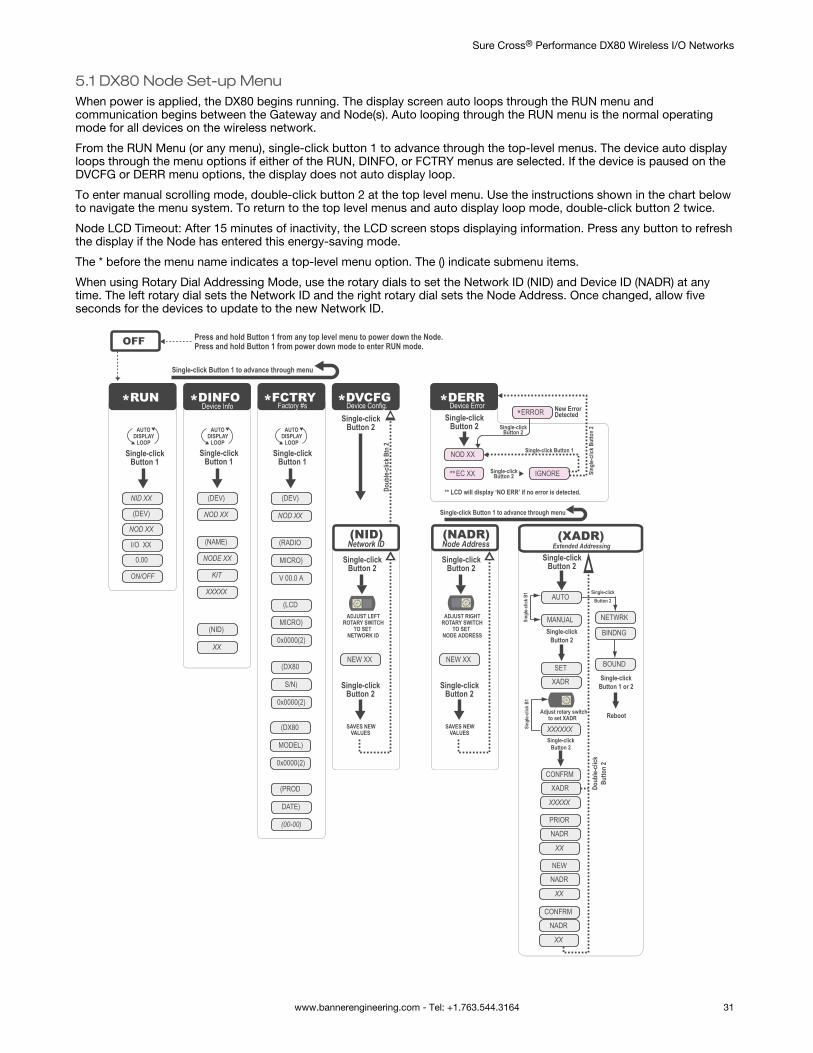
5.1 DX80 Node Set-up MenuWhen power is applied, the DX80 begins running. The display screen auto loops through the RUN menu andcommunication begins between the Gateway and Node(s). Auto looping through the RUN menu is the normal operatingmode for all devices on the wireless network.
From the RUN Menu (or any menu), single-click button 1 to advance through the top-level menus. The device auto displayloops through the menu options if either of the RUN, DINFO, or FCTRY menus are selected. If the device is paused on theDVCFG or DERR menu options, the display does not auto display loop.
To enter manual scrolling mode, double-click button 2 at the top level menu. Use the instructions shown in the chart belowto navigate the menu system. To return to the top level menus and auto display loop mode, double-click button 2 twice.
Node LCD Timeout: After 15 minutes of inactivity, the LCD screen stops displaying information. Press any button to refreshthe display if the Node has entered this energy-saving mode.
The * before the menu name indicates a top-level menu option. The () indicate submenu items.
When using Rotary Dial Addressing Mode, use the rotary dials to set the Network ID (NID) and Device ID (NADR) at anytime. The left rotary dial sets the Network ID and the right rotary dial sets the Node Address. Once changed, allow fiveseconds for the devices to update to the new Network ID.
*DINFO*RUN *FCTRY *DVCFG *DERR
AUTO DISPLAY
LOOP
AUTO DISPLAY
LOOP
AUTO DISPLAY
LOOP
(DEV)
NOD XX
(NAME)
NODE XX
KIT
XXXXX
(NID)
XX
(DEV)
NOD XX
(RADIO
MICRO)
V 00.0 A
(DX80
S/N)
0x0000(2)
(LCD
MICRO)
0x0000(2)
(PROD
DATE)
(00-00)
Single-click Button 2
NEW XX
Single-click Button 2
Single-click Button 2
SAVES NEW VALUES
(NID)Network ID
Single-click Button 2
Doub
le-cli
ck B
tn 2
NEW XX
Single-click Button 2
Single-click Button 2
SAVES NEW VALUES
(NADR)Node Address
NOD XX
**EC XX IGNORE
*ERROR
Single-click Button 1
** LCD will display ‘NO ERR’ if no error is detected.
Single-click Button 2
Single-click Button 2
New Error Detected
Sing
le-cli
ck B
utto
n 2
OFF Press and hold Button 1 from any top level menu to power down the Node.Press and hold Button 1 from power down mode to enter RUN mode.
ADJUST LEFT ROTARY SWITCH
TO SET NETWORK ID
ADJUST RIGHT ROTARY SWITCH
TO SET NODE ADDRESS
(DEV)
I/O XX
NOD XX
NID XX
ON/OFF
Single-click Button 1
Single-click Button 1
Single-click Button 1
(DX80
MODEL)
0x0000(2)
0.00
Single-click Button 1 to advance through menu
MANUAL
AUTO
SET
Single-click Button 2
Sing
le-cli
ck B
1
(XADR)Extended Addressing
XADR
Adjust rotary switch to set XADR
Single-click Button 2
XXXXXXSing
le-cli
ck B
1
CONFRM
XADR
XXXXX
NETWRK
Single-clickButton 2
BINDNG
Single-click Button 1 or 2
Reboot
Doub
le-cli
ck
Butto
n 2
BOUND
Device Info Factory #s Device Config. Device Error
Single-clickButton 2
PRIOR
NADR
XX
NEW
NADR
XX
CONFRM
NADR
XX
Single-click Button 1 to advance through menu
Sure Cross® Performance DX80 Wireless I/O Networks
www.bannerengineering.com - Tel: +1.763.544.3164 31
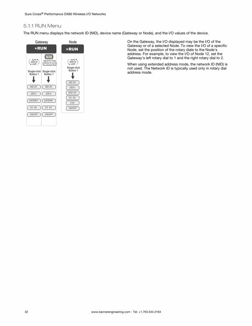
5.1.1 RUN MenuThe RUN menu displays the network ID (NID), device name (Gateway or Node), and the I/O values of the device.
*RUN
AUTO DISPLAY
LOOPadjust the rotary
switches to survey the selected Node
(DEV)
I/O XX
GATEWY
NID XX
ON/OFF
(DEV)
I/O XX
GATEWY
NID XX
ON/OFF
Single-click Button 1
Single-click Button 1
*RUN
AUTO DISPLAY
LOOP
(DEV)
I/O XX
NOD XX
NID XX
ON/OFF
Single-click Button 1
0.00
Gateway Node On the Gateway, the I/O displayed may be the I/O of theGateway or of a selected Node. To view the I/O of a specificNode, set the position of the rotary dials to the Node'saddress. For example, to view the I/O of Node 12, set theGateway's left rotary dial to 1 and the right rotary dial to 2.
When using extended address mode, the network ID (NID) isnot used. The Network ID is typically used only in rotary dialaddress mode.
Sure Cross® Performance DX80 Wireless I/O Networks
32 www.bannerengineering.com - Tel: +1.763.544.3164
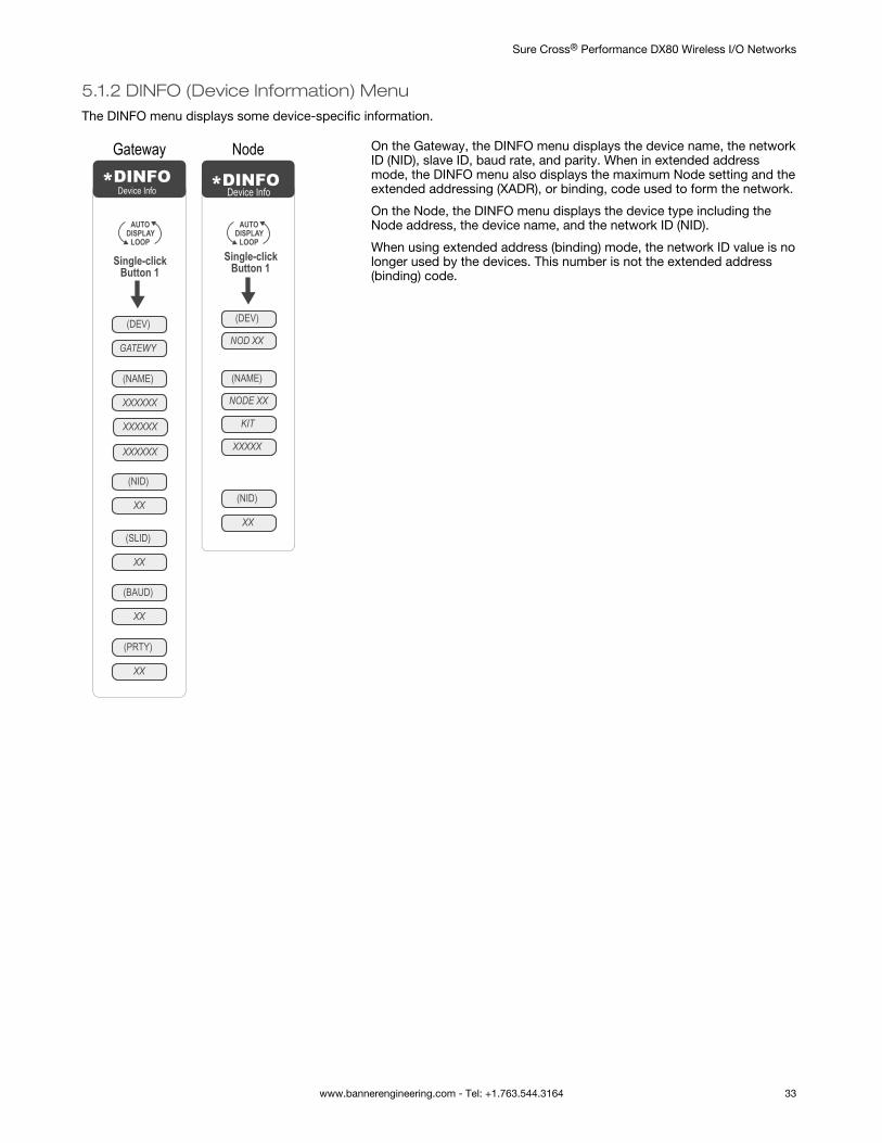
5.1.2 DINFO (Device Information) MenuThe DINFO menu displays some device-specific information.
*DINFO
AUTO DISPLAY
LOOP
(DEV)
GATEWY
(NID)
XX
(SLID)
XX
(BAUD)
XX
(PRTY)
XX
Single-click Button 1
(NAME)
XXXXXX
XXXXXX
Device Info
XXXXXX
*DINFO
AUTO DISPLAY
LOOP
(DEV)
NOD XX
(NAME)
NODE XX
KIT
XXXXX
(NID)
XX
Single-click Button 1
Device Info
Gateway Node On the Gateway, the DINFO menu displays the device name, the networkID (NID), slave ID, baud rate, and parity. When in extended addressmode, the DINFO menu also displays the maximum Node setting and theextended addressing (XADR), or binding, code used to form the network.
On the Node, the DINFO menu displays the device type including theNode address, the device name, and the network ID (NID).
When using extended address (binding) mode, the network ID value is nolonger used by the devices. This number is not the extended address(binding) code.
Sure Cross® Performance DX80 Wireless I/O Networks
www.bannerengineering.com - Tel: +1.763.544.3164 33
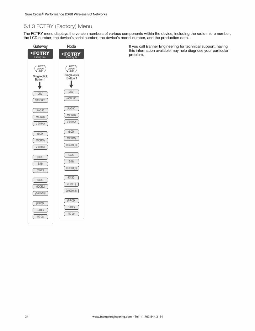
5.1.3 FCTRY (Factory) MenuThe FCTRY menu displays the version numbers of various components within the device, including the radio micro number,the LCD number, the device’s serial number, the device’s model number, and the production date.
*FCTRY
AUTO DISPLAY
LOOP
(DEV)
GATEWY
(RADIO
MICRO)
V 00.0 A
(LCD
MICRO)
V 00.0 A
(DX80
S/N)
(0000)
(DX80
MODEL)
(0000-00)
(PROD
DATE)
(00-00)
Single-click Button 1
Factory Info *FCTRY
AUTO DISPLAY
LOOP
(DEV)
NOD XX
(RADIO
MICRO)
V 00.0 A
(DX80
S/N)
0x0000(2)
(LCD
MICRO)
0x0000(2)
(PROD
DATE)
(00-00)
Single-click Button 1
(DX80
MODEL)
0x0000(2)
Factory #s
Gateway Node If you call Banner Engineering for technical support, havingthis information available may help diagnose your particularproblem.
Sure Cross® Performance DX80 Wireless I/O Networks
34 www.bannerengineering.com - Tel: +1.763.544.3164
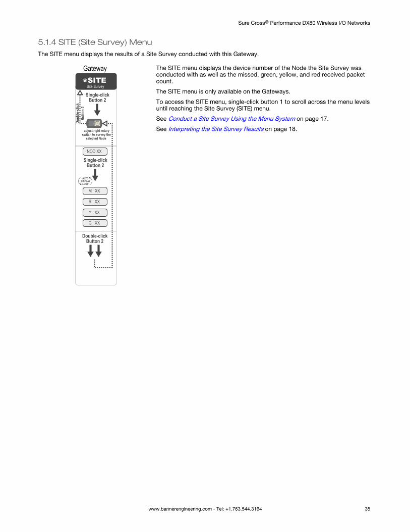
5.1.4 SITE (Site Survey) MenuThe SITE menu displays the results of a Site Survey conducted with this Gateway.
NOD XX
M XX
R XX
Y XX
G XX
*SITESingle-click
Button 2
Single-click Button 2
Double-click Button 2
adjust right rotary switch to survey the
selected Node
Doub
le-cli
ck
Butto
n 2
AUTO DISPLAY
LOOP
Site Survey
Gateway The SITE menu displays the device number of the Node the Site Survey wasconducted with as well as the missed, green, yellow, and red received packetcount.
The SITE menu is only available on the Gateways.
To access the SITE menu, single-click button 1 to scroll across the menu levelsuntil reaching the Site Survey (SITE) menu.
See Conduct a Site Survey Using the Menu System on page 17.
See Interpreting the Site Survey Results on page 18.
Sure Cross® Performance DX80 Wireless I/O Networks
www.bannerengineering.com - Tel: +1.763.544.3164 35
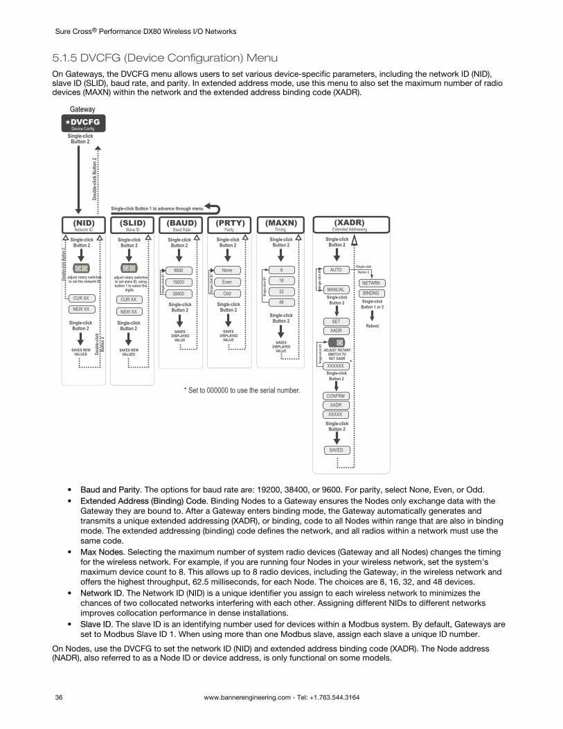
5.1.5 DVCFG (Device Configuration) MenuOn Gateways, the DVCFG menu allows users to set various device-specific parameters, including the network ID (NID),slave ID (SLID), baud rate, and parity. In extended address mode, use this menu to also set the maximum number of radiodevices (MAXN) within the network and the extended address binding code (XADR).
*DVCFGSingle-click
Button 2
Doub
le-cli
ck B
utto
n 2
Even
None
Odd
Single-click Button 2
Single-click Button 2
SAVES DISPLAYED
VALUE
Sing
le-cli
ck B
1
19200
9600
38400
Single-click Button 2
Single-click Button 2
SAVES DISPLAYED
VALUE
NEW XX
Single-click Button 2
Single-click Button 2
adjust rotary switchesto set the network ID
SAVES NEW VALUES
CUR XX
Single-click Button 2
Single-click Button 2
adjust rotary switchesto set slave ID, usingbutton 1 to select the
digits
SAVES NEW VALUES
(NID) (SLID) (BAUD) (PRTY)Network ID Slave ID Baud Rate Parity
Sing
le-cli
ck B
1
NEW XX
Single-click Button 1 to advance through menu
CUR XX
Doub
le-cli
ck B
utto
n 2
Doub
le-cli
ck
Butto
n 2
* Set to 000000 to use the serial number.
Device Config
16
8
32
Single-click Button 2
Single-click Button 2
SAVES DISPLAYED
VALUE
Sing
le-cli
ck B
1
(MAXN)Timing
48
MANUAL
AUTOAUTO
SET
Single-click Button 2
Single-click Button 2
Sing
le-cli
ck B
1
(XADR)Extended Addressing
XADR
ADJUST ROTARY SWITCH TOSET XADR
Single-click Button 2
XXXXXX
Sing
le-cli
ck B
1
Single-click Button 2
CONFRM
XADR
XXXXX
NETWRK
Single-clickButton 2
BINDNGSingle-click
Button 1 or 2
Reboot
SAVED
*
Gateway
• Baud and Parity. The options for baud rate are: 19200, 38400, or 9600. For parity, select None, Even, or Odd.• Extended Address (Binding) Code. Binding Nodes to a Gateway ensures the Nodes only exchange data with the
Gateway they are bound to. After a Gateway enters binding mode, the Gateway automatically generates andtransmits a unique extended addressing (XADR), or binding, code to all Nodes within range that are also in bindingmode. The extended addressing (binding) code defines the network, and all radios within a network must use thesame code.
• Max Nodes. Selecting the maximum number of system radio devices (Gateway and all Nodes) changes the timingfor the wireless network. For example, if you are running four Nodes in your wireless network, set the system'smaximum device count to 8. This allows up to 8 radio devices, including the Gateway, in the wireless network andoffers the highest throughput, 62.5 milliseconds, for each Node. The choices are 8, 16, 32, and 48 devices.
• Network ID. The Network ID (NID) is a unique identifier you assign to each wireless network to minimizes thechances of two collocated networks interfering with each other. Assigning different NIDs to different networksimproves collocation performance in dense installations.
• Slave ID. The slave ID is an identifying number used for devices within a Modbus system. By default, Gateways areset to Modbus Slave ID 1. When using more than one Modbus slave, assign each slave a unique ID number.
On Nodes, use the DVCFG to set the network ID (NID) and extended address binding code (XADR). The Node address(NADR), also referred to as a Node ID or device address, is only functional on some models.
Sure Cross® Performance DX80 Wireless I/O Networks
36 www.bannerengineering.com - Tel: +1.763.544.3164
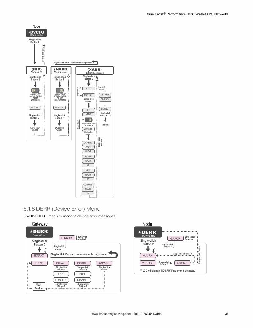
*DVCFG
NEW XX
Single-click Button 2
Single-click Button 2
SAVES NEW VALUES
(NID)Network ID
Single-click Button 2
Doub
le-cli
ck B
tn 2
NEW XX
Single-click Button 2
Single-click Button 2
SAVES NEW VALUES
(NADR)Node Address
ADJUST LEFT ROTARY SWITCH
TO SET NETWORK ID
ADJUST RIGHT ROTARY SWITCH
TO SET NODE ADDRESS
MANUAL
AUTO
SET
Single-click Button 2
Sing
le-cli
ck B
1
(XADR)Extended Addressing
XADR
Adjust rotary switch to set XADR
Single-click Button 2
XXXXXXSing
le-cli
ck B
1
CONFRM
XADR
XXXXX
NETWRK
Single-clickButton 2
BINDNG
Single-click Button 1 or 2
Reboot
Doub
le-cli
ck
Butto
n 2
BOUND
Device Config.
Single-clickButton 2
PRIOR
NADR
XX
NEW
NADR
XX
CONFRM
NADR
XX
Single-click Button 1 to advance through menu
Node
5.1.6 DERR (Device Error) MenuUse the DERR menu to manage device error messages.
*DERRSingle-click
Button 2
NOD XX
EC XX CLEAR
ERR
ERASED
ERR
DISABL
*ERROR
DISABL IGNORE
Next Device
Single-click Button 1 to advance through menu
Single-click Button 2
Single-click Button 2
Single-click Button 2
Single-click Button 2
Single-click Button 2
Single-click Button 2
New Error Detected
Device Error *DERRSingle-click
Button 2
NOD XX
**EC XX IGNORE
*ERROR
Single-click Button 1
** LCD will display ‘NO ERR’ if no error is detected.
Single-click Button 2
Single-click Button 2
New Error Detected
Sing
le-cli
ck B
utto
n 2
Device Error
Gateway Node
Sure Cross® Performance DX80 Wireless I/O Networks
www.bannerengineering.com - Tel: +1.763.544.3164 37
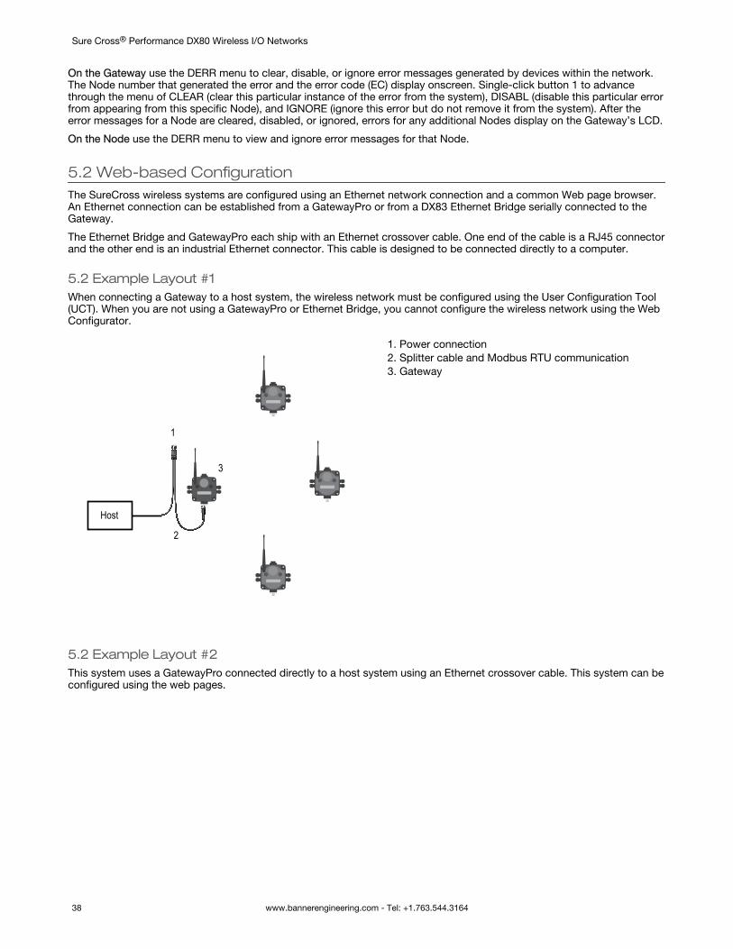
On the Gateway use the DERR menu to clear, disable, or ignore error messages generated by devices within the network.The Node number that generated the error and the error code (EC) display onscreen. Single-click button 1 to advancethrough the menu of CLEAR (clear this particular instance of the error from the system), DISABL (disable this particular errorfrom appearing from this specific Node), and IGNORE (ignore this error but do not remove it from the system). After theerror messages for a Node are cleared, disabled, or ignored, errors for any additional Nodes display on the Gateway’s LCD.
On the Node use the DERR menu to view and ignore error messages for that Node.
5.2 Web-based ConfigurationThe SureCross wireless systems are configured using an Ethernet network connection and a common Web page browser.An Ethernet connection can be established from a GatewayPro or from a DX83 Ethernet Bridge serially connected to theGateway.
The Ethernet Bridge and GatewayPro each ship with an Ethernet crossover cable. One end of the cable is a RJ45 connectorand the other end is an industrial Ethernet connector. This cable is designed to be connected directly to a computer.
5.2 Example Layout #1When connecting a Gateway to a host system, the wireless network must be configured using the User Configuration Tool(UCT). When you are not using a GatewayPro or Ethernet Bridge, you cannot configure the wireless network using the WebConfigurator.
Host
1
2
3
1. Power connection2. Splitter cable and Modbus RTU communication3. Gateway
5.2 Example Layout #2This system uses a GatewayPro connected directly to a host system using an Ethernet crossover cable. This system can beconfigured using the web pages.
Sure Cross® Performance DX80 Wireless I/O Networks
38 www.bannerengineering.com - Tel: +1.763.544.3164
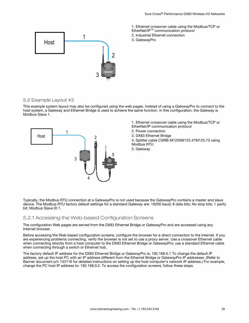
Host1
2
3
1. Ethernet crossover cable using the Modbus/TCP orEtherNet/IP™ communication protocol2. Industrial Ethernet connection3. GatewayPro
5.2 Example Layout #3This example system layout may also be configured using the web pages. Instead of using a GatewayPro to connect to thehost system, a Gateway and Ethernet Bridge is used to achieve the same function. In this configuration, the Gateway isModbus Slave 1.
Host1
2
3
4
5
1. Ethernet crossover cable using the Modbus/TCP orEtherNet/IP communication protocol2. Power connection3. DX83 Ethernet Bridge4. Splitter cable CSRB-M1250M125.47M125.73 usingModbus RTU5. Gateway
Typically, the Modbus RTU connection at a GatewayPro is not used because the GatewayPro contains a master and slavedevice. The Modbus RTU factory default settings for a standard Gateway are: 19200 baud; 8 data bits; No stop bits; 1 paritybit; Modbus Slave ID 1.
5.2.1 Accessing the Web-based Configuration ScreensThe configuration Web pages are served from the DX83 Ethernet Bridge or GatewayPro and are accessed using anyInternet browser.
Before accessing the Web-based configuration screens, configure the browser for a direct connection to the Internet. If youare experiencing problems connecting, verify the browser is not set to use a proxy server. Use a crossover Ethernet cablewhen connecting directly from a host computer to the DX83 Ethernet Bridge or GatewayPro; use a standard Ethernet cablewhen connecting through a switch or Ethernet hub.
The factory default IP address for the DX83 Ethernet Bridge or GatewayPro is: 192.168.0.1 To change the default IPaddress, set up the host PC with an IP address different from the Ethernet Bridge or GatewayPro IP addresses. (Refer toBanner document p/n 133116 for detailed instructions on setting up the host computer’s network IP address.) For example,change the PC host IP address to: 192.168.0.2. To access the configuration screens, follow these steps.
Sure Cross® Performance DX80 Wireless I/O Networks
www.bannerengineering.com - Tel: +1.763.544.3164 39
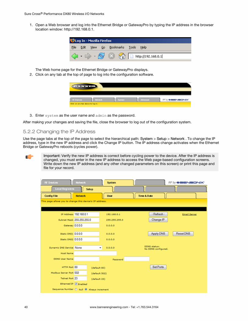
1. Open a Web browser and log into the Ethernet Bridge or GatewayPro by typing the IP address in the browserlocation window: http://192.168.0.1.
The Web home page for the Ethernet Bridge or GatewayPro displays.
2. Click on any tab at the top of page to log into the configuration software.
3. Enter system as the user name and admin as the password.
After making your changes and saving the file, close the browser to log out of the configuration system.
5.2.2 Changing the IP AddressUse the page tabs at the top of the page to select the hierarchical path: System > Setup > Network . To change the IPaddress, type in the new IP address and click the Change IP button. The IP address change activates when the EthernetBridge or GatewayPro reboots (cycles power).
Important: Verify the new IP address is correct before cycling power to the device. After the IP address ischanged, you must enter in the new IP address to access the Web page-based configuration screens.Write down the new IP address (and any other changed parameters on this screen) or print this page andfile for your record.
Sure Cross® Performance DX80 Wireless I/O Networks
40 www.bannerengineering.com - Tel: +1.763.544.3164
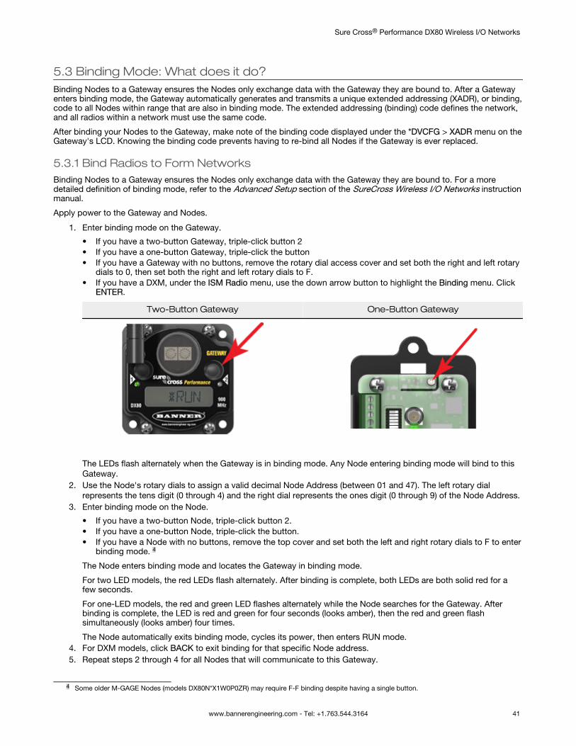
5.3 Binding Mode: What does it do?Binding Nodes to a Gateway ensures the Nodes only exchange data with the Gateway they are bound to. After a Gatewayenters binding mode, the Gateway automatically generates and transmits a unique extended addressing (XADR), or binding,code to all Nodes within range that are also in binding mode. The extended addressing (binding) code defines the network,and all radios within a network must use the same code.
After binding your Nodes to the Gateway, make note of the binding code displayed under the *DVCFG > XADR menu on theGateway's LCD. Knowing the binding code prevents having to re-bind all Nodes if the Gateway is ever replaced.
5.3.1 Bind Radios to Form NetworksBinding Nodes to a Gateway ensures the Nodes only exchange data with the Gateway they are bound to. For a moredetailed definition of binding mode, refer to the Advanced Setup section of the SureCross Wireless I/O Networks instructionmanual.
Apply power to the Gateway and Nodes.
1. Enter binding mode on the Gateway.
• If you have a two-button Gateway, triple-click button 2• If you have a one-button Gateway, triple-click the button• If you have a Gateway with no buttons, remove the rotary dial access cover and set both the right and left rotary
dials to 0, then set both the right and left rotary dials to F.• If you have a DXM, under the ISM Radio menu, use the down arrow button to highlight the Binding menu. Click
ENTER.
Two-Button Gateway One-Button Gateway
The LEDs flash alternately when the Gateway is in binding mode. Any Node entering binding mode will bind to thisGateway.
2. Use the Node's rotary dials to assign a valid decimal Node Address (between 01 and 47). The left rotary dialrepresents the tens digit (0 through 4) and the right dial represents the ones digit (0 through 9) of the Node Address.
3. Enter binding mode on the Node.
• If you have a two-button Node, triple-click button 2.• If you have a one-button Node, triple-click the button.• If you have a Node with no buttons, remove the top cover and set both the left and right rotary dials to F to enter
binding mode. 4
The Node enters binding mode and locates the Gateway in binding mode.
For two LED models, the red LEDs flash alternately. After binding is complete, both LEDs are both solid red for afew seconds.
For one-LED models, the red and green LED flashes alternately while the Node searches for the Gateway. Afterbinding is complete, the LED is red and green for four seconds (looks amber), then the red and green flashsimultaneously (looks amber) four times.
The Node automatically exits binding mode, cycles its power, then enters RUN mode.4. For DXM models, click BACK to exit binding for that specific Node address.5. Repeat steps 2 through 4 for all Nodes that will communicate to this Gateway.
4 Some older M-GAGE Nodes (models DX80N*X1W0P0ZR) may require F-F binding despite having a single button.
Sure Cross® Performance DX80 Wireless I/O Networks
www.bannerengineering.com - Tel: +1.763.544.3164 41
6. Exit binding mode on the Gateway.
• If you have a two-button Gateway, single-click either button.• If you have a one-button Gateway, single-click the button.• If you have a Gateway with no buttons, change the Gateway's rotary dials to a valid Network ID.• If you have a DXM, click BACK until you return to the main menu.
When installing special kits with pre-mapped I/O, indicated by device model numbers beginning in DX80K, return the rotarydials to their original positions after binding. If the rotary dials are not returned to their original positions, the I/O mappingwill not work.
5.3.2 Manually Assign a Binding Code to a GatewayManually assign the binding code (XADR) when replacing components of an existing wireless network.
To determine the existing binding code, access the DINFO (Device Information) menu of either the existing Gateway oranother Node in the network. Follow the submenu structure to the XADR display for that device.
1. Apply power to the Gateway.The Gateway’s LCD shows POWER, then RUN.
2. On the Gateway, single click button 1 to advance across the menus, stopping at the DVCFG menu.The Gateway’s LCD shows (DVCFG).
3. Single click button 2 to select DVCFG. Single click button 1 to select from the available menu options, stopping atXADR.
4. Single click button 2 to enter the XADR menu.AUTO is automatic binding mode and uses the Gateway’s serial number as the binding code.
5. Single click button 1 to select manual mode.6. Single click button 2 to enter manual mode.
MANUAL allows the user to manually enter an binding code.7. Single click button 2 to advance to the binding code entry step.
After entering manual mode, use the right rotary dial to select the digits of the binding code. The LCD shows SETXADR 000000.
8. Use the right rotary switch to begin setting the binding code. Digit selection begins with the left most digit. Afterselecting the first digit, single click button 1 to advance right to the next digit. All six digits must be filled, even if it iswith leading zeros. For example, to use 2245 as the code, enter 002245 into the device.To use the Gateway’s serial number, enter 000000 as the binding code.
9. Continue entering the code using a single click of button 1 to advance from left to right.After reaching the sixth digit, the curser returns to the first digit.
10. Single click button 2 when code entry is complete.The Gateway LCD displays the entered value for confirmation by showing CONFRM XADR, then repeating backyour value.
11. Single click button 2 to save the code and exit the XADR menu.
When entering the binding code, the digits auto fill with whatever position the rotary switch is currently in. For example, afterentering the 00 part of the binding code 002245, the third digit auto fills with a 0 until the rotary dial is rotated to 2.
After manually changing the binding code on a Gateway in an existing network, change the binding code for all Nodes inthat network by either manually setting the code on all Node(s) or by beginning the automatic binding sequence on theGateway and auto-binding all the Node(s).
5.3.3 Manually Assign a Binding Code to a NodeManually assign the binding code when replacing components of an existing wireless network.
To determine the existing binding code, access the DINFO (Device Information) menu of either the existing Gateway oranother Node in the network. Follow the submenu structure to the XADR display for that device.
1. Apply power to the Node.5
The LCD displays POWER, then RUN.2. On the Node, single click button 1 to advance across the menus, stopping at the DVCFG menu.3. Single click button 2 to select DVCFG. Single click button 1 to select from the available menu options, stopping at
XADR.4. Single click button 2 to enter the XADR menu.
AUTO is automatic binding mode and uses the Gateway’s serial number as the binding code.
5 For devices with batteries integrated into the housing, remove the battery for one minute to cycle power to the device.
Sure Cross® Performance DX80 Wireless I/O Networks
42 www.bannerengineering.com - Tel: +1.763.544.3164
5. Single click button 1, stopping at manual mode.MANUAL allows the user to manually enter a binding code.
6. Single click button 2 to enter manual mode.7. Single click button 2 to enter the binding code entry step.
The LCD shows SET XADR 000000.8. Use the right rotary switch to begin setting the binding code. Digit selection begins with the left most digit. After
selecting the first digit, single click button 1 to advance right to the next digit. All six digits must be filled, even if it iswith leading zeros. For example, to use 2245 as the code, enter 002245 into the device.
9. Continue entering the code using a single click of button 1 to advance from left to right.After reaching the sixth digit, the curser returns to the first digit.
10. Single click button 2 when code entry is complete. The Node LCD displays the entered value for confirmation.The LCD shows CONFRM XADR XXXXXX.
11. If the rotary dial hasn’t been returned to the previous Node address (device address or ID), the LCD displays theprior setting as a reminder. Return the rotary dial to its previous Node address.
12. The new Node address setting displays (NEW NADR XX).13. The Node confirms the new Node address by displaying CONFRM NADR XX.14. Double click button 2 to exit the XADR menu and to return to RUN mode.
When entering the binding code, the digits auto fill with whatever position the rotary switch is currently in. For example, afterentering the 00 part of the binding code 002245, the third digit auto fills with a 0 until the rotary dial is rotated to 2.
5.3.4 Automatic Binding Using the Menu NavigationThe easiest way to bind the Gateway to its Nodes is by triple clicking button 2 to enter automatic binding mode. If youwould prefer to begin automatic binding mode using the menu structure instead of the buttons, follow these steps.
Before making any changes to the DIP switches, disconnect the power to the devices. For devices with batteries integratedinto the housing, remove the battery.
1. On the Gateway: remove the top cover.2. Move DIP switch 1 to the ON position.
Extended Addressing Mode is activated using DIP switch 1.3. Apply power to the Gateway.
The Gateway's LCD displays POWER, then *RUN.4. On the Gateway, single click button 1 to advance across the menus, stopping at the DVCFG menu.
The Gateway's LCD displays (DVCFG).5. Single click button 2 to select DVCFG. Single click button 1 to select from the available menu options, stopping at
XADR.The Gateway's LCD displays (XADR).
6. Single click button 2 to enter XADR mode. When the display reads (AUTO), single click button 2 again to begin theautomatic binding mode.The LEDs flash alternately when the Gateway is in binding mode. Any Node entering binding mode will bind to thisGateway. The Gateway's LCD displays NETWRK BINDNG.
7. On the Node: remove the top cover.8. Move DIP switch 1 to the ON position.
Extended address mode is activated using DIP switch 1.9. Apply power to the Node.
The Node's LCD displays POWER, then *RUN.10. On the Node, single click button 1 to advance across the menus, stopping at the DVCFG menu.
The Node's LCD displays (DVCFG).11. Single click button 2 to enter the DVCFG menu.12. Single click button 1 to select from the available submenu options, stopping at XADR.
The Node's LCD displays (XADR).13. Single click button 2 to enter the XADR submenu.14. When the display reads (AUTO), single click button 2 to begin the automatic binding mode.
The Node enters binding mode. The Node's LCD displays NETWRK BINDNG. When the Node is bound, the LEDsare both solid red for a few seconds. The Node cycles its power, then enters RUN mode.
Sure Cross® Performance DX80 Wireless I/O Networks
www.bannerengineering.com - Tel: +1.763.544.3164 43
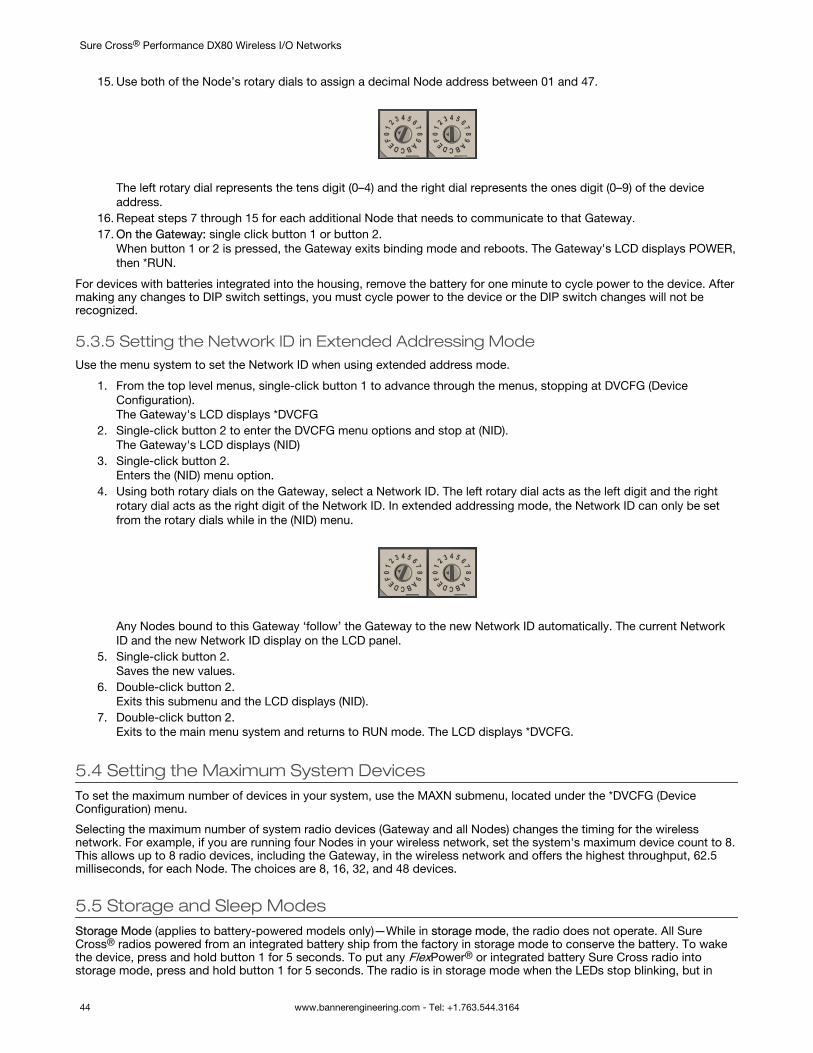
15. Use both of the Node’s rotary dials to assign a decimal Node address between 01 and 47.
The left rotary dial represents the tens digit (0–4) and the right dial represents the ones digit (0–9) of the deviceaddress.
16. Repeat steps 7 through 15 for each additional Node that needs to communicate to that Gateway.17. On the Gateway: single click button 1 or button 2.
When button 1 or 2 is pressed, the Gateway exits binding mode and reboots. The Gateway's LCD displays POWER,then *RUN.
For devices with batteries integrated into the housing, remove the battery for one minute to cycle power to the device. Aftermaking any changes to DIP switch settings, you must cycle power to the device or the DIP switch changes will not berecognized.
5.3.5 Setting the Network ID in Extended Addressing ModeUse the menu system to set the Network ID when using extended address mode.
1. From the top level menus, single-click button 1 to advance through the menus, stopping at DVCFG (DeviceConfiguration).The Gateway's LCD displays *DVCFG
2. Single-click button 2 to enter the DVCFG menu options and stop at (NID).The Gateway's LCD displays (NID)
3. Single-click button 2.Enters the (NID) menu option.
4. Using both rotary dials on the Gateway, select a Network ID. The left rotary dial acts as the left digit and the rightrotary dial acts as the right digit of the Network ID. In extended addressing mode, the Network ID can only be setfrom the rotary dials while in the (NID) menu.
Any Nodes bound to this Gateway ‘follow’ the Gateway to the new Network ID automatically. The current NetworkID and the new Network ID display on the LCD panel.
5. Single-click button 2.Saves the new values.
6. Double-click button 2.Exits this submenu and the LCD displays (NID).
7. Double-click button 2.Exits to the main menu system and returns to RUN mode. The LCD displays *DVCFG.
5.4 Setting the Maximum System DevicesTo set the maximum number of devices in your system, use the MAXN submenu, located under the *DVCFG (DeviceConfiguration) menu.
Selecting the maximum number of system radio devices (Gateway and all Nodes) changes the timing for the wirelessnetwork. For example, if you are running four Nodes in your wireless network, set the system's maximum device count to 8.This allows up to 8 radio devices, including the Gateway, in the wireless network and offers the highest throughput, 62.5milliseconds, for each Node. The choices are 8, 16, 32, and 48 devices.
5.5 Storage and Sleep ModesStorage Mode (applies to battery-powered models only)—While in storage mode, the radio does not operate. All SureCross® radios powered from an integrated battery ship from the factory in storage mode to conserve the battery. To wakethe device, press and hold button 1 for 5 seconds. To put any FlexPower® or integrated battery Sure Cross radio intostorage mode, press and hold button 1 for 5 seconds. The radio is in storage mode when the LEDs stop blinking, but in
Sure Cross® Performance DX80 Wireless I/O Networks
44 www.bannerengineering.com - Tel: +1.763.544.3164
some models, the LCD remains on for an additional minute after the radio enters storage mode. After a device has enteredstorage mode, you must wait 1 minute before waking it.
Sleep Mode (applies to both battery and 10–30 V dc powered models)—During normal operation, the Sure Cross radiodevices enter sleep mode after 15 minutes of operation. The radio continues to function, but the LCD goes blank. To wakethe device, press any button.
5.6 Modbus Holding RegistersThere are sixteen Modbus holding registers for each device. Calculate the holding register number for each device using theequation: Register number = I/O# + (Node# × 16).
The Gateway is always device 0 and the Gateway’s holding registers are registers 1 through 16. Registers for Node 1 are 17through 32. Although only seven Nodes are listed, the registers continue for as many Nodes as are in the network. Forexample, the register number for Node 10, I/O point 15, is 175.
Table 1: Modbus Holding Registers
I/O Point Gateway Node 1 Node 2 Node 3 Node 4 Node 5 Node 6 Node 7
1 1 17 33 49 65 81 97 113
2 2 18 34 50 66 82 98 114
3 3 19 35 51 67 83 99 115
4 4 20 36 52 68 84 100 116
5 5 21 37 53 69 85 101 117
6 6 22 38 54 70 86 102 118
7 7 23 39 55 71 87 103 119
8 8 24 40 56 72 88 104 120
9 9 25 41 57 73 89 105 121
10 10 26 42 58 74 90 106 122
11 11 27 43 59 75 91 107 123
12 12 28 44 60 76 92 108 124
13 13 29 45 61 77 93 109 125
14 14 30 46 62 78 94 110 126
15 15 31 47 63 79 95 111 127
16 16 32 48 64 80 96 112 128
5.7 Modbus Communication ParametersTo access the Modbus device, you may first need to configure system-level communication parameters on the Gateway.
The following procedures are necessary to change the Gateway's slave ID, baud rate, and parity. Setting up the Networkand Device IDs, powering up the devices, and conducting the Site Survey for a host-connected network is the same as forthe non-host DX80 or DX80 Performance wireless system. All device I/O for the network is accessed using the host/masterdevice.
Parameter Default Value Description
Slave ID 1 Defines the slave number (01–99) for the serial Modbus RTU protocol. When operating morethan one network with a Modbus Master device, change the Slave IDs.
Baud Rate 19200 Defines communication data rate (19.2, 38.4, or 9.6 kbps) between the Gateway and the Hostthrough the serial interface.
Parity None Defines serial parity (none, even, or odd) between Gateway and Host.
Sure Cross® Performance DX80 Wireless I/O Networks
www.bannerengineering.com - Tel: +1.763.544.3164 45
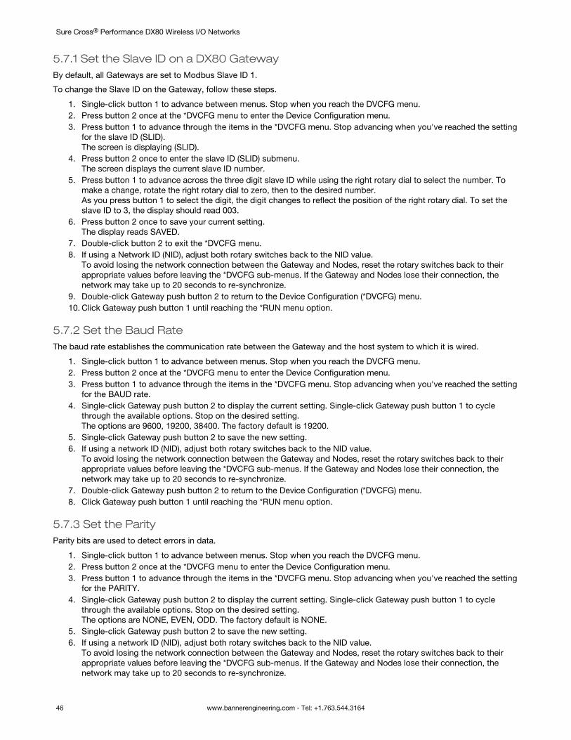
5.7.1 Set the Slave ID on a DX80 GatewayBy default, all Gateways are set to Modbus Slave ID 1.
To change the Slave ID on the Gateway, follow these steps.
1. Single-click button 1 to advance between menus. Stop when you reach the DVCFG menu.2. Press button 2 once at the *DVCFG menu to enter the Device Configuration menu.3. Press button 1 to advance through the items in the *DVCFG menu. Stop advancing when you've reached the setting
for the slave ID (SLID).The screen is displaying (SLID).
4. Press button 2 once to enter the slave ID (SLID) submenu.The screen displays the current slave ID number.
5. Press button 1 to advance across the three digit slave ID while using the right rotary dial to select the number. Tomake a change, rotate the right rotary dial to zero, then to the desired number.As you press button 1 to select the digit, the digit changes to reflect the position of the right rotary dial. To set theslave ID to 3, the display should read 003.
6. Press button 2 once to save your current setting.The display reads SAVED.
7. Double-click button 2 to exit the *DVCFG menu.8. If using a Network ID (NID), adjust both rotary switches back to the NID value.
To avoid losing the network connection between the Gateway and Nodes, reset the rotary switches back to theirappropriate values before leaving the *DVCFG sub-menus. If the Gateway and Nodes lose their connection, thenetwork may take up to 20 seconds to re-synchronize.
9. Double-click Gateway push button 2 to return to the Device Configuration (*DVCFG) menu.10. Click Gateway push button 1 until reaching the *RUN menu option.
5.7.2 Set the Baud RateThe baud rate establishes the communication rate between the Gateway and the host system to which it is wired.
1. Single-click button 1 to advance between menus. Stop when you reach the DVCFG menu.2. Press button 2 once at the *DVCFG menu to enter the Device Configuration menu.3. Press button 1 to advance through the items in the *DVCFG menu. Stop advancing when you've reached the setting
for the BAUD rate.4. Single-click Gateway push button 2 to display the current setting. Single-click Gateway push button 1 to cycle
through the available options. Stop on the desired setting.The options are 9600, 19200, 38400. The factory default is 19200.
5. Single-click Gateway push button 2 to save the new setting.6. If using a network ID (NID), adjust both rotary switches back to the NID value.
To avoid losing the network connection between the Gateway and Nodes, reset the rotary switches back to theirappropriate values before leaving the *DVCFG sub-menus. If the Gateway and Nodes lose their connection, thenetwork may take up to 20 seconds to re-synchronize.
7. Double-click Gateway push button 2 to return to the Device Configuration (*DVCFG) menu.8. Click Gateway push button 1 until reaching the *RUN menu option.
5.7.3 Set the ParityParity bits are used to detect errors in data.
1. Single-click button 1 to advance between menus. Stop when you reach the DVCFG menu.2. Press button 2 once at the *DVCFG menu to enter the Device Configuration menu.3. Press button 1 to advance through the items in the *DVCFG menu. Stop advancing when you've reached the setting
for the PARITY.4. Single-click Gateway push button 2 to display the current setting. Single-click Gateway push button 1 to cycle
through the available options. Stop on the desired setting.The options are NONE, EVEN, ODD. The factory default is NONE.
5. Single-click Gateway push button 2 to save the new setting.6. If using a network ID (NID), adjust both rotary switches back to the NID value.
To avoid losing the network connection between the Gateway and Nodes, reset the rotary switches back to theirappropriate values before leaving the *DVCFG sub-menus. If the Gateway and Nodes lose their connection, thenetwork may take up to 20 seconds to re-synchronize.
Sure Cross® Performance DX80 Wireless I/O Networks
46 www.bannerengineering.com - Tel: +1.763.544.3164
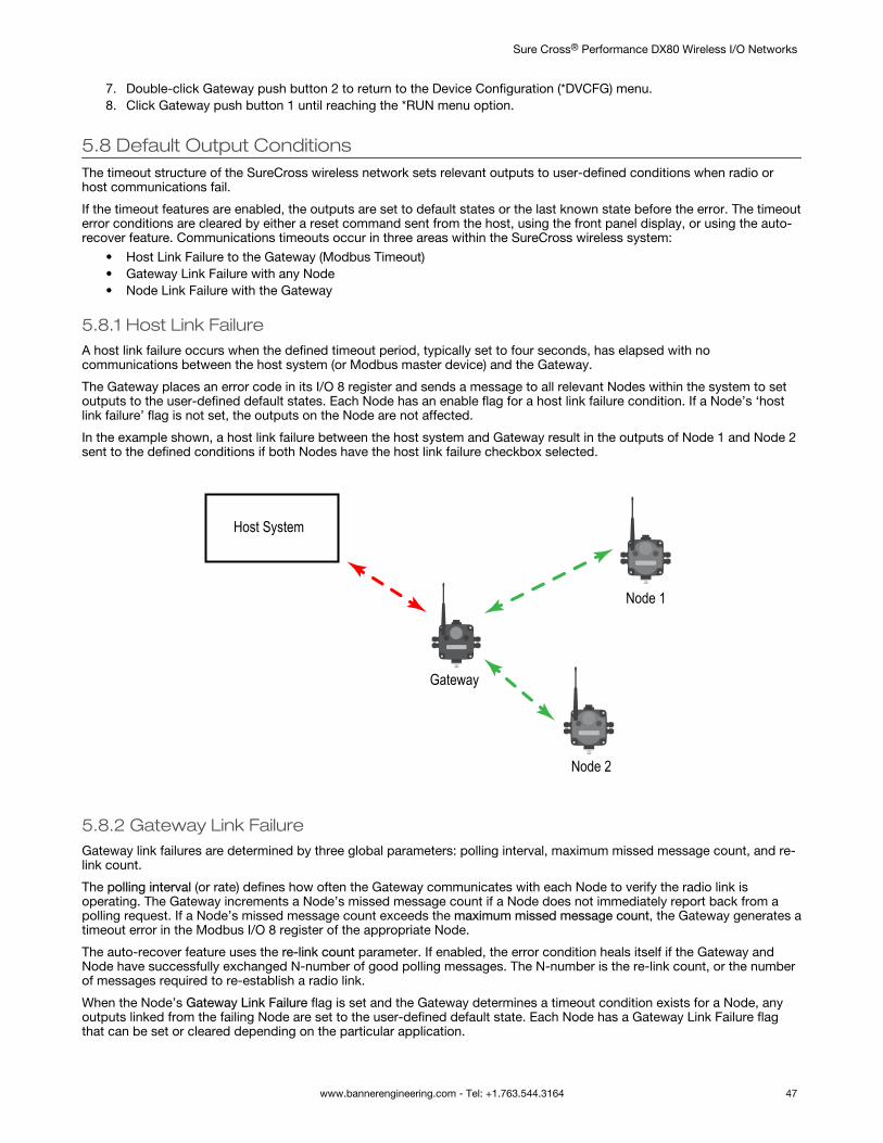
7. Double-click Gateway push button 2 to return to the Device Configuration (*DVCFG) menu.8. Click Gateway push button 1 until reaching the *RUN menu option.
5.8 Default Output ConditionsThe timeout structure of the SureCross wireless network sets relevant outputs to user-defined conditions when radio orhost communications fail.
If the timeout features are enabled, the outputs are set to default states or the last known state before the error. The timeouterror conditions are cleared by either a reset command sent from the host, using the front panel display, or using the auto-recover feature. Communications timeouts occur in three areas within the SureCross wireless system:
• Host Link Failure to the Gateway (Modbus Timeout)• Gateway Link Failure with any Node• Node Link Failure with the Gateway
5.8.1 Host Link FailureA host link failure occurs when the defined timeout period, typically set to four seconds, has elapsed with nocommunications between the host system (or Modbus master device) and the Gateway.
The Gateway places an error code in its I/O 8 register and sends a message to all relevant Nodes within the system to setoutputs to the user-defined default states. Each Node has an enable flag for a host link failure condition. If a Node’s ‘hostlink failure’ flag is not set, the outputs on the Node are not affected.
In the example shown, a host link failure between the host system and Gateway result in the outputs of Node 1 and Node 2sent to the defined conditions if both Nodes have the host link failure checkbox selected.
Host System
Gateway
Node 1
Node 2
5.8.2 Gateway Link FailureGateway link failures are determined by three global parameters: polling interval, maximum missed message count, and re-link count.
The polling interval (or rate) defines how often the Gateway communicates with each Node to verify the radio link isoperating. The Gateway increments a Node’s missed message count if a Node does not immediately report back from apolling request. If a Node’s missed message count exceeds the maximum missed message count, the Gateway generates atimeout error in the Modbus I/O 8 register of the appropriate Node.
The auto-recover feature uses the re-link count parameter. If enabled, the error condition heals itself if the Gateway andNode have successfully exchanged N-number of good polling messages. The N-number is the re-link count, or the numberof messages required to re-establish a radio link.
When the Node’s Gateway Link Failure flag is set and the Gateway determines a timeout condition exists for a Node, anyoutputs linked from the failing Node are set to the user-defined default state. Each Node has a Gateway Link Failure flagthat can be set or cleared depending on the particular application.
Sure Cross® Performance DX80 Wireless I/O Networks
www.bannerengineering.com - Tel: +1.763.544.3164 47
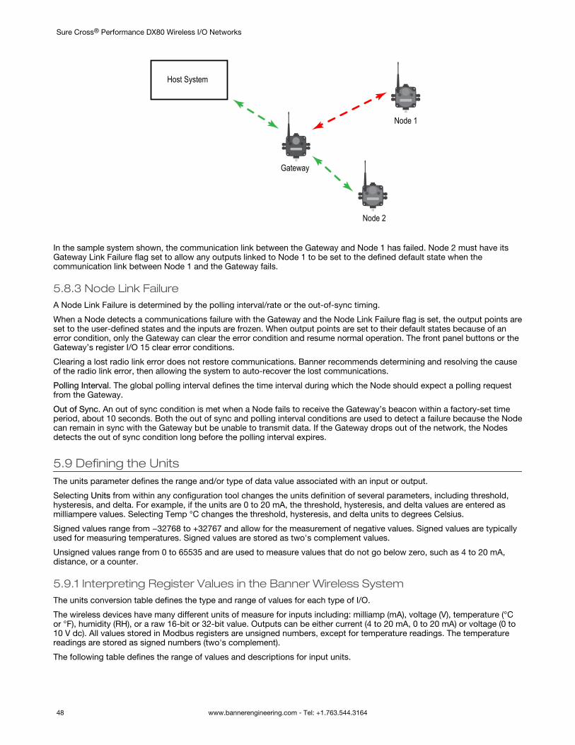
Host System
Gateway
Node 1
Node 2
In the sample system shown, the communication link between the Gateway and Node 1 has failed. Node 2 must have itsGateway Link Failure flag set to allow any outputs linked to Node 1 to be set to the defined default state when thecommunication link between Node 1 and the Gateway fails.
5.8.3 Node Link FailureA Node Link Failure is determined by the polling interval/rate or the out-of-sync timing.
When a Node detects a communications failure with the Gateway and the Node Link Failure flag is set, the output points areset to the user-defined states and the inputs are frozen. When output points are set to their default states because of anerror condition, only the Gateway can clear the error condition and resume normal operation. The front panel buttons or theGateway’s register I/O 15 clear error conditions.
Clearing a lost radio link error does not restore communications. Banner recommends determining and resolving the causeof the radio link error, then allowing the system to auto-recover the lost communications.
Polling Interval. The global polling interval defines the time interval during which the Node should expect a polling requestfrom the Gateway.
Out of Sync. An out of sync condition is met when a Node fails to receive the Gateway’s beacon within a factory-set timeperiod, about 10 seconds. Both the out of sync and polling interval conditions are used to detect a failure because the Nodecan remain in sync with the Gateway but be unable to transmit data. If the Gateway drops out of the network, the Nodesdetects the out of sync condition long before the polling interval expires.
5.9 Defining the UnitsThe units parameter defines the range and/or type of data value associated with an input or output.
Selecting Units from within any configuration tool changes the units definition of several parameters, including threshold,hysteresis, and delta. For example, if the units are 0 to 20 mA, the threshold, hysteresis, and delta values are entered asmilliampere values. Selecting Temp °C changes the threshold, hysteresis, and delta units to degrees Celsius.
Signed values range from −32768 to +32767 and allow for the measurement of negative values. Signed values are typicallyused for measuring temperatures. Signed values are stored as two's complement values.
Unsigned values range from 0 to 65535 and are used to measure values that do not go below zero, such as 4 to 20 mA,distance, or a counter.
5.9.1 Interpreting Register Values in the Banner Wireless SystemThe units conversion table defines the type and range of values for each type of I/O.
The wireless devices have many different units of measure for inputs including: milliamp (mA), voltage (V), temperature (°Cor °F), humidity (RH), or a raw 16-bit or 32-bit value. Outputs can be either current (4 to 20 mA, 0 to 20 mA) or voltage (0 to10 V dc). All values stored in Modbus registers are unsigned numbers, except for temperature readings. The temperaturereadings are stored as signed numbers (two's complement).
The following table defines the range of values and descriptions for input units.
Sure Cross® Performance DX80 Wireless I/O Networks
48 www.bannerengineering.com - Tel: +1.763.544.3164
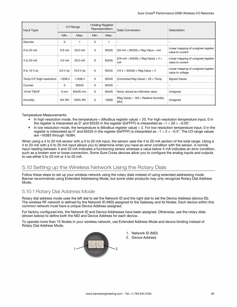
Input TypeI/O Range
Holding RegisterRepresentation Data Conversion Description
Min. Max. Min. Max.
Discrete 0 1 0 1 - -
0 to 20 mA 0.0 mA 20.0 mA 0 65535 (20 mA ÷ 65535) × Reg Value = mALinear mapping of unsigned registervalue to current
4 to 20 mA 4.0 mA 20.0 mA 0 65535((16 mA ÷ 65535) × Reg Value) + 4 =mA
Linear mapping of unsigned registervalue to current
0 to 10 V dc 0.0 V dc 10.0 V dc 0 65535 (10 V ÷ 65535) × Reg Value = VLinear mapping of unsigned registervalue to voltage
Temp C/F (high resolution) –1638.3 +1638.4 0 65535 (Converted Reg Value) ÷ 20 = Temp Signed Values
Counter 0 65535 0 65535 - -
16-bit T30UF 0 mm 65535 mm 0 65535 None; stored as millimeter value Unsigned
Humidity 0% RH 100% RH 0 10000(Reg Value) ÷ 100 = Relative Humidity(RH)
Unsigned
Temperature Measurements:• In high resolution mode, the temperature = (Modbus register value) ÷ 20. For high resolution temperature input, 0 in
the register is interpreted as 0° and 65535 in the register (0xFFFF) is interpreted as −1 ÷ 20 = −0.05°.• In low resolution mode, the temperature is (Modbus register value) ÷ 2. For low resolution temperature input, 0 in the
register is interpreted as 0° and 65535 in the register (0xFFFF) is interpreted as −1 ÷ 2 = −0.5°. The I/O range valuesare –16383 through 16384.
When using a 4 to 20 mA sensor with a 0 to 20 mA input, the sensor uses the 4 to 20 mA section of the total range. Using a4 to 20 mA with a 0 to 20 mA input allows you to determine when you have an error condition with the sensor. A normalinput reading between 4 and 20 mA indicates a functioning sensor whereas a value below 4 mA indicates an error condition,such as a broken wire or loose connection. Some Sure Cross devices allow you to configure the analog inputs and outputsto use either 0 to 20 mA or 4 to 20 mA.
5.10 Setting up the Wireless Network Using the Rotary DialsFollow these steps to set up your wireless network using the rotary dials instead of using extended addressing mode.Banner recommends using Extended Addressing Mode, but some older products may only recognize Rotary Dial AddressMode.
5.10.1 Rotary Dial Address ModeRotary dial address mode uses the left dial to set the Network ID and the right dial to set the Device Address (device ID).The wireless RF network is defined by the Network ID (NID) assigned to the Gateway and its Nodes. Each device within thiscommon network must have a unique Device Address assigned.
For factory configured kits, the Network ID and Device Addresses have been assigned. Otherwise, use the rotary dials(shown below) to define both the NID and Device Address for each device.
To operate more than 15 Nodes in your wireless network, use Extended Address Mode and device binding instead ofRotary Dial Address Mode.
1. Network ID (NID)2. Device Address
Sure Cross® Performance DX80 Wireless I/O Networks
www.bannerengineering.com - Tel: +1.763.544.3164 49
5.10.2 Setting the Network ID Using the Rotary DialsThe wireless network is defined by the Network ID (NID) assigned to the Gateway and its Nodes.
Each device within this common network must have a unique Device Address assigned. When using Rotary Dial AddressMode, set the Network ID on the Gateway and all its Nodes using the left rotary dial.
1. Remove rotary dial access covers. Turn counterclockwise to remove and clockwise to tighten.2. On the Gateway, set the left rotary dial to 1. The factory default NID setting on all devices is 1.3. On all Nodes within the same network, set the left rotary dial to 1. Assign the same NID to all devices within a single
network (hexadecimal 0-F).
When more than one network is operating in the same space, assign a unique Network ID to each network.
5.10.3 Setting the Device Address Using the Rotary DialsThe Device ID establishes a unique identifier for each device within a wireless network.
1. On the Gateway, set the right rotary dial to 0.A device address of 0 on the Gateway displays settings for the Gateway itself. To view settings for another deviceon the network, adjust the right rotary dial on the Gateway to the desired device address.
2. On the first Node (device address = 1), set the right rotary dial to 1. Do not change the Device ID for pre-configuredkits as this would affect the factory mapping of the I/O.
3. On the second Node (device address = 2), set the right rotary dial to 2.4. Continue setting the device address for each additional Node using a unique number (...3,4,5).
After setting both the Network ID and Device Address for all devices, re-install the rotary dial access covers, referring to theInstallation section for IP67 instructions. A successful radio link is identified by a blinking green LED 1 on each Node.
5.10.4 Setting Up Channel Search ModeA Gateway runs Channel Search Mode on power up or when the Gateway’s Network ID is changed.
Before beginning, apply power to the Gateway.
After Channel Search Mode begins, the Gateway determines if its assigned Network ID is available for use or is already inuse by another radio network. For example, if a Gateway powers up set to Network ID 2, Channel Search Mode beginsrunning as shown below.
1. Apply power to the Gateway and set the rotary dial to a Network ID number (shown here as Network ID 2).Channel Search Mode begins running, and LED 1 is solid red and LED 2 is flashing amber. The LCD displays STARTCHANNL SEARCH MODE. The test takes one minute to complete and counts down from 60 seconds. The LCDshows SEARCH NID 2 1M 0S. If the Network ID is not already in use, the LCD displays NID OK and enters RUNmode.
2. If the Network ID is already in use by another DX80 Gateway device, an IN USE message displays. Use the leftrotary dial to select another ID.
3. After selecting a new Network ID, click button two once to restart Channel Search Mode.The screen cycles between displaying the current Network ID setting and a new NID setting until either the left rotarydial is changed to another Network ID or the test is aborted. (LED 1 is solid red and LED 2 flashes red.) Once a newNetwork ID is selected, Channel Search Mode begins again.
4. After entering RUN mode, the LCD display shows the current I/O status of the Gateway.The Gateway and GatewayPro start in *RUN mode. The LCD shows the current Network ID (NID), identifies thedevice, then beings cycling through the I/O points (GatewayPro has no I/O points).
To cancel Channel Search Mode, double-click button two. The word ABORT displays on the LCD and both LEDs are solidred. The Gateway enters RUN mode, operating on the Network ID chosen.
To ignore the Channel Search Mode results and use a Network ID that Channel Search Mode determined was in use,double-click button two. The word IGNORE displays on the LCD and both LEDs are solid red. The Gateway enters RUNmode, operating on the Network ID chosen despite being in use by another device.
Channel Search Mode Flowchart
The example shown below is testing Network ID 2.
Sure Cross® Performance DX80 Wireless I/O Networks
50 www.bannerengineering.com - Tel: +1.763.544.3164
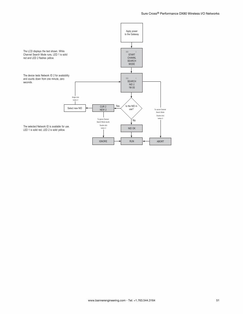
The LCD displays the text shown. While Channel Search Mode runs, LED 1 is solid red and LED 2 flashes yellow.
The device tests Network ID 2 for availability and counts down from one minute, zero seconds.
The selected Network ID is available for use. LED 1 is solid red, LED 2 is solid yellow.
START
CHANNLSEARCH
MODE
SEARCH
NID 21M 0S
Is the NID in use?
No
Yes
NID OK
RUN
CUR 2NEW 2Select new NID
Single click button 2
IGNORE
Double click button 2
ABORT
Double click button 2
Apply powerto the Gateway
To cancel Channel Search Mode
To ignore Channel Search Mode results
Sure Cross® Performance DX80 Wireless I/O Networks
www.bannerengineering.com - Tel: +1.763.544.3164 51
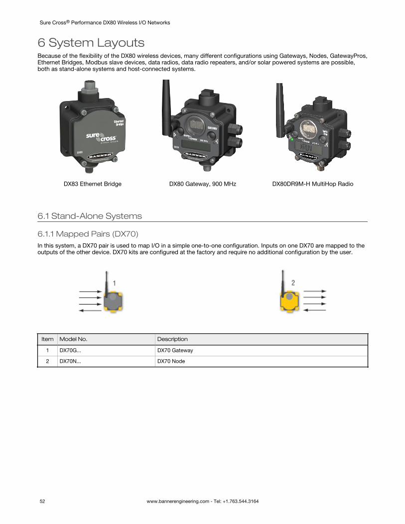
6 System LayoutsBecause of the flexibility of the DX80 wireless devices, many different configurations using Gateways, Nodes, GatewayPros,Ethernet Bridges, Modbus slave devices, data radios, data radio repeaters, and/or solar powered systems are possible,both as stand-alone systems and host-connected systems.
DX83 Ethernet Bridge DX80 Gateway, 900 MHz DX80DR9M-H MultiHop Radio
6.1 Stand-Alone Systems
6.1.1 Mapped Pairs (DX70)In this system, a DX70 pair is used to map I/O in a simple one-to-one configuration. Inputs on one DX70 are mapped to theoutputs of the other device. DX70 kits are configured at the factory and require no additional configuration by the user.
Item Model No. Description
1 DX70G... DX70 Gateway
2 DX70N... DX70 Node
Sure Cross® Performance DX80 Wireless I/O Networks
52 www.bannerengineering.com - Tel: +1.763.544.3164
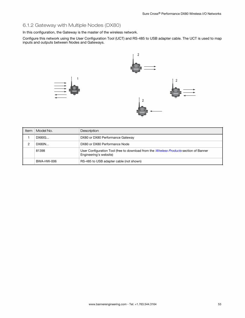
6.1.2 Gateway with Multiple Nodes (DX80)In this configuration, the Gateway is the master of the wireless network.
Configure this network using the User Configuration Tool (UCT) and RS-485 to USB adapter cable. The UCT is used to mapinputs and outputs between Nodes and Gateways.
1
2
2
2
Item Model No. Description
1 DX80G... DX80 or DX80 Performance Gateway
2 DX80N... DX80 or DX80 Performance Node
81398 User Configuration Tool (free to download from the Wireless Products section of BannerEngineering's website)
BWA-HW-006 RS-485 to USB adapter cable (not shown)
Sure Cross® Performance DX80 Wireless I/O Networks
www.bannerengineering.com - Tel: +1.763.544.3164 53
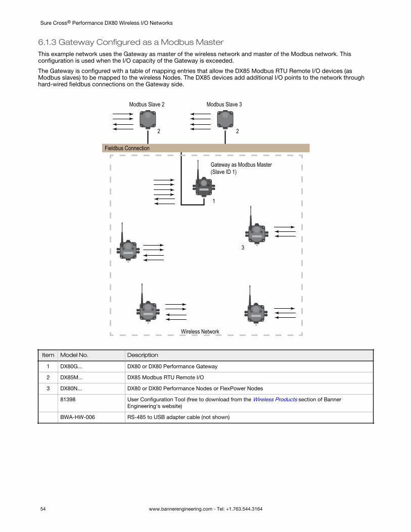
6.1.3 Gateway Configured as a Modbus MasterThis example network uses the Gateway as master of the wireless network and master of the Modbus network. Thisconfiguration is used when the I/O capacity of the Gateway is exceeded.
The Gateway is configured with a table of mapping entries that allow the DX85 Modbus RTU Remote I/O devices (asModbus slaves) to be mapped to the wireless Nodes. The DX85 devices add additional I/O points to the network throughhard-wired fieldbus connections on the Gateway side.
Fieldbus Connection
Modbus Slave 2 Modbus Slave 3
2 2
1
Gateway as Modbus Master(Slave ID 1)
3
Wireless Network
Item Model No. Description
1 DX80G... DX80 or DX80 Performance Gateway
2 DX85M... DX85 Modbus RTU Remote I/O
3 DX80N... DX80 or DX80 Performance Nodes or FlexPower Nodes
81398 User Configuration Tool (free to download from the Wireless Products section of BannerEngineering's website)
BWA-HW-006 RS-485 to USB adapter cable (not shown)
Sure Cross® Performance DX80 Wireless I/O Networks
54 www.bannerengineering.com - Tel: +1.763.544.3164
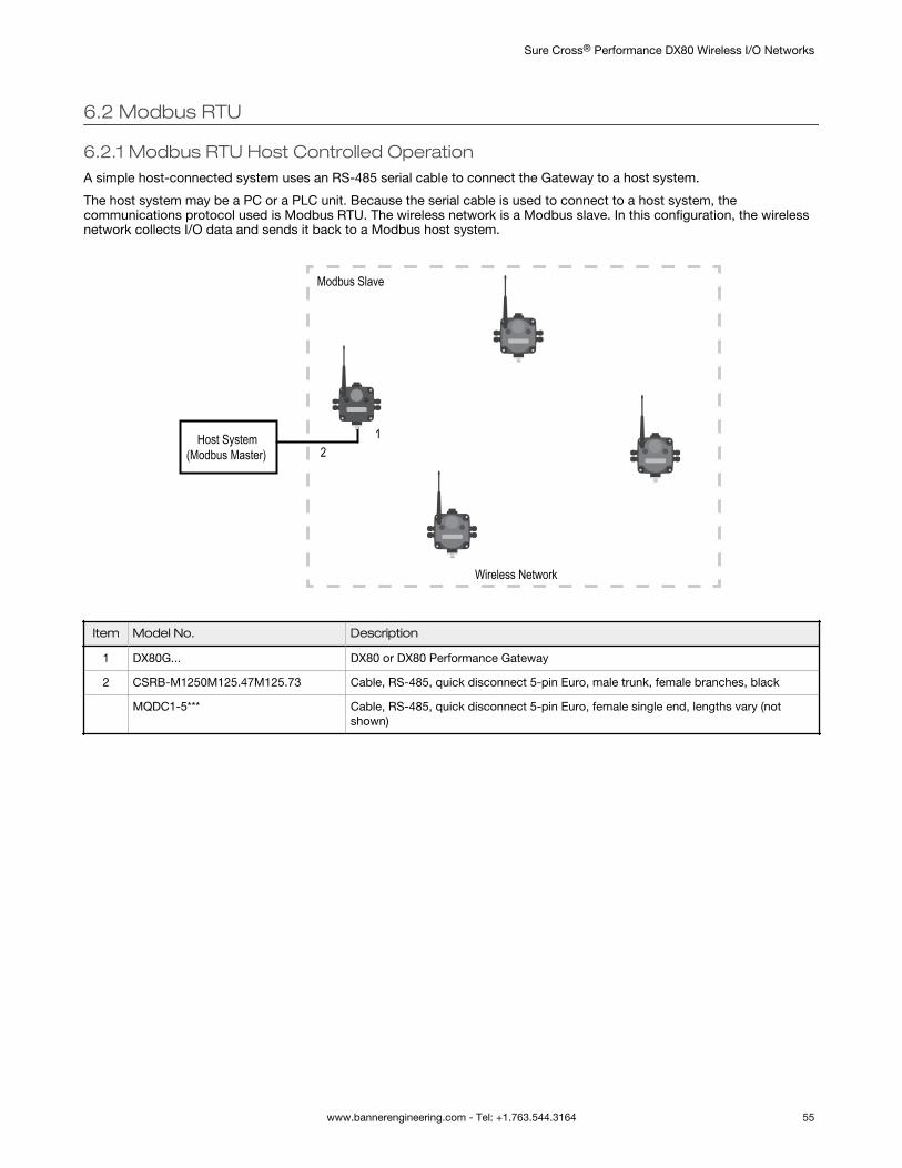
6.2 Modbus RTU
6.2.1 Modbus RTU Host Controlled OperationA simple host-connected system uses an RS-485 serial cable to connect the Gateway to a host system.
The host system may be a PC or a PLC unit. Because the serial cable is used to connect to a host system, thecommunications protocol used is Modbus RTU. The wireless network is a Modbus slave. In this configuration, the wirelessnetwork collects I/O data and sends it back to a Modbus host system.
1
Wireless Network
Host System(Modbus Master) 2
Modbus Slave
Item Model No. Description
1 DX80G... DX80 or DX80 Performance Gateway
2 CSRB-M1250M125.47M125.73 Cable, RS-485, quick disconnect 5-pin Euro, male trunk, female branches, black
MQDC1-5*** Cable, RS-485, quick disconnect 5-pin Euro, female single end, lengths vary (notshown)
Sure Cross® Performance DX80 Wireless I/O Networks
www.bannerengineering.com - Tel: +1.763.544.3164 55
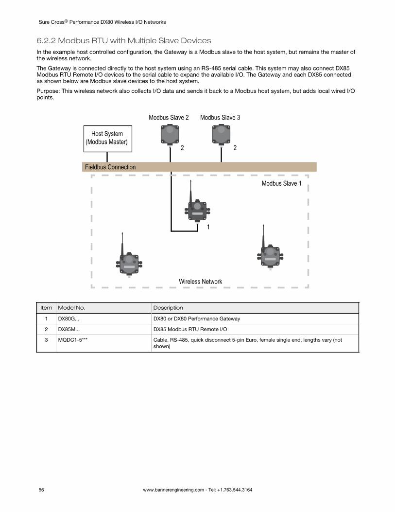
6.2.2 Modbus RTU with Multiple Slave DevicesIn the example host controlled configuration, the Gateway is a Modbus slave to the host system, but remains the master ofthe wireless network.
The Gateway is connected directly to the host system using an RS-485 serial cable. This system may also connect DX85Modbus RTU Remote I/O devices to the serial cable to expand the available I/O. The Gateway and each DX85 connectedas shown below are Modbus slave devices to the host system.
Purpose: This wireless network also collects I/O data and sends it back to a Modbus host system, but adds local wired I/Opoints.
Fieldbus Connection
Modbus Slave 2 Modbus Slave 3
2 2
1
Modbus Slave 1
Wireless Network
Host System(Modbus Master)
Item Model No. Description
1 DX80G... DX80 or DX80 Performance Gateway
2 DX85M... DX85 Modbus RTU Remote I/O
3 MQDC1-5*** Cable, RS-485, quick disconnect 5-pin Euro, female single end, lengths vary (notshown)
Sure Cross® Performance DX80 Wireless I/O Networks
56 www.bannerengineering.com - Tel: +1.763.544.3164
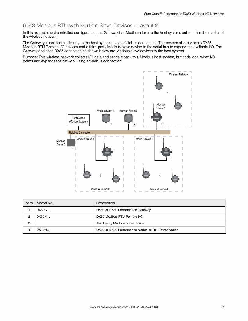
6.2.3 Modbus RTU with Multiple Slave Devices - Layout 2In this example host controlled configuration, the Gateway is a Modbus slave to the host system, but remains the master ofthe wireless network.
The Gateway is connected directly to the host system using a fieldbus connection. This system also connects DX85Modbus RTU Remote I/O devices and a third-party Modbus slave device to the serial bus to expand the available I/O. TheGateway and each DX85 connected as shown below are Modbus slave devices to the host system.
Purpose: This wireless network collects I/O data and sends it back to a Modbus host system, but adds local wired I/Opoints and expands the network using a fieldbus connection.
Fieldbus Connection
Modbus Slave 4 Modbus Slave 5
2 2
1
Modbus Slave 1
Wireless Network
Host System(Modbus Master)
4
1
Modbus Slave 3
Wireless Network
4
ModbusSlave 6
1
ModbusSlave 2
Wireless Network
4
3
Item Model No. Description
1 DX80G... DX80 or DX80 Performance Gateway
2 DX85M... DX85 Modbus RTU Remote I/O
3 Third party Modbus slave device
4 DX80N... DX80 or DX80 Performance Nodes or FlexPower Nodes
Sure Cross® Performance DX80 Wireless I/O Networks
www.bannerengineering.com - Tel: +1.763.544.3164 57
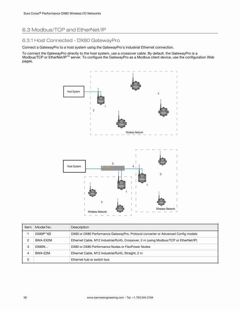
6.3 Modbus/TCP and EtherNet/IP
6.3.1 Host Connected - DX80 GatewayProConnect a GatewayPro to a host system using the GatewayPro's industrial Ethernet connection.
To connect the GatewayPro directly to the host system, use a crossover cable. By default, the GatewayPro is aModbus/TCP or EtherNet/IP™ server. To configure the GatewayPro as a Modbus client device, use the configuration Webpages.
1
Wireless Network
Host System
2
3
1
Wireless Network
3
1
Host System5
4
3
Wireless Network
Item Model No. Description
1 DX80P**6S DX80 or DX80 Performance GatewayPro, Protocol converter or Advanced Config models
2 BWA-EX2M Ethernet Cable, M12 Industrial/RJ45, Crossover, 2 m (using Modbus/TCP or EtherNet/IP)
3 DX80N... DX80 or DX80 Performance Nodes or FlexPower Nodes
4 BWA-E2M Ethernet Cable, M12 Industrial/RJ45, Straight, 2 m
5 Ethernet hub or switch box
Sure Cross® Performance DX80 Wireless I/O Networks
58 www.bannerengineering.com - Tel: +1.763.544.3164
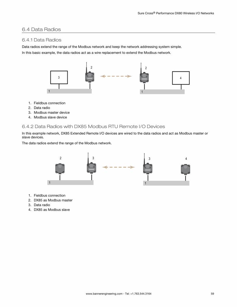
6.4 Data Radios
6.4.1 Data RadiosData radios extend the range of the Modbus network and keep the network addressing system simple.
In this basic example, the data radios act as a wire replacement to extend the Modbus network.
1
3
2
1
4
2
1. Fieldbus connection2. Data radio3. Modbus master device4. Modbus slave device
6.4.2 Data Radios with DX85 Modbus RTU Remote I/O DevicesIn this example network, DX85 Extended Remote I/O devices are wired to the data radios and act as Modbus master orslave devices.
The data radios extend the range of the Modbus network.
1
3
1
32 4
1. Fieldbus connection2. DX85 as Modbus master3. Data radio4. DX85 as Modbus slave
Sure Cross® Performance DX80 Wireless I/O Networks
www.bannerengineering.com - Tel: +1.763.544.3164 59
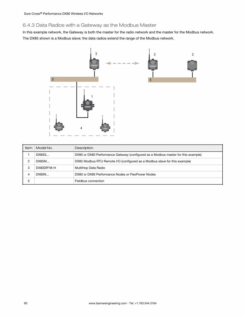
6.4.3 Data Radios with a Gateway as the Modbus MasterIn this example network, the Gateway is both the master for the radio network and the master for the Modbus network.
The DX85 shown is a Modbus slave; the data radios extend the range of the Modbus network.
5
3
5
3 2
1
4
Item Model No. Description
1 DX80G... DX80 or DX80 Performance Gateway (configured as a Modbus master for this example)
2 DX85M... DX85 Modbus RTU Remote I/O (configured as a Modbus slave for this example)
3 DX80DR*M-H MultiHop Data Radio
4 DX80N... DX80 or DX80 Performance Nodes or FlexPower Nodes
5 Fieldbus connection
Sure Cross® Performance DX80 Wireless I/O Networks
60 www.bannerengineering.com - Tel: +1.763.544.3164
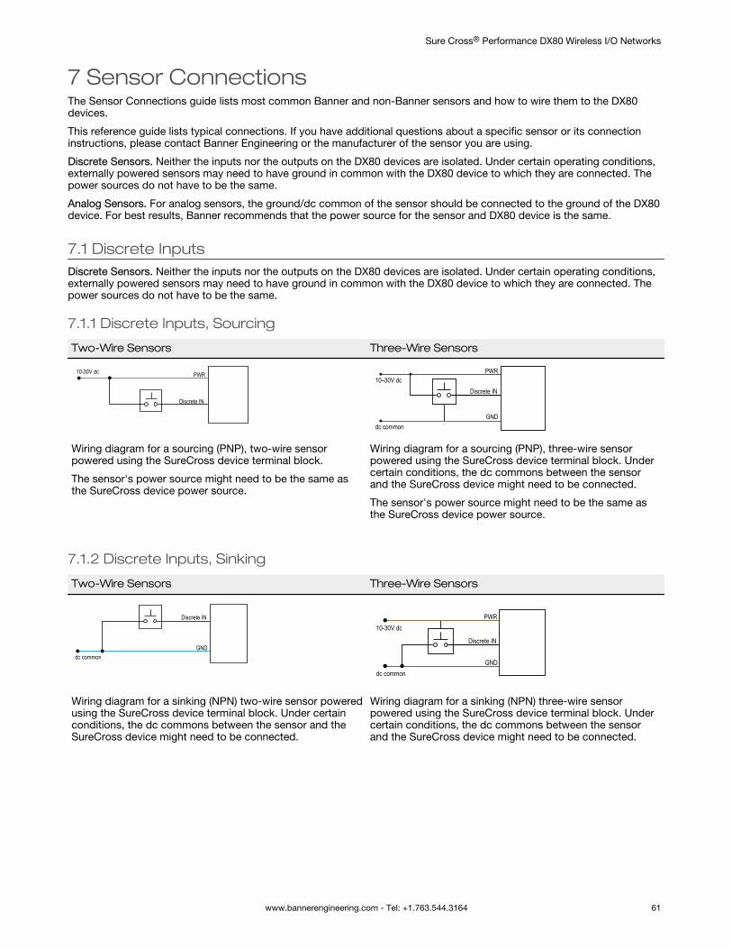
7 Sensor ConnectionsThe Sensor Connections guide lists most common Banner and non-Banner sensors and how to wire them to the DX80devices.
This reference guide lists typical connections. If you have additional questions about a specific sensor or its connectioninstructions, please contact Banner Engineering or the manufacturer of the sensor you are using.
Discrete Sensors. Neither the inputs nor the outputs on the DX80 devices are isolated. Under certain operating conditions,externally powered sensors may need to have ground in common with the DX80 device to which they are connected. Thepower sources do not have to be the same.
Analog Sensors. For analog sensors, the ground/dc common of the sensor should be connected to the ground of the DX80device. For best results, Banner recommends that the power source for the sensor and DX80 device is the same.
7.1 Discrete InputsDiscrete Sensors. Neither the inputs nor the outputs on the DX80 devices are isolated. Under certain operating conditions,externally powered sensors may need to have ground in common with the DX80 device to which they are connected. Thepower sources do not have to be the same.
7.1.1 Discrete Inputs, Sourcing
Two-Wire Sensors Three-Wire Sensors
Discrete IN
PWR10-30V dc
Discrete IN
GNDdc common
PWR10–30V dc
Wiring diagram for a sourcing (PNP), two-wire sensorpowered using the SureCross device terminal block.
The sensor's power source might need to be the same asthe SureCross device power source.
Wiring diagram for a sourcing (PNP), three-wire sensorpowered using the SureCross device terminal block. Undercertain conditions, the dc commons between the sensorand the SureCross device might need to be connected.
The sensor's power source might need to be the same asthe SureCross device power source.
7.1.2 Discrete Inputs, Sinking
Two-Wire Sensors Three-Wire Sensors
Discrete IN
GNDdc common
Discrete IN
GND
PWR10-30V dc
dc common
Wiring diagram for a sinking (NPN) two-wire sensor poweredusing the SureCross device terminal block. Under certainconditions, the dc commons between the sensor and theSureCross device might need to be connected.
Wiring diagram for a sinking (NPN) three-wire sensorpowered using the SureCross device terminal block. Undercertain conditions, the dc commons between the sensorand the SureCross device might need to be connected.
Sure Cross® Performance DX80 Wireless I/O Networks
www.bannerengineering.com - Tel: +1.763.544.3164 61
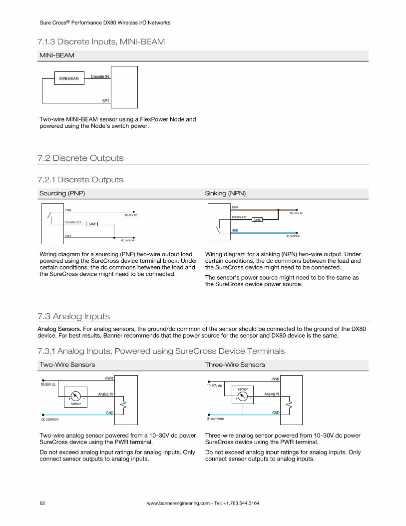
7.1.3 Discrete Inputs, MINI-BEAM
MINI-BEAM
Discrete IN
SP1
MINI-BEAM
Two-wire MINI-BEAM sensor using a FlexPower Node andpowered using the Node’s switch power.
7.2 Discrete Outputs
7.2.1 Discrete Outputs
Sourcing (PNP) Sinking (NPN)
Discrete OUT
GND
PWR10-30V dc
Load
dc common
LoadDiscrete OUT
GND
PWR
10–30 V dc
dc common
Wiring diagram for a sourcing (PNP) two-wire output loadpowered using the SureCross device terminal block. Undercertain conditions, the dc commons between the load andthe SureCross device might need to be connected.
Wiring diagram for a sinking (NPN) two-wire output. Undercertain conditions, the dc commons between the load andthe SureCross device might need to be connected.
The sensor's power source might need to be the same asthe SureCross device power source.
7.3 Analog InputsAnalog Sensors. For analog sensors, the ground/dc common of the sensor should be connected to the ground of the DX80device. For best results, Banner recommends that the power source for the sensor and DX80 device is the same.
7.3.1 Analog Inputs, Powered using SureCross Device Terminals
Two-Wire Sensors Three-Wire Sensors
Analog IN
PWR10-30V dc
GND
−+sensor
dc common
Analog IN
PWR10-30V dc
GND
−+
sensor
dc common
Two-wire analog sensor powered from a 10–30V dc powerSureCross device using the PWR terminal.
Do not exceed analog input ratings for analog inputs. Onlyconnect sensor outputs to analog inputs.
Three-wire analog sensor powered from 10–30V dc powerSureCross device using the PWR terminal.
Do not exceed analog input ratings for analog inputs. Onlyconnect sensor outputs to analog inputs.
Sure Cross® Performance DX80 Wireless I/O Networks
62 www.bannerengineering.com - Tel: +1.763.544.3164
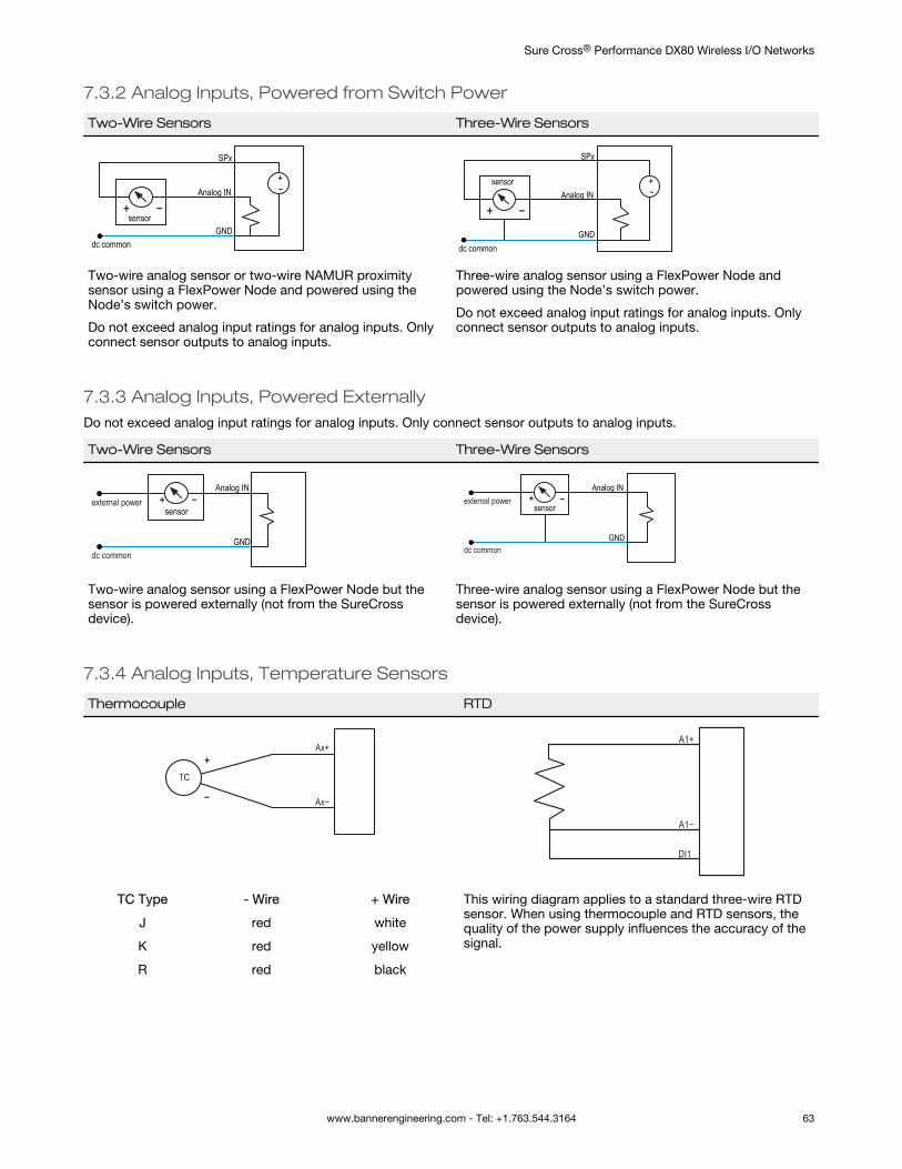
7.3.2 Analog Inputs, Powered from Switch Power
Two-Wire Sensors Three-Wire Sensors
+−Analog IN
SPx
GND
−+sensor
dc common
+−Analog IN
SPx
GND
−+
sensor
dc common
Two-wire analog sensor or two-wire NAMUR proximitysensor using a FlexPower Node and powered using theNode’s switch power.
Do not exceed analog input ratings for analog inputs. Onlyconnect sensor outputs to analog inputs.
Three-wire analog sensor using a FlexPower Node andpowered using the Node’s switch power.
Do not exceed analog input ratings for analog inputs. Onlyconnect sensor outputs to analog inputs.
7.3.3 Analog Inputs, Powered ExternallyDo not exceed analog input ratings for analog inputs. Only connect sensor outputs to analog inputs.
Two-Wire Sensors Three-Wire Sensors
Analog IN
GNDdc common
external power −+sensor
Analog IN
GND
external power
dc common
sensor−+
Two-wire analog sensor using a FlexPower Node but thesensor is powered externally (not from the SureCrossdevice).
Three-wire analog sensor using a FlexPower Node but thesensor is powered externally (not from the SureCrossdevice).
7.3.4 Analog Inputs, Temperature Sensors
Thermocouple RTD
Ax+
Ax−
TC+
−
A1+
A1−
DI1
TC Type - Wire + Wire This wiring diagram applies to a standard three-wire RTDsensor. When using thermocouple and RTD sensors, thequality of the power supply influences the accuracy of thesignal.
J red white
K red yellow
R red black
Sure Cross® Performance DX80 Wireless I/O Networks
www.bannerengineering.com - Tel: +1.763.544.3164 63
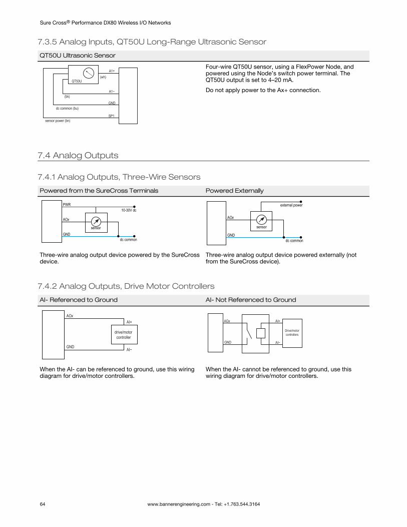
7.3.5 Analog Inputs, QT50U Long-Range Ultrasonic Sensor
QT50U Ultrasonic Sensor
sensor power (bn)
dc common (bu)
(wh)
(bk)
QT50U
A1−
GND
SP1
A1+Four-wire QT50U sensor, using a FlexPower Node, andpowered using the Node’s switch power terminal. TheQT50U output is set to 4–20 mA.
Do not apply power to the Ax+ connection.
7.4 Analog Outputs
7.4.1 Analog Outputs, Three-Wire Sensors
Powered from the SureCross Terminals Powered Externally
AOx
GNDdc common
PWR10-30V dc
sensor
AOx
GNDdc common
external power
sensor
Three-wire analog output device powered by the SureCrossdevice.
Three-wire analog output device powered externally (notfrom the SureCross device).
7.4.2 Analog Outputs, Drive Motor Controllers
AI- Referenced to Ground AI- Not Referenced to Ground
drive/motorcontroller
AOx
GND
AI+
AI−
Drive/motorcontrollers
AOx
GND
AI+
AI−
When the AI- can be referenced to ground, use this wiringdiagram for drive/motor controllers.
When the AI- cannot be referenced to ground, use thiswiring diagram for drive/motor controllers.
Sure Cross® Performance DX80 Wireless I/O Networks
64 www.bannerengineering.com - Tel: +1.763.544.3164
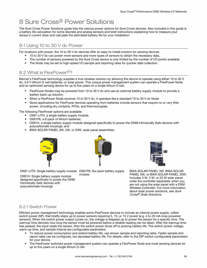
8 Sure Cross® Power SolutionsThe Sure Cross Power Solutions guide lists the various power options for Sure Cross devices. Also included in this guide isa battery life calculation for some discrete and analog sensors and brief instructions explaining how to measure yoursensor's current draw and calculate the estimated battery life for your installation.
8.1 Using 10 to 30 V dc PowerFor locations with power, the 10 to 30 V dc devices offer an easy-to-install solution for sensing devices.
• 10 to 30 V dc can power more sensors and more types of sensors to obtain the necessary data.• The number of sensors powered by the Sure Cross device is only limited by the number of I/O points available.• The Node may be set to high-speed I/O sample and reporting rates for quicker data collection.
8.2 What is FlexPower®?Banner’s FlexPower technology supplies a true wireless solution by allowing the device to operate using either 10 to 30 Vdc, 3.6 V lithium D cell batteries, or solar power. This unique power management system can operate a FlexPower Nodeand an optimized sensing device for up to five years on a single lithium D cell.
• FlexPower Nodes may be powered from 10 to 30 V dc and use an external battery supply module to provide abattery back-up solution.
• When a FlexPower Node receives 10 to 30 V dc, it operates like a standard 10 to 30 V dc Node.• Good applications for FlexPower devices operating from batteries include sensors that require no or very little
power, including dry contacts, RTDs, and thermocouples.
The following FlexPower options are available:• DX81-LITH, a single battery supply module;• DX81P6, a 6-pack of lithium batteries;• DX81H, a single battery supply module designed specifically to power the DX99 Intrinsically Safe devices with
polycarbonate housings; and• BWA-SOLAR PANEL 3W, 5W, or 20W, solar panel assemblies.
DX81-LITH: Single battery supply module
DX81H: Single battery supply moduledesigned specifically to power the DX99Intrinsically Safe devices withpolycarbonate housings
DX81P6: Six-pack battery supplymodule
BWA-SOLAR PANEL 3W, BWA-SOLARPANEL 5W, or BWA-SOLAR PANEL 20W:Includes 3 W, 5 W, or 20 W solar panel;order the controller separately when youare not using the solar panel with a DXMWireless Controller. For more informationabout solar power solutions, see SureCross® Solar Solutions.
8.2.1 Switch PowerEfficient power management technology enables some FlexPower devices to include an internal power supply, calledswitch power (SP), that briefly steps up to power sensors requiring 5, 10, or 15 V power (e.g. 4 to 20 mA loop-poweredsensors). When the switch power output cycles on, the voltage is stepped up to power the sensor for a specific time. Thewarmup time denotes how long the sensor must be powered before a reliable reading can be taken. After the warmup timehas passed, the input reads the sensor, then the switch power shuts off to prolong battery life. The switch power voltage,warm-up time, and sample interval are configurable parameters.
• To reduce power consumption and extend battery life, use slower sample and reporting rates. Faster sample andreport rates can be configured, but decrease battery life. For details, refer to the DIP switch configurable parametersfor your device.
• The FlexPower switched power management system can operate a FlexPower Node and most sensing devices forup to five years on a single lithium D cell.
Sure Cross® Performance DX80 Wireless I/O Networks
www.bannerengineering.com - Tel: +1.763.544.3164 65
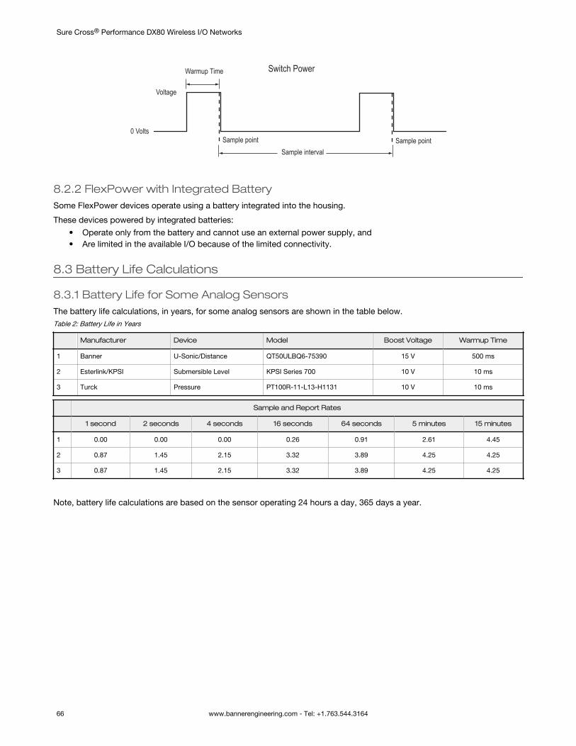
Warmup Time
0 Volts
Switch Power
Sample point Sample pointSample interval
Voltage
8.2.2 FlexPower with Integrated BatterySome FlexPower devices operate using a battery integrated into the housing.
These devices powered by integrated batteries:• Operate only from the battery and cannot use an external power supply, and• Are limited in the available I/O because of the limited connectivity.
8.3 Battery Life Calculations
8.3.1 Battery Life for Some Analog SensorsThe battery life calculations, in years, for some analog sensors are shown in the table below.Table 2: Battery Life in Years
Manufacturer Device Model Boost Voltage Warmup Time
1 Banner U-Sonic/Distance QT50ULBQ6-75390 15 V 500 ms
2 Esterlink/KPSI Submersible Level KPSI Series 700 10 V 10 ms
3 Turck Pressure PT100R-11-L13-H1131 10 V 10 ms
Sample and Report Rates
1 second 2 seconds 4 seconds 16 seconds 64 seconds 5 minutes 15 minutes
1 0.00 0.00 0.00 0.26 0.91 2.61 4.45
2 0.87 1.45 2.15 3.32 3.89 4.25 4.25
3 0.87 1.45 2.15 3.32 3.89 4.25 4.25
Note, battery life calculations are based on the sensor operating 24 hours a day, 365 days a year.
Sure Cross® Performance DX80 Wireless I/O Networks
66 www.bannerengineering.com - Tel: +1.763.544.3164
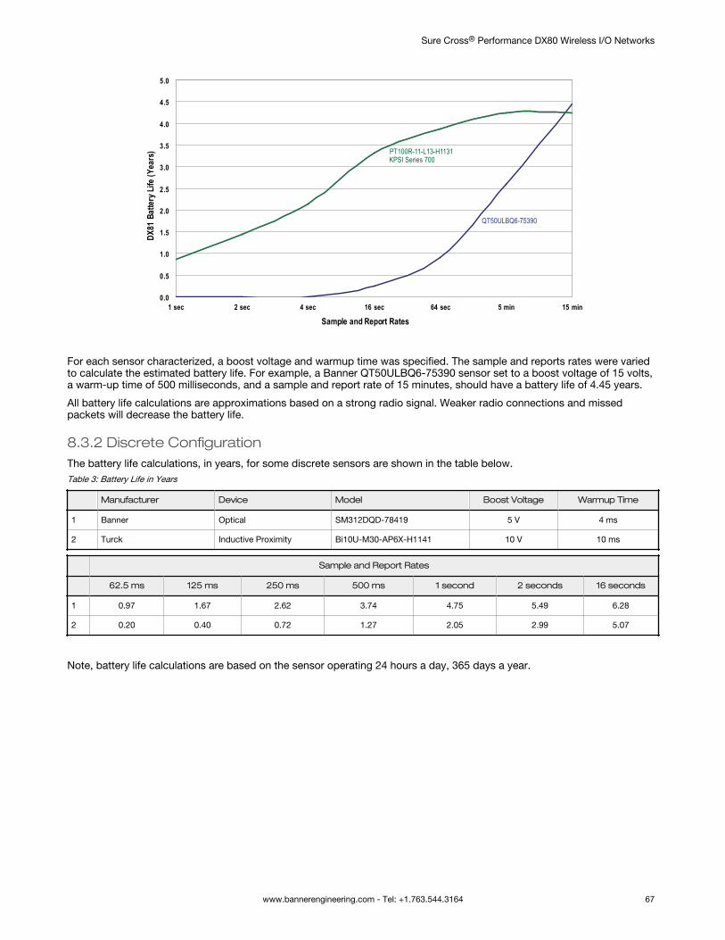
QT50ULBQ6-75390
PT100R-11-L13-H1131KPSI Series 700
0.0
0.5
1.0
1.5
2.0
2.5
3.0
3.5
4.0
4.5
5.0
1 sec 2 sec 4 sec 16 sec 64 sec 5 min 15 min
Sample and Report Rates
DX81
Bat
tery
Life
(Yea
rs)
For each sensor characterized, a boost voltage and warmup time was specified. The sample and reports rates were variedto calculate the estimated battery life. For example, a Banner QT50ULBQ6-75390 sensor set to a boost voltage of 15 volts,a warm-up time of 500 milliseconds, and a sample and report rate of 15 minutes, should have a battery life of 4.45 years.
All battery life calculations are approximations based on a strong radio signal. Weaker radio connections and missedpackets will decrease the battery life.
8.3.2 Discrete ConfigurationThe battery life calculations, in years, for some discrete sensors are shown in the table below.Table 3: Battery Life in Years
Manufacturer Device Model Boost Voltage Warmup Time
1 Banner Optical SM312DQD-78419 5 V 4 ms
2 Turck Inductive Proximity Bi10U-M30-AP6X-H1141 10 V 10 ms
Sample and Report Rates
62.5 ms 125 ms 250 ms 500 ms 1 second 2 seconds 16 seconds
1 0.97 1.67 2.62 3.74 4.75 5.49 6.28
2 0.20 0.40 0.72 1.27 2.05 2.99 5.07
Note, battery life calculations are based on the sensor operating 24 hours a day, 365 days a year.
Sure Cross® Performance DX80 Wireless I/O Networks
www.bannerengineering.com - Tel: +1.763.544.3164 67
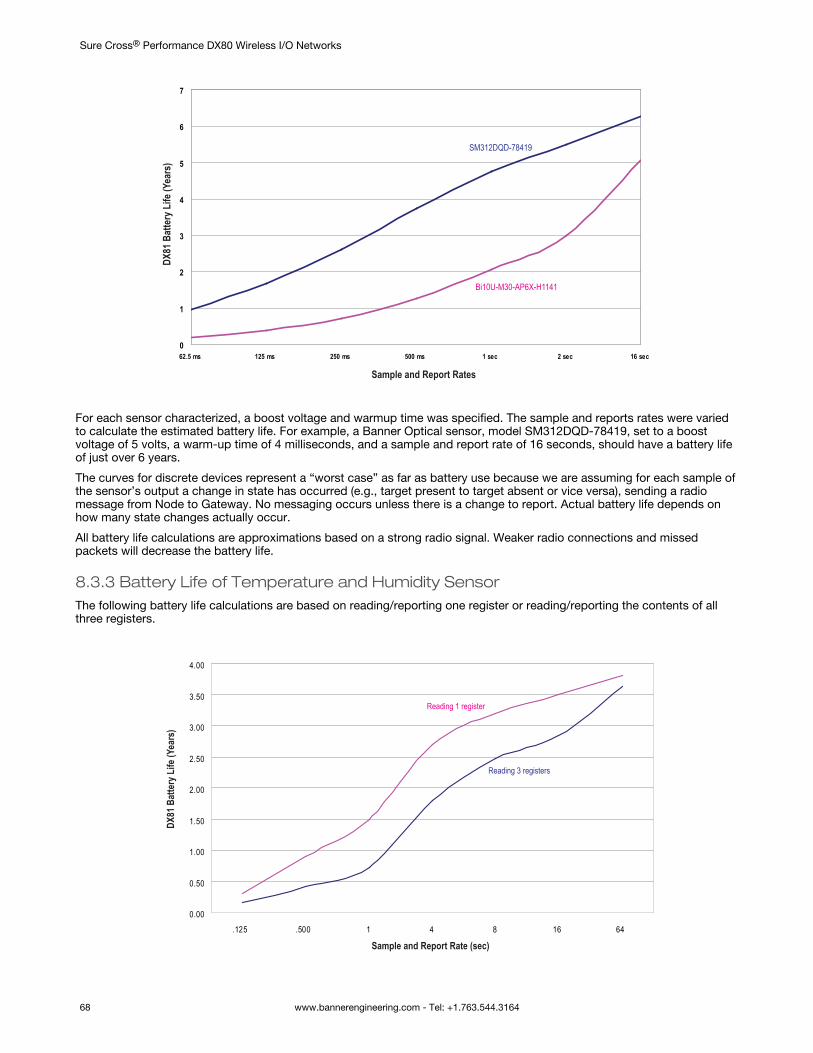
SM312DQD-78419
Bi10U-M30-AP6X-H1141
0
1
2
3
4
5
6
7
62.5 ms 125 ms 250 ms 500 ms 1 sec 2 sec 16 sec
DX81
Bat
tery
Life
(Yea
rs)
Sample and Report Rates
For each sensor characterized, a boost voltage and warmup time was specified. The sample and reports rates were variedto calculate the estimated battery life. For example, a Banner Optical sensor, model SM312DQD-78419, set to a boostvoltage of 5 volts, a warm-up time of 4 milliseconds, and a sample and report rate of 16 seconds, should have a battery lifeof just over 6 years.
The curves for discrete devices represent a “worst case” as far as battery use because we are assuming for each sample ofthe sensor’s output a change in state has occurred (e.g., target present to target absent or vice versa), sending a radiomessage from Node to Gateway. No messaging occurs unless there is a change to report. Actual battery life depends onhow many state changes actually occur.
All battery life calculations are approximations based on a strong radio signal. Weaker radio connections and missedpackets will decrease the battery life.
8.3.3 Battery Life of Temperature and Humidity SensorThe following battery life calculations are based on reading/reporting one register or reading/reporting the contents of allthree registers.
0.00
0.50
1.00
1.50
2.00
2.50
3.00
3.50
4.00
.125 .500 1 4 8 16 64
Reading 1 register
Reading 3 registers
DX81
Bat
tery
Life
(Yea
rs)
Sample and Report Rate (sec)
Sure Cross® Performance DX80 Wireless I/O Networks
68 www.bannerengineering.com - Tel: +1.763.544.3164
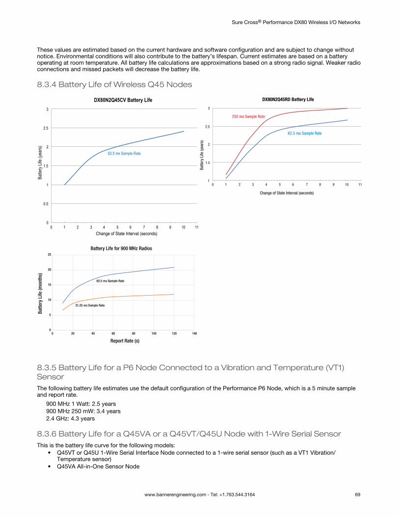
These values are estimated based on the current hardware and software configuration and are subject to change withoutnotice. Environmental conditions will also contribute to the battery’s lifespan. Current estimates are based on a batteryoperating at room temperature. All battery life calculations are approximations based on a strong radio signal. Weaker radioconnections and missed packets will decrease the battery life.
8.3.4 Battery Life of Wireless Q45 Nodes
DX80N2Q45CV Battery Life
Change of State Interval (seconds)
Batte
ry Lif
e (ye
ars)
00
1 2 3 4 5 6 7 8 9 10 11
0.5
1
1.5
2
2.5
3
62.5 ms Sample Rate
DX80N2Q45RD Battery Life
Change of State Interval (seconds)
Batte
ry L
ife (y
ears
)
62.5 ms Sample Rate
250 ms Sample Rate
0 1 2 3 4 5 6 7 8 9 10 111
1.5
2
2.5
3
0
5
10
15
20
25
0 20 40 60 80 100 120 140
Battery Life for 900 MHz Radios
62.5 ms Sample Rate
31.25 ms Sample Rate
Batte
ry L
ife (m
onth
s)
Report Rate (s)
8.3.5 Battery Life for a P6 Node Connected to a Vibration and Temperature (VT1)SensorThe following battery life estimates use the default configuration of the Performance P6 Node, which is a 5 minute sampleand report rate.
900 MHz 1 Watt: 2.5 years900 MHz 250 mW: 3.4 years2.4 GHz: 4.3 years
8.3.6 Battery Life for a Q45VA or a Q45VT/Q45U Node with 1-Wire Serial SensorThis is the battery life curve for the following models:
• Q45VT or Q45U 1-Wire Serial Interface Node connected to a 1-wire serial sensor (such as a VT1 Vibration/Temperature sensor)
• Q45VA All-in-One Sensor Node
Sure Cross® Performance DX80 Wireless I/O Networks
www.bannerengineering.com - Tel: +1.763.544.3164 69
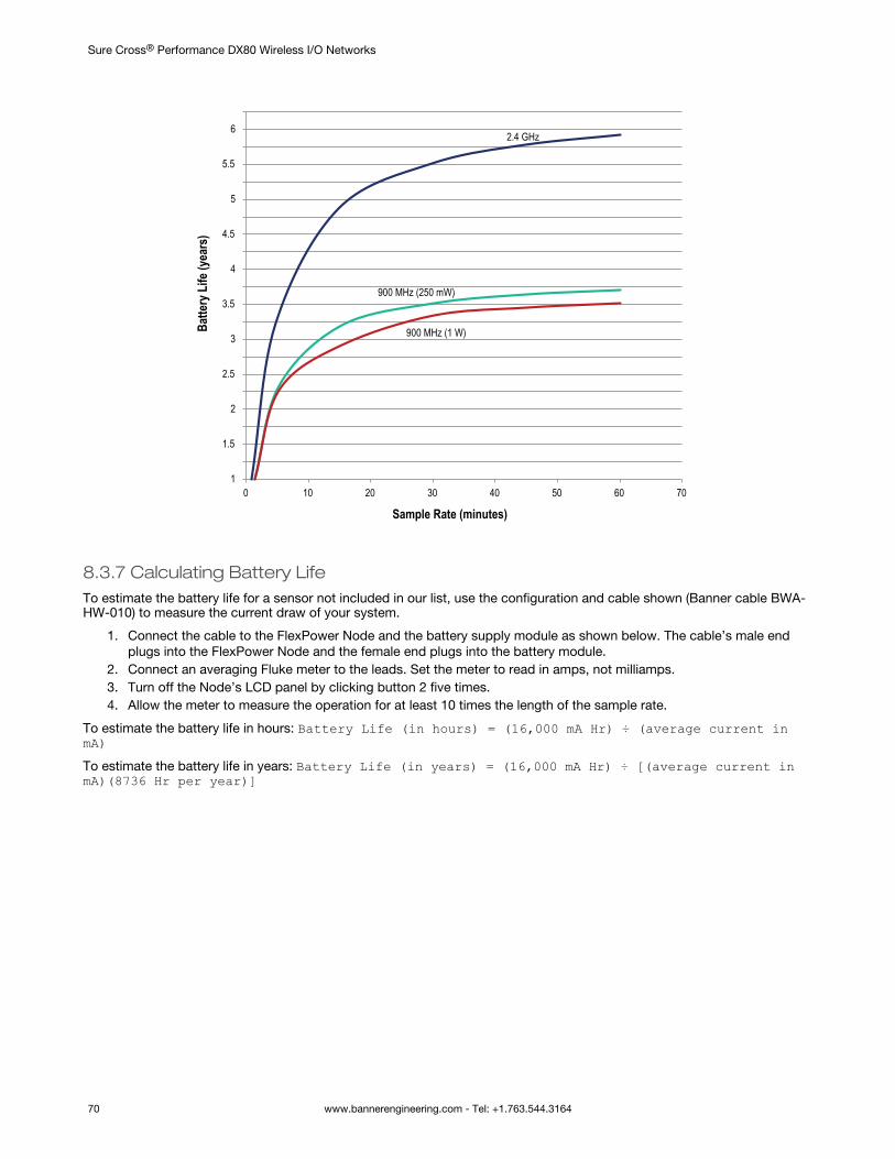
1
1.5
2
2.5
3
3.5
4
4.5
5
5.5
6
0 10 20 30 40 50 60 70
2.4 GHz
900 MHz (250 mW)
900 MHz (1 W)
Sample Rate (minutes)
Batte
ry L
ife (y
ears
)
8.3.7 Calculating Battery LifeTo estimate the battery life for a sensor not included in our list, use the configuration and cable shown (Banner cable BWA-HW-010) to measure the current draw of your system.
1. Connect the cable to the FlexPower Node and the battery supply module as shown below. The cable’s male endplugs into the FlexPower Node and the female end plugs into the battery module.
2. Connect an averaging Fluke meter to the leads. Set the meter to read in amps, not milliamps.3. Turn off the Node’s LCD panel by clicking button 2 five times.4. Allow the meter to measure the operation for at least 10 times the length of the sample rate.
To estimate the battery life in hours: Battery Life (in hours) = (16,000 mA Hr) ÷ (average current inmA)To estimate the battery life in years: Battery Life (in years) = (16,000 mA Hr) ÷ [(average current inmA)(8736 Hr per year)]
Sure Cross® Performance DX80 Wireless I/O Networks
70 www.bannerengineering.com - Tel: +1.763.544.3164
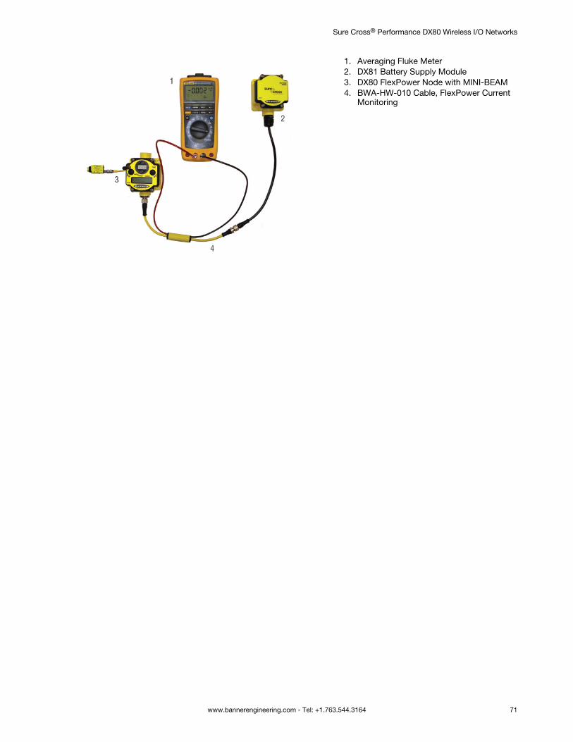
1. Averaging Fluke Meter2. DX81 Battery Supply Module3. DX80 FlexPower Node with MINI-BEAM4. BWA-HW-010 Cable, FlexPower Current
Monitoring
Sure Cross® Performance DX80 Wireless I/O Networks
www.bannerengineering.com - Tel: +1.763.544.3164 71
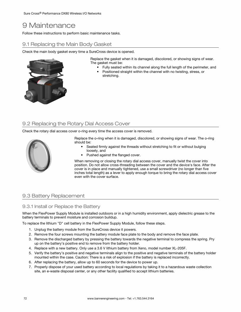
9 MaintenanceFollow these instructions to perform basic maintenance tasks.
9.1 Replacing the Main Body GasketCheck the main body gasket every time a SureCross device is opened.
Replace the gasket when it is damaged, discolored, or showing signs of wear.The gasket must be:
• Fully seated within its channel along the full length of the perimeter, and• Positioned straight within the channel with no twisting, stress, or
stretching.
9.2 Replacing the Rotary Dial Access CoverCheck the rotary dial access cover o-ring every time the access cover is removed.
Replace the o-ring when it is damaged, discolored, or showing signs of wear. The o-ringshould be:
• Seated firmly against the threads without stretching to fit or without bulgingloosely, and
• Pushed against the flanged cover.
When removing or closing the rotary dial access cover, manually twist the cover intoposition. Do not allow cross-threading between the cover and the device's face. After thecover is in place and manually tightened, use a small screwdriver (no longer than fiveinches total length) as a lever to apply enough torque to bring the rotary dial access covereven with the cover surface.
9.3 Battery Replacement
9.3.1 Install or Replace the BatteryWhen the FlexPower Supply Module is installed outdoors or in a high humidity environment, apply dielectric grease to thebattery terminals to prevent moisture and corrosion buildup.
To replace the lithium "D" cell battery in the FlexPower Supply Module, follow these steps.
1. Unplug the battery module from the SureCross device it powers.2. Remove the four screws mounting the battery module face plate to the body and remove the face plate.3. Remove the discharged battery by pressing the battery towards the negative terminal to compress the spring. Pry
up on the battery’s positive end to remove from the battery holder.4. Replace with a new battery. Only use a 3.6 V lithium battery from Xeno, model number XL-205F.5. Verify the battery’s positive and negative terminals align to the positive and negative terminals of the battery holder
mounted within the case. Caution: There is a risk of explosion if the battery is replaced incorrectly.6. After replacing the battery, allow up to 60 seconds for the device to power up.7. Properly dispose of your used battery according to local regulations by taking it to a hazardous waste collection
site, an e-waste disposal center, or any other facility qualified to accept lithium batteries.
Sure Cross® Performance DX80 Wireless I/O Networks
72 www.bannerengineering.com - Tel: +1.763.544.3164
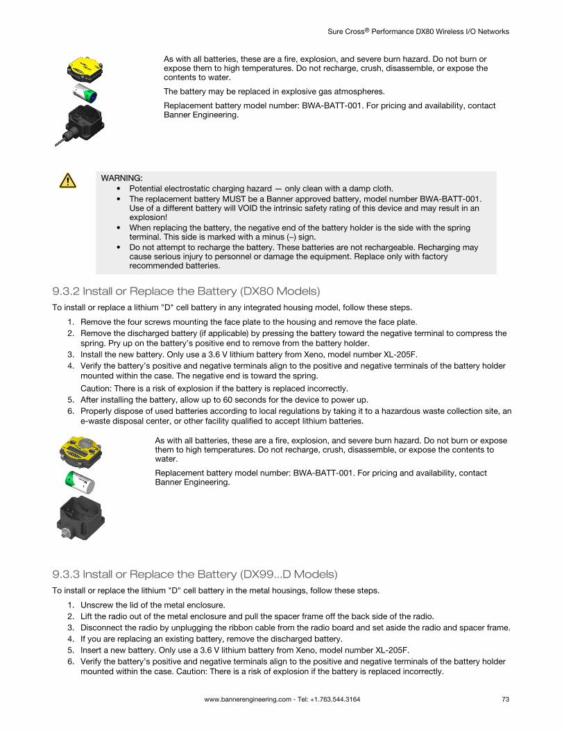
As with all batteries, these are a fire, explosion, and severe burn hazard. Do not burn orexpose them to high temperatures. Do not recharge, crush, disassemble, or expose thecontents to water.
The battery may be replaced in explosive gas atmospheres.
Replacement battery model number: BWA-BATT-001. For pricing and availability, contactBanner Engineering.
WARNING:• Potential electrostatic charging hazard — only clean with a damp cloth.• The replacement battery MUST be a Banner approved battery, model number BWA-BATT-001.
Use of a different battery will VOID the intrinsic safety rating of this device and may result in anexplosion!
• When replacing the battery, the negative end of the battery holder is the side with the springterminal. This side is marked with a minus (−) sign.
• Do not attempt to recharge the battery. These batteries are not rechargeable. Recharging maycause serious injury to personnel or damage the equipment. Replace only with factoryrecommended batteries.
9.3.2 Install or Replace the Battery (DX80 Models)To install or replace a lithium "D" cell battery in any integrated housing model, follow these steps.
1. Remove the four screws mounting the face plate to the housing and remove the face plate.2. Remove the discharged battery (if applicable) by pressing the battery toward the negative terminal to compress the
spring. Pry up on the battery’s positive end to remove from the battery holder.3. Install the new battery. Only use a 3.6 V lithium battery from Xeno, model number XL-205F.4. Verify the battery’s positive and negative terminals align to the positive and negative terminals of the battery holder
mounted within the case. The negative end is toward the spring.
Caution: There is a risk of explosion if the battery is replaced incorrectly.5. After installing the battery, allow up to 60 seconds for the device to power up.6. Properly dispose of used batteries according to local regulations by taking it to a hazardous waste collection site, an
e-waste disposal center, or other facility qualified to accept lithium batteries.
As with all batteries, these are a fire, explosion, and severe burn hazard. Do not burn or exposethem to high temperatures. Do not recharge, crush, disassemble, or expose the contents towater.
Replacement battery model number: BWA-BATT-001. For pricing and availability, contactBanner Engineering.
9.3.3 Install or Replace the Battery (DX99...D Models)To install or replace the lithium "D" cell battery in the metal housings, follow these steps.
1. Unscrew the lid of the metal enclosure.2. Lift the radio out of the metal enclosure and pull the spacer frame off the back side of the radio.3. Disconnect the radio by unplugging the ribbon cable from the radio board and set aside the radio and spacer frame.4. If you are replacing an existing battery, remove the discharged battery.5. Insert a new battery. Only use a 3.6 V lithium battery from Xeno, model number XL-205F.6. Verify the battery’s positive and negative terminals align to the positive and negative terminals of the battery holder
mounted within the case. Caution: There is a risk of explosion if the battery is replaced incorrectly.
Sure Cross® Performance DX80 Wireless I/O Networks
www.bannerengineering.com - Tel: +1.763.544.3164 73
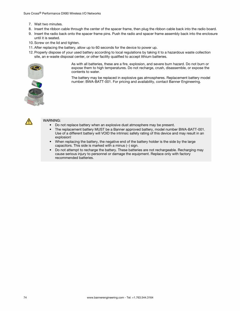
7. Wait two minutes.8. Insert the ribbon cable through the center of the spacer frame, then plug the ribbon cable back into the radio board.9. Insert the radio back onto the spacer frame pins. Push the radio and spacer frame assembly back into the enclosure
until it is seated.10. Screw on the lid and tighten.11. After replacing the battery, allow up to 60 seconds for the device to power up.12. Properly dispose of your used battery according to local regulations by taking it to a hazardous waste collection
site, an e-waste disposal center, or other facility qualified to accept lithium batteries.
As with all batteries, these are a fire, explosion, and severe burn hazard. Do not burn orexpose them to high temperatures. Do not recharge, crush, disassemble, or expose thecontents to water.
The battery may be replaced in explosive gas atmospheres. Replacement battery modelnumber: BWA-BATT-001. For pricing and availability, contact Banner Engineering.
WARNING:• Do not replace battery when an explosive dust atmosphere may be present.• The replacement battery MUST be a Banner approved battery, model number BWA-BATT-001.
Use of a different battery will VOID the intrinsic safety rating of this device and may result in anexplosion!
• When replacing the battery, the negative end of the battery holder is the side by the largecapacitors. This side is marked with a minus (−) sign.
• Do not attempt to recharge the battery. These batteries are not rechargeable. Recharging maycause serious injury to personnel or damage the equipment. Replace only with factoryrecommended batteries.
Sure Cross® Performance DX80 Wireless I/O Networks
74 www.bannerengineering.com - Tel: +1.763.544.3164
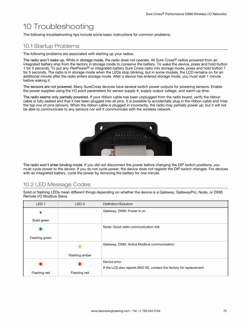
10 TroubleshootingThe following troubleshooting tips include some basic instructions for common problems.
10.1 Startup ProblemsThe following problems are associated with starting up your radios.
The radio won't wake up. While in storage mode, the radio does not operate. All Sure Cross® radios powered from anintegrated battery ship from the factory in storage mode to conserve the battery. To wake the device, press and hold button1 for 5 seconds. To put any FlexPower® or integrated battery Sure Cross radio into storage mode, press and hold button 1for 5 seconds. The radio is in storage mode when the LEDs stop blinking, but in some models, the LCD remains on for anadditional minute after the radio enters storage mode. After a device has entered storage mode, you must wait 1 minutebefore waking it.
The sensors are not powered. Many SureCross devices have several switch power outputs for powering sensors. Enablethe power supplies using the I/O point parameters for sensor supply #, supply output voltage, and warm-up time.
The radio seems only partially powered. If your ribbon cable has been unplugged from the radio board, verify the ribboncable is fully seated and that it has been plugged into all pins. It is possible to accidentally plug in the ribbon cable and missthe top row of pins (shown). When the ribbon cable is plugged in incorrectly, the radio may partially power up, but it will notbe able to communicate to any sensors nor will it communicate with the wireless network.
The radio won't enter binding mode. If you did not disconnect the power before changing the DIP switch positions, youmust cycle power to the device. If you do not cycle power, the device does not register the DIP switch changes. For deviceswith an integrated battery, cycle the power by removing the battery for one minute.
10.2 LED Message CodesSolid or flashing LEDs mean different things depending on whether the device is a Gateway, GatewayPro, Node, or DX85Remote I/O Modbus Slave.
LED 1 LED 2 Definition/Solution
Solid green
Gateway, DX85: Power is on
Flashing green
Node: Good radio communication link
Flashing amber
Gateway, DX85: Active Modbus communication
Flashing red Flashing red
Device error.
If the LCD also reports BAD EE, contact the factory for replacement.
Sure Cross® Performance DX80 Wireless I/O Networks
www.bannerengineering.com - Tel: +1.763.544.3164 75
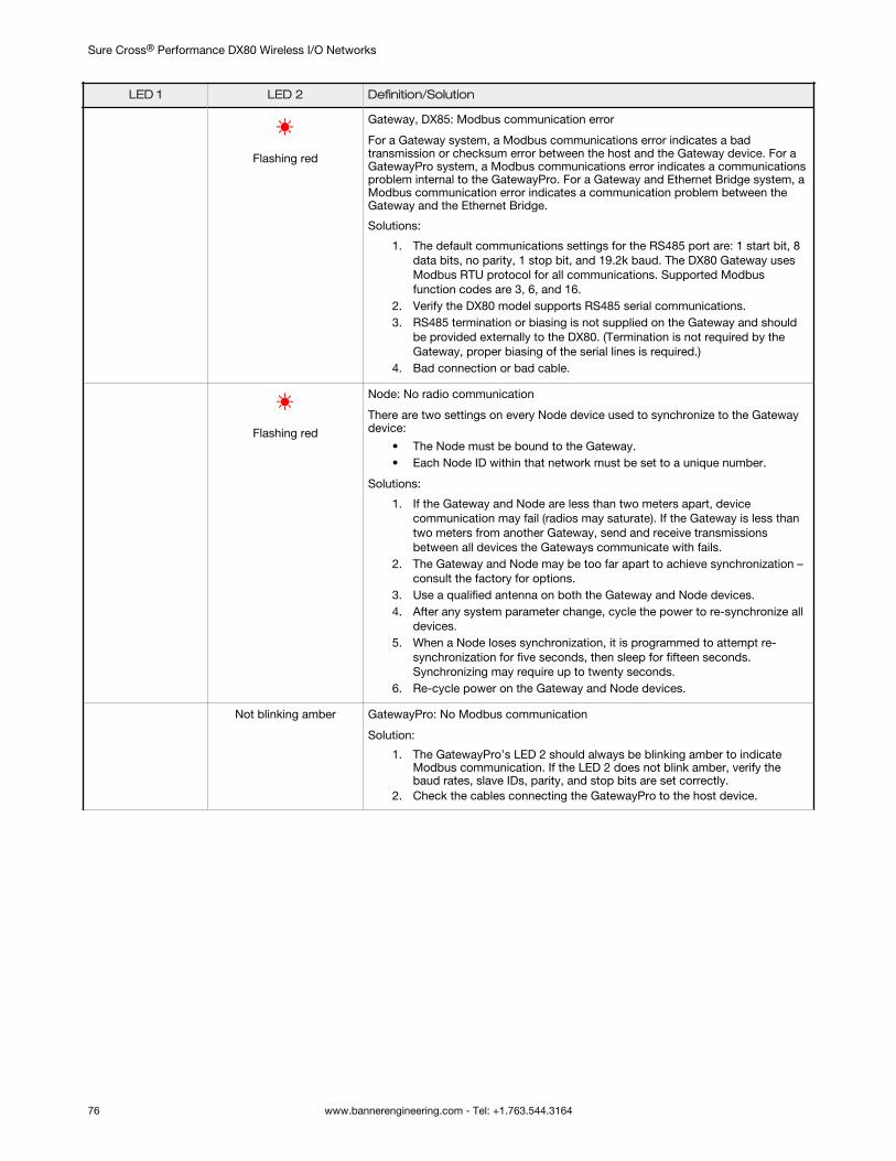
LED 1 LED 2 Definition/Solution
Flashing red
Gateway, DX85: Modbus communication error
For a Gateway system, a Modbus communications error indicates a badtransmission or checksum error between the host and the Gateway device. For aGatewayPro system, a Modbus communications error indicates a communicationsproblem internal to the GatewayPro. For a Gateway and Ethernet Bridge system, aModbus communication error indicates a communication problem between theGateway and the Ethernet Bridge.
Solutions:
1. The default communications settings for the RS485 port are: 1 start bit, 8data bits, no parity, 1 stop bit, and 19.2k baud. The DX80 Gateway usesModbus RTU protocol for all communications. Supported Modbusfunction codes are 3, 6, and 16.
2. Verify the DX80 model supports RS485 serial communications.3. RS485 termination or biasing is not supplied on the Gateway and should
be provided externally to the DX80. (Termination is not required by theGateway, proper biasing of the serial lines is required.)
4. Bad connection or bad cable.
Flashing red
Node: No radio communication
There are two settings on every Node device used to synchronize to the Gatewaydevice:
• The Node must be bound to the Gateway.• Each Node ID within that network must be set to a unique number.
Solutions:
1. If the Gateway and Node are less than two meters apart, devicecommunication may fail (radios may saturate). If the Gateway is less thantwo meters from another Gateway, send and receive transmissionsbetween all devices the Gateways communicate with fails.
2. The Gateway and Node may be too far apart to achieve synchronization –consult the factory for options.
3. Use a qualified antenna on both the Gateway and Node devices.4. After any system parameter change, cycle the power to re-synchronize all
devices.5. When a Node loses synchronization, it is programmed to attempt re-
synchronization for five seconds, then sleep for fifteen seconds.Synchronizing may require up to twenty seconds.
6. Re-cycle power on the Gateway and Node devices.
Not blinking amber GatewayPro: No Modbus communication
Solution:
1. The GatewayPro’s LED 2 should always be blinking amber to indicateModbus communication. If the LED 2 does not blink amber, verify thebaud rates, slave IDs, parity, and stop bits are set correctly.
2. Check the cables connecting the GatewayPro to the host device.
Sure Cross® Performance DX80 Wireless I/O Networks
76 www.bannerengineering.com - Tel: +1.763.544.3164
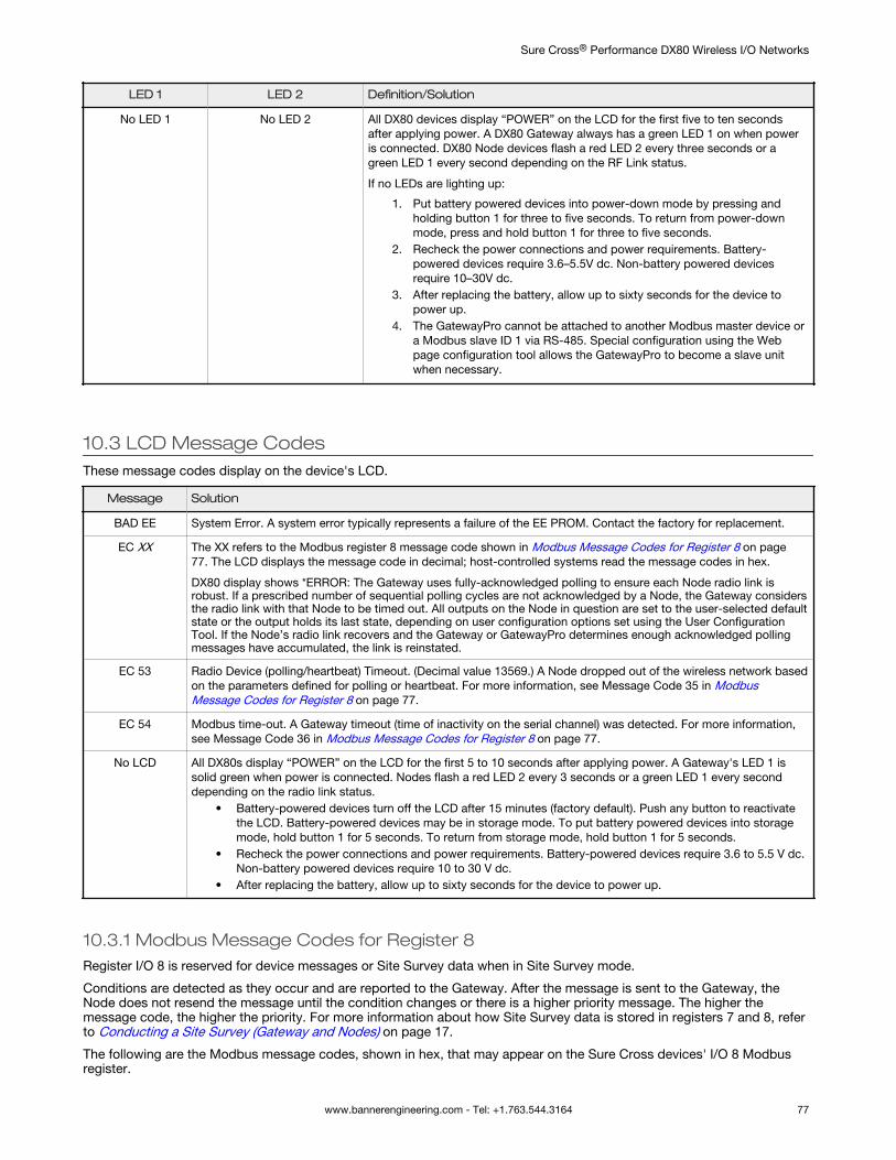
LED 1 LED 2 Definition/Solution
No LED 1 No LED 2 All DX80 devices display “POWER” on the LCD for the first five to ten secondsafter applying power. A DX80 Gateway always has a green LED 1 on when poweris connected. DX80 Node devices flash a red LED 2 every three seconds or agreen LED 1 every second depending on the RF Link status.
If no LEDs are lighting up:
1. Put battery powered devices into power-down mode by pressing andholding button 1 for three to five seconds. To return from power-downmode, press and hold button 1 for three to five seconds.
2. Recheck the power connections and power requirements. Battery-powered devices require 3.6–5.5V dc. Non-battery powered devicesrequire 10–30V dc.
3. After replacing the battery, allow up to sixty seconds for the device topower up.
4. The GatewayPro cannot be attached to another Modbus master device ora Modbus slave ID 1 via RS-485. Special configuration using the Webpage configuration tool allows the GatewayPro to become a slave unitwhen necessary.
10.3 LCD Message CodesThese message codes display on the device's LCD.
Message Solution
BAD EE System Error. A system error typically represents a failure of the EE PROM. Contact the factory for replacement.
EC XX The XX refers to the Modbus register 8 message code shown in Modbus Message Codes for Register 8 on page77. The LCD displays the message code in decimal; host-controlled systems read the message codes in hex.
DX80 display shows *ERROR: The Gateway uses fully-acknowledged polling to ensure each Node radio link isrobust. If a prescribed number of sequential polling cycles are not acknowledged by a Node, the Gateway considersthe radio link with that Node to be timed out. All outputs on the Node in question are set to the user-selected defaultstate or the output holds its last state, depending on user configuration options set using the User ConfigurationTool. If the Node’s radio link recovers and the Gateway or GatewayPro determines enough acknowledged pollingmessages have accumulated, the link is reinstated.
EC 53 Radio Device (polling/heartbeat) Timeout. (Decimal value 13569.) A Node dropped out of the wireless network basedon the parameters defined for polling or heartbeat. For more information, see Message Code 35 in ModbusMessage Codes for Register 8 on page 77.
EC 54 Modbus time-out. A Gateway timeout (time of inactivity on the serial channel) was detected. For more information,see Message Code 36 in Modbus Message Codes for Register 8 on page 77.
No LCD All DX80s display “POWER” on the LCD for the first 5 to 10 seconds after applying power. A Gateway's LED 1 issolid green when power is connected. Nodes flash a red LED 2 every 3 seconds or a green LED 1 every seconddepending on the radio link status.
• Battery-powered devices turn off the LCD after 15 minutes (factory default). Push any button to reactivatethe LCD. Battery-powered devices may be in storage mode. To put battery powered devices into storagemode, hold button 1 for 5 seconds. To return from storage mode, hold button 1 for 5 seconds.
• Recheck the power connections and power requirements. Battery-powered devices require 3.6 to 5.5 V dc.Non-battery powered devices require 10 to 30 V dc.
• After replacing the battery, allow up to sixty seconds for the device to power up.
10.3.1 Modbus Message Codes for Register 8Register I/O 8 is reserved for device messages or Site Survey data when in Site Survey mode.
Conditions are detected as they occur and are reported to the Gateway. After the message is sent to the Gateway, theNode does not resend the message until the condition changes or there is a higher priority message. The higher themessage code, the higher the priority. For more information about how Site Survey data is stored in registers 7 and 8, referto Conducting a Site Survey (Gateway and Nodes) on page 17.
The following are the Modbus message codes, shown in hex, that may appear on the Sure Cross devices' I/O 8 Modbusregister.
Sure Cross® Performance DX80 Wireless I/O Networks
www.bannerengineering.com - Tel: +1.763.544.3164 77
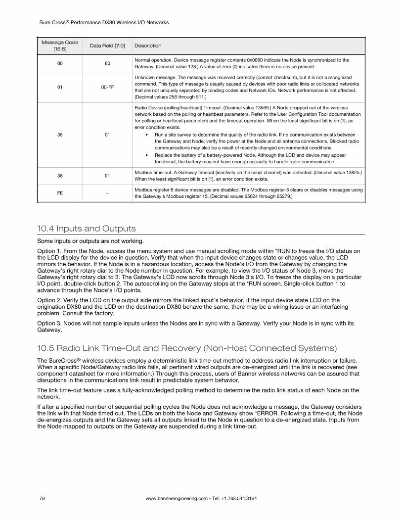
Message Code[15:8]
Data Field [7:0] Description
00 80Normal operation. Device message register contents 0x0080 indicate the Node is synchronized to theGateway. (Decimal value 128.) A value of zero (0) indicates there is no device present.
01 00-FF
Unknown message. The message was received correctly (correct checksum), but it is not a recognizedcommand. This type of message is usually caused by devices with poor radio links or collocated networksthat are not uniquely separated by binding codes and Network IDs. Network performance is not affected.(Decimal values 256 through 511.)
35 01
Radio Device (polling/heartbeat) Timeout. (Decimal value 13569.) A Node dropped out of the wirelessnetwork based on the polling or heartbeat parameters. Refer to the User Configuration Tool documentationfor polling or heartbeat parameters and the timeout operation. When the least significant bit is on (1), anerror condition exists.
• Run a site survey to determine the quality of the radio link. If no communication exists betweenthe Gateway and Node, verify the power at the Node and all antenna connections. Blocked radiocommunications may also be a result of recently changed environmental conditions.
• Replace the battery of a battery-powered Node. Although the LCD and device may appearfunctional, the battery may not have enough capacity to handle radio communication.
36 01Modbus time-out. A Gateway timeout (inactivity on the serial channel) was detected. (Decimal value 13825.)When the least significant bit is on (1), an error condition exists.
FE --Modbus register 8 device messages are disabled. The Modbus register 8 clears or disables messages usingthe Gateway’s Modbus register 15. (Decimal values 65024 through 65279.)
10.4 Inputs and OutputsSome inputs or outputs are not working.
Option 1. From the Node, access the menu system and use manual scrolling mode within *RUN to freeze the I/O status onthe LCD display for the device in question. Verify that when the input device changes state or changes value, the LCDmirrors the behavior. If the Node is in a hazardous location, access the Node's I/O from the Gateway by changing theGateway's right rotary dial to the Node number in question. For example, to view the I/O status of Node 3, move theGateway's right rotary dial to 3. The Gateway's LCD now scrolls through Node 3's I/O. To freeze the display on a particularI/O point, double-click button 2. The autoscrolling on the Gateway stops at the *RUN screen. Single-click button 1 toadvance through the Node's I/O points.
Option 2. Verify the LCD on the output side mirrors the linked input’s behavior. If the input device state LCD on theorigination DX80 and the LCD on the destination DX80 behave the same, there may be a wiring issue or an interfacingproblem. Consult the factory.
Option 3. Nodes will not sample inputs unless the Nodes are in sync with a Gateway. Verify your Node is in sync with itsGateway.
10.5 Radio Link Time-Out and Recovery (Non-Host Connected Systems)The SureCross® wireless devices employ a deterministic link time-out method to address radio link interruption or failure.When a specific Node/Gateway radio link fails, all pertinent wired outputs are de-energized until the link is recovered (seecomponent datasheet for more information.) Through this process, users of Banner wireless networks can be assured thatdisruptions in the communications link result in predictable system behavior.
The link time-out feature uses a fully-acknowledged polling method to determine the radio link status of each Node on thenetwork.
If after a specified number of sequential polling cycles the Node does not acknowledge a message, the Gateway considersthe link with that Node timed out. The LCDs on both the Node and Gateway show *ERROR. Following a time-out, the Nodede-energizes outputs and the Gateway sets all outputs linked to the Node in question to a de-energized state. Inputs fromthe Node mapped to outputs on the Gateway are suspended during a link time-out.
Sure Cross® Performance DX80 Wireless I/O Networks
78 www.bannerengineering.com - Tel: +1.763.544.3164
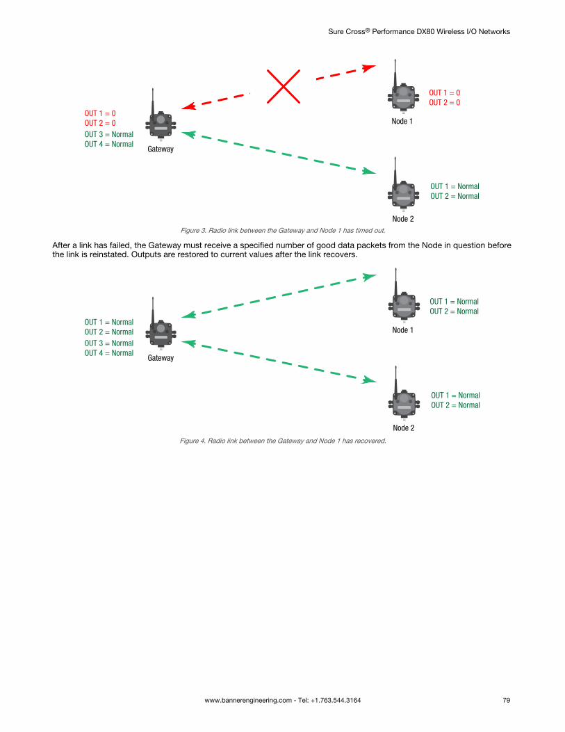
Gateway
Node 1
Node 2
OUT 1 = 0OUT 2 = 0
OUT 1 = NormalOUT 2 = Normal
OUT 1 = 0OUT 2 = 0OUT 3 = NormalOUT 4 = Normal
Figure 3. Radio link between the Gateway and Node 1 has timed out.
After a link has failed, the Gateway must receive a specified number of good data packets from the Node in question beforethe link is reinstated. Outputs are restored to current values after the link recovers.
Gateway
Node 1
Node 2
OUT 1 = NormalOUT 2 = Normal
OUT 1 = NormalOUT 2 = Normal
OUT 1 = NormalOUT 2 = NormalOUT 3 = NormalOUT 4 = Normal
Figure 4. Radio link between the Gateway and Node 1 has recovered.
Sure Cross® Performance DX80 Wireless I/O Networks
www.bannerengineering.com - Tel: +1.763.544.3164 79
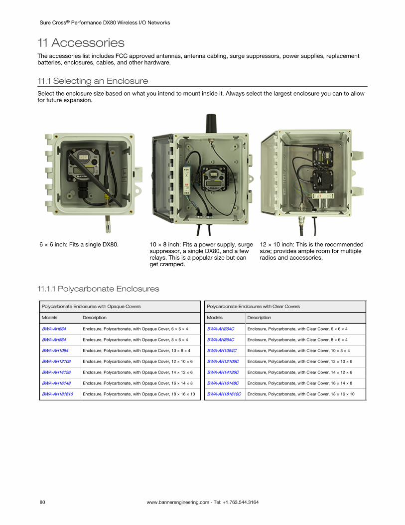
11 AccessoriesThe accessories list includes FCC approved antennas, antenna cabling, surge suppressors, power supplies, replacementbatteries, enclosures, cables, and other hardware.
11.1 Selecting an EnclosureSelect the enclosure size based on what you intend to mount inside it. Always select the largest enclosure you can to allowfor future expansion.
6 × 6 inch: Fits a single DX80. 10 × 8 inch: Fits a power supply, surgesuppressor, a single DX80, and a fewrelays. This is a popular size but canget cramped.
12 × 10 inch: This is the recommendedsize; provides ample room for multipleradios and accessories.
11.1.1 Polycarbonate Enclosures
Polycarbonate Enclosures with Opaque Covers
Models Description
BWA-AH664 Enclosure, Polycarbonate, with Opaque Cover, 6 × 6 × 4
BWA-AH864 Enclosure, Polycarbonate, with Opaque Cover, 8 × 6 × 4
BWA-AH1084 Enclosure, Polycarbonate, with Opaque Cover, 10 × 8 × 4
BWA-AH12106 Enclosure, Polycarbonate, with Opaque Cover, 12 × 10 × 6
BWA-AH14126 Enclosure, Polycarbonate, with Opaque Cover, 14 × 12 × 6
BWA-AH16148 Enclosure, Polycarbonate, with Opaque Cover, 16 × 14 × 8
BWA-AH181610 Enclosure, Polycarbonate, with Opaque Cover, 18 × 16 × 10
Polycarbonate Enclosures with Clear Covers
Models Description
BWA-AH664C Enclosure, Polycarbonate, with Clear Cover, 6 × 6 × 4
BWA-AH864C Enclosure, Polycarbonate, with Clear Cover, 8 × 6 × 4
BWA-AH1084C Enclosure, Polycarbonate, with Clear Cover, 10 × 8 × 4
BWA-AH12106C Enclosure, Polycarbonate, with Clear Cover, 12 × 10 × 6
BWA-AH14126C Enclosure, Polycarbonate, with Clear Cover, 14 × 12 × 6
BWA-AH16148C Enclosure, Polycarbonate, with Clear Cover, 16 × 14 × 8
BWA-AH181610C Enclosure, Polycarbonate, with Clear Cover, 18 × 16 × 10
Sure Cross® Performance DX80 Wireless I/O Networks
80 www.bannerengineering.com - Tel: +1.763.544.3164
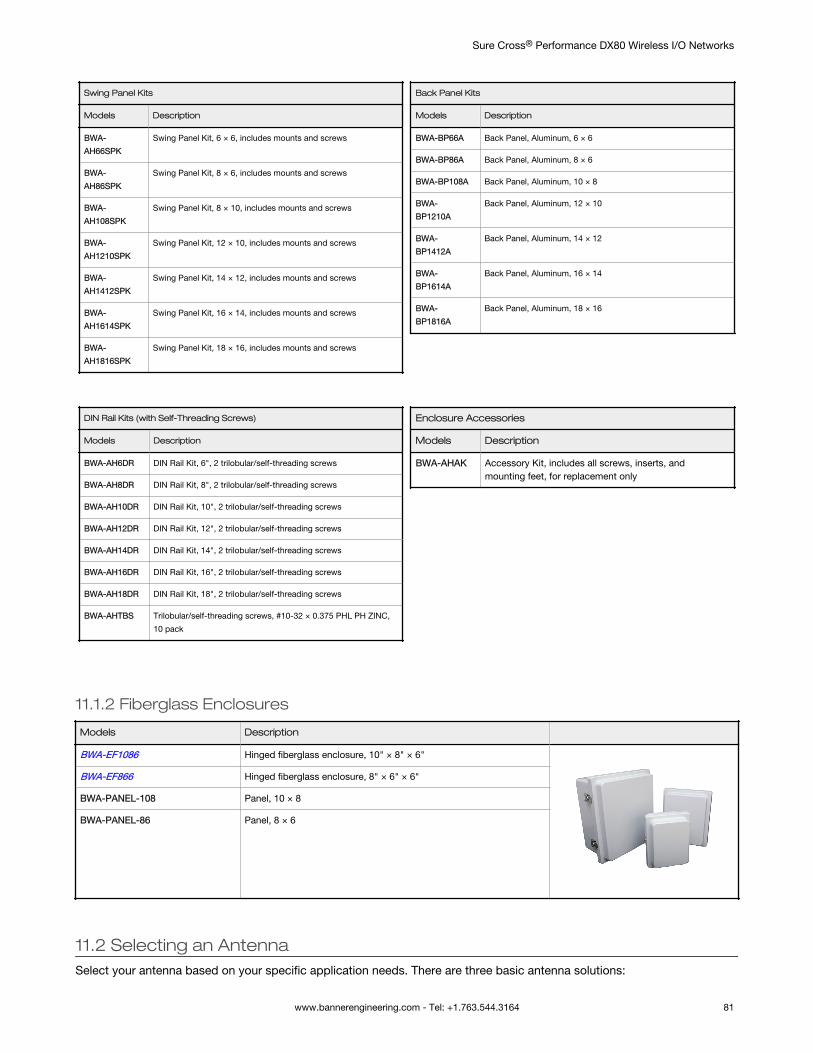
Swing Panel Kits
Models Description
BWA-
AH66SPK
Swing Panel Kit, 6 × 6, includes mounts and screws
BWA-
AH86SPK
Swing Panel Kit, 8 × 6, includes mounts and screws
BWA-
AH108SPK
Swing Panel Kit, 8 × 10, includes mounts and screws
BWA-
AH1210SPK
Swing Panel Kit, 12 × 10, includes mounts and screws
BWA-
AH1412SPK
Swing Panel Kit, 14 × 12, includes mounts and screws
BWA-
AH1614SPK
Swing Panel Kit, 16 × 14, includes mounts and screws
BWA-
AH1816SPK
Swing Panel Kit, 18 × 16, includes mounts and screws
Back Panel Kits
Models Description
BWA-BP66A Back Panel, Aluminum, 6 × 6
BWA-BP86A Back Panel, Aluminum, 8 × 6
BWA-BP108A Back Panel, Aluminum, 10 × 8
BWA-
BP1210A
Back Panel, Aluminum, 12 × 10
BWA-
BP1412A
Back Panel, Aluminum, 14 × 12
BWA-
BP1614A
Back Panel, Aluminum, 16 × 14
BWA-
BP1816A
Back Panel, Aluminum, 18 × 16
DIN Rail Kits (with Self-Threading Screws)
Models Description
BWA-AH6DR DIN Rail Kit, 6", 2 trilobular/self-threading screws
BWA-AH8DR DIN Rail Kit, 8", 2 trilobular/self-threading screws
BWA-AH10DR DIN Rail Kit, 10", 2 trilobular/self-threading screws
BWA-AH12DR DIN Rail Kit, 12", 2 trilobular/self-threading screws
BWA-AH14DR DIN Rail Kit, 14", 2 trilobular/self-threading screws
BWA-AH16DR DIN Rail Kit, 16", 2 trilobular/self-threading screws
BWA-AH18DR DIN Rail Kit, 18", 2 trilobular/self-threading screws
BWA-AHTBS Trilobular/self-threading screws, #10-32 × 0.375 PHL PH ZINC,
10 pack
Enclosure Accessories
Models Description
BWA-AHAK Accessory Kit, includes all screws, inserts, andmounting feet, for replacement only
11.1.2 Fiberglass Enclosures
Models Description
BWA-EF1086 Hinged fiberglass enclosure, 10" × 8" × 6"
BWA-EF866 Hinged fiberglass enclosure, 8" × 6" × 6"
BWA-PANEL-108 Panel, 10 × 8
BWA-PANEL-86 Panel, 8 × 6
11.2 Selecting an AntennaSelect your antenna based on your specific application needs. There are three basic antenna solutions:
Sure Cross® Performance DX80 Wireless I/O Networks
www.bannerengineering.com - Tel: +1.763.544.3164 81
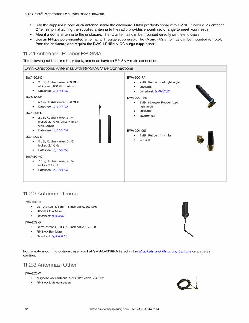
• Use the supplied rubber duck antenna inside the enclosure. DX80 products come with a 2 dBi rubber duck antenna.Often simply attaching the supplied antenna to the radio provides enough radio range to meet your needs.
• Mount a dome antenna to the enclosure. The -D antennas can be mounted directly on the enclosure.• Use an N-type pole-mounted antenna, with surge suppressor. The -A and -AS antennas can be mounted remotely
from the enclosure and require the BWC-LFNBMN-DC surge suppressor.
11.2.1 Antennas: Rubber RP-SMAThe following rubber, or rubber duck, antennas have an RP-SMA male connection.
Omni-Directional Antennas with RP-SMA Male Connections
BWA-9O2-C
• 2 dBi, Rubber swivel, 900 MHz(ships with 900 MHz radios)
• Datasheet: b_3145120
BWA-9O5-C
• 5 dBi, Rubber swivel, 900 MHz
• Datasheet: b_3145123
BWA-2O2-C
• 2 dBi, Rubber swivel, 3 1/4inches, 2.4 GHz (ships with 2.4GHz radios)
• Datasheet: b_3145114
BWA-2O5-C
• 5 dBi, Rubber swivel, 6 1/2inches, 2.4 GHz
• Datasheet: b_3145116
BWA-2O7-C
• 7 dBi, Rubber swivel, 9 1/4inches, 2.4 GHz
• Datasheet: b_3145118
BWA-9O2-RA
• 2 dBi, Rubber fixed right angle
• 900 MHz
• Datasheet: b_4162828
BWA-9O2-RA2
• 2 dBi 1/2-wave, Rubber fixedright angle
• 900 MHz
• 160 mm tall
BWA-2O1-001
• 1 dBi, Rubber, 1 inch tall
• 2.4 GHz
11.2.2 Antennas: Dome
BWA-9O2-D
• Dome antenna, 2 dBi, 18-inch cable, 900 MHz
• RP-SMA Box Mount
• Datasheet: b_314512
BWA-2O2-D
• Dome antenna, 2 dBi, 18-inch cable, 2.4 GHz
• RP-SMA Box Mount
• Datasheet: b_3145115
For remote mounting options, use bracket SMBAMS18RA listed in the Brackets and Mounting Options on page 89section.
11.2.3 Antennas: Other
BWA-2O5-M
• Magnetic whip antenna, 5 dBi, 12 ft cable, 2.4 GHz
• RP-SMA Male connection
Sure Cross® Performance DX80 Wireless I/O Networks
82 www.bannerengineering.com - Tel: +1.763.544.3164
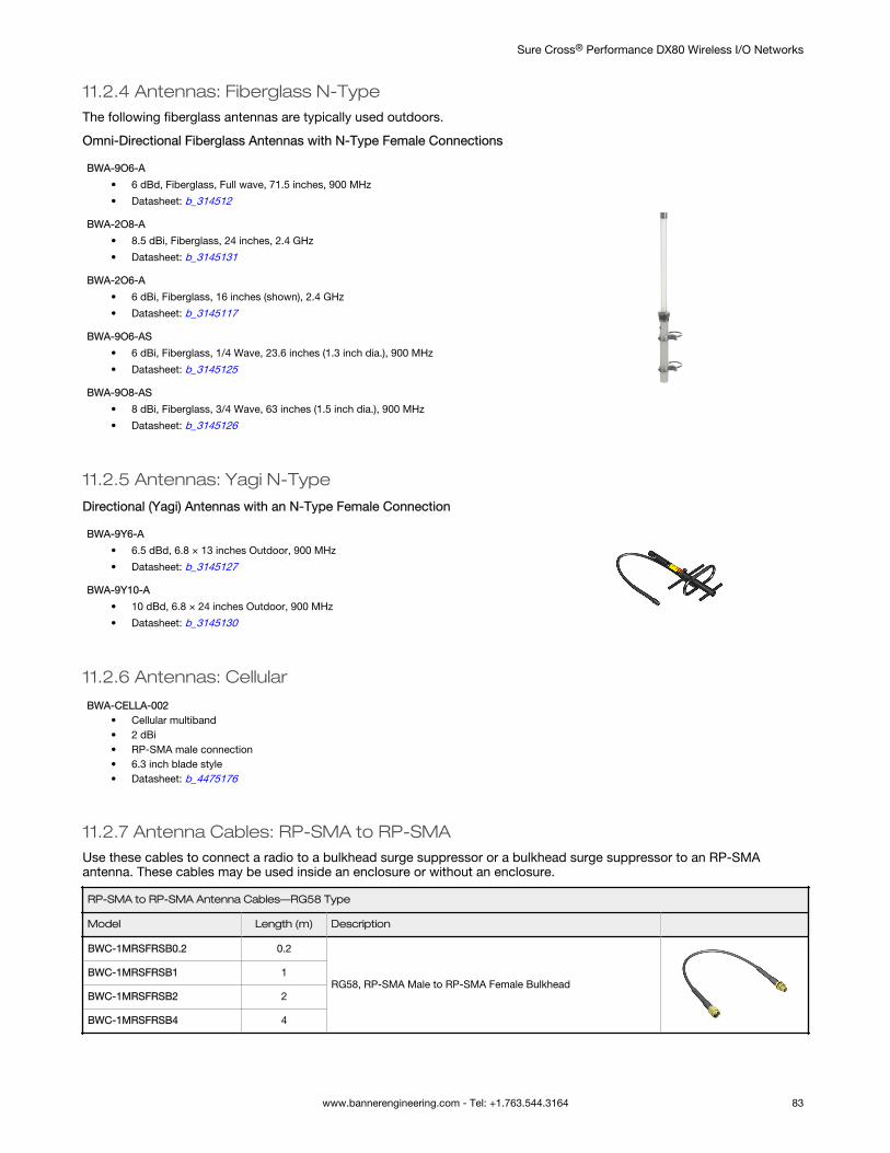
11.2.4 Antennas: Fiberglass N-TypeThe following fiberglass antennas are typically used outdoors.
Omni-Directional Fiberglass Antennas with N-Type Female Connections
BWA-9O6-A
• 6 dBd, Fiberglass, Full wave, 71.5 inches, 900 MHz
• Datasheet: b_314512
BWA-2O8-A
• 8.5 dBi, Fiberglass, 24 inches, 2.4 GHz
• Datasheet: b_3145131
BWA-2O6-A
• 6 dBi, Fiberglass, 16 inches (shown), 2.4 GHz
• Datasheet: b_3145117
BWA-9O6-AS
• 6 dBi, Fiberglass, 1/4 Wave, 23.6 inches (1.3 inch dia.), 900 MHz
• Datasheet: b_3145125
BWA-9O8-AS
• 8 dBi, Fiberglass, 3/4 Wave, 63 inches (1.5 inch dia.), 900 MHz
• Datasheet: b_3145126
11.2.5 Antennas: Yagi N-Type
Directional (Yagi) Antennas with an N-Type Female Connection
BWA-9Y6-A
• 6.5 dBd, 6.8 × 13 inches Outdoor, 900 MHz
• Datasheet: b_3145127
BWA-9Y10-A
• 10 dBd, 6.8 × 24 inches Outdoor, 900 MHz
• Datasheet: b_3145130
11.2.6 Antennas: Cellular
BWA-CELLA-002• Cellular multiband• 2 dBi• RP-SMA male connection• 6.3 inch blade style• Datasheet: b_4475176
11.2.7 Antenna Cables: RP-SMA to RP-SMAUse these cables to connect a radio to a bulkhead surge suppressor or a bulkhead surge suppressor to an RP-SMAantenna. These cables may be used inside an enclosure or without an enclosure.
RP-SMA to RP-SMA Antenna Cables—RG58 Type
Model Length (m) Description
BWC-1MRSFRSB0.2 0.2
RG58, RP-SMA Male to RP-SMA Female BulkheadBWC-1MRSFRSB1 1
BWC-1MRSFRSB2 2
BWC-1MRSFRSB4 4
Sure Cross® Performance DX80 Wireless I/O Networks
www.bannerengineering.com - Tel: +1.763.544.3164 83
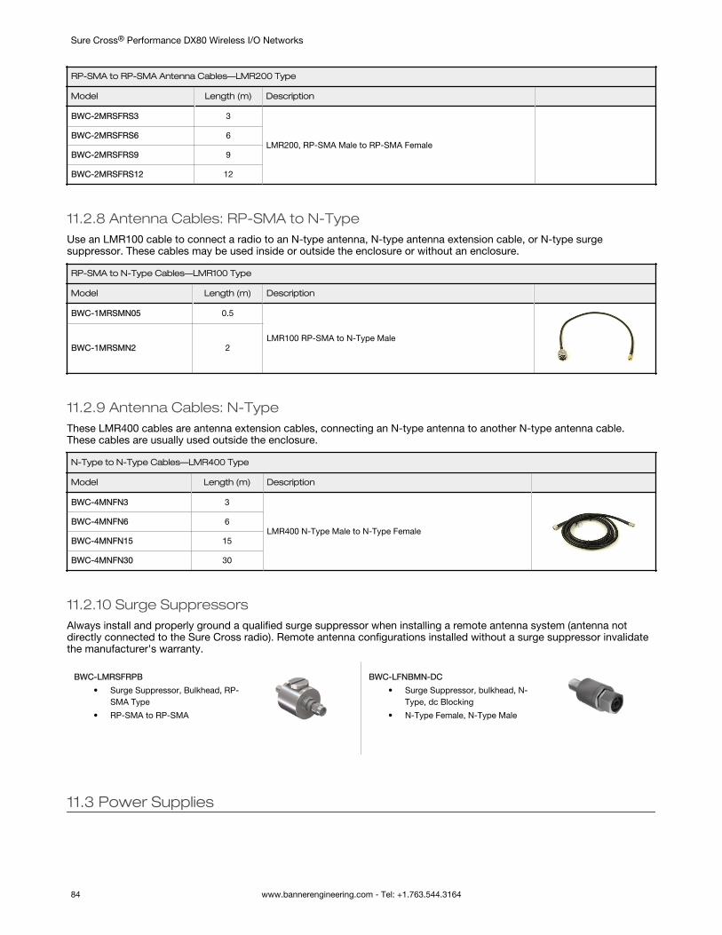
RP-SMA to RP-SMA Antenna Cables—LMR200 Type
Model Length (m) Description
BWC-2MRSFRS3 3
LMR200, RP-SMA Male to RP-SMA FemaleBWC-2MRSFRS6 6
BWC-2MRSFRS9 9
BWC-2MRSFRS12 12
11.2.8 Antenna Cables: RP-SMA to N-TypeUse an LMR100 cable to connect a radio to an N-type antenna, N-type antenna extension cable, or N-type surgesuppressor. These cables may be used inside or outside the enclosure or without an enclosure.
RP-SMA to N-Type Cables—LMR100 Type
Model Length (m) Description
BWC-1MRSMN05 0.5
LMR100 RP-SMA to N-Type MaleBWC-1MRSMN2 2
11.2.9 Antenna Cables: N-TypeThese LMR400 cables are antenna extension cables, connecting an N-type antenna to another N-type antenna cable.These cables are usually used outside the enclosure.
N-Type to N-Type Cables—LMR400 Type
Model Length (m) Description
BWC-4MNFN3 3
LMR400 N-Type Male to N-Type FemaleBWC-4MNFN6 6
BWC-4MNFN15 15
BWC-4MNFN30 30
11.2.10 Surge SuppressorsAlways install and properly ground a qualified surge suppressor when installing a remote antenna system (antenna notdirectly connected to the Sure Cross radio). Remote antenna configurations installed without a surge suppressor invalidatethe manufacturer's warranty.
BWC-LMRSFRPB
• Surge Suppressor, Bulkhead, RP-SMA Type
• RP-SMA to RP-SMA
BWC-LFNBMN-DC
• Surge Suppressor, bulkhead, N-Type, dc Blocking
• N-Type Female, N-Type Male
11.3 Power Supplies
Sure Cross® Performance DX80 Wireless I/O Networks
84 www.bannerengineering.com - Tel: +1.763.544.3164
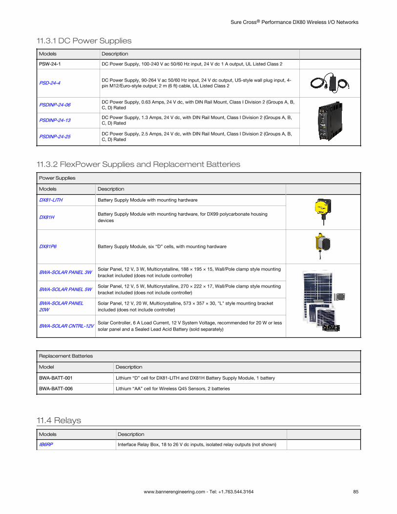
11.3.1 DC Power Supplies
Models Description
PSW-24-1 DC Power Supply, 100-240 V ac 50/60 Hz input, 24 V dc 1 A output, UL Listed Class 2
PSD-24-4 DC Power Supply, 90-264 V ac 50/60 Hz input, 24 V dc output, US-style wall plug input, 4-pin M12/Euro-style output; 2 m (6 ft) cable, UL Listed Class 2
PSDINP-24-06 DC Power Supply, 0.63 Amps, 24 V dc, with DIN Rail Mount, Class I Division 2 (Groups A, B,C, D) Rated
PSDINP-24-13 DC Power Supply, 1.3 Amps, 24 V dc, with DIN Rail Mount, Class I Division 2 (Groups A, B,C, D) Rated
PSDINP-24-25 DC Power Supply, 2.5 Amps, 24 V dc, with DIN Rail Mount, Class I Division 2 (Groups A, B,C, D) Rated
11.3.2 FlexPower Supplies and Replacement Batteries
Power Supplies
Models Description
DX81-LITH Battery Supply Module with mounting hardware
DX81HBattery Supply Module with mounting hardware, for DX99 polycarbonate housingdevices
DX81P6 Battery Supply Module, six “D” cells, with mounting hardware
BWA-SOLAR PANEL 3WSolar Panel, 12 V, 3 W, Multicrystalline, 188 × 195 × 15, Wall/Pole clamp style mountingbracket included (does not include controller)
BWA-SOLAR PANEL 5WSolar Panel, 12 V, 5 W, Multicrystalline, 270 × 222 × 17, Wall/Pole clamp style mountingbracket included (does not include controller)
BWA-SOLAR PANEL20W
Solar Panel, 12 V, 20 W, Multicrystalline, 573 × 357 × 30, "L" style mounting bracketincluded (does not include controller)
BWA-SOLAR CNTRL-12VSolar Controller, 6 A Load Current, 12 V System Voltage, recommended for 20 W or lesssolar panel and a Sealed Lead Acid Battery (sold separately)
Replacement Batteries
Model Description
BWA-BATT-001 Lithium “D” cell for DX81-LITH and DX81H Battery Supply Module, 1 battery
BWA-BATT-006 Lithium “AA” cell for Wireless Q45 Sensors, 2 batteries
11.4 Relays
Models Description
IB6RP Interface Relay Box, 18 to 26 V dc inputs, isolated relay outputs (not shown)
Sure Cross® Performance DX80 Wireless I/O Networks
www.bannerengineering.com - Tel: +1.763.544.3164 85

Models Description
BWA-RELAY-12V Relay, Blade Style with Base, 12 V
BWA-RELAY-24V Relay, Blade Style with Base, 24 V
BWA-RH1B-UDC12V Relay, Blade Style, No Base, 12 V (replacement part)
BWA-RH1B-UDC24V Relay, Blade Style, No Base, 24 V (replacement part)
BWA-SH1B-05 Relay Base Only (replacement part)
11.5 Sensors
11.5.1 Sensors with a Serial InterfaceThe following sensors are designed to be used with any of the 1-Wire Serial Interface Nodes.
K50UX1RA
• U-GAGE Ultrasonic Sensor with1-wire serial interface
• Datasheet: 191599
M12FTH4Q
• Temperature and HumiditySensor, ±2% Accuracy, 1-wireserial interface
• (Requires a 5-pin threaded M12/Euro-style double-ended cordsetless than 3 meters long, such asmodel DEE2R-5xD.)
• Datasheet: 162669
M12FT4Q
• Temperature Sensor with 1-wireserial interface
• (Requires a 5-pin threaded M12/Euro-style double-ended cordsetless than 3 meters long, such asmodel DEE2R-5xD.)
• Datasheet: 162669
Sure Cross® Performance DX80 Wireless I/O Networks
86 www.bannerengineering.com - Tel: +1.763.544.3164
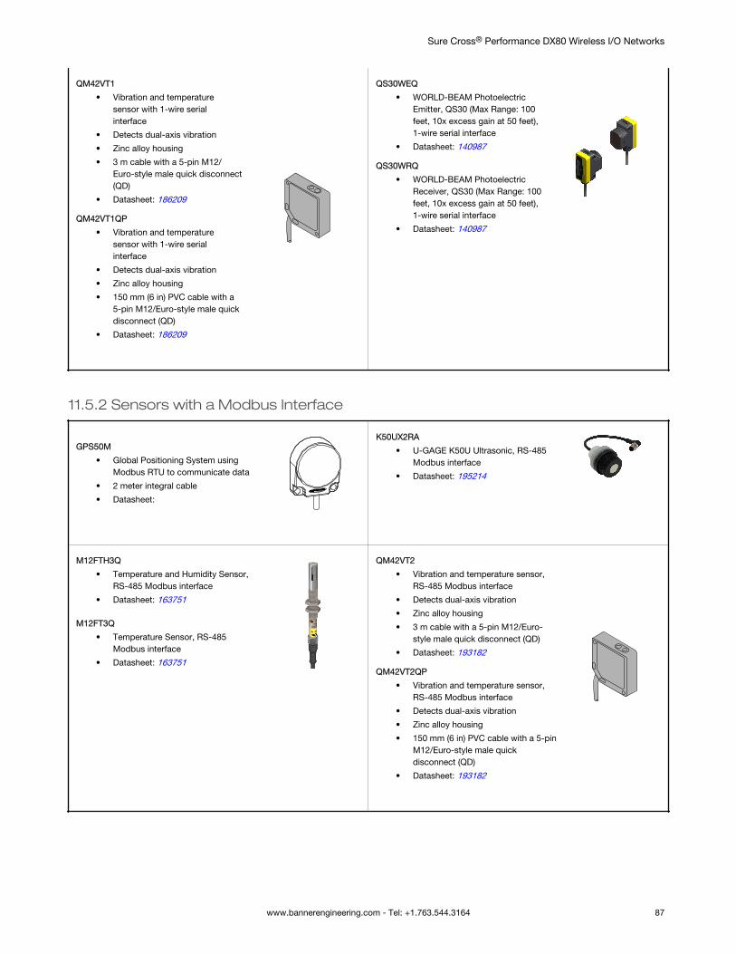
QM42VT1
• Vibration and temperaturesensor with 1-wire serialinterface
• Detects dual-axis vibration
• Zinc alloy housing
• 3 m cable with a 5-pin M12/Euro-style male quick disconnect(QD)
• Datasheet: 186209
QM42VT1QP
• Vibration and temperaturesensor with 1-wire serialinterface
• Detects dual-axis vibration
• Zinc alloy housing
• 150 mm (6 in) PVC cable with a5-pin M12/Euro-style male quickdisconnect (QD)
• Datasheet: 186209
QS30WEQ
• WORLD-BEAM PhotoelectricEmitter, QS30 (Max Range: 100feet, 10x excess gain at 50 feet),1-wire serial interface
• Datasheet: 140987
QS30WRQ
• WORLD-BEAM PhotoelectricReceiver, QS30 (Max Range: 100feet, 10x excess gain at 50 feet),1-wire serial interface
• Datasheet: 140987
11.5.2 Sensors with a Modbus Interface
GPS50M
• Global Positioning System usingModbus RTU to communicate data
• 2 meter integral cable
• Datasheet:
K50UX2RA
• U-GAGE K50U Ultrasonic, RS-485Modbus interface
• Datasheet: 195214
M12FTH3Q
• Temperature and Humidity Sensor,RS-485 Modbus interface
• Datasheet: 163751
M12FT3Q
• Temperature Sensor, RS-485Modbus interface
• Datasheet: 163751
QM42VT2
• Vibration and temperature sensor,RS-485 Modbus interface
• Detects dual-axis vibration
• Zinc alloy housing
• 3 m cable with a 5-pin M12/Euro-style male quick disconnect (QD)
• Datasheet: 193182
QM42VT2QP
• Vibration and temperature sensor,RS-485 Modbus interface
• Detects dual-axis vibration
• Zinc alloy housing
• 150 mm (6 in) PVC cable with a 5-pinM12/Euro-style male quickdisconnect (QD)
• Datasheet: 193182
Sure Cross® Performance DX80 Wireless I/O Networks
www.bannerengineering.com - Tel: +1.763.544.3164 87
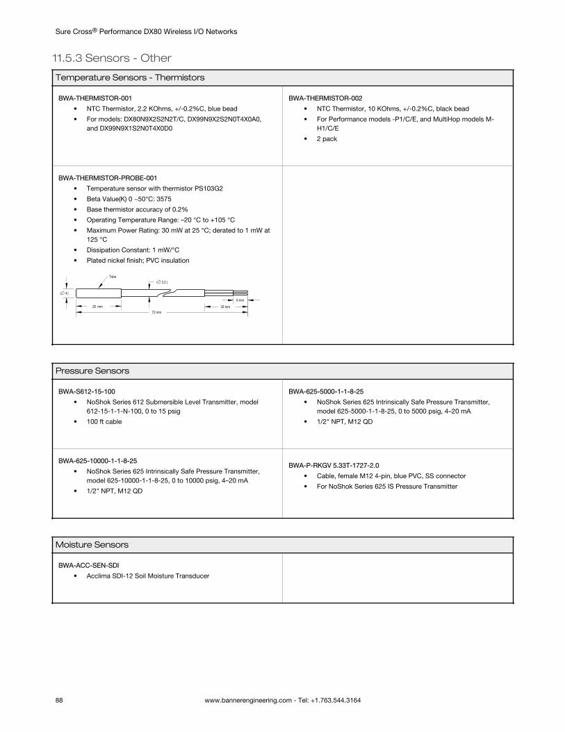
11.5.3 Sensors - Other
Temperature Sensors - Thermistors
BWA-THERMISTOR-001
• NTC Thermistor, 2.2 KOhms, +/-0.2%C, blue bead
• For models: DX80N9X2S2N2T/C, DX99N9X2S2N0T4X0A0,and DX99N9X1S2N0T4X0D0
BWA-THERMISTOR-002
• NTC Thermistor, 10 KOhms, +/-0.2%C, black bead
• For Performance models -P1/C/E, and MultiHop models M-H1/C/E
• 2 pack
BWA-THERMISTOR-PROBE-001
• Temperature sensor with thermistor PS103G2
• Beta Value(K) 0 ~50°C: 3575
• Base thermistor accuracy of 0.2%
• Operating Temperature Range: –20 °C to +105 °C
• Maximum Power Rating: 30 mW at 25 °C; derated to 1 mW at125 °C
• Dissipation Constant: 1 mW/°C
• Plated nickel finish; PVC insulation
( 3.2 )
35 mm
6 mm
( 4)
20 mm72 mm
Tube
Pressure Sensors
BWA-S612-15-100
• NoShok Series 612 Submersible Level Transmitter, model612-15-1-1-N-100, 0 to 15 psig
• 100 ft cable
BWA-625-5000-1-1-8-25
• NoShok Series 625 Intrinsically Safe Pressure Transmitter,model 625-5000-1-1-8-25, 0 to 5000 psig, 4–20 mA
• 1/2" NPT, M12 QD
BWA-625-10000-1-1-8-25
• NoShok Series 625 Intrinsically Safe Pressure Transmitter,model 625-10000-1-1-8-25, 0 to 10000 psig, 4–20 mA
• 1/2" NPT, M12 QD
BWA-P-RKGV 5.33T-1727-2.0
• Cable, female M12 4-pin, blue PVC, SS connector
• For NoShok Series 625 IS Pressure Transmitter
Moisture Sensors
BWA-ACC-SEN-SDI
• Acclima SDI-12 Soil Moisture Transducer
Sure Cross® Performance DX80 Wireless I/O Networks
88 www.bannerengineering.com - Tel: +1.763.544.3164
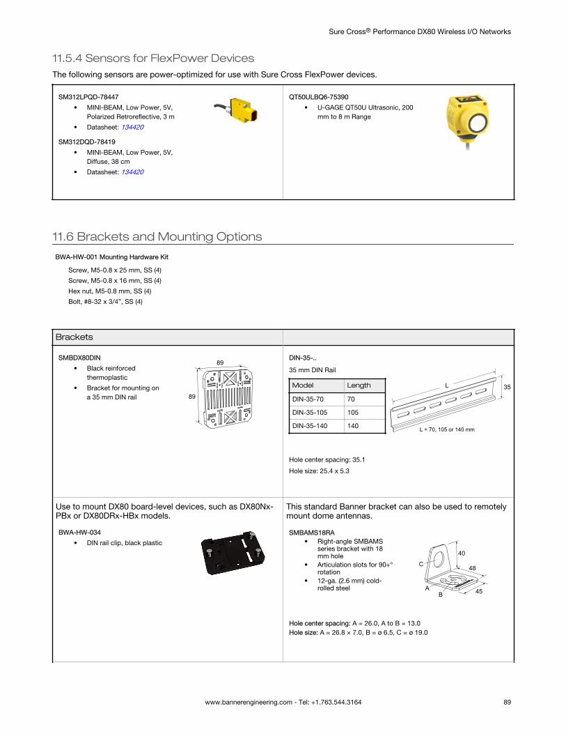
11.5.4 Sensors for FlexPower DevicesThe following sensors are power-optimized for use with Sure Cross FlexPower devices.
SM312LPQD-78447
• MINI-BEAM, Low Power, 5V,Polarized Retroreflective, 3 m
• Datasheet: 134420
SM312DQD-78419
• MINI-BEAM, Low Power, 5V,Diffuse, 38 cm
• Datasheet: 134420
QT50ULBQ6-75390
• U-GAGE QT50U Ultrasonic, 200mm to 8 m Range
11.6 Brackets and Mounting Options
BWA-HW-001 Mounting Hardware Kit
Screw, M5-0.8 x 25 mm, SS (4)
Screw, M5-0.8 x 16 mm, SS (4)
Hex nut, M5-0.8 mm, SS (4)
Bolt, #8-32 x 3/4”, SS (4)
Brackets
SMBDX80DIN
• Black reinforcedthermoplastic
• Bracket for mounting ona 35 mm DIN rail 89
89DIN-35-..
35 mm DIN Rail
Model Length
DIN-35-70 70
DIN-35-105 105
DIN-35-140 140 L = 70, 105 or 140 mm
L 35
Hole center spacing: 35.1
Hole size: 25.4 x 5.3
Use to mount DX80 board-level devices, such as DX80Nx-PBx or DX80DRx-HBx models.
BWA-HW-034
• DIN rail clip, black plastic
This standard Banner bracket can also be used to remotelymount dome antennas.
SMBAMS18RA• Right-angle SMBAMS
series bracket with 18mm hole
• Articulation slots for 90+°rotation
• 12-ga. (2.6 mm) cold-rolled steel
48
45
40
AB
C
Hole center spacing: A = 26.0, A to B = 13.0Hole size: A = 26.8 × 7.0, B = ø 6.5, C = ø 19.0
Sure Cross® Performance DX80 Wireless I/O Networks
www.bannerengineering.com - Tel: +1.763.544.3164 89
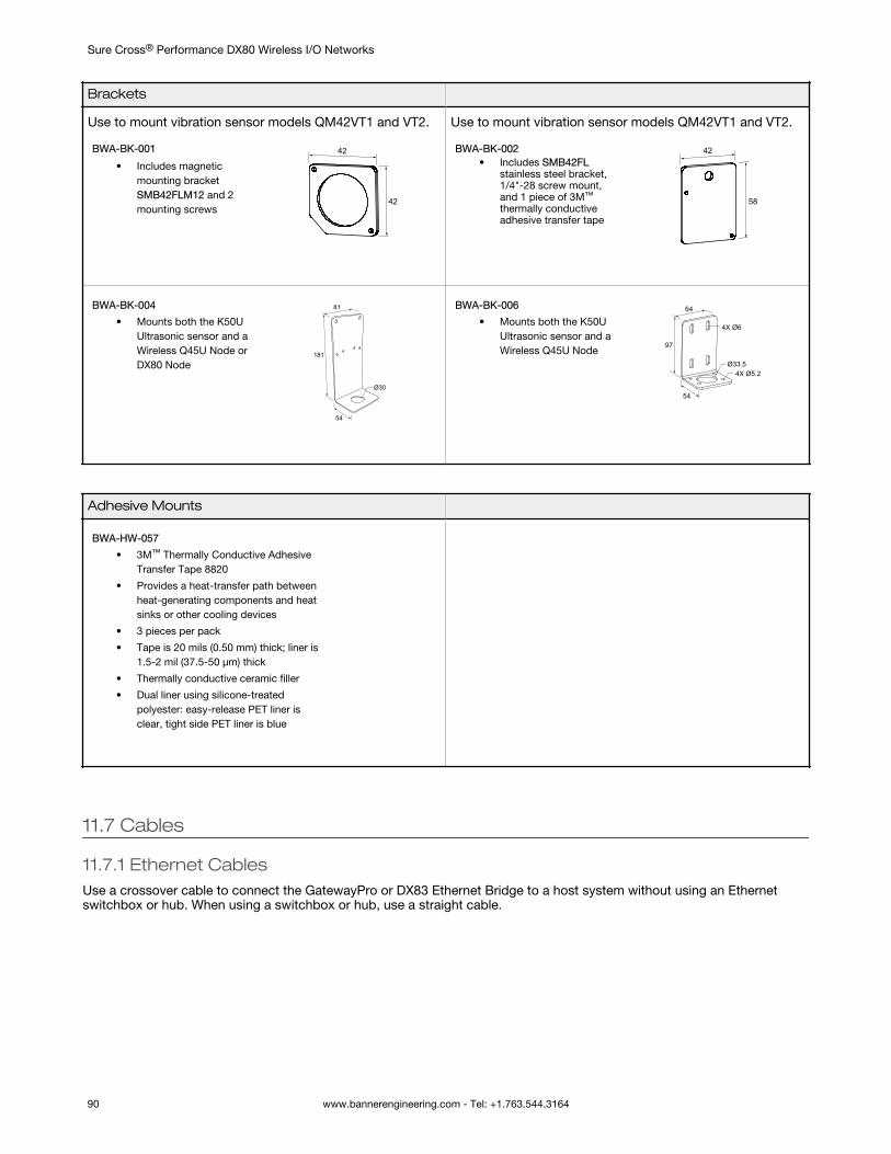
Brackets
Use to mount vibration sensor models QM42VT1 and VT2.
BWA-BK-001
• Includes magneticmounting bracketSMB42FLM12 and 2mounting screws
42
42
Use to mount vibration sensor models QM42VT1 and VT2.
BWA-BK-002• Includes SMB42FL
stainless steel bracket,1/4"-28 screw mount,and 1 piece of 3M™
thermally conductiveadhesive transfer tape
42
58
BWA-BK-004
• Mounts both the K50UUltrasonic sensor and aWireless Q45U Node orDX80 Node
81
54
181
Ø30
BWA-BK-006
• Mounts both the K50UUltrasonic sensor and aWireless Q45U Node
64
54
97
Ø33.54X Ø5.2
4X Ø6
Adhesive Mounts
BWA-HW-057
• 3M™ Thermally Conductive AdhesiveTransfer Tape 8820
• Provides a heat-transfer path betweenheat-generating components and heatsinks or other cooling devices
• 3 pieces per pack
• Tape is 20 mils (0.50 mm) thick; liner is1.5-2 mil (37.5-50 μm) thick
• Thermally conductive ceramic filler
• Dual liner using silicone-treatedpolyester: easy-release PET liner isclear, tight side PET liner is blue
11.7 Cables
11.7.1 Ethernet CablesUse a crossover cable to connect the GatewayPro or DX83 Ethernet Bridge to a host system without using an Ethernetswitchbox or hub. When using a switchbox or hub, use a straight cable.
Sure Cross® Performance DX80 Wireless I/O Networks
90 www.bannerengineering.com - Tel: +1.763.544.3164
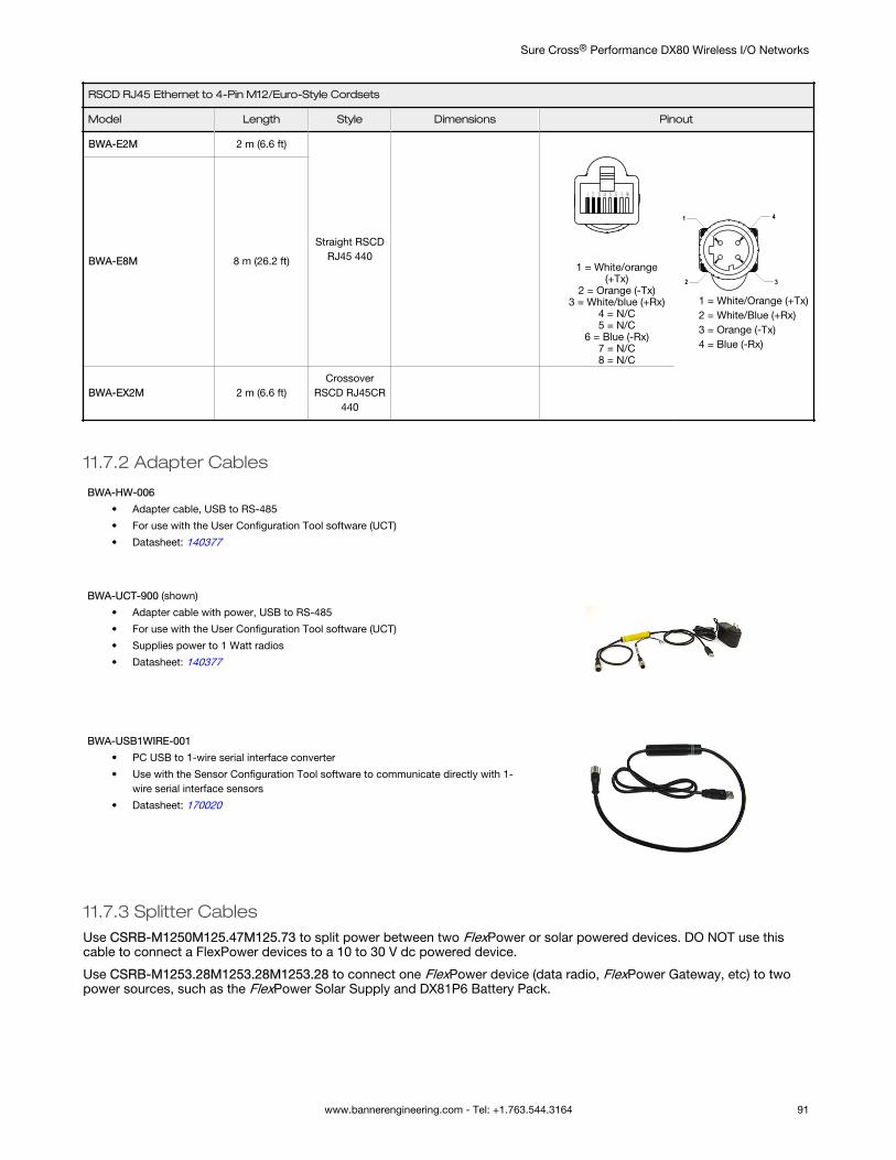
RSCD RJ45 Ethernet to 4-Pin M12/Euro-Style Cordsets
Model Length Style Dimensions Pinout
BWA-E2M 2 m (6.6 ft)
Straight RSCDRJ45 440
1 = White/orange(+Tx)
2 = Orange (-Tx)3 = White/blue (+Rx)
4 = N/C5 = N/C
6 = Blue (-Rx)7 = N/C8 = N/C
4
3
1
2
1 = White/Orange (+Tx)2 = White/Blue (+Rx)3 = Orange (-Tx)4 = Blue (-Rx)
BWA-E8M 8 m (26.2 ft)
BWA-EX2M 2 m (6.6 ft)Crossover
RSCD RJ45CR440
11.7.2 Adapter Cables
BWA-HW-006
• Adapter cable, USB to RS-485
• For use with the User Configuration Tool software (UCT)
• Datasheet: 140377
BWA-UCT-900 (shown)
• Adapter cable with power, USB to RS-485
• For use with the User Configuration Tool software (UCT)
• Supplies power to 1 Watt radios
• Datasheet: 140377
BWA-USB1WIRE-001
• PC USB to 1-wire serial interface converter
• Use with the Sensor Configuration Tool software to communicate directly with 1-wire serial interface sensors
• Datasheet: 170020
11.7.3 Splitter CablesUse CSRB-M1250M125.47M125.73 to split power between two FlexPower or solar powered devices. DO NOT use thiscable to connect a FlexPower devices to a 10 to 30 V dc powered device.
Use CSRB-M1253.28M1253.28M1253.28 to connect one FlexPower device (data radio, FlexPower Gateway, etc) to twopower sources, such as the FlexPower Solar Supply and DX81P6 Battery Pack.
Sure Cross® Performance DX80 Wireless I/O Networks
www.bannerengineering.com - Tel: +1.763.544.3164 91
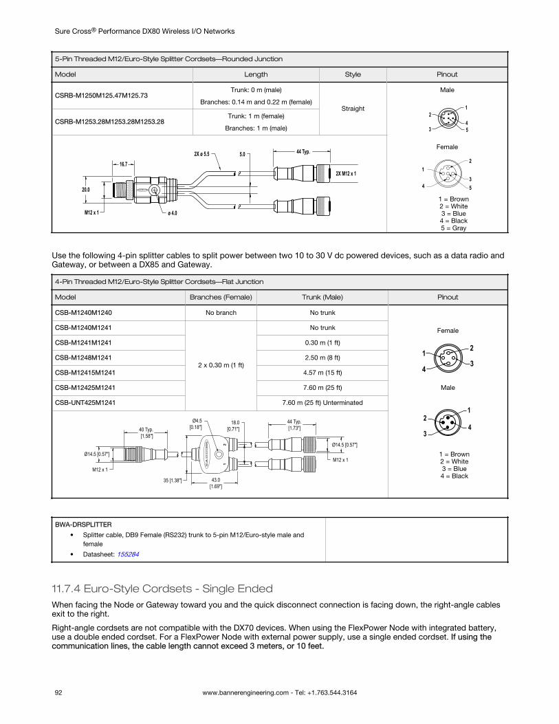
5-Pin Threaded M12/Euro-Style Splitter Cordsets—Rounded Junction
Model Length Style Pinout
CSRB-M1250M125.47M125.73Trunk: 0 m (male)
Branches: 0.14 m and 0.22 m (female)Straight
Male
1
453
2
Female
2
34
1
5
1 = Brown2 = White3 = Blue4 = Black5 = Gray
CSRB-M1253.28M1253.28M1253.28Trunk: 1 m (female)
Branches: 1 m (male)
44 Typ.
2X M12 x 1
20.0
5.02X ø 5.5
ø 4.0M12 x 1
16.7
Use the following 4-pin splitter cables to split power between two 10 to 30 V dc powered devices, such as a data radio andGateway, or between a DX85 and Gateway.
4-Pin Threaded M12/Euro-Style Splitter Cordsets—Flat Junction
Model Branches (Female) Trunk (Male) Pinout
CSB-M1240M1240 No branch No trunk
Female
2
34
1
Male
1
43
2
1 = Brown2 = White3 = Blue4 = Black
CSB-M1240M1241
2 x 0.30 m (1 ft)
No trunk
CSB-M1241M1241 0.30 m (1 ft)
CSB-M1248M1241 2.50 m (8 ft)
CSB-M12415M1241 4.57 m (15 ft)
CSB-M12425M1241 7.60 m (25 ft)
CSB-UNT425M1241 7.60 m (25 ft) Unterminated
44 Typ.[1.73"]
43.0[1.69"]
Ø14.5 [0.57"]
M12 x 1Ø14.5 [0.57"]
40 Typ. [1.58"]
18.0[0.71"]
Ø4.5[0.18"]
35 [1.38"]
M12 x 1
BWA-DRSPLITTER
• Splitter cable, DB9 Female (RS232) trunk to 5-pin M12/Euro-style male andfemale
• Datasheet: 155284
11.7.4 Euro-Style Cordsets - Single EndedWhen facing the Node or Gateway toward you and the quick disconnect connection is facing down, the right-angle cablesexit to the right.
Right-angle cordsets are not compatible with the DX70 devices. When using the FlexPower Node with integrated battery,use a double ended cordset. For a FlexPower Node with external power supply, use a single ended cordset. If using thecommunication lines, the cable length cannot exceed 3 meters, or 10 feet.
Sure Cross® Performance DX80 Wireless I/O Networks
92 www.bannerengineering.com - Tel: +1.763.544.3164
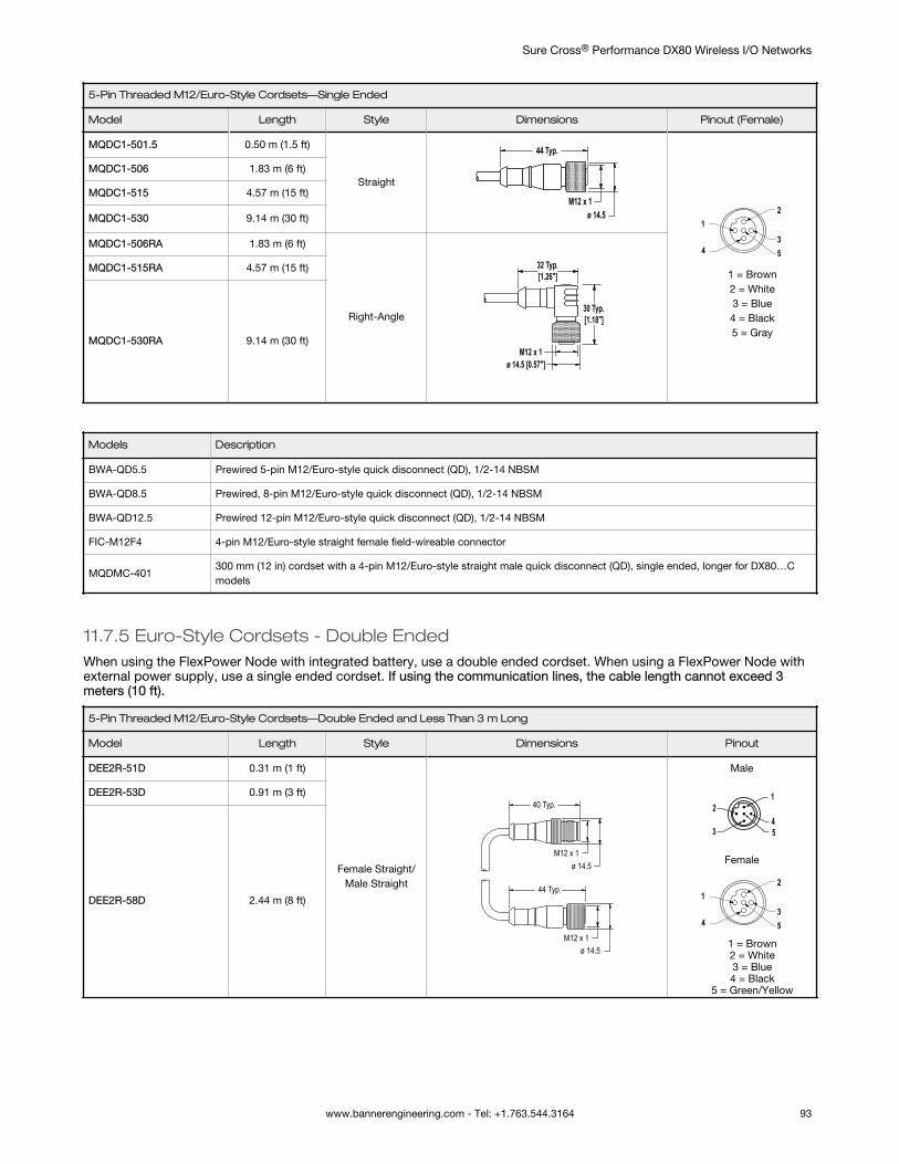
5-Pin Threaded M12/Euro-Style Cordsets—Single Ended
Model Length Style Dimensions Pinout (Female)
MQDC1-501.5 0.50 m (1.5 ft)
Straight
44 Typ.
ø 14.5M12 x 1
2
34
1
5
1 = Brown2 = White3 = Blue4 = Black5 = Gray
MQDC1-506 1.83 m (6 ft)
MQDC1-515 4.57 m (15 ft)
MQDC1-530 9.14 m (30 ft)
MQDC1-506RA 1.83 m (6 ft)
Right-Angle
32 Typ.[1.26"]
30 Typ.[1.18"]
ø 14.5 [0.57"]M12 x 1
MQDC1-515RA 4.57 m (15 ft)
MQDC1-530RA 9.14 m (30 ft)
Models Description
BWA-QD5.5 Prewired 5-pin M12/Euro-style quick disconnect (QD), 1/2-14 NBSM
BWA-QD8.5 Prewired, 8-pin M12/Euro-style quick disconnect (QD), 1/2-14 NBSM
BWA-QD12.5 Prewired 12-pin M12/Euro-style quick disconnect (QD), 1/2-14 NBSM
FIC-M12F4 4-pin M12/Euro-style straight female field-wireable connector
MQDMC-401300 mm (12 in) cordset with a 4-pin M12/Euro-style straight male quick disconnect (QD), single ended, longer for DX80…Cmodels
11.7.5 Euro-Style Cordsets - Double EndedWhen using the FlexPower Node with integrated battery, use a double ended cordset. When using a FlexPower Node withexternal power supply, use a single ended cordset. If using the communication lines, the cable length cannot exceed 3meters (10 ft).
5-Pin Threaded M12/Euro-Style Cordsets—Double Ended and Less Than 3 m Long
Model Length Style Dimensions Pinout
DEE2R-51D 0.31 m (1 ft)
Female Straight/Male Straight
40 Typ.
ø 14.5M12 x 1
44 Typ.
ø 14.5M12 x 1
Male
1
453
2
Female
2
34
1
5
1 = Brown2 = White3 = Blue4 = Black
5 = Green/Yellow
DEE2R-53D 0.91 m (3 ft)
DEE2R-58D 2.44 m (8 ft)
Sure Cross® Performance DX80 Wireless I/O Networks
www.bannerengineering.com - Tel: +1.763.544.3164 93
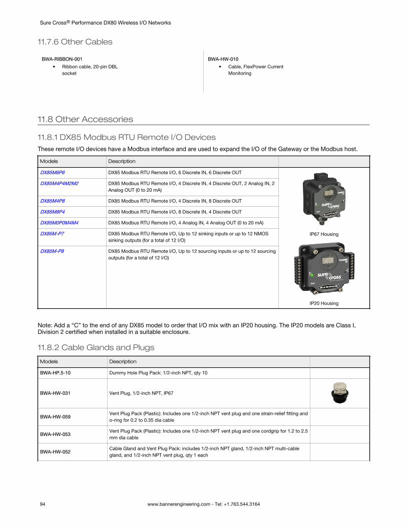
11.7.6 Other Cables
BWA-RIBBON-001
• Ribbon cable, 20-pin DBLsocket
BWA-HW-010
• Cable, FlexPower CurrentMonitoring
11.8 Other Accessories
11.8.1 DX85 Modbus RTU Remote I/O DevicesThese remote I/O devices have a Modbus interface and are used to expand the I/O of the Gateway or the Modbus host.
Models Description
DX85M6P6 DX85 Modbus RTU Remote I/O, 6 Discrete IN, 6 Discrete OUT
IP67 Housing
IP20 Housing
DX85M4P4M2M2 DX85 Modbus RTU Remote I/O, 4 Discrete IN, 4 Discrete OUT, 2 Analog IN, 2Analog OUT (0 to 20 mA)
DX85M4P8 DX85 Modbus RTU Remote I/O, 4 Discrete IN, 8 Discrete OUT
DX85M8P4 DX85 Modbus RTU Remote I/O, 8 Discrete IN, 4 Discrete OUT
DX85M0P0M4M4 DX85 Modbus RTU Remote I/O, 4 Analog IN, 4 Analog OUT (0 to 20 mA)
DX85M-P7 DX85 Modbus RTU Remote I/O, Up to 12 sinking inputs or up to 12 NMOSsinking outputs (for a total of 12 I/O)
DX85M-P8 DX85 Modbus RTU Remote I/O, Up to 12 sourcing inputs or up to 12 sourcingoutputs (for a total of 12 I/O)
Note: Add a “C” to the end of any DX85 model to order that I/O mix with an IP20 housing. The IP20 models are Class I,Division 2 certified when installed in a suitable enclosure.
11.8.2 Cable Glands and Plugs
Models Description
BWA-HP.5-10 Dummy Hole Plug Pack: 1/2-inch NPT, qty 10
BWA-HW-031 Vent Plug, 1/2-inch NPT, IP67
BWA-HW-059Vent Plug Pack (Plastic): Includes one 1/2-inch NPT vent plug and one strain-relief fitting ando-ring for 0.2 to 0.35 dia cable
BWA-HW-053Vent Plug Pack (Plastic): Includes one 1/2-inch NPT vent plug and one cordgrip for 1.2 to 2.5mm dia cable
BWA-HW-052Cable Gland and Vent Plug Pack: includes 1/2-inch NPT gland, 1/2-inch NPT multi-cablegland, and 1/2-inch NPT vent plug, qty 1 each
Sure Cross® Performance DX80 Wireless I/O Networks
94 www.bannerengineering.com - Tel: +1.763.544.3164
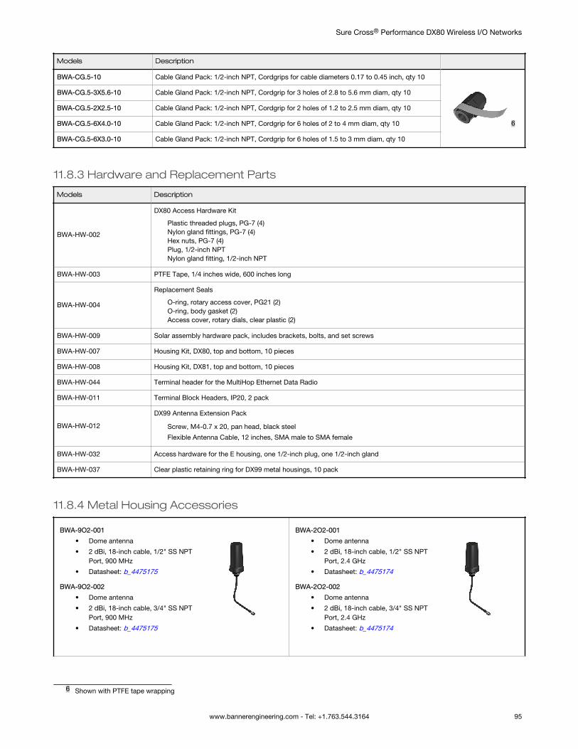
Models Description
BWA-CG.5-10 Cable Gland Pack: 1/2-inch NPT, Cordgrips for cable diameters 0.17 to 0.45 inch, qty 10
6
BWA-CG.5-3X5.6-10 Cable Gland Pack: 1/2-inch NPT, Cordgrip for 3 holes of 2.8 to 5.6 mm diam, qty 10
BWA-CG.5-2X2.5-10 Cable Gland Pack: 1/2-inch NPT, Cordgrip for 2 holes of 1.2 to 2.5 mm diam, qty 10
BWA-CG.5-6X4.0-10 Cable Gland Pack: 1/2-inch NPT, Cordgrip for 6 holes of 2 to 4 mm diam, qty 10
BWA-CG.5-6X3.0-10 Cable Gland Pack: 1/2-inch NPT, Cordgrip for 6 holes of 1.5 to 3 mm diam, qty 10
11.8.3 Hardware and Replacement Parts
Models Description
BWA-HW-002
DX80 Access Hardware Kit
Plastic threaded plugs, PG-7 (4)Nylon gland fittings, PG-7 (4)Hex nuts, PG-7 (4)Plug, 1/2-inch NPTNylon gland fitting, 1/2-inch NPT
BWA-HW-003 PTFE Tape, 1/4 inches wide, 600 inches long
BWA-HW-004
Replacement Seals
O-ring, rotary access cover, PG21 (2)O-ring, body gasket (2)Access cover, rotary dials, clear plastic (2)
BWA-HW-009 Solar assembly hardware pack, includes brackets, bolts, and set screws
BWA-HW-007 Housing Kit, DX80, top and bottom, 10 pieces
BWA-HW-008 Housing Kit, DX81, top and bottom, 10 pieces
BWA-HW-044 Terminal header for the MultiHop Ethernet Data Radio
BWA-HW-011 Terminal Block Headers, IP20, 2 pack
BWA-HW-012
DX99 Antenna Extension Pack
Screw, M4-0.7 x 20, pan head, black steel
Flexible Antenna Cable, 12 inches, SMA male to SMA female
BWA-HW-032 Access hardware for the E housing, one 1/2-inch plug, one 1/2-inch gland
BWA-HW-037 Clear plastic retaining ring for DX99 metal housings, 10 pack
11.8.4 Metal Housing Accessories
BWA-9O2-001
• Dome antenna
• 2 dBi, 18-inch cable, 1/2" SS NPTPort, 900 MHz
• Datasheet: b_4475175
BWA-9O2-002
• Dome antenna
• 2 dBi, 18-inch cable, 3/4" SS NPTPort, 900 MHz
• Datasheet: b_4475175
BWA-2O2-001
• Dome antenna
• 2 dBi, 18-inch cable, 1/2" SS NPTPort, 2.4 GHz
• Datasheet: b_4475174
BWA-2O2-002
• Dome antenna
• 2 dBi, 18-inch cable, 3/4" SS NPTPort, 2.4 GHz
• Datasheet: b_4475174
6 Shown with PTFE tape wrapping
Sure Cross® Performance DX80 Wireless I/O Networks
www.bannerengineering.com - Tel: +1.763.544.3164 95
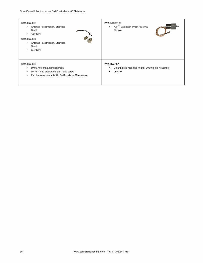
BWA-HW-016
• Antenna Feedthrough, StainlessSteel
• 1/2" NPT
BWA-HW-017
• Antenna Feedthrough, StainlessSteel
• 3/4" NPT
BWA-AXFS0130
• AXF™ Explosion-Proof AntennaCoupler
BWA-HW-012
• DX99 Antenna Extension Pack
• M4-0.7 × 20 black steel pan head screw
• Flexible antenna cable 12" SMA male to SMA female
BWA-HW-037
• Clear plastic retaining ring for DX99 metal housings
• Qty: 10
Sure Cross® Performance DX80 Wireless I/O Networks
96 www.bannerengineering.com - Tel: +1.763.544.3164
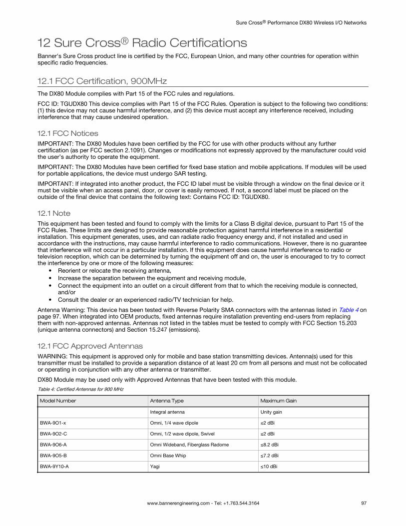
12 Sure Cross® Radio CertificationsBanner's Sure Cross product line is certified by the FCC, European Union, and many other countries for operation withinspecific radio frequencies.
12.1 FCC Certification, 900MHzThe DX80 Module complies with Part 15 of the FCC rules and regulations.
FCC ID: TGUDX80 This device complies with Part 15 of the FCC Rules. Operation is subject to the following two conditions:(1) this device may not cause harmful interference, and (2) this device must accept any interference received, includinginterference that may cause undesired operation.
12.1 FCC NoticesIMPORTANT: The DX80 Modules have been certified by the FCC for use with other products without any furthercertification (as per FCC section 2.1091). Changes or modifications not expressly approved by the manufacturer could voidthe user’s authority to operate the equipment.
IMPORTANT: The DX80 Modules have been certified for fixed base station and mobile applications. If modules will be usedfor portable applications, the device must undergo SAR testing.
IMPORTANT: If integrated into another product, the FCC ID label must be visible through a window on the final device or itmust be visible when an access panel, door, or cover is easily removed. If not, a second label must be placed on theoutside of the final device that contains the following text: Contains FCC ID: TGUDX80.
12.1 NoteThis equipment has been tested and found to comply with the limits for a Class B digital device, pursuant to Part 15 of theFCC Rules. These limits are designed to provide reasonable protection against harmful interference in a residentialinstallation. This equipment generates, uses, and can radiate radio frequency energy and, if not installed and used inaccordance with the instructions, may cause harmful interference to radio communications. However, there is no guaranteethat interference will not occur in a particular installation. If this equipment does cause harmful interference to radio ortelevision reception, which can be determined by turning the equipment off and on, the user is encouraged to try to correctthe interference by one or more of the following measures:
• Reorient or relocate the receiving antenna,• Increase the separation between the equipment and receiving module,• Connect the equipment into an outlet on a circuit different from that to which the receiving module is connected,
and/or• Consult the dealer or an experienced radio/TV technician for help.
Antenna Warning: This device has been tested with Reverse Polarity SMA connectors with the antennas listed in Table 4 onpage 97. When integrated into OEM products, fixed antennas require installation preventing end-users from replacingthem with non-approved antennas. Antennas not listed in the tables must be tested to comply with FCC Section 15.203(unique antenna connectors) and Section 15.247 (emissions).
12.1 FCC Approved AntennasWARNING: This equipment is approved only for mobile and base station transmitting devices. Antenna(s) used for thistransmitter must be installed to provide a separation distance of at least 20 cm from all persons and must not be collocatedor operating in conjunction with any other antenna or transmitter.
DX80 Module may be used only with Approved Antennas that have been tested with this module.
Table 4: Certified Antennas for 900 MHz
Model Number Antenna Type Maximum Gain
Integral antenna Unity gain
BWA-9O1-x Omni, 1/4 wave dipole ≤2 dBi
BWA-9O2-C Omni, 1/2 wave dipole, Swivel ≤2 dBi
BWA-9O6-A Omni Wideband, Fiberglass Radome ≤8.2 dBi
BWA-9O5-B Omni Base Whip ≤7.2 dBi
BWA-9Y10-A Yagi ≤10 dBi
Sure Cross® Performance DX80 Wireless I/O Networks
www.bannerengineering.com - Tel: +1.763.544.3164 97
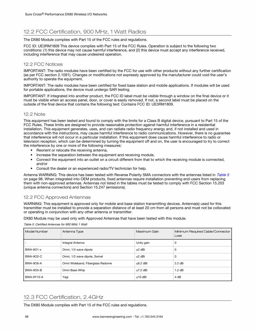
12.2 FCC Certification, 900 MHz, 1 Watt RadiosThe DX80 Module complies with Part 15 of the FCC rules and regulations.
FCC ID: UE3RM1809 This device complies with Part 15 of the FCC Rules. Operation is subject to the following twoconditions: (1) this device may not cause harmful interference, and (2) this device must accept any interference received,including interference that may cause undesired operation.
12.2 FCC NoticesIMPORTANT: The radio modules have been certified by the FCC for use with other products without any further certification(as per FCC section 2.1091). Changes or modifications not expressly approved by the manufacturer could void the user’sauthority to operate the equipment.
IMPORTANT: The radio modules have been certified for fixed base station and mobile applications. If modules will be usedfor portable applications, the device must undergo SAR testing.
IMPORTANT: If integrated into another product, the FCC ID label must be visible through a window on the final device or itmust be visible when an access panel, door, or cover is easily removed. If not, a second label must be placed on theoutside of the final device that contains the following text: Contains FCC ID: UE3RM1809.
12.2 NoteThis equipment has been tested and found to comply with the limits for a Class B digital device, pursuant to Part 15 of theFCC Rules. These limits are designed to provide reasonable protection against harmful interference in a residentialinstallation. This equipment generates, uses, and can radiate radio frequency energy and, if not installed and used inaccordance with the instructions, may cause harmful interference to radio communications. However, there is no guaranteethat interference will not occur in a particular installation. If this equipment does cause harmful interference to radio ortelevision reception, which can be determined by turning the equipment off and on, the user is encouraged to try to correctthe interference by one or more of the following measures:
• Reorient or relocate the receiving antenna,• Increase the separation between the equipment and receiving module,• Connect the equipment into an outlet on a circuit different from that to which the receiving module is connected,
and/or• Consult the dealer or an experienced radio/TV technician for help.
Antenna WARNING: This device has been tested with Reverse Polarity SMA connectors with the antennas listed in Table 5on page 98. When integrated into OEM products, fixed antennas require installation preventing end-users from replacingthem with non-approved antennas. Antennas not listed in the tables must be tested to comply with FCC Section 15.203(unique antenna connectors) and Section 15.247 (emissions).
12.2 FCC Approved AntennasWARNING: This equipment is approved only for mobile and base station transmitting devices. Antenna(s) used for thistransmitter must be installed to provide a separation distance of at least 20 cm from all persons and must not be collocatedor operating in conjunction with any other antenna or transmitter.
DX80 Module may be used only with Approved Antennas that have been tested with this module.
Table 5: Certified Antennas for 900 MHz 1 Watt
Model Number Antenna Type Maximum Gain Minimum Required Cable/ConnectorLoss
- Integral Antenna Unity gain 0
BWA-9O1-x Omni, 1/4 wave dipole ≤2 dBi 0
BWA-9O2-C Omni, 1/2 wave dipole, Swivel ≤2 dBi 0
BWA-9O6-A Omni Wideband, Fiberglass Radome ≤8.2 dBi 2.2 dB
BWA-9O5-B Omni Base Whip ≤7.2 dBi 1.2 dB
BWA-9Y10-A Yagi ≤10 dBi 4 dB
12.3 FCC Certification, 2.4GHzThe DX80 Module complies with Part 15 of the FCC rules and regulations.
Sure Cross® Performance DX80 Wireless I/O Networks
98 www.bannerengineering.com - Tel: +1.763.544.3164
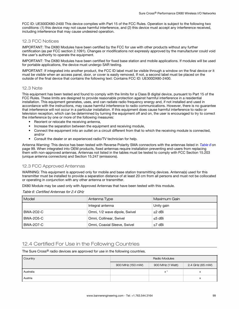
FCC ID: UE300DX80-2400 This device complies with Part 15 of the FCC Rules. Operation is subject to the following twoconditions: (1) this device may not cause harmful interference, and (2) this device must accept any interference received,including interference that may cause undesired operation.
12.3 FCC NoticesIMPORTANT: The DX80 Modules have been certified by the FCC for use with other products without any furthercertification (as per FCC section 2.1091). Changes or modifications not expressly approved by the manufacturer could voidthe user’s authority to operate the equipment.
IMPORTANT: The DX80 Modules have been certified for fixed base station and mobile applications. If modules will be usedfor portable applications, the device must undergo SAR testing.
IMPORTANT: If integrated into another product, the FCC ID label must be visible through a window on the final device or itmust be visible when an access panel, door, or cover is easily removed. If not, a second label must be placed on theoutside of the final device that contains the following text: Contains FCC ID: UE300DX80-2400.
12.3 NoteThis equipment has been tested and found to comply with the limits for a Class B digital device, pursuant to Part 15 of theFCC Rules. These limits are designed to provide reasonable protection against harmful interference in a residentialinstallation. This equipment generates, uses, and can radiate radio frequency energy and, if not installed and used inaccordance with the instructions, may cause harmful interference to radio communications. However, there is no guaranteethat interference will not occur in a particular installation. If this equipment does cause harmful interference to radio ortelevision reception, which can be determined by turning the equipment off and on, the user is encouraged to try to correctthe interference by one or more of the following measures:
• Reorient or relocate the receiving antenna,• Increase the separation between the equipment and receiving module,• Connect the equipment into an outlet on a circuit different from that to which the receiving module is connected,
and/or• Consult the dealer or an experienced radio/TV technician for help.
Antenna Warning: This device has been tested with Reverse Polarity SMA connectors with the antennas listed in Table 6 onpage 99. When integrated into OEM products, fixed antennas require installation preventing end-users from replacingthem with non-approved antennas. Antennas not listed in the tables must be tested to comply with FCC Section 15.203(unique antenna connectors) and Section 15.247 (emissions).
12.3 FCC Approved AntennasWARNING: This equipment is approved only for mobile and base station transmitting devices. Antenna(s) used for thistransmitter must be installed to provide a separation distance of at least 20 cm from all persons and must not be collocatedor operating in conjunction with any other antenna or transmitter.
DX80 Module may be used only with Approved Antennas that have been tested with this module.
Table 6: Certified Antennas for 2.4 GHz
Model Antenna Type Maximum Gain
Integral antenna Unity gain
BWA-2O2-C Omni, 1/2 wave dipole, Swivel ≤2 dBi
BWA-2O5-C Omni, Collinear, Swivel ≤5 dBi
BWA-2O7-C Omni, Coaxial Sleeve, Swivel ≤7 dBi
12.4 Certified For Use in the Following CountriesThe Sure Cross® radio devices are approved for use in the following countries.
Country Radio Modules
900 MHz (150 mW) 900 MHz (1 Watt) 2.4 GHz (65 mW)
Australia x * x
Austria x
Sure Cross® Performance DX80 Wireless I/O Networks
www.bannerengineering.com - Tel: +1.763.544.3164 99
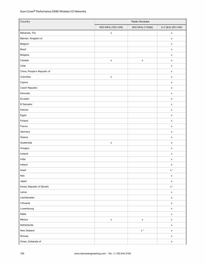
Country Radio Modules
900 MHz (150 mW) 900 MHz (1 Watt) 2.4 GHz (65 mW)
Bahamas, The x x
Bahrain, Kingdom of x
Belgium x
Brazil x
Bulgaria x
Canada x x x
Chile x
China, People's Republic of x
Colombia x x
Cyprus x
Czech Republic x
Denmark x
Ecuador x
El Salvador x
Estonia x
Egypt x
Finland x
France x
Germany x
Greece x
Guatemala x x
Hungary x
Iceland x
India x
Ireland x
Israel x *
Italy x
Japan x
Korea, Republic of (South) x *
Latvia x
Liechtenstein x
Lithuania x
Luxembourg x
Malta x
Mexico x x x
Netherlands x
New Zealand x * x
Norway x
Oman, Sultanate of x
Sure Cross® Performance DX80 Wireless I/O Networks
100 www.bannerengineering.com - Tel: +1.763.544.3164
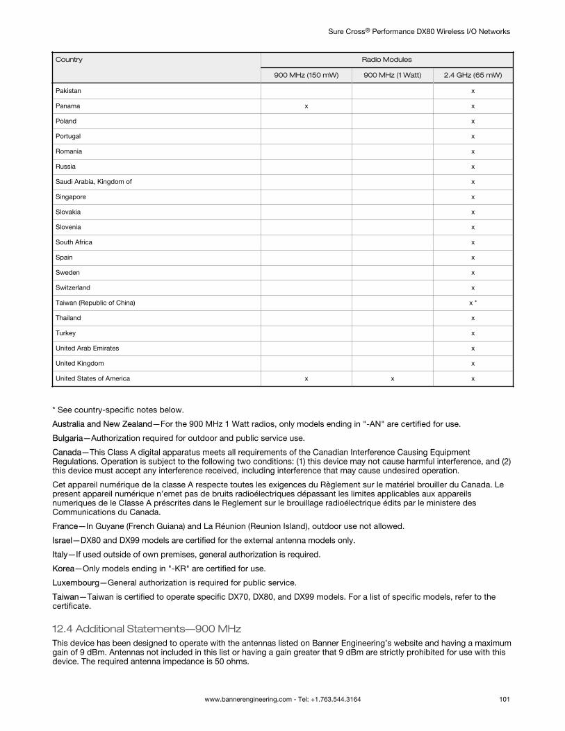
Country Radio Modules
900 MHz (150 mW) 900 MHz (1 Watt) 2.4 GHz (65 mW)
Pakistan x
Panama x x
Poland x
Portugal x
Romania x
Russia x
Saudi Arabia, Kingdom of x
Singapore x
Slovakia x
Slovenia x
South Africa x
Spain x
Sweden x
Switzerland x
Taiwan (Republic of China) x *
Thailand x
Turkey x
United Arab Emirates x
United Kingdom x
United States of America x x x
* See country-specific notes below.
Australia and New Zealand—For the 900 MHz 1 Watt radios, only models ending in "-AN" are certified for use.
Bulgaria—Authorization required for outdoor and public service use.
Canada—This Class A digital apparatus meets all requirements of the Canadian Interference Causing EquipmentRegulations. Operation is subject to the following two conditions: (1) this device may not cause harmful interference, and (2)this device must accept any interference received, including interference that may cause undesired operation.
Cet appareil numérique de la classe A respecte toutes les exigences du Règlement sur le matériel brouiller du Canada. Lepresent appareil numérique n’emet pas de bruits radioélectriques dépassant les limites applicables aux appareilsnumeriques de le Classe A préscrites dans le Reglement sur le brouillage radioélectrique édits par le ministere desCommunications du Canada.
France—In Guyane (French Guiana) and La Réunion (Reunion Island), outdoor use not allowed.
Israel—DX80 and DX99 models are certified for the external antenna models only.
Italy—If used outside of own premises, general authorization is required.
Korea—Only models ending in "-KR" are certified for use.
Luxembourg—General authorization is required for public service.
Taiwan—Taiwan is certified to operate specific DX70, DX80, and DX99 models. For a list of specific models, refer to thecertificate.
12.4 Additional Statements—900 MHzThis device has been designed to operate with the antennas listed on Banner Engineering’s website and having a maximumgain of 9 dBm. Antennas not included in this list or having a gain greater that 9 dBm are strictly prohibited for use with thisdevice. The required antenna impedance is 50 ohms.
Sure Cross® Performance DX80 Wireless I/O Networks
www.bannerengineering.com - Tel: +1.763.544.3164 101
To reduce potential radio interference to other users, the antenna type and its gain should be so chosen such that theequivalent isotropically radiated power (EIRP) is not more than that permitted for successful communication.
12.4 Transmit Power LevelsThe Sure Cross wireless products were certified for use in these countries using the standard antenna that ships with theproduct. When using other antennas, verify you are not exceeding the transmit power levels allowed by local governingagencies.
12.5 Exporting Sure Cross® RadiosExporting Sure Cross® Radios. It is our intent to fully comply with all national and regional regulations regarding radio frequency emissions. Customers who want to re-exportthis product to a country other than that to which it was sold must ensure the device is approved in the destination country. A list of approved countries appears in the RadioCertifications section of the product manual. The Sure Cross wireless products were certified for use in these countries using the antenna that ships with the product. Whenusing other antennas, verify you are not exceeding the transmit power levels allowed by local governing agencies. Consult with Banner Engineering Corp. if the destinationcountry is not on this list.
Sure Cross® Performance DX80 Wireless I/O Networks
102 www.bannerengineering.com - Tel: +1.763.544.3164
13 WarningsInstall and properly ground a qualified surge suppressor when installing a remote antenna system. Remote antenna configurations installed without surge suppressorsinvalidate the manufacturer's warranty. Keep the ground wire as short as possible and make all ground connections to a single-point ground system to ensure no ground loopsare created. No surge suppressor can absorb all lightning strikes; do not touch the Sure Cross® device or any equipment connected to the Sure Cross device during athunderstorm.
Exporting Sure Cross® Radios. It is our intent to fully comply with all national and regional regulations regarding radio frequency emissions. Customers who want to re-exportthis product to a country other than that to which it was sold must ensure the device is approved in the destination country. A list of approved countries appears in the RadioCertifications section of the product manual. The Sure Cross wireless products were certified for use in these countries using the antenna that ships with the product. Whenusing other antennas, verify you are not exceeding the transmit power levels allowed by local governing agencies. Consult with Banner Engineering Corp. if the destinationcountry is not on this list.
13.1 Banner Engineering Corp. Limited Warranty
Banner Engineering Corp. warrants its products to be free from defects in material and workmanship for one year following the date of shipment. Banner Engineering Corp. willrepair or replace, free of charge, any product of its manufacture which, at the time it is returned to the factory, is found to have been defective during the warranty period. Thiswarranty does not cover damage or liability for misuse, abuse, or the improper application or installation of the Banner product.
THIS LIMITED WARRANTY IS EXCLUSIVE AND IN LIEU OF ALL OTHER WARRANTIES WHETHER EXPRESS OR IMPLIED (INCLUDING, WITHOUT LIMITATION, ANYWARRANTY OF MERCHANTABILITY OR FITNESS FOR A PARTICULAR PURPOSE), AND WHETHER ARISING UNDER COURSE OF PERFORMANCE, COURSE OF DEALINGOR TRADE USAGE.
This Warranty is exclusive and limited to repair or, at the discretion of Banner Engineering Corp., replacement. IN NO EVENT SHALL BANNER ENGINEERING CORP. BELIABLE TO BUYER OR ANY OTHER PERSON OR ENTITY FOR ANY EXTRA COSTS, EXPENSES, LOSSES, LOSS OF PROFITS, OR ANY INCIDENTAL, CONSEQUENTIAL ORSPECIAL DAMAGES RESULTING FROM ANY PRODUCT DEFECT OR FROM THE USE OR INABILITY TO USE THE PRODUCT, WHETHER ARISING IN CONTRACT ORWARRANTY, STATUTE, TORT, STRICT LIABILITY, NEGLIGENCE, OR OTHERWISE.
Banner Engineering Corp. reserves the right to change, modify or improve the design of the product without assuming any obligations or liabilities relating to any productpreviously manufactured by Banner Engineering Corp. Any misuse, abuse, or improper application or installation of this product or use of the product for personal protectionapplications when the product is identified as not intended for such purposes will void the product warranty. Any modifications to this product without prior express approvalby Banner Engineering Corp will void the product warranties. All specifications published in this document are subject to change; Banner reserves the right to modify productspecifications or update documentation at any time. Specifications and product information in English supersede that which is provided in any other language. For the mostrecent version of any documentation, refer to: www.bannerengineering.com.
13.2 Contact Us
Corporate Headquarters
Address:Banner Engineering Corporate9714 Tenth Avenue NorthMinneapolis, Minnesota 55441, USA
Phone: +1 763 544 3164Website: www.bannerengineering.com
Europe
Address:Banner Engineering EMEAPark Lane, Culliganlaan 2F, bus 31831 Diegem, Belgium
Phone: +32 (0)2 456 0780Website: www.bannerengineering.comEmail: [email protected]
Turkey
Address:Banner Engineering Elk. San. Ve Tic. Ltd. Şti.Şerifali Mah. Münevver Sok. Ekomed Plaza No:10 Kat:4Ümraniye / İstanbul, Türkiye
Phone: +90 216 688 8282Website: www.bannerengineering.comEmail: [email protected]
India
Address:Banner Engineering India Pune Head QuartersOffice No. 1001, 10th Floor Sai Capital, Opp. ICC Senapati Bapat RoadPune 411016, India
Phone: +91 (0) 206 640 5624Website: www.bannerengineering.comEmail: [email protected]
Sure Cross® Performance DX80 Wireless I/O Networks
www.bannerengineering.com - Tel: +1.763.544.3164 103
Mexico
Address:Banner Engineering de Mexico Monterrey Head OfficeEdificio VAO Av. David Alfaro Siqueiros No.103 Col. Valle Oriente C.P.66269San Pedro Garza Garcia, Nuevo Leon, Mexico
Phone: +52 81 8363 2714 or 01 800 BANNERE (toll free)Website: www.bannerengineering.comEmail: [email protected]
Brazil
Address:Banner do BrasilRua Barão de Teffé nº 1000, sala 54Campos Elíseos, Jundiaí - SP, CEP.: 13208-761, Brasil
Phone: +55 11 2709 9880Website: www.bannerengineering.comEmail: [email protected]
China
Address:Banner Engineering Shanghai Rep OfficeXinlian Scientific Research Building Level 12, Building 21535 Hongmei Road, Shanghai 200233, China
Phone: +86 212 422 6888Website: www.bannerengineering.comEmail: [email protected]
Japan
Address:Banner Engineering JapanCent-Urban Building 305 3-23-15 Nishi-Nakajima Yodogawa-KuOsaka 532-0011, Japan
Phone: +81 (0)6 6309 0411Website: www.bannerengineering.comEmail: [email protected]
Taiwan
Address:Banner Engineering Taiwan8F-2, No. 308 Section 1, Neihu RoadTaipei 114, Taiwan
Phone: +886 (0)2 8751 9966Website: www.bannerengineering.comEmail: [email protected]
Sure Cross® Performance DX80 Wireless I/O Networks
104 www.bannerengineering.com - Tel: +1.763.544.3164
IndexA
antennaincrease height 24installing 25installing dome 27installing N-type 28installing remote 25–28weatherproofing 26
B
bad EE 77battery
integrated 66replacing 72, 73
baud rate 46binding 15, 41
C
chemical exposure 24collocation 25
E
ec XX 77enclosure 23error code
RF device time-out 7700 7701 7735 7736 77BAD EE 77EC 53 77EC 54 77EC xx 77FE 77Modbus time-out 77No LCD 77radio time-out 77
F
forming networks 15, 41fullscale 48
G
gasketmain body 72
ground 24ground wire 25–28
I
I/O isolation 25–28input value 48integrated battery 66
L
lightning arrestor 25–28link time-out 78
M
mechanical stress 24Modbus communication
parameters 45, 46Modbus time-out
error code 77
N
network ID 44no LCD 77null 48
O
offset 48outdoor installations 23overvoltage transients 24
P
parity 46
polling 78power
10 to 30V dc 65
R
radio link failure 78radio time-out 77, 78RF device time-out 77
S
seasonal changes 25setting slave ID 46slave ID 46span 48sunlight exposure 23surge suppressors 25–28system error 77
T
time-outradio 77, 78Modbus 77
U
unitsconversion 48
V
vibration 24
W
water exposure 23