supporting information hybrid lithium-sulfur …...s-1 supporting information hybrid lithium-sulfur...
TRANSCRIPT

S-1
Supporting Information
Hybrid Lithium-Sulfur Batteries with a Solid Electrolyte Membrane and Lithium
Polysulfide Catholyte
Xingwen Yu†, Zhonghe Bi
‡, Feng Zhao
‡*, and Arumugam Manthiram
†*
† Electrochemical Energy Laboratory, Materials Science and Engineering Program, The
University of Texas at Austin, Austin, TX 78712, USA
‡ Ceramatec, Inc., Salt Lake City, UT 84119, USA
*(A.M.) E-mail: [email protected].
*(F.Z.) E-mail: [email protected].

S-2
Table S1. Specifications and operating conditions for the hybrid Li-PS cells with the
LiSICON membrane
Criterion Cell specifications and operating conditions
Cell configuration
Area of the cathode
Cathode matrix
Catholyte
Separator
Capacity density
Capacity of the cell
Charge/discharge rate
CR 2032 coin cell
1.13 cm-2
Carbon nanofiber paper
0.67 M Li2S6 (4.0 M sulfur)
LiSICON membrane
2.85 mAh cm-2
3.2 mAh
C/10, C/5, C/3

S-3
Figure S1. (a) Schematic of a setup for polysulfide permeation experiments. (b) Photograph of
the sealed transparent tube with a piece of Celgard membrane embedded. (c) Photograph of the
sealed transparent tube with a piece of LiSICON membrane embedded.

S-4
Figure S2. Polysulfide diffusion tests of the (a and b) Celgard membrane and (c, d, and e)
LiSICON membrane after various resting times.

S-5
Figure S3. Electrochemical impedance spectroscopy (EIS) data of the three types of membrane-
electrode assemblies (MEAs) as illustrated in Figure 3a, b, and e in the paper. Black line: with
the application of a layer of liquid electrolyte at the Li-anode/LiSICON membrane interface;
blue line: with the application of a mechanical pressure to enhance the surface contact between
Li metal and the LiSICON membrane; pink line: with the insertion of a soft, facile Li-ion
transfer interlayer to accommodate the roughness at the Li anode/LiSICON membrane interface.

S-6
Figure S4. Typical charge/discharge profiles of a Li-S cell prepared with a traditional sulfur-
carbon cathode and a Celgard separator.
S-7
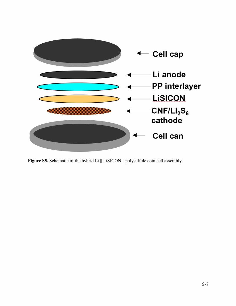
Figure S5. Schematic of the hybrid Li || LiSICON || polysulfide coin cell assembly.

S-8
Figure S6. Charge/discharge profiles of the hybrid Li || LiSICON || polysulfide batteries at
different representative cycles at (a) C/10, (b) C/5, and (c) C/3 rates.

S-9
Figure S7. (a) EIS spectra and (b) bulk resistance (RL) as a function of cycle number of the Li-S
cell with a LiSICON membrane solid electrolyte after various cycles at C/3 rate.