support for iua with sctp · americas headquarters: cisco systems, inc., 170 west tasman drive, san...
TRANSCRIPT

Americas Headquarters:Cisco Systems, Inc., 170 West Tasman Drive, San Jose, CA 95134-1706 USA
Support for IUA with SCTP
Document Release History
Feature History
This document describes the Support for ISDN Q.921 User Adaptation Layer (IUA) with Stream Controlled Transmission Protocol (SCTP) feature. This feature is described in the following sections:
• Feature Overview, page 2
• Supported Standards, MIBs, and RFCs, page 4
• Prerequisites, page 5
• Upgrading, page 5
• Configuration Tasks, page 7
• Provisioning Tasks, page 8
• Monitoring and Maintaining - Regular Operations, page 31
• Configuration Example, page 34
• Provisioning Example, page 34
• Command Reference, page 36
• Reference Information, page 43
• Glossary, page 65
• Obtaining Documentation and Submitting a Service Request, page 66
Publication Date Comments
September 16, 2003 Initial version of the document.
Release Modification
9.4(1) This feature was introduced on the Cisco Media Gateway Controller (MGC) software.
Feature Overview
2Support for IUA with SCTP
Feature OverviewThis feature provides support on the Cisco MGC of the IUA transport protocol and SCTP lower layer protocol. The Cisco MGC can now use IUA and SCTP to communicate with Cisco media gateways.
This feature provides the following:
• SIGTRAN standard IUA to communicate with Cisco media gateways.
• Scaling limitations in previous releases of Cisco MGC software are eliminated for the number of Non-Facility Associated Signaling (NFAS) groups allowed per Redundant Link Manager (RLM).
• Continued support of RLM-based communication. However, because this feature offers new functionality, the backward compatibility of the SCTP-based transports is not applicable.
• Introduces IUA and SCTP operational measurements.
BenefitsThis feature provides the following benefits:
Improved Scalability
One of the prime motivations for introducing support for IUA with SCTP is that RLM has limitations in terms of scaling to support large numbers of NFAS groups per media gateway. In some applications, the T1/E1 interfaces on the media gateway might be connected to different PSTN switches. Calls to different switches must be routed to different NFAS groups that are configured in the media gateway. Using RLM for transport between the media gateways and the Cisco MGC, only one NFAS group can be configured per RLM group, so multiple RLM groups must be set up between the Cisco MGC and the media gateway. This limits scalability, because the Cisco MGC can support a maximum of eight RLM groups. There is one RLM group per Input/Output Channel Controller (IOCC) and there is a maximum of eight IOCCs. With the introduction of support for IUA with SCTP, the maximum number of NFAS groups per media gateway is limited only by the maximum number of T1/E1 interfaces that can set up on that media gateway.
Use of Standard Protocols
With the addition of support for the SIGTRAN protocols IUA and SCTP, the Cisco PGW 2200 can now use standard protocols for communication with the media gateways.
RestrictionsThis feature supports four Cisco media gateways:
• Cisco AS 5300
• Cisco AS 5350
• Cisco AS 5400
• Cisco AS 5850
Feature Overview
3Support for IUA with SCTP
Related Features and TechnologiesThe following features and technologies are related to this feature:
• Support for the IUA with SCTP Feature (for the Cisco media gateways)
• Support for the M3UA and SUA with SCTP Feature (for the Cisco PGW 2200 and Cisco ITP)
• Support for DPNSS Signaling Backhaul Feature (for the Cisco PGW 2200 and Cisco media gateways)
Changes to Cisco MGC Software ArchitectureThis section describes the changes made to the Cisco MGC software architecture for this feature.
Input/Output Subsystem
The Input/Output (I/O) subsystem consists of the I/O channel controllers (IOCCs) and the I/O channel manager (IOCM), which manages them.
• The IOCM manages all IOCCs and monitors the hardware resource states of the hardware controlled by the IOCCs.
• The IOCCs provide
– A protocol-specific, message-based interface that allows nodes and platforms external to the Cisco MGC to communicate with the Cisco MGC
– An interface that allows buffering of messages to the call engine’s event dispatcher queue
• The Cisco MGC I/O subsystem includes the following IOCCs:
– Signaling System 7 (SS7)—Contains MTP3 used for backhauling SS7 signaling to the Cisco MGC from a Cisco SLT.
– ISDN Level 3—Provides backhauling of ISDN (standard variants) to the Cisco MGC from a media gateway.
– Q.931+—A stateless IOCC, for a Cisco-proprietary protocol (RLM), which is a special version of ISDN that enables forward hauling of Q931+ signaling to a media gateway used with a Cisco MGC configured for signaling environments.
– Media Gateway Control Protocol (MGCP)—Enables communication to media gateways and trunking gateways , making possible the setting upof bearer channel connections used in Cisco MGC systems configured for call control environments.
– Extended ISDN User Part (E-ISUP)—Cisco-proprietary protocol that enables the transport of endpoint and media gateway specific information between two (or more) Cisco MGCs. This protocol uses an enhanced ISUP base to support all ANSI and ITU ISUP messaging and elements, as well as additional fields to support transport of service information (such as local number portability (LNP), 800 numbers, and so on).
– Session Initiation Protocol (SIP)—Enables the Cisco MGC to receive and send SIP messages using the User Datagram Protocol (UDP).
– IUA—Added in Release 9.4, this IOCC enables backhauling of ISDN Q.921 user messages over IP using SCTP. This IOCC is used between a Cisco PGW 2200 and media gateways.
Supported Standards, MIBs, and RFCs
4Support for IUA with SCTP
– Message Transfer Part Level 3 (MTP3) User Adaptation (M3UA)—Added in Release 9.4, this IOCC enables the transport of any SS7 MTP Level 3 User signaling (for example, ISUP and TUP messages) over IP using SCTP. This IOCC is used between a Cisco MGC and Cisco ITP.
– Signaling Control Connection Part (SCCP) User Adaptation (SUA)—Added in Release 9.4, this IOCC enables the transport of any SCCP user signaling (for example, TCAP messages) over IP using SCTP. This IOCC is used between a Cisco PGW 2200 and Cisco ITP.
– Digital Private Network Signaling System (DPNSS)—Added in Release 9.4, this IOCC enables the transparent backhaul of DPNSS signaling over IP. This IOCC is used between a Cisco PGW 2200 and media gateways that support DPNSS signaling backhaul.
Related DocumentationThis document contains information that is related strictly to the Support for IUA with SCTP feature. The documents that contain additional information related to the Cisco Media Gateway Controller (MGC) are listed below:
• Cisco MGC Hardware Installation Guide
• Regulatory Compliance and Safety Information for the Cisco Media Gateway Controller
• Cisco Media Gateway Controller Software Release 9 Installation and Configuration Guide
• Release notes for Cisco Media Gateway Controller software Release 9.4(1)
• Cisco Media Gateway Controller Software Release 9 Provisioning Guide
• Cisco Media Gateway Controller Software Release 9 Dial Plan Guide
• Cisco Media Gateway Controller Software Release 9 Operations, Maintenance, and Troubleshooting Guide
• Cisco Media Gateway Controller Software Release 9 MML Command Reference Guide
• Cisco Media Gateway Controller Software Release 9 Messages Reference Guide
• Cisco Media Gateway Controller Software Release 9 Billing Interface Guide
• Cisco Media Gateway Controller Software Release 9 Management Information Base Guide
Supported Standards, MIBs, and RFCsThis section identifies the new or modified standards, MIBs, or RFCs that are supported by this feature.
Standards
• IUA
• SCTP
MIBs
New MIBs are available for this feature. There is a new MIB for each new measurement. You can find a list of the new measurements in the “Measurements” section on page 46. For more information on the MIBs used in the Cisco MGC software, refer to the Cisco Media Gateway Controller Release 9 Management Information Base Guide.

Prerequisites
5Support for IUA with SCTP
RFCs
• SCTP—RFC-2960
• IUA—RFC-3057
PrerequisitesYou must have Cisco Media Gateway Controller (MGC) software Release 9.4(1). Prerequisites for this release can be found in the Release Notes for the Cisco Media Gateway Controller Software Release 9.4(1).
Information on the prerequisites for the implementation of this feature in Cisco IOS software for the Cisco media gateways can be found in the Support for IUA with SCTP for Cisco media gateways feature module.
UpgradingThis section contains the steps necessary for upgrading the Cisco MGC software to support this feature. If you are installing and configuring the Cisco MGC software on your system for the first time, refer to the Cisco Media Gateway Controller Software Release 9 Installation and Configuration Guide and proceed to the “Configuration Tasks” section on page 7 once you encounter the *.IP_NextHop1 parameter in the XECfgParm.dat file.
Before beginning the upgrade procedure, prepare the information you’ll need by following the instructions in the “Planning for Provisioning” section on page 9.
Perform the following steps to upgrade your Cisco MGC software and change your existing RLM links into IUA links:
Step 1 The Cisco media gateways that are using RLM should be upgraded to support IUA, as described in the Support for IUA with SCTP for Cisco media gateways feature module.
Step 2 Follow the procedures for upgrading your Cisco MGC software in the Cisco Media Gateway Controller Software Release 9 Installation and Configuration Guide. Once you reach the step where you change the value of the pom.dataSync XECfgParm.dat parameter to false on the active and standby Cisco PGW hosts, proceed to the “Configuration Tasks” section on page 7.
Step 3 Complete the procedures for upgrading your Cisco MGC software in the Cisco Media Gateway Controller Software Release 9 Installation and Configuration Guide. Once those steps have been completed, return to this procedure.
Step 4 Start a provisioning session, as described in the “Starting a Provisioning Session” section on page 11.
Step 5 Retrieve the provisioning information for all of your destinations using the following Man-Machine Language (MML) command:
mml>rtrv-dest:”all”
Identify the signaling service(s) associated with the affected destination.
Step 6 Block all of the Carrier Identification Codes (CICs) associated with this Cisco media gateway using the following MML command:
mml>blk-cic:sig_svc:all
Where sig_svc is the MML name of the signaling service associated with the CICs to be blocked.

Upgrading
6Support for IUA with SCTP
Step 7 Delete the bearer channels associated with the old Cisco RLM media gateway external node using the following MML command:
mml>prov-dlt:nailedtrnk:dstsrv=”sig_svc”, “all”
Where sig_svc is the MML name of the signaling service associated with the media gateway.
Step 8 Delete the IP links associated with the old Cisco RLM media gateway external node using the following MML command:
mml>prov-dlt:iplnk:name=”link”
Step 9 Delete the NAS signaling service associated with the old Cisco RLM media gateway, as described in the “Deleting NAS Signaling Services” section on page 24.
Step 10 Delete the old Cisco RLM media gateway external node, as described in the “Deleting Cisco media gateway External Nodes” section on page 23.
Step 11 Add a new Cisco IUA media gateway external node, as described in the “Adding Cisco media gateway External Nodes” section on page 15.
Where link is the MML name of the IP link associated with the media gateway.
Step 12 If the Cisco MGC and the Cisco media gateway are not on the same subnet, you must add an IP route. To do this, use the procedure in the “Adding IP Routes (Optional)” section on page 16.
Step 13 Add an association for the external node added in Step 11, as described in the “Adding SCTP Associations” section on page 18.
Step 14 Add a NAS signaling service, as described in the “Adding NAS Signaling Services” section on page 16.
Step 15 Add the bearer channels associated with the new Cisco IUA media gateway external node using the following MML command:
prov-add:nailedtrnk:name="trknum",srcsvc="ss7svc",srctimeslot=sslotnum, dstsvc="iuasvc", dstspan=spannum, dsttimeslot=dslotnum
Where:
• trknum —Number of the bearer channel for the media gateway
• ss7svc—MML name of an SS7 signaling service provisioned previously
• sslotnum—Number of the source time slot
• iuasvc—MML name of an IUA-based NAS signaling service
• spannum—Number of the D-channel span
• dslotnum—Number of the D-channel time slot
Step 16 Repeat the above steps for each affected Cisco media gateway.
Step 17 End your provisioning session, as described in the “Saving and Activating Your Provisioning Changes” section on page 12.

Configuration Tasks
7Support for IUA with SCTP
Configuration TasksThis section contains the steps necessary for configuration of the Cisco MGC software to support this feature. If you are installing and configuring the Cisco MGC software on your system for the first time, use the procedures in the Cisco Media Gateway Controller Software Release 9 Installation and Configuration Guide, coming back to this section once you encounter the *.IP_NextHop1 parameter in the XECfgParm.dat file. If you are upgrading your Cisco MGC software, be sure to start with the procedure in the “Upgrading” section on page 5. That procedure refers you here at the appropriate time.
Note You need to configure the *.IP_NextHop parameters only when the Cisco MGC hosts are on different subnets. If your hosts are on the same subnet, do not perform the procedure below.
Caution Configuration of the Cisco MGC software requires that the system software be shut down. In a simplex system, calls cannot be processed during system shutdown. In a continuous service system, your system loses the ability to maintain calls during a critical event if the system software on one of the PGW hosts is shut down.
Caution Do not modify the other XECfgParm.dat parameters associated with this feature.
To configure the next hop IP addresses, perform the following steps:
Step 1 If you have not already done so, open the /opt/CiscoMGC/etc/XECfgParm.dat file on the active and standby Cisco PGW hosts using a text editor, such as vi.
Step 2 If you have not already done so, ensure that the pom.dataSync parameter is set to false on the active and standby Cisco PGW hosts.
Step 3 Search for the *.IP_NextHop1 parameter and enter the IP address of your first next hop destination on the active and standby Cisco PGW hosts.
Note The IP address should be expressed in dotted decimal notation (for example, 10.25.81.5).
Step 4 Repeat Step 3 for every next hop destination (*.IP_NextHop2, *.IP_NextHop3, and so forth) that you want to identify on the active and standby Cisco PGW hosts. Up to eight next hop IP addresses can be specified.
Step 5 If you are upgrading your Cisco MGC software, save your changes, close the text editor, and return to where you left off in the “Upgrading” section on page 5.
If you are installing and configuring your Cisco MGC software for the first time, return to the Cisco Media Gateway Controller Software Release 9 Installation and Configuration Guide and continue from where you left off. You will need to go to the “Adding IUA Connections” section on page 15 in this document later if you intend to use an IUA interface for data backhaul between your Cisco PGW 2200 and your associated Cisco media gateway(s).
Provisioning Tasks
8Support for IUA with SCTP
Troubleshooting TipsUse the procedure below if the next hop IP addresses you have entered are incorrect. For more information on troubleshooting the rest of the Cisco MGC software, refer to the Cisco Media Gateway Controller Software Release 9 Operations, Maintenance, and Troubleshooting Guide.
To ensure proper functioning of the Support for IUA with SCTP feature, you must enter next hop IP addresses in the XECfgParm.dat file. These IP addresses are used when the next hop router IP addresses on the Cisco PGW hosts do not match. To enter next hop IP addresses, perform the following steps:
Caution Do not modify the other XECfgParm.dat parameters associated with this feature.
Step 1 Log in to the standby Cisco MGC as root and change directories to the etc subdirectory by entering the following UNIX command:
cd /opt/CiscoMGC/etc
Step 2 Open the XECfgParm.dat using a text editor, such as vi.
Step 3 Search for the *.IP_NextHop1 parameter and enter the IP address of your first next hop destination.
Note The IP address should be expressed in dotted decimal notation (for example, 10.25.81.5).
Step 4 Repeat Step 3 for every next hop destination (*.IP_NextHop2, *.IP_NextHop3, and so forth) that you want to identify. You can specify up to eight next hop IP addresses.
Step 5 Save your changes and close the text editor.
Step 6 Manually stop the Cisco MGC software on the standby Cisco MGC by entering the following UNIX command:
/etc/init.d/CiscoMGC stop
Step 7 Once the software shutdown is complete, manually start the Cisco MGC software on the standby Cisco MGC by entering the following command:
/etc/init.d/CiscoMGC start
Step 8 Log in to the active Cisco MGC, start an MML session, and enter the following command:
mml>sw-over::confirm
Site alarms are automatically set until the out-of-service (OOS) Cisco MGC host is returned to an in-service (IS) state.
Step 9 Repeat steps 2 through 8 for the newly standby Cisco MGC host.
Provisioning TasksThe following sections describe the provisioning tasks related to this feature:
• Planning for Provisioning, page 9
• Provisioning Procedures, page 11

Provisioning Tasks
9Support for IUA with SCTP
• Troubleshooting Tips, page 25
Planning for ProvisioningThis section lists the data that you must gather to successfully provision this feature. For more information on planning the provisioning for the rest of the Cisco MGC software, refer to the Cisco Media Gateway Controller Software Release 9 Provisioning Guide.
Collecting External Node Data
The external node component type represents another node with which the MGC communicates. You must be ready to enter the following data about the node:
• MML name
• Component description
• The type of the external node
• ISDN signaling type
You can define the parameters for your external nodes in Table 15 in the “Provisioning Worksheets” section on page 61.
Collecting NAS Path Data
The NAS path component type represents an NAS signaling service to a particular Cisco media gateway. Refer to the“Restrictions” section on page 2 for more information on the Cisco media gateways that require the use of a NAS signaling service. You must be ready to enter the following data:
• MMLname
• Component description
• MML name of the associated external node
• Customer group ID
• Signaling port number (physical port on the Cisco media gateway)
• Signaling port slot (physical slot on the Cisco media gateway)
You can define the parameters for your NAS signaling services in Table 16 in the “Provisioning Worksheets” section on page 61.
Collecting IP Route Data (optional)
The IP route component type represents a static IP route. IP routes are required for this feature only when the Cisco MGC hosts are not on the same subnet as the Cisco media gateways. If your system requires IP routes, you must be ready to enter the following data for each route:
• MML name
• Component description
• Destination host name or IP address
• Subnet mask of destination (optional)
• Next hop router IP address

Provisioning Tasks
10Support for IUA with SCTP
• Local IP address
• Priority
You can define the parameters for your IP routes in Table 17 in the “Provisioning Worksheets” section on page 61.
Collecting SCTP Association Data
The SCTP association component type represents the connection between the Cisco MGC and a Cisco media gateway. You must be ready to enter the following data:
• MML name
• Description of this component
• Signaling type
• MML name of the SGP
• First local address
• Second local address (optional)
• Local SCTP port number (optional)
• The highest priority destination address
• The lowest priority destination address (optional)
• Destination SCTP port number (optional)
• MML name of the external node
• MML name of first IPROUTE (optional)
• MML name of second IPROUTE (optional)
• Number of bytes to advertise for the local receive window (optional)
• Maximum number of times to retransmit SCTP INIT message (optional)
• Maximum initial timer retransmission value (optional)
• Maximum number of retransmissions over all destination address before the association is declared failed (optional)
• Maximum time after a datagram is received before a SCPT SACK is sent (optional)
• Maximum time SCTP waits for other outgoing datagrams for bundling (optional)
• Minimum value allowed for retransmission timer expiration (optional)
• Maximum value allowed for retransmission timer expiration (optional)
• Time between heartbeats. The heartbeat is this value plus the current retransmission timeout value (optional).
• Internet Protocol precedence. This value is placed in the IP PRECEDENCE portion of the Type Of Service field for outgoing SCTP datagrams (optional)
• Differential Service Code Point. This value is placed in the DSCP portion of the Type Of Service field for outgoing SCTP datagrams (optional)
• Maximum number of retransmissions to either PEERADDR1 or PEERADDR2 before the call is declared failed (optional)
You can define the parameters for your SCTP associations in Table 18 in the “Provisioning Worksheets” section on page 61.

Provisioning Tasks
11Support for IUA with SCTP
Provisioning ProceduresProvision the transport path between the IUA IOCCs of the Cisco PGW 2200 and the external Cisco media gateway nodes. Communication between the Cisco PGW 2200 and the Cisco media gateways is provisioned so that there is a reliable communication path between the two platforms.
This provisioning is performed when an external node is modified to use an SCTP-based protocol or when a new external node is added to the Cisco PGW 2200. This section covers the following provisioning topics:
• Provisioning Basics, page 11
• Adding IUA Connections, page 15
• Modifying IUA Components, page 19
• Deleting IUA Components, page 23
Provisioning Basics
You can use the four procedures in this section to start a provisioning session, save provisioning data, end a provisioning session, and retrieve current provisioning data. For more detailed information about provisioning your Cisco MGC software, refer to the Cisco Media Gateway Controller Software Release 9 Provisioning Guide.
Starting a Provisioning Session
You might need to start a provisioning session as part of your system operations. To do this, log in to the active Cisco MGC, start an MML session, and enter the following command:
mml>prov-sta::srcver=”curr_ver”,dstver=”mod_ver”
Where:
• curr_ver—The name of the current configuration version. In place of the name of the current configuration version, you can also enter:
Note If you do not know the name of your current configuration session, you can use the procedure in the “Retrieving Data on the Current Provisioning Session” section on page 14.
– new—A new default session configuration; no existing source configuration is available.
– active—Selects the active configuration as the source for configuration changes.
Note You can use new as the source configuration only when there is no existing, active set of provisioning data in the configuration library. Therefore, new cannot be used as the source configuration once a provisioning session has been saved and activated by using prov-cpy or prov-dply. Once you have saved and activated a set of data, you must use either active or the name of the set of provisioning data as the source configuration.
• mod_ver—A new configuration version name that contains your provisioning changes.
For example, to use a configuration version called ver1 as the basis for a version to be called ver2, you would enter the following command:
mml>prov-sta::srcver=”ver1”,dstver=”ver2”

Provisioning Tasks
12Support for IUA with SCTP
Once a provisioning session is underway, you can use the prov-add, prov-ed, and prov-dlt MML commands to add, modify, and delete components on your system. This document describes how to add, modify, and delete IUA components. For more information on provisioning other components on your Cisco PGW 2200, refer to the Cisco Media Gateway Controller Software Release 9 Provisioning Guide.
There are two ways to close your provisioning session:
• Saving and activating your provisioning changes, as described in the “Saving and Activating Your Provisioning Changes” section on page 12
• Ending your provisioning session without saving and activating your changes, as described in the “Ending a Provisioning Session Without Activating your Changes” section on page 13
Saving and Activating Your Provisioning Changes
When you have completed making provisioning changes in your session, you must enter a command to save and activate your changes. There are two different provisioning MML commands that do this: prov-cpy and prov-dply.
Caution Using the prov-cpy or prov-dply MML command can severely impact your system’s call processing performance, depending on the extent of your provisioning changes. We recommend that you issue these commands during a maintenance window, when traffic is minimal.
The prov-cpy MML command is used to save and activate your changes on the active Cisco MGC. This command is typically used to save and activate changes on a Cisco MGC in a simplex configuration. However, you can use the prov-cpy MML command on Cisco MGCs in high-availability or continuous-service configurations, to save and activate your changes on the active Cisco MGC. If you choose to do this, you should enter the prov-sync MML command immediately afterwards, to have your changes saved and activated on the standby Cisco MGC.
Note When you enter the prov-cpy command, your provisioning session is also automatically ended. If you want to make additional provisioning changes, you must start a new provisioning session (see the “Starting a Provisioning Session” section on page 11).
Caution Using the prov-sync MML command can severely impact your system’s call processing performance. We recommend that this command be issued during a maintenance window when traffic is minimal.
Note When the prov-sync MML command is used to synchronize the provisioning settings on the standby MGC host with current settings on the active MGC host, the system does not indicate when the synchronization process has failed.
The prov-dply MML command is used to save and activate your changes on the active and standby Cisco MGCs. This command is typically used to save and activate changes on Cisco MGCs in high-availability or continuous-service configurations. This command should not be used on a Cisco MGC in a simplex configuration.

Provisioning Tasks
13Support for IUA with SCTP
Note When you enter the prov-dply command, your provisioning session is also automatically ended, unless an error occurs during execution. If you want to make additional provisioning changes, you must start a new provisioning session as described in the “Starting a Provisioning Session” section on page 11.
Ending a Provisioning Session Without Activating your Changes
You may find that you want to end a provisioning session without saving and activating the changes you have entered during your session. To do so, you can enter the prov-stp MML command. This command ends your current provisioning session and your changes are not entered.
Retrieving Provisioning Data
You can use the prov-rtrv MML command to retrieve information about your current provisioning settings. The ways in which you can use this command to retrieve provisioning data are described in the following sections:
• Retrieving Data for an Individual Component, page 13
• Retrieving Data for Select Components, page 13
• Retrieving Data for All Components of a Particular Type, page 14
• Retrieving Data on the Current Provisioning Session, page 14
• Retrieving Data on Supported Signaling Protocols, page 15
Retrieving Data for an Individual Component
You can retrieve provisioning data on any individual component on your system. To do this, log in to the active Cisco MGC, start an MML session, and enter the following command:
mml>prov-rtrv:component:name=MML_name
Where:
• component—The MML component type. You can find a complete list of MML component types in the Cisco Media Gateway Controller Software Release 9 Provisioning Guide.
• MML_name—The MML name for the desired component. You can determine the MML names for the various components using the prov-rtrv:all MML command.
For example, to view the provisioning data for an IUA signaling service called iua1, you would enter the following command:
mml>prov-rtrv:sigsvcprop:name="iua1"
Retrieving Data for Select Components
You can retrieve data on select components provisioned on your system. To do this, log in to the active Cisco MGC, start an MML session, and enter the following command:
mml>prov-rtrv:all
Note This command returns data on all signaling components, except for signaling service and linkset properties.

Provisioning Tasks
14Support for IUA with SCTP
Retrieving Data for All Components of a Particular Type
You can retrieve provisioning data on all components of a particular type on your system. To do this, log in to the active Cisco MGC, start an MML session, and enter the following command:
mml>prov-rtrv:component:”all”
Where: component is the MML component type associated with the desired component group. You can find a complete list of MML component types in the Cisco Media Gateway Controller Software Release 9 Provisioning Guide.
Note Components that are used to retrieve signaling or routing properties (that is sigsvcprop, lnksetprop, and trnkgrpprop) cannot use this command. The properties for only one signaling or routing component can be listed per command instance. Please use the following format:
mml>prov-rtrv:propComp:name="compName" | name=”ss7famName”
Where:
propComp—MML component name appropriate to the property type you want to retrieve, as listed below:
sigsvcprop—Provides maintenance access to the properties of signaling servicestrnkgrpprop—Provides maintenance access to the properties of trunk groupslnksetprop—Provides maintenance access to the properties of linksets
compName—MML name of a previously provisioned signaling service or trunk group
ss7famName—MML name of the SS7 family associated with the desired linkset
For example, to view the provisioning data for all signaling services, enter the following command:
mml>prov-rtrv:naspath:"all"
Retrieving Data on the Current Provisioning Session
You can retrieve provisioning data on the current provisioning session. To do this, log in to the active Cisco MGC, start an MML session, and enter the following command:
mml>prov-rtrv:session
The system returns a response similar to the following:
MGC-02 - Media Gateway Controller 2003-01-13 13:39:19M RTRV "session=jtest:session" /*Session ID = mml1SRCVER = activeDSTVER = jtest */
Provisioning Tasks
15Support for IUA with SCTP
Retrieving Data on Supported Signaling Protocols
You can retrieve protocol data for the current provisioning session. To do this, log in to the active Cisco MGC, start an MML session, and enter the following command:
mml>prov-rtrv:variants
Adding IUA Connections
This section contains the procedures that you must perform to add IUA connections to your Cisco MGC provisioning data. When provisioning the components that enable the Cisco MGC to support IUA, perform the procedures in the following order:
• Adding Cisco media gateway External Nodes, page 15
• Adding NAS Signaling Services, page 16
• Adding IP Routes (Optional), page 16
• Adding SCTP Associations, page 18
Adding Cisco media gateway External Nodes
To add Cisco media gateway external nodes to your provisioning data, perform the following steps:
Step 1 Start a provisioning session as described in the “Starting a Provisioning Session” section on page 11.
Step 2 Enter the following command to add a Cisco media gateway external node:
mml>prov-add:extnode:name="name", desc="description", type=”as”, isdnsigtype=”iua”
Where:
• name—The name you want to give to the component. The name can be as many as 20 characters long and can contain numbers, letters, and the dash (-) symbol. The name should begin with a letter.
• description—An assigned name. It can be as many as 128 alphanumeric characters in length.
• as—The MML name for the type of Cisco media gateway. Valid values can be found in the “External Node Types” section on page 61.
For example, to add a Cisco media gateway external node named va-5400-36, enter the following command:
mml>prov-add:extnode:name="va-5400-36", desc="AS5400", type="AS5400", isdnsigtype=”iua”
Step 3 Repeat Step 2 for each Cisco media gateway external node you want to add to your provisioning data.
Step 4 If there are no other components that you need to provision, end your provisioning session as described in the “Saving and Activating Your Provisioning Changes” section on page 12.
Otherwise, proceed to the “Adding NAS Signaling Services” section on page 16.
Provisioning Tasks
16Support for IUA with SCTP
Adding NAS Signaling Services
To add NAS signaling services to your provisioning data, perform the following steps:
Step 1 If you do not already have an active provisioning session, start one as described in the “Starting a Provisioning Session” section on page 11.
Step 2 Enter the following command to add a NAS signaling service:
mml>prov-add:naspath:name="name", desc="description", extnode=”mgw”, sigport=portnum, sigslot=slotnum
Where:
• name—The name you want to give to the NAS signaling service. The name can be as many as 20 characters long and can contain numbers, letters, and the dash (-) symbol. The name should begin with a letter.
• description—An assigned name. It can be as many as 128 alphanumeric characters in length.
• mgw—MML name of a previously defined external node. The valid types are:
– AS5300
– AS5350
– AS5400
– AS5850
• portnum—Number for physical port on the media gateway (optional). Valid values are 0–167 (default value is 0).
• slotnum—Number for physical slot on the media gateway (optional). Valid values are 0–63 (default value is 0).
For example, to add a NAS signaling service named nassvc1, you would enter the following command:
mml>prov-add:naspath:NAME="nassvc1",DESC="IUA NAS path", extnode="va-5400-37", sigport=45, sigslot=10
Step 3 Repeat Step 2 for each NAS signaling service you want to add to your provisioning data.
Step 4 If there are no other components that you need to provision, end your provisioning session as described in the “Saving and Activating Your Provisioning Changes” section on page 12.
Otherwise, you have two choices:
• Proceed to the “Adding IP Routes (Optional)” section on page 16 if your Cisco PGW 2200 is on a different subnet from the associated media gateway
• Proceed to the “Adding SCTP Associations” section on page 18 if they are on the same subnet.
Adding IP Routes (Optional)
IP routes are required in your provisioning data if your Cisco MGC hosts are not on the same subnet as the Cisco media gateways. To add IP routes, perform the following steps:
Step 1 If you do not already have an active provisioning session, start one as described in the “Starting a Provisioning Session” section on page 11.

Provisioning Tasks
17Support for IUA with SCTP
Step 2 Enter the following command to add an IP route:
mml>prov-add:iproute:name="name", desc="description", netmask=”mask”, nexthop=”nhop”, ipaddr=”addr”, dest=”destination”
Where:
• name—The name you want to give to the IP route. The name can be as many as 20 characters long and can contain numbers, letters, and the dash (-) symbol. The name should begin with a letter.
• description—An assigned name. It can be as many as 128 alphanumeric characters in length.
• mask—Subnet mask of the destination (optional). The value should be expressed as an IP address in dotted decimal notation (default is 255.255.255.255).
• nhop—Next hop router host name, IP address, or one of the following property names defined in the XECfgParm.dat file:
– IP_NextHop
– IP_NextHop2
– IP_NextHop3
– IP_NextHop4
– IP_NextHop5
– IP_NextHop6
– IP_NextHop7
– IP_NextHop8
– IP_Addr1
– IP_Addr2
– IP_Addr3
– IP_Addr4
The IP address should be in dotted decimal notation and the host name must be less than or equal to 32 characters.
• addr—Local IP address. The IP address should be one of the following property names defined in the XECfgParm.dat file:
– IP_Addr1
– IP_Addr2
– IP_Addr3
– IP_Addr4
• destination—Destination hos tname or IP address. The IP address should be in dotted decimal notation and the host name must be less than or equal to 32 characters.
For example, to add an IP route named iprte1, you would enter the following command:
mml>prov-add:IPROUTE:NAME="iprte1", DESC="IP Route 1", dest="10.82.80.0", ipaddr=”IP_Addr1”, netmask="255.255.255.0", nexthop="10.82.82.1"
Step 3 Repeat Step 2 for each IP route you want to add to your provisioning data.
Step 4 If there are no other components that you need to provision, end your provisioning session as described in the “Saving and Activating Your Provisioning Changes” section on page 12.
Provisioning Tasks
18Support for IUA with SCTP
Otherwise, proceed to the “Adding SCTP Associations” section on page 18.
Adding SCTP Associations
To add SCTP associations to your provisioning data, perform the following steps:
Step 1 If you do not already have an active provisioning session, start one as described in the “Starting a Provisioning Session” section on page 11.
Step 2 Enter the following command to add an SCTP association:
mml>prov-add:association:name="name", desc="description", type="IUA", ipaddr1="addr1", ipaddr2="addr2", peeraddr1="paddr1", peeraddr2="paddr2", extnode=”gway”, iproute1="iprte1", iproute2="iprte2"
Where:
• name—The name you want to give to the SCTP association. The name can be as many as 20 characters long and can contain numbers, letters, and the dash (-) symbol. The name should begin with a letter.
• description—An assigned name. It can be as many as 128 alphanumeric characters in length.
• addr1—First local IP address, as defined by the following XECfgParm.dat parameters:
– IP_Addr1
– IP_Addr2
– IP_Addr3
– IP_Addr4
• addr2—Second local IP address, as defined by the following XECfgParm.dat parameters:
– IP_Addr1
– IP_Addr2
– IP_Addr3
– IP_Addr4
– N/A (default value)
• paddr1—Highest priority destination address, expressed in dotted decimal notation.
• paddr2—Lowest priority destination address, expressed in dotted decimal notation. This parameter is optional. The default value for this parameter is 0.0.0.0.
• gway—MML name of a previously entered Cisco media gateway external node.
• iprte1—MML name of a previously entered IP route (optional).
• iprte2—MML name of a previously entered IP route (optional).
For example, to add an SCTP association named nasassoc1, enter the following command:
mml>prov-add:ASSOCIATION:NAME="nasassoc1",DESC="NAS Association 1", TYPE="IUA", IPADDR1="IP_Addr1", IPADDR2="IP_Addr2", PEERADDR1="10.82.80.187", PEERADDR2="10.82.81.164", extnode=”va-5400-37, IPROUTE1="iprte1", IPROUTE2="iprte2"

Provisioning Tasks
19Support for IUA with SCTP
Note The parameters listed above are those required for the creation of an SCTP association for an IUA interface. For a complete list of parameters for this component, refer to the “SCTP Association” section on page 50.
Step 3 Repeat Step 2 for each SCTP association you want to add to your provisioning data.
Step 4 If there are no other components that you need to provision, end your provisioning session as described in the “Saving and Activating Your Provisioning Changes” section on page 12.
Modifying IUA Components
The following sections contain the procedures for modifying the various IUA connections in your Cisco MGC provisioning data:
• Modifying Cisco media gateway External Nodes, page 19
• Modifying NAS Signaling Services, page 20
• Modifying IP Routes, page 21
• Modifying SCTP Associations, page 22
Modifying Cisco media gateway External Nodes
Desc is the only parameter that can be modified for an existing Cisco media gateway external node. To edit the description of a Cisco media gateway external node, perform the following steps:
Step 1 Start a provisioning session as described in the “Starting a Provisioning Session” section on page 11.
Step 2 Enter the following command to edit the description of a Cisco media gateway external node:
mml>prov-ed:extnode:name="name", desc="description"
Where:
• name—MML name of the Cisco media gateway external node to be modified.
• description—An assigned name. It can be as many as 128 alphanumeric characters in length.
For example, to modify a Cisco media gateway external node named va-5400-37, you enter the following command:
mml>prov-ed:extnode:name="va-5400-37", desc="5400 with IUA backhaul"
Step 3 Repeat the above steps for each Cisco media gateway external node you want to modify in your provisioning data.
Step 4 If there are no other components that you need to provision, end your provisioning session as described in the “Saving and Activating Your Provisioning Changes” section on page 12.

Provisioning Tasks
20Support for IUA with SCTP
Modifying NAS Signaling Services
You can modify the description, signaling port number, and signaling slot number in a NAS signaling service. To modify NAS signaling services, perform the following steps:
Step 1 Shut down the D-channel(s) on the associated media gateway(s). Refer to the documentation for the media gateway for more information on shutting down D-channels.
Step 2 Set the NAS signaling service to be modified to the out-of-service (OOS) state by entering the following MML command:
mml>set-dest:sig_srv:OOS
Where sig_srv is the MML name of the NAS signaling service to be modified.
Step 3 Repeat Step 2 for each NAS signaling service to be modified.
Step 4 Start a provisioning session as described in the “Starting a Provisioning Session” section on page 11.
Step 5 Enter the following command to modify an NAS signaling service:
mml>prov-ed:naspath:name="name", desc="description", sigport=portnum, sigslot=slotnum
Where:
• name—MML name of the NAS signaling service to be modified.
• description—An assigned name. It can be as many as 128 alphanumeric characters in length.
• portnum—Number for the physical port on the media gateway (optional). Valid values are 0–167 (default value is 0).
• slotnum—Number for the physical slot on the media gateway (optional). Valid values are 0–63 (default value is 0).
For example, to modify the description, signaling port number, and signaling slot number for a NAS signaling service named nassvc1, you would enter the following command:
mml>prov-ed:NASPATH:NAME="nassvc1",DESC="PGW1 to va-5400-37", sigport=11, sigslot=10
Step 6 Repeat the Step 5 for each NAS signaling service you want to modify in your provisioning data.
Step 7 If there are no other components that you need to provision, end your provisioning session as described in the “Saving and Activating Your Provisioning Changes” section on page 12.
Step 8 Set the modified NAS signaling services to the IS state by entering the following MML command for each signaling service:
mml>set-dest:sig_srv:IS
Where sig_srv is the MML name of the modified NAS signaling service.
Step 9 Restore the D-channel(s) on the associated media gateway(s). Refer to the documentation for the media gateway for more information on shutting down D-channels.
Provisioning Tasks
21Support for IUA with SCTP
Modifying IP Routes
The only IP route parameter that cannot be modified is the name. To modify other IP route parameters, perform the following steps:
Step 1 Set the IP route to be modified to the OOS state as described in the “Setting the Service State of an IP Route” section on page 30.
Step 2 Repeat Step 1 for each IP route to be modified.
Step 3 Start a provisioning session as described in the “Starting a Provisioning Session” section on page 11.
Step 4 Enter the following command to modify an IP route:
mml>prov-ed:iproute:name="name", desc="description", netmask=”mask”, nexthop=”nhop”, ipaddr=”addr”, dest=”destination”
Where:
• name—MML name of the IP route to be modified.
• description—An assigned name. It can be as many as 128 alphanumeric characters in length.
• mask—Subnet mask of the destination (optional). The value should be expressed as an IP address in dotted decimal notation (default is 255.255.255.255).
• nhop—Next hop router hostname, IP address, or one of the following property names defined in the XECfgParm.dat file:
– IP_NextHop
– IP_NextHop2
– IP_NextHop3
– IP_NextHop4
– IP_NextHop5
– IP_NextHop6
– IP_NextHop7
– IP_NextHop8
– IP_Addr1
– IP_Addr2
– IP_Addr3
– IP_Addr4
The IP address should be in dotted decimal notation and the host name must be less than or equal to 32 characters.
• addr—Local IP address. The IP address should be one of the following property names defined in the XECfgParm.dat file:
– IP_Addr1
– IP_Addr2
– IP_Addr3
– IP_Addr4
• destination—Destination host name or IP address. The IP address should be in dotted decimal notation and the hos tname must be less than or equal to 32 characters.
Provisioning Tasks
22Support for IUA with SCTP
For example, to modify the destination and local IP address in an IP route named iparte1, you enter the following command:
mml>prov-ed:IPROUTE:NAME="iprte1", dest="10.82.80.1", ipaddr=”IP_Addr2”
Step 5 Repeat the Step 4 for each IP route you want to modify in your provisioning data.
Step 6 If there are no other components that you need to provision, end your provisioning session as described in the “Saving and Activating Your Provisioning Changes” section on page 12.
Step 7 Set the IP route to be modified to the IS state as described in the “Setting the Service State of an IP Route” section on page 30.
Modifying SCTP Associations
Only the name, type, and extnode parameters cannot be modified for an SCTP association. To modify SCTP associations, perform the following steps:
Step 1 Set the SCTP association to be modified to the OOS state as described in the “Setting the Service State of an Association” section on page 30.
Step 2 Repeat Step 1 for each SCTP association to be modified.
Step 3 Start a provisioning session as described in the “Starting a Provisioning Session” section on page 11.
Step 4 Enter the following command to modify an SCTP association:
mml>prov-ed:association:name="name", desc="description", ipaddr1="addr1", ipaddr2="addr2", peeraddr1="paddr1", peeraddr2="paddr2", iproute1="iprte1", iproute2="iprte2"
Where:
• name—MML name of the SCTP association to be modified.
• description—An assigned name. It can be as many as 128 alphanumeric characters in length.
• addr1—First local IP address, as defined by one of the following XECfgParm.dat parameters:
– IP_Addr1
– IP_Addr2
– IP_Addr3
– IP_Addr4
• addr2—Second local IP address, as defined by one of the following XECfgParm.dat parameters:
– IP_Addr1
– IP_Addr2
– IP_Addr3
– IP_Addr4
– N/A (default value)
• paddr1—Highest priority destination address, expressed in dotted decimal notation.
• paddr2—Lowest priority destination address, expressed in dotted decimal notation. This parameter is optional. The default value for this parameter is 0.0.0.0.
• iprte1—MML name of a previously entered IP route (optional).
• iprte2—MML name of a previously entered IP route (optional).

Provisioning Tasks
23Support for IUA with SCTP
For example, to modify the local IP addresses for an SCTP association named nasassoc1, you would enter the following command:
mml>prov-ed:ASSOCIATION:NAME="nasassoc1", IPADDR1="IP_Addr2", IPADDR2="IP_Addr3"
Step 5 Repeat Step 4 for each SCTP association you want to modify in your provisioning data.
Step 6 If there are no other components that you need to provision, end your provisioning session as described in the “Saving and Activating Your Provisioning Changes” section on page 12.
Step 7 Set the SCTP association to be modified to the IS state as described in the “Setting the Service State of an Association” section on page 30.
Deleting IUA Components
The following sections contain the procedures for modifying the various IUA connections in your Cisco PGW 2200 provisioning data:
• Deleting Cisco media gateway External Nodes, page 23
• Deleting NAS Signaling Services, page 24
• Deleting IP Routes, page 24
• Deleting SCTP Associations, page 25
Deleting Cisco media gateway External Nodes
To delete Cisco media gateway external nodes from your provisioning data, perform the following steps:
Step 1 Set the interface on the external node that is associated with the Cisco MGC software to the out-of-service (OOS) state. Refer to the documentation for your media gateway for more information on taking interfaces OOS.
Step 2 Delete the NAS signaling service, by performing the steps in the “Deleting NAS Signaling Services” section on page 24.
Step 3 If your system uses IP routes for this external node, delete the IP routes as described in the “Deleting IP Routes” section on page 24.
Step 4 Delete the SCTP associations for this external node, as described in the “Deleting SCTP Associations” section on page 25.
Step 5 Enter the following command to delete a Cisco media gateway external node:
mml>prov-dlt:extnode:name="name"
Where name is the MML name of the Cisco media gateway external node to be deleted.
For example, to delete a Cisco media gateway external node named va-5400-37, you enter the following command:
mml>prov-dlt:extnode:name="va-5400-37"
Step 6 Repeat the above steps for each Cisco media gateway external node you want to delete from your provisioning data.

Provisioning Tasks
24Support for IUA with SCTP
Deleting NAS Signaling Services
To delete NAS signaling services from your provisioning data, perform the following steps:
Step 1 Log in to the active Cisco MGC, start an MML session, and enter the following command:
mml>set-dest:sig_srv:OOS
Where sig_srv is the MML name of the desired signaling service.
Note Before you can take a NAS signaling service out of service, you must shut down the D-channel on the associated media gateway. Refer to the documentation for the media gateway for more information on shutting down D-channels.
For example, to set the service state of a signaling service called sigsrv1 to OOS, enter the following command:
mml>set-dest:sigsrv1:OOS
Step 2 Block all of the CICs associated with this signaling service, using the following MML command:
mml>blk-cic:sig_svc:all
Where sig_svc is the MML name of the signaling service associated with the CICs to be blocked.
Step 3 Delete the bearer channels associated with this signaling service using the following MML command:
mml>prov-dlt:nailedtrnk:dstsrv=”sig_svc”, “all”
Where sig_svc is the MML name of this signaling service.
Step 4 Enter the following command to delete a NAS signaling service:
mml>prov-dlt:naspath:name="name"
Where name is the MML name of the NAS signaling service to be deleted.
For example, to delete an NAS signaling service named nassvc1, you enter the following command:
mml>prov-dlt:NASPATH:NAME="nassvc1"
Step 5 Repeat the above steps for each NAS signaling service you want to delete from your provisioning data.
Deleting IP Routes
To delete IP routes from your provisioning data, perform the following steps:
Step 1 Set the service state of the IP route to OOS, as described in the “Setting the Service State of an IP Route” section on page 30.
Step 2 Delete any components, such as SCTP associations, that used this route as a parameter. To delete SCTP associations, perform the steps found in the “Deleting SCTP Associations” section on page 25.
Step 3 Enter the following command to delete an IP route:
mml>prov-dlt:iproute:name="name"
Where name is the MML name of the IP route to be deleted.

Provisioning Tasks
25Support for IUA with SCTP
For example, to delete an IP route named iprte1, you enter the following command:
mml>prov-dlt:IPROUTE:NAME="iprte1"
Step 4 Repeat the above steps for each IP route you want to delete from your provisioning data.
Deleting SCTP Associations
To delete SCTP associations from your provisioning data, perform the following steps:
Step 1 Set the service state of the SCTP association to OOS, as described in the “Setting the Service State of an Association” section on page 30.
Step 2 Enter the following command to delete an SCTP association:
mml>prov-dlt:association:name="name"
Where name is the MML name of the association you want to delete.
For example, to delete an SCTP association named nasassoc1, you enter the following command:
mml>prov-dlt:ASSOCIATION:NAME="nasassoc1"
Step 3 Repeat the above steps for each SCTP association you want to delete from your provisioning data.
Troubleshooting TipsThe following sections contain troubleshooting procedures related to provisioning:
• Alarm Troubleshooting Procedures, page 25
• Signaling Channel Troubleshooting Procedures, page 29
For more information on troubleshooting the rest of the Cisco MGC software, refer to the Cisco Media Gateway Controller Software Release 9 Operations, Maintenance, and Troubleshooting Guide.
Alarm Troubleshooting ProceduresThe alarms listed below are the new and modified alarms for this feature that require user action to be cleared. For a complete list of Cisco MGC alarms, refer to the Cisco Media Gateway Controller Software Release 9 System Messages Guide.
Association Degraded
This alarm occurs when one of the destination addresses for an SCTP association has failed, but the association is still in-service (IS).
Corrective Action
To correct the problem identified by this alarm, perform the procedure in the “Resolving an Association Alarm” section on page 29.

Provisioning Tasks
26Support for IUA with SCTP
Association Fail
This alarm occurs when an SCTP association has failed due to an IP connectivity failure or an out-of-service (OOS) destination.
Corrective Action
To correct the problem identified by this alarm, perform the procedure in the “Resolving an Association Alarm” section on page 29.
IP RTE CONF FAIL
This alarm occurs when an IP route cannot access the local interface defined by its IP address parameter.
Corrective Action
To correct the problem identified by this alarm, contact the Cisco TAC to further analyze the problem and determine a solution. For more information about contacting the Cisco TAC, refer to the “Obtaining Documentation and Submitting a Service Request” section on page 66.
IP RTE FAIL
This alarm occurs when an IP route is in the OOS state with a cause other than off-duty or commanded out-of-service.
Corrective Action
To correct the problem identified by this alarm, perform the following steps:
Step 1 Verify the IP addresses of the local interfaces on the standby Cisco MGC using the following UNIX command:
ifconfig -a
The system returns a response indicating the IP addresses of your local interfaces.
Step 2 Verify that the IP addresses obtained in Step 1 match the values set for the IP_Addr1 through IP_Addr4 parameters in the XECfgParm.dat file.
If the settings for the local IP addresses are not the same, proceed to Step 3.
If the settings for the local IP addresses are the same, proceed to Step 11.
Step 3 Log in to your active Cisco MGC and change directories to the /opt/CiscoMGC/etc directory using the following UNIX command:
cd /opt/CiscoMGC/etc
Step 4 Open the XECfgParm.dat file in a text editor, such as vi.
Step 5 Search for the IP_Addr properties and change those that are not configured correctly.
Step 6 Save the file and exit the text editor.
Step 7 Shut down the Cisco MGC software on your standby Cisco MGC by entering the following UNIX command:
/etc/init.d/CiscoMGC stop

Provisioning Tasks
27Support for IUA with SCTP
Note Shutting down the Cisco MGC software on the active Cisco MGC causes the currently standby Cisco MGC to become the active Cisco MGC.
Step 8 Restart the Cisco MGC software on this Cisco MGC by entering the following command:
/etc/init.d/CiscoMGC start
Step 9 Once the Cisco MGC software is fully activated, log in to the active Cisco MGC and perform a manual switchover, using the following MML command:
mml>sw-over::confirm
Step 10 Repeat steps 1 through 9 on the newly standby Cisco MGC.
If the problem has not been resolved after you have completed those steps, proceed to Step 11.
Step 11 Contact the Cisco TAC to further analyze the problem and determine a solution. For more information about contacting the Cisco TAC, refer to the “Obtaining Documentation and Submitting a Service Request” section on page 66.
LIF FAIL
This alarm occurs when a local Ethernet interface has failed.
Corrective Action
To correct the problem identified by this alarm, perform the following steps:
Note If the Association Degraded or Association Failed alarms occur along with this alarm, follow the procedure defined in the “Resolving an Association Alarm” section on page 29.
Step 1 Use the Log viewer in the MGC Viewer toolkit to search the system log file from the same time period as this alarm for a GEN_ERR_IPINTF_FAIL log message.
Note For more information on using the Log viewer, refer to the Cisco Media Gateway Controller Software Release 9 Operations, Maintenance, and Troubleshooting Guide.
If a GEN_ERR_IPINTF_FAIL log message is found, proceed to Step 2. Otherwise, proceed to Step 6.
Step 2 Identify the cause of the failure from the information in the log message.
If the cause in the log message is “Admin Down”, the interface was taken down using an administrative command. Proceed to Step 3.
If the cause in the log message is “Link Down”, the Ethernet path has failed. Proceed to Step 4.
Step 3 Enter the following UNIX command to restore the link to service:
ifconfig interface up
Where interface is the IP address of the affected interface.
Provisioning Tasks
28Support for IUA with SCTP
If the interface is restored and is working fine, the procedure is complete. Otherwise, proceed to Step 6.
Step 4 Verify that the cable connected between the interface and the associated Ethernet switch is working properly.
If the cable is working correctly, proceed to Step 5.
If the cable is not working correctly, replace it. If that resolves the problem, the procedure is complete. Otherwise, proceed to Step 5.
Step 5 Verify that the associated Ethernet switch is working properly.
If the Ethernet switch is working correctly, proceed to Step 6.
If the Ethernet switch is not working correctly, trouble shoot the problem as indicated in the documentation for your switch. If that resolves the problem, the procedure is complete. Otherwise, proceed to Step 6.
Step 6 Contact the Cisco TAC to further analyze the problem and determine a solution. For more information about contacting the Cisco TAC, refer to the “Obtaining Documentation and Submitting a Service Request” section on page 66.
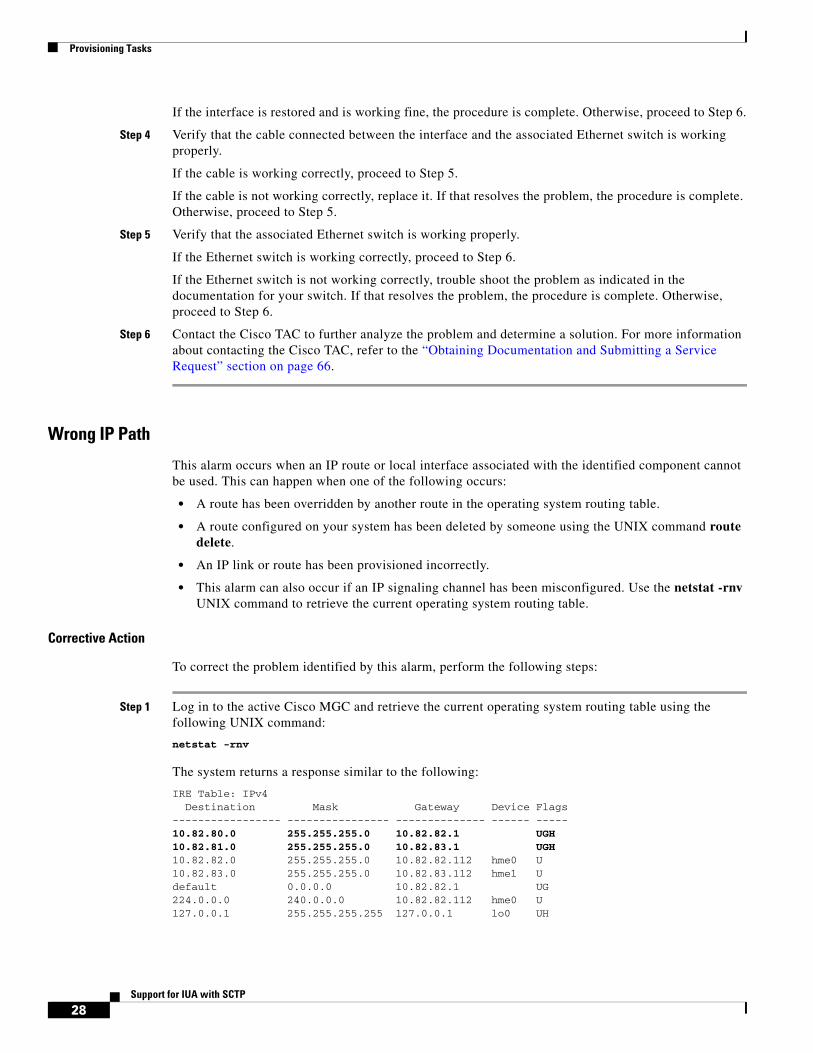
Wrong IP Path
This alarm occurs when an IP route or local interface associated with the identified component cannot be used. This can happen when one of the following occurs:
• A route has been overridden by another route in the operating system routing table.
• A route configured on your system has been deleted by someone using the UNIX command route delete.
• An IP link or route has been provisioned incorrectly.
• This alarm can also occur if an IP signaling channel has been misconfigured. Use the netstat -rnv UNIX command to retrieve the current operating system routing table.
Corrective Action
To correct the problem identified by this alarm, perform the following steps:
Step 1 Log in to the active Cisco MGC and retrieve the current operating system routing table using the following UNIX command:
netstat -rnv
The system returns a response similar to the following:
IRE Table: IPv4 Destination Mask Gateway Device Flags ----------------- ---------------- -------------- ------ ----- 10.82.80.0 255.255.255.0 10.82.82.1 UGH 10.82.81.0 255.255.255.0 10.82.83.1 UGH10.82.82.0 255.255.255.0 10.82.82.112 hme0 U 10.82.83.0 255.255.255.0 10.82.83.112 hme1 Udefault 0.0.0.0 10.82.82.1 UG224.0.0.0 240.0.0.0 10.82.82.112 hme0 U127.0.0.1 255.255.255.255 127.0.0.1 lo0 UH

Provisioning Tasks
29Support for IUA with SCTP
Step 2 If the response does not contain the route identified in the alarm, open the operating system routing table file using a text editor such as vi. Otherwise, proceed to Step 5.
Step 3 Add the route to the routing table using the appropriate text editor command.
Step 4 Save the file and exit the editing session. If this resolves the problem, the procedure is complete. Otherwise, proceed to Step 5.
Step 5 Verify that the provisioned settings for the identified IP link are correct, using the prov-rtrv MML command, as described in the “Retrieving Provisioning Data” section on page 13.
If the provisioned settings for your IP link are correct, proceed to Step 7.
If the provisioned settings for your IP link are incorrect, proceed to Step 6.
Step 6 Start a dynamic reconfiguration session to change the settings, as described in the “Invoking Dynamic Reconfiguration” section of the Cisco Media Gateway Controller Software Release 9 Operations, Maintenance, and Troubleshooting Guide. If this resolves the problem, the procedure is complete. Otherwise, proceed to Step 7.
Step 7 Contact the Cisco TAC to further analyze the problem and determine a solution. For more information about contacting the Cisco TAC, refer to the “Obtaining Documentation and Submitting a Service Request” section on page 66.
Signaling Channel Troubleshooting ProceduresThe following signaling channel troubleshooting procedures are new for this feature:
• Resolving an Association Alarm, page 29
• Setting the Service State of an Association, page 30
• Setting the Service State of an IP Route, page 30
Resolving an Association Alarm
If an alarm indicates a failure on an association, perform the following steps:
Step 1 If this alarm occurs along with a LIF FAIL alarm on the local IP address (ADDR1 and ADDR2), proceed to Step 2. Otherwise, proceed to Step 4.
Step 2 Verify the functioning of the cabling between the Cisco MGC and the LAN switch.
If the cables are functioning properly, proceed to Step 3.
If you find bad cable(s), replace them. If that resolves the problem, the procedure is complete. Otherwise, proceed to Step 3.
Step 3 Verify the functioning of the associated LAN switch. Refer to the documentation for your LAN switch for the necessary steps.
If the LAN switch is functioning properly, proceed to Step 6.
If the LAN switch is not functioning properly, refer to the appropriate troubleshooting procedures in the documentation for the LAN switch. If that corrects the problem, the procedure is complete. Otherwise, proceed to Step 6.
Step 4 Debug the IP connectivity between the Cisco MGC and the associated media gateway.

Provisioning Tasks
30Support for IUA with SCTP
If the IP connectivity is good, proceed to Step 5.
If the IP connectivity is bad, fix the identified problem. If that corrects the problem, the procedure is complete. Otherwise, proceed to Step 5.
Step 5 Determine the health of the associated media gateway.
If the media gateway is working correctly, proceed to Step 6.
If the media gateway is not healthy, fix the problem using the procedures in the user documentation for the media gateway. If that corrects the problem, the procedure is complete. Otherwise, proceed to Step 6.
Step 6 Contact the Cisco TAC to further analyze the problem and determine a solution. For more information about contacting the Cisco TAC, refer to the “Obtaining Documentation and Submitting a Service Request” section on page 66.
Setting the Service State of an Association
To change the service state of an association, log in to the active Cisco MGC, start an MML session, and enter the following command:
mml>set-association:assoc_name:serv_state[,confirm]
Where:
• assoc_name—MML name of the association you want to modify.
• serv_state—Service state to which you want to change. Valid values for IP links are IS, OOS, and FOOS.
• confirm—This parameter is required when you are setting the service state to OOS or FOOS.
Note This command cannot be used on the standby Cisco MGC.
For example, to set the service state of the association, assoc1, to OOS, enter the following command:
mml>set-association:assoc1:OOS,confirm
You can verify that the selected association is in the proper service state by performing the procedure in the “Retrieving the Service State for Associations” section on page 31.
Setting the Service State of an IP Route
To change the service state of an IP route, log in to the active Cisco MGC, start an MML session, and enter the following command:
mml>set-iproute:iproute_name:serv_state[,confirm]
Where:
• iproute_name—MML name of the IP route you want to modify.
• serv_state—Service state to which you want to change. Valid values for IP links are IS, OOS, and FOOS.
• confirm—This parameter is required when you are setting the service state to OOS or FOOS.

Monitoring and Maintaining - Regular Operations
31Support for IUA with SCTP
Note This command cannot be used on the standby Cisco MGC.
An IP route in any of the following combinations of primary and secondary service states can be set to OOS or FOOS:
• IS
• OOS, CONF
• OOS, OFF_DUTY
• OOS, STDBY
For an IP route to be set to IS, it must have a primary service state of OOS and a secondary service state of COOS.
For example, you enter the following command to set the service state of an IP route called iprte1 to OOS:
mml>set-iproute:iprte1:OOS,confirm
Note You can verify that the selected IP route is in the proper service state by performing the procedure in the “Retrieving the Service State for IP Routes” section on page 32.
Monitoring and Maintaining - Regular OperationsThe following sections contain the regular operational procedures you need to monitor and maintain this feature. For more information on operational tasks for the rest of the Cisco MGC software, refer to the Cisco Media Gateway Controller Software Release 9 Operations, Maintenance, and Troubleshooting Guide
Managing Signaling ChannelsThe following sections are new or modified for Release 9.4:
• Retrieving the Service State for Associations, page 31
• Retrieving the Service State for IP Routes, page 32
Retrieving the Service State for Associations
To retrieve the service state for an individual association, log in to the active Cisco MGC, start an MML session, and enter the following command:
mml>rtrv-association:assoc_name
For example, to retrieve the service state of an association called assoc1, enter the following command:
mml>rtrv-association:assoc1
The system returns a message similar to the following:
Media Gateway Controller 2000-03-26 20:26:18M RTRV "assoc1:IS"

Monitoring and Maintaining - Regular Operations
32Support for IUA with SCTP
To retrieve attributes for all of the associations, log in to the active Cisco MGC, start an MML session, and enter the following command:
mml>rtrv-association:all
The system returns a message similar to the following:
Media Gateway Controller 2000-03-26 19:23:23M RTRV "assoc1:OOS "assoc2:OOS "assoc3:OOS "assoc4:OOS
The valid service states for an association are described in the following sections. If the association is in any state other than IS, attempt to bring it into service, as described in the “Resolving an Association Alarm” section on page 29.
Association Primary Service States
The PST field shows the current primary service state of the association. Table 1 lists the valid primary service state values:
Association Secondary Service States
The SST field shows the current secondary service state of the specified association. Table 2 lists the valid secondary service state values:
Retrieving the Service State for IP Routes
To retrieve the service state for an individual IP route, log in to the active Cisco MGC, start an MML session, and enter the following command:
mml>rtrv-iproute:iproute_name
Table 1 Association Primary Service State Values
Link State ID Link State Description
INB Install busy When a system is first configured, all associations default to this state.
IS In-service Association is IS and fully operational. This is its normal operating state.
OOS Out-of-service Association is OOS. The system is actively trying to restore the association.
Table 2 Association Secondary Service State Values
Link State ID Link State Description
COOS Commanded out-of-service
Association has been commanded OOS by the operator.
STBY Standby Association on the standby Cisco MGC.
CONF Configuration Association is OOS due to a configuration failure.

Monitoring and Maintaining - Regular Operations
33Support for IUA with SCTP
For example, to retrieve the service state of an IP route called iprte1, enter the following command:
mml>rtrv-iproute:iprte1
The system returns a message similar to the following:
Media Gateway Controller 2000-03-26 20:26:18M RTRV "iprte1:IS"
To retrieve attributes for all of the IP routes, log in to the active Cisco MGC, start an MML session, and enter the following command:
mml>rtrv-iproute:all
The system returns a message similar to the following:
Media Gateway Controller 2000-03-26 19:23:23M RTRV "iprte1:IS "iprte2:IS
The valid service states for an IP route are described in the following sections. If the route is in any other state than IS, attempt to bring it into service, as described in the “Setting the Service State of an IP Route” section on page 30.
IP Route Primary Service States
The PST field shows the current primary service state of the IP route. Table 3 lists the valid primary service state values:
IP Route Secondary Service States
The SST field shows the current secondary service state of the specified IP route. Table 4 lists the valid secondary service state values:
Table 3 IP Route Primary Service State Values
Link State ID Link State Description
IS In-service Route is IS and fully operational. This is its normal operating state.
OOS Out-of-service Route is OOS. The system is actively trying to restore the link.
Table 4 IP Route Secondary Service State Values
Link State ID Link State Description
COOS Commanded out-of-service
Route has been commanded OOS by the operator.
STBY Standby Routes on the standby Cisco MGC.
OFF_DUTY Off duty Route is available for use, but not currently being used.
CONF Configuration Route is OOS due to a configuration failure.

Configuration Example
34Support for IUA with SCTP
Configuration ExampleThis section provides a configuration example for the XECfgParm.dat parameters associated with this feature. Additional configuration examples for the Cisco MGC software can be found in the Cisco Media Gateway Controller Software Release 9 Installation and Configuration Guide.
Note Configuration of XECfgParm.dat parameters for this feature is required only when the Cisco MGC hosts are not in the same subnet.
*.IP_NextHop1 = 147.21.135.10*.IP_NextHop2 = 147.15.170.11*.IP_NextHop3 = 0.0.0.0*.IP_NextHop4 = 0.0.0.0*.IP_NextHop5 = 0.0.0.0*.IP_NextHop6 = 0.0.0.0*.IP_NextHop7 = 0.0.0.0*.IP_NextHop8 = 0.0.0.0
Provisioning ExampleThis section provides a provisioning example for this feature. Additional provisioning examples for the Cisco MGC software can be found in the Cisco Media Gateway Controller Software Release 9 Provisioning Guide.
________________________________________; IP Route;;;;;;;;;;;;;;;;;;;;;;;;;;;;;;;;;;;;;;;;prov-add:IPROUTE:NAME="iprte1",DEST="10.82.80.0",NETMASK=”255.255.255.0”,NEXTHOP=”10.82.82.1”,IPADDR=”IP_Addr1”,DESC="IP Route 1"prov-add:IPROUTE:NAME="iprte2",DEST="10.82.81.0",NETMASK=”255.255.255.0”,NEXTHOP=”10.82.82.1”,IPADDR=”IP_Addr2”,DESC="IP Route 2"
________________________________________; SS7 External Node;;;;;;;;;;;;;;;;;;;;;;;;;;;;;;;;;;;;;;;;prov-add:EXTNODE:NAME="va-2600-165",TYPE="SLT",DESC="2611 SLT RUDP E1"prov-add:EXTNODE:NAME="va-2600-166",TYPE="SLT",DESC="2611 SLT RUDP E1"
________________________________________; Point Codes;;;;;;;;;;;;;;;;;;;;;;;;;;;;;;;;;;;;;;;;prov-add:OPC:NAME="opc",DESC="Own pointcode",NETADDR="1.1.3",NETIND=2,TYPE="TRUEOPC"prov-add:DPC:NAME="dpc1",DESC="Destination pointcode1",NETADDR="1.1.1",NETIND=2prov-add:DPC:NAME="dpc2",DESC="Destination pointcode2",NETADDR="1.1.2",NETIND=2
________________________________________; Signal Services to Inet via SLT;;;;;;;;;;;;;;;;;;;;;;;;;;;;;;;;;;;;;;;;prov-add:SS7PATH:NAME="ss7svc1",DESC="SS7 to dpc1",DPC="dpc1", OPC="opc", MDO="Q761_BASE"prov-add:SS7PATH:NAME="ss7svc2",DESC="SS7 to dpc2",DPC="dpc2", OPC="opc", MDO="Q761_BASE"
________________________________________; SS7 linksets;;;;;;;;;;;;;;;;;;;;;;;;;;;;;;;;;;;;;;;;prov-add:LNKSET:NAME="ls1",DESC="linkset 1 to dpc1",APC="dpc1",PROTO="SS7-ITU",TYPE="IP"prov-add:LNKSET:NAME="ls2",DESC="linkset 2 to dpc2",APC="dpc2",PROTO="SS7-ITU",TYPE="IP"

Provisioning Example
35Support for IUA with SCTP
________________________________________; SS7 route;;;;;;;;;;;;;;;;;;;;;;;;;;;;;;;;;;;;;;;;prov-add:SS7ROUTE:NAME="rte1",DESC="SS7 Rte 1-dpc1",OPC="opc",DPC="dpc1",LNKSET="ls1",PRI=1prov-add:SS7ROUTE:NAME="rte2",DESC="SS7 Rte 2-dpc2",OPC="opc",DPC="dpc2",LNKSET="ls2",PRI=1
________________________________________; Sessionset;;;;;;;;;;;;;;;;;;;;;;;;;;;;;;;;;;;;;;;;prov-add:SESSIONSET:NAME="slt1",ipaddr1="IP_Addr1",ipaddr2="IP_Addr2", PORT=7000, PEERADDR1="10.82.80.188",PEERADDR2="10.82.81.165",PEERPORT=7000,extnode="va-2600-165", TYPE=”BSMV0”,IPROUTE1="iprte1”, IPROUTE2="iprte2”
prov-add:SESSIONSET:NAME="slt2",ipaddr1="IP_Addr1",ipaddr2="IP_Addr2", PORT=7000,PEERADDR1="10.82.80.191",PEERADDR2="10.82.81.166",PEERPORT=7000, extnode="va-2600-166", TYPE=”BSMV0”,IPROUTE1="iprte1”, IPROUTE2="iprte2”
________________________________________; C7IPLinks;;;;;;;;;;;;;;;;;;;;;;;;;;;;;;;;;;;;;;;;prov-add:C7IPLNK:NAME="ls1lk1",DESC="SS7ANSI", LNKSET="ls1", SESSIONSET="slt1",SLC=0,PRI=1,TIMESLOT=0
prov-add:C7IPLNK:NAME="ls2lk1",DESC="SS7ANSI", LNKSET="ls2",SESSIONSET="slt1",SLC=0,PRI=1,TIMESLOT=2
prov-add:C7IPLNK:NAME="ls1lk2",DESC="SS7ANSI", LNKSET="ls1", SESSIONSET="slt2",SLC=1,PRI=1,TIMESLOT=0
prov-add:C7IPLNK:NAME="ls2lk2",DESC="SS7ANSI", LNKSET="ls2",SESSIONSET="slt2",SLC=1,PRI=1,TIMESLOT=2
;;;;;;;;;;;;;;;;;;;;;;;;;;;;;;;;;;;;;;;;; NAS External Node;;;;;;;;;;;;;;;;;;;;;;;;;;;;;;;;;;;;;;;;prov-add:EXTNODE:NAME="va-5400-36",TYPE="AS5400",DESC="RLM"prov-add:EXTNODE:NAME="va-5400-37",TYPE="AS5400",DESC="IUA NAS",ISDNSIGTYPE="IUA"
;;;;;;;;;;;;;;;;;;;;;;;;;;;;;;;;;;;;;;;;; SCTP Association;;;;;;;;;;;;;;;;;;;;;;;;;;;;;;;;;;;;;;;;prov-add:ASSOCIATION:NAME="nasassoc2",ipaddr1="IP_Addr1",ipaddr2="IP_Addr2", PEERADDR1="10.82.80.30",PEERADDR2="10.82.81.30", extnode="va-5400-37", TYPE="IUA",IPROUTE1="iprte1",IPROUTE2="iprte2"
prov-add:ASSOCIATION:NAME="dpnssassoc2",ipaddr1="IP_Addr3",ipaddr2="IP_Addr4", PEERADDR1="10.82.80.31",PEERADDR2="10.82.81.31", extnode="va-3660-20", TYPE="IUA",IPROUTE1="iprte1",IPROUTE2="iprte2"
;;;;;;;;;;;;;;;;;;;;;;;;;;;;;;;;;;;;;;;;; NAS Path;;;;;;;;;;;;;;;;;;;;;;;;;;;;;;;;;;;;;;;;prov-add:NASPATH:NAME="nassvc1",EXTNODE="va-5400-36", prov-add:NASPATH:NAME="nassvc2",EXTNODE="va-5400-37",SIGPORT=0,SIGSLOT=0
;;;;;;;;;;;;;;;;;;;;;;;;;;;;;;;;;;;;;;;;; NAS IP Links;;;;;;;;;;;;;;;;;;;;;;;;;;;;;;;;;;;;;;;;prov-add:IPLNK:NAME="nas1-lnk1",IF="hme0",IPADDR="IP_Addr1", PORT=3001, PEERADDR="10.82.80.29", PEERPORT=3001,PRI=1,IPROUTE="iprte1",SVC="nassvc1"
Command Reference
36Support for IUA with SCTP
prov-add:IPLNK:NAME="nas1-lnk2",IF="hme1",IPADDR="IP_Addr2", PORT=3001, PEERADDR="10.82.81.29", PEERPORT=3001, PRI=1, IPROUTE="iprte2",SVC="nassvc1"
Command ReferenceThis section documents new, modified, or deleted Man-Machine Language (MML) commands. All other MML commands are documented in the Cisco Media Gateway Controller Software Release 9 MML Command Reference Guide.
New MML CommandsThis section contains the MML commands that are new for this feature.
RTRV-ASSOCIATION—Display State of SCTP Association
Purpose: This MML command displays the primary and secondary states of an SCTP association.
Syntax: rtrv-association:assoc_namertrv-association:all
Input Description:
• Assoc_name—MML name of a previously configured SCTP association.
• All—All associations
Output Description:
SCTP Association—MML name of SCTP association specified.
PST—Primary state; valid values are:
– INB—Installed busy; association has been created but has not yet been commanded IS or OOS with the set-association command.
– IS—In service
– OOS—Out of service
SST—Secondary state; valid values are:
– COOS—Commanded out of service
– STBY—The local platform state is standby
– CONF—Out of service due to a configuration failure

Command Reference
37Support for IUA with SCTP
RTRV-IPROUTE—Display Primary and Secondary States of an IP Route
Example: The MML command shown in the following example retrieves the state of all associations:
mml>rtrv-association:all
MGC-01 - Media Gateway Controller 2001-01-01 18:57:26M RTRV"assoc1:IS""assoc2:OOS,COOS";
Comments: Performance Impact Category: A
Purpose: This MML command displays the primary and secondary states of an IP route.
Syntax: rtrv-iproute:ip_route_namertrv-iproute:all
Input Description:
• Ip_route_name—MML name of a previously configured IP route.
• All—Retrieves the primary state of all IP routes.
Output Description:
IP route—MML name of the specified IP route.
PST—Primary state; valid values are:
– IS—In service
– OOS—Out of service
SST—Secondary state; valid values are:
– COOS—Commanded out of service
– STBY—The local platform state is standby
– OFF_DUTY—The link is available for use but is not currently being used.
– CONF—The link is out of service due to a configuration failure.
Example: The MML command shown in the following example retrieves the state of all IP routes:
mml>rtrv-iproute:all MGC-01 - Media Gateway Controller 2002-06-25 15:13:40.983 ESTM RTRV "iproute1:IS" "iproute2:IS"
Comments: Performance Impact Category: A
Command Reference
38Support for IUA with SCTP
SET-ASSOCIATION—Changing Association Primary State
SET-IPROUTE—Changing IP Route Primary State
Modified MML CommandsThis section contains the MML commands that were modified for this feature.
Purpose: This MML command changes the primary state of an SCTP association.
Syntax: set-association:assoc_name:PST[,confirm]
Input Description:
• Assoc_name—MML name of a previously configured SCTP association.
• PST—Desired primary state; valid values are IS, OOS, or FOOS
• Confirm—Verify desired state. This parameter must be used when the primary state desired is OOS or FOOS
Example: The MML command shown in the following example changes the primary state of an association to out of service:
mml>set-association:assoc1:OOS,confirm
Comments: Performance Impact Category: A
Purpose: This MML command changes the primary and secondary states of an IP route.
Syntax: set-iproute:ip_route_name:pst[,confirm]
Input Description:
• IP_rout_name—MML name of a previously configured IP route.
• PST—Desired primary state; valid values are IS, OOS, or FOOS.
• Confirm—Must be used when you set the primary state to OOS or FOOS to verify the new state. An IP route in any of the following states can be commanded OOS or FOOS:
– IS
– OOS,CONF
– OOS,OFF_DUTY
– OOS,STBY
Example: The MML command shown in the following example changes the primary state of an IP route to out of service:
mml>set-iproute:iproute1:oos,confirm
Comments: Performance Impact Category: A

Command Reference
39Support for IUA with SCTP
PROV-ADD—Add Provisioning Component
Purpose: This MML command adds a component to the Cisco MGC configuration.
Syntax: prov-add:<comp>:name=”<MML name>”,<param name>=<param value>,...prov-add:lnksetprop:name=”<protocol family>”,<param name>=<param value>,...
Input Description:
• lnksetprop—MML NE component consisting of parameters for which you can tune linkset communications. See Appendix A of the Cisco Media Gateway Controller Software Release 9 Provisioning Guide for a list of linkset property parameters.
• comp—MML component type name for the type of configuration you are creating. It must match one of the component types listed in the Cisco Media Gateway Controller Software Release 9 Provisioning Guide. If <comp> is EXTNODE, then the <param name> TYPE must be present and must take a set of values (refer to the second example below).
• name—MML component name for the new object you are creating (as many as ten characters).
• protocol family—Name of the protocol family for which you are provisioning linkset properties. Use PROV-RTRV:VARIANTS to obtain a list of protocol families configured for your system.
• param name—The name of a valid configuration parameter for the specified component type. Parameter names are listed in the Cisco Media Gateway Controller Software Release 9 Provisioning Guide.
• param value—The value you want to assign to the parameter. If the parameter value is a string, it should be surrounded by quotation marks.
To define more than one parameter, enter additional param name=param value descriptions on the command line.
Example: The MML command shown in the following example adds the origination point code for the MGC configuration:
mml>PROV-ADD:opc:NAME="opc",DESC="Point code of CP1",netaddr="0.0.1", netind=2,type=”TRUEOPC”Media Gateway Controller - MGC-01 2000-01-12 15:19:51 M COMPLD"opc";
Example: The MML command shown in the following example adds an external node to the MGC configuration:
mml>PROV-ADD:EXTNODE:NAME="TOTO2",DESC="TATA",TYPE="MGX8260"Media Gateway Controller - MGC-02 2000-05-08 18:05:55M COMPLD"extnode";
Comments: Performance Impact Category: B
Refer to the Cisco Media Gateway Controller Software Release 9 Provisioning Guide for information about using the PROV commands for provisioning and for a description of components, parameter names, and parameter values used in provisioning the MGC.

Command Reference
40Support for IUA with SCTP
PROV-DLT—Delete Components or Parameters
PROV-ED—Modify Provisioned Component
Purpose: This MML command deletes a provisioned component.
Syntax: prov-dlt:<comp>:name=”<MML name>”prov-dlt:lnksetprop:name=”<protocol family>”
Input Description:
• lnksetprop—MML NE component consisting of parameters for which you can tune linkset communications. See Appendix A of the Cisco Media Gateway Controller Software Release 9 Provisioning Guide for a list of linkset property parameters.
• comp—MML component type name for the type of component you are modifying. The entered parameter must match one of the component types listed in the Cisco Media Gateway Controller Software Release 9 Provisioning Guide.
• name—MML name of the component you are modifying.
• protocol family—Name of the protocol family for which you are provisioning linkset properties. Use PROV-RTRV:VARIANTS to obtain a list of protocol families configured for your system.
Example: The MML command shown in the following example deletes the point code component "opc":
mml>PROV-DLT:opc:NAME="opc"Media Gateway Controller - MGC-01 2000-01-12 15:19:51 M COMPLD "opc" ;
Comments: Perform PROV-STA—Start Provisioning Session before using this command.
Performance Impact Category: B
Refer to the Cisco Media Gateway Controller Software Release 9 Provisioning Guide for information about using the PROV commands for provisioning and for a description of components, parameter names, parameters, and parameter values used in provisioning.
Purpose: This MML command modifies a provisioned component.
Note Enter only those parameters that need to be modified.
Syntax: prov-ed:<comp>:name=”<MML name>”,<param name>=<param value>,...prov-add:lnksetprop:name=”<protocol family>”,<param name>=<param value>,...

Command Reference
41Support for IUA with SCTP
RTRV-IPLNK—Display Primary and Secondary States of an IP Link
Input Description:
• lnksetprop—MML NE component consisting of parameters for which you can tune linkset communications. See Appendix A of the Cisco Media Gateway Controller Software Release 9 Provisioning Guide for a list of linkset property parameters.
• comp—MML component type of the component you are modifying. The entered parameter must match one of the component types listed in the Cisco Media Gateway Controller Software Release 9 Provisioning Guide.
• name—MML name for the component you are modifying. You cannot change the component name.
• protocol family—Name of the protocol family for which you are provisioning linkset properties. Use PROV-RTRV:VARIANTS for a list of protocol families configured for your system.
• param name—The name of each configuration parameter you want to change. The parameter names must be valid for the specified component type. Refer to the Cisco Media Gateway Controller Software Release 9 Provisioning Guide for a description of components, parameter names, parameter descriptions, and parameter values.
• param value—The new value you want to assign to the parameter. If the parameter value is a string, it should be surrounded by quotation marks.
Note To modify more than one parameter, enter additional param name=value descriptions on the command line.
Example: The MML command shown in the following example changes the description of the provisioned point code “opc”:
mml>PROV-ED:opc:NAME="opc", DESC="Point code for this SSP"Media Gateway Controller - MGC-01 2000-01-12 15:19:51 M COMPLD "opc" ;
Comments: Perform PROV-STA—Start Provisioning Session before using this command.
Performance Impact Category: B
Refer to the Cisco Media Gateway Controller Software Release 9 Provisioning Guide for information on using the PROV commands for provisioning and for a description of components, parameter names, and parameter values used in provisioning.
Purpose: This MML command displays the primary and secondary states of an IP link.
Syntax: rtrv-iplnk:ip_link_namertrv-iplnk:all
Input Description:
• IP_link_name—MML name of a previously configured IP link.
• All—Retrieves the primary state of all IP links.
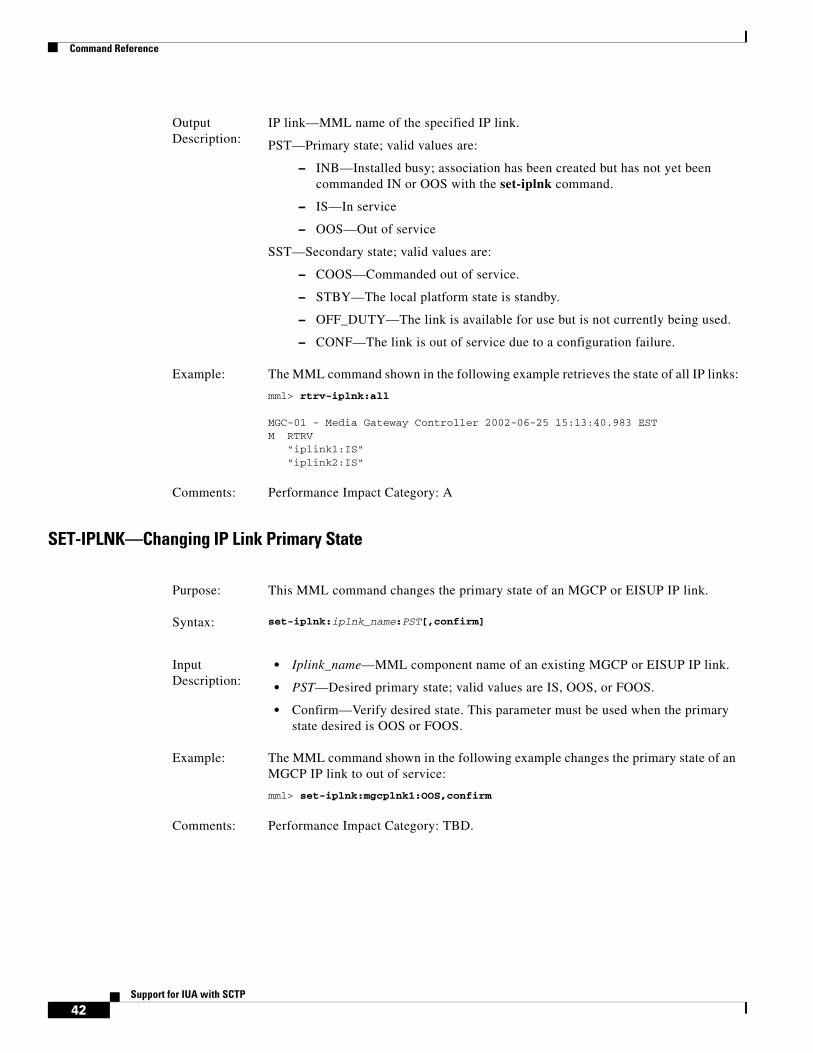
Command Reference
42Support for IUA with SCTP
SET-IPLNK—Changing IP Link Primary State
Output Description:
IP link—MML name of the specified IP link.
PST—Primary state; valid values are:
– INB—Installed busy; association has been created but has not yet been commanded IN or OOS with the set-iplnk command.
– IS—In service
– OOS—Out of service
SST—Secondary state; valid values are:
– COOS—Commanded out of service.
– STBY—The local platform state is standby.
– OFF_DUTY—The link is available for use but is not currently being used.
– CONF—The link is out of service due to a configuration failure.
Example: The MML command shown in the following example retrieves the state of all IP links:
mml> rtrv-iplnk:all
MGC-01 - Media Gateway Controller 2002-06-25 15:13:40.983 ESTM RTRV "iplink1:IS" "iplink2:IS"
Comments: Performance Impact Category: A
Purpose: This MML command changes the primary state of an MGCP or EISUP IP link.
Syntax: set-iplnk:iplnk_name:PST[,confirm]
Input Description:
• Iplink_name—MML component name of an existing MGCP or EISUP IP link.
• PST—Desired primary state; valid values are IS, OOS, or FOOS.
• Confirm—Verify desired state. This parameter must be used when the primary state desired is OOS or FOOS.
Example: The MML command shown in the following example changes the primary state of an MGCP IP link to out of service:
mml> set-iplnk:mgcplnk1:OOS,confirm
Comments: Performance Impact Category: TBD.

Reference Information
43Support for IUA with SCTP
Reference InformationThe following sections contain reference material related to this feature. Information is included in the following areas:
• XECfgParm.dat Parameters, page 43
• Alarms, page 44
• Measurements, page 46
• Components, page 48
• External Node Types, page 61
• Provisioning Worksheets, page 61
XECfgParm.dat ParametersThe XECfgParm.dat file configuration parameters added for this feature are in the table below.
Configuration Parameter Definition
*.IUA.maxNasExtNodes Specifies the maximum number of external nodes that can be defined with an ISDN signaling type of IUA. This number also represents the maximum number of IUA associations that can be provisioned.
Valid value: 256
Note Do not change this value.
*.IUA.maxNasPathsPerExtNode Specifies the maximum number of NAS signaling services that can be assigned to each external node with an ISDN signaling type of IUA.
Valid value: 112
Note Do not change this value.

Reference Information
44Support for IUA with SCTP
For information on the other XECfgParm.dat parameters, refer to the Cisco Media Gateway Controller Software Release 9 Installation and Configuration Guide.
AlarmsThis section lists the alarms that are added and modified to support this feature. For information on the other alarms for the Cisco MGC software, refer to the Cisco Media Gateway Controller Software Release 9 Messages Reference Guide.
New Alarms
The alarms that are added for this feature are listed below.
Association Degraded
Description A destination address of the association has failed, and the association is still in an UP state.
Severity Minor
Cause This alarm is reported when one of the association destination addresses has failed.
Type 1 (Communication error).
Action Refer to the “Association Degraded” section on page 25.
Association Fail
Description The SCTP association has failed.
Severity Major
Cause This alarm is reported when the destination node is out of service or there is an IP connectivity failure.
Type 1 (Communication error)
Action Refer to the “Association Fail” section on page 26.
*.IUA.maxNasPaths Specifies the maximum number of IUA signaling services that can be provisioned.
Valid value:1500
Note Do not change this value.
*.IP_NextHop1*.IP_NextHop2*.IP_NextHop3*.IP_NextHop4*.IP_NextHop5*.IP_NextHop6*.IP_NextHop7*.IP_NextHop8
Specifies the IP addresses of up to eight next hop counters. These IP addresses are used when the next hop router IP addresses on the Cisco PGW hosts do not match.
Default: 0.0.0.0
Valid values: An IP address expressed in dotted decimal notation.
Configuration Parameter Definition

Reference Information
45Support for IUA with SCTP
Wrong IP Path
Description The IP route or local interface provisioned for the specified component is not being used.
Severity Minor
Cause This alarm is reported when generic analysis cannot access the conditional route description table.
Type 1 (Communication error).
Action Refer to the “Wrong IP Path” section on page 28.
Modified Alarms
The alarms that are modified for this feature are listed below.
IP RTE CONF FAIL
Description IP route is out of service due to a configuration failure.
Severity Information
Cause This alarm is now generated against the IP route components instead of signal channel components It indicates that an IP route is out of service because of a configuration failure.
Type 1 (No error)
Action Refer to the “IP RTE CONF FAIL” section on page 26.
IP RTE FAIL
Description IP route is out of service. This alarm is now generated by IP route objects instead of the signal channel components.
Severity Information
Cause Indicates that an IP route is out of service.
Type 1 (No error)
Action Refer to the “IP RTE FAIL” section on page 26.
LIF FAIL
Description Line interface failure.
Severity Major
Cause This alarm is now generated against local interface components. The line interface (LIF) has failed. All physical lines to the Cisco MGC and local interface components can raise this alarm.
Type 4 (Equipment error alarm)
Action Refer to the “LIF FAIL” section on page 27.
M-OOS
Description Resource has been manually taken OOS.
Severity Minor
Cause A request has been made fir a software process not necessary for normal system operation to be taken manually OOS. This alarm is now generated against IP route components.
Type 1 (Communication alarm)

Reference Information
46Support for IUA with SCTP
Action Restore the process to the in-service state using the user interface. IP routes can be returned to service using the procedure in the “Setting the Service State of an IP Route” section on page 30.
MeasurementsTable 5 contains the system measurements that are added to support this feature. For information on the other system measurements, refer to the Cisco Media Gateway Controller Software Release 9 Operations, Maintenance, and Troubleshooting Guide.
Table 5 New Operational Measurements
MML Counter Group:Name DescriptionRelated Components
Logging Interval
IUA GROUP
IUA: ASPUpTx
IUA: ASPUpAckRx
IUA message statistics
Number of application server process (ASP) Up messages sent from the Cisco MGC to the media gateway on this SCTP association. These messages indicate that the Cisco MGC is ready to receive traffic or maintenance messages.
Number of ASP Up Acknowledgement messages received by the Cisco MGC from the media gateway on this SCTP association.
Association
15, 60, 24
15, 60, 24
IUA: ASPDnTx
IUA: ASPDnAckRx
IUA: ASPActTx
Number of ASP Down messages sent from the Cisco MGC to the media gateway on this SCTP association. These messages indicate that the Cisco MGC is not ready to receive traffic or maintenance messages.
Number of ASP Up Acknowledgement messages received by the Cisco MGC from the media gateway on this SCTP association.
Number of ASP Active messages sent from the Cisco MGC to the media gateway on this SCTP association. These messages indicate that the Cisco MGC is active.
15, 60, 24
15, 60, 24
15, 60, 24
IUA: ASPActAckRx
IUA: ASPInactTx
IUA: ASPInactAckRx
IUA: ErrorRx
Number of ASP Active Acknowledgement messages received by the Cisco MGC from the media gateway on this SCTP association.
Number of ASP Inactive messages sent from the Cisco MGC to the media gateway on this SCTP association. These messages indicate that the Cisco MGC is inactive.
Number of ASP Inactive Acknowledgement messages received by the Cisco MGC from the media gateway on this SCTP association.
Number of Error messages received by the Cisco MGC from the media gateway on this SCTP association.
15, 60, 24
15, 60, 24
15, 60, 24
15, 60, 24

Reference Information
47Support for IUA with SCTP
IUA: NotifyRx
IUA: DataRqt
Number of Notify messages received by the Cisco MGC from the media gateway on this SCTP association. These messages provide autonomous indications of IUA events on the media gateway.
Number of Data messages sent from the Cisco MGC to the media gateway on this SCTP association. Each messages is transmitted through the use of the Q.921 acknowledged information transfer service.
15, 60, 24
15, 60, 24
IUA GROUP (continued)
IUA: DataInd
IUA: UnitDataRqt
IUA: UnitDataInd
IUA message statistics (continued)
Number of Data messages received by the Cisco MGC from the media gateway on this SCTP association. Each message is received through the use of the Q.921 acknowledged information transfer service.
Number of Data messages sent from the Cisco MGC to the media gateway on this SCTP association. Each message is transmitted through the use of the Q.21 unacknowledged information transfer service.
Number of Data messages received by the Cisco MGC from the media gateway on this SCTP association. Each message is received through the user of the Q.21 unacknowledged information transfer service.
Association
15, 60, 24
15, 60, 24
15, 60, 24
IUA: EstRqt
IUA: EstConf
IUA: EstInd
IUA: RelRqt
IUA: RelConf
IUA: RelInd
Number of requests that an SCTP association be established.
Number of confirmations that IUA has established an SCTP association with the media gateway.
Number of times that the media gateway has informed Link Management that the Cisco MGC has established an SCTP association.
Number of requests for the release of an SCTP association with a media gateway.
Number of confirmations that IUA has released an SCTP association with the media gateway.
Number of times that the media gateway has informed Link Management that the Cisco MGC has released an SCTP association.
15, 60, 24
15, 60, 24
15, 60, 24
15, 60, 24
15, 60, 24
15, 60, 24
Table 5 New Operational Measurements
MML Counter Group:Name DescriptionRelated Components
Logging Interval

Reference Information
48Support for IUA with SCTP
ComponentsThe sections below discuss the provisioning components that are added and modified for this feature. For information on the rest of the components in the Cisco MGC software, refer to the Cisco Media Gateway Controller Software Release 9 Provisioning Guide.
New Components
The following provisioning components are added for this feature.
IP Route
The IP route component represents a static IP route. Its MML name is as follows:
• MML Name—IPROUTE
The IP route component structure is shown in Table 6.
SCTP-GROUP
SCTP: OOTB
SCTP: InvalidChksum
SCTP: CtrlTx
SCTP: OrdDataTx
SCTP: UnordDataTx
SCTP: CtrlRx
SCTP traffic statistics
Number of out of the blue packets received.
Number of checksum error packets received.
Number of control chunks sent.
Number of ordered data chunks sent.
Number of unordered data chunks sent.
Number of control chunks received.
Association
15, 60, 24
15, 60, 24
15, 60, 24
15, 60, 24
15, 60, 24
15, 60, 24
SCTP: OrdDataRx
SCTP: UnordDataRx
SCTP: DataSegTx
SCTP: DataSegRx
SCTP: AssocFailures
SCTP: DestFailures
SCTP: PeerRestarted
Number of ordered data chunks received.
Number of unordered data chunks received.
Number of SCTP data segments sent.
Number of SCTP data segments received.
Number of association failures.
Number of destination failures.
Number of peer restarts.
15, 60, 24
15, 60, 24
15, 60, 24
15, 60, 24
15, 60, 24
15, 60, 24
15, 60, 24
Table 5 New Operational Measurements
MML Counter Group:Name DescriptionRelated Components
Logging Interval
Table 6 IPROUTE Component Structure
Parameter MML Name Parameter Description Parameter Values (Default)
NAME Unique component name used in MML commands
The name can be as many as 20 alphanumeric characters. No special characters other than “-” are allowed. The name should begin with a letter.
DESC Component description The description can be up to 128 characters.

Reference Information
49Support for IUA with SCTP
Note NAME is the only parameter for this command that cannot be modified.
The following rules apply when you are creating or editing IP routes:
• Thesystem validates the NETMASK. For your provisioning setup to work correctly, its value (when converted to binary) must have at least one leading 1 and cannot have any trailing 1s after the first 0. For example, the values 255.255.0.0 and 255.255.255.128 are valid. The values 0.0.255.255, 255.0.0.255, and 0.0.0.0 are invalid.
• Ensure that the destination resolves to a non-zero address.
• When the resolved destination address is bit ORed with the netmask value, the result is equal to the netmask (for example, a destination of 10.11.12.13 and a netmask of 255.255.0.0 would be invalid because the ORed result would be 255.255.12.13, which is not equal to 255.255.0.0).
• The combination of DESTINATION, NETMASK, and IPADDR must be unique for each IP route.
• The combination of DESTINATION, NETMASK, and PRI must be unique for each IP route.
• When an IP route is specified in a link object (for example, IPLNK, SESSIONSET, or ASSOCIATION), the IP address resolved from the PEERADDR attribute is checked against the DESTINATION and NETMASK attributes to ensure the IPROUTE is valid.
• When an IP route is specified in a link object (for example, IPLNK, SESSIONSET, or ASSOCIATION), the IPADDR must match the IPADDR of the link.
• When an IP route is not specified for a link object, the IP address resolved from the PEERADDR attribute is checked against the defined IP routes to ensure that it should not be assigned an IP route. If the PEERADDR is on the same subnet as the DESTINATION (based on the NETMASK), and if the IPADDR matches the IPADDR of the link object, use an IP route.
• If the NEXTHOP attribute is a host name or symbolic name from XECfgParm.dat, it can resolve to the address 0.0.0.0, which indicates the IP route is not used. The IP route status shows up in the rtrv-iproute:all command output when in the OOS, OFF_DUTY state.
DEST Destination host name or IP address
IP Address in dotted decimal notation or hostname that is less than or equal to 32 characters.
NETMASK Subnet mask of Destination (optional)
IP Address in dotted decimal notation. (255.255.255.255)
NEXTHOP Next hop router IP address
IP Address or hostname that is less than or equal to 32 characters, or one of the following property names defined in XECfgParm.dat:
• IP_NextHop1
• IP_NextHop2
• IP_NextHop8
• IP_Addr1
• IP_Addr2
• IP_Addr4
IPADDR Local IP address IP_Addr1, IP_Addr2, IP_Addr3, or IP_Addr4.
PRI Priority 1 through 65535; (1)
Table 6 IPROUTE Component Structure (continued)

Reference Information
50Support for IUA with SCTP
• If the resolved NEXTHOP address is not 0.0.0.0, it must be on the same subnet of the IPADDR.
The commands to retrieve and set the service state of an IP route can be found in the “Retrieving the Service State for IP Routes” section on page 32 and the “Setting the Service State of an IP Route” section on page 30.
SCTP Association
The SCTP association component represents the connection between the Cisco MGC and a Cisco media gateway. Its MML name is as follows:
• MML Name—ASSOCIATION
The SCTP association component structure is shown in Table 7.
Table 7 Association Component Structure
Parameter MML Name Parameter Description Parameter Values (Default)
NAME Unique component name used in MML commands
The name can be up to 20 alphanumeric characters. No special characters other than “-” are allowed. The name should begin with an alphabetic character.
DESC Component description The name can be up to 128 alphanumeric characters. No special characters other than “-” are allowed. The name should begin with an alphabetic character.
TYPE Signaling Type The type of protocol to be used. Values: M3UA, SUA, and IUA
SGP MML name of an SGP (optional)
MML name of a previously configured SGP. Used for M3UA and SUA interfaces.
IPADDR1 First local address IP_Addr1, IP_Addr2, IP_Addr3, or IP_Addr4.
IPADDR2 Second local address (optional)
IP_Addr1, IP_Addr2, IP_Addr3, IP_Addr4, or N/A.
(N/A)
PORT Local SCTP port number (optional)
From 1024 through 65535.
Defaults to 9900 for IUA. Defaults to 2905 for M3UA. Defaults to 14001 for SUA.
PEERADDR1 The highest priority destination address
IP address
PEERADDR2 The lowest priority destination address (optional)
IP address; (0.0.0.0).
PEERPORT Destination SCTP port number. (optional)
From 1024 through 65535.
Defaults to 9900 for IUA. Defaults to 2905 for M3UA.Defaults to 14001 for SUA.
EXTNODE MML name of an external node (optional)
MML name of a previously configured external node. Used in IUA interfaces.

Reference Information
51Support for IUA with SCTP
IPROUTE1 MML name of first IPROUTE (optional)
MML name of a previously configured IPROUTE.
IPROUTE2 MML name of second IPROUTE (optional)
MML name of a previously configured IPROUTE.
RCVWIN Number of bytes to advertise for the local receive window. (optional)
From 1500 through 65535 (18000).
MAXINITRETRANS Maximum number of times to retransmit SCTP INIT message (optional)
0 through 100;(10)
0 means use SCTP internal default
MAXINITRTO Maximum initial timer retransmission value (optional)
0, 300 through 3000 (2000)
0 means use SCTP internal default.
MAXRETRANS Maximum number of retransmissions over all destination addresses before the association is declared failed (optional)
From 1 through 10 (5).
Note This value must not exceed MAXRETRANSDEST * the number of destinations.
CUMSACKTO Maximum time after a datagram is received before a SCPT SACK is sent (optional)
From 100 through 500 ms; (300).
BUNDLETO Maximum time SCTP will wait for other outgoing datagrams for bundling (optional)
From 100 through 600 ms; (100).
MINRTO Minimum value allowed for the retransmission timer (optional)
From 300 through 3000 ms; (300).
MAXRTO Maximum value allowed for the retransmission timer (optional)
From 1000 through 3000 ms; (3000).
HBTO Time between heartbeats. The heartbeat is this value plus the current retransmission timeout value (optional).
The value can be 0, or from 300 through 10000 ms; (2000).
0 means disabled.
Table 7 Association Component Structure (continued)
Parameter MML Name Parameter Description Parameter Values (Default)
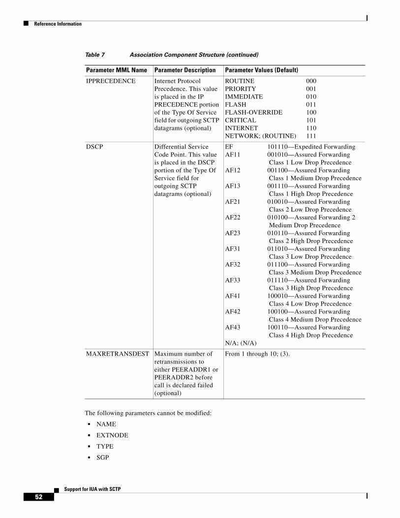
Reference Information
52Support for IUA with SCTP
The following parameters cannot be modified:
• NAME
• EXTNODE
• TYPE
• SGP
IPPRECEDENCE Internet Protocol Precedence. This value is placed in the IP PRECEDENCE portion of the Type Of Service field for outgoing SCTP datagrams (optional)
ROUTINE 000PRIORITY 001IMMEDIATE 010FLASH 011FLASH-OVERRIDE 100CRITICAL 101INTERNET 110NETWORK; (ROUTINE) 111
DSCP Differential Service Code Point. This value is placed in the DSCP portion of the Type Of Service field for outgoing SCTP datagrams (optional)
EF 101110—Expedited Forwarding AF11 001010—Assured Forwarding
Class 1 Low Drop PrecedenceAF12 001100—Assured Forwarding
Class 1 Medium Drop PrecedenceAF13 001110—Assured Forwarding
Class 1 High Drop PrecedenceAF21 010010—Assured Forwarding
Class 2 Low Drop PrecedenceAF22 010100—Assured Forwarding 2
Medium Drop PrecedenceAF23 010110—Assured Forwarding
Class 2 High Drop PrecedenceAF31 011010—Assured Forwarding
Class 3 Low Drop PrecedenceAF32 011100—Assured Forwarding
Class 3 Medium Drop PrecedenceAF33 011110—Assured Forwarding
Class 3 High Drop PrecedenceAF41 100010—Assured Forwarding
Class 4 Low Drop PrecedenceAF42 100100—Assured Forwarding
Class 4 Medium Drop PrecedenceAF43 100110—Assured Forwarding
Class 4 High Drop PrecedenceN/A; (N/A)
MAXRETRANSDEST Maximum number of retransmissions to either PEERADDR1 or PEERADDR2 before call is declared failed (optional)
From 1 through 10; (3).
Table 7 Association Component Structure (continued)
Parameter MML Name Parameter Description Parameter Values (Default)

Reference Information
53Support for IUA with SCTP
The following rules apply when you are creating or editing SCTP associations:
• Only one association with a type of IUA can be assigned to an external node.
• If the type of the association is IUA, the associated external node must have its ISDN signaling type set to IUA, and that external node must be able to support IUA signaling.
• If two associations have the same port value, the values of IPADDR1 and IPADDR2 must both be the same or both different.
• The values of IPADDR1 and IPADDR2 must be different.
• If the value of IPPRECEDENCE is not ROUTINE, the value of DSCP must be N/A.
• If the value of DSCP is not N/A, the value of IPPRECEDENCE must be ROUTINE.
• The value of MAXRTO must be greater than or equal to the value of MINRTO.
• When a peer IP address (PEERADDR1 or PEERADDR2) is not on the local subnet of IPADDR1 or IPADDR2, that peer IP address cannot be on the subnet of any other local interface, even if it is not defined within the Cisco MGC software.
• When a peer IP address (PEERADDR1 or PEERADDR2) is not on the local subnet of IPADDR1 or IPADDR2, an IP route (IPROUTE1 or IPROUTE2) must be specified. IPROUTE1 is specified for IPADDR1, and IPROUTE2 is specified for IPADDR2.
• When an IP route is specified, the values set in PEERADDR1 and PEERADDR2 are checked against the DESTINATION and NETMASK values of the IP route(s) to ensure that the IP route is valid.
• When an IP route is specified, its value for IPADDR must match the related IP address of the association. In other words, IPROUTE1 should have an IPADDR that matches IPADDR1 in the association, and IPROUTE 2 should have an IPADDR that matches IPADDR2 in the association.
• When an IP route is not specified, the IP address resolved from the PEERADDR1 or PEERADDR2 parameter is checked against the defined IP routes to see if it should be assigned to one of those IP routes. If the peer address is on the same subnet as an IP route, the link should use that IP route.
• The value of PEERADDR1 cannot be 0.0.0.0 or 255.255.255.255, and the value of PEERADDR2 cannot be 255.255.255.255.
• When a hostname is specified for a peer IP address, the hostname must resolve to an IP address.
• PEERADDR1 and PEERADDR2 can resolve to the same IP Address. If the external node only has one IP address and two IP addresses (IPADDR1 and IPADDR2) are defined, PEERADDR2 should be set to the same value as PEERADDR1.
• Associations, session sets, IP links, SIP links, and SS7 signaling gateway links that share a peer address (that is, PEERADDR, PEERADDR1, or PEERADDR2) must be assigned directly or indirectly to the same external node.
• When you are deleting an association, and a NASPATH uses the same external node, a warning message is issued to inform the you that the NASPATH must also be deleted. If it hasn't when the provisioning session is copied or deployed, an error message is generated and the copy or deployment is stopped.
• The value of PORT cannot be set to the same value as the PORT attribute of any IP link, session set, SIP link, or SS7 signaling gateway link.
• If a value for IPADDR2 or PEERADDR2 is specified, values for IPADDR1 or PEERADDR1 must also be specified. In other words, you cannot have one local address and two remote addresses, or two local addresses and one remote address.
• An IP link, session set, SS7 signaling gateway link, or an association with a different external or signaling gateway node cannot use the resolved value set in PEERADDR1 or PEERADDR2.

Reference Information
54Support for IUA with SCTP
• Only one association can be defined for an SS7 signaling gateway process (SGP).
• A value for EXTNODE can be defined only when the association type is IUA.
• A value for SGP can be defined only when the association type is M3UA or SUA.
• The maximum number of associations with a type of M3UA is defined in the XECfgParm.dat parameter, M3UA.maxSgp.
• The maximum number of associations with a type of SUA is defined in the XECfgParm.dat parameter, SUA.maxSgp.
The commands to retrieve and set the service state of an association can be found in the “Retrieving the Service State for Associations” section on page 31 and the “Setting the Service State of an Association” section on page 30.
Modified Components
The following components are modified for this feature.
External Node
The external node component represents another node with which the MGC communicates. Its MML name is as follows:
• MML Name—EXTNODE
The parameters for EXTNODE are defined in Table 8.
Note DESC is the only parameter for this command that can be modified:
The following rules apply when you are creating or editing external nodes:
• TYPE must be one of the valid external node types.
• The maximum number of external nodes with an ISDNSIGTYPE of IUA is 256.
Table 8 External Node Component Structure
Parameter MML Name Parameter Description Parameter Values (Default)
NAME MML name The name can be as many as 20 alphanumeric characters. No special characters other than “-” are allowed. The name should begin with a letter.
DESC Component description The description can be up to 128 characters.TYPE The type of the external node Valid values can be found in the “External Node
Types” section on page 61.ISDNSIGTYPE ISDN signaling type Valid values are IUA or N/A (default is N/A). This
parameter is added in software Release 9.4(1).GROUP M3UA/SUA group number Value is 1–100 for M3UA or SUA nodes. Value is 0
for nodes that do not support M3UA or SUA. This parameter is added in software Release 9.4(1).
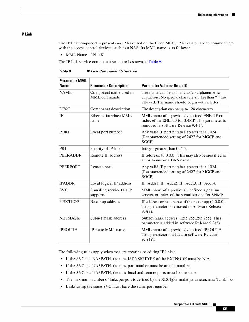
Reference Information
55Support for IUA with SCTP
IP Link
The IP link component represents an IP link used on the Cisco MGC. IP links are used to communicate with the access control devices, such as a NAS. Its MML name is as follows:
• MML Name—IPLNK
The IP link service component structure is shown in Table 9.
The following rules apply when you are creating or editing IP links:
• If the SVC is a NASPATH, then the ISDNSIGTYPE of the EXTNODE must be N/A.
• If the SVC is a NASPATH, then the port number must be an odd number.
• If the SVC is a NASPATH, then the local and remote ports must be the same.
• The maximum number of links per port is defined by the XECfgParm.dat parameter, maxNumLinks.
• Links using the same SVC must have the same port number.
Table 9 IP Link Component Structure
Parameter MML Name Parameter Description Parameter Values (Default)
NAME Component name used in MML commands
The name can be as many as 20 alphanumeric characters. No special characters other than “-” are allowed. The name should begin with a letter.
DESC Component description The description can be up to 128 characters.
IF Ethernet interface MML name
MML name of a previously defined ENETIF or index of the ENETIF for SNMP. This parameter is removed in software Release 9.4(1).
PORT Local port number Any valid IP port number greater than 1024 (Recommended setting of 2427 for MGCP and SGCP).
PRI Priority of IP link Integer greater than 0; (1).
PEERADDR Remote IP address IP address; (0.0.0.0). This may also be specified as a hos tname or a DNS name.
PEERPORT Remote port Any valid IP port number greater than 1024 (Recommended setting of 2427 for MGCP and SGCP)
IPADDR Local logical IP address IP_Addr1, IP_Addr2, IP_Addr3, IP_Addr4.
SVC Signaling service this IP supports
MML name of a previously defined signaling service or index of the signal service for SNMP.
NEXTHOP Next hop address IP address or host name of the next hop; (0.0.0.0). This parameter is removed in software Release 9.3(2).
NETMASK Subnet mask address Subnet mask address; (255.255.255.255). This parameter is added in software Release 9.3(2).
IPROUTE IP route MML name MML name of a previously defined IPROUTE. This parameter is added in software Release 9.4(1)T.
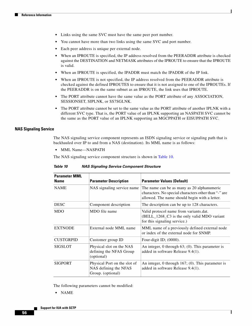
Reference Information
56Support for IUA with SCTP
• Links using the same SVC must have the same peer port number.
• You cannot have more than two links using the same SVC and port number.
• Each peer address is unique per external node.
• When an IPROUTE is specified, the IP address resolved from the PEERADDR attribute is checked against the DESTINATION and NETMASK attributes of the IPROUTE to ensure that the IPROUTE is valid.
• When an IPROUTE is specified, the IPADDR must match the IPADDR of the IP link.
• When an IPROUTE is not specified, the IP address resolved from the PEERADDR attribute is checked against the defined IPROUTES to ensure that it is not assigned to one of the IPROUTEs. If the PEERADDR is on the same subnet as an IPROUTE, the link uses that IPROUTE.
• The PORT attribute cannot have the same value as the PORT attribute of any ASSOCIATION, SESSIONSET, SIPLNK, or SS7SGLNK.
• The PORT attribute cannot be set to the same value as the PORT attribute of another IPLNK with a different SVC type. That is, the PORT value of an IPLNK supporting an NASPATH SVC cannot be the same as the PORT value of an IPLNK supporting an MGCPPATH or EISUPPATH SVC.
NAS Signaling Service
The NAS signaling service component represents an ISDN signaling service or signaling path that is backhauled over IP to and from a NAS (destination). Its MML name is as follows:
• MML Name—NASPATH
The NAS signaling service component structure is shown in Table 10.
The following parameters cannot be modified:
• NAME
Table 10 NAS Signaling Service Component Structure
Parameter MML Name Parameter Description Parameter Values (Default)
NAME NAS signaling service name The name can be as many as 20 alphanumeric characters. No special characters other than “-” are allowed. The name should begin with a letter.
DESC Component description The description can be up to 128 characters.
MDO MDO file name Valid protocol name from variants.dat. (BELL_1268_C3 is the only valid MDO variant for this signaling service.)
EXTNODE External node MML name MML name of a previously defined external node or index of the external node for SNMP.
CUSTGRPID Customer group ID Four-digit ID; (0000).
SIGSLOT Physical slot on the NAS defining the NFAS Group (optional)
An integer, 0 through 63; (0). This parameter is added in software Release 9.4(1).
SIGPORT Physical Port on the slot of NAS defining the NFAS Group. (optional)
An integer, 0 through 167; (0). This parameter is added in software Release 9.4(1).

Reference Information
57Support for IUA with SCTP
• EXTNODE
The following rules apply when creating or editing NAS signaling paths:
• You must have an IP link configured if the ISDNTYPE of the EXTNODE is N/A.
• The maximum number of DPNSSPATHs and IUA NASPATHs per IUA external node is 112.
• The maximum number of DPNSSPATHs and IUA NASPATHs is 1500.
• The SIGPORT and SIGSLOT attributes can be defined only if the ISDNTYPE of EXTNODE is IUA.
• An ASSOCIATION must be defined with the same EXTNODE attribute as its parent NASPATH. If this ASSOCIATION is not defined when the NASPATH is added or edited, a warning is issued. If the ASSOCIATION still is not defined when the provisioning session is copied or deployed, an error message is generated, and the copy or deployment procedure is stopped.
• If the ASSOCIATION with the same EXTNODE value as the NASPATH is deleted, a warning message is issued informing the user that the NASPATH must also be deleted. If it is not deleted when the provisioning session is copied or deployed, an error message is generated and the copy or deployment procedure is stopped.
Session Set
The session set component represents a pair of backhaul IP links used on the Cisco MGC. These links are used to communicate with external nodes that support IPFAS. Its MML name is as follows:
• MML Name—SESSIONSET
The session set component structure is shown in Table 11.
Table 11 Session Set Component Structure
Parameter MML Name Parameter Description Parameter Values (Default)
NAME Session set name The name can be as many as 20 alphanumeric characters. No special characters other than “-” are allowed. The name should begin with a letter.
DESC Component description The description can be up to 128 characters.
IPADDR1 Local logical IP address 1 IP_Addr1, IP_Addr2, IP_Addr3, or IP_Addr4
IPADDR2 Local logical IP address 2 IP_Addr1, IP_Addr2, IP_Addr3, or IP_Addr4
PORT Local port number 1025 through 65535.
PEERADDR1 Remote IP address 1 IP address; (0.0.0.0). This can also be specified as a host name or a DNS name.
PEERADDR2 Remote IP address 2 IP address; (0.0.0.0). This can also be specified as a host name or a DNS name.
PEERPORT Remote port 1025 through 65535.
EXTNODE External node MML name MML name of a previously configured external node.
NEXTHOP1 Next hop address 1 IP address or host name of the next hop; (0.0.0.0). This parameter is removed in Release 9.4(1).
NETMASK1 Subnet mask address 1 Subnet mask address; (255.255.255.255). This parameter is removed in Release 9.4(1).
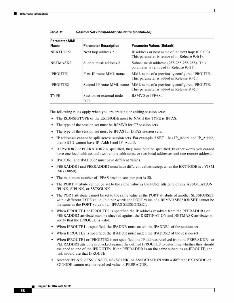
Reference Information
58Support for IUA with SCTP
The following rules apply when you are creating or editing session sets:
• The ISDNSIGTYPE of the EXTNODE must be N/A if the TYPE is IPFAS.
• The type of the session set must be BSMV0 for C7 session sets.
• The type of the session set must be IPFAS for IPFAS session sets.
• IP addresses cannot be split across session sets. For example if SET 1 has IP_Addr1 and IP_Addr2, then SET 2 cannot have IP_Addr1 and IP_Addr3.
• If IPADDR2 or PEERADDR2 is specified, they must both be specified. In other words you cannot have one local address and two remote addresses, or two local addresses and one remote address.
• IPADDR1 and IPADDR2 must have different values.
• PEERADDR1 and PEERADDR2 must have different values except when the EXTNODE is a VISM (MGX8850).
• The maximum number of IPFAS session sets per port is 50.
• The PORT attribute cannot be set to the same value as the PORT attribute of any ASSOCIATION, IPLNK, SIPLNK, or SS7SGLNK.
• The PORT attribute cannot be set to the same value as the PORT attribute of another SESSIONSET with a different TYPE value. In other words the PORT value of a BSMV0 SESSIONSET cannot be the same as the PORT value of an IPFAS SESSIONSET.
• When IPROUTE1 or IPROUTE2 is specified the IP address resolved from the PEERADDR1 or PEERADDR2 attribute must be checked against the DESTINATION and NETMASK attributes to verify that the IPROUTE is valid.
• When IPROUTE1 is specified, the IPADDR must match the IPADDR1 of the session set.
• When IPROUTE2 is specified, the IPADDR must match the IPADDR2 of the session set.
• When IPROUTE1 or IPROUTE2 is not specified, the IP address resolved from the PEERADDR1 or PEERADDR2 attribute is checked against the defined IPROUTES to determine whether they should assigned to one of the IPROUTEs. If the PEERADDR is on the same subnet as an IPROUTE, the link should use that IPROUTE.
• Another IPLNK, SESSIONSET, SS7SGLNK, or ASSOCIATION with a different EXTNODE or SGNODE cannot use the resolved value of PEERADDR.
NEXTHOP2 Next hop address 2 IP address or host name of the next hop; (0.0.0.0). This parameter is removed in Release 9.4(1).
NETMASK2 Subnet mask address 2 Subnet mask address; (255.255.255.255). This parameter is removed in Release 9.4(1).
IPROUTE1 First IP route MML name MML name of a previously configured IPROUTE. This parameter is added in Release 9.4(1).
IPROUTE2 Second IP route MML name MML name of a previously configured IPROUTE. This parameter is added in Release 9.4(1).
TYPE Sessionset external node type
BSMV0 or IPFAS.
Table 11 Session Set Component Structure (continued)
Parameter MML Name Parameter Description Parameter Values (Default)
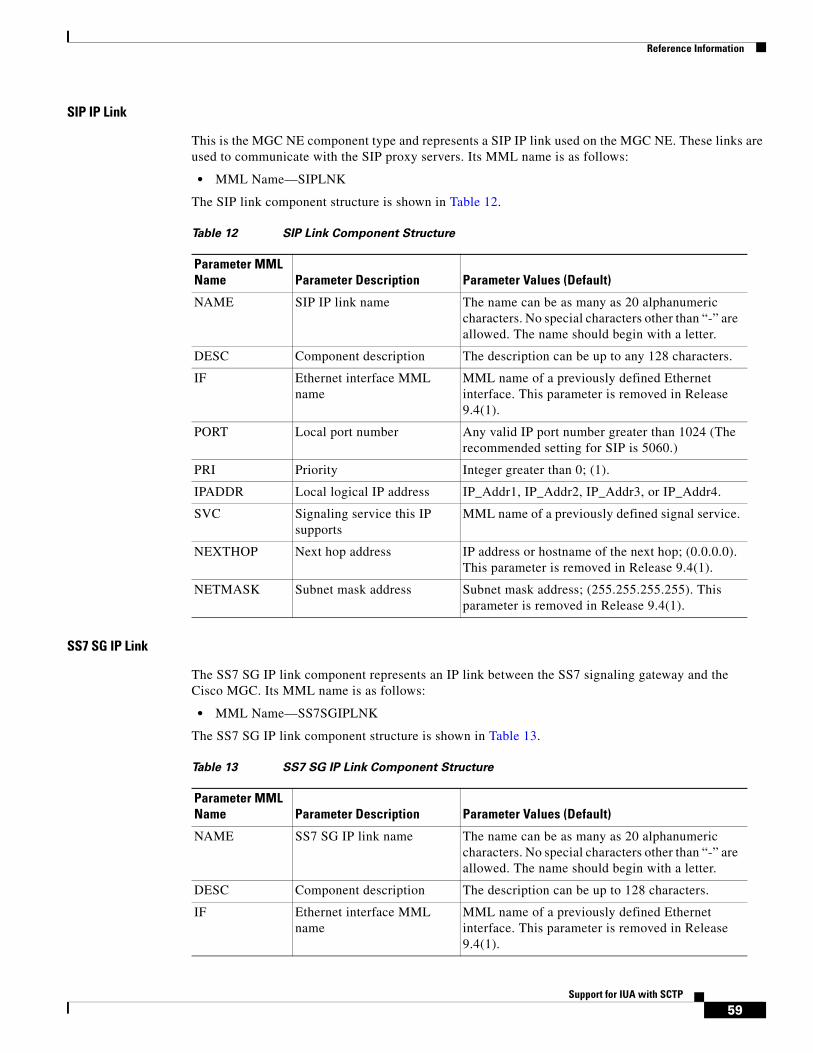
Reference Information
59Support for IUA with SCTP
SIP IP Link
This is the MGC NE component type and represents a SIP IP link used on the MGC NE. These links are used to communicate with the SIP proxy servers. Its MML name is as follows:
• MML Name—SIPLNK
The SIP link component structure is shown in Table 12.
SS7 SG IP Link
The SS7 SG IP link component represents an IP link between the SS7 signaling gateway and the Cisco MGC. Its MML name is as follows:
• MML Name—SS7SGIPLNK
The SS7 SG IP link component structure is shown in Table 13.
Table 12 SIP Link Component Structure
Parameter MML Name Parameter Description Parameter Values (Default)
NAME SIP IP link name The name can be as many as 20 alphanumeric characters. No special characters other than “-” are allowed. The name should begin with a letter.
DESC Component description The description can be up to any 128 characters.
IF Ethernet interface MML name
MML name of a previously defined Ethernet interface. This parameter is removed in Release 9.4(1).
PORT Local port number Any valid IP port number greater than 1024 (The recommended setting for SIP is 5060.)
PRI Priority Integer greater than 0; (1).
IPADDR Local logical IP address IP_Addr1, IP_Addr2, IP_Addr3, or IP_Addr4.
SVC Signaling service this IP supports
MML name of a previously defined signal service.
NEXTHOP Next hop address IP address or hostname of the next hop; (0.0.0.0). This parameter is removed in Release 9.4(1).
NETMASK Subnet mask address Subnet mask address; (255.255.255.255). This parameter is removed in Release 9.4(1).
Table 13 SS7 SG IP Link Component Structure
Parameter MML Name Parameter Description Parameter Values (Default)
NAME SS7 SG IP link name The name can be as many as 20 alphanumeric characters. No special characters other than “-” are allowed. The name should begin with a letter.
DESC Component description The description can be up to 128 characters.
IF Ethernet interface MML name
MML name of a previously defined Ethernet interface. This parameter is removed in Release 9.4(1).

Reference Information
60Support for IUA with SCTP
The following rules apply when you are creating or editing SS7 SG IPLNKs:
• When you specify an IPROUTE, the IP address resolved from the PEERADDR attribute is checked against the DESTINATION and NETMASK attributes of the IPROUTE to ensure that the IPROUTE is valid.
• When an IPROUTE is specified, the IPADDR value must match the IPADDR value of the link.
• When an IPROUTE is not specified, the IP address resolved from the PEERADDR attribute is checked against the defined IPROUTES to ensure that it should not be assigned to one of the IPROUTEs. If the PEERADDR is on the same subnet as an IPROUTE, then the link should use that IPROUTE.
• The PORT attribute cannot be set to the same value as the PORT attribute of any ASSOCIATION, IPLNK, SESSIONSET, or SS7SGLNK.
• There is a maximum of two links allowed per SGNODE.
Deleted Components
The following components are obsolete as of Release 9.4(1):
• CARD
• FASPATH
• TDMIF
• TDMLNK
PORT Local port number Any valid IP port number greater than 1024.
PRI Priority An integer greater than 0: (1)
PEERADDR Remote IP address IP address; (0.0.0.0). This may also be specified as a hostn ame or a DNS name.
PEERPORT Remote port Any valid IP port number greater than 1024.
Note This field is ignored by the TIOS subsystems at this time.
The peerport value is contained in the XECfgParm field stPort. It is currently set to 32767.
IPADDR Local logical IP address IP_Addr1, IP_Addr2, IP_Addr3, or IP_Addr4
SLC Signaling link code 0 through 15; (1)
SGNODE SG node MML name MML name of a previously defined SG Node.
NEXTHOP Next hop address IP address or hostname of the next hop; (0.0.0.0). This parameter is removed in Release 9.4(1).
NETMASK Subnet mask address Subnet mask address; (255.255.255.255). This parameter is removed in Release 9.4(1).
IPROUTE IP route MML name MML name of a previously configured IPROUTE. This parameter is added in Release 9.4(1).
Table 13 SS7 SG IP Link Component Structure (continued)
Parameter MML Name Parameter Description Parameter Values (Default)
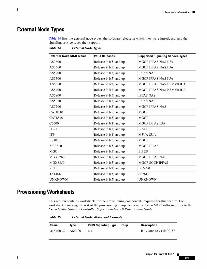
Reference Information
61Support for IUA with SCTP
External Node TypesTable 14 lists the external node types, the software release in which they were introduced, and the signaling service types they support.
Provisioning WorksheetsThis section contains worksheets for the provisioning components required for this feature. For worksheets covering the rest of the provisioning components in the Cisco MGC software, refer to the Cisco Media Gateway Controller Software Release 9 Provisioning Guide.
Table 14 External Node Types
External Node MML Name Valid Releases Supported Signaling Service Types
AS3600 Release 9.1(5) and up MGCP IPFAS NAS IUA
AS3660 Release 9.1(5) and up MGCP IPFAS NAS IUA
AS5200 Release 9.1(5) and up IPFAS NAS
AS5300 Release 9.1(5) and up MGCP IPFAS NAS IUA
AS5350 Release 9.2(2) and up MGCP IPFAS NAS BSMV0 IUA
AS5400 Release 9.2(2) and up MGCP IPFAS NAS BSMV0 IUA
AS5800 Release 9.1(5) and up IPFAS NAS
AS5850 Release 9.1(5) and up IPFAS NAS
AS7200 Release 9.1(5) and up MGCP IPFAS NAS
CAT8510 Release 9.1(5) and up MGCP
CAT8540 Release 9.1(5) and up MGCP
C2600 Release 9.4(1) and up MGCP IPFAS IUA
H323 Release 9.1(5) and up EISUP
ITP Release 9.4(1) and up M3UA SUA
LS1010 Release 9.1(5) and up MGCP
MC3810 Release 9.1(5) and up MGCP IPFAS
MGC Release 9.1(5) and up EISUP
MGX8260 Release 9.1(5) and up MGCP IPFAS NAS
MGX8850 Release 9.1(5) and up MGCP SGCP IPFAS
SLT Release 9.2(2) and up BSMV0
TALISS7 Release 9.1(5) and up SS7SG
UNKNOWN Release 9.1(5) and up UNKNOWN
Table 15 External Node Worksheet Example
Name Type ISDN Signaling Type Group Description
va-5400-37 AS5400 iua IUA conn to va-5400-37
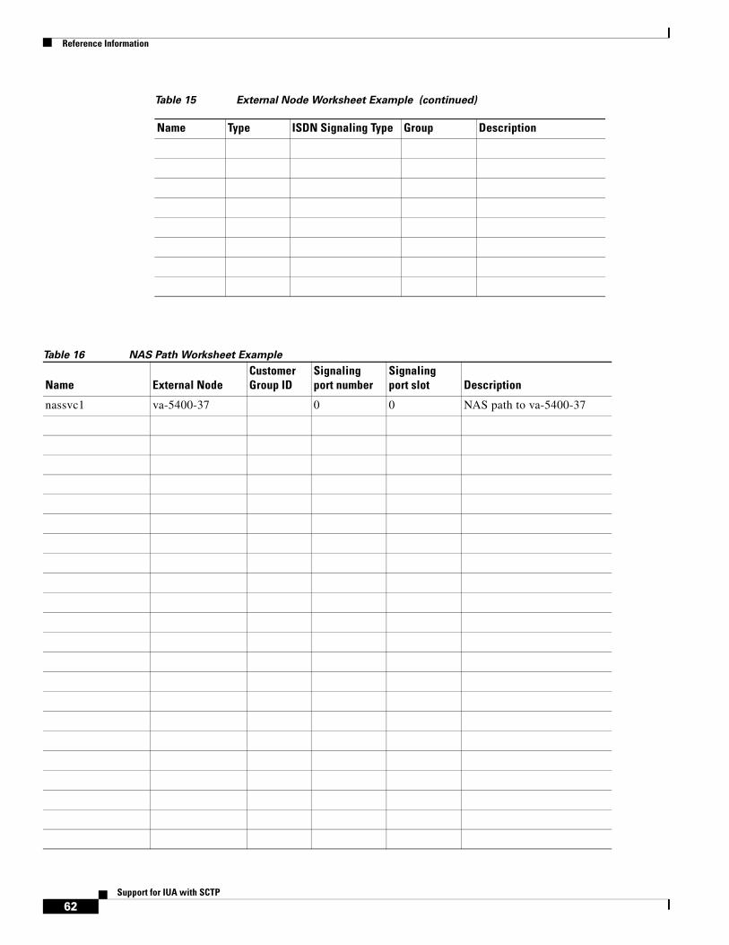
Reference Information
62Support for IUA with SCTP
Table 16 NAS Path Worksheet Example
Table 15 External Node Worksheet Example (continued)
Name Type ISDN Signaling Type Group Description
Name External NodeCustomer Group ID
Signaling port number
Signaling port slot Description
nassvc1 va-5400-37 0 0 NAS path to va-5400-37

Reference Information
63Support for IUA with SCTP
Name External NodeCustomer Group ID
Signaling port number
Signaling port slot Description
Table 17 IP Route Worksheet Example (optional)
Name Destination Subnet Mask Next Hop IP Address Priority Description
iproute1 va-5400-37 255.255.255.0 va-5400-36 175.25.211.17 1 IP route to va-5400-37
Table 18 SCTP Association Worksheet Example
Parameter Parameter Value
Name nasassoc1
Description NAS IUA association 1
Signaling Type IUA
SGP name
First local address IP_Addr1
Second local address (optional)
IP_Addr2
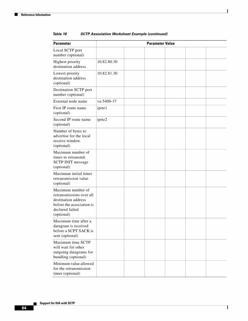
Reference Information
64Support for IUA with SCTP
Local SCTP port number (optional)
Highest priority destination address
10.82.80.30
Lowest priority destination address (optional)
10.82.81.30
Destination SCTP port number (optional)
External node name va-5400-37
First IP route name (optional)
iprte1
Second IP route name (optional)
iprte2
Number of bytes to advertise for the local receive window. (optional)
Maximum number of times to retransmit SCTP INIT message (optional)
Maximum initial timer retransmission value (optional)
Maximum number of retransmissions over all destination address before the association is declared failed (optional)
Maximum time after a datagram is received before a SCPT SACK is sent (optional)
Maximum time SCTP will wait for other outgoing datagrams for bundling (optional)
Minimum value allowed for the retransmission timer (optional)
Table 18 SCTP Association Worksheet Example (continued)
Parameter Parameter Value
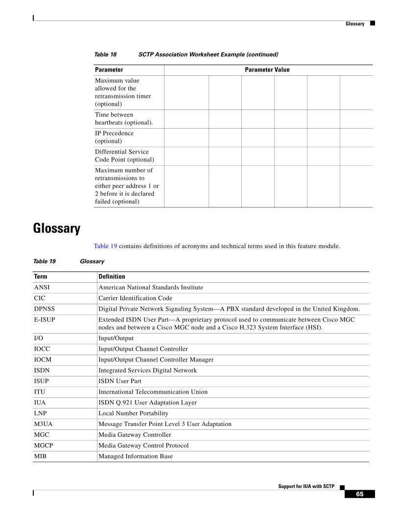
Glossary
65Support for IUA with SCTP
GlossaryTable 19 contains definitions of acronyms and technical terms used in this feature module.
Maximum value allowed for the retransmission timer (optional)
Time between heartbeats (optional).
IP Precedence (optional)
Differential Service Code Point (optional)
Maximum number of retransmissions to either peer address 1 or 2 before it is declared failed (optional)
Table 18 SCTP Association Worksheet Example (continued)
Parameter Parameter Value
Table 19 Glossary
Term Definition
ANSI American National Standards Institute
CIC Carrier Identification Code
DPNSS Digital Private Network Signaling System—A PBX standard developed in the United Kingdom.
E-ISUP Extended ISDN User Part—A proprietary protocol used to communicate between Cisco MGC nodes and between a Cisco MGC node and a Cisco H.323 System Interface (HSI).
I/O Input/Output
IOCC Input/Output Channel Controller
IOCM Input/Output Channel Controller Manager
ISDN Integrated Services Digital Network
ISUP ISDN User Part
ITU International Telecommunication Union
IUA ISDN Q.921 User Adaptation Layer
LNP Local Number Portability
M3UA Message Transfer Point Level 3 User Adaptation
MGC Media Gateway Controller
MGCP Media Gateway Control Protocol
MIB Managed Information Base

Obtaining Documentation and Submitting a Service Request
66Support for IUA with SCTP
Obtaining Documentation and Submitting a Service RequestFor information on obtaining documentation, submitting a service request, and gathering additional information, see the monthly What’s New in Cisco Product Documentation, which also lists all new and revised Cisco technical documentation, at:
http://www.cisco.com/en/US/docs/general/whatsnew/whatsnew.html
Subscribe to the What’s New in Cisco Product Documentation as a Really Simple Syndication (RSS) feed and set content to be delivered directly to your desktop using a reader application. The RSS feeds are a free service and Cisco currently supports RSS version 2.0.
CCDE, CCENT, Cisco Eos, Cisco HealthPresence, the Cisco logo, Cisco Lumin, Cisco Nexus, Cisco StadiumVision, Cisco TelePresence, Cisco WebEx, DCE, and Welcome to the Human Network are trademarks; Changing the Way We Work, Live, Play, and Learn and Cisco Store are service marks; and Access Registrar, Aironet, AsyncOS, Bringing the Meeting To You, Catalyst, CCDA, CCDP, CCIE, CCIP, CCNA, CCNP, CCSP, CCVP, Cisco, the Cisco Certified Internetwork Expert logo, Cisco IOS, Cisco Press, Cisco Systems, Cisco Systems Capital, the Cisco Systems logo, Cisco Unity, Collaboration Without Limitation, EtherFast, EtherSwitch, Event Center, Fast Step, Follow Me Browsing, FormShare, GigaDrive, HomeLink, Internet Quotient, IOS, iPhone, iQuick Study, IronPort, the IronPort logo, LightStream, Linksys, MediaTone, MeetingPlace, MeetingPlace Chime Sound, MGX, Networkers, Networking Academy, Network Registrar, PCNow, PIX, PowerPanels, ProConnect, ScriptShare, SenderBase, SMARTnet, Spectrum Expert, StackWise, The Fastest Way to Increase Your Internet Quotient, TransPath, WebEx, and the WebEx logo are registered trademarks of Cisco Systems, Inc. and/or its affiliates in the United States and certain other countries.
All other trademarks mentioned in this document or website are the property of their respective owners. The use of the word partner does not imply a partnership relationship between Cisco and any other company. (0812R)
MML Man-Machine Language
MTP3 Message Transfer Point Level 3
NAS Network media gateway
NFAS Non-Facility Associated Signaling
PSTN Public Switched Telephone Network
Q.931 ITU Document that defines the ISDN connection control protocol.
Q.921 ITU Document that defines the data link protocol used on an ISDN D-channel. Also known as Link Access Protocol - D Channel (LAPD)
RFC Return For Comment—A proposed standards document. There are RFCs for both IUA and SCTP.
RLM Redundant Link Manager—A proprietary protocol used for the transport of Q.931 data between a Cisco MGC host and an associated media gateway.
SCCP Signaling Connection Control Part
SCTP Stream Controlled Transmission Protocol
SIGTRAN Signaling Transport—An IETF working group that addresses the transport of packet-based PSTN signaling over IP networks.
SIP Session Initiation Protocol
SS7 Signaling System 7
SUA SCCP User Adaptation
TALI Transport Adapter Layer Interface
TCAP Transaction Capabilities Application Part
UDP User Datagram Protocol
Table 19 Glossary (continued)
Term Definition

Obtaining Documentation and Submitting a Service Request
67Support for IUA with SCTP

Obtaining Documentation and Submitting a Service Request
68Support for IUA with SCTP