support and bracing requirements for ceiling suspension
TRANSCRIPT

Approved by Chief Building Official Chu Chang, Building Division, City of San José
#24 – PLAN REVIEW NOTE April 22, 2016
Support and Bracing Requirements for Ceiling Suspension Systems with Lay-in Panels
Guidelines for architects, engineers, plan review staff and inspectors regarding the installation of ceiling suspension systems with lay- in panels.
CODE REFERENCE
• CBC 808.1 • CBC 1613.1 • ASCE 7-10 13.3.1 • ASCE 13.5.6 • ASTM C635 • ASTM C636 • ASTM E580
BACKGROUND
CBC 808.1 requires suspension ceiling systems to be installed in accordance with ASTM C635 and ASTM C636.
CBC 1613.1 requires suspension ceiling systems to be designed and constructed to resist the effects of earthquake motions in accordance with ASCE 7-10.
ASCE 7-10 13.3.1 provides formulas to determine and distribute horizontal seismic design forces; ASCE7-10 13.5.6 refers ASTM C635, ASTM C636, and ASTM E580 Section 5 as standards in Seismic Design Categories D, E and F for the design and installation of suspension ceiling systems with a few modifications.
Since ASTM C635, ASTM C636 and ASTM E 580 are not readily available, this note will compile the most common requirements as guidelines for design, plan review and inspection of the installation of ceiling suspension systems with lay-in panels. This note will also clarify the lateral bracing requirements for tenant improvement projects.
FINDINGS
1. Ceiling suspension system components: Suspension system components shall comply with ASTM C635 and Section 5.1 of ASTM E580. 1.1. Only heavy-duty main tees as defined by ASTM C635 shall be used as main runners. A heavy-duty runner shall
be adequate to support 16 PLF of uniformly distributed load over a 4 feet long simply supported span without the mid-span deflection exceeding 0.133 inch.
1.2. Suspension wires shall be minimum No.12 gauge, soft annealed, and galvanized mild steel wires. 1.3. Main runners, cross runners and their splices, intersection connectors, and expansion devices shall be designed
to carry a mean ultimate test load of not less than 180 lbs in compression and tension (ASTM E580 Section 5.1.2).
2. Seismic separation joints and penetrations
2.1. For ceiling areas exceeding 2500 square feet, a seismic separation joint shall be provided to divide the ceiling into areas not exceeding 2500 square feet and having a ratio of the long to short dimension not greater than 4:1. Each ceiling area shall be capable to allow ¾ inch movement, installed and braced per this guideline sections 3 and 4 below.
2.2. Except where rigid bracing is used or substantiating design calculations have shown that lateral deflections are limited to less than 0.25 inch, sprinkler heads and other penetrations shall have a 2-inches oversize ring, sleeve, or adapter through the ceiling tile to allow for free movement or at least 1 inch in all horizontal directions. Alternatively, a flexible sprinkler hose fitting that can accommodate 1 inch of ceiling movement shall be permitted to be used without the oversized ring, sleeve, or adapter.
3. Ceiling suspension system installation: The suspension system shall be installed in compliance with ASTM C636 and Section 5.2 of ASTM E580. 3.1. To support dead load and live load of a ceiling suspension system, No.12 gauge hanger wire shall be spaced at 4
feet on center and shall be attached to main runners unless calculations justifying the increased spacing are approved by plan check engineer.
3.2. Provide No.12 gauge hanger wires at the ends of each main and cross runners within 8 inches of the support. 3.3. The width of the perimeter supporting closure angle shall be not less than 2 inches.
Exception: supporting closure angle narrower than 2” may be used if the assembly of a closure angle and a wall attachment clip is approved by ICC equivalent to 2-inch-wide perimeter supporting angle required by Section 5.2.2 of ASTM E580 for the 2013 CBC for Seismic Design Categories D, E and F.
3.4. Main runner and cross runner ends shall be attached to the perimeter on two adjacent walls. A clearance of ¾ inch shall be maintained between the main runner and cross runner ends and the perimeter members on the two opposite walls. On other walls where terminal end runners are not fixed to the perimeter supporting closure, allow for ¾ inch movement.
3.5. The terminal ends of main runners and cross runners not attached to the perimeter closure angle or channel shall be prevented from spreading. A metal spreader strut or a No.16 gauge wire with a positive mechanical connection to the runner may be used for this purpose.
4. Lateral force bracing requirements 4.1. In other than Group E and I occupancies or risk category III & IV buildings, lateral force bracing is required per
this Section when ceiling area is greater than 1000 square feet. In Group E and I occupancies and risk category III & IV buildings, lateral force bracing is required per this Section when ceiling area is greater than 144 square feet.
Exception: Regardless the occupancy types and risk category of an existing building, providing lateral force bracing per this Section may be exempted for tenant improvement projects with ceiling area greater than 1000 square feet, provided all the following conditions are met: 1) Every individually altered ceiling area is less than 144 square feet; and 2) The accumulated ceiling alteration area within a room or space is less than 15% of the ceiling area
within the room or space where the alterations occur; and 3) The altered support and bracing elements shall match existing or stronger.
4.2. Lateral force bracing assembly shall consist of a compression strut and four (4) No.12 gauge bracing wires splayed 90 degrees from each other at an angle not exceeding 45 degree from the plane of the ceiling. The wires shall be secured to the main runners within 2 inches of the cross-runner intersection.
4.3. Lateral force bracing assembly shall be spaced at maximum 12 feet on center in both directions with the first point within 6 feet from each surrounding wall. Lateral force bracing assembly shall be also provided at the edges of any ceiling vertical offsets.
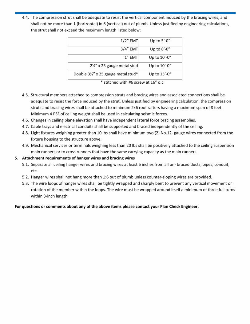
4.4. The compression strut shall be adequate to resist the vertical component induced by the bracing wires, and shall not be more than 1 (horizontal) in 6 (vertical) out of plumb. Unless justified by engineering calculations, the strut shall not exceed the maximum length listed below:
1/2” EMT Up to 5’-0”
3/4” EMT Up to 8’-0”
1” EMT Up to 10’-0”
2½” x 25 gauge metal stud Up to 10’-0”
Double 3⅝” x 25 gauge metal stud* Up to 15’-0”
* stitched with #6 screw at 16” o.c.
4.5. Structural members attached to compression struts and bracing wires and associated connections shall be adequate to resist the force induced by the strut. Unless justified by engineering calculation, the compression struts and bracing wires shall be attached to minimum 2x6 roof rafters having a maximum span of 8 feet. Minimum 4 PSF of ceiling weight shall be used in calculating seismic forces.
4.6. Changes in ceiling plane elevation shall have independent lateral force bracing assemblies. 4.7. Cable trays and electrical conduits shall be supported and braced independently of the ceiling. 4.8. Light fixtures weighing greater than 10 lbs shall have minimum two (2) No.12- gauge wires connected from the
fixture housing to the structure above. 4.9. Mechanical services or terminals weighing less than 20 lbs shall be positively attached to the ceiling suspension
main runners or to cross runners that have the same carrying capacity as the main runners. 5. Attachment requirements of hanger wires and bracing wires
5.1. Separate all ceiling hanger wires and bracing wires at least 6 inches from all un- braced ducts, pipes, conduit, etc.
5.2. Hanger wires shall not hang more than 1:6 out of plumb unless counter-sloping wires are provided. 5.3. The wire loops of hanger wires shall be tightly wrapped and sharply bent to prevent any vertical movement or
rotation of the member within the loops. The wire must be wrapped around itself a minimum of three full turns within 3-inch length.
For questions or comments about any of the above items please contact your Plan Check Engineer.
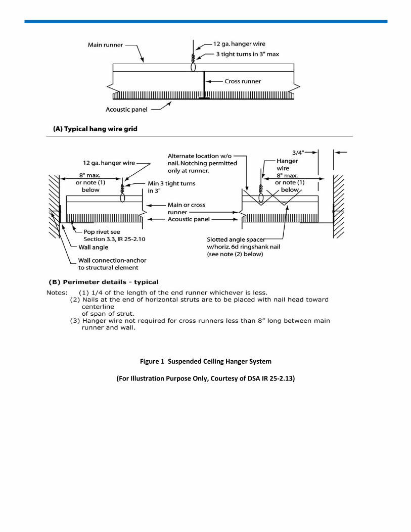
Figure 1 Suspended Ceiling Hanger System
(For Illustration Purpose Only, Courtesy of DSA IR 25-2.13)
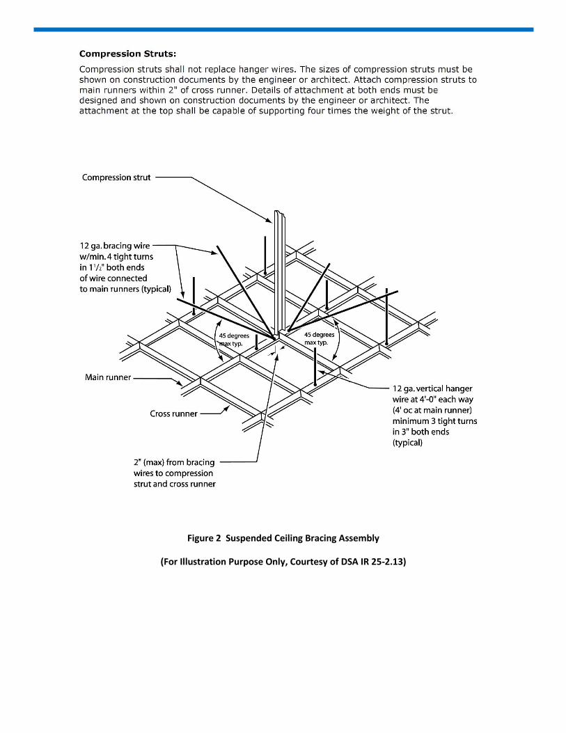
Figure 2 Suspended Ceiling Bracing Assembly
(For Illustration Purpose Only, Courtesy of DSA IR 25-2.13)