supplier document requirement listing …...piping and instrument diagrams x p+6 nf x o x x x c02...
TRANSCRIPT
ASSET:
FCP NUMBER:
FCP TITLE:
PO NUMBER:
DOCUMENT TYPE: SUPPLIER DOCUMENT REQUIREMENT LIST
DOCUMENT NUMBER:
DOCUMENT TITLE:
SUPPLIER:
Rev. Issued Date Reason for Issue Originator Approver
SUPPLIER DOCUMENT REQUIREMENT LISTING(SDRL)

WITH FIRST FINALBID ISSUE ISSUE
A B C D E F G H I J K L MCAT CAT A CONTROL DOCUMENTS
A01 SUPPLIER DOCUMENT REGISTER X P+1 OA02 PRODUCTION SCHEDULE (2 WKS) X P+2 OA03 PROGRESS REPORT X P+2 OA04 SUB VENDOR LIST X P+2 OA05 TABLE OF CONTENTS J01 X P+2 O XA06 TABLE OF CONTENTS K01 X P+2 O XA99 A99-MISCELLANEOUS CONTROL DOCUMENTS X O
CAT CAT B ARRANGEMENTSB01 GENERAL ARRANGEMENT DRAWINGS X P+4 NF X O X X XB02 ACCEPTANCE NOZZLE LOAD X P+12 O XB03 INTERFACE AND CONNECTION SCHEDULE X P+6 NF O XB04 FOUNDATION LOADING DIAGRAM AND SUPPORT DETAILS X P+12 NF O XB05 BASE-PLATE DETAILS X P+4 NF O X XB06 LIFTING EQUIPMENT GENERAL ARRANGEMENTS X P+4 NF O X XB99 MISCELLANEOUS ARRANGEMENTS X O X
CAT CAT C SYSTEM DIAGRAMS AND DATA SHEETSC01 PIPING AND INSTRUMENT DIAGRAMS X P+6 NF X O X X XC02 HVAC SCHEMATIC AND FLOW DIAGRAMS X P+12 NF X O X XC03 SINGLE LINE ELECTRICAL DISTRIBUTION DIAGRAMS X P+6 NF X O X XC04 BILL OF MATERIALS X P+4 O XC05 INSTRUMENT/TELECOMMS SYSTEM SCHEMATIC DIAGRAM X P+4 NF O XC06 UTILITY SCHEDULE X P+4 O XC07 WEIGHT DATA SHEETS X P+4 NF X O X XC08 EQUIPMENT DATA SHEETS X P+2 NF X O X XC09 INSTRUMENT DATA SHEETS X P+6 NF X O X XC10 ELECTRICAL DATA SHEETS X P+6 NF X O X XC11 SCHEDULE OF ELECTRICAL EQUIPMENT IN HAZARDOUS AREAS X P+6 O XC12 ELECTRICAL / ELECTRONIC / PNEUMATIC / HYDRAULIC SCHEMATICS X P+6 NF O XC13 DETAILED DESCRIPTION OF OPERATION X P+6 O XC14 PROCESS FLOW DIAGRAMS AND HEAT AND MASS BALANCE X P+6 NF X O X XC15 ELECTRICAL POWER SUPPLY REQUIREMENTS DATA SHEETS X P+6 NF O XC16 ENCLOSURE VENTILATION REQUIREMENTS DATA SHEETS X P+6 NF O XC17 CAUSE & EFFECT DRAWINGS X P+6 NF X O X XC18 DETAILED PARTS LIST X P+6 O XC99 MISCELLANEOUS SYSTEM DIAGRAMS AND DATA SHEETS X NF X O X
CAT CAT D DETAIL DRAWINGSD01 CROSS SECTION / EXPLODED VIEW DRAWINGS WITH PARTS LIST X P+4 NF O XD02 MECHANICAL SEAL DRAWINGS X P+4 NF O XD03 SHAFT ALIGNMENT DRAWINGS X P+4 NF O XD04 NAME PLATE FORMAT DRAWINGS X P+4 NF O XD05 CE NAMEPLATE FORMAT DRAWINGS X P+4 NF O XD06 SUB-ASSEMBLY DRAWINGS X P+4 NF O XD07 INSTALLATION & DISMANTLING DRAWING X P+4 NF O XD08 INSULATION / LINING DETAILS X P+4 NF O XD09 SHOP DETAIL DRAWING X P+6 NF O XD99 MISCELLANEOUS DETAIL DRAWINGS X P+4 NF O X X
CAT CAT E INSTRUMENT AND ELECTRICAL DRAWINGSE01 ELECTRICAL CONNECTION DIAGRAM X P+6 NF X O X XE02 INSTRUMENT / ELECTRICAL PANEL DETAIL DRAWING X P+6 NF O XE03 INSTRUMENT / ELECTRICAL LOGIC DIAGRAM X P+6 NF X O X XE04 TERMINAL BLOCK DIAGRAM X P+6 NF X O X XE05 CABLE SCHEDULE X P+6 NF X O X XE06 INSTRUMENT TERMINATION AND HOOK-UP DETAILS X P+6 NF X O X XE07 INSTRUMENT LOOP DIAGRAMS X P+6 NF X O X XE08 INSTRUMENT INDEX/SCHEDULE X P+6 NF O XE09 SPECIFICATIONS DO NOT USE (Obsolete) X O XE10 TRACE HEATING DRAWINGS X P+6 NF X O X XE11 INSTRUMENT / ELECTRICAL LAYOUT DRAWINGS X P+6 NF O XE99 MISCELLANEOUS INSTRUMENT/ELECTRICAL DRAWINGS X O X
CAT CAT F CALCULATIONS AND PERFORMANCE DATAF01 AVAILABILITY / RELIABILITY CALCULATIONS X O XF02 FUNCTIONAL AND DETAILED DESIGN SPECIFICATIONS X O XF03 DESIGN CALCULATIONS (see multiple Long Descriptions ) X O XF04 PERFORMANCE CURVES (see multiple Long Descriptions ) X O XF05 HYDRAULIC CALCULATIONS X O XF06 LATERAL CRITICAL SPEED CALCULATIONS X O XF07 TORSIONAL CRITICAL SPEED CALCULATIONS X O XF08 MOTOR PERFORMANCE CURVES X O X XF09 PUMP PERFORMANCE CURVES (see multiple Long Descriptions) X O XF10 SPEED/TORQUE STARTING CURVES X O X XF11 NOISE LEVEL DATA SHEETS X P+6 O XF12 EMISSIONS DATA SHEETS X P+2 O XF13 STRUCTURAL/LIFTING CALCULATIONS X O XF14 VALVES SIZING CALCULATIONS X O XF15 MECHANICAL CALCULATIONS X O XF16 PROCESS / UTILITY CALCULATIONS X O XF17 INSTRUMENT & CONTROL CALCULATIONS X O XF18 HEAT EMMISSION CALCULATIONS X O XF19 ENCLOSURE VENTILATION SYSTEM CALCULATIONS X O XF20 EXHAUST DUCT CALCULATIONS X O XF21 PIPING STRESS / PERFORMANCE ANALYSIS DATA (see multiple Long Descriptions ) X O XF22 CONTROL PHILOSOPHY & BLOCK LOGIC DIAGRAMS X P+6 NF O XF23 OPERATING PHILOSOPHY X P+6 O XF24 ELECTRICAL RELAY CHARACTERISTICS X O XF25 ACTUATION TORQUE / THRUST SIZING CALCULATIONS X O XF99 MISCELLANEOUS CALCULATIONS AND PERFORMANCE DATA X O
CAT CAT G HANDLINGG01 ERECTION AND INSTALLATION PROCEDURE X O XG02 UNPACKING AND PRESERVATION PROCEDURE X O XG03 PACKING, HANDLING AND SHIPPING PROCEDURE X O XG04 COSHH DATA SHEET X O XG05 ELASTOMER CURE DATE/CERTIFICATE (no less than 75% of shelf life remaining) X O XG99 MISCELLANEOUS HANDLING DOCUMENTATION X O
CAT CAT H MANUFACTURING AND QUALITY PROCEDURESH01 QUALITY MANUAL P+2 S XH02 QUALITY PLAN X P+2 O XH03 HYDROSTATIC TEST PROCEDURE X O XH04 DETAIL FABRICATION DRAWINGS/WELD MAP (+) X P+4 NF X O X X XH05 CORROSION TESTING PROCEDURE X O XH06 WELD PROCEDURE SPECIFICATIONS / WELD PROCEDURE QUALIFICATION RECORDS X O XH07 NON-DESTRUCTIVE EXAMINATION PROCEDURE X O XH08 HEAT TREATMENT PROCEDURE X O XH09 HYDROSTATIC / FLUSHING / PNEUMATIC TEST PROCEDUREH10 PERFORMANCE / ACCEPTANCE TEST PROCEDURE-FAT, SAT and/or UAT X O XH11 SURFACE PREPARATION AND PAINTING PROCEDURES X O XH12 SOFTWARE QUALITY SYSTEM VERIFICATION X O XH13 WEIGHING PROCEDURE X O XH14 LOAD TEST PROCEDURE X O XH15 INSPECTION & TEST PLAN X P+2 O XH99 MISCELLANEOUS MANUFACTURING AND QUALITY PROCEDURES X O
CAT CAT J COMMISSIONING, OPERATING AND MAINTENANCE INFORMATION
Review ClassR/C or
I
Req'd (Y)
AS-BUILD
WITHINMANUAL
DOCUMENTS REQUIRED
NF=NATIVE FILEHC=HARD COPYSC=SCAN PDF
ASSET NUMBER
REQD
REVIEW LOCATION
J01 K01
DATE REQ'D
SDRL TEMPLATE_rev1.xls Page 2 of 4

WITH FIRST FINALBID ISSUE ISSUE
A B C D E F G H I J K L M
Review ClassR/C or
I
Req'd (Y)
AS-BUILD
WITHINMANUAL
DOCUMENTS REQUIRED
NF=NATIVE FILEHC=HARD COPYSC=SCAN PDF
ASSET NUMBER
REQD
REVIEW LOCATION
J01 K01
DATE REQ'D
J01 OPERATING & MAINTENANCE MANUALS INCLUDING FULL PARTS LIST X 2 x HC + SC X OJ02 LUBE OIL OPERATING FLUIDS SCHEDULE INCL. FLUID/MATERIAL CONSUMPTION X P+10 O XJ03 SPARE PARTS & INTERGANGEABILITY RECORD (SPIR) - START-UP / COMMISSIONING / INSURANCE SPARES LIST AND SPECIAL
TOOLS X P+10 O XJ04 SPARE PARTS & INTERGANGEABILITY RECORD (SPIR) - TWO YEAR OPERATING SPARES X P+4 O XJ05 ERECTION FASTENERS SUMMARY LIST X O XJ06 PRE-COMMISSIONING / COMMISSIONING PROGRAMME X O XJ07 PRE-COMMISSIONING / COMMISSIONING PROCEDURE MANUAL X O XJ08 MASTER EQUIPMENT LIST (MEL) X NF OJ99 MISCELLANEOUS COMMISSIONING/OPERATING/MAINTENANCE INFORMATION X O X
CAT CAT K CERTIFICATIONK01 CERTIFICATION DATA BOOK X 2 x HC + SC X OK02 ATEX / IECE HAZARDOUS AREA CERTIFICATION AND SCHEDULE X P+2 O XK03 PERFORMANCE TEST REPORT X O XK04 FACTORY ACCEPTANCE TEST REPORT (FAT) X O XK05 VIBRATION REPORT X O XK06 NOISE REPORT X O XK07 CE DECLARATIONS OF CONFORMITY X S XK08 WEIGHT REPORT X S XK09 LOAD TEST RESULTS X S XK10 CERTIFICATE OF CONFORMITY (BS EN 10204 2.1) (*) X S XK11 BS EN 10204 - 2.2 MATERIAL CERTIFICATE X S XK12 BS EN 10204 - 3.1 MATERIAL CERTIFICATE X S XK13 BS EN 10204 - 3.2 MATERIAL CERTIFICATE X S XK14 CERTIFICATE OF COMPLIANCE (E.G VESSEL CODE) X S XK15 WELDABILITY DATA X O XK99 MISCELLANEOUS CERTIFICATION X O X
CAT CAT L TEST AND INSPECTION REPORTSL01 L01 - MATERIAL TEST CERT.-MILL CERTIFICATES (BSEN.10204 3.1; 3.2; 2.1; 2.2 ) DO NOT USE, replaced by K10, K11, K12, K13L02 WELDER PERFORMANCE QUALIFICATIONS X S XL03 NON-DESTRUCTIVE EXAMINATION OPERATOR QUALIFICATIONS X S XL04 PRODUCTION TEST RESULTS (including welding) X S XL05 NON-DESTRUCTIVE EXAMINATION RECORDS X S XL06 HEAT TREATMENT RECORDS X S XL07 MATERIAL TRACEABILITY RECORDS X S XL08 NAME PLATE/CE MARK RUBBING / PHOTOGRAPHS X O XL09 PRESSURE TEST CERTIFICATES WITH CHARTS (Hydrostatic and Pneumatic) X S XL10 INSTRUMENT TEST AND CALIBRATION CERTIFICATES X S XL11 DIMENSIONAL REPORT X S XL12 LIFTING EQUIPMENT TEST CERTIFICATES X S XL13 VESSEL / EXCHANGER CODE DATA REPORTS X S XL14 ELECTRICAL EQUIPMENT TYPE TESTS X S XL15 ROUTE TEST CERTIFICATES - ELECTRICAL MACHINERY DO NOT USE (Obsolete)L16 HIGH VOLTAGE IMPULSE TEST DO NOT USE (Obsolete)L17 INSULATION RESISTANCE TEST DO NOT USE (Obsolete)L18 MEASUREMENT OF RESISTANCE DO NOT USE (Obsolete)L19 PURCHASERS RELEASE NOTE / WAIVERS X S XL20 VERIFICATION BODY / INDEPENDENT COMPETENT PERSON(S) RELEASE NOTE X S XL21 PAINTING/INSULATION INSPECTION RECORD X S XL22 CONCESSION RECORDS / EQ'S X O XL23 FIRE TEST REPORTS / CERTIFICATES X S XL24 DESIGN DEVIATION REQUEST (DDR) O XL25 SITE SURVEY REPORT X S XL26 VALVE SEAT SEALING AND VALVE PRESSURE TEST RECORDS X S XL27 EARTH CONTINUITY TEST RECORDS X S XL28 TYPE APPROVAL CERTIFICATE X S XL29 VERIFICATION THAT SUPPLIED SOFTWARE IS FULLY PROVEN, TESTED AND LEGITIMATELY REGISTERED X S XL30 NACE CERTIFICATION X S XL31 POSITIVE MATERIAL IDENTIFICATION (PMI) X S XL32 DIMENSIONAL SURVEY X O XL33 PHOTOGRAMMETRY 3D SURVEY AND MODELLING X O XL34 LASER SCANNED 3D SURVEY AND MODELLING X S XL35 BOLT TENSIONING/TORQUE RECORDS X O XL36 SITE ACCEPTANCE PROCEDURE X O XL37 PROGRESSIVE INSPECTION REPORTS X O XL38 INSPECTION RELEASE NOTES X O XL39 CABLE TEST CERTIFICATE X O XL40 GAS ANALYSIS CERTIFICATE X O XL41 REPAIR REPORT / WARRANTY / RECERTIFICATION DOCUMENTATION X O XL42 PRESSURE TEST CERTIFICATES WITHOUT CHARTS (Hydrostatic and Pneumatic) X O XL43 FUNCTION TEST CERTIFICATE; INCL. RELIEF VALVES X S XL99 MISCELLANEOUS TEST AND INSPECTION REPORTS X S X
CAT CAT M SHIPPING AND PACKING DOCUMENTSM01 SHIPPING AND PACKING DOCUMENTS X OM02 HAZARDOUS MATERIAL SHIPPING CERTIFICATES X OM99 MISCELLANEOUS SHIPPING AND PACKING DOCUMENTS X O
SDRL TEMPLATE_rev1.xls Page 3 of 4
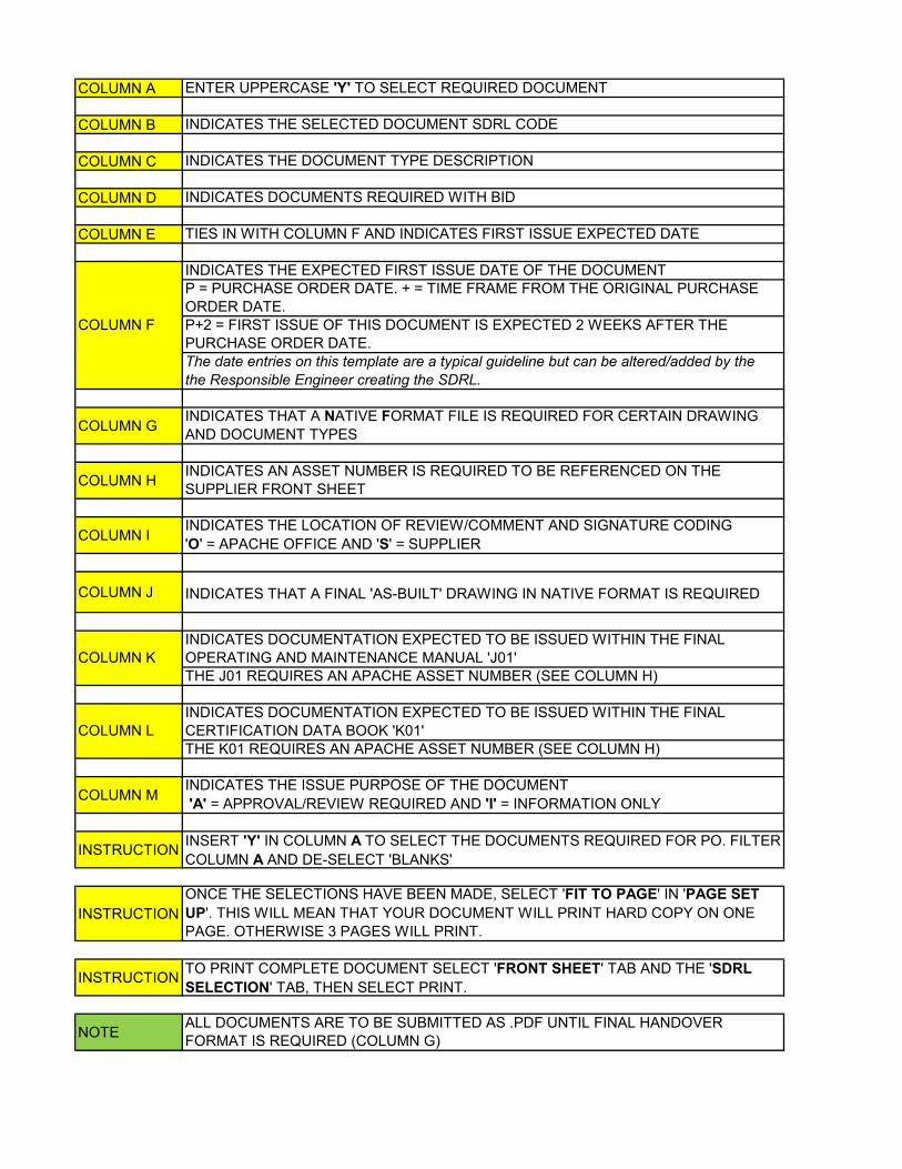
COLUMN A ENTER UPPERCASE 'Y' TO SELECT REQUIRED DOCUMENT
COLUMN B INDICATES THE SELECTED DOCUMENT SDRL CODE
COLUMN C INDICATES THE DOCUMENT TYPE DESCRIPTION
COLUMN D INDICATES DOCUMENTS REQUIRED WITH BID
COLUMN E TIES IN WITH COLUMN F AND INDICATES FIRST ISSUE EXPECTED DATE
INDICATES THE EXPECTED FIRST ISSUE DATE OF THE DOCUMENTP = PURCHASE ORDER DATE. + = TIME FRAME FROM THE ORIGINAL PURCHASE ORDER DATE.P+2 = FIRST ISSUE OF THIS DOCUMENT IS EXPECTED 2 WEEKS AFTER THE PURCHASE ORDER DATE.The date entries on this template are a typical guideline but can be altered/added by the the Responsible Engineer creating the SDRL.
COLUMN G INDICATES THAT A NATIVE FORMAT FILE IS REQUIRED FOR CERTAIN DRAWING AND DOCUMENT TYPES
COLUMN H INDICATES AN ASSET NUMBER IS REQUIRED TO BE REFERENCED ON THE SUPPLIER FRONT SHEET
COLUMN IINDICATES THE LOCATION OF REVIEW/COMMENT AND SIGNATURE CODING 'O' = APACHE OFFICE AND 'S' = SUPPLIER
COLUMN J INDICATES THAT A FINAL 'AS-BUILT' DRAWING IN NATIVE FORMAT IS REQUIRED
INDICATES DOCUMENTATION EXPECTED TO BE ISSUED WITHIN THE FINAL OPERATING AND MAINTENANCE MANUAL 'J01'THE J01 REQUIRES AN APACHE ASSET NUMBER (SEE COLUMN H)
INDICATES DOCUMENTATION EXPECTED TO BE ISSUED WITHIN THE FINAL CERTIFICATION DATA BOOK 'K01'THE K01 REQUIRES AN APACHE ASSET NUMBER (SEE COLUMN H)
COLUMN MINDICATES THE ISSUE PURPOSE OF THE DOCUMENT 'A' = APPROVAL/REVIEW REQUIRED AND 'I' = INFORMATION ONLY
INSTRUCTION INSERT 'Y' IN COLUMN A TO SELECT THE DOCUMENTS REQUIRED FOR PO. FILTER COLUMN A AND DE-SELECT 'BLANKS'
INSTRUCTIONONCE THE SELECTIONS HAVE BEEN MADE, SELECT 'FIT TO PAGE' IN 'PAGE SET UP'. THIS WILL MEAN THAT YOUR DOCUMENT WILL PRINT HARD COPY ON ONE PAGE. OTHERWISE 3 PAGES WILL PRINT.
INSTRUCTION TO PRINT COMPLETE DOCUMENT SELECT 'FRONT SHEET' TAB AND THE 'SDRL SELECTION' TAB, THEN SELECT PRINT.
NOTE ALL DOCUMENTS ARE TO BE SUBMITTED AS .PDF UNTIL FINAL HANDOVER FORMAT IS REQUIRED (COLUMN G)
COLUMN F
COLUMN L
COLUMN K

CODE DOCUMENT FORMAT PURPOSE INFORMATION TO BE SHOWN ON DOCUMENT ADDITIONAL INFO
A - CONTROL DOCUMENTSA01 Supplier’s Document Register (SDR) A3 native/excel version,
purchasers formatControl document • Initial issue by completion of Purchaser's format. Updates by mark-up of Purchaser's computerised
register.• Listing by category and title of all Suppliers’ documents to be issued per SDRL.• Date of first submission of each document to Purchaser.• Listing to contain both Purchaser's and Supplier's document numbers.• Refer to Purchaser's specification 'Drawing and Data Requirements - Instructions to Suppliers' included in the purchase order documentation.
WHERE PURCHASE ORDER REQUIRES THE ISSUE OF A MONTHLY REPORT THIS SCHEDULE SHALL BE INCLUDED UNDER DATA CODE A03 AFTER FIRST SUBMISSION.
A02 Production Schedule Bar Chart (A3 size maximum)
Control document • Schedule to barchart form, showing design, manufacture, inspection, testing and delivery of all equipment, materials and components to be delivered by Supplier and his sub-suppliers.• Earliest and latest completion dates shall be entered alongside each activity with float indicated.• Once agreed with Purchaser, the "planned" dates shall not change without prior approval by purchaser.• Progress to date shall be clearly shown against each activity.• Procurement and delivery of sub-supplier items with names and references to be included.• Summary schedule of issue dates required for all documents in Data Code A01 above grouped by prime category, in bar chart format to show relationship with the Fabrication/Production Schedule.• Schedule to show calendar dates.
WHERE PURCHASE ORDER REQUIRES THE ISSUE OF A MONTHLY REPORT THIS DOCUMENT SHALL BE INCLUDED UNDER DATA CODE A03 AFTER FIRST SUBMISSION.
A03 Progress Report (Weekly / Monthly) A4 Document Control document • Reports to be submitted on the Friday of each week giving: • activities completed this week and % complete; • activities planned for the next week; • any problems encountered, with corrective actions proposed; • identification of areas in which Purchaser is delaying Supplier's progress; • confirmation that contracted delivery date(s) will be maintained;• Monthly report to be submitted three working days after the last Friday in each calendar month;• Report to contain the following information as a minimum:- a) Narrative explaining salient features of work carried out during the month, problems encountered of both an engineering and programme nature, steps being taken to overcome them, and confirmation that contracted delivery date(s) will be achieved. b) Running log of all commercial changes or requests made (whether or not approved by Purchaser) together with status. c) Running log of all design concessions requested by Supplier (whether or not approved by Purchaser) together with current status. d) Updated fabrication/production schedule 'front-lined' to shown actual progress at cut-off (Ref Data Code A02). e) Updated sub-order schedule indicating all sub-orders to be placed by Supplier (Ref Data Code A04). f) Updated Supplier Document Schedule showing status of all drawings to be produced against the order (Ref Data Code A01). g) If purchase order is subject to CA appraisal prior to delivery, certification status report identifying documentation submitted to and approvals received
A04 Sub Vendor List A4 listing Control document • Schedule shall show all sub-orders to be placed by Supplier. Against each entry Supplier shall indicate anticipated award date and the latest data by which sub-order must be placed to meet the overall schedule. Supplier shall submit un-priced copies of sub-orders at the time of order placement.
WHERE PURCHASE ORDER REQUIRES THE ISSUE OF A MONTHLY REPORT THIS SCHEDULE TO BE INCLUDED UNDER DATA CODE A03 AFTER FIRST SUBMISSION
A05 Table of Contents J01 A4 Document Maintenance The index shall contain sufficient information to facilitate ease of accessibility to all sections contained within the manual. Each section shall be systematically compiled.Read in conjunction with MM-P-G-00-GG-018 Instruction to Suppliers – Drawing and Data Requirements
SUPPLIER DOCUMENT REQUIREMENTS LISTING (SDRL) - LONG DESCRIPTION

CODE DOCUMENT FORMAT PURPOSE INFORMATION TO BE SHOWN ON DOCUMENT ADDITIONAL INFO
SUPPLIER DOCUMENT REQUIREMENTS LISTING (SDRL) - LONG DESCRIPTION
A06 Table of Contents K01 A4 Document Certification The index shall contain sufficient information to facilitate ease of accessibility to all sections contained within the manual. Each section shall be systematically compiled.Read in conjunction with MM-P-G-00-GG-018 Instruction to Suppliers – Drawing and Data Requirements
A99 Miscellaneous Control Documents As described in the procurement documents and on SDRL.B - GENERAL ARRANGEMENT DRAWINGSB01 General Arrangement Drawings Maximum size A1.
Scale drawingDesign review and interface liaison
• Envelope and dimensions relative to unit datum.• Access, withdrawal and lay-down requirements for maintenance to be shown.• Location and numbering of all piping and tubing terminations for Purchaser connection to process and utilities, including size, rating and type.• Location of all skid edge junction boxes requiring Purchaser connections.• Identification and location of all major on skid components with Purchaser's tag numbers added.• Where a package consists of more than one skid, separate drawings shall be provided for each skid.• Overall weights and maintenance weights for major components.• Spreader beam, lifting points and C of G to be shown.• Where appropriate, an equipment list is also to be submitted.
B02 Acceptable Nozzle Load A4 Document Design review and interface liaison
Drawing to indicate acceptable loads, forces and moments on flanges to which Purchaser connects, together with loads during normal and maximum operating conditions - if not covered by applicable specifications. Calculations to be included.
B03 Interface and Connection Schedule A4 listing Design review and interface liaison
• Listing by number of all Supplier termination points, including electrical and instrument cable terminations and all junction boxes cross referenced to the relevant drawings.• Size, rating and specification of all piping and tubing termination points requiring purchaser connection.• Identification of corresponding connection point on another skid or system to which each point shall be connected.• Identification of fluids at each connection point including pressure and temperature conditions. For each vent and drain, fluids under normal and abnormal operating conditions shall be stated, and system to which each must be connected (i.e., Purchaser's vent or drain - safe, open or closed).• This document shall always be submitted together with Data Code B01 - General Arrangement Drawings.
B04 Foundation Loading Diagram & Support Details Maximum size A1. Scale drawing
Design review and interface liaison
• Floor fixing details.• Including all static and dynamic forces or movements acting on foundations or other load bearing supports during start-up, shut-down, normal and maximum operation conditions and test conditions (e.g.. motor/generator short circuit).• Also including Supplier's recommended anchor bolt details with sizes and grades and locations (including tolerances) relative to equipment centre lines in all three planes, also recommended lengths and pre-tensioning.• Anchor bolt details show chock block and shimming arrangements.• Temporary fixing details for barge transportation to be shown.• For equipment which is welded, skirt weld preparation is to be detailed.• Operating frequencies for vibrating equipment.• Drawing may be combined with Data Code B01 - General Arrangement Drawings.
B05 Base Plate Details Maximum size A1. Scale drawing
Design review and interface liaison
Size, rating and specification of base plate to ensure purchaser requirments are met.
B06 Lifting Equipment General Arrangements Maximum size A1. Scale drawing
Design review and interface liaison
Where a package consists of more than one skid, separate lifting arrangement drawings shall be provided for each skid.• Overall weights and maintenance weights for major components.• Spreader beam, lifting points and C of G to be shown.• Where appropriate, an equipment list is also to be submitted.
B99 Miscellaneous Arrangements As described in the procurement documents and on SDRL.
C - SYSTEM DIAGRAMS & DATA SHEETS

CODE DOCUMENT FORMAT PURPOSE INFORMATION TO BE SHOWN ON DOCUMENT ADDITIONAL INFO
SUPPLIER DOCUMENT REQUIREMENTS LISTING (SDRL) - LONG DESCRIPTION
C01 Piping and Instrument Diagrams Maximum size A1. Scale drawing
Design review and interface liaison
• P&ID's shall be drawn by Supplier using standard symbols provided on Purchaser's legend sheets, for all hydrocarbon and utility systems including HVAC flow diagrams.• P&ID's are to show at least the following, as applicable:• Revision number.• Drawing title.• Specific notes.• Equipment and spares.• Equipment names and numbers.• Equipment internals and externals, consistent with data sheet.• Insulation and trace heating requirements.• Venting and Draining requirements.• Relief requirements - PSV's location tag numbers and sizes.• PSV interlock valves and interlocking sequence.• Positive Isolation requirements.• Block and check valves, with type identified.• Valves and actuators and solenoids. Failure mode to be stated.• Nozzles of vessels, sizes, manways and other inspection provisions.• Slope of vessels.• Levels in vessels, NLL, LSL, LSH, LSLL, LSHH, etc.• Elevations of major equipment.• Process and utility flowlines with directional arrows.
C02 HVAC Schematic & Flow Diagrams Maximum size A1. Scale drawing
Design review and interface liaison
• Unless agreed otherwise, schematics and flow diagrams shall be drawn by Supplier using standard symbols provided on purchaser’s legend sheet.• Schematic and flow diagrams shall show at least the following as applicable: • Equipment • Ductwork • Instrumentation • Controls • Switches • Equipment Identification etc.
C03 Single Line Electrical Distribution Diagrams Maximum size A1. Scale drawing
Design review and interface liaison
• Representation of electrical power, and/or control circuits, electrical major components and their function or instrument control circuits, defining the relationships, to include (as appropriate): • Control systems. • Consumer rating. • Switchgear/control gear ratings. • Busbar ratings. • Equipment descriptions and tag numbers. • Protection devices.
C04 Bill of Materials A4 listing Design review • Each tagged item on the P&ID (SDRL Code C01) shall be identified and the following information shall be given (as appropriate): • Purchaser's tag number of Supplier's tag number (as applicable). • Service description. • Rating or range of operation. • Materials of construction. • Signal output. • Manufacturer and model number. • Contacts for switches. • Shipped loose items required for offshore installation and assembly shall clearly highlighted.• This document shall always be submitted together with drawing/P&ID/ HVAC flow diagrams to which it refers.
C05 Instrument / Telecoms System Schematic Diagram Maximum size A1. Scale drawing
Design review and interface liaison
All main components and their functional relationship for major control systems (including computer, supervisory, telemetry and communications system) shall be identified on schematic diagrams.
C06 Utility Schedule A4 listing Design review and interface liaison
Schedule to indicate types, quantities, pressure, temperature, voltage, KW, KVA, of all utilities required to start and operate the equipment under start-up normal operation and shutdown conditions.

CODE DOCUMENT FORMAT PURPOSE INFORMATION TO BE SHOWN ON DOCUMENT ADDITIONAL INFO
SUPPLIER DOCUMENT REQUIREMENTS LISTING (SDRL) - LONG DESCRIPTION
C07 Weight Data Sheets Purchaser's A4 sheets completed by Supplier
Design review and interface liaison
• Supplier shall complete weight data sheets for each separately installed item of equipment or skid in accordance with weight data and instructions. Information shall be submitted for each design change affecting weight data and at the following stages during the contract. • with enquiry • 6 weeks after order • where there is any change to the weight identified by Supplier • as weighed, endorsed as such by Purchaser • The following information shall be updated: empty (dry), operating, test (full), shipping weight, C of G.• Heaviest lift during maintenance to be defined.
C08 Equipment Data Sheets Purchaser's A4 sheets completed by Supplier
Design review Where Equipment Data Sheets are issued by Purchaser as part of purchase order, Supplier to fully complete. Data sheets are to be completed for each and every item.
C09 Instrument Data Sheets Purchaser's A4 sheets completed by Supplier
Design review Where Instrument Data Sheets are issued by Purchaser as part of purchase order, Supplier to fully complete. Data sheets are to be completed for each and every item.
C10 Electrical Data Sheets Purchaser's A4 sheets completed by Supplier
Design review Where Electrical Data Sheets are issued by Purchaser as part of purchase order, Supplier to fully complete. Data sheets are to be completed for each and every item.
C11 Schedule of Electrical Equipment in Hazardous Area A4 Listing Certification • All equipment and electrically operated instrumentation equipment to be listed in a tabular form with information presented under the following column headings: • Equipment type i.e. “Junction Box”, “Motor”, and “Pressure Transmitter”. Etc • Tag Number(s) • Quantity fitted (only for identical items fitted in same Zone. All other equipment must be listed individually) • Manufacturer • Manufacturer’s Type Number • Zone in which fitted i.e. Category 1, 2 or 3, or Safe area • Approval Body e.g. KEMA, ITS,SIRA etc. • Type of protection e.g. Flameproof, Increased Safety, and Intrinsically Safe etc. • Type of protection code e.g. EExd: EExe, EExia: etc. • Apparatus Group (sometimes call “Gas Group”) e.g. IIA: IIB: IIC. • Temperature Classifications e.g. T3, T6 etc. • Hazardous Area Certificate Number • Date of expiry of current NOTIFIED BODY LICENCE (not certificate) • Standard to which the equipment is certified e.g. BS5501 Part 9 • Entry Protection i.e. the IP rating e.g. IP56, IP67 etc.
C12 Electrical/Electronic/Pneumatic/Hydraulic Schematics Maximum size A1. Scale drawing
Design review and interface liaison
• Diagrams shall indicate the schematic arrangement of all component parts. The format shall be such that an understanding of the function shall be readily gained with accompanying notes, if needed. Relays shall be shown in a de-energised state, with their contacts open or closed accordingly.• Interface terminals shall be uniquely identified by symbol, type and number and their physical location identified.

CODE DOCUMENT FORMAT PURPOSE INFORMATION TO BE SHOWN ON DOCUMENT ADDITIONAL INFO
SUPPLIER DOCUMENT REQUIREMENTS LISTING (SDRL) - LONG DESCRIPTION
C13 Detailed Description of Operation A4 Document Operating Review • This document shall be a detailed written description of Suppliers primary design interpretation of Purchaser’s requirements giving principles of equipment function and defining of all aspects of the operation of the equipment supplied. It shall also include block logic and detailed diagrams input/output circuitry as follows:• Simplified block logic diagrams shall relate to the system by project tag number• Start-up, shutdown abnormal operating condition and special maintenance operations shall be covered.• Reference shall be made to P&IDs and other documents submitted to the Purchasers tag numbers.• Input, output, permissive signals, including internal logic signals required to accomplish start-up, platform equipment monitoring and alarm, shut-down etc. shall be described.• Display of information, operator and maintenance interface and access to the package control system shall be described.• Listing of pre-alarm and shut-down alarm trip requirements (local and CCR) and the failure mode of all valves and equipment must be clearly indicated.• Control block diagrams shall clearly show switch room equipment, control room equipment/CCR equipment and types of signal to and from interface information clearly defined.• Typical circuitry for all input and output signals shall be produced in sketches and narrative form.• Communication / data transfer arrangements shall be fully defined showing hardware standards and software protocols.• Manual and automatic testing of the system shall be clearly detailed.• Software programme development, test and documentation facilities and routines shall be fully detailed.
C14 Process Flow Diagrams and Heat and Mass Balance A3 detailed drawings Design review • Diagrams shall be provided for all hydrocarbon and utilities systems. Diagrams shall be drawn using Purchaser symbology, and shall indicate major control functions.• Each stream shall be clearly labelled with a tag number. PFD will indicate the duty performed by all items of equipment for example, power requirements and ate of heat transfer, etc. Accompanying the PFD shall be a Heat and Mass Balance Sheet relating to the stream tag numbers on the PFD.
C15 Electrical Power Supply Requirements Data Sheets Purchaser's A4 sheets completed by Supplier
Design review Where Electrical Power Supply Requirements Data Sheets are issued by Purchaser as part of purchase order, Supplier to fully complete. Data sheets are to be completed for each and every item.
C16 Enclosure Ventilation Requirements Data Sheets Purchaser's A4 sheets completed by Supplier
Design review Where Enclosure Ventilation Requirements Data Sheets are issued by Purchaser as part of purchase order, Supplier to fully complete. Data sheets are to be completed for each and every item.
C17 Cause & Effect Drawings Purchaser's A3 sheets completed by Supplier
Design review These shall be in accordance with API RP14C to indicate clearly and precisely the shutdown requirements on the standard format sheet with defined convention. Individual C&E charts to be produced for each process unit. All auto start/changeover, etc, of pumps etc, to be clearly defined with location of field devices.
C18 Detailed Parts List A4 Document Design review Supplier shall prepare a detailed parts list
C99 Miscellaneous System Diagrams and Data Sheets As described in the procurement documents and on SDRL.
D - DETAIL DRAWINGSD01 Cross Section / Exploded View Drawings with Parts List Maximum size A1.
Scale drawingDesign review • Scale drawings of component parts shall be shown in cross section or, if required, by exploded view
representative where the various parts of the assembly are separated, but in proper position relative to each other. All parts to be identified by the parts list, which shall give full details of: • Material of Construction • Thickness • Manufacturer and references No.
D02 Mechanical Seal Drawings Maximum size A1. Scale drawing
Design review • Dimensions including clearances.• Parts list, defining materials,• Identification of fluid connection points.• Seal system description (if required).• Description of operation (if required).• Piping system indicating all components and materials.
D03 Shaft Alignment Drawings Maximum size A1. Scale drawing
Design review Scale drawings showing design/actual alignment with thermal growths and tolerances both angular and displacement together with alignment procedures.
CODE DOCUMENT FORMAT PURPOSE INFORMATION TO BE SHOWN ON DOCUMENT ADDITIONAL INFO
SUPPLIER DOCUMENT REQUIREMENTS LISTING (SDRL) - LONG DESCRIPTION
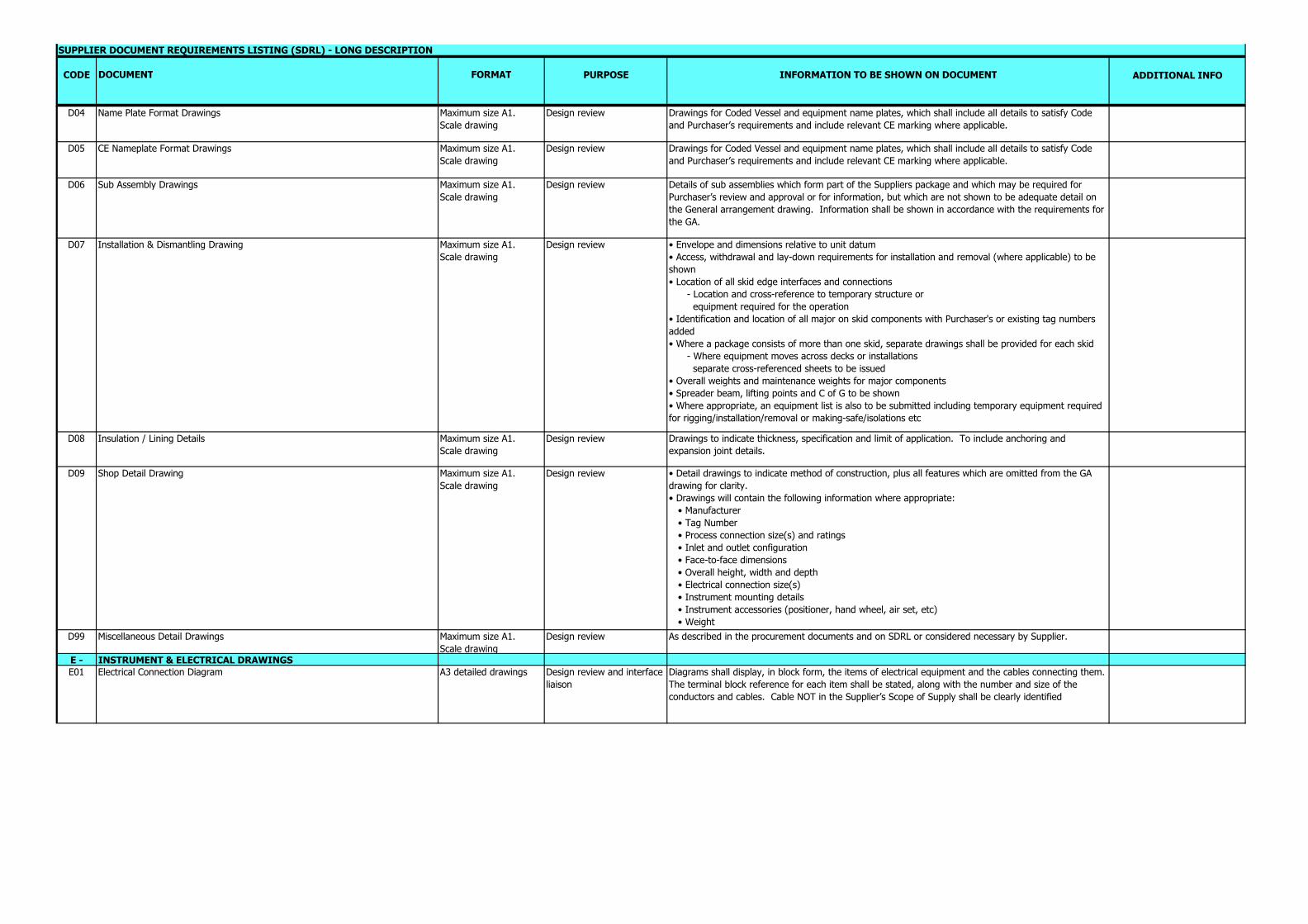
D04 Name Plate Format Drawings Maximum size A1. Scale drawing
Design review Drawings for Coded Vessel and equipment name plates, which shall include all details to satisfy Code and Purchaser’s requirements and include relevant CE marking where applicable.
D05 CE Nameplate Format Drawings Maximum size A1. Scale drawing
Design review Drawings for Coded Vessel and equipment name plates, which shall include all details to satisfy Code and Purchaser’s requirements and include relevant CE marking where applicable.
D06 Sub Assembly Drawings Maximum size A1. Scale drawing
Design review Details of sub assemblies which form part of the Suppliers package and which may be required for Purchaser’s review and approval or for information, but which are not shown to be adequate detail on the General arrangement drawing. Information shall be shown in accordance with the requirements for the GA.
D07 Installation & Dismantling Drawing Maximum size A1. Scale drawing
Design review • Envelope and dimensions relative to unit datum• Access, withdrawal and lay-down requirements for installation and removal (where applicable) to be shown• Location of all skid edge interfaces and connections - Location and cross-reference to temporary structure or equipment required for the operation• Identification and location of all major on skid components with Purchaser's or existing tag numbers added• Where a package consists of more than one skid, separate drawings shall be provided for each skid - Where equipment moves across decks or installations separate cross-referenced sheets to be issued• Overall weights and maintenance weights for major components• Spreader beam, lifting points and C of G to be shown• Where appropriate, an equipment list is also to be submitted including temporary equipment required for rigging/installation/removal or making-safe/isolations etc
D08 Insulation / Lining Details Maximum size A1. Scale drawing
Design review Drawings to indicate thickness, specification and limit of application. To include anchoring and expansion joint details.
D09 Shop Detail Drawing Maximum size A1. Scale drawing
Design review • Detail drawings to indicate method of construction, plus all features which are omitted from the GA drawing for clarity.• Drawings will contain the following information where appropriate: • Manufacturer • Tag Number • Process connection size(s) and ratings • Inlet and outlet configuration • Face-to-face dimensions • Overall height, width and depth • Electrical connection size(s) • Instrument mounting details • Instrument accessories (positioner, hand wheel, air set, etc) • Weight
D99 Miscellaneous Detail Drawings Maximum size A1. Scale drawing
Design review As described in the procurement documents and on SDRL or considered necessary by Supplier.
E - INSTRUMENT & ELECTRICAL DRAWINGSE01 Electrical Connection Diagram A3 detailed drawings Design review and interface
liaisonDiagrams shall display, in block form, the items of electrical equipment and the cables connecting them. The terminal block reference for each item shall be stated, along with the number and size of the conductors and cables. Cable NOT in the Supplier’s Scope of Supply shall be clearly identified
CODE DOCUMENT FORMAT PURPOSE INFORMATION TO BE SHOWN ON DOCUMENT ADDITIONAL INFO
SUPPLIER DOCUMENT REQUIREMENTS LISTING (SDRL) - LONG DESCRIPTION
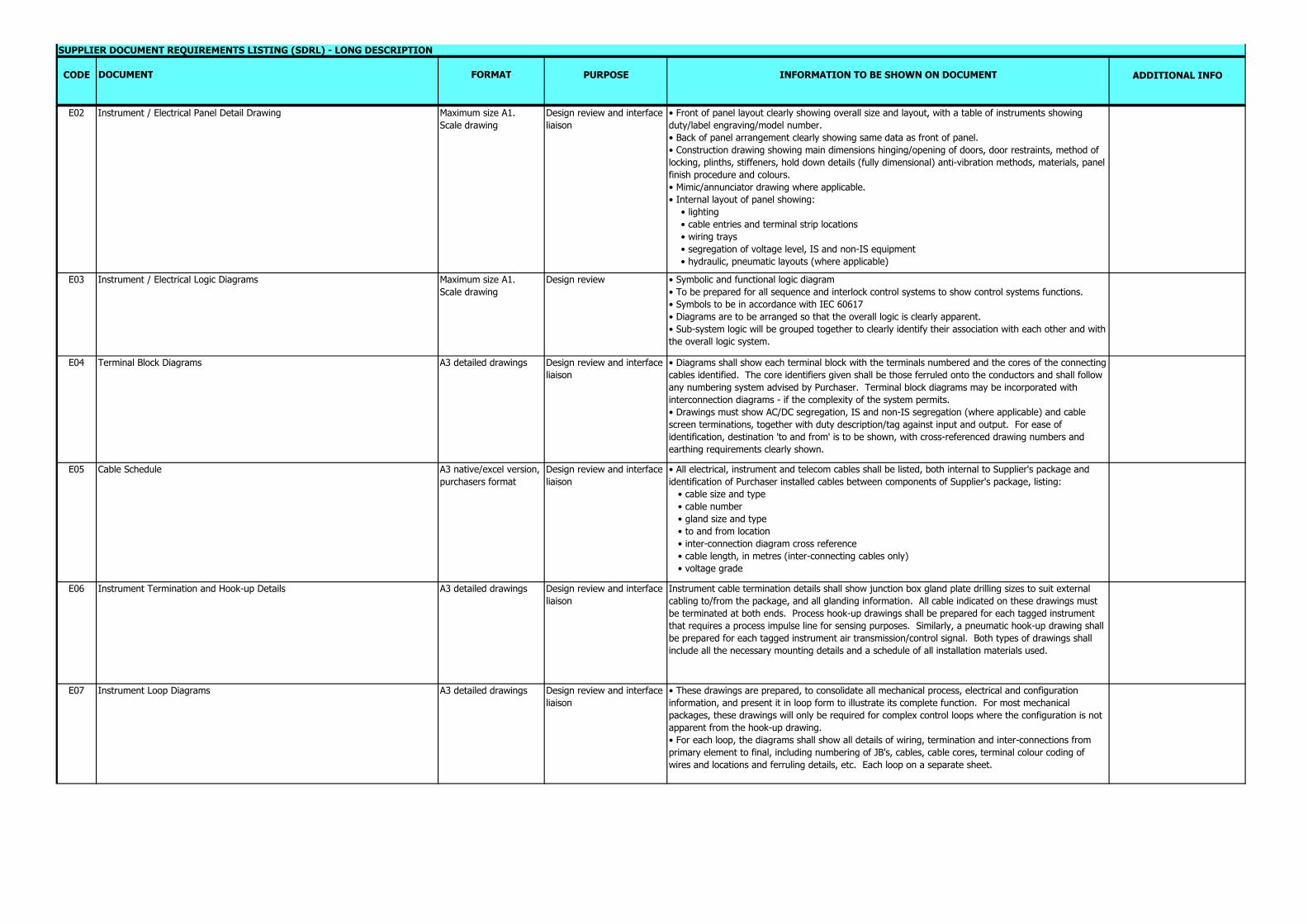
E02 Instrument / Electrical Panel Detail Drawing Maximum size A1. Scale drawing
Design review and interface liaison
• Front of panel layout clearly showing overall size and layout, with a table of instruments showing duty/label engraving/model number.• Back of panel arrangement clearly showing same data as front of panel.• Construction drawing showing main dimensions hinging/opening of doors, door restraints, method of locking, plinths, stiffeners, hold down details (fully dimensional) anti-vibration methods, materials, panel finish procedure and colours.• Mimic/annunciator drawing where applicable.• Internal layout of panel showing: • lighting • cable entries and terminal strip locations • wiring trays • segregation of voltage level, IS and non-IS equipment • hydraulic, pneumatic layouts (where applicable)
E03 Instrument / Electrical Logic Diagrams Maximum size A1. Scale drawing
Design review • Symbolic and functional logic diagram• To be prepared for all sequence and interlock control systems to show control systems functions.• Symbols to be in accordance with IEC 60617• Diagrams are to be arranged so that the overall logic is clearly apparent.• Sub-system logic will be grouped together to clearly identify their association with each other and with the overall logic system.
E04 Terminal Block Diagrams A3 detailed drawings Design review and interface liaison
• Diagrams shall show each terminal block with the terminals numbered and the cores of the connecting cables identified. The core identifiers given shall be those ferruled onto the conductors and shall follow any numbering system advised by Purchaser. Terminal block diagrams may be incorporated with interconnection diagrams - if the complexity of the system permits.• Drawings must show AC/DC segregation, IS and non-IS segregation (where applicable) and cable screen terminations, together with duty description/tag against input and output. For ease of identification, destination 'to and from' is to be shown, with cross-referenced drawing numbers and earthing requirements clearly shown.
E05 Cable Schedule A3 native/excel version, purchasers format
Design review and interface liaison
• All electrical, instrument and telecom cables shall be listed, both internal to Supplier's package and identification of Purchaser installed cables between components of Supplier's package, listing: • cable size and type • cable number • gland size and type • to and from location • inter-connection diagram cross reference • cable length, in metres (inter-connecting cables only) • voltage grade
E06 Instrument Termination and Hook-up Details A3 detailed drawings Design review and interface liaison
Instrument cable termination details shall show junction box gland plate drilling sizes to suit external cabling to/from the package, and all glanding information. All cable indicated on these drawings must be terminated at both ends. Process hook-up drawings shall be prepared for each tagged instrument that requires a process impulse line for sensing purposes. Similarly, a pneumatic hook-up drawing shall be prepared for each tagged instrument air transmission/control signal. Both types of drawings shall include all the necessary mounting details and a schedule of all installation materials used.
E07 Instrument Loop Diagrams A3 detailed drawings Design review and interface liaison
• These drawings are prepared, to consolidate all mechanical process, electrical and configuration information, and present it in loop form to illustrate its complete function. For most mechanical packages, these drawings will only be required for complex control loops where the configuration is not apparent from the hook-up drawing.• For each loop, the diagrams shall show all details of wiring, termination and inter-connections from primary element to final, including numbering of JB's, cables, cable cores, terminal colour coding of wires and locations and ferruling details, etc. Each loop on a separate sheet.

CODE DOCUMENT FORMAT PURPOSE INFORMATION TO BE SHOWN ON DOCUMENT ADDITIONAL INFO
SUPPLIER DOCUMENT REQUIREMENTS LISTING (SDRL) - LONG DESCRIPTION
E08 A3 native/excel version, purchasers format
Installation, commissioning and maintenance
• The following minimum information must be presented in a format advised by the Purchaser: • Tag number (in alpha-numeric sequence). • Purchasers Works Identification Number (WI Number). • Instrument description (pressure switch, control valve, level gauge, etc). • Service description (e.g. pump P3102 discharge, etc). • Location of line (size/number/spec) • P&ID number. • Data sheet number. • Hook-up drawing reference.
E09 Specifications DO NOT USE - USE F02 A4 Document Design review Use F02E10 Trace Heating Drawings Maximum size A1.
Scale drawingDesign review and interface liaison
Documentation including layout drawings, isometrics, distribution drawings and Trace Heating Distribution Board Schedules.
E11 Instrument / Electrical Layout Drawings Maximum size A1. Scale drawing
Design review and interface liaison
Layout drawings will show the location and elevation of all instruments, control valves, control panels etc, and Purchaser free issued equipment where applicable. In addition, the drawing will show the routing of all instrument air distribution, pneumatic tubing, signal/power supply cables, and the location of all instrument junction boxes. Layout drawings will also be required to show fire detection instrumentation.
E99 Miscellaneous Instrument/Electrical Drawings As described in the procurement document and on SDRL.
F - CALCULATIONS & PERFORMANCE DATAF01 Reliability / Availability Data & Calculations A4 Document Design review • Known reliability of equipment on a package basis, ideally expressed as MTBF (Mean Time Between
Failures) or otherwise presented as required by the Purchaser's Specifications or Data Sheets.• Known reliability of key constituent components the basis of this data to be clearly defined.• Estimate repair time (assuming immediate availability of spares). Fully detailed calculations to demonstrate that the equipment shall meet Purchaser's required availability as included in Purchaser's Specifications
F02 Functional and Detailed Design Specifications A4 Document Design review • Pre-development documentation which translates all notes, concepts, and scope into a complete requirements document. • At a minimum, the FDS will contain an organized list of requirements that can be used for development, testing, and client sign-off.
F03 Anti Surge Valve Sizing Calculations A4 Document Design review and interface liaison
System calculations to substantiate valve sizing selection, and noise data. Information to be provided as per Data Code F14 below.
Combined F03
F03 Bearing Life Calculations A4 Document Design review Calculations for Rolling Element bearings shall determine anticipated B10 life with bearing identification in accordance with ANSI B3.15 or B3.16 for radial, axial or combined loading, considering methods of lubrication, dimensions, and load variation determined from performance envelope.
Combined F03
F03 Coupling Selection Calculations A4 Document Design review To show speed range, torque, power and lock-up axial stiffness, torsional stiffness, service factors, etc, to substantiate coupling selection.
Combined F03
F03 ESD Valve Calculations A4 Document Design review Flow capacity calculations break out, running and reseating torque figures for valve versus actuator torque figures at minimum supply pressure.
Combined F03
F03 Exchanger Thermal Rating Calculations A4 Document Design review Calculations to demonstrate thermal ratings of heat exchangers. Combined F03
F03 Fatigue Calculations (Riser System) A4 Document Design review A fatigue analysis must be performed of the riser systems to guarantee the fatigue life of the riser meets the field life. The analysis must be made in conjunction with the environmental conditions in the field.
Combined F03
F03 Fatigue Calculations (Well Conversion) A4 Document Design review As part of the conversion system detail design for a mudline suspension system a fatigue analysis must be performed to verify the design and to ensure the design working life.
Combined F03
F03 Fiscal Metering System Calculations A4 Document Design review • Calculations required for design purposes include gas systems: - uncertainty calculations, orifice plate calculations, total pressure drop calculations, thermowell vibration calculations, stress analysis.• Liquid System: - Prover sizing, total pressure drop, FCV/RV sizing, thermowell vibration calculations, stress analysis.
Combined F03
CODE DOCUMENT FORMAT PURPOSE INFORMATION TO BE SHOWN ON DOCUMENT ADDITIONAL INFO
SUPPLIER DOCUMENT REQUIREMENTS LISTING (SDRL) - LONG DESCRIPTION
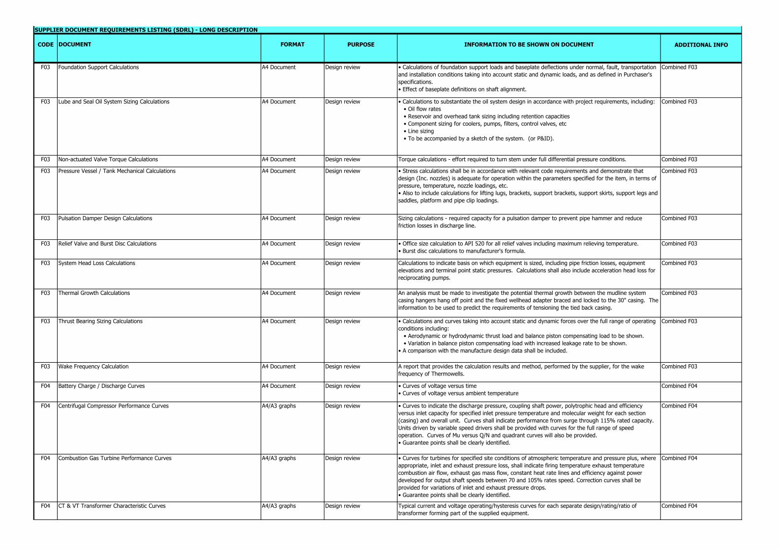
F03 Foundation Support Calculations A4 Document Design review • Calculations of foundation support loads and baseplate deflections under normal, fault, transportation and installation conditions taking into account static and dynamic loads, and as defined in Purchaser's specifications.• Effect of baseplate definitions on shaft alignment.
Combined F03
F03 Lube and Seal Oil System Sizing Calculations A4 Document Design review • Calculations to substantiate the oil system design in accordance with project requirements, including: • Oil flow rates • Reservoir and overhead tank sizing including retention capacities • Component sizing for coolers, pumps, filters, control valves, etc • Line sizing • To be accompanied by a sketch of the system. (or P&ID).
Combined F03
F03 Non-actuated Valve Torque Calculations A4 Document Design review Torque calculations - effort required to turn stem under full differential pressure conditions. Combined F03
F03 Pressure Vessel / Tank Mechanical Calculations A4 Document Design review • Stress calculations shall be in accordance with relevant code requirements and demonstrate that design (Inc. nozzles) is adequate for operation within the parameters specified for the item, in terms of pressure, temperature, nozzle loadings, etc.• Also to include calculations for lifting lugs, brackets, support brackets, support skirts, support legs and saddles, platform and pipe clip loadings.
Combined F03
F03 Pulsation Damper Design Calculations A4 Document Design review Sizing calculations - required capacity for a pulsation damper to prevent pipe hammer and reduce friction losses in discharge line.
Combined F03
F03 Relief Valve and Burst Disc Calculations A4 Document Design review • Office size calculation to API 520 for all relief valves including maximum relieving temperature.• Burst disc calculations to manufacturer's formula.
Combined F03
F03 System Head Loss Calculations A4 Document Design review Calculations to indicate basis on which equipment is sized, including pipe friction losses, equipment elevations and terminal point static pressures. Calculations shall also include acceleration head loss for reciprocating pumps.
Combined F03
F03 Thermal Growth Calculations A4 Document Design review An analysis must be made to investigate the potential thermal growth between the mudline system casing hangers hang off point and the fixed wellhead adapter braced and locked to the 30" casing. The information to be used to predict the requirements of tensioning the tied back casing.
Combined F03
F03 Thrust Bearing Sizing Calculations A4 Document Design review • Calculations and curves taking into account static and dynamic forces over the full range of operating conditions including: • Aerodynamic or hydrodynamic thrust load and balance piston compensating load to be shown. • Variation in balance piston compensating load with increased leakage rate to be shown.• A comparison with the manufacture design data shall be included.
Combined F03
F03 Wake Frequency Calculation A4 Document Design review A report that provides the calculation results and method, performed by the supplier, for the wake frequency of Thermowells.
Combined F03
F04 Battery Charge / Discharge Curves A4 Document Design review • Curves of voltage versus time• Curves of voltage versus ambient temperature
Combined F04
F04 Centrifugal Compressor Performance Curves A4/A3 graphs Design review • Curves to indicate the discharge pressure, coupling shaft power, polytrophic head and efficiency versus inlet capacity for specified inlet pressure temperature and molecular weight for each section (casing) and overall unit. Curves shall indicate performance from surge through 115% rated capacity. Units driven by variable speed drivers shall be provided with curves for the full range of speed operation. Curves of Mu versus Q/N and quadrant curves will also be provided.• Guarantee points shall be clearly identified.
Combined F04
F04 Combustion Gas Turbine Performance Curves A4/A3 graphs Design review • Curves for turbines for specified site conditions of atmospheric temperature and pressure plus, where appropriate, inlet and exhaust pressure loss, shall indicate firing temperature exhaust temperature combustion air flow, exhaust gas mass flow, constant heat rate lines and efficiency against power developed for output shaft speeds between 70 and 105% rates speed. Correction curves shall be provided for variations of inlet and exhaust pressure drops.• Guarantee points shall be clearly identified.
Combined F04
F04 CT & VT Transformer Characteristic Curves A4/A3 graphs Design review Typical current and voltage operating/hysteresis curves for each separate design/rating/ratio of transformer forming part of the supplied equipment.
Combined F04
CODE DOCUMENT FORMAT PURPOSE INFORMATION TO BE SHOWN ON DOCUMENT ADDITIONAL INFO
SUPPLIER DOCUMENT REQUIREMENTS LISTING (SDRL) - LONG DESCRIPTION
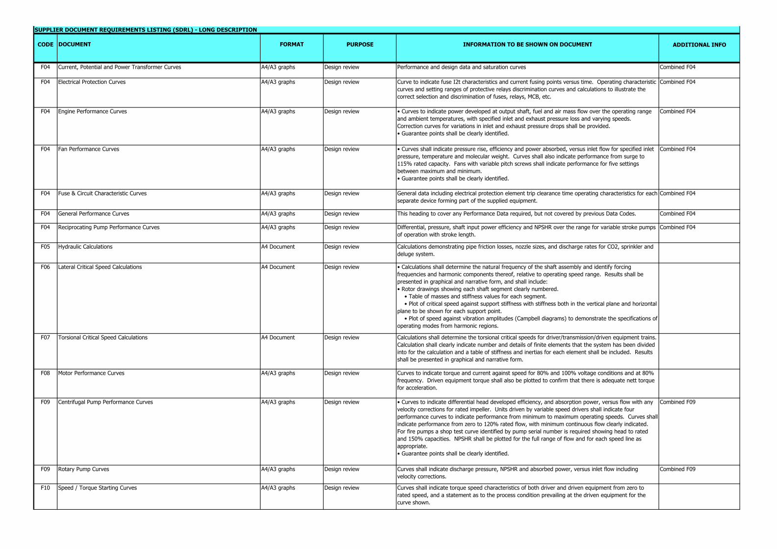
F04 Current, Potential and Power Transformer Curves A4/A3 graphs Design review Performance and design data and saturation curves Combined F04
F04 Electrical Protection Curves A4/A3 graphs Design review Curve to indicate fuse I2t characteristics and current fusing points versus time. Operating characteristic curves and setting ranges of protective relays discrimination curves and calculations to illustrate the correct selection and discrimination of fuses, relays, MCB, etc.
Combined F04
F04 Engine Performance Curves A4/A3 graphs Design review • Curves to indicate power developed at output shaft, fuel and air mass flow over the operating range and ambient temperatures, with specified inlet and exhaust pressure loss and varying speeds. Correction curves for variations in inlet and exhaust pressure drops shall be provided.• Guarantee points shall be clearly identified.
Combined F04
F04 Fan Performance Curves A4/A3 graphs Design review • Curves shall indicate pressure rise, efficiency and power absorbed, versus inlet flow for specified inlet pressure, temperature and molecular weight. Curves shall also indicate performance from surge to 115% rated capacity. Fans with variable pitch screws shall indicate performance for five settings between maximum and minimum.• Guarantee points shall be clearly identified.
Combined F04
F04 Fuse & Circuit Characteristic Curves A4/A3 graphs Design review General data including electrical protection element trip clearance time operating characteristics for each separate device forming part of the supplied equipment.
Combined F04
F04 General Performance Curves A4/A3 graphs Design review This heading to cover any Performance Data required, but not covered by previous Data Codes. Combined F04
F04 Reciprocating Pump Performance Curves A4/A3 graphs Design review Differential, pressure, shaft input power efficiency and NPSHR over the range for variable stroke pumps of operation with stroke length.
Combined F04
F05 Hydraulic Calculations A4 Document Design review Calculations demonstrating pipe friction losses, nozzle sizes, and discharge rates for CO2, sprinkler and deluge system.
F06 Lateral Critical Speed Calculations A4 Document Design review • Calculations shall determine the natural frequency of the shaft assembly and identify forcing frequencies and harmonic components thereof, relative to operating speed range. Results shall be presented in graphical and narrative form, and shall include:• Rotor drawings showing each shaft segment clearly numbered. • Table of masses and stiffness values for each segment. • Plot of critical speed against support stiffness with stiffness both in the vertical plane and horizontal plane to be shown for each support point. • Plot of speed against vibration amplitudes (Campbell diagrams) to demonstrate the specifications of operating modes from harmonic regions.
F07 Torsional Critical Speed Calculations A4 Document Design review Calculations shall determine the torsional critical speeds for driver/transmission/driven equipment trains. Calculation shall clearly indicate number and details of finite elements that the system has been divided into for the calculation and a table of stiffness and inertias for each element shall be included. Results shall be presented in graphical and narrative form.
F08 Motor Performance Curves A4/A3 graphs Design review Curves to indicate torque and current against speed for 80% and 100% voltage conditions and at 80% frequency. Driven equipment torque shall also be plotted to confirm that there is adequate nett torque for acceleration.
F09 Centrifugal Pump Performance Curves A4/A3 graphs Design review • Curves to indicate differential head developed efficiency, and absorption power, versus flow with any velocity corrections for rated impeller. Units driven by variable speed drivers shall indicate four performance curves to indicate performance from minimum to maximum operating speeds. Curves shall indicate performance from zero to 120% rated flow, with minimum continuous flow clearly indicated. For fire pumps a shop test curve identified by pump serial number is required showing head to rated and 150% capacities. NPSHR shall be plotted for the full range of flow and for each speed line as appropriate.• Guarantee points shall be clearly identified.
Combined F09
F09 Rotary Pump Curves A4/A3 graphs Design review Curves shall indicate discharge pressure, NPSHR and absorbed power, versus inlet flow including velocity corrections.
Combined F09
F10 Speed / Torque Starting Curves A4/A3 graphs Design review Curves shall indicate torque speed characteristics of both driver and driven equipment from zero to rated speed, and a statement as to the process condition prevailing at the driven equipment for the curve shown.
CODE DOCUMENT FORMAT PURPOSE INFORMATION TO BE SHOWN ON DOCUMENT ADDITIONAL INFO
SUPPLIER DOCUMENT REQUIREMENTS LISTING (SDRL) - LONG DESCRIPTION
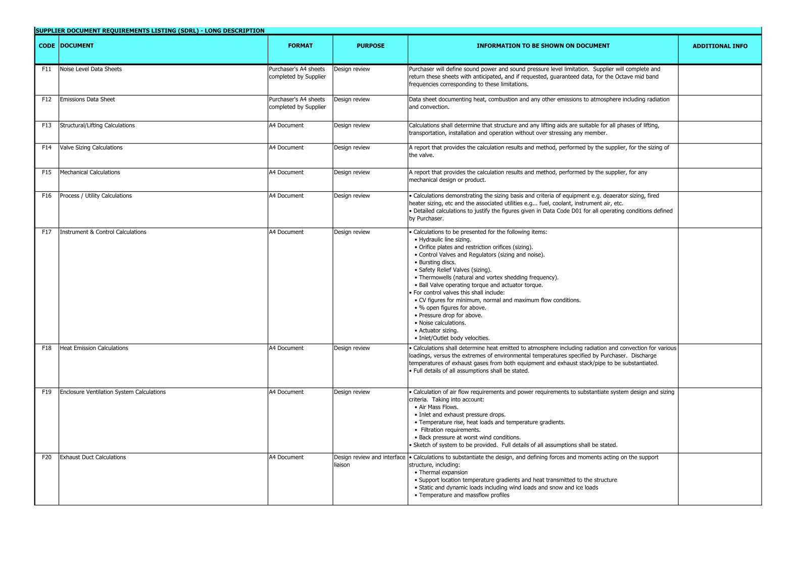
F11 Noise Level Data Sheets Purchaser's A4 sheets completed by Supplier
Design review Purchaser will define sound power and sound pressure level limitation. Supplier will complete and return these sheets with anticipated, and if requested, guaranteed data, for the Octave mid band frequencies corresponding to these limitations.
F12 Emissions Data Sheet Purchaser's A4 sheets completed by Supplier
Design review Data sheet documenting heat, combustion and any other emissions to atmosphere including radiation and convection.
F13 Structural/Lifting Calculations A4 Document Design review Calculations shall determine that structure and any lifting aids are suitable for all phases of lifting, transportation, installation and operation without over stressing any member.
F14 Valve Sizing Calculations A4 Document Design review A report that provides the calculation results and method, performed by the supplier, for the sizing of the valve.
F15 Mechanical Calculations A4 Document Design review A report that provides the calculation results and method, performed by the supplier, for any mechanical design or product.
F16 Process / Utility Calculations A4 Document Design review • Calculations demonstrating the sizing basis and criteria of equipment e.g. deaerator sizing, fired heater sizing, etc and the associated utilities e.g... fuel, coolant, instrument air, etc.• Detailed calculations to justify the figures given in Data Code D01 for all operating conditions defined by Purchaser.
F17 Instrument & Control Calculations A4 Document Design review • Calculations to be presented for the following items: • Hydraulic line sizing. • Orifice plates and restriction orifices (sizing). • Control Valves and Regulators (sizing and noise). • Bursting discs. • Safety Relief Valves (sizing). • Thermowells (natural and vortex shedding frequency). • Ball Valve operating torque and actuator torque.• For control valves this shall include: • CV figures for minimum, normal and maximum flow conditions. • % open figures for above. • Pressure drop for above. • Noise calculations. • Actuator sizing. • Inlet/Outlet body velocities.
F18 Heat Emission Calculations A4 Document Design review • Calculations shall determine heat emitted to atmosphere including radiation and convection for various loadings, versus the extremes of environmental temperatures specified by Purchaser. Discharge temperatures of exhaust gases from both equipment and exhaust stack/pipe to be substantiated.• Full details of all assumptions shall be stated.
F19 Enclosure Ventilation System Calculations A4 Document Design review • Calculation of air flow requirements and power requirements to substantiate system design and sizing criteria. Taking into account: • Air Mass Flows. • Inlet and exhaust pressure drops. • Temperature rise, heat loads and temperature gradients. • Filtration requirements. • Back pressure at worst wind conditions.• Sketch of system to be provided. Full details of all assumptions shall be stated.
F20 Exhaust Duct Calculations A4 Document Design review and interface liaison
• Calculations to substantiate the design, and defining forces and moments acting on the support structure, including: • Thermal expansion • Support location temperature gradients and heat transmitted to the structure • Static and dynamic loads including wind loads and snow and ice loads • Temperature and massflow profiles
CODE DOCUMENT FORMAT PURPOSE INFORMATION TO BE SHOWN ON DOCUMENT ADDITIONAL INFO
SUPPLIER DOCUMENT REQUIREMENTS LISTING (SDRL) - LONG DESCRIPTION
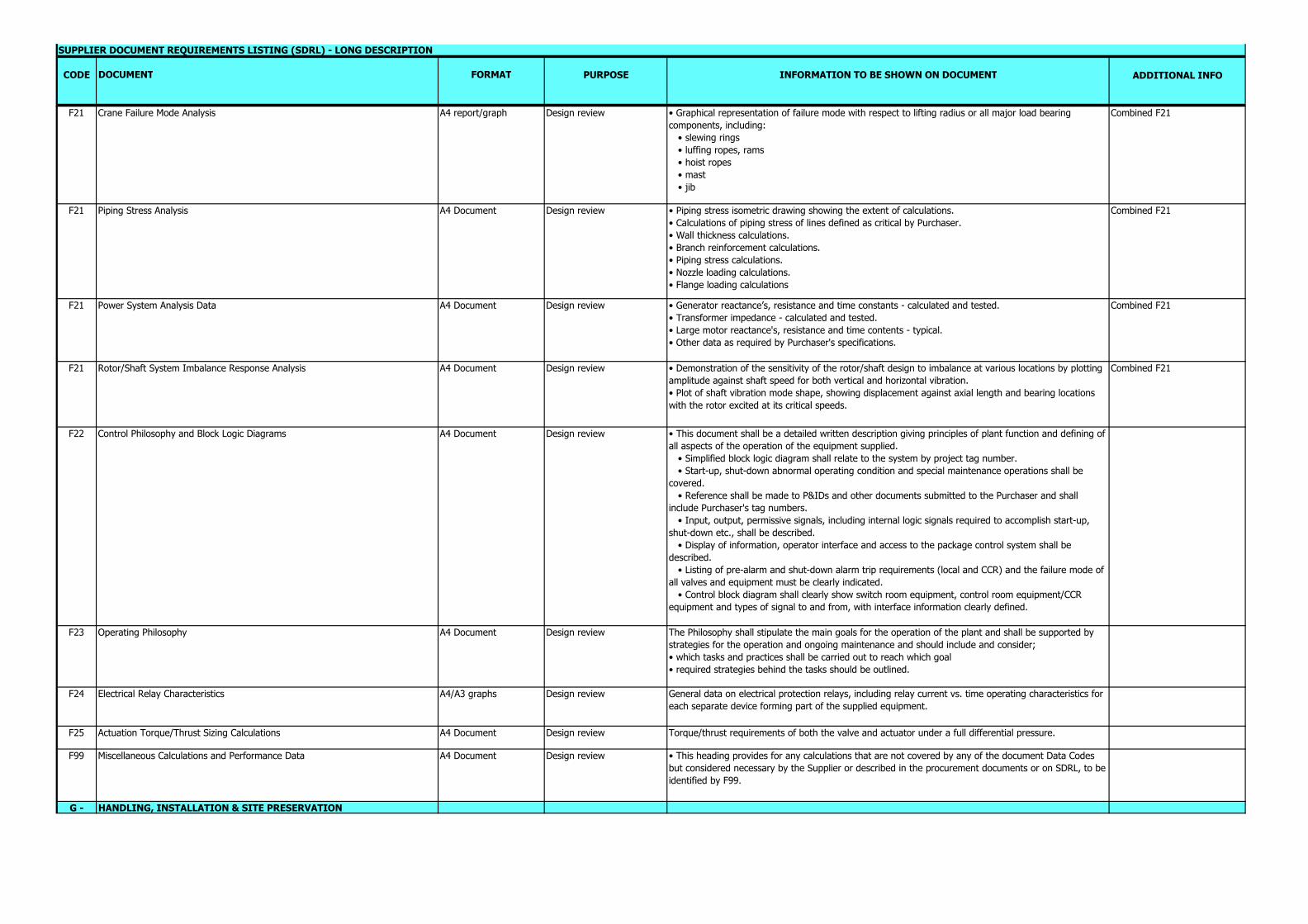
F21 Crane Failure Mode Analysis A4 report/graph Design review • Graphical representation of failure mode with respect to lifting radius or all major load bearing components, including: • slewing rings • luffing ropes, rams • hoist ropes • mast • jib
Combined F21
F21 Piping Stress Analysis A4 Document Design review • Piping stress isometric drawing showing the extent of calculations.• Calculations of piping stress of lines defined as critical by Purchaser.• Wall thickness calculations.• Branch reinforcement calculations.• Piping stress calculations.• Nozzle loading calculations.• Flange loading calculations
Combined F21
F21 Power System Analysis Data A4 Document Design review • Generator reactance’s, resistance and time constants - calculated and tested.• Transformer impedance - calculated and tested.• Large motor reactance's, resistance and time contents - typical.• Other data as required by Purchaser's specifications.
Combined F21
F21 Rotor/Shaft System Imbalance Response Analysis A4 Document Design review • Demonstration of the sensitivity of the rotor/shaft design to imbalance at various locations by plotting amplitude against shaft speed for both vertical and horizontal vibration.• Plot of shaft vibration mode shape, showing displacement against axial length and bearing locations with the rotor excited at its critical speeds.
Combined F21
F22 Control Philosophy and Block Logic Diagrams A4 Document Design review • This document shall be a detailed written description giving principles of plant function and defining of all aspects of the operation of the equipment supplied. • Simplified block logic diagram shall relate to the system by project tag number. • Start-up, shut-down abnormal operating condition and special maintenance operations shall be covered. • Reference shall be made to P&IDs and other documents submitted to the Purchaser and shall include Purchaser's tag numbers. • Input, output, permissive signals, including internal logic signals required to accomplish start-up, shut-down etc., shall be described. • Display of information, operator interface and access to the package control system shall be described. • Listing of pre-alarm and shut-down alarm trip requirements (local and CCR) and the failure mode of all valves and equipment must be clearly indicated. • Control block diagram shall clearly show switch room equipment, control room equipment/CCR equipment and types of signal to and from, with interface information clearly defined.
F23 Operating Philosophy A4 Document Design review The Philosophy shall stipulate the main goals for the operation of the plant and shall be supported by strategies for the operation and ongoing maintenance and should include and consider; • which tasks and practices shall be carried out to reach which goal• required strategies behind the tasks should be outlined.
F24 Electrical Relay Characteristics A4/A3 graphs Design review General data on electrical protection relays, including relay current vs. time operating characteristics for each separate device forming part of the supplied equipment.
F25 Actuation Torque/Thrust Sizing Calculations A4 Document Design review Torque/thrust requirements of both the valve and actuator under a full differential pressure.
F99 Miscellaneous Calculations and Performance Data A4 Document Design review • This heading provides for any calculations that are not covered by any of the document Data Codes but considered necessary by the Supplier or described in the procurement documents or on SDRL, to be identified by F99.
G - HANDLING, INSTALLATION & SITE PRESERVATION

CODE DOCUMENT FORMAT PURPOSE INFORMATION TO BE SHOWN ON DOCUMENT ADDITIONAL INFO
SUPPLIER DOCUMENT REQUIREMENTS LISTING (SDRL) - LONG DESCRIPTION
G01 Erection and Installation Procedure A4 manuals and drawings
Installation • lifting points• lifting weights• shipping break points for panels and switchboard assemblies• erection match markings• fixing points• levelling procedures• alignment procedures• erection fasteners summary list• details of any special unpacking/handling requirements shall be stated
G02 Unpacking and Preservation Procedure A4 Document Traffic and maintenance Detail preservation procedure detailing inspection periods, materials required, for both onshore and offshore requirements and materials needing disposal. Any special unpacking/handling requirements shall be stated.
G03 Packing, Handling and Shipping Procedure A4 Document Traffic, design review, Installation
Supplier to propose packing details and handling and shipping techniques. Indicate type and size of container, number off, weight, identification and contents.
G04 COSHH Data Sheet A4 Document Traffic, design review, Installation
Safety data sheets providing information on chemical products that help users of those chemicals to make a risk assessment. should describe the hazards the chemical presents, and give information on handling, storage and emergency measures in case of accident.
G05 Elastomer Cure Date/Certificate (no less than 75% of shelf life remaining) A4 Document Material engineering review Certification detailing the elastomer cure date and detailing that the elastomer has at least 75% of it's shelf life left at time of delivery.
G99 Miscellaneous Handling Documentation As described in the procurement documents and on SDRL
H - MANUFACTURING & QUALITY PROCEDURESH01 Quality Manual A4 Document QA/QC Where the Supplier has a quality system approved in accordance with ISO 9000 series, only a copy of
the approval certificate and the index of the Quality Manual are to be submitted to the Purchaser unless specifically requested. Purchaser reserves the right to request a copy of the complete Quality Manual at any time during the life of the purchase order.
H02 Quality Plan A4 Document QA/QC The Quality Plan shall be job specific and shall clearly identify all Quality Control activities performed by the supplier including all hold and witness points for Purchaser to comment and indicate those activities to be witnessed by Purchaser; third party inspectorate and CA as appropriate
H03 Hydrostatic Test Procedure A4 Document QA/QC Detailed procedures for compliance with Purchaser's specifications including duration of test, quality of test medium, confirmation of no leakage. Methods of flushing pipework systems at works and site (e.g., lube, seal and hydraulic oil systems) including acceptance criteria.
H04 Detail Fabrication Drawings/Weld Map (+) Maximum size A1. Scale drawing
Design review • For all vessels, tanks and other fabricated items, the following information shall be shown and a detail drawing to scale: • all dimensions with tolerances • plate layouts • weld joint design • weld procedure specification references for each and every weld • nozzle locations and orientations. • Internal details • When applicable, weld location plans shall be verified by the Purchaser and/or third party inspection authority. • Code of Construction • Post weld heat treatment requirements • Hydrostatic/pneumatic test conditions • Internal coating/painting/insulation requirements of applicable weight equipment.
H05 Corrosion Testing Procedure A4 Document QA/QC Detailed procedures for compliance with Purchaser's specification including control and calibration of electrochemical parameters, temperature preparation, method of data analysis, metallographic evaluation, acceptance criteria.
CODE DOCUMENT FORMAT PURPOSE INFORMATION TO BE SHOWN ON DOCUMENT ADDITIONAL INFO
SUPPLIER DOCUMENT REQUIREMENTS LISTING (SDRL) - LONG DESCRIPTION
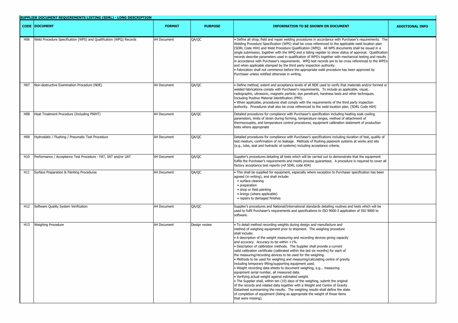
H06 Weld Procedure Specification (WPS) and Qualification (WPQ) Records A4 Document QA/QC • Define all shop, field and repair welding procedures in accordance with Purchaser's requirements. The Welding Procedure Specification (WPS) shall be cross referenced to the applicable weld location plan (SDRL Code H04) and Weld Procedure Qualification (WPQ). All WPS documents shall be issued in a single submission, together with the WPQ and a listing register to show status of approval. Qualification records describe parameters used in qualification of WPS's together with mechanical testing and results in accordance with Purchaser's requirements. WPQ test records are to be cross referenced to the WPS's and when applicable stamped by the third party inspection authority.• Fabrication shall not commence before the appropriate weld procedure has been approved by Purchaser unless notified otherwise in writing.
H07 Non-destructive Examination Procedure (NDE) A4 Document QA/QC • Define method, extent and acceptance levels of all NDE used to verify that materials and/or formed or welded fabrications comply with Purchaser's requirements. To include as applicable, visual, radiographic, ultrasonic, magnetic particle, dye penetrant, hardness tests and other techniques. Including Positive Material Identification (PMI).• When applicable, procedures shall comply with the requirements of the third party inspection authority. Procedures shall also be cross referenced to the weld location plan. (SDRL Code H04)
H08 Heat Treatment Procedure (Including PWHT) A4 Document QA/QC Detailed procedures for compliance with Purchaser's specification including heating soak cooling parameters, limits of strain during forming, temperature ranges, method of attachment of thermocouples, and temperature control procedures, equipment calibration statement of production tests where appropriate
H09 Hydrostatic / Flushing / Pneumatic Test Procedure A4 Document QA/QC Detailed procedures for compliance with Purchaser's specifications including duration of test, quality of test medium, confirmation of no leakage. Methods of flushing pipework systems at works and site (e.g., lube, seal and hydraulic oil systems) including acceptance criteria.
H10 Performance / Acceptance Test Procedure - FAT, SAT and/or UAT A4 Document QA/QC Supplier’s procedures detailing all tests which will be carried out to demonstrate that the equipment fulfils the Purchaser’s requirements and meets process guarantees. A procedure is required to cover all factory acceptance test reports (ref SDRL code K04)
H11 Surface Preparation & Painting Procedures A4 Document QA/QC • This shall be supplied for equipment, especially where exception to Purchaser specification has been agreed (in writing), and shall include: • surface cleaning • preparation • shop or field painting • linings (where applicable) • repairs to damaged finishes
H12 Software Quality System Verification A4 Document QA/QC Supplier’s procedures and National/International standards detailing routines and tests which will be used to fulfil Purchaser’s requirements and specifications to ISO 9000-3 application of ISO 9000 to software.
H13 Weighing Procedure A4 Document Design review • To detail method recording weights during design and manufacture and method of weighing equipment prior to shipment. The weighing procedure shall include:• A description of the weight measuring and recording devices giving capacity and accuracy. Accuracy to be within +1%.• Description of calibration methods. The Supplier shall provide a current valid calibration certificate (calibrated within the last six months) for each of the measuring/recording devices to be used for the weighing.• Methods to be used for weighing and measuring/calculating centre of gravity including temporary lifting/supporting equipment used.• Weight recording data sheets to document weighing, e.g... measuring equipment serial number, all measured data.• Verifying actual weight against estimated weight.• The Supplier shall, within ten (10) days of the weighing, submit the original of the records and related data together with a Weight and Centre of Gravity Datasheet summarising the results. The weighing results shall define the state of completion of equipment (listing as appropriate the weight of those items that were missing).
CODE DOCUMENT FORMAT PURPOSE INFORMATION TO BE SHOWN ON DOCUMENT ADDITIONAL INFO
SUPPLIER DOCUMENT REQUIREMENTS LISTING (SDRL) - LONG DESCRIPTION
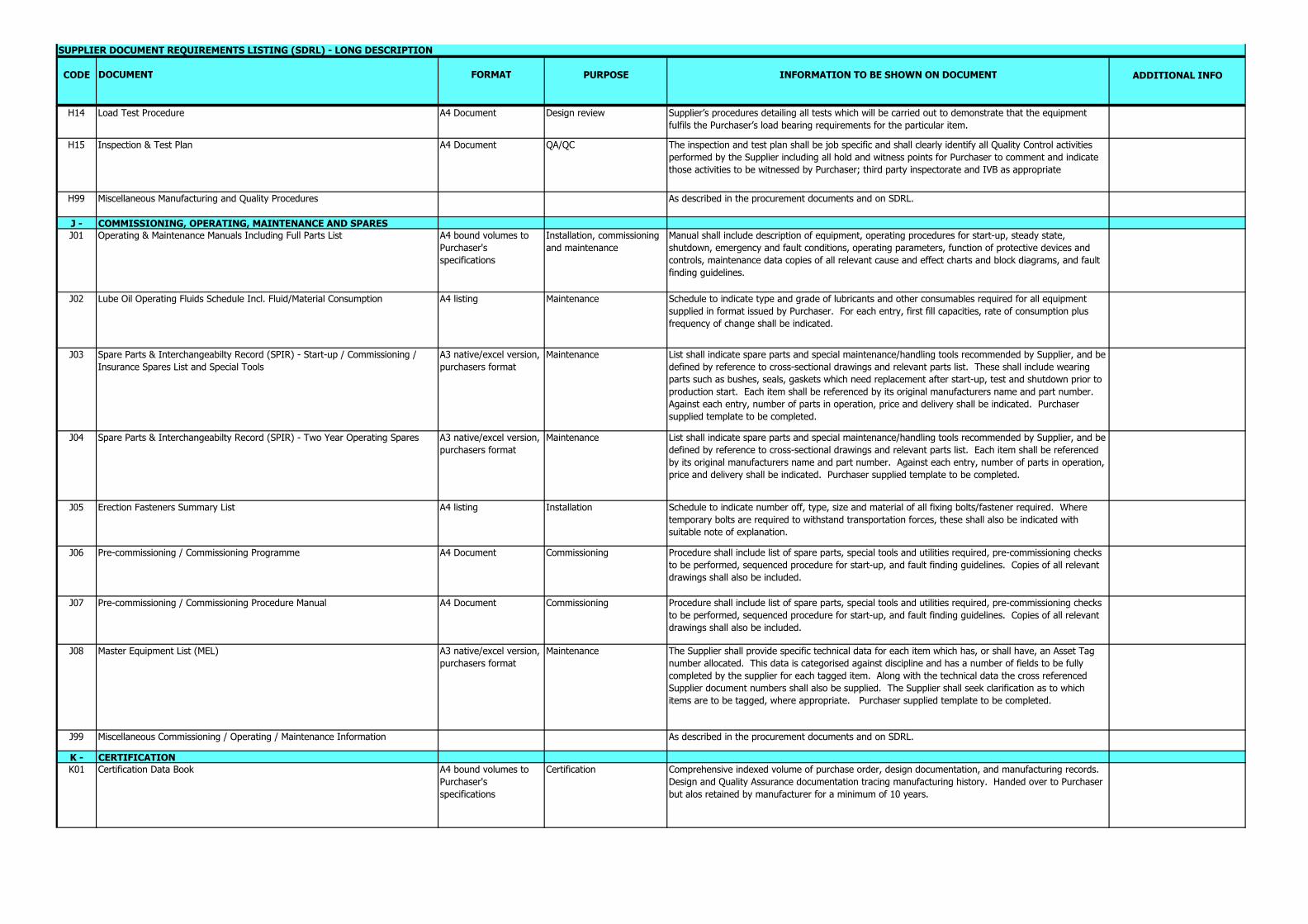
H14 Load Test Procedure A4 Document Design review Supplier’s procedures detailing all tests which will be carried out to demonstrate that the equipment fulfils the Purchaser’s load bearing requirements for the particular item.
H15 Inspection & Test Plan A4 Document QA/QC The inspection and test plan shall be job specific and shall clearly identify all Quality Control activities performed by the Supplier including all hold and witness points for Purchaser to comment and indicate those activities to be witnessed by Purchaser; third party inspectorate and IVB as appropriate
H99 Miscellaneous Manufacturing and Quality Procedures As described in the procurement documents and on SDRL.
J - COMMISSIONING, OPERATING, MAINTENANCE AND SPARESJ01 Operating & Maintenance Manuals Including Full Parts List A4 bound volumes to
Purchaser's specifications
Installation, commissioning and maintenance
Manual shall include description of equipment, operating procedures for start-up, steady state, shutdown, emergency and fault conditions, operating parameters, function of protective devices and controls, maintenance data copies of all relevant cause and effect charts and block diagrams, and fault finding guidelines.
J02 Lube Oil Operating Fluids Schedule Incl. Fluid/Material Consumption A4 listing Maintenance Schedule to indicate type and grade of lubricants and other consumables required for all equipment supplied in format issued by Purchaser. For each entry, first fill capacities, rate of consumption plus frequency of change shall be indicated.
J03 Spare Parts & Interchangeabilty Record (SPIR) - Start-up / Commissioning / Insurance Spares List and Special Tools
A3 native/excel version, purchasers format
Maintenance List shall indicate spare parts and special maintenance/handling tools recommended by Supplier, and be defined by reference to cross-sectional drawings and relevant parts list. These shall include wearing parts such as bushes, seals, gaskets which need replacement after start-up, test and shutdown prior to production start. Each item shall be referenced by its original manufacturers name and part number. Against each entry, number of parts in operation, price and delivery shall be indicated. Purchaser supplied template to be completed.
J04 Spare Parts & Interchangeabilty Record (SPIR) - Two Year Operating Spares A3 native/excel version, purchasers format
Maintenance List shall indicate spare parts and special maintenance/handling tools recommended by Supplier, and be defined by reference to cross-sectional drawings and relevant parts list. Each item shall be referenced by its original manufacturers name and part number. Against each entry, number of parts in operation, price and delivery shall be indicated. Purchaser supplied template to be completed.
J05 Erection Fasteners Summary List A4 listing Installation Schedule to indicate number off, type, size and material of all fixing bolts/fastener required. Where temporary bolts are required to withstand transportation forces, these shall also be indicated with suitable note of explanation.
J06 Pre-commissioning / Commissioning Programme A4 Document Commissioning Procedure shall include list of spare parts, special tools and utilities required, pre-commissioning checks to be performed, sequenced procedure for start-up, and fault finding guidelines. Copies of all relevant drawings shall also be included.
J07 Pre-commissioning / Commissioning Procedure Manual A4 Document Commissioning Procedure shall include list of spare parts, special tools and utilities required, pre-commissioning checks to be performed, sequenced procedure for start-up, and fault finding guidelines. Copies of all relevant drawings shall also be included.
J08 Master Equipment List (MEL) A3 native/excel version, purchasers format
Maintenance The Supplier shall provide specific technical data for each item which has, or shall have, an Asset Tag number allocated. This data is categorised against discipline and has a number of fields to be fully completed by the supplier for each tagged item. Along with the technical data the cross referenced Supplier document numbers shall also be supplied. The Supplier shall seek clarification as to which items are to be tagged, where appropriate. Purchaser supplied template to be completed.
J99 Miscellaneous Commissioning / Operating / Maintenance Information As described in the procurement documents and on SDRL.
K - CERTIFICATIONK01 Certification Data Book A4 bound volumes to
Purchaser's specifications
Certification Comprehensive indexed volume of purchase order, design documentation, and manufacturing records. Design and Quality Assurance documentation tracing manufacturing history. Handed over to Purchaser but alos retained by manufacturer for a minimum of 10 years.

CODE DOCUMENT FORMAT PURPOSE INFORMATION TO BE SHOWN ON DOCUMENT ADDITIONAL INFO
SUPPLIER DOCUMENT REQUIREMENTS LISTING (SDRL) - LONG DESCRIPTION
K02 ATEX / IECE Hazardous Area Certification and Schedule A4 Document Certification • Certificate issued by a recognised independents authority indicating that a type test has satisfied the specified standards, e.g., ATEX, EMC, LV Regs, FIRESAFE. Certification not in the English language shall be supplied with a verified translation.• Read in conjunction with MM-P-G-00-GG-018 Instruction to Suppliers – Drawing and Data Requirements.
K03 Performance Test Report A4 Document QA/QC • Report shall include the following: • Description of how test was conducted, including all pertinent items of Data Code P01 below. • Method of calculating results. • Acceptance criteria. • Log of test readings, signed by Purchaser's representative and third party inspection authority (when applicable). • Calculations of results, taking into account the accuracy of the results. • Problems encountered during the test, and corrective actions taken
K04 Factory Acceptance Test Report (FAT) A4 Document QA/QC Report on performance/functional tests carried out in the factory to demonstrate the equipment suitability to fulfil the duty specified. This report to include certificates as appropriate, tests for overspeed, balancing, shaft mechanical and electrical run out, and vibration. FAT reports on electrical and instrument control equipment shall include high voltage pressure tests and insulation resistance certificates.
K05 Vibration Report A4 Document QA/QC Test report of vibration performance during factory acceptance testing, including mechanical and electrical run out for displacement measuring systems during mechanical and performance testing of machinery.
K06 Noise Report A4 Document QA/QC Report to compare actual noise sound pressure and sound power level output with predictions stated in noise level data sheets (SDRL Code F11)
K07 CE Declarations of Conformity A4 Document QA/QC Supplier is required to comply with all applicable directives for their scope of supply, and issue a declaration (Declaration of Conformity) for the equipment.
K08 Weight Report A4 Document Input to Weight Monitoring System
As described in MM-P-G-00-GG-018 Instruction to Suppliers – Drawing and Data Requirements
K09 Load Test Results A4 certificate Certification Certificate/s detailing test results which demonstrate that the equipment fulfils the Purchaser’s load bearing requirements for the particular item.
K10 Certificate of Conformity (BS EN 10204 2.1) (*) A4 certificate Certification Manufacturers statement of compliance with the order.
K11 BS EN 10204 - 2.2 Material Certificate A4 certificate Certification Manufacturers statement of compliance with the order based on results of a non-specific inspection/test (s).
K12 BS EN 10204 - 3.1 Material Certificate A4 certificate Certification Certificates in compliance with E.N. 10204 3.1 or otherwise as required by PO Documentation shall include as a minimum chemical analysis, specification range analysis, mechanical test results, heat treated condition for the product supplied to the Purchaser. Unless otherwise requested in Design Specification and Quality Requirements Specification included in the Purchase documentation. Certificates must be fully traceable to each component by means of a unique numbering system, together with supplementary material placement drawings when necessary. Certificates and material placement drawings (when required) shall be verified by suppliers inspection department which shall be independent of manufacturing.
K13 BS EN 10204 - 3.2 Material Certificate A4 certificate Certification Certificates in compliance with E.N. 10204 3.2. or otherwise as required by PO Documentation shall include as a minimum chemical analysis, specification range analysis, mechanical test results, heat treated condition for the product supplied to the Purchaser. Unless otherwise requested in Design Specification and Quality Requirements Specification included in the Purchase documentation. Certificates must be fully traceable to each component by means of a unique numbering system, together with supplementary material placement drawings when necessary. Certificates and material placement drawings shall be verified by an independent inspection authority.
K14 Certificate of Compliance (e.g. Vessel Code) A4 certificate Certification Certificate issued by the manufacturer confirming that the product complies with the purchase order requirements and current EC legislation.

CODE DOCUMENT FORMAT PURPOSE INFORMATION TO BE SHOWN ON DOCUMENT ADDITIONAL INFO
SUPPLIER DOCUMENT REQUIREMENTS LISTING (SDRL) - LONG DESCRIPTION
K15 Weldability Data A4 Document QA/QC Information on the weldability of materials including process and heat inputs, material thickness, pre-heat, PWHT, chemical analysis of test materials, mechanical test results. NB This is not a replacement for code H04 which is specific to the equipment and materials being fabricated.
K99 Miscellaneous Certification As described in the procurement documents and on SDRL.
L - TEST & INSPECTION REPORTSL01 Material Test Cert.-Mill Certificates (BSEN.10204 3.1; 3.2; 2.1; 2.2 )
DO NOT USEA4 certificate Certification Certificates in compliance with E.N. 10204 3.1 or 3.2. or otherwise as required by PO Documentation
shall include as a minimum chemical analysis, specification range analysis, mechanical test results, heat treated condition for the product supplied to the Purchaser. Unless otherwise requested in Design Specification and Quality Requirements Specification included in the Purchase documentation. Certificates must be fully traceable to each component by means of a unique numbering system, together with supplementary material placement drawings when necessary. Certificates and material placement drawings (when required) shall be verified by inspection authority. Each certificate shall state that it is to EN 10204 3.1 or 3.2, or 2.2. for non-pressure retaining equipment.
L02 Welder Performance Qualifications A4 certificate QA/QC Welders name, identification and positions to be recorded to code requirements with approval by third party inspection authority when applicable, using approved weld procedure.
L03 Non-Destructive Examination Operator Qualifications A4 certificate Certification Copies of Qualification Certificates for the technicians/operators signing certificates within Data Code L05. Certificates to state Purchaser's purchase order number.
L04 Production Test Results (Including Welding) A4 certificate Certification Results of tensile, ductility hardness and impact tests carried out on production tests.• Includes production weld test results.• Certificates to state Purchaser's purchase order number, tag number (of other unique identification) to permit traceability of tested equipment, item or piping system. Supplementary marked-up piping isometrics shall be included when necessary to define extent of testing, those being verified by the Purchaser, when required.
L05 Non-Destructive Examination Records A4 certificate Certification a) Radiography• Results of radiography tests carried out and signed by a qualified technician. Detailed reports are to state Purchaser's order number, and to include the procedure used, acceptance level and results obtained in accordance with Purchaser's specified standard. Reference shall be made to applicable operator qualification certificates, and approvals by third party inspection authority shall be gained when necessary.b) Ultrasonic Examination• Certificate confirming that acceptable results have been obtained on examinations carried out to the specified standard and stating the equipment used, calibration standard and procedure adopted. The certificate shall be signed by a qualified operator. Reference shall be made to applicable NDT operation qualification certificates, and approvals by third party inspection authority shall be gained when necessary.c) Crack Detection, covering Magnetic Particle Inspection (MPI) and DYE Penetrant Inspection (DPI).• Details as in (B) above.d) Positive Material Identification (PMI)• Results of PMI testing shall be maintained on a standardised format and signed by a Qualified Technician. Standardised format and incorporated into the Suppliers Manufacturing Data Manual (K01)
Note: When applicable, NDE Records shall be supplemented with weld history drawings verified by Purchaser (and the third party inspection authority, when necessary).
L06 Heat Treatment Records A4 certificate Certification • Pyrometric charts or certificates confirming the heat treatment cycles have been conducted to Purchaser's requirements.• Certificates to state Purchaser's purchase order number, item number, and identification to permit traceability to the heat treated component or materials.
L07 Material Traceability Records Maximum size A1. Scale drawing
QA/QC • Location plans/records with an identification system cross-referring to the individual material certificates.• When applicable, material placement drawings shall be verified by the Purchaser and/or third party inspection authority.
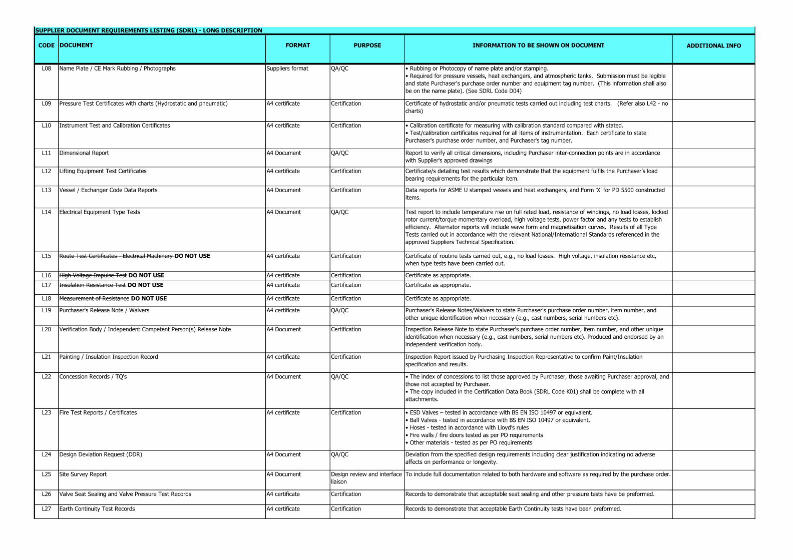
CODE DOCUMENT FORMAT PURPOSE INFORMATION TO BE SHOWN ON DOCUMENT ADDITIONAL INFO
SUPPLIER DOCUMENT REQUIREMENTS LISTING (SDRL) - LONG DESCRIPTION
L08 Name Plate / CE Mark Rubbing / Photographs Suppliers format QA/QC • Rubbing or Photocopy of name plate and/or stamping.• Required for pressure vessels, heat exchangers, and atmospheric tanks. Submission must be legible and state Purchaser's purchase order number and equipment tag number. (This information shall also be on the name plate). (See SDRL Code D04)
L09 Pressure Test Certificates with charts (Hydrostatic and pneumatic) A4 certificate Certification Certificate of hydrostatic and/or pneumatic tests carried out including test charts. (Refer also L42 - no charts)
L10 Instrument Test and Calibration Certificates A4 certificate Certification • Calibration certificate for measuring with calibration standard compared with stated.• Test/calibration certificates required for all items of instrumentation. Each certificate to state Purchaser's purchase order number, and Purchaser's tag number.
L11 Dimensional Report A4 Document QA/QC Report to verify all critical dimensions, including Purchaser inter-connection points are in accordance with Supplier's approved drawings
L12 Lifting Equipment Test Certificates A4 certificate Certification Certificate/s detailing test results which demonstrate that the equipment fulfils the Purchaser’s load bearing requirements for the particular item.
L13 Vessel / Exchanger Code Data Reports A4 Document Certification Data reports for ASME U stamped vessels and heat exchangers, and Form ‘X’ for PD 5500 constructed items.
L14 Electrical Equipment Type Tests A4 Document QA/QC Test report to include temperature rise on full rated load, resistance of windings, no load losses, locked rotor current/torque momentary overload, high voltage tests, power factor and any tests to establish efficiency. Alternator reports will include wave form and magnetisation curves. Results of all Type Tests carried out in accordance with the relevant National/International Standards referenced in the approved Suppliers Technical Specification.
L15 Route Test Certificates - Electrical Machinery DO NOT USE A4 certificate Certification Certificate of routine tests carried out, e.g., no load losses. High voltage, insulation resistance etc, when type tests have been carried out.
L16 High Voltage Impulse Test DO NOT USE A4 certificate Certification Certificate as appropriate.L17 Insulation Resistance Test DO NOT USE A4 certificate Certification Certificate as appropriate.
L18 Measurement of Resistance DO NOT USE A4 certificate Certification Certificate as appropriate.
L19 Purchaser's Release Note / Waivers A4 certificate QA/QC Purchaser's Release Notes/Waivers to state Purchaser's purchase order number, item number, and other unique identification when necessary (e.g., cast numbers, serial numbers etc).
L20 Verification Body / Independent Competent Person(s) Release Note A4 Document Certification Inspection Release Note to state Purchaser's purchase order number, item number, and other unique identification when necessary (e.g., cast numbers, serial numbers etc). Produced and endorsed by an independent verification body.
L21 Painting / Insulation Inspection Record A4 certificate Certification Inspection Report issued by Purchasing Inspection Representative to confirm Paint/Insulation specification and results.
L22 Concession Records / TQ's A4 Document QA/QC • The index of concessions to list those approved by Purchaser, those awaiting Purchaser approval, and those not accepted by Purchaser.• The copy included in the Certification Data Book (SDRL Code K01) shall be complete with all attachments.
L23 Fire Test Reports / Certificates A4 certificate Certification • ESD Valves – tested in accordance with BS EN ISO 10497 or equivalent.• Ball Valves - tested in accordance with BS EN ISO 10497 or equivalent.• Hoses - tested in accordance with Lloyd’s rules• Fire walls / fire doors tested as per PO requirements• Other materials - tested as per PO requirements
L24 Design Deviation Request (DDR) A4 Document QA/QC Deviation from the specified design requirements including clear justification indicating no adverse affects on performance or longevity.
L25 Site Survey Report A4 Document Design review and interface liaison
To include full documentation related to both hardware and software as required by the purchase order.
L26 Valve Seat Sealing and Valve Pressure Test Records A4 certificate Certification Records to demonstrate that acceptable seat sealing and other pressure tests have be preformed.
L27 Earth Continuity Test Records A4 certificate Certification Records to demonstrate that acceptable Earth Continuity tests have been preformed.
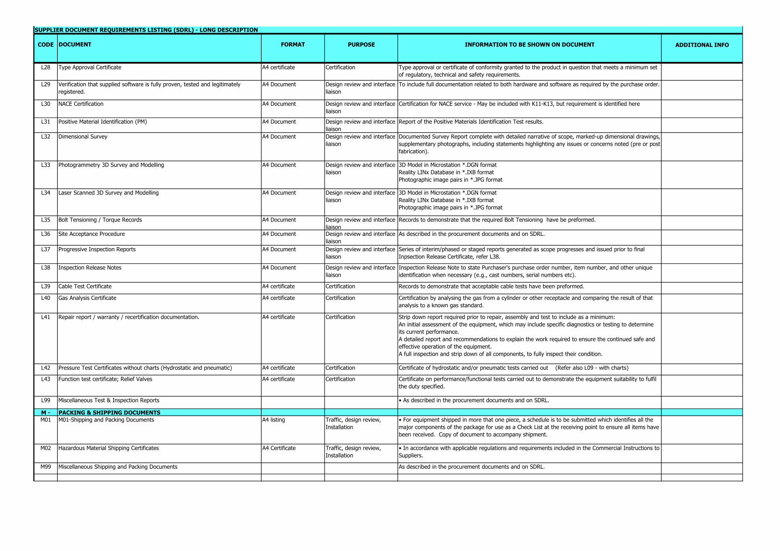
CODE DOCUMENT FORMAT PURPOSE INFORMATION TO BE SHOWN ON DOCUMENT ADDITIONAL INFO
SUPPLIER DOCUMENT REQUIREMENTS LISTING (SDRL) - LONG DESCRIPTION
L28 Type Approval Certificate A4 certificate Certification Type approval or certificate of conformity granted to the product in question that meets a minimum set of regulatory, technical and safety requirements.
L29 Verification that supplied software is fully proven, tested and legitimately registered.
A4 Document Design review and interface liaison
To include full documentation related to both hardware and software as required by the purchase order.
L30 NACE Certification A4 Document Design review and interface liaison
Certification for NACE service - May be included with K11-K13, but requirement is identified here
L31 Positive Material Identification (PM) A4 Document Design review and interface liaison
Report of the Positive Materials Identification Test results.
L32 Dimensional Survey A4 Document Design review and interface liaison
Documented Survey Report complete with detailed narrative of scope, marked-up dimensional drawings, supplementary photographs, including statements highlighting any issues or concerns noted (pre or post fabrication).
L33 Photogrammetry 3D Survey and Modelling A4 Document Design review and interface liaison
3D Model in Microstation *.DGN format Reality LINx Database in *.IXB format Photographic image pairs in *.JPG format
L34 Laser Scanned 3D Survey and Modelling A4 Document Design review and interface liaison
3D Model in Microstation *.DGN format Reality LINx Database in *.IXB format Photographic image pairs in *.JPG format
L35 Bolt Tensioning / Torque Records A4 Document Design review and interface liaison
Records to demonstrate that the required Bolt Tensioning have be preformed.
L36 Site Acceptance Procedure A4 Document Design review and interface liaison
As described in the procurement documents and on SDRL.
L37 Progressive Inspection Reports A4 Document Design review and interface liaison
Series of interim/phased or staged reports generated as scope progresses and issued prior to final Inpsection Release Certificate, refer L38.
L38 Inspection Release Notes A4 Document Design review and interface liaison
Inspection Release Note to state Purchaser's purchase order number, item number, and other unique identification when necessary (e.g., cast numbers, serial numbers etc).
L39 Cable Test Certificate A4 certificate Certification Records to demonstrate that acceptable cable tests have been preformed.
L40 Gas Analysis Certificate A4 certificate Certification Certification by analysing the gas from a cylinder or other receptacle and comparing the result of that analysis to a known gas standard.
L41 Repair report / warranty / recertification documentation. A4 certificate Certification Strip down report required prior to repair, assembly and test to include as a minimum:An initial assessment of the equipment, which may include specific diagnostics or testing to determine its current performance.A detailed report and recommendations to explain the work required to ensure the continued safe and effective operation of the equipment.A full inspection and strip down of all components, to fully inspect their condition.
L42 Pressure Test Certificates without charts (Hydrostatic and pneumatic) A4 certificate Certification Certificate of hydrostatic and/or pneumatic tests carried out (Refer also L09 - with charts)
L43 Function test certificate; Relief Valves A4 certificate Certification Certificate on performance/functional tests carried out to demonstrate the equipment suitability to fulfil the duty specified.
L99 Miscellaneous Test & Inspection Reports • As described in the procurement documents and on SDRL.
M - PACKING & SHIPPING DOCUMENTSM01 M01-Shipping and Packing Documents A4 listing Traffic, design review,
Installation• For equipment shipped in more that one piece, a schedule is to be submitted which identifies all the major components of the package for use as a Check List at the receiving point to ensure all items have been received. Copy of document to accompany shipment.
M02 Hazardous Material Shipping Certificates A4 Certificate Traffic, design review, Installation
• In accordance with applicable regulations and requirements included in the Commercial Instructions to Suppliers.
M99 Miscellaneous Shipping and Packing Documents As described in the procurement documents and on SDRL.