supplementary reference and faq - nerc 200717 protection system maintenan… · iii prc‐005‐2...
TRANSCRIPT
3353 Peachtree Road NE Suite 600, North Tower
Atlanta, GA 30326 404-446-2560 | www.nerc.com
Supplementary Reference and FAQ PRC-005-2 Protection System Maintenance
October 2012

ii PRC‐005‐2 Supplementary Reference and FAQ – October 2012 Adopted by the NERC BOT November 2012
Table of Contents
Table of Contents .............................................................................................................................ii
1. Introduction and Summary ......................................................................................................... 1
2. Need for Verifying Protection System Performance .................................................................. 2
2.1 Existing NERC Standards for Protection System Maintenance and Testing ......................... 2
2.2 Protection System Definition ................................................................................................ 3
2.3 Applicability of New Protection System Maintenance Standards ........................................ 3
2.3.1 Frequently Asked Questions: ............................................................................................. 4
2.4.1 Frequently Asked Questions: ............................................................................................. 6
3. Protection Systems Product Generations ................................................................................... 8
4. Definitions ................................................................................................................................. 10
4.1 Frequently Asked Questions: .............................................................................................. 11
5. Time‐Based Maintenance (TBM) Programs .............................................................................. 13
5.1 Maintenance Practices ....................................................................................................... 13
5.1.1 Frequently Asked Questions: ....................................................................................... 15
5.2 Extending Time‐Based Maintenance .............................................................................. 16
5.2.1 Frequently Asked Questions: ....................................................................................... 16
6. Condition‐Based Maintenance (CBM) Programs ...................................................................... 18
6.1 Frequently Asked Questions: .............................................................................................. 18
7. Time‐Based Versus Condition‐Based Maintenance .................................................................. 20
7.1 Frequently Asked Questions: .............................................................................................. 20
8. Maximum Allowable Verification Intervals............................................................................... 26
8.1 Maintenance Tests .............................................................................................................. 26
8.1.1 Table of Maximum Allowable Verification Intervals.................................................... 26

iii PRC‐005‐2 Supplementary Reference and FAQ – October 2012 Adopted by the NERC BOT November 2012
8.1.2 Additional Notes for Tables 1‐1 through 1‐5 and Table 3 ........................................... 28
8.1.3 Frequently Asked Questions: ....................................................................................... 29
8.2 Retention of Records .......................................................................................................... 34
8.2.1 Frequently Asked Questions: ....................................................................................... 34
8.3 Basis for Table 1 Intervals ................................................................................................... 36
8.4 Basis for Extended Maintenance Intervals for Microprocessor Relays .............................. 37
9. Performance‐Based Maintenance Process ............................................................................... 40
9.1 Minimum Sample Size......................................................................................................... 41
9.2 Frequently Asked Questions: .............................................................................................. 43
10. Overlapping the Verification of Sections of the Protection System ....................................... 54
10.1 Frequently Asked Questions: ............................................................................................ 54
11. Monitoring by Analysis of Fault Records ................................................................................ 55
11.1 Frequently Asked Questions: ............................................................................................ 56
12. Importance of Relay Settings in Maintenance Programs ....................................................... 57
12.1 Frequently Asked Questions: ............................................................................................ 57
13. Self‐Monitoring Capabilities and Limitations.......................................................................... 60
13.1 Frequently Asked Questions: ............................................................................................ 61
14. Notification of Protection System Failures ............................................................................. 62
15. Maintenance Activities ........................................................................................................... 63
15.1 Protective Relays (Table 1‐1) ............................................................................................ 63
15.1.1 Frequently Asked Questions: ..................................................................................... 63
15.2 Voltage & Current Sensing Devices (Table 1‐3) ............................................................ 63
15.2.1 Frequently Asked Questions: ..................................................................................... 65
15.3 Control circuitry associated with protective functions (Table 1‐5) .............................. 66
15.3.1 Frequently Asked Questions: ..................................................................................... 68

iv PRC‐005‐2 Supplementary Reference and FAQ – October 2012 Adopted by the NERC BOT November 2012
15.4 Batteries and DC Supplies (Table 1‐4) ........................................................................... 70
15.4.1 Frequently Asked Questions: ..................................................................................... 71
15.5 Associated communications equipment (Table 1‐2) ........................................................ 85
15.5.1 Frequently Asked Questions: ..................................................................................... 87
15.6 Alarms (Table 2) ................................................................................................................ 90
15.6.1 Frequently Asked Questions: ..................................................................................... 90
15.7 Distributed UFLS and Distributed UVLS Systems (Table 3) ............................................... 91
15.7.1 Frequently Asked Questions: ..................................................................................... 92
15.8 Examples of Evidence of Compliance ............................................................................... 92
15.8.1 Frequently Asked Questions: ......................................................................................... 92
References .................................................................................................................................... 94
Figures ........................................................................................................................................... 96
Figure 1: Typical Transmission System ..................................................................................... 96
Figure 2: Typical Generation System ........................................................................................ 97
Figure 1 & 2 Legend – components of Protection Systems .......................................................... 98
Appendix A .................................................................................................................................... 99
Appendix B .................................................................................................................................. 102
Protection System Maintenance Standard Drafting Team ......................................................... 102
PRC‐005‐2 Supplementary Reference and FAQ – October 2012 Adopted by the NERC BOT November 2012 1
1. Introduction and Summary Note: This supplementary reference for PRC‐005‐2 is neither mandatory nor enforceable. NERC currently has four Reliability Standards that are mandatory and enforceable in the United States and Canada and address various aspects of maintenance and testing of Protection and Control Systems. These standards are:
PRC‐005‐1 — Transmission and Generation Protection System Maintenance and Testing
PRC‐008‐0 — Underfrequency Load Shedding Equipment Maintenance Programs
PRC‐011‐0 — UVLS System Maintenance and Testing
PRC‐017‐0 — Special Protection System Maintenance and Testing
While these standards require that applicable entities have a maintenance program for Protection Systems, and that these entities must be able to demonstrate they are carrying out such a program, there are no specifics regarding the technical requirements for Protection System maintenance programs. Furthermore, FERC Order 693 directed additional modifications respective to Protection System maintenance programs. PRC‐005‐2 combines and replaces PRC‐005, PRC‐008, PRC‐011 and PRC‐017.
PRC‐005‐2 Supplementary Reference and FAQ – October 2012 Adopted by the NERC BOT November 2012 2
2. Need for Verifying Protection System Performance Protective relays have been described as silent sentinels, and do not generally demonstrate their performance until a Fault or other power system problem requires that they operate to protect power system Elements, or even the entire Bulk Electric System (BES). Lacking Faults, switching operations or system problems, the Protection Systems may not operate, beyond static operation, for extended periods. A Misoperation ‐ a false operation of a Protection System or a failure of the Protection System to operate, as designed, when needed ‐ can result in equipment damage, personnel hazards, and wide‐area Disturbances or unnecessary customer outages. Maintenance or testing programs are used to determine the performance and availability of Protection Systems.
Typically, utilities have tested Protection Systems at fixed time intervals, unless they had some incidental evidence that a particular Protection System was not behaving as expected. Testing practices vary widely across the industry. Testing has included system functionality, calibration of measuring devices, and correctness of settings. Typically, a Protection System must be visited at its installation site and, in many cases, removed from service for this testing.
Fundamentally, a Reliability Standard for Protection System Maintenance and Testing requires the performance of the maintenance activities that are necessary to detect and correct plausible age and service related degradation of the Protection System components, such that a properly built and commissioned Protection System will continue to function as designed over its service life.
Similarly station batteries, which are an important part of the station dc supply, are not called upon to provide instantaneous dc power to the Protection System until power is required by the Protection System to operate circuit breakers or interrupting devices to clear Faults or to isolate equipment.
2.1 Existing NERC Standards for Protection System Maintenance and Testing
For critical BES protection functions, NERC standards have required that each utility or asset owner define a testing program. The starting point is the existing Standard PRC‐005, briefly restated as follows:
Purpose: To document and implement programs for the maintenance of all Protection Systems affecting the reliability of the Bulk Electric System (BES) so that these Protection Systems are kept in working order.
PRC‐005‐1 is not specific on where the boundaries of the Protection Systems lie. However, the definition of Protection System in the NERC Glossary of Terms used in Reliability Standards indicates what must be included as a minimum.
At the beginning of the project to develop PRC‐005‐2, the definition of Protection System was:
Protective relays, associated communications Systems, voltage and current sensing devices, station batteries and dc control circuitry.
Applicability: Owners of generation and transmission Protection Systems.

PRC‐005‐2 Supplementary Reference and FAQ – October 2012 Adopted by the NERC BOT November 2012 3
Requirements: The owner shall have a documented maintenance program with test intervals. The owner must keep records showing that the maintenance was performed at the specified intervals.
2.2 Protection System Definition
The most recently approved definition of Protection Systems is:
Protective relays which respond to electrical quantities,
Communications systems necessary for correct operation of protective functions,
Voltage and current sensing devices providing inputs to protective relays,
Station dc supply associated with protective functions (including station batteries, battery chargers, and non‐battery‐based dc supply), and
Control circuitry associated with protective functions through the trip coil(s) of the circuit breakers or other interrupting devices.
2.3 Applicability of New Protection System Maintenance Standards
The BES purpose is to transfer bulk power. The applicability language has been changed from the original PRC‐005:
“...affecting the reliability of the Bulk Electric System (BES)…”
To the present language:
“…that are installed for the purpose of detecting Faults on BES Elements (lines, buses, transformers, etc.).”
The drafting team intends that this standard will follow with any definition of the Bulk Electric System. There should be no ambiguity; if the Element is a BES Element, then the Protection System protecting that Element should then be included within this standard. If there is regional variation to the definition, then there will be a corresponding regional variation to the Protection Systems that fall under this standard.
There is no way for the Standard Drafting Team to know whether a specific 230KV line, 115KV line (even 69KV line), for example, should be included or excluded. Therefore, the team set the clear intent that the standard language should simply be applicable to Protection Systems for BES Elements.
The BES is a NERC defined term that, from time to time, may undergo revisions. Additionally, there may even be regional variations that are allowed in the present and future definitions. See the NERC Glossary of Terms for the present, in‐force definition. See the applicable Regional Reliability Organization for any applicable allowed variations.
While this standard will undergo revisions in the future, this standard will not attempt to keep up with revisions to the NERC definition of BES, but, rather, simply make BES Protection Systems applicable.
The Standard is applied to Generator Owners (GO) and Transmission Owners (TO) because GOs and TOs have equipment that is BES equipment. The standard brings in Distribution Providers (DP) because, depending on the station configuration of a particular substation, there may be Protection System equipment installed at a non‐transmission voltage level (Distribution

PRC‐005‐2 Supplementary Reference and FAQ – October 2012 Adopted by the NERC BOT November 2012 4
Provider equipment) that is wholly or partially installed to protect the BES. PRC‐005‐2 would apply to this equipment. An example is underfrequency load‐shedding, which is frequently applied well down into the distribution system to meet PRC‐007‐0.
As this standard is intended to replace the existing PRC‐005, PRC‐008, PRC‐011 and PRC‐017, those standards are used in the construction of this revision of PRC‐005‐1. Much of the original intent of those standards was carried forward whenever it was possible to continue the intent without a disagreement with FERC Order 693. For example, the original PRC‐008 was constructed quite differently than the original PRC‐005. The drafting team agrees with the intent of this and notes that distributed tripping schemes would have to exhibit multiple failures to trip before they would prove to be significant, as opposed to a single failure to trip of, for example, a transmission Protection System Bus Differential lock‐out relay. While many failures of these distribution breakers could add up to be significant, it is also believed that distribution breakers are operated often on just Fault clearing duty; and, therefore, the distribution circuit breakers are operated at least as frequently as stipulated in any requirement in this standard.
Additionally, since this standard will now replace PRC‐011, it will be important to make the distinction between under‐voltage Protection Systems that protect individual Loads and Protection Systems that are UVLS schemes that protect the BES. Any UVLS scheme that had been applicable under PRC‐011 will now be applicable under this revision of PRC‐005‐1. An example of an under‐voltage load‐shedding scheme that is not applicable to this standard is one in which the tripping action was intended to prevent low distribution voltage to a specific Load from a Transmission system that was intact except for the line that was out of service, as opposed to preventing a Cascading outage or Transmission system collapse.
It had been correctly noted that the devices needed for PRC‐011 are the very same types of devices needed in PRC‐005.
Thus, a standard written for Protection Systems of the BES can easily make the needed requirements for Protection Systems, and replace some other standards at the same time.
2.3.1 Frequently Asked Questions:
What exactly is the BES, or Bulk Electric System? BES is the abbreviation for Bulk Electric System. BES is a term in the Glossary of Terms used in Reliability Standards, and is not being modified within this draft standard. NERC's approved definition of Bulk Electric System is:
As defined by the Regional Reliability Organization, the electrical generation resources, transmission lines, Interconnections with neighboring Systems, and associated equipment, generally operated at voltages of 100 kV or higher. Radial transmission Facilities serving only Load with one transmission source are generally not included in this definition.
The BES definition is presently undergoing the process of revision.
Each regional entity implements a definition of the Bulk Electric System that is based on this NERC definition; in some cases, supplemented by additional criteria. These regional definitions have been documented and provided to FERC as part of a June 14, 2007 Informational Filing.

PRC‐005‐2 Supplementary Reference and FAQ – October 2012 Adopted by the NERC BOT November 2012 5
Why is Distribution Provider included within the Applicable Entities and as a responsible entity within several of the requirements? Wouldn’t anyone having relevant Facilities be a Transmission Owner? Depending on the station configuration of a particular substation, there may be Protection System equipment installed at a non‐transmission voltage level (Distribution Provider equipment) that is wholly or partially installed to protect the BES. PRC‐005‐2 would apply to this equipment. An example is underfrequency load‐shedding, which is frequently applied well down into the distribution system to meet PRC‐007‐0.
We have an under voltage load-shedding (UVLS) system in place that prevents one of our distribution substations from supplying extremely low voltage in the case of a specific transmission line outage. The transmission line is part of the BES. Does this mean that our UVLS system falls within this standard?
The situation, as stated, indicates that the tripping action was intended to prevent low distribution voltage to a specific Load from a Transmission System that was intact, except for the line that was out of service, as opposed to preventing Cascading outage or Transmission System Collapse. This standard is not applicable to this UVLS.
We have a UFLS or UVLS scheme that sheds the necessary Load through distribution-side circuit breakers and circuit reclosers. Do the trip-test requirements for circuit breakers apply to our situation?
No. Distributed tripping schemes would have to exhibit multiple failures to trip before they would prove to be significant, as opposed to a single failure to trip of, for example, a transmission Protection System bus differential lock‐out relay. While many failures of these distribution breakers could add up to be significant, it is also believed that distribution breakers are operated often on just Fault clearing duty; and, therefore, the distribution circuit breakers are operated at least as frequently as any requirements that might have appeared in this standard.
We have a UFLS scheme that, in some locales, sheds the necessary Load through non-BES circuit breakers and, occasionally, even circuit switchers. Do the trip-test requirements for circuit breakers apply to our situation?
If your “non‐BES circuit breaker” has been brought into this standard by the inclusion of UFLS requirements, and otherwise would not have been brought into this standard, then the answer is that there are no trip‐test requirements. For these devices that are otherwise non‐BES assets, these tripping schemes would have to exhibit multiple failures to trip before they would prove to be as significant as, for example, a single failure to trip of a transmission Protection System bus differential lock‐out relay.
How does the “Facilities” section of “Applicability” track with the standards that will be retired once PRC-005-2 becomes effective?
In establishing PRC‐005‐2, the drafting team has combined legacy standards PRC‐005‐1, PRC‐008‐0, PRC‐011‐0, and PRC‐017‐0. The merger of the subject matter of these standards is reflected in Applicability 4.2.

PRC‐005‐2 Supplementary Reference and FAQ – October 2012 Adopted by the NERC BOT November 2012 6
The intent of the drafting team is that the legacy standards be reflected in PRC‐005‐2 as follows:
Applicability of PRC‐005‐1 for Protection Systems relating to non‐generator elements of the BES is addressed in 4.2.1;
Applicability of PRC‐008‐0 for underfrequency load shedding systems is addressed in 4.2.2;
Applicability of PRC‐011‐0 for undervoltage load shedding relays is addressed in 4.2.3;
Applicability of PRC‐017‐0 for Special Protection Systems is addressed in 4.2.4;
Applicability of PRC‐005‐1 for Protection Systems for BES generators is addressed in 4.2.5.
2.4 Applicable Relays The NERC Glossary definition has a Protection System including relays, dc supply, current and voltage sensing devices, dc control circuitry and associated communications circuits. The relays to which this standard applies are those protective relays that respond to electrical quantities and provide a trip output to trip coils, dc control circuitry or associated communications equipment. This definition extends to IEEE Device No. 86 (lockout relay) and IEEE Device No. 94 (tripping or trip‐free relay), as these devices are tripping relays that respond to the trip signal of the protective relay that processed the signals from the current and voltage‐sensing devices.
Relays that respond to non‐electrical inputs or impulses (such as, but not limited to, vibration, pressure, seismic, thermal or gas accumulation) are not included.
2.4.1 Frequently Asked Questions: Are power circuit reclosers, reclosing relays, closing circuits and auto-restoration schemes covered in this Standard?
No. This standard covers protective relays that use electrical quantity measurements to determine anomalies and to trip a portion of the BES. Reclosers, reclosing relays, closing circuits and auto‐restoration schemes are used to cause devices to close, as opposed to electrical‐measurement relays and their associated circuits that cause circuit interruption from the BES; such closing devices and schemes are more appropriately covered under other NERC standards. There is one notable exception: Since PRC‐017 will be superseded by PRC‐005‐2, then if a Special Protection System (previously covered by PRC‐017) incorporates automatic closing of breakers, then the SPS‐related closing devices must be tested accordingly.
I use my protective relays only as sources of metered quantities and breaker status for SCADA and EMS through a substation distributed RTU or data concentrator to the control center. What are the maintenance requirements for the relays?
This standard addresses Protection Systems that are installed for the purpose of detecting Faults on BES Elements (lines, buses, transformers, etc.). Protective relays, providing only the functions mentioned in the question, are not included.
Are Reverse Power Relays installed on the low-voltage side of distribution banks considered to be components of “Protection Systems that are installed for the purpose of detecting Faults on BES Elements (lines, buses, transformers, etc.)”?

PRC‐005‐2 Supplementary Reference and FAQ – October 2012 Adopted by the NERC BOT November 2012 7
Reverse power relays are often installed to detect situations where the transmission source becomes deenergized and the distribution bank remains energized from a source on the low‐voltage side of the transformer and the settings are calculated based on the charging current of the transformer from the low‐voltage side. Although these relays may operate as a result of a fault on a BES element, they are not ‘installed for the purpose of detecting’ these faults.
Is a Sudden Pressure Relay an auxiliary tripping relay?
No. IEEE C37.2‐2008 assigns the Device No.# 94 to auxiliary tripping relays. Sudden pressure relays are assigned Device No.# 63. Sudden pressure relays are presently excluded from the standard because it does not utilize voltage and/or current measurements to determine anomalies. Devices that use anything other than electrical detection means are excluded. The trip path from a sudden pressure device is a part of the Protection System control circuitry. The sensing element is omitted from PRC‐005‐2 testing requirements because the SDT is unaware of industry‐recognized testing protocol for the sensing elements. The SDT believes that Protection Systems that trip (or can trip) the BES should be included. This position is consistent with the currently‐approved PRC‐005‐1a, consistent with the SAR for Project 2007‐17, and understands this to be consistent with the position of FERC staff.
My mechanical device does not operate electrically and does not have calibration settings; what maintenance activities apply?
You must conduct a test(s) to verify the integrity of any trip circuit that is a part of a Protection System. This standard does not cover circuit breaker maintenance or transformer maintenance. The standard also does not presently cover testing of devices, such as sudden pressure relays (63), temperature relays (49), and other relays which respond to mechanical parameters, rather than electrical parameters. There is an expectation that Fault pressure relays and other non‐electrically initiated devices may become part of some maintenance standard. This standard presently covers trip paths. It might seem incongruous to test a trip path without a present requirement to test the device; and, thus, be arguably more work for nothing. But one simple test to verify the integrity of such a trip path could be (but is not limited to) a voltage presence test, as a dc voltage monitor might do if it were installed monitoring that same circuit.
The standard specifically mentions auxiliary and lock-out relays. What is an auxiliary tripping relay?
An auxiliary relay, IEEE Device No.# 94, is described in IEEE Standard C37.2‐2008 as: “A device that functions to trip a circuit breaker, contactor, or equipment; to permit immediate tripping by other devices; or to prevent immediate reclosing of a circuit interrupter if it should open automatically, even though its closing circuit is maintained closed.”
What is a lock-out relay?
A lock‐out relay, IEEE Device No.# 86, is described in IEEE Standard C37.2 as: “A device that trips and maintains the associated equipment or devices inoperative until it is reset by an operator, either locally or remotely.”
PRC‐005‐2 Supplementary Reference and FAQ – October 2012 Adopted by the NERC BOT November 2012 8
3. Protection Systems Product Generations
The likelihood of failure and the ability to observe the operational state of a critical Protection System both depends on the technological generation of the relays, as well as how long they have been in service. Unlike many other transmission asset groups, protection and control systems have seen dramatic technological changes spanning several generations. During the past 20 years, major functional advances are primarily due to the introduction of microprocessor technology for power system devices, such as primary measuring relays, monitoring devices, control Systems, and telecommunications equipment.
Modern microprocessor‐based relays have six significant traits that impact a maintenance strategy:
Self monitoring capability ‐ the processors can check themselves, peripheral circuits, and some connected substation inputs and outputs, such as trip coil continuity. Most relay users are aware that these relays have self monitoring, but are not focusing on exactly what internal functions are actually being monitored. As explained further below, every element critical to the Protection System must be monitored, or else verified periodically.
Ability to capture Fault records showing how the Protection System responded to a Fault in its zone of protection, or to a nearby Fault for which it is required not to operate.
Ability to meter currents and voltages, as well as status of connected circuit breakers, continuously during non‐Fault times. The relays can compute values, such as MW and MVAR line flows, that are sometimes used for operational purposes, such as SCADA.
Data communications via ports that provide remote access to all of the results of Protection System monitoring, recording and measurement.
Ability to trip or close circuit breakers and switches through the Protection System outputs, on command from remote data communications messages, or from relay front panel button requests.
Construction from electronic components, some of which have shorter technical life or service life than electromechanical components of prior Protection System generations.
There have been significant advances in the technology behind the other components of Protection Systems. Microprocessors are now a part of battery chargers, associated communications equipment, voltage and current‐measuring devices, and even the control circuitry (in the form of software‐latches replacing lock‐out relays, etc.).
Any Protection System component can have self‐monitoring and alarming capability, not just relays. Because of this technology, extended time intervals can find their way into all components of the Protection System.
This standard also recognizes the distinct advantage of using advanced technology to justifiably defer or even eliminate traditional maintenance. Just as a hand‐held calculator does not require routine testing and calibration, neither does a calculation buried in a microprocessor‐
PRC‐005‐2 Supplementary Reference and FAQ – October 2012 Adopted by the NERC BOT November 2012 9
based device that results in a “lock‐out.” Thus, the software‐latch 86 that replaces an electro‐mechanical 86 does not require routine trip testing. Any trip circuitry associated with the “soft 86” would still need applicable verification activities performed, but the actual “86” does not have to be “electrically operated” or even toggled.
PRC‐005‐2 Supplementary Reference and FAQ – October 2012 Adopted by the NERC BOT November 2012 10
4. Definitions
Protection System Maintenance Program (PSMP) — An ongoing program by which Protection System components are kept in working order and proper operation of malfunctioning components is restored. A maintenance program for a specific component includes one or more of the following activities:
Verify — Determine that the component is functioning correctly.
Monitor — Observe the routine in‐service operation of the component.
Test — Apply signals to a component to observe functional performance or output behavior, or to diagnose problems.
Inspect — Detect visible signs of component failure, reduced performance and degradation.
Calibrate — Adjust the operating threshold or measurement accuracy of a measuring element to meet the intended performance requirement.
Unresolved Maintenance Issue – A deficiency identified during a maintenance activity that causes the component to not meet the intended performance, cannot be corrected during the maintenance interval,and requires follow‐up corrective action.
Segment – Protection Systems or components of a consistent design standard, or a particular model or type from a single manufacturer that typically share other common elements. Consistent performance is expected across the entire population of a Segment. A Segment must contain at least sixty (60) individual components.
Component Type ‐ Any one of the five specific elements of the Protection System definition.
Component – A Component is any individual discrete piece of equipment included in a Protection System, including but not limited to a protective relay or current sensing device. The designation of what constitutes a control circuit Component is dependent upon how an entity performs and tracks the testing of the control circuitry. Some entities test their control circuits on a breaker basis whereas others test their circuitry on a local zone of protection basis. Thus, entities are allowed the latitude to designate their own definitions of control circuit Components. Another example of where the entity has some discretion on determining what constitutes a single Component is the voltage and current sensing devices, where the entity may choose either to designate a full three‐phase set of such devices or a single device as a single Component.*
Countable Event – A failure of a Component requiring repair or replacement, any condition discovered during the maintenance activities in Tables 1‐1 through 1‐5 and Table 3 which requires corrective action or a Misoperation attributed to hardware failure or calibration failure. Misoperations due to productdesign errors, software errors, relay settings different from specified settings, Protection SystemComponent configuration errors, or Protection System application errors are not included in Countable Events.

PRC‐005‐2 Supplementary Reference and FAQ – October 2012 Adopted by the NERC BOT November 2012 11
4.1 Frequently Asked Questions:
Why does PRC-005-2 not specifically require maintenance and testing procedures, as reflected in the previous standard, PRC-005-1?
PRC‐005‐1 does not require detailed maintenance and testing procedures, but instead requires summaries of such procedures, and is not clear on what is actually required. PRC‐005‐2 requires a documented maintenance program, and is focused on establishing requirements rather than prescribing methodology to meet those requirements. Between the activities identified in the Tables 1‐1 through 1‐5, Table 2 and Table 3 (collectively the “Tables”), and the various components of the definition established for a “Protection System Maintenance Program,” PRC‐005‐2 establishes the activities and time basis for a Protection System Maintenance Program to a level of detail not previously required.
Please clarify what is meant by “restore” in the definition of maintenance.
The description of “restore” in the definition of a Protection System Maintenance Program addresses corrective activities necessary to assure that the component is returned to working order following the discovery of its failure or malfunction. The Maintenance Activities specified in the Tables do not present any requirements related to Restoration; R5 of the standard does require that the entity “shall demonstrate efforts to correct any identified Unresolved Maintenance Issues.” Some examples of restoration (or correction of Unresolved Maintenance Issues) include, but are not limited to, replacement of capacitors in distance relays to bring them to working order; replacement of relays, or other Protection System components, to bring the Protection System to working order; upgrade of electromechanical or solid‐state protective relays to microprocessor‐based relays following the discovery of failed components. Restoration, as used in this context, is not to be confused with restoration rules as used in system operations. Maintenance activity necessarily includes both the detection of problems and the repairs needed to eliminate those problems. This standard does not identify all of the Protection System problems that must be detected and eliminated, rather it is the intent of this standard that an entity determines the necessary working order for their various devices, and keeps them in working order. If an equipment item is repaired or replaced, then the entity can restart the maintenance‐time‐interval‐clock, if desired; however, the replacement of equipment does not remove any documentation requirements that would have been required to verify compliance with time‐interval requirements. In other words, do not discard maintenance data that goes to verify your work.
The retention of documentation for new and/or replaced equipment is all about proving that the maintenance intervals had been in compliance. For example, a long‐range plan of upgrades might lead an entity to ignore required maintenance; retaining the evidence of prior maintenance that existed before any retirements and upgrades proves compliance with the standard.
Please clarify what is meant by “…demonstrate efforts to correct an Unresolved Maintenance Issue…”; why not measure the completion of the corrective action?
Management of completion of the identified Unresolved Maintenance Issue is a complex topic that falls outside of the scope of this standard. There can be any number of supply, process and management problems that make setting repair deadlines impossible. The SDT specifically chose the phrase “demonstrate efforts to correct” (with guidance from NERC Staff) because of the concern that many more complex Unresolved Maintenance Issues might require greater
PRC‐005‐2 Supplementary Reference and FAQ – October 2012 Adopted by the NERC BOT November 2012 12
than the remaining maintenance interval to resolve (and yet still be a “closed‐end process”). For example, a problem might be identified on a VRLA battery during a six‐month check. In instances such as one that requiring battery replacement as part of the long‐term resolution, it is highly unlikely that the battery could be replaced in time to meet the six‐calendar‐month requirement for this maintenance activity. The SDT does not believe entities should be found in violation of a maintenance program requirement because of the inability to complete a remediation program within the original maintenance interval. The SDT does believe corrective actions should be timely, but concludes it would be impossible to postulate all possible remediation projects; and, therefore, impossible to specify bounding time frames for resolution of all possible Unresolved Maintenance Issues, or what documentation might be sufficient to provide proof that effective corrective action is being undertaken.

PRC‐005‐2 Supplementary Reference and FAQ – October 2012 Adopted by the NERC BOT November 2012 13
5. Time-Based Maintenance (TBM) Programs Time‐based maintenance is the process in which Protection Systems are maintained or verified according to a time schedule. The scheduled program often calls for technicians to travel to the physical site and perform a functional test on Protection System components. However, some components of a TBM program may be conducted from a remote location ‐ for example, tripping a circuit breaker by communicating a trip command to a microprocessor relay to determine if the entire Protection System tripping chain is able to operate the breaker. Similarly, all Protection System components can have the ability to remotely conduct tests, either on‐command or routinely; the running of these tests can extend the time interval between hands‐on maintenance activities.
5.1 Maintenance Practices Maintenance and testing programs often incorporate the following types of maintenance practices:
TBM – time‐based maintenance – externally prescribed maximum maintenance or testing intervals are applied for components or groups of components. The intervals may have been developed from prior experience or manufacturers’ recommendations. The TBM verification interval is based on a variety of factors, including experience of the particular asset owner, collective experiences of several asset owners who are members of a country or regional council, etc. The maintenance intervals are fixed and may range in number of months or in years.
TBM can include review of recent power system events near the particular terminal. Operating records may verify that some portion of the Protection System has operated correctly since the last test occurred. If specific protection scheme components have demonstrated correct performance within specifications, the maintenance test time clock can be reset for those components.
PBM – Performance‐Based Maintenance ‐ intervals are established based on analytical or historical results of TBM failure rates on a statistically significant population of similar components. Some level of TBM is generally followed. Statistical analyses accompanied by adjustments to maintenance intervals are used to justify continued use of PBM‐developed extended intervals when test failures or in‐service failures occur infrequently.
CBM – condition‐based maintenance – continuously or frequently reported results from non‐disruptive self‐monitoring of components demonstrate operational status as those components remain in service. Whatever is verified by CBM does not require manual testing, but taking advantage of this requires precise technical focus on exactly what parts are included as part of the self‐diagnostics. While the term “Condition‐Based‐Maintenance” (CBM) is no longer used within the standard itself, it is important to note that the concepts of CBM are a part of the standard (in the form of extended time intervals through status‐monitoring). These extended time intervals are only allowed (in the absence of PBM) if the condition of the device is monitored (CBM). As a consequence of the “monitored‐basis‐time‐intervals” existing within the standard, the explanatory discussions within this Supplementary Reference concerned with CBM will remain in this reference and are discussed as CBM.
PRC‐005‐2 Supplementary Reference and FAQ – October 2012 Adopted by the NERC BOT November 2012 14
Microprocessor‐based Protection System components that perform continuous self‐monitoring verify correct operation of most components within the device. Self‐monitoring capabilities may include battery continuity, float voltages, unintentional grounds, the ac signal inputs to a relay, analog measuring circuits, processors and memory for measurement, protection, and data communications, trip circuit monitoring, and protection or data communications signals (and many, many more measurements). For those conditions, failure of a self‐monitoring routine generates an alarm and may inhibit operation to avoid false trips. When internal components, such as critical output relay contacts, are not equipped with self‐monitoring, they can be manually tested. The method of testing may be local or remote, or through inherent performance of the scheme during a system event.
The TBM is the overarching maintenance process of which the other types are subsets. Unlike TBM, PBM intervals are adjusted based on good or bad experiences. The CBM verification intervals can be hours, or even milliseconds between non‐disruptive self‐monitoring checks within or around components as they remain in service.
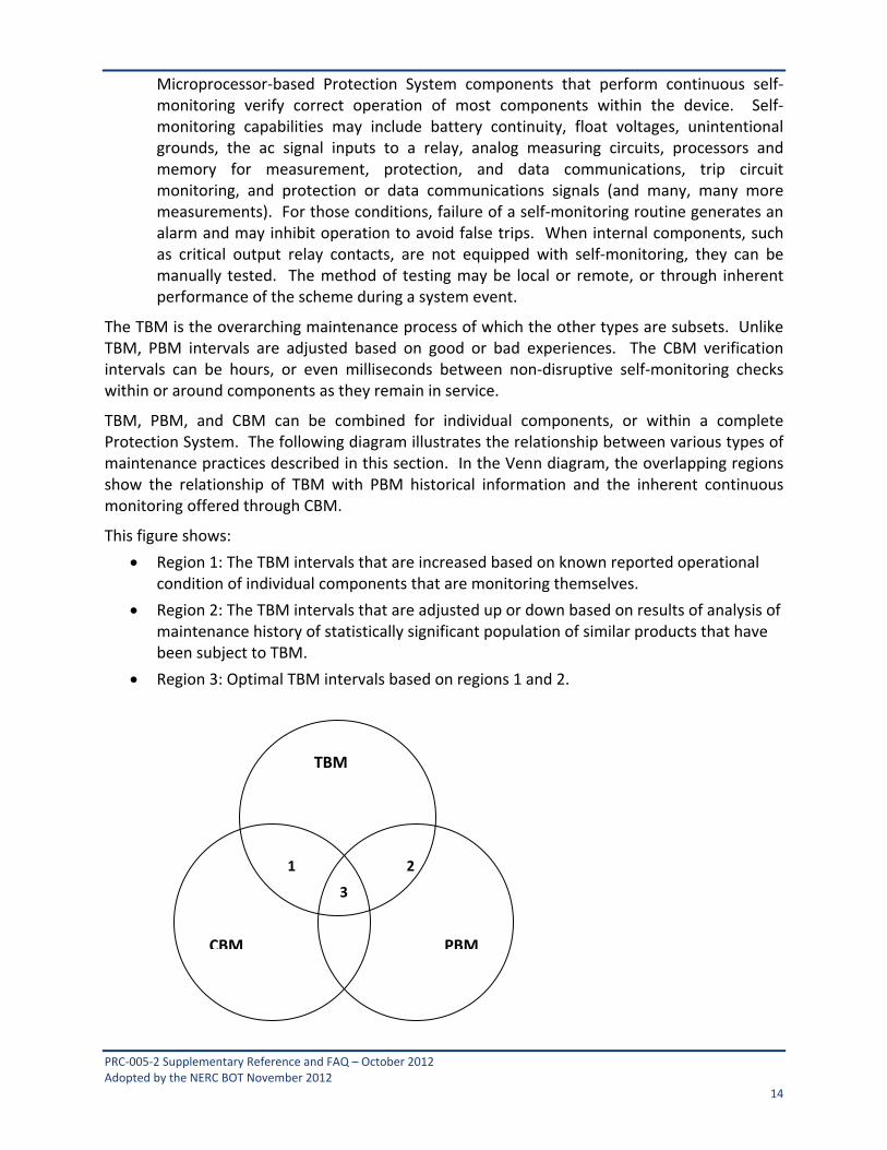
TBM, PBM, and CBM can be combined for individual components, or within a complete Protection System. The following diagram illustrates the relationship between various types of maintenance practices described in this section. In the Venn diagram, the overlapping regions show the relationship of TBM with PBM historical information and the inherent continuous monitoring offered through CBM.
This figure shows:
Region 1: The TBM intervals that are increased based on known reported operational condition of individual components that are monitoring themselves.
Region 2: The TBM intervals that are adjusted up or down based on results of analysis of maintenance history of statistically significant population of similar products that have been subject to TBM.
Region 3: Optimal TBM intervals based on regions 1 and 2.
TBM
PBMCBM
3
21

PRC‐005‐2 Supplementary Reference and FAQ – October 2012 Adopted by the NERC BOT November 2012 15
Relationship of time‐based maintenance types
5.1.1 Frequently Asked Questions:
The standard seems very complicated, and is difficult to understand. Can it be simplified?
Because the standard is establishing parameters for condition‐based Maintenance (R1) and Performance‐Based Maintenance (R2), in addition to simple time‐based Maintenance, it does appear to be complicated. At its simplest, an entity needs to ONLY perform time‐based maintenance according to the unmonitored rows of the Tables. If an entity then wishes to take advantage of monitoring on its Protection System components and its available lengthened time intervals, then it may, as long as the component has the listed monitoring attributes. If an entity wishes to use historical performance of its Protection System components to perform Performance‐Based Maintenance, then R2 applies.
Please see the following diagram, which provides a “flow chart” of the standard.
We have an electromechanical (unmonitored) relay that has a trip output to a lockout relay (unmonitored) which trips our transformer off-line by tripping the transformer’s high-side and low-side circuit breakers. What testing must be done for this system?
PRC‐005‐2 Supplementary Reference and FAQ – October 2012 Adopted by the NERC BOT November 2012 16
This system is made up of components that are all unmonitored. Assuming a time‐based Protection System maintenance program schedule (as opposed to a Performance‐Based maintenance program), each component must be maintained per the most frequent hands‐on activities listed in the Tables.
5.2 Extending Time-Based Maintenance All maintenance is fundamentally time‐based. Default time‐based intervals are commonly established to assure proper functioning of each component of the Protection System, when data on the reliability of the components is not available other than observations from time‐based maintenance. The following factors may influence the established default intervals:
If continuous indication of the functional condition of a component is available (from relays or chargers or any self‐monitoring device), then the intervals may be extended, or manual testing may be eliminated. This is referred to as condition‐based maintenance or CBM. CBM is valid only for precisely the components subject to monitoring. In the case of microprocessor‐based relays, self‐monitoring may not include automated diagnostics of every component within a microprocessor.
Previous maintenance history for a group of components of a common type may indicate that the maintenance intervals can be extended, while still achieving the desired level of performance. This is referred to as Performance‐Based Maintenance, or PBM. It is also sometimes referred to as reliability‐centered maintenance, or RCM; but PBM is used in this document.
Observed proper operation of a component may be regarded as a maintenance verification of the respective component or element in a microprocessor‐based device. For such an observation, the maintenance interval may be reset only to the degree that can be verified by data available on the operation. For example, the trip of an electromechanical relay for a Fault verifies the trip contact and trip path, but only through the relays in series that actually operated; one operation of this relay cannot verify correct calibration.
Excessive maintenance can actually decrease the reliability of the component or system. It is not unusual to cause failure of a component by removing it from service and restoring it. The improper application of test signals may cause failure of a component. For example, in electromechanical overcurrent relays, test currents have been known to destroy convolution springs.
In addition, maintenance usually takes the component out of service, during which time it is not able to perform its function. Cutout switch failures, or failure to restore switch position, commonly lead to protection failures.
5.2.1 Frequently Asked Questions:
If I show the protective device out of service while it is being repaired, then can I add it back as a new protective device when it returns? If not, my relay testing history would show that I was out of compliance for the last maintenance cycle.

PRC‐005‐2 Supplementary Reference and FAQ – October 2012 Adopted by the NERC BOT November 2012 17
The maintenance and testing requirements (R5) (in essence) state “…shall demonstrate efforts to correct any identified Unresolved Maintenance Issues.” The type of corrective activity is not stated; however it could include repairs or replacements.
Your documentation requirements will increase, of course, to demonstrate that your device tested bad and had corrective actions initiated. Your regional entity could very well ask for documentation showing status of your corrective actions.
PRC‐005‐2 Supplementary Reference and FAQ – October 2012 Adopted by the NERC BOT November 2012 18
6. Condition-Based Maintenance (CBM) Programs Condition‐based maintenance is the process of gathering and monitoring the information available from modern microprocessor‐based relays and other intelligent electronic devices (IEDs) that monitor Protection System elements. These devices generate monitoring information during normal operation, and the information can be assessed at a convenient location remote from the substation. The information from these relays and IEDs is divided into two basic types:
1. Information can come from background self‐monitoring processes, programmed by the manufacturer, or by the user in device logic settings. The results are presented by alarm contacts or points, front panel indications, and by data communications messages.
2. Information can come from event logs, captured files, and/or oscillographic records for Faults and Disturbances, metered values, and binary input status reports. Some of these are available on the device front panel display, but may be available via data communications ports. Large files of Fault information can only be retrieved via data communications. These results comprise a mass of data that must be further analyzed for evidence of the operational condition of the Protection System.
Using these two types of information, the user can develop an effective maintenance program carried out mostly from a central location remote from the substation. This approach offers the following advantages:
Non‐invasive Maintenance: The system is kept in its normal operating state, without human intervention for checking. This reduces risk of damage, or risk of leaving the system in an inoperable state after a manual test. Experience has shown that keeping human hands away from equipment known to be working correctly enhances reliability.
Virtually Continuous Monitoring: CBM will report many hardware failure problems for repair within seconds or minutes of when they happen. This reduces the percentage of problems that are discovered through incorrect relaying performance. By contrast, a hardware failure discovered by TBM may have been there for much of the time interval between tests, and there is a good chance that some devices will show health problems by incorrect operation before being caught in the next test round. The frequent or continuous nature of CBM makes the effective verification interval far shorter than any required TBM maximum interval. To use the extended time intervals available through Condition Based Maintenance, simply look for the rows in the Tables that refer to monitored items.
6.1 Frequently Asked Questions:
My microprocessor relays and dc circuit alarms are contained on relay panels in a 24‐hour attended control room. Does this qualify as an extended time interval condition‐based (monitored) system?
Yes, provided the station attendant (plant operator, etc.) monitors the alarms and other indications (comparable to the monitoring attributes) and reports them within the given time limits that are stated in the criteria of the Tables.

PRC‐005‐2 Supplementary Reference and FAQ – October 2012 Adopted by the NERC BOT November 2012 19
When documenting the basis for inclusion of components into the appropriate levels of monitoring, as per Requirement R1 (Part 1.4) of the standard, is it necessary to provide this documentation about the device by listing of every component and the specific monitoring attributes of each device?
No. While maintaining this documentation on the device level would certainly be permissible, it is not necessary. Global statements can be made to document appropriate levels of monitoring for the entire population of a component type or portion thereof.
For example, it would be permissible to document the conclusion that all BES substation dc supply battery chargers are monitored by stating the following within the program description:
“All substation dc supply battery chargers are considered monitored and subject to the rows for monitored equipment of Table 1‐4 requirements, as all substation dc supply battery chargers are equipped with dc voltage alarms and ground detection alarms that are sent to the manned control center.”
Similarly, it would be acceptable to use a combination of a global statement and a device‐level list of exclusions. Example:
“Except as noted below, all substation dc supply battery chargers are considered monitored and subject to the rows for monitored equipment of Table 1‐4 requirements, as all substation dc supply battery chargers are equipped with dc voltage alarms and ground detection alarms that are sent to the manned control center. The dc supply battery chargers of Substation X, Substation Y, and Substation Z are considered unmonitored and subject to the rows for unmonitored equipment in Table 1‐4 requirements, as they are not equipped with ground detection capability.”
Regardless whether this documentation is provided by device listing of monitoring attributes, by global statements of the monitoring attributes of an entire population of component types, or by some combination of these methods, it should be noted that auditors may request supporting drawings or other documentation necessary to validate the inclusion of the device(s) within the appropriate level of monitoring. This supporting background information need not be maintained within the program document structure, but should be retrievable if requested by an auditor.

PRC‐005‐2 Supplementary Reference and FAQ – October 2012 Adopted by the NERC BOT November 2012 20
7. Time-Based Versus Condition-Based Maintenance Time‐based and condition‐based (or monitored) maintenance programs are both acceptable, if implemented according to technically sound requirements. Practical programs can employ a combination of time‐based and condition‐based maintenance. The standard requirements introduce the concept of optionally using condition monitoring as a documented element of a maintenance program.
The Federal Energy Regulatory Commission (FERC), in its Order Number 693 Final Rule, dated March 16, 2007 (18 CFR Part 40, Docket No. RM06‐16‐000) on Mandatory Reliability Standards for the Bulk‐Power System, directed NERC to submit a modification to PRC‐005‐1 that includes a requirement that maintenance and testing of a Protection System must be carried out within a maximum allowable interval that is appropriate to the type of the Protection System and its impact on the reliability of the Bulk Power System. Accordingly, this Supplementary Reference Paper refers to the specific maximum allowable intervals in PRC‐005‐2. The defined time limits allow for longer time intervals if the maintained component is monitored.
A key feature of condition‐based monitoring is that it effectively reduces the time delay between the moment of a protection failure and time the Protection System owner knows about it, for the monitored segments of the Protection System. In some cases, the verification is practically continuous ‐ the time interval between verifications is minutes or seconds. Thus, technically sound, condition‐based verification, meets the verification requirements of the FERC order even more effectively than the strictly time‐based tests of the same system components.
The result is that:
This NERC standard permits utilities to use a technically sound approach and to take advantage of remote monitoring, data analysis, and control capabilities of modern Protection Systems to reduce the need for periodic site visits and invasive testing of components by on‐site technicians. This periodic testing must be conducted within the maximum time intervals specified in Tables 1‐1 through 1‐5 and Table 2 of PRC‐005‐2.
7.1 Frequently Asked Questions:
What is a Calendar Year?
Calendar Year ‐ January 1 through December 31 of any year. As an example, if an event occurred on June 17, 2009 and is on a “One Calendar Year Interval,” the next event would have to occur on or before December 31, 2010.
Please provide an example of “4 Calendar Months”.
If a maintenance activity is described as being needed every four Calendar Months then it is performed in a (given) month and due again four months later. For example a battery bank is inspected in month number 1 then it is due again before the end of the month number5. And specifically consider that you perform your battery inspection on January 3, 2010 then it must be inspected again before the end of May. Another example could be that a four‐month inspection was performed in January is due in May, but if performed in March (instead of May)
PRC‐005‐2 Supplementary Reference and FAQ – October 2012 Adopted by the NERC BOT November 2012 21
would still be due four months later therefore the activity is due again July. Basically every “four Calendar Months” means to add four months from the last time the activity was performed.
Please provide an example of the unmonitored versus other levels of monitoring available?
An unmonitored Protection System has no monitoring and alarm circuits on the Protection System components. A Protection System component that has monitoring attributes but no alarm output connected is considered to be unmonitored.
A monitored Protection System or an individual monitored component of a Protection System has monitoring and alarm circuits on the Protection System components. The alarm circuits must alert, within 24 hours, a location wherein corrective action can be initiated. This location might be, but is not limited to, an Operations Center, Dispatch Office, Maintenance Center or even a portable SCADA system.
There can be a combination of monitored and unmonitored Protection Systems within any given scheme, substation or plant; there can also be a combination of monitored and unmonitored components within any given Protection System.
Example #1: A combination of monitored and unmonitored components within a given Protection System might be:
A microprocessor relay with an internal alarm connected to SCADA to alert 24‐hr staffed operations center; it has internal self diagnosis and alarming. (monitored)
Instrumentation transformers, with no monitoring, connected as inputs to that relay. (unmonitored)
A vented Lead‐Acid battery with a low voltage alarm for the station dc supply voltage and an unintentional grounds detection alarm connected to SCADA. (monitoring varies)
A circuit breaker with a trip coil, and the trip circuit is not monitored. (unmonitored)
Given the particular components and conditions, and using Table 1 and Table 2, the particular components have maximum activity intervals of:
Every four calendar months, inspect:
Electrolyte level (station dc supply voltage and unintentional ground detection is being maintained more frequently by the monitoring system).
Every 18 calendar months, verify/inspect the following:
Battery bank ohmic values to station battery baseline (if performance tests are not opted)
Battery charger float voltage
Battery rack integrity
Cell condition of all individual battery cells (where visible)
Battery continuity
Battery terminal connection resistance
Battery cell‐to‐cell resistance (where available to measure)

PRC‐005‐2 Supplementary Reference and FAQ – October 2012 Adopted by the NERC BOT November 2012 22
Every six calendar years, perform/verify the following:
Battery performance test (if internal ohmic tests or other measurements indicative of battery performance are not opted)
Verify that each trip coil is able to operate the circuit breaker, interrupting device, or mitigating device
For electromechanical lock‐out relays, electrical operation of electromechanical trip
Every 12 calendar years, verify the following:
Microprocessor relay settings are as specified
Operation of the microprocessor’s relay inputs and outputs that are essential to proper functioning of the Protection System
Acceptable measurement of power System input values seen by the microprocessor protective relay
Verify that current and voltage signal values are provided to the protective relays
Protection System component monitoring for the battery system signals are conveyed to a location where corrective action can be initiated
The microprocessor relay alarm signals are conveyed to a location where corrective action can be initiated
Verify all trip paths in the control circuitry associated with protective functions through the trip coil(s) of the circuit breakers or other interrupting devices
Auxiliary outputs that are in the trip path shall be maintained as detailed in Table 1‐5 of the standard under the ‘Unmonitored Control Circuitry Associated with Protective Functions" section’
Auxiliary outputs not in a trip path (i.e., annunciation or DME input) are not required, by this standard, to be checked
Example #2: A combination of monitored and unmonitored components within a given Protection System might be:
A microprocessor relay with integral alarm that is not connected to SCADA. (unmonitored)
Current and voltage signal values, with no monitoring, connected as inputs to that relay. (unmonitored)
A vented lead‐acid battery with a low voltage alarm for the station dc supply voltage and an unintentional grounds detection alarm connected to SCADA. (monitoring varies)
A circuit breaker with a trip coil, with no circuits monitored. (unmonitored)
Given the particular components and conditions, and using the Table 1 (Maximum Allowable Testing Intervals and Maintenance Activities) and Table 2 (Alarming Paths and Monitoring), the particular components have maximum activity intervals of:
Every four calendar months, inspect:
PRC‐005‐2 Supplementary Reference and FAQ – October 2012 Adopted by the NERC BOT November 2012 23
Electrolyte level (station dc supply voltage and unintentional ground detection is being maintained more frequently by the monitoring system)
Every 18 calendar months, verify/inspect the following:
Battery bank trending of ohmic values or other measurements indicative of battery performance to station battery baseline (if performance tests are not opted)
Battery charger float voltage
Battery rack integrity
Cell condition of all individual battery cells (where visible)
Battery continuity
Battery terminal connection resistance
Battery cell‐to‐cell resistance (where available to measure)
Every six calendar years, verify/perform the following:
Verify operation of the relay inputs and outputs that are essential to proper functioning of the Protection System
Verify acceptable measurement of power system input values as seen by the relays
Verify that each trip coil is able to operate the circuit breaker, interrupting device, or mitigating device
For electromechanical lock‐out relays, electrical operation of electromechanical trip
Battery performance test (if internal ohmic tests are not opted)
Every 12 calendar years, verify the following:
Current and voltage signal values are provided to the protective relays
Protection System component monitoring for the battery system signals are conveyed to a location where corrective action can be initiated
All trip paths in the control circuitry associated with protective functions through the trip coil(s) of the circuit breakers or other interrupting devices
Auxiliary outputs that are in the trip path shall be maintained, as detailed in Table 1‐5 of the standard under the Unmonitored Control Circuitry Associated with Protective Functions" section
Auxiliary outputs not in a trip path (i.e., annunciation or DME input) are not required, by this standard, to be checked
Example #3: A combination of monitored and unmonitored components within a given Protection System might be:
A microprocessor relay with alarm connected to SCADA to alert 24‐hr staffed operations center; it has internal self diagnosis and alarms. (monitored)
Current and voltage signal values, with monitoring, connected as inputs to that relay (monitored)

PRC‐005‐2 Supplementary Reference and FAQ – October 2012 Adopted by the NERC BOT November 2012 24
Vented Lead‐Acid battery without any alarms connected to SCADA (unmonitored)
Circuit breaker with a trip coil, with no circuits monitored (unmonitored)
Given the particular components, conditions, and using the Table 1 (Maximum Allowable Testing Intervals and Maintenance Activities) and Table 2 (Alarming Paths and Monitoring), the particular components shall have maximum activity intervals of:
Every four calendar months, verify/inspect the following:
Station dc supply voltage
For unintentional grounds
Electrolyte level
Every 18 calendar months, verify/inspect the following:
Battery bank trending of ohmic values or other measurements indicative of battery performance to station battery baseline (if performance tests are not opted)
Battery charger float voltage
Battery rack integrity
Battery continuity
Battery terminal connection resistance
Battery cell‐to‐cell resistance (where available to measure)
Condition of all individual battery cells (where visible)
Every six calendar years, perform/verify the following:
Battery performance test (if internal ohmic tests or other measurements indicative of battery performance are not opted)
Verify that each trip coil is able to operate the circuit breaker, interrupting device, or mitigating device
For electromechanical lock‐out relays, electrical operation of electromechanical trip
Every 12 calendar years, verify the following:
The microprocessor relay alarm signals are conveyed to a location where corrective action can be taken
Microprocessor relay settings are as specified
Operation of the microprocessor’s relay inputs and outputs that are essential to proper functioning of the Protection System
Acceptable measurement of power system input values seen by the microprocessor protective relay
Verify all trip paths in the control circuitry associated with protective functions through the trip coil(s) of the circuit breakers or other interrupting devices

PRC‐005‐2 Supplementary Reference and FAQ – October 2012 Adopted by the NERC BOT November 2012 25
Auxiliary outputs that are in the trip path shall be maintained, as detailed in Table 1‐5 of the standard under the Unmonitored Control Circuitry Associated with Protective Functions section
Auxiliary outputs not in a trip path (i.e. annunciation or DME input) are not required, by this standard, to be checked
Why do components have different maintenance activities and intervals if they are monitored?
The intent behind different activities and intervals for monitored equipment is to allow less frequent manual intervention when more information is known about the condition of Protection System components. Condition‐Based Maintenance is a valuable asset to improve reliability.
Can all components in a Protection System be monitored?
No. For some components in a Protection System, monitoring will not be relevant. For example, a battery will always need some kind of inspection.
We have a 30-year-old oil circuit breaker with a red indicating lamp on the substation relay panel that is illuminated only if there is continuity through the breaker trip coil. There is no SCADA monitor or relay monitor of this trip coil. The line protection relay package that trips this circuit breaker is a microprocessor relay that has an integral alarm relay that will assert on a number of conditions that includes a loss of power to the relay. This alarm contact connects to our SCADA system and alerts our 24-hour operations center of relay trouble when the alarm contact closes. This microprocessor relay trips the circuit breaker only and does not monitor trip coil continuity or other things such as trip current. Are the components monitored or not? How often must I perform maintenance?
The protective relay is monitored and can be maintained every 12 years, or when an Unresolved Maintenance Issue arises. The control circuitry can be maintained every 12 years. The circuit breaker trip coil(s) has to be electrically operated at least once every six years.
What is a mitigating device?
A mitigating device is the device that acts to respond as directed by a Special Protection System. It may be a breaker, valve, distributed control system, or any variety of other devices.

PRC‐005‐2 Supplementary Reference and FAQ – October 2012 Adopted by the NERC BOT November 2012 26
8. Maximum Allowable Verification Intervals
The maximum allowable testing intervals and maintenance activities show how CBM with newer device types can reduce the need for many of the tests and site visits that older Protection System components require. As explained below, there are some sections of the Protection System that monitoring or data analysis may not verify. Verifying these sections of the Protection Systems requires some persistent TBM activity in the maintenance program. However, some of this TBM can be carried out remotely ‐ for example, exercising a circuit breaker through the relay tripping circuits using the relay remote control capabilities can be used to verify function of one tripping path and proper trip coil operation, if there has been no Fault or routine operation to demonstrate performance of relay tripping circuits.
8.1 Maintenance Tests Periodic maintenance testing is performed to ensure that the protection and control system is operating correctly after a time period of field installation. These tests may be used to ensure that individual components are still operating within acceptable performance parameters ‐ this type of test is needed for components susceptible to degraded or changing characteristics due to aging and wear. Full system performance tests may be used to confirm that the total Protection System functions from measurement of power system values, to properly identifying Fault characteristics, to the operation of the interrupting devices.
8.1.1 Table of Maximum Allowable Verification Intervals Table 1 (collectively known as Table 1, individually called out as Tables 1‐1 through 1‐5), Table 2 and Table 3 in the standard specify maximum allowable verification intervals for various generations of Protection Systems and categories of equipment that comprise Protection Systems. The right column indicates maintenance activities required for each category.
The types of components are illustrated in Figures 1 and 2 at the end of this paper. Figure 1 shows an example of telecommunications‐assisted transmission Protection System comprising substation equipment at each terminal and a telecommunications channel for relaying between the two substations. Figure 2 shows an example of a generation Protection System. The various sub‐systems of a Protection System that need to be verified are shown.
Non‐distributed UFLS, UVLS, and SPS are additional categories of Table 1 that are not illustrated in these figures. Non‐distributed UFLS, UVLS and SPS all use identical equipment as Protection Systems in the performance of their functions; and, therefore, have the same maintenance needs.
Distributed UFLS and UVLS Systems, which use local sensing on the distribution System and trip co‐located non‐BES interrupting devices, are addressed in Table 3 with reduced maintenance activities.
While it is easy to associate protective relays to multiple levels of monitoring, it is also true that most of the components that can make up a Protection System can also have technological advancements that place them into higher levels of monitoring.
To use the Maintenance Activities and Intervals Tables from PRC‐005‐2:
PRC‐005‐2 Supplementary Reference and FAQ – October 2012 Adopted by the NERC BOT November 2012 27
First find the Table associated with your component. The tables are arranged in the order of mention in the definition of Protection System;
o Table 1‐1 is for protective relays,
o Table 1‐2 is for the associated communications systems,
o Table 1‐3 is for current and voltage sensing devices,
o Table 1‐4 is for station dc supply and
o Table 1‐5 is for control circuits.
o Table 2, is for alarms; this was broken out to simplify the other tables.
o Table 3 is for components which make‐up distributed UFLS and UVLS Systems.
Next look within that table for your device and its degree of monitoring. The Tables have different hands‐on maintenance activities prescribed depending upon the degree to which you monitor your equipment. Find the maintenance activity that applies to the monitoring level that you have on your piece of equipment.
This Maintenance activity is the minimum maintenance activity that must be documented.
If your Performance‐Based Maintenance (PBM) plan requires more activities, then you must perform and document to this higher standard. (Note that this does not apply unless you utilize PBM.)
After the maintenance activity is known, check the maximum maintenance interval; this time is the maximum time allowed between hands‐on maintenance activity cycles of this component.
If your Performance‐Based Maintenance plan requires activities more often than the Tables maximum, then you must perform and document those activities to your more stringent standard. (Note that this does not apply unless you utilize PBM.)
Any given component of a Protection System can be determined to have a degree of monitoring that may be different from another component within that same Protection System. For example, in a given Protection System it is possible for an entity to have a monitored protective relay and an unmonitored associated communications system; this combination would require hands‐on maintenance activity on the relay at least once every 12 years and attention paid to the communications system as often as every four months.
An entity does not have to utilize the extended time intervals made available by this use of condition‐based monitoring. An easy choice to make is to simply utilize the unmonitored level of maintenance made available on each of the five Tables. While the maintenance activities resulting from this choice would require more maintenance man‐hours, the maintenance requirements may be simpler to document and the resulting maintenance plans may be easier to create.
For each Protection System component, Table 1 shows maximum allowable testing intervals for the various degrees of monitoring. These degrees of monitoring, or levels, range from the legacy unmonitored through a system that is more comprehensively monitored.

PRC‐005‐2 Supplementary Reference and FAQ – October 2012 Adopted by the NERC BOT November 2012 28
It has been noted here that an entity may have a PSMP that is more stringent than PRC‐005‐2. There may be any number of reasons that an entity chooses a more stringent plan than the minimums prescribed within PRC‐005‐2, most notable of which is an entity using performance based maintenance methodology. If an entity has a Performance‐Based Maintenance program, then that plan must be followed, even if the plan proves to be more stringent than the minimums laid out in the Tables.
8.1.2 Additional Notes for Tables 1-1 through 1-5 and Table 3 1. For electromechanical relays, adjustment is required to bring measurement accuracy
within the tolerance needed by the asset owner. Microprocessor relays with no remote monitoring of alarm contacts, etc, are unmonitored relays and need to be verified within the Table interval as other unmonitored relays but may be verified as functional by means other than testing by simulated inputs.
2. Microprocessor relays typically are specified by manufacturers as not requiring calibration, but acceptable measurement of power system input values must be verified (verification of the Analog to Digital [A/D] converters) within the Table intervals. The integrity of the digital inputs and outputs that are used as protective functions must be verified within the Table intervals.
3. Any Phasor Measurement Unit (PMU) function whose output is used in a Protection System or SPS (as opposed to a monitoring task) must be verified as a component in a Protection System.
4. In addition to verifying the circuitry that supplies dc to the Protection System, the owner must maintain the station dc supply. The most widespread station dc supply is the station battery and charger. Unlike most Protection System components, physical inspection of station batteries for signs of component failure, reduced performance, and degradation are required to ensure that the station battery is reliable enough to deliver dc power when required. IEEE Standards 450, 1188, and 1106 for vented lead‐acid, valve‐regulated lead‐acid, and nickel‐cadmium batteries, respectively (which are the most commonly used substation batteries on the NERC BES) have been developed as an important reference source of maintenance recommendations. The Protection System owner might want to follow the guidelines in the applicable IEEE recommended practices for battery maintenance and testing, especially if the battery in question is used for application requirements in addition to the protection and control demands covered under this standard. However, the Standard Drafting Team has tailored the battery maintenance and testing guidelines in PRC‐005‐2 for the Protection System owner which are application specific for the BES Facilities. While the IEEE recommendations are all encompassing, PRC‐005‐2 is a more economical approach while addressing the reliability requirements of the BES.
5. Aggregated small entities might distribute the testing of the population of UFLS/UVLS systems, and large entities will usually maintain a portion of these systems in any given year. Additionally, if relatively small quantities of such systems do not perform properly, it will not affect the integrity of the overall program. Thus, these distributed systems have decreased requirements as compared to other Protection Systems.
PRC‐005‐2 Supplementary Reference and FAQ – October 2012 Adopted by the NERC BOT November 2012 29
6. Voltage & current sensing device circuit input connections to the Protection System relays can be verified by (but not limited to) comparison of measured values on live circuits or by using test currents and voltages on equipment out of service for maintenance. The verification process can be automated or manual. The values should be verified to be as expected (phase value and phase relationships are both equally important to verify).
7. “End‐to‐end test,” as used in this Supplementary Reference, is any testing procedure that creates a remote input to the local communications‐assisted trip scheme. While this can be interpreted as a GPS‐type functional test, it is not limited to testing via GPS. Any remote scheme manipulation that can cause action at the local trip path can be used to functionally‐test the dc control circuitry. A documented Real‐time trip of any given trip path is acceptable in lieu of a functional trip test. It is possible, with sufficient monitoring, to be able to verify each and every parallel trip path that participated in any given dc control circuit trip. Or another possible solution is that a single trip path from a single monitored relay can be verified to be the trip path that successfully tripped during a Real‐time operation. The variations are only limited by the degree of engineering and monitoring that an entity desires to pursue.
8. A/D verification may use relay front panel value displays, or values gathered via data communications. Groupings of other measurements (such as vector summation of bus feeder currents) can be used for comparison if calibration requirements assure acceptable measurement of power system input values.
9. Notes 1‐8 attempt to describe some testing activities; they do not represent the only methods to achieve these activities, but rather some possible methods. Technological advances, ingenuity and/or industry accepted techniques can all be used to satisfy maintenance activity requirements; the standard is technology‐ and method‐neutral in most cases.
8.1.3 Frequently Asked Questions: What is meant by “Verify that settings are as specified” maintenance activity in Table 1-1?
Verification of settings is an activity directed mostly towards microprocessor‐ based relays. For relay maintenance departments that choose to test microprocessor‐based relays in the same manner as electromechanical relays are tested, the testing process sometimes requires that some specific functions be disabled. Later tests might enable the functions previously disabled, but perhaps still other functions or logic statements were then masked out. It is imperative that, when the relay is placed into service, the settings in the relay be the settings that were intended to be in that relay or as the standard states “…settings are as specified.”
Many of the microprocessor‐ based relays available today have software tools which provide this functionality and generate reports for this purpose.
For evidence or documentation of this requirement, a simple recorded acknowledgement that the settings were checked to be as specified is sufficient.
The drafting team was careful not to require “…that the relay settings be correct…” because it was believed that this might then place a burden of proof that the specified settings would result in the correct intended operation of the interrupting device. While that is a noble

PRC‐005‐2 Supplementary Reference and FAQ – October 2012 Adopted by the NERC BOT November 2012 30
intention, the measurable proof of such a requirement is immense. The intent is that settings of the component be as specified at the conclusion of maintenance activities, whether those settings may have “drifted” since the prior maintenance or whether changes were made as part of the testing process.
Are electromechanical relays included in the “Verify that settings are as specified” maintenance activity in Table 1-1?
Verification of settings is an activity directed towards the application of protection related functions of microprocessor based relays. Electromechanical relays require calibration verification by voltage and/or current injection; and, thus, the settings are verified during calibration activity. In the example of a time‐overcurrent relay, a minor deviation in time dial, versus the settings, may be acceptable, as long as the relay calibration is within accepted tolerances at the injected current amplitudes. A major deviation may require further investigation, as it could indicate a problem with the relay or an incorrect relay style for the application.
The verification of phase current and voltage measurements by comparison to other quantities seems reasonable. How, though, can I verify residual or neutral currents, or 3V0 voltages, by comparison, when my system is closely balanced?
Since these inputs are verified at commissioning, maintenance verification requires ensuring that phase quantities are as expected and that 3IO and 3VO quantities appear equal to or close to 0.
These quantities also may be verified by use of oscillographic records for connected microprocessor relays as recorded during system Disturbances. Such records may compare to similar values recorded at other locations by other microprocessor relays for the same event, or compared to expected values (from short circuit studies) for known Fault locations.
What does this Standard require for testing an auxiliary tripping relay?
Table 1 and Table 3 requires that a trip test must verify that the auxiliary tripping relay(s) and/or lockout relay(s) which are directly in a trip path from the protective relay to the interrupting device trip coil operate(s) electrically. Auxiliary outputs not in a trip path (i.e. annunciation or DME input) are not required, by this standard, to be checked.
Do I have to perform a full end-to-end test of a Special Protection System?
No. All portions of the SPS need to be maintained, and the portions must overlap, but the overall SPS does not need to have a single end‐to‐end test. In other words it may be tested in piecemeal fashion provided all of the pieces are verified.
What about SPS interfaces between different entities or owners?
As in all of the Protection System requirements, SPS segments can be tested individually, thus minimizing the need to accommodate complex maintenance schedules.
What do I have to do if I am using a phasor measurement unit (PMU) as part of a Protection System or Special Protection System?
Any Phasor Measurement Unit (PMU) function whose output is used in a Protection System or Special Protection System (as opposed to a monitoring task) must be verified as a component in a Protection System.
PRC‐005‐2 Supplementary Reference and FAQ – October 2012 Adopted by the NERC BOT November 2012 31
How do I maintain a Special Protection System or relay sensing for non-distributed UFLS or UVLS Systems?
Since components of the SPS, UFLS and UVLS are the same types of components as those in Protection Systems, then these components should be maintained like similar components used for other Protection System functions. In many cases the devices for SPS, UFLS and UVLS are also used for other protective functions. The same maintenance activities apply with the exception that distributed systems (UFLS and UVLS) have fewer dc supply and control circuitry maintenance activity requirements.
For the testing of the output action, verification may be by breaker tripping, but may be verified in overlapping segments. For example, an SPS that trips a remote circuit breaker might be tested by testing the various parts of the scheme in overlapping segments. Another method is to document the Real‐time tripping of an SPS scheme should that occur. Forced trip tests of circuit breakers (etc) that are a part of distributed UFLS or UVLS schemes are not required.
The established maximum allowable intervals do not align well with the scheduled outages for my power plant. Can I extend the maintenance to the next scheduled outage following the established maximum interval?
No. You must complete your maintenance within the established maximum allowable intervals in order to be compliant. You will need to schedule your maintenance during available outages to complete your maintenance as required, even if it means that you may do protective relay maintenance more frequently than the maximum allowable intervals. The maintenance intervals were selected with typical plant outages, among other things, in mind.
If I am unable to complete the maintenance, as required, due to a major natural disaster (hurricane, earthquake, etc.), how will this affect my compliance with this standard?
The Sanction Guidelines of the North American Electric Reliability Corporation, effective January 15, 2008, provides that the Compliance Monitor will consider extenuating circumstances when considering any sanctions.
What if my observed testing results show a high incidence of out-of-tolerance relays; or, even worse, I am experiencing numerous relay Misoperations due to the relays being out-of-tolerance?
The established maximum time intervals are mandatory only as a not‐to‐exceed limitation. The establishment of a maximum is measurable. But any entity can choose to test some or all of their Protection System components more frequently (or to express it differently, exceed the minimum requirements of the standard). Particularly if you find that the maximum intervals in the standard do not achieve your expected level of performance, it is understandable that you would maintain the related equipment more frequently. A high incidence of relay Misoperations is in no one’s best interest.
We believe that the four-month interval between inspections is unneccessary. Why can we not perform these inspections twice per year?
The Standard Drafting Team, through the comment process, has discovered that routine monthly inspections are not the norm. To align routine station inspections with other important inspections, the four‐month interval was chosen. In lieu of station visits, many activities can be accomplished with automated monitoring and alarming.
PRC‐005‐2 Supplementary Reference and FAQ – October 2012 Adopted by the NERC BOT November 2012 32
Our maintenance plan calls for us to perform routine protective relay tests every 3 years. If we are unable to achieve this schedule, but we are able to complete the procedures in less than the maximum time interval ,then are we in or out of compliance?
According to R3, if you have a time‐based maintenance program, then you will be in violation of the standard only if you exceed the maximum maintenance intervals prescribed in the Tables. According to R4, if your device in question is part of a Performance‐Based Maintenance program, then you will be in violation of the standard if you fail to meet your PSMP, even if you do not exceed the maximum maintenance intervals prescribed in the Tables. The intervals in the Tables are associated with TBM and CBM; Attachment A is associated with PBM.
Please provide a sample list of devices or systems that must be verified in a generator, generator step-up transformer, generator connected station service or generator connected excitation transformer to meet the requirements of this maintenance standard.
Examples of typical devices and systems that may directly trip the generator, or trip through a lockout relay, may include, but are not necessarily limited to:
Fault protective functions, including distance functions, voltage‐restrained overcurrent functions, or voltage‐controlled overcurrent functions
Loss‐of‐field relays
Volts‐per‐hertz relays
Negative sequence overcurrent relays
Over voltage and under voltage protection relays
Stator‐ground relays
Communications‐based Protection Systems such as transfer‐trip systems
Generator differential relays
Reverse power relays
Frequency relays
Out‐of‐step relays
Inadvertent energization protection
Breaker failure protection
For generator step‐up, generator‐connected station service transformers, or generator connected excitation transformers, operation of any of the following associated protective relays frequently would result in a trip of the generating unit; and, as such, would be included in the program:
Transformer differential relays
Neutral overcurrent relay
Phase overcurrent relays

PRC‐005‐2 Supplementary Reference and FAQ – October 2012 Adopted by the NERC BOT November 2012 33
Relays which trip breakers serving station auxiliary Loads such as pumps, fans, or fuel handling equipment, etc., need not be included in the program, even if the loss of the those Loads could result in a trip of the generating unit. Furthermore, relays which provide protection to secondary unit substation (SUS) or low switchgear transformers and relays protecting other downstream plant electrical distribution system components are not included in the scope of this program, even if a trip of these devices might eventually result in a trip of the generating unit. For example, a thermal overcurrent trip on the motor of a coal‐conveyor belt could eventually lead to the tripping of the generator, but it does not cause the trip.
In the case where a plant does not have a generator connected station service transformer such that it is normally fed from a system connected station service transformer, is it still the drafting team’s intent to exclude the Protection Systems for these system connected auxiliary transformers from scope even when the loss of the normal (system connected) station service transformer will result in a trip of a BES generating Facility?
The SDT does not intend that the system‐connected station service transformers be included in the Applicability. The generator‐connected station service transformers and generator connected excitation transformers are often connected to the generator bus directly without an interposing breaker; thus, the Protection Systems on these transformers will trip the generator as discussed in 4.2.5.1.
What is meant by “verify operation of the relay inputs and outputs that are essential to proper functioning of the Protection System?”
Any input or output (of the relay) that “affects the tripping” of the breaker is included in the scope of I/O of the relay to be verified. By “affects the tripping,” one needs to realize that sometimes there are more inputs and outputs than simply the output to the trip coil. Many important protective functions include things like breaker fail initiation, zone timer initiation and sometimes even 52a/b contact inputs are needed for a protective relay to correctly operate.
Each input should be “picked up” or “turned on and off” and verified as changing state by the microprocessor of the relay. Each output should be “operated” or “closed and opened” from the microprocessor of the relay and the output should be verified to change state on the output terminals of the relay. One possible method of testing inputs of these relays is to “jumper” the needed dc voltage to the input and verify that the relay registered the change of state.
Electromechanical lock‐out relays (86) (used to convey the tripping current to the trip coils) need to be electrically operated to prove the capability of the device to change state. These tests need to be accomplished at least every six years, unless PBM methodology is applied.
The contacts on the 86 or auxiliary tripping relays (94) that change state to pass on the trip current to a breaker trip coil need only be checked every 12 years with the control circuitry.
What is the difference between a distributed UFLS/UVLS and a non-distributed UFLS/UVLS scheme?
A distributed UFLS or UVLS scheme contains individual relays which make independent Load shed decisions based on applied settings and localized voltage and/or current inputs. A distributed scheme may involve an enable/disable contact in the scheme and still be considered a distributed scheme. A non‐distributed UFLS or UVLS scheme involves a system where there is

PRC‐005‐2 Supplementary Reference and FAQ – October 2012 Adopted by the NERC BOT November 2012 34
some type of centralized measurement and Load shed decision being made. A non‐distributed UFLS/UVLS scheme is considered similar to an SPS scheme and falls under Table 1 for maintenance activities and intervals.
8.2 Retention of Records PRC‐005‐1 describes a reporting or auditing cycle of one year and retention of records for three years. However, with a three‐year retention cycle, the records of verification for a Protection System might be discarded before the next verification, leaving no record of what was done if a Misoperation or failure is to be analyzed.
PRC‐005‐2 corrects this by requiring:
The Transmission Owner, Generator Owner, and Distribution Provider shall each retain documentation of the two most recent performances of each distinct maintenance activity for the Protection System components, or to the previous scheduled (on‐site) audit date, whichever is longer.
This requirement assures that the documentation shows that the interval between maintenance cycles correctly meets the maintenance interval limits. The requirement is actually alerting the industry to documentation requirements already implemented by audit teams. Evidence of compliance bookending the interval shows interval accomplished instead of proving only your planned interval.
The SDT is aware that, in some cases, the retention period could be relatively long. But, the retention of documents simply helps to demonstrate compliance.
8.2.1 Frequently Asked Questions:
Please use a specific example to demonstrate the data retention requirements.
The data retention requirements are intended to allow the availability of maintenance records to demonstrate that the time intervals in your maintenance plan were upheld. For example: “Company A” has a maintenance plan that requires its electromechanical protective relays be tested every three calendar years, with a maximum allowed grace period of an additional 18 months. This entity would be required to maintain its records of maintenance of its last two routine scheduled tests. Thus, its test records would have a latest routine test, as well as its previous routine test. The interval between tests is, therefore, provable to an auditor as being within “Company A’s” stated maximum time interval of 4.5 years.
The intent is not to require three test results proving two time intervals, but rather have two test results proving the last interval. The drafting team contends that this minimizes storage requirements, while still having minimum data available to demonstrate compliance with time intervals.
If an entity prefers to utilize Performance‐Based Maintenance, then statistical data may well be retained for extended periods to assist with future adjustments in time intervals.
If an equipment item is replaced, then the entity can restart the maintenance‐time‐interval‐clock if desired; however, the replacement of equipment does not remove any documentation requirements that would have been required to verify compliance with time‐interval requirements. In other words, do not discard maintenance data that goes to verify your work.

PRC‐005‐2 Supplementary Reference and FAQ – October 2012 Adopted by the NERC BOT November 2012 35
The retention of documentation for new and/or replaced equipment is all about proving that the maintenance intervals had been in compliance. For example, a long‐range plan of upgrades might lead an entity to ignore required maintenance; retaining the evidence of prior maintenance that existed before any retirements and upgrades proves compliance with the standard.
What does this Maintenance Standard say about commissioning? Is it necessary to have documentation in your maintenance history of the completion of commission testing?
This standard does not establish requirements for commission testing. Commission testing includes all testing activities necessary to conclude that a Facility has been built in accordance with design. While a thorough commission testing program would include, either directly or indirectly, the verification of all those Protection System attributes addressed by the maintenance activities specified in the Tables of PRC‐005‐2, verification of the adequacy of initial installation necessitates the performance of testing and inspections that go well beyond these routine maintenance activities. For example, commission testing might set baselines for future tests; perform acceptance tests and/or warranty tests; utilize testing methods that are not generally done routinely like staged‐Fault‐tests.
However, many of the Protection System attributes which are verified during commission testing are not subject to age related or service related degradation, and need not be re‐verified within an ongoing maintenance program. Example – it is not necessary to re‐verify correct terminal strip wiring on an ongoing basis.
PRC‐005‐2 assumes that thorough commission testing was performed prior to a Protection System being placed in service. PRC‐005‐2 requires performance of maintenance activities that are deemed necessary to detect and correct plausible age and service related degradation of components, such that a properly built and commission tested Protection System will continue to function as designed over its service life.
It should be noted that commission testing frequently is performed by a different organization than that which is responsible for the ongoing maintenance of the Protection System. Furthermore, the commission testing activities will not necessarily correlate directly with the maintenance activities required by the standard. As such, it is very likely that commission testing records will deviate significantly from maintenance records in both form and content; and, therefore, it is not necessary to maintain commission testing records within the maintenance program documentation.
Notwithstanding the differences in records, an entity would be wise to retain commissioning records to show a maintenance start date. (See below). An entity that requires that their commissioning tests have, at a minimum, the requirements of PRC‐005‐2 would help that entity prove time interval maximums by setting the initial time clock.
How do you determine the initial due date for maintenance?
The initial due date for maintenance should be based upon when a Protection System was tested. Alternatively, an entity may choose to use the date of completion of the commission testing of the Protection System component and the system was placed into service as the starting point in determining its first maintenance due dates. Whichever method is chosen, for

PRC‐005‐2 Supplementary Reference and FAQ – October 2012 Adopted by the NERC BOT November 2012 36
newly installed Protection Systems the components should not be placed into service until minimum maintenance activities have taken place.
It is conceivable that there can be a (substantial) difference in time between the date of testing, as compared to the date placed into service. The use of the “Calendar Year” language can help determine the next due date without too much concern about being non‐compliant for missing test dates by a small amount (provided your dates are not already at the end of a year). However, if there is a substantial amount of time difference between testing and in‐service dates, then the testing date should be followed because it is the degradation of components that is the concern. While accuracy fluctuations may decrease when components are not energized, there are cases when degradation can take place, even though the device is not energized. Minimizing the time between commissioning tests and in‐service dates will help.
If I miss two battery inspections four times out of 100 Protection System components on my transmission system, does that count as 2% or 8% when counting Violation Severity Level (VSL) for R3?
The entity failed to complete its scheduled program on two of its 100 Protection System components, which would equate to 2% for application to the VSL Table for Requirement R3. This VSL is written to compare missed components to total components. In this case two components out of 100 were missed, or 2%.
How do I achieve a “grace period” without being out of compliance?
The objective here is to create a time extension within your own PSMP that still does not violate the maximum time intervals stated in the standard. Remember that the maximum time intervals listed in the Tables cannot be extended.
For the purposes of this example, concentrating on just unmonitored protective relays – Table 1‐1 specifies a maximum time interval (between the mandated maintenance activities) of six calendar years. Your plan must ensure that your unmonitored relays are tested at least once every six calendar years. You could, within your PSMP, require that your unmonitored relays be tested every four calendar years, with a maximum allowable time extension of 18 calendar months. This allows an entity to have deadlines set for the auto‐generation of work orders, but still has the flexibility in scheduling complex work schedules. This also allows for that 18 calendar months to act as a buffer, in effect a grace period within your PSMP, in the event of unforeseen events. You will note that this example of a maintenance plan interval has a planned time of four years; it also has a built‐in time extension allowed within the PSMP, and yet does not exceed the maximum time interval allowed by the standard. So while there are no time extensions allowed beyond the standard, an entity can still have substantial flexibility to maintain their Protection System components.
8.3 Basis for Table 1 Intervals
When developing the original Protection System Maintenance – A Technical Reference in 2007, the SPCTF collected all available data from Regional Entities (REs) on time intervals recommended for maintenance and test programs. The recommendations vary widely in categorization of relays, defined maintenance actions, and time intervals, precluding development of intervals by averaging. The SPCTF also reviewed the 2005 Report [2] of the IEEE Power System Relaying Committee Working Group I‐17 (Transmission Relay System Performance Comparison). Review of the I‐17 report shows data from a small number of

PRC‐005‐2 Supplementary Reference and FAQ – October 2012 Adopted by the NERC BOT November 2012 37
utilities, with no company identification or means of investigating the significance of particular results.
To develop a solid current base of practice, the SPCTF surveyed its members regarding their maintenance intervals for electromechanical and microprocessor relays, and asked the members to also provide definitively‐known data for other entities. The survey represented 470 GW of peak Load, or 4% of the NERC peak Load. Maintenance interval averages were compiled by weighting reported intervals according to the size (based on peak Load) of the reporting utility. Thus, the averages more accurately represent practices for the large populations of Protection Systems used across the NERC regions.
The results of this survey with weighted averaging indicate maintenance intervals of five years for electromechanical or solid state relays, and seven years for unmonitored microprocessor relays.
A number of utilities have extended maintenance intervals for microprocessor relays beyond seven years, based on favorable experience with the particular products they have installed. To provide a technical basis for such extension, the SPCTF authors developed a recommendation of 10 years using the Markov modeling approach from [1], as summarized in Section 8.4. The results of this modeling depend on the completeness of self‐testing or monitoring. Accordingly, this extended interval is allowed by Table 1, only when such relays are monitored as specified in the attributes of monitoring contained in Tables 1‐1 through 1‐5 and Table 2. Monitoring is capable of reporting Protection System health issues that are likely to affect performance within the 10 year time interval between verifications.
It is important to note that, according to modeling results, Protection System availability barely changes as the maintenance interval is varied below the 10‐year mark. Thus, reducing the maintenance interval does not improve Protection System availability. With the assumptions of the model regarding how maintenance is carried out, reducing the maintenance interval actually degrades Protection System availability.
8.4 Basis for Extended Maintenance Intervals for Microprocessor Relays
Table 1 allows maximum verification intervals that are extended based on monitoring level. The industry has experience with self‐monitoring microprocessor relays that leads to the Table 1 value for a monitored relay, as explained in Section 8.3. To develop a basis for the maximum interval for monitored relays in their Protection System Maintenance – A Technical Reference, the SPCTF used the methodology of Reference [1], which specifically addresses optimum routine maintenance intervals. The Markov modeling approach of [1] is judged to be valid for the design and typical failure modes of microprocessor relays.
The SPCTF authors ran test cases of the Markov model to calculate two key probability measures:
Relay Unavailability ‐ the probability that the relay is out of service due to failure or maintenance activity while the power system Element to be protected is in service.
Abnormal Unavailability ‐ the probability that the relay is out of service due to failure or maintenance activity when a Fault occurs, leading to failure to operate for the Fault.
The parameter in the Markov model that defines self‐monitoring capability is ST (for self test). ST = 0 if there is no self‐monitoring; ST = 1 for full monitoring. Practical ST values are estimated

PRC‐005‐2 Supplementary Reference and FAQ – October 2012 Adopted by the NERC BOT November 2012 38
to range from .75 to .95. The SPCTF simulation runs used constants in the Markov model that were the same as those used in [1] with the following exceptions:
Sn, Normal tripping operations per hour = 21600 (reciprocal of normal Fault clearing time of 10 cycles)
Sb, Backup tripping operations per hour = 4320 (reciprocal of backup Fault clearing time of 50 cycles)
Rc, Protected component repairs per hour = 0.125 (8 hours to restore the power system)
Rt, Relay routine tests per hour = 0.125 (8 hours to test a Protection System)
Rr, Relay repairs per hour = 0.08333 (12 hours to complete a Protection System repair after failure)
Experimental runs of the model showed low sensitivity of optimum maintenance interval to these parameter adjustments.
The resulting curves for relay unavailability and abnormal unavailability versus maintenance interval showed a broad minimum (optimum maintenance interval) in the vicinity of 10 years – the curve is flat, with no significant change in either unavailability value over the range of 9, 10, or 11 years. This was true even for a relay mean time between Failures (MTBF) of 50 years, much lower than MTBF values typically published for these relays. Also, the Markov modeling indicates that both the relay unavailability and abnormal unavailability actually become higher with more frequent testing. This shows that the time spent on these more frequent tests yields no failure discoveries that approach the negative impact of removing the relays from service and running the tests.
The PSMT SDT discussed the practical need for “time‐interval extensions” or “grace periods” to allow for scheduling problems that resulted from any number of business contingencies. The time interval discussions also focused on the need to reflect industry norms surrounding Generator outage frequencies. Finally, it was again noted that FERC Order 693 demanded maximum time intervals. “Maximum time intervals” by their very term negates any “time‐interval extension” or “grace periods.” To recognize the need to follow industry norms on Generator outage frequencies and accommodate a form of time‐interval extension, while still following FERC Order 693, the Standard Drafting Team arrived at a six‐year interval for the electromechanical relay, instead of the five‐year interval arrived at by the SPCTF. The PSMT SDT has followed the FERC directive for a maximum time interval and has determined that no extensions will be allowed. Six years has been set for the maximum time interval between manual maintenance activities. This maximum time interval also works well for maintenance cycles that have been in use in generator plants for decades.
For monitored relays, the PSMT SDT notes that the SPCTF called for 10 years as the interval between maintenance activities. This 10‐year interval was chosen, even though there was “…no significant change in unavailability value over the range of 9, 10, or 11 years. This was true even for a relay Mean Time between Failures (MTBF) of 50 years…” The Standard Drafting Team again sought to align maintenance activities with known successful practices and outage schedules. The Standard does not allow extensions on any component of the Protection System; thus, the maximum allowed interval for these components has been set to 12 years.

PRC‐005‐2 Supplementary Reference and FAQ – October 2012 Adopted by the NERC BOT November 2012 39
Twelve years also fits well into the traditional maintenance cycles of both substations and generator plants.
Also of note is the Table’s use of the term “Calendar” in the column for “Maximum Maintenance Interval.” The PSMT SDT deemed it necessary to include the term “Calendar” to facilitate annual maintenance planning, scheduling and implementation. This need is the result of known occurrences of system requirements that could cause maintenance schedules to be missed by a few days or weeks. The PSMT SDT chose the term “Calendar” to preclude the need to have schedules be met to the day. An electromechanical protective relay that is maintained in year number one need not be revisited until six years later (year number seven). For example, a relay was maintained April 10, 2008; maintenance would need to be completed no later than December 31, 2014.
Though not a requirement of this standard, to stay in line with many Compliance Enforcement Agencies audit processes an entity should define, within their own PSMP, the entity’s use of terms like annual, calendar year, etc. Then, once this is within the PSMP, the entity should abide by their chosen language.

PRC‐005‐2 Supplementary Reference and FAQ – October 2012 Adopted by the NERC BOT November 2012 40
9. Performance-Based Maintenance Process
In lieu of using the Table 1 intervals, a Performance‐Based Maintenance process may be used to establish maintenance intervals (PRC‐005 Attachment A Criteria for a Performance‐Based Protection System Maintenance Program). A Performance‐Based Maintenance process may justify longer maintenance intervals, or require shorter intervals relative to Table 1. In order to use a Performance‐Based Maintenance process, the documented maintenance program must include records of repairs, adjustments, and corrections to covered Protection Systems in order to provide historical justification for intervals, other than those established in Table 1. Furthermore, the asset owner must regularly analyze these records of corrective actions to develop a ranking of causes. Recurrent problems are to be highlighted, and remedial action plans are to be documented to mitigate or eliminate recurrent problems.
Entities with Performance‐Based Maintenance track performance of Protection Systems, demonstrate how they analyze findings of performance failures and aberrations, and implement continuous improvement actions. Since no maintenance program can ever guarantee that no malfunction can possibly occur, documentation of a Performance‐Based Maintenance program would serve the utility well in explaining to regulators and the public a Misoperation leading to a major System outage event.
A Performance‐Based Maintenance program requires auditing processes like those included in widely used industrial quality systems (such as ISO 9001‐2000, Quality Management Systems — Requirements; or applicable parts of the NIST Baldridge National Quality Program). The audits periodically evaluate:
• The completeness of the documented maintenance process
• Organizational knowledge of and adherence to the process
• Performance metrics and documentation of results
• Remediation of issues
• Demonstration of continuous improvement.
In order to opt into a Performance‐Based Maintenance (PBM) program, the asset owner must first sort the various Protection System components into population segments. Any population segment must be comprised of at least 60 individual units; if any asset owner opts for PBM, but does not own 60 units to comprise a population, then that asset owner may combine data from other asset owners until the needed 60 units is aggregated. Each population segment must be composed of a grouping of Protection Systems or components of a consistent design standard or particular model or type from a single manufacturer and subjected to similar environmental factors. For example: One segment cannot be comprised of both GE & Westinghouse electro‐mechanical lock‐out relays; likewise, one segment cannot be comprised of 60 GE lock‐out relays, 30 of which are in a dirty environment, and the remaining 30 from a clean environment. This PBM process cannot be applied to batteries, but can be applied to all other components of a Protection System, including (but not limited to) specific battery chargers, instrument transformers, trip coils and/or control circuitry (etc.).

PRC‐005‐2 Supplementary Reference and FAQ – October 2012 Adopted by the NERC BOT November 2012 41
9.1 Minimum Sample Size Large Sample Size An assumption that needs to be made when choosing a sample size is “the sampling distribution of the sample mean can be approximated by a normal probability distribution.” The Central Limit Theorem states: “In selecting simple random samples of size n from a population, the sampling distribution of the sample mean x can be approximated by a normal probability distribution as the sample size becomes large.” (Essentials of Statistics for Business and Economics, Anderson, Sweeney, Williams, 2003.)
To use the Central Limit Theorem in statistics, the population size should be large. The references below are supplied to help define what is large.
“… whenever we are using a large simple random sample (rule of thumb: n>=30), the central limit theorem enables us to conclude that the sampling distribution of the sample mean can be approximated by a normal distribution.” (Essentials of Statistics for Business and Economics, Anderson, Sweeney, Williams, 2003.)
“If samples of size n, when n>=30, are drawn from any population with a mean u
and a standard deviation , the sampling distribution of sample means approximates a normal distribution. The greater the sample size, the better the approximation.” (Elementary Statistics ‐ Picturing the World, Larson, Farber, 2003.)
“The sample size is large (generally n>=30)… (Introduction to Statistics and Data Analysis ‐ Second Edition, Peck, Olson, Devore, 2005.)
“… the normal is often used as an approximation to the t distribution in a test of a null hypothesis about the mean of a normally distributed population when the population variance is estimated from a relatively large sample. A sample size exceeding 30 is often given as a minimal size in this connection.” (Statistical Analysis for Business Decisions, Peters, Summers, 1968.)
Error of Distribution Formula Beyond the large sample size discussion above, a sample size requirement can be estimated using the bound on the Error of Distribution Formula when the expected result is of a “Pass/Fail” format and will be between 0 and 1.0.
The Error of Distribution Formula is:
n
1z
Where:
= bound on the error of distribution (allowable error)
z = standard error
= expected failure rate
n = sample size required
Solving for n provides:

PRC‐005‐2 Supplementary Reference and FAQ – October 2012 Adopted by the NERC BOT November 2012 42
2
z1n
Minimum Population Size to use Performance-Based Program One entity’s population of components should be large enough to represent a sizeable sample of a vendor’s overall population of manufactured devices. For this reason, the following assumptions are made:
B = 5%
z = 1.96 (This equates to a 95% confidence level)
= 4%
Using the equation above, n=59.0.
Minimum Sample Size to evaluate Performance-Based Program The number of components that should be included in a sample size for evaluation of the appropriate testing interval can be smaller because a lower confidence level is acceptable since the sample testing is repeated or updated annually. For this reason, the following assumptions are made:
B = 5%
z = 1.44 (85% confidence level)
= 4%
Using the equation above, n=31.8.
Recommendation Based on the above discussion, a sample size should be at least 30 to allow use of the equation mentioned. Using this and the results of the equation, the following numbers are recommended (and required within the standard):
Minimum Population Size to use Performance‐Based Maintenance Program = 60
Minimum Sample Size to evaluate Performance‐Based Program = 30.
Once the population segment is defined, then maintenance must begin within the intervals as outlined for the device described in the Tables 1‐1 through 1‐5. Time intervals can be lengthened provided the last year’s worth of components tested (or the last 30 units maintained, whichever is more) had fewer than 4%Countable Events. It is notable that 4% is specifically chosen because an entity with a small population (30 units) would have to adjust its time intervals between maintenance if more than one Countable Event was found to have occurred during the last analysis period. A smaller percentage would require that entity to adjust the time interval between maintenance activities if even one unit is found out of tolerance or causes a Misoperation.

PRC‐005‐2 Supplementary Reference and FAQ – October 2012 Adopted by the NERC BOT November 2012 43
The minimum number of units that can be tested in any given year is 5% of the population. Note that this 5% threshold sets a practical limitation on total length of time between intervals at 20 years.
If at any time the number of Countable Events equals or exceeds 4% of the last year’s tested components (or the last 30 units maintained, whichever is more), then the time period between manual maintenance activities must be decreased. There is a time limit on reaching the decreased time at which the Countable Events is less than 4%; this must be attained within three years.
9.2 Frequently Asked Questions:
I’m a small entity and cannot aggregate a population of Protection System components to establish a segment required for a Performance-Based Protection System Maintenance Program. How can I utilize that opportunity? Multiple asset owning entities may aggregate their individually owned populations of individual Protection System components to create a segment that crosses ownership boundaries. All entities participating in a joint program should have a single documented joint management process, with consistent Protection System Maintenance Programs (practices, maintenance intervals and criteria), for which the multiple owners are individually responsible with respect to the requirements of the Standard. The requirements established for Performance‐Based Maintenance must be met for the overall aggregated program on an ongoing basis.
The aggregated population should reflect all factors that affect consistent performance across the population, including any relevant environmental factors such as geography, power‐plant vs. substation, and weather conditions.
Can an owner go straight to a Performance-Based Maintenance program schedule, if they have previously gathered records? Yes. An owner can go to a Performance‐Based Maintenance program immediately. The owner will need to comply with the requirements of a Performance‐Based Maintenance program as listed in the Standard. Gaps in the data collected will not be allowed; therefore, if an owner finds that a gap exists such that they cannot prove that they have collected the data as required for a Performance‐Based Maintenance program then they will need to wait until they can prove compliance.
When establishing a Performance-Based Maintenance program, can I use test data from the device manufacturer, or industry survey results, as results to help establish a basis for my Performance-Based intervals? No, you must use actual in‐service test data for the components in the segment.
What types of Misoperations or events are not considered Countable Events in the Performance-Based Protection System Maintenance (PBM) Program?
Countable Events are intended to address conditions that are attributed to hardware failure or calibration failure; that is, conditions that reflect deteriorating performance of the component. These conditions include any condition where the device previously worked properly, then, due to changes within the device, malfunctioned or degraded to the point that re‐calibration (to within the entity’s tolerance ) was required. For this purpose of tracking hardware issues, human errors resulting in Protection System Misoperations during system installation or maintenance activities are not considered

PRC‐005‐2 Supplementary Reference and FAQ – October 2012 Adopted by the NERC BOT November 2012 44
Countable Events. Examples of excluded human errors include relay setting errors, design errors, wiring errors, inadvertent tripping of devices during testing or installation, and misapplication of Protection System components. Examples of misapplication of Protection System components include wrong CT or PT tap position, protective relay function misapplication, and components not specified correctly for their installation. Obviously, if one is setting up relevant data about hardware failures then human failures should be eliminated from the hardware performance analysis.
One example of human‐error is not pertinent data might be in the area of testing “86” lock‐out relays (LOR). “Entity A” has two types of LOR’s type “X” and type “Y”; they want to move into a performance based maintenance interval. They have 1000 of each type, so the population variables are met. During electrical trip testing of all of their various schemes over the initial six‐year interval they find zero type “X” failures, but human error led to tripping a BES Element 100 times; they find 100 type “Y” failures and had an additional 100 human‐error caused tripping incidents. In this example the human‐error caused Misoperations should not be used to judge the performance of either type of LOR. Analysis of the data might lead “Entity A” to change time intervals. Type “X” LOR can be placed into extended time interval testing because of its low failure rate (zero failures) while Type “Y” would have to be tested more often than every 6 calendar years (100 failures divided by 1000 units exceeds the 4% tolerance level).
Certain types of Protection System component errors that cause Misoperations are not considered Countable Events. Examples of excluded component errors include device malfunctions that are correctable by firmware upgrades and design errors that do not impact protection function.
What are some examples of methods of correcting segment perfomance for Performance-Based Maintenance? There are a number of methods that may be useful for correcting segment performance for mal‐performing segments in a Performance‐Based Maintenance system. Some examples are listed below.
The maximum allowable interval, as established by the Performance‐Based Maintenance system, can be decreased. This may, however, be slow to correct the performance of the segment.
Identifiable sub‐groups of components within the established segment, which have been identified to be the mal‐performing portion of the segment, can be broken out as an independent segment for target action. Each resulting segment must satisfy the minimum population requirements for a Performance‐Based Maintenance program in order to remain within the program.
Targeted corrective actions can be taken to correct frequently occurring problems. An example would be replacement of capacitors within electromechanical distance relays if bad capacitors were determined to be the cause of the mal‐performance.
components within the mal‐performing segment can be replaced with other components (electromechanical distance relays with microprocessor relays, for example) to remove the mal‐performing segment.
PRC‐005‐2 Supplementary Reference and FAQ – October 2012 Adopted by the NERC BOT November 2012 45
If I find (and correct) a Unresolved Maintenance Issue as a result of a Misoperation investigation (Re: PRC-004), how does this affect my Performance-Based Maintenance program? If you perform maintenance on a Protection System component for any reason (including as part of a PRC‐004 required Misoperation investigation/corrective action), the actions performed can count as a maintenance activity provided the activities in the relevant Tables have been done, and, if you desire, “reset the clock” on everything you’ve done. In a Performance‐Based Maintenance program, you also need to record the Unresolved Maintenance Issue as a Countable Event within the relevant component group segment and use it in the analysis to determine your correct Performance‐Based Maintenance interval for that component group. Note that “resetting the clock” should not be construed as interfering with an entity’s routine testing schedule because the “clock‐reset” would actually make for a decreased time interval by the time the next routine test schedule comes around.
For example a relay scheme, consisting of four relays, is tested on 1‐1‐11 and the PSMP has a time interval of 3 calendar years with an allowable extension of 1 calendar year. The relay would be due again for routine testing before the end of the year 2015. This mythical relay scheme has a Misoperation on 6‐1‐12 that points to one of the four relays as bad. Investigation proves a bad relay and a new one is tested and installed in place of the original. This replacement relay actually could be retested before the end of the year 2016 (clock‐reset) and not be out of compliance. This requires tracking maintenance by individual relays and is allowed. However, many companies schedule maintenance in other ways like by substation or by circuit breaker or by relay scheme. By these methods of tracking maintenance that “replaced relay” will be retested before the end of the year 2015. This is also acceptable. In no case was a particular relay tested beyond the PSMP of four years max, nor was the 6 year max of the Standard exceeded. The entity can reset the clock if they desire or the entity can continue with original schedules and, in effect, test even more frequently.
Why are batteries excluded from PBM? What about exclusion of batteries from condition based maintenance?
Batteries are the only element of a Protection System that is a perishable item with a shelf life. As a perishable item batteries require not only a constant float charge to maintain their freshness (charge), but periodic inspection to determine if there are problems associated with their aging process and testing to see if they are maintaining a charge or can still deliver their rated output as required.
Besides being perishable, a second unique feature of a battery that is unlike any other Protection System element is that a battery uses chemicals, metal alloys, plastics, welds, and bonds that must interact with each other to produce the constant dc source required for Protection Systems, undisturbed by ac system Disturbances.
No type of battery manufactured today for Protection System application is free from problems that can only be detected over time by inspection and test. These problems can arise from variances in the manufacturing process, chemicals and alloys used in the construction of the individual cells, quality of welds and bonds to connect the components, the plastics used to make batteries and the cell forming process for the individual battery cells.
Other problems that require periodic inspection and testing can result from transportation from the factory to the job site, length of time before a charge is put on the battery, the

PRC‐005‐2 Supplementary Reference and FAQ – October 2012 Adopted by the NERC BOT November 2012 46
method of installation, the voltage level and duration of equalize charges, the float voltage level used, and the environment that the battery is installed in.
All of the above mentioned factors and several more not discussed here are beyond the control of the Functional Entities that want to use a Performance‐Based Protection System Maintenance (PBM) program. These inherent variances in the aging process of a battery cell make establishment of a designated segment based on manufacturer and type of battery impossible.
The whole point of PBM is that if all variables are isolated then common aging and performance criteria would be the same. However, there are too many variables in the electrochemical process to completely isolate all of the performance‐changing criteria.
Similarly, Functional Entities that want to establish a condition‐based maintenance program using the highest levels of monitoring, resulting in the least amount of hands‐on maintenance activity, cannot completely eliminate some periodic maintenance of the battery used in a station dc supply. Inspection of the battery is required on a Maximum Maintenance Interval listed in the tables due to the aging processes of station batteries. However, higher degrees of monitoring of a battery can eliminate the requirement for some periodic testing and some inspections (see Table 1‐4).
Please provide an example of the calculations involved in extending maintenance time intervals using PBM. Entity has 1000 GE‐HEA lock‐out relays; this is greater than the minimum sample requirement of 60. They start out testing all of the relays within the prescribed Table requirements (6 year max) by testing the relays every 5 years. The entity’s plan is to test 200 units per year; this is greater than the minimum sample size requirement of 30. For the sake of example only the following will show 6 failures per year, reality may well have different numbers of failures every year. PBM requires annual assessment of failures found per units tested. After the first year of tests the entity finds 6 failures in the 200 units tested. 6/200= 3% failure rate. This entity is now allowed to extend the maintenance interval if they choose. The entity chooses to extend the maintenance interval of this population segment out to 10 years. This represents a rate of 100 units tested per year; entity selects 100 units to be tested in the following year. After that year of testing these 100 units the entity again finds 6 failed units. 6/100= 6% failures. This entity has now exceeded the acceptable failure rate for these devices and must accelerate testing of all of the units at a higher rate such that the failure rate is found to be less than 4% per year; the entity has three years to get this failure rate down to 4% or less (per year). In response to the 6% failure rate, the entity decreases the testing interval to 8 years. This means that they will now test 125 units per year (1000/8). The entity has just two years left to get the test rate corrected.
After a year, they again find six failures out of the 125 units tested. 6/125= 5% failures. In response to the 5% failure rate, the entity decreases the testing interval to seven years. This means that they will now test 143 units per year (1000/7). The entity has just one year left to get the test rate corrected. After a year, they again find six failures out of the 143 units tested. 6/143= 4.2% failures.

PRC‐005‐2 Supplementary Reference and FAQ – October 2012 Adopted by the NERC BOT November 2012 47
(Note that the entity has tried five years and they were under the 4% limit and they tried seven years and they were over the 4% limit. They must be back at 4% failures or less in the next year so they might simply elect to go back to five years.)
Instead, in response to the 5% failure rate, the entity decreases the testing interval to six years. This means that they will now test 167 units per year (1000/6). After a year, they again find six failures out of the 167 units tested. 6/167= 3.6% failures. Entity found that they could maintain the failure rate at no more than 4% failures by maintaining the testing interval at six years or less. Entity chose six‐year interval and effectively extended their TBM (five years) program by 20%.
A note of practicality is that an entity will probably be in better shape to lengthen the intervals between tests if the failure rate is less than 2%. But the requirements allow for annual adjustments, if the entity desires. As a matter of maintenance management, an ever‐changing test rate (units tested/year) may be un‐workable.
Note that the “5% of components” requirement effectively sets a practical limit of 20 year maximum PBM interval. Also of note is the “3 years” requirement; an entity might arbitrarily extend time intervals from six years to 20 years. In the event that an entity finds a failure rate greater than 4%, then the test rate must be accelerated such that within three years the failure rate must be brought back down to 4% or less.
Here is a table that demonstrates the values discussed:
Year # Total Population
(P)
Test Interval
(I)
Units to be Tested
(U= P/I)
# of Failures Found
(F)
Failure Rate
(=F/U)
Decision to Change Interval
Yes or No
Interval Chosen
1 1000 5 yrs 200 6 3% Yes 10 yrs
2 1000 10 yrs 100 6 6% Yes 8 yrs
3 1000 8 yrs 125 6 5% Yes 7 yrs
4 1000 7 yrs 143 6 4.2% Yes 6 yrs
5 1000 6 yrs 167 6 3.6% No 6 yrs

PRC‐005‐2 Supplementary Reference and FAQ – October 2012 Adopted by the NERC BOT November 2012 48
Please provide an example of the calculations involved in extending maintenance time intervals using PBM for control circuitry. Note that the following example captures “Control Circuitry” as all of the trip paths associated with a particular trip coil of a circuit breaker. An entity is not restricted to this method of counting control circuits. Perhaps another method an entity would prefer would be to simply track every individual (parallel) trip path. Or perhaps another method would be to track all of the trip outputs from a specific (set) of relays protecting a specific element. Under the included definition of “component”:
The designation of what constitutes a control circuit component is very dependent upon how an entity performs and tracks the testing of the control circuitry. Some entities test their control circuits on a breaker basis whereas others test their circuitry on a local zone of protection basis. Thus, entities are allowed the latitude to designate their own definitions of control circuit components. Another example of where the entity has some discretion on determining what constitutes a single component is the voltage and current sensing devices, where the entity may choose either to designate a full three‐phase set of such devices or a single device as a single component.
And in Attachment A (PBM) the definition of Segment:
Segment – Protection Systems or components of a consistent design standard, or a particular model or type from a single manufacturer that typically share other common elements. Consistent performance is expected across the entire population of a segment. A segment must contain at least sixty (60) individual components.
Example:
Entity has 1,000 circuit breakers, all of which have two trip coils, for a total of 2,000 trip coils; if all circuitry was designed and built with a consistent (internal entity) standard, then this is greater than the minimum sample requirement of 60.
For the sake of further example, the following facts are given:
Half of all relay panels (500) were built 40 years ago by an outside contractor, consisted of asbestos wrapped 600V‐insulation panel wiring, and the cables exiting the control house are THHN pulled in conduit direct to exactly half of all of the various circuit breakers. All of the relay panels and cable pulls were built with consistent standards and consistent performance standard expectations within the segment (which is greater than 60). Each relay panel has redundant microprocessor (MPC) relays (retrofitted); each MPC relay supplies an individual trip output to each of the two trip coils of the assigned circuit breaker.
Approximately 35 years ago, the entity developed their own internal construction crew and now builds all of their own relay panels from parts supplied from vendors that meet the entity’s specifications, including SIS 600V insulation wiring and copper‐sheathed cabling within the direct conduits to circuit breakers. The construction crew uses consistent standards in the construction. This newer segment of their control circuitry population is different than the original segment, consistent (standards, construction and performance expectations) within the new segment and constitutes the remainder of the entity’s population (another 500 panels and the cabling to the remaining 500 circuit breakers). Each relay panel has redundant microprocessor (MPC) relays; each MPC relay supplies an individual trip output to each of the

PRC‐005‐2 Supplementary Reference and FAQ – October 2012 Adopted by the NERC BOT November 2012 49
two trip coils of the assigned circuit breaker. Every trip path in this newer segment has a device that monitors the voltage directly across the trip contacts of the MPC relays and alarms via RTU and SCADA to the operations control room. This monitoring device, when not in alarm, demonstrates continuity all the way through the trip coil, cabling and wiring back to the trip contacts of the MPC relay.
The entity is tracking 2,000 trip coils (each consisting of multiple trip paths) in each of these two segments. But half of all of the trip paths are monitored; therefore, the trip paths are continuously tested and the circuit will alarm when there is a failure. These alarms have to be verified every 12 years for correct operation.
The entity now has 1,000 trip coils (and associated trip paths) remaining that they have elected to count as control circuits. The entity has instituted a process that requires the verification of every trip path to each trip coil (one unit), including the electrical activation of the trip coil. (The entity notes that the trip coils will have to be tripped electrically more often than the trip path verification, and is taking care of this activity through other documentation of Real‐time Fault operations.)
They start out testing all of the trip coil circuits within the prescribed Table requirements (12‐year max) by testing the trip circuits every 10 years. The entity’s plan is to test 100 units per year; this is greater than the minimum sample size requirement of 30. For the sake of example only, the following will show three failures per year; reality may well have different numbers of failures every year. PBM requires annual assessment of failures found per units tested. After the first year of tests, the entity finds three failures in the 100 units tested. 3/100= 3% failure rate.
This entity is now allowed to extend the maintenance interval, if they choose. The entity chooses to extend the maintenance interval of this population segment out to 20 years. This represents a rate of 50 units tested per year; entity selects 50 units to be tested in the following year. After that year of testing these 50 units, the entity again finds three failed units. 3/50= 6% failures.
This entity has now exceeded the acceptable failure rate for these devices and must accelerate testing of all of the units at a higher rate, such that the failure rate is found to be less than 4% per year; the entity has three years to get this failure rate down to 4% or less (per year).
In response to the 6% failure rate, the entity decreases the testing interval to 16 years. This means that they will now test 63 units per year (1000/16). The entity has just two years left to get the test rate corrected. After a year, they again find three failures out of the 63 units tested. 3/63= 4.76% failures.
In response to the >4% failure rate, the entity decreases the testing interval to 14 years. This means that they will now test 72 units per year (1000/14). The entity has just one year left to get the test rate corrected. After a year, they again find three failures out of the 72 units tested. 3/72= 4.2% failures.
(Note that the entity has tried 10 years, and they were under the 4% limit; and they tried 14 years, and they were over the 4% limit. They must be back at 4% failures or less in the next year, so they might simply elect to go back to 10 years.)

PRC‐005‐2 Supplementary Reference and FAQ – October 2012 Adopted by the NERC BOT November 2012 50
Instead, in response to the 4.2% failure rate, the entity decreases the testing interval to 12 years. This means that they will now test 84 units per year (1000/12). After a year, they again find three failures out of the 84 units tested. 3/84= 3.6% failures.
Entity found that they could maintain the failure rate at no more than 4% failures by maintaining the testing interval at 12 years or less. Entity chose 12‐year interval, and effectively extended their TBM (10 years) program by 20%.
A note of practicality is that an entity will probably be in better shape to lengthen the intervals between tests if the failure rate is less than 2%. But the requirements allow for annual adjustments if the entity desires. As a matter of maintenance management, an ever‐changing test rate (units tested / year) may be un‐workable.
Note that the “5% of components” requirement effectively sets a practical limit of 20‐year maximum PBM interval. Also of note is the “3 years” requirement; an entity might arbitrarily extend time intervals from six years to 20 years. In the event that an entity finds a failure rate greater than 4%, then the test rate must be accelerated such that within three years the failure rate must be brought back down to 4% or less.
Here is a table that demonstrates the values discussed:
Year # Total Population
(P)
Test Interval
(I)
Units to be Tested
(U= P/I)
# of Failures Found
(F)
Failure Rate
(=F/U)
Decision to Change Interval
Yes or No
Interval Chosen
1 1000 10 yrs 100 3 3% Yes 20 yrs
2 1000 20 yrs 50 3 6% Yes 16yrs
3 1000 16 yrs 63 3 4.8% Yes 14 yrs
4 1000 14 yrs 72 3 4.2% Yes 12 yrs
5 1000 12 yrs 84 3 3.6% No 12 yrs

PRC‐005‐2 Supplementary Reference and FAQ – October 2012 Adopted by the NERC BOT November 2012 51
Please provide an example of the calculations involved in extending maintenance time intervals using PBM for voltage and current sensing devices.
Note that the following example captures “voltage and current inputs to the protective relays” as all of the various current transformer and potential transformer signals associated with a particular set of relays used for protection of a specific Element. This entity calls this set of protective relays a “Relay Scheme.” Thus, this entity chooses to count PT and CT signals as a group instead of individually tracking maintenance activities to specific bushing CT’s or specific PT’s. An entity is not restricted to this method of counting voltage and current devices, signals and paths. Perhaps another method an entity would prefer would be to simply track every individual PT and CT. Note that a generation maintenance group may well select the latter because they may elect to perform routine off‐line tests during generator outages, whereas a transmission maintenance group might create a process that utilizes Real‐time system values measured at the relays. Under the included definition of “component”:
The designation of what constitutes a control circuit component is very dependent upon how an entity performs and tracks the testing of the control circuitry. Some entities test their control circuits on a breaker basis whereas others test their circuitry on a local zone of protection basis. Thus, entities are allowed the latitude to designate their own definitions of control circuit components. Another example of where the entity has some discretion on determining what constitutes a single component is the voltage and current sensing devices, where the entity may choose either to designate a full three‐phase set of such devices or a single device as a single component.
And in Attachment A (PBM) the definition of Segment:
Segment – Protection Systems or components of a consistent design standard, or a particular model or type from a single manufacturer that typically share other common elements. Consistent performance is expected across the entire population of a segment. A segment must contain at least sixty (60) individual components.
Example:
Entity has 2000 “Relay Schemes,” all of which have three current signals supplied from bushing CTs, and three voltage signals supplied from substation bus PT’s. All cabling and circuitry was designed and built with a consistent (internal entity) standard, and this population is greater than the minimum sample requirement of 60.
For the sake of further example the following facts are given:
Half of all relay schemes (1,000) are supplied with current signals from ANSI STD C800 bushing CTs and voltage signals from PTs built by ACME Electric MFR CO. All of the relay panels and cable pulls were built with consistent standards, and consistent performance standard expectations exist for the consistent wiring, cabling and instrument transformers within the segment (which is greater than 60).
The other half of the entity’s relay schemes have MPC relays with additional monitoring built‐in that compare DNP values of voltages and currents (or Watts and VARs), as interpreted by the MPC relays and alarm for an entity‐accepted tolerance level of accuracy. This newer segment of their “Voltage and Current Sensing” population is different than the original segment,

PRC‐005‐2 Supplementary Reference and FAQ – October 2012 Adopted by the NERC BOT November 2012 52
consistent (standards, construction and performance expectations) within the new segment and constitutes the remainder of the entity’s population.
The entity is tracking many thousands of voltage and current signals within 2,000 relay schemes (each consisting of multiple voltage and current signals) in each of these two segments. But half of all of the relay schemes voltage and current signals are monitored; therefore, the voltage and current signals are continuously tested and the circuit will alarm when there is a failure; these alarms have to be verified every 12 years for correct operation.
The entity now has 1,000 relay schemes worth of voltage and current signals remaining that they have elected to count within their relay schemes designation. The entity has instituted a process that requires the verification of these voltage and current signals within each relay scheme (one unit).
(Please note ‐ a problem discovered with a current or voltage signal found at the relay could be caused by anything from the relay, all the way to the signal source itself. Having many sources of problems can easily increase failure rates beyond the rate of failures of just one item (for example just PTs). It is the intent of the SDT to minimize failure rates of all of the equipment to an acceptable level; thus, any failure of any item that gets the signal from source to relay is counted. It is for this reason that the SDT chose to set the boundary at the ability of the signal to be delivered all the way to the relay.
The entity will start out measuring all of the relay scheme voltage and currents at the individual relays within the prescribed Table requirements (12 year max) by measuring the voltage and current values every 10 years. The entity’s plan is to test 100 units per year; this is greater than the minimum sample size requirement of 30. For the sake of example only, the following will show three failures per year; reality may well have different numbers of failures every year. PBM requires annual assessment of failures found per units tested. After the first year of tests, the entity finds three failures in the 100 units tested. 3/100= 3% failure rate.
This entity is now allowed to extend the maintenance interval, if they choose. The entity chooses to extend the maintenance interval of this population segment out to 20 years. This represents a rate of 50 units tested per year; entity selects 50 units to be tested in the following year. After that year of testing these 50 units, the entity again finds three failed units. 3/50= 6% failures.
This entity has now exceeded the acceptable failure rate for these devices and must accelerate testing of all of the units at a higher rate, such that the failure rate is found to be less than 4% per year; the entity has three years to get this failure rate down to 4% or less (per year).
In response to the 6% failure rate, the entity decreases the testing interval to 16 years. This means that they will now test 63 units per year (1000/16). The entity has just two years left to get the test rate corrected. After a year, they again find three failures out of the 63 units tested. 3/63= 4.76% failures.
In response to the >4%failure rate, the entity decreases the testing interval to 14 years. This means that they will now test 72 units per year (1000/14). The entity has just one year left to get the test rate corrected. After a year, they again find three failures out of the 72 units tested. 3/72= 4.2% failures.
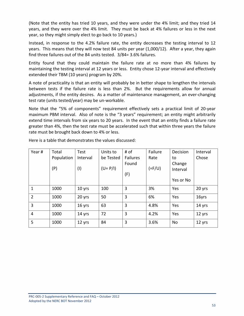
PRC‐005‐2 Supplementary Reference and FAQ – October 2012 Adopted by the NERC BOT November 2012 53
(Note that the entity has tried 10 years, and they were under the 4% limit; and they tried 14 years, and they were over the 4% limit. They must be back at 4% failures or less in the next year, so they might simply elect to go back to 10 years.)
Instead, in response to the 4.2% failure rate, the entity decreases the testing interval to 12 years. This means that they will now test 84 units per year (1,000/12). After a year, they again find three failures out of the 84 units tested. 3/84= 3.6% failures.
Entity found that they could maintain the failure rate at no more than 4% failures by maintaining the testing interval at 12 years or less. Entity chose 12‐year interval and effectively extended their TBM (10 years) program by 20%.
A note of practicality is that an entity will probably be in better shape to lengthen the intervals between tests if the failure rate is less than 2%. But the requirements allow for annual adjustments, if the entity desires. As a matter of maintenance management, an ever‐changing test rate (units tested/year) may be un‐workable.
Note that the “5% of components” requirement effectively sets a practical limit of 20‐year maximum PBM interval. Also of note is the “3 years” requirement; an entity might arbitrarily extend time intervals from six years to 20 years. In the event that an entity finds a failure rate greater than 4%, then the test rate must be accelerated such that within three years the failure rate must be brought back down to 4% or less.
Here is a table that demonstrates the values discussed:
Year # Total Population
(P)
Test Interval
(I)
Units to be Tested
(U= P/I)
# of Failures Found
(F)
Failure Rate
(=F/U)
Decision to Change Interval
Yes or No
Interval Chose
1 1000 10 yrs 100 3 3% Yes 20 yrs
2 1000 20 yrs 50 3 6% Yes 16yrs
3 1000 16 yrs 63 3 4.8% Yes 14 yrs
4 1000 14 yrs 72 3 4.2% Yes 12 yrs
5 1000 12 yrs 84 3 3.6% No 12 yrs

PRC‐005‐2 Supplementary Reference and FAQ – October 2012 Adopted by the NERC BOT November 2012 54
10. Overlapping the Verification of Sections of the Protection System
Tables 1‐1 through 1‐5 require that every Protection System component be periodically verified. One approach, but not the only method, is to test the entire protection scheme as a unit, from the secondary windings of voltage and current sources to breaker tripping. For practical ongoing verification, sections of the Protection System may be tested or monitored individually. The boundaries of the verified sections must overlap to ensure that there are no gaps in the verification. See Appendix A of this Supplementary Reference for additional discussion on this topic.
All of the methodologies expressed within this report may be combined by an entity, as appropriate, to establish and operate a maintenance program. For example, a Protection System may be divided into multiple overlapping sections with a different maintenance methodology for each section:
Time‐based maintenance with appropriate maximum verification intervals for categories of equipment, as given in the Tables 1‐1 through 1‐5;
Monitoring as described in Tables 1‐1 through 1‐5;
A Performance‐Based Maintenance program as described in Section 9 above, or Attachment A of the standard;
Opportunistic verification using analysis of Fault records, as described in Section 11
10.1 Frequently Asked Questions: My system has alarms that are gathered once daily through an auto-polling system; this is not really a conventional SCADA system but does it meet the Table 1 requirements for inclusion as a monitored system?
Yes, provided the auto‐polling that gathers the alarms reports those alarms to a location where the action can be initiated to correct the Unresolved Maintenance Issue. This location does not have to be the location of the engineer or the technician that will eventually repair the problem, but rather a location where the action can be initiated.

PRC‐005‐2 Supplementary Reference and FAQ – October 2012 Adopted by the NERC BOT November 2012 55
11. Monitoring by Analysis of Fault Records
Many users of microprocessor relays retrieve Fault event records and oscillographic records by data communications after a Fault. They analyze the data closely if there has been an apparent Misoperation, as NERC standards require. Some advanced users have commissioned automatic Fault record processing systems that gather and archive the data. They search for evidence of component failures or setting problems hidden behind an operation whose overall outcome seems to be correct. The relay data may be augmented with independently captured Digital Fault Recorder (DFR) data retrieved for the same event.
Fault data analysis comprises a legitimate CBM program that is capable of reducing the need for a manual time‐interval based check on Protection Systems whose operations are analyzed. Even electromechanical Protection Systems instrumented with DFR channels may achieve some CBM benefit. The completeness of the verification then depends on the number and variety of Faults in the vicinity of the relay that produce relay response records and the specific data captured.
A typical Fault record will verify particular parts of certain Protection Systems in the vicinity of the Fault. For a given Protection System installation, it may or may not be possible to gather within a reasonable amount of time an ensemble of internal and external Fault records that completely verify the Protection System.
For example, Fault records may verify that the particular relays that tripped are able to trip via the control circuit path that was specifically used to clear that Fault. A relay or DFR record may indicate correct operation of the protection communications channel. Furthermore, other nearby Protection Systems may verify that they restrain from tripping for a Fault just outside their respective zones of protection. The ensemble of internal Fault and nearby external Fault event data can verify major portions of the Protection System, and reset the time clock for the Table 1 testing intervals for the verified components only.
What can be shown from the records of one operation is very specific and limited. In a panel with multiple relays, only the specific relay(s) whose operation can be observed without ambiguity should be used. Be careful about using Fault response data to verify that settings or calibration are correct. Unless records have been captured for multiple Faults close to either side of a setting boundary, setting or calibration could still be incorrect.
PMU data, much like DME data, can be utilized to prove various components of the Protection System. Obviously, care must be taken to attribute proof only to the parts of a Protection System that can actually be proven using the PMU or DME data.
If Fault record data is used to show that portions or all of a Protection System have been verified to meet Table 1 requirements, the owner must retain the Fault records used, and the maintenance‐related conclusions drawn from this data and used to defer Table 1 tests, for at least the retention time interval given in Section 8.2.

PRC‐005‐2 Supplementary Reference and FAQ – October 2012 Adopted by the NERC BOT November 2012 56
11.1 Frequently Asked Questions:
I use my protective relays for Fault and Disturbance recording, collecting oscillographic records and event records via communications for Fault analysis to meet NERC and DME requirements. What are the maintenance requirements for the relays?
For relays used only as Disturbance Monitoring Equipment, NERC Standard PRC‐018‐1 R3 & R6 states the maintenance requirements and is being addressed by a standards activity that is revising PRC‐002‐1 and PRC‐018‐1. For protective relays “that are designed to provide protection for the BES,” this standard applies, even if they also perform DME functions.

PRC‐005‐2 Supplementary Reference and FAQ – October 2012 Adopted by the NERC BOT November 2012 57
12. Importance of Relay Settings in Maintenance Programs
In manual testing programs, many utilities depend on pickup value or zone boundary tests to show that the relays have correct settings and calibration. Microprocessor relays, by contrast, provide the means for continuously monitoring measurement accuracy. Furthermore, the relay digitizes inputs from one set of signals to perform all measurement functions in a single self‐monitoring microprocessor system. These relays do not require testing or calibration of each setting.
However, incorrect settings may be a bigger risk with microprocessor relays than with older relays. Some microprocessor relays have hundreds or thousands of settings, many of which are critical to Protection System performance.
Monitoring does not check measuring element settings. Analysis of Fault records may or may not reveal setting problems. To minimize risk of setting errors after commissioning, the user should enforce strict settings data base management, with reconfirmation (manual or automatic) that the installed settings are correct whenever maintenance activity might have changed them; for background and guidance, see [5] in References.
Table 1 requires that settings must be verified to be as specified. The reason for this requirement is simple: With legacy relays (non‐microprocessor protective relays), it is necessary to know the value of the intended setting in order to test, adjust and calibrate the relay. Proving that the relay works per specified setting was the de facto procedure. However, with the advanced microprocessor relays, it is possible to change relay settings for the purpose of verifying specific functions and then neglect to return the settings to the specified values. While there is no specific requirement to maintain a settings management process, there remains a need to verify that the settings left in the relay are the intended, specified settings. This need may manifest itself after any of the following:
One or more settings are changed for any reason.
A relay fails and is repaired or replaced with another unit.
A relay is upgraded with a new firmware version.
12.1 Frequently Asked Questions:
How do I approach testing when I have to upgrade firmware of a microprocessor relay?
The entity should ensure that the relay continues to function properly after implementation of firmware changes. Some entities may have a R&D department that might routinely run acceptance tests on devices with firmware upgrades before allowing the upgrade to be installed. Other entities may rely upon the vigorous testing of the firmware OEM. An entity has the latitude to install devices and/or programming that they believe will perform to their satisfaction. If an entity should choose to perform the maintenance activities specified in the Tables following a firmware upgrade, then they may, if they choose, reset the time clock on that set of maintenance activities so that they would not have to repeat the maintenance on its
PRC‐005‐2 Supplementary Reference and FAQ – October 2012 Adopted by the NERC BOT November 2012 58
regularly scheduled cycle. (However, for simplicity in maintenance schedules, some entities may choose to not reset this time clock; it is merely a suggested option.)
If I upgrade my old relays, then do I have to maintain my previous equipment maintenance documentation?
If an equipment item is repaired or replaced, then the entity can restart the maintenance‐activity‐time‐interval‐clock, if desired; however, the replacement of equipment does not remove any documentation requirements. The requirements in the standard are intended to ensure that an entity has a maintenance plan, and that the entity adheres to minimum activities and maximum time intervals. The documentation requirements are intended to help an entity demonstrate compliance. For example, saving the dates and records of the last two maintenance activities is intended to demonstrate compliance with the interval. Therefore, if you upgrade or replace equipment, then you still must maintain the documentation for the previous equipment, thus demonstrating compliance with the time interval requirement prior to the replacement action.
We have a number of installations where we have changed our Protection System components. Some of the changes were upgrades, but others were simply system rating changes that merely required taking relays “out-of-service”. What are our responsibilities when it comes to “out-of-service” devices?
Assuming that your system up‐rates, upgrades and overall changes meet any and all other requirements and standards, then the requirements of PRC‐005‐2 are simple – if the Protection System component performs a Protection System function, then it must be maintained. If the component no longer performs Protection System functions, then it does not require maintenance activities under the Tables of PRC‐005‐2. While many entities might physically remove a component that is no longer needed, there is no requirement in PRC‐005‐2 to remove such component(s). Obviously, prudence would dictate that an “out‐of‐service” device is truly made inactive. There are no record requirements listed in PRC‐005‐2 for Protection System components not used.
While performing relay testing of a protective device on our Bulk Electric System, it was discovered that the protective device being tested was either broken or out of calibration. Does this satisfy the relay testing requirement, even though the protective device tested bad, and may be unable to be placed back into service?
Yes, PRC‐005‐2 requires entities to perform relay testing on protective devices on a given maintenance cycle interval. By performing this testing, the entity has satisfied PRC‐005‐2 requirement, although the protective device may be unable to be returned to service under normal calibration adjustments. R5 states:
“R5. Each Transmission Owner, Generator Owner, and Distribution Provider shall demonstrate efforts to correct any identified Unresolved Maintenance Issues.”
Also, when a failure occurs in a Protection System, power system security may be comprised, and notification of the failure must be conducted in accordance with relevant NERC standards.
If I show the protective device out of service while it is being repaired, then can I add it back as a new protective device when it returns? If not, my relay testing history would show that I was out of compliance for the last maintenance cycle.
PRC‐005‐2 Supplementary Reference and FAQ – October 2012 Adopted by the NERC BOT November 2012 59
The maintenance and testing requirements (R5) state “…shall demonstrate efforts to correct any identified Unresolved Maintenance Issues...” The type of corrective activity is not stated; however, it could include repairs or replacements.
Your documentation requirements will increase, of course, to demonstrate that your device tested bad and had corrective actions initiated. Your regional entity might ask about the status of your corrective actions.

PRC‐005‐2 Supplementary Reference and FAQ – October 2012 Adopted by the NERC BOT November 2012 60
13. Self-Monitoring Capabilities and Limitations
Microprocessor relay proponents have cited the self‐monitoring capabilities of these products for nearly 20 years. Theoretically, any element that is monitored does not need a periodic manual test. A problem today is that the community of manufacturers and users has not created clear documentation of exactly what is and is not monitored. Some unmonitored but critical elements are buried in installed systems that are described as self‐monitoring.
To utilize the extended time intervals allowed by monitoring, the user must document that the monitoring attributes of the device match the minimum requirements listed in the Table 1.
Until users are able to document how all parts of a system which are required for the protective functions are monitored or verified (with help from manufacturers), they must continue with the unmonitored intervals established in Table 1 and Table 3.
Going forward, manufacturers and users can develop mappings of the monitoring within relays, and monitoring coverage by the relay of user circuits connected to the relay terminals.
To enable the use of the most extensive monitoring (and never again have a hands‐on maintenance requirement), the manufacturers of the microprocessor‐based self‐monitoring components in the Protection System should publish for the user a document or map that shows:
How all internal elements of the product are monitored for any failure that could impact Protection System performance.
Which connected circuits are monitored by checks implemented within the product; how to connect and set the product to assure monitoring of these connected circuits; and what circuits or potential problems are not monitored.
This manufacturer’s information can be used by the registered entity to document compliance of the monitoring attributes requirements by:
Presenting or referencing the product manufacturer’s documents.
Explaining in a system design document the mapping of how every component and circuit that is critical to protection is monitored by the microprocessor product(s) or by other design features.
Extending the monitoring to include the alarm transmission Facilities through which failures are reported within a given time frame to allocate where action can be taken to initiate resolution of the alarm attributed to an Unresolved Maintenance Issue, so that failures of monitoring or alarming systems also lead to alarms and action.
Documenting the plans for verification of any unmonitored components according to the requirements of Table 1 and Table 3.

PRC‐005‐2 Supplementary Reference and FAQ – October 2012 Adopted by the NERC BOT November 2012 61
13.1 Frequently Asked Questions:
I can’t figure out how to demonstrate compliance with the requirements for the highest level of monitoring of Protection Systems. Why does this Maintenance Standard describe a maintenance program approach I cannot achieve?
Demonstrating compliance with the requirements for the highest level of monitoring any particular component of Protection Systems is likely to be very involved, and may include detailed manufacturer documentation of complete internal monitoring within a device, comprehensive design drawing reviews, and other detailed documentation. This standard does not presume to specify what documentation must be developed; only that it must be documented.
There may actually be some equipment available that is capable of meeting these highest levels of monitoring criteria, in which case it may be maintained according to the highest level of monitoring shown on the Tables. However, even if there is no equipment available today that can meet this level of monitoring, the standard establishes the necessary requirements for when such equipment becomes available.
By creating a roadmap for development, this provision makes the standard technology‐neutral. The Standard Drafting Team wants to avoid the need to revise the standard in a few years to accommodate technology advances that may be coming to the industry.

PRC‐005‐2 Supplementary Reference and FAQ – October 2012 Adopted by the NERC BOT November 2012 62
14. Notification of Protection System Failures When a failure occurs in a Protection System, power system security may be compromised, and notification of the failure must be conducted in accordance with relevant NERC standard(s). Knowledge of the failure may impact the system operator’s decisions on acceptable Loading conditions.
This formal reporting of the failure and repair status to the system operator by the Protection System owner also encourages the system owner to execute repairs as rapidly as possible. In some cases, a microprocessor relay or carrier set can be replaced in hours; wiring termination failures may be repaired in a similar time frame. On the other hand, a component in an electromechanical or early‐generation electronic relay may be difficult to find and may hold up repair for weeks. In some situations, the owner may have to resort to a temporary protection panel, or complete panel replacement.

PRC‐005‐2 Supplementary Reference and FAQ – October 2012 Adopted by the NERC BOT November 2012 63
15. Maintenance Activities Some specific maintenance activities are a requirement to ensure reliability. An example would be that a BES entity could be prudent in its protective relay maintenance, but if its battery maintenance program is lacking, then reliability could still suffer. The NERC glossary outlines a Protection System as containing specific components. PRC‐005‐2 requires specific maintenance activities be accomplished within a specific time interval. As noted previously, higher technology equipment can contain integral monitoring capability that actually performs maintenance verification activities routinely and often; therefore, manual intervention to perform certain activities on these type components may not be needed.
15.1 Protective Relays (Table 1-1) These relays are defined as the devices that receive the input signal from the current and voltage sensing devices and are used to isolate a Faulted Element of the BES. Devices that sense thermal, vibration, seismic, pressure, gas, or any other non‐electrical inputs are excluded.
Non‐microprocessor based equipment is treated differently than microprocessor‐based equipment in the following ways; the relays should meet the asset owners’ tolerances:
Non‐microprocessor devices must be tested with voltage and/or current applied to the device.
Microprocessor devices may be tested through the integral testing of the device.
o There is no specific protective relay commissioning test or relay routine test mandated.
o There is no specific documentation mandated.
15.1.1 Frequently Asked Questions:
What calibration tolerance should be applied on electromechanical relays?
Each entity establishes their own acceptable tolerances when applying protective relaying on their system. For some Protection System components, adjustment is required to bring measurement accuracy within the parameters established by the asset owner based on the specific application of the component. A calibration failure is the result if testing finds the specified parameters to be out of tolerance.
15.2 Voltage & Current Sensing Devices (Table 1-3) These are the current and voltage sensing devices, usually known as instrument transformers. There is presently a technology available (fiber‐optic Hall‐effect) that does not utilize conventional transformer technology; these devices and other technologies that produce quantities that represent the primary values of voltage and current are considered to be a type of voltage and current sensing devices included in this standard.
The intent of the maintenance activity is to verify the input to the protective relay from the device that produces the current or voltage signal sample.
There is no specific test mandated for these components. The important thing about these signals is to know that the expected output from these components actually reaches the

PRC‐005‐2 Supplementary Reference and FAQ – October 2012 Adopted by the NERC BOT November 2012 64
protective relay. Therefore, the proof of the proper operation of these components also demonstrates the integrity of the wiring (or other medium used to convey the signal) from the current and voltage sensing device, all the way to the protective relay. The following observations apply:
There is no specific ratio test, routine test or commissioning test mandated.
There is no specific documentation mandated.
It is required that the signal be present at the relay.
This expectation can be arrived at from any of a number of means; including, but not limited to, the following: By calculation, by comparison to other circuits, by commissioning tests, by thorough inspection, or by any means needed to verify the circuit meets the asset owner’s Protection System maintenance program.
An example of testing might be a saturation test of a CT with the test values applied at the relay panel; this, therefore, tests the CT, as well as the wiring from the relay all the back to the CT.
Another possible test is to measure the signal from the voltage and/or current sensing devices, during Load conditions, at the input to the relay.
Another example of testing the various voltage and/or current sensing devices is to query the microprocessor relay for the Real‐time Loading; this can then be compared to other devices to verify the quantities applied to this relay. Since the input devices have supplied the proper values to the protective relay, then the verification activity has been satisfied. Thus, event reports (and oscillographs) can be used to verify that the voltage and current sensing devices are performing satisfactorily.
Still another method is to measure total watts and vars around the entire bus; this should add up to zero watts and zero vars, thus proving the voltage and/or current sensing devices system throughout the bus.
Another method for proving the voltage and/or current‐sensing devices is to complete commissioning tests on all of the transformers, cabling, fuses and wiring.
Any other method that verifies the input to the protective relay from the device that produces the current or voltage signal sample.

PRC‐005‐2 Supplementary Reference and FAQ – October 2012 Adopted by the NERC BOT November 2012 65
15.2.1 Frequently Asked Questions:
What is meant by “…verify the current and voltage circuit inputs from the voltage and current sensing devices to the protective relays …” Do we need to perform ratio, polarity and saturation tests every few years?
No. You must verify that the protective relay is receiving the expected values from the voltage and current‐sensing devices (typically voltage and current transformers). This can be as difficult as is proposed by the question (with additional testing on the cabling and substation wiring to ensure that the values arrive at the relays); or simplicity can be achieved by other verification methods. While some examples follow, these are not intended to represent an all‐inclusive list; technology advances and ingenuity should not be excluded from making comparisons and verifications:
Compare the secondary values, at the relay, to a metering circuit, fed by different current transformers, monitoring the same line as the questioned relay circuit.
Compare the individual phase secondary values at the relay panel (with additional testing on the panel wiring to ensure that the values arrive at those relays) with the other phases, and verify that residual currents are within expected bounds.
Observe all three phase currents and the residual current at the relay panel with an oscilloscope, observing comparable magnitudes and proper phase relationship, with additional testing on the panel wiring to ensure that the values arrive at the relays.
Compare the values, as determined by the questioned relay (such as, but not limited to, a query to the microprocessor relay) to another protective relay monitoring the same line, with currents supplied by different CTs.
Compare the secondary values, at the relay with values measured by test instruments (such as, but not limited to multi‐meters, voltmeter, clamp‐on ammeters, etc.) and verified by calculations and known ratios to be the values expected. For example, a single PT on a 100KV bus will have a specific secondary value that, when multiplied by the PT ratio, arrives at the expected bus value of 100KV.
Query SCADA for the power flows at the far end of the line protected by the questioned relay, compare those SCADA values to the values as determined by the questioned relay.
Totalize the Watts and VARs on the bus and compare the totals to the values as seen by the questioned relay.
The point of the verification procedure is to ensure that all of the individual components are functioning properly; and that an ongoing proactive procedure is in place to re‐check the various components of the protective relay measuring Systems.
Is wiring insulation or hi-pot testing required by this Maintenance Standard?
No, wiring insulation and equipment hi‐pot testing are not specifically required by the Maintenance Standard. However, if the method of verifying CT and PT inputs to the relay involves some other method than actual observation of current and voltage transformer secondary inputs to the relay, it might be necessary to perform some sort of cable integrity test to verify that the instrument transformer secondary signals are actually making it to the relay
PRC‐005‐2 Supplementary Reference and FAQ – October 2012 Adopted by the NERC BOT November 2012 66
and not being shunted off to ground. For instance, you could use CT excitation tests and PT turns ratio tests and compare to baseline values to verify that the instrument transformer outputs are acceptable. However, to conclude that these acceptable transformer instrument output signals are actually making it to the relay inputs, it also would be necessary to verify the insulation of the wiring between the instrument transformer and the relay.
My plant generator and transformer relays are electromechanical and do not have metering functions, as do microprocessor- based relays. In order for me to compare the instrument transformer inputs to these relays to the secondary values of other metered instrument transformers monitoring the same primary voltage and current signals, it would be necessary to temporarily connect test equipment, like voltmeters and clamp on ammeters, to measure the input signals to the relays. This practice seems very risky, and a plant trip could result if the technician were to make an error while measuring these current and voltage signals. How can I avoid this risk? Also, what if no other instrument transformers are available which monitor the same primary voltage or current signal?
Comparing the input signals to the relays to the outputs of other independent instrument transformers monitoring the same primary current or voltage is just one method of verifying the instrument transformer inputs to the relays, but is not required by the standard. Plants can choose how to best manage their risk. If online testing is deemed too risky, offline tests, such as, but not limited to, CT excitation test and PT turns ratio tests can be compared to baseline data and be used in conjunction with CT and PT secondary wiring insulation verification tests to adequately “verify the current and voltage circuit inputs from the voltage and current sensing devices to the protective relays …” while eliminating the risk of tripping an in service generator or transformer. Similarly, this same offline test methodology can be used to verify the relay input voltage and current signals to relays when there are no other instrument transformers monitoring available for purposes of signal comparison.
15.3 Control circuitry associated with protective functions (Table 1-5) This component of Protection Systems includes the trip coil(s) of the circuit breaker, circuit switcher or any other interrupting device. It includes the wiring from the batteries to the relays. It includes the wiring (or other signal conveyance) from every trip output to every trip coil. It includes any device needed for the correct processing of the needed trip signal to the trip coil of the interrupting device; this requirement is meant to capture inputs and outputs to and from a protective relay that are necessary for the correct operation of the protective functions. In short, every trip path must be verified; the method of verification is optional to the asset owner. An example of testing methods to accomplish this might be to verify, with a volt‐meter, the existence of the proper voltage at the open contacts, the open circuited input circuit and at the trip coil(s). As every parallel trip path has similar failure modes, each trip path from relay to trip coil must be verified. Each trip coil must be tested to trip the circuit breaker (or other interrupting device) at least once. There is a requirement to operate the circuit breaker (or other interrupting device) at least once every six years as part of the complete functional test. If a suitable monitoring system is installed that verifies every parallel trip path, then the manual‐intervention testing of those parallel trip paths can be eliminated; however, the actual operation of the circuit breaker must still occur at least once every six years. This six‐year tripping requirement can be completed as easily as tracking the Real‐time Fault‐clearing
PRC‐005‐2 Supplementary Reference and FAQ – October 2012 Adopted by the NERC BOT November 2012 67
operations on the circuit breaker, or tracking the trip coil(s) operation(s) during circuit breaker routine maintenance actions.
The circuit‐interrupting device should not be confused with a motor‐operated disconnect. The intent of this standard is to require maintenance intervals and activities on Protection Systems equipment, and not just all system isolating equipment.
It is necessary, however, to classify a device that actuates a high‐speed auto‐closing ground switch as an interrupting device, if this ground switch is utilized in a Protection System and forces a ground Fault to occur that then results in an expected Protection System operation to clear the forced ground Fault. The SDT believes that this is essentially a transferred‐tripping device without the use of communications equipment. If this high‐speed ground switch is “…designed to provide protection for the BES…” then this device needs to be treated as any other Protection System component. The control circuitry would have to be tested within 12 years, and any electromechanically operated device will have to be tested every six years. If the spring‐operated ground switch can be disconnected from the solenoid triggering unit, then the solenoid triggering unit can easily be tested without the actual closing of the ground blade.
The dc control circuitry also includes each auxiliary tripping relay (94) and each lock‐out relay (86) that may exist in any particular trip scheme. If the lock‐out relays (86) are electromechanical type components, then they must be trip tested. The PSMT SDT considers these components to share some similarities in failure modes as electromechanical protective relays; as such, there is a six‐year maximum interval between mandated maintenance tasks unless PBM is applied.
Contacts of the 86 and/or 94 that pass the trip current on to the circuit interrupting device trip coils will have to be checked as part of the 12 year requirement. Contacts of the 86 and/or 94 lock relay that operate non‐BES interrupting devices are not required. Normally‐open contacts that are not used to pass a trip signal and normally‐closed contacts do not have to be verified. Verification of the tripping paths is the requirement.
While relays that do not respond to electrical quantities are presently excluded from this standard, their control circuits are included if the relay is installed to detect Faults on BES Elements. Thus, the control circuit of a BES transformer sudden pressure relay should be verified every 12 years, assuming its integrity is not monitored. While a sudden pressure relay control circuit is included within the scope of PRC‐005‐2, other alarming relay control circuits, (i.e., SF‐6 low gas) are not included, even though they may trip the breaker being monitored.
New technology is also accommodated here; there are some tripping systems that have replaced the traditional hard‐wired trip circuitry with other methods of trip‐signal conveyance such as fiber‐optics. It is the intent of the PSMT SDT to include this, and any other, technology that is used to convey a trip signal from a protective relay to a circuit breaker (or other interrupting device) within this category of equipment. The requirement for these systems is verification of the tripping path.
Monitoring of the control circuit integrity allows for no maintenance activity on the control circuit (excluding the requirement to operate trip coils and electromechanical lockout and/or tripping auxiliary relays). Monitoring of integrity means to monitor for continuity and/or presence of voltage on each trip path. For Ethernet or fiber‐optic control systems, monitoring of integrity means to monitor communication ability between the relay and the circuit breaker.

PRC‐005‐2 Supplementary Reference and FAQ – October 2012 Adopted by the NERC BOT November 2012 68
The trip path from a sudden pressure device is a part of the Protection System control circuitry. The sensing element is omitted from PRC‐005‐2 testing requirements because the SDT is unaware of industry‐recognized testing protocol for the sensing elements. The SDT believes that Protection Systems that trip (or can trip) the BES should be included. This position is consistent with the currently‐approved PRC‐005‐1, consistent with the SAR for Project 2007‐17, and understands this to be consistent with the position of FERC staff.
15.3.1 Frequently Asked Questions:
Is it permissible to verify circuit breaker tripping at a different time (and interval) than when we verify the protective relays and the instrument transformers? Yes, provided the entire Protective System is tested within the individual component’s maximum allowable testing intervals.
The Protection System Maintenance Standard describes requirements for verifying the tripping of circuit breakers. What is this telling me about maintenance of circuit breakers? Requirements in PRC‐005‐2 are intended to verify the integrity of tripping circuits, including the breaker trip coil, as well as the presence of auxiliary supply (usually a battery) for energizing the trip coil if a protection function operates. Beyond this, PRC‐005‐2 sets no requirements for verifying circuit breaker performance, or for maintenance of the circuit breaker.
How do I test each dc Control Circuit trip path, as established in Table 1-5 “Protection System Control Circuitry (Trip coils and auxiliary relays)”? Table 1‐5 specifies that each breaker trip coil and lockout relays that carry trip current to a trip coil must be operated within the specified time period. The required operations may be via targeted maintenance activities, or by documented operation of these devices for other purposes such as Fault clearing.
Are high-speed ground switch trip coils included in the dc control circuitry? Yes. PRC‐005‐2 includes high‐speed grounding switch trip coils within the dc control circuitry to the degree that the initiating Protection Systems are characterized as “transmission Protection Systems.”
Does the control circuitry and trip coil of a non-BES breaker, tripped via a BES protection component, have to be tested per Table 1.5? (Refer to Table 3 for examples 1 and 2)Example 1: A non‐BES circuit breaker that is tripped via a Protection System to which PRC‐005‐2 applies might be (but is not limited to) a 12.5KV circuit breaker feeding (non‐black‐start) radial Loads but has a trip that originates from an under‐frequency (81) relay.
The relay must be verified.
The voltage signal to the relay must be verified.
All of the relevant dc supply tests still apply.
.
The unmonitored trip circuit between the relay and any lock‐out or auxiliary relay must be verified every 12 years.

PRC‐005‐2 Supplementary Reference and FAQ – October 2012 Adopted by the NERC BOT November 2012 69
The unmonitored trip circuit between the lock‐out (or auxiliary relay) and the non‐BES breaker does not have to be proven with an electrical trip.
In the case where there is no lock‐out or auxiliary tripping relay used, the trip circuit to the non‐BES breaker does not have to be proven with an electrical trip.
The trip coil of the non‐BES circuit breaker does not have to be individually proven with an electrical trip.
Example 2: A Transmission Owner may have a non‐BES breaker that is tripped via a Protection System to which PRC‐005‐2 applies, which may be (but is not limted to) a 13.8 KV circuit breaker feeding (non‐black‐start) radial Loads but has a trip that originates from a BES 115KV line relay.
The relay must be verified
The voltage signal to the relay must be verified
All of the relevant dc supply tests still apply
The unmonitored trip circuit between the relay and any lock‐out (86) or auxiliary (94) relay must be verified every 12 years
The unmonitored trip circuit between the lock‐out (86) (or auxiliary (94)) relay and the non‐BES breaker does not have to be proven with an electrical trip
In the case where there is no lockout (86) or auxiliary (94) tripping relay used, the trip circuit to the non‐BES breaker does not have to be proven with an electrical trip.
The trip coil of the non‐BES circuit breaker does not have to be individually proven with an electrical trip
Example 3: A Generator Owner may have an non‐BES circuit breaker that is tripped via a Protection System to which PRC‐005‐2 applies, such as the generator field breaker and low‐side breakers on station service/excitation transformers connected to the generator bus.
Trip testing of the generator field breaker and low side station service/excitation transformer breaker(s) via lockout or auxiliairy tripping relays are not required since these breakers may be associated with radially fed loads and are not considered to be BES breakers. An example of an otherwise non‐BES circuit breaker that is tripped via a BES protection component might be (but is not limited to) a 6.9kV station service transformer source circuit breaker but has a trip that originates from a generator differential (87) relay.
The differential relay must be verified.
The current signals to the relay must be verified.
All of the relevant dc supply tests still apply.
The unmonitored trip circuit between the relay and any lock‐out or auxiliary relay must be verified every 12 years.
The unmonitored trip circuit between the lock‐out (or auxiliary relay) and the non‐BES breaker does not have to be proven with an electrical trip.
In the case where there is no lock‐out or auxiliary tripping relay used, the trip circuit to the non‐BES breaker does not have to be proven with an electrical trip.

PRC‐005‐2 Supplementary Reference and FAQ – October 2012 Adopted by the NERC BOT November 2012 70
The trip coil of the non‐BES circuit breaker does not have to be individually proven with an electrical trip.
However, it is very prudent to verify the tripping of such breakers for the integrity of the overall generation plant.
Do I have to verify operation of breaker “a” contacts or any other normally closed auxiliary contacts in the trip path of each breaker as part of my control circuit test? Operation of normally‐closed contacts does not have to be verified. Verification of the tripping paths is the requirement. The continuity of the normally closed contacts will be verified when the tripping path is verified.
15.4 Batteries and DC Supplies (Table 1-4) The NERC definition of a Protection System is:
Protective relays which respond to electrical quantities,
Communications Systems necessary for correct operation of protective functions,
Voltage and current sensing devices providing inputs to protective relays,
Station dc supply associated with protective functions (including station batteries, battery chargers, and non‐battery‐based dc supply), and
Control circuitry associated with protective functions through the trip coil(s) of the circuit breakers or other interrupting devices.
The station battery is not the only component that provides dc power to a Protection System. In the new definition for Protection System, “station batteries” are replaced with “station dc supply” to make the battery charger and dc producing stored energy devices (that are not a battery) part of the Protection System that must be maintained.
The PSMT SDT recognizes that there are several technological advances in equipment and testing procedures that allow the owner to choose how to verify that a battery string is free of open circuits. The term “continuity” was introduced into the standard to allow the owner to choose how to verify continuity of a battery set by various methods, and not to limit the owner to other conventional methods of showing continuity. Continuity, as used in Table 1‐4 of the standard, refers to verifying that there is a continuous current path from the positive terminal of the station battery set to the negative terminal. Without verifying continuity of a station battery, there is no way to determine that the station battery is available to supply dc power to the station. An open battery string will be an unavailable power source in the event of loss of the battery charger.
Batteries cannot be a unique population segment of a Performance‐Based Maintenance Program (PBM) because there are too many variables in the electrochemical process to completely isolate all of the performance‐changing criteria necessary for using PBM on battery Systems. However, nothing precludes the use of a PBM process for any other part of a dc supply besides the batteries themselves.
PRC‐005‐2 Supplementary Reference and FAQ – October 2012 Adopted by the NERC BOT November 2012 71
15.4.1 Frequently Asked Questions:
What constitutes the station dc supply, as mentioned in the definition of Protective System? The previous definition of Protection System includes batteries, but leaves out chargers. The latest definition includes chargers, as well as dc systems that do not utilize batteries. This revision of PRC‐005‐2 is intended to capture these devices that were not included under the previous definition. The station direct current (dc) supply normally consists of two components: the battery charger and the station battery itself. There are also emerging technologies that provide a source of dc supply that does not include either a battery or charger.
Battery Charger ‐ The battery charger is supplied by an available ac source. At a minimum, the battery charger must be sized to charge the battery (after discharge) and supply the constant dc load. In many cases, it may be sized also to provide sufficient dc current to handle the higher energy requirements of tripping breakers and switches when actuated by the protective relays in the Protection System.
Station Battery ‐ Station batteries provide the dc power required for tripping and for supplying normal dc power to the station in the event of loss of the battery charger. There are several technologies of battery that require unique forms of maintenance as established in Table 1‐4.
Emerging Technologies ‐ Station dc supplies are currently being developed that use other energy storage technologies besides the station battery to prevent loss of the station dc supply when ac power is lost. Maintenance of these station dc supplies will require different kinds of tests and inspections. Table 1‐4 presents maintenance activities and maximum allowable testing intervals for these new station dc supply technologies. However, because these technologies are relatively new, the maintenance activities for these station dc supplies may change over time.
What did the PSMT SDT mean by “continuity” of the dc supply? The PSMT SDT recognizes that there are several technological advances in equipment and testing procedures that allow the owner to choose how to verify that a battery string is free of open circuits. The term “continuity” was introduced into the standard to allow the owner to choose how to verify continuity (no open circuits) of a battery set by various methods, and not to limit the owner to other conventional methods of showing continuity – lack of an open circuit. Continuity, as used in Table 1‐4 of the standard, refers to verifying that there is a continuous current path from the positive terminal of the station battery set to the negative terminal (no open circuit). Without verifying continuity of a station battery, there is no way to determine that the station battery is available to supply dc power to the station. Whether it is caused from an open cell or a bad external connection, an open battery string will be an unavailable power source in the event of loss of the battery charger. The current path through a station battery from its positive to its negative connection to the dc control circuits is composed of two types of elements. These path elements are the electrochemical path through each of its cells and all of the internal and external metallic connections and terminations of the batteries in the battery set. If there is loss of continuity (an open circuit) in any part of the electrochemical or metallic path, the battery set will not be available for service. In the event of the loss of the ac source or battery charger, the battery

PRC‐005‐2 Supplementary Reference and FAQ – October 2012 Adopted by the NERC BOT November 2012 72
must be capable of supplying dc current, both for continuous dc loads and for tripping breakers and switches. Without continuity, the battery cannot perform this function. At generating stations and large transmission stations where battery chargers are capable of handling the maximum current required by the Protection System, there are still problems that could potentially occur when the continuity through the connected battery is interrupted.
Many battery chargers produce harmonics which can cause failure of dc power supplies in microprocessor‐based protective relays and other electronic devices connected to station dc supply. In these cases, the substation battery serves as a filter for these harmonics. With the loss of continuity in the battery, the filter provided by the battery is no longer present.
Loss of electrical continuity of the station battery will cause, in most battery chargers, regardless of the battery charger’s output current capability, a delayed response in full output current from the charger. Almost all chargers have an intentional one‐ to two‐second delay to switch from a low substation dc load current to the maximum output of the charger. This delay would cause the opening of circuit breakers to be delayed, which could violate system performance standards.
Monitoring of the station dc supply voltage will not indicate that there is a problem with the dc current path through the battery, unless the battery charger is taken out of service. At that time, a break in the continuity of the station battery current path will be revealed because there will be no voltage on the station dc circuitry. This particular test method, while proving battery continuity, may not be acceptable to all installations.
Although the standard prescribes what must be accomplished during the maintenance activity, it does not prescribe how the maintenance activity should be accomplished. There are several methods that can be used to verify the electrical continuity of the battery. These are not the only possible methods, simply a sampling of some methods:
One method is to measure that there is current flowing through the battery itself by a simple clamp on milliamp‐range ammeter. A battery is always either charging or discharging. Even when a battery is charged, there is still a measurable float charge current that can be detected to verify that there is continuity in the electrical path through the battery.
A simple test for continuity is to remove the battery charger from service and verify that the battery provides voltage and current to the dc system. However, the behavior of the various dc‐supplied equipment in the station should be considered before using this approach.
Manufacturers of microprocessor‐controlled battery chargers have developed methods for their equipment to periodically (or continuously) test for battery continuity. For example, one manufacturer periodically reduces the float voltage on the battery until current from the battery to the dc load can be measured to confirm continuity.
Applying test current (as in some ohmic testing devices, or devices for locating dc grounds) will provide a current that when measured elsewhere in the string, will prove that the circuit is continuous.

PRC‐005‐2 Supplementary Reference and FAQ – October 2012 Adopted by the NERC BOT November 2012 73
Internal ohmic measurements of the cells and units of lead‐acid batteries (VRLA & VLA) can detect lack of continuity within the cells of a battery string; and when used in conjunction with resistance measurements of the battery’s external connections, can prove continuity. Also some methods of taking internal ohmic measurements, by their very nature, can prove the continuity of a battery string without having to use the results of resistance measurements of the external connections.
Specific gravity tests could infer continuity because without continuity there could be no charging occurring; and if there is no charging, then specific gravity will go down below acceptable levels over time.
No matter how the electrical continuity of a battery set is verified, it is a necessary maintenance activity that must be performed at the intervals prescribed by Table 1‐4 to insure that the station dc supply has a path that can provide the required current to the Protection System at all times.
When should I check the station batteries to see if they have sufficient energy to perform as manufactured? The answer to this question depends on the type of battery (valve‐regulated lead‐acid, vented lead‐acid, or nickel‐cadmium) and the maintenance activity chosen.
For example, if you have a valve‐regulated lead‐acid (VRLA) station battery, and you have chosen to evaluate the measured cell/unit internal ohmic values to the battery cell’s baseline, you will have to perform verification at a maximum maintenance interval of no greater than every six months. While this interval might seem to be quite short, keep in mind that the six‐month interval is important for VRLA batteries; this interval provides an accumulation of data that better shows when a VRLA battery is incapable of performing as manufactured.
If, for a VRLA station battery, you choose to conduct a performance capacity test on the entire station battery as the maintenance activity, then you will have to perform verification at a maximum maintenance interval of no greater than every three calendar years.
How is a baseline established for cell/unit internal ohmic measurements? Establishment of cell/unit internal ohmic baseline measurements should be completed when lead‐acid batteries are newly installed. To ensure that the baseline ohmic cell/unit values are most indicative of the station battery’s ability to perform as manufactured, they should be made at some point in time after the installation to allow the cell chemistry to stabilize after the initial freshening charge. An accepted industry practice for establishing baseline values is after six‐months of installation, with the battery fully charged and in service. However, it is recommended that each owner, when establishing a baseline, should consult the battery manufacturer for specific instructions on establishing an ohmic baseline for their product, if available.
When internal ohmic measurements are taken, the same make/model test equipment should be used to establish the baseline and used for the future trending of the cells internal ohmic measurements because of variances in test equipment and the type of ohmic measurement used by different manufacturer’s equipment. Keep in mind that one manufacturer’s “Conductance” test equipment does not produce similar results as another manufacturer’s “Conductance” test equipment, even though both manufacturers have produced “Ohmic” test

PRC‐005‐2 Supplementary Reference and FAQ – October 2012 Adopted by the NERC BOT November 2012 74
equipment. Therefore, for meaningful results to an established baseline, the same make/modelof instrument should be used.
For all new installations of valve‐regulated lead‐acid (VRLA) batteries and vented lead‐acid (VLA) batteries, where trending of the cells internal ohmic measurements to a baseline are to be used to determine the ability of the station battery to perform as manufactured, the establishment of the baseline, as described above, should be followed at the time of installation to insure the most accurate trending of the cell/unit. However, often for older VRLA batteries, the owners of the station batteries have not established a baseline at installation. Also for owners of VLA batteries who want to establish a maintenance activity which requires trending of measured ohmic values to a baseline, there was typically no baseline established at installation of the station battery to trend to.
To resolve the problem of the unavailability of baseline internal ohmic measurements for the individual cell/unit of a station battery, many manufacturers of internal ohmic measurement devices have established libraries of baseline values for VRLA and VLA batteries using their testing device. Also, several of the battery manufacturers have libraries of baselines for their products that can be used to trend to. However, it is important that when using battery manufacturer‐supplied data that it is verified that the baseline readings to be used were taken with the same ohmic testing device that will be used for future measurements (for example “Conductance Readings” from one manufacturer’s test equipment do not correlate to “Impedance Readings” from a different manufacturer’s test equipment). Although many manufacturers may have provided baseline values, which will allow trending of the internal ohmic measurements over the remaining life of a station battery, these baselines are not the actual cell/unit measurements for the battery being trended. It is important to have a baseline tailored to the station battery to more accurately use the tool of ohmic measurement trending. That more customized baseline can only be created by following the establishment of a baseline for each cell/unit at the time of installation of the station battery.
Why determine the State of Charge? Even though there is no present requirement to check the state of charge of a battery, it can be a very useful tool in determining the overall condition of a battery system. The following discussions are offered as a general reference.
When a battery is fully charged, the battery is available to deliver its existing capacity. As a battery is discharged, its ability to deliver its maximum available capacity is diminished. It is necessary to determine if the state of charge has dropped to an unacceptable level.
What is State of Charge and how can it be determined in a station battery? The state of charge of a battery refers to the ratio of residual capacity at a given instant to the maximum capacity available from the battery. When a battery is fully charged, the battery is available to deliver its existing capacity. As a battery is discharged, its ability to deliver its maximum available capacity is diminished. Knowing the amount of energy left in a battery compared with the energy it had when it was fully charged gives the user an indication of how much longer a battery will continue to perform before it needs recharging.
For vented lead‐acid (VLA) batteries which use accessible liquid electrolyte, a hydrometer can be used to test the specific gravity of each cell as a measure of its state of charge. The hydrometer depends on measuring changes in the weight of the active chemicals. As the
PRC‐005‐2 Supplementary Reference and FAQ – October 2012 Adopted by the NERC BOT November 2012 75
battery discharges, the active electrolyte, sulfuric acid, is consumed and the concentration of the sulfuric acid in water is reduced. This, in turn, reduces the specific gravity of the solution in direct proportion to the state of charge. The actual specific gravity of the electrolyte can, therefore, be used as an indication of the state of charge of the battery. Hydrometer readings may not tell the whole story, as it takes a while for the acid to get mixed up in the cells of a VLA battery. If measured right after charging, you might see high specific gravity readings at the top of the cell, even though it is much less at the bottom. Conversely, if taken shortly after adding water to the cell, the specific gravity readings near the top of the cell will be lower than those at the bottom.
Nickel‐cadmium batteries, where the specific gravity of the electrolyte does not change during battery charge and discharge, and valve‐regulated lead‐acid (VRLA) batteries, where the electrolyte is not accessible, cannot have their state of charge determined by specific gravity readings. For these two types of batteries, and for VLA batteries also, where another method besides taking hydrometer readings is desired, the state of charge may be determined by taking voltage and current readings at the battery terminals. The methods employed to obtain accurate readings vary for the different battery types. Manufacturers’ information and IEEE guidelines can be consulted for specifics; (see IEEE 1106 Annex B for Nickel Cadmium batteries, IEEE 1188 Annex A for VRLA batteries and IEEE 450 for VLA batteries.
Why determine the Connection Resistance? High connection resistance can cause abnormal voltage drop or excessive heating during discharge of a station battery. During periods of a high rate of discharge of the station battery, a very high resistance can cause severe damage. The maintenance requirement to verify battery terminal connection resistance in Table 1‐4 is established to verify that the integrity of all battery electrical connections is acceptable. This verification includes cell‐to‐cell (intercell) and external circuit terminations. Your method of checking for acceptable values of intercell and terminal connection resistance could be by individual readings, or a combination of the two. There are test methods presently that can read post termination resistances and resistance values between external posts. There are also test methods presently available that take a combination reading of the post termination connection resistance plus the intercell resistance value plus the post termination connection resistance value. Either of the two methods, or any other method, that can show if the adequacy of connections at the battery posts is acceptable. Adequacy of the electrical terminations can be determined by comparing resistance measurements for all connections taken at the time of station battery’s installation to the same resistance measurements taken at the maintenance interval chosen, not to exceed the maximum maintenance interval of Table 1‐4. Trending of the interval measurements to the baseline measurements will identify any degradation in the battery connections. When the connection resistance values exceed the acceptance criteria for the connection, the connection is typically disassembled, cleaned, reassembled and measurements taken to verify that the measurements are adequate when compared to the baseline readings.
What conditions should be inspected for visible battery cells? The maintenance requirement to inspect the cell condition of all station battery cells where the cells are visible is a maintenance requirement of Table 1‐4. Station batteries are different from any other component in the Protection Station because they are a perishable product due to the electrochemical process which is used to produce dc electrical current and voltage. This

PRC‐005‐2 Supplementary Reference and FAQ – October 2012 Adopted by the NERC BOT November 2012 76
inspection is a detailed visual inspection of the cells for abnormalities that occur in the aging process of the cell. In VLA battery visual inspections, some of the things that the inspector is typically looking for on the plates are signs of sulfation of the plates, abnormal colors (which are an indicator of sulfation or possible copper contamination) and abnormal conditions such as cracked grids. The visual inspection could look for symptoms of hydration that would indicate that the battery has been left in a completely discharged state for a prolonged period. Besides looking at the plates for signs of aging, all internal connections, such as the bus bar connection to each plate, and the connections to all posts of the battery need to be visually inspected for abnormalities. In a complete visual inspection for the condition of the cell the cell plates, separators and sediment space of each cell must be looked at for signs of deterioration. An inspection of the station battery’s cell condition also includes looking at all terminal posts and cell‐to‐cell electric connections to ensure they are corrosion free. The case of the battery containing the cell, or cells, must be inspected for cracks and electrolyte leaks through cracks and the post seals.
This maintenance activity cannot be extended beyond the maximum maintenance interval of Table 1‐4 by a Performance‐Based Maintenance Program (PBM) because of the electrochemical aging process of the station battery, nor can there be any monitoring associated with it because there must be a visual inspection involved in the activity. A remote visual inspection could possibly be done, but its interval must be no greater than the maximum maintenance interval of Table 1‐4.
Why is it necessary to verify the battery string can perform as manufactured? I only care that the battery can trip the breaker, which means that the battery can perform as designed. I oversize my batteries so that even if the battery cannot perform as manufactured, it can still trip my breakers. The fundamental answer to this question revolves around the concept of battery performance “as designed” vs. battery performance “as manufactured.” The purpose of the various sections of Table 1‐4 of this standard is to establish requirements for the Protection System owner to maintain the batteries, to ensure they will operate the equipment when there is an incident that requires dc power, and ensure the batteries will continue to provide adequate service until at least the next maintenance interval. To meet these goals, the correct battery has to be properly selected to meet the design parameters, and the battery has to deliver the power it was manufactured to provide.
When testing batteries, it may be difficult to determine the original design (i.e., load profile) of the dc system. This standard is not intended as a design document, and requirements relating to design are, therefore, not included.
Where the dc load profile is known, the best way to determine if the system will operate as designed is to conduct a service test on the battery. However, a service test alone might not fully determine if the battery is healthy. A battery with 50% capacity may be able to pass a service test, but the battery would be in a serious state of deterioration and could fail at some point in the near future.
To ensure that the battery will meet the required load profile and continue to meet the load profile until the next maintenance interval, the installed battery must be sized correctly (i.e., a correct design), and it must be in a good state of health. Since the design of the dc system is not within the scope of the standard, the only consistent and reliable method to ensure that

PRC‐005‐2 Supplementary Reference and FAQ – October 2012 Adopted by the NERC BOT November 2012 77
the battery is in a good state of health is to confirm that it can perform as manufactured. If the battery can perform as manufactured and it has been designed properly, the system should operate properly until the next maintenance interval.
How do I verify the battery string can perform as manufactured? Optimally, actual battery performance should be verified against the manufacturer’s rating curves. The best practice for evaluating battery performance is via a performance test. However, due to both logistical and system reliability concerns, some Protection System owners prefer other methods to determine if a battery can perform as manufactured. There are several battery parameters that can be evaluated to determine if a battery can perform as manufactured. Ohmic measurements and float current are two examples of parameters that have been reported to assist in determining if a battery string can perform as manufactured.
The evaluation of battery parameters in determining battery health is a complex issue, and is not an exact science. This standard gives the user an opportunity to utilize other measured parameters to determine if the battery can perform as manufactured. It is the responsibility of the Protection System owner, however, to maintain a documented process that demonstrates the chosen parameter(s) and associated methodology used to determine if the battery string can perform as manufactured.
Whatever parameters are used to evaluate the battery (ohmic measurements, float current, float voltages, temperature, specific gravity, performance test, or combination thereof), the goal is to determine the value of the measurement (or the percentage change) at which the battery fails to perform as manufactured, or the point where the battery is deteriorating so rapidly that it will not perform as manufactured before the next maintenance interval.
This necessitates the need for establishing and documenting a baseline. A baseline may be required of every individual cell, a particular battery installation, or a specific make, model, or size of a cell. Given a consistent cell manufacturing process, it may be possible to establish a baseline number for the cell (make/model/type) and, therefore, a subsequent baseline for every installation would not be necessary. However, future installations of the same battery types should be spot‐checked to ensure that your baseline remains applicable.
Consistent testing methods by trained personnel are essential. Moreover, it is essential that these technicians utilize the same make/model of ohmic test equipment each time readings are taken in order to establish a meaningful and accurate trendline against the established baseline. The type of probe and its location (post, connector, etc) for the reading need to be the same for each subsequent test. The room temperature should be recorded with the readings for each test as well. Care should be taken to consider any factors that might lead a trending program to become invalid.
Float current along with other measureable parameters can be used in lieu of or in concert with ohmic measurement testing to measure the ability of a battery to perform as manufactured. The key to using any of these measurement parameters is to establish a baseline and the point where the reading indicates that the battery will not perform as manufactured.
The establishment of a baseline may be different for various types of cells and for different types of installations. In some cases, it may be possible to obtain a baseline number from the

PRC‐005‐2 Supplementary Reference and FAQ – October 2012 Adopted by the NERC BOT November 2012 78
battery manufacturer, although it is much more likely that the baseline will have to be established after the installation is complete. To some degree, the battery may still be “forming” after installation; consequently, determining a stable baseline may not be possible until several months after the battery has been in service.
The most important part of this process is to determine the point where the ohmic reading (or other measured parameter(s)) indicates that the battery cannot perform as manufactured. That point could be an absolute number, an absolute change, or a percentage change of an established baseline.
Since there are no universally‐accepted repositories of this information, the Protection System owner will have to determine the value/percentage where the battery cannot perform as manufactured (heretofore referred to as a failed cell). This is the most difficult and important part of the entire process.
To determine the point where the battery fails to perform as manufactured, it is helpful to have a history of a battery type, if the data includes the parameter(s) used to evaluate the battery's ability to perform as manufactured against the actual demonstrated performance/capacity of a battery/cell.
For example, when an ohmic reading has been recorded that the user suspects is indicating a failed cell, a performance test of that cell (or string) should be conducted in order to prove/quantify that the cell has failed. Through this process, the user needs to determine the ohmic value at which the performance of the cell has dropped below 80% of the manufactured, rated performance. It is likely that there may be a variation in ohmic readings that indicates a failed cell (possibly significant). It is prudent to use the most conservative values to determine the point at which the cell should be marked for replacement. Periodically, the user should demonstrate that an “adequate” ohmic reading equates to an adequate battery performance (>80% of capacity).
Similarly, acceptance criteria for "good" and "failed" cells should be established for other parameters such as float current, specific gravity, etc., if used to determine the ability of a battery to function as designed.
What happens if I change the make/model of ohmic test equipment after the battery has been installed for a period of time?
If a user decides to switch testers, either voluntarily or because the equipment is not supported/sold any longer, the user may have to establish a new base line and new parameters that indicate when the battery no longer performs as manufactured. The user always has a choice to perform a capacity test in lieu of establishing new parameters.
What are some of the differences between lead-acid and nickel-cadmium batteries? There is a marked difference in the aging process of lead acid and nickel‐cadmium station batteries. The difference in the aging process of these two types of batteries is chiefly due to the electrochemical process of the battery type. Aging and eventual failure of lead acid batteries is due to expansion and corrosion of the positive grid structure, loss of positive plate active material, and loss of capacity caused by physical changes in the active material of the positive plates. In contrast, the primary failure of nickel‐cadmium batteries is due to the

PRC‐005‐2 Supplementary Reference and FAQ – October 2012 Adopted by the NERC BOT November 2012 79
gradual linear aging of the active materials in the plates. The electrolyte of a nickel‐cadmium battery only facilitates the chemical reaction (it functions only to transfer ions between the positive and negative plates), but is not chemically altered during the process like the electrolyte of a lead acid battery. A lead acid battery experiences continued corrosion of the positive plate and grid structure throughout its operational life while a nickel‐cadmium battery does not.
Changes to the properties of a lead acid battery when periodically measured and trended to a baseline, can indicate aging of the grid structure, positive plate deterioration, or changes in the active materials in the plate.
Because of the clear differences in the aging process of lead acid and nickel‐cadmium batteries, there are no significantly measurable properties of the nickel‐cadmium battery that can be measured at a periodic interval and trended to determine aging. For this reason, Table 1‐4(c) (Protection System Station dc supply Using nickel‐cadmium [NiCad] Batteries) only specifies one minimum maintenance activity and associated maximum maintenance interval necessary to verify that the station battery can perform as manufactured by evaluating cell/unit measurements indicative of battery performance against the station battery baseline. This maintenance activity is to conduct a performance or modified performance capacity test of the entire battery bank.
Why in Table 1-4 of PRC-005-2 is there a maintenance activity to inspect the structural intergrity of the battery rack? The purpose of this inspection is to verify that the battery rack is correctly installed and has no deterioration that could weaken its structural integrity. Because the battery rack is specifically manufactured for the battery that is mounted on it, weakening of its structural members by rust or corrosion can physically jeopardize the battery.
What is required to comply with the “Unintentional dc Grounds” requirement? In most cases, the first ground that appears on a battery is not a problem. It is the unintentional ground that appears on the opposite pole that becomes problematic. Even then many systems are designed to operate favorably under some unintentional DC ground situations. It is up to the owner of the Protection System to determine if corrective actions are needed on detected unintentional DC grounds. The standard merely requires that a check be made for the existence of Unintentional DC Grounds. Obviously, a “check‐off” of some sort will have to be devised by the inspecting entity to document that a check is routinely done for Unintentional DC Grounds because of the possible consequences to the Protection System.
Where the standard refers to “all cells,” is it sufficient to have a documentation method that refers to “all cells,” or do we need to have separate documentation for every cell? For example, do I need 60 individual documented check-offs for good electrolyte level, or would a single check-off per bank be sufficient? A single check‐off per battery bank is sufficient for documentation, as long as the single check‐off attests to checking all cells/units.
Does this standard refer to Station batteries or all batteries; for example, Communications Site Batteries? This standard refers to Station Batteries. The drafting team does not believe that the scope of this standard refers to communications sites. The batteries covered under PRC‐005‐2 are the batteries that supply the trip current to the trip coils of the interrupting devices that are a part

PRC‐005‐2 Supplementary Reference and FAQ – October 2012 Adopted by the NERC BOT November 2012 80
of the Protection System. The SDT believes that a loss of power to the communications systems at a remote site would cause the communications systems associated with protective relays to alarm at the substation. At this point, the corrective actions can be initiated.
What are cell/unit internal ohmic measurements? With the introduction of Valve‐Regulated Lead‐Acid (VRLA) batteries to station dc supplies in the 1980’s several of the standard maintenance tools that are used on Vented Lead‐Acid (VLA) batteries were unable to be used on this new type of lead‐acid battery to determine its state of health. The only tools that were available to give indication of the health of these new VRLA batteries were voltage readings of the total battery voltage, the voltage of the individual cells and periodic discharge tests.
In the search for a tool for determining the health of a VRLA battery several manufacturers studied the electrical model of a lead acid battery’s current path through its cell. The overall battery current path consists of resistance and inductive and capacitive reactance. The inductive reactance in the current path through the battery is so minuscule when compared to the huge capacitive reactance of the cells that it is often ignored in most circuit models of the battery cell. Taking the basic model of a battery cell manufacturers of battery test equipment have developed and marketed testing devices to take measurements of the current path to detect degradation in the internal path through the cell.
In the battery industry, these various types of measurements are referred to as ohmic measurements. Terms used by the industry to describe ohmic measurements are ac conductance, ac impedance, and dc resistance. They are defined by the test equipment providers and IEEE and refer to the method of taking ohmic measurements of a lead acid battery. For example, in one manufacturer’s ac conductance equipment measurements are taken by applying a voltage of a known frequency and amplitude across a cell or battery unit and observing the ac current flow it produces in response to the voltage. A manufacturer of an ac impedance meter measures ac current of a known frequency and amplitude that is passed through the whole battery string and determines the impedances of each cell or unit by measuring the resultant ac voltage drop across them. On the other hand, dc resistance of a cell is measured by a third manufacturer’s equipment by applying a dc load across the cell or unit and measuring the step change in both the voltage and current to calculate the internal dc resistance of the cell or unit.
It is important to note that because of the rapid development of the market for ohmic measurement devices, there were no standards developed or used to mandate the test signals used in making ohmic measurements. Manufacturers using proprietary methods and applying different frequencies and magnitudes for their signals have developed a diversity of measurement devices. This diversity in test signals coupled with the three different types of ohmic measurements techniques (impedance conductance and resistance) make it impossible to always get the same ohmic measurement for a cell with different ohmic measurement devices. However, IEEE has recognized the great value for choosing one device for ohmic measurement, no matter who makes it or the method to calculate the ohmic measurement. The only caution given by IEEE and the battery manufacturers is that when trending the cells of a lead acid station battery consistent ohmic measurement devices should be used to establish the baseline measurement and to trend the battery set for its entire life.

PRC‐005‐2 Supplementary Reference and FAQ – October 2012 Adopted by the NERC BOT November 2012 81
For VRLA batteries both IEEE Standard 1188 (Maintenance, Testing and Replacement of VRLA Batteries) and IEEE Standard 1187 (Installation Design and Installation of VRLA Batteries) recognize the importance of the maintenance activity of establishing a baseline for “cell/unit internal ohmic measurements (impedance, conductance and resistance)” and trending them at frequent intervals over the life of the battery. There are extensive discussions about the need for taking these measurements in these standards. IEEE Standard 1188 requires taking internal ohmic values as described in Annex C4 during regular inspections of the station battery. For VRLA batteries IEEE Standard 1188 in talking about the necessity of establishing a baseline and trending it over time says, “…depending on the degree of change a performance test, cell replacement or other corrective action may be necessary…” (IEEE std 1188‐2005, C.4 page 18).
For VLA batteries IEEE Standard 484 (Installation of VLA batteries) gives several guidelines about establishing baseline measurements on newly installed lead acid stationary batteries. The standard also discusses the need to look for significant changes in the ohmic measurements, the caution that measurement data will differ with each type of model of instrument used, and lists a number of factors that affect ohmic measurements.
At the beginning of the 21st century, EPRI conducted a series of extensive studies to determine the relationship of internal ohmic measurements to the capacity of a lead acid battery cell. The studies indicated that internal ohmic measurements were in fact a good indicator of a lead acid battery cell’s capacity, but because users often were only interested in the total station battery capacity and the technology does not precisely predict overall battery capacity, if a user only needs “an accurate measure of the overall battery capacity,” they should “perform a battery capacity test.”
Prior to the EPRI studies some large and small companies which owned and maintained station dc supplies in NERC Protection Systems developed maintenance programs where trending of ohmic measurements of cells/units of the station’s battery became the maintenance activity for determining if the station battery could perform as manufactured. By evaluation of the trending of the ohmic measurements over time, the owner could track the performance of the individual components of the station battery and determine if a total station battery or components of it required capacity testing, removal, replacement or in many instances replacement of the entire station battery. By taking this condition based approach these owners have eliminated having to perform capacity testing at prescribed intervals to determine if a battery needs to be replaced and are still able to effectively determine if a station battery can perform as manufactured.
My VRLA batteries have multiple-cells within an individual battery jar (or unit); how am I expected to comply with the cell-to-cell ohmic measurement requirements on these units that I cannot get to?
Measurement of cell/unit (not all batteries allow access to “individual cells” some “units” or jars may have multiple cells within a jar) internal ohmic values of all types of lead acid batteries where the cells of the battery are not visible is a station dc supply maintenance activity in Table 1‐4. In cases where individual cells in a multi‐cell unit are inaccessible, an ohmic measurement of the entire unit may be made.
I have a concern about my batteries being used to support additional auxiliary loads beyond my protection control systems in a generation station. Is ohmic measurement testing sufficient for my needs?
PRC‐005‐2 Supplementary Reference and FAQ – October 2012 Adopted by the NERC BOT November 2012 82
While this standard is focused on addressing requirements for Protection Systems, if batteries are used to service other load requirements beyond that of Protection Systems (e.g. pumps, valves, inverter loads), the functional entity may consider additional testing to confirm that the capacity of the battery is sufficient to support all loads.
Why verify voltage? There are two required maintenance activities associated with verification of dc voltages in Table 1‐4. These two required activities are to verify station dc supply voltage and float voltage of the battery charger, and have different maximum maintenance intervals. Both of these voltage verification requirements relate directly to the battery charger maintenance.
The verification of the dc supply voltage is simply an observation of battery voltage to prove that the charger has not been lost or is not malfunctioning; a reading taken from the battery charger panel meter or even SCADA values of the dc voltage could be some of the ways that one could satisfy the requirements. Low battery voltage below float voltage indicates that the battery may be on discharge and, if not corrected, the station battery could discharge down to some extremely low value that will not operate the Protection System. High voltage, close to or above the maximum allowable dc voltage for equipment connected to the station dc supply indicates the battery charger may be malfunctioning by producing high dc voltage levels on the Protection System. If corrective actions are not taken to bring the high voltage down, the dc power supplies and other electronic devices connected to the station dc supply may be damaged. The maintenance activity of verifying the float voltage of the battery charger is not to prove that a charger is lost or producing high voltages on the station dc supply, but rather to prove that the charger is properly floating the battery within the proper voltage limits. As above, there are many ways that this requirement can be met.
Why check for the electrolyte level? In vented lead‐acid (VLA) and nickel‐cadmium (NiCad) batteries the visible electrolyte level must be checked as one of the required maintenance activities that must be performed at an interval that is equal to or less than the maximum maintenance interval of Table 1‐4. Because the electrolyte level in valve‐regulated lead‐acid (VRLA) batteries cannot be observed, there is no maintenance activity listed in Table 1‐4 of the standard for checking the electrolyte level. Low electrolyte level of any cell of a VLA or NiCad station battery is a condition requiring correction. Typically, the electrolyte level should be returned to an acceptable level for both types of batteries (VLA and NiCad) by adding distilled or other approved‐quality water to the cell.
Often people confuse the interval for watering all cells required due to evaporation of the electrolyte in the station battery cells with the maximum maintenance interval required to check the electrolyte level. In many of the modern station batteries, the jar containing the electrolyte is so large with the band between the high and low electrolyte level so wide that normal evaporation which would require periodic watering of all cells takes several years to occur. However, because loss of electrolyte due to cracks in the jar, overcharging of the station battery, or other unforeseen events can cause rapid loss of electrolyte; the shorter maximum maintenance intervals for checking the electrolyte level are required. A low level of electrolyte in a VLA battery cell which exposes the tops of the plates can cause the exposed portion of the plates to accelerated sulfation resulting in loss of cell capacity. Also, in a VLA battery where the
PRC‐005‐2 Supplementary Reference and FAQ – October 2012 Adopted by the NERC BOT November 2012 83
electrolyte level goes below the end of the cell withdrawal tube or filling funnel, gasses can exit the cell by the tube instead of the flame arrester and present an explosion hazard.
What are the parameters that can be evaluated in Tables 1-4(a) and 1-4(b)? The most common parameter that is periodically trended and evaluated by industry today to verify that the station battery can perform as manufactured is internal ohmic cell/unit measurements.
In the mid 1990s, several large and small utilities began developing maintenance and testing programs for Protection System station batteries using a condition based maintenance approach of trending internal ohmic measurements to each station battery cell’s baseline value. Battery owners use the data collected from this maintenance activity to determine (1) when a station battery requires a capacity test (instead of performing a capacity test on a predetermined, prescribed interval), (2) when an individual cell or battery unit should be replaced, or (3) based on the analysis of the trended data, if the station battery should be replaced without performing a capacity test.
Other examples of measurable parameters that can be periodically trended and evaluated for lead acid batteries are cell voltage, float current, connection resistance. However, periodically trending and evaluating cell/unit Ohmic measurements are the most common battery/cell parameters that are evaluated by industry to verify a lead acid battery string can perform as manufactured.
Why does it appear that there are two maintenance activities in Table 1-4(b) (for VRLA batteries) that appear to be the same activity and have the same maximum maintenance interval? There are two different and distinct reasons for doing almost the same maintenance activity at the same interval for valve‐regulated lead‐acid (VRLA) batteries. The first similar activity for VRLA batteries (Table 1‐4(b)) that has the same maximum maintenance interval is to “measure battery cell/unit internal ohmic values.” Part of the reason for this activity is because the visual inspection of the cell condition is unavailable for VRLA batteries. Besides the requirement to measure the internal ohmic measurements of VRLA batteries to determine the internal health of the cell, the maximum maintenance interval for this activity is significantly shorter than the interval for vented lead‐acid (VLA) due to some unique failure modes for VRLA batteries. Some of the potential problems that VRLA batteries are susceptible to that do not affect VLA batteries are thermal runaway, cell dry‐out, and cell reversal when one cell has a very low capacity.
The other similar activity listed in Table 1‐4(b) is “…verify that the station battery can perform as manufactured by evaluating the measured cell/unit measurements indicative of battery performance (e.g internal ohmic values) against the station battery baseline.” This activity allows an owner the option to choose between this activity with its much shorter maximum maintenance interval or the longer maximum maintenance interval for the maintenance activity to “Verify that the station battery can perform as manufactured by conducting a performance or modified performance capacity test of the entire battery bank.”
For VRLA batteries, there are two drivers for internal ohmic readings. The first driver is for a means to trend battery life. Trending against the baseline of VRLA cells in a battery string is essential to determine the approximate state of health of the battery. Ohmic measurement testing may be used as the mechanism for measuring the battery cells. If all the cells in the string exhibit a consistent trend line and that trend line has not risen above a specific deviation
PRC‐005‐2 Supplementary Reference and FAQ – October 2012 Adopted by the NERC BOT November 2012 84
(e.g. 30%) over baseline for impedance tests or below baseline for conductance tests, then a judgment can be made that the battery is still in a reasonably good state of health and able to ‘perform as manufactured.’ It is essential that the specific deviation mentioned above is based on data (test or otherwise) that correlates the ohmic readings for a specific battery/tester combination to the health of the battery. This is the intent of the “perform as manufactured six‐month test” at Row 4 on Table 1‐4b.
The second big driver is VRLA batteries tendency for thermal runaway. This is the intent of the “thermal runaway test” at Row 2 on Table 1‐4b. In order to detect a cell in thermal runaway, you need not necessarily have a formal trending program. When a single cell/unit changes significantly or significantly varies from the other cells (e.g. a doubling of resistance/impedance or a 50% decrease in conductance), there is a high probability that the cell/unit/string needs to be replaced as soon as possible. In other words, if the battery is 10 years old and all the cells have approached a significant change in ohmic values over baseline, then you have a battery which is approaching end of life. You need to get ready to buy a new battery, but you do not have to worry about an impending catastrophic failure. On the other hand, if the battery is five years old and you have one cell that has a markedly different ohmic reading than all the other cells, then you need to be worried that this cell is susceptible to thermal runaway. If the float (charging) current has risen significantly and the ohmic measurement has increased/decreased as described above then concern of catastrophic failure should trigger attention for corrective action.
If an entity elects to use a capacity test rather than a cell ohmic value trending program, this does not eliminate the need to be concerned about thermal runaway – the entity still needs to do the six‐month readings and look for cells which are outliers in the string but they need not trend results against the factory/as new baseline. Some entities will not mind the extra administrative burden of having the ongoing trending program against baseline ‐ others would rather just do the capacity test and not have to trend the data against baseline. Nonetheless, all entities must look for ohmic outliers on a six‐month basis.
It is possible to accomplish both tasks listed (trend testing for capability and testing for thermal runaway candidates) with the very same ohmic test. It becomes an analysis exercise of watching the trend from baselines and watching for the oblique cell measurement.
In table 1-4(f) (Exclusions for Protection System Station dc Supply Monitoring Devices and Systems), must all component attributes listed in the table be met before an exclusion can be granted for a maintenance activity?
Table 1‐4(f) was created by the drafting team to allow Protection System dc supply owners to obtain exclusions from periodic maintenance activities by using monitoring devices. The basis of the exclusions granted in the table is that the monitoring devices must incorporate the monitoring capability of microprocessor based components which perform continuous self‐monitoring. For failure of the microprocessor device used in dc supply monitoring, the self checking routine in the microprocessor must generate an alarm which will be reported within 24 hours of device failure to a location where corrective action can be initiated.

PRC‐005‐2 Supplementary Reference and FAQ – October 2012 Adopted by the NERC BOT November 2012 85
Table 1‐4(f) lists 8 component attributes along with a specific periodic maintenance activity associated with each of the 8 attributes listed. If an owner of a station dc supply wants to be excluded from periodically performing one of the 8 maintenance activities listed in table 1‐4(f), the owner must have evidence that the monitoring and alarming component attributes associated with the excluded maintenance activity are met by the self checking microprocessor based device with the specific component attribute listed in the table 1‐4(f).
For example if an owner of a VLA station battery does not want to “verify station dc supply voltage” every “4 calendar months” (see table 1‐4(a)), the owner can install a monitoring and alarming device “with high and low voltage monitoring and alarming of the battery charger voltage to detect charger overvoltage and charger failure” and “no periodic verification of station dc supply voltage is required” (see table 1‐4(f) first row). However, if for the same Protection System discussed above, the owner does not install “electrolyte level monitoring and alarming in every cell” and “unintentional dc ground monitoring and alarming” (see second and third rows of table 1‐4(f)), the owner will have to “inspect electrolyte level and for unintentional grounds” every “4 calendar months” (see table 1‐4(a)).
15.5 Associated communications equipment (Table 1-2)
The equipment used for tripping in a communications‐assisted trip scheme is a vital piece of the trip circuit. Remote action causing a local trip can be thought of as another parallel trip path to the trip coil that must be tested. Besides the trip output and wiring to the trip coil(s), there is also a communications medium that must be maintained. Newer technologies now exist that achieve communications‐assisted tripping without the conventional wiring practices of older technology. For example, older technologies may have included Frequency Shift Key methods. This technology requires that guard and trip levels be maintained. The actual tripping path(s) to the trip coil(s) may be tested as a parallel trip path within the dc control circuitry tests. Emerging technologies transfer digital information over a variety of carrier mediums that are then interpreted locally as trip signals. The requirements apply to the communicated signal needed for the proper operation of the protective relay trip logic or scheme. Therefore, this standard is applied to equipment used to convey both trip signals (permissive or direct) and block signals.
It was the intent of this standard to require that a test be performed on any communications‐assisted trip scheme, regardless of the vintage of technology. The essential element is that the tripping (or blocking) occurs locally when the remote action has been asserted; or that the tripping (or blocking) occurs remotely when the local action is asserted. Note that the required testing can still be done within the concept of testing by overlapping segments. Associated communications equipment can be (but is not limited to) testing at other times and different frequencies as the protective relays, the individual trip paths and the affected circuit interrupting devices.
Some newer installations utilize digital signals over fiber‐optics from the protective relays in the control house to the circuit interrupting device in the yard. This method of tripping the circuit breaker, even though it might be considered communications, must be maintained per the dc control circuitry maintenance requirements.

PRC‐005‐2 Supplementary Reference and FAQ – October 2012 Adopted by the NERC BOT November 2012 86

PRC‐005‐2 Supplementary Reference and FAQ – October 2012 Adopted by the NERC BOT November 2012 87
15.5.1 Frequently Asked Questions:
What are some examples of mechanisms to check communications equipment functioning? For unmonitored Protection Systems, various types of communications systems will have different facilities for on‐site integrity checking to be performed at least every four months during a substation visit. Some examples are, but not limited to:
On‐off power‐line carrier systems can be checked by performing a manual carrier keying test between the line terminals, or carrier check‐back test from one terminal.
Systems which use frequency‐shift communications with a continuous guard signal (over a telephone circuit, analog microwave system, etc.) can be checked by observing for a loss‐of‐guard indication or alarm. For frequency‐shift power‐line carrier systems, the guard signal level meter can also be checked.
Hard‐wired pilot wire line Protection Systems typically have pilot‐wire monitoring relays that give an alarm indication for a pilot wire ground or open pilot wire circuit loop.
Digital communications systems typically have a data reception indicator or data error indicator (based on loss of signal, bit error rate, or frame error checking).
For monitored Protection Systems, various types of communications systems will have different facilities for monitoring the presence of the communications channel, and activating alarms that can be monitored remotely. Some examples are, but not limited to:
On‐off power‐line carrier systems can be shown to be operational by automated periodic power‐line carrier check‐back tests with remote alarming of failures.
Systems which use a frequency‐shift communications with a continuous guard signal (over a telephone circuit, analog microwave system, etc.) can be remotely monitored with a loss‐of‐guard alarm or low signal level alarm.
Hard‐wired pilot wire line Protection Systems can be monitored by remote alarming of pilot‐wire monitoring relays.
Digital communications systems can activate remotely monitored alarms for data reception loss or data error indications.
Systems can be queried for the data error rates.
For the highest degree of monitoring of Protection Systems, the communications system must monitor all aspects of the performance and quality of the channel that show it meets the design performance criteria, including monitoring of the channel interface to protective relays.
In many communications systems signal quality measurements, including signal‐to‐noise ratio, received signal level, reflected transmitter power or standing wave ratio, propagation delay, and data error rates are compared to alarm limits. These alarms are connected for remote monitoring.
Alarms for inadequate performance are remotely monitored at all times, and the alarm communications system to the remote monitoring site must itself be continuously monitored to assure that the actual alarm status at the communications equipment location is continuously being reflected at the remote monitoring site.

PRC‐005‐2 Supplementary Reference and FAQ – October 2012 Adopted by the NERC BOT November 2012 88
What is needed for the four-month inspection of communications-assisted trip scheme equipment? The four‐month inspection applies to unmonitored equipment. An example of compliance with this requirement might be, but is not limited to:
With each site visit, check that the equipment is free from alarms; check any metered signal levels, and that power is still applied. While this might be explicit for a particular type of equipment (i.e., FSK equipment), the concept should be that the entity verify that the communications equipment that is used in a Protection System is operable through a cursory inspection and site visit. This site visit can be eliminated on this particular example if the FSK equipment had a monitored alarm on Loss of Guard. Blocking carrier systems with auto checkbacks will present an alarm when the channel fails allowing a visual indication. With no auto checkback, the channel integrity will need to be verified by a manual checkback or a two ended signal check. This check could also be eliminated by bring the auto checkback failure alarm to the monitored central location.
Does a fiber optic I/O scheme used for breaker tripping or control within a station, for example - transmitting a trip signal or control logic between the control house and the breaker control cabinet, constitute a communications system? This equipment is presently classified as being part of the Protection System control circuitry and tested per the portions of Table 1 applicable to “Protection System Control Circuitry”, rather than those portions of the table applicable to communications equipment.
What is meant by “Channel” and “Communications Systems” in Table 1-2? The transmission of logic or data from a relay in one station to a relay in another station for use in a pilot relay scheme will require a communications system of some sort. Typical relay communications systems use fiber optics, leased audio channels, power line carrier, and microwave. The overall communications system includes the channel and the associated communications equipment.
This standard refers to the “channel” as the medium between the transmitters and receivers in the relay panels such as a leased audio or digital communications circuit, power line and power line carrier auxiliary equipment, and fiber. The dividing line between the channel and the associated communications equipment is different for each type of media.
Examples of the Channel:
Power Line Carrier (PLC) ‐ The PLC channel starts and ends at the PLC transmitter and receiver output unless there is an internal hybrid. The channel includes the external hybrids, tuners, wave traps and the power line itself.
Microwave –The channel includes the microwave multiplexers, radios, antennae and associated auxiliary equipment. The audio tone and digital transmitters and receivers in the relay panel are the associated communications equipment.
Digital/Audio Circuit – The channel includes the equipment within and between the substations. The associated communications equipment includes the relay panel transmitters and receivers and the interface equipment in the relays.

PRC‐005‐2 Supplementary Reference and FAQ – October 2012 Adopted by the NERC BOT November 2012 89
Fiber Optic – The channel starts at the fiber optic connectors on the fiber distribution panel at the local station and goes to the fiber optic distribution panel at the remote substation. The jumpers that connect the relaying equipment to the fiber distribution panel and any optical‐electrical signal format converters are the associated communications equipment
Figure 1‐2, A‐1 and A‐2 at the end of this document show good examples of the communications channel and the associated communications equipment.
In Table 1-2, the Maintenance Activities section of the Protective System Communications Equipment and Channels refers to the quality of the channel meeting “performance criteria.” What is meant by performance criteria? Protection System communications channels must have a means of determining if the channel and communications equipment is operating normally. If the channel is not operating normally, an alarm will be indicated. For unmonitored systems, this alarm will probably be on the panel. For monitored systems, the alarm will be transmitted to a remote location.
Each entity will have established a nominal performance level for each Protection System communications channel that is consistent with proper functioning of the Protection System. If that level of nominal performance is not being met, the system will go into alarm. Following are some examples of Protection System communications channel performance measuring:
For direct transfer trip using a frequency shift power line carrier channel, a guard level monitor is part of the equipment. A normal receive level is established when the system is calibrated and if the signal level drops below an established level, the system will indicate an alarm.
An on‐off blocking signal over power line carrier is used for directional comparison blocking schemes on transmission lines. During a Fault, block logic is sent to the remote relays by turning on a local transmitter and sending the signal over the power line to a receiver at the remote end. This signal is normally off so continuous levels cannot be checked. These schemes use check‐back testing to determine channel performance. A predetermined signal sequence is sent to the remote end and the remote end decodes this signal and sends a signal sequence back. If the sending end receives the correct information from the remote terminal, the test passes and no alarm is indicated. Full power and reduced power tests are typically run. Power levels for these tests are determined at the time of calibration.
Pilot wire relay systems use a hardwire communications circuit to communicate between the local and remote ends of the protective zone. This circuit is monitored by circulating a dc current between the relay systems. A typical level may be 1 mA. If the level drops below the setting of the alarm monitor, the system will indicate an alarm.
Modern digital relay systems use data communications to transmit relay information to the remote end relays. An example of this is a line current differential scheme commonly used on transmission lines. The protective relays communicate current magnitude and phase information over the communications path to determine if the Fault is located in the protective zone. Quantities such as digital packet loss, bit error rate and channel delay are monitored to determine the quality of the channel. These

PRC‐005‐2 Supplementary Reference and FAQ – October 2012 Adopted by the NERC BOT November 2012 90
limits are determined and set during relay commissioning. Once set, any channel quality problems that fall outside the set levels will indicate an alarm.
The previous examples show how some protective relay communications channels can be monitored and how the channel performance can be compared to performance criteria established by the entity. This standard does not state what the performance criteria will be; it just requires that the entity establish nominal criteria so Protection System channel monitoring can be performed.
How is the performance criteria of Protection System communications equipment involved in the maintenance program? An entity determines the acceptable performance criteria, depending on the technology implemented. If the communications channel performance of a Protection System varies from the pre‐determined performance criteria for that system, then these results should be investigated and resolved.
How do I verify the A/D converters of microprocessor-based relays? There are a variety of ways to do this. Two examples would be: using values gathered via data communications and automatically comparing these values with values from other sources, or using groupings of other measurements (such as vector summation of bus feeder currents) for comparison. Many other methods are possible.
15.6 Alarms (Table 2) In addition to the tables of maintenance for the components of a Protection System, there is an additional table added for alarms. This additional table was added for clarity. This enabled the common alarm attributes to be consolidated into a single spot, and, thus, make it easier to read the Tables 1‐1 through 1‐5. The alarms need to arrive at a site wherein a corrective action can be initiated. This could be a control room, operations center, etc. The alarming mechanism can be a standard alarming system or an auto‐polling system; the only requirement is that the alarm be brought to the action‐site within 24 hours. This effectively makes manned‐stations equivalent to monitored stations. The alarm of a monitored point (for example a monitored trip path with a lamp) in a manned‐station now makes that monitored point eligible for monitored status. Obviously, these same rules apply to a non‐manned‐station, which is that if the monitored point has an alarm that is auto‐reported to the operations center (for example) within 24 hours, then it too is considered monitored.
15.6.1 Frequently Asked Questions:
Why are there activities defined for varying degrees of monitoring a Protection System component when that level of technology may not yet be available? There may already be some equipment available that is capable of meeting the highest levels of monitoring criteria listed in the Tables. However, even if there is no equipment available today that can meet this level of monitoring the standard establishes the necessary requirements for when such equipment becomes available. By creating a roadmap for development, this provision makes the standard technology neutral. The Standard Drafting Team wants to avoid the need to revise the standard in a few years to accommodate technology advances that may be coming to the industry.

PRC‐005‐2 Supplementary Reference and FAQ – October 2012 Adopted by the NERC BOT November 2012 91
Does a fail-safe “form b” contact that is alarmed to a 24/7 operation center classify as an alarm path with monitoring? If the fail‐safe “form‐b” contact that is alarmed to a 24/7 operation center causes the alarm to activate for failure of any portion of the alarming path from the alarm origin to the 24/7 operations center, then this can be classified as an alarm path with monitoring.
15.7 Distributed UFLS and Distributed UVLS Systems (Table 3) Distributed UFLS and distributed UVLS systems have their maintenance activities documented in Table 3 due to their distributed nature allowing reduced maintenance activities and extended maximum maintenance intervals. Relays have the same maintenance activities and intervals as Table 1‐1. Voltage and current‐sensing devices have the same maintenance activity and interval as Table 1‐3. DC systems need only have their voltage read at the relay every 12 years. Control circuits have the following maintenance activities every 12 years:
Verify the trip path between the relay and lock‐out and/or auxiliary tripping device(s).
Verify operation of any lock‐out and/or auxiliary tripping device(s) used in the trip circuit.
No verification of trip path required between the lock‐out (and/or auxiliary tripping device) and the non‐BES interrupting device.
No verification of trip path required between the relay and trip coil for circuits that have no lock‐out and/or auxiliary tripping device(s).
No verification of trip coil required.
No maintenance activity is required for associated communication systems for distributed UFLS and distributed UVLS schemes.
Non‐BES interrupting devices that participate in a distributed UFLS or distributed UVLS scheme are excluded from the tripping requirement, and part of the control circuit test requirement; however, the part of the trip path control circuitry between the Load‐Shed relay and lock‐out or auxiliary tripping relay must be tested at least once every 12 years. In the case where there is no lock‐out or auxiliary tripping relay used in a distributed UFLS or UVLS scheme which is not part of the BES, there is no control circuit test requirement. There are many circuit interrupting devices in the distribution system that will be operating for any given under‐frequency event that requires tripping for that event. A failure in the tripping action of a single distributed system circuit breaker (or non‐BES equipment interruption device) will be far less significant than, for example, any single transmission Protection System failure, such as a failure of a bus differential lock‐out relay. While many failures of these distributed system circuit breakers (or non‐BES equipment interruption device) could add up to be significant, it is also believed that many circuit breakers are operated often on just Fault clearing duty; and, therefore, these circuit breakers are operated at least as frequently as any requirements that appear in this standard.
There are times when a Protection System component will be used on a BES device, as well as a non‐BES device, such as a battery bank that serves both a BES circuit breaker and a non‐BES interrupting device used for UFLS. In such a case, the battery bank (or other Protection System component) will be subject to the Tables of the standard because it is used for the BES.

PRC‐005‐2 Supplementary Reference and FAQ – October 2012 Adopted by the NERC BOT November 2012 92
15.7.1 Frequently Asked Questions:
The standard reaches further into the distribution system than we would like for UFLS and UVLS While UFLS and UVLS equipment are located on the distribution network, their job is to protect the Bulk Electric System. This is not beyond the scope of NERC’s 215 authority.
FPA section 215(a) definitions section defines bulk power system as: “(A) facilities and control Systems necessary for operating an interconnected electric energy transmission network (or any portion thereof).” That definition, then, is limited by a later statement which adds the term bulk power system “…does not include facilities used in the local distribution of electric energy.” Also, Section 215 also covers users, owners, and operators of bulk power Facilities.
UFLS and UVLS (when the UVLS is installed to prevent system voltage collapse or voltage instability for BES reliability) are not “used in the local distribution of electric energy,” despite their location on local distribution networks. Further, if UFLS/UVLS Facilities were not covered by the reliability standards, then in order to protect the integrity of the BES during under‐frequency or under‐voltage events, that Load would have to be shed at the Transmission bus to ensure the Load‐generation balance and voltage stability is maintained on the BES.
15.8 Examples of Evidence of Compliance To comply with the requirements of this standard, an entity will have to document and save evidence. The evidence can be of many different forms. The Standard Drafting Team recognizes that there are concurrent evidence requirements of other NERC standards that could, at times, fulfill evidence requirements of this Standard.
15.8.1 Frequently Asked Questions: What forms of evidence are acceptable? Acceptable forms of evidence, as relevant for the requirement being documented include, but are not limited to:
Process documents or plans
Data (such as relay settings sheets, photos, SCADA, and test records)
Database lists, records and/or screen shots that demonstrate compliance information
Prints, diagrams and/or schematics
Maintenance records
Logs (operator, substation, and other types of log)
Inspection forms
Mail, memos, or email proving the required information was exchanged, coordinated, submitted or received
Check‐off forms (paper or electronic)
Any record that demonstrates that the maintenance activity was known, accounted for, and/or performed.
If I replace a failed Protection System component with another component, what testing do I need to perform on the new component?

PRC‐005‐2 Supplementary Reference and FAQ – October 2012 Adopted by the NERC BOT November 2012 93
In order to reset the Table 1 maintenance interval for the replacement component, all relevant Table 1 activities for the component should be performed.
I have evidence to show compliance for PRC-016 (“Special Protection System Misoperation”). Can I also use it to show compliance for this Standard, PRC-005-2? Maintaining evidence for operation of Special Protection Systems could concurrently be utilized as proof of the operation of the associated trip coil (provided one can be certain of the trip coil involved). Thus, the reporting requirements that one may have to do for the Misoperation of a Special Protection Scheme under PRC‐016 could work for the activity tracking requirements under this PRC‐005‐2.
I maintain Disturbance records which show Protection System operations. Can I use these records to show compliance? These records can be concurrently utilized as dc trip path verifications, to the degree that they demonstrate the proper function of that dc trip path.
I maintain test reports on some of my Protection System components. Can I use these test reports to show that I have verified a maintenance activity?
Yes.

PRC‐005‐2 Supplementary Reference and FAQ – October 2012 Adopted by the NERC BOT November 2012 94
References
1. Protection System Maintenance: A Technical Reference. Prepared by the System Protection and Controls Task Force of the NERC Planning Committee. Dated September 13, 2007.
2. “Predicating The Optimum Routine test Interval For Protection Relays,” by J. J. Kumm, M.S. Weber, D. Hou, and E. O. Schweitzer, III, IEEE Transactions on Power Delivery, Vol. 10, No. 2, April 1995.
3. “Transmission Relay System Performance Comparison For 2000, 2001, 2002, 2003, 2004 and 2005,” Working Group I17 of Power System Relaying Committee of IEEE Power Engineering Society, May 2006.
4. “A Survey of Relaying Test Practices,” Special Report by WG I11 of Power System Relaying Committee of IEEE Power Engineering Society, September 16, 1999.
5. “Transmission Protective Relay System Performance Measuring Methodology,” Working Group I3 of Power System Relaying Committee of IEEE Power Engineering Society, January 2002.
6. “Processes, Issues, Trends and Quality Control of Relay Settings,” Working Group C3 of Power System Relaying Committee of IEEE Power Engineering Society, December 2006.
7. “Proposed Statistical Performance Measures for Microprocessor‐Based Transmission‐Line Protective Relays, Part I ‐ Explanation of the Statistics, and Part II ‐ Collection and Uses of Data,” Working Group D5 of Power System Relaying Committee of IEEE Power Engineering Society, May 1995; Papers 96WM 016‐6 PWRD and 96WM 127‐1 PWRD, 1996 IEEE Power Engineering Society Winter Meeting.
8. “Analysis And Guidelines For Testing Numerical Protection Schemes,” Final Report of CIGRE WG 34.10, August 2000.
9. “Use of Preventative Maintenance and System Performance Data to Optimize Scheduled Maintenance Intervals,” H. Anderson, R. Loughlin, and J. Zipp, Georgia Tech Protective Relay Conference, May 1996.
10. “Battery Performance Monitoring by Internal Ohmic Measurements” EPRI Application Guidelines for Stationary Batteries TR‐ 108826 Final Report, December 1997.
11. “IEEE Recommended Practice for Maintenance, Testing, and Replacement of Valve‐Regulated Lead‐Acid (VRLA) Batteries for Stationary Applications,” IEEE Power Engineering Society Std 1188 – 2005.
12. “IEEE Recommended Practice for Maintenance, Testing, and Replacement of Vented Lead‐Acid Batteries for Stationary Applications,” IEEE Power & Engineering Society Std 45‐2010.
13. “IEEE Recommended Practice for Installation design and Installation of Vented Lead‐Acid Batteries for Stationary Applications,” IEEE Std 484 – 2002.
14. “Stationary Battery Monitoring by Internal Ohmic Measurements,” EPRI Technical Report, 1002925 Final Report, December 2002.

PRC‐005‐2 Supplementary Reference and FAQ – October 2012 Adopted by the NERC BOT November 2012 95
15. “Stationary Battery Guide: Design Application, and Maintenance” EPRI Revision 2 of TR‐100248, 1006757, August 2002.
PSMT SDT References
16. “Essentials of Statistics for Business and Economics” Anderson, Sweeney, Williams, 2003
17. “Introduction to Statistics and Data Analysis” ‐ Second Edition, Peck, Olson, Devore, 2005
18. “Statistical Analysis for Business Decisions” Peters, Summers, 1968

PRC‐005‐2 Supplementary Reference and FAQ – October 2012 Adopted by the NERC BOT November 2012 96
Figures
Figure 1: Typical Transmission System
For information on components, see Figure 1 & 2 Legend – components of Protection Systems

PRC‐005‐2 Supplementary Reference and FAQ – October 2012 Adopted by the NERC BOT November 2012 97
Figure 2: Typical Generation System
Note: Figure 2 may show elements that are not included within PRC‐005‐2, and also may not be all‐inclusive; see the Applicability section of the standard for specifics.
For information on components, see Figure 1 & 2 Legend – components of Protection Systems

PRC‐005‐2 Supplementary Reference and FAQ – October 2012 Adopted by the NERC BOT November 2012 98
Figure 1 & 2 Legend – components of Protection Systems
Number in Figure
component of Protection System
Includes Excludes
1 Protective relays which respond to electrical quantities
All protective relays that use current and/or voltage inputs from current & voltage sensors and that trip the 86, 94 or trip
coil.
Devices that use non‐electrical methods of operation including
thermal, pressure, gas accumulation, and vibration. Any ancillary
equipment not specified in the definition of Protection Systems.
Control and/or monitoring equipment that is not a part of the automatic tripping action of the Protection
System
2
Voltage and current sensing devices
providing inputs to protective relays
The signals from the voltage & current sensing devices to the
protective relay input.
Voltage & current sensing devices that are not a part of the Protection
System, including sync‐check systems, metering systems and data acquisition
systems.
3 Control circuitry associated with
protective functions
All control wiring (or other medium for conveying trip signals) associated with the
tripping action of 86 devices, 94 devices or trip coils (from all parallel trip paths). This would include fiber‐optic systems that carry a trip signal as well as hard‐wired systems that carry trip
current.
Closing circuits, SCADA circuits, other devices in control scheme not passing
trip current
4 Station dc supply
Batteries and battery chargers and any control power system which has the function of supplying power to the
protective relays, associated trip circuits and trip coils.
Any power supplies that are not used to power protective relays or their associated trip circuits and trip coils.
5
Communications systems necessary
for correct operation of protective functions
Tele‐protection equipment used to convey specific information, in
the form of analog or digital signals, necessary for the correct operation of protective functions.
Any communications equipment that is not used to convey information
necessary for the correct operation of protective functions.
Additional information can be found in References

PRC‐005‐2 Supplementary Reference and FAQ – October 2012 Adopted by the NERC BOT November 2012 99
Appendix A The following illustrates the concept of overlapping verifications and tests as summarized in Section 10 of the paper. As an example, Figure A‐1 shows protection for a critical transmission line by carrier blocking directional comparison pilot relaying. The goal is to verify the ability of the entire two‐terminal pilot protection scheme to protect for line Faults, and to avoid over‐tripping for Faults external to the transmission line zone of protection bounded by the current transformer locations. Figure A-1
In this example (Figure A1), verification takes advantage of the self‐monitoring features of microprocessor multifunction line relays at each end of the line. For each of the line relays themselves, the example assumes that the user has the following arrangements in place:
1. The relay has a data communications port that can be accessed from remote locations.
2. The relay has internal self‐monitoring programs and functions that report failures of internal electronics, via communications messages or alarm contacts to SCADA.
3. The relays report loss of dc power, and the relays themselves or external monitors report the state of the dc battery supply.
4. The CT and PT inputs to the relays are used for continuous calculation of metered values of volts, amperes, plus Watts and VARs on the line. These metered values are reported by data communications. For maintenance, the user elects to compare these readings to those of other relays, meters, or DFRs. The other readings may be from redundant relaying or measurement systems or they may be derived from values in other protection zones. Comparison with other such readings to within required relaying accuracy verifies voltage & current sensing devices, wiring, and analog signal input processing of the relays. One effective way to do this is to utilize the relay metered values directly in SCADA, where they can be compared with other references or state estimator values.
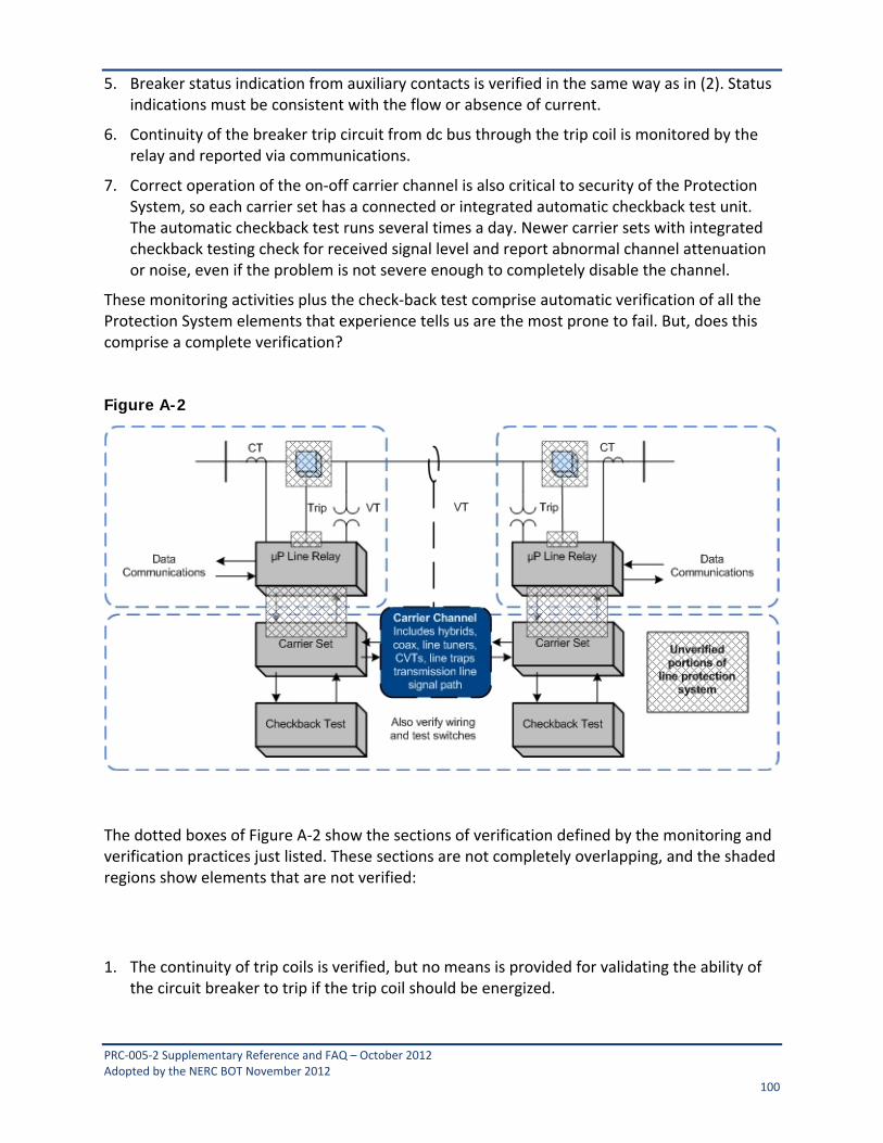
PRC‐005‐2 Supplementary Reference and FAQ – October 2012 Adopted by the NERC BOT November 2012 100
5. Breaker status indication from auxiliary contacts is verified in the same way as in (2). Status indications must be consistent with the flow or absence of current.
6. Continuity of the breaker trip circuit from dc bus through the trip coil is monitored by the relay and reported via communications.
7. Correct operation of the on‐off carrier channel is also critical to security of the Protection System, so each carrier set has a connected or integrated automatic checkback test unit. The automatic checkback test runs several times a day. Newer carrier sets with integrated checkback testing check for received signal level and report abnormal channel attenuation or noise, even if the problem is not severe enough to completely disable the channel.
These monitoring activities plus the check‐back test comprise automatic verification of all the Protection System elements that experience tells us are the most prone to fail. But, does this comprise a complete verification? Figure A-2
The dotted boxes of Figure A‐2 show the sections of verification defined by the monitoring and verification practices just listed. These sections are not completely overlapping, and the shaded regions show elements that are not verified:
1. The continuity of trip coils is verified, but no means is provided for validating the ability of the circuit breaker to trip if the trip coil should be energized.
PRC‐005‐2 Supplementary Reference and FAQ – October 2012 Adopted by the NERC BOT November 2012 101
2. Within each line relay, all the microprocessors that participate in the trip decision have been verified by internal monitoring. However, the trip circuit is actually energized by the contacts of a small telephone‐type "ice cube" relay within the line protective relay. The microprocessor energizes the coil of this ice cube relay through its output data port and a transistor driver circuit. There is no monitoring of the output port, driver circuit, ice cube relay, or contacts of that relay. These components are critical for tripping the circuit breaker for a Fault.
3. The check‐back test of the carrier channel does not verify the connections between the relaying microprocessor internal decision programs and the carrier transmitter keying circuit or the carrier receiver output state. These connections include microprocessor I/O ports, electronic driver circuits, wiring, and sometimes telephone‐type auxiliary relays.
4. The correct states of breaker and disconnect switch auxiliary contacts are monitored, but this does not confirm that the state change indication is correct when the breaker or switch opens.
A practical solution for (1) and (2) is to observe actual breaker tripping, with a specified maximum time interval between trip tests. Clearing of naturally‐occurring Faults are demonstrations of operation that reset the time interval clock for testing of each breaker tripped in this way. If Faults do not occur, manual tripping of the breaker through the relay trip output via data communications to the relay microprocessor meets the requirement for periodic testing.
PRC‐005 does not address breaker maintenance, and its Protection System test requirements can be met by energizing the trip circuit in a test mode (breaker disconnected) through the relay microprocessor. This can be done via a front‐panel button command to the relay logic, or application of a simulated Fault with a relay test set. However, utilities have found that breakers often show problems during Protection System tests. It is recommended that Protection System verification include periodic testing of the actual tripping of connected circuit breakers.
Testing of the relay‐carrier set interface in (3) requires that each relay key its transmitter, and that the other relay demonstrate reception of that blocking carrier. This can be observed from relay or DFR records during naturally occurring Faults, or by a manual test. If the checkback test sequence were incorporated in the relay logic, the carrier sets and carrier channel are then included in the overlapping segments monitored by the two relays, and the monitoring gap is completely eliminated.

PRC‐005‐2 Supplementary Reference and FAQ – October 2012 Adopted by the NERC BOT November 2012 102
Appendix B
Protection System Maintenance Standard Drafting Team Charles W. Rogers
Chairman Consumers Energy Co.
John B. Anderson Xcel Energy
Al McMeekin NERC
Merle Ashton Tri‐State G&T
Michael Palusso Southern California Edison
Bob Bentert Florida Power & Light Company
Mark Peterson Great River Energy
Forrest Brock Western Farmers Electric Cooperative
John Schecter American Electric Power
Aaron Feathers Pacific Gas and Electric Company
William D. Shultz Southern Company Generation
Sam Francis Oncor Electric Delivery
Eric A. Udren Quanta Technology
Carol Gerou Midwest Reliability Organization
Scott Vaughan City of Roseville Electric Department
Russell C. Hardison Tennessee Valley Authority
Matthew Westrich American Transmission Company
David Harper NRG Texas Maintenance Services
Philip B. Winston Southern Company Transmission
James M. Kinney FirstEnergy Corporation
David Youngblood Luminant Power
Mark Lucas ComEd
John A. Zipp ITC Holdings
Kristina Marriott ENOSERV