supplementary material implementation details of the
TRANSCRIPT

SUPPLEMENTARY MATERIAL
Implementation Details of the Sample ApplicationUsing the Proposed Hybrid Terrain Representation
Cetin Koca and Ugur Gudukbay∗
Department of Computer EngineeringBilkent University
Bilkent, 06800, Ankara, Turkey
1. Introduction
We have developed a sample application for:
• creating and editing terrains,• analyzing the memory usage of the proposed terrain representation in typical use cases,• analyzing the performance of the proposed algorithms, and• evaluating the visual quality of real-time terrain rendering obtained by using the pro-
posed rendering pipeline.
The application is implemented in C++ using OpenGL (Silicon Graphics, Inc. 2012b),OpenGL Shading Language (GLSL) (Silicon Graphics, Inc. 2012a), OpenGL ExtensionWrangler Library (GLEW) (Ikits and Magallon 2012), The Developer’s Image Library(DevIL) (Woods et al. 2012), and FreeType (Turner et al. 2012). We provide the imple-mentation details and algorithms used in the sample application, as well as a discussionof how the proposed approach performs compared to heightmap- and voxel-based ap-proaches, in the following sections.
2. Sample Application
The user can generate and edit terrains in real time:
(1) Generate a coarse volumetric representation of the terrain outlining all volumetricfeatures.
(2) Edit the terrain surface and apply fine details at an increased resolution over thecoarse model by modifying heightmaps.
An overview of the terrain geometry generation process, which is a combination of thesurface extraction and surface generation phases, is depicted in Figure 1.
∗Corresponding author. Email: [email protected]

2 Cetin Koca and Ugur Gudukbay
Figure 1. Overview of the terrain geometry generation.
2.1. Terrain Editor
2.1.1. Generating the Coarse Terrain Model
The coarse model is represented by voxels, which are stored in an octree. The model canbe edited manually by selecting a specific voxel at a specific level of the octree and settingwhether the voxel is occupied or not. It can also be automatically generated, entirely orpartly, from a heightmap. After the heightmap is converted to the voxel model, the modelcan then be edited manually to create volumetric terrain features.
To generate the coarse model from the heightmap, the heightmap is first divided intoblocks, depending on the desired resolution. Then the average height of each block iscomputed. A set of voxels lined up along the y-axis corresponds to each heightmap block.Those below the average height are set as occupied while the others remain empty. Thisvoxel model can then be carved manually to generate volumetric terrain features, suchas a cave.
The voxel editor lets the user to select the level of octree at which she or he wantsto operate. Then the position of the cursor is used to compute a ray through the scene;the closest voxel at the selected level that intersects the ray is highlighted. That voxelcan then be set as occupied or empty (see Figure 2). Changing the occupation statusof a voxel at lower levels to occupied automatically increases the level of the octree atthat branch by creating a child at each higher level. Changing the status of a voxel at ahigher level removes its subtrees because that space can now be entirely represented bya single voxel.
2.1.2. Editing the Terrain Surface
A user can edit the terrain surface by deforming the heightmaps. Each voxel is associ-ated with a certain number of patches, depending on the voxel configurations. Oncea voxel is selected, the associated patches can be edited by editing the associatedheightmap. A heightmap is always displayed as a 2D square texture on the user in-

Implementation Details of the Sample Application . . . 3
Figure 2. Manual editing of a voxel model, where the highlighted voxel is shown as a red box.Left: the highlighted voxel is empty. Right: the highlighted voxel is occupied.
terface to allow simple editing operations. The patch on which the heightmap is applied,on the other hand, can have different shapes and orientations. The mapping betweenthe heightmap and the patch can sometimes be unintuitive; to help the user understandwhich part of the heightmap corresponds to which patch, the edges of the heightmap andthe wireframe skeleton rendered on the selected patch are colored accordingly (see Fig-ure 3).
Figure 3. The terrain surface can be edited by modifying the heightmap applied to it. Left: theheightmap applied. Right: the patch being edited.
The heightmap can be edited using different types of brushes, and changes are imme-diately reflected on the patch.
An extrude brush elevates the terrain. It has the following three parameters:
• Radius defines the effective radius of the brush, such that the heightmap pixels outsideit will not be affected.
• Strength determines how the brush effect will diminish as it is applied to pixels fartheraway from the application position.
• Displacement factor determines the magnitude of the displacement applied by thebrush. If the displacement factor is positive, the vertices are displaced along the di-rection of the displacement normals; otherwise, they are displaced in the oppositedirection.
It is usually preferable that the effectiveness of the brush drops as it is applied to pixelsfarther from the center of the application region. We use a sigmoid function (Equation 1)to compute brush effectiveness at a given distance; r is the radius of the brush, s is thestrength, and d is the distance from the pixel to the brush application position. Theconstant δ (equal to 20 in the application) is used to convert the distance between

4 Cetin Koca and Ugur Gudukbay
normalized pixel coordinates on the image space into a distance comparable to the brushradius. Figure 4 demonstrates the effectiveness functions for two brushes with differentstrengths.
tanh(x) = e2x−1e2x+1
f(d) = tanh((r − d × δ) × s
) (1)
Figure 4. Sigmoid function used to compute the effectiveness of a brush at a particular distance.Blue: a brush with radius r = 3 and strength s = 0.5. Red: a brush with radius r = 3 andstrength s = 2.
A smoothing brush smooths the terrain, and it also has three parameters: radius,strength, and smoothing factor. The radius and strength are the same as for the ex-trude brush. The smoothing factor determines how aggressively the smoothing operationis to be performed; if the factor is large, patch roughness is quickly smoothed out.
A noise brush applies noise. We use 3D Simplex noise Gustavson (2005), where theinput to the noise function is the actual world coordinates of the vertices that correspondto the edited pixels of the heightmap. Because these coordinates are continuous thecontinuity of the 3D surface is guaranteed.
2.2. Rendering Pipeline
The rendering pipeline (see Figure 5) is implemented by programming the GPU usingcustom vertex and fragment shaders. It has four major stages:
(1) Vertex buffer updates (green in the figure),(2) Index buffer updates (red in the figure),(3) Generating shadow maps (blue in the figure), and(4) Terrain surface rendering (orange in the figure).
2.2.1. Vertex Buffer Updates
The proposed approach uses vertex buffers to store vertex attributes such as vertexposition, vertex normal, and geometry morphing parameters. The buffers are stored inthe video memory because:

Implementation Details of the Sample Application . . . 5
Figure 5. Rendering pipeline used in the sample application.
• GPU access to data in the vertex buffers is extremely fast and• data stored in the main memory does not need to be transferred to the GPU in each
frame, thus avoiding a CPU-to-GPU data-transfer bottleneck.
The vertex buffers are populated once the terrain surface is generated and ready forrendering. As long as the terrain surface is not deformed, vertex buffers do not need tobe updated. When the terrain surface is deformed, the vertex attributes affected by thedeformation must be updated with the data in the main memory.
Static Surface Culling. The surface extraction algorithm generates patches consideringeach voxel intersection volume. Because the algorithm is designed to generate connectedand continuous surfaces, it can generate patches that will never be seen in practice. Whena patch is generated, its control points are checked against the axis-aligned bounding boxof the terrain model to determine whether the patch is redundant, i.e., when all controlpoints are either on the bottom face or one of the side faces of the bounding box. If so,the patch is discarded. As a result of this process, although the extracted surface may nolonger be connected, the visible part of the surface is still continuous. Our experimentshave shown that about 40% to 55% of generated patches can be discarded. Figure 6shows the result of static surface culling where the number of generated patches is 8,962without culling and 3,948 with culling.
2.2.2. Index Buffer Updates
Index buffers are also stored in the video memory but they contain vertex connectivityinformation, that is, how the vertices should be connected to form triangles. The indexbuffer is the actual list of primitives to be rendered by the GPU; thus, the number ofprimitives represented by the index buffer determines the rendering performance. Forthis reason, the index buffer is updated at each frame, when the frustum culling and

6 Cetin Koca and Ugur Gudukbay
Figure 6. The result of static surface culling. Redundant surfaces are tinted with brown. Left:without static surface culling. Right: with static surface culling.
LOD functions are executed.The algorithm that updates the index buffer operates on the octree. Each node of
the octree is first checked to see whether its terrain surface bounding box is completelyoutside the frustum. If it is, then the subtree of that node is eliminated from furtherprocessing because it does not contribute to the rendering process. The patch LODs as-sociated with the voxels that pass the frustum test are then computed. The correspondingtriangle vertex index data of these patches are copied to the index buffers.
Frustum Culling. It is not possible to use voxels in frustum checks because the displacedterrain surfaces may overflow the voxel limits. For frustum culling, a hierarchy of surfacebounding boxes is computed and then stored in the octree in a bottom-up fashion. Thebounding boxes for the leaf nodes are computed by using the patches assigned to them.Then, the bounding box of each higher-level node is computed recursively by taking theunion of the child node bounding boxes. When a patch is deformed, the bounding boxesof all octree nodes on the path from the leaf node that contains the deformed patch tothe root are updated. This is not an expensive operation because the octree depth is notvery high.
Frustum culling must be repeated whenever the view frustum changes. When fourcascaded shadow maps are used, frustum culling is done four times for rendering theshadow maps and again for rendering the actual terrain surface at each frame. Frustumculling helps improve rendering performance even when it is repeated multiple times perframe.
2.2.3. Generating Shadow Maps
The terrain surface geometry is rendered once for each cascaded shadow map. Thevertex and fragment shaders used to render shadow maps are relatively simple: Theformer computes the distance from the vertex to the observer and applies geometrymorphing to the vertex. It then multiplies the computed world coordinate with themodel-view-projection matrix of the light to compute the coordinates of the projectedfragment. The latter then takes the z-coordinate of the fragment, adds an offset to it toprevent z-fighting, and writes the computed value to the shadow map.
2.2.4. Terrain Surface Rendering
Once the shadow maps are generated, the actual rendering can be done using theterrain surface geometry, shadow maps, and other textures. The vertex shader performsthe following tasks:
• Normalizes vertex normals. Doing this on the GPU improves performance when theterrain surface is constantly being updated (e.g., during terrain editing).
• Computes the distance from the vertex to the observer.

Implementation Details of the Sample Application . . . 7
• Computes the LOD transition position of the vertex using the distance to the observer.• Computes the LOD transition normal of the vertex using the distance to the observer.• Projects the world coordinate of the vertex into the eye space by multiplying it by the
view-projection matrix of the perspective camera.
The fragment shader performs the following tasks:
• Normalizes the interpolated normals because interpolating between two normalizednormals does not always result in a normalized normal.
• Computes tri-planar texture coordinates.• Computes Simplex noise values for use in multi-texturing.• Applies multi-texturing and texture splatting.• Performs per-pixel directional lighting computations.• Performs per-pixel point light computations for each point light in the scene.• Samples shadow maps several times and blends them using Gaussian filtering.• Blends the color values computed in the texturing, lighting, and shadowing phases to
compute the final pixel color.
3. Algorithms and Data Structures
3.1. Data Structures
Our approach uses an octree to store the volumetric representation to develop a compactrepresentation by exploiting large groups of occupied and empty voxels. The root nodeencloses the entire terrain. Each octree node can be divided into eight equal-sized axis-aligned child nodes if extra LOD subspace is needed (see Figure 7 (a)).
Figure 7. (a) Adaptive octree representation can increase resolution where needed. (b) Voxelindices for the adaptive octree representation (voxel level, x-index, y-index, z-index) at lev-els 1 and 2. Index fields are binary.
One of the most important advantages of an octree is its efficiency in running differentqueries on the geometry in an hierarchical manner. This feature is used by terrain editorsand we use it for voxel selection and manipulation in our terrain editor. It can alsosignificantly speed up collision queries, culling queries, and LOD queries, especially inreal-time applications.

8 Cetin Koca and Ugur Gudukbay
3.1.1. Voxel Structure
Each voxel has an index associated with it, which is stored in memory with the voxel(see Figure 7 (b)). Voxel size depends only on the level at which the voxel resides becausethe octree volume is divided by 2 at each axis at each level increment. The position of avoxel is defined as the centre of the voxel. At each level, a voxel’s position is displacedalong each axis by an amount equal to half the voxel size at that level in that axis,depending on whether the value of the index field for that level is 0 or 1; displacementis applied through the negative or positive side of the corresponding axis, respectively.
A voxel index is represented using four bytes in memory:
(voxel level, x-index, y-index, z-index )(four bits, nine bits, nine bits, nine bits)
The voxel index structure uses a total of 31 bits of the four bytes. The final bit isused to store the information of whether the voxel is occupied or empty. This bit is notused if the index points to a voxel. A voxel index stored in this format allows up to nineadditional levels other than the root level because the index fields are stored in nine bits.Consequently, the maximum height of an octree that uses this representation cannotexceed 10. An octree of height 10 has over one billion leaf nodes. In practice, an octreeof height 5 or 6 provides enough resolution for most terrains. The voxel level indicatesthe distance from a voxel to the root of the octree.
The x-, y- and z-index fields store the index of the voxel on the x-, y- and z-axes,respectively. The i-th bit of these fields determines whether the voxel is the first or thesecond child of the parent voxel in the (i− 1)-st level of the octree on the correspondingaxis. The most significant bits of each field are considered: the first bits of the fieldsrepresent the child selection at level 0, the second bits represent the child selection atlevel 1, and so on. The number of meaningful bits in these fields is determined by thevoxel level. If the voxel level is 1, then only the first bits of each field are meaningfulbecause the child selection is done only on level 0. Figure 8 illustrates the computationof the x- and y-coordinates of a voxels position at level 3 from its voxel index.
Figure 8. Computing the x- and y-coordinates of a voxel’s position at level 3 from its voxel index(an xy-cross section of the voxel space is depicted).

Implementation Details of the Sample Application . . . 9
Our voxel index representation has some advantages over traditional memory pointers:
• It takes up as much space as a memory pointer but stores additional information: thelevel of the voxel in the octree.
• Given a voxel index, the index of the parent voxel can be computed just by decrement-ing the value of the voxel level by 1.
• Given a voxel index, the index of child voxels can be computed by incrementing thevoxel level by 1 and setting the i-th bit of each index field to 0 or 1, where i is equalto the incremented voxel level.
• Given a voxel index, the index of neighbor voxels at the same level can be computedby incrementing, decrementing, or keeping same the values of each index field. Thereare three possible operations (increment, decrement, and keep value) that can be per-formed on three index fields to compute the voxel index of 26 neighbor voxels.
• It simplifies the implementation of algorithms that work on the octree; it can be usedto iterate voxels and move to neighbor voxels; a memory pointer can only be used toaccess data.
• It also saves memory space because voxel size and position can be computed given thevoxel index, preventing the need to store this information.
3.1.2. Patch Structure
We choose Bezier surfaces as the underlying patch representation. Bezier curves (andsurfaces) have several useful properties, such as endpoint interpolation, invariance un-der affine transformations and translations, lying within the convex hull of their controlpoints, and computational efficiency when subdividing compared to other representa-tions, such as non-uniform rational basis splines. It is possible to obtain first-order (C1)continuity on the boundaries of two neighboring Bezier curves (thus patches) by aligningthe last two control points of the first curve with the first two control points of the secondcurve.
Each patch has the following attributes stored in the main memory:
• A number of control points that define the surface of the patch.• A vertex buffer that stores the vertices approximating the surface of the patch.• An index buffer that stores the vertex indices in a particular order so as to generate
the triangle list for rendering the patch.• A heightmap associated with the patch to be used as a displacement map.• Pointers to linked lists for vertices that are shared with other patches.• Up to four pointers to neighbor patches with coinciding edges.
3.1.3. Vertex Structure
Vertex representation in the main memory stores the following attributes:
• Original vertex position as a 3D floating point vector (12 bytes).• Displacement normal as a 3D floating point vector (12 bytes). This defines the direction
of displacement.• Displaced vertex position as 3D floating point vector (12 bytes). This is computed by
moving the vertex in the direction of the displacement normal by an amount deter-mined by the corresponding heightmap value.
• Actual vertex normal as a 3D floating point vector (12 bytes). This is the vertex normalcomputed after all displacement operations are performed. It is used for texturing andlighting computations.

10 Cetin Koca and Ugur Gudukbay
• Color of the vertex as a 4D floating point vector (16 bytes). Color can be applied asa post-processing effect on the color obtained from textures. It can also be used tohighlight some parts of the terrain.
• LOD transition distance of the vertex as a single floating point number (four bytes).It determines the distance at which the LOD management algorithm will move thevertex into a lower LOD position.
• Pointers to two neighbor vertices at a lower LOD (eight bytes). These vertices areaccessed to compute the lower LOD transition position and normal of the currentvertex when the vertex data is to be sent to the video memory.
• Index of the vertex in the GPU vertex buffers as an unsigned integer (four bytes). Thisis a pointer to the vertex data stored in the video memory; it is used to update thatdata whenever the data in the main memory is updated. The most significant bit ofthis field is used as a flag to indicate whether the vertex normal is invalidated andneeds to be recomputed; i.e., when the heightmap values are modified.
Vertex representation in the video memory stores the following attributes:
• Position of the vertex as a 3D floating point vector (12 bytes).• Normal of the vertex as a 3D floating point vector (12 bytes).• Color of the vertex compressed to a 4D unsigned byte vector (four bytes).• Lower LOD transition position of the vertex as a 4D floating point vector (16 bytes).
The w-component of this (x, y, z, w)-vector stores the transition distance.• Lower LOD transition normal of the vertex as a 3D floating point vector (12 bytes).
3.2. Vertex Index Calculation
The presented approach does not require explicitly storing triangle vertex indices. Algo-rithm 1 computes triangle vertex indices on the fly with the help of a static lookup table.It should be noted that each vertex is shared by multiple triangles; not only by thosebelonging to the same patch but also by triangles of different patches (through sharedvertex lists). It is now possible to render the terrain surface using a hardware-acceleratedrasterization-based renderer by sending the vertices to the GPU and using triangles asthe rendering primitive.
3.2.1. Surface Generation
Algorithm 2 finds out the virtual sub-voxels on which the surface extraction algorithmwill work by handling voxel level transitions. Algorithm 2 calls the surface extractionalgorithm (Algorithm 3) for each virtual sub-voxel.
Algorithm 3 generates surface patches for a single intersection volume. The gener-ated surfaces are added to the list of Bezier surfaces stored in one of the voxels in thecorresponding volume. We store surfaces generated in the voxel whose index fields haveminimum values. Where they are stored does not matter as long as the choice is consistentand it ensures that the adjacent voxels store the surfaces for the adjacent volumes.

Implementation Details of the Sample Application . . . 11
Algorithm 1: Generating triangle vertex indicesgenerateTriangleVertexIndices(triangleIndex,
numVerticesPerEdge, vertexIndices);triangleIndex : (input) Zero-based index of the trianglenumVerticesPerEdge: (input) Number of vertices per edge (N)vertexIndices : (output) Vertex indices of the triangle
beginconst indices[8][3][2] = {{ {0, 0}, {0, 1}, {1, 1} }, // face-1{ {1, 1}, {0, 1}, {0, 2} }, // face-2{ {0, 2}, {1, 2}, {1, 1} }, // face-3{ {1, 1}, {1, 2}, {2, 2} }, // face-4{ {2, 2}, {2, 1}, {1, 1} }, // face-5{ {1, 1}, {2, 1}, {2, 0} }, // face-6{ {2, 0}, {1, 0}, {1, 1} }, // face-7{ {1, 1}, {1, 0}, {0, 0} }, // face-8
};// % is the modulus operator; << is the left-shift operator;// >> is the right-shift operator; & is the bitwise-and operator.
numFacesPerEdge = numVerticesPerEdge >> 1;
i = (batchIndex % numFacesPerEdge) << 1;j = (batchIndex / numFacesPerEdge) << 1;k = triangleIndex & 0x7;
for v ← 0 to 3 dovertexIndices← (i + indices[k ][v ][0], j + indices[k ][v ][1]);
Algorithm 2: Generating surfaces for sub-voxel intersection volumes by handlingvoxel level transitionsgenerateSubVoxelSurfaces(root, patchCollection)root : (input) The root of the voxel representationpatchCollection: (output) The list of Bezier surface patches
beginif root has children then
// construct patches for each childfor i← 0 to 8 do
generateSubVoxelSurfaces(root.getChildVoxel(i), patchCollection);
return;
rootVoxelIndex = root.getIndex();levelDiff = maxLevel - rootVoxelIndex.level ;
// << is the left-shift operator and | is the bitwise-or operatornumSubVoxelsPerAxis = 1 << levelDiff ;maxSubVoxelIndexPerAxis = (1 << (levelDiff )) - 1;
for x← 0 to numSubVoxelsPerAxis dofor y ← 0 to numSubVoxelsPerAxis do
for z ← 0 to numSubVoxelsPerAxis do
// skip vertices that are not on surface of voxelif ((x ! = 0 and x ! = maxSubVoxelIndexPerAxis) and
(y ! = 0 and y ! = maxSubVoxelIndexPerAxis) and(z ! = 0 and z ! = maxSubVoxelIndexPerAxis)) thencontinue;
// compute voxel index of virtual child voxelsubVirtualVoxelIndex.level = maxLevel ;subVirtualVoxelIndex.xIndex = (rootVoxelIndex.x << levelDiff ) | x;subVirtualVoxelIndex.yIndex = (rootVoxelIndex.y << levelDiff ) | y;subVirtualVoxelIndex.zIndex = (rootVoxelIndex.z << levelDiff ) | z;// construct patches for the virtual child voxelsgenerateSurfacePatches(voxelIndex, patches);patchCollection.addPatches(patches);

12 Cetin Koca and Ugur Gudukbay
Algorithm 3: Generation of patches for a single voxelgenerateSurfacePatches(voxelIndex, patches)voxelIndex : (input) The index of the voxel for which the surface patches will be generatedpatches : (output) The list of surface patches, stored per voxel
begin
// construct the voxel intersection volumevoxelIndices[8];for i← 0 to 8 do
// >> is right-shift and % is modulusvoxelIndices[i] = getNeighborVoxelIndex(i >> 2, (i >> 2) % 2, i % 2);
// normalize voxel intersection volumenormalizedVoxelGroups = normalize(voxelIndices);
foreach voxelGroup in normalizedVoxelGroups do
occupyFlag = 0;
for i← 0 to 8 do// | = is bitwise-or assignment and << is left-shiftoccupyFlag | = voxelGroup.isVoxelOccupied(i) << i;
patches = computeControlPoints(occupyFlag);
voxel = getVoxel(voxelIndex);
foreach patch in patches dovoxel.patches← patch;
3.3. Displacement of Terrain Vertices
The displacement operation is performed on each vertex of all patches. However, dueto shared vertices among patches, displacement may be applied multiple times on somevertices. To avoid this, we introduce the concept of vertex owners for externally sharedvertices. The owner is the patch pointed to by the first node of the shared vertex list ofthat vertex. Displacement is applied on externally shared vertices only by the patch thatowns the vertex.
The displacement operation can also occur multiple times on internally shared vertices,as multiple vertex indices can point to the same vertex if an edge of the patch is collapsed.In this case, displacement must be applied to only the first vertex index that points tothe internally shared vertex. All other vertex indices that point to an internally sharedvertex are called inactive indices, and displacement is not applied.
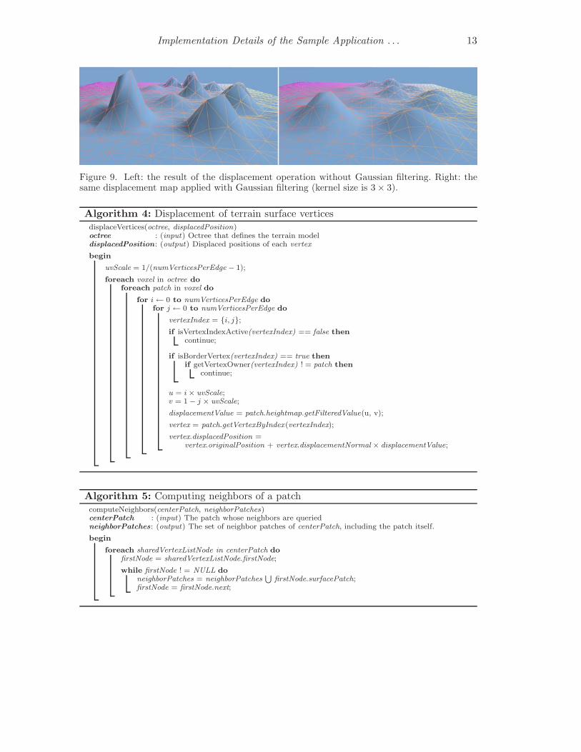
The displacement values of neighbor vertices should be similar to avoid jagged edgesand sharp corners. To generate a smooth terrain surface, a Gaussian filter is applied whilecomputing displacement values. Kernel size dramatically affects the resulting terrain: alarge kernel size will over-smooth the surface by removing fine details and slow down thedisplacement operation, whereas a small kernel size will not be sufficiently effective inreducing jagged edges and corners. Our experiments have shown that a Gaussian kernelof size 3 × 3 usually yields sufficiently good results (see Figure 9).
Algorithm 4 applies displacement to the terrain surface vertices. Algorithm 5 finds theneighbor patches of the modified patch; Algorithm 6 updates the displaced positions ofthe vertices of the modified patch; and Algorithm 7 updates the vertex normals affectedby the surface modification.
Implementation Details of the Sample Application . . . 13
Figure 9. Left: the result of the displacement operation without Gaussian filtering. Right: thesame displacement map applied with Gaussian filtering (kernel size is 3 × 3).
Algorithm 4: Displacement of terrain surface verticesdisplaceVertices(octree, displacedPosition)octree : (input) Octree that defines the terrain modeldisplacedPosition: (output) Displaced positions of each vertex
begin
uvScale = 1/(numVerticesPerEdge − 1);
foreach voxel in octree doforeach patch in voxel do
for i← 0 to numVerticesPerEdge dofor j ← 0 to numVerticesPerEdge do
vertexIndex = {i, j};if isVertexIndexActive(vertexIndex) == false then
continue;
if isBorderVertex(vertexIndex) == true thenif getVertexOwner(vertexIndex) ! = patch then
continue;
u = i× uvScale;v = 1− j × uvScale;
displacementValue = patch.heightmap.getFilteredValue(u, v);
vertex = patch.getVertexByIndex(vertexIndex);
vertex.displacedPosition =vertex.originalPosition + vertex.displacementNormal × displacementValue;
Algorithm 5: Computing neighbors of a patchcomputeNeighbors(centerPatch, neighborPatches)centerPatch : (input) The patch whose neighbors are queriedneighborPatches: (output) The set of neighbor patches of centerPatch, including the patch itself.
begin
foreach sharedVertexListNode in centerPatch dofirstNode = sharedVertexListNode.firstNode;
while firstNode ! = NULL doneighborPatches = neighborPatches
SfirstNode.surfacePatch;
firstNode = firstNode.next;

14 Cetin Koca and Ugur Gudukbay
Algorithm 6: Updating the displaced positions of verticesupdateDisplacedPositions(modifiedPatch, displacedPosition)modifiedPatch : (input) The patch whose heightmap is modifieddisplacedPosition: (output) Displaced positions of vertices
begin
uvScale = 1/(numVerticesPerEdge − 1);
foreach vertex in modifiedPatch dovertexIndex = vertex.vertexIndex;
if isVertexIndexActive(vertexIndex) == false thencontinue;
if isBorderVertex(vertexIndex) == true thenif getVertexOwner(vertexIndex) ! = patch then
continue;
u = vertexIndex.i× uvScale;v = 1− vertexIndex.j × uvScale;
displacementValue = patch.heightmap.getFilteredValue(u, v);vertex.displacedPosition = vertex.originalPosition +
vertex.displacementNormal × displacementValue;
// invalidate the vertex normalvertex.recomputeNormal = 1;// reset the vertex normalvertex.actualNormal = {0, 0, 0};
Algorithm 7: Updating the affected vertex normals after editing a surface patch’sheightmapupdateNormals(modifiedPatch, actualNormal);modifiedPatch: (input) Surface patch whose heightmap is modifiedactualNormal : (output) Updated normals of affected vertices
begin
neighborPatches = getNeighboringPatches(modifiedPatch);foreach patch in neighborPatches do
foreach triangle in patch doforeach vertex in triangle do
if vertex.recomputeNormal == 1 thentriangle.recomputeNormal = 1;
foreach patch in neighborPatches doforeach triangle in patch do
if triangle.recomputeNormal == 0 thencontinue;
foreach vertex in triangle dovertex.recomputeNormal = 1;
foreach patch in neighborPatches doforeach triangle in patch do
vertices = triangle.vertices;
if ((vertices[0].recomputeNormals == 0) and(vertices[1].recomputeNormals == 0) and(vertices[2].recomputeNormals == 0)) thencontinue;
−→v1 = vertices[1] - vertices[0]−→v2 = vertices[2] - vertices[1]−→N = −→v1 ×−→v2
for i← 0 to 3 doif vertices[i].recomputeNormals == 1 then
vertices[i].actualNormal +=−→N

Implementation Details of the Sample Application . . . 15
3.4. Voxel Selection Ray Computation for Generating the CoarseTerrain Model
Computing the voxel selection ray that is used in generating the coarse terrain model isperformed by a number of transformations applied to the 2D cursor position. Algorithm 8computes that ray, given the cursor’s coordinates, and it is then used to determine theclosest intersecting voxel at the desired level of the octree.
Algorithm 8: Computing the start and end positions of the ray in world coordinatesdefined by the cursorcomputeRay(cursorPos, viewport, camera, rayStart, rayEnd)cursorPos: (input) 2D cursor position on application viewportviewport : (input) Viewport attributes used for renderingcamera : (input) Perspective camera attributes for renderingrayStart : (output) Starting ray position in world coordinatesrayEnd : (output) Ending ray position in world coordinates
begin
// compute normalized cursor coordinatesnormalizedCursorX = (cursorPos.X / viewport.width) × 2 - 1;normalizedCursorY = 1 - (cursorPos.Y / viewport.height) × 2;
if viewport.width > viewport.height thennormalizedCursorX *= viewport.width / viewport.height;
elsenormalizedCursorY *= viewport.height / viewport.width;
// the field of view is in radiansfovFactor = tan(camera.fieldOfView× 0.5);normalizedCursorX = normalizedCursorX × fovFactor;normalizedCursorY = normalizedCursorY × fovFactor;
// compute the starting position of the rayrayStart = {
normalizedCursorX × camera.nearClipDistance,normalizedCursorY × camera.nearClipDistance,-camera.nearClipDistance, 1};
// compute the ending position of the rayrayEnd = {
normalizedCursorX × camera.farClipDistance,normalizedCursorY × camera.farClipDistance,-camera.farClipDistance, 1};
// transform ray definition into world spaceinverseViewMatrix = inverse(camera.viewMatrix);rayStart = inverseViewMatrix× rayStart;rayEnd = inverseViewMatrix× rayEnd;
4. Discussion
We discuss how the proposed approach performs compared to heightmap- and voxel-based approaches.
Expressiveness is defined as the ability to create interesting terrain features using aterrain representation. A heightmap samples the terrain in 2D, hence it has limited ex-pressive power. It is not possible to represent volumetric terrain features such as caves,overhangs, arches, and even vertical cliffs using heightmaps; voxel-based representations,on the other hand, sample the true 3D space surrounding the terrain. With an infinites-imal voxel size, we can represent all possible terrains, and any other 3D object for thatmatter. Increasing voxel resolution, however, has serious practical implications such ashigh memory usage.

16 Cetin Koca and Ugur Gudukbay
The proposed hybrid approach is a combination of voxel and heightmap representationsin terms of expressiveness. It converges to a voxel representation as the resolution of thecoarse voxel model increases, and converges to a heightmap representation as it decreases.However, it is not possible to render high-resolution voxel models in real time anyway. Toincrease overall efficiency, the proposed approach provides high voxel resolution wherevolumetric features are dense and complex, and benefits from the simplicity of heightmapapproaches where such features are redundant.
Simplicity of the algorithms is important. Heightmaps and their algorithms are simple.Using voxels to represent volumes is also simple. It is possible to write simple algorithmsthat work on voxel data, however, it is not plausible to use them for real-time applications.Voxel data is usually huge, which increases algorithm complexity: they must page datain and out of the memory, generate relevant parts of the surface from the voxel modelat every frame, compress and decompress voxel data, etc. Our approach is a heightmaprepresentation applied on a coarse voxel model; we can thus use existing algorithms forheightmap-based regular grid representations with only minimal changes.
Efficiency is necessary in the processing and memory usage demanded by real-timeterrain rendering. Heightmaps are unbeatable in this respect. Their memory requirementsare extremely low, even for very large terrains, because almost all vertex attributes areimplicit, making it redundant to store them. Given any heightmap, a GPU can efficientlycreate the entire geometry, including attributes such as vertex normals. One of our designgoals was to benefit from the simplicity and efficiency of heightmap representations, andthus the terrain surface in our approach is similar to a regular grid heightmap surface. Ourapproach is obviously not as efficient as heightmaps are, but it is much more expressive,and in terms of memory usage and demanded processing power, it is efficient enough fora real-time terrain rendering application.
Voxel-based terrain representations usually require high amounts of memory when theyare stored uncompressed and at a high resolution. Memory efficiency can be increased atthe cost of processing power by compressing and decompressing the voxel representationas needed, but this is difficult in a real-time rendering application. Voxel representationscannot be directly used for rendering, and unlike heightmaps, the polygonal surface of avoxel model cannot be easily generated. Doing this in real-time and at every frame, suchas for LOD and culling algorithms, is even more difficult. As a result, voxel representa-tions are not popular in real-time applications.
Visual quality depends on methods used for lighting, texturing, and shadowing. It iseasy to generate the terrain surface of a heightmap without visual artifacts; LOD manage-ment is also easy because the terrain surface is greatly constrained and the connectionsbetween vertices are well defined and simple.
Generating a polygonal surface for a volumetric representation is not easy. Relativelysimple methods, such as the original marching cubes, may generate visual artifacts. LODmanagement is problematic because most surface extraction methods do not support asampling grid with different resolutions in different areas. Even methods that use an LODapproach (e.g., Lengyel (2010)) cannot support smooth LOD transitions and the visualquality is thus significantly degraded. Using patches, our surface extraction method cangenerate a smooth terrain surface for a coarse volumetric representation with no artifacts.Our LOD approach supports smooth LOD transitions by geometry morphing.
Content creation can be performed by procedural techniques, manual editing, or acombination of both. Quasi-random terrain data is usually generated by procedural tech-niques, which can be controlled by a set of parameters, and fine details are then added byartists. Creating heightmaps is relatively simple, and procedural techniques to do so are
REFERENCES 17
available. With a heightmap, one can create realistic terrains in a controllable way usingnoise functions and can manually edit them with an image editor or with a specialized3D heightmap terrain editor. However, it is very difficult, if not impossible, to createinteresting terrain features using heightmaps.
Procedural content creation techniques are available for volumetric terrains, but thesecannot easily create volumetric features such as mountains, hills, caves, and arches. Man-ually editing volumetric models requires turning voxels on or off, which necessarily sim-plifies any volumetric features. The proposed representation can support procedural tech-niques for volumetric terrains to create the coarse model and heightmaps to create thesurface details. Manual editing is easy for both representations, but can sometimes beunintuitive due to the displacement normals of the terrain surface. This problem can beovercome by using a terrain editor specifically designed for the proposed representation.
Physics computations for interactions with the terrain (such as collision detection withcreatures and vehicles) are also usually necessary. For some applications, it is desired tomodify the terrain in runtime according to these interactions. Voxel terrain models canbe easily edited by turning voxels on and off. Modifying these models may require regen-eration of the entire surface, however, because most surface extraction approaches do notsupport local updates. Simple physics computations are usually efficient because check-ing whether a voxel is empty or not requires a fast lookup. Performing more advancedphysics computations depends on the structure used to store volumetric data.
Although heightmaps can be easily edited, updates are limited because only vertexheight can be changed. Physics queries such as collision detection are simple because agiven position in the space maps one to four samples on the heightmap, and becauseheightmaps allow limited terrain configurations.
The proposed representation allows deformations at the patch level in real time butthe coarse model cannot be modified in real time. Patch deformations are efficientlyhandled and only cause local changes on the terrain surface. The coarse voxel model cananswer some queries but it is not reliable because it does not take into account heightmapdisplacements applied to patches.
References
Gustavson, S., 2005. Simplex Noise Demystified [online], Available from:http://webstaff.itn.liu.se/~stegu/simplexnoise/simplexnoise.pdf, [Ac-cessed at 19 March 2014].
Ikits, M. and Magallon, M., 2012. GLEW: The OpenGL Extension Wrangler Library [on-line], Available from: http://glew.sourceforge.net/, [Accessed at 19 March 2014].
Lengyel, E., 2010. Voxel-Based Terrain for Real-Time Virtual Simulations. Thesis (PhD).University of California at Davis.
Silicon Graphics, Inc., 2012a. GLSL: OpenGL Shading Language [online], Available from:http://www.opengl.org/documentation/glsl/, [Accessed at 19 March 2014].
Silicon Graphics, Inc., 2012b. OpenGL: Open Graphics Library [online], Available from:http://www.opengl.org/, [Accessed at 19 March 2014].
Turner, D., Wilhelm, R., and Lemberg, W., 2012. The FreeType Project -A Free, High-Quality, and Portable Font Engine [online], Available from:http://freetype.sourceforge.net, [Accessed at 19 March 2014].
Woods, D., Weber, N., and Dario, M., 2012. DevIL - A Full Featured Cross-platformImage Library [online], Available from: http://openil.sourceforge.net/, [Ac-cessed at 19 March 2014].