superprecision ball bearings - sm industrial s.r.l. · pdf filesuperprecision ball bearings. 2...
TRANSCRIPT

ABOUT THE COVERThe Torrington Company is committed to develop,
produce and deliver products and services thatconsistently meet or exceed customer expectations.
Helping The Torrington Company achieve thegoals stated above are our corps of highly trainedsales engineers, the latest analytical and manu-facturing systems, a commitment to research anddevelopment for new ideas and products, ourdevotion to the principles of Total Quality and ahistory steeped in technological firsts in theantifriction industry.
This catalog will help you to design the technol-ogy, quality and service of The Torrington Companyinto your products.
1
©2000 The Torrington Company
Superprecision Ball Bearings

2 102800
FAFNIR SUPERPRECISION BEARINGS
Introduction Pages 4-5
Superprecision Bearings Pages 8-85
Ballscrew Support Bearings Pages 86-100
Engineering Pages E1-E49
Maintenance • Machine Tool Spindles Pages E51-E63
Index Pages E64-E65
CONTENTS

3102800
FAFNIR SUPERPRECISION BEARINGS
See last page of catalog for Engineering Sales Offices
INT
RO
DU
CT
ION
SU
PE
RP
RE
CIS
ION
BE
AR
ING
SB
AL
LS
CR
EW
SU
PP
OR
T B
EA
RIN
GS
EN
GIN
EE
RIN
GM
AIN
TE
NA
NC
E M
AC
HIN
ET
OO
L S
PIN
DL
ES
IND
EX
Forward E52Procedure E52Enclosed Dust-Free Working Area E52Inspection of Parts Before Assembly E52Bearing Packing E53Bearings Assembled in Spindle Mounting E53Bearings and Shaft Assembled with
Eccentricities Opposed E54Scraping Locknut to Eliminate Runout E55
Checking Temperature, Vibrationand Roughness E56
Cleanliness E56-E58Typical Applications of Ball Bearings
to Machine Tool Spindles E58Quick Reference Data Sheets E60-E62Bearing Analysis sheet E63
Forward E2Tolerances E3Standard Tolerances, Inner Ring, ABEC-7,-9 E4Width Tolerances E4Standard Tolerances, Outer Ring, ABEC-7,-9 E5Shaft and Housing Geometry E6Recommended Spindle Shaft Tolerances E8,E9Recommended Spindle Housing Tolerances E10-E15Ball Screw Shaft and Housing
Shoulder Diameters E16Spindle Shaft and Housing
Shoulder Diameters E17-E19
Locknut Torque E22Micron Bore and O.D. Coding E23Lube Inlet Diameters E27Recommended Ball Screw Shaft
and Housing Tolerances E24,E25Typical Mountings of Duplex Bearings E29Back-to-Back vs Face-to-Face Mounting E30Spring-Loaded Mountings E31Preloading E31Bearing Selection E32Bearing Spacers E34
Housing Design E34Housing Seals E35Bearing Locknuts E35Heat Generation E35,E36Permissible Operating Speed E36Lubrication Types E37,E38Engineering Notations E41Life Calculators E41-E43Life Adjustment Factors E43Applications E45-E48Radial Internal Clearance E49
Extra-Light 2MMV9100HX Series 34-41Extra-Light 2MM9100WI, 3MM9100WI Series 42-51Extra-Light MM9100K Series 52-54Light 2MM200WI, 3MM200WI Series 56-65Light MM200K Series 66-68Medium 2MM300WI, 3MM300WI Series 69-77Medium MM300K Series 78-80Ex-Cell-O Spindle Bearings 81-83Hybrid Ceramic Bearings 84,85
The Torrington Company 1The Torrington Commitment 1Fafnir Superprecision Bearings 4Using This Catalog 4Hybrid Ceramic Bearings 5Conditions of Sale 5Warranty 5Liability 5Restricted Applications 5Safety Recommendations 5
Nomenclature Chart 8Superprecision Bearing Introduction 10Machine Tool Offering Chart 11Bearing Types
Angular Contact 12Ballscrew Support Bearings 13
Ultra-Light 2MM9300WI, 3MM9300WI Series 14-23Extra-Light 2MMV99100WN,
3MM99100WN Series 24-33
Nomenclature Chart 86Ballscrew Support Bearings 88-91BSBU D
Standard and Heavy Duty Bearings 92,93BSBU Q
Standard and Heavy Duty Bearings 94,95BSPB D
Standard and Heavy Duty Bearings 96,97BSPB Q
Standard and Heavy Duty Bearings 98,99
CONTENTS
Shelf Life and Storage Policy 6
INTRODUCTION
INTRODUCTIONThe Torrington Company (hereinafter referred to as “Torrington”),part of worldwide Ingersoll-Rand, is a bearing and automotivecomponent supplier of international stature. Its global presence inNorth America, Europe, Australia, South America and the FarEast, plus joint ventures in Japan, The People’s Republic ofChina, and Europe, support customer operations around theworld.
Torrington began manufacturing bearings in the early 1900sand now produces every basic type of precision ground anti-friction bearing, as well as many precision components for othermechanisms. Torrington’s wholly owned subsidiary, KilianManufacturing Corporation, produces lighter duty machinedbearings. Torrington’s merger with Fafnir Bearing, founded in1911 and recognized as one of the world’s major suppliers ofprecision bearings and housed units, has further strengthenedTorrington’s leadership position as a broad line supplier to theworld’s industries.
Torrington’s world leadership position in an automotivecomponent technology is based on its complete technical ability.This extends from the initial design stages through applicationanalysis, to optimizing the entire manufacturing process. Theexperience gained from broad design and manufacturingactivities is available to our customers through Torrington’sresident engineers and field sales engineers in all parts of theworld.
As Torrington enters the 21st century, it has dedicated itscapabilities and resources — its people, facilities, systems andtechnologies — to two goals:
• producing world-class products.• assuring total customer satisfaction.
TORRINGTON IS AT HOME AROUND THE WORLDTo support its sales and service activities, Torrington has:• Over 20 manufacturing plants on five continents.• Over 40 district sales engineering offices throughout the
world.• Warehouses throughout the U.S.A., Canada and Germany,
with interlinking computerized inventory control.• Extensive capabilities in metric and inch bearings.• Technical resources for customer assistance.For new concepts of the future, for the challenges faced by
industry, Torrington offers in-depth design assistance andmultinational supply capability for products that are made toidentical standards worldwide.
USING THIS CATALOGWe are committed to providing our customers with maximumservice and quality. Included in this commitment is a concern forthe suitability of the bearing selected for any application. Onlythose with sufficient engineering training and technical compe-tence to interpret and apply the data and principles involvedshould make the final selection of a bearing. The part number inthis catalog describes only the dimensions. The part number ofthe product supplied may differ than those listed in these pages.
This catalog contains dimensions, tolerances and loadratings, as well as an engineering section describing fittingpractices for shafts and housings, internal clearances, materialsand other features of superprecision bearings. It is not to beconsidered as containing sufficient data for reliable bearingdesign and selection for all applications. It can, however, providevaluable assistance in the initial consideration of the type andcharacteristics of the bearing which may be most suitable forparticular needs.
Although all data in this catalog has been carefully compiledto make the information as complete as possible, Torringtonassumes no liability to any company or person for any damages,direct or indirect, to property or person, based on informationcontained in this publication.
CATALOG FEATURESDimension and load rating data for the various types and stylesof bearings is organized by size. There is also a numeric/alphalisting of product designation codes in the front of the catalog.
ISO, DIN, and “ABMA”*, as used in this catalog, refer to theInternational Organization for Standardization, Deutsches Institutfür Normung EV and the American Bearing ManufacturersAssociation.
FAFNIR SUPERPRECISION BEARINGSFafnir introduced its superprecision bearings, developedspecifically for machine tool applications, in 1935. Since that timeour engineers, designers, metallurgists and skilled machinists,utilizing state-of-the-art process technology have made improve-ments in their design, material, lubrication, and manufacturingprocesses. The result is a line of Fafnir superprecision bearingscapable of higher speeds, greater reliability, and wider versatility.
As part of our on-going research, development and testingprogram, our engineers analyze their client’s applicationproblems using sophisticated computers and software whichenable them to:
• recommend the precise type and size of bearing that willgive optimum performance under a variety of conditions.
• predict the probable service life of all bearings with consider-able accuracy.
All of the superprecision bearings listed in this catalogembody the same high standards of precision and quality whichhave made the FAFNIR name synonymous with bearingexcellence throughout the world.
The following are registered trademarks of The TorringtonCompany:
Torrington®
Fafnir®
Kilian®
Wuxi®
* Formerly the AFBMA – Anti-Friction Bearing Manufacturers Association.
1028004

INTRODUCTION
INT
RO
DU
CT
ION
HYBRID CERAMIC BEARINGSAny of the bearings offered by the Torrington Company arealso available with ceramic, silicon nitride, rolling elements.
Designed with increased speed capabilities, the hybridceramic bearing features a higher elastic modulus for graterstiffness. Its lower friction characteristics result in less skiddingthan the all-steel bearings are discussed in greater detail onpages 38 and 39.
The Torrington Company Sales Engineer in your area canassist you in determining if the hybrid ceramic bearing is suitablefor your application. They will help you to determine if hybridceramics are the answer, or if another Torrington Companyproduct is a better solution. For the location of the TorringtonCompany Sales Office in your area refer to the last page inthis catalog.
SALES ENGINEERING SERVICESSince no catalog can include or disclose all the factors necessaryfor proper bearing selection in every type of application, wehighly recommend consulting with us on any application whereproperty damage or injury to persons from misapplication shouldbe of special concern in the selection of the bearing.
Part of the Torrington world-wide service system is a corps ofhighly trained sales engineers who are available to work towardsolving new or unusual problems. Torrington may have alreadysolved a similar problem and can offer a speedy, cost-effectivesolution. The last page of this catalog lists the phone number andaddress of the Torrington office nearest you.
Torrington reserves the right to change the design and/orspecifications of its products without notice.
TERMS AND CONDITIONS OF SALEAll products described in this catalog are subject to Torrington’sTerms and Conditions of Sale, copies of which are available fromTorrington’s district offices as listed in the back of this catalog.It is understood that the buyer, in selecting and ordering from thiscatalog which supersedes all previous editions, accepts allTerms and Conditions of Sale including the following:
WARRANTYTorrington warrants that parts manufactured by it will be as
specified and will be free from defects in material and workman-ship. Torrington’s liability under this warranty shall be limited tothe repair or replacement or the repayment of the purchase price,or the granting of a reasonable allowance (as Torrington mayelect) of any part which upon return to Torrington is found to bedefective at the time of shipment, providing the buyer notifiesTorrington of any such defect within 10 days of its discovery, butin no event later than 90 days from the date of shipment of suchpart by Torrington. Repair or replacement shall be made byTorrington F.O.B. point of shipment.
Seller makes no other warranty or representation of anykind whatsoever, expressed, or implied, except that of titleand all implied warranties, including any warranty of mer-chantability or fitness for a particular purpose, are herebydisclaimed.
LIABILITYTotal liability of Torrington with respect to any order, whether
based on contract, warranty, negligence, indemnity, strict liabilityor otherwise, shall not exceed the purchase price of the partupon which such liability is based.
Torrington shall in no event be liable to the buyer, anysuccessors in interest or any beneficiary of any order, for anyconsequential, incidental, indirect, special or punitive damagesarising out of such order or any breach thereof, whether or notsuch loss or damage is based on contract, warranty, negligence,indemnity, strict liability or otherwise.
NUCLEAR APPLICATIONThe bearings described within this catalog are not intended
for nuclear application. Should any such application be consid-ered, it is urged that you consult with Torrington.
For use within any nuclear facility, Owner/Licensee of thenuclear facility and/or buyer shall indemnify and hold Torringtonharmless from any liability occurring on or off-site, at any time,including loss of use, whether based in contract or tort, includingnegligence attributable in whole or in part to Torrington, resultingdirectly or indirectly from a nuclear incident.
HELICOPTER APPLICATIONTorrington has discontinued offering it’s products to the
helicopter industry. This includes bearings previously sold tothe helicopter industry under the Torrington, Fafnir and Kiliantrade names. As a result of this decision, Torrington will nolonger provide engineering support nor recommend thatTorrington bearings be used in helicopter applications.
With regard to aircraft bearings manufactured to militarystandards, only the aircraft/helicopter manufacturer can deter-mine if the aircraft mil spec bearings are suitable for usein its aircraft.
SAFETY RECOMMENDATIONS• Product should be stored in a dry and clean area.• Package should not be opened until ready to use.• Prior to installation, Torrington should be consulted for
recommendations. Proper installation and maintenancemust be adhered to for ultimate performance.
• Failure to adhere to recommendations may result inpremature product failure, and/or in extreme cases,personal injury.
5102800

INTRODUCTION
6 102800
STORAGE POLICY:The Torrington policy recommends the following storageguidelines for its finished products (bearings, components,and assemblies, hereinafter the “Products”):
© Unless directed otherwise by The Torrington Company,Products should be kept in their original packaging untilthey are ready to be placed into service.
© Do not remove or alter any labels or stencil markings onthe packaging.
© Products should be stored in such a way that thepackaging is not pierced, crushed or otherwise damaged.
© After a Product is removed from its packaging, it shouldbe placed into service as soon as possible.
© When removing a Product that is not individually pack-aged from a bulk pack container, the container should beresealed immediately after the Product is removed.
© Do not use Product that has exceeded its Shelf Life asdefined in Torrington’s Shelf Life Policy Statement.
© The storage area temperature should be maintainedbetween 0° C (32° F) and 40° C (104° F); temperaturefluctuations should be minimized.
© The relative humidity should be maintained below 60%.
© The storage area should be kept free from airbornecontaminants such as, but not limited to: dust, dirt,harmful vapors, etc.
© The storage area should be isolated from undue vibration.
© Extreme conditions of any kind should be avoided.
In as much as The Torrington Company is not familiarwith a customer’s particular storage conditions, theseguidelines are strongly recommended. However, thecustomer may very well be required by circumstance,applicable government requirements, and the like toadhere to stricter storage requirements.
FAILURE TO FOLLOW THESE GUIDELINES MAYRESULT IN REDUCED PRODUCT SHELF LIFE AND/ORADVERSELY AFFECT PRODUCT PERFORMANCE.
Any questions concerning the Shelf Life or Storage Policyshould be directed to the local District Sales Office.
SHELF LIFE AND STORAGE OF GREASELUBRICATED BEARINGS AND COMPONENTS
SHELF LIFE POLICY:The Torrington Policy for the Shelf Life of Grease Lubri-cated Rolling Element Bearings, Components and assem-blies is set forth below. The Shelf Life values are based ontest data and experience.
Shelf Life should be distinguished from lubricatedbearing/component Service Life as follows:
Shelf LifeThe Shelf Life of the grease lubricated bearing/compo-
nent is the maximum allowable time interval from date oforiginal manufacture/packaging to the removal from theoriginal packaging (hereinafter referred to as “Shelf Life”).
Service LifeThe Service Life of the grease lubricated bearing/compo-
nent is a measure of the anticipated aggregate usage(hereinafter referred as “Service Life”). Variations in lubri-cant bleed rates, oil migration, operating conditions, installa-tion conditions, temperature, humidity and extended storagemake it impossible to accurately predict Service Life.
The Bearing Shelf Life is related primarily to thelubricant’s ability to maintain the bearing’s original manu-factured radial internal clearance and freedom to rotate.
The Component Shelf Life is related to the ability of thecomponent to function as originally intended.
The Shelf Life values, available from the TorringtonDistrict Sales Office, represent the period of time prior touse or installation. Due to the broad range of applications,Torrington cannot anticipate the performance of the greaselubricant after the bearing or component is installed orplaced in service.
These Shelf Life values are to be used as a maximumlimit – assuming adherence to the Torrington recom-mended storage and handling policy. Deviations fromTorrington’s Storage and Handling Policy may reduce ShelfLife. Any specification or operating practice that defines ashorter Shelf Life should be used.
THE BEARING/COMPONENT SHOULD NOT BE PUTINTO SERVICE IF THIS SHELF LIFE IS EXCEEDED.
TORRINGTON DISCLAIMS RESPONSIBILITY FOR THESHELF LIFE OF ANY BEARING/COMPONENT LUBRI-CATED BY ANOTHER PARTY.

INTRODUCTION
INT
RO
DU
CT
ION
7102800

HybridCeramic
Series:9300 ultra light9100 extra light
99100 extra light200 light300 medium
Bore Size:(04 and up,multiply theselast two numbersby 5 to get borein millimeters:)00 10mm01 12mm02 15mm03 17mm04 20mm
an exampleof a specif-icationnumber forother thanstandard
2 MM C 91 04 WI CR DUL A3188
Superprecision Ball Bearings
H, R, J, P† internal fit† P fit is standard in Conrad BearingsContact Angle:
2 = 15°3 = 25°
Construction:K Conrad
WI angular contact; low shoulder on outer ringWO angular contact; low shoulder on inner ringWN angular contact; low shoulder on both ringsHX angular contact; low shoulder on both rings
Level of Precision:MM superprecision • ABEC-7 (ISO P4)
MMV super high precision (HG) between ABEC-7(ISO P4) and ABEC-9 (ISO P2)
MMX ultraprecision • ABEC-9 (ISO P2)
Retainer: No retainer callout impliesFafnir PRC
PRB molded nylon cagePRC molded reinforced nylon cage
CR phenolic (composition) – Fafnir standard
102800
Preload: Universal Flush Ground*SUX single bearing, extra light*SUL single bearing, light*SUM single bearing, medium*SUH single bearing, heavyDUX duplex pairs of bearings, extra lightDUL duplex pairs of bearings, lightDUM duplex pairs of bearings, mediumDUH duplex pairs of bearings, heavyTUX triplex set of bearings, extra lightTUL triplex set of bearings, lightTUM triplex set of bearings, mediumTUH triplex set of bearings, heavyQUX quadruplex set of bearings, extra lightQUL quadruplex set of bearings, lightQUM quadruplex set of bearings, mediumQUH quadruplex set of bearings, heavy
* if "u" is first letter here, assume single
8

9
FAFNIR SUPERPRECISION BEARINGS
SU
PE
RP
RE
CIS
ION
BE
AR
ING
S
102800

10 102800
FAFNIR SUPERPRECISION BEARINGS
Superprecision MM (ABEC-7, ISO P4)Superprecision bearings of the K or non-filling slot con-struction are generally used on woodworking spindles,aircraft accessory units and machine tool applicationswhere duplex bearings are not a definite requirement.By virtue of the single row radial deep groove constructionand superprecision tolerances, they are capable of carryingthrust loads in either direction and have relatively high-speed ability.
More popular on precision machine tool spindle applica-tions are the WI angular-contact type bearing variations,namely 2MM-WI and 3MM-WI. Since this bearing typehas a low shoulder on outer ring, it carries thrust in onedirection.
Fafnir's MM Superprecision bearings are finished toMMV tolerances – as standard procedure.
Super High Precision MMV (HG)Superprecision bearings are manufactured to our new HGtolerance class, with running accuracy and performancemeeting ABEC-9 (ISO P2) while maintaining noncriticalfeatures at ABEC-7 (ISO P4) level for cost-effectiveness.Bore and O.D. surfaces are coded in micron units for theconvenience of the discriminating machine tool builder whois striving for optimum fitting of all spindle components.
The recent development of ceramic rolling elements inhigh performance bearings offers the customer the ultimateof speed capability, high stiffness, long life, low heatgeneration, and overall system reliability. The 99100 seriesis available with the option of ceramic ball selection.
Ultraprecision MMX (ABEC-9, ISO P2)Superprecision bearings with closer tolerances and runningaccuracies than ABEC-7 (ISO P4) bearings are made toABEC-9 (ISO P2) tolerances. Bearings produced to thesetolerances are generally made as WO and WN construc-tion, and are use on ultra-high speed grinding spindlesdesigned for tight dimensional tolerances and super-finesurface finishes. Consult our Engineering Department foravailability.

11102800
FAFNIR SUPERPRECISION BEARINGS
SU
PE
RP
RE
CIS
ION
BE
AR
ING
S
MACHINE TOOL BEARING PRODUCT RANGE*Bore Size (mm)
10 20 30 40 50 60 70 80 90 100 110 120 130 140 150 160 170 180 190 200
*Current product offering range. For sizes not found within this listing, check with the TorringtonEngineering Department for design possibilities.
MM9300 (MM . . . BS)Pages 88-91
2MM(3MM)9300WIPages 14-23
MM9100KPages 52-54
2MM(3MM)9100WIPages 42-51
2MM(3MM)V9100HXPages 34-41
MM200KPages 66-68
2MM(3MM)200WIPages 56-65
MM300KPages 78-80
2MM(3MM)300WIPages 69-77
TYPE
SPINDLE BEARINGS
BALL SCREW SUPPORT BEARINGS

12 102800
FAFNIR SUPERPRECISION BEARINGSFAFNIR SUPERPRECISION BEARINGS
Bearing Types
Angular-Contact Bearings2MM -WI type , with 15° initial contact angle is designed tomeet the needs of machine builders for precision bearingswhich will operate at as low a temperature as possible for awide range of speeds and operating loads. In order formachines to produce more accurate work at a higher produc-tion rate, the bearings must provide a high degree of rigidity inboth axial and radial directions while operating at minimumtemperatures. For example, precision machining or cuttingtools impose heavier loads on bearings than those encoun-tered in precision grinding. In the former, speeds are slowerand loads heavier than the latter, where speeds are high andloads light. The 2MM-WI type gives the machine builder theflexibility required to meet such variations in applications.3MM -WI type , manufactured with 25° contact angle,is for use on applications where the loading on the bearings ispredominately thrust — and a high degree of axial rigidity is adefinite requirement. Typical applications for these are largevertical rotary surface grinders, horizontal and vertical discgrinders, and thrust bearing applications for heavy duty latheswhere the bearings must directly carry extremely high tail stockor chucking pressure.
2MM -WO type , with 15° initial contact angle is designed forextremely high-speed applications where centrifugal force ofthe balls is the principal load on the bearing. Unlike the MM-WItype which has a low shoulder outer ring, the 2MM-WO typehas full shoulders on both sides of the outer race and a lowshoulder on one side of the inner ring. This design permitsassembly with a maximum complement of balls and a one-piece cage which pilots against the precision-ground lands ofthe outer ring. Generally this bearing series is supplied with aseparable inner ring and ball retaining cage along with specialrace geometry for extremely high speed operation.
2MMV and 3MMV99100WN types are available with 15° or25° contact angle variations and have been developed tooperate under the demanding requirements of high speedmachine tools. They incorporate design features which permitoperation at higher speed than standard angular contact ballbearings. The bore, outside diameter, and width are the sameas the MM9100 series.
This series is designed to operate at rotational speeds 20%greater than the MM9100 series, with no increase in operatingtemperature. The greatest advantage of these series is atspeeds greater than 500,000 DN (Bore in mm x RPM). Siliconnitride balls (ceramic) and precision machined ball separatorsare available and, when used, the ultimate performance will beachieved.
2MM-WI Type
3MM-WI Type
2MM-WO Type
2MMV and3MMV99100WN Types

13102800
FAFNIR SUPERPRECISION BEARINGS
MM9300WI DUH (Inch)MM…BS…DUH (Metric)
FAFNIR SUPERPRECISION BEARINGS
SU
PE
RP
RE
CIS
ION
BE
AR
ING
S
2MMV - HX type , with 15° initial contact angle is designed tomeet the needs of machine manufacturers who requireoptimum oil flow through the bearings. This design incorpo-rates a low shoulder on the non-thrust side of both the innerand outer rings. The maximum complement of balls isseparated by a one-piece cage which pilots against theground land of the outer ring.
Fafnir has developed an ISO Series – 10 bearing designedto enhance two key factors contributing to metalworkingthroughput: spindle speed and radial stiffness.
This design enables spindle heads to remove morematerial in less time while maintaining superior finishedproduct tolerances by minimizing tool “wander”. This efficientcombination translates into faster turn around of finishedproduct. These improvements are imparted by subtlechanges to ball complements and internal geometriesconcluded by Fafnir design engineers as being a reliable pathtoward better machining efficiencies.
The Fafnir HX Series is dimensionally interchangeablewith our present 9100 and 99100 series spindle bearingsalong with competitive ISO Series-10 designs.
Ballscrew Support BearingsTo meet the requirements of the servo-controlled machineryfield, Torrington has developed a new series of ball bearingsspecially designed for ballscrew applications. Design criteriafor these bearings are maximum axial rigidity, low dragtorque, and extreme control of lateral eccentricity.
These bearings are manufactured to ABEC-7 tolerancesand are of the nonseparable angular-contact type design witha 60° contact angle and maximum complement of balls.Thesebearings are supplied prelubricated with heavy duty greaseNLGI #2 . Bearings are supplied packaged in DB arrange-ment. However, they can be mounted in duplexed pairs andin multiplexed sets in either Back-to-Back (DB), Face-to-Face(DF) or Tandem (DT) arrangements.
Standard sizes are available and are stocked and pack-aged as duplex pairs, triplex sets or quadruplex sets. Thesebearings are designed primarily for ballscrew applications andshould not be considered in other areas such as spindles orgear-box shafting without approval by our EngineeringDepartment. These bearings are offered in both standard inchand metric envelope dimensions.
2MMV-HX Type

14 102800
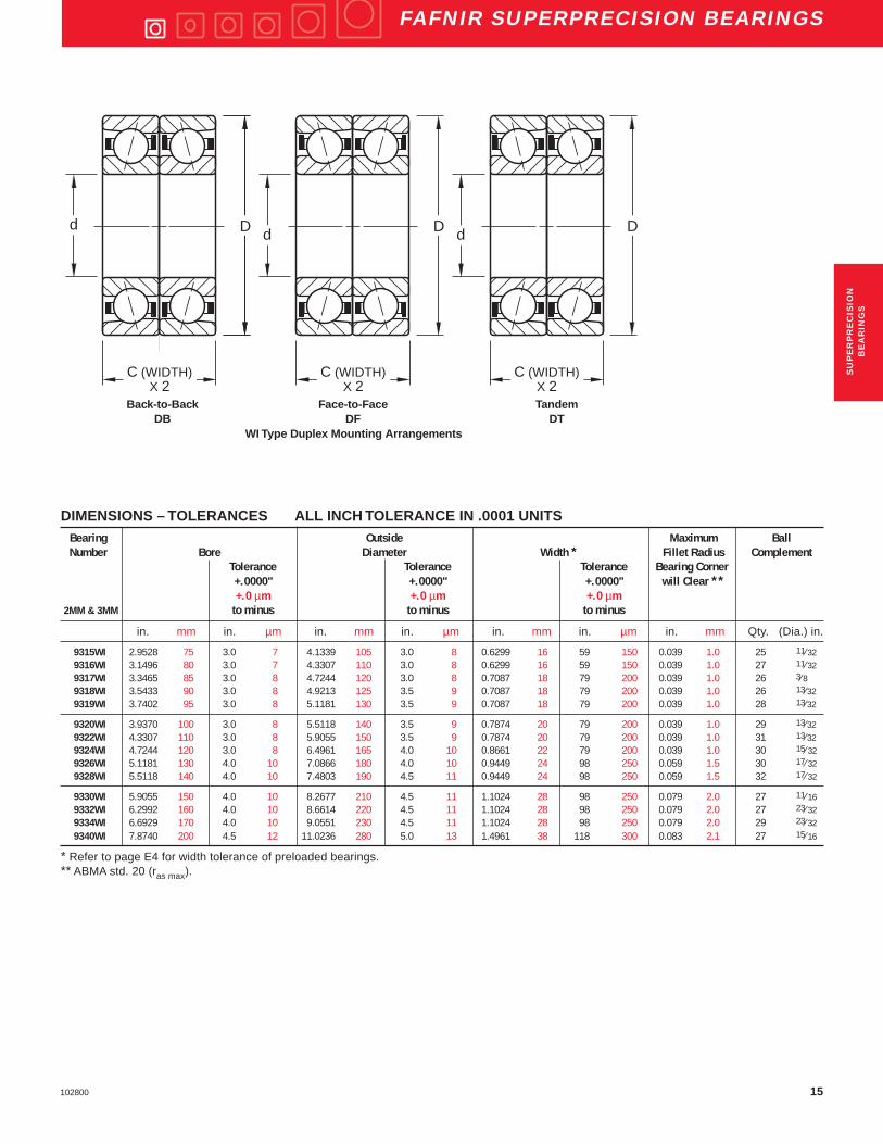
FAFNIR SUPERPRECISION BEARINGS
DIMENSIONS – TOLERANCES ALL INCH TOLERANCE IN .0001 UNITSBearing Outside Maximum BallNumber Bore Diameter Width * Fillet Radius Complement
Tolerance Tolerance Tolerance Bearing Corner+.0000" +.0000" +.0000" will Clear **+.0 µm +.0 µm +.0 µm
2MM & 3MM to minus to minus to minus
in. mm in. µm in. mm in. µm in. mm in. µm in. mm Qty. (Dia.) in.
9300WI 0.3937 10 1.5 4 0.8661 22 2.0 5 0.2362 6 16 40 0.012 0.3 12 1⁄89301WI 0.4724 12 1.5 4 0.9449 24 2.0 5 0.2362 6 31 80 0.012 0.3 13 1⁄89302WI 0.5906 15 1.5 4 1.1024 28 2.0 5 0.2756 7 31 80 0.012 0.3 13 9⁄649303WI 0.6693 17 1.5 4 1.1811 30 2.0 5 0.2756 7 31 80 0.012 0.3 14 9⁄649304WI 0.7874 20 2.0 5 1.4567 37 2.5 6 0.3543 9 47 120 0.012 0.3 14 3⁄16
9305WI 0.9843 25 2.0 5 1.6535 42 2.5 6 0.3543 9 47 120 0.012 0.3 17 3⁄169306WI 1.1811 30 2.0 5 1.8504 47 2.5 6 0.3543 9 47 120 0.012 0.3 19 3⁄169307WI 1.3780 35 2.5 6 2.1654 55 3.0 7 0.3937 10 47 120 0.024 0.6 19 7⁄329308WI 1.5748 40 2.5 6 2.4409 62 3.0 7 0.4724 12 47 120 0.024 0.6 19 1⁄49309WI 1.7717 45 2.5 6 2.6772 68 3.0 7 0.4724 12 47 120 0.024 0.6 21 1⁄4
9310WI 1.9685 50 2.5 6 2.8346 72 3.0 7 0.4724 12 47 120 0.024 0.6 23 1⁄49311WI 2.1654 55 3.0 7 3.1496 80 3.0 7 0.5118 13 59 150 0.039 1.0 23 9⁄ 329312WI 2.3622 60 3.0 7 3.3465 85 3.0 8 0.5118 13 59 150 0.039 1.0 25 9⁄ 329313WI 2.5591 65 3.0 7 3.5433 90 3.0 8 0.5118 13 59 150 0.039 1.0 27 9⁄ 32
9314WI 2.7559 70 3.0 7 3.9370 100 3.0 8 0.6299 16 59 150 0.039 1.0 24 11⁄ 32
* Refer to page E4 for width tolerance of preloaded bearings.** ABMA std. 20 (ras max).
Ultra-Light2MM9300WI &3MM9300WI Series
TO ORDER: Specify bearing number with prefix 2MM for 15 ° contactangle and 3MM for 25 ° contact angle.
Example 2MM9300WI CR
Dd
C
C
Superprecision MM:Superprecision bearings are manufactured to a ABEC-7(ISO P4) tolerance class.
WI Construction:This design incorporates a low shoulder on the non-thrustside of the outer rings. The maximum complement of ballsis separated by a one-piece cage which is piloted againstthe ground thrust shoulder land of the outer ring.
15102800
FAFNIR SUPERPRECISION BEARINGS
SU
PE
RP
RE
CIS
ION
BE
AR
ING
S
DIMENSIONS – TOLERANCES ALL INCH TOLERANCE IN .0001 UNITSBearing Outside Maximum BallNumber Bore Diameter Width * Fillet Radius Complement
Tolerance Tolerance Tolerance Bearing Corner+.0000" +.0000" +.0000" will Clear **+.0 µm +.0 µm +.0 µm
2MM & 3MM to minus to minus to minus
in. mm in. µm in. mm in. µm in. mm in. µm in. mm Qty. (Dia.) in.
9315WI 2.9528 75 3.0 7 4.1339 105 3.0 8 0.6299 16 59 150 0.039 1.0 25 11⁄329316WI 3.1496 80 3.0 7 4.3307 110 3.0 8 0.6299 16 59 150 0.039 1.0 27 11⁄329317WI 3.3465 85 3.0 8 4.7244 120 3.0 8 0.7087 18 79 200 0.039 1.0 26 3⁄89318WI 3.5433 90 3.0 8 4.9213 125 3.5 9 0.7087 18 79 200 0.039 1.0 26 13⁄329319WI 3.7402 95 3.0 8 5.1181 130 3.5 9 0.7087 18 79 200 0.039 1.0 28 13⁄32
9320WI 3.9370 100 3.0 8 5.5118 140 3.5 9 0.7874 20 79 200 0.039 1.0 29 13⁄329322WI 4.3307 110 3.0 8 5.9055 150 3.5 9 0.7874 20 79 200 0.039 1.0 31 13⁄329324WI 4.7244 120 3.0 8 6.4961 165 4.0 10 0.8661 22 79 200 0.039 1.0 30 15⁄ 329326WI 5.1181 130 4.0 10 7.0866 180 4.0 10 0.9449 24 98 250 0.059 1.5 30 17⁄ 329328WI 5.5118 140 4.0 10 7.4803 190 4.5 11 0.9449 24 98 250 0.059 1.5 32 17⁄ 32
9330WI 5.9055 150 4.0 10 8.2677 210 4.5 11 1.1024 28 98 250 0.079 2.0 27 11⁄ 169332WI 6.2992 160 4.0 10 8.6614 220 4.5 11 1.1024 28 98 250 0.079 2.0 27 23⁄ 329334WI 6.6929 170 4.0 10 9.0551 230 4.5 11 1.1024 28 98 250 0.079 2.0 29 23⁄ 32
9340WI 7.8740 200 4.5 12 11.0236 280 5.0 13 1.4961 38 118 300 0.083 2.1 27 15⁄ 16
* Refer to page E4 for width tolerance of preloaded bearings.** ABMA std. 20 (ras max).
C (WIDTH) X 2
d DD d D d D
C (WIDTH) X 2
C (WIDTH) X 2
Back-to-Back Face-to-Face TandemDB DF DT
WI Type Duplex Mounting Arrangements

16 102800
FAFNIR SUPERPRECISION BEARINGS
PHYSICAL CHARACTERISTICS – LOAD RATINGSBearing Weight Static Extended Permis- Preload LevelsNumber Per Bearing Load Rating Dynamic sible
Load Ratings SpeedCo Ce Ng * Extralight (1) Light Medium Heavy
(DUX) (DUL) (DUM) (DUH)
lbs kg lbs N lbs N RPM lbs N lbs N lbs N lbs N
2MM9300WI 0.02 0.010 285 1,300 735 3,300 77,500 — — 3 15 6 25 12 552MM9301WI 0.03 0.011 320 1,400 765 3,400 67,200 — — 3 15 6 25 12 552MM9302WI 0.04 0.016 415 1,800 950 4,200 55,600 — — 5 20 10 45 20 902MM9303WI 0.04 0.018 490 2,200 1,040 4,600 50,100 — — 5 20 15 65 30 1302MM9304WI 0.08 0.037 780 3,500 1,700 7,600 42,100 — — 10 45 20 90 35 160
2MM9305WI 0.10 0.043 1,000 4,400 1,900 8,500 34,800 — — 10 45 25 110 40 1802MM9306WI 0.11 0.050 1,140 5,100 2,000 8,900 29,700 — — 10 45 25 110 40 1802MM9307WI 0.17 0.077 1,560 6,900 2,600 11,600 25,400 — — 10 45 25 110 55 2402MM9308WI 0.25 0.112 2,040 9,100 3,350 14,900 22,400 5 30 15 65 35 160 70 3102MM9309WI 0.29 0.133 2,280 10,100 3,450 15,300 20,000 10 30 20 90 40 180 80 360
2MM9310WI 0.30 0.135 2,550 11,300 3,650 16,200 18,300 10 40 20 90 45 200 90 4002MM9311WI 0.41 0.187 3,200 14,200 4,550 20,200 16,600 10 40 25 110 55 240 110 4902MM9312WI 0.44 0.200 3,450 15,300 4,750 21,100 15,300 10 40 25 110 55 240 115 5102MM9313WI 0.47 0.215 3,750 16,700 4,900 21,800 14,200 15 70 30 130 60 270 120 5302MM9314WI 0.76 0.344 5,000 22,200 6,700 29,800 13,100 15 70 40 180 80 360 160 710
2MM9315WI 0.80 0.363 5,200 23,100 6,800 30,200 12,300 20 90 40 180 85 380 170 7602MM9316WI 0.85 0.385 5,600 24,900 7,100 31,600 11,600 20 90 45 200 90 400 180 8002MM9317WI 1.23 0.556 6,550 29,100 8,150 36,300 10,800 25 110 60 270 120 530 240 10702MM9318WI 1.26 0.573 7,650 34,000 9,500 42,300 10,300 25 110 60 270 120 530 240 10702MM9319WI 1.33 0.601 8,150 36,300 9,800 43,600 9,800 30 130 65 290 130 580 260 1160
2MM9320WI 1.87 0.846 8,300 36,900 9,800 43,600 9,100 30 130 80 360 160 710 330 14702MM9322WI 2.02 0.918 8,800 39,100 10,200 45,400 8,400 40 180 90 400 180 800 360 16002MM9324WI 2.74 1.243 11,600 51,600 12,900 57,400 7,700 45 200 110 490 220 980 440 19602MM9326WI 3.63 1.648 15,000 66,700 16,300 72,500 7,100 50 220 140 620 275 1220 550 24502MM9328WI 3.85 1.746 15,600 69,400 17,000 75,600 6,600 60 270 140 620 280 1250 575 2560
2MM9330WI 5.75 2.609 22,000 97,400 25,000 111,200 6,200 65 290 190 850 380 1690 775 34502MM9332WI 6.06 2.749 32,200 143,100 29,000 128,900 5,800 110 489 220 980 445 1980 890 39602MM9334WI 6.34 2.875 26,000 115,600 28,000 124,500 5,500 80 360 230 1020 460 2050 900 40002MM9340WI 13.87 6.291 54,700 243,300 47,100 209,500 4,600 175 778 350 1560 700 3110 1400 6230
* Limits shown for grease lubricated, single bearing, spring preloaded.(1) Call for availability.
Ultra-Light2MM9300WI Series
RADIAL LOAD RATING AT 33 1⁄3 RPMBased on 1500 hours L 10 Life and Permissible Speed

17102800
FAFNIR SUPERPRECISION BEARINGS
FREQUENCY COEFFICIENTSBearing FTF BSF BPFO BPFI FTFNumber
Fundamental Train Ball Spin Ball Pass Frequency Ball Pass Frequency Fundamental TrainFrequency Frequency Outer Inner Frequency
(Inner Rotation) (Outer Rotation)
2MM9300WI 0.4054 2.4294 4.8649 7.1351 0.59462MM9301WI 0.4159 2.7546 5.4070 7.5930 0.58412MM9302WI 0.4204 2.9335 5.4650 7.5350 0.57962MM9303WI 0.4272 3.2198 6.4074 8.5926 0.57282MM9304WI 0.4194 2.9144 5.8719 8.1281 0.5806
2MM9305WI 0.4314 3.4509 7.3346 9.6654 0.56862MM9306WI 0.4404 3.9846 8.3667 10.6333 0.55962MM9307WI 0.4405 3.9924 8.3695 10.6305 0.55952MM9308WI 0.4399 3.9578 8.3586 10.6414 0.56012MM9309WI 0.4458 4.3966 9.3612 11.6388 0.5542
2MM9310WI 0.4498 4.7547 10.3448 12.6552 0.55022MM9311WI 0.4490 4.6752 10.3262 12.6738 0.55102MM9312WI 0.4525 5.0286 11.3121 13.6879 0.54752MM9313WI 0.4556 5.3816 12.2999 14.7001 0.54442MM9314WI 0.4504 4.8196 10.8092 13.1908 0.5496
2MM9315WI 0.4531 5.1086 11.3285 13.6715 0.54692MM9316WI 0.4556 5.3974 12.3014 14.6986 0.54442MM9317WI 0.4557 5.3371 11.8322 14.1678 0.54492MM9318WI 0.4537 5.1643 11.7957 14.2043 0.54632MM9319WI 0.4557 5.4085 12.7607 15.2393 0.5443
2MM9320WI 0.4585 5.7746 13.2966 15.7034 0.54152MM9322WI 0.4617 6.2622 14.3126 16.6874 0.53832MM9324WI 0.4596 5.9438 13.7888 16.2112 0.54042MM9326WI 0.4580 5.7028 13.7392 16.2608 0.54202MM9328WI 0.4605 6.0759 14.7367 17.2633 0.5395
2MM9330WI 0.4531 5.1086 12.2348 14.7652 0.54692MM9332WI 0.4536 5.1589 12.2480 14.7520 0.54642MM9334WI 0.4559 5.4349 13.2209 15.7791 0.54412MM9340WI 0.4521 4.9931 12.2062 14.7938 0.5479
Ultra-Light2MM9300WI Series
SU
PE
RP
RE
CIS
ION
BE
AR
ING
S
Superprecision Bearings
FTF Fundamental Train Frequency: The frequency atwhich the retainer will operate.
BSF Ball Spin Frequency: The frequency at which asingle defect on a rolling element will be detected.
BPFO Ball Pass Frequency Outer: The frequency atwhich a single defect in the outer race will bedetected.
BPFI Ball Pass Frequency Inner: The frequency atwhich a single defect in the inner race will bedetected.

18 102800
FAFNIR SUPERPRECISION BEARINGS
PHYSICAL CHARACTERISTICS – LOAD RATINGSBearing Weight Static Extended Permis- Preload LevelsNumber Per Bearing Load Rating Dynamic sible
Load Ratings SpeedCo Ce Ng * Extralight Light Medium Heavy
(DUX) (DUL) (DUM) (DUH)
lbs kg lbs N lbs N RPM lbs N lbs N lbs N lbs N
3MM9300WI 0.02 0.010 360 1,580 760 3,380 69,800 — — 5 20 10 45 20 903MM9302WI 0.04 0.016 510 2,280 980 4,360 50,000 — — 10 45 20 90 35 1603MM9303WI 0.04 0.018 600 2,680 1,070 4,740 45,100 — — 10 45 30 130 55 2403MM9305WI 0.10 0.043 1,230 5,500 1,930 8,600 31,300 — — 15 65 40 180 70 310
3MM9306WI 0.11 0.050 1,080 4,800 1,900 8,500 26,700 — — 15 70 40 180 70 3103MM9307WI 0.17 0.077 1,460 6,500 2,500 11,100 22,900 — — 20 90 55 240 95 4203MM9308WI 0.25 0.112 1,930 8,600 3,150 14,000 20,200 — — 30 130 70 310 125 5603MM9309WI 0.29 0.133 2,160 9,600 3,350 14,900 18,000 — — 35 160 80 360 150 670
3MM9310WI 0.30 0.135 2,400 10,700 3,450 15,300 16,500 — — 35 160 90 400 150 6703MM9311WI 0.41 0.187 3,000 13,300 4,300 19,100 14,900 — — 45 200 110 490 190 8503MM9312WI 0.44 0.200 3,250 14,500 4,500 20,000 13,800 — — 45 200 115 510 200 8903MM9313WI 0.47 0.214 3,550 15,800 4,650 20,700 12,800 — — 50 220 120 530 240 10703MM9314WI 0.76 0.344 4,750 21,100 6,300 28,000 11,800 — — 65 290 160 710 290 1290
3MM9315WI 0.80 0.363 4,900 21,800 6,400 28,500 11,100 — — 70 310 170 760 300 13303MM9316WI 0.85 0.385 5,200 23,100 6,700 29,800 10,400 — — 75 330 180 800 310 13803MM9317WI 1.22 0.555 6,000 26,700 7,650 34,000 9,700 — — 100 440 240 1070 420 18703MM9318WI 1.26 0.572 7,100 31,600 8,800 39,100 9,300 — — 90 400 210 930 375 16703MM9319WI 1.32 0.601 7,650 34,000 9,300 41,400 8,800 — — 105 470 260 1160 450 2000
3MM9320WI 1.86 0.846 7,800 34,700 9,300 41,400 8,200 — — 135 600 330 1470 575 25603MM9322WI 2.02 0.917 8,300 36,900 9,500 42,300 7,600 — — 150 670 360 1600 625 27803MM9324WI 2.74 1.242 10,800 48,000 12,200 54,300 6,900 — — 180 800 440 1960 775 34503MM9326WI 3.63 1.647 14,000 62,300 15,600 69,400 6,400 — — 230 1020 550 2450 975 43403MM9328WI 3.85 1.744 14,600 64,900 16,000 71,200 5,900 — — 240 1070 575 2560 1000 4450
3MM9330WI 5.75 2.607 21,200 94,300 23,600 105,000 5,600 — — 325 1450 775 3450 1350 60003MM9334WI 6.33 2.871 24,500 109,000 26,000 115,600 5,000 — — — — — — — —3MM9340WI 13.87 6.291 51,400 228,500 44,400 197,500 4,100 — — 700 3110 1400 6230 2800 12460
* Limits shown for a single row, spring preloaded and grease lubricated bearing.
Ultra-Light3MM9300WI Series
RADIAL LOAD RATING AT 33 1⁄3 RPMBased on 1500 hours L 10 Life and Permissible Speed

19102800
FAFNIR SUPERPRECISION BEARINGS
FREQUENCY COEFFICIENTS
Bearing FTF BSF BPFO BPFI FTFNumber Fundamental Train Ball Spin Ball Pass Frequency Ball Pass Frequency Fundamental Train
Frequency Frequency Outer Inner Frequency(Inner Rotation) (Outer Rotation)
3MM9300WI 0.4100 2.4380 4.9204 7.0796 0.59003MM9302WI 0.4248 2.9417 5.5225 7.4775 0.57523MM9303WI 0.4312 3.2273 6.4681 8.5319 0.56883MM9305WI 0.4356 3.4586 7.4044 9.5956 0.5644
3MM9306WI 0.4439 3.9913 8.4346 10.5654 0.55613MM9307WI 0.4440 3.9990 8.4366 10.5634 0.55603MM9308WI 0.4437 3.9648 8.4295 10.5705 0.55633MM9309WI 0.4491 4.4029 9.4320 11.5680 0.5509
3MM9310WI 0.4529 4.7606 10.4166 12.5834 0.54713MM9311WI 0.4521 4.6811 10.3983 12.6017 0.54793MM9312WI 0.4554 5.0340 11.3851 13.6149 0.54463MM9313WI 0.4583 5.3867 12.3736 14.6264 0.54173MM9314WI 0.4535 4.8255 10.8839 13.1161 0.5465
3MM9315WI 0.4561 5.1141 11.4020 13.5980 0.54393MM9316WI 0.4584 5.4026 12.3766 14.6234 0.54163MM9317WI 0.4579 5.3423 11.9047 14.0953 0.54213MM9318WI 0.4565 5.1696 11.8699 14.1301 0.54353MM9319WI 0.4585 5.4136 12.8371 15.1629 0.5415
3MM9320WI 0.4611 5.7794 13.3708 15.6292 0.53893MM9322WI 0.4641 6.2666 14.3858 16.6142 0.53593MM9324WI 0.4622 5.9485 13.8645 16.1355 0.53783MM9326WI 0.4606 5.7077 13.8171 16.1829 0.53943MM9328WI 0.4630 6.0804 14.8147 17.1853 0.5370
3MM9330WI 0.4561 5.1141 12.3141 14.6859 0.54393MM9334WI 0.4586 5.4401 13.3007 15.6993 0.54143MM9340WI 0.4551 4.9987 12.2879 14.7121 0.5449
Ultra-Light3MM9300WI Series
Superprecision Bearings
FTF Fundamental Train Frequency: The frequency atwhich the retainer will operate.
BSF Ball Spin Frequency: The frequency at which asingle defect on a rolling element will be detected.
BPFO Ball Pass Frequency Outer: The frequency atwhich a single defect in the outer race will bedetected.
BPFI Ball Pass Frequency Inner: The frequency atwhich a single defect in the inner race will bedetected.
SU
PE
RP
RE
CIS
ION
BE
AR
ING
S

20 102800
FAFNIR SUPERPRECISION BEARINGS
PERMISSIBLE OPERATING SPEEDS – RPM2MM & 3MM Superprecision Angular Contact Spindle Bearings
GREASE OIL
“DB” Mounting Grease Capacity Kluber Isoflex NBU 15 “DB” Mounting15 Degree (DUL) (DUM) (DUH) 25 % 40 % 15 % 20 % (DUL) (DUM) (DUH)
Contact Angle Light Medium Heavy (grams) (grams) (grams) (grams) Light Medium Heavy
2MM9300WI 62,000 46,500 31,000 0.09 0.15 0.06 0.08 105,400 79,100 52,7002MM9301WI 53,800 40,300 26,900 0.11 0.17 0.07 0.10 91,500 68,500 45,7002MM9302WI 44,500 33,400 22,200 0.17 0.28 0.12 0.15 75,700 56,800 37,7002MM9303WI 40,100 30,100 20,000 0.19 0.30 0.12 0.16 68,200 51,200 34,0002MM9304WI 33,700 25,300 16,800 0.4 0.6 0.25 0.34 57,300 43,000 28,600
2MM9305WI 27,800 20,900 13,900 0.4 0.7 0.29 0.39 47,300 35,500 23,6002MM9306WI 23,800 17,800 11,900 0.5 0.8 0.34 0.45 40,500 30,300 20,2002MM9307WI 20,300 15,200 10,200 0.8 1.2 0.51 0.68 34,500 25,800 17,3002MM9308WI 17,900 13,400 9,000 1.2 1.9 0.80 1.07 30,400 22,800 15,3002MM9309WI 16,000 12,000 8,000 1.3 2.1 0.88 1.18 27,200 20,400 13,600
2MM9310WI 14,600 11,000 7,300 1.4 2.3 0.95 1.27 24,800 18,700 12,4002MM9311WI 13,300 10,000 6,600 1.9 3.0 1.3 1.7 22,600 17,000 11,2002MM9312WI 12,200 9,200 6,100 2.0 3.2 1.4 1.8 20,700 15,600 10,4002MM9313WI 11,400 8,500 5,700 2.1 3.4 1.4 1.9 19,400 14,500 9,7002MM9314WI 10,500 7,900 5,200 3.6 5.7 2.4 3.2 17,900 13,400 8,800
2MM9315WI 9,800 7,400 4,900 3.8 6.1 2.5 3.4 16,700 12,600 8,3002MM9316WI 9,300 7,000 4,600 4.0 6.4 2.7 3.5 15,800 11,900 7,8002MM9317WI 8,600 6,500 4,300 5.3 8.6 3.6 4.8 14,600 11,100 7,3002MM9318WI 8,200 6,200 4,100 5.9 9.4 3.9 5.2 13,900 10,500 7,0002MM9319WI 7,800 5,900 3,900 6.1 9.7 4.1 5.4 13,300 10,000 6,600
2MM9320WI 7,300 5,500 3,600 7.5 12.0 5.0 6.7 12,400 9,400 6,1002MM9322WI 6,700 5,000 3,400 8.1 13.0 5.4 7.3 11,400 8,500 5,8002MM9324WI 6,200 4,600 3,100 11.1 17.8 7.4 9.9 10,500 7,800 5,3002MM9326WI 5,700 4,300 2,800 14.6 23.3 9.7 13.0 9,700 7,300 4,8002MM9328WI 5,300 4,000 2,600 15.5 24.8 10.4 13.8 9,000 6,800 4,400
2MM9330WI 5,000 3,700 2,500 24.8 39.7 16.6 22.1 8,500 6,300 4,3002MM9332WI 4,600 3,500 2,300 26.2 41.9 17.5 23.3 7,900 5,900 3,9002MM9334WI 4,400 3,300 2,200 28.2 45.2 18.9 25.1 7,500 5,600 3,7002MM9340WI 3,700 2,800 1,800 56.8 90.9 37.9 50.6 6,300 4,700 3,100
Notes: For 3MM (25 Degree Contact Angle) Spindle Bearings, use 90% of the Permissible Operating Speeds above.* For 2MMC and 3MMC Spindle Bearings, use 120% of the Permissible Operating Speeds.For other bearing configurations beside a back-to-back mounted duplex set, please refer to page E36 to calculate thepermissible operating speed (Sp.).
Ultra-Light9300WI Series
21102800
FAFNIR SUPERPRECISION BEARINGS
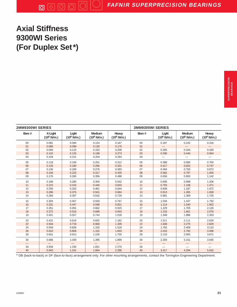
2MM9300WI SERIES 3MM9300WI SERIES
Bore # X-Light Light Medium Heavy Bore # Light Medium Heavy(106 lb/in.) (106 lb/in.) (106 lb/in.) (106 lb/in.) (106 lb/in.) (106 lb/in.) (106 lb/in.)
00 0.081 0.094 0.124 0.167 00 0.187 0.242 0.31601 0.085 0.099 0.130 0.175 01 — — —02 0.094 0.115 0.153 0.209 02 0.265 0.344 0.43003 0.102 0.125 0.198 0.273 03 0.290 0.440 0.56404 0.104 0.151 0.204 0.264 04 — — —
05 0.118 0.169 0.251 0.312 05 0.388 0.560 0.70006 0.126 0.180 0.266 0.331 06 0.417 0.602 0.74707 0.145 0.189 0.276 0.393 07 0.484 0.705 0.87208 0.156 0.223 0.317 0.435 08 0.582 0.797 1.00009 0.176 0.265 0.356 0.488 09 0.656 0.893 1.142
10 0.196 0.280 0.394 0.542 10 0.695 0.998 1.20611 0.222 0.316 0.440 0.603 11 0.793 1.108 1.37112 0.250 0.333 0.461 0.644 12 0.839 1.187 1.47213 0.286 0.375 0.501 0.684 13 0.913 1.265 1.65814 0.284 0.397 0.532 0.729 14 0.981 1.369 1.725
15 0.304 0.407 0.559 0.767 15 1.034 1.437 1.79216 0.331 0.447 0.598 0.821 16 1.114 1.540 1.90217 0.351 0.491 0.662 0.915 17 1.229 1.705 2.12618 0.372 0.516 0.689 0.943 18 1.216 1.661 2.07619 0.401 0.557 0.744 1.018 19 1.348 1.886 2.333
20 0.431 0.619 0.832 1.162 20 1.511 2.111 2.62922 0.504 0.719 0.969 1.339 22 1.638 2.275 2.82924 0.559 0.826 1.102 1.518 24 1.782 2.409 3.11026 0.610 0.858 1.152 1.603 26 2.016 2.792 3.49628 0.601 0.913 1.226 1.700 28 2.133 2.955 3.671
30 0.686 1.039 1.395 1.899 30 2.293 3.151 3.935— — — — — — — — —34 0.934 1.230 1.651 2.270 34 — — —40 0.943 1.241 1.664 2.286 40 3.317 4.294 5.632
* DB (back-to-back) or DF (face-to-face) arrangement only; For other mounting arrangements, contact the Torrington Engineering Department.
Axial Stiffness9300WI Series(For Duplex Set*)
SU
PE
RP
RE
CIS
ION
BE
AR
ING
S
22 102800
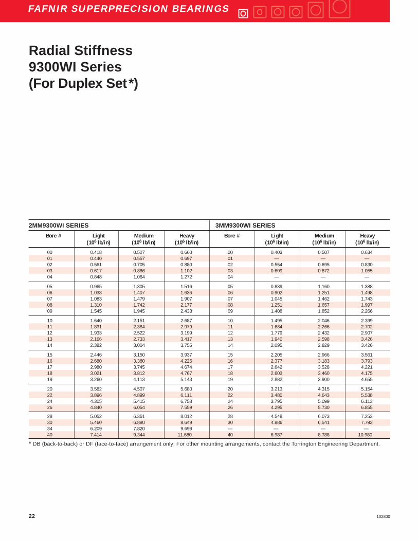
FAFNIR SUPERPRECISION BEARINGS
2MM9300WI SERIES 3MM9300WI SERIES
Bore # Light Medium Heavy Bore # Light Medium Heavy(106 lb/in) (106 lb/in) (106 lb/in) (106 lb/in) (106 lb/in) (106 lb/in)
00 0.418 0.527 0.660 00 0.403 0.507 0.63401 0.440 0.557 0.697 01 — — —02 0.561 0.705 0.880 02 0.554 0.695 0.83003 0.617 0.886 1.102 03 0.609 0.872 1.05504 0.848 1.064 1.272 04 — — —
05 0.965 1.305 1.516 05 0.839 1.160 1.38806 1.038 1.407 1.636 06 0.902 1.251 1.49807 1.083 1.479 1.907 07 1.045 1.462 1.74308 1.310 1.742 2.177 08 1.251 1.657 1.99709 1.545 1.945 2.433 09 1.408 1.852 2.266
10 1.640 2.151 2.687 10 1.495 2.046 2.39911 1.831 2.384 2.979 11 1.684 2.266 2.70212 1.933 2.522 3.199 12 1.779 2.432 2.90713 2.166 2.733 3.417 13 1.940 2.598 3.42614 2.382 3.004 3.755 14 2.095 2.829 3.426
15 2.446 3.150 3.937 15 2.205 2.966 3.56116 2.680 3.380 4.225 16 2.377 3.183 3.79317 2.980 3.745 4.674 17 2.642 3.528 4.22118 3.021 3.812 4.767 18 2.603 3.460 4.17519 3.260 4.113 5.143 19 2.882 3.900 4.655
20 3.582 4.507 5.680 20 3.213 4.315 5.15422 3.896 4.899 6.111 22 3.480 4.643 5.53824 4.305 5.415 6.758 24 3.795 5.099 6.11326 4.840 6.054 7.559 26 4.295 5.730 6.855
28 5.052 6.361 8.012 28 4.548 6.073 7.25330 5.460 6.880 8.649 30 4.886 6.541 7.79334 6.209 7.820 9.699 — — — —40 7.414 9.344 11.680 40 6.987 8.788 10.980
* DB (back-to-back) or DF (face-to-face) arrangement only; For other mounting arrangements, contact the Torrington Engineering Department.
Radial Stiffness9300WI Series(For Duplex Set*)

23102800
FAFNIR SUPERPRECISION BEARINGS
2MM9300WI Series 3MM9300WI Series
Bore # X-Light Light to Medium Bore # Light Mediumto Light Medium to Heavy Medium Heavy
00 0.00005 0.00011 0.00016 00 0.00010 0.0001501 0.00004 0.00010 0.00016 01 — —02 0.00008 0.00015 0.00022 02 0.00013 0.0001603 0.00007 0.00025 0.00025 03 0.00022 0.0002004 0.00019 0.00023 0.00026 04 — —
05 0.00017 0.00029 0.00021 05 0.00021 0.0001906 0.00016 0.00027 0.00020 06 0.00020 0.0001807 0.00012 0.00026 0.00036 07 0.00023 0.0002008 0.00019 0.00030 0.00037 08 0.00023 0.0002409 0.00023 0.00026 0.00038 09 0.00023 0.00027
10 0.00020 0.00030 0.00038 10 0.00026 0.0002211 0.00022 0.00032 0.00042 11 0.00027 0.0002612 0.00018 0.00030 0.00043 12 0.00027 0.0002613 0.00018 0.00027 0.00041 13 0.00026 0.0003314 0.00027 0.00034 0.00051 14 0.00032 0.00034
15 0.00024 0.00037 0.00051 15 0.00032 0.0003216 0.00025 0.00034 0.00051 16 0.00031 0.0003017 0.00032 0.00042 0.00061 17 0.00038 0.0003818 0.00031 0.00040 0.00059 18 0.00033 0.0003519 0.00031 0.00040 0.00059 19 0.00038 0.00036
20 0.00036 0.00044 0.00068 20 0.00043 0.0004122 0.00036 0.00045 0.00067 22 0.00043 0.0004124 0.00042 0.00052 0.00076 24 0.00048 0.0004826 0.00051 0.00056 0.00084 26 0.00053 0.0005428 0.00044 0.00056 0.00086 28 — —
30 0.00066 0.00071 0.00108 30 — —34 0.00069 0.00076 0.00107 34 — —40 0.00064 0.00096 0.00142 40 0.00074 0.00113
* DB (back-to-back) or DF (face-to-face) arrangement only; For other mounting arrangements, contact the Torrington Engineering Department.
Spacer Offsets9300WI Series(For Duplex Set*)
SU
PE
RP
RE
CIS
ION
BE
AR
ING
S
24 102800
FAFNIR SUPERPRECISION BEARINGS
DIMENSIONS – TOLERANCESAll Inch tolerance in .0001 units
Bearing Outside Maximum BallNumber Bore Diameter Width * Fillet Radius Complement
Tolerance Tolerance Tolerance Bearing Corner Bearing Corner
+.0000" +.0000" +.0000" will Clear **+.0mm +.0mm +.0mm
to minus to minus to minus
2MMV &3MMV in. mm in. µm in. mm in. µm in. mm in. µm in. mm Qty. (Dia.) in.
99101WN 0.4724 12 1.5 4 1.1024 28 2.0 5 0.3150 8 31 80 0.012 0.3 9 3⁄1699102WN 0.5906 15 1.5 4 1.2598 32 2.5 6 0.3543 9 31 80 0.012 0.3 11 3⁄ 1699103WN 0.6693 17 1.5 4 1.3780 35 2.5 6 0.3937 10 31 80 0.012 0.3 13 3⁄ 1699104WN 0.7874 20 2.0 5 1.6535 42 2.5 6 0.4724 12 47 120 0.024 0.6 11 1⁄499105WN 0.9843 25 2.0 5 1.8504 47 2.5 6 0.4724 12 47 120 0.024 0.6 13 1⁄4
99106WN 1.1811 30 2.0 5 2.1654 55 3.0 7 0.5118 13 47 120 0.039 1.0 16 1⁄499107WN 1.3780 35 2.5 6 2.4409 62 3.0 7 0.5512 14 47 120 0.039 1.0 21 7⁄ 3299108WN 1.5748 40 2.5 6 2.6772 68 3.0 7 0.5906 15 47 120 0.039 1.0 24 7⁄ 3299109WN 1.7717 45 2.5 6 2.9528 75 3.0 7 0.6299 16 47 120 0.039 1.0 23 1⁄499110WN 1.9685 50 2.5 6 3.1496 80 3.0 7 0.6299 16 47 120 0.039 1.0 25 1⁄4
99111WN 2.1654 55 3.0 7 3.5433 90 3.0 8 0.7087 18 59 150 0.039 1.0 25 9⁄ 3299112WN 2.3622 60 3.0 7 3.7402 95 3.0 8 0.7087 18 59 150 0.039 1.0 26 9⁄ 3299113WN 2.5591 65 3.0 7 3.9370 100 3.0 8 0.7087 18 59 150 0.039 1.0 28 9⁄ 3299114WN 2.7559 70 3.0 7 4.3307 110 3.0 8 0.7874 20 59 150 0.039 1.0 28 5⁄ 1699115WN 2.9528 75 3.0 7 4.5276 115 3.0 8 0.7874 20 59 150 0.039 1.0 30 5⁄ 16
* Refer to page E4 for width tolerance of preloaded bearings.** ABMA std. 20 (ras max).
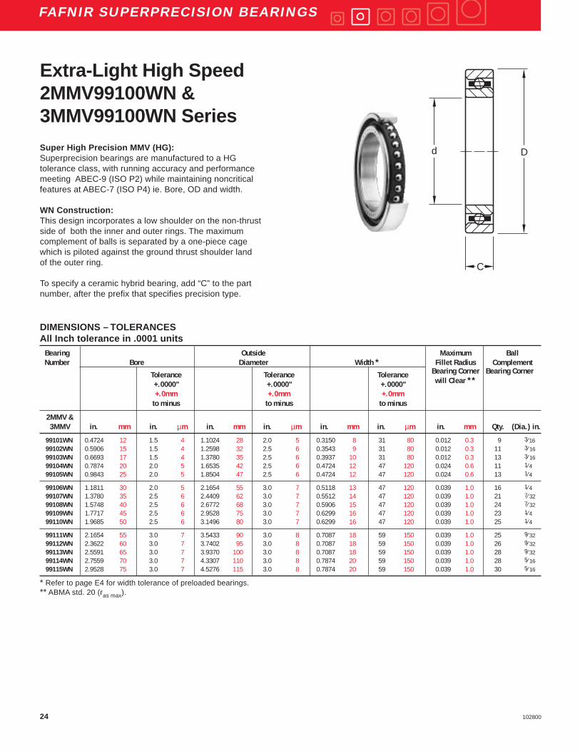
Extra-Light High Speed2MMV99100WN &3MMV99100WN Series
Dd
C
Super High Precision MMV (HG):Superprecision bearings are manufactured to a HGtolerance class, with running accuracy and performancemeeting ABEC-9 (ISO P2) while maintaining noncriticalfeatures at ABEC-7 (ISO P4) ie. Bore, OD and width.
WN Construction:This design incorporates a low shoulder on the non-thrustside of both the inner and outer rings. The maximumcomplement of balls is separated by a one-piece cagewhich is piloted against the ground thrust shoulder landof the outer ring.
To specify a ceramic hybrid bearing, add “C” to the partnumber, after the prefix that specifies precision type.

25102800
FAFNIR SUPERPRECISION BEARINGS
DIMENSIONS – TOLERANCESAll Inch tolerance in .0001 units
Bearing Outside Maximum BallNumber Bore Diameter Width * Fillet Radius Complement
Tolerance Tolerance Tolerance Bearing Corner
+.0000" +.0000" +.0000" will Clear **
+.0mm +.0mm +.0mmto minus to minus to minus
2MMV &3MMV in. mm in. µm in. mm in. µm in. mm in. µm in. mm Qty. (Dia.) in.
99116WN 3.1496 80 3.0 7 4.9213 125 3.5 9 0.8661 22 59 150 0.039 1.0 29 11⁄ 3299117WN 3.3465 85 3.0 8 5.1181 130 3.5 9 0.8661 22 79 200 0.039 1.0 31 11⁄ 3299118WN 3.5433 90 3.0 8 5.5118 140 3.5 9 0.9449 24 79 200 0.059 1.5 28 13⁄ 3299119WN 3.7402 95 3.0 8 5.7087 145 3.5 9 0.9449 24 79 200 0.059 1.5 29 13⁄ 3299120WN 3.9370 100 3.0 8 5.9055 150 3.5 9 0.9449 24 79 200 0.059 1.5 31 13⁄ 32
99121WN 4.1339 105 3.0 8 6.2992 160 4.0 10 1.0236 26 79 200 0.079 2.0 30 7⁄ 1699122WN 4.3307 110 3.0 8 6.6929 170 4.0 10 1.1024 28 79 200 0.079 2.0 30 15⁄ 3299124WN 4.7244 120 3.0 8 7.0866 180 4.0 10 1.1024 28 79 200 0.079 2.0 32 15⁄ 3299126WN 5.1181 130 4.0 10 7.8740 200 4.5 11 1.2992 33 98 250 0.079 2.0 32 17⁄ 3299128WN 5.5118 140 4.0 10 8.2677 210 4.5 11 1.2992 33 98 250 0.079 2.0 34 17⁄ 32
99130WN 5.9055 150 4.0 10 8.8583 225 4.5 11 1.3780 35 98 250 0.079 2.0 34 19⁄ 32
* Refer to page E4 for width tolerance of preloaded bearings.** ABMA std. 20 (ras max).
Dd
C (WIDTH)X 2
Dd
C (WIDTH)X 2
Dd
C (WIDTH)X 2
Back-to-Back Face-to-Face TandemDB DF DT
WN Type Duplex Mounting Arrangement
SU
PE
RP
RE
CIS
ION
BE
AR
ING
S

26 102800
FAFNIR SUPERPRECISION BEARINGS
PHYSICAL CHARACTERISTICS – LOAD RATINGSBearing Weight Static Extended Permis- Preload Levels **Number Per Bearing Load Rating Dynamic sible
Load Ratings SpeedCo Ce Ng * Extralight Light Medium Heavy
(DUX) (DUL) (DUM) (DUH)
lbs kg lbs N lbs N RPM lbs N lbs N lbs N lbs N
2MMV99101WN 0.04 0.019 380 1,700 1,160 5,200 75,800 — — 5 20 10 40 20 902MMV99102WN 0.06 0.028 490 2,200 1,320 5,900 64,300 — — 5 20 10 40 20 902MMV99103WN 0.08 0.038 600 2,700 1,500 6,700 56,900 — — 5 20 10 40 20 902MMV99104WN 0.14 0.064 1,040 4,600 2,450 10,900 43,800 5 20 10 40 20 90 40 1802MMV99105WN 0.16 0.074 1,290 5,700 2,700 12,000 36,500 5 20 15 70 30 130 60 270
2MMV99106WN 0.25 0.116 1,660 7,400 3,050 13,600 29,500 5 20 15 70 30 130 60 2702MMV99107WN 0.37 0.167 1,730 7,700 2,800 12,500 25,300 10 40 20 90 40 180 80 3602MMV99108WN 0.46 0.207 2,040 9,100 3,000 13,300 22,000 15 70 25 110 50 220 100 4402MMV99109WN 0.57 0.259 2,550 11,300 3,650 16,200 20,200 15 70 30 130 60 270 120 5302MMV99110WN 0.62 0.281 2,750 12,200 3,800 16,900 18,500 15 70 30 130 60 270 120 530
2MMV99111WN 0.92 0.417 3,450 15,300 4,750 21,100 16,600 20 90 40 180 80 360 160 7102MMV99112WN 0.98 0.445 3,650 16,200 4,800 21,400 15,400 20 90 40 180 80 360 160 7102MMV99113WN 1.05 0.474 3,900 17,300 5,000 22,200 14,400 25 110 50 220 100 440 200 8902MMV99114WN 1.47 0.665 4,800 21,400 6,000 26,700 13,200 25 110 50 220 100 440 200 8902MMV99115WN 1.54 0.699 5,100 22,700 6,200 27,600 12,300 30 130 60 270 120 530 240 1070
2MMV99116WN 2.08 0.944 6,000 26,700 7,350 32,700 11,600 35 160 70 310 140 620 280 12502MMV99117WN 2.18 0.991 6,400 28,500 7,500 33,400 11,000 40 180 80 360 160 710 320 14202MMV99118WN 2.79 1.266 8,150 36,300 9,300 41,400 10,400 45 200 90 400 180 800 360 16002MMV99119WN 2.87 1.303 8,300 36,900 9,300 41,400 9,900 45 200 90 400 180 800 360 16002MMV99120WN 3.03 1.374 9,000 40,000 10,200 45,400 9,400 50 220 100 440 200 890 400 1780
2MMV99121WN 3.81 1.729 10,000 44,500 11,400 50,700 8,900 55 240 110 490 220 980 440 19602MMV99122WN 4.82 2.188 11,400 50,700 12,900 57,400 8,500 60 270 120 530 240 1070 480 21402MMV99124WN 5.17 2.343 12,200 54,300 13,400 59,600 7,900 70 310 140 620 280 1250 560 24902MMV99126WN 7.85 3.563 15,600 69,400 17,000 75,600 7,100 90 400 180 800 360 1600 720 32002MMV99128WN 8.32 3.776 16,600 73,800 17,300 77,000 6,600 95 420 190 850 380 1690 760 3380
2MMV99130WN 9.94 4.509 20,000 89,000 20,800 92,500 6,200 100 440 200 890 400 1780 800 3560
* Limits shown for a single row, spring preloaded and grease lubricated bearing.** All ceramic hybrid bearing preloads are equivalent to the table above.
Extra-Light High Speed2MMV99100WN Series
RADIAL LOAD RATING AT 33 1⁄ 3 RPMBased on 1500 hours L 10 Life and Permissible Speed

27102800
FAFNIR SUPERPRECISION BEARINGS
FREQUENCY COEFFICIENTS
Bearing FTF BSF BPFO BPFI FTFNumber
Fundamental Train Ball Spin Ball Pass Frequency Ball Pass Frequency Fundamental TrainFrequency Frequency Outer Inner Frequency
(Inner Rotation) (Outer Rotation)
2MMV99101WN 0.3887 2.0593 3.4985 5.5015 0.61132MMV99102WN 0.4023 2.3729 4.4250 6.5750 0.59772MMV99103WN 0.4115 2.6389 5.3494 7.6506 0.58852MMV99104WN 0.4011 2.3455 4.4120 6.5880 0.59892MMV99105WN 0.4148 2.7523 5.3928 7.6072 0.5852
2MMV99106WN 0.4288 3.3241 6.8615 9.1385 0.57122MMV99107WN 0.4448 4.3111 9.3403 11.6597 0.55522MMV99108WN 0.4512 4.8947 10.8295 13.1705 0.54882MMV99109WN 0.4489 4.6750 10.3246 12.6754 0.55112MMV99110WN 0.4528 5.0724 11.3207 13.6793 0.5472
2MMV99111WN 0.4525 5.0285 11.3121 13.6879 0.54752MMV99112WN 0.4556 5.3815 11.8443 14.1557 0.54442MMV99113WN 0.4582 5.7340 12.8308 15.1692 0.54182MMV99114WN 0.4575 5.6283 12.8104 15.1896 0.54252MMV99115WN 0.4602 6.0120 13.8057 16.1943 0.5398
2MMV99116WN 0.4589 5.8300 13.3085 15.6915 0.54112MMV99117WN 0.4610 6.1310 14.2906 16.7094 0.53902MMV99118WN 0.4568 5.5308 12.7902 15.2098 0.54322MMV99119WN 0.4586 5.7748 13.2992 15.7008 0.54142MMV99120WN 0.4606 6.0708 14.2782 16.7218 0.5394
2MMV99121WN 0.4596 5.9229 13.7892 16.2108 0.54042MMV99122WN 0.4591 5.8399 13.7729 16.2271 0.54092MMV99124WN 0.4618 6.2625 14.7784 17.2216 0.53822MMV99126WN 0.4610 6.1362 14.7512 17.2488 0.53902MMV99128WN 0.4633 6.5243 15.7513 18.2487 0.5367
2MMV99130WN 0.4616 6.2346 15.2336 17.7664 0.5384
Extra-Light High Speed2MMV99100WN SeriesSuperprecision Bearings
FTF Fundamental Train Frequency: The frequency atwhich the retainer will operate.
BSF Ball Spin Frequency: The frequency at which asingle defect on a rolling element will be detected.
BPFO Ball Pass Frequency Outer: The frequency atwhich a single defect in the outer race will bedetected.
BPFI Ball Pass Frequency Inner: The frequency atwhich a single defect in the inner race will bedetected.
SU
PE
RP
RE
CIS
ION
BE
AR
ING
S

28 102800
FAFNIR SUPERPRECISION BEARINGS
PHYSICAL CHARACTERISTICS – LOAD RATINGSBearing Weight Static Extended Permis- Preload Levels **Number Per Bearing Load Rating Dynamic sible
Co Load Ratings SpeedCe Ng * Extralight Light Medium Heavy
(DUX) (DUL) (DUM) (DUH)
lbs kg lbs N lbs N RPM lbs N lbs N lbs N lbs N
3MMV99101WN 0.04 0.019 365 1,600 1,100 4,900 68,200 — — 10 40 20 90 40 1803MMV99102WN 0.06 0.028 465 2,100 1,270 5,600 57,900 — — 10 40 20 90 40 1803MMV99103WN 0.08 0.038 570 2,500 1,400 6,200 51,200 — — 10 40 20 90 40 1803MMV99104WN 0.14 0.064 930 4,100 2,320 10,300 39,400 10 40 20 90 40 180 80 3603MMV99105WN 0.16 0.074 1,220 5,400 2,600 11,600 32,900 15 70 30 130 60 270 120 530
3MMV99106WN 0.25 0.116 1,560 6,900 2,900 12,900 26,600 15 70 30 130 60 270 120 5303MMV99107WN 0.37 0.167 1,660 7,400 2,600 11,600 22,800 20 90 40 180 80 360 160 7103MMV99108WN 0.46 0.207 1,900 8,500 2,800 12,500 19,800 25 110 50 220 100 440 200 8903MMV99109WN 0.57 0.259 2,360 10,500 3,450 15,300 18,200 30 130 60 270 120 530 240 10703MMV99110WN 0.62 0.281 2,600 11,600 3,600 16,000 16,700 30 130 60 270 120 530 240 1070
3MMV99111WN 0.92 0.417 3,250 14,500 4,500 20,000 14,900 40 180 80 360 160 710 320 14203MMV99112WN 0.98 0.445 3,400 15,100 4,550 20,200 13,900 40 180 80 360 160 710 320 14203MMV99113WN 1.05 0.474 3,600 16,000 4,650 20,700 13,000 50 220 100 440 200 890 400 17803MMV99114WN 1.46 0.664 4,500 20,000 5,700 25,400 11,900 50 220 100 440 200 890 400 17803MMV99115WN 1.54 0.699 4,750 21,100 5,850 26,000 11,100 60 270 120 530 240 1070 500 2220
3MMV99116WN 2.08 0.943 5,600 24,900 6,800 30,200 10,400 70 310 140 620 280 1250 550 24503MMV99117WN 2.18 0.990 6,000 26,700 7,100 31,600 9,900 80 360 160 710 320 1420 600 26703MMV99118WN 2.79 1.266 7,650 34,000 9,150 40,700 9,400 90 400 180 800 360 1600 700 31103MMV99119WN 2.87 1.303 7,800 34,700 9,300 41,400 8,900 90 400 180 800 360 1600 700 31103MMV99120WN 3.03 1.373 8,300 36,900 9,300 41,400 8,500 100 440 200 890 400 1780 800 3560
3MMV99121WN 3.81 1.728 9,300 41,400 10,800 48,000 8,000 110 490 220 980 450 2000 900 40003MMV99122WN 4.82 2.187 10,800 48,000 12,200 54,300 7,700 120 530 240 1070 500 2220 1000 44503MMV99124WN 5.16 2.342 11,400 50,700 12,500 55,600 7,100 140 620 280 1250 550 2450 1100 48903MMV99126WN 7.85 3.561 14,600 64,900 16,000 71,200 6,400 180 800 360 1600 700 3110 1400 62303MMV99128WN 8.32 3.774 15,600 69,400 16,300 72,500 5,900 190 850 380 1690 750 3340 1500 6670
3MMV99130WN 9.94 4.507 19,000 84,500 19,600 87,200 5,600 200 890 400 1780 800 3560 1600 7120
* Limits shown for a single row, spring preloaded and grease lubricated bearing.** All ceramic hybrid bearing preloads are equivalent to the table above.
Extra-Light High Speed3MMV99100WN Series
RADIAL LOAD RATING AT 33 1⁄ 3 RPMBased on 1500 hours L 10 Life and Permissible Speed

29102800
FAFNIR SUPERPRECISION BEARINGS
FREQUENCY COEFFICIENTSBearing FTF BSF BPFO BPFI FTFNumber
Fundamental Train Ball Spin Ball Pass Frequency Ball Pass Frequency Fundamental TrainFrequency Frequency Outer Inner Frequency
(Inner Rotation) (Outer Rotation)
3MMV99101WN 0.3956 2.0721 3.5600 5.4400 0.60443MMV99102WN 0.4083 2.3842 4.4911 6.5089 0.59173MMV99103WN 0.4169 2.6491 5.4201 7.5799 0.58313MMV99104WN 0.4075 2.3575 4.4829 6.5171 0.59253MMV99105WN 0.4204 2.7627 5.4648 7.5352 0.5796
3MMV99106WN 0.4335 3.3327 6.9356 9.0644 0.56653MMV99107WN 0.4483 4.3177 9.4149 11.5851 0.55173MMV99108WN 0.4544 4.9006 10.9048 13.0952 0.54563MMV99109WN 0.4522 4.6813 10.4011 12.5989 0.54783MMV99110WN 0.4559 5.0782 11.3974 13.6026 0.5441
3MMV99111WN 0.4555 5.0341 11.3872 13.6128 0.54453MMV99112WN 0.4584 5.3867 11.9173 14.0827 0.54163MMV99113WN 0.4609 5.7389 12.9047 15.0953 0.53913MMV99114WN 0.4601 5.6332 12.8838 15.1162 0.53993MMV99115WN 0.4626 6.0166 13.8794 16.1206 0.5374
3MMV99116WN 0.4615 5.8348 13.3829 15.6171 0.53853MMV99117WN 0.4634 6.1356 14.3663 16.6337 0.53663MMV99118WN 0.4594 5.5357 12.8631 15.1369 0.54063MMV99119WN 0.4611 5.7794 13.3715 15.6285 0.53893MMV99120WN 0.4630 6.0753 14.3518 16.6482 0.5370
3MMV99121WN 0.4620 5.9273 13.8611 16.1389 0.53803MMV99122WN 0.4615 5.8444 13.8448 16.1552 0.53853MMV99124WN 0.4641 6.2667 14.8500 17.1500 0.53593MMV99126WN 0.4633 6.1406 14.8262 17.1738 0.53673MMV99128WN 0.4655 6.5284 15.8262 18.1738 0.5345
3MMV99130WN 0.4639 6.2388 15.3080 17.6920 0.5361
Extra-Light High Speed3MMV99100WN SeriesSuperprecision Bearings
FTF Fundamental Train Frequency: The frequency atwhich the retainer will operate.
BSF Ball Spin Frequency: The frequency at which asingle defect on a rolling element will be detected.
BPFO Ball Pass Frequency Outer: The frequency atwhich a single defect in the outer race will bedetected.
BPFI Ball Pass Frequency Inner: The frequency atwhich a single defect in the inner race will bedetected.
SU
PE
RP
RE
CIS
ION
BE
AR
ING
S

30 102800
FAFNIR SUPERPRECISION BEARINGS
GREASE OIL
“DB” Mounting Grease Capacity Kluber Isoflex NBU 15 “DB” Mounting15 Degree (DUX) (DUL) (DUM) 25 % 40 % 15 % 20 % (DUX) (DUL) (DUM)
Contact Angle X-Light Light Medium (grams) (grams) (grams) (grams) X-Light Light Medium
2MMV99101WN 68,200 60,600 45,500 0.3 0.5 0.20 0.27 116,000 103,000 77,4002MMV99102WN 57,900 51,400 38,600 0.4 0.6 0.24 0.32 98,400 98,400 65,6002MMV99103WN 51,200 45,500 34,100 0.5 0.7 0.31 0.41 87,100 87,100 58,0002MMV99104WN 39,400 35,000 26,300 0.9 1.4 0.58 0.77 67,000 67,000 44,7002MMV99105WN 32,900 29,200 21,900 1.0 1.6 0.67 0.90 55,800 55,800 37,200
2MMV99106WN 26,600 23,600 17,700 1.3 2.1 0.87 1.17 45,100 45,100 30,1002MMV99107WN 22,800 20,200 15,200 1.4 2.2 0.91 1.22 38,700 38,700 25,8002MMV99108WN 19,800 17,600 13,200 1.7 2.7 1.14 1.52 33,700 33,700 22,4002MMV99109WN 18,200 16,200 12,100 2.2 3.5 1.47 1.96 30,900 30,900 20,6002MMV99110WN 16,700 14,800 11,100 2.4 3.8 1.58 2.11 28,300 28,300 18,900
2MMV99111WN 14,900 13,300 10,000 3.4 5.4 2.2 3.0 25,400 25,400 17,0002MMV99112WN 13,900 12,300 9,200 3.6 5.8 2.4 3.2 23,600 23,600 15,6002MMV99113WN 13,000 11,500 8,600 3.8 6.1 2.6 3.4 22,000 22,000 14,6002MMV99114WN 11,900 10,600 7,900 5.1 8.2 3.4 4.6 20,200 20,200 13,4002MMV99115WN 11,100 9,800 7,400 5.5 8.8 3.7 4.9 18,800 18,800 12,600
2MMV99116WN 10,400 9,300 7,000 7.1 11.3 4.7 6.3 17,700 17,700 11,9002MMV99117WN 9,900 8,800 6,600 7.4 11.8 4.9 6.6 16,800 16,800 11,2002MMV99118WN 9,400 8,300 6,200 9.7 15.6 6.5 8.7 15,900 15,900 10,5002MMV99119WN 8,900 7,900 5,900 13.3 21.3 7.1 9.5 15,100 15,100 10,0002MMV99120WN 8,500 7,500 5,600 10.6 17.0 7.4 9.9 14,400 14,400 9,500
2MMV99121WN 8,000 7,100 5,300 17.1 27.4 9.1 12.2 13,600 13,600 9,0002MMV99122WN 7,700 6,800 5,100 16.0 25.6 10.7 14.2 13,000 13,000 8,7002MMV99124WN 7,100 6,300 4,700 17.1 27.4 11.4 15.3 12,100 12,100 8,0002MMV99126WN 6,400 5,700 4,300 25.8 41.3 17.2 23.0 10,900 10,900 7,3002MMV99128WN 5,900 5,300 4,000 27.5 43.9 18.3 24.4 10,100 10,100 6,800
2MMV99130WN 5,600 5,000 3,700 43.9 70.3 29.3 39.1 9,500 9,500 6,300
Notes:For 3MM (25 Degree Contact Angle) Spindle Bearings, use 90% of the Permissible Operating Speeds above.For 2MMVC and 3MMVC Spindle Bearings, use 120% of Permissible Operating Speeds.For other bearing configurations beside a back-to-back mounted duplex set, please refer to page E36 to calculate thepermissible operating speed (Sp.).
Extra-Light High Speed99100WN Series
PERMISSIBLE OPERATING SPEEDS – RPM2MMV & 3MMV Superprecision Angular Contact Spindle Bearings

31102800
FAFNIR SUPERPRECISION BEARINGS
2MM99100WN SERIES 3MM99100WN SERIES
X-Light Light Medium Heavy X-Light Light Medium HeavyBore # (106 LB/IN.) (106 LB/IN.) (106 LB/IN.) (106LB/IN.) Bore # (106 LB/IN.) (106 LB/IN.) (106 LB/IN.) (106 LB/IN.)
01 0.055 0.077 0.102 0.138 01 0.160 0.205 0.263 0.34302 0.062 0.087 0.115 0.155 02 0.182 0.233 0.299 0.38803 0.069 0.097 0.127 0.170 03 0.203 0.259 0.332 0.43004 0.098 0.128 0.171 0.233 04 0.274 0.351 0.453 0.591
05 0.123 0.167 0.224 0.308 05 0.353 0.452 0.586 0.76806 0.140 0.189 0.252 0.344 06 0.403 0.516 0.667 0.87007 0.191 0.252 0.338 0.464 07 0.515 0.661 0.857 1.12508 0.223 0.298 0.401 0.553 08 0.608 0.781 1.013 1.33309 0.237 0.313 0.422 0.582 09 0.652 0.837 1.086 1.428
10 0.249 0.329 0.442 0.608 10 0.688 0.883 1.144 1.50111 0.292 0.384 0.516 0.711 11 0.784 1.007 1.306 1.71612 0.299 0.393 0.528 0.725 12 0.804 1.032 1.338 1.75713 0.341 0.450 0.607 0.839 13 0.913 1.174 1.525 2.01014 0.356 0.467 0.624 0.854 14 0.935 1.201 1.555 2.040
15 0.398 0.524 0.703 0.966 15 1.043 1.341 1.740 2.32716 0.001 0.547 0.735 1.012 16 1.109 1.425 1.848 2.41317 0.455 0.601 0.810 1.117 17 1.214 1.561 2.027 2.60118 0.461 0.607 0.815 1.121 18 1.236 1.588 2.060 2.67719 0.471 0.620 0.831 1.142 19 1.265 1.624 2.105 2.733
20 0.511 0.673 0.904 1.244 20 1.371 1.761 2.284 3.00221 0.538 0.708 0.948 1.315 21 1.410 1.811 2.369 3.11622 0.571 0.749 1.001 1.397 22 1.484 1.905 2.507 3.29524 0.630 0.829 1.111 1.512 24 1.634 2.100 2.706 3.55926 0.695 0.916 1.231 1.672 26 1.852 2.381 3.056 4.018
28 0.736 0.970 1.304 1.783 28 1.963 2.523 3.258 4.28430 0.773 1.014 1.355 1.851 30 2.014 2.584 3.347 4.390
Axial Stiffness99100WN Series(For Duplex Set*)
SU
PE
RP
RE
CIS
ION
BE
AR
ING
S
* DB (back-to-back) or DF (face-to-face) arrangement only; For other mounting arrangements, contact the Torrington Engineering Department.
32 102800
FAFNIR SUPERPRECISION BEARINGS
2MMV99100WN SERIES 3MMV99100WN SERIES
Light Medium Heavy Light Medium HeavyBore # (106 LB/IN.) (106 LB/IN.) (106 LB/IN.) Bore # (106 LB/IN.) (106 LB/IN.) (106 LB/IN.)
01 0.347 0.450 0.569 01 0.336 0.429 0.52902 0.513 0.651 0.800 02 0.490 0.606 0.76003 0.570 0.727 0.896 03 0.546 0.677 0.85104 0.719 0.891 1.118 04 0.659 0.832 1.044
05 0.801 0.996 1.252 05 0.735 0.931 1.16906 0.992 1.259 1.581 06 0.930 1.177 1.47607 1.199 1.538 1.927 07 1.148 1.448 1.81308 1.413 1.786 2.237 08 1.334 1.681 2.10509 1.599 2.018 2.526 09 1.498 1.886 2.360
10 1.689 2.134 2.673 10 1.582 1.994 2.49711 1.998 2.518 3.150 11 1.890 2.378 2.97312 2.050 2.586 3.235 12 1.940 2.441 3.05313 2.152 2.718 3.403 13 2.037 2.566 3.21114 2.439 3.077 3.580 14 2.328 2.930 3.664
15 2.552 3.223 4.036 15 2.437 3.069 3.84016 2.799 3.531 4.417 16 2.654 3.340 3.17617 2.924 3.692 4.623 17 2.773 3.493 4.37018 3.071 3.880 4.860 18 2.918 3.677 4.60319 3.142 3.972 4.978 19 2.987 3.765 4.714
20 3.462 4.371 5.472 20 3.289 4.142 5.15221 3.613 4.561 4.709 21 3.452 4.346 5.46322 3.674 4.649 5.829 22 3.532 4.454 5.60624 4.141 5.226 6.542 24 3.976 5.004 6.25926 4.634 5.852 7.328 26 4.410 5.554 6.928
28 5.084 6.412 7.976 28 4.836 6.049 7.56630 5.363 6.771 8.520 30 5.148 6.515 8.150
* DB (back-to-back) or DF (face-to-face) arrangement only; For other mounting arrangements, contact the Torrington Engineering Department.
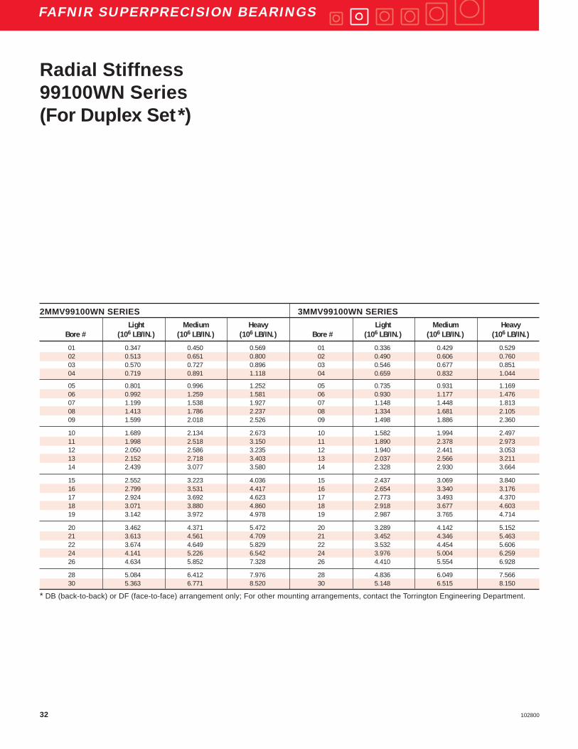
Radial Stiffness99100WN Series(For Duplex Set*)

33102800
FAFNIR SUPERPRECISION BEARINGS
2MM99100WN SERIES 3MM99100WN SERIES
X-Light to Light to Medium to X-Light to Light to Medium toBore # Light Medium Heavy Bore # Light Medium Heavy
(IN.) (IN.) (IN.) (IN.) (IN.) (IN.)
01 0.00018 0.00022 0.00033 01 0.00011 0.00017 0.0002602 0.00016 0.00020 0.00030 02 0.00010 0.00015 0.0002303 0.00014 0.00018 0.00027 03 0.00009 0.00013 0.0002104 0.00018 0.00027 0.00040 04 0.00013 0.00020 0.00031
05 0.00022 0.00031 0.00045 05 0.00015 0.00023 0.0003506 0.00019 0.00027 0.00040 06 0.00013 0.00020 0.0003107 0.00018 0.00027 0.00040 07 0.00014 0.00021 0.0003208 0.00020 0.00029 0.00042 08 0.00014 0.00022 0.0003409 0.00022 0.00033 0.00048 09 0.00016 0.00025 0.00038
10 0.00021 0.00031 0.00046 10 0.00015 0.00024 0.0003611 0.00024 0.00036 0.00052 11 0.00018 0.00028 0.0004212 0.00023 0.00035 0.00051 12 0.00017 0.00027 0.0004113 0.00025 0.00038 0.00055 13 0.00019 0.00030 0.0004514 0.00024 0.00037 0.00054 14 0.00019 0.00029 0.00044
15 0.00026 0.00039 0.00058 15 0.00020 0.00031 0.0005116 0.00029 0.00044 0.00044 16 0.00022 0.00034 0.0005117 0.00030 0.00045 0.00066 17 0.00023 0.00036 0.0004818 0.00034 0.00051 0.00074 18 0.00025 0.00039 0.0005719 0.00033 0.00050 0.00050 19 0.00025 0.00039 0.00056
20 0.00034 0.00051 0.00075 20 0.00025 0.00039 0.0006021 0.00035 0.00053 0.00081 21 0.00027 0.00044 0.0006522 0.00036 0.00055 0.00087 22 0.00028 0.00047 0.0006924 0.00038 0.00058 0.00082 24 0.00030 0.00045 0.0007026 0.00045 0.00067 0.00094 26 0.00034 0.00050 0.00079
28 0.00044 0.00067 0.00096 28 0.00034 0.00051 0.0007930 0.00045 0.00067 0.00100 30 0.00035 0.00054 0.00083
* DB (back-to-back) or DF (face-to-face) arrangement only; For other mounting arrangements, contact the Torrington Engineering Department.
Spacer Offsets99100WN Series(For Duplex Set*)
SU
PE
RP
RE
CIS
ION
BE
AR
ING
S
34 102800
FAFNIR SUPERPRECISION BEARINGS
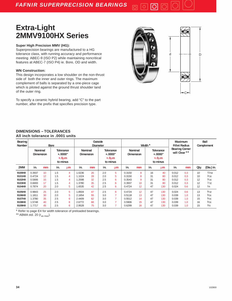
Extra-Light2MMV9100HX Series
DIMENSIONS – TOLERANCESAll inch tolerance in .0001 unitsBearing Outside Maximum BallNumber Bore Diameter Width * Fillet Radius Complement
Nominal Tolerance Nominal Tolerance Nominal Tolerance Bearing Corner
Dimension +.0000" Dimension +.0000" Dimension +.0000" will Clear **
+.0µm +.0µm +.0µmto minus to minus to minus
2MM in. mm in. µm in. mm in. µm in. mm in. µm in. mm Qty. (Dia.) in.
9100HX 0.3937 10 1.5 4 1.0236 26 2.0 5 0.3150 8 16 40 0.012 0.3 10 11⁄ 649101HX 0.4724 12 1.5 4 1.1024 28 2.0 5 0.3150 8 31 80 0.012 0.3 10 3⁄169102HX 0.5906 15 1.5 4 1.2598 32 2.5 6 0.3543 9 31 80 0.012 0.3 12 3⁄169103HX 0.6693 17 1.5 4 1.3780 35 2.5 6 0.3937 10 31 80 0.012 0.3 12 7⁄ 329104HX 0.7874 20 2.0 5 1.6535 42 2.5 6 0.4724 12 47 130 0.024 0.6 12 1⁄4
9105HX 0.9843 25 2.0 5 1.8504 47 2.5 6 0.4724 12 47 130 0.024 0.6 13 9⁄ 329106HX 1.1811 30 2.0 5 2.1654 55 3.0 7 0.5118 13 47 130 0.039 1.0 13 5⁄169107HX 1.3780 35 2.5 6 2.4409 62 3.0 7 0.5512 14 47 130 0.039 1.0 15 5⁄169108HX 1.5748 40 2.5 6 2.6772 68 3.0 7 0.5906 15 47 130 0.039 1.0 16 5⁄169109HX 1.7717 45 2.5 6 2.9528 75 3.0 7 0.6299 16 47 130 0.039 1.0 15 3⁄ 8
* Refer to page E4 for width tolerance of preloaded bearings.** ABMA std. 20 (ras max).
Super High Precision MMV (HG):Superprecision bearings are manufactured to a HGtolerance class, with running accuracy and performancemeeting ABEC-9 (ISO P2) while maintaining noncriticalfeatures at ABEC-7 (ISO P4) ie. Bore, OD and width.
WN Construction:This design incorporates a low shoulder on the non-thrustside of both the inner and outer rings. The maximumcomplement of balls is separated by a one-piece cagewhich is piloted against the ground thrust shoulder landof the outer ring.
To specify a ceramic hybrid bearing, add “C” to the partnumber, after the prefix that specifies precision type.
Dd
C

35102800
FAFNIR SUPERPRECISION BEARINGS
DIMENSIONS – TOLERANCESAll inch tolerance in .0001 unitsBearing Outside Maximum BallNumber Bore Diameter Width * Fillet Radius Complement
Nominal Tolerance Nominal Tolerance Nominal Tolerance Bearing Corner
Dimension +.0000" Dimension +.0000" Dimension +.0000" will Clear **
+.0µm +.0µm +.0µmto minus to minus to minus
2MM in. mm in. µm in. mm in. µm in. mm in. µm in. mm Qty. (Dia.) in.
9110HX 1.9685 50 2.5 6 3.1496 80 3.0 7 0.6299 16 47 130 0.039 1.0 16 3⁄89111HX 2.1654 55 3.0 7 3.5433 90 3.0 8 0.7087 18 59 150 0.039 1.0 24 5⁄ 169112HX 2.3622 60 3.0 7 3.7402 95 3.0 8 0.7087 18 59 150 0.039 1.0 25 5⁄ 169113HX 2.5591 65 3.0 7 3.9370 100 3.0 8 0.7087 18 59 150 0.039 1.0 25 11⁄ 329114HX 2.7559 70 3.0 7 4.3307 110 3.0 8 0.7874 20 59 150 0.039 1.0 25 3⁄8
9115HX 2.9528 75 3.0 7 4.5276 115 3.0 8 0.7874 20 59 150 0.039 1.0 26 3⁄89116HX 3.1496 80 3.0 7 4.9213 125 3.5 9 0.8661 22 59 150 0.039 1.0 25 7⁄ 169117HX 3.3465 85 3.0 8 5.1181 130 3.5 9 0.8610 22 79 210 0.039 1.0 26 7⁄ 169118HX 3.5433 90 3.0 8 5.5118 140 3.5 9 0.9449 24 79 210 0.059 1.5 28 7⁄ 169119HX 3.7402 95 3.0 8 5.7087 145 3.5 9 0.9449 24 79 210 0.059 1.5 26 1⁄2
9120HX 3.9370 100 3.0 8 5.9055 150 3.5 9 0.9449 24 79 210 0.059 1.5 27 1⁄29121HX 4.1339 105 3.0 8 6.2992 160 4.0 10 1.0236 26 79 210 0.079 2.0 28 1⁄29122HX 4.3307 110 3.0 8 6.6929 170 4.0 10 1.1024 28 79 210 0.079 2.0 30 1⁄29124HX 4.7244 120 3.0 8 7.0866 180 4.0 10 1.1024 28 79 210 0.079 2.0 29 9⁄ 16
* Refer to page E4 for width tolerance of preloaded bearings.** ABMA std. 20 (ras max).
SU
PE
RP
RE
CIS
ION
BE
AR
ING
S
Dd
C (WIDTH)X 2
Dd
C (WIDTH)X 2
Dd
C (WIDTH)X 2
Back-to-Back Face-to-Face TandemDB DF DT
WN Type Duplex Mounting Arrangement

36 102800
FAFNIR SUPERPRECISION BEARINGS
PHYSICAL CHARACTERISTICS – LOAD RATINGSBearing Weight Static Extended Dynamic Permis- Preload Levels **Number Per Bearing Load Rating Load Rating sible
Co Ce Speed Light Medium HeavyNg * (DUL) (DUM) (DUH)
lbs kg lbs N lbs N RPM lbs N lbs N lbs N
2MMV9100HX 0.04 0.018 305 1,400 965 4,300 88,000 5 20 15 70 30 1302MMV9101HX 0.04 0.020 365 1,600 1,140 5,100 78,900 5 20 15 70 30 1302MMV9102HX 0.06 0.027 465 2,100 1,290 5,700 64,300 5 20 15 70 30 1302MMV9103HX 0.08 0.038 620 2,800 1,700 7,600 58,900 5 20 15 70 30 1302MMV9104HX 0.14 0.064 830 3,700 2,160 9,600 48,900 10 40 30 90 60 270
2MMV9105HX 0.16 0.073 1,140 5,100 2,850 12,700 41,800 10 40 30 130 60 2702MMV9106HX 0.23 0.104 1,430 6,400 3,450 15,300 34,900 15 70 45 200 90 4002MMV9107HX 0.32 0.145 1,730 7,700 3,750 16,700 29,800 15 70 45 200 90 4002MMV9108HX 0.40 0.181 1,900 8,500 3,900 17,300 26,200 15 70 45 200 90 4002MMV9109HX 0.48 0.218 2,500 11,100 5,200 23,100 23,900 20 90 60 270 120 530
2MMV9110HX 0.52 0.236 2,700 12,000 5,400 24,000 21,800 20 90 60 270 120 5302MMV9111HX 0.88 0.399 3,000 13,300 4,800 21,400 18,700 25 110 75 330 150 6702MMV9112HX 0.94 0.426 3,150 14,000 4,900 21,800 17,400 25 110 75 330 150 6702MMV9113HX 0.98 0.445 3,800 16,900 5,850 26,000 16,400 30 130 90 400 180 8002MMV9114HX 1.38 0.626 4,500 20,000 6,800 30,200 15,000 35 160 105 470 210 930
2MMV9115HX 1.45 0.658 4,650 20,700 6,950 30,900 14,200 35 160 105 470 210 9302MMV9116HX 1.93 0.875 6,100 27,100 9,150 40,700 13,200 45 200 135 600 270 12002MMV9117HX 2.02 0.916 6,400 28,500 9,300 41,400 12,600 50 220 150 670 300 13302MMV9118HX 2.71 1.229 6,950 30,900 9,500 42,300 11,700 50 220 150 670 300 13302MMV9119HX 2.73 1.238 8,300 36,900 11,800 52,500 11,300 60 270 180 800 360 1600
2MMV9120HX 2.84 1.288 8,650 38,500 12,000 53,000 10,800 60 270 180 800 360 16002MMV9121HX 3.69 1.674 9,000 40,000 12,200 54,300 10,100 60 270 180 800 360 16002MMV9122HX 4.70 2.132 9,650 42,900 12,500 55,600 9,500 65 290 195 870 390 17302MMV9124HX 4.89 2.218 11,800 52,500 15,300 68,100 8,900 80 360 240 1070 480 2140
* Limits shown for a single row, spring preloaded and grease lubricated bearing.** All ceramic hybrid bearing preloads are equivalent to the table above.
Extra-Light2MMV9100HX Series
RADIAL LOAD RATING AT 33 1⁄ 3 RPMBased on 1500 hours L 10 Life and Permissible Speed
37102800
FAFNIR SUPERPRECISION BEARINGS
EXTRA-LIGHT – 2MMV9100HX SERIESBearing FTF BSF BPFO BPFI FTF
NumberFundamental Train Ball Spin Ball Pass Frequency Ball Pass Frequency Fundamental Train
Frequency Frequency Outer Inner Frequency(Inner Rotation) (Outer Rotation)
2MMV9100HX 0.3834 1.9496 3.8344 6.1656 0.61662MMV9101HX 0.3852 1.9890 3.8517 6.1483 0.61482MMV9102HX 0.4023 2.3729 4.8273 7.1727 0.59772MMV9103HX 0.3969 2.2403 4.7634 7.2366 0.60312MMV9104HX 0.4012 2.3457 4.8147 7.1853 0.5988
2MMV9105HX 0.4043 2.4274 5.2560 7.7440 0.59572MMV9106HX 0.4099 2.5903 5.3292 7.6708 0.59012MMV9107HX 0.4211 2.9789 6.3162 8.6838 0.57892MMV9108HX 0.4291 3.3332 6.8659 9.1341 0.57092MMV9109HX 0.4234 3.0758 6.3517 8.6483 0.5766
2MMV9110HX 0.4293 3.3440 6.8694 9.1306 0.57072MMV9111HX 0.4472 4.5160 10.7329 13.2671 0.55282MMV9112HX 0.4506 4.8343 11.2653 13.7347 0.54942MMV9113HX 0.4490 4.6751 11.2241 13.7759 0.55102MMV9114HX 0.4490 4.6752 11.2241 13.7759 0.5510
2MMV9115HX 0.4517 4.9403 11.7429 14.2571 0.54832MMV9116HX 0.4477 4.5613 11.1913 13.8087 0.55232MMV9117HX 0.4502 4.7888 11.7039 14.2961 0.54982MMV9118HX 0.4534 5.1295 12.6953 15.3047 0.54662MMV9119HX 0.4490 4.6752 11.6731 14.3269 0.5510
2MMV9120HX 0.4510 4.8740 12.1772 14.8228 0.54902MMV9121HX 0.4538 5.1719 12.7058 15.2942 0.54622MMV9122HX 0.4563 5.4696 13.6877 16.3123 0.54372MMV9124HX 0.4542 5.2052 13.1707 15.8293 0.5458
Frequency Coefficients Superprecision Bearings
FTF Fundamental Train Frequency: The frequency at which theretainer will operate.
BSF Ball Spin Frequency: The frequency at which a singledefect on a rolling element will be detected.
BPFO Ball Pass Frequency Outer: The frequency at which asingle defect in the outer race will be detected.
BPFI Ball Pass Frequency Inner: The frequency at which asingle defect in the inner race will be detected.
SU
PE
RP
RE
CIS
ION
BE
AR
ING
S
Extra-Light2MMV9100HX Series

38 102800
FAFNIR SUPERPRECISION BEARINGS
PERMISSIBLE OPERATING SPEEDS – RPM2MMV9100HX Series
GREASE OIL
“DB” Mounting Grease Capacity Kluber Isoflex NBU 15 “DB” Mounting15 Degree
Contact Angle (DUL) (DUM) (DUH) 25% 40% 15% 20% (DUL) (DUM) (DUH)Light Medium Heavy (grams) (grams) (grams) (grams) Light Medium Heavy
2MMV9100HX 70,400 52,800 35,200 0.3 0.4 0.16 0.21 119,700 89,800 59,8002MMV9101HX 63,100 47,300 31,600 0.3 0.5 0.18 0.24 107,300 80,400 53,7002MMV9102HX 51,400 38,600 25,700 0.4 0.7 0.25 0.33 87,400 65,600 43,7002MMV9103HX 47,100 35,300 23,600 0.6 0.9 0.33 0.44 80,100 60,000 40,1002MMV9104HX 39,100 29,300 19,600 1.0 1.6 0.57 0.77 66,500 49,800 33,300
2MMV9105HX 33,400 25,100 16,700 1.2 1.9 0.70 0.93 56,800 42,700 28,4002MMV9106HX 27,900 20,900 14,000 1.7 2.7 1.01 1.34 47,400 35,500 23,8002MMV9107HX 23,800 17,900 11,900 2.1 3.4 1.25 1.67 40,500 30,400 20,2002MMV9108HX 21,000 15,700 10,500 2.7 4.3 1.54 2.06 35,700 26,700 17,9002MMV9109HX 19,100 14,300 9,600 3.5 5.6 2.12 2.83 32,500 24,300 16,300
2MMV9110HX 17,400 13,100 8,700 3.9 6.2 2.3 3.1 29,600 22,300 14,8002MMV9111HX 15,000 11,200 7,500 4.6 7.3 2.5 3.3 25,500 19,000 12,8002MMV9112HX 13,900 10,400 7,000 4.9 7.9 2.7 3.6 23,600 17,700 11,9002MMV9113HX 13,100 9,800 6,600 5.5 8.8 3.1 4.1 22,300 16,700 11,2002MMV9114HX 12,000 9,000 6,000 7.3 11.7 4.1 5.4 20,400 15,300 10,200
2MMV9115HX 11,400 8,500 5,700 7.7 12.4 4.3 5.7 19,400 14,500 9,7002MMV9116HX 10,600 7,900 5,300 10.3 16.5 5.8 7.7 18,000 13,400 9,0002MMV9117HX 10,100 7,600 5,000 10.8 17.3 6.1 8.1 17,200 12,900 8,5002MMV9118HX 9,400 7,000 4,700 13.2 21.0 7.2 9.7 16,000 11,900 8,0002MMV9119HX 9,000 6,800 4,500 14.6 23.4 8.3 11.1 15,300 11,600 7,700
2MMV9120HX 8,600 6,500 4,300 15.2 24.4 8.6 11.5 14,600 11,100 7,3002MMV9121HX 8,100 6,100 4,000 18.3 29.3 10.2 13.6 13,800 10,400 6,8002MMV9122HX 7,600 5,700 3,800 21.5 34.3 11.8 15.7 12,900 9,700 6,5002MMV9124HX 7,100 5,300 3,600 24.4 39.1 13.7 18.3 12,100 9,000 6,100
Note: For 2MMVC and 3MMVC Spindle bearings, use 120% of Permissible Operating Speeds.For other bearing configurations beside a back-to-back mounted duplex set, please refer to page E36 to calculate thepermissible operating speed (Sp.).
Extra-Light2MMV9100HX Series

39102800
FAFNIR SUPERPRECISION BEARINGS
2MMV9100HX SERIESBore Light Medium Heavy
Number (106 lb/in.) (106 lb/in.) (106 lb/in.)
00 0.0860 0.1345 0.183401 0.0824 0.1290 0.176002 0.0923 0.1434 0.194303 0.0958 0.1471 0.197404 0.1287 0.2010 0.2735
05 0.1399 0.2154 0.289606 0.1665 0.2586 0.350407 0.1820 0.2811 0.379208 0.1895 0.2920 0.393009 0.2122 0.3268 0.4396
10 0.2209 0.3395 0.455811 0.2960 0.4578 0.618312 0.3036 0.4689 0.632413 0.3329 0.5140 0.693014 0.3604 0.5561 0.7493
15 0.3694 0.5691 0.765816 0.4011 0.6192 0.834917 0.4388 0.6773 0.913018 0.4596 0.7075 0.951319 0.4857 0.7474 1.0047
20 0.4974 0.7643 1.026121 0.5088 0.7809 1.047322 0.5475 0.8405 1.127624 0.6213 0.9503 1.2707
* DB (back-to-back) or DF (face-to-face) arrangement only; For other mounting arrangements, contact the Torrington Engineering Department.
Axial Stiffness2MMV9100HX Series(For Duplex Set*)
SU
PE
RP
RE
CIS
ION
BE
AR
ING
S

40 102800
FAFNIR SUPERPRECISION BEARINGS
2MMV9100HX SERIESBore Light Medium Heavy
Number (106 LB/IN.) (106 LB/IN.) (106 LB/IN.)
00 0.4690 0.6743 0.841401 0.4924 0.7094 0.886002 0.5552 0.8029 1.004203 0.5803 0.8462 1.061004 0.7711 1.1124 1.3900
05 0.8471 1.2328 1.545006 1.0017 1.4486 1.811907 1.0995 1.5956 1.998008 1.1464 1.6666 2.088209 1.2837 1.8669 2.3394
10 1.3380 1.9498 2.444511 1.7862 2.5895 3.241712 1.8341 2.6618 3.333213 2.0115 2.9198 3.656614 2.1789 3.1645 3.9637
15 2.2347 3.2491 4.071016 2.5122 3.6526 4.576217 2.6524 3.8513 4.823618 2.7819 4.0479 5.072919 2.9406 4.2802 5.3645
20 3.0125 4.3899 5.503821 3.0831 4.4984 5.641622 3.3169 4.8377 6.066524 3.5654 5.2038 6.5275
* DB (back-to-back) or DF (face-to-face) arrangement only; For other mounting arrangements, contact the Torrington Engineering Department.
Radial Stiffness2MMV9100HX Series(For Duplex Set*)
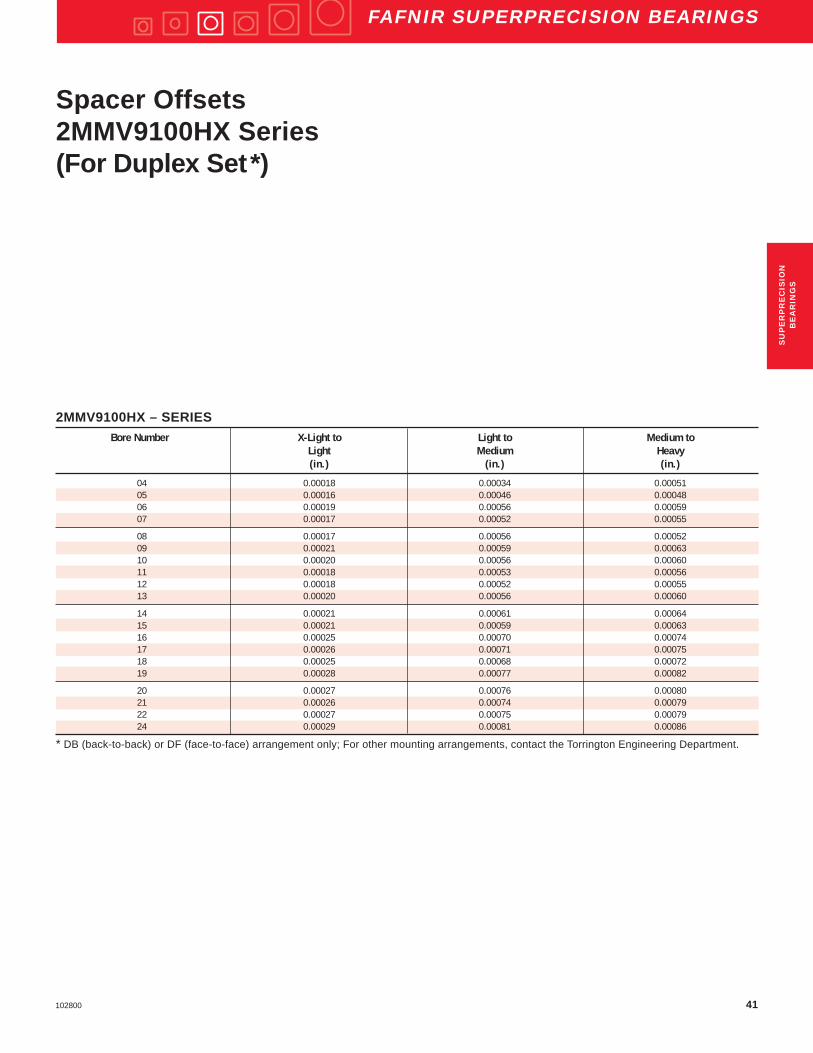
41102800
FAFNIR SUPERPRECISION BEARINGS
2MMV9100HX – SERIESBore Number X-Light to Light to Medium to
Light Medium Heavy(in.) (in.) (in.)
04 0.00018 0.00034 0.0005105 0.00016 0.00046 0.0004806 0.00019 0.00056 0.0005907 0.00017 0.00052 0.00055
08 0.00017 0.00056 0.0005209 0.00021 0.00059 0.0006310 0.00020 0.00056 0.0006011 0.00018 0.00053 0.0005612 0.00018 0.00052 0.0005513 0.00020 0.00056 0.00060
14 0.00021 0.00061 0.0006415 0.00021 0.00059 0.0006316 0.00025 0.00070 0.0007417 0.00026 0.00071 0.0007518 0.00025 0.00068 0.0007219 0.00028 0.00077 0.00082
20 0.00027 0.00076 0.0008021 0.00026 0.00074 0.0007922 0.00027 0.00075 0.0007924 0.00029 0.00081 0.00086
* DB (back-to-back) or DF (face-to-face) arrangement only; For other mounting arrangements, contact the Torrington Engineering Department.
Spacer Offsets2MMV9100HX Series(For Duplex Set*)
SU
PE
RP
RE
CIS
ION
BE
AR
ING
S

42 102800
FAFNIR SUPERPRECISION BEARINGS
DIMENSIONS – TOLERANCESAll inch tolerance in .0001 unitsBearing Outside Maximum BallNumber Bore Diameter Width * Fillet Radius Complement
Nominal Tolerance Nominal Tolerance Nominal Tolerance Bearing Corner
Dimension +.0000" Dimension +.0000" Dimension +.0000" will Clear **
+.0µm +.0µm +.0µmto minus to minus to minus
2MM &3MM in. mm in. µm in. mm in. µm in. mm in. µm in. mm Qty. (Dia.) in.
9100WI 0.3937 10 1.5 4 1.0236 26 2.0 5 0.3150 8 16 40 0.012 0.3 8 3⁄ 169101WI 0.4724 12 1.5 4 1.1024 28 2.0 5 0.3150 8 31 80 0.012 0.3 10 3⁄ 169102WI 0.5906 15 1.5 4 1.2598 32 2.5 6 0.3543 9 31 80 0.012 0.3 12 3⁄ 169103WI 0.6693 17 1.5 4 1.3780 35 2.5 6 0.3937 10 31 80 0.012 0.3 11 3⁄ 169104WI 0.7874 20 2.0 5 1.6535 42 2.5 6 0.4724 12 47 120 0.024 0.6 11 1⁄4
9105WI 0.9843 25 2.0 5 1.8504 47 2.5 6 0.4724 12 47 120 0.024 0.6 13 1⁄49106WI 1.1811 30 2.0 5 2.1654 55 3.0 7 0.5118 13 47 120 0.039 1.0 14 9⁄ 329107WI 1.3780 35 2.5 6 2.4409 62 3.0 7 0.5512 14 47 120 0.039 1.0 15 5⁄ 169108WI 1.5748 40 2.5 6 2.6772 68 3.0 7 0.5906 15 47 120 0.039 1.0 16 5⁄ 169109WI 1.7717 45 2.5 6 2.9528 75 3.0 7 0.6299 16 47 120 0.039 1.0 17 11⁄ 32
9110WI 1.9685 50 2.5 6 3.1496 80 3.0 7 0.6299 16 47 120 0.039 1.0 18 11⁄ 329111WI 2.1654 55 3.0 7 3.5433 90 3.0 8 0.7087 18 59 150 0.039 1.0 18 13⁄ 329112WI 2.3622 60 3.0 7 3.7402 95 3.0 8 0.7087 18 59 150 0.039 1.0 19 13⁄ 329113WI 2.5591 65 3.0 7 3.9370 100 3.0 8 0.7087 18 59 150 0.039 1.0 20 13⁄ 329114WI 2.7559 70 3.0 7 4.3307 110 3.0 8 0.7874 20 59 150 0.039 1.0 19 15⁄ 32
* Refer to page E4 for width tolerance of preloaded bearings.** ABMA std. 20 (ras max).
Extra-Light2MM9100WI &3MM9100WI Series
Dd
C
Superprecision MM:Superprecision bearings are manufactured to a ABEC-7(ISO P4) tolerance class.
WI Construction:This design incorporates a low shoulder on the non-thrustside of the outer rings. The maximum complement of ballsis separated by a one-piece cage which is piloted againstthe ground land of the outer ring.
To specify a ceramic hybrid bearing, add “C” to the partnumber, after the prefix that specifies precision type.

43102800
FAFNIR SUPERPRECISION BEARINGS
DIMENSIONS – TOLERANCESAll inch tolerance in .0001 unitsBearing Outside Maximum BallNumber Bore Diameter Width * Fillet Radius Complement
Nominal Tolerance Nominal Tolerance Nominal Tolerance Bearing Corner
Dimension +.0000" Dimension +.0000" Dimension +.0000" will Clear **
+.0µm +.0µm +.0µmto minus to minus to minus
2MM &3MM in. mm in. µm in. mm in. µm in. mm in. µm in. mm Qty. (Dia.) in.
9115WI 2.9528 75 3.0 7 4.5276 115 3.0 8 0.7874 20 59 150 0.039 1.0 20 15⁄ 329116WI 3.1496 80 3.0 7 4.9213 125 3.5 9 0.8661 22 59 150 0.039 1.0 20 17⁄ 329117WI 3.3465 85 3.0 8 5.1181 130 3.5 9 0.8661 22 79 200 0.039 1.0 21 17⁄ 329118WI 3.5433 90 3.0 8 5.5118 140 3.5 9 0.9449 24 79 200 0.059 1.5 20 19⁄ 329119WI 3.7402 95 3.0 8 5.7087 145 3.5 9 0.9449 24 79 200 0.059 1.5 21 19⁄ 32
9120WI 3.9370 100 3.0 8 5.9055 150 3.5 9 0.9449 24 79 200 0.059 1.5 22 19⁄ 329121WI 4.1339 105 3.0 8 6.2992 160 4.0 10 1.0236 26 79 200 0.079 2.0 21 21⁄ 329122WI 4.3307 110 3.0 8 6.6929 170 4.0 10 1.1024 28 79 200 0.079 2.0 22 11⁄ 169124WI 4.7244 120 3.0 8 7.0866 180 4.0 10 1.1024 28 79 200 0.079 2.0 23 11⁄ 169126WI 5.1181 130 4.0 10 7.8740 200 4.5 11 1.2992 33 98 250 0.079 2.0 21 13⁄ 16
9128WI 5.5118 140 4.0 10 8.2677 210 4.5 11 1.2992 33 98 250 0.079 2.0 22 13⁄ 169130WI 5.9055 150 4.0 10 8.8583 225 4.5 11 1.3780 35 98 250 0.079 2.0 22 7⁄ 89132WI 6.2992 160 4.0 10 9.4488 240 4.5 11 1.4961 38 98 250 0.079 2.0 22 15⁄ 169134WI 6.6929 170 4.0 10 10.2362 260 5.0 13 1.6535 42 98 250 0.079 2.0 22 1 1⁄ 169136WI 7.0866 180 4.0 10 11.0236 280 5.0 13 1.8110 46 98 250 0.079 2.0 20 1 3⁄ 169140WI 7.8740 200 4.5 12 12.2047 310 5.0 13 2.0079 51 118 300 0.079 2.0 20 1 5⁄ 16
* Refer to page E4 for width tolerance of preloaded bearings.** ABMA std. 20 (ras max).
C (WIDTH) X 2
d DD d D d D
C (WIDTH) X 2
C (WIDTH) X 2
WI Type Duplex Mounting Arrangements
Back-to-Back Face-to-Face TandemDB DF DT
SU
PE
RP
RE
CIS
ION
BE
AR
ING
S

44 102800
FAFNIR SUPERPRECISION BEARINGS
PHYSICAL CHARACTERISTICS – LOAD RATINGSBearing Weight Static Extended Permis- Preload Levels **Number Per Bearing Load Rating Dynamic sible
Load Ratings SpeedNg *
Co Ce Extralight Light Medium Heavy(DUX) (DUL) (DUM) (DUH)
lbs kg lbs N lbs N RPM lbs N lbs N lbs N lbs N
2MM9100WI 0.04 0.018 490 2,200 1,210 5,400 68,500 — — 3 13 6 25 12 552MM9101WI 0.04 0.020 650 2,900 1,430 6,400 57,300 — — 5 20 10 45 20 902MM9102WI 0.07 0.030 820 3,600 1,630 7,300 48,600 — — 5 20 15 65 30 1302MM9103WI 0.08 0.038 770 3,400 1,530 6,800 43,100 — — 5 20 20 90 35 1602MM9104WI 0.15 0.067 1,350 6,000 2,600 11,600 37,100 — — 10 45 20 90 40 180
2MM9105WI 0.17 0.077 1,660 7,400 2,900 12,900 30,900 — — 10 45 25 110 60 2702MM9106WI 0.25 0.113 2,310 10,300 3,770 16,800 25,500 — — 15 65 30 130 75 3302MM9107WI 0.33 0.151 3,070 13,700 4,760 21,200 22,600 — — 20 90 50 220 90 4002MM9108WI 0.41 0.187 3,360 14,900 4,920 21,900 19,900 — — 20 90 50 220 100 4402MM9109WI 0.53 0.240 4,330 19,300 6,080 27,000 17,900 — — 30 130 60 270 125 560
2MM9110WI 0.57 0.258 4,670 20,800 6,270 27,900 16,300 20 89 30 130 60 270 150 6702MM9111WI 0.84 0.383 6,420 28,600 8,500 37,800 14,700 25 110 35 160 75 330 150 6702MM9112WI 0.90 0.409 6,860 30,500 8,730 38,800 13,600 25 110 40 180 75 330 200 8902MM9113WI 0.96 0.435 7,330 32,600 8,950 39,800 12,700 25 110 50 220 100 440 200 8902MM9114WI 1.33 0.604 9,150 40,700 11,300 50,300 11,700 30 130 60 270 125 560 250 1110
2MM9115WI 1.41 0.638 9,790 43,500 11,600 51,600 11,000 30 130 60 270 125 560 275 12202MM9116WI 1.89 0.859 12,400 55,200 14,600 64,900 10,300 35 160 70 310 150 670 350 15602MM9117WI 1.99 0.901 13,200 58,700 15,000 66,700 9,700 40 180 80 360 175 780 375 16702MM9118WI 2.58 1.170 15,500 68,900 17,900 79,600 9,200 40 180 100 440 200 890 400 17802MM9119WI 2.69 1.222 16,500 73,400 18,300 81,400 8,700 45 200 110 490 220 980 445 1980
2MM9120WI 2.86 1.299 17,400 77,400 18,800 83,600 8,300 50 220 125 560 250 1110 450 20002MM9121WI 3.57 1.617 20,100 89,400 22,000 97,900 7,900 55 240 135 600 275 1220 550 24502MM9122WI 4.50 2.043 23,100 102,700 24,600 109,400 7,500 60 270 150 670 300 1330 600 26702MM9124WI 4.81 2.180 24,400 108,500 25,000 111,200 6,900 65 290 175 780 350 1560 650 28902MM9126WI 7.21 3.273 30,800 137,000 32,200 143,200 6,400 75 330 200 890 400 1780 825 3670
2MM9128WI 7.62 3.454 32,600 145,000 32,900 146,300 5,900 85 380 225 1000 450 2000 875 38902MM9130WI 9.26 4.200 37,800 168,100 37,600 167,200 5,600 100 440 250 1110 550 2450 1000 44502MM9132WI 11.44 5.188 43,300 192,600 42,600 189,500 5,200 110 490 300 1330 600 2670 1200 53402MM9134WI 15.43 6.999 55,200 245,500 52,600 234,000 4,900 130 580 375 1670 750 3340 1500 66702MM9136WI 20.40 9.250 62,100 276,200 58,100 258,400 4,600 150 670 390 1730 780 3470 1560 69402MM9140WI 26.78 12.148 75,800 337,200 66,700 296,700 4,100 210 930 500 2220 1000 4450 2000 8900
* Limits shown for a single row, spring preloaded and grease lubricated bearing.** All ceramic hybrid bearing preloads are equivalent to the table above.
Extra-Light2MM9100WI Series
RADIAL LOAD RATING AT 33 1⁄3 RPMBased on 1500 hours L 10 Life and Permissible Speed

45102800
FAFNIR SUPERPRECISION BEARINGS
FREQUENCY COEFFICIENTSBearing FTF BSF BPFO BPFI FTFNumber
Fundamental Train Ball Spin Ball Pass Frequency Ball Pass Frequency Fundamental TrainFrequency Frequency Outer Inner Frequency
(Inner Rotation) (Outer Rotation)
2MM9100WI 0.3740 1.7697 2.9924 5.0076 0.62602MM9101WI 0.3902 2.0621 3.9015 6.0985 0.60982MM9102WI 0.4035 2.3754 4.8424 7.1576 0.59652MM9103WI 0.4126 2.6411 4.5390 6.4610 0.58742MM9104WI 0.4013 2.3458 4.4140 6.5860 0.5987
2MM9105WI 0.4150 2.7526 5.3947 7.6053 0.58502MM9106WI 0.4201 2.9387 5.8807 8.1193 0.57992MM9107WI 0.4210 2.9789 6.3157 8.6843 0.57902MM9108WI 0.4291 3.3332 6.8655 9.1345 0.57092MM9109WI 0.4298 3.3682 7.3063 9.6937 0.5702
2MM9110WI 0.4352 3.6596 7.8332 10.1668 0.56482MM9111WI 0.4314 3.4469 7.7648 10.2352 0.56862MM9112WI 0.4358 3.6934 8.2803 10.7197 0.56422MM9113WI 0.4397 3.9394 8.7939 11.2061 0.56032MM9114WI 0.4362 3.7179 8.2875 10.7125 0.5638
2MM9115WI 0.4395 3.9312 8.7908 11.2092 0.56052MM9116WI 0.4365 3.7369 8.7306 11.2694 0.56352MM9117WI 0.4396 3.9332 9.2317 11.7683 0.56042MM9118WI 0.4367 3.7517 8.7350 11.2650 0.56332MM9119WI 0.4394 3.9200 9.2271 11.7729 0.5606
2MM9120WI 0.4418 4.0881 9.7198 12.2802 0.55822MM9121WI 0.4393 3.9167 9.2256 11.7744 0.56072MM9122WI 0.4399 3.9507 9.6778 12.3222 0.56012MM9124WI 0.4439 4.2417 10.2102 12.7898 0.55612MM9126WI 0.4397 3.9394 9.2336 11.7664 0.5603
2MM9128WI 0.4431 4.1850 9.7491 12.2509 0.55692MM9130WI 0.4428 4.1640 9.7426 12.2574 0.55722MM9132WI 0.4426 4.1450 9.7367 12.2633 0.55742MM9134WI 0.4394 3.9247 9.6660 12.3340 0.56062MM9140WI 0.4369 3.7645 8.7378 11.2622 0.5631
Extra-Light2MM9100WI SeriesSuperprecision Bearings
FTF Fundamental Train Frequency: The frequency atwhich the retainer will operate.
BSF Ball Spin Frequency: The frequency at which asingle defect on a rolling element will be detected.
BPFO Ball Pass Frequency Outer: The frequency atwhich a single defect in the outer race will bedetected.
BPFI Ball Pass Frequency Inner: The frequency atwhich a single defect in the inner race will bedetected.
SU
PE
RP
RE
CIS
ION
BE
AR
ING
S

46 102800
FAFNIR SUPERPRECISION BEARINGS
PHYSICAL CHARACTERISTICS – LOAD RATINGSBearing Weight Static Extended Permis- Preload Levels **Number Per Bearing Load Rating Dynamic sible
Load Ratings SpeedNg *
Co Ce Extralight Light Medium Heavy(DUX) (DUL) (DUM) (DUH)
lbs kg lbs N lbs N RPM lbs N lbs N lbs N lbs N
3MM9100WI 0.04 0.018 480 2,100 1,190 5,300 61,700 — — 5 20 10 45 20 903MM9101WI 0.04 0.020 630 2,800 1,390 6,200 51,600 — — 10 45 20 90 40 1803MM9102WI 0.07 0.030 790 3,530 1,580 7,020 43,700 — — 10 45 20 90 40 1803MM9103WI 0.08 0.038 750 3,300 1,480 6,600 38,800 — — 15 65 35 160 50 2203MM9104WI 0.15 0.067 1,290 5,700 2,500 11,100 33,400 — — 20 90 40 180 75 330
3MM9105WI 0.17 0.077 1,590 7,100 2,770 12,300 27,800 — — 20 90 50 220 90 4003MM9106WI 0.25 0.113 2,200 9,900 3,600 16,000 23,000 — — 30 130 65 290 120 5303MM9107WI 0.33 0.151 2,930 13,000 4,540 20,200 20,300 — — 35 160 80 360 160 7103MM9108WI 0.41 0.187 3,190 14,200 4,670 20,800 17,900 — — 40 180 100 440 170 7603MM9109WI 0.53 0.240 4,110 18,300 5,760 25,600 16,100 — — 50 220 125 560 220 980
3MM9110WI 0.57 0.258 4,430 19,700 5,910 26,300 14,700 25 110 55 240 150 670 240 10703MM9111WI 0.84 0.383 6,110 27,200 8,080 35,900 13,200 30 130 75 330 175 780 300 13303MM9112WI 0.90 0.409 7,470 33,200 8,290 36,900 12,200 35 160 80 360 200 890 325 14503MM9113WI 0.96 0.435 6,970 31,000 8,480 37,700 11,400 40 180 80 360 200 890 350 15603MM9114WI 1.33 0.604 8,730 38,800 10,700 47,600 10,500 45 200 100 440 250 1110 450 2000
3MM9115WI 1.41 0.638 9,260 41,200 11,000 48,900 9,900 50 220 110 490 275 1220 475 21103MM9116WI 1.89 0.859 11,800 52,500 13,800 61,400 9,300 55 240 140 620 350 1560 600 26703MM9117WI 1.99 0.901 12,500 55,600 14,200 63,200 8,700 60 270 150 670 375 1670 650 28903MM9118WI 2.58 1.170 14,800 65,800 16,900 75,200 8,300 65 270 170 760 400 1780 750 33403MM9119WI 2.69 1.222 15,600 69,400 17,400 77,400 7,800 65 290 185 820 445 1980 775 3450
3MM9120WI 2.86 1.299 16,500 73,400 17,800 79,200 7,500 75 330 190 850 450 2000 800 35603MM9121WI 3.57 1.617 19,000 84,500 20,700 92,100 7,100 80 360 215 960 460 2050 920 40903MM9122WI 4.50 2.043 21,900 97,400 23,200 103,200 6,800 90 400 250 1110 600 2670 1100 48903MM9124WI 4.81 2.180 23,200 103,200 23,600 105,000 6,200 100 440 275 1220 650 2890 1150 51203MM9126WI 7.21 3.273 29,200 129,900 30,500 135,700 5,800 115 510 340 1510 825 3670 1500 6670
3MM9128WI 7.62 3.454 30,900 137,400 31,100 138,300 5,300 130 580 350 1560 875 3890 1550 68903MM9130WI 9.26 4.200 35,800 159,200 35,500 157,900 5,000 145 640 400 1780 1000 4450 1800 80103MM9132WI 11.44 5.188 41,100 182,800 40,300 179,300 4,700 170 760 500 2220 1200 5340 2000 89003MM9134WI 15.43 6.999 52,300 232,600 49,700 221,100 4,400 210 930 625 2780 1300 5780 2600 115603MM9136WI 20.40 9.250 59,000 262,400 55,000 244,400 4,200 230 1020 700 3110 1400 6230 2800 124603MM9140WI 26.78 12.148 72,200 321,100 63,200 281,100 3,700 280 1250 850 3780 2000 8900 3600 16010
* Limits shown for a single row, spring preloaded and grease lubricated bearing.** All ceramic hybrid bearing preloads are equivalent to the table above.
Extra-Light3MM9100WI Series
RADIAL LOAD RATING AT 33 1⁄ 3 RPMBased on 1500 hours L 10 Life and Permissible Speed

47102800
FAFNIR SUPERPRECISION BEARINGS
FREQUENCY COEFFICIENTSBearing FTF BSF BPFO BPFI FTFNumber
Fundamental Train Ball Spin Ball Pass Frequency Ball Pass Frequency Fundamental TrainFrequency Frequency Outer Inner Frequency
(Inner Rotation) (Outer Rotation)
3MM9100WI 0.3740 1.7697 2.9924 5.0076 0.62603MM9101WI 0.3957 2.0724 3.9569 6.0431 0.60433MM9102WI 0.4084 2.3844 4.4924 6.5076 0.59163MM9103WI 0.4170 2.6493 4.5875 6.4125 0.58303MM9104WI 0.4074 2.3573 4.4816 6.5184 0.5926
3MM9105WI 0.4203 2.7625 5.4635 7.5365 0.57973MM9106WI 0.4243 2.9475 5.9467 8.0533 0.57523MM9107WI 0.4258 2.9877 6.3864 8.6136 0.57423MM9108WI 0.4333 3.3411 6.9332 9.0668 0.56673MM9109WI 0.4340 3.3761 7.3782 9.6218 0.5660
3MM9110WI 0.4391 3.6669 7.9036 10.0964 0.56093MM9111WI 0.4354 3.4544 7.8373 10.1627 0.56463MM9112WI 0.4396 3.7005 8.3519 10.6481 0.56043MM9113WI 0.4432 3.9461 8.8647 11.1353 0.55683MM9114WI 0.4400 3.7251 8.3599 10.6401 0.5600
3MM9115WI 0.4432 3.9379 8.8630 11.1370 0.55683MM9116WI 0.4404 3.7441 8.8074 11.1926 0.55963MM9117WI 0.4433 3.9400 9.3085 11.6915 0.55673MM9118WI 0.4405 3.7587 8.8101 11.1899 0.55953MM9119WI 0.4430 3.9267 9.3026 11.6974 0.5570
3MM9120WI 0.4453 4.0945 9.7958 12.2042 0.55473MM9121WI 0.4430 3.9235 9.3021 11.6979 0.55703MM9122WI 0.4434 3.9573 9.7557 12.2443 0.55663MM9124WI 0.4472 4.2479 10.2861 12.7139 0.55283MM9126WI 0.4433 3.9462 9.3096 11.6904 0.5567
3MM9128WI 0.4466 4.1914 9.8241 12.1759 0.55343MM9130WI 0.4463 4.1705 9.8186 12.1814 0.55373MM9132WI 0.4461 4.1515 9.8135 12.1865 0.55393MM9134WI 0.4431 3.9318 9.7492 12.2508 0.55693MM9136WI 0.4406 3.7588 8.8114 11.1886 0.55943MM9140WI 0.4408 3.7719 8.8164 11.1836 0.5592
Extra-Light3MM9100WI SeriesSuperprecision Bearings
FTF Fundamental Train Frequency: The frequency atwhich the retainer will operate.
BSF Ball Spin Frequency: The frequency at which asingle defect on a rolling element will be detected.
BPFO Ball Pass Frequency Outer: The frequency atwhich a single defect in the outer race will bedetected.
BPFI Ball Pass Frequency Inner: The frequency atwhich a single defect in the inner race will bedetected.
SU
PE
RP
RE
CIS
ION
BE
AR
ING
S

48 102800
FAFNIR SUPERPRECISION BEARINGS
GREASE OIL
“DB” Mounting Grease Capacity High Speed Grease “DB” Mounting15 Degree (DUL) (DUM) (DUH) 25 % 40 % 15 % 20 % (DUL) (DUM) (DUH)
Contact Angle Light Medium Heavy (grams) (grams) (grams) (grams) Light Medium Heavy
2MM9100WI 54,800 41,100 27,400 0.2 0.4 0.15 0.20 93,200 69,900 46,6002MM9101WI 45,800 34,400 22,900 0.3 0.4 0.17 0.22 77,900 58,500 38,9002MM9102WI 38,900 29,200 19,400 0.3 0.5 0.22 0.29 66,100 49,600 33,0002MM9103WI 34,500 25,900 17,200 0.4 0.7 0.28 0.37 58,700 44,000 29,2002MM9104WI 29,700 22,300 14,800 0.7 1.2 0.50 0.66 50,500 37,900 25,200
2MM9105WI 24,700 18,500 12,400 0.9 1.4 0.59 0.78 42,000 31,500 21,1002MM9106WI 20,400 15,300 10,200 1.3 2.0 0.84 1.12 34,700 26,000 17,3002MM9107WI 18,100 13,600 9,000 1.6 2.6 1.09 1.46 30,800 23,100 15,3002MM9108WI 15,900 11,900 8,000 2.0 3.2 1.35 1.80 27,000 20,200 13,6002MM9109WI 14,300 10,000 7,200 2.5 4.0 1.68 2.24 24,300 18,200 12,200
2MM9110WI 13,000 9,800 6,500 2.8 4.4 1.9 2.5 22,100 16,700 11,1002MM9111WI 11,800 8,800 5,900 4.0 6.4 2.7 3.5 20,100 15,000 10,0002MM9112WI 10,900 8,200 5,400 4.2 6.8 2.8 3.8 18,500 13,900 9,2002MM9113WI 10,200 7,600 5,100 4.5 7.2 3.0 4.0 17,300 12,900 8,7002MM9114WI 9,400 7,000 4,700 6.3 10.0 4.2 5.6 16,000 11,900 8,000
2MM9115WI 8,800 6,600 4,400 6.6 10.6 4.4 5.9 15,000 11,200 7,5002MM9116WI 8,200 6,200 4,100 8.6 13.8 5.8 7.7 13,900 10,500 7,0002MM9117WI 7,800 5,800 3,900 9.1 14.5 6.0 8.1 13,300 9,900 6,6002MM9118WI 7,400 5,500 3,700 11.7 18.8 7.8 10.4 12,600 9,400 6,3002MM9119WI 7,000 5,200 3,500 12.2 19.5 8.1 10.9 11,900 8,800 6,000
2MM9120WI 6,600 5,000 3,300 12.1 19.4 8.1 10.8 11,200 8,500 5,6002MM9121WI 6,300 4,700 3,200 15.9 25.4 10.6 14.1 10,700 8,000 5,4002MM9122WI 6,000 4,500 3,000 18.9 30.2 12.6 16.8 10,200 7,700 5,1002MM9124WI 5,500 4,100 2,800 20.5 32.8 13.7 18.2 9,400 7,000 4,8002MM9126WI 5,100 3,800 2,600 31.7 50.7 21.1 28.2 8,700 6,500 4,400
2MM9128WI 4,700 3,500 2,400 33.8 54.0 22.5 30.1 8,000 6,000 4,1002MM9130WI 4,500 3,400 2,200 41.1 65.7 27.4 36.5 7,700 5,800 3,7002MM9132WI 4,200 3,100 2,100 51.0 81.6 34.1 45.4 7,100 5,300 3,6002MM9134WI 3,900 2,900 2,000 66.3 106.0 44.2 59.0 6,600 4,900 3,4002MM9136WI 3,700 2,800 1,800 88.4 141.5 59.0 78.7 6,200 4,700 3,1002MM9140WI 3,300 2,500 1,600 121.0 193.5 80.7 107.6 5,600 4,300 2,700
Notes: For 3MM (25 Degree Contact Angle) Spindle Bearings, use 90% of the Permissible Operating Speeds above.* For 2MMC and 3MMC Spindle Bearings, use 120% of the Permissible Operating Speeds.
For other bearing configurations beside a back-to-back mounted duplex set, please refer to page E36 to calculate thepermissible operating speed (Sp.).
Extra-Light9100WI Series
PERMISSIBLE OPERATING SPEEDS – RPM2MM & 3MM Superprecision Angular Contact Spindle Bearings

49102800
FAFNIR SUPERPRECISION BEARINGS
2MM9100WI SERIES 3MM9100WI SERIESBore # X-Light Light Medium Heavy Bore # X-Light Light Medium Heavy
(106 LB/IN.) (106 LB/IN.) (106 LB/IN.) (106 LB/IN.) (106 LB/IN.) (106 LB/IN.) (106 LB/IN.) (106 LB/IN.)
00 0.808 0.939 0.123 0.163 00 0.123 0.142 0.182 0.23601 0.108 0.131 0.172 0.230 01 0.164 0.197 0.253 0.32902 0.115 0.139 0.215 0.290 02 0.175 0.209 0.313 0.40903 0.115 0.139 0.243 0.311 03 0.175 0.210 0.349 0.43504 0.012 0.159 0.213 0.290 04 0.231 0.295 0.379 0.492
05 0.161 0.176 0.258 0.384 05 0.303 0.328 0.457 0.63806 0.173 0.204 0.274 0.420 06 0.346 0.400 0.514 0.72807 0.194 0.246 0.364 0.479 07 0.393 0.485 0.678 0.84808 0.221 0.255 0.377 0.521 08 0.446 0.506 0.706 0.91909 0.240 0.310 0.418 0.590 09 0.503 0.629 0.809 1.068
10 0.261 0.320 0.431 0.664 10 0.628 0.812 1.187 1.43311 0.303 0.358 0.493 0.676 11 0.688 0.935 1.287 1.59512 0.323 0.390 0.508 0.799 12 0.743 0.991 1.402 1.70213 0.344 0.441 0.594 0.820 13 0.804 1.023 1.446 1.80814 0.357 0.477 0.652 0.899 14 0.848 1.130 1.595 2.015
15 0.382 0.491 0.671 0.967 15 0.910 1.209 1.708 2.12316 0.408 0.531 0.732 1.084 16 0.975 1.373 1.939 2.40217 0.429 0.577 0.806 1.150 17 1.039 1.452 2.052 2.55418 0.424 0.606 0.817 1.130 18 1.052 1.502 2.071 2.65919 0.453 0.648 0.876 1.221 19 1.109 1.597 2.224 2.774
20 0.485 0.703 0.952 1.257 20 1.184 1.661 2.298 2.88821 0.510 0.730 0.993 1.375 21 1.243 1.763 2.342 3.07522 0.545 0.790 1.065 1.471 22 1.330 1.932 2.684 3.41224 0.588 0.865 1.170 1.565 24 1.437 2.058 2.845 3.56826 0.601 0.884 1.192 1.674 26 1.481 2.183 3.048 3.866
28 0.646 0.954 1.290 1.764 28 1.585 2.273 3.208 4.02830 0.703 1.017 1.433 1.898 30 1.699 2.448 3.454 4.36132 0.744 1.111 1.500 2.078 32 1.827 2.691 3.745 4.58834 0.809 1.234 1.667 2.309 34 2.055 3.036 3.995 5.25136 0.819 1.198 1.616 2.233 36 2.050 3.052 3.956 5.196
40 0.972 1.375 1.853 2.561 40 2.262 3.366 4.644 5.864
* DB (back-to-back) or DF (face-to-face) arrangement only; For other mounting arrangements, contact the Torrington Engineering Department.
Axial Stiffness9100WI Series(For Duplex Set*)
SU
PE
RP
RE
CIS
ION
BE
AR
ING
S
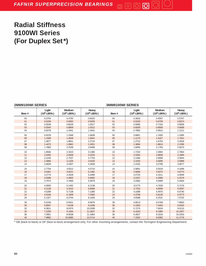
50 102800
FAFNIR SUPERPRECISION BEARINGS
2MM9100WI SERIES 3MM9100WI SERIESLight Medium Heavy Light Medium Heavy
Bore # (106 LB/IN.) (106 LB/IN.) (106 LB/IN.) Bore # (106 LB/IN.) (106 LB/IN.) (106 LB/IN.)
00 0.3754 0.4790 0.6020 00 0.3626 0.4597 0.576701 0.5209 0.6592 0.8255 01 0.5333 0.6709 0.837402 0.5539 0.8028 1.0017 02 0.5680 0.7154 0.893903 0.5540 0.8809 1.0512 03 0.6509 0.8569 0.958904 0.8278 1.0441 1.3041 04 0.7882 0.9912 1.2121
05 0.9229 1.2568 1.6608 05 0.8801 1.1930 1.439506 1.1599 1.4649 1.9641 06 1.1170 1.4427 1.755107 1.3877 1.8841 2.2724 07 1.2722 1.6754 2.091808 1.4473 1.9681 2.4551 08 1.3894 1.8814 2.228509 1.7883 2.2539 2.8499 09 1.6065 2.1765 2.6070
10 1.8566 2.3423 3.1380 10 1.7232 2.3994 2.786411 2.0492 2.6558 3.3225 11 2.0264 2.6839 3.189512 2.2246 2.7537 3.7753 12 2.1466 2.9068 3.394413 2.4856 3.1325 3.9105 13 2.2203 3.0095 3.598914 2.6839 3.4307 4.2828 14 2.4192 3.2798 3.9577
15 2.7754 3.5512 4.5710 15 2.5851 3.5019 4.169616 3.0301 3.9221 5.1481 16 2.9056 3.9372 4.677417 3.2774 4.2628 5.4399 17 3.0720 4.1611 4.959918 3.5589 4.4902 5.6092 18 3.2347 4.2995 5.257919 3.7973 4.7869 5.9979 19 3.4382 4.5999 5.4929
20 4.0905 5.1492 6.2139 20 3.5775 4.7639 5.727621 4.2128 5.3415 6.6668 21 3.7315 4.8099 6.009722 4.5288 5.7138 7.1380 22 4.1088 5.4970 6.674024 4.9166 6.1909 7.5465 24 4.3708 5.8135 6.977326 5.1327 6.4744 8.1656 26 4.6588 6.2531 7.5702
28 5.5106 6.9421 8.5876 28 4.8513 6.5769 7.896330 5.8567 7.6158 9.2186 30 5.1953 7.0453 8.502532 6.3811 8.0375 10.0299 32 5.7275 7.6534 9.011534 7.2290 9.1064 11.3637 34 6.4240 8.1980 10.240736 7.0951 8.9538 11.1864 36 6.4927 8.1819 10.226340 7.9862 10.0685 12.5714 40 7.1552 9.5082 11.4776
* DB (back-to-back) or DF (face-to-face) arrangement only; For other mounting arrangements, contact the Torrington Engineering Department.
Radial Stiffness9100WI Series(For Duplex Set*)

51102800
FAFNIR SUPERPRECISION BEARINGS
2MM9100WI SERIES 3MM9100WI SERIESX-Light to Light to Medium to X-Light to Light to Medium to
Bore # Light Medium Heavy Bore # Light Medium Heavy
(IN.) (IN.) (IN.) (IN.) (IN.) (IN.)
00 0.00005 0.00011 0.00017 00 0.00003 0.00007 0.0001101 0.00007 0.00013 0.00020 01 0.00004 0.00009 0.0001402 0.00006 0.00023 0.00024 02 0.00004 0.00015 0.0001703 0.00006 0.00031 0.00022 03 0.00004 0.00021 0.0001504 0.00014 0.00021 0.00032 04 0.00008 0.00012 0.00018
05 0.00005 0.00028 0.00044 05 0.00003 0.00015 0.0002506 0.00011 0.00025 0.00052 06 0.00005 0.00013 0.0002907 0.00016 0.00039 0.00038 07 0.00008 0.00021 0.0002108 0.00010 0.00038 0.00045 08 0.00005 0.00020 0.0002509 0.00020 0.00033 0.00052 09 0.00010 0.00017 0.00028
10 0.00017 0.00032 0.00066 10 0.00015 0.00038 0.0002711 0.00015 0.00038 0.00051 11 0.00021 0.00036 0.0003512 0.00017 0.00031 0.00077 12 0.00021 0.00040 0.0003213 0.00023 0.00039 0.00057 13 0.00017 0.00039 0.0003714 0.00030 0.00046 0.00065 14 0.00022 0.00044 0.00044
15 0.00026 0.00045 0.00073 15 0.00023 0.00045 0.0004216 0.00029 0.00051 0.00088 16 0.00029 0.00050 0.0004617 0.00033 0.00055 0.00082 17 0.00029 0.00051 0.0004818 0.00046 0.00056 0.00082 18 0.00033 0.00051 0.0005919 0.00047 0.00058 0.00086 19 0.00035 0.00054 0.00053
20 0.00050 0.00060 0.00072 20 0.00032 0.00052 0.0005421 0.00051 0.00065 0.00093 21 0.00035 0.00048 0.0006822 0.00054 0.00065 0.00095 22 0.00039 0.00060 0.0006624 0.00059 0.00069 0.00088 24 0.00040 0.00061 0.0006226 0.00067 0.00077 0.00119 26 0.00049 0.00074 0.00078
28 0.00070 0.00080 0.00111 28 0.00046 0.00076 0.0007530 0.00070 0.00098 0.00108 30 0.00049 0.00081 0.0008232 0.00082 0.00092 0.00134 32 0.00058 0.00087 0.0007734 0.00096 0.00103 0.00151 34 0.00065 0.00077 0.0011236 0.00095 0.00111 0.00162 36 0.00073 0.00080 0.0012240 0.00099 0.00124 0.00181 40 0.00080 0.00114 0.00122
* DB (back-to-back) or DF (face-to-face) arrangement only; For other mounting arrangements, contact the Torrington Engineering Department.
Spacer Offsets9100WI Series(For Duplex Set*)
SU
PE
RP
RE
CIS
ION
BE
AR
ING
S

52 102800
FAFNIR SUPERPRECISION BEARINGS
DIMENSIONS – TOLERANCES All inch tolerance in .0001 units
Bearing Outside Maximum BallNumber Bore Diameter Width Fillet Radius Complement
Tolerance Tolerance Tolerance Bearing Corner+.0000" +.0000" +.0000" will Clear **+.0µm +.0µm +.0µm
to minus to minus to minus
in. mm in. µm in. mm in. µm in. mm in. µm in. mm Qty. (Dia.)in.
MM9101K 0.4724 12 1.5 4 1.1024 28 2.0 5 0.3150 8 31 80 0.012 0.3 8 3⁄16MM9103K 0.6693 17 1.5 4 1.3780 35 2.5 6 0.3937 10 31 80 0.012 0.3 10 3⁄16MM9104K 0.7874 20 2.0 5 1.6535 42 2.5 6 0.4724 12 47 120 0.024 0.6 8 1⁄4MM9105K 0.9843 25 2.0 5 1.8504 47 2.5 6 0.4724 12 47 120 0.024 0.6 10 1⁄4MM9106K 1.1811 30 2.0 5 2.1654 55 3.0 7 0.5118 13 47 120 0.039 1.0 11 9⁄32
MM9107K 1.3780 35 2.5 6 2.4409 62 3.0 7 0.5512 14 47 120 0.039 1.0 11 5⁄16MM9108K 1.5748 40 2.5 6 2.6772 68 3.0 7 0.5906 15 47 120 0.039 1.0 12 5⁄16MM9109K 1.7717 45 2.5 6 2.9528 75 3.0 7 0.6299 16 47 120 0.039 1.0 13 11⁄ 32MM9110K 1.9685 50 2.5 6 3.1496 80 3.0 7 0.6299 16 47 120 0.039 1.0 14 11⁄ 32MM9111K 2.1654 55 3.0 7 3.5433 90 3.0 8 0.7087 18 59 150 0.039 1.0 13 13⁄ 32
MM9112K 2.3622 60 3.0 7 3.7402 95 3.0 8 0.7087 18 59 150 0.039 1.0 14 13⁄ 32MM9113K 2.5591 65 3.0 7 3.9370 100 3.0 8 0.7087 18 59 150 0.039 1.0 15 13⁄ 32MM9114K 2.7559 70 3.0 7 4.3307 110 3.0 8 0.7874 20 59 150 0.039 1.0 14 15⁄ 32
MM9115K 2.9528 75 3.0 7 4.5276 115 3.0 8 0.7874 20 59 150 0.039 1.0 15 15⁄ 32MM9116K 3.1496 80 3.0 7 4.9213 125 3.5 9 0.8661 22 59 150 0.039 1.0 14 17⁄ 32MM9117K 3.3465 85 3.0 8 5.1181 130 3.5 9 0.8661 22 79 200 0.039 1.0 15 17⁄ 32MM9118K 3.5433 90 3.0 8 5.5118 140 3.5 9 0.9449 24 79 200 0.059 1.5 14 19⁄ 32MM9120K 3.9370 100 3.0 8 5.9055 150 3.5 9 0.9449 24 79 200 0.059 1.5 15 19⁄ 32
MM9122K 4.3307 110 3.0 8 6.6929 170 4.0 10 1.1024 28 79 200 0.079 2.0 14 11⁄16MM9124K 4.7244 120 3.0 8 7.0866 180 4.0 10 1.1024 28 79 200 0.079 2.0 15 11⁄16MM9126K 5.1181 130 4.0 10 7.8740 200 4.5 11 1.2992 33 98 250 0.079 2.0 14 13⁄16
For standard, non-preloaded applications, do not exceed 350,000 dN.** ABMA std. 20 (ras max).
Extra-LightMM9100K SeriesDeep Groove ConradSuperprecision MM:Superprecision bearings are manufactured to a ABEC-7(ISO P4) tolerance class.
K Construction:This design incorporates two full shoulders on both the innerand outer rings. The complement of balls are separated by atwo-piece cage.
To specify a ceramic hybrid bearing, add “C” to the partnumber, after the prefix that specifies precision type.
D
C
d
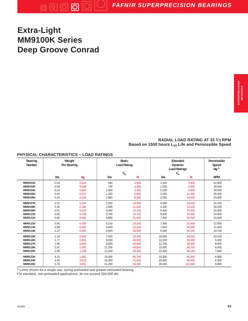
53102800
FAFNIR SUPERPRECISION BEARINGS
PHYSICAL CHARACTERISTICS – LOAD RATINGSBearing Weight Static Extended PermissibleNumber Per Bearing Load Rating Dynamic Speed
Load Ratings Ng *Co Ce
lbs kg lbs N lbs N RPM
MM9101K 0.04 0.020 540 2,400 1,320 5,900 52,800MM9103K 0.08 0.038 735 3,300 1,530 6,800 39,600MM9104K 0.14 0.064 1,000 4,400 2,200 9,800 34,000MM9105K 0.16 0.074 1,320 5,900 2,550 11,300 28,300MM9106K 0.24 0.109 1,860 8,300 3,350 14,900 23,300
MM9107K 0.32 0.144 2,320 10,300 4,050 18,000 20,700MM9108K 0.40 0.180 2,600 11,600 4,300 19,100 18,200MM9109K 0.51 0.230 3,400 15,100 5,400 24,000 16,300MM9110K 0.55 0.248 3,750 16,700 5,600 24,900 14,900MM9111K 0.80 0.362 4,800 21,400 7,200 32,000 13,500
MM9112K 0.95 0.430 5,210 23,200 7,340 32,600 12,500MM9113K 0.99 0.450 5,650 25,200 7,610 33,900 11,500MM9114K 1.37 0.620 6,940 30,900 9,490 42,200 10,700
MM9115K 1.34 0.606 7,500 33,400 10,000 44,500 10,100MM9116K 1.77 0.804 9,000 40,000 12,200 54,300 9,400MM9117K 1.86 0.845 9,650 42,900 12,700 56,500 8,900MM9118K 2.41 1.092 11,200 49,800 15,000 66,700 8,400MM9120K 2.66 1.208 12,200 54,300 15,300 68,100 7,600
MM9122K 4.15 1.882 15,000 66,700 19,300 85,800 6,800MM9124K 4.45 2.019 16,300 72,500 20,000 89,000 6,300MM9126K 6.70 3.041 21,200 94,300 26,000 115,600 5,800
* Limits shown for a single row, spring preloaded and grease lubricated bearing.For standard, non-preloaded applications, do not exceed 350,000 dN.
Extra-LightMM9100K SeriesDeep Groove Conrad
RADIAL LOAD RATING AT 33 1⁄ 3 RPMBased on 1500 hours L 10 Life and Permissible Speed
SU
PE
RP
RE
CIS
ION
BE
AR
ING
S

54 102800
FAFNIR SUPERPRECISION BEARINGS
FREQUENCY COEFFICIENTSBearing FTF BSF BPFO BPFI FTFNumber
Fundamental Train Ball Spin Ball Pass Frequency Ball Pass Frequency Fundamental TrainFrequency Frequency Outer Inner Frequency
(Inner Rotation) (Outer Rotation)
MM9101K 0.3846 2.0513 3.0769 4.9231 0.6154MM9103K 0.4082 2.6325 4.0823 5.9177 0.5918MM9104K 0.3976 2.3386 3.1807 4.8193 0.6024MM9105K 0.4118 2.7464 4.1180 5.8820 0.5882MM9106K 0.4171 2.9329 4.5881 6.4119 0.5829
MM9107K 0.4182 2.9732 4.5998 6.4002 0.5818MM9108K 0.4265 3.3281 5.1181 6.8819 0.5735MM9109K 0.4272 3.3632 5.5541 7.4459 0.5728MM9110K 0.4328 3.6550 6.0597 7.9403 0.5672MM9111K 0.4288 3.4419 5.5749 7.4251 0.5712
MM9112K 0.4334 3.6888 6.0680 7.9320 0.5666MM9113K 0.4375 3.9351 6.5619 8.4381 0.5625MM9114K 0.4339 3.7134 6.0740 7.9260 0.5661
MM9115K 0.4373 3.9268 6.5600 8.4400 0.5627MM9116K 0.4342 3.7322 6.0785 7.9215 0.5658MM9117K 0.4374 3.9288 6.5605 8.4395 0.5626MM9118K 0.4344 3.7471 6.0820 7.9180 0.5656MM9120K 0.4397 4.0839 6.5951 8.4049 0.5603
MM9122K 0.4376 3.9462 6.1269 7.8731 0.5624MM9124K 0.4418 4.2376 6.6271 8.3729 0.5582MM9126K 0.4375 3.9351 6.1245 7.8755 0.5625
Extra-LightMM9100K SeriesDeep Groove ConradSuperprecision Bearings
FTF Fundamental Train Frequency: The frequency atwhich the retainer will operate.
BSF Ball Spin Frequency: The frequency at which asingle defect on a rolling element will be detected.
BPFO Ball Pass Frequency Outer: The frequency atwhich a single defect in the outer race will bedetected.
BPFI Ball Pass Frequency Inner: The frequency atwhich a single defect in the inner race will bedetected.

55102800
FAFNIR SUPERPRECISION BEARINGS
SU
PE
RP
RE
CIS
ION
BE
AR
ING
S

56 102800
FAFNIR SUPERPRECISION BEARINGS
Light2MM200WI Series3MM200WI Series
DIMENSIONS – TOLERANCESAll inch tolerance in .0001 UnitsBearing Outside Maximum BallNumber Bore Diameter Width* Fillet Radius Complement
Nominal Tolerance Nominal Tolerance Nominal Tolerance Bearing Corner
Dimension +.0000" Dimension +.0000" Dimension +.0000" will Clear **+.0µm +.0µm +.0µm
2MM to minus to minus to minus
&3MM in. mm in. µm in. mm in. µm in. mm in. µm in. mm Qty. (Dia.)in.
200WI 0.3937 10 1.5 3.8 1.1811 30 2.0 5.1 0.3543 9 16 40 0.024 0.6 8 7 ⁄32201WI 0.4724 12 1.5 3.8 1.2598 32 2.5 6.4 0.3937 10 31 80 0.024 0.6 9 15⁄ 64202WI 0.5906 15 1.5 3.8 1.3780 35 2.5 6.4 0.4331 11 31 80 0.024 0.6 10 15 ⁄64203WI 0.6693 17 1.5 3.8 1.5748 40 2.5 6.4 0.4724 12 31 80 0.024 0.6 10 17⁄ 64204WI 0.7874 20 2.0 5.1 1.8504 47 2.5 6.4 0.5512 14 47 130 0.039 1.0 10 5⁄ 16
205WI 0.9843 25 2.0 5.1 2.0472 52 3.0 7.7 0.5906 15 47 130 0.039 1.0 12 5⁄ 16206WI 1.1811 30 2.0 5.1 2.4409 62 3.0 7.7 0.6299 16 47 130 0.039 1.0 12 3⁄ 8207WI 1.3780 35 2.5 6.4 2.8346 72 3.0 7.7 0.6693 17 47 130 0.039 1.0 12 7⁄ 16208WI 1.5748 40 2.5 6.4 3.1496 80 3.0 7.7 0.7087 18 47 130 0.039 1.0 11 1⁄ 2209WI 1.7717 45 2.5 6.4 3.3465 85 3.0 7.7 0.7480 19 47 130 0.039 1.0 13 1⁄ 2
Dd
C
Superprecision MM:Superprecision bearings are manufactured to a ABEC-7(ISO P4) tolerance class.
WI Construction:This design incorporates a low shoulder on the non-thrustside of the outer rings. The maximum complement of ballsis separated by a one-piece cage which is piloted againstthe ground land of the outer ring.
To specify a ceramic hybrid bearing, add “C” to the partnumber, after the prefix that specifies precision type.
* Refer to page E4 for width tolerance of preloaded bearings.** ABMA std. 20 (ras max).

57102800
FAFNIR SUPERPRECISION BEARINGS
C (WIDTH) X 2
d DD d D d D
C (WIDTH) X 2
C (WIDTH) X 2
WI Type Duplex Mounting Arrangements
Back-to-Back Face-to-Face TandemDB DF DT
DIMENSIONS – TOLERANCESAll inch tolerance in .0001 UnitsBearing Outside Maximum BallNumber Bore Diameter Width* Fillet Radius Complement
Nominal Tolerance Nominal Tolerance Nominal Tolerance Bearing Corner
Dimension +.0000" Dimension +.0000" Dimension +.0000" will Clear **
+.0µm +.0µm +.0µm
2MM to minus to minus to minus
&3MM in. mm in. µm in. mm in. µm in. mm in. µm in. mm Qty. (Dia.)in.
210WI 1.9685 50 2.5 6.4 3.5433 90 3.0 7.7 0.7874 20 47 130 0.039 1.0 14 1⁄ 2211WI 2.1654 55 3.0 7.7 3.9370 100 3.0 7.7 0.8268 21 59 150 0.059 1.5 14 9⁄ 16212WI 2.3622 60 3.0 7.7 4.3307 110 3.0 7.7 0.8661 22 59 150 0.059 1.5 14 5⁄ 8213WI 2.5591 65 3.0 7.7 4.7244 120 3.0 7.7 0.9055 23 59 150 0.059 1.5 14 21 ⁄32214WI 2.7559 70 3.0 7.7 4.9213 125 3.5 9.0 0.9449 24 59 150 0.059 1.5 14 11⁄ 16
215WI 2.9528 75 3.0 7.7 5.1181 130 3.5 9.0 0.9843 25 59 150 0.059 1.5 15 11⁄ 16216WI 3.1496 80 3.0 7.7 5.5118 140 3.5 9.0 1.0236 26 59 150 0.079 2.0 15 3⁄ 4217WI 3.3465 85 3.0 7.7 5.9055 150 3.5 9.0 1.1024 28 79 200 0.079 2.0 15 13⁄ 16218WI 3.5433 90 3.0 7.7 6.2992 160 4.0 10.3 1.1811 30 79 200 0.079 2.0 14 7⁄ 8219WI 3.7402 95 3.0 7.7 6.6929 170 4.0 10.3 1.2598 32 79 200 0.079 2.1 14 15⁄ 16
220WI 3.9370 100 3.0 7.7 7.0866 180 4.0 10.3 1.3386 34 79 200 0.079 2.1 14 1222WI 4.3307 110 3.0 7.7 7.8740 200 4.5 11.5 1.4961 38 79 200 0.079 2.1 14 1 1⁄ 8224WI 4.7244 120 3.0 7.7 8.4646 215 4.5 11.5 1.5748 40 79 200 0.079 2.1 14 1 3⁄ 16226WI 5.1181 130 4.0 10.3 9.0551 230 4.5 11.5 1.5748 40 98 250 0.098 2.5 17 1 3⁄ 16230WI 5.9055 150 4.0 10.3 10.6299 270 5.0 12.8 1.7717 45 98 250 0.098 2.5 15 1 1⁄ 2
* Refer to page E4 for width tolerance of preloaded bearings.** ABMA std. 20 (ras max).
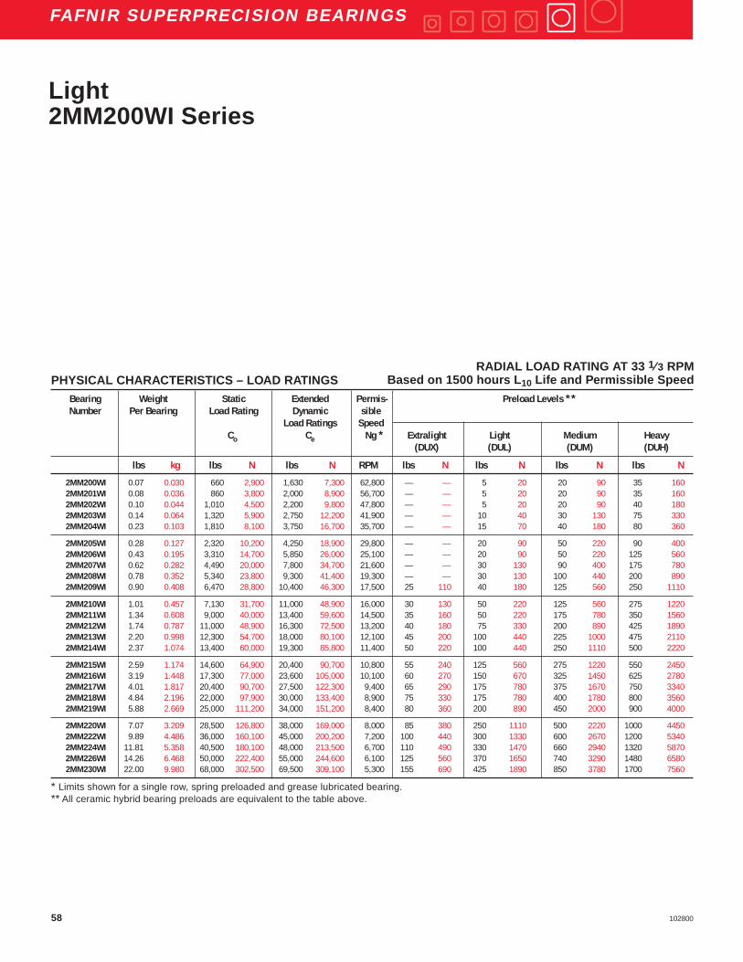
58 102800
FAFNIR SUPERPRECISION BEARINGS
PHYSICAL CHARACTERISTICS – LOAD RATINGSBearing Weight Static Extended Permis- Preload Levels **Number Per Bearing Load Rating Dynamic sible
Load Ratings SpeedCo Ce Ng * Extralight Light Medium Heavy
(DUX) (DUL) (DUM) (DUH)
lbs kg lbs N lbs N RPM lbs N lbs N lbs N lbs N
2MM200WI 0.07 0.030 660 2,900 1,630 7,300 62,800 — — 5 20 20 90 35 1602MM201WI 0.08 0.036 860 3,800 2,000 8,900 56,700 — — 5 20 20 90 35 1602MM202WI 0.10 0.044 1,010 4,500 2,200 9,800 47,800 — — 5 20 20 90 40 1802MM203WI 0.14 0.064 1,320 5,900 2,750 12,200 41,900 — — 10 40 30 130 75 3302MM204WI 0.23 0.103 1,810 8,100 3,750 16,700 35,700 — — 15 70 40 180 80 360
2MM205WI 0.28 0.127 2,320 10,200 4,250 18,900 29,800 — — 20 90 50 220 90 4002MM206WI 0.43 0.195 3,310 14,700 5,850 26,000 25,100 — — 20 90 50 220 125 5602MM207WI 0.62 0.282 4,490 20,000 7,800 34,700 21,600 — — 30 130 90 400 175 7802MM208WI 0.78 0.352 5,340 23,800 9,300 41,400 19,300 — — 30 130 100 440 200 8902MM209WI 0.90 0.408 6,470 28,800 10,400 46,300 17,500 25 110 40 180 125 560 250 1110
2MM210WI 1.01 0.457 7,130 31,700 11,000 48,900 16,000 30 130 50 220 125 560 275 12202MM211WI 1.34 0.608 9,000 40,000 13,400 59,600 14,500 35 160 50 220 175 780 350 15602MM212WI 1.74 0.787 11,000 48,900 16,300 72,500 13,200 40 180 75 330 200 890 425 18902MM213WI 2.20 0.998 12,300 54,700 18,000 80,100 12,100 45 200 100 440 225 1000 475 21102MM214WI 2.37 1.074 13,400 60,000 19,300 85,800 11,400 50 220 100 440 250 1110 500 2220
2MM215WI 2.59 1.174 14,600 64,900 20,400 90,700 10,800 55 240 125 560 275 1220 550 24502MM216WI 3.19 1.448 17,300 77,000 23,600 105,000 10,100 60 270 150 670 325 1450 625 27802MM217WI 4.01 1.817 20,400 90,700 27,500 122,300 9,400 65 290 175 780 375 1670 750 33402MM218WI 4.84 2.196 22,000 97,900 30,000 133,400 8,900 75 330 175 780 400 1780 800 35602MM219WI 5.88 2.669 25,000 111,200 34,000 151,200 8,400 80 360 200 890 450 2000 900 4000
2MM220WI 7.07 3.209 28,500 126,800 38,000 169,000 8,000 85 380 250 1110 500 2220 1000 44502MM222WI 9.89 4.486 36,000 160,100 45,000 200,200 7,200 100 440 300 1330 600 2670 1200 53402MM224WI 11.81 5.358 40,500 180,100 48,000 213,500 6,700 110 490 330 1470 660 2940 1320 58702MM226WI 14.26 6.468 50,000 222,400 55,000 244,600 6,100 125 560 370 1650 740 3290 1480 65802MM230WI 22.00 9.980 68,000 302,500 69,500 309,100 5,300 155 690 425 1890 850 3780 1700 7560
* Limits shown for a single row, spring preloaded and grease lubricated bearing.** All ceramic hybrid bearing preloads are equivalent to the table above.
Light2MM200WI Series
RADIAL LOAD RATING AT 33 1⁄ 3 RPMBased on 1500 hours L 10 Life and Permissible Speed

59102800
FAFNIR SUPERPRECISION BEARINGS
FREQUENCY COEFFICIENTS
Bearing FTF BSF BPFO BPFI FTFNumber
Fundamental Train Ball Spin Ball Pass Frequency Ball Pass Frequency Fundamental TrainFrequency Frequency Outer Inner Frequency
(Inner Rotation) (Outer Rotation)
2MM200WI 0.3668 1.6722 2.9345 5.0655 0.63322MM201WI 0.3699 1.7226 3.3290 5.6710 0.63012MM202WI 0.3855 1.9898 3.8552 6.1448 0.61452MM203WI 0.3861 2.0025 3.8609 6.1391 0.61392MM204WI 0.3857 2.0000 3.8570 6.1430 0.6143
2MM205WI 0.4008 2.3347 4.8091 7.1909 0.59922MM206WI 0.4001 2.3182 4.8007 7.1993 0.59992MM207WI 0.3997 2.3104 4.7965 7.2035 0.60032MM208WI 0.3980 2.2638 4.3777 6.6223 0.60202MM209WI 0.4058 2.4683 5.2757 7.7243 0.5942
2MM210WI 0.4126 2.6716 5.7757 8.2243 0.58742MM211WI 0.4110 2.6263 5.7543 8.2457 0.58902MM212WI 0.4098 2.5901 5.7376 8.2624 0.59022MM213WI 0.4130 2.6906 5.7818 8.2182 0.58702MM214WI 0.4135 2.7082 5.7891 8.2109 0.5865
2MM215WI 0.4177 2.8554 6.2659 8.7341 0.58232MM216WI 0.4164 2.8064 6.2462 8.7538 0.58362MM217WI 0.4152 2.7649 6.2281 8.7719 0.58482MM218WI 0.4142 2.7301 5.7984 8.2016 0.58582MM219WI 0.4132 2.6992 5.7853 8.2147 0.5868
2MM220WI 0.4125 2.6714 5.7744 8.2256 0.58752MM222WI 0.4110 2.6263 5.7543 8.2457 0.58902MM224WI 0.4131 2.6927 5.7830 8.2170 0.58692MM226WI 0.4192 2.9059 7.1260 9.8740 0.58082MM230WI 0.4124 2.6714 6.1865 8.8135 0.5876
Light2MM200WI Series
Superprecision Bearings
FTF Fundamental Train Frequency: The frequency atwhich the retainer will operate.
BSF Ball Spin Frequency: The frequency at which asingle defect on a rolling element will be detected.
BPFO Ball Pass Frequency Outer: The frequency atwhich a single defect in the outer race will bedetected.
BPFI Ball Pass Frequency Inner: The frequency atwhich a single defect in the inner race will bedetected.
SU
PE
RP
RE
CIS
ION
BE
AR
ING
S

60 102800
FAFNIR SUPERPRECISION BEARINGS
PHYSICAL CHARACTERISTICS – LOAD RATINGSBearing Weight Static Extended Permis- Preload Levels **Number Per Bearing Load Rating Dynamic sible
Load Ratings SpeedNg *
Co Ce Extralight Light Medium Heavy(DUX) (DUL) (DUM) (DUH)
lbs kg lbs N lbs N RPM lbs N lbs N lbs N lbs N
3MM200WI 0.07 0.030 640 2,800 1,600 7,100 56,500 — — 10 40 30 130 60 2703MM201WI 0.08 0.036 830 3,700 1,960 8,700 51,000 — — 10 40 30 130 60 2703MM202WI 0.10 0.044 980 4,400 2,120 9,400 43,000 — — 15 70 40 180 80 3603MM203WI 0.14 0.064 1,270 5,600 2,600 11,600 37,700 — — 20 90 75 330 100 4403MM204WI 0.23 0.103 1,730 7,700 3,550 15,800 32,100 — — 30 130 80 360 125 560
3MM205WI 0.28 0.127 2,200 9,800 4,050 18,000 26,800 — — 35 160 90 400 150 6703MM206WI 0.43 0.195 3,150 14,000 5,600 24,900 22,600 — — 50 220 125 560 200 8903MM207WI 0.62 0.282 4,300 19,100 7,350 32,700 19,400 30 130 70 310 175 780 300 13303MM208WI 0.78 0.352 5,100 22,700 9,000 40,000 17,400 35 160 80 360 200 890 300 13303MM209WI 0.90 0.408 6,200 27,600 10,000 44,500 15,800 40 180 100 440 250 1110 400 1780
3MM210WI 1.01 0.457 6,800 30,200 10,400 46,300 14,400 45 200 110 490 275 1220 450 20003MM211WI 1.34 0.608 8,650 38,500 12,900 57,400 13,100 50 220 140 620 350 1560 550 24503MM212WI 1.74 0.787 10,600 47,100 15,600 69,400 11,900 55 240 170 760 425 1890 650 28903MM213WI 2.20 0.998 11,800 52,500 17,000 75,600 10,900 60 270 190 850 475 2110 750 33403MM214WI 2.37 1.074 12,900 57,400 18,600 82,700 10,300 65 290 200 890 500 2220 800 3560
3MM215WI 2.59 1.174 14,000 62,300 19,300 85,800 9,700 80 360 220 980 550 2450 850 37803MM216WI 3.19 1.448 16,600 73,800 22,000 97,900 9,100 90 400 250 1110 625 2780 1000 44503MM217WI 4.01 1.817 19,300 85,800 26,000 115,600 8,500 100 440 270 1200 675 3000 1100 48903MM218WI 4.84 2.196 20,800 92,500 28,500 126,800 8,000 110 490 300 1330 700 3110 1250 55603MM219WI 5.88 2.669 24,000 106,800 32,000 142,300 7,600 125 560 350 1560 700 3110 1400 6230
3MM220WI 7.07 3.209 27,000 120,100 36,000 160,100 7,200 135 600 390 1730 780 3470 1560 69403MM222WI 9.89 4.486 34,500 153,500 42,500 189,000 6,500 155 690 460 2050 920 4082 1840 81803MM224WI 11.81 5.358 39,000 173,500 46,500 206,800 6,000 185 820 505 2250 1010 4480 2020 89803MM226WI 14.26 6.468 47,500 211,300 52,000 231,300 5,500 220 980 575 2560 1150 5120 2300 102303MM230WI 22.00 9.980 65,500 291,300 67,000 298,000 4,800 290 1290 700 3110 1400 6230 2800 12450
* Limits shown for a single row, spring preloaded and grease lubricated bearing.** All ceramic hybrid bearing preloads are equivalent to the table above.
Light3MM200WI Series
RADIAL LOAD RATING AT 33 1⁄ 3 RPMBased on 1500 hours L 10 Life and Permissible Speed

61102800
FAFNIR SUPERPRECISION BEARINGS
SU
PE
RP
RE
CIS
ION
BE
AR
ING
S
FREQUENCY COEFFICIENTSBearing FTF BSF BPFO BPFI FTFNumber
Fundamental Train Ball Spin Ball Pass Frequency Ball Pass Frequency Fundamental TrainFrequency Frequency Outer Inner Frequency
(Inner Rotation) (Outer Rotation)
3MM200WI 0.3668 1.6722 2.9345 5.0655 0.63323MM201WI 0.3774 1.7366 3.3966 5.6034 0.62263MM202WI 0.3921 2.0021 3.9212 6.0788 0.60793MM203WI 0.3928 2.0150 3.9277 6.0723 0.60723MM204WI 0.3929 2.0134 3.9290 6.0710 0.6071
3MM205WI 0.4070 2.3463 4.8841 7.1159 0.59303MM206WI 0.4064 2.3301 4.8769 7.1231 0.59363MM207WI 0.4061 2.3224 4.8734 7.1266 0.59393MM208WI 0.4043 2.2757 4.4476 6.5524 0.59573MM209WI 0.4117 2.4793 5.3519 7.6481 0.5883
3MM210WI 0.4180 2.6818 5.8519 8.1481 0.58203MM211WI 0.4166 2.6367 5.8323 8.1677 0.58343MM212WI 0.4155 2.6007 5.8171 8.1829 0.58453MM213WI 0.4185 2.7009 5.8587 8.1413 0.58153MM214WI 0.4189 2.7182 5.8639 8.1361 0.5811
3MM215WI 0.4228 2.8649 6.3421 8.6579 0.57723MM216WI 0.4216 2.8162 6.3241 8.6759 0.57843MM217WI 0.4205 2.7748 6.3076 8.6924 0.57953MM218WI 0.4196 2.7402 5.8738 8.1262 0.58043MM219WI 0.4187 2.7094 5.8618 8.1382 0.5813
3MM220WI 0.4179 2.6816 5.8506 8.1494 0.58213MM222WI 0.4166 2.6367 5.8323 8.1677 0.58343MM224WI 0.4184 2.7026 5.8573 8.1427 0.58163MM226WI 0.4241 2.9151 7.2100 9.7900 0.57593MM230WI 0.4179 2.6815 6.2681 8.7319 0.5821
Light3MM200WI SeriesSuperprecision Bearings
FTF Fundamental Train Frequency: The frequency atwhich the retainer will operate.
BSF Ball Spin Frequency: The frequency at which asingle defect on a rolling element will be detected.
BPFO Ball Pass Frequency Outer: The frequency atwhich a single defect in the outer race will bedetected.
BPFI Ball Pass Frequency Inner: The frequency atwhich a single defect in the inner race will bedetected.

62 102800
FAFNIR SUPERPRECISION BEARINGS
PERMISSIBLE OPERATING SPEEDS – RPM2MM & 3MM Superprecision Angular Contact Spindle Bearings
GREASE OIL
“DB” Mounting Grease Capacity Kluber Isoflex NBU 15 “DB” Mounting
15 Degree (DUL) (DUM) (DUH) 25 % 40 % 15 % 20 % (DUL) (DUM) (DUH)Contact Angle Light Medium Heavy (grams) (grams) (grams) (grams) Light Medium Heavy
2MM200WI 50,200 37,700 25,100 0.3 0.5 0.20 0.27 85,300 64,100 42,7002MM201WI 45,400 34,000 22,200 0.4 0.6 0.25 0.33 79,100 57,800 39,4002MM202WI 38,200 28,700 19,100 0.5 0.8 0.32 0.43 66,300 48,800 33,2002MM203WI 33,500 25,100 16,500 0.7 1.1 0.45 0.59 58,100 42,700 29,1002MM204WI 28,600 21,400 14,300 1.1 1.7 0.72 0.96 48,600 36,400 24,300
2MM205WI 23,800 17,900 11,900 1.3 2.1 0.88 1.18 40,500 30,400 20,2002MM206WI 20,000 15,100 10,000 2.0 3.1 1.31 1.74 34,200 25,600 17,0002MM207WI 17,300 13,000 8,600 2.7 4.4 1.82 2.43 29,400 22,000 14,6002MM208WI 15,400 11,600 7,700 3.7 6.0 2.49 3.32 26,200 19,700 13,1002MM209WI 14,000 10,500 7,000 4.2 6.6 2.77 3.70 22,800 17,900 11,900
2MM210WI 12,500 9,600 6,400 4.8 7.6 3.2 4.3 21,800 16,300 10,9002MM211WI 11,600 8,700 5,800 6.1 9.7 4.1 5.4 19,700 14,800 9,9002MM212WI 10,600 7,920 5,300 7.5 12.0 5.0 6.7 18,000 13,500 9,0002MM213WI 9,700 7,260 4,800 9.2 14.6 6.1 8.1 16,500 12,300 8,2002MM214WI 9,100 6,840 4,600 10.6 16.9 7.0 9.4 15,500 11,600 7,800
2MM215WI 8,600 6,480 4,300 11.6 18.6 7.8 10.3 14,600 11,020 7,3002MM216WI 8,100 6,060 4,000 13.7 22.0 9.2 12.2 13,800 10,300 6,8002MM217WI 7,500 5,640 3,800 16.9 27.1 11.3 15.1 12,800 9,590 6,5002MM218WI 7,100 5,340 3,600 21.5 34.4 14.4 19.1 12,100 9,080 6,1002MM219WI 6,700 5,040 3,400 25.8 41.4 17.3 23.0 11,400 8,570 5,800
2MM220WI 6,400 4,800 3,200 30.7 49.1 20.5 27.3 10,900 8,160 5,4002MM222WI 5,800 4,320 2,900 42.3 67.6 28.2 37.6 9,900 7,340 4,9002MM224WI 5,400 4,020 2,700 51.4 82.3 34.3 45.8 9,200 6,830 4,6002MM226WI 4,900 3,660 2,400 50.8 81.3 33.9 45.2 8,300 6,220 4,1002MM230WI 4,200 3,180 2,160 82.4 131.9 55.0 73.4 7,100 5,410 3,600
Notes: For 3MM (25 Degree Contact Angle) Spindle Bearings, use 90% of the Permissible Operating Speeds above.* For 2MMC and 3MMC Spindle Bearings, use 120% of the Permissible Operating Speeds.For other bearing configurations beside a back-to-back mounted duplex set, please refer to page E36 to calculate thepermissible operating speed (Sp.).
Light200WI Series

63102800
FAFNIR SUPERPRECISION BEARINGS
2MM200WI SERIES 3MM200WI SERIESBore # X-Light Light Medium Heavy Bore # Light Medium Heavy
(106 LB/IN.) (106 LB/IN.) (106 LB/IN.) (106 LB/IN.) (106 LB/IN.) (106 LB/IN.) (106 LB/IN.)
00 0.009 0.106 0.189 0.245 00 0.225 0.343 0.45601 0.091 0.110 0.195 0.252 01 0.256 0.386 0.50802 0.097 0.118 0.207 0.284 02 0.317 0.460 0.60903 0.127 0.146 0.235 0.365 03 0.365 0.606 0.68204 0.140 0.172 0.264 0.368 04 0.430 0.627 0.751
05 0.169 0.215 0.323 0.428 05 0.510 0.733 0.90206 0.190 0.219 0.323 0.498 06 0.607 0.862 1.04307 0.220 0.270 0.434 0.597 07 0.723 1.027 1.27808 0.233 0.259 0.433 0.603 08 0.758 1.074 1.26309 0.266 0.321 0.525 0.733 09 0.914 1.297 1.568
10 0.295 0.367 0.547 0.798 10 0.993 1.409 1.71911 0.310 0.362 0.626 0.879 11 1.107 1.572 1.88812 0.338 0.444 0.681 0.980 12 1.222 1.736 2.06113 0.358 0.505 0.722 1.036 13 1.290 1.832 2.20514 0.388 0.513 0.766 1.069 14 1.323 1.878 2.272
15 0.417 0.586 0.831 1.161 15 1.431 2.034 2.42516 0.444 0.647 0.910 1.245 16 1.543 2.190 2.64617 0.461 0.682 0.957 1.339 17 1.603 2.272 2.76418 0.472 0.668 0.962 1.344 18 1.636 2.257 2.84819 0.496 0.721 1.029 1.435 19 1.774 2.304 3.036
20 0.508 0.787 1.070 1.494 20 1.877 2.438 3.21122 0.564 0.880 1.192 1.657 22 2.058 2.669 3.51024 0.588 0.908 1.233 1.716 24 2.160 2.802 3.68226 0.693 1.066 1.443 2.003 26 2.562 3.319 4.35630 0.745 1.102 1.480 2.036 30 2.708 3.501 4.580
* DB (back-to-back) or DF (face-to-face) arrangement only; For other mounting arrangements, contact the Torrington Engineering Department.
Axial Stiffness200WI Series(For Duplex Set*)
SU
PE
RP
RE
CIS
ION
BE
AR
ING
S
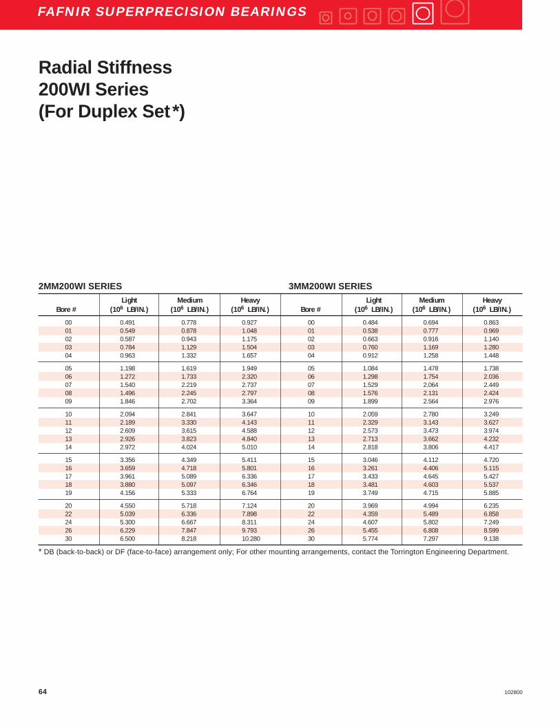
64 102800
FAFNIR SUPERPRECISION BEARINGS
2MM200WI SERIES 3MM200WI SERIESLight Medium Heavy Light Medium Heavy
Bore # (106 LB/IN.) (106 LB/IN.) (106 LB/IN.) Bore # (106 LB/IN.) (106 LB/IN.) (106 LB/IN.)
00 0.491 0.778 0.927 00 0.484 0.694 0.86301 0.549 0.878 1.048 01 0.538 0.777 0.96902 0.587 0.943 1.175 02 0.663 0.916 1.14003 0.784 1.129 1.504 03 0.760 1.169 1.28004 0.963 1.332 1.657 04 0.912 1.258 1.448
05 1.198 1.619 1.949 05 1.084 1.478 1.73806 1.272 1.733 2.320 06 1.298 1.754 2.03607 1.540 2.219 2.737 07 1.529 2.064 2.44908 1.496 2.245 2.797 08 1.576 2.131 2.42409 1.846 2.702 3.364 09 1.899 2.564 2.976
10 2.094 2.841 3.647 10 2.059 2.780 3.24911 2.189 3.330 4.143 11 2.329 3.143 3.62712 2.609 3.615 4.588 12 2.573 3.473 3.97413 2.926 3.823 4.840 13 2.713 3.662 4.23214 2.972 4.024 5.010 14 2.818 3.806 4.417
15 3.356 4.349 5.411 15 3.046 4.112 4.72016 3.659 4.718 5.801 16 3.261 4.406 5.11517 3.961 5.089 6.336 17 3.433 4.645 5.42718 3.880 5.097 6.346 18 3.481 4.603 5.53719 4.156 5.333 6.764 19 3.749 4.715 5.885
20 4.550 5.718 7.124 20 3.969 4.994 6.23522 5.039 6.336 7.898 22 4.359 5.489 6.85824 5.300 6.667 8.311 24 4.607 5.802 7.24926 6.229 7.847 9.793 26 5.455 6.808 8.59930 6.500 8.218 10.280 30 5.774 7.297 9.138
* DB (back-to-back) or DF (face-to-face) arrangement only; For other mounting arrangements, contact the Torrington Engineering Department.
Radial Stiffness200WI Series(For Duplex Set*)
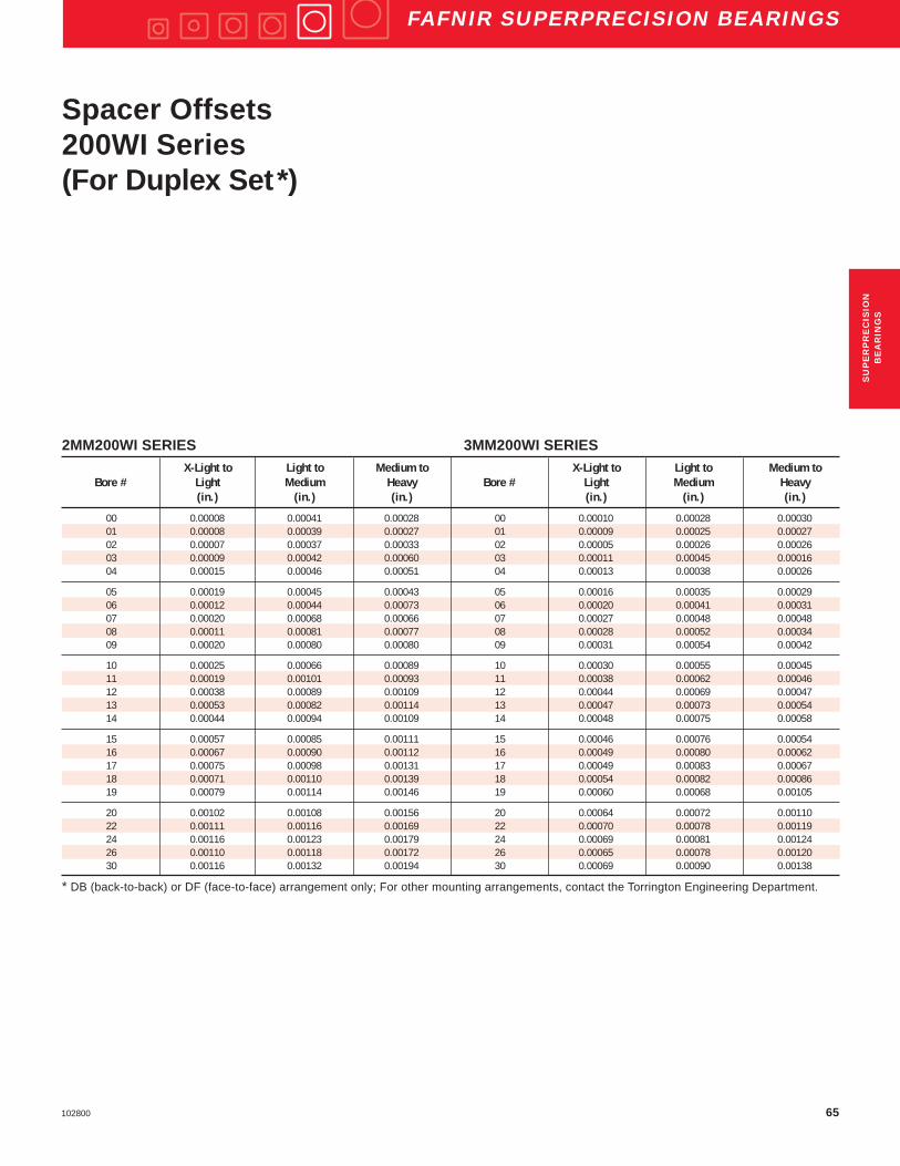
65102800
FAFNIR SUPERPRECISION BEARINGS
2MM200WI SERIES 3MM200WI SERIESX-Light to Light to Medium to X-Light to Light to Medium to
Bore # Light Medium Heavy Bore # Light Medium Heavy(in.) (in.) (in.) (in.) (in.) (in.)
00 0.00008 0.00041 0.00028 00 0.00010 0.00028 0.0003001 0.00008 0.00039 0.00027 01 0.00009 0.00025 0.0002702 0.00007 0.00037 0.00033 02 0.00005 0.00026 0.0002603 0.00009 0.00042 0.00060 03 0.00011 0.00045 0.0001604 0.00015 0.00046 0.00051 04 0.00013 0.00038 0.00026
05 0.00019 0.00045 0.00043 05 0.00016 0.00035 0.0002906 0.00012 0.00044 0.00073 06 0.00020 0.00041 0.0003107 0.00020 0.00068 0.00066 07 0.00027 0.00048 0.0004808 0.00011 0.00081 0.00077 08 0.00028 0.00052 0.0003409 0.00020 0.00080 0.00080 09 0.00031 0.00054 0.00042
10 0.00025 0.00066 0.00089 10 0.00030 0.00055 0.0004511 0.00019 0.00101 0.00093 11 0.00038 0.00062 0.0004612 0.00038 0.00089 0.00109 12 0.00044 0.00069 0.0004713 0.00053 0.00082 0.00114 13 0.00047 0.00073 0.0005414 0.00044 0.00094 0.00109 14 0.00048 0.00075 0.00058
15 0.00057 0.00085 0.00111 15 0.00046 0.00076 0.0005416 0.00067 0.00090 0.00112 16 0.00049 0.00080 0.0006217 0.00075 0.00098 0.00131 17 0.00049 0.00083 0.0006718 0.00071 0.00110 0.00139 18 0.00054 0.00082 0.0008619 0.00079 0.00114 0.00146 19 0.00060 0.00068 0.00105
20 0.00102 0.00108 0.00156 20 0.00064 0.00072 0.0011022 0.00111 0.00116 0.00169 22 0.00070 0.00078 0.0011924 0.00116 0.00123 0.00179 24 0.00069 0.00081 0.0012426 0.00110 0.00118 0.00172 26 0.00065 0.00078 0.0012030 0.00116 0.00132 0.00194 30 0.00069 0.00090 0.00138
* DB (back-to-back) or DF (face-to-face) arrangement only; For other mounting arrangements, contact the Torrington Engineering Department.
Spacer Offsets200WI Series(For Duplex Set*)
SU
PE
RP
RE
CIS
ION
BE
AR
ING
S

66 102800
FAFNIR SUPERPRECISION BEARINGS
DIMENSIONS – TOLERANCESAll inch tolerance in .0001 unitsBearing Outside Maximum BallNumber Bore Diameter Width Fillet Radius Complement
Nominal Tolerance Nominal Tolerance Nominal Tolerance Bearing Corner
Dimension +.0000" Dimension +.0000" Dimension +.0000" will Clear **
+.0µm +.0µm +.0µmto minus to minus to minus
in. mm in. µm in. mm in. µm in. mm in. µm in. mm Qty. (Dia.)in.
MM201K 0.4724 12 1.5 4 1.2598 32 2.5 6 0.0394 10 31 80 0.024 0.6 7 15⁄64MM202K 0.5906 15 1.5 4 1.3780 35 2.5 6 0.4331 11 31 80 0.024 0.6 8 15⁄64MM203K 0.6693 17 1.5 4 1.5748 40 2.5 6 0.4724 12 31 80 0.024 0.6 8 17⁄64MM204K 0.7874 20 2.0 5 1.8504 47 2.5 6 0.5512 14 47 130 0.039 1.0 8 5⁄16MM205K 0.9843 25 2.0 5 2.0472 52 3.0 7 0.5906 15 47 130 0.039 1.0 9 5⁄16
MM206K 1.1811 30 2.0 5 2.4409 62 3.0 7 0.6299 16 47 130 0.039 1.0 9 3⁄8MM207K 1.3780 35 2.5 6 2.8346 72 3.0 7 0.6693 17 47 130 0.039 1.0 9 7⁄16MM208K 1.5748 40 2.5 6 3.1496 80 3.0 7 0.7087 18 47 130 0.039 1.0 9 1⁄2MM209K 1.7717 45 2.5 6 3.3465 85 3.0 8 0.7480 19 47 130 0.039 1.0 9 1⁄2MM210K 1.9685 50 2.5 6 3.5433 90 3.0 8 0.7874 20 47 130 0.039 1.0 10 1⁄2
MM211K 2.1654 55 3.0 7 3.9370 100 3.0 8 0.8268 21 59 150 0.059 1.5 10 9⁄16MM212K 2.3622 60 3.0 7 4.3307 110 3.0 8 0.8661 22 59 150 0.059 1.5 10 5⁄8MM213K 2.5591 65 3.0 7 4.7244 120 3.0 8 0.9055 23 59 150 0.059 1.5 10 21⁄32MM214K 2.7559 70 3.0 7 4.9213 125 3.5 9 0.9449 24 59 150 0.059 1.5 10 11⁄16MM215K 2.9528 75 3.0 7 5.1181 130 3.5 9 0.9843 25 59 150 0.059 1.5 10 11⁄16
MM216K 3.1496 80 3.0 7 5.5118 140 3.5 9 1.0236 26 59 150 0.079 2.0 10 3⁄4
** ABMA std. 20 (ras max).
LightMM200K SeriesDeep Groove Conrad
D
C
d
Superprecision MM:Superprecision bearings are manufactured to a ABEC-7(ISO P4) tolerance class.
K Construction:This design incorporates two full shoulders on both theinner and outer rings. The complement of balls areseparated by a two-piece cage.
To specify a ceramic hybrid bearing, add “C” to the partnumber, after the prefix that specifies precision type.

67102800
FAFNIR SUPERPRECISION BEARINGS
PHYSICAL CHARACTERISTICS – LOAD RATINGSBearing Weight Static Extended PermissibleNumber Per Bearing Load Rating Dynamic Speed
Load Ratings Ng *
Co Ce
lbs kg lbs N lbs N RPM
MM201K 0.08 0.035 680 3,000 1,730 7,700 52,200MM202K 0.09 0.043 830 3,700 1,930 8,600 44,000MM203K 0.14 0.062 1,060 4,700 2,450 10,900 38,500MM204K 0.22 0.100 1,460 6,500 3,250 14,500 32,800MM205K 0.27 0.122 1,760 7,800 3,600 16,000 27,400
MM206K 0.41 0.185 2,550 11,300 5,000 22,200 23,000MM207K 0.59 0.267 3,450 15,300 6,550 29,100 19,800MM208K 0.74 0.337 4,500 20,000 8,300 36,900 17,700MM209K 0.83 0.377 4,550 20,200 8,300 36,900 16,000MM210K 0.94 0.425 5,200 23,100 9,000 40,000 14,600
MM211K 1.24 0.564 6,550 29,100 11,000 48,900 13,300MM212K 1.60 0.727 8,150 36,300 13,400 59,600 12,100MM213K 2.05 0.928 9,000 40,000 14,600 64,900 11,100MM214K 2.19 0.994 9,800 43,600 16,000 71,200 10,500MM215K 2.37 1.074 10,000 44,500 16,000 71,200 9,900
MM216K 2.90 1.317 12,000 53,400 18,600 82,700 9,200
* Limits shown for a single row, spring preloaded and grease lubricated bearing.For standard, non-preloaded applications, do not exceed 350,000 dN.
LightMM200K SeriesDeep Groove Conrad
SU
PE
RP
RE
CIS
ION
BE
AR
ING
S

68 102800
FAFNIR SUPERPRECISION BEARINGS
FREQUENCY COEFFICIENTS Bearing FTF BSF BPFO BPFI FTFNumber
Fundamental Train Ball Spin Ball Pass Frequency Ball Pass Frequency Fundamental TrainFrequency Frequency Outer Inner Frequency
(Inner Rotation) (Outer Rotation)
MM201K 0.3647 1.7124 2.5529 4.4471 0.6353MM202K 0.3809 1.9808 3.0475 4.9525 0.6191MM203K 0.3816 1.9937 3.0531 4.9469 0.6184MM204K 0.3815 1.9918 3.0522 4.9478 0.6185MM205K 0.3971 2.3275 3.5742 5.4258 0.6029
MM206K 0.3965 2.3111 3.5682 5.4318 0.6035MM207K 0.3961 2.3034 3.5653 5.4347 0.6039MM208K 0.3942 2.2564 3.5475 5.4525 0.6058MM209K 0.4023 2.4614 3.6208 5.3792 0.5977MM210K 0.4093 2.6652 4.0929 5.9071 0.5907
MM211K 0.4078 2.6200 4.0782 5.9218 0.5922MM212K 0.4066 2.5837 4.0662 5.9338 0.5934MM213K 0.4099 2.6846 4.0990 5.9010 0.5901MM214K 0.4104 2.7022 4.1045 5.8955 0.5896MM215K 0.4148 2.8497 4.1482 5.8518 0.5852
MM216K 0.4134 2.8005 4.1341 5.8659 0.5866
LightMM200K SeriesDeep Groove ConradSuperprecision Bearings
FTF Fundamental Train Frequency: The frequency atwhich the retainer will operate.
BSF Ball Spin Frequency: The frequency at which asingle defect on a rolling element will be detected.
BPFO Ball Pass Frequency Outer: The frequency atwhich a single defect in the outer race will bedetected.
BPFI Ball Pass Frequency Inner: The frequency atwhich a single defect in the inner race will bedetected.

69102800
FAFNIR SUPERPRECISION BEARINGS
DIMENSIONS – TOLERANCESAll inch tolerance in .0001 unitsBearing Outside Maximum BallNumber Bore Diameter Width * Fillet Radius Complement
Tolerance Tolerance Tolerance Bearing Corner
Nominal +.0000" Nominal +.0000" Nominal +.0000" will Clear **
Dimension +.0µm Dimension +.0µm Dimension +.0µmto minus to minus to minus
2MM &3MM in. mm in. µm in. mm in. µm in. mm in. µm in. mm Qty. (Dia.)in.
301WI 0.4724 12 1.5 4 1.4567 37 2.5 6 0.4724 12 31 80 0.039 1.0 8 9⁄32302WI 0.5906 15 1.5 4 1.6535 42 2.5 6 0.5118 13 31 80 0.039 1.0 10 17⁄64303WI 0.6693 17 1.5 4 1.8504 47 2.5 6 0.5512 14 31 80 0.039 1.0 7 3⁄8304WI 0.7874 20 2.0 5 2.0472 52 3.0 7 0.5906 15 47 120 0.039 1.0 8 13⁄ 32305WI 0.9843 25 2.0 5 2.4409 62 3.0 7 0.6693 17 47 120 0.039 1.0 9 15⁄ 32
306WI 1.1811 30 2.0 5 2.8346 72 3.0 7 0.7480 19 47 120 0.039 1.0 9 17⁄ 32307WI 1.3780 35 2.5 6 3.1496 80 3.0 7 0.8268 21 47 120 0.059 1.5 10 9⁄ 16308WI 1.5748 40 2.5 6 3.5433 90 3.0 8 0.9055 23 47 120 0.059 1.5 10 5⁄ 8309WI 1.7717 45 2.5 6 3.9370 100 3.0 8 0.9843 25 47 120 0.059 1.5 10 11⁄ 16310WI 1.9685 50 2.5 6 4.3307 110 3.0 8 1.0630 27 47 120 0.079 2.0 10 3⁄4
311WI 2.1654 55 3.0 7 4.7244 120 3.0 8 1.1417 29 59 150 0.079 2.0 10 13⁄ 16312WI 2.3622 60 3.0 7 5.1181 130 3.5 9 1.2205 31 59 150 0.079 2.0 10 7⁄ 8313WI 2.5591 65 3.0 7 5.5118 140 3.5 9 1.2992 33 59 150 0.079 2.0 11 15⁄ 16314WI 2.7559 70 3.0 7 5.9055 150 3.5 9 1.3780 35 59 150 0.079 2.0 11 1319WI 3.7402 95 3.0 7 7.8740 200 4.0 10 1.7717 45 79 200 0.118 3.0 10 1 3⁄ 8
* Refer to page E4 for width tolerance of preloaded bearings.** ABMA std. 20 (ras max).
Medium2MM300WI Series3MM300WI Series
Dd
C
C
Superprecision MM:Superprecision bearings are manufactured to a ABEC-7(ISO P4) tolerance class.
WI Construction:This design incorporates a low shoulder on the non-thrustside of the outer rings. The maximum complement of ballsis separated by a one-piece cage which is piloted againstthe ground land of the outer ring.
To specify a ceramic hybrid bearing, add “C” to the partnumber, after the prefix that specifies precision type.
SU
PE
RP
RE
CIS
ION
BE
AR
ING
S

70 102800
FAFNIR SUPERPRECISION BEARINGS
PHYSICAL CHARACTERISTICS – LOAD RATINGSBearing Weight Static Extended Permis- Preload Levels **Number Per Bearing Load Rating Dynamic sible
Load Ratings SpeedNg *
Co Ce Extralight Light Medium Heavy(DUX) (DUL) (DUM) (DUH)
lbs kg lbs N lbs N RPM lbs N lbs N lbs N lbs N
2MM301WI 0.13 0.061 1,060 4,700 2,550 11,300 47,600 — — 5 20 15 70 40 1802MM302WI 0.19 0.087 1,320 5,900 2,750 12,200 38,100 — — 10 40 25 110 50 2202MM303WI 0.23 0.104 1,630 7,300 3,900 17,300 36,800 — — 15 70 35 160 70 3102MM304WI 0.30 0.137 2,200 9,800 5,000 22,200 32,200 — — 20 90 50 220 90 4002MM305WI 0.49 0.221 3,450 15,300 6,950 30,900 26,200 — — 35 160 75 330 140 620
2MM306WI 0.72 0.328 4,500 20,000 8,800 39,100 22,100 — — 40 180 100 440 175 7802MM307WI 0.98 0.443 5,700 25,400 10,600 47,100 19,200 — — 50 220 125 560 225 10002MM308WI 1.34 0.608 7,200 32,000 12,900 57,400 16,900 — — 65 290 150 670 275 12202MM309WI 1.78 0.809 8,650 38,500 15,300 68,100 15,100 — — 75 330 175 780 350 15602MM310WI 2.31 1.046 10,400 46,300 18,000 80,100 13,600 — — 100 440 225 1000 400 1780
2MM311WI 2.94 1.332 12,200 54,300 20,800 92,500 12,400 — — 125 560 250 1110 475 21102MM312WI 3.67 1.665 14,300 63,600 23,600 105,000 11,400 — — 125 560 300 1330 550 24502MM313WI 4.63 2.101 18,000 80,100 28,500 126,800 10,500 — — 150 670 375 1670 675 30002MM314WI 5.62 2.548 20,800 92,500 32,000 142,300 9,800 — — 175 780 425 1890 775 34502MM319WI 12.32 5.587 35,500 157,900 47,500 211,300 7,400 — — 300 1330 700 3110 1400 6230
* Limits shown for a single row, spring preloaded and grease lubricated bearing.** All ceramic hybrid bearing preloads are equivalent to the table above.
Medium2MM300WI Series
RADIAL LOAD RATING AT 33 1⁄ 3 RPMBased on 1500 hours L 10 Life and Permissible Speed

71102800
FAFNIR SUPERPRECISION BEARINGS
FREQUENCY COEFFICIENTSBearing Number FTF BSF BPFO BPFI FTF
Fundamental Train Ball Spin Ball Pass Frequency Ball Pass Frequency Fundamental TrainFrequency Frequency Outer Inner Frequency
(Inner Rotation) (Outer Rotation)
2MM301WI 0.3594 1.5791 2.8751 5.1249 0.64062MM302WI 0.3861 2.0024 3.8609 6.1391 0.61392MM303WI 0.3564 1.5411 2.4946 4.5054 0.64362MM304WI 0.3618 1.6111 2.8941 5.1059 0.63822MM305WI 0.3681 1.6997 3.3127 5.6873 0.6319
2MM306WI 0.3724 1.7666 3.3514 5.6486 0.62762MM307WI 0.3799 1.8962 3.7990 6.2010 0.62012MM308WI 0.3820 1.9332 3.8203 6.1797 0.61802MM309WI 0.3837 1.9636 3.8373 6.1627 0.61632MM310WI 0.3851 1.9889 3.8510 6.1490 0.6149
2MM311WI 0.3861 2.0099 3.8606 6.1394 0.61392MM312WI 0.3870 2.0281 3.8704 6.1296 0.61302MM313WI 0.3879 2.0440 4.2665 6.7335 0.61212MM314WI 0.3884 2.0576 4.2729 6.7271 0.61162MM319WI 0.3857 2.0013 3.8570 6.1430 0.6143
Medium2MM300WI SeriesSuperprecision Bearings
FTF Fundamental Train Frequency: The frequency atwhich the retainer will operate.
BSF Ball Spin Frequency: The frequency at which asingle defect on a rolling element will be detected.
BPFO Ball Pass Frequency Outer: The frequency atwhich a single defect in the outer race will bedetected.
BPFI Ball Pass Frequency Inner: The frequency atwhich a single defect in the inner race will bedetected.
SU
PE
RP
RE
CIS
ION
BE
AR
ING
S

72 102800
FAFNIR SUPERPRECISION BEARINGS
PHYSICAL CHARACTERISTICS - LOAD RATINGSBearing Weight Static Extended Permis- Preload Levels **Number Per Bearing Load Rating Dynamic sible
Load Ratings SpeedCo Ce Ng * Extralight Light Medium Heavy
(DUX) (DUL) (DUM) (DUH)
lbs kg lbs N lbs N RPM lbs N lbs N lbs N lbs N
3MM301WI 0.13 0.061 1,040 4,600 2,450 10,900 42,800 — — 20 90 40 180 70 3103MM302WI 0.19 0.087 1,270 5,600 2,600 11,600 34,300 — — 20 90 40 180 80 3603MM303WI 0.23 0.104 1,600 7,100 3,800 16,900 33,100 — — 25 110 60 270 100 4403MM304WI 0.30 0.137 2,160 9,600 4,800 21,400 29,000 — — 35 160 80 360 140 6203MM305WI 0.49 0.221 3,350 14,900 6,800 30,200 23,600 — — 50 220 120 530 200 890
3MM306WI 0.72 0.328 4,300 19,100 8,500 37,800 19,900 — — 60 270 150 670 250 11103MM307WI 0.98 0.443 5,600 24,900 10,200 45,400 17,300 — — 80 360 190 850 350 15603MM308WI 1.34 0.608 6,950 30,900 12,500 55,600 15,200 — — 100 440 250 1110 400 17803MM309WI 1.78 0.808 8,500 37,800 14,600 64,900 13,600 — — 120 530 300 1330 500 22203MM310WI 2.30 1.045 10,000 44,500 17,300 77,000 12,200 — — 140 620 350 1560 600 2670
3MM311WI 2.93 1.331 11,800 52,500 20,000 89,000 11,200 — — 175 780 400 1780 700 31103MM312WI 3.67 1.663 13,700 60,900 22,800 101,400 10,300 — — 200 890 450 2000 800 35603MM313WI 4.63 2.099 17,300 77,000 27,500 122,300 9,500 — — 250 1110 600 2670 1000 44503MM314WI 5.61 2.546 20,000 89,000 31,000 137,900 8,800 — — 275 1220 650 2890 1150 51203MM319WI 12.30 5.581 34,000 151,200 45,500 202,400 6,700 — — 475 2110 1100 4890 2000 8900
* Limits shown for a single row, spring preloaded and grease lubricated bearing.** All ceramic hybrid bearing preloads are equivalent to the table above.
Medium3MM300WI Series
RADIAL LOAD RATING AT 33 1⁄ 3 RPMBased on 1500 hours L 10 Life and Permissible Speed

73102800
FAFNIR SUPERPRECISION BEARINGS
FREQUENCY COEFFICIENTSBearing FTF BSF BPFO BPFI FTFNumber
Fundamental Train Ball Spin Ball Pass Frequency Ball Pass Frequency Fundamental TrainFrequency Frequency Outer Inner Frequency
(Inner Rotation) (Outer Rotation)
3MM301WI 0.3678 1.5949 2.9425 5.0575 0.63223MM302WI 0.3928 2.0149 3.9277 6.0723 0.60723MM303WI 0.3653 1.5578 2.5571 4.4429 0.63473MM304WI 0.3701 1.6268 2.9611 5.0389 0.62993MM305WI 0.3761 1.7147 3.3850 5.6150 0.6239
3MM306WI 0.3802 1.7812 3.4214 5.5786 0.61983MM307WI 0.3874 1.9101 3.8736 6.1264 0.61263MM308WI 0.3894 1.9470 3.8936 6.1064 0.61063MM309WI 0.3910 1.9772 3.9096 6.0904 0.60903MM310WI 0.3920 2.0019 3.9205 6.0795 0.6080
3MM311WI 0.3931 2.0231 3.9314 6.0686 0.60693MM312WI 0.3941 2.0412 3.9405 6.0595 0.60593MM313WI 0.3947 2.0567 4.3415 6.6585 0.60533MM314WI 0.3954 2.0705 4.3491 6.6509 0.60463MM319WI 0.3927 2.0144 3.9270 6.0730 0.6073
Medium3MM300WI Series
Superprecision Bearings
FTF Fundamental Train Frequency: The frequency atwhich the retainer will operate.
BSF Ball Spin Frequency: The frequency at which asingle defect on a rolling element will be detected.
BPFO Ball Pass Frequency Outer: The frequency atwhich a single defect in the outer race will bedetected.
BPFI Ball Pass Frequency Inner: The frequency atwhich a single defect in the inner race will bedetected.
SU
PE
RP
RE
CIS
ION
BE
AR
ING
S

74 102800
FAFNIR SUPERPRECISION BEARINGS
PERMISSIBLE OPERATING SPEEDS – RPM2MM & 3MM Superprecision Angular Contact Spindle Bearings
GREASE OIL
“DB” Mounting Grease Capacity Kluber Isoflex NBU 15 “DB” Mounting15 Degree (DUL) (DUM) (DUH) 25 % 40 % 15 % 20 % (DUL) (DUM) (DUH)
Contact Angle Light Medium Heavy (grams) (grams) (grams) (grams) Light Medium Heavy
2MM301WI 35,700 28,600 19,000 0.6 1.0 0.40 0.53 60,700 48,600 32,4002MM302WI 28,600 22,900 15,200 0.7 1.2 0.49 0.65 48,600 38,900 25,9002MM303WI 27,600 22,100 14,700 1.2 2.0 0.83 1.10 46,900 37,500 25,0002MM304WI 24,200 19,300 12,900 1.5 2.5 1.03 1.38 41,100 32,800 21,9002MM305WI 19,700 15,700 10,500 2.3 3.8 1.57 2.09 33,400 26,700 17,800
2MM306WI 16,600 13,300 8,800 3.5 5.6 2.35 3.14 28,200 22,500 15,0002MM307WI 14,400 11,500 7,700 4.6 7.4 3.07 4.10 24,500 19,600 13,1002MM308WI 12,700 10,100 6,800 6.4 10.2 4.25 5.66 21,500 17,200 11,5002MM309WI 11,300 9,100 6,000 8.5 13.6 5.68 7.58 19,300 15,400 10,3002MM310WI 10,200 8,200 5,400 11.1 17.8 7.4 9.9 17,300 13,900 9,200
2MM311WI 9,300 7,400 5,000 14.2 22.7 9.5 12.6 15,800 12,600 8,4002MM312WI 8,600 6,800 4,600 17.7 28.3 11.8 15.8 14,500 11,600 7,8002MM313WI 7,900 6,300 4,200 20.7 33.2 13.8 18.5 13,400 10,700 7,1002MM314WI 7,400 5,900 3,900 25.2 40.3 16.8 22.4 12,500 10,000 6,7002MM319WI 5,600 4,400 3,000 60.9 97.4 40.6 54.1 9,400 7,500 5,000
Notes: For 3MM (25 Degree Contact Angle) Spindle Bearings, use 90% of the Permissible Operating Speeds above.* For 2MMC and 3MMC Spindle Bearings, use 120% of the Permissible Operating Speeds.For other bearing configurations beside a back-to-back mounted duplex set, please refer to page E36 to calculate thepermissible operating speed (Sp.).
Medium300WI Series

75102800
FAFNIR SUPERPRECISION BEARINGS
2MM300WI SERIES 3MM300WI SERIESBore # Light Medium Heavy Bore # Light Medium Heavy
(106 LB/IN.) (106 LB/IN.) (106 LB/IN.) (106 LB/IN.) (106 LB/IN.) (106 LB/IN.)
00 — — — 00 — — —01 0.100 0.159 0.253 01 0.335 0.438 0.55102 0.157 0.234 0.327 02 0.380 0.496 0.65803 0.152 0.222 0.312 03 0.364 0.509 0.62604 0.189 0.285 0.380 04 0.453 0.623 0.782
05 0.264 0.373 0.506 05 0.581 0.813 1.00006 0.283 0.427 0.563 06 0.642 0.911 1.12107 0.320 0.487 0.654 07 0.771 1.074 1.37808 0.370 0.541 0.731 08 0.860 1.224 1.48209 0.401 0.589 0.830 09 0.949 1.349 1.661
10 0.464 0.671 0.892 10 1.022 1.453 1.81011 0.504 0.694 0.956 11 1.133 1.557 1.95612 0.513 0.765 1.034 12 1.220 1.665 2.10313 0.596 0.903 1.208 13 1.425 1.995 2.45614 0.634 0.951 1.282 14 1.501 2.087 2.632
15 — — — 15 — — —16 — — — 16 — — —17 — — — 17 — — —18 — — — 18 — — —19 0.803 1.178 1.660 19 1.880 2.593 3.306
* DB (back-to-back) or DF (face-to-face) arrangement only;For other mounting arrangements, contact the TorringtonEngineering Department.
Axial Stiffness300WI Series(For Duplex Set*)
SU
PE
RP
RE
CIS
ION
BE
AR
ING
S

76 102800
FAFNIR SUPERPRECISION BEARINGS
2MM300WI SERIES 3MM300WI SERIESLight Medium Heavy Light Medium Heavy
Bore # (106 LB/IN.) (106 LB/IN.) (106 LB/IN.) Bore # (106 LB/IN.) (106 LB/IN.) (106 LB/IN.)
01 0.565 0.878 1.048 01 0.538 0.777 0.96902 0.819 0.943 1.175 02 0.663 0.916 1.14003 0.843 1.129 1.504 03 0.760 1.169 1.28004 1.039 1.332 1.657 04 0.912 1.258 1.448
05 1.417 1.619 1.949 05 1.084 1.478 1.73806 1.551 1.733 2.320 06 1.298 1.754 2.03607 1.852 2.219 2.737 07 1.529 2.064 2.44908 2.085 2.245 2.797 08 1.576 2.131 2.42409 2.248 2.702 3.364 09 1.899 2.564 2.976
10 2.094 2.841 3.647 10 2.059 2.780 3.24911 2.189 3.330 4.143 11 2.329 3.143 3.62712 2.609 3.615 4.588 12 2.573 3.473 3.97413 2.926 3.823 4.840 13 2.713 3.662 4.23214 2.972 4.024 5.010 14 2.818 3.806 4.417
15 3.356 4.349 5.411 15 3.046 4.112 4.72016 3.659 4.718 5.801 16 3.262 4.406 5.11517 3.961 5.089 6.336 17 3.433 4.645 5.42718 3.880 5.097 6.346 18 3.481 4.603 5.53719 4.156 5.333 6.764 19 3.749 4.715 5.885
Radial Stiffness300WI Series(For Duplex Set*)
* DB (back-to-back) or DF (face-to-face) arrangement only;For other mounting arrangements, contact the TorringtonEngineering Department.

77102800
FAFNIR SUPERPRECISION BEARINGS
2MM300WI SERIES 3MM300WI SERIESBore # Light to Medium to Bore # Light to Medium to
Medium Heavy Medium Heavy
(in.) (in.) (in.) (in.)
00 — — 00 — —01 0.00031 0.00049 01 0.00021 0.0002402 0.00031 0.00036 02 0.00018 0.0002803 0.00043 0.00053 03 0.00032 0.0002804 0.00051 0.00480 04 0.00033 0.00034
05 0.00050 0.00059 05 0.00040 0.0003506 0.00068 0.00061 06 0.00046 0.0003907 0.00074 0.00070 07 0.00048 0.0005208 0.00075 0.00079 08 0.00057 0.0004409 0.00081 0.00099 09 0.00062 0.00053
10 0.00088 0.00090 10 0.00068 0.0006111 0.00084 0.00109 11 0.00067 0.0006812 0.00110 0.00111 12 0.00069 0.0007413 0.00120 0.00114 13 0.00082 0.0007214 0.00127 0.00126 14 0.00083 0.00085
15 — — 15 — —16 — — 16 — —17 — — 17 — —18 — — 18 — —19 0.00040 0.00059 19 0.00111 0.00122
* DB (back-to-back) or DF (face-to-face) arrangement only;For other mounting arrangements, contact the TorringtonEngineering Department.
Spacer Offsets300WI Series(For Duplex Set*)
SU
PE
RP
RE
CIS
ION
BE
AR
ING
S

78 102800
FAFNIR SUPERPRECISION BEARINGS
Bearing Outside Maximum BallNumber Bore Diameter Width Fillet Radius Complement
Tolerance Tolerance Tolerance Bearing Corner+.0000" +.0000" +.0000" will Clear **+.0µm +.0µm +.0µm
to minus to minus to minus
in. mm in. µm in. mm in. µm in. mm in. µm in. mm Qty. (Dia.)in.
MM305K-CR 0.9843 25 2.0 5 2.4409 62 3.0 7 0.6693 17 47 130 0.039 1 7 15⁄32
MM306K-CR 1.1811 30 2.0 5 2.8346 72 3.0 7 0.7480 19 47 130 0.039 1 7 17⁄32
MM307K-CR 1.378 35 2.5 6 3.1496 80 3.0 7 0.8268 21 47 130 0.059 1.5 7 9⁄16
MM308K-CR 1.5748 40 2.5 6 3.5433 90 3.0 8 0.9055 23 47 130 0.059 1.5 8 5⁄8
MM309K-CR 1.7717 45 2.5 6 3.9370 100 3.0 8 0.9843 25 47 130 0.059 1.5 8 11⁄16
MM310K-CR 1.9685 50 2.5 6 4.3307 110 3.0 8 1.0630 27 47 130 0.059 1.5 8 3⁄4
MM311K-CR 2.1654 55 3.0 7 4.7244 120 3.0 8 1.1417 29 59 150 0.079 2 8 13⁄16
MM312K-CR 2.3622 60 3.0 7 5.1181 130 3.5 9 1.2205 31 59 150 0.079 2 8 7⁄8
MM313K-CR 2.5591 65 3.0 7 5.5118 140 3.5 9 1.2992 33 59 150 0.079 2 8 15⁄16
MM314K-CR 2.7559 70 3.0 7 5.9055 150 3.5 9 1.3780 35 59 150 0.079 2 8 1
MediumMM300K SeriesDeep Groove Conrad
DIMENSIONS – TOLERANCESAll inch tolerance in .0001 units
Two piece inner ring-piloted composition cage is standard. Check for availability.** ABMA std. 20 (ras max).
C
Dd
Superprecision MM:Superprecision bearings are manufactured to a ABEC-7(ISO P4) tolerance class.
K Construction:This design incorporates two full shoulders on both theinner and outer rings. The complement of balls areseparated by a two-piece cage.
To specify a ceramic hybrid bearing, add “C” to the partnumber, after the prefix that specifies precision type.

79102800
FAFNIR SUPERPRECISION BEARINGS
(1) Ce should be used for calculating bearing life only, and should not be confused with COwhich is the maximum radial load a bearing can safely support.(2) Limits shown for a single row, spring preloaded and grease lubricated bearing.
For standard, non-preloaded applications, do not exceed 350,000 dN.
Bearing Weight Static Extended PermissibleNumber Per Bearing Load Rating Dynamic Speed (2)
Load Ratings (1) (grease)Co Ce
lbs kg lbs N lbs N RPM
MM305K-CR 0.49 0.222 2,750 12,200 6000 26,700 26,500
MM306K-CR 0.72 0.327 3,550 15,800 7,650 34,000 22,300
MM307K-CR 0.95 0.431 4,150 18,500 8,500 37,800 19,400
MM308K-CR 1.31 0.594 5,100 22,700 10,400 46,300 17,100
MM309K-CR 1.78 0.807 7,100 31,600 13,400 59,600 15,200
MM310K-CR 2.32 1.052 8,500 37,800 15,600 69,400 13,800
MM311K-CR 2.93 1.329 10,000 44,500 18,300 81,400 12,500
MM312K-CR 3.67 1.665 11,600 51,600 20,800 92,500 11,500
MM313K-CR 4.51 2.046 13,400 59,600 23,600 105,000 10,700
MM314K-CR 5.48 2.486 15,300 68,100 26,000 115,600 9,900
RADIAL LOAD RATING AT 33 1⁄ 3 RPMBased on 1500 Hours L 10 Life and Permissible Speed
SU
PE
RP
RE
CIS
ION
BE
AR
ING
S
MediumMM300K SeriesDeep Groove Conrad

80 102800
FAFNIR SUPERPRECISION BEARINGS
FREQUENCY COEFFICIENTS
Bearing Number FTF BSF BPFO BPFIFundamental Train Ball Spin Ball Pass Frequency Ball Pass Frequency
Frequency Frequency Outer Inner
MM301K 0.354 1.569 2.125 3.875MM302K 0.382 1.994 3.053 4.947MM303K 0.351 1.531 2.107 3.893MM304K 0.357 1.601 2.140 3.860MM305K 0.363 1.690 2.542 4.458
MM306K 0.368 1.757 2.574 4.426MM307K 0.376 1.888 2.630 4.370MM308K 0.378 1.925 2.645 4.355MM309K 0.380 1.955 3.037 4.963MM310K 0.381 1.981 3.047 4.953
MM311K 0.382 2.002 3.057 4.943MM312K 0.383 2.020 3.064 4.936MM313K 0.384 2.036 3.071 4.929MM314K 0.385 2.050 3.076 4.924
Superprecision Bearings
FTF Fundamental Train Frequency: The frequency atwhich the retainer will operate.
BSF Ball Spin Frequency: The frequency at which asingle defect on a rolling element will be detected.
BPFO Ball Pass Frequency Outer: The frequency atwhich a single defect in the outer race will bedetected.
BPFI Ball Pass Frequency Inner: The frequency atwhich a single defect in the inner race will bedetected.
MediumMM300K SeriesDeep Groove Conrad
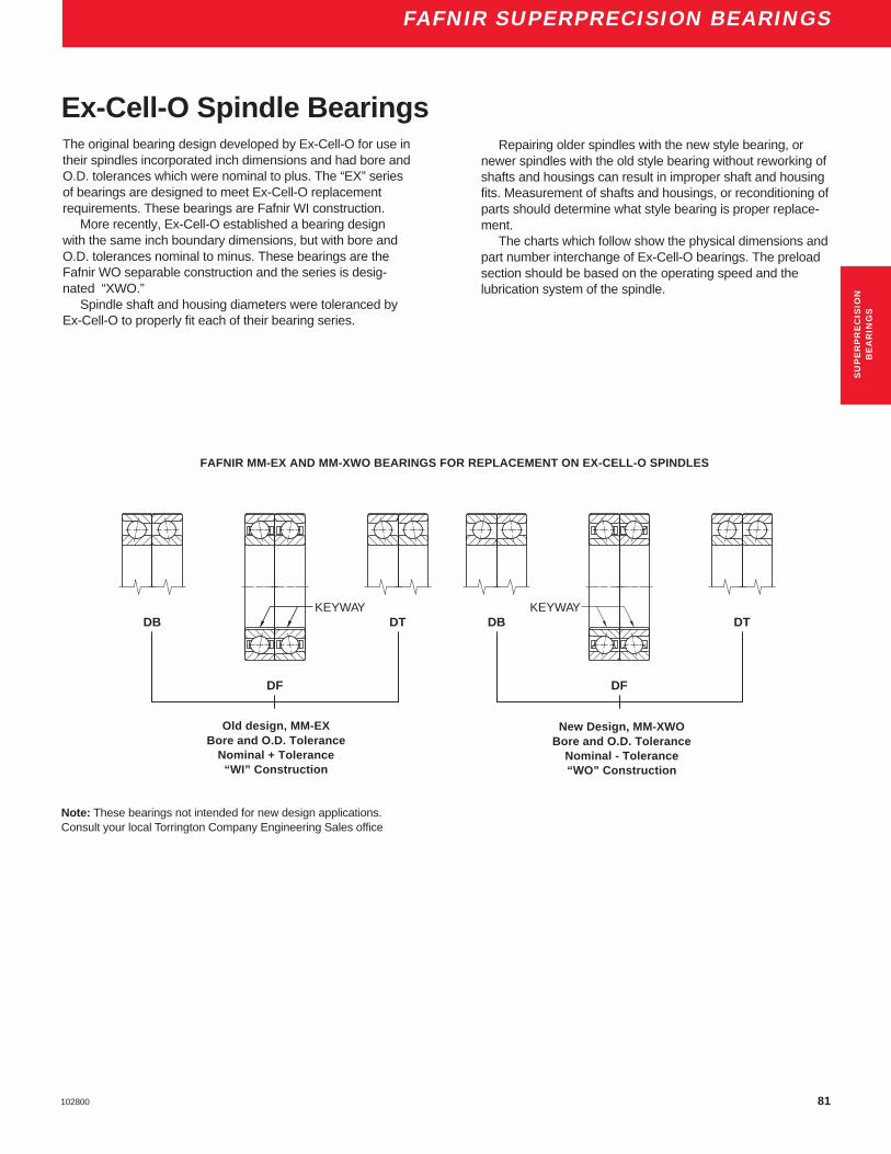
81102800
FAFNIR SUPERPRECISION BEARINGS
Old design, MM-EXBore and O.D. Tolerance
Nominal + Tolerance“WI” Construction
New Design, MM-XWOBore and O.D. Tolerance
Nominal - Tolerance“WO” Construction
FAFNIR MM-EX AND MM-XWO BEARINGS FOR REPLACEMENT ON EX-CELL-O SPINDLES
KEYWAYDTDB
DF
KEYWAYDTDB
DF
Ex-Cell-O Spindle BearingsThe original bearing design developed by Ex-Cell-O for use intheir spindles incorporated inch dimensions and had bore andO.D. tolerances which were nominal to plus. The “EX” seriesof bearings are designed to meet Ex-Cell-O replacementrequirements. These bearings are Fafnir WI construction.
More recently, Ex-Cell-O established a bearing designwith the same inch boundary dimensions, but with bore andO.D. tolerances nominal to minus. These bearings are theFafnir WO separable construction and the series is desig-nated “XWO.”
Spindle shaft and housing diameters were toleranced byEx-Cell-O to properly fit each of their bearing series.
Repairing older spindles with the new style bearing, ornewer spindles with the old style bearing without reworking ofshafts and housings can result in improper shaft and housingfits. Measurement of shafts and housings, or reconditioning ofparts should determine what style bearing is proper replace-ment.
The charts which follow show the physical dimensions andpart number interchange of Ex-Cell-O bearings. The preloadsection should be based on the operating speed and thelubrication system of the spindle.
Note: These bearings not intended for new design applications.Consult your local Torrington Company Engineering Sales office
SU
PE
RP
RE
CIS
ION
BE
AR
ING
S

82 102800
FAFNIR SUPERPRECISION BEARINGS
Fafnir Ex-Cell-O Preload Bore O.D. Width of Maximum SpeedBearing Number Part No. lbs. (in.) (in.) Pair (in.) (RPM)
MM20EXCR DU FS223 20 0 0.3752/.3750 1.1252/1.1250 0.6875/.6775 65000MM30EXCR DU FS223 30 0 0.6252/.6250 1.5002/1.5000 1.0000/9900 35000MM30EXCR DU 5 # 30 5 0.6252/.6250 1.5002/1.5000 1.0000/9900 25000MM50EXCR DU FS223 50 0 0.8127/.8125 2.0002/2.0000 1.0000/9900 30000MM50EXCR DU 10 # 50 10 0.8127/.8125 2.0002/2.0000 1.0000/9900 18000
MM50EXCR DU 50 # 50 50 0.8127/.8125 2.0002/2.0000 1.0000/9900 5000*MM55EXCR DU 10 # 55 10 0.8127/.8125 2.0002/2.0000 1.0000/9900 22000MM57EXCR DU FS223 57 0 1.0627/1.0625 2.2502/2.2500 1.0000/9900 30000MM57EXCR DU 10 # 57 10 1.0627/1.0625 2.2502/2.2500 1.0000/9900 15000MM57EXCR DU 50 # 57 50 1.0627/1.0625 2.2502/2.2500 1.0000/9900 5000
MM67EXCR DU FS223 67 0 1.2502/1.2500 2.4377/2.4375 1.2500/1.2400 30000MM67EXCR DU 10 # 67 10 1.2502/1.2500 2.4377/2.4375 1.2500/1.2400 12500MM67EXCR DU 30 # 67 30 1.2502/1.2500 2.4377/2.4375 1.2500/1.2400 7500MM67EXCR DU 75 # 67 75 1.2502/1.2500 2.4377/2.4375 1.2500/1.2400 4500MM90EXCR DU 20 # 90 20 1.6252/1.6250 3.4377/3.4375 1.6250/1.6150 10000
MM90EXCR DU 100 # 90 100 1.6252/1.6250 3.4377/3.4375 1.6250/1.6150 4500MM90EXCR DU 150 # 90 150 1.6252/1.6250 3.4377/3.4375 1.6250/1.6150 2700MM90EXCR DU 250 # 90 250 1.6252/1.6250 3.4377/3.4375 1.6250/1.6150 900
**MM92EXCR DU 20 # 92 20 1.7502/1.7500 3.4377/3.4375 1.6250/1.6150 12000**MM92EXCR DU 100 # 92 100 1.7502/1.7500 3.4377/3.4375 1.6250/1.6150 4500
**MM92EXCR DU 150 # 92 150 1.7502/1.7500 3.4377/3.4375 1.6250/1.6150 2700**MM92EXCR DU 250 # 92 250 1.7502/1.7500 3.4377/3.4375 1.6250/1.6150 900
MM115EXCR DU 30 # 115 30 2.2502/2.2500 4.7502/4.7500 2.2500/2.2400 5000MM115EXCR DU 250 # 115 250 2.2502/2.2500 4.7502/4.7500 2.2500/2.2400 3600MM115EXCR DU 350 # 115 350 2.2502/2.2500 4.7502/4.7500 2.2500/2.2400 1800
MM135EXCR DU 20 # 135 20 1.2502/1.2500 2.6877/2.6875 1.2500/1.2400 8000MM135EXCR DU 75 # 135 75 1.2502/1.2500 2.6877/2.6875 1.2500/1.2400 4000MM155EXCR DU 150 # 155 150 2.7502/2.7500 4.7502/4.7500 2.2500/2.2400 4000MM155EXCR DU 300 # 155 300 2.7502/2.7500 4.7502/4.7500 2.2500/2.2400 1800MM165EXCR DU 200 # 165 200 3.5002/3.5000 6.3127/6.3125 3.0000/2.9900 2800MM165EXCR DU 400 # 165 400 3.5002/3.5000 6.3127/6.3125 3.0000/2.9900 1200
* Four slots in outer ring faces. Do not interchange with MM-XWO.
** No keyway in bore. MM-XWO produced to nominal minus tolerance.
FS-223 Zero to negative preload. MM-EX produced to nominal plus tolerance.
MM-EXReplacement BearingsFor Ex-Cell-O Spindles

83102800
FAFNIR SUPERPRECISION BEARINGS
Fafnir Ex-Cell-O Preload Bore O.D. Width of Maximum Speed
Bearing Number Part No. lbs. (in.) (in.) Pair (in.) Grease Oil Mist
MM20XWOCRDU E9103A XLO 20-107 0 0.37500/.37485 1.1250/1.1248 0.6875/.6675 40000 65000 80000MM30XWOCRDU E9103C XLO 30-57 10 0.62500/.62485 1.5000/1.4998 1.000/.980 27000 30000 35000MM30XWOCRDU E9103A XLO 30-107 0 0.62500/.62485 1.5000/1.4998 1.000/.980 35000 40000 60000MM55XWOCRDU E9103E XLO 55-27 50 0.81250/.81235 2.0000/1.9998 1.000/.980 5000 8000 12000MM55XWOCRDU E9103C XLO 55-57 20 0.81250/.81235 2.0000/1.9998 1.000/.980 20000 22000 24000
MM55XWOCRDU E9103A XLO 55-107 0 0.81250/.81235 2.0000/1.9998 1.000/.980 24000 27000 45000MM57XWOCRDU E9103F XLO 57-17 100 1.06250/1.06235 2.2500/2.2498 1.000/.980 2000 4000 6000MM57XWOCRDU E9103C XLO 57-57 20 1.06250/1.06235 2.2500/2.2498 1.000/.980 18000 20000 22000MM57XWOCRDU E9103A XLO 57-107 0 1.06250/1.06235 2.2500/2.2498 1.000/.980 22000 25000 35000MM67XWOCRDU E9103F XLO 67-17 90 1.2500/1.2498 2.4375/2.4373 1.250/1.230 36000 4500 6000
MM67XWOCRDU E9103C XLO 67-57 20 1.2500/1.2498 2.4375/2.4373 1.250/1.230 12500 15000 20000MM67XWOCRDU E9103A XLO 67-107 0 1.2500/1.2498 2.4375/2.4373 1.250/1.230 16000 20000 30000MM90XWOCRDU E9103F XLO 90-17 250 1.6250/1.6248 3.4375/3.4372 1.625/1.605 1000 2000 4000MM90XWOCRDU E9103D XLO 90-47 175 1.6250/1.6248 3.4375/3.4372 1.625/1.605 3000 5000 8000MM90XWOCRDU E9103C XLO 90-57 100 1.6250/1.6248 3.4375/3.4372 1.625/1.605 5000 7000 11000
MM90XWOCRDU E9103A XLO 90-77 20 1.6250/1.6248 3.4375/3.4372 1.625/1.605 10000 14000 20000MM115XWOCRDU E9103E XLO 115-27 300 2.2500/2.2498 4.7500/4.7496 2.250/2.230 1000 2000 3000MM115XWOCRDU E9103C XLO 115-47 150 2.2500/2.2498 4.7500/4.7496 2.250/2.230 3000 4500 7000MM115XWOCRDU E9103A XLO 115-77 30 2.2500/2.2498 4.7500/4.7496 2.250/2.230 6000 8000 15000MM135XWOCRDU E9103C XLO 135-67 50 1.2500/1.2498 2.6875/2.6873 1.250/1.230 6000 7000 12000
MM135XWOCRDU E9103A XLO 135-107 0 1.2500/1.2498 2.6875/2.6873 1.250/1.230 15000 19000 28000MM155XWOCRDU E9103D XLO 155-37 300 2.7500/2.7498 4.7500/4.7496 2.250/2.230 1000 2000 3000MM155XWOCRDU E9103B XLO 155-67 150 2.7500/2.7498 4.7500/4.7496 2.250/2.230 4000 5000 6500MM155XWOCRDU E9103A XLO 155-87 50 2.7500/2.7498 4.7500/4.7496 2.250/2.230 6000 7000 10000MM165XWOCRDU E9103E XLO 165-27 800 3.50000/3.49975 6.3125/6.3121 3.000/2.980 500 1000 2000
MM165XWOCRDU E9103C XLO 165-57 250 3.50000/3.49975 6.3125/6.3121 3.000/2.980 2000 3000 5000MM165XWOCRDU E9103A XLO 165-87 50 3.50000/3.49975 6.3125/6.3121 3.000/2.980 5000 6500 9000
Do not interchange with MM-EX.
MM-XWO produced to nominal minus tolerance.
MM-EX produced to nominal plus tolerance.
* Standard preload levels are shown. Other preload variations are attainable by spacer adjustment.
MM-XWOReplacement BearingsFor Ex-Cell-O Spindles
SU
PE
RP
RE
CIS
ION
BE
AR
ING
S
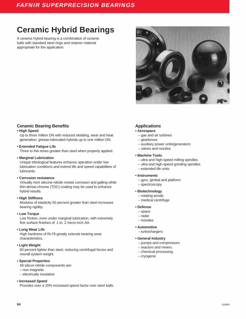
84 102800
FAFNIR SUPERPRECISION BEARINGS
Ceramic Hybrid BearingsA ceramic hybrid bearing is a combination of ceramicballs with standard steel rings and retainer materialappropriate for the application.
Ceramic Bearing Benefits• High Speed
Up to three million DN with reduced skidding, wear and heatgeneration; grease-lubricated hybrids up to one million DN.
• Extended Fatigue LifeThree to five times greater than steel when properly applied.
• Marginal LubricationUnique tribological features enhance operation under lowlubrication conditions and extend life and speed capabilities oflubricants.
• Corrosion resistanceVirtually inert silicone nitride resists corrosion and galling whilethin-dense-chrome (TDC) coating may be used to enhancehybrid results.
• High StiffnessModulus of elasticity 50 percent greater than steel increasesbearing rigidity.
• Low TorqueLow friction, even under marginal lubrication, with extremelyfine surface finishes of .1 to .2 micro-inch AA.
• Long Wear LifeHigh hardness of Rc78 greatly extends bearing wearcharacteristics.
• Light Weight60 percent lighter than steel, reducing centrifugal forces andoverall system weight.
• Special PropertiesAll silicon nitride components are:– non-magnetic– electrically insulative
• Increased SpeedProvides over a 20% increased speed factor over steel balls.
Applications• Aerospace
– gas and air turbines– gearboxes– auxiliary power units/generators– valves and nozzles
• Machine Tools– ultra and high-speed milling spindles– ultra and high-speed grinding spindles– extended life units
• Instruments– gyro, gimbal and platform– spectroscopy
• Biotechnology– rotating anode– medical centrifuge
• Defense– space– radar– missiles
• Automotive– turbochargers
• General Industry– pumps and compressors– reactors and mixers– chemical processing– cryogenic

85102800
FAFNIR SUPERPRECISION BEARINGS
16 –
14 –
12 –
10 –
8 –
6 –
4 –
2 –
0 –
Tem
per
atu
re R
ise
(C)
52100 Steel Balls
CeramicBalls
5000 10000 15000 20000 25000 30000Spindle Speed (RPM)
Temperature vs Speed2MMV99110WN (50 mm bore). Grease lubrication.
5x
1.5x1000 –
100 –
10 –
1 –
0.1 –.5 1.0 1.5 2.0 DN (millions)
Hours x 1000
Life vs Ball Material2MMV99110WN DUL (DB Mounting)
Si (3)N (4)
52100Steel
Industry’s present day applications place demands onmachinery that could not be imagined as little as adecade ago.
Machinery is expected to be more efficient, reliable,faster and last longer with less maintenance. In the future,even the great reliability and wide versatility of the stan-dard Torrington steel bearing may be challenged.
By incorporating ceramic and state-of-the-art bearingtechnology, The Torrington Company has developed thehybrid ceramic bearing. Designed with increased speedcapabilities, the hybrid ceramic bearing features a higherelastic modulus for greater stiffness. Its lower frictioncharacteristics result in less skidding than the all-steelbearing.
The Torrington Company Sales Engineering profes-sional in your area can assist you in determining if thehybrid ceramic bearing is suitable for your application.
When ordering a ceramic hybrid bearing add “C” tothe part number after the prefix that specifies precisiontype, i.e. 2MMV C9110HX or 2MMVC99110WN.
Material Properties100 -
90 -
80 -
70 -
60 -
50 -
40 -
30 -
20 -
10 -
0 -Density Rigidity Friction Fracture Thermal
Limit Expansion
Steel Ceramic
SU
PE
RP
RE
CIS
ION
BE
AR
ING
S
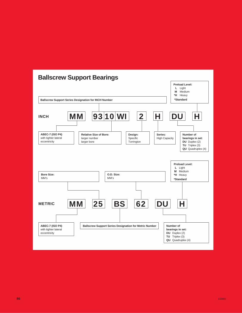
Ballscrew Support Bearings
Ballscrew Support Series Designation for INCH Number
Preload Level:L LightM Medium*H Heavy
*Standard
INCH
ABEC-7 (ISO P4)with tighter lateraleccentricity
Relative Size of Bore:larger numberlarger bore
Design:SpecificTorrington
Series:High Capacity
Number ofbearings in set:DU Duplex (2)TU Triplex (3)QU Quadruplex (4)
Bore Size:MM’s
O.D. Size:MM’s
Preload Level:L LightM Medium*H Heavy
*Standard
METRIC MM
ABEC-7 (ISO P4)with tighter lateraleccentricity
Ballscrew Support Series Designation for Metric Number Number ofbearings in set:DU Duplex (2)TU Triplex (3)QU Quadruplex (4)
25 BS 62 DU H
MM 9310 WI 2 H DU H
86 102800

BA
LL
SC
RE
WS
UP
PO
RT
BE
AR
ING
S
FAFNIR BALLSCREW SUPPORT BEARINGSFAFNIR BALLSCREW SUPPORT BEARINGSFAFNIR BALLSCREW SUPPORT BEARINGS
87102800

88 102800
FAFNIR BALLSCREW SUPPORT BEARINGS
DIMENSIONS – TOLERANCESAll inch tolerance in .0001 units
Bearing Outside Maximum BallNumber Bore Diameter (Single) Width * Fillet Radius Complement
Nominal Tolerance Nominal Tolerance Nominal Tolerance Bearing Corner
Dimension +.0000" Dimension +.0000" Dimension +.0000" will Clear **+.0µm +.0µm +.0µm
d to minus D to minus C to minus Dia.
in. mm in. µm in. mm in. µm in. mm in. µm in. mm Qty. in.
MM9306WI2H 0.7874 20 2.0 5 1.8504 47 2.5 6 0.6250 15.9 50 130 0.031 0.8 12 5⁄16MM17BS47 0.6693 17 1.5 4 1.8504 47 2.5 6 0.5906 15 32 80 0.031 0.8 12 5⁄16MM20BS47 0.7874 20 2.0 5 1.8504 47 2.5 6 0.5906 15 50 130 0.031 0.8 12 5⁄16
MM25BS52 0.0983 25 2.0 5 2.0472 52 3.0 7 0.5906 15 50 130 0.031 0.8 13 5⁄16
MM9308WI2H 0.9385 23.8 2.0 5 2.4409 62 3.0 7 0.6250 15.9 50 130 0.031 0.8 17 5⁄16MM25BS62 0.9843 25 2.0 5 2.4409 62 3.0 7 0.5906 15 50 130 0.031 0.8 17 5⁄16MM30BS62 1.1811 30 2.0 5 2.4409 62 3.0 7 0.5906 15 50 130 0.031 0.8 17 5⁄16
MM9310WI2H 1.5000 38.1 2.5 6 2.8346 72 3.0 7 0.6250 15.9 50 130 0.031 0.8 18 11⁄32MM30BS72 1.1811 30 2.0 5 2.8346 72 3.0 7 0.5906 15 50 130 0.031 0.8 18 11⁄32MM35BS72 1.3780 35 2.5 6 2.8346 72 3.0 7 0.5906 15 50 130 0.031 0.8 18 11⁄32MM40BS72 1.5748 40 2.5 6 2.8346 72 3.0 7 0.5906 15 50 130 0.031 0.8 18 11⁄32
MM9311WI3H 1.7510 44.5 2.5 6 3.0000 76.2 3.0 7 0.6250 15.9 50 130 0.031 0.8 20 11⁄32MM45BS75 1.7717 45 2.5 6 2.9528 75 3.0 7 0.5906 15 50 130 0.031 0.8 20 11⁄32
MM9313WI5H 2.2500 57.2 3.0 7 3.5433 90 3.0 8 0.6250 15.9 60 150 0.031 0.8 24 11⁄32MM40BS90 1.5748 40 2.5 6 3.5433 90 3.0 8 0.5906 15 50 130 0.031 0.8 24 11⁄32MM50BS90 1.9685 50 2.5 6 3.5433 90 3.0 8 0.5906 15 50 130 0.031 0.8 24 11⁄32MM55BS90 2.1654 55 3.0 7 3.5433 90 3.0 8 0.5906 15 60 150 0.031 0.8 24 11⁄32
MM35BS100 1.3780 35 2.5 6 3.9370 100 3.0 8 0.7874 20 50 130 0.031 0.8 18 1⁄2MM40BS100 1.5748 40 2.5 6 3.9370 100 3.0 8 0.7874 20 50 130 0.031 0.8 18 1⁄2MM45BS100 1.7717 45 2.5 6 3.9370 100 3.0 8 0.7874 20 50 130 0.031 0.8 18 1⁄2MM50BS100 1.9685 50 2.5 6 3.9370 100 3.0 8 0.7874 20 50 130 0.031 0.8 18 1⁄2
MM9316WI3H 3.0000 76.2 3.0 7 4.3307 110 3.0 8 0.6250 15.9 60 150 0.031 0.8 30 11⁄32MM75BS110 2.9528 75 3.0 7 4.3307 110 3.0 8 0.5906 15 60 150 0.031 0.8 30 11⁄32
MM55BS120 2.1654 55 3.0 7 4.7244 120 3.0 8 0.7874 20 60 150 0.039 1.0 21 1⁄2MM60BS120 2.3622 60 3.0 7 4.7244 120 3.0 8 0.7874 20 60 150 0.039 1.0 21 1⁄2
MM9321WI3 4.0000 101.6 3.0 8 5.7087 145 3.5 9 0.8750 22.2 80 210 0.039 1.0 37 3⁄8MM100BS150 3.9370 100 3.0 8 5.9055 150 3.5 9 0.7874 20 60 150 0.039 1.0 26 1⁄2
MM9326WI6H 5.0000 127 3.0 8 7.0866 180 4.0 10 0.8750 22.2 100 260 0.039 1.0 35 1⁄2
* Refer to E4 page for width tolerance of preloaded bearings.** ABMA std. 20 (ras max).
Ballscrew Support BearingsTo meet the requirements of the servo-controlled machinery field,Torrington has developed a new series of ball bearings speciallydesigned for ballscrew applications. Design criteria for thesebearings with maximum axial rigidity, low drag torque, andextreme control of lateral eccentricity.
These bearings are manufactured to ABEC-7 tolerances andare of the nonseparable angular-contact type design with a 60°contact angle and maximum complement of balls.These bearingsare supplied prelubricated with heavy duty grease NLGI #2 .Bearings are supplied packaged in DB arrangement. However,they can be mounted in duplexed pairs and in multiplexed sets ineither Back-to-Back (DB), Face-to-Face (DF) or Tandem (DT)arrangements.
Standard sizes are available and are stocked and packaged asduplex pairs, triplex sets or quadruplex sets. These bearings aredesigned primarily for ballscrew applications and should not beconsidered in other areas such as spindles or gear-box shaftingwithout approval by our Engineering Department. These bearingsare offered in both standard inch and metric envelope dimensions.

89102800
FAFNIR BALLSCREW SUPPORT BEARINGS
d D
C X 2
PHYSICAL CHARACTERISTICS – LOAD RATINGSBearing Weight Static Limiting Thrust Extended Thrust Maximum Axial Spring Drag Torque of Preload *Number Per Bearing Capacity Dynamic Axial Speed Constant Preloaded Set
Load Ratings
Tl Cae Heavy(DUH)
DUPLEX lbs kg lbs N lbs N RPM 106 lbs/in 106 N/m in-lbs N-m lbs(per set) N
MM9306WI2HDUH 0.28 0.129 5,600 24,900 5,600 24,900 4,400 4.3 750 2.83 0.320 700 3110MM17BS47DUH 0.29 0.132 5,600 24,900 5,600 24,900 4,400 4.3 750 2.83 0.320 700 3110MM20BS47DUH 0.27 0.122 5,600 24,900 5,600 24,900 4,400 4.3 750 2.83 0.320 700 3110
MM25BS52DUH 0.31 0.140 6,100 27,100 5,850 26,000 4,400 4.4 780 2.17 0.245 600 2700
MM9308WI2HDUH 0.56 0.252 8,000 35,600 6,700 29,800 3,200 6.0 1050 3.89 0.439 1000 4450MM25BS62DUH 0.51 0.233 8,000 35,600 6,700 29,800 3,200 6.0 1050 3.89 0.439 1000 4450MM30BS62DUH 0.46 0.208 8,000 35,600 6,700 29,800 3,200 6.0 1050 3.89 0.439 1000 4450
MM9310WI2HDUH 0.62 0.281 10,200 45,400 8,150 36,300 2,500 7.2 1260 3.89 0.439 1400 6230MM30BS72DUH 0.70 0.317 10,200 45,400 8,150 36,300 2,500 7.2 1260 3.89 0.439 1400 6230MM35BS72DUH 0.63 0.287 10,200 45,400 8,150 36,300 2,500 7.2 1260 3.89 0.439 1400 6230MM40BS72DUH 0.56 0.252 10,200 45,400 8,150 36,300 2,500 7.2 1260 3.89 0.439 1400 6230
MM9311WI3HDUH 0.63 0.284 11,400 50,700 8,650 38,500 2,100 7.9 1380 4.96 0.560 1500 6670MM45BS75DUH 0.55 0.248 11,400 50,700 8,650 38,500 2,100 7.9 1380 4.96 0.560 1500 6670
MM9313WI5HDUH 0.80 0.361 13,700 60,900 9,300 41,400 2,000 9.5 1660 7.26 0.820 1800 8010MM40BS90DUH 1.09 0.496 13,700 60,900 9,300 41,400 2,000 9.5 1660 7.26 0.820 1800 8010MM50BS90DUH 0.91 0.413 13,700 60,900 9,300 41,400 2,000 9.5 1660 7.26 0.820 1800 8010MM55BS90DUH 0.80 0.364 13,700 60,900 9,300 41,400 2,000 9.5 1660 7.26 0.820 1800 8010
MM35BS100DUH 1.90 0.862 21,000 93,400 16,000 71,200 1,700 10.0 1750 9.03 1.020 2900 12900MM40BS100DUH 1.80 0.816 21,000 93,400 16,000 71,200 1,700 10.0 1750 9.03 1.020 2900 12900MM45BS100DUH 1.68 0.763 21,000 93,400 16,000 71,200 1,700 10.0 1750 9.03 1.020 2900 12900MM50BS100DUH 1.55 0.705 21,000 93,400 16,000 71,200 1,700 10.0 1750 9.03 1.020 2900 12900
MM9316WI3HDUH 1.04 0.472 17,300 77,000 10,000 44,500 1,400 11.9 2080 8.85 1.000 2200 9790MM75BS110DUH 1.02 0.463 17,300 77,000 10,000 44,500 1,400 11.9 2080 8.85 1.000 2200 9790
MM55BS120DUH 2.49 1.128 30,000 133,400 17,000 75,600 1,400 12.3 2150 12.04 1.360 3500 15570MM60BS120DUH 2.33 1.058 30,000 133,400 17,000 75,600 1,400 12.3 2150 12.04 1.360 3500 15570
MM9321WI3DUH 2.60 1.178 26,000 115,600 12,900 57,400 1,000 19.4 3400 19.30 2.180 4800 21350MM100BS150DUH 2.83 1.282 26,000 115,600 12,900 57,400 1,000 19.4 3400 19.30 2.180 4800 21350
MM9326WI6HDUH 3.85 1.748 42,000 186,800 21,200 94,300 750 20.7 3620 35.10 3.966 6000 26690
* Heavy preload is the standard.
Duplex Mounting
BA
LL
SC
RE
WS
UP
PO
RT
BE
AR
ING
SRADIAL LOAD RATING AT 33 1⁄ 3 RPMBased on 1500 hours L 10 Life and Permissible Speed

90 102800
FAFNIR BALLSCREW SUPPORT BEARINGS
PHYSICAL CHARACTERISTICS – LOAD RATINGSBearing Weight Static Limiting Thrust Extended Thrust Maximum Axial Spring Drag Torque of Preload *Number Per Bearing Capacity Dynamic Axial Speed Constant Preloaded Set
Load Ratings
Tl Cae Heavy(QUH)
Quadruplex lbs kg lbs N lbs N RPM 106 lbs/in 106 N/m in-lbs N-m lbs(per set) N
MM9306WI2HQUH 0.28 0.129 11,200 49,800 9,100 40,500 3,700 8.6 1510 5.66 0.639 1400 6230MM17BS47QUH 0.29 0.132 11,200 49,800 9,100 40,500 3,700 8.6 1510 5.66 0.639 1400 6230MM20BS47QUH 0.27 0.122 11,200 49,800 9,100 40,500 3,700 8.6 1510 5.66 0.639 1400 6230
MM25BS52QUH 0.31 0.140 12,200 54,300 9,500 42,300 3,700 8.9 1560 4.34 0.490 1200 5400
MM9308WI2HQUH 0.56 0.252 16,000 71,200 10,900 48,500 2,700 12.0 2100 7.78 0.879 2000 8900MM25BS62QUH 0.51 0.233 16,000 71,200 10,900 48,500 2,700 12.0 2100 7.78 0.879 2000 8900MM30BS62QUH 0.46 0.208 16,000 71,200 10,900 48,500 2,700 12.0 2100 7.78 0.879 2000 8900
MM9310WI2HQUH 0.62 0.281 20,400 90,700 13,200 58,700 2,100 14.4 2520 7.78 0.879 2800 12450MM30BS72QUH 0.70 0.317 20,400 90,700 13,200 58,700 2,100 14.4 2520 7.78 0.879 2800 12450MM35BS72QUH 0.63 0.287 20,400 90,700 13,200 58,700 2,100 14.4 2520 7.78 0.879 2800 12450MM40BS72QUH 0.56 0.252 20,400 90,700 13,200 58,700 2,100 14.4 2520 7.78 0.879 2800 12450
MM9311WI3HQUH 0.63 0.284 22,800 101,400 14,100 62,700 1,800 15.8 2770 9.92 1.121 3000 13340MM45BS75QUH 0.55 0.248 22,800 101,400 14,100 62,700 1,800 15.8 2770 9.92 1.121 3000 13340
MM9313WI5HQUH 0.80 0.361 27,400 121,900 15,100 67,200 1,700 19.0 3330 14.52 1.640 3600 16010MM40BS90QUH 1.09 0.496 27,400 121,900 15,100 67,200 1,700 19.0 3330 14.52 1.640 3600 16010MM50BS90QUH 0.91 0.413 27,400 121,900 15,100 67,200 1,700 19.0 3330 14.52 1.640 3600 16010MM55BS90QUH 0.80 0.364 27,400 121,900 15,100 67,200 1,700 19.0 3330 14.52 1.640 3600 16010
MM35BS100QUH 1.90 0.862 42,000 186,800 26,000 115,600 1,400 20.0 3500 18.06 2.040 5800 25800MM40BS100QUH 1.80 0.816 42,000 186,800 26,000 115,600 1,400 20.0 3500 18.06 2.040 5800 25800MM45BS100QUH 1.68 0.763 42,000 186,800 26,000 115,600 1,400 20.0 3500 18.06 2.040 5800 25800MM50BS100QUH 1.55 0.705 42,000 186,800 26,000 115,600 1,400 20.0 3500 18.06 2.040 5800 25800
MM9316WI3HQUH 1.04 0.472 34,600 153,900 16,200 72,100 1,200 23.8 4170 17.70 2.000 4400 19570MM75BS110QUH 1.02 0.463 34,600 153,900 16,200 72,100 1,200 23.8 4170 17.70 2.000 4400 19570
MM55BS120QUH 2.49 1.128 60,000 266,900 27,600 122,800 1,200 24.6 4310 24.08 2.721 7000 31140MM60BS120QUH 2.33 1.058 60,000 266,900 27,600 122,800 1,200 24.6 4310 24.08 2.721 7000 31140
MM9321WI3QUH 2.60 1.178 52,000 231,300 21,000 93,400 900 38.8 6790 38.60 4.361 9600 42700MM100BS150QUH 2.83 1.284 52,000 231,300 21,000 93,400 900 38.8 6790 38.60 4.361 9600 42700
MM9326WI6HQUH 3.85 1.748 84,000 373,600 34,400 153,000 600 41.4 7250 70.20 7.931 12000 53380
* Heavy preload is the standard.
Ball Screw Support SeriesThe recommended maximum limitations on ballscrew bearingspeed limits are based on 50% active duty cycle and a tenminute total cycle period. Speed limitations may be increasedsomewhat with lighter duty cycles. Please consult ourEngineering Department regarding bearing speeds andduty cycles.
RADIAL LOAD RATING AT 33 1⁄ 3 RPMBased on 1500 hours L 10 Life and Permissible Speed
d D
C (WIDTH) X 4
Quadruplex Mounting
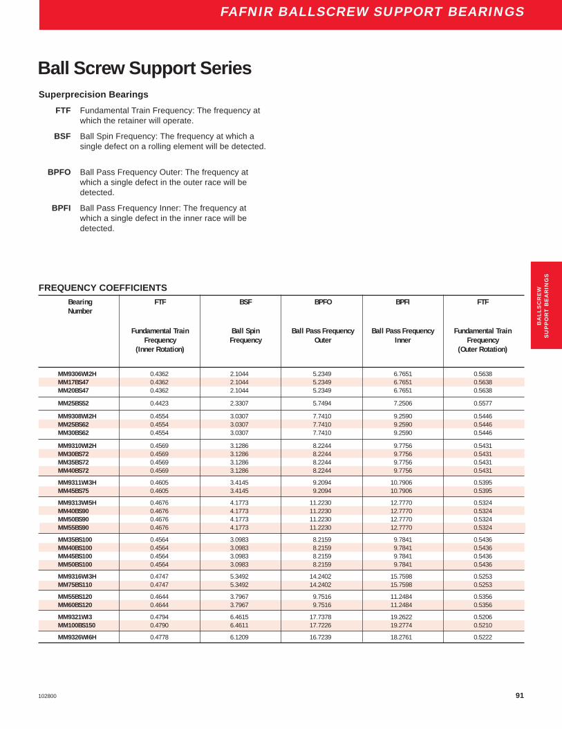
91102800
FAFNIR BALLSCREW SUPPORT BEARINGS
FREQUENCY COEFFICIENTSBearing FTF BSF BPFO BPFI FTFNumber
Fundamental Train Ball Spin Ball Pass Frequency Ball Pass Frequency Fundamental TrainFrequency Frequency Outer Inner Frequency
(Inner Rotation) (Outer Rotation)
MM9306WI2H 0.4362 2.1044 5.2349 6.7651 0.5638MM17BS47 0.4362 2.1044 5.2349 6.7651 0.5638MM20BS47 0.4362 2.1044 5.2349 6.7651 0.5638
MM25BS52 0.4423 2.3307 5.7494 7.2506 0.5577
MM9308WI2H 0.4554 3.0307 7.7410 9.2590 0.5446MM25BS62 0.4554 3.0307 7.7410 9.2590 0.5446MM30BS62 0.4554 3.0307 7.7410 9.2590 0.5446
MM9310WI2H 0.4569 3.1286 8.2244 9.7756 0.5431MM30BS72 0.4569 3.1286 8.2244 9.7756 0.5431MM35BS72 0.4569 3.1286 8.2244 9.7756 0.5431MM40BS72 0.4569 3.1286 8.2244 9.7756 0.5431
MM9311WI3H 0.4605 3.4145 9.2094 10.7906 0.5395MM45BS75 0.4605 3.4145 9.2094 10.7906 0.5395
MM9313WI5H 0.4676 4.1773 11.2230 12.7770 0.5324MM40BS90 0.4676 4.1773 11.2230 12.7770 0.5324MM50BS90 0.4676 4.1773 11.2230 12.7770 0.5324MM55BS90 0.4676 4.1773 11.2230 12.7770 0.5324
MM35BS100 0.4564 3.0983 8.2159 9.7841 0.5436MM40BS100 0.4564 3.0983 8.2159 9.7841 0.5436MM45BS100 0.4564 3.0983 8.2159 9.7841 0.5436MM50BS100 0.4564 3.0983 8.2159 9.7841 0.5436
MM9316WI3H 0.4747 5.3492 14.2402 15.7598 0.5253MM75BS110 0.4747 5.3492 14.2402 15.7598 0.5253
MM55BS120 0.4644 3.7967 9.7516 11.2484 0.5356MM60BS120 0.4644 3.7967 9.7516 11.2484 0.5356
MM9321WI3 0.4794 6.4615 17.7378 19.2622 0.5206MM100BS150 0.4790 6.4611 17.7226 19.2774 0.5210
MM9326WI6H 0.4778 6.1209 16.7239 18.2761 0.5222
BA
LL
SC
RE
WS
UP
PO
RT
BE
AR
ING
S
Superprecision Bearings
FTF Fundamental Train Frequency: The frequency atwhich the retainer will operate.
BSF Ball Spin Frequency: The frequency at which asingle defect on a rolling element will be detected.
BPFO Ball Pass Frequency Outer: The frequency atwhich a single defect in the outer race will bedetected.
BPFI Ball Pass Frequency Inner: The frequency atwhich a single defect in the inner race will bedetected.
Ball Screw Support Series

92 102800
FAFNIR BALLSCREW SUPPORT BEARINGS
BSBU DStandard andHeavy Duty BearingsThe BSBU D series of bearing cartridge units were designedand developed to give the machine manufacturer a ready madeunit providing excellent stiffness and accuracy in ballscrewapplications. The unit incorporates a flange enabling it to bebolted to a flat surface perpendicular to the ballscrew axis.
These units combine the features of MM-BS-DU (Duplex)ballscrew bearings with an accurately manufactured housingand laminar ring seals.
Each unit is prepacked with a measured quantity of highquality bearing grease and requires no further lubrication.
Units are supplied with the bearings in pairs or quad setsmounted in the “DB” (“O”) arrangement. Other bearing arrange-ments can be accommodated if required and in these casesplease contact us with details of your requirements.
Consult our Engineering Department for recommended shaftand housing fits.
STANDARD SERIES – DIMENSIONAL TOLERANCES ± 0.005" (± .13 MM) UNLESS OTHERWISE STATED.Shaft Unit C d d1 d2 d3 D D1 D2 D3 E F K L N P Wt.Diam. Number
in. in. in. in. in. in. in. in. in. in. in. in. in. in. in. lbs.mm mm mm mm mm mm mm mm mm mm mm mm mm mm mm mm kg
17 BSBU17D60 1.85 0.6693 0.17 0.26 1.42 2.3622 1.02 2.52 3.54 1.742 1.67 1.26 0.51 2.99 1.26 2.420.6691 2.3617 1.702
47.0 17.000 4.3 6.6 36.0 60.000 26.0 64.0 90.0 44.26 42.5 32.0 13.0 76.0 32.0 1.116.996 59.987 43.24
20 BSBU20D60 1.85 0.7874 0.17 0.26 1.42 2.3622 1.02 2.52 3.54 1.742 1.67 1.26 0.51 2.99 1.26 2.420.7872 2.3617 1.702
47.0 20.000 4.3 6.6 36.0 60.000 26.0 64.0 90.0 44.26 42.5 32.0 13.0 76.0 32.0 1.119.996 59.987 43.24
25 BSBU25D80 2.05 0.9842 0.17 0.36 1.97 3.1496 1.57 3.46 4.72 1.979 2.34 1.26 0.59 4.02 1.73 5.060.9841 3.1491 1.938
52.0 25.000 4.3 9.2 50.0 80.000 40.0 88.0 120.0 50.26 59.5 32.0 15.0 102.0 44.0 2.324.996 79.987 49.24
30 BSBU30D80 2.05 1.1811 0.17 0.36 1.97 3.1496 1.57 3.46 4.72 1.979 2.34 1.26 0.59 4.02 1.73 4.841.1809 3.1491 1.938
52.0 30.000 4.3 9.2 50.0 80.000 40.0 88.0 120.0 50.26 59.5 32.0 15.0 102.0 44.0 2.229.996 79.987 49.24
35 BSBU35D90 2.05 1.378 0.17 0.36 2.36 3.5433 1.81 3.86 5.12 1.979 2.62 1.26 0.59 4.45 1.93 7.041.3778 3.5427 1.938
52.0 35.000 4.3 9.2 60 90.000 46 98 130 50.26 66.5 32.0 15.0 113.0 49 3.234.995 89.985 49.24
40 BSBU40D90 2.05 1.5748 0.17 0.36 2.36 3.5433 1.81 3.86 5.12 1.979 2.62 1.26 0.59 4.45 1.93 6.821.5746 3.5427 1.938
52.0 40.000 4.3 9.2 60.0 90.000 46.0 98 130.0 50.26 66.5 32.0 15.0 113.0 49 3.139.995 89.985 49.24

93102800
FAFNIR BALLSCREW SUPPORT BEARINGS
BSBU 30 D 80
FA
FN
I R
30°
P
10 HOLES 'd2' EQUISPACED ON 'N' P.C. DIA.
4 HOLES 'd1' EQUISPACED ON 'F' P.C. DIA.
45°
DD
ddD
D
3
32
1
0.0002 A
0.0004 AA
K L
E
C
1 X 45°
HEAVY DUTY SERIES – DIMENSIONAL TOLERANCES ± 0.005" (± .13 MM) UNLESS OTHERWISE STATED.Shaft Unit C d d1 d2 d3 D D1 D2 D3 E F K L N P Wt.Diam. Number
in. in. in. in. in. in. in. in. in. in. in. in. in. in. in. lbs.mm mm mm mm mm mm mm mm mm mm mm mm mm mm mm mm kg
35 BSBU35D124 2.6 1.3780 0.21 0.45 2.99 4.8819 2.6 5.04 6.5 2.530 3.54 1.71 0.67 5.75 2.52 13.861.3778 4.8812 2.490
66.0 35.000 5.3 11.4 76.0 124.000 66.0 128 165.0 64.26 90.0 43.5 17.0 146.0 64.0 6.334.995 123.982 63.24
40 BSBU40D124 2.6 1.5748 0.21 0.45 2.99 4.8819 2.6 5.04 6.5 2.530 3.54 1.71 0.67 5.75 2.52 13.421.5746 4.8812 2.490
66.0 40.000 5.3 11.4 76.0 124.000 66.0 128 165.0 64.26 90.0 43.5 17.0 146.0 64.0 6.139.995 123.982 63.24
45 BSBU45D124 2.6 1.7716 0.21 0.45 2.99 4.8819 2.6 5.04 6.5 2.530 3.54 1.71 0.67 5.75 2.52 13.21.7714 4.8812 2.490
66.0 45.000 5.3 11.4 76.0 124.000 66.0 128 165.0 64.26 90.0 43.5 17.0 146.0 64.0 6.044.995 123.982 63.24
50 BSBU50D124 2.6 1.9685 0.21 0.45 2.99 4.8819 2.6 5.04 6.5 2.530 3.54 1.71 0.67 5.75 2.52 12.8981.9683 4.8812 2.490
66.0 50.000 5.3 11.4 76.0 124.000 66.0 128 165.0 64.26 90.0 43.5 17.0 146.0 64.0 5.949.995 123.982 63.24
BA
LL
SC
RE
WS
UP
PO
RT
BE
AR
ING
S

94 102800
FAFNIR BALLSCREW SUPPORT BEARINGS
BSBU QStandard andHeavy Duty BearingsThe BSBU Q series are similar in design and features tothe BSBU D series except MM-BS-QU Quadruplexbearings are used.
Consult our Engineering Department for recommendedshaft and housing fits.
STANDARD SERIES – DIMENSIONAL TOLERANCES ± .005" (± .13 mm) UNLESS OTHERWISE STATEDShaft Unit C d d1 d2 d3 D D1 D2 D3 E F K L N P Wt.Diam. Number
in. in. in. in. in. in. in. in. in. in. in. in. in. in. in. lbs.mm mm mm mm mm mm mm mm mm mm mm mm mm mm mm mm kg17 BSBU17Q60 3.03 0.6693 0.17 0.26 1.42 2.3622 1.02 2.52 3.54 2.924 1.67 1.26 0.51 2.99 1.26 3.74
0.6690 2.3617 2.86477.0 17.000 4.3 6.6 36.0 60.000 26.0 64.0 90.0 74.26 42.5 32.0 13.0 76.0 32.0 1.7
16.993 59.987 72.74
20 BSBU20Q60 3.03 0.7874 0.17 0.26 1.42 2.3622 1.02 2.52 3.54 2.924 1.67 1.26 0.51 2.99 1.26 3.740.7872 2.3617 2.864
77.0 20.000 4.3 6.6 36.0 60.000 26.0 64.0 90.0 74.26 42.5 32.0 13.0 76.0 32.0 1.719.996 59.987 72.74
25 BSBU25Q80 3.23 0.9842 0.17 0.36 1.97 3.1496 1.57 3.46 4.72 3.160 2.34 1.26 0.59 4.02 1.73 7.70.9841 3.1491 3.100
82.0 25.000 4.3 9.2 50.0 80.000 40.0 88.0 120.0 80.26 59.5 32.0 15.0 102.0 44.0 3.524.996 79.987 78.74
30 BSBU30Q80 3.23 1.1811 0.17 0.36 1.97 3.1496 1.57 3.46 4.72 3.160 2.34 1.26 0.59 4.02 1.73 7.481.1809 3.1491 3.100
82.0 30.000 4.3 9.2 50.0 80.000 40.0 88.0 120.0 80.26 59.5 32.0 15.0 102.0 44.0 3.429.995 79.987 78.74
35 BSBU35Q90 3.23 1.3780 0.17 0.36 2.36 3.5433 1.81 3.86 5.12 3.160 2.62 1.26 0.59 4.45 1.93 10.121.3778 3.5427 3.100
82.0 40.000 4.3 9.2 60 90.000 46 98 130 80.26 66.5 32.0 15.0 113.0 49 4.639.000 89.985 78.74
40 BSBU40Q90 3.23 1.5748 0.17 0.36 2.36 3.5433 1.81 3.86 5.12 3.160 2.62 1.26 0.59 4.45 1.93 9.91.5746 3.5427 3.100
82.0 40.000 4.3 9.2 60.0 90.000 46.0 98 130.0 80.26 66.5 32.0 15.0 113.0 49 4.539.995 89.985 78.74

95102800
FAFNIR BALLSCREW SUPPORT BEARINGS
HEAVY DUTY SERIES – DIMENSIONAL TOLERANCES ± .005" (± .13 mm) UNLESS OTHERWISE STATEDShaft Unit C d d1 d2 d3 D D1 D2 D3 E F K L N P Wt.Diam. Number
in. in. in. in. in. in. in. in. in. in. in. in. in. in. in. lbs.mm mm mm mm mm mm mm mm mm mm mm mm mm mm mm mm kg35 BSBU35Q124 4.17 1.3780 0.21 0.45 2.99 4.8819 2.6 5.04 6.5 4.105 3.54 1.71 0.67 5.75 2.52 22.22
1.3778 4.8812 4.045106.0 35.000 5.3 11.4 76.0 124.000 66.0 128 165.0 104.26 90.0 43.5 17.0 146.0 64.0 10.1
34.995 123.982 102.74
40 BSBU40Q124 4.17 1.5748 0.21 0.45 2.99 4.8819 2.6 5.04 6.5 4.105 3.54 1.71 0.67 5.75 2.52 21.341.5746 4.8812 4.045
106.0 40.000 5.3 11.4 76.0 124.000 66.0 128 165.0 104.26 90.0 43.5 17.0 146.0 64.0 9.739.995 123.982 102.74
45 BSBU45Q124 4.17 1.7716 0.21 0.45 2.99 4.8819 2.6 5.04 6.5 4.105 3.54 1.71 0.67 5.75 2.52 20.91.7714 4.8812 4.045
106.0 45.000 5.3 11.4 76.0 124.000 66.0 128 165.0 104.26 90.0 43.5 17.0 146.0 64.0 9.544.995 123.982 102.74
50 BSBU50Q124 4.17 1.9685 0.21 0.45 2.99 4.8819 2.6 5.04 6.5 4.105 3.54 1.71 0.67 5.75 2.52 20.461.9683 4.8812 4.045
106.0 50.000 5.3 11.4 76.0 124.000 66.0 128 165.0 104.26 90.0 43.5 17.0 146.0 64.0 9.349.995 123.982 102.74
FA
FN
I R
BSBU 30 Q 80
30°
P
10 HOLES 'd2' EQUISPACED ON 'N' P.C. DIA.
4 HOLES 'd1' EQUISPACED ON 'F' P.C. DIA.
dD
D1
0.0002 A
0.0004 AA
K L
E
C
1 X 45°
DD
d3
32
45°
BA
LL
SC
RE
WS
UP
PO
RT
BE
AR
ING
S

96 102800
FAFNIR BALLSCREW SUPPORT BEARINGS
BSPB DStandard andHeavy Duty BearingsThe BSPB D series is a design of bearing pillow block unit forballscrew applications.
The unit incorporates similar features to the BSBU Dseries but is designed to bolt down onto a flat surface, parallelto the ballscrew axis.
In the standard unit, pilot holes for dowels are provided.Units with finished holes for dowels can be supplied byspecial order if required.
Consult our Engineering Department for recommendedshaft and housing fits.
STANDARD SERIES – DIMENSIONAL TOLERANCES ± .005" (± .13mm) UNLESS OTHERWISE STATED.Shaft Unit C d d1 d2 d3 d4 D E F G H J K L N P R S T U Wt.Diam. Number
in. in. in. in. in. in. in. in. in. in. in. in. in. in. in. in. in. in. in. in. lbs.mm mm mm mm mm mm mm mm mm mm mm mm mm mm mm mm mm mm mm mm mm kg
17 BSPB17D32 1.850 0.6693 0.17 0.31 0.35 1.42 1.02 1.742 1.67 1.8504 0.67 2.44 1.26 0.04 1.2598 1.50 0.87 0.35 0.33 3.37 3.31.848 0.6691 1.702 1.8499 1.2593
47.000 17.000 4.3 7.8 9.0 36.0 26.0 44.26 42.5 47.000 17 62 32.0 1.0 32.000 38.0 22.0 9.0 8.5 85.5 1.546.950 16.996 43.24 46.987 31.987
20 BSPB20D32 1.850 0.7874 0.17 0.31 0.35 1.42 1.02 1.742 1.67 1.8504 0.67 2.44 1.65 0.04 1.2598 1.50 0.87 0.35 0.33 3.37 3.31.848 0.7872 1.702 1.8499 1.2593
47.000 20.000 4.3 7.8 9.0 36.0 26.0 44.26 42.5 47.000 17 62 42.0 1.0 32.000 38.0 22.0 9.0 8.5 85.5 1.546.950 19.996 43.24 46.987 31.987
25 BSPB25D42 2.047 0.9842 0.17 0.39 0.43 1.97 1.57 1.979 2.34 2.4606 0.79 3.35 1.65 0.04 1.6535 1.65 0.98 0.39 0.39 4.53 6.162.045 0.9841 1.938 2.4601 1.6530
52.000 25.000 4.3 9.8 11.0 50.0 40.0 50.26 59.5 62.500 20 85 42.0 1.0 42.000 42.0 25.0 10.0 10.0 115.0 2.851.950 24.996 49.24 62.487 41.987
30 BSPB30D42 2.047 1.1811 0.17 0.39 0.43 1.97 1.57 1.979 2.34 2.4606 0.79 3.35 1.97 0.04 1.6535 1.65 0.98 0.39 0.39 4.53 5.942.045 1.1809 1.938 2.4601 1.6530
52.000 30.000 4.3 9.8 11.0 50.0 40.0 50.26 59.5 62.500 20 85 50.0 1.0 42.000 42.0 25.0 10.0 10.0 115.0 2.751.920 29.996 49.24 62.487 41.987
35 BSPB35D50 2.047 1.378 0.17 0.51 0.51 2.36 1.81 1.979 2.62 2.6772 0.81 3.74 1.97 0.04 1.9685 1.65 0.98 0.39 0.39 4.96 8.362.045 1.3778 1.938 2.6767 1.9680
52.000 35.000 4.3 13.0 13.0 60.0 46.0 50.26 66.5 68.000 20.5 95 50.0 1.0 50.000 42.0 25.0 10.0 10.0 126.0 3.851.950 34.995 49.24 67.987 49.987
40 BSPB40D50 2.047 1.5748 0.17 0.51 0.51 2.36 1.81 1.979 2.62 2.6772 0.81 3.74 1.26 0.04 1.9685 1.65 0.98 0.39 0.39 4.96 8.142.045 1.5746 1.938 2.6767 1.9680
52.000 40.000 4.3 13.0 13.0 60.0 46.0 50.26 66.5 68.000 20.5 95 32.0 1.0 50.000 42.0 25.0 10.0 10.0 126.0 3.751.950 39.995 49.24 67.987 49.987
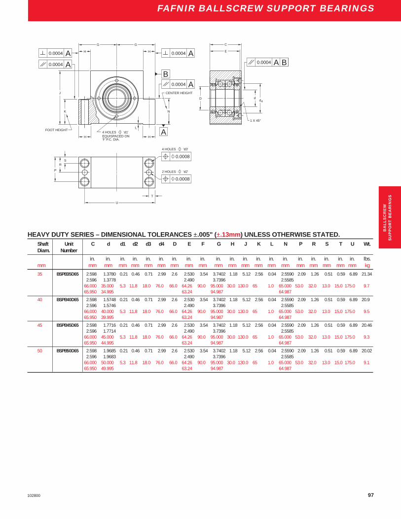
97102800
FAFNIR BALLSCREW SUPPORT BEARINGS
B
AA
4 HOLES 'd1' EQUISPACED ON 'F' P.C. DIA.
G
H
H
A
N
L
CENTER HEIGHT
G
H
K
H
J
A0.0004
FOOT HEIGHT A
dd
4
1 X 45°
A B
C
E
U
T
SR
P
0.0008
4 HOLES 'd3'
2 HOLES 'd2'
D
0.0004 0.0004
0.0004
0.0004
0.0008
HEAVY DUTY SERIES – DIMENSIONAL TOLERANCES ±.005" (±.13mm) UNLESS OTHERWISE STATED.Shaft Unit C d d1 d2 d3 d4 D E F G H J K L N P R S T U Wt.Diam. Number
in. in. in. in. in. in. in. in. in. in. in. in. in. in. in. in. in. in. in. in. lbs.mm mm mm mm mm mm mm mm mm mm mm mm mm mm mm mm mm mm mm mm mm kg
35 BSPB35D65 2.598 1.3780 0.21 0.46 0.71 2.99 2.6 2.530 3.54 3.7402 1.18 5.12 2.56 0.04 2.5590 2.09 1.26 0.51 0.59 6.89 21.342.596 1.3778 2.490 3.7396 2.5585
66.000 35.000 5.3 11.8 18.0 76.0 66.0 64.26 90.0 95.000 30.0 130.0 65 1.0 65.000 53.0 32.0 13.0 15.0 175.0 9.765.950 34.995 63.24 94.987 64.987
40 BSPB40D65 2.598 1.5748 0.21 0.46 0.71 2.99 2.6 2.530 3.54 3.7402 1.18 5.12 2.56 0.04 2.5590 2.09 1.26 0.51 0.59 6.89 20.92.596 1.5746 2.490 3.7396 2.5585
66.000 40.000 5.3 11.8 18.0 76.0 66.0 64.26 90.0 95.000 30.0 130.0 65 1.0 65.000 53.0 32.0 13.0 15.0 175.0 9.565.950 39.995 63.24 94.987 64.987
45 BSPB45D65 2.598 1.7716 0.21 0.46 0.71 2.99 2.6 2.530 3.54 3.7402 1.18 5.12 2.56 0.04 2.5590 2.09 1.26 0.51 0.59 6.89 20.462.596 1.7714 2.490 3.7396 2.5585
66.000 45.000 5.3 11.8 18.0 76.0 66.0 64.26 90.0 95.000 30.0 130.0 65 1.0 65.000 53.0 32.0 13.0 15.0 175.0 9.365.950 44.995 63.24 94.987 64.987
50 BSPB50D65 2.598 1.9685 0.21 0.46 0.71 2.99 2.6 2.530 3.54 3.7402 1.18 5.12 2.56 0.04 2.5590 2.09 1.26 0.51 0.59 6.89 20.022.596 1.9683 2.490 3.7396 2.5585
66.000 50.000 5.3 11.8 18.0 76.0 66.0 64.26 90.0 95.000 30.0 130.0 65 1.0 65.000 53.0 32.0 13.0 15.0 175.0 9.165.950 49.995 63.24 94.987 64.987
BA
LL
SC
RE
WS
UP
PO
RT
BE
AR
ING
S

98 102800
FAFNIR BALLSCREW SUPPORT BEARINGS
STANDARD SERIES – DIMENSIONAL TOLERANCES ± .005" (± .13 MM) UNLESS OTHERWISE STATEDShaft Unit C d d1 d2 d3 d4 D E F G H J K L N P R S T U Wt.Diam. Number
in. in. in. in. in. in. in. in. in. in. in. in. in. in. in. in. in. in. in. in. lbs.mm mm mm mm mm mm mm mm mm mm mm mm mm mm mm mm mm mm mm mm mm kg17 BSPB17Q32 3.031 0.6693 0.17 0.31 0.35 1.42 1.02 2.924 1.67 1.8504 0.67 2.44 1.26 0.04 1.2598 2.68 0.87 0.35 0.33 3.37 5.72
3.030 0.6691 2.864 1.8499 1.259377.000 17.000 4.3 7.8 9.0 36.0 26.0 74.26 42.5 47.000 17 62 32.0 1.0 32.000 68.0 22.0 9.0 8.5 85.5 2.676.950 16.996 72.74 46.987 31.987
20 BSPB20Q32 3.031 0.7874 0.17 0.31 0.35 1.42 1.02 2.924 1.67 1.8504 0.67 2.44 1.26 0.04 1.2598 2.68 0.87 0.35 0.33 3.37 5.53.030 0.7872 2.864 1.8499 1.2593
77.000 20.000 4.3 7.8 9.0 36.0 26.0 74.26 42.5 47.000 17 62 32.0 1.0 32.000 68.0 22.0 9.0 8.5 85.5 2.576.950 19.996 72.74 46.987 31.987
25 BSPB25Q42 3.228 0.9842 0.17 0.39 0.43 1.97 1.57 3.160 2.34 2.4606 0.79 3.35 1.65 0.04 1.6535 2.83 0.98 0.39 0.39 4.53 10.123.226 0.9841 3.100 2.4601 1.6530
82.000 25.000 4.3 9.8 11.0 50.0 40.0 80.26 59.5 62.500 20 85 42.0 1.0 42.000 72.0 25.0 10.0 10.0 115.0 4.681.950 24.995 78.74 62.487 41.987
30 BSPB30Q42 3.228 1.1811 0.17 0.39 0.43 1.97 1.57 3.160 2.34 2.4606 0.79 3.35 1.65 0.04 1.6535 2.83 0.98 0.39 0.39 4.53 9.93.226 1.1809 3.100 2.4601 1.6530
82.000 30.000 4.3 9.8 11.0 50.0 40.0 80.26 59.5 62.500 20 85 42.0 1.0 42.000 72.0 25.0 10.0 10.0 115.0 4.581.950 29.996 78.74 62.487 41.987
35 BSPB35Q50 3.228 1.378 0.17 0.51 0.51 2.36 1.81 3.160 2.62 2.6772 0.81 3.74 1.97 0.04 1.9685 2.83 0.98 0.39 0.39 4.96 13.643.226 1.3778 3.100 2.6767 1.9680
82.000 35.000 4.3 13.0 13.0 60.0 46.0 80.26 66.5 68.000 20.5 95 50.0 1.0 50.000 72.0 25.0 10.0 10.0 126.0 6.281.950 34.995 78.74 67.987 49.987
40 BSPB40Q50 3.228 1.5748 0.17 0.51 0.51 2.36 1.81 3.160 2.62 2.6772 0.81 3.74 1.97 0.04 1.9685 2.83 0.98 0.39 0.39 4.96 13.23.226 1.5746 3.100 2.6767 1.9680
82.000 40.000 4.3 13.0 13.0 60.0 46.0 80.26 66.5 68.000 20.5 95 50.0 1.0 50.000 72.0 25.0 10.0 10.0 126.0 681.950 39.995 78.74 67.987 49.987
BSPB QStandard andHeavy Duty BearingsThe BSPB Q series is similar in design and features to theBSPB D series except MM-BS-QU Quadruplex bearings areused.
Consult our Engineering Department for recommendedshaft and housing fits.

99102800
FAFNIR BALLSCREW SUPPORT BEARINGS
B
A
4 HOLES 'd1' EQUISPACED ON 'F' P.C. DIA.
G
H
H
A
N
L
CENTER HEIGHT
G
H
K
H
J
A
FOOT HEIGHT A
U
T
SR
P
0.0008
4 HOLES 'd3'
2 HOLES 'd2'
A0.0004
C
E
D dd
4
1 X 45°
A B0.0004
0.0004
0.0004
0.0004
0.0008
HEAVY DUTY SERIES – DIMENSIONAL TOLERANCES ± .005" (± .13 MM) UNLESS OTHERWISE STATEDShaft Unit C d d1 d2 d3 d4 D E F G H J K L N P R S T U Wt.Diam. Number
in. in. in. in. in. in. in. in. in. in. in. in. in. in. in. in. in. in. in. in. lbs.mm mm mm mm mm mm mm mm mm mm mm mm mm mm mm mm mm mm mm mm mm kg35 BSPB35Q65 4.173 1.3780 0.21 0.46 0.71 2.99 2.6 4.105 3.54 3.7402 1.18 5.12 2.56 0.04 2.5590 3.66 1.26 0.51 0.59 6.89 34.98
4.171 1.3778 4.045 3.7396 2.5585106.000 35.000 5.3 11.8 18.0 76.0 66.0 104.26 90.0 95.000 30.0 130.0 65.0 1.0 65.000 93.0 32.0 13.0 15.0 175.0 15.9105.950 34.995 102.74 94.987 65.987
40 BSPB40Q65 4.173 1.5748 0.21 0.46 0.71 2.99 2.6 4.105 3.54 3.7402 1.18 5.12 2.56 0.04 2.5590 3.66 1.26 0.51 0.59 6.89 34.544.171 1.5746 4.045 3.7396 2.5585
106.000 40.000 5.3 11.8 18.0 76.0 66.0 104.26 90.0 95.000 30.0 130.0 65.0 1.0 65.000 93.0 32.0 13.0 15.0 175.0 15.7105.950 39.995 102.74 94.987 65.987
45 BSPB45Q65 4.173 1.7716 0.21 0.46 0.71 2.99 2.6 4.105 3.54 3.7402 1.18 5.12 2.56 0.04 2.5590 3.66 1.26 0.51 0.59 6.89 33.884.171 1.7714 4.045 3.7396 2.5585
106.000 45.000 5.3 11.8 18.0 76.0 66.0 104.26 90.0 95.000 30.0 130.0 65.0 1.0 65.000 93.0 32.0 13.0 15.0 175.0 15.4105.950 44.995 102.74 94.987 65.987
50 BSPB50Q65 4.173 1.9685 0.21 0.46 0.71 2.99 2.6 4.105 3.54 3.7402 1.18 5.12 2.56 0.04 2.5590 3.66 1.26 0.51 0.59 6.89 33.224.171 1.9683 4.045 3.7396 2.5585
106.000 50.000 5.3 11.8 18.0 76.0 66.0 104.26 90.0 95.000 30.0 130.0 65.0 1.0 65.000 93.0 32.0 13.0 15.0 175.0 15.1105.950 49.995 102.74 94.987 65.987
BA
LL
SC
RE
WS
UP
PO
RT
BE
AR
ING
S

100 102800
FAFNIR BALLSCREW SUPPORT BEARINGS
FAFNIR BALLSCREW SUPPORT BEARING HOUSED UNITSBearing Bearing
Unit Ref. Set Ref. Unit Ref. Set Ref.
BSBU17D60 MM17BS47DUH BSBU17Q60 MM17BS47QUHBSBU20D60 MM20BS47DUH BSBU20Q60 MM20BS47QUHBSBU25D80 MM25BS62DUH BSBU25Q80 MM25BS62QUHBSBU30D80 MM30BS62DUH BSBU30Q80 MM30BS62QUHBSBU35D90 MM35BS72DUH BSBU35Q90 MM35BS72QUHBSBU40D90 MM40BS72DUH BSBU40Q90 MM40BS72QUHBSBU35D124 MM35BS100DUH BSBU35Q124 MM35BS100QUHBSBU40D124 MM40BS100DUH BSBU40Q124 MM40BS100QUHBSBU45D124 MM45BS100DUH BSBU45Q124 MM45BS100QUHBSBU50D124 MM50BS100DUH BSBU50Q124 MM50BS100QUH
Bearing BearingUnit Ref. Set Ref. Unit Ref. Set Ref.
BSPB17D32 MM17BS47DUH BSPB17Q32 MM17BS47QUHBSPB20D32 MM20BS47DUH BSPB20Q32 MM20BS47QUHBSPB25D42 MM25BS62DUH BSPB25Q42 MM25BS62QUHBSPB30D42 MM30BS62DUH BSPB30Q42 MM30BS62QUHBSPB35D50 MM35BS72DUH BSPB35Q50 MM35BS72QUHBSPB40D50 MM40BS72DUH BSPB40Q50 MM40BS72QUHBSPB35D65 MM35BS100DUH BSPB35Q65 MM35BS100QUHBSPB40D65 MM40BS100DUH BSPB40Q65 MM40BS100QUHBSPB45D65 MM45BS100DUH BSPB45Q65 MM45BS100QUHBSPB50D65 MM50BS100DUH BSPB50Q65 MM50BS100QUH

101102800
FAFNIR BALLSCREW SUPPORT BEARINGS
BA
LL
SC
RE
WS

102 102800

E1102800
EN
GIN
EE
RIN
G
ENGINEERING

E2 102800
ENGINEERING
ForewordWork and tool spindles are the most important toolcomponents of machine tools. Consequently, to reachthe requirements for spindle speed, work accuracy andfinish, selection of the proper size and type of ball bearingsto support these spindles is a critical design problem.
Of all the anti-friction bearing types, superprecision ballbearings have proved to be the best value for the widevariety of bearing applications covering broad ranges ofoperating loads, speeds and lubrication conditions.Duplexed, preloaded, angular-contact bearings with one-piece composition retainers, have excellent capacity andprovide maximum spindle rigidity. These bearings arewidely used in achieving faster speeds, greater accuracy,smoother finishes and higher production rates at minimumcosts.
Many considerations are involved in the choice ofbearings for precision applications. Among those whichinfluence the performance of machine tool spindles are theinternal fit-up and geometry of the bearings, the mountingarrangement, the shaft and housing mounting fits, thebalance and alignment of the rotating parts, and last, butequally important, the lubrication. While many of thesefactors are significant in slow-speed applications, all ofthem must be considered for high-speed spindles.
To minimize deflection under load, shafts for machinetool spindles are designed to have a minimum unsupportedlength and maximum cross-section. For the same reason,spindle housings are designed heavy enough to carry thework load. Their cross-sections are made as uniform aspossible to reduce stress concentration during unevendeflection of the frame due to thermal changes. Inaddition, heavy, well-proportioned housings can functionas sinks to conduct heat away from ball bearings.
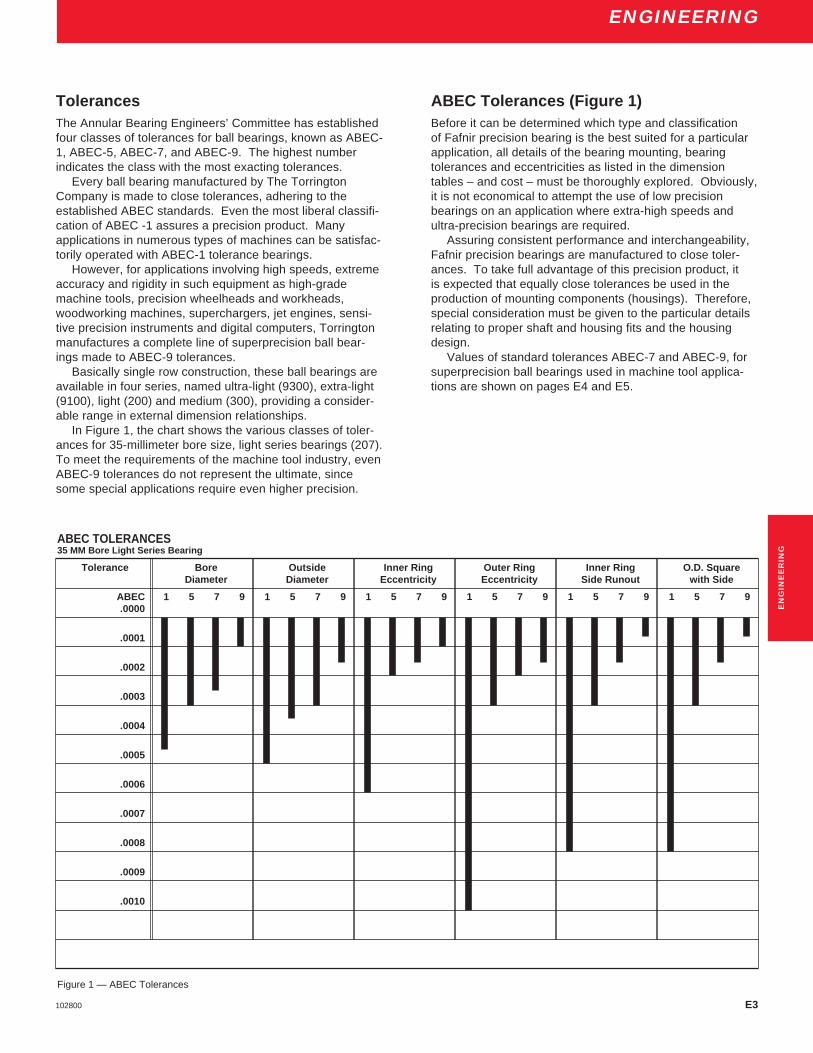
E3102800
ENGINEERING
ABEC TOLERANCES35 MM Bore Light Series Bearing
Tolerance Bore Outside Inner Ring Outer Ring Inner Ring O.D. SquareDiameter Diameter Eccentricity Eccentricity Side Runout with Side
ABEC 1 5 7 9 1 5 7 9 1 5 7 9.0000
.0001
.0002
.0003
.0004
.0005
.0006
.0007
.0008
.0009
.0010
1 5 7 9 1 5 7 9 1 5 7 9
Figure 1 — ABEC Tolerances
TolerancesThe Annular Bearing Engineers’ Committee has establishedfour classes of tolerances for ball bearings, known as ABEC-1, ABEC-5, ABEC-7, and ABEC-9. The highest numberindicates the class with the most exacting tolerances.
Every ball bearing manufactured by The TorringtonCompany is made to close tolerances, adhering to theestablished ABEC standards. Even the most liberal classifi-cation of ABEC -1 assures a precision product. Manyapplications in numerous types of machines can be satisfac-torily operated with ABEC-1 tolerance bearings.
However, for applications involving high speeds, extremeaccuracy and rigidity in such equipment as high-grademachine tools, precision wheelheads and workheads,woodworking machines, superchargers, jet engines, sensi-tive precision instruments and digital computers, Torringtonmanufactures a complete line of superprecision ball bear-ings made to ABEC-9 tolerances.
Basically single row construction, these ball bearings areavailable in four series, named ultra-light (9300), extra-light(9100), light (200) and medium (300), providing a consider-able range in external dimension relationships.
In Figure 1, the chart shows the various classes of toler-ances for 35-millimeter bore size, light series bearings (207).To meet the requirements of the machine tool industry, evenABEC-9 tolerances do not represent the ultimate, sincesome special applications require even higher precision.
ABEC Tolerances (Figure 1)Before it can be determined which type and classificationof Fafnir precision bearing is the best suited for a particularapplication, all details of the bearing mounting, bearingtolerances and eccentricities as listed in the dimensiontables – and cost – must be thoroughly explored. Obviously,it is not economical to attempt the use of low precisionbearings on an application where extra-high speeds andultra-precision bearings are required.
Assuring consistent performance and interchangeability,Fafnir precision bearings are manufactured to close toler-ances. To take full advantage of this precision product, itis expected that equally close tolerances be used in theproduction of mounting components (housings). Therefore,special consideration must be given to the particular detailsrelating to proper shaft and housing fits and the housingdesign.
Values of standard tolerances ABEC-7 and ABEC-9, forsuperprecision ball bearings used in machine tool applica-tions are shown on pages E4 and E5.
EN
GIN
EE
RIN
G

E4 102800
ENGINEERING
STANDARD ABEC TOLERANCES – INNER RINGAll tolerances in number of ten-thousandths inches (.0001") and micrometers ( µm)
d ∆dmp VBs Kia Sd Sia ∆Bs & ∆CsBearing Bore Bore Diameter(1) Width Variation Raceway Face Runout Raceway Width
(Parallelism) Radial Runout With Bore Axial Runout Inner & Outer Rings+.0000",+.000mm (Squareness) +.0000",+.000mm
to minus to minusMMV MMV MMV MMV MMVABEC ABEC ABEC ABEC ABEC ABEC ABEC ABEC ABEC ABEC ABEC
7 9 7 9 7 9 7 9 7 9 7,9
Over Incl. inch inch inch inch inch inch inch inch inch inch inchmm mm µm µm µm µm µm µm µm µm µm µm µm
0 10 -1 1⁄2 -1 1 1⁄ 2 1 1⁄ 2 1 1⁄ 2 1 1⁄ 2 0.0016-4 -2 1⁄ 2 2.5 1 1⁄ 2 2 1⁄ 2 1 1⁄ 2 3 1 1⁄ 2 3 1 1⁄ 2 0.04
10 18 -1 1⁄2 -1 1 1⁄ 2 1 1⁄2 1 1⁄ 2 1 1⁄ 2 0.0031-4 -2 1⁄ 2 2.5 1 1⁄ 2 2 1⁄ 2 1 1⁄ 2 3 1 1⁄ 2 3 1 1⁄ 2 0.08
18 30 -2 -1 1 1⁄ 2 1 1 1 1⁄2 1⁄ 2 1 1⁄2 1 0.0047-5 -2 1⁄ 2 2.5 1 1⁄ 2 3 2 1⁄ 2 4 1 1⁄ 2 4 2 1⁄ 2 0.12
30 50 -2 1⁄2 -1 1 1⁄ 2 1 1⁄ 2 1 1 1⁄2 1⁄ 2 1 1⁄2 1 0.0047-6 -2 1⁄ 2 3 1 1⁄ 2 4 2 1⁄ 2 4 1 1⁄ 2 4 2 1⁄ 2 0.12
50 80 -3 -1 1⁄ 2 1 1⁄ 2 1⁄ 2 1 1⁄ 2 1 2 1⁄ 2 2 1 0.0059-7 -4 4 1 1⁄ 2 4 2 1⁄ 2 5 1 1⁄ 2 5 2 1⁄ 2 0.15
80 120 -3 -2 1 1⁄ 2 1 2 1 2 1 2 1 0.0079-8 -5 4 2 1⁄ 2 5 2 1⁄ 2 5 2 1⁄ 2 5 2 1⁄ 2 0.20
120 150 -4 -3 2 1 2 1 2 1⁄2 1 3 1 0.0098-10 -7 5 2 1⁄ 2 5 2 1⁄ 2 6 2 1⁄ 2 7 2 1⁄ 2 0.25
150 180 -4 -3 2 1 1⁄ 2 2 1⁄ 2 2 2 1⁄2 1 1⁄ 2 3 2 0.0098-10 -7 5 4 6 5 6 4 7 5 0.25
180 250 -4 1⁄2 -3 2 1⁄ 2 2 3 2 3 2 3 2 0.0118-12 -8 6 5 8 5 7 5 8 5 0.30
(1) dMIN and dMAX (the smallest single diameter and the largest single diameter of a bore in a single radial plane, respectively) may fall outsidelimits shown.dMIN + dMAX in a single radial plane must be within bore diameter tabulated. For further details see ABMA Standard 20 and Standard 4. 2
ABMA/ISO Symbols – Inner Ring∆dmp Single plane mean bore diameter deviation from the
basic bore diameter,i.e.,bore tolerance.
Kia Radial runout of assembled bearing inner ring, i.e.,radial runout of raceway.
VBs Inner ring width variation, i.e. parallelism.
Sd Inner ring reference face runout with bore, i.e.,squareness – bore to face.
Sia Axial runout af assembled bearing inner ring, i.e.,lateral (axial) runout of raceway.
∆Bs Single inner ring width deviation from basic, i.e.,width tolerance.
Standard Tolerances
Inner Ring ABEC – 7,9—ISO P4, P2Depending upon the requirement, various degrees of bearingaccuracy may be required.
Among the tolerance classes, ABEC-1 applies to ballbearings for normal usage. The other classes ABEC-3,5,7,9 apply to ball bearings of increased precision asrequired.
Values of tolerances ABEC-7 and ABEC-9 forsuperprecision ball bearings are shown below.
Width Tolerances:The width tolerances for individual inner and outer rings areshown in the above table but, to allow for the face grindingon two bearings for various preloads, the total widthtolerances of duplex pairs of bearings are as shown.
Preloaded Duplex Set Width ToleranceNominal bore WidthMillimeters Tolerance
Over Inclusive Maximum Minimum
0 200 .000" .010".00mm .25mm

E5102800
ENGINEERING
STANDARD ABEC TOLERANCES – OUTER RINGAll tolerances in number of ten-thousandths inches (.0001") and micrometers ( µm)
D ∆Dmp VCs Kea Sea SDBearing Outside Diameter(1) Width Variation Raceway Raceway Outside Diameter
O.D. (Parallelism) Radial Runout Axial Runout Runout With Face+.0000",+.000mm (Squareness)
to minusMMV MMV MMV MMV MMVABEC ABEC ABEC ABEC ABEC ABEC ABEC ABEC ABEC ABEC
7 9 7 9 7 9 7 9 7 9
Over Incl. inch inch inch inch inch inch inch inch inch inchmm mm µm µm µm µm µm µm µm µm µm µm
0 18 -1 1/2 -1 1 1/2 1 1/2 2 1/2 1 1/2 1/2-4 -2 1⁄2 2 1⁄2 1 1⁄2 3 1 1⁄2 5 1 1⁄2 4 1 1⁄2
18 30 -2 -1 1/2 1 1/2 1 1/2 1 2 1 1 1/2 1/2-5 -4 2 1⁄2 1 1⁄2 4 2 1⁄2 5 2 1⁄2 4 1 1⁄2
30 50 -2 1/2 -1 1/2 1 1/2 2 1 2 1 1 1/2 1/2-6 -4 2 1⁄2 1 1⁄2 5 2 1⁄2 5 2 1⁄2 4 1 1⁄2
50 80 -3 -1 1/2 1 1/2 2 1 1/2 2 1 1/2 1 1/2 1/2-7 -4 3 1 1⁄2 5 4 5 4 4 1 1⁄2
80 120 -3 -2 1 1/2 1 2 1/2 2 2 1/2 2 2 1-8 -5 4 2 1⁄2 6 5 6 5 5 2 1⁄2
120 150 -3 1/2 -2 2 1 3 2 3 2 2 1-9 -5 5 2 1⁄2 7 5 7 5 5 2 1⁄2
150 180 -4 -3 2 1 3 2 3 2 2 1-10 -7 5 2 1⁄2 8 5 8 5 5 2 1⁄2
180 250 -4 1/2 -3 3 1 1/2 4 3 4 3 3 1 1/2-11 -8 7 4 10 7 10 7 7 4
250 315 -5 -3 3 2 4 1/2 3 4 3 3 2-13 -8 7 5 11 7 10 7 8 5
315 400 -6 -4 3 3 5 3 5 3 4 3-15 -10 8 7 13 8 13 8 10 7
(1) DMIN and DMAX (the smallest single diameter and the largest single diameter of a O.D. in a single radial plane, respectively) may fall outsidelimits shown.DMIN + DMAX in a single radial plane must be within O.D. diameter tabulated. For further details see ABMA Standard 20 and Standard 4. 2
Standard Tolerances
Outer Ring ABEC – 7,9—ISO P4, P2Depending upon the requirement, various degrees of bearingaccuracy may be required.
Among the tolerance classes, ABEC-1 applies to ballbearings for normal usage. The other classes ABEC-3,5,7,9apply to ball bearings of increased precision as required.
Values of tolerances ABEC-7 and ABEC-9 forsuperprecision ball bearings are shown below.
ABMA/ISO Symbols – Outer Ring
∆Dmp Single plane mean outside diameter deviation frombasic outside diameter,i.e.,O.D. tolerance.
Kea Radial runout of assembled bearing outer ring, i.e.,radial runout of raceway.
VCs Outer ring width variation, i.e. parallelism.
SD Outside cylindrical surface runout with outer ringrefernece face, i.e., squareness O.D. to face.
Sea Axial runout af assembled bearing outer ring, i.e.lateral (axial) runout of raceway.
∆Cs Single outer ring width deviation from basic, i.e.,width tolerance.
EN
GIN
EE
RIN
G
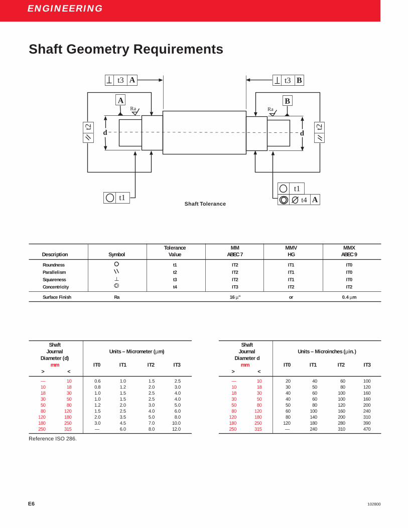
E6 102800
ENGINEERING
Tolerance MM MMV MMXDescription Symbol Value ABEC 7 HG ABEC 9
Roundness t1 IT2 IT1 IT0
Parallelism t2 IT2 IT1 IT0
Squareness t3 IT2 IT1 IT0
Concentricity t4 IT3 IT2 IT2
Surface Finish Ra 16 µ" or 0.4 µm
Shaft Geometry Requirements
Shaft ShaftJournal Units – Micrometer (µm) Journal Units – Microinches (µin.)
Diameter (d) Diameter dmm IT0 IT1 IT2 IT3 mm IT0 IT1 IT2 IT3
> < > <
— 10 0.6 1.0 1.5 2.5 — 10 20 40 60 10010 18 0.8 1.2 2.0 3.0 10 18 30 50 80 12018 30 1.0 1.5 2.5 4.0 18 30 40 60 100 16030 50 1.0 1.5 2.5 4.0 30 50 40 60 100 16050 80 1.2 2.0 3.0 5.0 50 80 50 80 120 20080 120 1.5 2.5 4.0 6.0 80 120 60 100 160 240
120 180 2.0 3.5 5.0 8.0 120 180 80 140 200 310180 250 3.0 4.5 7.0 10.0 180 250 120 180 280 390250 315 — 6.0 8.0 12.0 250 315 — 240 310 470
Reference ISO 286.
Shaft Tolerance
t3 B
t2
BRa
t1At4t1
t2
A
d
Ra
t3 A
d
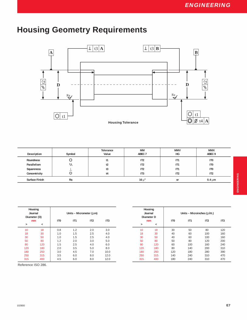
E7102800
ENGINEERING
Housing HousingJournal Units – Micrometer (µm) Journal Units – Microinches (µin.)
Diameter (D) Diameter Dmm IT0 IT1 IT2 IT3 mm IT0 IT1 IT2 IT3
> < > <
10 18 0.8 1.2 2.0 3.0 10 18 30 50 80 12018 30 1.0 1.5 2.5 4.0 18 30 40 60 100 16030 50 1.0 1.5 2.5 4.0 30 50 40 60 100 16050 80 1.2 2.0 3.0 5.0 50 80 50 80 120 20080 120 1.5 2.5 4.0 6.0 80 120 60 100 160 240
120 180 2.0 3.5 5.0 8.0 120 180 80 140 200 310180 250 3.0 4.5 7.0 10.0 180 250 120 180 280 390250 315 3.5 6.0 8.0 12.0 250 315 140 240 310 470315 400 4.5 6.0 8.0 12.0 315 400 180 240 310 470
Reference ISO 286.
Tolerance MM MMV MMXDescription Symbol Value ABEC 7 HG ABEC 9
Roundness t1 IT2 IT1 IT0
Parallelism t2 IT2 IT1 IT0
Squareness t3 IT2 IT1 IT0
Concentricity t4 IT3 IT2 IT2
Surface Finish Ra 16 µ" or 0.4 µm
EN
GIN
EE
RIN
G
t1
t3 Bt3 At2
A
D
Ra
t2
B
D
Ra
t1
At4Housing Tolerance
Housing Geometry Requirements

E8 102800
ENGINEERING
* SHAFT MOUNTING FITS – ABEC – 7 (ISO P4)Bearing Bearing Bore Rotating Shaft
Bore Diameter Shaft Diameter Mounting FitsNumber
max. min. max. min. min. max. min. max. loose tight loose tightinch inch mm mm inch inch mm mm inch inch mm mm
00 0.3937 0.39355 10 9.996 0.3935 0.3937 9.995 10.000 0.0002 0.00015 0.005 0.00401 0.4724 0.47225 12 11.996 0.4722 0.4724 11.995 12.000 0.0002 0.00015 0.005 0.00402 0.5906 0.59045 15 14.996 0.5904 0.5906 14.995 15.000 0.0002 0.00015 0.005 0.00403 0.6693 0.66915 17 16.996 0.6691 0.6693 16.995 17.000 0.0002 0.00015 0.005 0.00404 0.7874 0.78720 20 19.995 0.7872 0.7874 19.995 20.000 0.0002 0.00020 0.005 0.005
05 0.9843 0.98410 25 24.995 0.9841 0.9843 24.995 25.000 0.0002 0.00020 0.005 0.00506 1.1811 1.18090 30 29.995 1.1809 1.1811 29.995 30.000 0.0002 0.00020 0.005 0.00507 1.3780 1.37775 35 34.994 1.3778 1.3780 34.995 35.000 0.0002 0.00025 0.005 0.00608 1.5748 1.57455 40 39.994 1.5746 1.5748 39.995 40.000 0.0002 0.00025 0.005 0.00609 1.7717 1.77145 45 44.994 1.7715 1.7717 44.995 45.000 0.0002 0.00025 0.005 0.006
10 1.9685 1.96825 50 49.994 1.9683 1.9685 49.995 50.000 0.0002 0.00025 0.005 0.00611 2.1654 2.16510 55 54.993 2.1652 2.1654 54.995 55.000 0.0002 0.00030 0.005 0.00712 2.3622 2.36190 60 59.993 2.3620 2.3622 59.995 60.000 0.0002 0.00030 0.005 0.00713 2.5591 2.55880 65 64.993 2.5589 2.5591 64.995 65.000 0.0002 0.00030 0.005 0.00714 2.7559 2.75560 70 69.993 2.7557 2.7559 69.995 70.000 0.0002 0.00030 0.005 0.007
15 2.9528 2.95250 75 74.993 2.9526 2.9530 74.995 75.005 0.0002 0.00050 0.005 0.01216 3.1496 3.14930 80 79.993 3.1494 3.1498 79.995 80.005 0.0002 0.00050 0.005 0.01217 3.3465 3.34620 85 84.992 3.3463 3.3467 84.995 85.005 0.0002 0.00050 0.005 0.01218 3.5433 3.5430 90 89.992 3.5431 3.5435 89.995 90.005 0.0002 0.00050 0.005 0.01319 3.7402 3.73990 95 94.992 3.7400 3.7404 94.995 95.005 0.0002 0.00050 0.005 0.013
* Over 750,000 dN, consult with Torrington Engineering Department.
Recommended Spindle Shaft Tolerances

E9102800
ENGINEERING
EN
GIN
EE
RIN
G
* SHAFT MOUNTING FITS – ABEC – 7 (ISO P4)Bearing Bearing Bore Rotating Shaft
Bore Diameter Shaft Diameter Mounting FitsNumber
max. min. max. min. min. max. min. max. loose tight loose tightinch inch mm mm inch inch mm mm inch inch mm mm
20 3.9370 3.93670 100 99.992 3.9368 3.9372 99.995 100.005 0.0002 0.0005 0.005 0.01321 4.1339 4.13360 105 104.992 4.1337 4.1341 104.995 105.005 0.0002 0.0005 0.005 0.01322 4.3307 4.33040 110 109.992 4.3305 4.3309 109.995 110.005 0.0002 0.0005 0.005 0.01324 4.7244 4.72410 120 119.992 4.7242 4.7246 119.995 120.005 0.0002 0.0005 0.005 0.01326 5.1181 5.11770 130 129.990 5.1179 5.1183 129.995 130.005 0.0002 0.0006 0.005 0.015
28 5.5118 5.51140 140 139.990 5.5116 5.5120 139.995 140.005 0.0002 0.0006 0.005 0.01530 5.9055 5.90510 150 149.990 5.9053 5.9057 149.995 150.005 0.0002 0.0006 0.005 0.01532 6.2992 6.29880 160 159.990 6.2990 6.2994 159.995 160.005 0.0002 0.0006 0.005 0.01534 6.6929 6.69250 170 169.990 6.6927 6.6931 169.995 170.005 0.0002 0.0006 0.005 0.01536 7.0866 7.08620 180 179.990 7.0863 7.0869 179.993 180.008 0.0003 0.0007 0.007 0.018
38 7.4803 7.47985 190 189.990 7.4800 7.4806 189.993 190.008 0.0003 0.0008 0.007 0.01940 7.8740 7.87355 200 199.990 7.8737 7.8743 199.993 200.008 0.0003 0.0008 0.007 0.019
* Over 750,000 dN, consult with Torrington Engineering Department.
E10 102800
ENGINEERING
HOUSING MOUNTING FITS (FIXED) – ABEC – 7 (ISO P4)
Bearing O.D. Stationary HousingDiameter
Housing Bore Mounting Fits
max. min. min. max. tight loose
inch inch inch inch inch inchmm mm mm mm mm mm
0.8661 0.8659 0.8661 0.8663 0.0000 0.000422 21.995 22 22.005 0.000 0.010
0.9449 0.9447 0.9449 0.9451 0.0000 0.000424 23.995 24 24.005 0.000 0.010
1.0236 1.0234 1.0236 1.0238 0.0000 0.000426 25.995 26 26.005 0.000 0.010
1.1024 1.1022 1.1024 1.1026 0.0000 0.000428 27.995 28 28.005 0.000 0.010
1.1811 1.1809 1.1811 1.1813 0.0000 0.000430 29.995 30 30.005 0.000 0.010
1.2598 1.25955 1.2598 1.2600 0.0000 0.0004532 31.994 32 32.005 0.000 0.011
1.3780 1.37775 1.3780 1.3783 0.0000 0.000535 34.994 35 35.006 0.000 0.012
1.4567 1.45645 1.4567 1.4570 0.0000 0.000537 36.994 37 37.006 0.000 0.012
1.5748 1.57455 1.5748 1.5751 0.0000 0.000540 39.994 40 40.006 0.000 0.012
1.6535 1.65325 1.6535 1.6538 0.0000 0.000542 41.994 42 42.006 0.000 0.012
1.8504 1.85015 1.8504 1.8507 0.0000 0.000547 46.994 47 47.006 0.000 0.012
2.0472 2.0469 2.0472 2.0475 0.0000 0.0005552 51.993 52 52.006 0.000 0.013
2.1654 2.1651 2.1654 2.1657 0.0000 0.000655 54.993 55 55.008 0.000 0.015
2.4409 2.4406 2.4409 2.4412 0.0000 0.000662 61.993 62 62.008 0.000 0.015
2.6772 2.6769 2.6772 2.6775 0.0000 0.000668 67.993 68 68.008 0.000 0.015
2.8346 2.8343 2.8346 2.8349 0.0000 0.000672 71.993 72 72.008 0.000 0.015
Recommended Spindle Housing Tolerances

E11102800
ENGINEERING
HOUSING MOUNTING FITS (FIXED) – ABEC – 7 (ISO P4)
Bearing O.D. Stationary HousingDiameter
Housing Bore Mounting Fits
max. min. min. max. tight loose
inch inch inch inch inch inchmm mm mm mm mm mm
2.9528 2.9525 2.9528 2.9531 0.0000 0.000675 74.993 75 75.008 0.000 0.015
3.1496 3.1493 3.1496 3.1499 0.0000 0.000680 79.993 80 80.008 0.000 0.015
3.3465 3.3462 3.3465 3.3468 0.0000 0.000685 84.992 85 85.008 0.000 0.016
3.5433 3.543 3.5433 3.5436 0.0000 0.000690 89.992 90 90.008 0.000 0.016
3.7402 3.7399 3.7402 3.7405 0.0000 0.000695 94.992 95 95.008 0.000 0.016
3.9370 3.9367 3.9370 3.9373 0.0000 0.0006100 99.992 100 100.008 0.000 0.016
4.1339 4.1336 4.1339 4.1342 0.0000 0.0006105 104.992 105 105.008 0.000 0.016
4.3307 4.3304 4.3307 4.3310 0.0000 0.0006110 109.992 110 110.008 0.000 0.016
4.5276 4.5273 4.5276 4.5279 0.0000 0.0006115 114.992 115 115.008 0.000 0.016
4.7244 4.7241 4.7244 4.7247 0.0000 0.0006120 119.992 120 120.008 0.000 0.016
4.9213 4.92095 4.9213 4.9216 0.0000 0.0007125 124.991 125 125.008 0.000 0.017
5.1181 5.11775 5.1181 5.1185 0.0000 0.0007130 129.991 130 130.009 0.000 0.018
5.5118 5.51145 5.5118 5.5122 0.0000 0.0007140 139.991 140 140.009 0.000 0.018
5.7087 5.70835 5.7087 5.7091 0.0000 0.0007145 144.991 145 145.009 0.000 0.018
5.9055 5.90515 5.9055 5.9059 0.0000 0.0007150 149.991 150 150.009 0.000 0.018
6.2992 6.2988 6.2992 6.2996 0.0000 0.0008160 159.990 160 160.009 0.000 0.0219
EN
GIN
EE
RIN
G

E12 102800
ENGINEERING
HOUSING MOUNTING FITS (FIXED) – ABEC – 7 (ISO P4)Bearing O.D. Stationary Housing
DiameterHousing Bore Mounting Fits
max. min. min. max. tight loose
inch inch inch inch inch inchmm mm mm mm mm mm
6.4961 6.4957 6.4961 6.4965 0.0000 0.0008165 164.990 165 165.010 0.000 0.020
6.6929 6.6925 6.6929 6.6933 0.0000 0.0008170 169.990 170 170.010 0.000 0.020
7.0866 7.0862 7.0866 7.0870 0.0000 0.0008180 179.990 180 180.010 0.000 0.020
7.4803 7.47985 7.4803 7.4807 0.0000 0.0008190 189.989 190 190.010 0.000 0.021
7.8740 7.87355 7.8740 7.8745 0.0000 0.0009200 199.989 200 200.011 0.000 0.022
8.2677 8.26725 8.2677 8.2682 0.0000 0.0009210 209.989 210 210.011 0.000 0.022
8.4646 8.46415 8.4646 8.4651 0.0000 0.0009215 214.989 215 215.011 0.000 0.022
8.8583 8.85785 8.8583 8.8588 0.0000 0.0009225 224.989 225 225.011 0.000 0.022
9.0551 9.05465 9.0551 9.0556 0.0000 0.0009230 229.989 230 230.011 0.000 0.022
9.4488 9.44835 9.4488 9.4493 0.0000 0.0009240 239.989 240 240.011 0.000 0.022
10.2362 10.2357 10.2362 10.2367 0.0000 0.0010260 259.987 260 260.011 0.000 0.024
10.6299 10.6294 10.6299 10.6304 0.0000 0.0010270 269.987 270 270.013 0.000 0.026
11.0236 11.0231 11.0236 11.0241 0.0000 0.0010280 279.987 280 280.013 0.000 0.026
12.2047 12.2042 12.2047 12.2052 0.0000 0.0010310 309.987 310 310.013 0.000 0.026
Recommended Spindle Housing Tolerances

E13102800
ENGINEERING
HOUSING MOUNTING FITS (FLOAT) – ABEC – 7 (ISO P4)Bearing O.D. Stationary Housing
DiameterHousing Bore Housing Clearance
max. min. max. min. max. min.
inch inch inch inch inch inchmm mm mm mm mm mm
0.8661 0.8659 0.8665 0.8663 0.0006 0.000222 21.995 22.010 22.005 0.015 0.005
0.9449 0.9447 0.9453 0.9451 0.0006 0.000224 23.995 24.010 24.005 0.015 0.005
1.0236 1.0234 1.0240 1.0238 0.0006 0.000226 25.995 26.010 26.005 0.015 0.005
1.1024 1.1022 1.1028 1.1026 0.0006 0.000228 27.995 28.010 28.005 0.015 0.005
1.1811 1.1809 1.1815 1.1813 0.0006 0.000230 29.995 30.010 30.005 0.015 0.005
1.2598 1.2596 1.2602 1.2600 0.0007 0.000232 31.994 32.010 32.005 0.016 0.005
1.3780 1.3778 1.3784 1.3782 0.0007 0.000235 34.994 35.010 35.005 0.016 0.005
1.4567 1.4565 1.4571 1.4569 0.0007 0.000237 36.994 37.010 37.005 0.016 0.005
1.5748 1.5746 1.5752 1.5750 0.0007 0.000240 39.994 40.010 40.005 0.016 0.005
1.6535 1.6533 1.6539 1.6537 0.0007 0.000242 41.994 42.010 42.005 0.016 0.005
1.8504 1.8502 1.8509 1.8507 0.0008 0.000347 46.994 47.012 47.007 0.018 0.007
2.0472 2.0469 2.0477 2.0475 0.0008 0.000352 51.993 52.012 52.007 0.019 0.007
2.1654 2.1651 2.1659 2.1657 0.0008 0.000355 54.993 55.012 55.007 0.019 0.007
2.4409 2.4406 2.4414 2.4412 0.0008 0.000362 61.993 62.012 62.007 0.019 0.007
2.6772 2.6769 2.6777 2.6775 0.0008 0.000368 67.993 68.012 68.007 0.019 0.007
2.8346 2.8343 2.8351 2.8349 0.0008 0.000372 71.993 72.0112 72.007 0.019 0.007
EN
GIN
EE
RIN
G
E14 102800
ENGINEERING
Recommended Spindle Housing Tolerances
HOUSING MOUNTING FITS (FLOAT) – ABEC – 7 (ISO P4)Bearing O.D. Stationary Housing
DiameterHousing Bore Housing Clearance
max. min. max. min. max. min.
inch inch inch inch inch inchmm mm mm mm mm mm
2.9528 2.9525 2.9533 2.9531 0.0008 0.000375 74.992 75.014 75.009 0.022 0.009
3.1496 3.1493 3.1501 3.1499 0.0008 0.000380 79.992 80.012 80.008 0.020 0.008
3.3465 3.3462 3.3471 3.3468 0.0009 0.000385 84.992 85.016 85.009 0.024 0.009
3.5433 3.5430 3.5439 3.5436 0.0009 0.000390 89.992 90.015 90.007 0.023 0.007
3.7402 3.7399 3.7408 3.7405 0.0009 0.000395 94.992 95.016 95.009 0.024 0.009
3.9370 3.9367 3.9377 3.9374 0.001 0.0004100 99.992 100.018 100.010 0.025 0.010
4.1339 4.1336 4.1346 4.1343 0.001 0.0004105 104.992 105.019 105.011 0.026 0.011
4.3307 4.3304 4.3314 4.3311 0.001 0.0004110 109.992 110.018 110.010 0.025 0.010
4.5276 4.5273 4.5283 4.5280 0.001 0.0004115 114.992 115.019 115.011 0.026 0.010
4.7244 4.7241 4.7251 4.7248 0.001 0.0004120 119.992 120.018 120.010 0.025 0.010
4.9213 4.9210 4.9221 4.9217 0.0012 0.0004125 124.991 125.021 125.011 0.030 0.011
5.1181 5.1177 5.1189 5.1185 0.0011 0.0004130 129.991 130.020 130.010 0.029 0.010
5.5118 5.5115 5.5126 5.5122 0.0011 0.0004140 139.991 140.020 140.010 0.029 0.010
5.9055 5.9051 5.7095 5.7091 0.0011 0.0004145 144.991 145.021 145.011 0.030 0.011
6.2992 6.2988 5.9064 5.9060 0.0012 0.0005150 149.991 150.023 150.012 0.032 0.012
6.6929 6.6925 6.3001 6.2997 0.0013 0.0005160 159.989 160.022 160.012 0.033 0.012
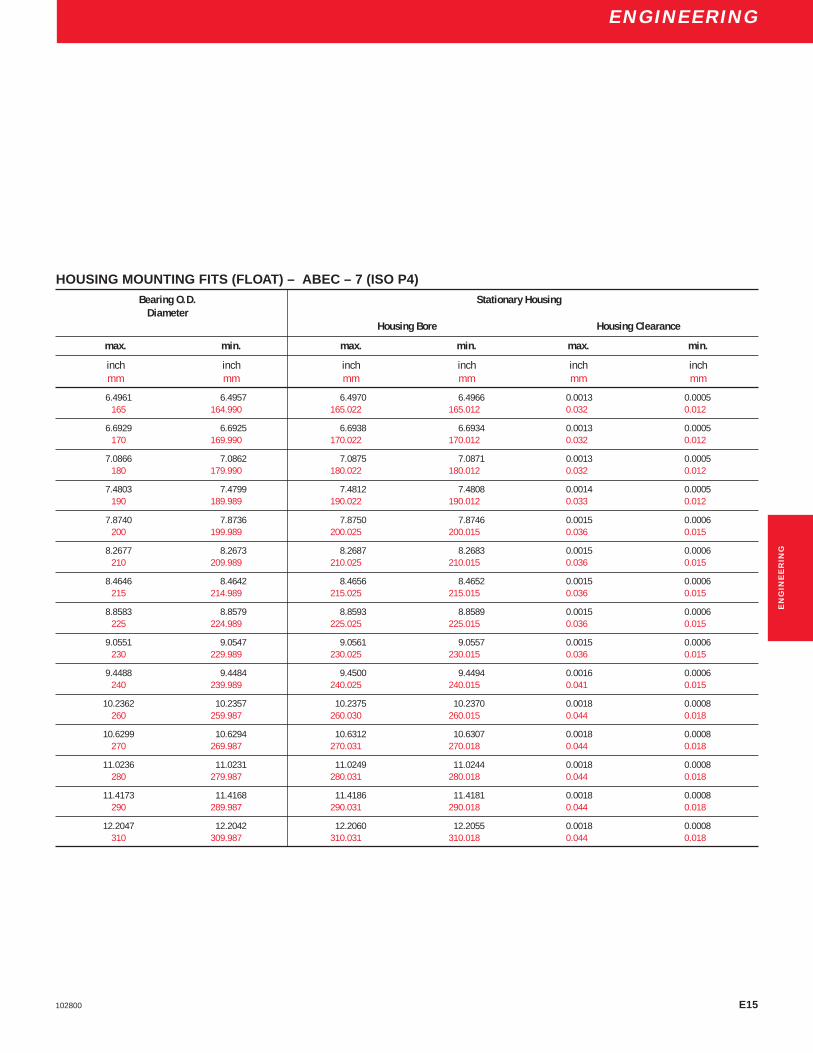
E15102800
ENGINEERING
HOUSING MOUNTING FITS (FLOAT) – ABEC – 7 (ISO P4)Bearing O.D. Stationary Housing
DiameterHousing Bore Housing Clearance
max. min. max. min. max. min.
inch inch inch inch inch inchmm mm mm mm mm mm
6.4961 6.4957 6.4970 6.4966 0.0013 0.0005165 164.990 165.022 165.012 0.032 0.012
6.6929 6.6925 6.6938 6.6934 0.0013 0.0005170 169.990 170.022 170.012 0.032 0.012
7.0866 7.0862 7.0875 7.0871 0.0013 0.0005180 179.990 180.022 180.012 0.032 0.012
7.4803 7.4799 7.4812 7.4808 0.0014 0.0005190 189.989 190.022 190.012 0.033 0.012
7.8740 7.8736 7.8750 7.8746 0.0015 0.0006200 199.989 200.025 200.015 0.036 0.015
8.2677 8.2673 8.2687 8.2683 0.0015 0.0006210 209.989 210.025 210.015 0.036 0.015
8.4646 8.4642 8.4656 8.4652 0.0015 0.0006215 214.989 215.025 215.015 0.036 0.015
8.8583 8.8579 8.8593 8.8589 0.0015 0.0006225 224.989 225.025 225.015 0.036 0.015
9.0551 9.0547 9.0561 9.0557 0.0015 0.0006230 229.989 230.025 230.015 0.036 0.015
9.4488 9.4484 9.4500 9.4494 0.0016 0.0006240 239.989 240.025 240.015 0.041 0.015
10.2362 10.2357 10.2375 10.2370 0.0018 0.0008260 259.987 260.030 260.015 0.044 0.018
10.6299 10.6294 10.6312 10.6307 0.0018 0.0008270 269.987 270.031 270.018 0.044 0.018
11.0236 11.0231 11.0249 11.0244 0.0018 0.0008280 279.987 280.031 280.018 0.044 0.018
11.4173 11.4168 11.4186 11.4181 0.0018 0.0008290 289.987 290.031 290.018 0.044 0.018
12.2047 12.2042 12.2060 12.2055 0.0018 0.0008310 309.987 310.031 310.018 0.044 0.018
EN
GIN
EE
RIN
G
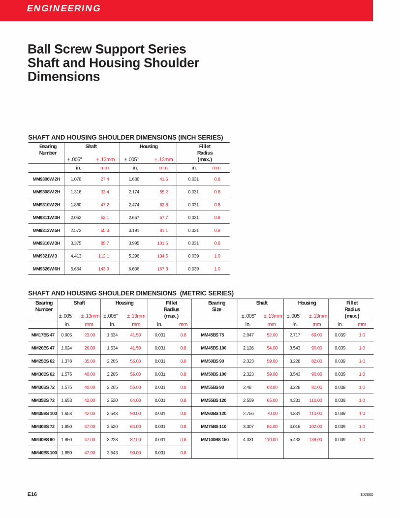
E16 102800
ENGINEERING
Bearing Shaft Housing FilletNumber Radius
± .005" ± .13mm ±.005" ± .13mm (max.)
in. mm in. mm in. mm
MM9306WI2H 1.078 27.4 1.636 41.6 0.031 0.8
MM9308WI2H 1.316 33.4 2.174 55.2 0.031 0.8
MM9310WI2H 1.860 47.2 2.474 62.8 0.031 0.8
MM9311WI3H 2.052 52.1 2.667 67.7 0.031 0.8
MM9313WI5H 2.572 65.3 3.191 81.1 0.031 0.8
MM9316WI3H 3.375 85.7 3.995 101.5 0.031 0.8
MM9321WI3 4.413 112.1 5.296 134.5 0.039 1.0
MM9326WI6H 5.664 143.9 6.606 167.8 0.039 1.0
Bearing Shaft Housing Fillet Bearing Shaft Housing FilletNumber Radius Size Radius
± .005" ± .13mm ± .005" ± .13mm (max.) ± .005" ± .13mm ± .005" ± .13mm (max.)
in. mm in. mm in. mm in. mm in. mm in. mm
MM17BS 47 0.905 23.00 1.634 41.50 0.031 0.8 MM45BS 75 2.047 52.00 2.717 69.00 0.039 1.0
MM20BS 47 1.024 26.00 1.634 41.50 0.031 0.8 MM45BS 100 2.126 54.00 3.543 90.00 0.039 1.0
MM25BS 62 1.378 35.00 2.205 56.00 0.031 0.8 MM50BS 90 2.323 59.00 3.228 82.00 0.039 1.0
MM30BS 62 1.575 40.00 2.205 56.00 0.031 0.8 MM50BS 100 2.323 59.00 3.543 90.00 0.039 1.0
MM30BS 72 1.575 40.00 2.205 56.00 0.031 0.8 MM55BS 90 2.48 63.00 3.228 82.00 0.039 1.0
MM35BS 72 1.653 42.00 2.520 64.00 0.031 0.8 MM55BS 120 2.559 65.00 4.331 110.00 0.039 1.0
MM35BS 100 1.653 42.00 3.543 90.00 0.031 0.8 MM60BS 120 2.756 70.00 4.331 110.00 0.039 1.0
MM40BS 72 1.850 47.00 2.520 64.00 0.031 0.8 MM75BS 110 3.307 84.00 4.016 102.00 0.039 1.0
MM40BS 90 1.850 47.00 3.228 82.00 0.031 0.8 MM100BS 150 4.331 110.00 5.433 138.00 0.039 1.0
MM40BS 100 1.850 47.00 3.543 90.00 0.031 0.8
Ball Screw Support SeriesShaft and Housing ShoulderDimensions
SHAFT AND HOUSING SHOULDER DIMENSIONS (INCH SERIES)
SHAFT AND HOUSING SHOULDER DIMENSIONS (METRIC SERIES)

E17102800
ENGINEERING
ULTRA-LIGHT 9300 SERIES EXTRA LIGHT 9100 SERIESBasic Shoulder Diameters Basic Shoulder Diameters
Bearing BearingNumber Shaft Housing Number Shaft Housing
max. min. max. min. max. min. max. min.
inch inch inch inch inch inch inch inchmm mm mm mm mm mm mm mm
9300 0.52 0.51 0.77 0.76 9100 0.54 0.53 0.92 0.9113.2 13.0 19.6 19.3 13.6 13.3 23.2 23.0
9301 0.60 0.59 0.85 0.84 9101 0.64 0.63 1.01 1.0015.2 14.9 21.6 21.3 16.1 15.9 25.5 25.3
9302 0.72 0.71 1.00 0.99 9102 0.76 0.75 1.13 1.1218.3 18.1 25.5 25.2 19.2 18.9 28.6 28.3
9303 0.80 0.79 1.08 1.07 9103 0.86 0.85 1.23 1.2220.3 20.0 27.5 27.2 21.7 21.5 31.1 30.9
9304 0.95 0.94 1.33 1.32 9104 0.99 0.98 1.49 1.4824.1 23.9 33.7 33.4 25.0 24.8 37.7 37.5
9305 1.15 1.14 1.52 1.51 9105 1.19 1.18 1.68 1.6729.1 28.9 38.7 38.4 30.1 29.9 42.6 42.3
9306 1.34 1.33 1.72 1.71 9106 1.43 1.42 2.00 1.9934.1 33.9 43.7 43.4 36.2 35.9 50.7 50.4
9307 1.57 1.55 2.01 1.99 9107 1.62 1.60 2.23 2.2140.0 39.5 51.1 50.6 41.2 40.6 56.6 56.1
9308 1.78 1.76 2.28 2.26 9108 1.82 1.80 2.45 2.4345.1 44.6 57.9 57.4 46.2 45.7 62.2 61.7
9309 1.99 1.97 2.50 2.48 9109 2.04 2.02 2.73 2.7150.7 50.1 63.4 62.9 51.8 51.3 69.3 68.8
9310 2.17 2.15 2.67 2.65 9110 2.23 2.21 2.92 2.9055.1 54.6 67.9 67.4 56.6 56.1 74.2 73.7
9311 2.40 2.38 2.96 2.94 9111 2.47 2.45 3.28 3.2660.9 60.4 75.2 74.7 62.7 62.2 83.3 82.8
9312 2.59 2.57 3.16 3.14 9112 2.67 2.65 3.47 3.4565.8 65.3 80.2 79.7 67.8 67.3 88.1 87.6
9313 2.79 2.77 3.35 3.33 9113 2.86 2.84 3.67 3.6570.8 70.3 85.2 84.7 72.6 72.1 93.2 92.7
9314 3.02 3.00 3.71 3.69 9114 3.08 3.06 4.03 4.0176.8 76.3 94.3 93.8 78.2 77.7 102.4 101.9
Shaft and HousingShoulder Diameters
EN
GIN
EE
RIN
G

E18 102800
ENGINEERING
ULTRA-LIGHT 9300 SERIES EXTRA LIGHT 9100 SERIESBasic Shoulder Diameters Basic Shoulder Diameters
Bearing BearingNumber Shaft Housing Number Shaft Housing
max. min. max. min. max. min. max. min.
inch inch inch inch inch inch inch inchmm mm mm mm mm mm mm mm
9315 3.22 3.19 3.91 3.88 9115 3.29 3.26 4.23 4.2081.9 81.1 99.4 98.6 83.4 82.7 107.3 106.6
9316 3.42 3.39 4.11 4.08 9116 3.52 3.49 4.59 4.5686.9 86.1 104.4 103.6 89.3 88.5 116.5 115.7
9317 3.69 3.66 4.44 4.41 9117 3.74 3.71 4.81 4.7893.6 92.8 112.7 111.9 94.9 94.1 122.1 121.3
9318 3.85 3.82 4.66 4.63 9118 3.96 3.93 5.16 5.1397.8 97.0 118.5 117.7 100.5 99.7 130.9 130.2
9319 4.05 4.02 4.86 4.83 9119 4.16 4.13 5.35 5.32102.8 102.0 123.5 122.7 105.5 104.8 135.8 135.0
9320 4.34 4.31 5.16 5.13 9120 4.36 4.33 5.55 5.52110.3 109.5 131.0 130.2 110.6 109.9 140.8 140.1
9322 4.74 4.71 5.55 5.52 9121 4.59 4.56 5.91 5.88120.3 119.5 141.0 140.2 116.5 115.7 150.0 149.2
9324 5.16 5.13 6.10 6.07 9122 4.85 4.82 6.24 6.21131.2 130.4 155.0 154.3 123.1 122.3 158.4 157.6
9326 5.60 5.57 6.66 6.63 9124 5.25 5.22 6.63 6.60142.1 141.4 169.2 168.4 133.2 132.5 168.3 167.5
9328 5.99 5.96 7.05 7.02 9126 5.71 5.68 7.35 7.32152.1 151.4 179.2 178.4 144.9 144.2 186.6 185.8
9330 6.42 6.39 7.80 7.77 9128 6.11 6.08 7.74 7.71163.1 162.4 198.2 197.4 155.1 154.3 196.5 195.7
9332 6.82 6.79 8.20 8.17 9130 6.54 6.51 8.30 8.27173.2 172.4 208.2 207.4 166.0 165.2 210.7 209.9
9334 7.30 7.27 8.51 8.48 9132 6.97 6.94 8.85 8.82185.4 184.7 216.1 215.4 176.9 176.2 224.7 223.9
9336 7.68 7.65 9.31 9.28 9134 7.43 7.40 9.56 9.53195.0 194.2 236.4 235.6 188.6 187.8 242.7 241.9
9338 8.07 8.04 9.70 9.67 9136 7.90 7.87 10.28 10.25205.0 204.2 246.4 245.6 200.5 199.8 261.0 260.2
9340 8.54 8.51 10.41 10.38 9140 8.76 8.73 11.39 11.36216.8 216.0 264.5 263.7 222.4 221.6 289.2 288.4
Shaft and HousingShoulder Diameters

E19102800
ENGINEERING
EN
GIN
EE
RIN
G
Shaft and HousingShoulder Diameters
EXTRA LIGHT 9100HX SERIESBasic Shoulder Diameters Basic Shoulder Diameters
Bearing BearingNumber Shaft Housing Number Shaft Housing
max. min. max. min. max. min. max. min.
inch inch inch inch inch inch inch inchmm mm mm mm mm mm mm mm
9104 0.98 0.97 1.48 1.47 9114 3.18 3.16 3.93 3.9124.8 24.5 37.5 37.2 80.8 80.3 99.8 99.3
9105 1.15 1.14 1.71 1.70 9115 3.38 3.35 4.14 4.1129.1 28.8 43.3 43.1 85.7 85.0 105.0 104.3
9106 1.37 1.36 2.00 1.99 9116 3.62 3.59 4.49 4.4634.7 34.4 50.7 50.4 91.8 91.1 113.9 113.2
9107 1.61 1.59 2.23 2.21 9117 3.81 3.78 4.69 4.6640.9 40.4 56.6 56.1 96.7 95.9 119.0 118.2
9108 1.82 1.80 2.45 2.43 9118 4.11 4.08 4.99 4.9646.2 45.7 62.2 61.7 104.3 103.5 126.6 125.9
9109 2.00 1.98 2.75 2.73 9119 4.24 4.21 5.25 5.2250.8 50.3 69.9 69.3 107.6 106.8 133.2 132.5
9110 2.19 2.17 2.95 2.93 9120 4.44 4.41 5.44 5.4155.6 55.1 74.9 74.4 112.7 111.9 138.1 137.3
9111 2.55 2.53 3.18 3.16 9121 4.73 4.70 5.74 5.7164.8 64.3 80.8 80.3 120.0 119.3 145.7 144.9
9112 2.75 2.73 3.37 3.35 9122 5.03 5.00 6.03 6.0069.9 69.3 85.6 85.1 127.6 126.9 153.0 152.3
9113 2.91 2.89 3.60 3.58 9124 5.36 5.33 6.49 6.4673.9 73.4 91.4 90.9 136.0 135.3 164.7 164.0
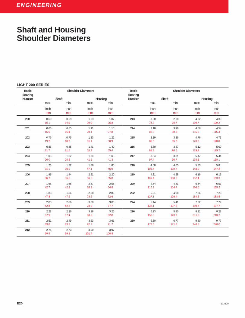
E20 102800
ENGINEERING
Shaft and HousingShoulder Diameters
LIGHT 200 SERIES
Basic Shoulder Diameters Basic Shoulder DiametersBearing BearingNumber Shaft Housing Number Shaft Housing
max. min. max. min. max. min. max. min.
inch inch inch inch inch inch inch inchmm mm mm mm mm mm mm mm
200 0.60 0.59 1.03 1.02 213 3.00 2.98 4.32 4.3015.1 14.9 26.0 25.8 76.2 75.7 109.7 109.2
201 0.66 0.65 1.11 1.10 214 3.18 3.16 4.56 4.5416.6 16.4 28.1 27.8 80.8 80.3 115.8 115.3
202 0.76 0.75 1.23 1.22 215 3.39 3.36 4.76 4.7319.2 18.9 31.1 30.9 86.0 85.2 120.8 120.0
203 0.86 0.85 1.41 1.40 216 3.60 3.57 5.12 5.0921.7 21.5 35.7 35.4 91.3 90.6 129.9 129.2
204 1.03 1.02 1.64 1.63 217 3.84 3.81 5.47 5.4426.0 25.8 41.5 41.3 97.4 96.7 138.8 138.1
205 1.23 1.22 1.86 1.85 218 4.08 4.05 5.83 5.831.1 30.9 47.1 46.9 103.5 102.7 148.0 147.2
206 1.45 1.44 2.21 2.20 219 4.31 4.28 6.19 6.1636.7 36.5 56.0 55.8 109.4 108.6 157.1 153.3
207 1.68 1.66 2.57 2.55 220 4.54 4.51 6.54 6.5142.7 42.2 65.3 64.8 115.2 114.4 166.0 165.2
208 1.88 1.86 2.88 2.86 222 5.01 4.98 7.26 7.2347.8 47.2 73.2 72.6 127.1 126.4 184.3 183.5
209 2.08 2.06 3.08 3.06 224 5.44 5.41 7.82 7.7952.8 52.3 78.2 77.7 138.1 137.3 198.5 197.7
210 2.28 2.26 3.28 3.26 226 5.93 5.90 8.31 8.2857.9 57.4 83.3 82.8 150.5 149.7 211.0 210.2
211 2.51 2.49 3.63 3.61 230 6.80 6.77 9.80 9.7763.8 63.3 92.2 91.7 172.6 171.8 248.8 248.0
212 2.75 2.73 3.99 3.9769.9 69.3 101.4 100.8

E21102800
ENGINEERING
MEDIUM 300 SERIES
Basic Shoulder Diameters Basic Shoulder DiametersBearing BearingNumber Shaft Housing Number Shaft Housing
max. min. max. min. max. min. max. min.
inch inch inch inch inch inch inch inchmm mm mm mm mm mm mm mm
301 0.70 0.69 1.27 1.26 311 2.65 2.63 4.28 4.2617.7 17.4 32.1 31.9 67.3 66.8 108.7 108.2
302 0.88 0.87 1.41 1.40 312 2.88 2.86 4.64 4.6222.2 22.0 35.7 35.4 43.2 72.6 117.9 117.3
303 0.90 0.89 1.66 1.65 313 3.16 3.14 4.99 4.9722.7 22.5 42.0 41.8 80.3 79.8 126.8 126.2
304 1.19 1.18 1.84 1.83 314 3.36 3.34 5.34 5.3230.1 29.9 46.6 46.4 85.3 84.8 135.6 135.1
305 1.27 1.26 2.20 2.19 315 — — — —32.1 31.9 55.8 55.5 — — — —
306 1.49 1.48 2.57 2.56 316 — — — —37.7 37.5 65.2 64.9 — — — —
307 1.72 1.70 2.84 2.82 317 — — — —43.7 43.2 72.1 71.6 — — — —
308 1.96 1.94 3.20 3.18 318 — — — —49.8 49.3 81.3 80.8 — — — —
309 2.20 2.18 3.55 3.53 319 4.46 4.43 7.22 7.1955.9 55.4 90.2 89.7 113.2 112.4 183.3 182.5
310 2.41 2.39 3.93 3.9161.2 60.7 99.8 99.3
EN
GIN
EE
RIN
G
Shaft and HousingShoulder Diameters

E22 102800
ENGINEERING
Bearing Locknut ApproximateBore Torque Clamping Force(mm) (ft-lb) (lb)
10 10-20 1,620-3,24012 10-20 1,340-2,68015 10-20 1,070-2,14017 10-20 940-1,88020 12-35 950-2,770
25 23-50 1,450-3,17030 32-60 1,690-3,17035 39-70 1,750-3,14040 50-80 1,970-3,14045 64-90 2,220-3,120
50 67-100 2,090-3,12055 82-125 2,330-3,54060 99-150 2,560-3,88065 131-175 3,130-4,19070 152-200 3,360-4,430
75 173-250 3,610-5,22080 197-275 3,840-5,35085 222-325 4,060-5,94090 248-375 4,280-6,48095 277-425 4,520-6,950
100 345-475 5,360-7,380105 380-550 5,620-8,120110 380-550 5,340-7,740120 380-550 4,900-7,080130 380-550 4,510-6,540
140 380-550 4,190-6,070150 380-550 3,910-5,660160 380-550 3,680-5,330
Locknut TorqueLocknut torques are standardized regardless of thetype of locknut used. Acceptable locknut torques fordry thread engagement are shown in the followingtable. Bearing locknuts shall be tightened using atorque wrench and a two-point locknut wrench or othersuitable torque wrench adapter.
Reference MIL-B-17931F

E23102800
ENGINEERING
To better match machine tool bearings to spindles,Torrington offers micron coding. Micron coding isstandard on all products except ball screw supportbearings and Ex-Cell-O bearings.
Micron coding is based on average bore and O.D.diameters. This type of coding indicates the deviationfrom the nominal size in microns.
The coding is marked on the faces of the inner andouter rings and on the box label.
Micron Bore & O.D. coding
DEVIATION FROM NOMINAL
MicronMicron Inch Coding
Over Incl.
0 -1 0.000000 -0.000039 1-1 -2 -0.000039 -0.000079 2-2 -3 -0.000079 -0.000118 3-3 -4 -0.000118 -0.000157 4-4 -5 -0.000157 -0.000197 5-5 -6 -0.000197 -0.000236 6-6 -7 -0.000236 -0.000276 7-7 -8 -0.000276 -0.000315 8-8 -9 -0.000315 -0.000354 9-9 -10 -0.000354 -0.000394 10
-10 -11 -0.000394 -0.000433 11-11 -12 -0.000433 -0.000472 12-12 -13 -0.000472 -0.000512 13
EN
GIN
EE
RIN
G

E24 102800
ENGINEERING
Recommended Ballscrew (inch series)Shaft and Housing Tolerances
Shaft and Housing Diameters (Inch Series)Bearing Bearing Bore Shaft Bearing O.D. HousingNumber Diameter Diameter Diameter Diameter
max. min. max. min. max. min. max. min.
inch inch inch inch inch inch inch inchmm mm mm mm mm mm mm mm
MM9306WI2H 0.7874 0.7872 0.7872 0.7870 1.8504 1.8501 1.8507 1.850420.000 19.995 19.995 19.990 47.000 46.994 47.006 47.000
MM9308WI2H 0.9385 0.9383 0.9383 0.9381 2.4409 2.4406 2.4412 2.440923.838 23.833 23.833 23.828 62.000 61.993 62.007 62.000
MM9310WI2H 1.5000 1.4997 1.4997 1.4994 2.8346 2.8343 2.8349 2.834638.100 38.094 38.094 38.088 72.000 71.993 72.007 72.000
MM9311WI3H 1.7510 1.7507 1.7507 1.7504 3.0000 2.9997 3.0003 3.000044.475 44.469 44.469 44.463 76.200 76.193 76.207 76.200
MM9313WI5H 2.2500 2.2497 2.2497 2.2494 3.5433 3.5430 3.5436 3.543357.150 57.143 57.143 57.136 90.000 89.992 90.008 90.000
MM9316WI3H 3.0000 2.9997 2.9997 2.9994 4.3307 4.3304 4.3310 4.330776.200 76.193 76.193 76.186 110.000 109.992 110.008 110.000
MM9321WI3 4.0000 3.9997 3.9997 3.9994 5.7087 5.7083 5.7091 5.7087101.600 101.592 101.592 101.584 145.000 144.991 145.009 145.000
MM9326WI6H 5.0000 4.9997 4.9997 4.9994 7.0866 7.0862 7.0870 7.0866127.000 126.992 126.992 126.984 180.000 179.990 180.010 180.000

E25102800
ENGINEERING
Recommended Ballscrew (metric series)Shaft and Housing Tolerances
Shaft and Housing Diameters (Metric Series)Bearing Bearing Bore Shaft Bearing O.D. HousingNumber Diameter Diameter Diameter Diameter
max. min. max. min. max. min. max. min.
inch inch inch inch inch inch inch inchmm mm mm mm mm mm mm mm
MM17BS47 0.6693 0.6691 0.6691 0.6689 1.8504 1.8501 1.8507 1.850417.000 16.996 16.996 16.992 47.000 46.994 47.006 47.000
MM20BS47 0.7874 0.7872 0.7872 0.7870 1.8504 1.8501 1.8507 1.850420.000 19.995 19.995 19.990 47.000 46.994 47.006 47.000
MM25BS52 0.9843 0.9841 0.9841 0.9839 2.0472 2.0469 2.0475 2.047225.000 24.995 24.995 24.990 52.000 51.993 52.007 52.000
MM25BS62 0.9843 0.9841 0.9841 0.9839 2.4409 2.4406 2.4412 2.440925.000 24.995 24.995 24.990 62.000 61.993 62.007 62.000
MM30BS62 1.1811 1.1809 1.1809 1.1807 2.4409 2.4406 2.4412 2.440930.000 29.995 29.995 29.990 62.000 61.993 62.007 62.000
MM30BS72 1.1811 1.1809 1.1809 1.1807 2.8346 2.8343 2.8349 2.834630.000 29.995 29.995 29.990 72.000 71.993 72.007 72.000
MM35BS72 1.3780 1.3777 1.3777 1.3774 2.8346 2.8343 2.8349 2.834635.000 34.994 34.994 34.988 72.000 71.993 72.007 72.000
MM40BS72 1.5748 1.5745 1.5745 1.5742 2.8346 2.8343 2.8349 2.834640.000 39.994 39.994 39.988 72.000 71.993 72.007 72.000
MM45BS75 1.7717 1.7714 1.7714 1.7711 2.9528 2.9525 2.9531 2.952845.000 44.994 44.994 44.988 75.000 74.993 75.007 75.000
MM40BS90 1.5748 1.5745 1.5745 1.5742 3.5433 3.5430 3.5436 3.543340.000 39.994 39.994 39.988 90.000 89.992 90.008 90.000
MM50BS90 1.9685 1.9682 1.9682 1.9679 3.5433 3.5430 3.5436 3.543350.000 49.994 49.994 49.988 90.000 89.992 90.008 90.000
MM55BS90 2.1654 2.1651 2.1651 2.1648 3.5433 3.5430 3.5436 3.543355.000 54.993 54.993 54.986 90.000 89.992 90.008 90.000
MM35BS100 1.3780 1.3777 1.3777 1.3774 3.9370 3.9367 3.9373 3.937035.000 34.994 34.994 34.988 100.000 99.992 100.008 100.000
MM40BS100 1.5748 1.5745 1.5745 1.5742 3.9370 3.9367 3.9373 3.937040.000 39.994 39.994 39.988 100.000 99.992 100.008 100.000
MM45BS100 1.7717 1.7714 1.7714 1.7711 3.9370 3.9367 3.9373 3.937045.000 44.994 44.994 44.988 100.000 99.992 100.008 100.000
MM50BS100 1.9685 1.9683 1.9683 1.9680 3.9370 3.9367 3.9373 3.937050.000 49.994 49.994 49.988 100.000 99.992 100.008 100.000
MM75BS110 2.9528 2.9525 2.9525 2.9522 4.3307 4.3304 4.3310 4.330775.000 74.993 74.993 74.986 110.000 109.992 110.008 110.000
MM55BS120 2.1654 2.1651 2.1651 2.1648 4.7244 4.7241 4.7247 4.724455.000 54.993 54.993 54.986 120.000 119.992 120.008 120.000
MM60BS120 2.3622 2.3619 2.3619 2.3616 4.7244 4.7241 4.7247 4.724460.000 59.993 59.993 59.986 120.000 119.992 120.008 120.000
MM100BS150 3.9370 3.9367 3.9367 3.9364 5.9055 5.9052 5.9059 5.9055100.000 99.992 99.992 99.984 150.000 149.991 150.009 150.000
EN
GIN
EE
RIN
G

E26 102800
ENGINEERING
To better match machine tool bearings to spindles,Torrington currently offers Bottom/Top bore and O.D.coding as standard for angular contact superprecisionbearings.
The code is a mark on the box label with the borecode shown above the O.D. code. The tolerances aresplit in half as shown in the figure below. If the bore andO.D. sizes fall in the half closest to nominal, this is
Bore and O.D. Coding
Offering bore and O.D. coding makes it easier to obtainthe optimum recommended fits for spindles. Eachbearing in a set is matched to within half the bore andO.D. tolerance to insure equal load sharing. It also
considered the top half and the set will be marked witha T/T. With a T/T code, the bore and O.D. toleranceswould meet ABEC 9 requirements. If the bore and O.Dsizes fall in the half farthest from the nominal, this isconsidered the bottom half and the set will be markedwith a B/B. If the bore is in the top half and O.D. is inthe bottom half, the set will be marked T/B and viceversa B/T.
enables our customers to use pairs of bearings withsame bore and O.D. codes to make triplex andquadruplex sets.
BORE
O.D.
T
B
T B
BT
TOTAL BORE TOLERANCE
NOMINAL O.D. DIMENSION
NOMINAL BORE DIMENSION
TOTAL O.D. TOLERANCE
BOTTOM/TOP BORE & O.D. CODING

E27102800
ENGINEERING
200 Series 9100 Series 99100 Series
Bore Lube Inlet Bore Lube Inlet Bore Lube InletNumber Diameter Number Diameter Number Diameter
(inches) (inches) (inches)
00 0.6950 00 0.6290 00 —01 0.7660 01 0.7200 01 —02 0.8850 02 0.8490 02 —03 1.1015 03 0.9420 03 0.937004 1.1893 04 1.1200 04 1.1080
05 1.3938 05 1.3120 05 1.305006 1.6608 06 1.5690 06 1.595507 1.9313 07 1.7840 07 1.810808 2.1623 08 1.9953 08 2.063509 2.3593 09 2.2248 09 2.2495
10 2.5558 10 2.4218 10 2.446511 2.8263 11 2.6918 11 2.728312 3.0963 12 2.8888 12 2.925813 3.3793 13 3.0858 13 3.121814 3.5638 14 3.3558 14 3.4033
15 3.7608 15 3.5533 15 3.641316 4.0308 16 3.8233 16 3.881017 4.3010 17 4.0285 17 4.086818 4.5705 18 4.2900 18 4.345319 4.8410 19 4.4870 19 4.5403
20 5.1115 20 4.7135 20 4.781321 5.4061 21 4.9610 22 5.300822 5.6540 22 5.2360 24 5.694824 6.1190 24 5.6325 26 6.321026 6.3850 26 6.1710
30 7.8160 28 6.575030 7.032032 7.500034 7.846040 9.5150
Lube Inlet Diameters
EN
GIN
EE
RIN
G

E28 102800
ENGINEERING
300 SERIES 9300 SERIES 9100 HX SERIES
Bore Lube Inlet Bore Lube Inlet Bore Lube InletNumber Diameter Number Diameter Number Diameter
(inches) (inches) (inches)
00 — 00 — 00 —01 0.8520 01 — 01 —02 1.0120 02 0.7840 02 —03 1.0910 03 0.8630 03 —04 1.2328 04 1.0458 04 1.114
05 1.5238 05 1.2093 05 1.30606 1.7908 06 1.4393 06 1.54907 2.0363 07 1.6828 07 1.78508 2.3043 08 1.9063 08 2.00109 2.5768 09 2.0308 09 2.212
10 2.8473 10 2.2998 10 2.40811 3.1173 11 2.5418 11 2.73012 3.3848 12 2.7383 12 2.92613 3.6573 13 2.9363 13 3.11114 3.9268 14 3.2068 14 3.393
15 3.4033 15 3.59016 3.5993 16 3.86117 3.8828 18 4.35518 4.0683 20 4.74528 6.1985 22 5.335
24 5.708
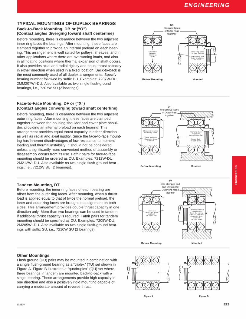
E29102800
ENGINEERING
TYPICAL MOUNTINGS OF DUPLEX BEARINGSBack-to-Back Mounting, DB or (“O”)(Contact angles diverging toward shaft centerline)Before mounting, there is clearance between the two adjacentinner ring faces the bearings. After mounting, these faces areclamped together to provide an internal preload on each bear-ing. This arrangement is well suited for pulleys, sheaves, and inother applications where there are overturning loads, and alsoin all floating positions where thermal expansion of shaft occurs.It also provides axial and radial rigidity and equal thrust capacityin either direction when used in a fixed location. Back-to-back isthe most commonly used of all duplex arrangements. Specifybearing number followed by suffix DU. Examples: 7207W-DU,2MM207WI-DU. Also available as two single flush-groundbearings, i.e., 7207W SU (2 bearings).
Face-to-Face Mounting, DF or (“X”)(Contact angles converging toward shaft centerline)Before mounting, there is clearance between the two adjacentouter ring faces. After mounting, these faces are clampedtogether between the housing shoulder and cover plate shoul-der, providing an internal preload on each bearing. Thisarrangement provides equal thrust capacity in either directionas well as radial and axial rigidity. Since the face-to-face mount-ing has inherent disadvantages of low resistance to momentloading and thermal instability, it should not be consideredunless a significantly more convenient method of assembly ordisassembly occurs from its use. Fafnir pairs for face-to-facemounting should be ordered as DU. Examples: 7212W-DU,2M212WI-DU. Also available as two single flush-ground bear-ings, i.e., 7212W SU (2 bearings).
Tandem Mounting, DTBefore mounting, the inner ring faces of each bearing areoffset from the outer ring faces. After mounting, when a thrustload is applied equal to that of twice the normal preload, theinner and outer ring faces are brought into alignment on bothsides. This arrangement provides double thrust capacity in onedirection only. More than two bearings can be used in tandemif additional thrust capacity is required. Fafnir pairs for tandemmounting should be specified as DU. Examples: 7205W-DU,2M205WI-DU. Also available as two single flush-ground bear-ings with suffix SU, i.e., 7210W SU (2 bearings).
Other MountingsFlush ground (DU) pairs may be mounted in combination witha single flush-ground bearing as a “triplex” (TU) set shown inFigure A. Figure B illustrates a “quadruplex” (QU) set wherethree bearings in tandem are mounted back-to-back with asingle bearing. These arrangements provide high capacity inone direction and also a positively rigid mounting capable ofcarrying a moderate amount of reverse thrust.
Inner ring facesclamped together
These Inner andOuter ring faces
are flush
Clearancebetween
Inner ringfaces
DB Stamped facesof Outer rings
together
MountedBefore Mounting
Figure A Figure B
Under thrust loadequivalent to
twice the normalpreload. Inner andOuter ring faces
are flushon both sides
DT One stamped and
one unstampedOuter ring face
together
MountedBefore Mounting
Inner andouter ring faces
not flushon either side
Inner and Outerring faces
clamped together
Clearance betweenOuter ring faces
DF Unstamped faces
of Outer ringstogether
MountedBefore Mounting
These Inner andOuter ring faces
not flushFaces flush
on both sides
DBStamped facesof Outer rings
together
DFUnstamped faces
of Outer ringstogether
DTOne stamped andone unstampedOuter ring faces
together
EN
GIN
EE
RIN
G

E30 102800
ENGINEERING
Back-To-Back VersusFace-To-Face MountingsMountings having bearings applied in any of the face-to-face (DF) arrangements are objectionable because theyprovide the least rigidity. Furthermore, when the operatingspeeds are comparatively high, such mountings may buildup bearing preload excessively because the temperaturegradient between the housings, bearings, and shafts.As this gradient increases, the bearing preload builds up,starting a vicious cycle which may lead to prematurespindle failure.
In spindle mountings, the shaft temperature usuallychanges at a faster rate than the housing, creating tem-perature differentials between the two members. These aredue to their difference in mass and their respective abilitiesto act as heat sinks. Thus, the shaft and the inner-ringspacer expand at a faster rate rather than the housing andthe outer-ring spacer. As the shaft expands longitudinallyand the inner-ring spacer lengthens, a thrust load builds upon each bearing and continues to increase until the equilib-rium temperature is reached. This occurs when the tem-perature at the housing levels off and the heat transferredfrom the bearings balances the heat generated in them.Therefore, if the housing attains an excessively high tem-perature, the initial bearing is built up considerably.
In a face-to-face mounting, Figure 5, the shaft expandsradially and longitudinally and the inner-ring spacer length-ens, but at a faster rate than the outer-ring spacer. Thisthermal expansion causes an additional thrust to be im-posed on both inner rings, increasing the preload of thebearings. Conversely, in back-to-back mounting, Figure 6,the longitudinal expansion of the inner-ring spacer tends torelieve, rather than build up, the bearing preload.
The two back-to back pairs, shown in Figure 7, aremounted so that the two middle bearings are face-to-face.As previously observed, temperature differentials cause thepreload of these inside bearings to increase during opera-tion. This mounting operation is not recommended. Inbearing mountings of the type seen in Figure 8, unduethrust loads are put on the two outside bearings as thetemperature along the shaft becomes higher than at thehousing. The two inside bearings unload, starting a viciouscycle of increasing temperature, preload build-up, andlubricant depletion. This is also an unacceptable mountingarrangement, and is not recommended. The same bear-ings are shown correctly mounted in tandem and arrangedback-to-back in Figure 9. Lateral expansion of the shaftand inner-ring spacer of such mountings increase neitherthrust loading nor bearing preload.
Therefore, in order to prevent increases in preload dueto the thermal expansion, back-to-back mountings arepreferred for bearings on machine tool spindles. Whentwo pairs are used, each pair should be mounted in tandombut the combination should be arranged back-to-back as inFigure 9.
FACE-TO-FACEMOUNTING
BACK-TO-BACKMOUNTING
TWO BACK-TO-BACK PAIRS
TWO FACE-TO-FACE PAIRS
TWO TANDEM PAIRSMOUNTED DB
Figure 5 – DF Mounting, Fixed
Figure 6 – DB Mounting, Fixed
Figure 7 – DB-DB Mounting, Fixed (Not Recommended)
Figure 8 – DF-DF Mounting, Fixed (Not Recommended)
Figure 9 – DT-DB Mounting, Fixed

E31102800
ENGINEERING
Spring Loaded MountingsFor high speed applications, radial and axial rigidity andsmooth spindle performance may be obtained by springloading the ball bearings with a predetermined thrust load.Spring loading allows the spindle to float laterally duringtemperature changes without appreciably increasing ordecreasing the original spring thrust load.
As the inner ring heats up during operation it expandsradially. This radial expansion applies an increasing loadthrough the ball and outer ring and finally to the preloadsprings. The preload springs deflect slightly to compensatefor the loads due to thermal expansion and maintain aconsistent load on the spindle system.
In some applications, single, spring-loaded bearingsare employed at the front and rear locations, mounted inback-to-back arrangement. Other mountings, similarlyspring loaded, have a pair of bearings installed in tandemat each end of the spindle in back-to-back arrangement(DT-DB). In either case, the spring pressure is applied tothe pulley-end or rear bearing position, placing the shaftin tension between the two bearing locations.
High Contact Angle • High Axial Rigidity• Moderate Radial Rigidity
Low Contact Angle • High Radial Rigidity• Moderate Axial Rigidity
PreloadingPreloading of precision ball bearings to a predeterminedthrust load for universal mounting is accomplished bygrinding off a certain amount of stock off faces of the innerand outer rings so that before mounting the bearing onfaces on the abutting side are offset an amount equal tothe deflection under “preload”. When mounted, these facesare clamped together, the opposite bearing faces becomeflush and the bearing parts are subjected to compressiveforces, bringing the balls into contact with their respectiveraceways, to take up the initial clearances of the bearings.Thus, the preload built into the bearings is automaticallyobtained. The condition of a preloaded ball bearing issimilar to that of one in operation under thrust load. Thisinitial thrust load serves to decrease markedly the axialand radial deflections when subsequent operational loadsare imposed on the bearing assembly.
Bearings are preloaded no more than necessary.Excessive preload adds little to the rigidity of the spindlebut appreciably reduces the range of operating speeds bycausing bearings to run hot at higher speeds. To meetconditions of speed, mounting arrangement and maximumrigidity consistent with low operating temperatures, Fafnirprecision ball bearings are designed and produced withpreloads varying from heavy to zero and, in some in-stances, with negative preload.
In many cases, the amount of bearing preload is atrade-off between having the desired degree of rigidity andreducing any adverse effect preloading has on the equip-ment. If the operating speed is high, a heavy preload canlead to excessively high operating temperatures, resulting inearly bearing failure. For these reasons, three classes ofball bearing preloads are used – Light, Medium and Heavy.
2MM209WI BEARING
THRUST
100 200 300 400 500 600 700 800 900
.005
.004
.003
.002
.001
A
B
C
D
In certain applications, such as high-speed motorized routerspindles, specially preloaded, superprecision ball bearingsare required. Such bearings are “zero” preloaded – that is,the faces of the inner and outer rings are ground flushunder negligible load.
The Light, Medium and Heavy standard preload valuesfor Fafnir superprecision angular-contact ball bearings andfor both high and low contact angles in “Physical Character-istics”.
Axial deflection curves of various preload conditions forduplex pairs of 2MM209WI superprecision ball bearings areshown in figure 10 and the radial deflection curves for thesame bearings are shown in Figure 11.
Effect of Preload on Axial Deflection
Thrust Load in Lbs.A No PreloadB Light Preload 40 lbs.C Medium Preload 125 lbs.D Heavy Preload 250 lbs.
Figure 10 – Axial Deflection Curves
Axi
al D
efle
ctio
n in
Inch
es
RADIAL
100 200 300 400 500 600 700 800 900
2MM209WI BEARING
.0006
.0005
.0004
.0003
.0002
.0001
ABC
D
Effect of Preload on Radial Deflection
Rad
ial D
efle
ctio
n in
Inch
es
Radial Load in Lbs.A No PreloadB Light Preload 40 lbs.C Medium Preload 125 lbs.D Heavy Preload 250 lbs.
Figure 11 – Radial Deflection Curves
EN
GIN
EE
RIN
G

E32 102800
ENGINEERING
Bearing SelectionFafnir angular-contact precision ball bearings are availablewith high (25°) and low (15° – 18°) contact angles. Each typehas inherent characteristics that are desirable for machine toolspindles. Low contact angle bearings are more rigid radiallyand less rigid axially than high contact angle bearings. Abearing having a low contact angle allows more axial yield andless radial deflection than one having a high contact angle.
In selecting the proper size and type of bearing, consider-ation is given to the size and construction of the spindle andthe kind of mounting, since the latter relates directly to thespindle rigidity and the deflection characteristics. In general,where the operating load is principally radial, low contact angletype bearings are selected, but where the loading is chiefly inthrust and a high degree of axial rigidity is required, highercontact angle type bearings are recommended. Therefore, forthe majority of applications, superprecision ball bearings withlow contact angles are used. However, when maximum axialrigidity is required in combination with heavy thrust loads orwhen high ambient temperatures are involved, bearings havingthe higher contact angles are preferred. The three establishedpreload values are necessarily higher for high contact anglebearings than for those having low contact angles. The axialand radial deflection characteristics of low angular-contact, lightseries, preloaded ball bearings of a standard size are shown infigure 12. Curves C and D, which are for a preloded tandempair of such bearings, indicate the greatly reduced axial andradial deflections as compared to those for a preloded single
100 200 300 400 500 600 700 800
.0030
.0025
.0020
.0015
.0010
.0005
A
C
100 200 300 400 500 600 700 800
.0008
.0007
.0006
.0005
.0004
.0003
.0002
.0001
B
D
Axi
al D
efle
ctio
n
Rad
ial D
efle
ctio
n
Radial Load – lbs.B Preloaded DBD Preloaded Tandem
Figure 12 – Axial vs Radial Deflections
EFFECT OF SINGLE AND TANDEM MOUNTING ON AXIAL AND RADIAL RIGIDITY
EFFECTS OF CONTACT ANGLE ON AXIAL DEFLECTION
100 200 300 400 500 600 700
.004
.003
.002
.001
A
B
C
D
100 200 300 400 500 600 700
.004
.003
.002
.001
A
BCD
Low Contact Angle
Less Axial Rigidity
Axi
al D
efle
ctio
n
High Contact Angle
Figure 13 – Axial Deflections
2MM 15° Contact Angle 3MM 25° Contact AnglePreload Force in Pounds Preload Force in Pounds
Light 30 60Medium 60 120Heavy 120 240
bearing of the same size (Curves A and B). For example, atandem pair of bearings under a thrust load of 600 poundswould have an axial defection of 0.0010 inch, while that for asingle bearing would be about 0.0017 inch. Similarly, theradial deflections for these bearings operated under 600pounds radial loads would be 0.00024 inch and 0.00049 inch.
Axial deflection curves for the standard preload levels forboth the 2MM (15° contact angle) and the 3MM (25° contactangle) are shown in Figure 13. Please note the force for theequivalent preload level for a 2MM bearing is about one-halfthat of the preload level for a 3MM bearing. Preload values forall Fafnir machine toll grade angular-contact bearings havebeen calculated to give optimum performance by machinedesigners.
A comparison of the curves in Figure 13 shows the 25°contact angle bearing to be more rigid under axial loads thanthe 15° contact angle bearing. Note that the axial deflectionfor the 2MM 15° contact angle preloaded pair of bearings witha medium preload (60 pounds) is 0.0013" under a 300 poundthrust load. The 3MM 25° contact angle preloaded pair with alight preload (60 pounds) deflects 0.0008" under the same300 pound thrust load.
Thrust Load – lbs.A No Preload C Medium Preload 125lbs.B Light Preload 40lbs. D Heavy Preload 250lbs.
Thrust Load – lbs.A No Preload C Medium Preload 125lbs.B Light Preload 40lbs. D Heavy Preload 250lbs.
Axi
al D
efle
ctio
n
Thrust Load – lbs.A Preloaded DBC Preloaded Tandem
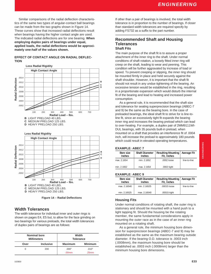
E33102800
ENGINEERING
Similar comparisons of the radial deflection characteris-tics of the same two types of angular-contact ball bearingscan be made from the two graphs shown in Figure 14.These curves show that increased radial deflections resultwhen bearings having the higher contact angle are used.The indicated radial deflections are for one bearing. Whenemploying duplex pairs of bearings under equal,applied loads, the radial deflections would be approxi-mately one-half of the values shown.
EFFECT OF CONTACT ANGLE ON RADIAL DEFLEC-TION
Rad
ial D
efle
ctio
n
100 200 300 400 500 600 700
.0014
.0012
.0010
.0008
.0006
.0004
.0002
BC
D
Rad
ial D
efle
ctio
n
Less Radial Rigidity
High Contact Angle
Radial Load – lbs.B LIGHT PRELOAD 40 LBS.C MEDIUM PRELOAD 125 LBS.D HEAVY PRELOAD 250 LBS.
Figure 14 – Radial Deflections
Less Radial Rigidity
High Contact Angle
100 200 300 400 500 600 700
.0014
.0012
.0010
.0008
.0006
.0004
.0002
B
CD
Radial Load – lbs.B LIGHT PRELOAD 40 LBS.C MEDIUM PRELOAD 125 LBS.D HEAVY PRELOAD 250 LBS.
Width TolerancesThe width tolerance for individual inner and outer rings isshown on pages E4, E5 but, to allow for the face grinding ontwo bearings for various preloads, the total width tolerancesof duplex pairs of bearings are as follows:
Nominal bore WidthMillimeters Tolerance
Over Inclusive Maximum Minimum
0 200 .000" .010"
.00mm .25mm
If other than a pair of bearings is involved, the total widthtolerance is in proportion to the number of bearings. If closerthan standard width tolerances are required specify byadding FS732 as a suffix to the part number.
Recommended Shaft and HousingTolerancesShaft FitsThe main purpose of the shaft fit is to assure a properattachment of the inner ring to the shaft. Under normalconditions of shaft rotation, a loosely fitted inner ring willcreep on the shaft, leading to wear and peening. Thiscondition will be further aggravated by increase of load orspeed. To prevent creeping or slipping, the inner ring shouldbe mounted firmly in place and held securely against theshaft shoulder. However, it is important that the shaft fitshould not result in any undue tightening of the bearing. Anexcessive tension would be established in the ring, resultingin a proportionate expansion which would disturb the internalfit of the bearing and lead to heating and increased powerconsumption.
As a general rule, it is recommended that the shaft sizeand tolerance for seating superprecision bearings (ABEC-7and 9) be the same as the bearing bore. In the case ofpreloaded bearings, the ideal shaft fit to strive for is line-to-line fit, since an excessively tight fit expands the bearinginner ring and increases the bearing preload which can leadto over-heating. For example, a duplex pair of 2MM9111WI-DUL bearings, with 35 pounds built-in preload, whenmounted on a shaft that provides an interference fit of .0004inch, will increase the preload to approximately 180 poundswhich could result in elevated operating temperatures.
EXAMPLE: ABEC 7Bore size Shaft Diameter Resulting Mounting Average Fit
Inches Inches Fit, Inchesmax. 2.1654 min. 2.1652 .0002 loose line-to-line
min. 2.1652 max. 2.1654 .0002 tight
EXAMPLE: ABEC 9Bore size Shaft Diameter Resulting Mounting Average Fit
Inches Inches Fit, Inchesmax. 2.16540 min. 2.16525 .00015 loose line-to-line
min. 2.16525 max. 2.16540 .00015 tight
Housing FitsUnder normal conditions of rotating shaft, the outer ring isstationary and should be mounted with a hand push to alight tapping fit. Should the housing be the rotatingmember, the same fundamental considerations apply inmounting the outer race as in the case of an inner ringmounted on a rotating shaft.
As a general rule, the minimum housing bore dimen-sion for superprecision bearings (ABEC-7 and 9) may beestablished as the same as the maximum bearing outsidediameter. If the bearing O.D. tolerance is .0003 inch(.0008mm), the maximum housing bore should beestablished as .0003 inch (.0008mm) larger than theminimum housing bore dimensions.
EN
GIN
EE
RIN
G

E34 102800
ENGINEERING
EXAMPLE: ABEC 7Outside Diameter Housing Bore Resulting Mounting Fit Average Fit
Inches Inches Inches Inchesmax. 3.5433 min. 3.5433 .0000 tight .0003 loosemin. 3.5430 max. 3.5436 .0006 loose
EXAMPLE: ABEC 9Outside Diameter Housing Bore Resulting Mounting Fit Average Fit
Inches Inches Inches Inchesmax. 3.54330 min. 3.54330 .0000 tight .0002 loosemin. 3.54310 max. 3.54350 .0004 loose
Tables covering recommended shaft and housing seatdimensions for superprecision (ABEC-7) ball bearings areshown on pages E8 through E15.
The “average” mounting fit is usually considered the idealmounting condition and should be obtained.
To accomplish this, it is important to follow the tabulatedtolerances, except when deviations are recommended by theEngineering Department. It is equally important that all shaftand housing shoulders be square and properly relieved toassure accurate seating and positioning of the bearings in themounting.
On high-speed applications where nearby heat input isalong the shaft, it is extremely important that the floatingbearings can move axially to compensate for thermalchanges. Ball bearings cannot float longitudinally if they arerestricted by tight housing bores or by the radial expansion ofthe bearing itself due to temperature differentials. Therefore,in such cases, the housing mounting fit for the floatingbearings is slightly looser than the tabulated average fit.Likewise, in spring-loaded ball bearing applications thehousing mounting fit must be free enough to permit axialmovement of the bearings under the spring pressure, duringall conditions of operation. The recommended housingdimensions to ensure proper “float” of the bearings underaverage conditions are tabulated on pages E13 and E15.
ShaftsShafts are preferably made from steel hardened and groundall over; and where not otherwise unsuitable, a hardness of45-50 Rockwell C has been successful. When designing aspindle or shaft it is highly desirable to plan so that it can beground all over in one setting as a final operation. Thispromotes true balance and running accuracy, which is criticalin high-speed work.
Bearing SpacersSpacers are used to increase shaft rigidity, moment stiffnessand decrease deflection. Spacers, mounted between units ofa pair of bearings, are preferably made of alloy steel, hard-ened and ground and should be sturdy in cross-section andequal in length. Equal lengths can be produced by grindingthe inner-ring spacer and outer-ring spacer together. It isimportant that the faces of the spacers be square and thattheir parallelism be the best possible. All corners should berounded to remove sharp edges and burrs.
The inside diameter of the inner-ring spacers should clearthe shaft but not be so loose as to make it possible to mountand run them eccentrically. For short spacers and highoperating speeds add clearance of not more than .0010 inch(.025mm) over the maximum shaft diameter has been found
generally acceptable. For long spacers and low speeds, thisclearance may be increased to prevent the shaft fromdisturbing the face parallelism of the spacer. The spaceroutside diameter should not be less than the outside diameterof the inner ring of the bearing.
The outside diameter of the outer-ring spacers should beabout .0010 inch (.025mm) smaller than the minimum bore ofthe housing. These should have lubricant holes and grooveswhere necessary and are usually centrally located. Spacerend parallelism should be the same as the parallelismtolerance for the adjacent bearing.
Selective AssemblyUnder certain conditions it may be desirable to control fitsmore accurately without the added expense of using closertolerance bearings and assembly parts. This can be accom-plished by selective assembly of the bearings, shafts andhousings after they have been sized and sorted according tobores and outside diameters. At the customer’s request, wecan provide bearings with bore’s and O.D.’s coded in inch ormetric dimensions from nominal size. A nominal charge isrequired for this additional inspection. This improved fit-up atassembly provides a higher degree of precision in the spindle.Generally, however, it is quite satisfactory for production andfield servicing to use closer shaft and housing tolerances withbearings having a higher degree of precision.
Housing DesignHousings are usually made of cast iron or steel and generallyheat treated to lessen possible distortion. For the smaller high-speed applications, steel housings are preferable.
The bore of the housing should be ground or bored andchecked at a number of points throughout its length anddiameter to assure that it is round and does not taper.
It is preferable to mount the bearings in one casting; thispermits machining the two housing bores in one setting andassures accurate alignment of the bearings.
In many cases of housing design, it is advantageous toemploy a sub-housing or a steel sleeve between the outer ringof the bearing and the machine frame, thus allowing assemblyof the bearings on the shaft and insertion of the entire unit in tothe machine frame. This method also provides a surface ofproper hardness where machine frames are made of amaterial that has a low Brinell value, such as aluminum andother soft metals.
Shaft shoulders and housing shoulders should besquare and true, and should be of such diameters as tomeet the recommendations given on page E17 through E21.The choice between fillets and undercut reliefs rests with theindividual shaft design and conditions surrounding itsnormal use.
Where screws are used to fasten end caps into the mainhousing, adequate section should be left between the screwhole and the hosing bore. This is required to prevent distortionof the housing bore when the screws are tightened and thecovers or others parts pulled tightly into place.
Prior to assembly, shafts and housings, as well as alllubricant holes and channels, should be cleaned thoroughly, inorder to remove all chips and particles which may be carriedby the lubricant into the bearings to cause bearing damage.

E35102800
ENGINEERING
Housing SealsA labyrinth combination of slinger and end cover provides ahighly effective seal against the intrusion of foreign matter.This seal is recommended for use over a wide range ofspeeds. For exceptionally slow-speed applications, a combi-nation of slinger and commercial contact-type seal is usuallyemployed.
Slingers should be machined all over to assure true-running. Their diameters should be concentric with the bore.The outside diameter of the slinger is often tapered to throwoff cutting compounds, coolants, etc., from the point at whichsuch liquids may enter the spindle. A drip or run-off grooveadjacent to the open lip of the end cover is highly desirableand practical.
The axial clearances of the internal faces between slingerand end cover should be about 1/16 inch (1.6mm). The firstradial clearance opening on any design through which liquidmay pass should be made very close, about .007 inch(.18mm) on the diameter .0035 inch (.089mm) on a side. Theinner radial clearances should be between 0.15 inch (.38mm)and .0075 inch (.190mm). These are figures actually used insuccessful practice.
Bearing LocknutsTo position precision ball bearings on spindle shafts, precisionmanufactured self locking bearing locknuts are recommendedrather than the conventional locknuts and lockwashers usedfor bearings made to ABEC-1 tolerances.
This precision bearing nut incorporates a locking feature inits design. The nut threads deform slightly as the lockingsetscrews are tightened. This slight deformation creates aninterference with the shaft threads which prevents furtherrotation of the locknut. The precision threads of this locknutare cut square with the face to provide the necessary true-running clamping surface against the inner-ring face of theball bearings.
Successful ApplicationsDetailed assembly drawings on pages E45 to E48, arerepresentative of successful applications of Fafnir precisionbearings on such equipment as gear drive assemblies;automatic screw machines; high-cycle wheel heads; high-speed internal grinding spindles; superprecision work heads;and high-speed router spindles. It is hoped that these ar-rangements will stimulate questions regarding your particularapplication problems. They will gladly be examined by ourEngineering Department.
Special RequirementsHigh-speed grease-lubricated spindles and heavy precisionwork heads requiring unusual rigidity and running accuracyare a few of the many special problems involving precisionbearings. These and many other applications generallyrequire design features which will be recommended by theEngineering Department on request.
LubricationEven though ball bearings have the least amount of friction ofany of the so-called anti-friction bearings, lubrication is re-
quired to minimize rolling resistance due to deformation orkneading action of the balls in the raceways under load, andto minimize any sliding friction that occurs between the balls,the raceway and the retainer. Lubrication also serves toprotect the accurately ground and polished surfaces fromcorrosion. In addition, lubrication, in general, dissipatesgenerated heat and helps protect the bearing moving partsfrom the entry of foreign matter.
Only enough lubrication to accomplish these purposesshould be used since another source of heat may becomepresent, namely friction between the lubricant and the movingparts, in the form of churning or internal shear of the lubricantitself.
Regardless of the method of lubrication or type of lubri-cant, it is important that quality lubricants be used to minimizeoxidation, gumming or sludging and that the lubricant beclean and free of moisture to minimize wear.
In the lubrication of ball bearings, it is important to realizethat a small quantity of oil or grease will, if constantly presentin the bearing, suffice for its requirements. More trouble canresult from excessive lubrication than from too little, althougheither condition should be avoided. Excessive oil or greasewill result in high temperature and possibly failure. Whengrease is used, it is especially necessary to take into consid-eration the maximum operating temperature. Also particularattention must be given the housing design relating to theproximity of the grease to the bearing, in order to assureadequate purge room and grease retention.
Depending upon operating speeds, loads and tempera-tures, machine-tool ball bearings are lubricated with grease,oil or oil mist. In general, oils are required when bearingsoperate at high speeds and to provide greater cooling than ispossible with grease.
Heat GenerationWhen ball bearing spindles are grease lubricated, the heatgenerated is removed only by conduction through the sur-rounding parts. With jet or circulating oil lubrication, generatedheat is dissipated by the oil passing through the bearings aswell as by conduction through the shaft and housing. Bothmeans of removing heat from the bearings are important but,generally, dissipation through conduction is less obvious.
As an example, in an oil mist lubricated grinding spindlethe nose or wheel-end bearings are fixed and close to thegrinding coolant. The pulley-end or rear bearings are securedaxially on the shaft but permitted to float laterally in thehousing to compensate for size variations due to thermalchanges. Heat is conducted away from the front bearings at afaster rate because of the mass of the spindle nose and theintimate contact of the outer rings with the housing shoulder,the end cover, and the housing bore. This condition, coupledwith oil mist lubrication and the proximity of the grindingcoolant, takes away generated heat efficiently.
The rear or floating pair of bearings are not so favored.Usually, the mass of the shaft at the pulley-end is not sogreat. The pulley possesses some heat-conduction ability butalso receives heat generated by belt friction. The absence ofgrinding coolant and the reduced area of conduction usuallyresults in a slightly higher operating temperature.
EN
GIN
EE
RIN
G

E36 102800
ENGINEERING
Low operating temperatures, combined with adequate spindlerigidity, are important and highly desirable for precisionmachine tools. This is particularly true for high-speed grindingspindles where the preload of the bearings is the principleload imposed upon them. Some of the benefits derived fromlow operating temperatures and better dimensional stability ofthe processed work, less need for bearing lubrication, preven-tion of objectionable heat at the external surfaces of thespindle housing, and elimination of troubles due to thermaleffects on mounting fits and preloads.
The heat developed at the ball bearings under load is afunction of the operating speed and the bearing preload.Preloading is necessary for maximum axial and radial rigidity.Unfortunately, if speeds are increased, the bearing preloadmay have to be lessened to maintain proper operating tem-peratures at the bearing.
For high-speed operation, the bearing preload should besufficient to maintain proper rolling friction for the balls but notso high as to generate excessive heat. In cases where loweroperating speeds are desired, bearing preloads may beincreased to obtain additional bearing rigidity, provided theproper operating temperatures are maintained. Thus, abalance between heat generation and spindle rigidity dictatesthe amount of bearing preload that is used, commensuratewith the operational speed and the bearing life required.
How bearing preload affects the operating temperature isillustrated in Figure 15. This graph applies to 207 size, angu-lar-contact, duplexed superprecision ball bearings, mountedback-to-back. Curve A is a plot of operating temperature atthe bearing outside diameter for the speeds indicated, usingbearings with a 150 pound built-in preload. Curve B is forbearings having a 30 pound preload. The slope of Curve A ismuch steeper than that of Curve B. Using bearings with a 150pound preload, the temperature rise at the bearing outsidediameter is 60° F when operating at 3600 rpm. For the sametemperature rise, using bearings with 30 pounds preload, anoperating speed of 15,300 rpm is indicated. Therefore it isevident that for higher-speed operation the bearing preloadshould be kept to the minimum necessary to assure sufficientbearing rigidity.
For workhead spindles, the operating speeds are generallylow and the loading conditions heavy. Maximum radial andaxial spindle rigidity is required under these loads, makingincreased bearing preload mandatory.
Permissible Operating SpeedWhen determining the permissible operating speeds corre-sponding to the bearing preloads used in machine toolspindles, many influencing factors are involved. Among thoseconsidered are spindle mass and construction; type of mount-ing; spindle rigidity and accuracy requirements; spindle loads’service life; type of service, (intermittent or continuous); andmethod of lubrication.
Bearing temperatures , generally, vary directly with bothspeed and load. However, high speed applications musthave sufficient thrust loading on the bearings to prevent heatgeneration from ball skidding. The amount of bearing preloadis determined primarily from these operating conditions. Atlower speeds, the operating loads are heavier and the bearingdeflections are greater. Therefore, the bearing preload mustbe high enough to provide adequate bearing rigidity under theheaviest loads and still maintain reasonable temperatureswhen the spindle is operated at high speeds.
The following relationship may be used to estimate theeffect of preload and lubrication method on the PermissibleOperating Speed. (SP)
SP = FL x FP x FB x NGWhere
FL is Lubrication Factor
FP is Preload Factor
FB is Ball Material Factor
NG is Permissible Speed for single grease lubricated bearingwith inner ring rotation. This value is found in the PhysicalCharacteristics sections.
Factors are as follows:
LUBRICATION FACTOR (F L)
Grease FL = 1.00Oil Bath FL = 1.50Oil Mist FL = 1.70Oil Jet FL = 2.00
EFFECT OF PRELOAD ON TEMPERATURE RISE
1 2 3 4 5 6 7 8 9 10 11 12 13 14 15 16
100
90
80
70
60
50
40
30
20
B
A
Tem
pera
ture
Ris
e A
bove
Roo
m
°F
Speed in RPM 1 = 1000A High PreloadB Low Preload
Figure 15 — Temperature vs Speed
If a cage other than one shown in this catalog is used,contact the Engineering Department for recommendations.
* Ceramic balls allow 20% increase to speed factor.
BEARING PRELOAD FACTORS = (F P)
Bearing Mounting ArrangementBearing Preload
L M H
0.85 0.70 0.50
0.80 0.60 0.40
0.65 0.50 0.30
0.65 0.50 0.30
0.70 0.60 0.35
0.60 0.40 0.20
0.65 0.45 0.25
BALL MATERIAL FACTOR = (F B)
Steel Balls FB = 1.00*Ceramic Balls FB = 1.20
L
l

E37102800
ENGINEERING
0 1 2 3 4 5 6 7 8 9
200
180
160
140
120
100
80
60
40
20
HOURS
0 1 2 3 4 5 6 7 8 9
60
40
20
HOURS
6
5
4
3
2
1EXTRA-LIGHT SERIES
LIGHT SERIES
Bearing Temperature Increase Due to Break-In ProcedureLUBRICATIONGreaseThe use of grease as a lubricant for our precision bearings onvarious spindle applications is becoming more popular due tothe development of better ball bearing greases, simplificationof design and elimination of the “human maintenance factor”which is frequently responsible for too much lubrication, notenough lubrication, or the wrong kind of lubrication.Prelubricating the bearings at assembly with the correctamount of the right grease and thus eliminating all greasefittings has increased precision production in many instances.
For successful lubrication, grease for ball bearings shouldhave good mechanical and chemical stability with low torquecharacteristics. Two different types of grease, one soft andthe other heavier, have proved to be suitable lubricants formachine tool spindle bearings. The “soft” greases have aworked penetration factor of about 300. The heavier greasehas a worked penetration factor of about 200 and is of thechanneling type. All greases show a very slight change inconsistency after operation in a bearing. As the softer greasehas a tendency to churn, particular attention should be givento the quantity packed into the bearing. Because the heaviergrease is of the channeling type, the amount used is notcritical.
Below a 400,000 DN value, which is equivalent to a40mm bore bearing rotating at 10,000 rpm, either a lightconsistency grease or the channeling grease may be used.When using grease of a channeling type at low speeds , thebearing may be packed full and will operate at no appreciablerise in temperature. Bearings may also be packed full of thelighter grease, but a greater rise in temperature will be notice-able until the excess lubricant is expelled from the bearings.
At continuous speeds above a DN value of 400,000, theoperating temperature is generally lower when the bearingsare lubricated with a lower consistency grease. However, thegrease quantity in each bearing must be limited. At these highspeeds, an excessive amount of grease in the bearing mayresult in greatly increased operating temperatures, due tochurning action. This condition, if uncontrolled, may lead topremature bearing failure.
The top graph in Figure 16 shows bearing temperatureincrease due to break-in procedure. The peaking temperaturefollowed by the leveling off is a result of the new grease beingworked and then stabilized for a particular condition of loadand speed.
It is important that the peak temperature not exceed 100°Fabove room temperature since the chemical consistency andcharacteristics of the grease can be permanently altered.Thus, the proper break-in procedure is to run the machineuntil the spindle temperature rises to 150° F and then turn itoff to allow the grease to cool. Repeat until the spindle tem-perature stabilizes at a temperature below 130°F.
The bottom graph in Figure 16 shows the typical tempera-ture rise of the bearing once the grease has been worked infor the specific speed and load.
Typical Temperature After Break-In Procedure
Figure 16 – Temperature vs Time
Gra
ms
of G
reas
e in
Eac
h B
earin
g
Bearing Bore Size in MM
Figure 17 – Grease Quantity Chart
Ris
e A
bove
Roo
m T
empe
ratu
re
°F
EN
GIN
EE
RIN
G
10 15 20 25 30 35 40 45 50 55

E38 102800
ENGINEERING
It is generally recognized that only the grease which isimmediately adjacent to and in contact with the bearingcontributes to its lubrication. In most applications, unless thespeed is exceptionally low, a large quantity of grease can beobjectionable. An excessive amount increases churningaction, which may lead to overheating and possible break-down of the grease.The tendency to churn depends upon theconsistency of the grease, the bearing design, the housingconstruction and the quantity of grease that is used.
Ordinarily, bearings need to be packed only about 25% to30% full of grease. As a guide, the chart shown in Figure 17may be used to determine the approximate amount of greasewhich should be used in each bearing. The chart covers theextra-light series bearings for bore sizes of 10 to 55 mm’sinclusive.
Prior to mounting, each bearing is carefully packed withthe required quantity of clean, suitable grease using a flatsteel scale for inserting the grease into the bearing andaround the balls. Grease voids within the bearing are elimi-nated and even distribution of the grease is accomplished byrevolving the bearing slowly in the hands until the torquethroughout the bearing becomes noticeably constant.
OilAlthough several grease products have been successful atDN values as high as one million, oils are generally requiredfor bearings operating at high speeds or to provide morecooling and dissipation of heat than is possible with grease.High-grade spindle oil having a viscosity of 100 secondsSaybolt at 100°F is recommended for use in drip-feed oilers,oil bath lubrication arrangements and oil mist systems. Inheavily-loaded applications, oil in relatively large quantitiesmust be supplied, and where temperatures run higher thannormal, oil coolers will be required. Churning of a large pool ofoil is to be avoided if speed is appreciable.
Oil BathThe conventional oil-bath system for lubricating the bearingsis satisfactory for low and moderate speeds. The static oillevel must never be higher than the center of the lowermostball. When the shaft is rotating, the running level may dropconsiderably below the standstill level, depending on thespeed of the revolving parts. A sight gauge or other suitablemeans should be provided to permit an easy check.
Drip-Feed OilWhere the speeds are considered high for oil bath and thebearings are moderately loaded, oil, introduced through afilter-type, sight-feed oiler, is recommended. This assures aconstant supply of lubricant. The feed in drops per minute isdetermined by closely observing the operating temperatures.
Oil JetIn applications where the ball bearing is heavily loaded andoperating at high speed and high temperatures or where theoperating conditions are severe with high ambient tempera-tures encountered, oil jet lubrication may be required. In suchcases it is necessary to lubricate each bearing locationindividually, and to provide adequately large drain openings toprevent excessive accumulation of oil after it has passedthrough the bearings.
Oil MistOil mist lubrication is recommended for spindles runningcontinuously at high speeds. With this method of lubrication,oil of the proper viscosity is atomized into finely dividedparticles, mixed with clean, filtered, dry compressed air anddirected to pass through the bearings in a constant stream.This oil is metered into the air under pressure. Thus, thesystem not only lubricates the bearings but it affords somecooling due to the air flow. This continuous passage of air andoil through the bearings and the labyrinth seals also serves toprevent the entrance of contaminants into the bearings.
To insure the “wetting” of the bearings and to preventpossible damage to the balls and raceways, it is imperativethat the oil mist system be turned on for several minutesbefore the spindle is started. The importance of wetting thebearings before starting cannot be over stressed and hasparticular significance for spindles that have been idle forextended periods of time. To avoid such effects, most oil mistsystems have interlocks which make it impossible to start thespindle until the lubricating system is working properly and thebearings are thoroughly wetted.
Metered OilThis method is similar to the oil mist; however, the oil is fed byperiodic pulses to the lubrication line providing a higher air tooil ratio. Therefore, this method lowers the operating bearingtemperature and lubricant shear effects, enabling higheroperating speeds.
LUBE SYSTEM COMPARISONSystem Typical *
Cost Speed (DN)
Grease Low 500,000Oil Bath Low 400,000Oil Drip Low 600,000Oil Mist Medium 1,000,000Metered Oil High >1,000,000Oil Jet High >1,000,000
* Speed value is an approximation and assumes proper mountingand preload techniques along with average loading conditions. Formore specific guidance contact your local sales engineer.
The Speed, “DN”, value is obtained by multiplying the bearing boresize in millimeters by the shaft RPM.

E39102800
ENGINEERING
Grease and Speed CapabilityBefore selecting a grease, it is important to define arelative speed capability of the application. There is noprecise method that can be applied to determine theoperating speed of a bearing. Over the years, designers ofmachine tool systems have been guided by their ownexperiences from which many basic “rules of thumb” havebeen established. One such rule is the “DN” speed value.
DN = Bore in millimeters * RPMThe four most common spindle greases that Torringtonrecommends are:
Exxon Andok C – Vertical applications< 500,000 DN
Mobil 28 – Light loads < 600,000 DNChevron SRI – Medium to heavy loads
< 350,000 DNKluber Isoflex NBU 15 – Light loads, vertical or
Kluber Isoflex NCA 15 horizontal applications> 500,000 DN
These are the greases that Torrington would recommend,
equivalents to the above greases could be substituted.
Quantity of Grease:
25% to 40% pack for Normal Speed (< 500,000 DN)
15% to 20% pack for High Speed (> 500,000 DN)
LUBE SPECSLUBE CODE LUBE FS SPEC
160 AEROSHELL 22 FS381B-P044 ANDOK 260 FS167E049 ANDOK B FS104A023 ANDOK C FS118436 ANTICORIT L-245XBF FS890078 CHEVRON SRI FS545037 DOW CORNING 44 FS137A004 DRY —125 FERROCOTE 5856 BF FS639162 ISOFLEX NBU 15 FS637443 ISOFLEX NCA 15 FS905422 ISOFLEX SUPERLDS18 FS735115 ISOFLEX TOPAS NB52 FS737149 ISOFLEX TOPAS NCA15 FS883076 KRYTOX 240AB FS452161 KRYTOX 240AC FS433 — LUBCON L252 FS915086 MOBIL 28 FS381A456 MOBILITH SHC15 FS919095 MOBILTEMP SHC 32 FS612169 PQ CORROSION PREV. FS216067 RHEOTEMP 500 FS208012 WINSOR LUBE L-245X FS171A167 WINSOR LUBE L1018 FS179A
EN
GIN
EE
RIN
G

E40 102800
ENGINEERING
RUN-IN PROCEDURE FOR GREASED BEARINGS
A proper run-in procedure will provide the following results:
• Expel the excess grease found in the system
• Orient the lubricating film on each contact surface
• Establish a low equilibrium operating temperature
• Achieve a sealed-for-life lubrication condition
Run-In Procedure
1. Start at a reasonable low speed, typically 10% of themaximum operating speed.
2. Increase speed incrementally when a stable temperatureis reached.
3. Continue incremental increase in speed as described.If a rapid temperature increase occurs, stop the run-inprocess. This temperature spike indicates a preload dueto thermal expansion.
Maximum bearing temperatures should not exceed 70°C(158°F). Temperatures in excess of 70°C will cause excessivebearing preloads and possible permanent grease bearingdamage.
4. Allow the system to cool to room temperature.
5. Restart procedure at the last speed prior to the temperaturespike.
6. Continue repeating the above cycle until an equilibriumtemperature is reached at the maximum operating speed ofthe application. The ideal equilibrium operating tempera-ture is 35°C to 40°C (95°F to 105°F).
Alternative Run-In ProcedureRun-in at constant speed is also possible. In this operation, thebearing should run at full speed for about 30 seconds. Afterstopping, the heat in the bearing dissipates. In this way, adangerous temperature rise is prevented. The non-runningtime depends on the various design factors, but it should be atleast 5 times greater than the running time. This process isrepeated until the bearing temperature becomes constant.
E41102800
ENGINEERING
Life CalculationsLoad Ratings – Radial Ball BearingsThe load ratings published in this catalog are based on ABMAStandard Section 9, but are increased to reflect improve-ments in materials and processing. These ratings are referredto as EXTENDED BASIC DYNAMIC LOAD RATINGS, CE.Care must be taken that the EXTENDED BASIC DYNAMICLOAD RATINGS only be used in equations containing CE,and should not be used in any equations in prior publishedcatalogs.
Fatigue LifeBecause of the dispersion in life of identical bearings operat-ing under identical conditions, a statistical result will beobtained for bearing fatigue life. For most calculations life isexpressed as the number of hours that 90% of a group ofidentical bearings will exceed under a given set of conditions,and is referred to as the L10 life. For life values of greaterreliability than 90% refer to Table 4.
The basic equation for radial ball bearings is:
Ln = 16667 x a1 x a2 x a3 [ fB x CE ]3 Hours
N P
Calculate EQUIVALENT RADIAL LOAD (P) by using Table 1and required Y factors from Table 2.
Notations Used in this Section:C = Basic Dynamic Load Rating – Radial Roller bearings
Pounds or NewtonsCE = Extended Basic Dynamic Load Rating – Radial Ball
bearings Pounds or NewtonsCo = Basic Static load Rating – Radial Bearings
Pounds or NewtonsCoa = Basic Static Thrust Load Rating Pounds or NewtonsCt = Basic Thrust Dynamic Load Rating – Ball and Roller
BearingsK = Thrust Rating Calculation FactorKT = Relative Thrust Load Factor – Ball BearingsLf = Life factorLn = Fatigue Life for Reliability Level “r” – HoursN = Operating Speed – R.P.M.Nf = Speed FactorR = Applied Radial Load on Bearing Pounds or NewtonsP = Equivalent Radial Load on Bearing Pounds or
NewtonsTe = Equivalent Thrust Load – Thrust Ball and Roller
Bearings Pounds or NewtonsT = Applied Thrust Load on Bearings Pounds or
NewtonsX = Radial Load FactorsY, Y1, = Thrust load FactorsY2, Y3
a1 = Life adjustment Factor for reliabilitya2 = Life adjustment Factor for Bearing Materiala3 = Life adjustment Factor for Application ConditionsfB = Dynamic Load rating Adjustment factor for Number
of Adjacently Mounted BearingsiB = Number of Adjacently Mounted BearingsP1...Pn = Proportion of time at Load/Speed Conditions 1
through nr = Percent reliability of Survival Lifeµ = Operating Viscosity – CentistokesµR = Reference Viscosity – Centistokes
* Bearings with TDC plated races may use an a2 factor of 3 forcalculating life.
EN
GIN
EE
RIN
G

E42 102800
ENGINEERING
Table 1Bearing Description Single Row Bearings Double Row Bearings
and Tandem Mountings and Preload Pair Mountings
Bearing Type KT = T KT = Tand/or Series iBCo Co
RADIAL TYPE BALL BEARINGS Use larger of Resulting “P” Value
MM9300KMM9100K P = R P = R + 1.20Y1T
MM200K or or
MM300K P = 0.56R + Y1T P = 0.78R + 1.625Y1T
ANGULAR CONTACT BALL BEARINGS
2MM9100WI 2MMV99100WN2MM9300WI P = R P = R + 1.124Y2T2MM200WI or or2MM300WI P = 0.44R + Y2T P = 0.72R + 1.625Y2T
2MM9100WOP = R P = R + 1.124Y3T
or orP = 0.44R + Y3T P = 0.72R + 1.625Y3T
3MM9100WI 3MMV99100WN3MM200WI P = R P = R + 0.92T3MM300WI or or
P = 0.41R + 0.87T P = 0.67R + 1.41T
Table 3
iB 1 2 3 4 5
fB 1.00 1.62 2.16 2.64 3.09
Obtain the DYNAMIC LOAD RATING ADJUSTMENT FACTOR,fB, from Table 3. This factor accounts for the number of activebearings (iB) mounted adjacent to one another.
fB = (iB)0.7
The load ratings published in this catalog are based on ABMAStandard 9, but are increased to reflect improvements inmaterials and processing. These ratings are referred to asEXTENDED BASIC DYNAMIC LOAD RATINGS, CE. Care mustbe taken that the EXTENDED BASIC DYNAMIC LOAD RAT-INGS only be used in equations containing CE, and should notbe used in any equations in prior published catalogs.
NOTE: CE does not represent the maximum permissibleradial load which in general is equal to C o the StaticRadial Load Ratings.
Table 2KT Y1 Y2 Y3
0.015 2.30 1.47 1.600.020 2.22 1.44 1.590.025 2.10 1.41 1.57
0.030 2.00 1.39 1.560.040 1.86 1.35 1.550.050 1.76 1.32 1.53
0.060 1.68 1.29 1.510.080 1.57 1.25 1.490.100 1.48 1.21 1.47
0.120 1.42 1.19 1.450.150 1.34 1.14 1.420.200 1.25 1.09 1.39
0.250 1.18 1.05 1.350.300 1.13 1.02 1.330.400 1.05 1.00 1.29
0.500 1.00 1.00 1.250.600 — — 1.220.800 — — 1.17
1.000 — — 1.131.200 — — 1.10
or or
E43102800
ENGINEERING
Life CalculationsDetermine the Life Adjustment Factors a1, a2, a3:
a1, Life Adjustment Factor for ReliabilityThe most commonly used reliability level for bearing lifecalculations is 90%. This is referred to as, L10, or ratinglife, and is the life based upon 90% survival of a group ofbearings at the specified load and speed. Should theapplication require a higher degree of reliability, the a1life adjustment factors can be selected from Table 4.
In order to obtain a3, it is necessary to compare the actuallubricant operating viscosity, µ, centistokes (mm2/sec.) to aReference Viscosity, µR, which is based on requirementsdetermined by the application speed and bearing pitchdiameter.
Determine the Reference Viscosity from Figure 1 (pageE44) by entering the bearing pitch diameter, which is equal tothe outer diameter plus the bore divided by 2 and the bearingspeed.
In order to obtain the value of, a3, the Life Adjustmentfactor for Lubrication, from Fig. 2 by entering the value of,µ/µR. The value of, µ, the actual viscosity of the lubricant inthe bearing must be obtained from the lubricant manufactur-ers viscosity index specification for the temperature of the oilin the bearing at operating conditions. Where the operatingtemperature of the oil is unknown considerable care isnecessary to estimate this temperature, since it depends onloading, speed, lubricant flow and heat transfer characteristicsof the shaft and housing.
The factor, a3, is a multiplier of the bearing life, Ln,reflecting lubricant effectiveness in an adequately filteredlubrication system. The values of, a3, are a consequence ofthe direct contact between the bearing rolling elements andthe bearing rings. Contaminants in the lubricant, exceedinglubricant film thickness, result in shorter lives than would becomputed using the values of, a3. The use of the a3 factor isalso based on the adequate supply of lubricant which will notdeteriorate over the life of the bearing.
When bearings are grease lubricated determine the a3factor using the specifications for the oil used in the grease,however, the maximum value of a3 should not exceed 1.One reason for this limitation is the question on greasemaintenance over long periods which is out of control ofthe designer.
Bearing Life Under Varying Loads and SpeedsIn many applications, bearings are required to run at anumber of different loads and speeds. If the different loadsand speeds and the portions of time they are in effect areknown, the life can be found from the following relation:
Lr =1
p1 + p2 + p3 + … + pn
Ln1 Ln2 Ln3 Lnn
Note: p1 + p2 + p3 +…+ pn = 1.0
a2, Life Adjustment Factor for Bearing MaterialIn previous catalogs Fafnir used a Factor of 3 for material andprocessing for Fafnir Superior Steel. This factor has now beenincorporated in the CE value and accordingly, the a2 factor forFafnir superior steel now is 1. Factors for other materials aregiven in Table 5.
Table 4
Reliability Life Adjustment% Ln Factor For(r) Reliability: a1
90 L10 (RATING LIFE) 195 L5 0.6296 L4 0.5397 L3 0.4498 L2 0.3399 L1 0.21
Table 5Life Adjustment Factor
Bearing Steel For Material: a2
Fafnir Superior Steel (standard material) 1Vacuum Melted (VIM-VAR) 52100 4*
*In certain applications this factor can exceed 4. Consult our Engineering Department.
a3, Life Adjustment Factor for ApplicationConditionsMany bearing users will find that they are able to calculatebearing life with acceptable accuracy using an ApplicationFactor (a3) of 1. The a3 factor can be made up of any numberof application factors based upon the degree of detail the userwishes to employ in analysis. Such factors as lubrication,alignment, mounting stiffness, and temperature can beconsidered. The factors are multiplied together to develop thefinal a3 factor.
The Engineering Department will assist in developingvarious application factors when requested by the user. Thefollowing may be used as a guide to determine the a3 factorbased on lubrication considerations.
EN
GIN
EE
RIN
G
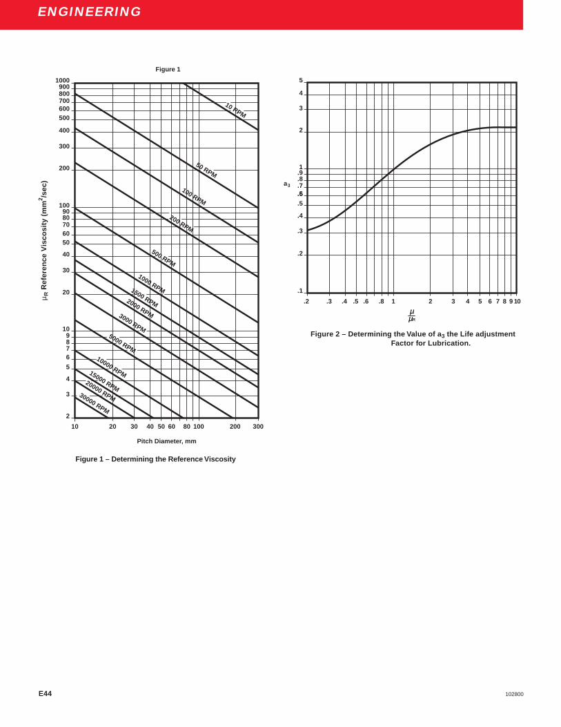
E44 102800
ENGINEERING
1000900800700600500
400
300
200
1009080706050
40
30
20
109876
5
4
3
2
30000 RPM
20000 RPM
15000 RPM
10000 RPM
5000 RPM
3000 RPM
2000 RPM
1500 RPM
1000 RPM
500 RPM
200 RPM
100 RPM
50 RPM
10 RPM
10 20 30 40 50 60 80 100 200 300
Pitch Diameter, mm
Figure 1
.1
.2
.3
.4
.5
.5.6
.7
.8
.91
2
3
4
5
a3
.2 .3 .4 .5 .6 .8 1 2 3 4 5 6 7 8 9 10
Figure 1 – Determining the Reference Viscosity
µµR
Figure 2 – Determining the Value of a 3 the Life adjustmentFactor for Lubrication.
µ R R
efer
ence
Vis
cosi
ty (
mm
2 /sec
)
µµR

E45102800
ENGINEERING
ApplicationsHigh-Speed Internal Grinding SpindleDesigned for internal precision grinding, this spindle incorpo-rates 2MM9106WO-CR superprecision bearings, preloadedby a nest of coiled helical springs mounted in a cartridge.Thrust load exerted by the springs assures intimate contact ofthe balls with the bearing raceways under all operatingconditions. The sealed construction provides highly effectiveprotection against intrusion of coolant and foreign matter.Grease, packed in each bearing prior to assembly, is sealed-in for life. Operating speed of this spindle is 25,000 rpm.
Ultra-Precision Surface Grinding Spindle2MMX9122WI-DUM superprecision bearings, produced toABEC-9 tolerances, are employed in this horizontal surfacegrinding spindle for maximum rigidity and accuracy. A back-to-back pair of 2MM312WI-CR-DUL superprecision bearingsare used as the floating location. This spindle grinds surfacesthat are accurate within .000025 inch, flat, parallel and squarewithin .000010 inch, and to a surface finish of 5 rms, or better.The spindle, driven by a 30 hp motor, operates at 900 rpm.Bearings are packed with grease prior to assembly.
Precision Surface Grinding SpindleThis motorized surface grinding spindle, operating at 3600rpm, uses 2MM9107WI-DUM duplex superprecisionpreloaded bearings at both locations, mounted back-to-back,with one pair floating. Labyrinth slinger-type sealing preventsentry of contaminants and seals in the lubrication. Bearingsare grease lubricated for life.
Heavy-Duty Precision Boring SpindleSuperprecision, duplexed, preloaded bearings mounted back-to-back are used at each location in this boring spindle toassure smooth performance and a high degree of radial andaxial rigidity. Operating speeds vary between 200 and 3000rpm. Equal-length spacers between the bearings at the work-end increase spindle rigidity. When the bearings are properlypositioned on the shaft and the respective rings securelyclamped, the preload is reproduced and no subsequentadjustment is required. Just prior to assembly, each bearing ispacked with grease for life.
Six-Spindle Automatic Screw MachineThis bearing arrangement meets the demand for a high-speed, heavy-duty, multiple-spindle screw machine to operatewith constant accuracy at maximum production. Because ofthe hollow shaft construction and the short distance betweenbearings, extra-light series duplex pairs are used at eachlocation. This affords a high degree of radial rigidity and addsstiffness to the shaft. By mounting a duplex pair of flanged(3MMF) bearing with a 2MM superprecision bearing, back-to-back, under a predetermined preload at the front end,accuracy and rigidity of the spindle are assured and permit astraight housing bore. The rear pair of back-to-back bearingsis allowed to float in the housing, making an outer-ring spacerunnecessary. Lubrication is by pressure-feed oil circulation.
EN
GIN
EE
RIN
G
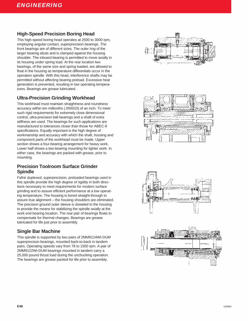
E46 102800
ENGINEERING
High-Speed Precision Boring HeadThis high-speed boring head operates at 2500 to 3000 rpm,employing angular-contact, superprecision bearings. Thefront bearings are of different sizes. The outer ring of thelarger bearing abuts and is clamped against the housingshoulder. The inboard bearing is permitted to move axially inits housing under spring load. At the rear location twobearings, of the same size and spring loaded, are allowed tofloat in the housing as temperature differentials occur in theoperation spindle. With this head, interference shafts may bepermitted without affecting bearing preload. Excessive heatgeneration is prevented, resulting in low operating tempera-tures. Bearings are grease lubricated.
Ultra-Precision Grinding WorkheadThis workhead must maintain straightness and roundnessaccuracy within ten millionths (.000010) of an inch. To meetsuch rigid requirements for extremely close dimensionalcontrol, ultra-precision ball bearings and a shaft of extrastiffness are used. The bearings for such applications aremanufactured to tolerances closer than those for ABEC-9specifications. Equally important is the high degree ofworkmanship and accuracy with which the shaft, housing andcomponent parts of the workhead must be made. Uppersection shows a four-bearing arrangement for heavy work.Lower half shows a two-bearing mounting for lighter work. Ineither case, the bearings are packed with grease, prior tomounting.
Precision Toolroom Surface GrinderSpindleFafnir duplexed, superprecision, preloaded bearings used inthis spindle provide the high degree of rigidity in both direc-tions necessary to meet requirements for modern surfacegrinding and to assure efficient performance at a low operat-ing temperature. The housing is bored straight-through toassure true alignment – the housing shoulders are eliminated.The precision ground outer sleeve is doweled to the housingto provide the means for stabilizing the spindle axially at thework end bearing location. The rear pair of bearings floats tocompensate for thermal changes. Bearings are greaselubricated for life just prior to assembly.
Single Bar MachineThis spindle is supported by two pairs of 2MM9124WI-DUMsuperprecison bearings, mounted back-to-back in tandempairs. Operating speeds vary from 78 to 1500 rpm. A pair of2MM9122WI-DUM bearings mounted in tandem carry a25,000 pound thrust load during the unchucking operation.The bearings are grease packed for life prior to assembly.
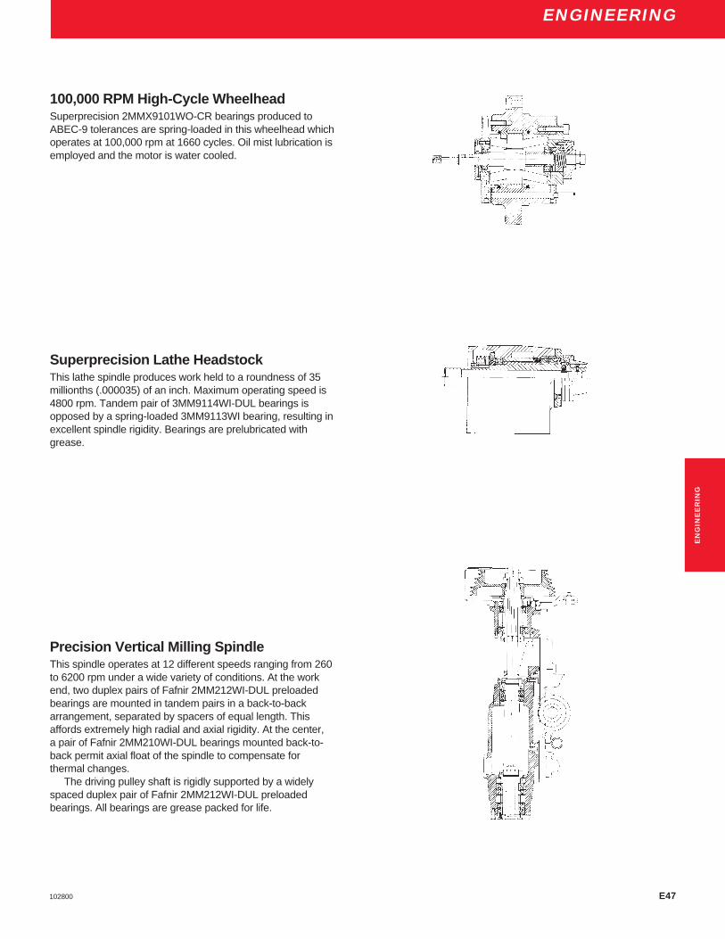
E47102800
ENGINEERING
100,000 RPM High-Cycle WheelheadSuperprecision 2MMX9101WO-CR bearings produced toABEC-9 tolerances are spring-loaded in this wheelhead whichoperates at 100,000 rpm at 1660 cycles. Oil mist lubrication isemployed and the motor is water cooled.
Superprecision Lathe HeadstockThis lathe spindle produces work held to a roundness of 35millionths (.000035) of an inch. Maximum operating speed is4800 rpm. Tandem pair of 3MM9114WI-DUL bearings isopposed by a spring-loaded 3MM9113WI bearing, resulting inexcellent spindle rigidity. Bearings are prelubricated withgrease.
Precision Vertical Milling SpindleThis spindle operates at 12 different speeds ranging from 260to 6200 rpm under a wide variety of conditions. At the workend, two duplex pairs of Fafnir 2MM212WI-DUL preloadedbearings are mounted in tandem pairs in a back-to-backarrangement, separated by spacers of equal length. Thisaffords extremely high radial and axial rigidity. At the center,a pair of Fafnir 2MM210WI-DUL bearings mounted back-to-back permit axial float of the spindle to compensate forthermal changes.
The driving pulley shaft is rigidly supported by a widelyspaced duplex pair of Fafnir 2MM212WI-DUL preloadedbearings. All bearings are grease packed for life.
EN
GIN
EE
RIN
G

E48 102800
ENGINEERING
Precision Jig-Boring SpindleThis jig-boring spindle delivers extreme accuracy over awide range of speeds. Excellently designed, it is supportedwith 2MM210WI-DUM grease-lubricated superprecisionBearings. With this spindle, holes located to an accuracy ofone ten-thousandth (.0001) of an inch are bore roundstraight and to size limits of better than two ten-thousandths(.0002) of an inch.
High Speed Motorized RouterA specially matched duplex pair of Fafnir 2MM210WI-DU-FS223 superprecision ball bearings, mounted back-to-back atthe work-end, affords the necessary bearing rigidity to permitrouting through aluminum plate one inch thick with a singlepass. The upper bearing is spring -loaded and permitted tofloat. Router is driven by a 30 hp motor at speeds up to15,000 rpm, and uses oil mist lubrication.

E49102800
ENGINEERING
Bearing H" Fit R" Fit P" Fit J" FitSize Snug regular Loose Extra-loose
(C2) (C0) (C3) (C4)
0.0000" µm 0.0000" µm 0.0000" µm 0.0000" µm00 1-3 3-8 2-5 5-13 4-8 10-20 7-10 18-2501 1-4 3-10 2-6 5-15 5-9 13-23 8-12 20-3002 1-4 3-10 2-6 5-15 5-9 13-23 8-12 20-3003 1-4 3-10 2-6 5-15 5-9 13-23 8-12 20-3004 1-4 3-10 3-7 8-18 6-10 15-25 9-13 23-33
05 1-4 3-10 3-7 8-18 6-10 15-25 10-15 25-3806 1-4 3-10 3-7 8-18 6-10 15-25 10-15 25-3807 1-4 3-10 3-7 8-18 7-12 18-30 12-17 30-4308 1-4 3-10 3-7 8-18 7-12 18-30 12-17 30-4309 1-4 3-10 3-8 8-20 8-13 20-33 13-19 33-48
10 1-4 3-10 3-8 8-20 8-13 20-33 13-19 33-4811 1-5 3-13 4-10 10-25 10-16 25-40 16-23 40-5812 1-5 3-13 4-10 10-25 10-16 25-40 16-23 40-5813 1-5 3-13 4-10 10-25 10-16 25-40 16-23 40-5814 1-5 3-13 5-11 13-28 11-19 28-48 19-27 48-68
15 1-5 3-13 5-11 13-28 11-19 28-48 19-27 48-6816 1-5 3-13 5-11 13-28 11-19 28-48 19-27 48-6817-20 1-6 3-15 5-13 13-33 13-22 33-55 22-32 55-8021-24 1-6 3-15 7-15 18-38 15-25 38-63 25-37 63-9325-28 2-8 5-20 8-18 20-45 17-31 43-79 29-50 74-127
VALUES SHOWN IN TEN-THOUSANDTHS INCHES (.0001") AND MICROMETERS ( µm)
The “R” fit is standard for M and V series bearings.
Radial Internal ClearanceDeep groove radial type bearings may be matched to variousradial internal clearances to meet specific design and perfor-mance requirements. The following chart lists the clearancesoptions available.
Conrad bearings ordered without a prefix for clearancespecification will be supplied with a “P” fit as standard.
EN
GIN
EE
RIN
G

102800E50

E51102800
MA
INT
EN
AN
CE
MA
CH
INE
TO
OL
SP
IND
LE
S
MAINTENANCE • MACHINE TOOL SPINDLES

E52 102800
ENGINEERINGMAINTENANCE • MACHINE TOOL SPINDLES
ForwardMachine tools must meet the ever-increasing demands ofmodern industry for faster speeds, greater accuracy,smoother finishes and higher production rates at minimumcosts. Such considerations are primarily influenced by themachine tool spindle with its superprecision ball bearings; andthe machine tool builder, the spindle maker, and the ballbearing manufacturer are all making great advances in theachievement of these goals.
The machine tool spindle is expertly designed. It isfabricated from the best materials with the utmost care.Quality and accuracy of machining and the rate of productiondepend greatly on the ball bearings that support the spindle.Spindle maintenance and servicing have become a matter ofprime importance and be done only by expert assemblers inmeticulously clean, well-lighted and constant temperaturesurroundings.
ProcedureIn this section the basic principles involved in the propermaintenance of machine tool spindles are outlined. Althoughthe servicing of a permanently grease-lubricated belt-driveninternal grinding wheelhead, Figure 1, is described, themounting techniques and installation procedures are typicalfor almost all types of ball bearing spindles.
Enclosed Dust-Free Working AreaThe desired results in the maintenance of machine toolspindles are achieved by an experienced mechanic workingin a well organized, clean, and enclosed area set apart fromthe manufacturing processes or machines that propagatedust-laden air. His work bench and tools are clean andmaintained in good working order. His surface plate isequipped with bench centers or parallel V-blocks andweighted end block, and test gage-blocks with 0.0001 inchdial indicators. He is equipped with outside and insidemicrometers, a hole gage with 0.0001 inch indicator, acomparator gage with 0.0001 inch indicator and master discsand rings or precision blocks.
To insure dimensional accuracy and proper fitting of thespindle parts and ball bearings, all checking and assemblyoperations should be performed with gages, parts, andbearings that have attained a constant temperature. Theequipment and all the parts to be assembled should be heldin the working area long enough for them to assume thermalequilibrium before any measurements are taken.
Inspection of Parts before AssemblyThe ideal shaft bearing seat is accurately and smoothlyground and absolutely free from burrs, tool marks and rust.An indicator gage that reads 0.0001 inch is used to check thebearing seat. This gage is set to the basic diameter with amaster disc or with precision blocks. Deviations from thestandard dimension are indicated by rolling the shaft back-ward and forward in several positions, and an axial movementof the bearing seat under the indicator gage registers anytaper.
Figure 1 – Internal Grinding Wheelhead

E53102800
ENGINEERINGMAINTENANCE • MACHINE TOOL SPINDLES
MA
INT
EN
AN
CE
MA
CH
INE
TO
OL
SP
IND
LE
S
The spindle shaft, with a steel ball located in one of itscenters, is then mounted on parallel V-blocks and heldagainst a weighted end block, Figure 2. Bench centers maybe used, provided the shaft centers are free of damage andtrue. With the dial indicator seen at the left set at zero andcontacting the bearing seat, the shaft is revolved slowly todetermine runout and straightness. Both seats should betrue with each other within 0.0002 inch total indicatorreading (TIR), and within 0.0001 inch for very high-speedspindles. The wheel-end and pulley taper of the shaft arechecked, and if the runouts do not coincide with therespective bearing seats, the high points of eccentricitiesare marked for identification. With the dial indicator seen atthe right in Figure 2, the squareness of the bearing shoul-ders on the shaft is ascertained. This runout should notexceed 0.0002 inch total indicator reading.
The housing bore is checked with a two- or three- pointhole gage which is set to the basic diameter with a masterring, or with precision blocks and a micrometer. By rockingthe gage in several positions in the housing bore, any out-of-roundness and deviation of diameter is indicated. Todiscover any existing taper, the gage is moved axially.Housing bores are held within specified limits and checkedfor finish and freedom from burrs and tool marks.
Spacers, locknuts, and slingers carefully inspected, andall burrs are removed to insure proper seating of the ballbearings. Faces of spacers A and B, Figure 1, and slingersC and D must be flat and parallel within 0.0002 inch andsquare with their bores. The inner-ring and outer-ringspacers should be equal in length within 0.0002 inch.
Prior to assembly, all parts of the wheelhead, Figure 3,including housing bores are cleaned thoroughly with asolvent such as Varsol and then carefully wiped with aclean, lint-free cloth. All dirt must be removed from threads,keyways, grooves, and splines. To prevent corrosion, allparts, including shaft bearing seats and shoulders as wellas the housing bores, are wiped with grease, leaving only athin, protective film.
Each Bearing Packed withThree Grams of GreaseFor this particular installation two pairs of 35mm bore, lightseries, angular -contact, duplexed superprecision ball bearingsare used. In unpackaging, care is taken to prevent the entry ofdirt or moisture into the bearings. The light protective oil put inthe bearing by the manufacturer is removed with Varsol. Eachbearing is carefully packed with about three grams of clean,suitable, ball bearing grease, using a flat steel scale forinserting the grease in to the bearing and around the balls.Grease voids within the bearing are eliminated, and evendistribution of the grease is accomplished by revolving thebearing slowly in the hands until the torque throughout thebearing becomes noticeably constant.
Bearings Assembled in Spindle MountingProper shaft and housing mounting fits must be establishedand maintained in the application of ball bearings. Generally,for machine tool spindles, the ball bearing should have a line-to-line fit with the shaft bearing seat and a sliding push fit in thehousing bore. Before the actual assembly operations begin, theball bearings may be used for trial purposes to insure thedesired mounting fits at final assembly. Damage to the ballbearings is avoided by taking care to mount bearings withoutcocking and to apply a firm hand pressure to the inner-ring facewhen placing the bearing on the shaft. Only thumb pressure isapplied to the face of the outer ring when the bearing is pushedinto the housing. Each bearing should be earmarked for itseventual position in the spindle assembly, making certain thatthe floating or spring-loaded bearings are slightly looser in thehousing than the front or fixed bearings.
At the wheel-end or nose of the spindle, the minimumhousing bore dimension for the fixed superprecision ballbearings may be established as 0.0001 inch less than themaximum outside diameter of the bearing. If the bearingoutside diameter tolerance is 0.0002 inch, the maximumhousing bore dimension is established at 0.0004 inch largerthan the minimum housing bore.
Figure 2 – Inspection of Shaft Figure 3 – Wheelhead Parts
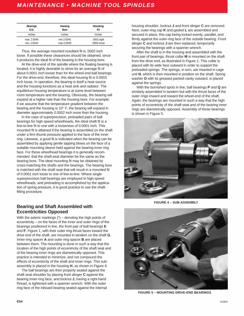
E54 102800
ENGINEERING
housing shoulder, locknut J and front slinger C are removed.Next, outer-ring cap K and gasket L are assembled andsecured in place, this cap being locked evenly, parallel, andfirmly against the outer-ring face of the outside bearing. Frontslinger C and locknut J are then replaced, temporarilysecuring the bearings with a spanner wrench.
After the shaft is in the housing and assembled with thefront pair of bearings, thrust collar M is mounted on the shaftfrom the drive end, as illustrated in Figure 1. This collar isplaced with its wide face outward in order to support thepreloaded springs. The springs, in turn, are inserted in cageunit N, which is then mounted in position on the shaft. Springwasher O with its greased packed cavity outward, is placedagainst the springs.
With the burnished spots in line, ball bearings P and Q aresimilarly assembled in tandem but with the thrust faces of theouter rings inward and toward the wheel-end of the shaft.Again, the bearings are mounted in such a way that the highpoints of eccentricity of the shaft seat and of the bearing innerrings are diametrically opposed. Assembly of these bearingsis shown in Figure 5.
MAINTENANCE • MACHINE TOOL SPINDLES
Thus, the average mounted resultant fit is .0002 inchloose. If possible these clearances should be obtained, sinceit produces the ideal fit of the bearing in the housing bore.
At the drive-end of the spindle where the floating bearing islocated, it is highly desirable to strive for an average fit ofabout 0.0001 inch looser than for the wheel-end ball bearings.For the drive-end, therefore, this ideal housing fit is 0.0003inch loose. In operation, the bearing is itself a heat sourceand the housing functions as a heat sink and radiator. Theequilibrium housing temperature is at some level betweenroom temperature and the bearing. Obviously, the bearing willexpand at a higher rate than the housing bore. For example:if we assume that the temperature gradient between thebearing and the housing is 10° F, the bearing will expand indiameter approximately 0.0002 inch more than the housing.
In the case of superprecision, preloaded pairs of ballbearings for high-speed wheelheads, the ideal shaft fit is aline-to-line fit to one with a looseness of 0.0001 inch. Thismounted fit is attained if the bearing is assembled on the shaftunder a firm thumb pressure applied to the face of the innerring. Likewise, a good fit is indicated when the bearing can beassembled by applying gentle tapping blows on the face of asuitable mounting sleeve held against the bearing inner ringface. For these wheelhead bearings it is generally recom-mended that the shaft-seat diameter be the same as thebearing bore. The ideal mounting fit may be obtained bycross-matching the shafts and the bearings. The bearing boreis matched with the shaft seat that will result in a mounted fitof 0.0001 inch loose to one of line-to-line. Where singlesuperprecision ball bearings are employed in high-speedwheelheads, and preloading is accomplished by the applica-tion of spring pressure, it is good practice to use the shaft-fitting procedure.
Bearing and Shaft Assembled withEccentricities OpposedWith the asteric markings (*) – denoting the high points ofeccentricity – on the faces of the inner and outer rings of thebearings positioned in line, the front pair of ball bearings Eand F, Figure 1, with their outer ring thrust faces toward thedrive end of the shaft, are mounted in tandem on the shaft G.Inner-ring spacer A and outer ring spacer B are placedbetween them. The mounting is done in such a way that thelocation of the high points of eccentricity of the shaft seat andof the bearing inner rings are diametrically opposed. Thispractice is intended to minimize, and not compound theeffects of eccentricity of the shaft and inner rings. This sub-assembly is placed in the housing H, as shown in Figure 4.
The ball bearings are then properly seated against theshaft seat shoulder by placing front slinger C against thebearing inner-ring face, and locknut J, having a right-handthread, is tightened with a spanner wrench. With the outerring face of the inboard bearing seated against the internal
Bearings Housing MountingO.D. Bore Fit
inches inches inches
max. 2.8346 min.2.8345 .0001 tightmin. 2.8344 max.2.8349 .0005 loose
FIGURE 4 – SUB-ASSEMBLY
FIGURE 5 – MOUNTING DRIVE-END BEARINGS

E55102800
ENGINEERING
MA
INT
EN
AN
CE
MA
CH
INE
TO
OL
SP
IND
LE
S
MAINTENANCE • MACHINE TOOL SPINDLES
After closure cap R is securely fastened to the housing,rear slinger D is placed in position against the inner-ring faceof the ball bearing, and locknut S, having a left-hand thread, isscrewed on the shaft with a spanner wrench handle with twosharp raps of a light hammer. The procedure is repeated fromthe opposite side by relocating the spanner wrench on thelocknut 180° from the first position. The clearance betweenthe closure cap R and the rear slinger D is checked with afeeler gage to make sure that no interference exists betweenthe two parts.
Front locknut J is loosened counterclockwise about fourturns and indicator readings taken at the wheel-end of theshaft, Figure 6,. If these readings correspond to the noserunout or eccentricity previously obtained when the shaft wasinspected on parallel V-blocks before assembly, no inaccura-cies have been introduced through installation of the bearing.Following the check, the front locknut J is screwed on theshaft until the face of the front slinger C comes to bear on theinner ring face of the ball bearing. This locknut is set with aspanner wrench to tighten the bearing inner rings togetherand against the shaft shoulder, Figure 7. Tightening is doneevenly and securely by striking the wrench handle with twosharp raps of a light hammer and repeating this operation onthe other side of the locknut, 180° from the first position.Approximately the same force should be used in tighteningthe locknut every time it is tightened. This is important,especially during the trial and error scraping process.
Once these bearings are locked by the locknut, theybecome a preloaded pair in a fixed position, and the spindle ischecked for possible runout. Should runout now exist in theassembly, it can be attributed directly to the relation betweenthe threads and the locking face of the locknut. If the shaftshows a runout of 0.0001 inch or more, it can be assumedthat the trouble lies in the locknut contact with the outwardface of the front slinger. If the locknut face is tightened againstthe bearing inner face without the locknut face being squarewith the threaded bore of the shaft, the shaft may be forced tobend. This shaft bending will cause a radial eccentricity(runout) as measured on the shaft. Scraping of the high pointson the locknut face will eliminate this out-of-squarenesscondition and provide optimum running accuracy.
Scraping Locknut to Eliminate RunoutTo determine where to scrape, first check with an indicatorover the front end of the shaft at point X, Figure 1, until thehighest reading is noted. This shows that the tip of theindicator point is directly over the vertical diameter of theshaft. Stopping at the highest reading on the indicator, theshaft is slowly rotated from the opposite end of the spindlewhich, in this case, would be the drive or rear end. Stop at thelowest reading on the indicator dial and with a red pencil ormetal-marking pencil scribe a line longitudinally along theshaft and on the outside diameter of the locknut J directly inline with the low reading.
Figure 6 – Checking Nose-End Runout
Figure 7 – Tightening with Spanner Wrench
E56 102800
ENGINEERING
The locknut is removed from the assembly and the linetransferred to its front face. This procedure locates the area tobe scraped or lapped.
Scraping may be done with a scraping tool on the highsurface and approximately 90° on both sides. Care should betaken to scrape evenly and uniformly. The depth of scraping(which will always be slight) can be judged only by theamount of runout shown on the indicator dial.
When the estimated amount of metal has been removedby scraping, the locknut is washed and blown clean. It is thenplaced against the face of the front slinger and tightened. Newreadings are taken, and if the runout persists, the locknut isremoved and scraped in the same manner. If scraping on thesame surface area is necessary, it is obvious that not enoughmetal was removed the first time. If the high surface isdiagonally opposite, too much metal was removed. Scrapingis continued until the face shows a very close reading on theindicator. To determine and correct any inaccuracies thatmight exist at the drive-end of the spindle, indicator readingsare taken at point Y, Figure 1. After locknut S is loosenedclockwise and removed, the same basic procedures used forthe wheel end of the spindle are followed. The wheelheadassembly is then ready for the run-in test and final inspection.
Checking Temperature,Vibration and RoughnessBefore starting the test run for final inspection, the spindle isstarted and stopped a few times to make sure the wheelheadand testing equipment are in good working order. The spindleis then brought up to operational speed, which should notexceed the maximum speed indicated on the nameplate.
Temperature readings are taken as close to the bearingsas possible, every five minutes at first, for each bearing on thehousing. If the wheelhead heats up rapidly, it is stopped,allowed to cool to room temperature, and then re-started.Readings are then taken about every fifteen minutes until thetemperature levels off, The wheelhead should not be permit-ted to run hotter than 50° above room temperature or to runso that the heat becomes unbearable to the touch. Generally,temperature readings of more than 120°F are not encoun-tered. Three to four hours should be reasonable time forrunning-in the wheelhead and checking for temperatures,unusual sounds, vibration, and roughness. Following thesuccessful completion of this test, the precision-builtwheelhead is ready for use in the manufacturing area.
CleanlinessElaborate precautions are taken to insure that superprecisionball bearings are dirt-free and thoroughly protected whenpackaged. Extreme care should be exercised to keep themclean and away from moisture and contamination from thetime they are unpackaged until they are mounted in spindlesand running.
In servicing machine tool spindles, cleanliness cannot beoveremphasized. THe work area, bench and tools should beclean and well organized. Clean hands are necessary, too.Plenty of clean lint-free rags should be available to keep thehands free of moisture, grime and dust-gathering oil. Thespindle parts should be washed thoroughly in cleaningsolution and dried with a filtered air under pressure.In additionto the spindle parts, the inside of the housing and all oil holesand threads should be solvent cleaned and air dried. Anycorrosion on the shaft should be carefully removed. This isdone by stoning or with crocus cloth while rotating the shaftand must be done carefully to avoid polishing the shaftundersize. These operations are followed with solventcleaning and air drying.
Varsol with a 10% oil mixture is a good grade of non-flammable cleaning solution and an excellent cleansingagent. Chlorinated solvents such as tetrachloride aredefinitely not recommended for this purpose.
Freshly unpackaged bearings that are to be in oil or oilmist lubricated in spindles need not be cleaned of theirprotective oil. Bearings that are grease packed at ourfactories should be used as received.
Often times, the user packs bearings with grease prior tomounting. In such cases, the original protective oil slush isremoved from the bearings with Varsol, and the bearings aredried with air under pressure by holding the bearing firmly sothat spinning is avoided. Clean grease of the correct typeshould be packed carefully into the bearings in recommendedquantities.
MAINTENANCE • MACHINE TOOL SPINDLES

E57102800
ENGINEERING
In servicing machine tool spindles it is essential toanalyze the operating troubles and probable causes of theimproper performance or malfunctions of the spindle,especially if the ball bearings have failed prematurely.
Causes and conditions that indicate or lead to ball bearingreplacement are:
Out-of-roundness of work;
Impossibility of maintaining tolerances;
Existence of noise and chatter;
Production of rough or poor finishes;
Accidental damage to machine spindle;
“Brinelling” of bearings;
Entry of coolant and contamination into bearings;
Faulty lubrication of bearings.
Before the spindle is removed from the machine, a checkshould be made to ascertain whether the trouble is with thespindle and the bearings or the result of improper tooling,roughness in the machine slides, irregular feeds or someother such cause.
When the cause of damage or failure of ball bearings isnot immediately apparent, there is a tendency to suspectfaulty bearing materials or defective workmanship in theproduct; but the materials and the manufacturing methodsin the production of ball bearings, through many years ofresearch, have reached such a state of refinement thatdefects in bearings are extremely remote. In most cases,ball bearings fail from preventable causes, such as faultymounting practice, incorrect shaft and housing mountingfits, improper or unsuitable lubrication and intrusion offoreign matter.
Bearing replacements without corrective measures oftenresult in the repetition of the trouble. It becomes veryimportant, therefore, to determine accurately and completely,the cause of the improper functioning of the ball bearings.
Ball bearings should be pressed onto a shaft with themounting force applied only to the inner ring. Similarly, whenbearings are mounted in a housing, the mounting forceshould be applied solely to the outer ring. Mounting dents or‘brinells’ high on the raceway are caused when the mountingforce is applied to a ring which is not being mounted. Theyshould be seated solidly against the shoulders by means ofan arbor press and a tubular drift. It is important that bothends of the tube are faced square and that all corners arebroken to avoid flaking. The tubes must be clean and freefrom scale, both inside and out, to avoid the possibility of dirtfalling into the bearings.
In mounting ball bearings, particular attention should begiven to the mounting fits. If the bearing seat is of the correctdiameter and without serious taper, the bearing can be
pressed to the shoulder with a uniform pressure. However, ifthe bearing sticks and requires excessive force at any point, itmay have been cocked . Continued pressure on the bearingring that was not squarely is likely to scrape and seriouslydamage the bearing seat. The source of trouble, which canbe a burred or tapered seat, should be determined andcorrected before proceeding.
Fretting corrosion in the bearing bore can be the result ofloose shaft fits. This action produces iron oxide causing freeiron to be removed from the shaft. This material gets into thebearing and being abrasive causes wear in the bearing,produces noise and engenders premature bearing failure.
Misaligned bearings can be the cause of early fatiguefailures. Bearing misalignment can be caused by housingbores that are not in line with each other or when the bearingseats on the shaft are not concentric. Bearings may alsobecome misaligned if the shaft or housing shoulder is out-of-square. When considerable misalignment is present, the loadtrack veers from one side of the raceway to the other. Highlymisaligned loads could force the balls over the edge of theraceway shoulder, causing the ball surfaces to be creasedand resulting in premature fatigue failures.
Foreign matter – coolant, dust, dirt or other contaminants –pressed to ball bearings is the most common cause ofbearing failure. Such a condition may be caused either by theentry of dirt or moisture, by the improper handling of thebearing during the mounting procedure or from inadequatesealing of the shaft and housing. Severe cases may causeabrasion and wear of the revolving parts, generally resultingin excessive axial looseness in the bearing. Visual evidenceof this would be dull, gray discoloration of the raceways andthe balls. Under such conditions ball bearings become noisyand inevitably fail to perform satisfactorily.
Lubrication is essential for the proper operation of ballbearings. Greases and oils are both used over a considerablerange of speeds and operating temperatures. The choice oflubrication should be made after the careful consideration ofthe factors involved.
Generally, ball bearings operating at moderate speedsrequire relatively small amounts of lubrication. Too muchlubrication, accompanied by churning and excessive torque,is manifested by temperature rise and intense over-heating.Lack of lubrication causes a rise in operating temperature,coupled with a whistling sound when running. Unless suchconditions are corrected, the rings, balls and cage may beseriously damaged. Discoloration of the bearing parts isevidence of excessive operating temperatures. M
AIN
TE
NA
NC
E M
AC
HIN
ET
OO
L S
PIN
DL
ES
MAINTENANCE • MACHINE TOOL SPINDLES

E58 102800
ENGINEERINGMAINTENANCE • MACHINE TOOL SPINDLES
In taking corrective measures it is important to know theoperating history of the spindle and to study a cross-sectionaldrawing of the mounting arrangement. This informationshould include the following:
Operational speed
Operating temperature
Type of lubrication
Estimate of working loads
Type of drive and horsepower
Material processed
Reason for spindle failure
In addition and before the spindle is disassembled, therunout of the spindle nose should be determined with a0.0001 inch indicator and recorded. The bearings should beremoved carefully, without further damage, and tagged 1, 2,3, 4, etc. starting from the work-end of the spindle. Pairs ofbearings should be marked DB, DF or DT to denote whetherthe bearings had been mounted back-to-back, face-to-face, orin tandem. The conditions of the bearings should be noted forthe entry of foreign matter, lack of lubrication, excessivetemperatures and the extent of damage.
Before bearing replacement is made, the spindle partsshould be thoroughly cleaned with Varsol and measuredcarefully for wear in the housing bores and shaft seats.Housing and shaft shoulders should be checked for equallengths and parallelism of faces. All mating parts should befree of nicks and burrs.
Typical applications of precision ball bearings to machinetool spindles, showing bearing bore sizes, speed range, typeof lubrication and approximate operating temperature, aretabulated at the bottom of this page.
In their efforts to attain even smoother and finer surfacefinishes, many users of high-speed wheelheads, especially ofthe belt driven type, operate their spindles at higher speedsthan those for which they were designed. Spindle failure oftenoccurs due to the rise in operating temperature caused by thebreakdown of the lubricant, and because the original springpreload on the bearings was not reduced to correspond withthat recommended for the increased speed. In such cases,the induced heat expands the internal parts of the spindle,thereby tightening the mounting fits and preventing thefloating of spring loaded bearings from moving axially. Thus,additional heat is generated and failure results. Wheelheadusers are cautioned to consult the original equipmentmanufacturer when increased speeds for their spindles arecontemplated.
Many factors are involved in the design, fabrication anduse of high speed spindles. Among them are the selection ofthe ball bearings, the amount of applied preloading, themounting fits, the accuracy of the parts and the skill withwhich they are assembled, the operating temperature andspeed involved, and lastly, the type of lubricant - grease, oil,or oil mist. Adequate lubrication, low operating temperatures,accurate and smooth operation, low friction, and a highdegree of axial and radial rigidity are all extremely importantqualities for successful machine tool spindle performance.The attainment of these qualities will continue to require thecooperation of the ball bearing manufacturer and the machinetool builder, as well as the machine tool user.
TYPICAL APPLICATIONS OF BALL BEARINGS TO MACHINE TOOL SPINDLES
Application Bearing Bore, mm Speed Range, rpm Lubrication Approximate OperatingDegrees F.
Cylindrical and Internal GrindersWheelheads
Belt Drive 17-50 Up to 100,000 Oil mist- grease-oil 100-120High-Frequency motor Drive 8-50 10,000-150,000 Oil mist- grease 95-120
Workheads Wide Range Up to 5,000 Grease 95-110
Surface Grinders Wide Range 1,800-6,000 Grease 110Tool and Cutter Grinders 20-35 5,000-10,000 Grease 100-115Gear and Thread Grinders 60-80 3,000 - 5,000 Grease 100-115
Boring Heads Wide Range Up to 10,000 Oil mist-grease-oil 105-120Jig Bores 25-75 Up to 3,000 Grease 85-100Lathes Wide Range Up to 10,000 Oil-grease 100-120
Drilling Machines 15-40 Up to 30,000 Oil-grease 100-115Milling Machines Wide Range Up to 12,500 Oil mist-grease-oil 100-115Routers 20-60 12,000-30,000 Oil mist-grease 110-125
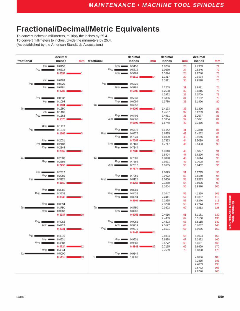
E59102800
ENGINEERING
1.0236 261.0630 271.1024 281.1417 291.1811 30
1.2205 311.2598 321.2992 331.3386 341.3780 35
1.4173 361.4567 371.4961 381.5354 391.5748 40
1.6142 411.6535 421.6929 431.7323 441.7717 45
1.8110 461.8504 471.8898 481.9291 491.9685 50
2.0079 512.0472 522.0866 532.1260 542.1654 55
2.2047 562.2441 572.2835 582.3228 592.3622 60
2.4016 612.4409 622.4803 632.5197 642.5591 65
2.5984 662.6378 672.6772 682.7165 692.7559 70
2.7953 712.8346 722.8740 732.9134 742.9528 75
2.9921 763.0315 773.0709 783.1102 793.1496 80
3.1890 813.2283 823.2677 833.3071 843.3465 85
3.3858 863.4252 873.4646 883.5039 893.5433 90
3.5827 913.6220 923.6614 933.7008 943.7402 95
3.7795 963.8189 973.8583 983.8976 993.9370 100
4.1339 1054.3307 1104.5276 1154.7244 1204.9213 125
5.1181 1305.3150 1355.5118 1405.7087 1455.9055 150
6.1024 1556.2992 1606.4691 1656.6929 1706.8898 175
7.0866 1807.2835 1857.4803 1907.6772 1957.8740 200
33⁄64 0.515617⁄32 0.5312
35⁄64 0.54690.5512 14
9⁄16 0.562537⁄64 0.5781
0.5906 15
19⁄32 0.593839⁄64 0.6094
5⁄8 0.62500.6299 16
41⁄64 0.640621⁄32 0.6562
0.6693 17
43⁄64 0.671911⁄16 0.6875
45⁄64 0.70310.7087 18
23⁄32 0.718847⁄64 0.7344
0.7480 19
3⁄4 0.750049⁄64 0.7656
25⁄32 0.78120.7874 20
51⁄64 0.796913⁄16 0.8125
0.8268 21
53⁄64 0.828127⁄32 0.8438
55⁄64 0.85940.8661 22
7⁄8 0.875057⁄64 0.8906
0.9055 23
29⁄32 0.906259⁄64 0.9219
15⁄16 0.93750.9449 24
61⁄64 0.953131⁄32 0.9688
0.9843 25
63⁄64 0.98441 1.0000
1⁄64 0.01561⁄32 0.0312
0.0394 1
3⁄64 0.04691⁄16 0.0625
5⁄64 0.07810.0787 2
3⁄32 0.09387⁄64 0.1094
0.1181 31⁄8 0.1250
9⁄64 0.14065⁄32 0.1562
0.1575 4
11⁄64 0.17193⁄16 0.1875
0.1969 5
13⁄64 0.20317⁄32 0.2188
15⁄64 0.23440.2362 6
1⁄4 0.250017⁄64 0.2656
0.2756 7
9⁄32 0.281219⁄64 0.2969
5⁄16 0.31250.3150 8
21⁄64 0.328111⁄32 0.3438
0.3543 9
23⁄64 0.35943⁄8 0.3750
25⁄64 0.39060.3937 10
13⁄32 0.406227⁄64 0.4219
0.4331 11
7⁄16 0.437529⁄64 0.4531
15⁄32 0.46880.4724 12
31⁄64 0.48441⁄2 0.5000
0.5118 13
decimal decimal decimal decimalfractional inches mm fractional inches mm inches mm inches mm
Fractional/Decimal/Metric EquivalentsTo convert inches to millimeters, multiply the inches by 25.4.To convert millimeters to inches, divide the millimeters by 25.4.(As established by the American Standards Association.)
MA
INT
EN
AN
CE
MA
CH
INE
TO
OL
SP
IND
LE
SM
AIN
TE
NA
NC
E M
AC
HIN
ET
OO
L S
PIN
DL
ES
MAINTENANCE • MACHINE TOOL SPINDLES

E60 102800
ENGINEERING
For Ball Screw Support Bearings Only:
*Procedure for making a Quad Set from two sets ofDuplex Bearings.
1. Physically remove the bearings from their boxes
2. Without removing the bearings from their plastic bags,locate the laser marked code on the outer ring (O.D.).The marking will be a single letter. There are fourpossible letters, either “A, B, C, or D”.
Quick ReferenceData Sheets
Note: There are two possible combinations of marking thatcan be on the outer rings of a DUPLEX set of bearings. Onecombination is having one bearing marked with an “A” and theother with a “D”. The second combination is having onebearing marked with a “B” and the other with a “C”.
3. Locate two sets of DUPLEX bearings (four bearingstotal) marked with “A” and “D” or two sets of bearingsmarked with “B” and “C”.
4. Quad Sets should be matched according to one of thefollowing configurations.
or
A A D D D D A A
II. Having two sets of bearings that are marked “B”, “C”.Match as shown below.
I. Having two sets of bearings that are marked “A”, “D”.Match as shown below.
or
B B C C C C B B
MAINTENANCE • MACHINE TOOL SPINDLES
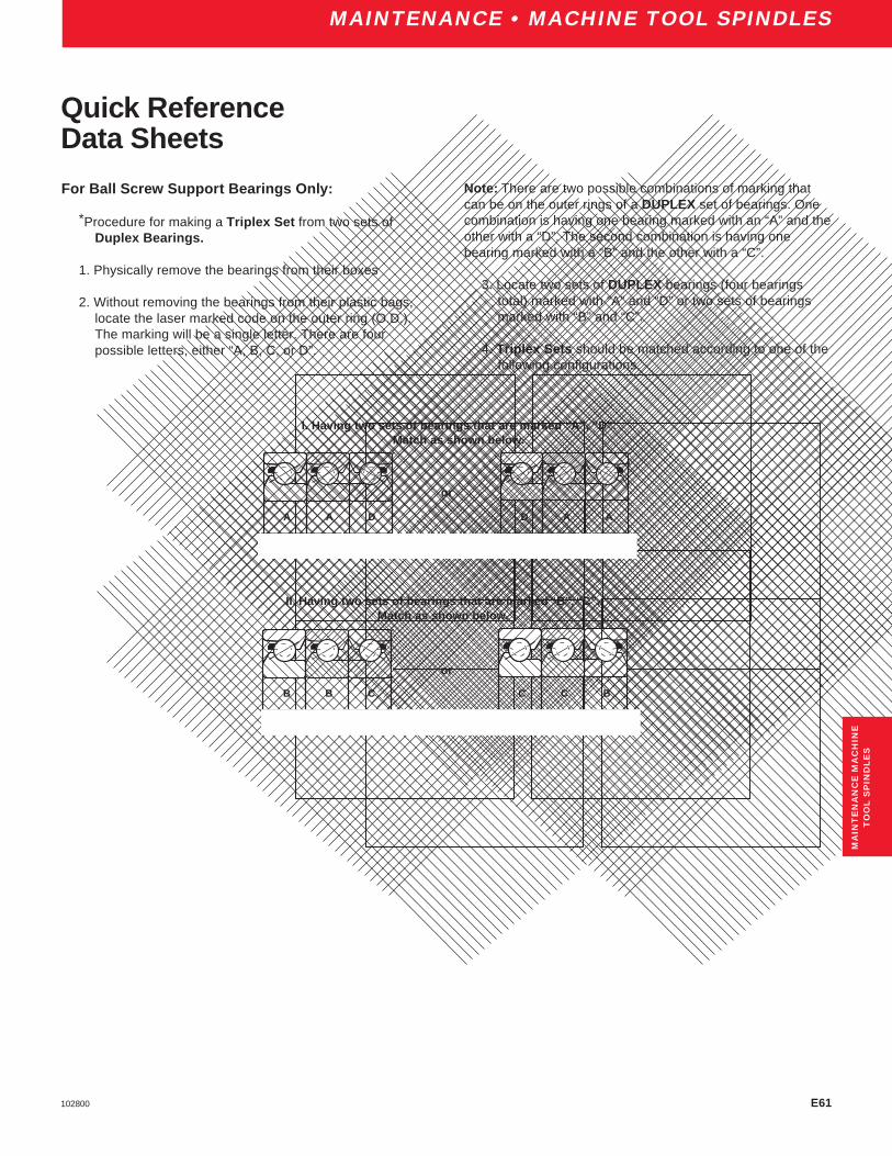
E61102800
ENGINEERING
For Ball Screw Support Bearings Only:
*Procedure for making a Triplex Set from two sets ofDuplex Bearings.
1. Physically remove the bearings from their boxes
2. Without removing the bearings from their plastic bags,locate the laser marked code on the outer ring (O.D.).The marking will be a single letter. There are fourpossible letters, either “A, B, C, or D”.
Quick ReferenceData Sheets
I. Having two sets of bearings that are marked “A”, “D”.Match as shown below.
Note: There are two possible combinations of marking thatcan be on the outer rings of a DUPLEX set of bearings. Onecombination is having one bearing marked with an “A” and theother with a “D”. The second combination is having onebearing marked with a “B” and the other with a “C”.
3. Locate two sets of DUPLEX bearings (four bearingstotal) marked with “A” and “D” or two sets of bearingsmarked with “B” and “C”.
4. Triplex Sets should be matched according to one of thefollowing configurations.
or
A A D D A A
or
B B C C C B
II. Having two sets of bearings that are marked “B”, “C”.Match as shown below.
MA
INT
EN
AN
CE
MA
CH
INE
TO
OL
SP
IND
LE
S
MAINTENANCE • MACHINE TOOL SPINDLES

E62 102800
ENGINEERING
For Ball Screw Support Bearings Only:
*Procedure for making a Duplex Set from one Quad set ofbearings.
1. Physically remove the bearings from their box(es).
2. Without removing the bearing from the plastic bags,locate the laser “V,, mark and the laser marked codeon the outer ring (O.D.). The laser “V” mark on theO.D. of the quad set is used to orient the bearings in aback-to-back configuration. The laser mark code willbe a single letter. There are four possible letters,either “A, B, C, or D”.
Quick ReferenceData Sheets
Note: There are two possible combinations of markings thatcan be on the outer rings of a QUAD set of bearings. Onecombination is having the two bearings in tandem markedwith an “A” opposed by two bearings in tandem marked witha “D” . The second combination is having two bearings intandem marked with a “B” opposed by two bearings intandem marked with a “C”. Refer to possible combinationsbelow.
3. Duplex Sets should be matched according to thefollowing procedure.
The two outer bearings should be paired together to formone set of duplex bearings and the two inner bearingswill form the other pair.
or
A A D D B B C C
or
A D A D
(example)
MAINTENANCE • MACHINE TOOL SPINDLES
or
B C B C
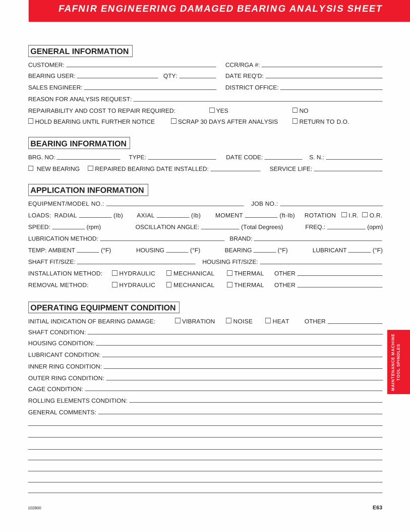
E63102800
ENGINEERING
GENERAL INFORMATION
CUSTOMER: CCR/RGA #:
BEARING USER: QTY: DATE REQ’D:
SALES ENGINEER: DISTRICT OFFICE:
REASON FOR ANALYSIS REQUEST:
REPAIRABILITY AND COST TO REPAIR REQUIRED: YES NO
HOLD BEARING UNTIL FURTHER NOTICE SCRAP 30 DAYS AFTER ANALYSIS RETURN TO D.O.
BEARING INFORMATION
BRG. NO: TYPE: DATE CODE: S. N.:
NEW BEARING REPAIRED BEARING DATE INSTALLED: SERVICE LIFE:
APPLICATION INFORMATION
EQUIPMENT/MODEL NO.: JOB NO.:
LOADS: RADIAL (Ib) AXIAL (Ib) MOMENT (ft-Ib) ROTATION I.R. O.R.
SPEED: (rpm) OSCILLATION ANGLE: (Total Degrees) FREQ.: (opm)
LUBRICATION METHOD: BRAND:
TEMP: AMBIENT (°F) HOUSING (°F) BEARING (°F) LUBRICANT (°F)
SHAFT FIT/SIZE: HOUSING FIT/SIZE:
INSTALLATION METHOD: HYDRAULIC MECHANICAL THERMAL OTHER
REMOVAL METHOD: HYDRAULIC MECHANICAL THERMAL OTHER
OPERATING EQUIPMENT CONDITION
INITIAL INDICATION OF BEARING DAMAGE: VIBRATION NOISE HEAT OTHER
SHAFT CONDITION:
HOUSING CONDITION:
LUBRICANT CONDITION:
INNER RING CONDITION:
OUTER RING CONDITION:
CAGE CONDITION:
ROLLING ELEMENTS CONDITION:
GENERAL COMMENTS:
MA
INT
EN
AN
CE
MA
CH
INE
TO
OL
SP
IND
LE
S
FAFNIR ENGINEERING DAMAGED BEARING ANALYSIS SHEET

E64 102800
ENGINEERINGINDEX
A PageABEC Tolerances,Introduction . . . . . . . . . . . . . . . . . . . . . . . . . . E3ABEC-7 Description . . . . . . . . . . . . . . . . . . . . . . . . . . . . . . . . . . . 10ABEC-7 Housing Mounting Fits . . . . . . . . . . . . . . . . . . . . . E10-E15ABEC-7 Shaft Mounting Fits . . . . . . . . . . . . . . . . . . . . . . . . E8, E9ABEC-7,-9 Standard Tolerances Inner and Outer Rings . . . E4, E5ABEC-9 Description . . . . . . . . . . . . . . . . . . . . . . . . . . . . . . . . . . . 10ABMA/ISO Symbols – Inner Ring . . . . . . . . . . . . . . . . . . . . . . . E4ABMA/ISO Symbols – Outer Ring . . . . . . . . . . . . . . . . . . . . . . . E5Angular Contact Bearings, Introduction . . . . . . . . . . . . . . . . . . . . 12Applications . . . . . . . . . . . . . . . . . . . . . . . . . . . . . . . . . . . . E45-E48
BBack-To-Back vs Face-To-Face Mounting . . . . . . . . . . . . . . . . E30Ballscrew Support Bearings . . . . . . . . . . . . . . . . . . . . . . . . . 87-100Ballscrew Support Bearings, Introduction . . . . . . . . . . . . . . . . . . 13Ballscrew Support Bearings, Nomenclature Chart . . . . . . . . . . . . 86Ballscrew Support Bearings, Shaft and Housing Shoulder Dimensions . . . . . . . . . . . . . . . . . . . . . . . . . . . . . . . E16Bearing Locknuts . . . . . . . . . . . . . . . . . . . . . . . . . . . . . . . . . . . E35Bearing Selection . . . . . . . . . . . . . . . . . . . . . . . . . . . . . . . . . . E32Bearing Spacers . . . . . . . . . . . . . . . . . . . . . . . . . . . . . . . . . . . E34Bearing and Shaft Assembled with Eccentricities Opposed . . . E54Bearings Assembled in Spindle Mounting . . . . . . . . . . . . . . . . E53
CChecking Spindle Temperature, Vibration, Roughness . . . . . . E56Cleanliness . . . . . . . . . . . . . . . . . . . . . . . . . . . . . . . . . . . E56, E57Conditions of Sale . . . . . . . . . . . . . . . . . . . . . . . . . . . . . . . . . . . . . 5
DDistribution Service Centers . . . . . . . . . . . . . . . . . . . . . . . . . . E66Drip Feed Oil Lubrication . . . . . . . . . . . . . . . . . . . . . . . . . . . . . E38Dynamic Load Rating . . . . . . . . . . . . . . . . . . . . . . . . . . . E41, E42
EEngineering . . . . . . . . . . . . . . . . . . . . . . . . . . . . . . . . . . . . . E1-E49Engineering,Forward . . . . . . . . . . . . . . . . . . . . . . . . . . . . . . . . . E2Engineering Notations . . . . . . . . . . . . . . . . . . . . . . . . . . . . . . . E41Engineering Sales Offices and Distribution Service Centers . . E66Equivalency Tables . . . . . . . . . . . . . . . . . . . . . . . . . . . . . . . . . E59Ex-Cell-O Spindle Bearings . . . . . . . . . . . . . . . . . . . . . . . . . . . . . 79Extended Basic Dynamic Load Rating . . . . . . . . . . . . . . . E41, E42Extra-Light 2MM9100WI, 3MM9100WI Series . . . . . . . . . . . . 42-51Extra-Light 2MMV99100WN, 3MMV99100WN Series . . . . . . 24-33Extra-Light 2MMV9100HX Series . . . . . . . . . . . . . . . . . . . . . 34-41
F PageFafnir Superprecision Bearings . . . . . . . . . . . . . . . . . . . . . . . . . . . 4Fractional, Decimal, Metric Equivalents . . . . . . . . . . . . . . . . . . E59
GGrease Lubrication . . . . . . . . . . . . . . . . . . . . . . . . . . . . . . . . . E37Grease Shelf Life Policy . . . . . . . . . . . . . . . . . . . . . . . . . . . . . . . . 6
HHeat Generation . . . . . . . . . . . . . . . . . . . . . . . . . . . . . . . . . . . E35Housing Design . . . . . . . . . . . . . . . . . . . . . . . . . . . . . . . . . . . . E34Housing Mounting Fits, ABEC-7 . . . . . . . . . . . . . . . . . . . . E10-E15Housing Mounting Fits, Floating Bearings . . . . . . . . . . . . . E13-E15Housing Seals . . . . . . . . . . . . . . . . . . . . . . . . . . . . . . . . . . . . . E35Hybrid Ceramic Bearings . . . . . . . . . . . . . . . . . . . . . . . . . . . . 84, 85
IInspection of Parts Before Assembly . . . . . . . . . . . . . . . . . . . . E52Introduction . . . . . . . . . . . . . . . . . . . . . . . . . . . . . . . . . . . . . . . . 4-6
LLiability . . . . . . . . . . . . . . . . . . . . . . . . . . . . . . . . . . . . . . . . . . . . . 5Life Adjustment Factors for Lubrication . . . . . . . . . . . . . . . . . . E43Life Calculations – Life Adjustment Factor . . . . . . . . . . . . . . . . E43Life Calculations – Load Ratings . . . . . . . . . . . . . . . . . . . . E41-E43Light 2MM200WI, 3MM200WI Series . . . . . . . . . . . . . . . . . . 56-65Light MM200K Series . . . . . . . . . . . . . . . . . . . . . . . . . . . . . . 65-68Limiting speed (calculation) . . . . . . . . . . . . . . . . . . . . . . . . . . . E36Load Ratings
Ballscrew Support Series . . . . . . . . . . . . . . . . . . . . . . . . . 89-90Extra-Light MM9100K . . . . . . . . . . . . . . . . . . . . . . . . . . . . . . 53Extra-Light 2MM9100WI, 3MM9100WI Series . . . . . . . . . 44, 46Extra-Light 2MMV99100WN, 3MMV99100WN Series . . . 26, 28Extra-Light 2MM9100HX Series . . . . . . . . . . . . . . . . . . . . . . . 36Light 2MM200WI Series . . . . . . . . . . . . . . . . . . . . . . . . . . . . . 58Light 3MM200WI Series . . . . . . . . . . . . . . . . . . . . . . . . . . . . . 60Light MM200K Series . . . . . . . . . . . . . . . . . . . . . . . . . . . . . . . 67Medium 2MM300WI, 3MM300WI Series . . . . . . . . . . . . . 70, 72Medium MM300K Series . . . . . . . . . . . . . . . . . . . . . . . . . . . . 79Ultra-Light 2MM9300WI Series . . . . . . . . . . . . . . . . . . . . . . . 16Ultra-Light 3MM9300WI Series . . . . . . . . . . . . . . . . . . . . . . . 18Lubrication . . . . . . . . . . . . . . . . . . . . . . . . . . . . . . . . . . . . . E37Lubrication, Types of . . . . . . . . . . . . . . . . . . . . . . . . . . E37-E39
MMM-EX Replacement Bearings . . . . . . . . . . . . . . . . . . . . . . . . . . 82MM-XWO Replacement Bearings . . . . . . . . . . . . . . . . . . . . . . . . 83Machine Tool Product Offering Range . . . . . . . . . . . . . . . . . . . . . 11Maintenance Procedure . . . . . . . . . . . . . . . . . . . . . . . . . . . . . . E52Maintenance Machine Tool Spindles . . . . . . . . . . . . . . . . . E52-E58Maintenance Machine Tools, Forward . . . . . . . . . . . . . . . . . . . E52Medium 2MM300WI, 3MM300WI Series . . . . . . . . . . . . . . . . . . . 69Medium MM300K Series . . . . . . . . . . . . . . . . . . . . . . . . . . . . . . . 78

E65102800
ENGINEERINGINDEX
IND
EX
N PageNomenclature Chart, Ballscrew Support Bearings . . . . . . . . . . . . 86Nomenclature Chart, Superprecision Bearings . . . . . . . . . . . . . . . 8Notations, Life Calculations . . . . . . . . . . . . . . . . . . . . . . . . . . . E41Nuclear Application . . . . . . . . . . . . . . . . . . . . . . . . . . . . . . . . . . . . 5
OOil Bath Lubrication . . . . . . . . . . . . . . . . . . . . . . . . . . . . . . . . . E38Oil Jet Lubrication . . . . . . . . . . . . . . . . . . . . . . . . . . . . . . . . . . E38Oil . . . . . . . . . . . . . . . . . . . . . . . . . . . . . . . . . . . . . . . . . . . . . . E38Oil Mist Lubrication . . . . . . . . . . . . . . . . . . . . . . . . . . . . . . . . . E38
PPreloading . . . . . . . . . . . . . . . . . . . . . . . . . . . . . . . . . . . . . . . . E31Product Offering Range . . . . . . . . . . . . . . . . . . . . . . . . . . . . . . . . 11
RRecommended Shaft and Housing Tolerances . . . . . . . . . . . . E33Reference Viscosity . . . . . . . . . . . . . . . . . . . . . . . . . . . . . . . . . E44Replacement Bearings
Ex-Cell-O Spindles, MM-EX . . . . . . . . . . . . . . . . . . . . . . . . . . 82Ex-Cell-O Spindles, MM-XWO . . . . . . . . . . . . . . . . . . . . . . . . 83
SSafety Recommendations . . . . . . . . . . . . . . . . . . . . . . . . . . . . . . . 5Scraping Locknut to Eliminate Runout . . . . . . . . . . . . . . . . . . . E55Selective Assembly . . . . . . . . . . . . . . . . . . . . . . . . . . . . . . . . . E34Shaft Mounting Fits, ABEC-7 . . . . . . . . . . . . . . . . . . . . . . . . . E8-E9Shaft and Housing Shoulder Diameters . . . . . . . . . . . . . . . E17-E21Shaft and Housing Tolerances . . . . . . . . . . . . . . . . . . . . . . . . . E33Shafts, Materials . . . . . . . . . . . . . . . . . . . . . . . . . . . . . . . . . . . E34Special Requirements . . . . . . . . . . . . . . . . . . . . . . . . . . . . . . . E35Spring-Loaded Mountings . . . . . . . . . . . . . . . . . . . . . . . . . . . . E31Standard Preloads in Pounds . . . . . . . . . . . . . . . . . . . . . . . . . E31Standard Tolerances, Inner Ring, ABEC-7,-9 . . . . . . . . . . . . . . E4Standard Tolerances, Outer Ring, ABEC-7,-9 . . . . . . . . . . . . . . E5Standard and Heavy Duty Bearings
BSBU D Series . . . . . . . . . . . . . . . . . . . . . . . . . . . . . . . . 92, 93BSBU Q Series . . . . . . . . . . . . . . . . . . . . . . . . . . . . . . . . 94, 95BSPB D Series . . . . . . . . . . . . . . . . . . . . . . . . . . . . . . . . . 96, 97BSPB Q Series . . . . . . . . . . . . . . . . . . . . . . . . . . . . . . . . 98, 99
Static Radial Load Capacity . . . . . . . . . . . . . . . . . . . . . . . . . . . E40Storage and Grease Shelf Life . . . . . . . . . . . . . . . . . . . . . . . . . . . . 6Successful Applications . . . . . . . . . . . . . . . . . . . . . . . . . . . . . . E35Super High Precision MMV (HG), Introduction . . . . . . . . . . . . . . . 10Superprecision Bearing Products . . . . . . . . . . . . . . . . . . . . . . . 8-83Superprecision MM (ABEC-7), Introduction . . . . . . . . . . . . . . . . . 10Superprecision, Nomenclature Chart . . . . . . . . . . . . . . . . . . . . . . . 8
T PageThe Torrington Commitment . . . . . . . . . . . . . . . . . . . . . . . . . . . . . 4The Torrington Company, Introduction . . . . . . . . . . . . . . . . . . . . . 4Tolerances . . . . . . . . . . . . . . . . . . . . . . . . . . . . . . . . . . . . . . . . . E3Typical Mountings, Duplex Bearings . . . . . . . . . . . . . . . . . . . . E29
UUltra-Light Series 2MM9300WI and 3MM9300WI . . . . . . . . . 14-19Ultrapecision MMX (ABEC-9), Introduction . . . . . . . . . . . . . . . . . 10Using This Catalog . . . . . . . . . . . . . . . . . . . . . . . . . . . . . . . . . . . . 4
WWarranty . . . . . . . . . . . . . . . . . . . . . . . . . . . . . . . . . . . . . . . . . . . . 5Width Tolerances . . . . . . . . . . . . . . . . . . . . . . . . . . . . . . . . . . . . E4

E66 102800
ENGINEERINGSALES OFFICES
Engineering Sales Offices
Distribution Service Centers
MIDWEST DSC(Chicago)
1400 Opus PlaceDowners Grove, IL 60515-5701Tel: (800) 372-4669Fax: (630) 241-0890
WEST COAST DSC(Reno)
245 E. Liberty StreetReno, NV 89501-2220Tel: (800) 372-4669Fax: (775) 334-4510
SOUTHEAST DSC(Atlanta)
3200 Highlands ParkwaySmyrna, GA 30082-5192Tel: (800) 372-4669Fax: (720) 438-8801
SOUTHWEST DSC(Dallas)
4545 Fuller DriveIrving, TX 75038-6530Tel: (800) 372-4669Fax: (972) 717-4499
NORTHEAST DSC(Philadelphia)
210 Farm LaneDoylestown, PA 18901Tel: (800) 372-4669Fax: (215) 489-9188
NORTH AMERICAALABAMA
1855 Data DriveBirmingham, AL 35244-1237Tel: (205) 987-4966Fax: (205) 987-4933
CALIFORNIA12750 Center Court DriveCerritos, CA 90703Tel: (562) 865-4343Fax: (562) 865-4361
COLORADOAcademy Park Commons7114 West Jefferson Ave.Lakewood, CO 80235-2309Tel: (303) 986-0133Fax: (303) 989-8485
CONNECTICUT197 Scott Swamp Rd.Farmington, CT 06032Tel: (860) 677-1911Fax: (860) 677-2024
INDIANA10585 North Meridian St.Indianapolis, IN 46290-1066Tel: (317) 846-3411Fax: (317) 846-4434
KANSASCloverleaf Bldg. #26901 West 63rd St.Overland Park, KS 66202-4005Tel: (913) 362-4640Fax: (913) 362-1233
MICHIGAN44670 Ann Arbor RoadPlymouth, MI 48170-3908Tel: (734) 455-7300Fax: (734) 455-8154
38701 Seven Mile RoadLivonia, MI 48152-1058Tel: (734) 462-4870Fax: (734) 462-1934
MINNESOTA7901 Xerxes Ave. So.Bloomington, MN 55431-1200Tel: (612) 887-2155Fax: (612) 887-2163
NEW YORK349 W. Commercial St.E. Rochester, NY 14445-2404Tel: (716) 381-3643Fax: (716) 381-1909
FLORIDA3751 Maguire Blvd.Orlando, FL 32803Tel: (407) 896-1444Fax: (407) 896-4007
GEORGIA3200 Highlands Pkwy.Smyrna, GA 30082-5193Tel: (770) 438-7313Fax: (770) 438-7718
ILLINOIS1701 52nd AvenueMoline, IL 61265-6377Tel: (309) 762-5254Fax: (309) 762-7975
1400 Opus PlaceDowners Grove,IL 60515-5701Tel: (630) 663-0290Fax: (630) 663-0296
401 N.E. Jefferson StreetPeoria, IL 61603-3725Tel: (309) 676-9560Fax: (309) 676-9938
NORTH CAROLINAEnglish Oaks Bldg.8848 Red Oak Blvd.Charlotte, NC 28217-5518Tel: (704) 525-7710Fax: (704) 525-9289
OHIO9039 Springboro PikeMiamisburg, OH 45342-4418Tel: (937) 847-1691Fax: (937) 847-8275
24651 Center Ridge RoadWestlake, OH 44145-5628Tel: (440) 899-2200Fax: (440) 899-2209
PENNSYLVANIA210 Farm LaneDoylestown, PA 18901Tel: (215) 489-9099Fax: (215) 489-9161
Pinebridge Commons1580 McLaughlin Run RoadPittsburgh, PA 15241Tel: (412) 220-1134Fax: (412) 220-1139
TEXAS9802 FM 1960 BypassHumble, TX 77338Tel: (281) 319-6212Fax: (281) 319-5414
LATIN AMERICATo obtain the name of nearestoffice or distributor, pleasecontact:
The Torrington Company730 N.W. 107th Ave.Miami, Florida 33166Tel: (305) 559-0500Fax: (305) 222-0877
EUROPETo obtain the name of nearestoffice or distributor, pleasecontact:
Torrington France8 Rue Henri BecquerelOdyssee 2000F-92508 Rueil MalmaisonCEDEXParis, FranceTel: (33) (1) 47 16 90 00Fax: (33) (1) 47 51 29 09TLX: 631150 TOR FAF
ASIA – PACIFICTo obtain the name of nearestoffice or distributor, pleasecontact:
The Torrington Company42 Benoi Rd.Singapore 629903Tel: (65) 860-6845Fax: (65) 860-6845
TEXAS (cont.)4545 Fuller DriveIrving, TX 75038-6530Tel: (972) 717-4567Fax: (972) 717-4448
WASHINGTONOne Lake Bellevue Bldg.Bellevue, WA 98005-2417Tel: (425) 455-4466Fax: (425) 455-8304
WISCONSINThe Rosewood Bldg.250 Bishop’s WayBrookfield, WI 53005-6265Tel: (262) 784-4844Fax: (262) 784-8903
CANADA (Sales Off./DSC)4246 97th StreetEdmonton, AlbertaCanada T6E 5Z9Tel: (780) 433-9590Fax: (780) 433-9823
6700 Cote de LiesseVille St. Laurent, QuebecCanada H4T 2B5Tel: (514) 340-2990Fax: (514) 340-9314
5598 McAdam RoadMississauga, OntarioCanada L4Z 1P1Tel: (905) 890-2033Fax: (905) 890-0086
INTERNATIONALEuropean Customer Service(ECS)
Torrington Nadellager GmbHWerkstrasse 5D-33790Halle (Westfalen), GermanyTel: (49) 2451-971-450
To obtain the nameof nearest sales officeplease contact:
Tel: (800) 854-0175

Superprecision Bearings
Nomenclature
Introduction . . . . . . . . . . . . . . . . . . . . . . . . . . . . . . . . . . . 58-59Ultra Light 2MM9300WI . . . . . . . . . . . . . . . . . . . . . . . . . . . . . . 60Extra Light MM9100K Series . . . . . . . . . . . . . . . . . . . . . . . . . 61Extra Light 2MM9100WI and 3MM9100WI Series . . . . . . . . . 62Extra Light 2MM9100WO Series . . . . . . . . . . . . . . . . . . . . . . . 63Extra Light 2MMV99100WN and 3MMV99100WN Series . . . 64Light MM200K Series . . . . . . . . . . . . . . . . . . . . . . . . . . . . . . . 65Light 2MM200WI and 3MM200WI Series . . . . . . . . . . . . . . . . 66Medium MM300K, 2MM300WI and 3MM300WI Series . . . . . . 67HX Series . . . . . . . . . . . . . . . . . . . . . . . . . . . . . . . . . . . . . . . . . 68Ceramic Hybrid Bearings . . . . . . . . . . . . . . . . . . . . . . . . . . . . 69Ball Screw Support Series . . . . . . . . . . . . . . . . . . . . . . . . . . . 70Load Ratings . . . . . . . . . . . . . . . . . . . . . . . . . . . . . . . . . . . . . . 71Shaft and Housing Diameters (Ball Screw Bearings) . . . . . . 72Shaft and Housing Shoulder Dimensions
(Ball Screw Bearings) . . . . . . . . . . . . . . . . . . . . . . . . . . . . 73BSBU D Series . . . . . . . . . . . . . . . . . . . . . . . . . . . . . . . . . . . . . 74BSBU Q Series . . . . . . . . . . . . . . . . . . . . . . . . . . . . . . . . . . . . 75BSPB D Series . . . . . . . . . . . . . . . . . . . . . . . . . . . . . . . . . . . . . 76BSPB Q Series . . . . . . . . . . . . . . . . . . . . . . . . . . . . . . . . . . . . . 77Ex-Cell-O Spindle Bearings . . . . . . . . . . . . . . . . . . . . . . 78-80
Page
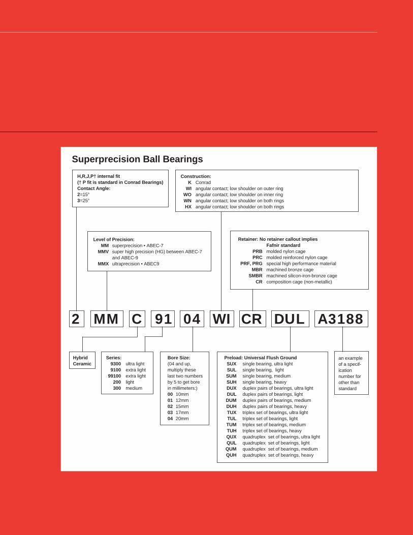
Superprecision Ball Bearings
H,R,J,P† internal fit(† P fit is standard in Conrad Bearings)Contact Angle:2=15°3=25°
HybridCeramic
Series:9300 ultra light9100 extra light
99100 extra light200 light300 medium
Bore Size:(04 and up,multiply theselast two numbersby 5 to get borein millimeters:)00 10mm01 12mm02 15mm03 17mm04 20mm
an exampleof a specif-icationnumber forother thanstandard
Preload: Universal Flush GroundSUX single bearing, ultra lightSUL single bearing, lightSUM single bearing, mediumSUH single bearing, heavyDUX duplex pairs of bearings, ultra lightDUL duplex pairs of bearings, lightDUM duplex pairs of bearings, mediumDUH duplex pairs of bearings, heavyTUX triplex set of bearings, ultra lightTUL triplex set of bearings, lightTUM triplex set of bearings, mediumTUH triplex set of bearings, heavyQUX quadruplex set of bearings, ultra lightQUL quadruplex set of bearings, lightQUM quadruplex set of bearings, mediumQUH quadruplex set of bearings, heavy
2 MM C 91 04 WI CR DUL A3188
Retainer: No retainer callout impliesFafnir standard
PRB molded nylon cagePRC molded reinforced nylon cage
PRF, PRG special high performance materialMBR machined bronze cage
SMBR machined silicon-iron-bronze cageCR composition cage (non-metallic)
Level of Precision:MM superprecision • ABEC-7
MMV super high precision (HG) between ABEC-7and ABEC-9
MMX ultraprecision • ABEC9
Construction:K Conrad
WI angular contact; low shoulder on outer ringWO angular contact; low shoulder on inner ringWN angular contact; low shoulder on both ringsHX angular contact; low shoulder on both rings

58
INTRODUCTION
MEANINGS OF PREFIXES AND SUFFIXESIn the Fafnir numbering system the basic number which denotes the sizeand series is always retained. When special variations are made as in thecase of precision bearings, prefixes and suffixes are added which havedefinite meanings as follows:
PREFIXESMM • superprecision • ABEC-7
2MM • superprecision • ABEC-7 •low contact angle-15°3MM • superprecision • ABEC-7 •high contact angle-25°
2MMV • high grade (HG) between ABEC-7 and ABEC-9 • low contactangle-15°
3MMV • high grade (HG) between ABEC-7 and ABEC-9 • high contactangle-25°
MMX • ultraprecision • ABEC-9
SUFFIXESK • deep groove radial
WI • angular contact-low shoulder on outerWO • angular contact-low shoulder on innerWN • angular contact-low shoulder on both inner and outerHX • angular contact-low shoulder on both inner and outerCR • composition cage (non-metallic)
MAR • machined aluminum cageMBR • machined bronze cageMSR • machined steel cage
SMBR • machined silicon-iron-bronze cagePRB • molded nylon cagePRC • molded nylon cage
PRF,PRG • special high performance materialDUL • flush-ground duplex bearings • light preloadDUM • flush-ground duplex bearings • medium preloadDUH • flush-ground duplex bearings • heavy preloadSUL • flush-ground single bearing • light preloadSUM • flush-ground single bearing • medium preloadSUH • flush-ground single bearing • heavy preload
SUPERPRECISION MM (ABEC-7)Superprecision bearings of the K or non-filling slot construction aregenerally used on woodworking spindles, aircraft accessory units andmachine tool applications where duplex bearings are not a definiterequirement. By virtue of the single row radial deep groove construc-tion and superprecision tolerances, they are capable of carrying thrustloads in either direction and have relatively high-speed ability.
More popular on precision machine tool spindle applications arethe WI angular-contact type bearing variations, namely 2MM-WI and3MM-WI. Since this bearing type has a low shoulder on outer ring, itcarries thrust in one direction.
SUPER HIGH PRECISION MMV (HG)Superprecision bearings are manufactured to our new HG toleranceclass, with running accuracy and performance meeting ABEC-9 (ISOP2) while maintaining noncritical features at ABEC-7 (ISO P4) level forcost-effectiveness. Bore and O.D. surfaces are coded in micron unitsfor the convenience of the discriminating machine tool builder who isstriving for optimum fitting of all spindle components.
The recent development of ceramic rolling elements in highperformance bearings offers the customer the ultimate of speedcapability, high stiffness, long life, low heat generation, and overallsystem reliability. The 99100 series is available with the option ofceramic ball selection.
ULTRAPRECISION MMX (ABEC-9)Superprecision bearings with closer tolerances and running accura-cies than ABEC-7 bearings are made to ABEC-9 tolerances. Bearingsproduced to these tolerances are generally made as WO and WNconstruction, and are use on ultra-high speed grinding spindlesdesigned for tight dimensional tolerances and super-fine surfacefinishes. Consult our Engineering Department for availability.
BEARING TYPES
ANGULAR-CONTACT BEARINGS2MM-WI types with 15° initial contact angle are designed to meet theneeds of machine builders for precision bearings which will operate atas low a temperature as possible for a wide range of speeds andoperating loads. In order for machines to produce more accurate workat a higher production rate, the bearings must provide a high degreeof rigidity in both axial and radial directions while operating a minimumtemperatures. For example, precision machining or cutting toolsimpose heavier loads on bearings than those encountered in precisiongrinding. In the former, speeds are slower and loads heavier than thelatter, where speeds are high and loads light. The 2MM-WI type givethe machine builder the flexibility required to meet such variations inapplications.
SUPERPRECISION BEARINGS
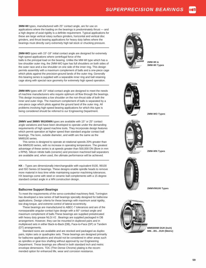
59
3MM-WI types, manufactured with 25° contact angle, are for use onapplications where the loading on the bearings is predominately thrust — anda high degree of axial rigidity is a definite requirement. Typical applications forthese are large vertical rotary surface grinders, horizontal and vertical discgrinders, and thrust bearing applications for heavy duty lathes where thebearings must directly carry extremely high tail stock or chucking pressure.
2MM-WO types with 15°-18° initial contact angle are designed for extremelyhigh-speed applications where centrifugal force of theballs is the principal load on the bearing. Unlike the MM-WI type which has alow shoulder outer ring, the 2MM-WO type has full shoulders on both sides ofthe outer race and a low shoulder on one side of the inner ring. This designpermits assembly with a maximum complement of balls and a one-piece cagewhich pilots against the precision-ground lands of the outer ring. Generallythis bearing series is supplied with a separable inner ring and ball retainingcage along with special race geometry for extremely high speed operation.
2MM-WN types with 15° initial contact angle are designed to meet the needsof machine manufacturers who require optimum oil flow through the bearings.This design incorporates a low shoulder on the non-thrust side of both theinner and outer rings. The maximum complement of balls is separated by aone-piece cage which pilots against the ground land of the outer ring. Allproblems involving high-speed bearing applications for which this type isbeing considered should be referred to our Engineering Department.
2MMV and 3MMV 99100WN types are available with 15° or 25° contactangle variations and have been developed to operate under the demandingrequirements of high speed machine tools. They incorporate design featureswhich permit operation at higher speed than standard angular contact ballbearings. The bore, outside diameter, and width are the same as theMM9100 series.
This series is designed to operate at rotational speeds 20% greater thanthe MM9100 series, with no increase in operating temperature. The greatestadvantage of these series is at speeds greater than 500,000 DN (Bore in mmx RPM). Silicon nitride balls (ceramic) and precision machined ball separatorsare available and, when used, the ultimate performance will be achieved.
HX – Types are dimensionally interchangeable with equivalent 9100, 99100and ISO Series-10 bearings. These designs enable spindle heads to removemore material in less time while maintaining superior machining tolerances.HX bearings come with steel or ceramic ball complements with a 15 degreestandard contact angle in a WN construction design.
Ballscrew Support BearingsTo meet the requirements of the servo-controlled machinery field, Torringtonhas developed a new series of ball bearings specially designed for ballscrewapplications. Design criteria for these bearings with maximum axial rigidity,low drag torque, and extreme control of lateral eccentricity.
These bearings are manufactured to ABEC-7 tolerances and are of thenonseparable angular-contact type design with a 60° contact angle andmaximum complement of balls.These bearings are supplied prelubricatedwith heavy duty grease NLGI #2 . Bearings are supplied packaged in DBarrangement. However, they can be mounted in duplexed pairs and inmultiplexed sets in either Back-to-Back (DB), Face-to-Face (DF) or Tandem(DT) arrangements.
Standard sizes are available and are stocked and packaged as duplexpairs, triplex sets or quadruplex sets. These bearings are designed primarilyfor ballscrew applications and should not be considered in other areas suchas spindles or gear-box shafting without approval by our EngineeringDepartment. These bearings are offered in both standard inch and metricenvelope dimensions. TDC (Thin Dense Chrome) plating is the recom-mended option for enhanced life, wear and corrosion resistance.
2MM-WI &3MM-WI Types
2MM-WO Types
2MM-WN Types
2MMV99100 Types
MM9300WI DUH (Inch)MM…BS…DUH (Metric)
SUPERPRECISION BEARINGS

60
DIMENSIONS – TOLERANCESBearing Bore Inner Outside Diameter Outer Width
(2)Fillet Wt. Load Ratings
Number d Ring D Ring C Radius(1)
Static Extendedtolerance tolerance +0.000" Load Dynamic+0.0000" +0.0000" -.005" Rating Load
+0.000 mm +0.000 mm +0.00 mm CO Ratingto minus eccen. to minus eccen. -.13 mm CE
ContactAngle15° in. mm in. mm in. mm in. mm in. mm in. mm in. mm in. mm lbs. kg lbs. N lbs. N
2MM9300WI-CR 0.3937 10 0.00015 0.0038 0.0001 0.0025 0.8661 22 0.0002 0.005 0.0002 0.0051 0.2362 6 0.012 0.3 0.02 0.009 250 1100 670 30002MM9301WI-CR 0.4724 12 0.00015 0.0038 0.0001 0.0025 0.9449 24 0.0002 0.005 0.0002 0.0051 0.2362 6 0.012 0.3 0.03 0.014 290 1290 780 34502MM9302WI-CR 0.5906 15 0.00015 0.0038 0.0001 0.0025 1.1024 28 0.0002 0.005 0.0002 0.0051 0.2756 7 0.012 0.3 0.04 0.018 360 1600 865 39002MM9303WI-CR 0.6693 17 0.00015 0.0038 0.0001 0.0025 1.1811 30 0.0002 0.005 0.0002 0.0051 0.2756 7 0.012 0.3 0.04 0.018 425 1860 950 42502MM9304WI-CR 0.7874 20 0.00015 0.0038 0.00015 0.0038 1.4567 37 0.0002 0.005 0.0002 0.0051 0.3543 9 0.012 0.3 0.08 0.036 680 3050 1530 6800
2MM9305WI-CR 0.9843 25 0.00015 0.0038 0.00015 0.0038 1.6535 42 0.0002 0.005 0.0002 0.0051 0.3543 9 0.012 0.3 0.1 0.045 865 3800 1730 76502MM9306WI-CR 1.1811 30 0.00015 0.0038 0.00015 0.0038 1.8504 47 0.0002 0.005 0.0002 0.0051 0.3543 9 0.012 0.3 0.11 0.05 1000 4400 1800 80002MM9307WI-CR 1.3780 35 0.0002 0.0051 0.00015 0.0038 2.1654 55 0.0002 0.005 0.0002 0.0051 0.3937 10 0.024 0.6 0.17 0.077 1340 6000 2400 106002MM9308WI-CR 1.5748 40 0.0002 0.0051 0.00015 0.0038 2.4409 62 0.0002 0.005 0.0002 0.0051 0.4724 12 0.024 0.6 0.25 0.113 1760 7800 3050 134002MM9309WI-CR 1.7717 45 0.0002 0.0051 0.00015 0.0038 2.6772 68 0.0002 0.005 0.0002 0.0051 0.4724 12 0.024 0.6 0.28 0.127 2000 8800 3200 14300
2MM9310WI-CR 1.9685 50 0.0002 0.0051 0.00015 0.0038 2.8346 72 0.0002 0.005 0.0002 0.0051 0.4724 12 0.024 0.6 0.3 0.136 2200 9800 3350 150002MM9311WI-CR 2.1654 55 0.0002 0.0051 0.00015 0.0038 3.1496 80 0.0002 0.005 0.0002 0.0051 0.5118 13 0.039 1.0 0.41 0.186 2750 12200 4150 183002MM9312WI-CR 2.3622 60 0.0002 0.0051 0.00015 0.0038 3.3465 85 0.0003 0.008 0.0002 0.0051 0.5118 13 0.039 1.0 0.43 0.195 3050 13420 4300 193002MM9313WI-CR 2.5591 65 0.0002 0.0051 0.00015 0.0038 3.5433 90 0.0003 0.008 0.0002 0.0051 0.5118 13 0.039 1.0 0.47 0.213 3350 14600 4500 200002MM9314WI-CR 2.7559 70 0.0002 0.0051 0.00015 0.0038 3.9370 100 0.0003 0.008 0.0002 0.0051 0.6299 16 0.039 1.0 0.75 0.34 4300 19300 6100 27000
2MM9315WI-CR 2.9528 75 0.0002 0.0051 0.00015 0.0038 4.1339 105 0.0003 0.008 0.0002 0.0051 0.6299 16 0.039 1.0 0.8 0.363 4550 20400 6200 275002MM9316WI-CR 3.1496 80 0.0002 0.0051 0.00015 0.0038 4.3307 110 0.0003 0.008 0.0002 0.0051 0.6299 16 0.039 1.0 0.84 0.381 5000 22000 6400 285002MM9317WI-CR 3.3465 85 0.00025 0.0064 0.0002 0.0051 4.7244 120 0.0003 0.008 0.0002 0.0051 0.7087 18 0.039 1.0 1.21 0.549 5700 25000 7350 325002MM9318WI-CR 3.5433 90 0.00025 0.0064 0.0002 0.0051 4.9213 125 0.0004 0.010 0.0002 0.0051 0.7087 18 0.039 1.0 1.26 0.572 6700 29000 8500 380002MM9319WI-CR 3.7402 95 0.00025 0.0064 0.0002 0.0051 5.1181 130 0.0004 0.010 0.0003 0.0076 0.7087 18 0.039 1.0 1.33 0.604 7200 32000 8800 39000
2MM9320WI-CR 3.9370 100 0.00025 0.0064 0.0002 0.0051 5.5118 140 0.0004 0.010 0.0003 0.0076 0.7874 20 0.039 1.0 1.87 0.849 7500 33500 9000 400002MM9322WI-CR 4.3307 110 0.00025 0.0064 0.0002 0.0051 5.9055 150 0.0004 0.010 0.0003 0.0076 0.7874 20 0.039 1.0 2.02 0.917 8150 36000 9150 405002MM9324WI-CR 4.7244 120 0.00025 0.0064 0.0002 0.0051 6.4961 165 0.0004 0.010 0.0003 0.0076 0.8661 22 0.039 1.0 2.74 1.244 10400 46500 11800 520002MM9326WI-CR 5.1181 130 0.0003 0.0076 0.0003 0.0076 7.0866 180 0.0004 0.010 0.0003 0.0076 0.9449 24 0.059 1.5 3.62 1.643 13200 58500 15000 655002MM9328WI-CR 5.5118 140 0.0003 0.0076 0.0003 0.0076 7.4803 190 0.0004 0.010 0.0004 0.0120 0.9449 24 0.059 1.5 3.87 1.757 14300 63000 15300 68000
2MM9330WI-CR 5.9055 150 0.0003 0.0076 0.0003 0.0076 8.2677 210 0.0004 0.010 0.0004 0.0120 1.1024 28 0.079 2.0 5.89 2.674 21200 95000 23600 1060002MM9334WI-CR 6.6929 170 0.0003 0.0076 0.0003 0.0076 9.0551 230 0.0004 0.010 0.0004 0.0120 1.1024 28 0.079 2.0 6.38 2.896 23200 104000 25500 112000
(1) Maximum shaft or housing fillet radius which bearing corners clear.
(2 )See “Width Tolerances” page E63 for width tolerance of multiplex sets. One piece outer ring-piloted composition cage is standard.
Ultra Light2MM9300WI Series
2MM9300WI Series
Dd
C
C
SUPERPRECISION BEARINGS

61
Bearing Bore Outside Diameter Width Fillet Wt. Load Ratings
Number d D C Radius(1)
Static Extendedtolerance tolerance Load Dynamic+0.0000" +0.0000" Rating Load
+0.000 mm 0.000 mm +0.000",-.005" CO Ratingto minus to minus +0.00 mm,-.13mm CE
in. mm in. mm in. mm in. mm in. mm in. mm lbs. kg lbs. N lbs. N
MM9101K-CR 0.4724 12 0.00015 0.0038 1.1024 28 0.0002 0.005 0.315 8 0.012 0.3 0.05 0.023 465 2080 1270 5700MM9103K-CR 0.6693 17 0.00015 0.0038 1.3780 35 0.0002 0.005 0.3937 10 0.012 0.3 0.1 0.045 630 2800 1500 6700MM9104K-CR 0.7874 20 0.00015 0.0038 1.6535 42 0.0002 0.005 0.4724 12 0.024 0.6 0.16 0.073 865 3900 2160 9650
MM9105K-CR 0.9843 25 0.00015 0.0038 1.8504 47 0.0002 0.005 0.4724 12 0.024 0.6 0.18 0.082 1140 5100 2500 11200MM9106K-CR 1.1811 30 0.00015 0.0038 2.1654 55 0.0002 0.005 0.5118 13 0.039 1.0 0.26 0.118 1600 7200 3350 14600MM9107K-CR 1.3780 35 0.0002 0.0051 2.4409 62 0.0002 0.005 0.5512 14 0.039 1.0 0.35 0.159 2000 9000 4000 17600MM9108K-CR 1.5748 40 0.0002 0.0051 2.6772 68 0.0002 0.005 0.5906 15 0.039 1.0 0.43 0.195 2240 10000 4150 18600MM9109K-CR 1.7717 45 0.0002 0.0051 2.9528 75 0.0002 0.005 0.6299 16 0.039 1.0 0.55 0.249 2900 13200 5200 23200
MM9110K-CR 1.9685 50 0.0002 0.0051 3.1496 80 0.0002 0.005 0.6299 16 0.039 1.0 0.6 0.272 3250 14300 5400 24000MM9111K-CR 2.1654 55 0.0002 0.0051 3.5433 90 0.0003 0.008 0.7087 18 0.039 1.0 0.86 0.39 4150 18300 7100 31500
MM9115K-CR 2.9528 75 0.0002 0.0051 4.5276 115 0.0003 0.008 0.7874 20 0.039 1.0 1.5 0.68 6550 29000 9800 44000MM9116K-CR 3.1496 80 0.0002 0.0051 4.4913 125 0.0004 0.010 0.8661 22 0.039 1.0 1.95 0.885 7800 34500 11800 53000MM9117K-CR 3.3465 85 0.00025 0.0064 5.1181 130 0.0004 0.010 0.8661 22 0.039 1.0 2.13 0.966 8300 37500 12500 55000MM9118K-CR 3.5433 90 0.00025 0.0064 5.5118 140 0.0004 0.010 0.9449 24 0.059 1.5 2.55 1.157 9650 43000 14600 64000MM9120K-CR 3.9370 100 0.00025 0.0064 5.9055 150 0.0004 0.010 0.9449 24 0.059 1.5 2.9 1.315 10600 46900 15600 67000
MM9122K-CR 4.3307 110 0.00025 0.0064 6.6929 170 0.0004 0.010 1.1024 28 0.079 2.0 4.4 1.996 13200 58500 18600 83000MM9124K-CR 4.7244 120 0.00025 0.0064 7.0866 180 0.0004 0.010 1.1024 28 0.079 2.0 4.85 2.2 14300 63000 19300 86500MM9126K-CR 5.1181 130 0.0003 0.0076 7.8740 200 0.0004 0.010 1.2992 33 0.079 2.0 7.35 3.334 18300 81500 25500 112000
(1) Maximum shaft or housing fillet radius which bearing corners clear.Two piece inner ring-piloted composition cage is standard.
Extra LightMM9100K Series
D
C
d
MM9100K
SUPERPRECISION BEARINGS

62
TO ORDER: Specify prefix 2MM for 15 ° contact angle. Example: 2MM9103WI Specify prefix 3MM for 25 ° contact angle. Example: 3MM9103WI
Bearing Number Bore Outside Diameter Width (2) Fillet Wt Load Ratings
d D C Radius(1)
2MM9100WI Series 3MM9100WI Series
Static Extended Static Extendedtolerance tolerance Load Dynamic Load Dynamic
Contact Contact +0.0000" +0.0000" Rating Load Rating LoadAngle Angle +0.000 mm +0.000 mm +0.000",-0.005" CO Rating C O Rating
25° 15° to minus to minus +0.00mm-.13mm CE CE
in. mm in. mm in. mm in. mm in. mm in. mm lbs. kg lbs. N lbs. N lbs. N lbs. N
(3MM) 2MM9100WI 0.3937 10 0.00015 0.0038 1.0236 26 0.0002 0.005 0.3150 8 0.012 0.3 0.04 0.018 430 1900 1220 5500 415 1830 1180 5300(3MM) 2MM9101WI 0.4724 12 0.00015 0.0038 1.1024 28 0.0002 0.005 0.3150 8 0.012 0.3 0.05 0.023 570 2550 1460 6400 550 2400 1400 6200(3MM) 2MM9102WI-CR 0.5906 15 0.00015 0.0038 1.2598 32 0.0002 0.005 0.3543 9 0.012 0.3 0.08 0.036 655 2900 1560 6950 630 2800 1500 6550(3MM) 2MM9103WI-CR 0.6693 17 0.00015 0.0038 1.3780 35 0.0002 0.005 0.3937 10 0.012 0.3 0.1 0.045 680 3000 1560 6950 640 2850 1500 6550
(3MM) 2MM9104WI 0.7874 20 0.00015 0.0038 1.6535 42 0.0002 0.005 0.4724 12 0.024 0.6 0.16 0.073 1160 5200 2600 11600 1120 4900 2500 11000(3MM) 2MM9105WI 0.9843 25 0.00015 0.0038 1.8504 47 0.0002 0.005 0.4724 12 0.024 0.6 0.18 0.082 1430 6400 2900 12900 1370 6100 2800 12200(3MM) 2MM9106WI 1.1811 30 0.00015 0.0038 2.1654 55 0.0002 0.005 0.5118 13 0.039 1.0 0.26 0.118 2000 8800 3750 16600 1900 8500 3600 16000(3MM) 2MM9107WI 1.3780 35 0.0002 0.0051 2.4409 62 0.0002 0.005 0.5512 14 0.039 1.0 0.35 0.159 2650 11800 4750 21200 2500 11200 4550 20000(3MM) 2MM9108WI 1.5748 40 0.0002 0.0051 2.6772 68 0.0002 0.005 0.5906 15 0.039 1.0 0.43 0.195 2900 12900 4900 22000 2750 12200 4650 20800
(3MM) 2MM9109WI 1.7717 45 0.0002 0.0051 2.9528 75 0.0002 0.005 0.6299 16 0.039 1.0 0.55 0.249 3750 16600 6100 27000 3550 16000 5700 25500(3MM) 2MM9110WI 1.9685 50 0.0002 0.0051 3.1496 80 0.0002 0.005 0.6299 16 0.039 1.0 0.6 0.272 4050 18000 6300 28000 3800 17000 5850 26500(3MM) 2MM9111WI 2.1654 55 0.0002 0.0051 3.5433 90 0.0003 0.008 0.7087 18 0.039 1.0 0.86 0.39 5600 25000 8500 38000 5300 23600 8000 36000(3MM) 2MM9112WI 2.3622 60 0.0002 0.0051 3.7402 95 0.0003 0.008 0.7087 18 0.039 1.0 0.92 0.417 6000 26500 8800 39000 5700 25000 8300 36500(3MM) 2MM9113WI 2.5591 65 0.0002 0.0051 3.9370 100 0.0003 0.008 0.7087 18 0.039 1.0 0.98 0.445 6300 28000 9000 40000 6000 27000 8500 37500
(3MM) 2MM9114WI 2.7559 70 0.0002 0.0051 4.3307 110 0.0003 0.008 0.7874 20 0.039 1.0 1.39 0.631 8000 35500 11400 50000 7500 33500 10800 48000(3MM) 2MM9115WI 2.9528 75 0.0002 0.0051 4.5276 115 0.0003 0.008 0.7874 20 0.039 1.0 1.5 0.68 8500 37500 11600 52000 8000 35500 11000 49000(3MM) 2MM9116WI 3.1496 80 0.0002 0.0051 4.9213 125 0.00035 0.009 0.8661 22 0.039 1.0 1.95 0.885 10800 48000 14600 65500 10200 45500 13700 62000(3MM) 2MM9117WI 3.3465 85 0.00025 0.0065 5.1181 130 0.00035 0.009 0.8661 22 0.039 1.0 2.13 0.996 11400 51000 15000 67000 10800 48000 14000 63000(3MM) 2MM9118WI 3.5433 90 0.00025 0.0065 5.5118 140 0.00035 0.009 0.9449 24 0.059 1.5 2.55 1.157 13400 60000 18000 80000 12700 57000 17000 75000
(3MM) 2MM9120WI 3.9370 100 0.00025 0.0065 5.9055 150 0.00035 0.009 0.9449 24 0.059 1.5 2.9 1.315 15000 67000 18600 83000 14300 63000 17600 80000(3MM) 2MM9121WI-CR 4.1339 105 0.00025 0.0065 6.2992 160 0.0004 0.010 1.0236 26 0.079 2.0 3.22 1.461 17300 78000 22000 98000 16600 73500 20800 93000(3MM) 2MM9122WI-CR 4.3307 110 0.00025 0.0065 6.6929 170 0.0004 0.010 1.1024 28 0.079 2.0 4.4 1.996 20000 90000 24500 110000 19000 85000 23200 104000(3MM) 2MM9124WI 4.7244 120 0.00025 0.0065 7.0866 180 0.0004 0.010 1.1024 28 0.079 2.0 4.85 2.2 21200 95000 25000 112000 20000 90000 23600 106000(3MM) 2MM9126WI 5.1181 130 0.0003 0.0076 7.8740 200 0.0004 0.010 1.2992 33 0.079 2.0 7.39 3.352 26500 118000 32000 143000 25500 112000 30500 134000
(3MM) 2MM9128WI-CR 5.5118 140 0.0003 0.0076 8.2677 210 0.0004 0.010 1.2992 33 0.079 2.0 7.9 3.583 28000 125000 32500 146000 26500 118000 31000 140000(3MM) 2MM9130WI-CR 5.9055 150 0.0003 0.0076 8.8583 225 0.0004 0.010 1.3780 35 0.079 2.0 8.6 3.901 32500 146000 37500 166000 31000 137000 35500 160000(3MM) 2MM9132WI-CR 6.2992 160 0.0003 0.0076 9.4488 240 0.0004 0.010 1.4961 38 0.079 2.0 10.7 4.854 37500 166000 42500 190000 36000 160000 40500 180000(3MM) 2MM9134WI-CR 6.6929 170 0.0003 0.0076 10.2362 260 0.0004 0.010 1.6535 42 0.079 2.0 15.5 7.031 47500 212000 53000 236000 45000 200000 50000 220000(3MM) 2MM9140WI-CR 7.8740 200 0.0004 0.0102 12.2047 310 0.0005 0.013 2.0079 51 0.079 2.0 25 11.34 65500 290000 67000 300000 62000 275000 63000 280000(1)
Maximum shaft or housing fillet radius which bearing corners clear.(2)
See “width tolerance” page E63 for width tolerance of multiple sets.
One piece molded nylon, glass fiber reinforced outer ring- piloted cage is standardexcept where designated CR which is an outer ring-piloted composition cage.
Extra Light2MM9100WI and3MM9100WI Series
Dd
C2MM9100WI and
3MM9100WI Series
SUPERPRECISION BEARINGS
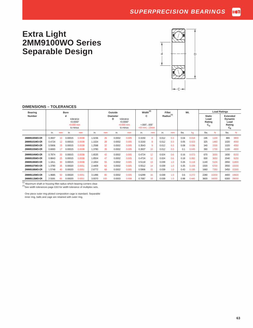
63
Extra Light2MM9100WO SeriesSeparable Design Dd
C
DIMENSIONS – TOLERANCESBearing Bore Outside Width
(2)Fillet Wt. Load Ratings
Number d Diameter C Radius(1)
Static Extendedtolerance D tolerance Load Dynamic+0.0000" +0.0000" Rating Load
+0.000 mm +0.000 mm +.000",-.005" CO Ratingto minus to minus +00 mm,-.13mm CE
in. mm in. mm in. mm in. mm in. mm in. mm lbs. kg lbs. N lbs. N
2MM9100WO-CR 0.3937 10 0.00015 0.0038 1.0236 26 0.0002 0.005 0.3150 8 0.012 0.3 0.04 0.018 245 1100 865 38002MM9101WO-CR 0.4724 12 0.00015 0.0038 1.1024 28 0.0002 0.005 0.3150 8 0.012 0.3 0.05 0.023 325 1460 1020 45502MM9102WO-CR 0.5906 15 0.00015 0.0038 1.2598 32 0.0002 0.005 0.3543 9 0.012 0.3 0.08 0.036 340 1530 1020 45502MM9103WO-CR 0.6693 17 0.00015 0.0038 1.3780 35 0.0002 0.005 0.3937 10 0.012 0.3 0.1 0.045 390 1730 1100 4900
2MM9104WO-CR 0.7874 20 0.00015 0.0038 1.6535 42 0.0002 0.005 0.4724 12 0.024 0.6 0.16 0.073 670 3000 1830 81502MM9105WO-CR 0.9843 25 0.00015 0.0038 1.8504 47 0.0002 0.005 0.4724 12 0.024 0.6 0.18 0.082 830 3650 2040 91502MM9106WO-CR 1.1811 30 0.00015 0.0038 2.1654 55 0.0002 0.005 0.5118 13 0.039 1.0 0.26 0.118 1140 5100 2650 118002MM9107WO-CR 1.3780 35 0.00020 0.0051 2.4409 62 0.0002 0.005 0.5512 14 0.039 1.0 0.35 0.159 1500 6700 3550 150002MM9108WO-CR 1.5748 40 0.00020 0.0051 2.6772 68 0.0002 0.005 0.5906 15 0.039 1.0 0.43 0.195 1660 7350 3450 15300
2MM9110WO-CR 1.9685 50 0.00020 0.0051 3.1496 80 0.0002 0.005 0.6299 16 0.039 1.0 0.6 0.272 2280 10200 4400 196002MM9113WO-CR 2.5591 65 0.00020 0.0051 3.9370 100 0.0003 0.008 0.7087 18 0.039 1.0 0.98 0.445 3600 16000 6300 28000
(1) Maximum shaft or housing fillet radius which bearing corners clear.
(2)See width tolerances page E63 for width tolerance of multiplex sets.
One piece outer ring piloted composition cage is standard. Separableinner ring, balls and cage are retained with outer ring.
SUPERPRECISION BEARINGS
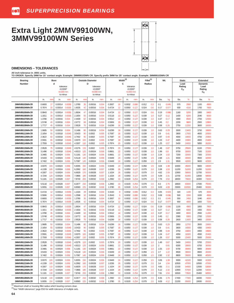
64
Dd
C
Extra Light 2MMV99100WN,3MMV99100WN Series
DIMENSIONS – TOLERANCESAll inch tolerance in .0001 units.TO ORDER: Specify 2MM for 15 ° contact angle. Example: 2MM99103WN CR. Specify prefix 3MM for 25 ° contact angle. Example: 3MM99103WN CR
Bearing Bore Outside Diameter Width(2)
Fillet(1)
Wt. Static ExtendedNumber d D C Radius Load Dynamic
tolerance tolerance tolerance Rating Load+0.0000" +0.0000" +0.0000" CO Rating
+0.000 mm +0.000 mm +0.000 mm CEto minus to minus to minus
in. mm in. mm in. mm in. mm in. mm in. mm in. mm lbs. kg lbs. N lbs. N
2MMV99103WN-CR 0.6693 17 0.00014 0.0035 1.3780 35 0.00016 0.004 0.3937 10 0.0032 0.080 0.012 0.3 0.1 0.045 570 2550 1100 49002MMV99104WN-CR 0.7874 20 0.00014 0.0035 1.6535 42 0.00016 0.004 0.4724 12 0.0050 0.127 0.024 0.6 0.17 0.077 930 4150 1700 7600
2MMV99105WN-CR 0.9843 25 0.00014 0.0035 1.8504 47 0.00016 0.004 0.4724 12 0.0050 0.127 0.024 0.6 0.19 0.086 1160 5200 1900 84002MMV99106WN-CR 1.1811 30 0.00014 0.0035 2.1654 55 0.00016 0.004 0.5118 13 0.0050 0.127 0.039 1.0 0.27 0.12 1400 6200 2040 90002MMV99107WN-CR 1.3780 35 0.00016 0.004 2.4409 62 0.00016 0.004 0.5512 14 0.0050 0.127 0.039 1.0 0.37 0.17 1900 8500 2700 120002MMV99108WN-CR 1.5748 40 0.00016 0.004 2.6772 68 0.00016 0.004 0.5906 15 0.0050 0.127 0.039 1.0 0.45 0.2 2200 9800 2900 128002MMV99109WN-CR 1.7717 45 0.00016 0.004 2.9528 75 0.00016 0.004 0.6299 16 0.0050 0.127 0.039 1.0 0.58 0.26 2750 12200 3600 16000
2MMV99110WN-CR 1.9685 50 0.00016 0.004 3.1496 80 0.00016 0.004 0.6299 16 0.0050 0.127 0.039 1.0 0.63 0.29 3000 13400 3750 166002MMV99111WN-CR 2.1654 55 0.00018 0.0045 3.5433 90 0.0002 0.005 0.7087 18 0.0050 0.127 0.039 1.0 0.9 0.41 3800 17000 4600 205002MMV99112WN-CR 2.3622 60 0.00018 0.0045 3.7402 95 0.0002 0.005 0.7087 18 0.0050 0.127 0.039 1.0 0.97 0.44 4000 18000 4700 208002MMV99113WN-CR 2.5591 65 0.00018 0.0045 3.9370 100 0.0002 0.005 0.7087 18 0.0050 0.127 0.039 1.0 1.03 0.47 4400 19300 4900 216002MMV99114WN-CR 2.7559 70 0.00018 0.0045 4.3307 110 0.0002 0.005 0.7874 20 0.0050 0.127 0.039 1.0 1.25 0.57 5400 24000 5850 26200
2MMV99115WN-CR 2.9528 75 0.00018 0.0045 4.5276 115 0.0002 0.005 0.7874 20 0.0050 0.127 0.039 1.0 1.48 0.67 5750 25500 6100 270002MMV99116WN-CR 3.1496 80 0.00018 0.0045 4.9213 125 0.00024 0.006 0.8661 22 0.0050 0.127 0.039 1.0 1.99 0.9 6700 30000 7100 315002MMV99117WN-CR 3.3465 85 0.00024 0.006 5.1181 130 0.00024 0.006 0.8661 22 0.0050 0.127 0.039 1.0 2.24 1.02 7200 32000 7300 325002MMV99118WN-CR 3.5433 90 0.00024 0.006 5.5118 140 0.00024 0.006 0.9449 24 0.0050 0.127 0.059 1.5 2.68 1.21 9000 40000 9500 420002MMV99119WN-CR 3.7402 95 0.00024 0.006 5.7087 145 0.00024 0.006 0.9449 24 0.0050 0.127 0.059 1.5 2.9 1.31 9500 42000 9600 42500
2MMV99120WN-CR 3.9370 100 0.00024 0.006 5.9055 150 0.00024 0.006 0.9449 24 0.0050 0.127 0.059 1.5 3.04 1.38 10000 45000 9900 440002MMV99121WN-CR 4.1339 105 0.00024 0.006 6.2992 160 0.00028 0.007 1.0236 26 0.0050 0.127 0.079 2.0 3.38 1.53 11200 51000 11200 510002MMV99122WN-CR 4.3307 110 0.00024 0.006 6.6929 170 0.00028 0.007 1.1024 28 0.0050 0.127 0.079 2.0 4.62 2.09 12900 58000 12700 565002MMV99124WN-CR 4.7244 120 0.00024 0.006 7.0866 180 0.00028 0.007 1.1024 28 0.0050 0.127 0.079 2.0 5.09 2.31 13700 61000 13000 580002MMV99126WN-CR 5.1181 130 0.00028 0.007 7.8740 200 0.00032 0.008 1.2992 33 0.0100 0.254 0.079 2.0 7.76 3.52 18000 79000 16300 73000
2MMV99128WN-CR 5.5118 140 0.00028 0.007 8.2677 210 0.00032 0.008 1.2992 33 0.0100 0.254 0.079 2.0 8.3 3.76 18600 83000 17000 750002MMV99130WN-CR 5.9055 150 0.00028 0.007 8.8583 225 0.00032 0.008 1.3780 35 0.0100 0.254 0.079 2.0 9.03 4.09 23000 102000 20400 90000
3MMV99101WN-CR 0.4724 12 0.00014 0.0035 1.1024 28 0.00016 0.004 0.3150 8 0.0032 0.080 0.012 0.3 0.05 0.023 320 1430 670 30003MMV99102WN-CR 0.5906 15 0.00014 0.0035 1.2598 32 0.00016 0.004 0.3543 9 0.0032 0.080 0.012 0.3 0.08 0.036 500 2200 1020 45003MMV99103WN-CR 0.6693 17 0.00014 0.0035 1.3780 35 0.00016 0.004 0.3937 10 0.0032 0.080 0.012 0.3 0.1 0.045 550 2450 1040 46503MMV99104WN-CR 0.7874 20 0.00014 0.0035 1.6535 42 0.00016 0.004 0.4724 12 0.0050 0.127 0.024 0.6 0.17 0.077 900 4000 1600 7200
3MMV99105WN-CR 0.9843 25 0.00014 0.0035 1.8504 47 0.00016 0.004 0.4724 12 0.0050 0.127 0.024 0.6 0.19 0.086 1100 4900 1800 78003MMV99106WN-CR 1.1811 30 0.00014 0.0035 2.1654 55 0.00016 0.004 0.5118 13 0.0050 0.127 0.039 1.0 0.27 0.12 1320 6000 1900 85003MMV99107WN-CR 1.3780 35 0.00016 0.004 2.4409 62 0.00016 0.004 0.5512 14 0.0050 0.127 0.039 1.0 0.37 0.17 1800 8000 2550 112003MMV99108WN-CR 1.5748 40 0.00016 0.004 2.6772 68 0.00016 0.004 0.5906 15 0.0050 0.127 0.039 1.0 0.45 0.2 2080 9300 2700 120003MMV99109WN-CR 1.7717 45 0.00016 0.004 2.9528 75 0.00016 0.004 0.6299 16 0.0050 0.127 0.039 1.0 0.58 0.26 2600 11600 3400 15000
3MMV99110WN-CR 1.9685 50 0.00016 0.004 3.1496 80 0.00016 0.004 0.6299 16 0.0050 0.127 0.039 1.0 0.63 0.29 2850 12700 3500 156003MMV99111WN-CR 2.1654 55 0.00018 0.0045 3.5433 90 0.0002 0.005 0.7087 18 0.0050 0.127 0.039 1.0 0.9 0.41 3600 16000 4350 194003MMV99112WN-CR 2.3622 60 0.00018 0.0045 3.7402 95 0.0002 0.005 0.7087 18 0.0050 0.127 0.039 1.0 0.98 0.44 3750 16800 4400 196003MMV99113WN-CR 2.5591 65 0.00018 0.0045 3.9370 100 0.0002 0.005 0.7087 18 0.0050 0.127 0.039 1.0 1.04 0.47 4050 18300 4550 204003MMV99114WN-CR 2.7559 70 0.00018 0.0045 4.3307 110 0.0002 0.005 0.7874 20 0.0050 0.127 0.039 1.0 1.26 0.57 5000 22400 5500 25000
3MMV99115WN-CR 2.9528 75 0.00018 0.0045 4.5276 115 0.0002 0.005 0.7874 20 0.0050 0.127 0.039 1.0 1.49 0.67 5400 24000 5700 255003MMV99116WN-CR 3.1496 80 0.00018 0.0045 4.9213 125 0.00024 0.006 0.8661 22 0.0050 0.127 0.039 1.0 2 0.91 6300 28000 6700 300003MMV99117WN-CR 3.3465 85 0.00024 0.006 5.1181 130 0.00024 0.006 0.8661 22 0.0050 0.127 0.039 1.0 2.25 1.02 6700 30000 6900 305003MMV99118WN-CR 3.5433 90 0.00024 0.006 5.5118 140 0.00024 0.006 0.9449 24 0.0050 0.127 0.059 1.5 2.7 1.22 8500 38000 8900 400003MMV99119WN-CR 3.7402 95 0.00024 0.006 5.7087 145 0.00024 0.006 0.9449 24 0.0050 0.127 0.059 1.5 2.92 1.32 8800 39000 9000 40500
3MMV99120WN-CR 3.9370 100 0.00024 0.006 5.9055 150 0.00024 0.006 0.9449 24 0.0050 0.127 0.059 1.5 3.06 1.39 9300 41500 9300 415003MMV99121WN-CR 4.1339 105 0.00024 0.006 6.2992 160 0.00028 0.007 1.0236 26 0.0050 0.127 0.079 2.0 3.4 1.54 10500 47000 10500 470003MMV99122WN-CR 4.3307 110 0.00024 0.006 6.6929 170 0.00028 0.007 1.1024 28 0.0050 0.127 0.079 2.0 4.65 2.11 12100 54000 12000 530003MMV99124WN-CR 4.7244 120 0.00024 0.006 7.0866 180 0.00028 0.007 1.1024 28 0.0050 0.127 0.079 2.0 5.12 2.32 12900 57000 12200 540003MMV99126WN-CR 5.1181 130 0.00028 0.007 7.8740 200 0.00032 0.008 1.2992 33 0.0100 0.254 0.079 2.0 7.81 3.54 16500 73500 15400 68500
3MMV99128WN-CR 5.5118 140 0.00028 0.007 8.2677 210 0.00032 0.008 1.2992 33 0.0100 0.254 0.079 2.0 8.35 3.79 17400 77000 16000 700003MMV99130WN-CR 5.9055 150 0.00028 0.007 8.8583 225 0.00032 0.008 1.3780 35 0.0100 0.254 0.079 2.0 9.09 4.12 21200 95000 19000 85000
(1) Maximum shaft or housing fillet radius which bearing corners clear.
(2)See ”Width tolerances” page E63 for width tolerance of multiple sets.
SUPERPRECISION BEARINGS

65
Light MM200K Series
DIMENSIONS – TOLERANCESBearing Bore Outside Diameter Width Fillet Wt. Load Ratings
Number d D C Radius(1)
Static Extendedtolerance tolerance Load Dynamic+0.0000" +0.0000" Rating Load
+0.000 mm +0.000 mm +0.000",-0.005" CO Ratingto minus to minus +0.00 mm,-.13 mm CE
in. mm in. mm in. mm in. mm in. mm in. mm lbs. kg lbs. N lbs. N
MM201K-CR 0.4724 12 0.00015 0.0038 1.2598 32 0.0002 0.005 0.3937 10 0.024 0.6 0.1 0.045 600 2650 1700 7500MM202K-CR 0.5906 15 0.00015 0.0038 1.3780 35 0.0002 0.005 0.4331 11 0.024 0.6 0.12 0.054 720 3200 1900 8500MM203K-CR 0.6693 17 0.00015 0.0038 1.5748 40 0.0002 0.005 0.4724 12 0.024 0.6 0.15 0.068 930 4150 2400 10600MM204K-CR 0.7874 20 0.00015 0.0038 1.8504 47 0.0002 0.005 0.5512 14 0.039 1.0 0.25 0.113 1290 5700 3200 14300MM205K-CR 0.9843 25 0.00015 0.0038 2.0472 52 0.0002 0.005 0.5906 15 0.039 1.0 0.3 0.136 1500 6800 3450 15600
MM206K-CR 1.1811 30 0.00015 0.0038 2.4409 62 0.0002 0.005 0.6299 16 0.039 1.0 0.5 0.227 2200 9800 4900 21600MM207K-CR 1.3780 35 0.00020 0.0051 2.8346 72 0.0002 0.005 0.6693 17 0.039 1.0 0.7 0.318 3000 13200 6400 28500MM208K-CR 1.5748 40 0.00020 0.0051 3.1496 80 0.0003 0.008 0.7087 18 0.039 1.0 0.9 0.408 3900 17300 8150 36000MM209K-CR 1.7717 45 0.00020 0.0051 3.3465 85 0.0003 0.008 0.7480 19 0.039 1.0 0.96 0.435 4000 17600 8150 36000MM210K-CR 1.9685 50 0.00020 0.0051 3.5433 90 0.0003 0.008 0.7847 20 0.039 1.0 1.05 0.476 4500 20000 8800 39000
MM211K-CR 2.1654 55 0.00020 0.0051 3.9370 100 0.0003 0.008 0.8268 21 0.059 1.5 1.5 0.68 5700 25500 10800 48000MM212K-CR 2.3622 60 0.00020 0.0051 4.3307 110 0.0003 0.008 0.8661 22 0.059 1.5 1.9 0.862 6300 28000 12200 54000MM213K-CR 2.5591 65 0.00020 0.0051 4.7244 120 0.0003 0.008 0.9055 23 0.059 1.5 2.35 1.066 7800 34500 14300 64000MM214K-CR 2.7559 70 0.00020 0.0051 4.9213 125 0.0004 0.010 0.9449 24 0.059 1.5 2.5 1.134 8500 37750 15600 69500MM215K-CR 2.9528 75 0.00020 0.0051 5.1181 130 0.0004 0.010 0.9843 25 0.059 1.5 2.7 1.225 8650 38000 15600 69500
MM216K-CR 3.1496 80 0.00020 0.0051 5.5118 140 0.0004 0.010 1.0236 26 0.079 2.0 3.1 1.406 10200 45500 18000 80000
(1) Maximum shaft or housing fillet radius which bearing corners clear.Two piece inner ring-piloted composition cage is standard.
C
Dd
CR - Outer ring-piloted composition cage.
SUPERPRECISION BEARINGS

66
Light 2MM200WI and3MM200WI Series
Dd
C
TO ORDER:Specify prefix 2MM for 15 ° contact angle. Example: 2MM202WISpecify prefix 3MM for 25 ° contact angle. Example: 3MM202WI
Bearing Number Bore Outside Diameter Width Fillet Wt. Load Ratings
d D C Radius 2MM SERIES 3MM SERIESStatic Extended Static ExtendedLoad Dynamic Load Dynamic
tolerance tolerance Rating Load Rating Load+0.0000" +0.0000" CO Rating C O Rating
+0.000 mm +0.000 mm +.000mm,-.005" CE CEto minus to minus +.00mm,-.13mm
Contact ContactAngle Angle25° 15° in. mm in. mm in. mm in. mm in. mm in. mm lbs. kg lbs. N lbs. N lbs. N lbs. N
(3MM) 2MM200WI-CR 0.3937 10 0.00015 0.0038 1.1811 30 0.0002 0.005 0.3543 9 0.024 0.6 0.07 0.032 570 2550 1600 7100 550 2450 1560 6900(3MM) 2MM201WI-CR 0.4724 12 0.00015 0.0038 1.2598 32 0.0002 0.005 0.3937 10 0.024 0.6 0.1 0.045 750 3350 1960 8800 720 3200 1900 8500(3MM) 2MM202WI 0.5906 15 0.00015 0.0038 1.3780 35 0.0002 0.005 0.4331 11 0.024 0.6 0.12 0.054 880 3900 2160 9650 850 3750 2080 9300(3MM) 2MM203WI 0.6693 17 0.00015 0.0038 1.5748 40 0.0002 0.005 0.4724 12 0.024 0.6 0.15 0.068 1140 5000 2700 12000 1080 4800 2600 11600(3MM) 2MM204WI 0.7874 20 0.00015 0.0038 1.8504 47 0.0002 0.005 0.5512 14 0.039 1.0 0.25 0.113 1560 6950 3650 16000 1500 6700 2600 11600
(3MM) 2MM205WI 0.9843 25 0.00015 0.0038 2.0472 52 0.0002 0.005 0.5906 15 0.039 1.0 0.3 0.136 2000 8800 4150 18300 1900 8500 4000 17600(3MM) 2MM206WI 1.1811 30 0.00015 0.0038 2.4409 62 0.0002 0.005 0.6299 16 0.039 1.0 0.5 0.227 2850 12700 5600 25500 2700 12000 5500 24500(3MM) 2MM207WI 1.3780 35 0.00020 0.0051 2.8346 72 0.0002 0.005 0.6693 17 0.039 1.0 0.7 0.318 3900 17300 7650 33500 3650 16300 7200 32500(3MM) 2MM208WI 1.5748 40 0.00020 0.0051 3.1496 80 0.0002 0.005 0.7087 18 0.039 1.0 0.9 0.408 4650 20400 9150 40500 4400 19600 8650 39000(3MM) 2MM209WI 1.7717 45 0.00020 0.0051 3.3465 85 0.0003 0.008 0.7480 19 0.039 1.0 0.96 0.435 5600 25000 10200 45500 5330 23600 9650 43000
(3MM) 2MM210WI 1.9685 50 0.00020 0.0051 3.5433 90 0.0003 0.008 0.7874 20 0.039 1.0 1.10 0.499 6200 27500 10600 47500 5850 26000 10200 45500(3MM) 2MM211WI 2.1654 55 0.00020 0.0051 3.9370 100 0.0003 0.008 0.8268 21 0.059 1.5 1.5 0.68 7800 34500 13200 58500 7350 32500 12700 56500(3MM) 2MM212WI 2.3622 60 0.00020 0.0051 4.3307 110 0.0003 0.008 0.8661 22 0.059 1.5 1.9 0.862 9500 42500 16000 71000 9150 40500 15300 68000(3MM) 2MM213WI 2.5591 65 0.00020 0.0051 4.7244 120 0.0003 0.008 0.9055 23 0.059 1.5 2.4 1.089 10600 47500 17000 78000 10200 45500 16600 73500(3MM) 2MM214WI 2.7559 70 0.00020 0.0051 4.9213 125 0.0004 0.010 0.9449 24 0.059 1.5 2.5 1.134 11600 52000 19000 85000 11200 50000 18000 80000
(3MM) 2MM215WI 2.9528 75 0.00020 0.0051 5.1181 130 0.0004 0.010 0.9843 25 0.059 1.5 2.7 1.225 12700 57000 19600 88000 12000 54000 19000 83000(3MM) 2MM216WI 3.1496 80 0.00020 0.0051 5.5118 140 0.0004 0.010 1.0236 26 0.079 2.0 3.1 1.406 15000 67000 23200 104000 14300 64000 22000 98000(3MM) 2MM217WI 3.3465 85 0.00025 0.0064 5.9055 150 0.0004 0.010 1.1024 28 0.079 2.0 4 1.814 17600 78000 27000 120000 16600 75000 25500 114000(3MM) 2MM218WI 3.5433 90 0.00025 0.0064 6.2992 160 0.0004 0.010 1.1811 30 0.079 2.0 4.9 2.223 19000 85000 29000 132000 18000 80000 28000 125000(3MM) 2MM219WI-CR 3.7402 95 0.00025 0.0064 6.6929 170 0.0004 0.010 1.2598 32 0.079 2.0 5.6 2.54 21600 96500 33500 146000 20800 91500 31500 140000
(3MM) 2MM220WI-CR 3.9370 100 0.00025 0.0064 7.0866 180 0.0004 0.010 1.3386 34 0.079 2.0 7.2 3.266 24500 110000 36500 166000 23600 104000 35500 156000(3MM) 2MM222WI-CR 4.3307 110 0.00025 0.0064 7.8740 200 0.0004 0.010 1.4961 38 0.079 2.0 11.7 5.307 31000 140000 44000 196000 30000 132000 41500 186000(3MM) 2MM224WI-3-CR 4.7244 120 0.00025 0.0064 8.4646 215 0.0004 0.010 1.5748 40 0.079 2.0 15 6.804 34500 156000 47500 212000 33500 146000 45000 200000(3MM) 2MM226WI-3-MBR 5.1181 130 0.00030 0.0076 9.0551 230 0.0004 0.010 1.5748 40 0.098 2.5 16 7.258 43000 193000 54000 240000 41500 183000 51000 228000(3MM) 2MM230WI-MBR 5.9055 150 0.00030 0.0076 10.6299 270 0.0005 0.013 1.7717 45 0.098 2.5 21 9.526 60000 265000 69500 305000 57000 250000 65500 290000
(1) Maximum shaft or housing fillet radius which bearing corners clear.
(2) See “width tolerance” page E63 for width tolerance of multiplex sets.
One piece molded nylon, glass fiber reinforced outer ring- piloted cage is standard except where designated CR or MBR.CR - Outer ring-piloted composition cage.MBR - Inner ring-piloted machined bronze cage.
SUPERPRECISION BEARINGS

67
DIMENSIONS – TOLERANCESTO ORDER: Specify prefix 2MM for 15 ° contact angle. Example: 2MM302WI Specify prefix 3MM for 25 ° contact angle. Example: 3MM302WI
Bearing Number Bore Outside Diameter Width(2)
Fillet Wt. Load Ratingsd D C Radius (1)
2MM SERIES 3MM SERIES
Static Extended Static Extendedtolerance tolerance +0.000", Load Dynamic Load Dynamic+0.0000" +0.0000" -.005" Rating Load Rating Load
+0.000 mm +0.000 mm +0.00 mm, Co Rating C O Ratingto minus to minus -0.13 mm CE CE
Contact ContactAngle Angle
25° 15° in. mm in. mm in. mm in. mm in. mm in. mm lbs. kg lbs. N lbs. N lbs. N lbs. N
(3MM) 2MM301WI-CR 0.4724 12 0.00015 0.0038 1.4567 37 0.0002 0.005 0.4724 12 0.039 1.0 0.15 0.068 915 4050 2500 11000 880 3900 2400 10800(3MM) 2MM302WI 0.5906 15 0.00015 0.0038 1.6535 42 0.0002 0.005 0.5118 13 0.039 1.0 0.2 0.091 1140 5000 2700 12000 1080 4800 2600 11600(3MM) 2MM303WI-CR 0.6693 17 0.00015 0.0038 1.8504 47 0.0002 0.005 0.5512 14 0.039 1.0 0.25 0.113 1400 6200 3800 17000 1370 6000 3650 16300(3MM) 2MM304WI-CR 0.7874 20 0.00015 0.0038 2.0472 52 0.0002 0.005 0.5906 15 0.039 1.0 0.35 0.159 1930 8650 4800 21600 1860 8300 4750 20800(3MM) 2MM305WI-CR 0.9843 25 0.00015 0.0038 2.4409 62 0.0002 0.005 0.6693 17 0.039 1.0 0.52 0.236 3000 13200 6800 30500 2850 12700 6700 30000
(3MM) 2MM306WI-CR 1.1811 30 0.00015 0.0038 2.8346 72 0.0002 0.005 0.7480 19 0.039 1.0 0.78 0.354 3900 17300 8650 38000 3750 16600 8300 37500(3MM) 2MM307WI-CR 1.3780 35 0.0002 0.0051 3.1496 80 0.0002 0.005 0.8268 21 0.059 1.5 1.01 0.458 5000 22000 10400 46500 4750 21200 10000 45000(3MM) 2MM308WI-CR 1.5748 40 0.0002 0.0051 3.5433 90 0.0003 0.008 0.9055 23 0.059 1.5 1.42 0.644 6200 27500 12500 56000 6000 26500 12200 54000(3MM) 2MM309WI-CR 1.7717 45 0.0002 0.0051 3.9370 100 0.0003 0.008 0.9843 25 0.059 1.5 1.9 0.862 7500 33500 15000 67000 7200 32000 14300 64000(3MM) 2MM310WI-CR 1.9685 50 0.0002 0.0051 4.3307 110 0.0003 0.008 1.0630 27 0.059 1.5 2.48 1.125 9000 40000 17600 78000 8650 38000 17000 75000
(3MM) 2MM311WI-CR 2.1654 55 0.0002 0.0051 4.7244 120 0.0003 0.008 1.1417 29 0.079 2.0 3.14 1.424 10600 47500 20400 90000 10200 45000 19600 86500(3MM) 2MM312WI-CR 2.3622 60 0.0002 0.0051 5.1181 130 0.0004 0.010 1.2205 31 0.079 2.0 3.89 1.765 12200 55000 23200 104000 11800 52000 22400 99000(3MM) 2MM313WI-CR 2.5591 65 0.0002 0.0051 5.5118 140 0.0004 0.010 1.2992 33 0.079 2.0 4.78 2.168 15600 69500 28000 125000 15000 67000 27000 120000(3MM) 2MM314WI-CR 2.7559 70 0.0002 0.0051 5.9055 150 0.0004 0.010 1.3780 35 0.079 2.0 5.77 2.617 18000 80000 31500 140000 17000 76500 30000 134000
(1) Maximum shaft or housing fillet radius which bearing corners clear.
(2) See “width tolerance” page E63 for width tolerance of multiplex sets.
One piece inner ring-piloted composition cage is standard.One piece molded nylon, glass fiber reinforced outer ring- piloted cage is standard for 2MM302WI size.
Medium MM300K,2MM300WI Series and3MM300WI Series
C
Dd D
C
d
MM300K 2MM300WI3MM300WI
DIMENSIONS – TOLERANCESBearing Bore Outside Width Fillet Wt. Load Raings
Number d Diameter C Radius(1)
Static ExtendedD Load Dynamic
tolerance tolerance Rating Load+0.0000" +0.000" +0.000,-.005" CO Rating
+0.000mm +0.000mm +0.00mm, -.13mm CEto minus to minus to minus
in. mm in. mm in. mm in. mm in. mm in. mm lbs. kg lbs. N lbs. N
MM305K-CR 0.9843 25 0.00015 0.0038 2.4409 62 0.0002 0.005 0.6693 17 0.039 1.0 0.52 0.236 2360 10400 6000 26000MM306K-CR 1.1811 30 0.00015 0.0038 2.8346 72 0.0002 0.005 0.7480 19 0.039 1.0 0.78 0.354 3100 13700 7500 33500MM307K-CR 1.3780 35 0.0002 0.0051 3.1496 80 0.0002 0.005 0.8268 21 0.059 1.5 1.01 0.458 3550 16000 8300 37500MM308K-CR 1.5748 40 0.0002 0.0051 3.5433 90 0.0003 0.008 0.9055 23 0.059 1.5 1.42 0.644 5100 22400 11000 49000MM309K-CR 1.7717 45 0.0002 0.0051 3.9370 100 0.0003 0.008 0.9843 25 0.059 1.5 1.9 0.862 7100 31300 13200 58500
MM310K-CR 1.9685 50 0.0002 0.0051 4.3307 110 0.0003 0.008 1.0630 27 0.059 1.5 2.48 1.125 7350 32500 15300 68000MM311K-CR 2.1654 55 0.0002 0.0051 4.7244 120 0.0003 0.008 1.1417 29 0.079 2.0 3.14 1.424 8650 39000 18000 80000MM312K-CR 2.3622 60 0.0002 0.0051 5.1181 130 0.0004 0.010 1.2205 31 0.079 2.0 3.89 1.765 11600 51100 20400 90000MM313K-CR 2.5591 65 0.0002 0.0051 5.5118 140 0.0004 0.010 1.2992 33 0.079 2.0 4.78 2.168 13400 59000 23200 102000MM314K-CR 2.7559 70 0.0002 0.0051 5.9055 150 0.0004 0.010 1.3780 35 0.079 2.0 5.77 2.617 15300 67400 26000 116000(1)
Maximum shaft or housing fillet radius which bearing corners clear.Two piece inner ring-piloted composition cage is standard.CR - ring-piloted composition cage.
SUPERPRECISION BEARINGS
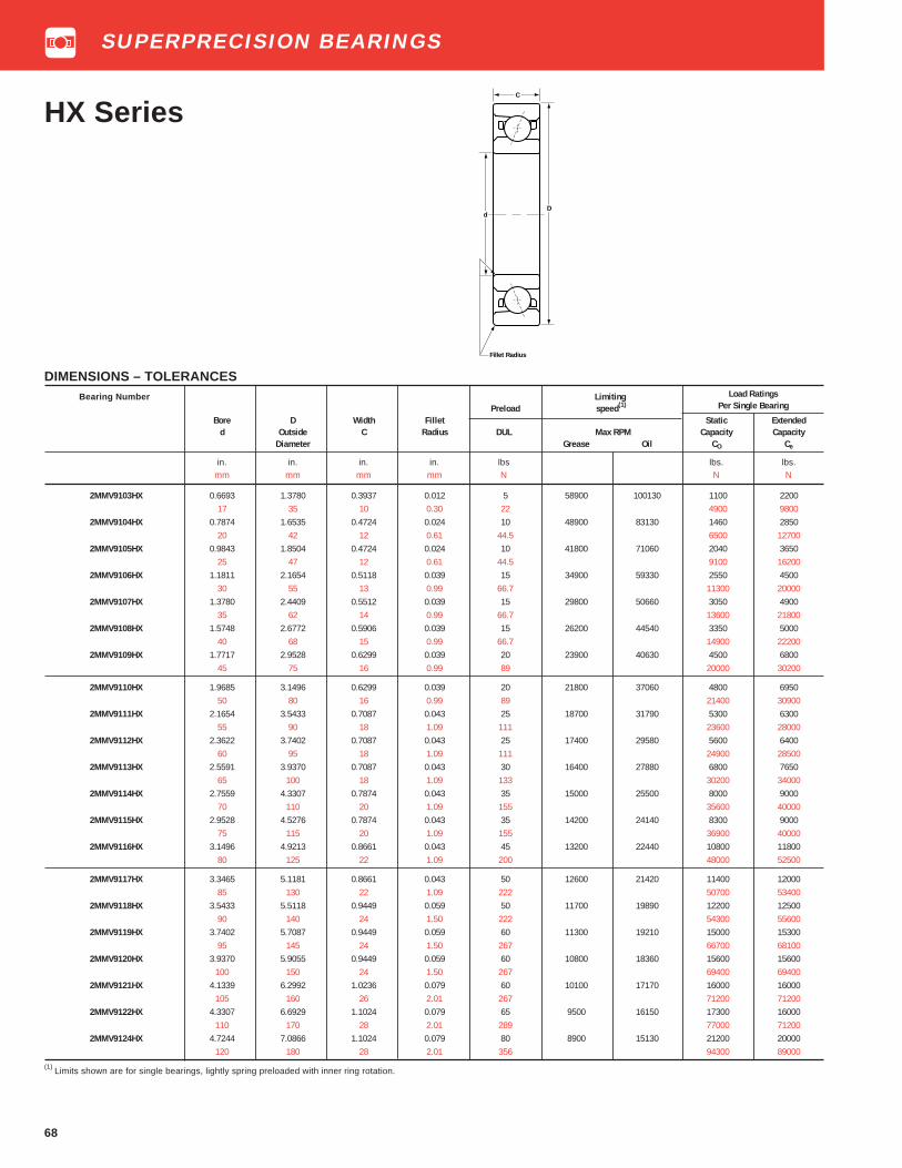
68
HX Series
Bearing Number Limiting Load Ratings
Preload speed(1) Per Single Bearing
Bore D Width Fillet Static Extendedd Outside C Radius DUL Max RPM Capacity Capacity
Diameter Grease Oil CO Ce
in. in. in. in. lbs lbs. lbs.mm mm mm mm N N N
2MMV9103HX 0.6693 1.3780 0.3937 0.012 5 58900 100130 1100 220017 35 10 0.30 22 4900 9800
2MMV9104HX 0.7874 1.6535 0.4724 0.024 10 48900 83130 1460 285020 42 12 0.61 44.5 6500 12700
2MMV9105HX 0.9843 1.8504 0.4724 0.024 10 41800 71060 2040 365025 47 12 0.61 44.5 9100 16200
2MMV9106HX 1.1811 2.1654 0.5118 0.039 15 34900 59330 2550 450030 55 13 0.99 66.7 11300 20000
2MMV9107HX 1.3780 2.4409 0.5512 0.039 15 29800 50660 3050 490035 62 14 0.99 66.7 13600 21800
2MMV9108HX 1.5748 2.6772 0.5906 0.039 15 26200 44540 3350 500040 68 15 0.99 66.7 14900 22200
2MMV9109HX 1.7717 2.9528 0.6299 0.039 20 23900 40630 4500 680045 75 16 0.99 89 20000 30200
2MMV9110HX 1.9685 3.1496 0.6299 0.039 20 21800 37060 4800 695050 80 16 0.99 89 21400 30900
2MMV9111HX 2.1654 3.5433 0.7087 0.043 25 18700 31790 5300 630055 90 18 1.09 111 23600 28000
2MMV9112HX 2.3622 3.7402 0.7087 0.043 25 17400 29580 5600 640060 95 18 1.09 111 24900 28500
2MMV9113HX 2.5591 3.9370 0.7087 0.043 30 16400 27880 6800 765065 100 18 1.09 133 30200 34000
2MMV9114HX 2.7559 4.3307 0.7874 0.043 35 15000 25500 8000 900070 110 20 1.09 155 35600 40000
2MMV9115HX 2.9528 4.5276 0.7874 0.043 35 14200 24140 8300 900075 115 20 1.09 155 36900 40000
2MMV9116HX 3.1496 4.9213 0.8661 0.043 45 13200 22440 10800 1180080 125 22 1.09 200 48000 52500
2MMV9117HX 3.3465 5.1181 0.8661 0.043 50 12600 21420 11400 1200085 130 22 1.09 222 50700 53400
2MMV9118HX 3.5433 5.5118 0.9449 0.059 50 11700 19890 12200 1250090 140 24 1.50 222 54300 55600
2MMV9119HX 3.7402 5.7087 0.9449 0.059 60 11300 19210 15000 1530095 145 24 1.50 267 66700 68100
2MMV9120HX 3.9370 5.9055 0.9449 0.059 60 10800 18360 15600 15600100 150 24 1.50 267 69400 69400
2MMV9121HX 4.1339 6.2992 1.0236 0.079 60 10100 17170 16000 16000105 160 26 2.01 267 71200 71200
2MMV9122HX 4.3307 6.6929 1.1024 0.079 65 9500 16150 17300 16000110 170 28 2.01 289 77000 71200
2MMV9124HX 4.7244 7.0866 1.1024 0.079 80 8900 15130 21200 20000120 180 28 2.01 356 94300 89000
(1) Limits shown are for single bearings, lightly spring preloaded with inner ring rotation.
DIMENSIONS – TOLERANCES
C
Dd
Fillet Radius
SUPERPRECISION BEARINGS

69
Ceramic Hybrid Bearings
A ceramic hybrid bearing is a combination of ceramic balls withstandard steel rings and retainer material appropriate for theapplication
5x
1.5x1000 –
100 –
10 –
1 –
0.1 –.5 1.0 1.5 2.0 DN (millions)
Hours x 1000
LIFE vs BALL MATERIAL2MMV99110WN DUL (DB Mounting)
CERAMIC BEARING BENEFITS• High SpeedUp to three million DN withreduced skidding, wear and heatgeneration; grease-lubricatedhybrids up to one million DN.
• Extended Fatigue LifeThree to five times greater thansteel when properly applied.
• Marginal LubricationUnique tribological featuresenhance operation under lowlubrication conditions and extendlife and speed capabilities oflubricants.
• Corrosion resistanceVirtually inert silicone nitrideresists corrosion and galling whilethin-dense-chrome coating may beused to enhance hybrid results.
• High StiffnessModulus of elasticity 50 percentgreater than steel increasesbearing rigidity.
• Low TorqueLow friction, even under marginallubrication, with extremely finesurface finishes of .1 to .2 micro-inch AA.
• Long Wear LifeHigh hardness of Rc78 greatlyextends bearing wear characteris-tics.
• Light Weight60 percent lighter than steel,reducing centrifugal forces andoverall system weight.
• Special PropertiesAll silicon nitride components are:
– non-magnetic– electrically insulative
APPLICATIONS• Aerospace
– gas and air turbines– gearboxes– auxiliary power units/
generators– valves and nozzles
• Machine Tools– ultra and high-speed milling
spindles– ultra and high-speed
grinding spindles– extended life units
• Instruments– gyro, gimbal and platform– spectroscopy
• Biotechnology– rotating anode– medical centrifuge
• Defense– space– radar– missiles
• Automotive– turbochargers
• General Industry– pumps and compressors– reactors and mixers– chemical processing– cryogenic
Industry’s present day applications place demands on machinery thatcould not be imagined as little as a decade ago.
Machinery is expected to be more efficient, reliable, faster and lastlonger with less maintenance. In the future, even the great reliability andwide versatility of the standard Torrington steel bearing may be chal-lenged.
By incorporating ceramic and state-of-the-art bearing technology, TheTorrington Company has developed the hybrid ceramic bearing.Designed with increased speed capabilities, the hybrid ceramic bearingfeatures a higher elastic modulus for greater stiffness. Its lower frictioncharacteristics result in less skidding than the all-steel bearing.
The Torrington Company Sales Engineering professional in your areacan assist you in determining if the hybrid ceramic bearing is suitable foryour application.
When ordering a ceramic hybrid bearing add “C” to the part numberafter the prefix that specifies precision type, i.e. 2MMVC99110.
Density Rigidity Friction Fracture ThermalLimit Expansion
Steel Ceramic
MATERIAL PROPERTIES100 -
90 -
80 -
70 -
60 -
50 -
40 -
30 -
20 -
10 -
0 -
Si3N4
52100steel
16 –
14 –
12 –
10 –
8 –
6 –
4 –
2 –
0 –
Tem
per
atu
re R
ise
(C)
52100 Steel Balls
CeramicBalls
5000 10000 15000 20000 25000 30000Spindle Speed (RPM)
TEMPERATURE vs SPEED2MMV99110WN (50 mm bore). Grease lubrication.
SUPERPRECISION BEARINGS
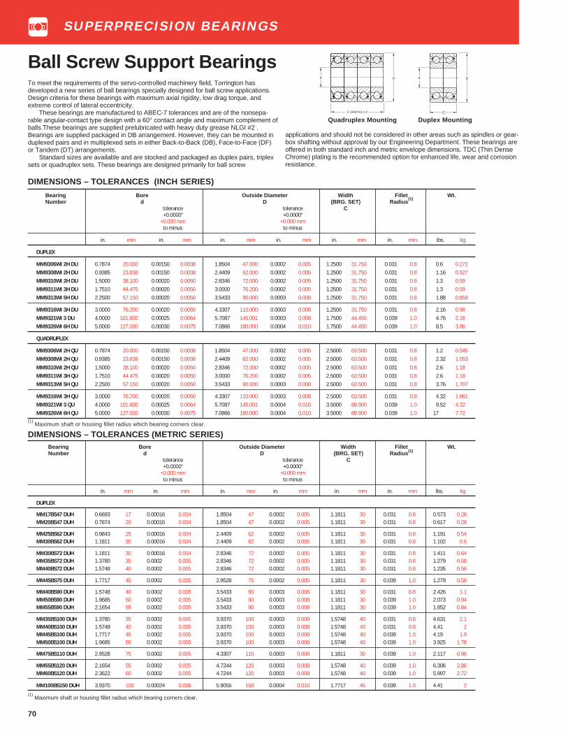
70
Bearing Bore Outside Diameter Width Fillet Wt.Number d D (BRG. SET) Radius (1)
tolerance tolerance C+0.0000" +0.0000"
+0.000 mm +0.000 mmto minus to minus
in. mm in. mm in. mm in. mm in. mm in. mm lbs. kg
DUPLEX
MM17BS47 DUH 0.6693 17 0.00016 0.004 1.8504 47 0.0002 0.005 1.1811 30 0.031 0.8 0.573 0.26MM20BS47 DUH 0.7874 20 0.00016 0.004 1.8504 47 0.0002 0.005 1.1811 30 0.031 0.8 0.617 0.28
MM25BS62 DUH 0.9843 25 0.00016 0.004 2.4409 62 0.0002 0.005 1.1811 30 0.031 0.8 1.191 0.54MM30BS62 DUH 1.1811 30 0.00016 0.004 2.4409 62 0.0002 0.005 1.1811 30 0.031 0.8 1.102 0.5
MM30BS72 DUH 1.1811 30 0.00016 0.004 2.8346 72 0.0002 0.005 1.1811 30 0.031 0.8 1.411 0.64MM35BS72 DUH 1.3780 35 0.0002 0.005 2.8346 72 0.0002 0.005 1.1811 30 0.031 0.8 1.279 0.58MM40BS72 DUH 1.5748 40 0.0002 0.005 2.8346 72 0.0002 0.005 1.1811 30 0.031 0.8 1.235 0.56
MM45BS75 DUH 1.7717 45 0.0002 0.005 2.9528 75 0.0002 0.005 1.1811 30 0.039 1.0 1.279 0.58
MM40BS90 DUH 1.5748 40 0.0002 0.005 3.5433 90 0.0003 0.008 1.1811 30 0.031 0.8 2.426 1.1MM50BS90 DUH 1.9685 50 0.0002 0.005 3.5433 90 0.0003 0.008 1.1811 30 0.039 1.0 2.073 0.94MM55BS90 DUH 2.1654 55 0.0002 0.005 3.5433 90 0.0003 0.008 1.1811 30 0.039 1.0 1.852 0.84
MM35BS100 DUH 1.3780 35 0.0002 0.005 3.9370 100 0.0003 0.008 1.5748 40 0.031 0.8 4.631 2.1MM40BS100 DUH 1.5748 40 0.0002 0.005 3.9370 100 0.0003 0.008 1.5748 40 0.031 0.8 4.41 2MM45BS100 DUH 1.7717 45 0.0002 0.005 3.9370 100 0.0003 0.008 1.5748 40 0.039 1.0 4.19 1.9MM50BS100 DUH 1.9685 50 0.0002 0.005 3.9370 100 0.0003 0.008 1.5748 40 0.039 1.0 3.925 1.78
MM75BS110 DUH 2.9528 75 0.0002 0.005 4.3307 110 0.0003 0.008 1.1811 30 0.039 1.0 2.117 0.96
MM55BS120 DUH 2.1654 55 0.0002 0.005 4.7244 120 0.0003 0.008 1.5748 40 0.039 1.0 6.306 2.86MM60BS120 DUH 2.3622 60 0.0002 0.005 4.7244 120 0.0003 0.008 1.5748 40 0.039 1.0 5.997 2.72
MM100BS150 DUH 3.9370 100 0.00024 0.006 5.9055 150 0.0004 0.010 1.7717 45 0.039 1.0 4.41 2
(1) Maximum shaft or housing fillet radius which bearing corners clear.
Bearing Bore Outside Diameter Width Fillet Wt.Number d D (BRG. SET) Radius
(1)
tolerance tolerance C+0.0000" +0.0000"
+0.000 mm +0.000 mmto minus to minus
in. mm in. mm in. mm in. mm in. mm in. mm lbs. kg
DUPLEX
MM9306WI 2H DU 0.7874 20.000 0.00150 0.0038 1.8504 47.000 0.0002 0.005 1.2500 31.750 0.031 0.8 0.6 0.272MM9308WI 2H DU 0.9385 23.838 0.00150 0.0038 2.4409 62.000 0.0002 0.005 1.2500 31.750 0.031 0.8 1.16 0.527MM9310WI 2H DU 1.5000 38.100 0.00020 0.0050 2.8346 72.000 0.0002 0.005 1.2500 31.750 0.031 0.8 1.3 0.59MM9311WI 3H DU 1.7510 44.475 0.00020 0.0050 3.0000 76.200 0.0002 0.005 1.2500 31.750 0.031 0.8 1.3 0.59MM9313WI 5H DU 2.2500 57.150 0.00020 0.0050 3.5433 90.000 0.0003 0.008 1.2500 31.750 0.031 0.8 1.88 0.859
MM9316WI 3H DU 3.0000 76.200 0.00020 0.0050 4.3307 110.000 0.0003 0.008 1.2500 31.750 0.031 0.8 2.16 0.98MM9321WI 3 DU 4.0000 101.600 0.00025 0.0064 5.7087 145.001 0.0003 0.008 1.7500 44.450 0.039 1.0 4.76 2.16MM9326WI 6H DU 5.0000 127.000 0.00030 0.0075 7.0866 180.000 0.0004 0.010 1.7500 44.450 0.039 1.0 8.5 3.86
QUADRUPLEX
MM9306WI 2H QU 0.7874 20.000 0.00150 0.0038 1.8504 47.000 0.0002 0.005 2.5000 63.500 0.031 0.8 1.2 0.545MM9308WI 2H QU 0.9385 23.838 0.00150 0.0038 2.4409 62.000 0.0002 0.005 2.5000 63.500 0.031 0.8 2.32 1.053MM9310WI 2H QU 1.5000 38.100 0.00020 0.0050 2.8346 72.000 0.0002 0.005 2.5000 63.500 0.031 0.8 2.6 1.18MM9311WI 3H QU 1.7510 44.475 0.00020 0.0050 3.0000 76.200 0.0002 0.005 2.5000 63.500 0.031 0.8 2.6 1.18MM9313WI 5H QU 2.2500 57.150 0.00020 0.0050 3.5433 90.000 0.0003 0.008 2.5000 63.500 0.031 0.8 3.76 1.707
MM9316WI 3H QU 3.0000 76.200 0.00020 0.0050 4.3307 110.000 0.0003 0.008 2.5000 63.500 0.031 0.8 4.32 1.961MM9321WI 3 QU 4.0000 101.600 0.00025 0.0064 5.7087 145.001 0.0004 0.010 3.5000 88.900 0.039 1.0 9.52 4.32MM9326WI 6H QU 5.0000 127.000 0.00030 0.0075 7.0866 180.000 0.0004 0.010 3.5000 88.900 0.039 1.0 17 7.72
(1) Maximum shaft or housing fillet radius which bearing corners clear.
DIMENSIONS – TOLERANCES (METRIC SERIES)
Ball Screw Support BearingsTo meet the requirements of the servo-controlled machinery field, Torrington hasdeveloped a new series of ball bearings specially designed for ball screw applications.Design criteria for these bearings with maximum axial rigidity, low drag torque, andextreme control of lateral eccentricity.
These bearings are manufactured to ABEC-7 tolerances and are of the nonsepa-rable angular-contact type design with a 60° contact angle and maximum complement ofballs.These bearings are supplied prelubricated with heavy duty grease NLGI #2 .Bearings are supplied packaged in DB arrangement. However, they can be mounted induplexed pairs and in multiplexed sets in either Back-to-Back (DB), Face-to-Face (DF)or Tandem (DT) arrangements.
Standard sizes are available and are stocked and packaged as duplex pairs, triplexsets or quadruplex sets. These bearings are designed primarily for ball screw
DIMENSIONS – TOLERANCES (INCH SERIES)
d D
C (WIDTH) X 2
d D
Quadruplex Mounting Duplex Mounting
applications and should not be considered in other areas such as spindles or gear-box shafting without approval by our Engineering Department. These bearings areoffered in both standard inch and metric envelope dimensions. TDC (Thin DenseChrome) plating is the recommended option for enhanced life, wear and corrosionresistance.
C
SUPERPRECISION BEARINGS

71
SUPERPRECISION BEARINGS
PHYSICAL CHARACTERISTICS – LOAD RATINGSBearing Std. System Axial Spring Drag Torque of Extended Thrust (C AE) Limiting ThrustNumber Preload (P L) Constant Preloaded Set Dynamic Load Rating Capacity (T L)
lbs. N X106lbs/in. N/m lbs./in. Nm lbs. N lbs. N
DUPLEX
MM9306WI2H DUH 700 3110 4.3 750 3 0.034 5600 25000 5600 25000MM17BS47 DUHMM20BS47 DUH
MM9308WI2H DUH 1000 4450 6.0 1100 4 0.045 6550 29000 8000 35500MM25BS62 DUHMM30BS62 DUH
MM9310WI2H DUH 1400 6320 7.9 1390 5 0.056 8000 36000 10200 45500MM30BS72 DUHMM35BS72 DUHMM40BS72 DUH
MM35BS100 DUH 2900 12,900 10.0 1760 2 0.28 21500 96000 15700 70500MM40BS100 DUHMM45BS100 DUHMM50BS100 DUH
MM9311WI3H DUH 1500 6670 7.9 1390 5 0.56 8500 38000 11400 51000
MM9313WI5H DUH 1800 8010 9.4 1655 7 0.79 9150 40500 13700 61000MM40BS90 DUHMM50BS90 DUHMM55BS90 DUH
MM9316WI3H DUH 2200 9790 11.9 2100 9 1.02 10000 44000 17300 76500MM75BS110 DUH
MM9321WI3 DUH 4800 21350 14 2455 12 1.36 19000 85000 34000 150000
MM9326WI6H DUH 6000 26690 18.0 3150 23 2.27 20600 91600 42000 186000
MM55BS120DUH 3500 15570 12.0 2150 6 0.68 18000 80800 26400 117800MM60BS120 DUH
MM100BS150 DUH 4800 21350 16.4 2900 10 1.09 19400 86400 33800 151300
QUADRUPLEX
MM9306WI2H QUH 1400 6230 8.6 1500 6 0.068 11200 50000 11200 50000MM17BS47 QUHMM20BS47 QUH
MM9308WI2H QUH 2000 8900 12 2200 8 0.9 13100 58000 16000 71000MM25BS62H QUHMM30BS62H QUH
MM9310WI2H QUH 2800 12450 15.8 2780 10 1.12 16000 72000 20400 91000MM30BS72 QUHMM35BS72 QUHMM40BS72 QUH
MM35BS100 QUH 5800 25800 20.0 3520 4 0.56 43000 192000 31400 141000MM40BS100 QUHMM45BS100 QUHMM50BS100 QUH
MM9311WI3H QUH 3000 13340 15.8 2780 10 1.12 17000 76000 22800 102000
MM9313WI5H QUH 3600 16010 18.8 3310 14 1.58 18300 81000 27400 122000MM40BS90 QUHMM50BS90 QUHMM55BS90 QUH
MM9316WI3H QUH 4400 19570 23.8 4200 18 2.04 20000 88000 34600 153000MM75BS110 QUH
MM9321WI3 QUH 9600 42700 28.4 4910 24 2.72 38000 170000 68000 300000
MM9326WI6H QUH 12000 53380 36.0 6300 40 4.5 41200 183200 84000 372000
MM55BS120 QUH 7000 31140 24.0 4300 12 1.36 36000 161600 52800 235600MM60BS120 QUH
MM100BS150 QUH 9600 42700 32.8 6720 20 2.18 38800 172800 67600 302600
Ball Screw Support SeriesThe recommended maximum limitations on ball screw bearing speedlimits are based on 50% active duty cycle and a ten minute total cycleperiod. Speed limitations may be increased somewhat with lighter
duty cycles. Please consult our Engineering Department regardingbearing speeds and duty cycles.

72
SUPERPRECISION BEARINGS
Ball Screw Support Series
SHAFT AND HOUSING DIAMETERSMETRIC SERIES
Bearing Bearing Shaft Bearing Housing Bearing Bearing Shaft Bearing HousingNumber Bore O.D. Number Bore O.D.
in. mm in. mm in. mm in. mm in. mm in. mm in. mm in. mm
MM17BS 47 0.66929 17.000 0.66917 16.991 1.8504 47.000 1.8507 47.008 MM45BS 75 1.7716 45.000 1.7714 44.995 2.9527 75.000 2.9531 75.0080.66913 16.996 0.66897 16.992 1.8502 46.995 1.8504 47.000 1.7714 44.995 1.7712 44.990 2.9525 74.995 2.9527 75.000
MM20BS 47 0.7874 20.000 0.78728 19.997 1.8504 47.000 1.8507 47.008 MM45BS 100 1.7716 45.000 1.7714 44.995 3.937 100.000 3.9374 100.0100.78725 19.996 0.78708 19.992 1.8502 46.995 1.8504 47.000 1.7714 44.995 1.7712 44.990 3.9366 99.992 3.937 100.000
MM25BS 62 0.98425 25.000 0.98413 24.997 2.4409 62.000 2.4412 62.008 MM50BS 90 1.9685 50.000 1.9683 49.995 3.5433 90.000 3.5436 90.0080.98409 24.996 0.98393 24.992 2.4407 61.995 2.4409 62.000 1.9683 49.995 1.9681 49.990 3.5429 89.992 3.5433 90.000
MM30BS 62 1.1811 30.000 1.1809 29.997 2.4409 62.000 2.4412 62.008 MM50BS 100 1.9685 50.000 1.9683 49.995 3.937 100.000 3.9374 100.0101.1809 29.996 1.1807 29.992 2.4407 61.995 2.4409 62.000 1.9683 49.995 1.9681 44.990 3.9366 99.992 3.937 100.000
MM30BS 72 1.1811 30.000 1.1809 29.997 2.8346 72.000 2.8349 72.008 MM55BS 90 2.1653 55.000 2.1651 54.995 3.5433 90.000 3.5436 90.0081.1809 29.996 1.1807 29.992 2.8344 71.995 2.8346 72.000 2.1651 54.995 2.1649 54.990 3.5429 89.992 3.5433 90.000
MM35BS 72 1.3779 35.000 1.3777 34.995 2.8346 72.000 2.8349 72.008 MM55BS 120 2.1653 55.000 2.1651 54.995 4.7244 120.000 4.7248 120.0101.3777 34.995 1.3775 34.990 2.8344 71.995 2.8346 72.000 2.1651 54.995 2.1649 54.990 4.7241 119.992 4.7244 120.000
MM35BS 100 1.3779 35.000 1.3777 34.995 3.9370 100.000 3.9374 100.010 MM60BS 120 2.3622 60.000 2.3620 59.995 4.7244 120.000 4.7248 120.0101.3777 34.995 1.3775 34.990 3.9366 99.992 3.9370 100.000 2.3620 59.995 2.3618 59.990 4.7241 119.992 4.7244 120.000
MM40BS 72 1.5748 40.000 1.5746 39.995 2.8346 72.000 2.8349 72.008 MM75BS 110 2.9527 75.000 2.9525 74.995 4.3307 110.000 4.3311 110.0101.5746 39.995 1.5744 39.990 2.8344 71.995 2.8346 72.000 2.9525 74.995 2.9522 74.987 4.3304 109.992 4.3307 110.000
MM40BS 90 1.5748 40.000 1.5746 39.995 3.5433 90.000 3.5436 90.008 MM100BS 150 3.9370 100.000 3.9368 99.995 5.9055 150.000 5.9059 150.0101.5746 39.995 1.5744 39.990 3.5429 89.992 3.5433 90.000 3.9367 99.940 3.9364 99.987 5.9051 149.990 5.9055 150.000
MM40BS 100 1.5748 40.000 1.5746 39.995 3.9370 100.000 3.9374 100.0101.5746 39.995 1.5744 39.990 3.9366 99.992 3.9370 100.000
SHAFT AND HOUSING DIAMETERSINCH SERIES
Bearing Bearing Shaft Bearing HousingNumber Bore O.D.
in. mm in. mm in. mm in. mm
MM9306WI 2H 0.7874 20 0.7873 19.997 1.8504 47 1.8507 47.0080.78725 19.996 0.7871 19.992 1.8502 46.995 1.8504 47.000
MM9308WI 2H 0.9385 23.8379 0.9384 23.835 2.4409 62 2.4412 62.0080.93835 23.6341 0.9382 28.830 2.4407 61.995 2.4409 62.000
MM9310WI 2H 1.5000 38.100 1.4998 38.095 2.8346 72 2.8349 72.0081.4998 38.095 1.4996 38.090 2.8344 71.995 2.8346 72.000
MM9311WI 3H 1.7510 44.475 1.7508 44.470 3.0000 76.2 3.0003 76.2081.7508 44.470 1.7506 44.465 2.9998 76.195 3.0000 76.200
MM9313WI 5H 2.2500 57.150 2.2498 57.145 3.5433 90 3.5436 90.0082.2498 57.145 2.2496 57.140 3.5431 89.995 3.5433 90.000
MM9316WI 3H 3.0000 76.200 2.9998 76.195 4.3307 110 4.3311 110.0102.9998 76.195 2.9995 76.187 4.3304 109.992 4.3307 110.000
MM9321WI 3 4.0000 101.600 3.9998 101.595 5.7091 145 5.7087 145.0103.99975 101.5936 3.9995 101.587 5.7030 145.99 5.7084 145.000
MM9326WI 6H 5.0000 127.000 4.9997 126.985 7.0866 179.986 7.0870 179.9964.9997 126.985 4.9994 126.975 7.0862 179.976 7.0866 179.986

73
SUPERPRECISION BEARINGS
Ball Screw Support Series
SHAFT AND HOUSING SHOULDER DIMENSIONSMETRIC SERIES
Bearing Shaft Housing Fillet Bearing Shaft Housing FilletSize ± .005" ± .005" Radius Size ± .005" ± .005" Radius
± .13mm ± .13mm (max.) ± .13mm ± .13mm (max.)
in. mm in. mm in. mm in. mm in. mm in. mm
MM17BS 47 0.905 23.00 1.634 41.5 0.031 0.8 MM45BS 75 2.047 52.00 2.717 69.00 0.03 1.0MM20BS 47 1.024 26.00 1.634 41.5 0.031 0.8 MM45BS 100 2.126 54.00 3.543 90.00 0.03 1.0
MM25BS 62 1.378 35.00 2.205 56.0 0.031 0.8 MM50BS 90 2.323 59.00 3.228 82.00 0.03 1.0MM30BS 62 1.575 40.00 2.205 56.0 0.031 0.8 MM50BS 100 2.323 59.00 3.543 90.00 0.03 1.0
MM30BS 72 1.575 40.00 2.205 56.0 0.031 0.8 MM55BS 90 2.48 63.00 3.228 82.00 0.03 1.0MM35BS 72 1.653 42.00 2.520 64.0 0.031 0.8 MM55BS 120 2.559 65.00 4.331 110.00 0.03 1.0
MM35BS 100 1.653 42.00 3.543 90.0 0.031 0.8 MM60BS 120 2.756 70.00 4.331 110.00 0.03 1.0MM40BS 72 1.850 47.00 2.520 64.0 0.031 0.8 MM75BS 110 3.307 84.00 4.016 102.00 0.03 1.0
MM40BS 90 1.850 47.00 3.228 82.0 0.031 0.8 MM100BS 150 4.331 110.00 5.433 138.00 0.03 1.0MM40BS 100 1.850 47.00 3.543 90.0 0.031 0.8
SHAFT AND HOUSING SHOULDER DIMENSIONSINCH SERIES
Bearing Shaft Housing FilletSize ± .005" ± .005" Radius
± .13mm ± .13mm (max.)
in. mm in. mm in. mm
MM9306WI 2H 1.059 26.90 1.613 40.90 0.031 0.8MM9308WI 2H 1.631 41.40 2.185 55.50 0.031 0.8MM9310WI 2H 1.857 47.20 2.475 62.90 0.031 0.8MM9311WI 2H 2.052 52.10 2.670 67.80 0.031 0.8MM9313WI 5H 2.574 65.40 3.192 81.10 0.031 0.8
MM9316WI 3H 3.377 85.80 3.995 101.50 0.031 0.8MM9321WI 3 4.512 114.60 5.191 131.90 0.039 1.0
MM9326WI 6H 5.664 143.90 6.602 167.70 0.039 1.0
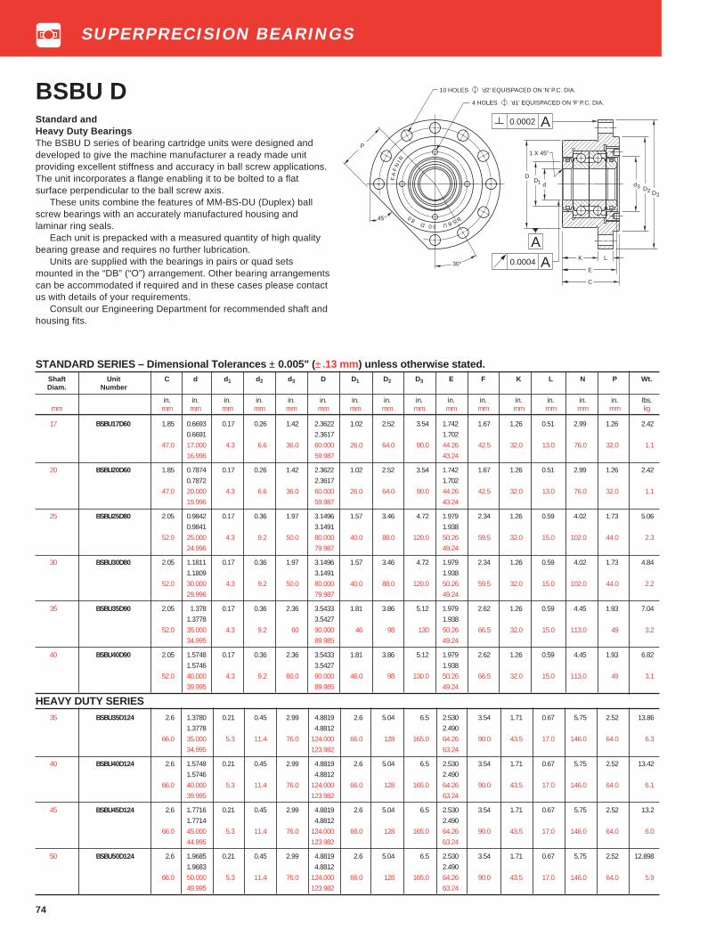
74
BSBU DStandard andHeavy Duty BearingsThe BSBU D series of bearing cartridge units were designed anddeveloped to give the machine manufacturer a ready made unitproviding excellent stiffness and accuracy in ball screw applications.The unit incorporates a flange enabling it to be bolted to a flatsurface perpendicular to the ball screw axis.
These units combine the features of MM-BS-DU (Duplex) ballscrew bearings with an accurately manufactured housing andlaminar ring seals.
Each unit is prepacked with a measured quantity of high qualitybearing grease and requires no further lubrication.
Units are supplied with the bearings in pairs or quad setsmounted in the “DB” (“O”) arrangement. Other bearing arrangementscan be accommodated if required and in these cases please contactus with details of your requirements.
Consult our Engineering Department for recommended shaft andhousing fits.
STANDARD SERIES – Dimensional Tolerances ± 0.005" (± .13 mm) unless otherwise stated.Shaft Unit C d d 1 d2 d3 D D1 D2 D3 E F K L N P Wt.Diam. Number
in. in. in. in. in. in. in. in. in. in. in. in. in. in. in. lbs.mm mm mm mm mm mm mm mm mm mm mm mm mm mm mm mm kg
17 BSBU17D60 1.85 0.6693 0.17 0.26 1.42 2.3622 1.02 2.52 3.54 1.742 1.67 1.26 0.51 2.99 1.26 2.420.6691 2.3617 1.702
47.0 17.000 4.3 6.6 36.0 60.000 26.0 64.0 90.0 44.26 42.5 32.0 13.0 76.0 32.0 1.116.996 59.987 43.24
20 BSBU20D60 1.85 0.7874 0.17 0.26 1.42 2.3622 1.02 2.52 3.54 1.742 1.67 1.26 0.51 2.99 1.26 2.420.7872 2.3617 1.702
47.0 20.000 4.3 6.6 36.0 60.000 26.0 64.0 90.0 44.26 42.5 32.0 13.0 76.0 32.0 1.119.996 59.987 43.24
25 BSBU25D80 2.05 0.9842 0.17 0.36 1.97 3.1496 1.57 3.46 4.72 1.979 2.34 1.26 0.59 4.02 1.73 5.060.9841 3.1491 1.938
52.0 25.000 4.3 9.2 50.0 80.000 40.0 88.0 120.0 50.26 59.5 32.0 15.0 102.0 44.0 2.324.996 79.987 49.24
30 BSBU30D80 2.05 1.1811 0.17 0.36 1.97 3.1496 1.57 3.46 4.72 1.979 2.34 1.26 0.59 4.02 1.73 4.841.1809 3.1491 1.938
52.0 30.000 4.3 9.2 50.0 80.000 40.0 88.0 120.0 50.26 59.5 32.0 15.0 102.0 44.0 2.229.996 79.987 49.24
35 BSBU35D90 2.05 1.378 0.17 0.36 2.36 3.5433 1.81 3.86 5.12 1.979 2.62 1.26 0.59 4.45 1.93 7.041.3778 3.5427 1.938
52.0 35.000 4.3 9.2 60 90.000 46 98 130 50.26 66.5 32.0 15.0 113.0 49 3.234.995 89.985 49.24
40 BSBU40D90 2.05 1.5748 0.17 0.36 2.36 3.5433 1.81 3.86 5.12 1.979 2.62 1.26 0.59 4.45 1.93 6.821.5746 3.5427 1.938
52.0 40.000 4.3 9.2 60.0 90.000 46.0 98 130.0 50.26 66.5 32.0 15.0 113.0 49 3.139.995 89.985 49.24
HEAVY DUTY SERIES35 BSBU35D124 2.6 1.3780 0.21 0.45 2.99 4.8819 2.6 5.04 6.5 2.530 3.54 1.71 0.67 5.75 2.52 13.86
1.3778 4.8812 2.49066.0 35.000 5.3 11.4 76.0 124.000 66.0 128 165.0 64.26 90.0 43.5 17.0 146.0 64.0 6.3
34.995 123.982 63.24
40 BSBU40D124 2.6 1.5748 0.21 0.45 2.99 4.8819 2.6 5.04 6.5 2.530 3.54 1.71 0.67 5.75 2.52 13.421.5746 4.8812 2.490
66.0 40.000 5.3 11.4 76.0 124.000 66.0 128 165.0 64.26 90.0 43.5 17.0 146.0 64.0 6.139.995 123.982 63.24
45 BSBU45D124 2.6 1.7716 0.21 0.45 2.99 4.8819 2.6 5.04 6.5 2.530 3.54 1.71 0.67 5.75 2.52 13.21.7714 4.8812 2.490
66.0 45.000 5.3 11.4 76.0 124.000 66.0 128 165.0 64.26 90.0 43.5 17.0 146.0 64.0 6.044.995 123.982 63.24
50 BSBU50D124 2.6 1.9685 0.21 0.45 2.99 4.8819 2.6 5.04 6.5 2.530 3.54 1.71 0.67 5.75 2.52 12.8981.9683 4.8812 2.490
66.0 50.000 5.3 11.4 76.0 124.000 66.0 128 165.0 64.26 90.0 43.5 17.0 146.0 64.0 5.949.995 123.982 63.24
BSBU 30 D 80
FA
FN
I R
30°
P
10 HOLES 'd2' EQUISPACED ON 'N' P.C. DIA.
4 HOLES 'd1' EQUISPACED ON 'F' P.C. DIA.
45°
DD
ddD
D
3
32
1
0.0002 A
0.0004 AA
K L
E
C
1 X 45°
SUPERPRECISION BEARINGS

75
STANDARD SERIES – Dimensional Tolerances ± 0.005" (± .13 mm) unless otherwise statedShaft Unit C d d 1 d2 d3 D D1 D2 D3 E F K L N P Wt.Diam. Number
in. in. in. in. in. in. in. in. in. in. in. in. in. in. in. lbs.mm mm mm mm mm mm mm mm mm mm mm mm mm mm mm mm kg
17 BSBU17Q60 3.03 0.6693 0.17 0.26 1.42 2.3622 1.02 2.52 3.54 2.924 1.67 1.26 0.51 2.99 1.26 3.740.6690 2.3617 2.864
77.0 17.000 4.3 6.6 36.0 60.000 26.0 64.0 90.0 74.26 42.5 32.0 13.0 76.0 32.0 1.716.993 59.987 72.74
20 BSBU20Q60 3.03 0.7874 0.17 0.26 1.42 2.3622 1.02 2.52 3.54 2.924 1.67 1.26 0.51 2.99 1.26 3.740.7872 2.3617 2.864
77.0 20.000 4.3 6.6 36.0 60.000 26.0 64.0 90.0 74.26 42.5 32.0 13.0 76.0 32.0 1.719.996 59.987 72.74
25 BSBU25Q80 3.23 0.9842 0.17 0.36 1.97 3.1496 1.57 3.46 4.72 3.160 2.34 1.26 0.59 4.02 1.73 7.70.9841 3.1491 3.100
82.0 25.000 4.3 9.2 50.0 80.000 40.0 88.0 120.0 80.26 59.5 32.0 15.0 102.0 44.0 3.524.996 79.987 78.74
30 BSBU30Q80 3.23 1.1811 0.17 0.36 1.97 3.1496 1.57 3.46 4.72 3.160 2.34 1.26 0.59 4.02 1.73 7.481.1809 3.1491 3.100
82.0 30.000 4.3 9.2 50.0 80 40.0 88.0 120.0 80.26 59.5 32.0 15.0 102.0 44.0 3.429.995 79.987 78.74
35 BSBU35Q90 3.23 1.3780 0.17 0.36 2.36 3.5433 1.81 3.86 5.12 3.160 2.62 1.26 0.59 4.45 1.93 10.121.3778 3.5427 3.100
82.0 40.000 4.3 9.2 60 90.000 46 98 130 80.26 66.5 32.0 15.0 113.0 49 4.639.000 89.985 78.74
40 BSBU40Q90 3.23 1.5748 0.17 0.36 2.36 3.5433 1.81 3.86 5.12 3.160 2.62 1.26 0.59 4.45 1.93 9.91.5746 3.5427 3.100
82.0 40.000 4.3 9.2 60.0 90.000 46.0 98 130.0 80.26 66.5 32.0 15.0 113.0 49 4.539.995 89.985 78.74
HEAVY DUTY SERIES35 BSBU35Q124 4.17 1.3780 0.21 0.45 2.99 4.8819 2.6 5.04 6.5 4.105 3.54 1.71 0.67 5.75 2.52 22.22
1.3778 4.8812 4.045106.0 35.000 5.3 11.4 76.0 124.000 66.0 128 165.0 104.26 90.0 43.5 17.0 146.0 64.0 10.1
34.995 123.982 102.74
40 BSBU40Q124 4.17 1.5748 0.21 0.45 2.99 4.8819 2.6 5.04 6.5 4.105 3.54 1.71 0.67 5.75 2.52 21.341.5746 4.8812 4.045
106.0 40.000 5.3 11.4 76.0 124.000 66.0 128 165.0 104.26 90.0 43.5 17.0 146.0 64.0 9.739.995 123.982 102.74
45 BSBU45Q124 4.17 1.7716 0.21 0.45 2.99 4.8819 2.6 5.04 6.5 4.105 3.54 1.71 0.67 5.75 2.52 20.91.7714 4.8812 4.045
106.0 45.000 5.3 11.4 76.0 124.000 66.0 128 165.0 104.26 90.0 43.5 17.0 146.0 64.0 9.544.995 123.982 102.74
50 BSBU50Q124 4.17 1.9685 0.21 0.45 2.99 4.8819 2.6 5.04 6.5 4.105 3.54 1.71 0.67 5.75 2.52 20.461.9683 4.8812 4.045
106.0 50.000 5.3 11.4 76.0 124.000 66.0 128 165.0 104.26 90.0 43.5 17.0 146.0 64.0 9.349.995 123.982 102.74
BSBU QStandard andHeavy Duty BearingsThe BSBU Q series are similar in design and features to the BSBU Dseries except MM-BS-QU Quadruplex bearings are used.
Consult our Engineering Department for recommended shaft andhousing fits.
FA
FN
I R
BSBU 30 Q 80
30°
P
10 HOLES 'd2' EQUISPACED ON 'N' P.C. DIA.
4 HOLES 'd1' EQUISPACED ON 'F' P.C. DIA.
dD
D1
0.0002 A
0.0004 AA
K L
E
C
1 X 45°
DD
d3
32
45°
SUPERPRECISION BEARINGS
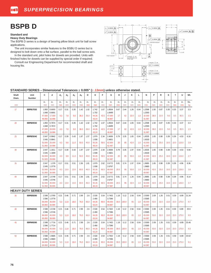
76
BSPB DStandard andHeavy Duty BearingsThe BSPB D series is a design of bearing pillow block unit for ball screwapplications.
The unit incorporates similar features to the BSBU D series but isdesigned to bolt down onto a flat surface, parallel to the ball screw axis.
In the standard unit, pilot holes for dowels are provided. Units withfinished holes for dowels can be supplied by special order if required.
Consult our Engineering Department for recommended shaft andhousing fits.
STANDARD SERIES – Dimensional Tolerances ± 0.005" (± .13mm) unless otherwise stated.Shaft Unit C d d 1 d2 d3 d4 D E F G H J K L N P R S T U Wt.
Diam. Number
in. in. in. in. in. in. in. in. in. in. in. in. in. in. in. in. in. in. in. in. lbs.mm mm mm mm mm mm mm mm mm mm mm mm mm mm mm mm mm mm mm mm mm kg
17 BSPB17D32 1.850 0.6693 0.17 0.31 0.35 1.42 1.02 1.742 1.67 1.8504 0.67 2.44 1.26 0.04 1.2598 1.50 0.87 0.35 0.33 3.37 3.31.848 0.6691 1.702 1.8499 1.2593
47.000 17.000 4.3 7.8 9.0 36.0 26.0 44.26 42.5 47.000 17 62 32.0 1.0 32.000 38.0 22.0 9.0 8.5 85.5 1.546.950 16.996 43.24 46.987 31.987
20 BSPB20D32 1.850 0.7874 0.17 0.31 0.35 1.42 1.02 1.742 1.67 1.8504 0.67 2.44 1.65 0.04 1.2598 1.50 0.87 0.35 0.33 3.37 3.31.848 0.7872 1.702 1.8499 1.2593
47.000 20.000 4.3 7.8 9.0 36.0 26.0 44.26 42.5 47.000 17 62 42.0 1.0 32.000 38.0 22.0 9.0 8.5 85.5 1.546.950 19.996 43.24 46.987 31.987
25 BSPB25D42 2.047 0.9842 0.17 0.39 0.43 1.97 1.57 1.979 2.34 2.4606 0.79 3.35 1.65 0.04 1.6535 1.65 0.98 0.39 0.39 4.53 6.162.045 0.9841 1.938 2.4601 1.6530
52.000 25.000 4.3 9.8 11.0 50.0 40.0 50.26 59.5 62.500 20 85 42.0 1.0 42.000 42.0 25.0 10.0 10.0 115.0 2.851.950 24.996 49.24 62.487 41.987
30 BSPB30D42 2.047 1.1811 0.17 0.39 0.43 1.97 1.57 1.979 2.34 2.4606 0.79 3.35 1.97 0.04 1.6535 1.65 0.98 0.39 0.39 4.53 5.942.045 1.1809 1.938 2.4601 1.6530
52.000 30.000 4.3 9.8 11.0 50.0 40.0 50.26 59.5 62.500 20 85 50.0 1.0 42.000 42.0 25.0 10.0 10.0 115.0 2.751.920 29.996 49.24 62.487 41.987
35 BSPB35D50 2.047 1.378 0.17 0.51 0.51 2.36 1.81 1.979 2.62 2.6772 0.81 3.74 1.97 0.04 1.9685 1.65 0.98 0.39 0.39 4.96 8.362.045 1.3778 1.938 2.6767 1.9680
52.000 35.000 4.3 13.0 13.0 60.0 46.0 50.26 66.5 68.000 20.5 95 50.0 1.0 50.000 42.0 25.0 10.0 10.0 126.0 3.851.950 34.995 49.24 67.987 49.987
40 BSPB40D50 2.047 1.5748 0.17 0.51 0.51 2.36 1.81 1.979 2.62 2.6772 0.81 3.74 1.26 0.04 1.9685 1.65 0.98 0.39 0.39 4.96 8.142.045 1.5746 1.938 2.6767 1.9680
52.000 40.000 4.3 13.0 13.0 60.0 46.0 50.26 66.5 68.000 20.5 95 32.0 1.0 50.000 42.0 25.0 10.0 10.0 126.0 3.751.950 39.995 49.24 67.987 49.987
HEAVY DUTY SERIES35 BSPB35D65 2.598 1.3780 0.21 0.46 0.71 2.99 2.6 2.530 3.54 3.7402 1.18 5.12 2.56 0.04 2.5590 2.09 1.26 0.51 0.59 6.89 21.34
2.596 1.3778 2.490 3.7396 2.558566.000 35.000 5.3 11.8 18.0 76.0 66.0 64.26 90.0 95.000 30.0 130.0 65 1.0 65.000 53.0 32.0 13.0 15.0 175.0 9.765.950 34.995 63.24 94.987 64.987
40 BSPB40D65 2.598 1.5748 0.21 0.46 0.71 2.99 2.6 2.530 3.54 3.7402 1.18 5.12 2.56 0.04 2.5590 2.09 1.26 0.51 0.59 6.89 20.92.596 1.5746 2.490 3.7396 2.5585
66.000 40.000 5.3 11.8 18.0 76.0 66.0 64.26 90.0 95.000 30.0 130.0 65 1.0 65.000 53.0 32.0 13.0 15.0 175.0 9.565.950 39.995 63.24 94.987 64.987
45 BSPB45D65 2.598 1.7716 0.21 0.46 0.71 2.99 2.6 2.530 3.54 3.7402 1.18 5.12 2.56 0.04 2.5590 2.09 1.26 0.51 0.59 6.89 20.462.596 1.7714 2.490 3.7396 2.5585
66.000 45.000 5.3 11.8 18.0 76.0 66.0 64.26 90.0 95.000 30.0 130.0 65 1.0 65.000 53.0 32.0 13.0 15.0 175.0 9.365.950 44.995 63.24 94.987 64.987
50 BSPB50D65 2.598 1.9685 0.21 0.46 0.71 2.99 2.6 2.530 3.54 3.7402 1.18 5.12 2.56 0.04 2.5590 2.09 1.26 0.51 0.59 6.89 20.022.596 1.9683 2.490 3.7396 2.5585
66.000 50.000 5.3 11.8 18.0 76.0 66.0 64.26 90.0 95.000 30.0 130.0 65 1.0 65.000 53.0 32.0 13.0 15.0 175.0 9.165.950 49.995 63.24 94.987 64.987
B
AA
4 HOLES 'd1' EQUISPACED ON 'F' P.C. DIA.
G
H
H
A
N
L
CENTER HEIGHT
G
H
K
H
J
A0.0004
FOOT HEIGHT A
dd
4
1 X 45°
A B
C
E
U
T
SR
P
0.0008
4 HOLES 'd3'
2 HOLES 'd2'
D
0.0004 0.0004
0.0004
0.0004
0.0008
SUPERPRECISION BEARINGS

77
BSPB Q SeriesStandard andHeavy Duty BearingsThe BSPB Q series is similar in design and features to the BSPB Dseries except MM-BS-QU Quadruplex bearings are used.
Consult our Engineering Department for recommended shaft andhousing fits.
STANDARD SERIES – Dimensional Tolerances ± 0.005" (± .13 mm) unless otherwise statedShaft Unit C d d 1 d2 d3 d4 D E F G H J K L N P R S T U Wt.Diam. Number
in. in. in. in. in. in. in. in. in. in. in. in. in. in. in. in. in. in. in. in. lbs.mm mm mm mm mm mm mm mm mm mm mm mm mm mm mm mm mm mm mm mm mm kg
17 BSPB17Q32 3.031 0.6693 0.17 0.31 0.35 1.42 1.02 2.924 1.67 1.8504 0.67 2.44 1.26 0.04 1.2598 2.68 0.87 0.35 0.33 3.37 5.723.030 0.6691 2.864 1.8499 1.2593
77.000 17.000 4.3 7.8 9.0 36.0 26.0 74.26 42.5 47.000 17 62 32.0 1.0 32.000 68.0 22.0 9.0 8.5 85.5 2.676.950 16.996 72.74 46.987 31.987
20 BSPB20Q32 3.031 0.7874 0.17 0.31 0.35 1.42 1.02 2.924 1.67 1.8504 0.67 2.44 1.26 0.04 1.2598 2.68 0.87 0.35 0.33 3.37 5.53.030 0.7872 2.864 1.8499 1.2593
77.000 20.000 4.3 7.8 9.0 36.0 26.0 74.26 42.5 47.000 17 62 32.0 1.0 32.000 68.0 22.0 9.0 8.5 85.5 2.576.950 19.996 72.74 46.987 31.987
25 BSPB25Q42 3.228 0.9842 0.17 0.39 0.43 1.97 1.57 3.160 2.34 2.4606 0.79 3.35 1.65 0.04 1.6535 2.83 0.98 0.39 0.39 4.53 10.123.226 0.9841 3.100 2.4601 1.6530
82.000 25.000 4.3 9.8 11.0 50.0 40.0 80.26 59.5 62.500 20 85 42.0 1.0 42.000 72.0 25.0 10.0 10.0 115.0 4.681.950 24.995 78.74 62.487 41.987
30 BSPB30Q42 3.228 1.1811 0.17 0.39 0.43 1.97 1.57 3.160 2.34 2.4606 0.79 3.35 1.65 0.04 1.6535 2.83 0.98 0.39 0.39 4.53 9.93.226 1.1809 3.100 2.4601 1.6530
82.000 30.000 4.3 9.8 11.0 50.0 40.0 80.26 59.5 62.500 20 85 42.0 1.0 42.000 72.0 25.0 10.0 10.0 115.0 4.581.950 29.996 78.74 62.487 41.987
35 BSPB35Q50 3.228 1.378 0.17 0.51 0.51 2.36 1.81 3.160 2.62 2.6772 0.81 3.74 1.97 0.04 1.9685 2.83 0.98 0.39 0.39 4.96 13.643.226 1.3778 3.100 2.6767 1.9680
82.000 35.000 4.3 13.0 13.0 60.0 46.0 80.26 66.5 68.000 20.5 95 50.0 1.0 50.000 72.0 25.0 10.0 10.0 126.0 6.281.950 34.995 78.74 67.987 49.987
40 BSPB40Q50 3.228 1.5748 0.17 0.51 0.51 2.36 1.81 3.160 2.62 2.6772 0.81 3.74 1.97 0.04 1.9685 2.83 0.98 0.39 0.39 4.96 13.23.226 1.5746 3.100 2.6767 1.9680
82.000 40.000 4.3 13.0 13.0 60.0 46.0 80.26 66.5 68.000 20.5 95 50.0 1.0 50.000 72.0 25.0 10.0 10.0 126.0 681.950 39.995 78.74 67.987 49.987
HEAVY DUTY SERIES35 BSPB35Q65 4.173 1.3780 0.21 0.46 0.71 2.99 2.6 4.105 3.54 3.7402 1.18 5.12 2.56 0.04 2.5590 3.66 1.26 0.51 0.59 6.89 34.98
4.171 1.3778 4.045 3.7396 2.5585106.000 35.000 5.3 11.8 18.0 76.0 66.0 104.26 90.0 95.000 30.0 130.0 65.0 1.0 65.000 93.0 32.0 13.0 15.0 175.0 15.9105.950 34.995 102.74 94.987 65.987
40 BSPB40Q65 4.173 1.5748 0.21 0.46 0.71 2.99 2.6 4.105 3.54 3.7402 1.18 5.12 2.56 0.04 2.5590 3.66 1.26 0.51 0.59 6.89 34.544.171 1.5746 4.045 3.7396 2.5585
106.000 40.000 5.3 11.8 18.0 76.0 66.0 104.26 90.0 95.000 30.0 130.0 65.0 1.0 65.000 93.0 32.0 13.0 15.0 175.0 15.7105.950 39.995 102.74 94.987 65.987
45 BSPB45Q65 4.173 1.7716 0.21 0.46 0.71 2.99 2.6 4.105 3.54 3.7402 1.18 5.12 2.56 0.04 2.5590 3.66 1.26 0.51 0.59 6.89 33.884.171 1.7714 4.045 3.7396 2.5585
106.000 45.000 5.3 11.8 18.0 76.0 66.0 104.26 90.0 95.000 30.0 130.0 65.0 1.0 65.000 93.0 32.0 13.0 15.0 175.0 15.4105.950 44.995 102.74 94.987 65.987
50 BSPB50Q65 4.173 1.9685 0.21 0.46 0.71 2.99 2.6 4.105 3.54 3.7402 1.18 5.12 2.56 0.04 2.5590 3.66 1.26 0.51 0.59 6.89 33.224.171 1.9683 4.045 3.7396 2.5585
106.000 50.000 5.3 11.8 18.0 76.0 66.0 104.26 90.0 95.000 30.0 130.0 65.0 1.0 65.000 93.0 32.0 13.0 15.0 175.0 15.1105.950 49.995 102.74 94.987 65.987
B
A
4 HOLES 'd1' EQUISPACED ON 'F' P.C. DIA.
G
H
H
A
N
L
CENTER HEIGHT
G
H
K
H
J
A
FOOT HEIGHT A
U
T
SR
P
0.0008
4 HOLES 'd3'
2 HOLES 'd2'
A0.0004
C
E
D dd
4
1 X 45°
A B0.0004
0.0004
0.0004
0.0004
0.0008
SUPERPRECISION BEARINGS

78
Ex-Cell-O Spindle BearingsThe original bearing design developed by Ex-Cell-O for use in theirspindles incorporated inch dimensions and had bore and O.D. toler-ances which were nominal to plus. The “EX” series of bearings aredesigned to meet Ex-Cell-O replacement requirements. These bearingsare Fafnir WI construction.
More recently, Ex-Cell-O established a bearing design with the sameinch boundary dimensions, but with bore and O.D. tolerances nominal tominus. These bearings are our WO separable construction and theseries is designated “XWO.”
Spindle shaft and housing diameters were toleranced by Ex-Cell-Oto properly fit each of their bearing series.
Repairing older spindles with the new style bearing, or newerspindles with the old style bearing without reworking of shafts andhousings can result in improper shaft and housing fits. Measurement ofshafts and housings or reconditioning of parts should determine whatstyle bearing is proper replacement.
The charts which follow show the physical dimensions and partnumber interchange of Ex-Cell-O bearings. The preload section shouldbe based on the operating speed and the lubrication system of thespindle.
FAFNIR MM-EX AND MM-XWO BEARINGS FOR REPLACEMENT ON EX-CELL-O SPINDLES
KEYWAYDTDB
DF
KEYWAYDTDB
DF
Old design, MM-EXBore and O.D. Tolerance
Nominal + Tolerance“WI” Construction
New Design, MM-XWOBore and O.D. Tolerance
Nominal - Tolerance“WO” Construction
SUPERPRECISION BEARINGS

79
MM-EXReplacement BearingsFor Ex-Cell-O Spindles
Fafnir Ex-Cell-O Preload Bore O.D. Width of Maximum SpeedBearing Number Part No. lbs. Pair (RPM)
MM20EXCR DU FS223 20 0 0.3752/.3750 1.1252/1.1250 0.6875/.6775 65000MM30EXCR DU FS223 30 0 0.6252/.6250 1.5002/1.5000 1.0000/9900 35000MM30EXCR DU 5 # 30 5 0.6252/.6250 1.5002/1.5000 1.0000/9900 25000MM50EXCR DU FS223 50 0 0.8127/.8125 2.0002/2.0000 1.0000/9900 30000MM50EXCR DU 10 # 50 10 0.8127/.8125 2.0002/2.0000 1.0000/9900 18000
MM50EXCR DU 50 # 50 50 0.8127/.8125 2.0002/2.0000 1.0000/9900 5000*MM55EXCR DU 10 # 55 10 0.8127/.8125 2.0002/2.0000 1.0000/9900 22000MM57EXCR DU FS223 57 0 1.0627/1.0625 2.2502/2.2500 1.0000/9900 30000MM57EXCR DU 10 # 57 10 1.0627/1.0625 2.2502/2.2500 1.0000/9900 15000MM57EXCR DU 50 # 57 50 1.0627/1.0625 2.2502/2.2500 1.0000/9900 5000
MM67EXCR DU FS223 67 0 1.2502/1.2500 2.4377/2.4375 1.2500/1.2400 30000MM67EXCR DU 10 # 67 10 1.2502/1.2500 2.4377/2.4375 1.2500/1.2400 12500MM67EXCR DU 30 # 67 30 1.2502/1.2500 2.4377/2.4375 1.2500/1.2400 7500MM67EXCR DU 75 # 67 75 1.2502/1.2500 2.4377/2.4375 1.2500/1.2400 4500MM90EXCR DU 20 # 90 20 1.6252/1.6250 3.4377/3.4375 1.6250/1.6150 10000
MM90EXCR DU 100 # 90 100 1.6252/1.6250 3.4377/3.4375 1.6250/1.6150 4500MM90EXCR DU 150 # 90 150 1.6252/1.6250 3.4377/3.4375 1.6250/1.6150 2700MM90EXCR DU 250 # 90 250 1.6252/1.6250 3.4377/3.4375 1.6250/1.6150 900
**MM92EXCR DU 20 # 92 20 1.7502/1.7500 3.4377/3.4375 1.6250/1.6150 12000**MM92EXCR DU 100 # 92 100 1.7502/1.7500 3.4377/3.4375 1.6250/1.6150 4500
**MM92EXCR DU 150 # 92 150 1.7502/1.7500 3.4377/3.4375 1.6250/1.6150 2700**MM92EXCR DU 250 # 92 250 1.7502/1.7500 3.4377/3.4375 1.6250/1.6150 900
MM115EXCR DU 30 # 115 30 2.2502/2.2500 4.7502/4.7500 2.2500/2.2400 5000MM115EXCR DU 250 # 115 250 2.2502/2.2500 4.7502/4.7500 2.2500/2.2400 3600MM115EXCR DU 350 # 115 350 2.2502/2.2500 4.7502/4.7500 2.2500/2.2400 1800
MM135EXCR DU 20 # 135 20 1.2502/1.2500 2.6877/2.6875 1.2500/1.2400 8000MM135EXCR DU 75 # 135 75 1.2502/1.2500 2.6877/2.6875 1.2500/1.2400 4000MM155EXCR DU 150 # 155 150 2.7502/2.7500 4.7502/4.7500 2.2500/2.2400 4000MM155EXCR DU 300 # 155 300 2.7502/2.7500 4.7502/4.7500 2.2500/2.2400 1800MM165EXCR DU 200 # 165 200 3.5002/3.5000 6.3127/6.3125 3.0000/2.9900 2800MM165EXCR DU 400 # 165 400 3.5002/3.5000 6.3127/6.3125 3.0000/2.9900 1200
* Four slots in outer ring faces. Do not interchange with MM-XWO.
** No keyway in bore. MM-XWO produced to nominal minus tolerance.
FS-223-Zero to negative preload MM-EX produced to nominal plus tolerance.
SUPERPRECISION BEARINGS

80
Fafnir Ex-Cell-O Preload Bore O.D. Width of Maximum Speed
Bearing Number Part No. lbs. Pair Grease Oil Mist
MM20 XWOCRDU E9103A XLO 20-107 0 0.37500/.37485 1.1250/1.1248 0.6875/.6675 40000 65000 80000MM30XWOCRDU E9103C XLO 30-57 10 0.62500/.62485 1.5000/1.4998 1.000/.980 27000 30000 35000MM30XWOCRDU E9103A XLO 30-107 0 0.62500/.62485 1.5000/1.4998 1.000/.980 35000 40000 60000MM55XWOCRDU E9103E XLO 55-27 50 0.81250/.81235 2.0000/1.9998 1.000/.980 5000 8000 12000MM55XWOCRDU E9103C XLO 55-57 20 0.81250/.81235 2.0000/1.9998 1.000/.980 20000 22000 24000
MM55XWOCRDU E9103A XLO 55-107 0 0.81250/.81235 2.0000/1.9998 1.000/.980 24000 27000 45000MM57XWOCRDU E9103F XLO 57-17 100 1.06250/1.06235 2.2500/2.2498 1.000/.980 2000 4000 6000MM57XWOCRDU E9103C XLO 57-57 20 1.06250/1.06235 2.2500/2.2498 1.000/.980 18000 20000 22000MM57XWOCRDU E9103A XLO 57-107 0 1.06250/1.06235 2.2500/2.2498 1.000/.980 22000 25000 35000MM67XWOCRDU E9103F XLO 67-17 90 1.2500/1.2498 2.4375/2.4373 1.250/1.230 3600 4500 6000
MM67XWOCRDU E9103C XLO 67-57 20 1.2500/1.2498 2.4375/2.4373 1.250/1.230 12500 15000 20000MM67XWOCRDU E9103A XLO 67-107 0 1.2500/1.2498 2.4375/2.4373 1.250/1.230 16000 20000 30000MM90XWOCRDU E9103F XLO 90-17 250 1.6250/1.6248 3.4375/3.4372 1.625/1.605 1000 2000 4000MM90XWOCRDU E9103D XLO 90-47 175 1.6250/1.6248 3.4375/3.4372 1.625/1.605 3000 5000 8000MM90XWOCRDU E9103C XLO 90-57 100 1.6250/1.6248 3.4375/3.4372 1.625/1.605 5000 7000 11000
MM90XWOCRDU E9103A XLO 90-77 20 1.6250/1.6248 3.4375/3.4372 1.625/1.605 10000 14000 20000MM115XWOCRDU E9103E XLO 115-27 300 2.2500/2.2498 4.7500/4.7496 2.250/2.230 1000 2000 3000MM115XWOCRDU E9103C XLO 115-47 150 2.2500/2.2498 4.7500/4.7496 2.250/2.230 3000 4500 7000MM115XWOCRDU E9103A XLO 115-77 30 2.2500/2.2498 4.7500/4.7496 2.250/2.230 6000 8000 15000MM135XWOCRDU E9103C XLO 135-67 50 1.2500/1.2498 2.6875/2.6873 1.250/1.230 6000 7000 12000
MM135XWOCRDU E9103A XLO 135-107 0 1.2500/1.2498 2.6875/2.6873 1.250/1.230 15000 19000 28000MM155XWOCRDU E9103D XLO 155-37 300 2.7500/2.7498 4.7500/4.7496 2.250/2.230 1000 2000 3000MM155XWOCRDU E9103B XLO 155-67 150 2.7500/2.7498 4.7500/4.7496 2.250/2.230 4000 5000 6500MM155XWOCRDU E9103A XLO 155-87 50 2.7500/2.7498 4.7500/4.7496 2.250/2.230 6000 7000 10000MM165XWOCRDU E9103E XLO 165-27 800 3.50000/3.49975 6.3125/6.3121 3.000/2.980 500 1000 2000
MM165XWOCRDU E9103C XLO 165-57 250 3.50000/3.49975 6.3125/6.3121 3.000/2.980 2000 3000 5000MM165XWOCRDU E9103A XLO 165-87 50 3.50000/3.49975 6.3125/6.3121 3.000/2.980 5000 6500 9000
Do not interchange with MM-EX.
MM-XWO produced to nominal minus tolerance.
MM-EX produced to nominal plus tolerance.
* Standard preload levels are shown. Other preloadvariations are attainable by spacer adjustment.
MM-XWOReplacement BearingsFor Ex-Cell-O Spindles
SUPERPRECISION BEARINGS

14
Extra Small 30 Metric SeriesExtra small, 30 Metric Series ball bearings can sustain radial, thrustand combined loads proportionate to the capacities of the smallshafts for which they are designed. They are especially suitable foruse in fractional horsepower motors, domestic appliances, precisioninstruments, tape recorders and similar devices. In addition to thebasic bearing, this series offers various combinations of shields andseals as listed below.
These bearings are electric motor quality for applications whereextra quietness is a requirement.
Some sizes in this series are available in stainless steel. Whenordering, these are denoted by a prefix A before the bearing number.Example: A38K.
OPEN AND SHEILDED TYPESDIMENSIONS – TOLERANCES
Bearing Number Bore Outside Width Fillet Wt Static Extendedopen one shield two shield d Diameter C Radius
(1)Load Dynamic
D DD D tolerance Rating Load+0.0000" Co Rating
+0.0000",-0.0003" +0.000 mm +0.000",-.005" CE+.000 mm,-0.008 mm to minus +0.00mm,-.12mm
in. mm in. mm in. mm in. mm in. mm lbs. kg. lbs. N lbs. N
34K 34KD 34KDD 0.1575 4 0.6299 16 0.0003 0.008 0.197 5 0.012 0.3 0.01 0.005 125 560 365 163035K 35KD 35KDD 0.1969 5 0.7480 19 0.00035 0.009 0.236 6 0.012 0.3 0.02 0.009 195 865 560 245036K 36KD 36KDD 0.2362 6 0.7480 19 0.00035 0.009 0.236 6 0.012 0.3 0.02 0.009 195 865 560 245037K 37KD 37KDD 0.2756 7 0.8661 22 0.00035 0.009 0.276 7 0.012 0.3 0.02 0.009 312 1400 830 365038K 38KD 38KDD 0.3150 8 0.8661 22 0.00035 0.009 0.276 7 0.012 0.3 0.02 0.009 312 1400 830 3650
38KV — — 0.3150 8 0.9449 24 0.00035 0.009 0.276 7 0.012 0.3 0.04 0.018 305 1370 830 365039K 39KD 39KDD 0.3543 9 1.0236 26 0.00035 0.009 0.315 8 0.012 0.3 0.04 0.018 440 1960 1120 5000
(1) Maximum shaft or housing fillet radius which bearing corners will clear.
SEALED TYPESDIMENSIONS – TOLERANCES
Bearing Number Bore Outside Width Fillet Wt. Static Extendedd Diameter C Radius
(1)Load Dynamic
D Rating Loadone seal two seals +0.0000",-.0003" +0.0000",-.00035" +0.000",-0.005" Co Rating
P PP +0.000 mm,-.008 mm +.000 mm,-.009 mm +0.00 mm,-.12 mm CE
in. mm in. mm in. mm in. mm lbs. kg. lbs. N lbs. N
36P 36PP 0.2362 6 0.7480 19 0.394 10 0.012 0.3 0.03 0.014 195 865 560 245036P2 36PP2 0.2362 6 0.7480 19 0.236 6 0.012 0.3 0.03 0.014 195 865 560 245037P 37PP 0.2756 7 0.8661 22 0.394 10 0.012 0.3 0.04 0.018 305 1370 830 365037P2 37PP2 0.2756 7 0.8661 22 0.276 7 0.012 0.3 0.04 0.018 312 1400 830 365038P 38PP 0.3150 8 0.8661 22 0.394 10 0.012 0.3 0.04 0.018 305 1370 830 3650
38P2 38PP2 0.3150 8 0.8661 22 0.276 7 0.012 0.3 0.04 0.018 312 1400 830 365039P 39PP 0.3543 9 1.0236 26 0.315 8 0.024 0.6 0.05 0.023 440 1960 1120 5000
(1) Maximum shaft or housing fillet radius which bearing corners will clear.
D
C
d
Open
One Shield Two Shields One Rubber Seal Two Rubber SealsD DD P PP
RADIAL BEARINGS

15
FELT-SEALSThe 30 metric series is available with one felt seal (suffix T), with onefelt seal and one shield (suffix TD), and with two felt seals (suffix TT).The felt seal provides an effective barrier against the entrance offoreign matter and the escape of lubricant. It is a contact seal withthe felt riding on the ground surface of the inner ring O.D.
Because the felt washer absorbs some lubricant, these bearingscan be operated at moderate speeds without excessive heating.
These bearings are electric motor quality for applications whereextra quietness is a requirement.
DIMENSIONS –TOLERANCESBearing Number Bore Outside Ring Width Inner Fillet Wt Static Extended
d Diameter +0.000", -.005" Ring Radius(1)
Load DynamicD +0.00 mm, -.12mm Offset (2) Rating Load
+0.0000" +0.0000" Co Ratingone one seal two -0.0003" -0.00035" CEseal and shield seals +0.000 mm +0.000 mm inner outer
T TD TT -0.008 mm -0.009 mm B C C1
in. mm in. mm in. mm in. mm in. mm in. mm in. mm lbs. kg. lbs. N lbs. N
36KT 36KTD 36KTT 0.2362 6 0.7480 19 0.386 9.80 0.406 10.31 0.562 14.27 0.020 0.50 0.012 0.3 0.03 0.014 195 865 560 245036KVT 36KVTD — 0.2362 6 0.9449 24 0.386 9.80 0.406 10.31 — — 0.020 0.50 0.012 0.3 0.06 0.027 305 1370 830 365037KT 37KTD — 0.2756 7 0.8661 22 0.386 9.80 0.406 10.31 — — 0.020 0.50 0.012 0.3 0.04 0.018 305 1370 830 365037KVT 37KVTD — 0.2756 7 0.9449 24 0.386 9.80 0.406 10.31 — — 0.020 0.50 0.012 0.3 0.05 0.022 305 1370 830 365038KT 38KTD 38KTT 0.3150 8 0.8661 22 0.386 9.80 0.406 10.31 0.562 14.27 0.020 0.50 0.012 0.3 0.04 0.018 305 1370 830 3650
38KVT 38KVTD 38KVTT 0.3150 8 0.9449 24 0.386 9.80 0.406 10.31 0.562 14.27 0.020 0.50 0.012 0.3 0.05 0.022 305 1370 830 365039KT 39KTD 39KTT 0.3543 9 1.0236 26 0.437 11.10 0.453 11.51 0.562 14.27 0.016 0.40 0.024 0.6 0.06 0.027 440 1960 1120 500039KVT 39KVTD — 0.3543 9 1.1811 30 0.480 12.19 0.500 12.70 — — 0.020 0.50 0.024 0.6 0.09 0.041 595 2650 1500 6550
(1) Maximum shaft or housing fillet radius which bearing corners will clear.
(2) Does not apply to bearings with two seals.
DdB
C
DdB
C
Dd
C1
Extra Small 30 Metric SeriesMECHANI-SEALSFafnir developed Mechani-Seals have been adapted to the 30 metricseries for effective grease retention and exclusion of foreign matter. Theyare available with one Mechani-Seal (suffix L), with one Mechani-Seal andone shield (suffix LD), and with two Mechani-Seals (suffix LL).Because the Mechani-Seal is frictionless, the bearings can be operated atspeeds comparable to those at which the open type bearings can run.
DIMENSIONS – TOLERANCESBearing Number Bore Outside Width Ring Width Fillet Seal Protection Inner Wt Static Extended
d Diameter +0.000" -.005:" Radius(1)
Ring Load Dynamicone D +0.00 mm,-0.12 mm Offset (2) Rating Loadseal +0.0000" +0.0000" Co Rating
one and two -0.0003" -0.00035" CEseal shield seals +0.000mm +0.000 mm inner outer width O.D
L LD LL -0.008 mm -0.009 mm B1 B B 2(3)
C E P K
in. mm in. mm in. mm in. mm in. mm in. mm in. mm in. mm in. mm in. mm in. mm lbs. kg lbs. N lbs. N
36KL 36KLD 36KLL 0.2362 6 0.7480 19 0.406 10.31 0.386 9.80 0.562 14.27 0.315 8.00 0.012 0.3 0.378 9.60 0.428 10.87 21⁄32 16.7 0.020 0.50 0.03 0.014 195 865 560 245036KVL — — 0.2362 6 0.9449 24 0.406 10.31 0.386 9.80 — — 0.315 8.00 0.012 0.3 0.378 9.60 — — 3⁄4 19.0 0.020 0.50 0.05 0.022 195 865 560 245037KL 37KLD 37KLL 0.2756 7 0.8661 22 0.406 10.31 0.386 9.80 0.562 14.27 0.315 8.00 0.012 0.3 0.378 9.60 0.440 11.18 47⁄64 18.7 0.020 0.50 0.04 0.018 312 1400 830 365037KVL 37KVLD — 0.2756 7 0.9449 24 0.406 10.31 0.386 9.80 — — 0.315 8.00 0.012 0.3 0.378 9.60 — — 3⁄4 19.0 0.020 0.50 0.05 0.022 312 1400 830 365038KL 38KLD 38KLL 0.3150 8 0.8661 22 0.406 10.31 0.386 9.80 0.562 14.27 0.315 8.00 0.012 0.3 0.378 9.60 0.440 11.18 47⁄64 18.7 0.020 0.50 0.04 0.018 312 1400 830 3650
38KVL 38KVLD 38KVLL 0.3150 8 0.9449 24 0.406 10.31 0.386 9.80 0.562 14.27 0.315 8.00 0.012 0.3 0.378 9.60 0.438 11.13 3⁄4 19.0 0.020 0.50 0.05 0.022 305 1370 830 3650— — 38KLL2 0.3150 8 0.8661 22 — — — — 0.497 12.62 0.315 8.00 0.012 0.3 — — 0.440 11.18 47⁄64 18.7 — — 0.05 0.022 305 1370 830 3650— — 38KVLL2 0.3150 8 0.9449 24 — — — — 0.497 12.62 0.315 8.00 0.012 0.3 — — 0.438 11.13 3⁄4 19.0 — — 0.05 0.022 305 1370 830 365039KL2 39KLD2 — 0.3543 9 1.0236 26 0.406 10.31 0.386 9.80 — — 0.315 8.00 0.024 0.6 0.378 9.60 — — 27⁄32 21.4 0.020 0.50 0.05 0.022 440 1960 1120 5000— 39KVLD 39KVLL2 0.3543 9 1.1811 30 — — — — 0.646 16.41 0.354 9.00 0.024 0.6 — — 0.629 15.98 1 25.4 0.020 0.50 0.09 0.041 595 2650 1500 6550
(1) Maximum shaft or housing fillet radius which bearing corners will clear.
(2) Does not apply to bearings with two seals.
Note: Inner ring offset is .020 inches (.51mm) for the L, LD, and VLD versions.(3)
Two seals (suffix LL) type only.
K
B
dD
C
E
B
1
K
B
C
E
B
1
K
B
C
P
2
One Seal One Seal Two SealsL and Shield LL
LD
One Felt One Felt Two FeltSeal Seal and Shield Seals
T TD TT
RADIAL BEARINGS

16
Extra Small 33 and S Inch SeriesExtra Small 33 and S Inch Series bearings can sustain radial, thrust andcombined loads proportionate to the capacities of the small shafts forwhich they are designed. They are especially suitable for use infractional horsepower motors, domestic appliances, precision instru-ments, tape recorders and similar devices. The series include variouscombinations of shields and seals as listed below.
These bearings are electric motor quality for applications where extraquietness is a requirement.
Several sizes in this series are manufactured in both standardbearing quality, chromium-alloy, high carbon steel and stainless steel, asindicated in the tables.
DIMENSIONS – TOLERANCESBearing Number Bore Outside Width Fillet Wt Static Extended
d Diameter C Radius(1)
Load Dynamictolerance D tolerance Rating Load +0.0000" +0.0000" Co Rating
+0.000 mm +0.000 mm +0.000,-0.005" CEto minus to minus +0.00 mm,-0.13 mm
standard stainless in. mm in. mm in. mm in. mm in. mm in. mm lbs. kg. lbs. N lbs. N
33K3 A33K3 0.1250 3.175 0.0003 0.008 0.3750 9.525 0.0004 0.010 0.156 3.96 0.012 0.3 0.01 0.005 48 212 160 71033K4 A33K4 0.1250 3.175 0.0003 0.008 0.5000 12.700 0.0004 0.010 0.172 4.37 0.012 0.3 0.01 0.005 110 490 325 143033K5 A33K5 0.1875 4.762 0.0003 0.008 0.5000 12.700 0.0004 0.010 0.156 3.96 0.012 0.3 0.01 0.005 110 490 325 1430S1K7 AS1K7 0.2500 6.350 0.0003 0.008 0.6250 15.875 0.0004 0.010 0.196 4.98 0.012 0.3 0.01 0.005 125 560 365 1630S1K AS1K 0.2500 6.350 0.0003 0.008 0.7500 19.050 0.0004 0.010 0.219 5.56 0.016 0.4 0.02 0.009 260 1160 695 3100
S3K AS3K 0.3750 9.525 0.0003 0.008 0.8750 22.225 0.0004 0.010 0.219 5.56 0.016 0.4 0.02 0.009 312 1400 830 3650S5K AS5K 0.5000 12.700 0.0003 0.008 1.1250 28.575 0.0004 0.010 0.250 6.35 0.016 0.4 0.04 0.018 500 2240 1270 5600S7K AS7K 0.6250 15.875 0.0003 0.008 1.3750 34.925 0.0005 0.013 0.281 7.14 0.031 0.8 0.07 0.032 682 3050 1700 7500S8K — 0.7500 19.050 0.0004 0.010 1.6250 41.275 0.0005 0.013 0.312 7.92 0.031 0.8 0.11 0.050 1000 4400 2320 10400S9K — 0.8750 22.225 0.0004 0.010 1.8750 47.625 0.0005 0.013 0.375 9.52 0.031 0.8 0.14 0.064 1120 4900 2500 11000
S10K — 1.0000 25.400 0.0004 0.010 2.0000 50.800 0.0005 0.013 0.375 9.52 0.031 0.8 0.18 0.082 1120 4900 2500 11000S11K — 1.1250 28.575 0.0004 0.010 2.1250 53.975 0.0005 0.013 0.375 9.52 0.031 0.8 0.20 0.091 1220 5400 2650 11800S12K — 1.2500 31.750 0.0005 0.013 2.2500 57.150 0.0005 0.013 0.375 9.52 0.031 0.8 0.22 0.100 1340 6000 2750 12200
(1) Maximum shaft or housing fillet radius which bearing corners will clear.
SHIELD AND SEAL COMBINATIONS
One Two One Shield Two Two SealsShield Shields And Seal Seals WIRELOC
D DD PD PP PPG
Standard Stainless Width WidthOne Two One Two +0.000",-.005" One Shield Two Two Seals +0.000"-.005"
Shield Shields Shield Shields +0.00 mm,-.12mm And Seal Seals (Wireloc) +0.00 mm,-.12 mmD DD D DD fraction decimal PD PP PPG fraction decimal
in. in. mm in. in. mm
33KD3 33KDD3 A33KD3 A33KDD3 5⁄32 0.156 3.96 — 33PP3 — 5⁄32 0.156 3.9633KD4 33KDD4 — — 11⁄64 0.172 4.37 — — — — — —33KD5 33KDD5 A33KD5 A33KDD5 — 0.196 4.98 — 33PP5 33PPG5 — 0.196 4.98S1KD7 S1KDD7 AS1KD7 AS1KDD7 — 0.196 4.98 — S1PP7 S1PPG7 — 0.196 4.98S1KD S1KDD AS1KD AS1KDD 9⁄32 0.281 7.14 — S1PP S1PPG 9⁄32 0.281 7.14
S3KD S3KDD AS3KD AS3KDD 9⁄32 0.281 7.14 — S3PP S3PPG 9⁄32 0.281 7.14S5KD S5KDD AS5KD AS5KDD 5⁄16 0.312 7.92 S5PD S5PP S5PPG 5⁄16 0.312 7.92S7KD S7KDD — — 11⁄32 0.344 8.74 — S7PP — 11⁄32 0.344 8.74S8KD S8KDD — AS8KDD 7⁄16 0.438 11.13 S8PD S8PP — 7⁄16 0.438 11.13S9KD S9KDD — — 1⁄2 0.500 12.70 — — — — — —
S10KD S10KDD — — 1⁄2 0.500 12.70 — S10PP2 — 1⁄2 0.500 12.70— — — — — — — — S12NPP — — 0.472 11.99
D
C
d
RADIAL BEARINGS
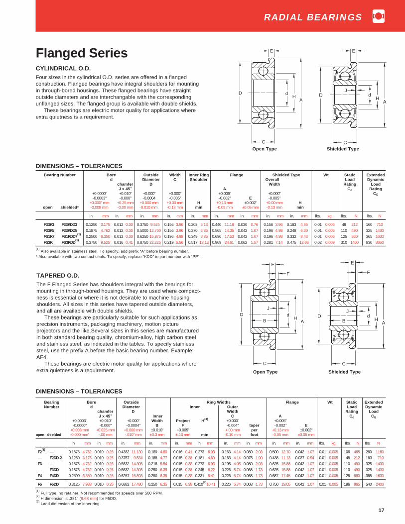
17
Flanged SeriesCYLINDRICAL O.D.Four sizes in the cylindrical O.D. series are offered in a flangedconstruction. Flanged bearings have integral shoulders for mountingin through-bored housings. These flanged bearings have straightoutside diameters and are interchangable with the correspondingunflanged sizes. The flanged group is available with double shields.
These bearings are electric motor quality for applications whereextra quietness is a requirement.
DIMENSIONS – TOLERANCES Bearing Number Bore Outside Width Inner Ring Flange Shielded Type Wt Static Extended
d Diameter C Shoulder Overall Load Dynamicchamfer D Width Rating LoadJ x 45° A Co Rating
+0.0000" +0.010" +0.000" +0.000" +0.005" +0.000" CE-0.0003" -0.000" -0.0004 -0.005" -0.002" E -0.005"
+0.000" mm +0.25 mm +0.000 mm +0.00 mm H +0.13 mm ±0.002" +0.00 mm Hopen shielded* -0.008 mm -0.00 mm -0.010 mm. -0.13 mm min -0.05 mm ±0.05 mm -0.13 mm min
in. mm in. mm in. mm in. mm in. mm in. mm in. mm in. mm in. mm lbs. kg. lbs. N lbs. N
F33K3 F33KDD3 0.1250 3.175 0.012 0.30 0.3750 9.525 0.156 3.96 0.202 5.13 0.440 11.18 0.030 0.76 0.156 3.96 0.183 4.65 0.01 0.005 48 212 160 710F33K5 F33KDD5 0.1875 4.762 0.012 0.30 0.5000 12.700 0.156 3.96 0.270 6.86 0.565 14.35 0.042 1.07 0.196 4.98 0.248 6.30 0.01 0.005 110 490 325 1430FS1K7 FS1KDD7
(1)0.2500 6.350 0.012 0.30 0.6250 15.875 0.196 4.98 0.349 8.86 0.690 17.53 0.042 1.07 0.196 4.98 0.332 8.43 0.01 0.005 125 560 365 1630
FS3K FS3KDD(1)
0.3750 9.525 0.016 0.41 0.8750 22.225 0.219 5.56 0.517 13.13 0.969 24.61 0.062 1.57 0.281 7.14 0.475 12.06 0.02 0.009 310 1400 830 3650
(1) Also available in stainless steel. To specify, add prefix “A” before bearing number.
* Also available with two contact seals. To specify, replace “KDD” in part number with “PP”.
TAPERED O.D.The F Flanged Series has shoulders integral with the bearings formounting in through-bored housings. They are used where compact-ness is essential or where it is not desirable to machine housingshoulders. All sizes in this series have tapered outside diameters,and all are available with double shields.
These bearings are particularly suitable for such applications asprecision instruments, packaging machinery, motion pictureprojectors and the like.Several sizes in this series are manufacturedin both standard bearing quality, chromium-alloy, high carbon steeland stainless steel, as indicated in the tables. To specify stainlesssteel, use the prefix A before the basic bearing number. Example:AF4.
These bearings are electric motor quality for applications whereextra quietness is a requirement.
dD H
A
E
C
JdD
HA
E
C
dD H
A
E
C
F
J
BdD
HA
E
C
J
F
B
Open Type Shielded Type
Open Type Shielded Type
DIMENSIONS – TOLERANCES
Bearing Bore Outside Ring Widths Flange Wt Static ExtendedNumber d Diameter Inner Outer Load Dynamic
chamfer D Width Rating LoadJ x 45° Inner C A C o CE
+0.0003" +0.010" +0.000" Width Project H (3) +0.000" +0.005"-0.0000" -0.000" -0.0004" B F -0.004" taper -0.002" E
+0.008 mm +0.025 mm +0.000 mm ±0.010" +0.005" +.00 mm per +0.13 mm ±0.002"open shielded -0.000 mm" -.00 mm -.010" mm ±0.3 mm ±.13 mm min -0.10 mm foot -0.05 mm ±0.05 mm
in. mm in. mm in. mm in. mm in. mm in. mm in. mm in. mm in. mm in. mm lbs. kg. lbs. N lbs. N
F2(1)
— 0.1875 4.762 0.010 0.25 0.4382 11.130 0.189 4.80 0.016 0.41 0.273 6.93 0.163 4.14 0.080 2.03 0.500 12.70 0.042 1.07 0.01 0.005 106 465 260 1160— F2DD-2 0.1250 3.175 0.010 0.25 0.3757 9.534 0.188 4.77 0.015 0.38 0.181 4.60 0.163 4.14 0.075 1.90 0.438 11.13 0.037 0.94 0.01 0.005 48 212 160 710F3 — 0.1875 4.762 0.010 0.25 0.5632 14.305 0.218 5.54 0.015 0.38 0.273 6.93 0.195 4.95 0.080 2.03 0.625 15.88 0.042 1.07 0.01 0.005 110 490 325 1430— F3DD 0.1875 4.762 0.010 0.25 0.5632 14.305 0.250 6.35 0.015 0.38 0.245 6.22 0.226 5.74 0.068 1.73 0.625 15.88 0.042 1.07 0.01 0.005 110 490 325 1430F4 F4DD 0.2500 6.350 0.010 0.25 0.6257 15.893 0.250 6.35 0.015 0.38 0.331 8.41 0.226 5.74 0.068 1.73 0.687 17.45 0.042 1.07 0.01 0.005 125 560 365 1630
F5 F5DD 0.3125 7.938 0.010 0.25 0.6882 17.480 0.250 6.35 0.015 0.38 0.410(2)
10.41 0.226 5.74 0.068 1.73 0.750 19.05 0.042 1.07 0.01 0.005 196 865 540 2400
(1) Full type, no retainer. Not recommended for speeds over 500 RPM.
(2) H dimension is .381" (9.68 mm) for F5DD.
(3) Land dimension of the inner ring.
RADIAL BEARINGS

18
ST Flangette UnitPressed steel housed units designed specifically for light duty applica-tions are available in shaft sizes from 1⁄4 to 1⁄2 inch. This unit is designedto simplify mounting on side plate or frame type housings.
The unit consists of two identical steel stampings which house aclamp type bearing having a spherical O.D. outer ring. The sphericalinside surface of each stamping mates with the spherical O.D. of thebearing to provide initial self-alignment at mounting. In addition, this unitoffers the features of the basic clamp-type bearing. This series isavailable with sealed or shielded construction. Radial load capacity ofthe unit is 25% of the basic bearing’s dynamic load rating at 33.3 R.P.M.
Bearings inspected to ABEC-1 tolerances except bore.Recommended shaft tolerance: Nominal bore size to -.0005"
resulting in .000" to .001" loose shaft fit.
Unit Bore** Set Max.Number d A d 1 H2 M G A1 H L J N Screw Radial
+0.0005" Thread* Unit-0.0000" Load+0.13 mm-0.000 mm
in. mm in. mm in. mm in. mm in. mm in. mm in. mm in. mm in. mm in. mm in. mm lbs. N
S1PPB7-3 ST 0.2500 6.350 7⁄32 5.556 9⁄16 14.287 25⁄32 19.844 0.430 10.922 0.079 2.007 0.0269 0.683 125⁄32 45.244 7⁄8 22.225 17⁄32 30.956 7⁄32 0.219 4-40 70 312S3PPB15 ST 0.3125 7.937 9⁄32 7.144 25⁄32 19.844 1 3⁄32 27.781 0.562 14.275 0.107 2.718 0.0329 0.836 2 3⁄32 53.181 13⁄16 30.163 117⁄32 38.894 7⁄32 0.219 8-36 150 668S3PPB5 ST 0.3750 9.525 9⁄32 7.144 25⁄32 19.844 13⁄32 27.781 0.562 14.275 0.107 2.718 0.0329 0.836 2 3⁄32 53.181 13⁄16 30.163 117⁄32 38.894 7⁄32 0.219 8-36 150 668S5PPB2 ST 0.5000 12.700 5⁄16 7.937 29⁄32 23.019 19⁄32 32.544 0.625 15.875 0.120 3.048 0.0359 0.912 211⁄32 59.531 17⁄16 36.512 125⁄32 45.244 7⁄32 0.219 8-36 220 980
RTF-Rubber TireFlange Housed UnitA synthetic, conductive elastomer of Durometer hardness 80-85facilitates mounting of standard cylindrical O.D. bearings in side plate offrame type housings. A generous taper on the entrance corner of therubber cartridge simplifies insertion of the unit into the side panel andassures reasonable squareness of the bearings when fully mounted.The bearing is positioned by the integral flange of the rubber cartridge.Resiliency of the elastomer accomodates wider than standardrecommened housing bore tolerance; greater flexibility in adjusting tominor shaft and/or housing misalignment; and helps reduce airbornenoise and structural vibration. Additional advantages of the RTF seriesare those offered by the features of the basic clamp-type bearing design.Due to the deflection characteristics of the elastomer, the radial andthrust ratings for the RTF series is 10% of the basic bearings dynamicload rating at 33.3 R.P.M.
Bearings inspected to ABEC-1 tolerances except bore.Recommended shaft tolerance: Nominal bore size to -.0005"
resulting in .000" to .001" loose shaft fit.
Unit Bore** D Set Max.number d RTF HSG C d 1 E B G H Screw Radial
+0.0005" O.D. Bore Thread* Unit-0.0000" Load
+.013 mm ±.005 ±.005-.000 mm ±.13mm ±.13mm
in. mm in. mm in. mm in. mm in. mm in. mm in. mm in. mm in. mm lbs. N
S1PP73RTF 0.2500 6.350 0.762 19.355 0.750 19.050 17⁄32 13.494 9⁄16 14.287 7⁄8 22.225 15⁄32 11.906 5⁄64 1.984 19⁄64 7.541 4-40 26 116S3PP16RTF 0.3125 7.937 1.074 27.280 1.062 26.975 3⁄4 19.050 25⁄32 19.844 17⁄32 30.956 5⁄8 15.875 5⁄32 3.969 13⁄32 10.319 8-36 58 258S3PP4RTF 0.3750 9.525 1.074 27.280 1.062 26.975 3⁄4 19.050 25⁄32 19.844 17⁄32 30.956 5⁄8 15.875 5⁄32 3.969 13⁄32 10.319 8-36 58 258S5PP2RTF 0.5000 12.700 1.388 35.255 1.375 34.925 1 25.400 29⁄32 23.019 117⁄32 38.894 45⁄64 17.859 5⁄32 3.969 15⁄32 11.906 8-36 88 392
d
H MIN.
FRAME OPENING
A STOCK THICKNESS
G
M
d12
A
BOLT HOLE DIA. "N"2 HOLES - 180° APART
L
H J
SETSCREW
1
Dd
d
SETSCREW
C
1
B
H
G
E
* All setscrews are hex socket oval point, 6 fluted socket setscrews available upon request. ** Bore tolerance applies prior to collar assembly.Setscrews with fused plastic patch available at added cost.
* All setscrews are hex socket oval point, 6 fluted socket setscrews available upon request. Setscrews with fused ** Bore tolerance applies prior to collar assembly.plastic patch available at added cost.
RADIAL BEARINGS

19
Special BearingsPulley, guide roller and pinch roll bearings are available in severalbore sizes providing the advantages of light weight, low inertia, lowtorque, and accurate running characteristics with minimum runoutand wobble. Many of these units feature outer ring assemblies withintegral molded “tires”. The most commonly used tire materials arealuminum, steel, and a variety of engineered plastics such as nylon,polycarbonate, acetal resin, or polyurethane. The tire material andconfiguration are determined by the particular application require-ments. Standard materials and shapes can be made available inmany sizes; and, our Engineering Department is prerpared tocooperate in testing any material you feel is suitable for yourapplication.
Through Fafnir’s universal ring design, sealed or shieldedversions of the “special” are readily available with the most basicbearing sizes. Varying degrees of seal drag are offered to suit thesealing torque requirements dictated by the environmental conditionsof the application.
The integral assembly design concept offers a complete packageof bearings, housings, shaft, etc. assembled and ready to mount onthe machine. Units are custom designed to solve customer assemblyproblems, minimize inventory of multiple components, and makepurchasing’s job easier in that one vendor is required instead ofseveral, all these factors contributing to an overall cost savings.
The bearing units shown have been developed especially forbusiness machine applications.
1/2 ± 1/64
.334MIN.REF.
.2500
.2495 5/8 REF.
.2812
.2762
.657MAX. REF.
.7500
.7496
1.005.995
TO CLEAR .016RBOTH SIDES
S1KDD-RT
RADIAL BEARINGS

Radial and Angular Contact BearingsRadial Bearings
RADIAL BEARINGS
Nomenclature
Ultra-Light 9300K Series . . . . . . . . . . . . . . . . . . . . . . . 20
Extra-Light 9100K Series . . . . . . . . . . . . . . . . . . 20, 21
Light 200K Series . . . . . . . . . . . . . . . . . . . . . . . . 22, 23
Light 200W Series . . . . . . . . . . . . . . . . . . . . . . . . 24, 25
Light 200 Series, Extra Width Inner Ring . . . . . . 26, 27
Light 200 Series, Felt Seal Type . . . . . . . . . . . . . . . . . 28
Light, Wide Type, W200PP, W200KLL Series . . . . . . . 29
Medium 300K Series . . . . . . . . . . . . . . . . . . . . . . 30, 31
Medium 300W Series . . . . . . . . . . . . . . . . . . . . . . 32, 33
Medium, Wide Type, W300PP, W300KLL Series . . . . . 34
Extra Large 100 Series . . . . . . . . . . . . . . . . . . . . . . . . 46
Page

Radial BearingsPrefixes:
A stainless steelF flanged outer ringH snug fitJ extra loose internal fit
JJ extra extra loose internal fitL internal self-aligningM precision ABEC-3
2M angular-contact, ABEC-3, 15°3M angular-contact, ABEC-3, 25°
MM superprecision, ABEC-7tolerances
MV ABEC-7 modified2MM angular-contact, ABEC-7, 15°3MM angular-contact, ABEC-7, 25°
P loose fitR normal fitS extra-small inch-dimension
type (Aerolite)T tight fitV precision ABEC-5
W wide-type single row (same widthinner and outer)
WIR single row- wide inner only
Suffixes:C1, C2, C3, etc. (manufacturing code -
Fafnir use only)FT full ball complementK Conrad, non-filling slot typeW maximum capacity, filling slot type
WI angular contact, low-shoulder, outerWO angular contact, low-shoulder, innerWN angular contact, low-shoulder,
inner and outer
Bore Size (04 and up: multiplylast two numbers by 5 to getbore in millimeters)00 10mm01 12mm02 15mm03 17mm04 20mm05 25mm12 60mm20 100mm
Numbers: Basic Type SeriesS1, 3, 5, 7, etc., single row inch, extra small30 single row metric, extra small
100 single row, extra large200 single row, light300 single row, medium
5200 double row, light5300 double row, medium7200 single row, angular contact, light7300 single row, angular contact, medium7400 single row, angular contact, heavy9100 single row, extra-light9300 single row, ultra-lightXLS inch dimension, conrad type
Additional FeaturesB spherical outside diameter
BR cast bronze retainerD one shield
DD two shieldsG Wireloc (snap ring)L one Mechanical-Seal
LL two Mechani-sealsMBR machined bronze retainer
P one sealPP two seals
PP2, 3, 4, etc. Tri-Ply Seals if prefix letter is W(example W208PPB5)
R one land riding rubber sealRR two land riding rubber seals
S external self-aligningSMBR iron silicon bronze retainer
T one felt sealTT two felt seals
W 3 05 K LL
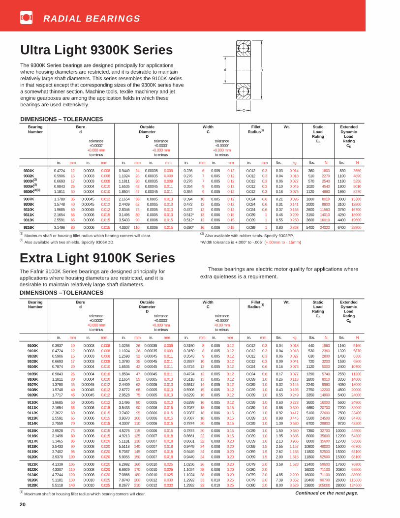
20
Ultra Light 9300K SeriesThe 9300K Series bearings are designed principally for applicationswhere housing diameters are restricted, and it is desirable to maintainrelatively large shaft diameters. This series resembles the 9100K seriesin that respect except that corresponding sizes of the 9300K series havea somewhat thinner section. Machine tools, textile machinery and jetengine gearboxes are among the application fields in which thesebearings are used extensively.
DIMENSIONS – TOLERANCES
These bearings are electric motor quality for applications whereextra quietness is a requirement.
DIMENSIONS –TOLERANCES
Bearing Bore Outside Width Fillet Wt. Static ExtendedNumber d Diameter C Radius
(1)Load Dynamic
D Rating Loadtolerance tolerance tolerance Co Rating+0.0000" +0.0000" +0.0000" CE
+0.000 mm +0.000 mm +0.00 mmto minus to minus to minus
in. mm in. mm in. mm in. mm in. mm in. mm in. mm lbs. kg lbs. N lbs. N
9100K 0.3937 10 0.0003 0.008 1.0236 26 0.00035 0.009 0.3150 8 0.005 0.12 0.012 0.3 0.04 0.018 440 1960 1160 51609101K 0.4724 12 0.0003 0.008 1.1024 28 0.00035 0.009 0.3150 8 0.005 0.12 0.012 0.3 0.04 0.018 530 2360 1320 58709102K 0.5906 15 0.0003 0.008 1.2598 32 0.00045 0.011 0.3543 9 0.005 0.12 0.012 0.3 0.06 0.027 630 2800 1430 63609103K 0.6693 17 0.0003 0.008 1.3780 35 0.00045 0.011 0.3937 10 0.005 0.12 0.012 0.3 0.09 0.041 720 3200 1530 68009104K 0.7874 20 0.0004 0.010 1.6535 42 0.00045 0.011 0.4724 12 0.005 0.12 0.024 0.6 0.16 0.073 1120 5000 2400 10700
9105K 0.9843 25 0.0004 0.010 1.8504 47 0.00045 0.011 0.4724 12 0.005 0.12 0.024 0.6 0.17 0.077 1290 5740 2550 113009106K 1.1811 30 0.0004 0.010 2.1654 55 0.0005 0.013 0.5118 13 0.005 0.12 0.039 1.0 0.26 0.118 1800 8010 3350 146009107K 1.3780 35 0.00045 0.012 2.4409 62 0.0005 0.013 0.5512 14 0.005 0.12 0.039 1.0 0.32 0.145 2240 9960 4050 180009108K 1.5748 40 0.00045 0.012 2.6772 68 0.0005 0.013 0.5906 15 0.005 0.12 0.039 1.0 0.43 0.195 2750 12200 4500 200009109K 1.7717 45 0.00045 0.012 2.9528 75 0.0005 0.013 0.6299 16 0.005 0.12 0.039 1.0 0.55 0.249 3350 14900 5400 24000
9110K 1.9685 50 0.00045 0.012 3.1496 80 0.0005 0.013 0.6299 16 0.005 0.12 0.039 1.0 0.60 0.272 3600 16000 5600 249009111K 2.1654 55 0.0006 0.015 3.5433 90 0.0006 0.015 0.7087 18 0.006 0.15 0.039 1.0 0.86 0.390 4650 20700 7200 320009112K 2.3622 60 0.0006 0.015 3.7402 95 0.0006 0.015 0.7087 18 0.006 0.15 0.039 1.0 0.92 0.417 5100 22600 7500 334009113K 2.5591 65 0.0006 0.015 3.9370 100 0.0006 0.015 0.7087 18 0.006 0.15 0.039 1.0 0.98 0.445 5500 24500 7800 347009114K 2.7559 70 0.0006 0.015 4.3307 110 0.0006 0.015 0.7874 20 0.006 0.15 0.039 1.0 1.39 0.630 6700 29800 9720 43200
9115K 2.9528 75 0.0006 0.015 4.5276 115 0.0006 0.015 0.7874 20 0.006 0.15 0.039 1.0 1.50 0.680 7350 32700 10000 445009116K 3.1496 80 0.0006 0.015 4.9213 125 0.0007 0.018 0.8661 22 0.006 0.15 0.039 1.0 1.95 0.885 8000 35600 12200 543009117K 3.3465 85 0.0008 0.020 5.1181 130 0.0007 0.018 0.8661 22 0.008 0.20 0.039 1.0 2.13 0.966 8000 35600 12700 565009118K 3.5433 90 0.0008 0.020 5.5118 140 0.0007 0.018 0.9449 24 0.008 0.20 0.059 1.5 2.55 1.157 10800 48000 15000 667009119K 3.7402 95 0.0008 0.020 5.7087 145 0.0007 0.018 0.9449 24 0.008 0.20 0.059 1.5 2.62 1.188 11800 52500 15300 681009120K 3.9370 100 0.0008 0.020 5.9055 150 0.0007 0.018 0.9449 24 0.008 0.20 0.059 1.5 2.90 1.315 11800 52500 15300 68100
9121K 4.1339 105 0.0008 0.020 6.2992 160 0.0010 0.025 1.0236 26 0.008 0.20 0.079 2.0 3.59 1.628 13400 59600 17600 769009122K 4.3307 110 0.0008 0.020 6.6929 170 0.0010 0.025 1.1024 28 0.008 0.20 0.080 2.0 — — 16000 71100 20800 925009124K 4.7244 120 0.0008 0.020 7.0866 180 0.0010 0.025 1.1024 28 0.008 0.20 0.079 2.0 4.85 2.200 16000 71100 20000 889009126K 5.1181 130 0.0010 0.025 7.8740 200 0.0012 0.030 1.2992 33 0.010 0.25 0.079 2.0 7.39 3.352 20400 90700 26000 1156009128K 5.5118 140 0.0010 0.025 8.2677 210 0.0012 0.030 1.2992 33 0.010 0.25 0.080 2.0 8.00 3.629 23600 105000 28000 124500
(1) Maximum shaft or housing fillet radius which bearing corners will clear.
D
C
d
Bearing Bore Outside Width Fillet Wt. Static ExtendedNumber d Diameter C Radius (1) Load Dynamic
D Rating Loadtolerance tolerance tolerance Co Rating+0.0000" +0.0000" +0.0000" CE
+0.000 mm +0.000 mm +0.000 mmto minus to minus to minus
in. mm in. mm in. mm in. mm in. mm in. mm in. mm lbs. kg lbs. N lbs. N
9301K 0.4724 12 0.0003 0.008 0.9449 24 0.00035 0.009 0.236 6 0.005 0.12 0.012 0.3 0.03 0.014 360 1600 830 36509302K 0.5906 15 0.0003 0.008 1.1024 28 0.00035 0.009 0.276 7 0.005 0.12 0.012 0.3 0.04 0.018 510 2270 1100 48909303K(2) 0.6693 17 0.0003 0.008 1.1811 30 0.00035 0.009 0.276 7 0.005 0.12 0.012 0.3 0.06 0.027 570 2540 1180 52509305K(2) 0.9843 25 0.0004 0.010 1.6535 42 0.00045 0.011 0.354 9 0.005 0.12 0.012 0.3 0.10 0.045 1020 4540 1800 80109306K(2)(3) 1.1811 30 0.0004 0.010 1.8504 47 0.00045 0.011 0.354 9 0.005 0.12 0.012 0.3 0.16 0.075 1120 4980 1860 8270
9307K 1.3780 35 0.00045 0.012 2.1654 55 0.0005 0.013 0.394 10 0.005 0.12 0.024 0.6 0.21 0.095 1800 8010 3000 133009308K 1.5748 40 0.00045 0.012 2.4409 62 0.0005 0.013 0.472 12 0.005 0.12 0.024 0.6 0.31 0.141 2000 8900 3100 138009310K 1.9685 50 0.00045 0.012 2.8346 72 0.0005 0.013 0.472 12 0.005 0.12 0.024 0.6 0.37 0.168 2600 11560 3750 167009311K 2.1654 55 0.0006 0.015 3.1496 80 0.0005 0.013 0.512* 13 0.006 0.15 0.039 1 0.46 0.209 3150 14010 4250 189009313K 2.5591 65 0.0006 0.015 3.5433 90 0.0006 0.015 0.512* 13 0.006 0.15 0.039 1 0.55 0.250 3600 16010 4400 19600
9316K 3.1496 80 0.0006 0.015 4.3307 110 0.0006 0.015 0.630* 16 0.006 0.15 0.039 1 0.80 0.363 5400 24020 6400 28500(1)
Maximum shaft or housing fillet radius which bearing corners will clear.(2)
Also available with rubber seals. Specify 9303PP.(3)
Also available with two shields. Specify 9306KDD. *Width tolerance is +.000" to -.006" (+.00mm to -.15mm)
Continued on the next page.
Extra Light 9100K SeriesThe Fafnir 9100K Series bearings are designed principally forapplications where housing diameters are restricted, and it isdesirable to maintain relatively large shaft diameters.
RADIAL BEARINGS

21
Bearing Bore Outside Width Fillet Wt. Static ExtendedNumber d Diameter C Radius
(1)Load Dynamic
D Rating Loadtolerance tolerance tolerance Co Rating+0.0000" +0.0000" +0.000" Ce
+0.000 mm +0.000 mm +0.00 mmto minus to minus to minus
in. mm in. mm in. mm in. mm in. mm in. mm in. mm lbs. kg lbs. N lbs. N
9130K 5.9055 150 0.0010 0.025 8.8583 225 0.0012 0.030 1.3780 35 0.010 0.25 0.08 2.0 12.0 5.5 20800 92500 25500 1134009132K 6.2992 160 0.0010 0.025 9.4488 240 0.0012 0.030 1.4961 38 0.010 0.25 0.08 2.0 14.8 6.7 31000 138000 37500 1668009134K 6.6929 170 0.0010 0.025 10.2362 260 0.0014 0.035 1.6535 42 0.010 0.25 0.08 2.0 19.8 9.0 36000 160000 42500 1890009136K 7.0866 180 0.0010 0.025 11.0236 280 0.0014 0.035 1.8110 44 0.010 0.25 0.08 2.0 24.3 11.0 44000 195700 50000 2220009138K 7.4803 190 0.0012 0.030 11.4173 290 0.0014 0.035 1.8110 46 0.012 0.30 0.08 2.0 26.5 12.0 45500 204000 48000 216000
9140K 7.8740 200 0.0012 0.030 12.2047 310 0.0014 0.035 2.0079 51 0.012 0.30 0.08 2.0 34.0 15.4 55000 245000 55000 2450009144K 8.6614 220 0.0012 0.030 13.3858 340 0.0016 0.040 2.2047 56 0.012 0.30 0.10 2.5 44.2 20.0 65500 290000 63000 2800009146K 9.4488 240 0.0012 0.030 14.1732 360 0.0016 0.040 2.2047 56 0.012 0.30 0.10 2.5 47.3 21.5 72000 320000 65500 2900009152K 10.2362 260 0.0014 0.035 15.7480 400 0.0016 0.040 2.5591 65 0.014 0.35 0.12 3.0 69.6 31.6 90000 400000 78000 3450009156K 11.0236 280 0.0014 0.035 16.5354 420 0.0018 0.045 2.5591 65 0.014 0.35 0.12 3.0 73.8 33.5 80000 355000 80000 360000
9160K 11.8110 300 0.0014 0.035 18.1102 460 0.0018 0.045 2.9134 74 0.014 0.35 0.12 3.0 102.9 46.6 118000 520000 93000 4150009164K 12.5984 320 0.0016 0.040 18.8976 480 0.0018 0.045 2.9134 74 0.016 0.40 0.12 3.0 108.3 49.1 127000 570000 98000 4300009180K 15.7480 400 0.0016 0.040 23.6220 600 0.0020 0.050 3.5433 90 0.016 0.40 0.16 4.0 — — 180000 815000 122000 5500009100K/600 23.6220 600 0.0020 0.050 34.2520 870 0.0039 0.100 4.6457 118 0.020 0.50 0.20 5.0 — — 340000 1539000 180000 800000
(1) Maximum shaft or housing fillet radius which bearing corners will clear.
Extra Light 9100K Series(continued)
SHIELDS, SEALS AND SNAP RING COMBINATIONSShields and Seals Snap Ring (Wireloc)
(1)
One Two One Two One Shield Open Two TwoShield Shields Seal Seals And Seal Type Shields Seals
D DD P PP PD G DDG PPG O.D. Thickness Offset
in mm in mm in mm
9100KD 9100KDD 9100P 9100PP 9100PD — — — — — — — — —9101KD 9101KDD 9101P 9101PP 9101PD — — — — — — — — —9102KD 9102KDD 9102P 9102PP — 9102KG 9102KDDG 9102PPG 1 7⁄16 36.5 0.042 1.07 0.120 3.059103KD 9103KDD 9103P 9103PP 9103PD2
(2)9103KG 9103KDDG 9103PPG 1 35⁄64 39.3 0.042 1.07 0.120 3.05
9104KD 9104KDD 9104P 9104PP — 9104KG 9104KDDG 9104PPG 1 13⁄16 46.0 0.042 1.07 0.120 3.05
9105KD 9105KDD 9105P 9105PP — — — — 2 1⁄16 52.4 0.042 1.07 0.120 3.059106KD 9106KDD 9106P 9106PP 9106PD 9106KG 9106KDDG 9106PPG 2 3⁄8 60.3 0.042 1.07 0.120 3.059107KD 9107KDD 9107P 9107PP — 9107KG 9107KDDG 9107PPG 2 21⁄32 67.5 0.065 1.65 0.143 3.639108KD 9108KDD 9108P 9108PP — 9108KG 9108KDDG 9108PPG 2 59⁄64 74.2 0.065 1.65 0.159 4.049109KD 9109KDD 9109P 9109PP 9109PD 9109KG 9109KDDG 9109PPG 3 13⁄64 81.4 0.065 1.65 0.159 4.04
9110KD 9110KDD 9110P 9110PP — 9110KG — — 3 13⁄32 86.5 0.065 1.65 0.159 4.049111KD 9111KDD 9111P 9111PP — 9111KG — 9111PPG 3 51⁄64 96.4 0.095 2.41 0.204 5.189112KD 9112KDD 9112P 9112PP — 9112KG — — 3 63⁄64 101.2 0.095 2.41 0.204 5.189113KD 9113KDD 9113P 9113PP 9113PD 9113KG — 9113PPG 4 3⁄16 106.4 0.095 2.41 0.204 5.189114KD 9114KDD 9114P 9114PP — 9114KG — — 4 37⁄64 116.3 0.095 2.41 0.204 5.18
9115KD 9115KDD 9115P 9115PP — — — — 4 25⁄32 121.4 0.095 2.41 0.204 5.18— — — — — — — — — — — — — —
9117KD — — — — 9117KG 9117KDDG — 5 1⁄2 139.7 0.109 2.77 0.218 5.54— — — — — — — — — — — — — —— — — — — — — — — — — — — —
9120KD — — 9120NPP — — — — 6 9⁄32 159.5 0.109 2.77 0.250 6.35
9121KD — — — — — — — 6 43⁄64 169.5 0.109 2.77 0.250 6.35— — — — — — — — — — — — — —
9124KD — 9124P 9124PP — 9124KG — — 7 19⁄32 192.9 0.120 3.05 0.261 6.63— — — — — — — — — — — — — —— — — — — — — — — — — — — —
(1) The snap ring is normally packaged separately in the box with bearing.
(2) Width of bearing is .5000" (12.700mm)
D
C
d
RADIAL BEARINGS
DIMENSIONS – TOLERANCES
OFFSET
THICKNESS
O.D.

22
Light 200K SeriesThe light 200K Series, Conrad-type bearing is well balanced withdeep races and uninterrupted race shoulders. Being an excellent,general purpose bearing, it has the capacity to carry radial, thrust ineither direction or combined loads.
These bearings are electric motor quality for applications whereextra quietness is a requirement.
Bearing Bore Outside Width Fillet Wt. Static ExtendedNumber d Diameter C Radius
(1)Load Dynamic
D Rating Loadtolerance tolerance tolerance Co Rating+0.0000" +0.0000" +0.000" CE
+0.000 mm +0.000 mm +0.00 mmto minus to minus to minus
in. mm in. mm in. mm in. mm in. mm in. mm in. mm lbs. kg lbs. N lbs. N
200K 0.3937 10 0.0003 0.008 1.1811 30 0.00035 0.009 0.3543 9 0.005 0.12 0.024 0.6 0.06 0.027 585 2600 1530 6800201K 0.4724 12 0.0003 0.008 1.2598 32 0.00045 0.011 0.3937 10 0.005 0.12 0.024 0.6 0.08 0.036 680 3000 1730 7600202K 0.5906 15 0.0003 0.008 1.3780 35 0.00045 0.011 0.4331 11 0.005 0.12 0.024 0.6 0.09 0.041 830 3470 1930 8650203K 0.6693 17 0.0003 0.008 1.5748 40 0.00045 0.011 0.4724 12 0.005 0.12 0.024 0.6 0.14 0.064 1060 4700 2450 10900204K 0.7874 20 0.0004 0.010 1.8504 47 0.00045 0.011 0.5512 14 0.005 0.12 0.039 1.0 0.23 0.104 1460 6500 3250 14400
205K 0.9843 25 0.0004 0.010 2.0472 52 0.0005 0.013 0.5906 15 0.005 0.12 0.039 1.0 0.28 0.127 1760 7800 3600 16000206K 1.1811 30 0.0004 0.010 2.4409 62 0.0005 0.013 0.6299 16 0.005 0.12 0.039 1.0 0.43 0.195 2550 11300 5000 22200207K 1.3780 35 0.00045 0.012 2.8346 72 0.0005 0.013 0.6693 17 0.005 0.12 0.039 1.0 0.64 0.29 3450 15300 6550 29100208K 1.5748 40 0.00045 0.012 3.1496 80 0.0005 0.013 0.7087 18 0.005 0.12 0.039 1.0 0.83 0.376 4500 20000 8300 36900209K 1.7717 45 0.00045 0.012 3.3465 85 0.0006 0.015 0.7480 19 0.005 0.12 0.039 1.0 0.94 0.426 4550 20200 8300 36900
210K 1.9685 50 0.00045 0.012 3.5433 90 0.0006 0.015 0.7874 20 0.005 0.12 0.039 1.0 1.05 0.476 5200 23100 9000 40000211K 2.1654 55 0.0006 0.015 3.9370 100 0.0006 0.015 0.8268 21 0.006 0.15 0.059 1.5 1.4 0.635 6550 29100 11000 49000212K 2.3622 60 0.0006 0.015 4.3307 110 0.0006 0.015 0.8661 22 0.006 0.15 0.059 1.5 1.78 0.807 8000 35500 13400 60000213K 2.5591 65 0.0006 0.015 4.7244 120 0.0006 0.015 0.9055 23 0.006 0.15 0.059 1.5 2.24 1.016 9000 39900 14600 65000214K 2.7559 70 0.0006 0.015 4.9213 125 0.0007 0.018 0.9449 24 0.006 0.15 0.059 1.5 2.44 1.107 9800 43500 16000 71100
215K 2.9528 75 0.0006 0.015 5.1181 130 0.0007 0.018 0.9843 25 0.006 0.15 0.059 1.5 2.64 1.198 10000 44400 16000 71100216K 3.1496 80 0.0006 0.015 5.5118 140 0.0007 0.018 1.0236 26 0.006 0.15 0.079 2.0 3.27 1.483 12200 54200 18300 81300217K 3.3465 85 0.0008 0.020 5.9055 150 0.0007 0.018 1.1024 28 0.008 0.20 0.079 2.0 4.10 1.86 14000 62200 21600 95900218K 3.5433 90 0.0008 0.020 6.2992 160 0.0010 0.025 1.1811 30 0.008 0.20 0.079 2.0 4.87 2.209 16000 71100 24500 109000
220K 3.9370 100 0.0008 0.020 7.0866 180 0.0010 0.025 1.3386 34 0.008 0.20 0.080 2.0 8.98 4.07 20800 93000 30500 134000221K 4.1339 105 0.0008 0.020 7.4803 190 0.0012 0.030 1.4173 36 0.008 0.20 0.080 2.0 8.32 3.77 20800 93000 28500 127000222K 4.3307 110 0.0008 0.020 7.8740 200 0.0012 0.030 1.4961 38 0.008 0.20 0.080 2.0 9.47 4.3 23600 104900 34500 153000224K 4.7244 120 0.0008 0.020 8.4646 215 0.0012 0.030 1.5748 40 0.008 0.20 0.080 2.0 15.56 7.06 30000 133000 39000 173000226K 5.1181 130 0.0010 0.020 9.0551 230 0.0012 0.030 1.5748 40 0.010 0.25 0.120 3.0 14.63 6.64 33500 149000 42500 189000228K 5.5118 140 0.0010 0.025 9.8425 250 0.0012 0.030 1.6535 42 0.010 0.25 0.120 3.0 24.66 11.19 36500 162000 45000 200000
230K 5.9055 150 0.0010 0.025 10.6299 270 0.0014 0.035 1.7717 45 0.010 0.25 0.120 3.0 26.8 12.1 40500 180000 49000 218000232K 6.2992 160 0.0010 0.025 11.4173 290 0.0014 0.035 1.8898 48 0.010 0.25 0.120 3.0 33.1 15.0 53000 235000 58500 260000234K 6.6929 170 0.0010 0.025 12.2047 310 0.0014 0.035 2.0472 52 0.010 0.25 0.160 4.0 41.1 18.7 62000 276000 65500 291000236K 7.0866 180 0.0010 0.025 12.5984 320 0.0016 0.040 2.0472 52 0.010 0.25 0.160 4.0 42.7 19.4 67000 298000 69500 309000238K 7.4803 190 0.0012 0.030 13.3858 340 0.0016 0.040 2.1654 55 0.012 0.30 0.160 4.0 50.7 23.0 65000 290000 67000 300000
240K 7.8740 200 0.0012 0.030 14.1732 360 0.0016 0.040 2.2835 58 0.012 0.30 0.160 4.0 58.2 26.4 83000 375000 80000 355000242K 8.2677 210 0.0012 0.030 14.9606 380 0.0016 0.040 2.4016 61 0.012 0.30 0.160 4.0 71.4 32.4 76500 335000 73500 325000244K 8.6614 220 0.0012 0.030 15.7480 400 0.0016 0.040 2.5591 65 0.012 0.30 0.160 4.0 81.4 36.9 86500 380000 80000 355000246K 9.0551 230 0.0012 0.030 16.5354 420 0.0018 0.045 2.6772 68 0.012 0.30 0.160 4.0 93.3 44.6 95000 425000 85000 380000248K 9.4488 240 0.0012 0.030 17.3228 440 0.0018 0.045 2.8346 72 0.012 0.30 0.160 4.0 103.1 46.8 116000 520000 102000 455000
250K 9.8425 250 0.0014 0.035 18.1102 460 0.0018 0.045 2.9921 76 0.012 0.30 0.160 4.0 122.4 55.5 129000 585000 110000 490000252K 10.2362 260 0.0014 0.035 18.8976 480 0.0018 0.045 3.1496 80 0.014 0.35 0.200 5.0 139.0 63.0 143000 640000 118000 520000256K 11.0236 280 0.0014 0.035 19.6850 500 0.0018 0.045 3.1496 80 0.014 0.35 0.200 5.0 141.4 64.1 160000 710000 125000 560000260K 11.8110 300 0.0014 0.035 21.2598 540 0.0020 0.050 3.3465 85 0.014 0.35 0.200 5.0 192.7 87.4 150000 670000 116000 520000264K 12.5984 320 0.0016 0.040 22.8346 580 0.0020 0.050 3.6220 92 0.016 0.40 0.200 5.0 208.5 94.6 220000 980000 160000 710000
(1) Maximum shaft or housing fillet radius which bearing corners will clear.
D
C
d
RADIAL BEARINGS
DIMENSIONS – TOLERANCES
23
SHIELDS, SEALS AND SNAP RING COMBINATIONSShields and Seals Snap Ring (Wireloc)
One Two One One Seal Two (3) Open One One Two One Two One SealShield Shields Seal One Shield Seals Type Shield Shield Shields Seal Seals One Shield O.D. Thickness Offset D DD (N) P PD (N) PP G DG GD DDG PG PPG PDG Snap Ring
in. mm in. mm in. mm
200KD 200KDD 200P 200PD(2)
200PP — — — 200KDDG — 200PPG — 123⁄64 34.5 0.042 1.07 0.120 3.05201KD 201KDD 201P 201PD 201PP 201KG 201KDG — 201KDDG — 201PPG — 17⁄16 36.5 0.042 1.07 0.120 3.05202KD 202KDD 202P 202PD 202PP 202KG 202KDG — 202KDDG — 202PPG — 135⁄64 39.3 0.042 1.07 0.120 3.05203KD 203KDD 203P 203PD 203PP 203KG 203KDG — 203KDDG — 203PPG — 13⁄4 44.4 0.042 1.07 0.120 3.05204KD 204KDD 204P 204PD 204PP 204KG 204KDG — 204KDDG — 204PPG — 21⁄16 52.4 0.042 1.07 0.136 3.45
205KD 205KDD 205P 205PD 205PP 205KG 205KDG — 205KDDG — 205PPG — 217⁄64 57.5 0.042 1.07 0.136 3.45206KD 206KDD 206P 206PD 206PP 206KG 206KDG — 206KDDG — 206PPG — 221⁄32 67.6 0.065 1.65 0.190 4.83207KD 207KDD 207P 207PD 207PP 207KG 207KDG — 207KDDG — 207PPG — 35⁄64 78.2 0.065 1.65 0.190 4.83208KD 208KDD 208P — 208PP 208KG 208KDG — 208KDDG — 208PPG — 313⁄32 86.5 0.065 1.65 0.190 4.83209KD 209KDD 209P — 209PP 209KG 209KDG — 209KDDG — — — 319⁄32 91.3 0.065 1.65 0.190 4.83
210KD 210KDD 210P — 210PP 210KG 210KDG — 210KDDG — 210NPPG — 351⁄64 96.4 0.095 2.41 0.220 5.59211KD 211KDD 211NP 211NPD 211NPP 211KG 211KDG 211KGD 211KDDG — 211NPPG 211NPDG 43⁄16 106.3 0.095 2.41 0.220 5.59212KD 212KDD 212NP 212NPD 212NPP 212KG 212KDG — — — 212NPPG 212NPDG 437⁄64 116.3 0.095 2.41 0.220 5.59213KD 213KDD 213NP — 213NPP 213KG — — 213KDDG — 213NPPG 213NPDG 53⁄32 129.4 0.109 2.77 0.265 6.73214KD 214KDD 214P — 214NPP 214KG 214KDG — — — — — 519⁄64 134.5 0.109 2.77 0.265 6.73
215KD 215KDD 215P — 215NPP — — — — — — — — — — — — —216KD 216KDD — — 216NPP — — — — — — — — — — — — —217KD 217KDD — — — — — — — — — — — — — — — —218KD 218KDD — — — — — — — — — — — — — — — —
— — — — — — — — — — — — — — — — — —— — — — — — — — — — — — — — — — — —222KD — — — — — — — — — — — — — — — — —
(1) The snap ring is normally packaged separately in the box with the bearing.
(2) Available with snap ring as 200PDG.
Note: “N” prefix for NP(P) seals indicate non-removable seal.
OFFSET
THICKNESS
O.D.
RADIAL BEARINGS
(3) Also available in"VV" sealed design, check on availability.

24
Light 200W SeriesThe 200W Series, maximum capacity type is dimensionally interchange-able with the 200K type but has greater capacity for supporting heavierradial loads and light thrust loads in either direction. Maximum capacitybearings feature a filling slot in the shoulder of each raceway toassemble an extra large ball complement. Consult The TorringtonCompany for the availability of sizes other than those listed here.
DIMENSIONS – TOLERANCESBearing Bore Outside Width Fillet Wt. Static ExtendedNumber d Diameter C Radius
(1)Load Dynamic
D Rating Loadtolerance tolerance tolerance CO Rating*+0.0000" +0.0000" +0.000" CE
+0.000mm +0.000mm +0.00mmto minus to minus to minus
in. mm in. mm in. mm in. mm in. mm in. mm in. mm lbs. kg lbs. N lbs. N
202W 0.5906 15 0.0003 0.008 1.3780 35 0.00045 0.011 0.4331 11 0.005 0.12 0.024 0.6 0.12 0.054 1140 5060 2450 11000204W(2) 0.7874 20 0.0004 0.010 1.8504 47 0.00045 0.011 0.5512 14 0.005 0.12 0.039 1.0 0.25 0.113 2120 9300 4400 19500205W(2) 0.9843 25 0.0004 0.010 2.0472 52 0.0005 0.013 0.5906 15 0.005 0.12 0.039 1.0 0.31 0.141 2750 12200 5100 22600206W 1.1811 30 0.0004 0.010 2.4409 62 0.0005 0.013 0.6299 16 0.005 0.12 0.039 1.0 0.47 0.213 3800 16900 6950 31000207W 1.3780 35 0.00045 0.012 2.8346 72 0.0005 0.013 0.6693 17 0.005 0.12 0.039 1.0 0.69 0.313 5100 22600 9000 40000
208W 1.5748 40 0.00045 0.012 3.1496 80 0.0005 0.013 0.7087 18 0.005 0.12 0.039 1.0 0.91 0.413 6400 28400 10600 47000209W 1.7717 45 0.00045 0.012 3.3465 85 0.0006 0.015 0.7480 19 0.005 0.12 0.039 1.0 1.02 0.463 7100 31500 11200 50000210W 1.9685 50 0.00045 0.012 3.5433 90 0.0006 0.015 0.7874 20 0.005 0.12 0.039 1.0 1.15 0.522 7800 34600 11800 52000211W 2.1654 55 0.0006 0.015 3.9370 100 0.0006 0.015 0.8268 21 0.006 0.15 0.059 1.5 1.50 0.68 9150 40600 13700 61000212W 2.3622 60 0.0006 0.015 4.3307 110 0.0006 0.015 0.8661 22 0.006 0.15 0.059 1.5 1.95 0.885 12200 54200 17600 78000
213W 2.5591 65 0.0006 0.015 4.7244 120 0.0006 0.015 0.9055 23 0.006 0.15 0.059 1.5 2.66 1.207 14600 64800 20800 92000214W 2.7559 70 0.0006 0.015 4.9213 125 0.0007 0.018 0.9449 24 0.006 0.15 0.059 1.5 2.70 1.225 16000 71100 21600 96000215W 2.9528 75 0.0006 0.015 5.1181 130 0.0007 0.018 0.9843 25 0.006 0.15 0.059 1.5 2.94 1.334 17000 75500 22400 99000216W 3.1496 80 0.0006 0.015 5.5118 140 0.0007 0.018 1.0236 26 0.006 0.15 0.079 2.0 3.60 1.633 20400 90600 26000 114000217W 3.3465 85 0.0008 0.020 5.9055 150 0.0007 0.018 1.1024 28 0.008 0.20 0.079 2.0 4.45 2.019 22400 96000 29000 129000
218W 3.5433 90 0.0008 0.020 6.2992 160 0.0010 0.025 1.1811 30 0.008 0.20 0.079 2.0 5.49 2.49 25500 96500 33500 149000219W 3.7402 95 0.0008 0.020 6.6929 170 0.0010 0.025 1.2598 32 0.008 0.20 0.079 2.0 6.70 3.039 29000 112000 38000 169000220W 3.9370 100 0.0008 0.020 7.0866 180 0.0010 0.025 1.3386 34 0.008 0.20 0.080 2.0 8.09 3.67 33500 127000 42500 188000221W 4.1339 105 0.0008 0.020 7.4803 190 0.0012 0.030 1.4173 36 0.008 0.20 0.080 2.0 9.43 4.277 35500 134000 44000 195000222W 4.3307 110 0.0008 0.020 7.8740 200 0.0012 0.030 1.4961 38 0.008 0.20 0.080 2.0 11.34 5.144 42500 160000 50000 222000
224W3 4.7244 120 0.0008 0.020 8.4646 215 0.0012 0.030 1.5748 40 0.010 0.25 0.080 2.0 14.52 6.586 41500 156000 50000 222000226W3 5.1181 130 0.0010 0.020 9.0551 230 0.0012 0.030 1.5748 40 0.010 0.25 0.120 3.0 16.80 7.62 53000 196000 58500 260000228W3 5.5118 140 0.0010 0.025 9.8425 250 0.0012 0.030 1.6535 42 0.010 0.25 0.120 3.0 20.50 9.3 58500 260000 61000 270000
230W 5.9055 150 0.0010 0.025 10.6299 270 0.0014 0.035 1.7717 45 0.010 0.25 0.120 3.0 27.50 12.5 65500 290000 67000 300000232W 6.2992 160 0.0010 0.025 11.4173 290 0.0014 0.035 1.8898 48 0.010 0.25 0.120 3.0 34.00 15.4 76500 340000 73500 325000234W 6.6929 170 0.0010 0.025 12.2047 310 0.0014 0.035 2.0472 52 0.010 0.25 0.160 4.0 42.00 19 85000 375000 78000 345000236W 7.0866 180 0.0010 0.025 12.5984 320 0.0016 0.040 2.0472 52 0.010 0.25 0.160 4.0 43.80 19.9 90000 405000 81500 365000238W 7.4803 190 0.0012 0.030 13.3858 340 0.0016 0.040 2.1654 55 0.012 0.30 0.160 4.0 52.00 23.6 104000 465000 91500 405000
240W 7.8740 200 0.0012 0.030 14.1732 360 0.0016 0.040 2.2835 58 0.012 0.30 0.160 4.0 59.80 27.1 125000 560000 106000 465000242W 8.2677 210 0.0012 0.030 14.9606 380 0.0016 0.040 2.4016 61 0.012 0.30 0.160 4.0 73.30 33.2 129000 570000 104000 465000244W 8.6614 220 0.0012 0.030 15.7480 400 0.0016 0.040 2.5591 65 0.012 0.30 0.160 4.0 83.90 38.1 153000 680000 120000 530000246W 9.0551 230 0.0012 0.030 16.5354 420 0.0018 0.045 2.6772 68 0.012 0.30 0.160 4.0 100.70 45.6 156000 695000 118000 530000248W 9.4488 240 0.0012 0.030 17.3228 440 0.0018 0.045 2.8346 72 0.012 0.30 0.160 4.0 107.40 48.7 193000 865000 143000 640000
250W 9.8425 250 0.0012 0.030 18.1102 460 0.0018 0.045 2.9921 76 0.012 0.30 0.160 4.0 126.80 57.5 208000 930000 150000 670000252W 10.2362 260 0.0014 0.035 18.8976 480 0.0018 0.045 3.1496 80 0.014 0.35 0.200 5.0 144.20 65.4 232000 1020000 160000 720000256W 11.0236 280 0.0014 0.035 19.6850 500 0.0018 0.045 3.1496 80 0.014 0.35 0.200 5.0 147.40 66.8 255000 1120000 170000 765000260W 11.8110 300 0.0014 0.035 21.2598 540 0.0020 0.050 3.3465 85 0.014 0.35 0.200 5.0 198.00 89.8 245000 1100000 160000 720000264W 12.5984 320 0.0016 0.040 22.8346 580 0.0020 0.050 3.6220 92 0.016 0.40 0.200 5.0 219.10 99.3 355000 1560000 216000 965000
(1) Maximum shaft or housing fillet radius which bearing corners will clear. *For applications where thrust load exceeds 60% of radial load consult The Torrington Company.(2) These sizes have molded nylon cages.
RADIAL BEARINGS
D
C
d
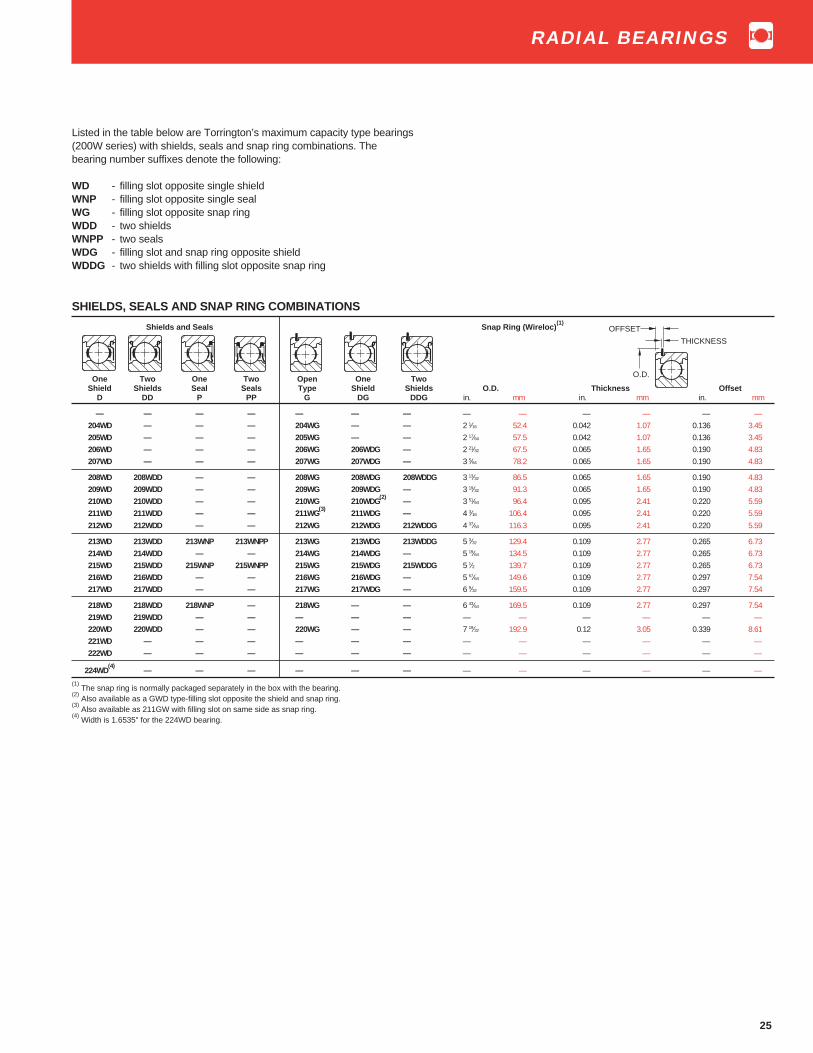
25
SHIELDS, SEALS AND SNAP RING COMBINATIONS
Shields and Seals Snap Ring (Wireloc)(1)
One Two One Two Open One TwoShield Shields Seal Seals Type Shield Shields O.D. Thickness Offset
D DD P PP G DG DDG in. mm in. mm in. mm
— — — — — — — — — — — — —204WD — — — 204WG — — 2 1⁄16 52.4 0.042 1.07 0.136 3.45205WD — — — 205WG — — 2 17⁄64 57.5 0.042 1.07 0.136 3.45206WD — — — 206WG 206WDG — 2 21⁄32 67.5 0.065 1.65 0.190 4.83207WD — — — 207WG 207WDG — 3 5⁄64 78.2 0.065 1.65 0.190 4.83
208WD 208WDD — — 208WG 208WDG 208WDDG 3 13⁄32 86.5 0.065 1.65 0.190 4.83209WD 209WDD — — 209WG 209WDG — 3 19⁄32 91.3 0.065 1.65 0.190 4.83210WD 210WDD — — 210WG 210WDG
(2)— 3 51⁄64 96.4 0.095 2.41 0.220 5.59
211WD 211WDD — — 211WG(3)
211WDG — 4 3⁄16 106.4 0.095 2.41 0.220 5.59212WD 212WDD — — 212WG 212WDG 212WDDG 4 37⁄64 116.3 0.095 2.41 0.220 5.59
213WD 213WDD 213WNP 213WNPP 213WG 213WDG 213WDDG 5 3⁄32 129.4 0.109 2.77 0.265 6.73214WD 214WDD — — 214WG 214WDG — 5 19⁄64 134.5 0.109 2.77 0.265 6.73215WD 215WDD 215WNP 215WNPP 215WG 215WDG 215WDDG 5 1⁄2 139.7 0.109 2.77 0.265 6.73216WD 216WDD — — 216WG 216WDG — 5 57⁄64 149.6 0.109 2.77 0.297 7.54217WD 217WDD — — 217WG 217WDG — 6 9⁄32 159.5 0.109 2.77 0.297 7.54
218WD 218WDD 218WNP — 218WG — — 6 43⁄64 169.5 0.109 2.77 0.297 7.54219WD 219WDD — — — — — — — — — — —220WD 220WDD — — 220WG — — 7 19⁄32 192.9 0.12 3.05 0.339 8.61221WD — — — — — — — — — — — —222WD — — — — — — — — — — — —
224WD(4)
— — — — — — — — — — — —
(1) The snap ring is normally packaged separately in the box with the bearing.
(2) Also available as a GWD type-filling slot opposite the shield and snap ring.
(3) Also available as 211GW with filling slot on same side as snap ring.
(4) Width is 1.6535" for the 224WD bearing.
Listed in the table below are Torrington’s maximum capacity type bearings(200W series) with shields, seals and snap ring combinations. Thebearing number suffixes denote the following:
WD - filling slot opposite single shieldWNP - filling slot opposite single sealWG - filling slot opposite snap ringWDD - two shieldsWNPP - two sealsWDG - filling slot and snap ring opposite shieldWDDG - two shields with filling slot opposite snap ring
OFFSET
THICKNESS
O.D.
RADIAL BEARINGS

26
DIMENSIONS – TOLERANCESBearing Number Bore Outside Diameter Ring Widths Fillet Wt Static Extended
d D +0.000,–.005" Radius(1)
Load Dynamictolerance tolerance +0.00,–.12 mm Rating Load
two two +0.0000" +0.0000" Co Ratingseals seals +0.000 mm +0.000 mm Inner Outer C E
LL NPP to minus to minus B2 C
in. mm in. mm in. mm in. mm in. mm in. mm in. mm lbs. kg. lbs. N lbs. N
200KLL2 200KRR3(4)
0.3937 10 0.0003 0.008 1.1811 30 0.00035 0.009 0.646 16.40 0.354 8.99 0.024 0.6 0.08 0.036 585 2650 1530 6800201KLL2 — 0.4724 12 0.0003 0.008 1.2598 32 0.00045 0.011 0.606 15.40 0.394 10.01 0.024 0.6 0.09 0.041 680 3000 1700 7500201KLL3 — 0.5118 13 0.0003 0.008 1.2598 32 0.00045 0.011 0.606 15.40 0.394 10.01 0.024 0.6 0.09 0.041 680 3000 1700 7500
202KLL2 — 0.5906 15 0.0003 0.008 1.3780 35 0.00045 0.011 0.567 14.40 0.433 11.00 0.024 0.6 0.10 0.045 830 3690 1930 8650202KLL3 202NPP11 0.6299 16 0.0003 0.008 1.3780 35 0.00045 0.011 0.567 14.40 0.433 11.00 0.024 0.6 0.10 0.045 830 3690 1930 8650203KLL2
(2)203NPP8 0.6693 17 0.0003 0.008 1.5748 40 0.00045 0.011 0.654 16.60 0.472 11.99 0.024 0.6 0.16 0.073 1060 4700 2450 10800
204KLL2 204NPP7 0.7874 20 0.0004 0.010 1.8504 47 0.00045 0.011 0.699 17.75 0.551 14.00 0.039 1.0 0.25 0.113 1460 6200 3200 14300205KLL2
(3)205NPP2 0.9843 25 0.0004 0.010 2.0472 52 0.0005 0.013 0.659 16.75 0.591 15.01 0.039 1.0 0.29 0.132 1760 7800 3600 16000
206KLL 206NPP2 1.1811 30 0.0004 0.010 2.4409 62 0.0005 0.013 0.945 24.00 0.630 16.00 0.039 1.0 0.51 0.231 2550 11300 5000 22200207KLL — 1.3780 35 0.00045 0.012 2.8346 72 0.0005 0.013 0.984 25.00 0.669 17.00 0.039 1.0 0.71 0.322 3450 15300 6550 29000208KLL — 1.5748 40 0.00045 0.012 3.1496 80 0.0005 0.013 1.188 30.18 0.709 18.01 0.039 1.0 1.02 0.463 4550 20200 8150 36000209KLL — 1.7717 45 0.00045 0.012 3.3465 85 0.0006 0.015 1.181 30.00 0.748 19.00 0.039 1.0 1.12 0.508 4550 20200 8300 37000
(1) Maximum shaft or housing fillet radius which bearing corners will clear.
(2) Also available as 203KLL with .718" (18.24mm) inner ring width.
(3) Also available as 205KLL with .812" (20.64mm) inner ring width.
(4) Equipped with “R” seals.
DIMENSIONS – TOLERANCES
Bearing Number Bore Outside Diameter Width Inner Ring Widths Fillet Wt. Static Extendedd D B1 Ring +0.000", –.005" Radius
(1)Load Dynamic
one seal tolerance tolerance Offset 0.00",–.12mm Rating Load one and +0.0000" +0.0000" Co Rating seal shield +0.000 mm +0.000 mm Inner Outer C E
L LD to minus to minus B C
in. mm in. mm in. mm in. mm in. mm in. mm in. mm in. mm in. mm lbs. kg. lbs. N lbs. N
200KL 200KLD 0.3937 10 0.0003 0.008 1.1811 30 0.00035 0.009 0.500 12.70 0.020 0.51 0.480 12.19 0.354 8.99 0.024 0.6 0.08 0.036 585 2650 1530 6550201KL 201KLD 0.4724 12 0.0003 0.008 1.2598 32 0.00045 0.011 0.500 12.70 0.020 0.51 0.480 12.19 0.394 10.01 0.024 0.6 0.09 0.041 680 3000 1730 7500— 201KLD2 0.5118 13 0.0003 0.008 1.2598 32 0.00045 0.011 0.500 12.70 0.020 0.51 0.480 12.19 0.394 10.01 0.024 0.6 0.09 0.041 680 3000 1730 7500201KL3 — 0.4358 11.07 0.0003 0.008 1.2598 32 0.00045 0.011 0.500 12.70 0.020 0.51 0.480 12.19 0.394 10.01 0.024 0.6 0.09 0.041 680 3000 1730 7500202KL4 202KLD4 0.5512 14 0.0003 0.008 1.3780 35 0.00045 0.011 0.500 12.70 0.020 0.51 0.480 12.19 0.433 11.00 0.024 0.6 0.10 0.045 830 3690 1930 8650
202KL 202KLD 0.5906 15 0.0003 0.008 1.3780 35 0.00045 0.011 0.500 12.70 0.020 0.51 0.480 12.19 0.433 11.00 0.024 0.6 0.10 0.045 830 3450 1930 8650202KL3 202KLD3 0.6299 16 0.0003 0.008 1.3780 35 0.00045 0.011 0.500 12.70 0.020 0.51 0.480 12.19 0.433 11.00 0.024 0.6 0.10 0.045 830 3450 1930 8650203KL 203KLD 0.6693 17 0.0003 0.008 1.5748 40 0.00045 0.011 0.563 14.30 0.025 0.64 0.538 13.67 0.472 11.99 0.024 0.6 0.16 0.073 1060 4700 2450 10800204KL 204KLD 0.7874 20 0.0004 0.010 1.8504 47 0.00045 0.011 0.625 15.88 0.025 0.64 0.600 15.24 0.551 14.00 0.039 1.0 0.25 0.113 1460 6200 3200 14300205KL 205KLD 0.9843 25 0.0004 0.010 2.0472 52 0.0005 0.013 0.625 15.88 0.025 0.64 0.600 15.24 0.591 15.01 0.039 1.0 0.29 0.132 1760 7800 3600 16000
206KL 206KLD 1.1811 30 0.0004 0.010 2.4409 62 0.0005 0.013 0.787 20.00 0.039 0.99 0.748 19.00 0.630 16.00 0.039 1.0 0.51 0.231 2550 10000 5000 22200207KL 207KLD 1.3780 35 0.00045 0.012 2.8346 72 0.0005 0.013 0.827 21.00 0.039 0.99 0.787 20.00 0.669 17.00 0.039 1.0 0.71 0.322 3450 13700 6550 29000209KL 209KLD 1.7717 45 0.00045 0.012 3.3465 85 0.0006 0.015 1.024 26.00 — — 1.024 26.00 0.748 19.00 0.039 1.0 1.12 0.508 4550 17600 8300 37000211KL 211KLD 2.1654 55 0.0006 0.015 3.9370 100 0.0006 0.015 1.063 27.00 — — 1.063 27.00 0.827 21.01 0.059 1.5 1.65 0.748 6550 29100 11000 49000
Light 200 SeriesExtra Width Inner RingThe 200 Series, extra width inner ring type has sizes available both in therubber seal (P) and Mechani-Seal (L) design.
A distinguishing feature of this series is the extra width inner ringwhich provides greater shaft support. The “P” seal version utilizes a BunaN rubber contact seal whereas the “L” seal employs a frictionless metallicmember to form a labyrinth.
These bearings are used extensively in high speed pneumatic tools,small pumps, electric motors, domestic appliances, etc.
These bearings are electric motor quality for applications where extraquietness is a requirement.
RADIAL BEARINGS

27
K
B
dD
C
E
B
1
K
B
C
E
B
1
K
B
C
P
2
d
B
C
2
D
One Mechani-Seal One Shield and Two Mechani-Seals Two Rubber SealsL Mechani-Seal LL NPP (2)
LD
MECHANI-SEAL SNAP RING COMBINATIONS
(Seal Projection) One One Two Snap Ring(1)
(L, LD, LL Types Only) Mechani-Seal Mechani-Seal Mechani-Sealsand Shield
Width O.D.E P K LG LDG LLG O.D. Thickness Offset
in. mm in. mm in. mm in. mm in. mm in. mm
0.481 12.22 0.613 15.57 1 25.4 — — 200KLLG2 1 23⁄64 34.5 0.042 1.07 0.120 3.050.480 12.19 0.567 14.40 1 1⁄16 27.0 — — 201KLLG2 1 7⁄16 36.5 0.042 1.07 0.120 3.050.480 12.19 0.567 14.40 1 1⁄16 27.0 — 201KLDG3 — 1 7⁄16 36.5 0.042 1.07 0.120 3.05
0.487 12.37 0.543 13.79 1 3⁄16 30.2 — 202KLDG 202KLLG2 1 35⁄64 39.3 0.042 1.07 0.120 3.050.487 12.37 0.543 13.79 1 3⁄16 30.2 — — 202KLLG3 1 35⁄64 39.3 0.042 1.07 0.120 3.050.551 14.00 0.630 16.00 1 3⁄8 34.9 203KLG — 203KLLG2 1 3⁄4 44.4 0.042 1.07 0.120 3.050.613 15.57 0.675 17.14 1 37⁄64 40.1 204KLG2 — 204KLLG2 2 1⁄16 52.4 0.042 1.07 0.136 3.450.613 15.57 0.635 16.13 1 51⁄64 45.6 205KLG2 — 205KLLG2 2 17⁄64 57.5 0.042 1.07 0.136 3.45
0.767 19.48 0.905 22.99 2 9⁄64 54.4 — — 206KLLG 2 21⁄32 67.5 0.065 1.65 0.190 4.830.807 20.50 0.944 23.98 2 15⁄32 62.7 — — 207KLLG 3 5⁄64 78.2 0.065 1.65 0.190 4.830.918 23.32 1.127 28.63 2 3⁄4 69.8 — — — 3 13⁄32 86.5 0.065 1.65 0.190 4.830.954 24.23 1.160 29.46 2 31⁄32 75.4 — — 209KLLG 3 19⁄32 91.3 0.065 1.65 0.190 4.83
(1) The snap ring is normally packaged separately in the box with the bearing.
(2) “N” prefix indicates a non-removable seal.
LG LDG LLG
OFFSET
THICKNESS
O.D.
RADIAL BEARINGS

28
Light 200 SeriesFelt Seal TypeThe felt seal type ball bearing permits certain design econo-mies, but cannot be assumed to be suitable for all conditionsof service. In many cases it is supplemented by other parts forreally adequate bearing protection in small equipment such asfractional horsepower motors, electric vacuum cleaners, smallgear units, electric and pneumatic tools, etc. Felt seal bearingsare recommended for effective grease retention and exclusionof foreign matter.
These bearings are electric motor quality for applicationswhere extra quietness is a requirement.
DIMENSIONS – TOLERANCES
Bearing Number Bore Outside Ring Widths Inner Fillet Wt. Static Extendedd Diameter 0.000",-.005" Ring Radius
(1)Load Dynamic
D 0.000",-.12 mm Offset Rating Loadone one seal tolerance tolerance CO Ratingseal and shield +0.0000" +0.0000" CE T TD +0.000 mm +0.000 mm inner outer
to minus to minus B C
in. mm in. mm in. mm in. mm in. mm in. mm in. mm in. mm lbs. kg lbs. N lbs. N
200KT 200KTD 0.3937 10 0.0003 0.008 1.1811 30 0.00035 0.009 0.480 12.19 0.500 12.70 0.020 0.51 0.024 0.6 0.10 0.045 585 2600 1530 6790— 200KTD2 0.4724 12 0.0003 0.008 1.1811 30 0.00035 0.009 0.480 12.19 0.500 12.70 0.020 0.51 0.024 0.6 0.10 0.045 585 2600 1530 6790201KT 201KTD 0.4724 12 0.0003 0.008 1.2598 32 0.00045 0.011 0.480 12.19 0.500 12.70 0.020 0.51 0.024 0.6 0.10 0.045 680 3000 1730 7680201KT2 201KTD2 0.5118 13 0.0003 0.008 1.2598 32 0.00045 0.011 0.480 12.19 0.500 12.70 0.020 0.51 0.024 0.6 0.10 0.045 680 3000 1730 7680202KT 202KTD 0.5906 15 0.0003 0.008 1.3780 35 0.00045 0.011 0.480 12.19 0.500 12.70 0.020 0.51 0.024 0.6 0.11 0.05 830 3600 1930 8650
202KT3(2)
202KTD3(2)
0.6299 16 0.0003 0.008 1.3780 35 0.00045 0.011 0.480 12.19 0.500 12.70 0.020 0.51 0.024 0.6 0.11 0.05 830 3600 1930 8650203KT 203KTD 0.6693 17 0.0003 0.008 1.5748 40 0.00045 0.011 0.538 13.67 0.563 14.30 0.025 0.64 0.024 0.6 0.17 0.077 1060 4700 2450 10900204KT 204KTD 0.7874 20 0.0004 0.010 1.8504 47 0.00045 0.011 0.600 15.24 0.625 15.88 0.025 0.64 0.039 1.0 0.26 0.118 1460 6500 3250 14400205KT 205KTD 0.9843 25 0.0004 0.010 2.0472 52 0.0005 0.013 0.600 15.24 0.625 15.88 0.025 0.64 0.039 1.0 0.29 0.132 1760 7800 3600 16000206KT 206KTD 1.1811 30 0.0004 0.010 2.4409 62 0.0005 0.013 0.748 19.00 0.788 19.99 0.039 0.99 0.039 1.0 0.54 0.245 2550 11300 5000 22200
207KT 207KTD 1.378 35 0.00045 0.012 2.8346 72 0.0005 0.013 0.787 19.99 0.827 21.01 0.039 0.99 0.039 1.0 0.79 0.358 3450 15300 6550 29000
(1) Maximum shaft or housing fillet radius which bearing corners will clear.
(2) 202KT3 has .484" (12.29mm) inner ring width.
DIMENSIONS – TOLERANCES
Bearing Bore Outside Ring Widths Fillet Wt. Static ExtendedNumber d Diameter +0.000" Radius
(1)Load Dynamic
D -0.005" Rating Loadtwo tolerance tolerance +0.00 mm CO Rating
seals +0.0000" +0.0000" -0.12 mm CETT +0.000 mm +0.000 mm
to minus to minus C1
in. mm in. mm in. mm in. mm in. mm in. mm lbs. kg lbs. N lbs. N
200KTT 0.3937 10 0.0003 0.008 1.1811 30 0.00035 0.009 0.656 16.66 0.024 0.6 0.10 0.045 585 2600 1530 6790201KTT 0.4724 12 0.0003 0.008 1.2598 32 0.00045 0.011 0.656 16.66 0.024 0.6 0.10 0.045 680 3000 1730 7680201KTT3 0.5118 13 0.0003 0.008 1.2598 32 0.00045 0.011 0.656 16.66 0.024 0.6 0.10 0.045 680 3000 1730 7680202KTT 0.5906 15 0.0003 0.008 1.3780 35 0.00045 0.011 0.656 16.66 0.024 0.6 0.11 0.050 830 3600 1930 8650
203KTT 0.6693 17 0.0003 0.008 1.5748 40 0.00045 0.011 0.718 18.24 0.024 0.6 0.17 0.077 1060 4700 2450 10900204KTT 0.7874 20 0.0004 0.010 1.8504 47 0.00045 0.011 0.812 20.62 0.039 1.0 0.26 0.118 1460 6500 3250 14400205KTT 0.9843 25 0.0004 0.010 2.0472 52 0.0005 0.013 0.812 20.62 0.039 1.0 0.29 0.132 1760 7800 3600 16000206KTT 1.1811 30 0.0004 0.010 2.4409 62 0.0005 0.013 0.945 24.00 0.039 1.0 0.54 0.245 2550 11300 5000 22200
207KTT 1.3780 35 0.00045 0.012 2.8346 72 0.0005 0.013 0.984 25.00 0.039 1.0 0.79 0.358 3450 15300 6550 29000
(1) Maximum shaft or housing fillet radius which bearing corners will clear.
Dd
C1
DdB
C
DdB
C
One Seal One Seal and Two SealsT Shield TT
TD
RADIAL BEARINGS

29
Light, Wide TypeW200PP SeriesW200KLL SeriesFafnir wide type ball bearings, both rubber seal (W200PP) andMechani-Seal (W200KLL) types, are made with standard bores andoutside diameters and a single row of balls, but they have the samewidths as double row bearings of corresponding size. The extra widthoffers a larger support area for shaft and housing contact and addedspace for the pre-packed lubricant. The wide type rubber seal bearingsare particularly adapted for use in electric motors where they simplifyhousing design by eliminating auxillary seals.
The wide type Mechani-Seal ball bearings (W200KLL) are designedfor applications where frictionless sealing and large grease capacity arerequired. Extremely effective grease retention and exclusion of foreignmatter are assured by the close running clearence between the sealmembers and the slinger action of the outer member.
D
C
d
DIMENSIONS — TOLERANCES
Bearing Bore Outside Width Fillet Wt. Static Extended Snap Ring PPG(3)
Number d Diameter C Radius(1)
Load DynamicD Rating Load
Co RatingCE
tolerance tolerance +0.000"Contact Mechani- +0.0000" +0.0000" -.005"
Seal seal +0.000 mm +0.000 mm +0.00 mmPP LL to minus to minus -.12 mm O.D. thickness offset
in. mm in. mm in. mm in. mm in. mm in. mm lbs. kg lbs. N lbs. N in. mm in. mm in. mm
W200PP — 0.3937 10 0.0003 0.008 1.1811 30 0.00035 0.009 0.562 14.27 0.024 0.6 0.10 0.045 600 2650 1500 6550 — — — — — —W201PP — 0.4724 12 0.0003 0.008 1.2598 32 0.00045 0.011 0.625 15.88 0.024 0.6 0.12 0.054 695 3000 1700 7500 — — — — — —W202PP — 0.5906 15 0.0003 0.008 1.3780 35 0.00045 0.011 0.625 15.88 0.024 0.6 0.14 0.064 780 3450 1930 8650 — — — — — —W203PP
(2)— 0.6693 17 0.0003 0.008 1.5748 40 0.00045 0.011 0.688 17.48 0.024 0.6 0.20 0.091 1000 4400 2360 10600 13⁄4 44.4 0.042 1.07 0.185 4.7
W204PP W204KLL 0.7874 20 0.0004 0.010 1.8504 47 0.00045 0.011 0.812 20.62 0.039 1.0 0.33 0.150 1400 6200 3200 14300 — — — — — —
W205PP(2)
W205KLL 0.9843 25 0.0004 0.010 2.0472 52 0.0005 0.013 0.812 20.62 0.039 1.0 0.39 0.177 1560 6950 3450 15600 217⁄64 57.5 0.042 1.07 0.225 5.72W206PP
(2)W206KLL 1.1811 30 0.0004 0.010 2.4409 62 0.0005 0.013 0.938 23.83 0.039 1.0 0.65 0.295 2280 10000 4800 21600 221⁄32 67.5 0.065 1.65 0.242 6.15
W207PP W207KLL 1.3780 35 0.00045 0.012 2.8346 72 0.0005 0.013 1.062 26.97 0.039 1.0 1.01 0.458 3050 13700 6400 28500 — — — — — —W208PP W208KLL 1.5748 40 0.00045 0.012 3.1496 80 0.0005 0.013 1.188 30.18 0.039 1.0 1.39 0.630 4000 17600 8150 36000 — — — — — —W209PP W209KLL 1.7717 45 0.00045 0.012 3.3465 85 0.0006 0.015 1.188 30.18 0.039 1.0 1.47 0.668 4000 17600 8150 36000 — — — — — —
W210PP — 1.9685 50 0.00045 0.012 3.5433 90 0.0006 0.015 1.188 30.18 0.039 1.0 1.69 0.767 4500 19600 8800 39000 — — — — — —W214PP — 2.7559 70 0.0006 0.015 4.9213 125 0.0007 0.018 1.562 39.67 0.059 1.5 3.99 1.810 8500 37500 15600 69500 — — — — — —
(1) Maximum shaft or housing fillet radius which bearing corners will clear.
(2) Also available with snap ring. To order, add suffix “G” to bearing number. Example: W205PPG.
(3) The snap ring is normally packaged separately in the box with the bearing.
D
C
d
Rubber Seals PP Mechani-Seals LL
OFFSET
THICKNESS
O.D.
RADIAL BEARINGS

30
Medium 300K SeriesThe Fafnir 300 series ball bearings have a heavier cross-section thanthe 200 series and are therefore capable of carrying considerablyheavier radial, thrust and combined loads for a given bore size. As thisseries is also capable of withstanding heavy shock loads, rarely is a ballbearing of heavier cross-section required.
The 300K series, Conrad-type bearing is well balanced with deepraces and uninterrupted race shoulders. These bearings are electricmotor quality where extra quietness is a requirement.
DIMENSIONS – TOLERANCES
Bearing Bore Outside Diameter Width Fillet Wt. Static ExtendedNumber d C Radius
(1)Load Dynamic
tolerance tolerance tolerance CO Rating+0.0000" +0.0000" +0.000" CE
+0.000 mm +.0.000 mm +.0.00 mmto minus to minus to minus
in. mm in. mm in. mm in. mm in. mm in. mm in. mm lbs. kg lbs. N lbs. N
300K 0.3937 10 0.0003 0.008 1.378 35 0.00045 0.011 0.433 11 0.005 0.12 0.024 0.6 0.12 0.054 780 3460 2080 9200301K 0.4724 12 0.0003 0.008 1.4567 37 0.00045 0.011 0.472 12 0.005 0.12 0.039 1.0 0.14 0.064 815 3620 2120 9400302K 0.5906 15 0.0003 0.008 1.6535 42 0.00045 0.011 0.512 13 0.005 0.12 0.039 1.0 0.18 0.082 1180 5240 3000 13300303K 0.6693 17 0.0003 0.008 1.8504 47 0.00045 0.011 0.551 14 0.005 0.12 0.039 1.0 0.24 0.109 1460 6550 3450 15300304K 0.7874 20 0.0004 0.010 2.0472 52 0.0005 0.013 0.591 15 0.005 0.12 0.039 1.0 0.31 0.141 1760 7800 4050 17900
305K 0.9843 25 0.0004 0.010 2.4409 62 0.0005 0.013 0.669 17 0.005 0.12 0.039 1.0 0.52 0.236 2750 12200 6000 26600306K 1.1811 30 0.0004 0.010 2.8346 72 0.0005 0.013 0.748 19 0.005 0.12 0.039 1.0 0.78 0.354 3550 15600 7650 33900307K 1.3780 35 0.00045 0.012 3.1496 80 0.0005 0.013 0.827 21 0.005 0.12 0.059 1.5 1.04 0.472 4150 18400 8500 37700308K 1.5748 40 0.00045 0.012 3.5433 90 0.0006 0.015 0.906 23 0.005 0.12 0.059 1.5 1.42 0.644 5850 25900 11400 50600309K 1.7717 45 0.00045 0.012 3.9370 100 0.0006 0.015 0.984 25 0.005 0.12 0.059 1.5 1.9 0.862 7100 31500 13400 59500
310K 1.9685 50 0.00045 0.012 4.3307 110 0.0006 0.015 1.063 27 0.005 0.12 0.079 2.0 2.48 1.125 8500 37700 15600 69300311K 2.1654 55 0.0006 0.015 4.7244 120 0.0006 0.015 1.142 29 0.006 0.15 0.079 2.0 3.14 1.424 10000 44400 18300 81200312K 2.3622 60 0.0006 0.015 5.1181 130 0.0007 0.018 1.22 31 0.006 0.15 0.079 2.0 3.89 1.765 11600 51500 20800 92300313K 2.5591 65 0.0006 0.015 5.5118 140 0.0007 0.018 1.299 33 0.006 0.15 0.079 2.0 4.78 2.168 13400 59500 23600 104000314K 2.7559 70 0.0006 0.015 5.9055 150 0.0010 0.025 1.378 35 0.006 0.15 0.079 2.0 5.77 2.617 15300 67900 26000 116000
315K 2.9528 75 0.0006 0.015 6.2992 160 0.0007 0.018 1.457 37 0.006 0.15 0.079 2.0 7 3.175 17300 76800 29000 128000316K 3.1496 80 0.0006 0.015 6.6929 170 0.0010 0.025 1.535 39 0.006 0.15 0.079 2.0 8.28 3.756 19300 85700 31500 139000317K 3.3465 85 0.0008 0.020 7.0866 180 0.0010 0.025 1.614 41 0.008 0.20 0.098 2.5 11.04 5.008 21600 95900 34000 151000318K 3.5433 90 0.0008 0.020 7.4803 190 0.0012 0.030 1.693 43 0.008 0.20 0.098 2.5 11.29 5.121 24000 106000 36500 162000320K 3.9370 100 0.0008 0.020 8.4646 215 0.0012 0.030 1.8504 47 0.008 0.20 0.098 2.5 15.62 7.085 31500 139000 41500 195000
321K 4.1339 105 0.0008 0.020 8.8583 225 0.0012 0.030 1.9291 49 0.008 0.20 0.098 2.5 22.52 10.21 36500 163000 48000 126000322K 4.3307 110 0.0008 0.020 9.4488 240 0.0012 0.030 1.9685 50 0.008 0.20 0.098 2.5 26.82 12.17 37500 166000 49000 220000326K 5.1181 130 0.0010 0.020 11.0236 280 0.0014 0.035 2.3228 58 0.01 0.25 0.098 2.5 41.6 18.9 54000 240000 63000 280000
330K 5.9055 150 0.001 0.025 12.5984 320 0.0016 0.040 2.559 65 0.01 0.25 0.098 2.5 59.7 27.1 69500 310000 75000 335000332K 6.2992 160 0.0010 0.025 13.3858 340 0.0016 0.040 2.677 68 0.01 0.25 0.098 2.5 69.4 31.5 69500 310000 75000 335000334K 6.6929 170 0.0010 0.025 14.1732 360 0.0016 0.040 2.8346 72 0.01 0.25 0.098 2.5 81.1 36.8 80000 355000 81500 360000336K 7.0866 180 0.0010 0.025 14.9606 380 0.0016 0.040 2.9528 75 0.01 0.25 0.098 2.5 92.6 42 88000 390000 88000 390000338K 7.4803 190 0.0012 0.030 15.7480 400 0.0016 0.040 3.0709 78 0.012 0.30 0.16 4.0 105 47.6 98000 440000 95000 425000
340K 7.8740 200 0.0012 0.030 16.5354 420 0.0018 0.045 3.1496 80 0.012 0.30 0.16 4.0 123.6 56.1 104000 465000 95000 425000342K 8.2677 210 0.0012 0.030 17.3228 440 0.0018 0.045 3.3071 84 0.012 0.30 0.16 4.0 128.2 58.1 129000 570000 114000 510000344K 8.6614 220 0.0012 0.030 18.1102 460 0.0018 0.045 3.4646 88 0.012 0.30 0.16 4.0 154 69.8 137000 610000 116000 520000348K 9.4488 240 0.0012 0.030 19.6850 500 0.0018 0.045 3.7402 95 0.012 0.30 0.16 4.0 178.9 81.1 163000 735000 134000 600000
352K 10.2362 260 0.0014 0.035 21.2598 540 0.0020 0.050 4.0157 102 0.014 0.35 0.16 4.0 217 98.4 190000 850000 150000 670000356K 11.0236 280 0.0014 0.035 22.8346 580 0.0020 0.050 4.2520 108 0.014 0.35 0.16 4.0 315 142.8 176000 780000 134000 585000
(1) Maximum shaft or housing fillet radius which bearing corners will clear.
D
C
d
RADIAL BEARINGS

31
SHIELDS, SEALS AND SNAP RING COMBINATIONSSHIELDS AND SEALS SNAP RING (WIRELOC)
One Two One One Shield Two Open One One TwoShield Shields Seal And Seal Seals Type Seal Shield Shields
D DD P PD PP G PG DG DDG O.D. Thickness Offset
in. mm in. mm in. mm
300KD 300KDD 300P — — — — — — 1 35⁄64 39.3 0.042 1.07 0.120 3.05
301KD 301KDD — — — — — — — 1 39⁄64 40.9 0.042 1.07 0.120 3.05
302KD 302KDD — — — — — — — 1 13⁄16 46.0 0.042 1.07 0.120 3.05
303KD 303KDD 303P — 303PP 303KG — — — 2 1⁄16 52.4 0.042 1.07 0.136 3.45
304KD 304KDD 304P — 304PP 304KG — 304KDG 304KDDG 2 17⁄64 57.5 0.042 1.07 0.136 3.45
305KD 305KDD 305P — 305PP 305KG — 305KDG 305KDDG 2 21⁄32 67.5 0.065 1.65 0.190 4.83
306KD 306KDD 306P — 306PP 306KG — 306KDG 306KDDG 3 5⁄64 78.2 0.065 1.65 0.190 4.83
307KD 307KDD 307P — 307PP 307KG — 307KDG 307KDDG 3 13⁄32 86.5 0.065 1.65 0.190 4.83
308KD 308KDD 308P — 308PP 308KG — 308KDG 308KDDG 3 51⁄64 96.4 0.095 2.41 0.220 5.59
309KD 309KDD 309P — 309PP 309KG — 309KDG 309KDDG 4 3⁄16 106.4 0.095 2.41 0.220 5.59
310KD 310KDD 310P — 310PP 310KG — 310KDG 310KDDG 4 37⁄64 116.3 0.095 2.41 0.220 5.59
311KD 311KDD 311NP 311NPD 311NPP 311KG 311NPG — 311KDDG 5 3⁄32 129.4 0.109 2.77 0.265 6.73
312KD 312KDD — — 312NPP 312KG — — 312KDDG 5 1⁄2 139.7 0.109 2.77 0.265 6.73
313KD 313KDD — — — — — — 313KDDG 5 57⁄64 149.6 0.109 2.77 0.297 7.54
314KD 314KDD — — — — — — — — — — — — —
315KD 315KDD — — — — — — — — — — — — —
316KD 316KDD — — — — — — — — — — — — —
317KD 317KDD — — — — — — — — — — — — —
— — — — — — — — — — — — — — —
320KD 320KDD — — — — — — — — — — — — —
(1) The snap ring is normally packaged separately in the box with the bearing
Note: “N” prefix indicates a non-removable seal in NP(P) designs.
OFFSET
THICKNESS
O.D.
RADIAL BEARINGS

32
Medium 300W SeriesThe Fafnir 300 series ball bearings have a heavier cross-section thanthe 200 series and are therefore capable of carrying considerablyheavier radial, thrust and combined loads for a given bore size. As thisseries is also capable of withstanding heavy shock loads, rarely is a ballbearing of heavier cross-section required. The 300W series bearings are dimensionally interchangeable withthe 300K series; however, members of the 300W series are capable ofcarrying heavier radial loads, owing to their larger ball complements.
DIMENSIONS – TOLERANCESBearing Bore Outside Width Fillet Wt. Static ExtendedNumber d Diameter C Radius
(1)Load Dynamic
D Rating Loadtolerance tolerance tolerance Co Rating+0.0000" +0.0000" +0.000" CE
+0.000 mm +0.000 mm +0.00 mmto minus to minus to minus
in. mm in. mm in. mm in. mm in. mm in. mm in. mm lbs. kg lbs. N lbs. N
303W 0.6693 17 0.0003 0.008 1.8504 47 0.00045 0.011 0.551 14 0.005 0.12 0.039 1.0 0.26 0.118 2120 9400 4650 20600304W 0.7874 20 0.0004 0.010 2.0472 52 0.0005 0.013 0.591 15 0.005 0.12 0.039 1.0 0.34 0.154 2550 11300 5400 23900305W 0.9843 25 0.0004 0.010 2.4409 62 0.0005 0.013 0.669 17 0.005 0.12 0.039 1.0 0.57 0.259 3900 17300 7650 33900306W 1.1811 30 0.0004 0.010 2.8346 72 0.0005 0.013 0.748 19 0.005 0.12 0.039 1.0 0.85 0.386 5100 22600 9650 42800307W 1.3780 35 0.00045 0.012 3.1496 80 0.0005 0.013 0.827 21 0.005 0.12 0.059 1.5 1.13 0.513 6550 29000 11600 51500
308W 1.5748 40 0.00045 0.012 3.5433 90 0.0006 0.015 0.906 23 0.005 0.12 0.059 1.5 1.86 0.844 8000 39000 15000 66000309W 1.7717 45 0.00045 0.012 3.9370 100 0.0006 0.015 0.984 25 0.005 0.12 0.059 1.5 2.06 0.934 10600 47000 17600 78100310W 1.9685 50 0.00045 0.012 4.3307 110 0.0006 0.015 1.063 27 0.005 0.12 0.079 2.0 2.66 1.207 12700 56000 20800 92000311W 2.1654 55 0.0006 0.015 4.7244 120 0.0006 0.015 1.142 29 0.006 0.15 0.079 2.0 3.40 1.542 15000 66000 24000 106000312W 2.3622 60 0.0006 0.015 5.1181 130 0.0007 0.018 1.220 31 0.006 0.15 0.079 2.0 4.24 1.923 17600 78000 27500 122000
313W 2.5591 65 0.0006 0.015 5.5118 140 0.0007 0.018 1.299 33 0.006 0.15 0.079 2.0 5.32 2.413 21600 96000 32500 144000314W 2.7559 70 0.0006 0.015 5.9055 150 0.0007 0.018 1.378 35 0.006 0.15 0.079 2.0 6.36 2.885 22800 101000 34500 153000315W 2.9528 75 0.0006 0.015 6.2992 160 0.0010 0.025 1.457 37 0.006 0.15 0.079 2.0 7.71 3.497 28500 127000 40500 180000316W 3.1496 80 0.0006 0.015 6.6929 170 0.0010 0.025 1.535 39 0.006 0.15 0.079 2.0 9.15 4.15 32000 142000 44000 195000317W 3.3465 85 0.0008 0.020 7.0866 180 0.0010 0.025 1.614 41 0.008 0.20 0.098 2.5 10.74 4.872 35500 157000 47500 211000
318W 3.5433 90 0.0008 0.020 7.4803 190 0.0012 0.030 1.693 43 0.008 0.20 0.098 2.5 12.39 5.62 39000 173000 51000 226000319W 3.7402 95 0.0008 0.02 7.8740 200 0.0012 0.030 1.772 45 0.008 0.20 0.098 2.5 14.36 6.514 43000 191000 54000 239000320W 3.9370 100 0.0008 0.020 8.4646 215 0.0012 0.030 1.850 47 0.008 0.20 0.098 2.5 17.62 7.992 51000 226000 61000 270000321W 4.1339 105 0.0008 0.020 8.8583 225 0.0012 0.030 1.929 49 0.008 0.20 0.098 2.5 20.1 9.117 55000 244000 64000 284000322W 4.3307 110 0.0008 0.020 9.4488 240 0.0012 0.030 1.968 50 0.008 0.20 0.098 2.5 23.84 10.814 60000 266000 68000 302000
324W 4.7244 120 0.0008 0.020 10.2362 260 0.0014 0.035 2.165 55 0.008 0.20 0.098 2.5 33.1 15.014 64000 284000 72000 319000326W 5.1181 130 0.0010 0.025 11.0236 280 0.0014 0.035 2.3228 58 0.010 0.25 0.098 2.5 43.12 19.56 73500 326000 80000 355000328W 5.5118 140 0.0010 0.025 11.8110 300 0.0014 0.035 2.441 62 0.010 0.25 0.098 2.5 50.8 23 91500 410000 90000 400000330W 5.9055 150 0.0010 0.025 12.5984 320 0.0016 0.040 2.559 65 0.010 0.25 0.098 2.5 59.1 26.808 95000 422000 95000 422000336W 7.0866 180 0.0010 0.025 14.9606 380 0.0016 0.040 3.1102 79 0.010 0.25 0.098 2.5 105.07 47.66 132000 600000 118000 524000
338W 7.4803 190 0.0012 0.030 15.7480 400 0.0016 0.040 3.0709 78 0.012 0.30 0.160 4.0 108.4 49.2 160000 720000 129000 580000340W 7.8740 200 0.0012 0.030 16.5354 420 0.0018 0.045 3.1496 80 0.012 0.30 0.160 4.0 126.6 57.4 163000 730000 127000 570000342W 8.2677 210 0.0012 0.030 17.3228 440 0.0018 0.045 3.3071 84 0.012 0.30 0.160 4.0 133.7 60.6 208000 935000 160000 720000344W 8.6614 220 0.0012 0.030 18.1102 460 0.0018 0.045 3.4646 88 0.012 0.30 0.160 4.0 158.8 72 196000 880000 150000 700000348W 9.4488 240 0.0012 0.030 19.6850 500 0.0018 0.045 3.7402 95 0.012 0.30 0.160 4.0 187.2 84.9 260000 1200000 186000 850000
352W 10.2362 260 0.0014 0.035 21.2598 540 0.002 0.050 4.0157 102 0.014 0.35 0.160 4.0 227.7 103.3 310000 1400000 208000 950000356W 11.0236 280 0.0014 0.035 22.8346 580 0.002 0.050 4.2520 108 0.014 0.35 0.160 4.0 323.3 146.6 300000 1350000 190000 855000
(1)Maximum shaft or housing fillet radius which bearing corners will clear. For applications where thrust loads exceeds 60% Radial Load, consult the Torrington Company.
RADIAL BEARINGS
D
C
d

33
Listed in the table below are Torrington’s maximum capacity typebearings (300W series) with shields, seals and snap ring combinations.The bearing number suffixes denote the following:
WD – filling slot opposite single shieldWG – filling slot opposite snap ringWDD – two shieldsWDG – filling slot and snap ring opposite shield
SHIELDS, SEALS AND SNAP RING COMBINATIONSShields and Seals Snap Ring (Wireloc)
(1)
One Two Open One TwoShield Shields Type Shield Shields
D DD G DG DDG O.D. Thickness Offset
in. mm in. mm in. mm
— — — — — — — — — — —— — 304WG — — 2 17⁄64 57.5 0.042 1.07 0.136 3.45
305WD — 305WG — — 2 21⁄32 67.5 0.065 1.65 0.190 4.83306WD 306WDD 306WG 306WDG — 3 5⁄64 78.2 0.065 1.65 0.190 4.83307WD 307WDD 307WG 307WDG — 3 13⁄32 86.5 0.065 1.65 0.190 4.83
308WD 308WDD 308WG(2)
308WDG — 3 51⁄64 96.4 0.095 2.41 0.220 5.59309WD 309WDD 309WG 309WDG — 4 3⁄16 106.4 0.095 2.41 0.220 5.59310WD 310WDD 310WG 310WDG 310WDDG 4 37⁄64 116.3 0.095 2.41 0.220 5.59311WD 311WDD 311WG 311WDG — 5 3⁄32 129.4 0.109 2.77 0.265 6.73312WD 312WDD 312WG
(3)312WDG 312WDDG 5 1⁄2 139.7 0.109 2.77 0.265 6.73
313WD 313WDD 313WG 313WDG 313WDDG 5 57⁄64 149.6 0.109 2.77 0.297 7.54314WD 314WDD — — — — — — — — —315WD 315WDD — — — — — — — — —316WD 316WDD 316WG — — 7 3⁄16 182.6 0.120 3.05 0.339 8.61317WD 317WDD — — — — — — — — —
— — — — — — — — — — —— — — — — — — — — — —
320WD — — — — — — — — — —— — — — — — — — — — —— — 322WG — — 9 61⁄64 252.8 0.120 3.05 0.339 8.61
(1) The snap ring is normally packaged separately in the box with the bearing.
(2) Also available as a GW type- filling slot and snap ring on same side. Also available 308GW2 with 20 mm width.
(3) Also available as 312WG-3 with filling slot on same side as snap ring.
OFFSET
THICKNESS
O.D.
RADIAL BEARINGS

34
Medium, Wide TypeW300PP SeriesW300KLL SeriesThe W300PP (rubber seal) series and the W300KLL (Mechani-Seal)series have the same bores and outside diameters as standard 300series ball bearings, but the widths are equal to the 5300 seriesdouble row ball bearings. The added width provides extra support onshafts and in housings and eliminates the need for locknuts andlockwashers on applications such as electric motors.
Prepacked with the right amount of long-life, factory-filteredgrease, the two series incorporate the same advantages as thestandard width Mechani-Seal and rubber seal bearings.
These bearings are electric motor quality for applications whereextra quietness is a requirement.
D
C
dD
C
d
DIMENSIONS – TOLERANCESBearing Bore Outside Width Fillet Wt. Static Extended Snap Ring PPGNumber d Diameter C Radius
(1)Load Dynamic
D Rating Loadtolerance tolerance +0.000" Co Rating
Rubber Mechani- +0.0000" +0.0000" -.005" CESeal seal +0.000 mm +0.000 mm +0.00 mmPP LL to minus to minus -0.12 mm O.D. thickness offset
in. mm in. mm in. mm in. mm in. mm in. mm lbs. kg lbs. N lbs. N in. mm in. mm in. mm
W304PP — 0.7874 20 0.0004 0.010 2.0472 52 0.0005 0.013 0.875 22.22 0.039 1.0 0.47 0.213 1760 7800 4050 17900 — — — — — —W305PP
(2)— 0.9843 25 0.0004 0.010 2.4409 62 0.0005 0.013 1.000 25.40 0.039 1.0 0.78 0.354 2750 12200 6000 26600 2 21⁄32 67.5 0.065 1.65 0.242 6.15
W306PP — 1.1811 30 0.0004 0.010 2.8346 72 0.0005 0.013 1.188 30.18 0.039 1.0 1.23 0.558 3550 15600 7650 33900 — — — — — —W307PP W307KLL 1.3780 35 0.00045 0.012 3.1496 80 0.0005 0.013 1.375 34.92 0.059 1.5 1.72 0.780 4150 18400 8500 37700 — — — — — —W308PP
(2)W308KLL
(2)1.5748 40 0.00045 0.012 3.5433 90 0.0006 0.015 1.438 36.53 0.059 1.5 2.25 1.021 5850 25900 11400 50600 3 51⁄64 96.4 0.095 2.41 0.27 6.86
W309PP W309KLL 1.7717 45 0.00045 0.012 3.9370 100 0.0006 0.015 1.562 39.67 0.059 1.5 3.02 1.370 7100 31500 13400 59000 — — — — — —W310PP — 1.9685 50 0.00045 0.012 4.3307 110 0.0006 0.015 1.750 44.45 0.079 2.0 4.03 1.828 8500 37700 15600 69000 — — — — — —W311PP
(2)W311KLL 2.1654 55 0.0006 0.015 4.7244 120 0.0006 0.015 1.938
(3)49.23 0.079 2.0 5.26 2.386 10000 44400 18300 81000 5 3⁄32 129.4 0.109 2.77 0.396 10.06
W312PP(2)
W312KLL 2.3622 60 0.0006 0.015 5.1181 130 0.0007 0.018 2.125(3)
53.98 0.079 2.0 6.73 3.053 11600 51500 20800 92000 5 1⁄2 139.7 0.109 2.77 0.396 10.06W313PP — 2.5591 65 0.0006 0.015 5.5118 140 0.0007 0.018 2.312
(3)58.72 0.079 2.0 8.56 3.883 13400 59500 23600 104000 — — — — — —
W314PP — 2.7559 70 0.0006 0.015 5.9055 150 0.0007 0.018 2.500(3)
63.50 0.079 2.0 10.43 4.731 15300 67000 26000 116000 — — — — — —W315PP — 2.9528 75 0.0006 0.015 6.2992 160 0.0010 0.025 2.688
(3)68.28 0.079 2.0 12.81 5.811 17300 76000 29000 128000 — — — — — —
(1) Maximum shaft or housing fillet radius which bearing corners will clear.
(2) Also available with snap ring. To order, add suffix “G” to bearing number. Example: W305PPG.
The snap ring is normally packaged separately in the box with the bearing.(3)
Width tolerance is .000" to -.006" (.00mm to -.15mm).
Rubber Seals PP Mechani-Seals LL
OFFSET
THICKNESS
O.D.
RADIAL BEARINGS
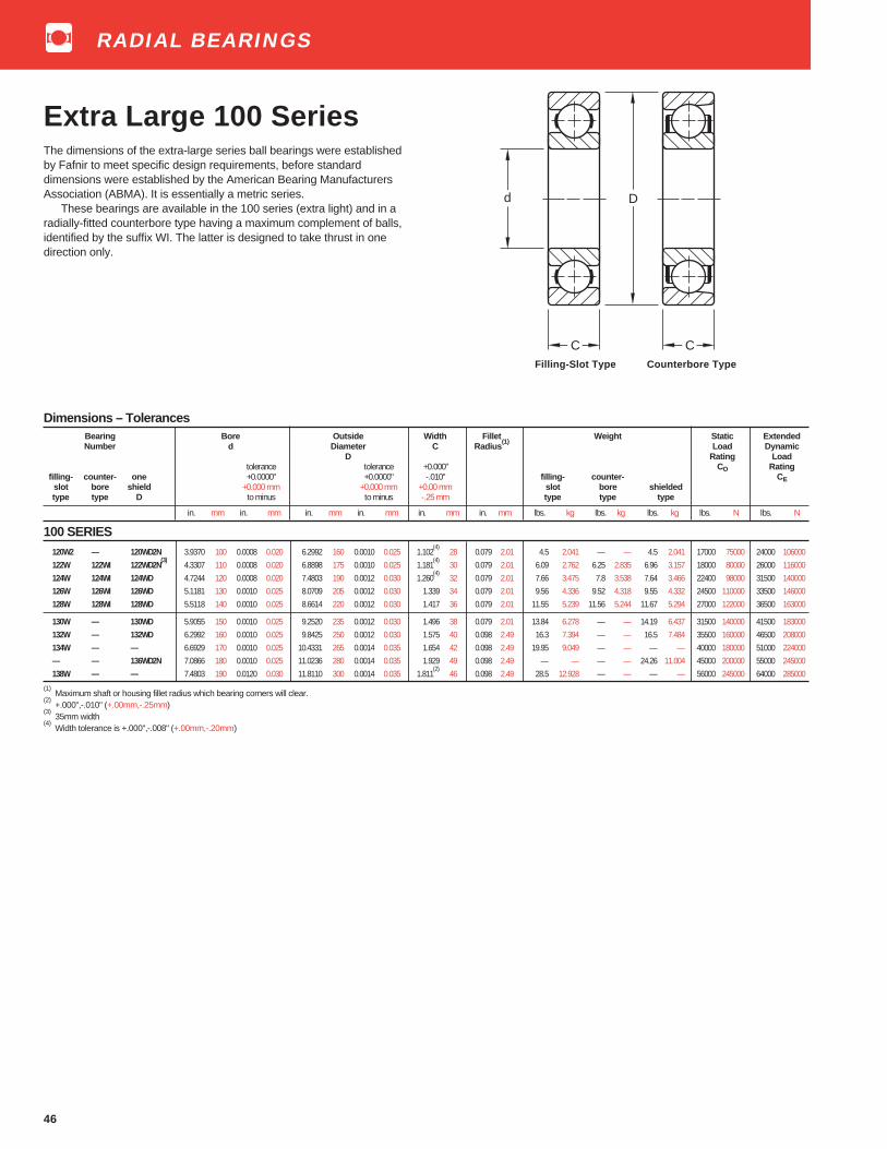
46
Extra Large 100 SeriesThe dimensions of the extra-large series ball bearings were establishedby Fafnir to meet specific design requirements, before standarddimensions were established by the American Bearing ManufacturersAssociation (ABMA). It is essentially a metric series.
These bearings are available in the 100 series (extra light) and in aradially-fitted counterbore type having a maximum complement of balls,identified by the suffix WI. The latter is designed to take thrust in onedirection only.
Dimensions – TolerancesBearing Bore Outside Width Fillet Weight Static ExtendedNumber d Diameter C Radius
(1)Load Dynamic
D Rating Loadtolerance tolerance +0.000" CO Rating
filling- counter- one +0.0000" +0.0000" -.010" filling- counter- C Eslot bore shield +0.000 mm +0.000 mm +0.00 mm slot bore shieldedtype type D to minus to minus -.25 mm type type type
in. mm in. mm in. mm in. mm in. mm in. mm lbs. kg lbs. kg lbs. kg lbs. N lbs. N
100 SERIES120W2 — 120WD2N 3.9370 100 0.0008 0.020 6.2992 160 0.0010 0.025 1.102
(4)28 0.079 2.01 4.5 2.041 — — 4.5 2.041 17000 75000 24000 106000
122W 122WI 122WD2N(3)
4.3307 110 0.0008 0.020 6.8898 175 0.0010 0.025 1.181(4)
30 0.079 2.01 6.09 2.762 6.25 2.835 6.96 3.157 18000 80000 26000 116000124W 124WI 124WD 4.7244 120 0.0008 0.020 7.4803 190 0.0012 0.030 1.260
(4)32 0.079 2.01 7.66 3.475 7.8 3.538 7.64 3.466 22400 98000 31500 140000
126W 126WI 126WD 5.1181 130 0.0010 0.025 8.0709 205 0.0012 0.030 1.339 34 0.079 2.01 9.56 4.336 9.52 4.318 9.55 4.332 24500 110000 33500 146000128W 128WI 128WD 5.5118 140 0.0010 0.025 8.6614 220 0.0012 0.030 1.417 36 0.079 2.01 11.55 5.239 11.56 5.244 11.67 5.294 27000 122000 36500 163000
130W — 130WD 5.9055 150 0.0010 0.025 9.2520 235 0.0012 0.030 1.496 38 0.079 2.01 13.84 6.278 — — 14.19 6.437 31500 140000 41500 183000132W — 132WD 6.2992 160 0.0010 0.025 9.8425 250 0.0012 0.030 1.575 40 0.098 2.49 16.3 7.394 — — 16.5 7.484 35500 160000 46500 208000134W — — 6.6929 170 0.0010 0.025 10.4331 265 0.0014 0.035 1.654 42 0.098 2.49 19.95 9.049 — — — — 40000 180000 51000 224000— — 136WD2N 7.0866 180 0.0010 0.025 11.0236 280 0.0014 0.035 1.929 49 0.098 2.49 — — — — 24.26 11.004 45000 200000 55000 245000138W — — 7.4803 190 0.0120 0.030 11.8110 300 0.0014 0.035 1.811
(2)46 0.098 2.49 28.5 12.928 — — — — 56000 245000 64000 285000
(1) Maximum shaft or housing fillet radius which bearing corners will clear.
(2) +.000",-.010" (+.00mm,-.25mm)
(3) 35mm width
(4) Width tolerance is +.000",-.008" (+.00mm,-.20mm)
C
D
C
d
Filling-Slot Type Counterbore Type
RADIAL BEARINGS

48
Light 7200WN SeriesThe angular contact light 7200WN series is dimensionally interchange-able with the radial 200 series. The features of the 7000WN seriesinclude a refined bore diameter.
A single bearing is recommended for applications in which the thrustload is in one direction or, in the case of combined loads, the thrust loadis high in relation to the radial load. A duplex pair is recommended forapplication where thrust is present in both directions or where axialdisplacement of the shaft must be restricted. For exceptionally highthrust loads in one direction, a tandem pair can be utilized opposed by athird bearing.
Sizes 7201K through 7203WN have a 20° contact angle and anylon cage. Sizes 7204WN through 7218WN have a 40° contact angleand a one-piece, ball piloted, pressed brass cage. Larger sizes 7219WNthrough 7230WN have a 40° contact angle and a one-piece, outer ringpiloted high-strength machined bronze cage.
DIMENSIONS – TOLERANCESBearing Bore Outside Diameter Width Fillet Wt. Static ExtendedNumber d D C Radius (1) Load Dynamic
tolerance tolerance tolerance Rating Load+0.0000" +0.0000" +0.0000" Co Rating
+0.000 mm +0.000 mm +0.000 mm CEto minus to minus to minus
in. mm in. mm in. mm in. mm in. mm in. mm in. mm lbs. kg lbs. N lbs. N
7201K 0.4724 12 0.0003 0.008 1.2598 32 0.00045 0.011 0.3937 10 0.005 0.12 0.024 0.6 0.08 0.036 630 2790 1600 71007202W 0.5906 15 0.0003 0.008 1.3780 35 0.00045 0.011 0.4331 11 0.005 0.12 0.024 0.6 0.1 0.045 1060 4700 2320 103007203W 0.6693 17 0.0003 0.008 1.5748 40 0.00045 0.011 0.4727 12 0.005 0.12 0.024 0.6 0.15 0.068 1560 6930 3200 142007204WN
(2) (3)0.7874 20 0.0004 0.010 1.8504 47 0.00045 0.011 0.5512 14 0.005 0.12 0.039 1.0 0.23 0.104 1830 8100 3800 16800
7205WN(3)
0.9843 25 0.0004 0.010 2.0472 52 0.0005 0.013 0.5906 15 0.005 0.12 0.039 1.0 0.29 0.132 2120 9400 3750 16600
7206WN 1.1811 30 0.0004 0.010 2.4409 62 0.0005 0.013 0.6299 16 0.005 0.12 0.039 1.0 0.46 0.209 3050 13500 5200 230007207WN 1.3780 35 0.0004 0.010 2.8346 72 0.0005 0.013 0.6693 17 0.005 0.12 0.039 1.0 0.63 0.286 4150 18000 6950 308007208WN 1.5748 40 0.0004 0.010 3.1496 80 0.0005 0.013 0.7087 18 0.005 0.12 0.039 1.0 0.73 0.331 5200 23000 8150 360007209WN 1.7717 45 0.0004 0.010 3.3465 85 0.0006 0.015 0.7480 19 0.005 0.12 0.039 1.0 0.96 0.435 5850 25900 9150 405007210WN 1.9685 50 0.0004 0.010 3.5433 90 0.0006 0.015 0.7874 20 0.005 0.12 0.039 1.0 1.12 0.508 6400 28400 9500 42500
7211WN 2.1654 55 0.0004 0.010 3.9370 100 0.0006 0.015 0.8268 21 0.006 0.15 0.059 1.5 1.4 0.635 8150 36200 11800 520007212WN 2.3622 60 0.0004 0.010 4.3307 110 0.0006 0.015 0.8661 22 0.006 0.15 0.059 1.5 1.84 0.835 10000 44000 14300 630007213WN 2.5591 65 0.0004 0.010 4.7244 120 0.0006 0.015 0.9055 23 0.006 0.15 0.059 1.5 2.34 1.061 11800 52400 16300 724007214WN 2.7559 70 0.0004 0.010 4.9213 125 0.0007 0.018 0.9449 24 0.006 0.15 0.059 1.5 2.58 1.17 12900 57300 17600 780007215WN 2.9528 75 0.0004 0.010 5.1181 130 0.0007 0.018 0.9843 25 0.006 0.15 0.059 1.5 2.8 1.27 13200 58000 17600 78000
7216WN 3.1496 80 0.0004 0.010 5.5118 140 0.0007 0.018 1.0236 26 0.006 0.15 0.079 2.0 3.27 1.483 15600 65500 20400 915007217WN 3.3465 85 0.0005 0.013 5.9055 150 0.0007 0.018 1.1024 28 0.008 0.20 0.079 2.0 4.62 2.096 18300 76500 23600 1060007218WN 3.5433 90 0.0005 0.013 6.2992 160 0.0010 0.025 1.1811 30 0.008 0.20 0.079 2.0 5.66 2.567 21200 88000 27000 119000
7219WN MBR 3.7402 95 0.0005 0.013 6.6929 170 0.0010 0.025 1.2600 32 0.008 0.20 0.079 2.0 6.67 3.025 22800 93000 30000 1330007220WN MBR 3.9370 100 0.0005 0.013 7.0866 180 0.0010 0.025 1.3390 34 0.008 0.20 0.079 2.0 7.62 3.46 25500 106000 33500 146000
7222WN MBR 4.3307 110 0.0005 0.013 7.8740 200 0.0012 0.030 1.4960 38 0.008 0.20 0.079 2.0 11.38 5.162 32500 134000 39000 1730007224WN MBR 4.7244 120 0.0005 0.013 8.4646 215 0.0012 0.030 1.5750 40 0.008 0.20 0.079 2.0 14.01 6.354 36500 160000 42500 1880007226WN MBR 5.1181 130 0.0007 0.018 9.0551 230 0.0012 0.030 1.5750 40 0.010 0.25 0.098 2.5 16.63 7.543 43000 176000 47500 211000
7228WN MBR 5.5118 140 0.0007 0.018 9.8425 250 0.0012 0.030 1.6540 42 0.010 0.25 0.098 2.5 21.24 9.634 47500 200000 50000 2240007230WN MBR 5.9055 150 0.0007 0.018 10.6299 270 0.0014 0.035 1.7720 45 0.010 0.25 0.098 2.5 25.84 11.72 56000 240000 56000 248000
(1) Maximum shaft or housing fillet radius which bearing corners will clear.
(2) Also available as W design.
(3) Also available with 20° contact angle and nylon cage.
Note: 7208WN-7212WN also available with a one piece, high strength machined bronze retainer (MBR).This cage can be quoted on the other sizes by request.
D
C
d D
C
d
7207-7218WN 7219-7230WN MBR40° Contact Angle 40 ° Contact Angle
SINGLE ROW ANGULAR CONTACT BEARINGS
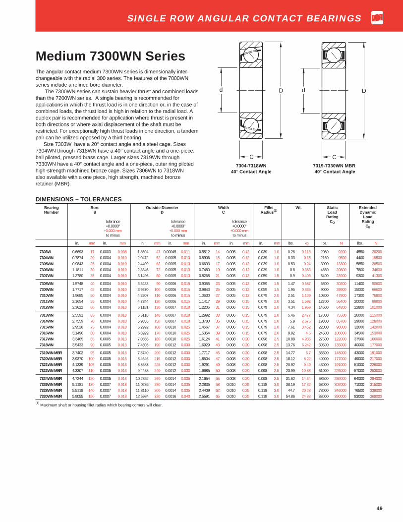
49
DIMENSIONS – TOLERANCESBearing Bore Outside Diameter Width Fillet Wt. Static ExtendedNumber d D C Radius (1) Load Dynamic
Rating Loadtolerance tolerance tolerance CO Rating+0.0000" +0.0000" +0.0000" CE
+0.000 mm +0.000 mm +0.000 mmto minus to minus to minus
in. mm in. mm in. mm in. mm in. mm in. mm in. mm lbs. kg lbs. N lbs. N
7303W 0.6693 17 0.0003 0.008 1.8504 47 0.00045 0.011 0.5512 14 0.005 0.12 0.039 1.0 0.26 0.118 2080 9200 4550 202007304WN 0.7874 20 0.0004 0.010 2.0472 52 0.0005 0.013 0.5906 15 0.005 0.12 0.039 1.0 0.33 0.15 2160 9590 4400 195007305WN 0.9843 25 0.0004 0.010 2.4409 62 0.0005 0.013 0.6693 17 0.005 0.12 0.039 1.0 0.53 0.24 3000 13300 5850 265007306WN 1.1811 30 0.0004 0.010 2.8346 72 0.0005 0.013 0.7480 19 0.005 0.12 0.039 1.0 0.8 0.363 4650 20800 7800 346007307WN 1.3780 35 0.0004 0.010 3.1496 80 0.0005 0.013 0.8268 21 0.005 0.12 0.059 1.5 0.9 0.408 5400 23900 9300 41300
7308WN 1.5748 40 0.0004 0.010 3.5433 90 0.0006 0.015 0.9055 23 0.005 0.12 0.059 1.5 1.47 0.667 6800 30200 11400 506007309WN 1.7717 45 0.0004 0.010 3.9370 100 0.0006 0.015 0.9843 25 0.005 0.12 0.059 1.5 1.95 0.885 9000 39900 15000 666007310WN 1.9685 50 0.0004 0.010 4.3307 110 0.0006 0.015 1.0630 27 0.005 0.12 0.079 2.0 2.51 1.139 10800 47900 17300 768007311WN 2.1654 55 0.0004 0.010 4.7244 120 0.0006 0.015 1.1417 29 0.006 0.15 0.079 2.0 3.51 1.592 12700 56400 20000 888007312WN 2.3622 60 0.0004 0.010 5.1181 130 0.0007 0.018 1.2205 31 0.006 0.15 0.079 2.0 4.34 1.969 14600 64800 22800 101000
7313WN 2.5591 65 0.0004 0.010 5.5118 140 0.0007 0.018 1.2992 33 0.006 0.15 0.079 2.0 5.46 2.477 17000 75500 26000 1150007314WN 2.7559 70 0.0004 0.010 5.9055 150 0.0007 0.018 1.3780 35 0.006 0.15 0.079 2.0 5.9 2.676 19300 85700 29000 1280007315WN 2.9528 75 0.0004 0.010 6.2992 160 0.0010 0.025 1.4567 37 0.006 0.15 0.079 2.0 7.61 3.452 22000 98000 32000 1420007316WN 3.1496 80 0.0004 0.010 6.6929 170 0.0010 0.025 1.5354 39 0.006 0.15 0.079 2.0 9.92 4.5 24500 108000 34500 1530007317WN 3.3465 85 0.0005 0.013 7.0866 180 0.0010 0.025 1.6124 41 0.008 0.20 0.098 2.5 10.88 4.936 27500 122000 37500 1660007318WN 3.5433 90 0.0005 0.013 7.4803 190 0.0012 0.030 1.6929 43 0.008 0.20 0.098 2.5 13.76 6.242 30500 135000 40000 177000
7319WN MBR 3.7402 95 0.0005 0.013 7.8740 200 0.0012 0.030 1.7717 45 0.008 0.20 0.098 2.5 14.77 6.7 33500 148000 43000 1910007320WN MBR 3.9370 100 0.0005 0.013 8.4646 215 0.0012 0.030 1.8504 47 0.008 0.20 0.098 2.5 18.12 8.22 40000 177000 49000 2170007321WN MBR 4.1339 105 0.0005 0.013 8.8583 225 0.0012 0.030 1.9291 49 0.008 0.20 0.098 2.5 20.92 9.49 43000 191000 51000 2260007322WN MBR 4.3307 110 0.0005 0.013 9.4488 240 0.0012 0.030 1.9685 50 0.008 0.20 0.098 2.5 23.99 10.88 51000 226000 57000 253000
7324WN MBR 4.7244 120 0.0005 0.013 10.2362 260 0.0014 0.035 2.1654 55 0.008 0.20 0.098 2.5 31.62 14.34 58500 259000 64000 2840007326WN MBR 5.1181 130 0.0007 0.018 11.0236 280 0.0014 0.035 2.2835 58 0.010 0.25 0.118 3.0 38.19 17.32 68000 302000 71000 3150007328WN MBR 5.5118 140 0.0007 0.018 11.8110 300 0.0014 0.035 2.4409 62 0.010 0.25 0.118 3.0 44.7 20.28 78000 346000 76500 3390007330WN MBR 5.9055 150 0.0007 0.018 12.5984 320 0.0016 0.040 2.5591 65 0.010 0.25 0.118 3.0 54.86 24.88 88000 390000 83000 368000
(1) Maximum shaft or housing fillet radius which bearing corners will clear.
Medium 7300WN SeriesThe angular contact medium 7300WN series is dimensionally inter-changeable with the radial 300 series. The features of the 7000WNseries include a refined bore diameter.
The 7300WN series can sustain heavier thrust and combined loadsthan the 7200WN series. A single bearing is recommended forapplications in which the thrust load is in one direction or, in the case ofcombined loads, the thrust load is high in relation to the radial load. Aduplex pair is recommended for application where thrust is present inboth directions or where axial displacement of the shaft must berestricted. For exceptionally high thrust loads in one direction, a tandempair can be utilized opposed by a third bearing.
Size 7303W have a 20° contact angle and a steel cage. Sizes7304WN through 7318WN have a 40° contact angle and a one-piece,ball piloted, pressed brass cage. Larger sizes 7319WN through7330WN have a 40° contact angle and a one-piece, outer ring pilotedhigh-strength machined bronze cage. Sizes 7306WN to 7318WNalso available with a one piece, high strength, machined bronzeretainer (MBR).
D
C
d D
C
d
7304-7318WN 7319-7330WN MBR40° Contact Angle 40 ° Contact Angle
SINGLE ROW ANGULAR CONTACT BEARINGS
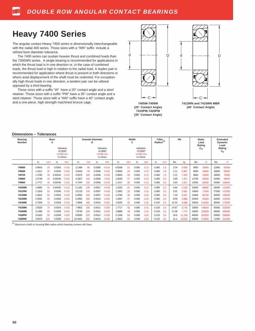
50
Heavy 7400 SeriesThe angular contact Heavy 7400 series is dimensionally interchangeablewith the radial 400 series. Those sizes with a “WN” suffix include arefined bore diameter tolerance.
The 7400 series can sustain heavier thrust and combined loads thanthe 7300WN series. A single bearing is recommended for applications inwhich the thrust load is in one direction or, in the case of combinedloads, the thrust load is high in relation to the radial load. A duplex pair isrecommended for application where thrust is present in both directions orwhere axial displacement of the shaft must be restricted. For exception-ally high thrust loads in one direction, a tandem pair can be utilizedopposed by a third bearing.
Those sizes with a suffix “W” have a 20° contact angle and a steelretainer. Those sizes with a suffix “PW” have a 35° contact angle and asteel retainer. Those sizes with a “WN” suffix have a 40° contact angleand a one-piece, high-strength machined bronze cage.
D
C
d D
C
d
Dimensions – TolerancesBearing Bore Outside Diameter Width Fillet Wt. Static ExtendedNumber d D C Radius
(1)Load Dynamic
Rating Loadtolerance tolerance tolerance CO Rating+0.0000" +0.0000" +0.0000" CE
+0.000 mm +0.000 mm +0.000 mmto minus to minus to minus
in. mm in. mm in. mm in. mm in. mm in. mm in. mm lbs. kg lbs. N lbs. N
7405W 0.9843 25 0.0004 0.010 3.1496 80 0.0005 0.013 0.8268 21 0.005 0.12 0.060 1.5 2.04 0.925 5850 25900 12000 533007406W 1.1811 30 0.0004 0.010 3.5433 90 0.0006 0.015 0.9055 23 0.005 0.12 0.060 1.5 2.11 0.957 8000 35500 15600 690007407W 1.3780 35 0.00045 0.012 3.9370 100 0.0006 0.015 0.9843 25 0.005 0.12 0.060 1.5 2.21 1.002 9650 42800 18000 799007408W 1.5748 40 0.00045 0.012 4.3307 110 0.0006 0.015 1.0630 27 0.005 0.12 0.080 2.0 2.89 1.311 12700 56400 22400 995007409W 1.7717 45 0.00045 0.012 4.7244 120 0.0006 0.015 1.1417 29 0.005 0.12 0.080 2.0 3.63 1.647 14000 62000 24000 106000
7410WN 1.9685 50 0.00045 0.012 5.1181 130 0.0007 0.018 1.2205 31 0.005 0.12 0.080 2.0 4.84 2.195 15000 66600 26000 1150007411PW 2.1654 55 0.0006 0.015 5.5118 140 0.0007 0.018 1.2992 33 0.006 0.15 0.080 2.0 5.91 2.681 16000 71000 27500 1220007412WN 2.3622 60 0.0004 0.010 5.9055 150 0.0007 0.018 1.3780 35 0.006 0.15 0.080 2.0 7.18 3.257 19300 85700 30500 1350007413WN 2.5591 65 0.0006 0.015 6.2992 160 0.0010 0.025 1.4567 37 0.006 0.15 0.080 2.0 8.59 3.896 20400 91500 32000 1420007414WN 2.7559 70 0.0006 0.015 7.0866 180 0.0010 0.025 1.6535 42 0.006 0.15 0.100 2.5 12.54 5.688 26000 115500 39000 173000
7415WN 2.9528 75 0.0004 0.010 7.4803 190 0.0012 0.030 1.7717 45 0.006 0.15 0.100 2.5 14.87 6.745 33500 148000 45500 2020007416WN 3.1496 80 0.0006 0.015 7.8740 200 0.0012 0.030 1.8898 48 0.006 0.15 0.100 2.5 17.08 7.747 34500 153000 46500 2060007418PW 3.5433 90 0.0008 0.020 8.8583 225 0.0012 0.030 2.1268 54 0.008 0.20 0.120 3.0 24.6 11.159 45000 200000 53000 2360007420PW 3.9370 100 0.0008 0.020 10.4331 265 0.0014 0.036 2.3622 60 0.008 0.20 0.120 3.0 41.1 18.643 63000 279000 71000 315000
(1) Maximum shaft or housing fillet radius which bearing corners will clear.
7405W-7409W 7412WN and 7415WN MBR(20° Contact Angle) (40 ° Contact Angle)
7410PW-7420PW(35° Contact Angle)
DOUBLE ROW ANGULAR CONTACT BEARINGS

51
Light 5200 SeriesLight 5200 series ball bearings have the same bores and outsidediameters as the corresponding bearings in the 200 series single rowradial type.
Double row angular contact ball bearings meet the demand forincreased axial and radial rigidity in applications where the design limitsspace.
These bearings are available in both conrad and maximum capacitytypes. Suffix K denotes conrad type i.e., 5203K. Suffix W or no suffixdenotes maximum capacity type i.e., 5212W, 5213.
DIMENSIONS – TOLERANCESBearing Bore Outside Diameter Width Fillet Contact Wt. Static ExtendedNumber d D C Radius
(1)Angle Load Dynamic
tolerance tolerance Rating Load+0.0000" +0.0000" +0.000",-0.005" Co Rating
+0.000 mm +0.000 mm +0.00 mm,-0.12 mm CEto minus to minus frac. decimal
in. mm in. mm in. mm in. mm in. in. mm in. mm lbs. kg lbs. N lbs. N
5200K(2)
0.3937 10 0.0003 0.008 1.1811 30 0.00035 0.009 9⁄16 0.562 14.27 0.024 0.6 20° 0.12 0.054 1140 5060 2400 106005201K
(2)0.4724 12 0.0003 0.008 1.2598 32 0.00045 0.012 5⁄8 0.625 15.88 0.024 0.6 20° 0.15 0.068 1060 4700 2040 9060
5202K(2)
0.5906 15 0.0003 0.008 1.3780 35 0.00045 0.012 5⁄8 0.625 15.88 0.024 0.6 20° 0.16 0.073 1600 7100 3050 135005203K
(2)0.6693 17 0.0003 0.008 1.5748 40 0.00045 0.012 11⁄16 0.688 17.48 0.024 0.6 20° 0.23 0.104 2080 9200 3800 16800
5204K(2)
0.7874 20 0.0004 0.010 1.8504 47 0.00045 0.012 13⁄16 0.812 20.62 0.039 1.0 20° 0.36 0.163 2850 12600 5100 22600
5205K(2)
0.9843 25 0.0004 0.010 2.0472 52 0.0005 0.013 13⁄16 0.812 20.62 0.039 1.0 20° 0.41 0.186 3400 15100 5600 248005206K 1.1811 30 0.0004 0.010 2.4409 62 0.0005 0.013 15⁄16 0.938 23.83 0.039 1.0 20° 0.65 0.295 4900 21700 7800 346005206W 1.1811 30 0.0004 0.010 2.4409 62 0.0005 0.013 15⁄16 0.938 23.83 0.039 1.0 30° 0.65 0.295 6100 27000 8800 390005207K 1.3780 35 0.00045 0.012 2.8346 72 0.0005 0.013 1 1⁄16 1.062 26.97 0.039 1.0 20° 1.06 0.481 6550 29000 10200 450005207W 1.3780 35 0.00045 0.012 2.8346 72 0.0005 0.013 1 1⁄16 1.062 26.97 0.039 1.0 30° 1.06 0.481 8300 36800 11600 515005208K 1.5748 40 0.00045 0.012 3.1496 80 0.0005 0.013 1 3⁄16 1.188 30.17 0.039 1.0 20° 1.32 0.566 7650 33900 11600 515005208W 1.5748 40 0.00045 0.012 3.1496 80 0.0005 0.013 1 3⁄16 1.188 30.17 0.039 1.0 30° 1.32 0.599 10600 47000 14000 620005209K 1.7717 45 0.00045 0.012 3.3456 85 0.0006 0.015 1 3⁄16 1.188 30.17 0.039 1.0 20° 1.54 0.699 8800 39000 12900 570005209W 1.7717 45 0.00045 0.012 3.3456 85 0.0006 0.015 1 3⁄16 1.188 30.17 0.039 1.0 30° 1.54 0.699 11600 51500 14600 64800
5210K 1.9685 50 0.00045 0.012 3.5433 90 0.0006 0.015 1 3⁄16 1.188 30.17 0.039 1.0 20° 1.66 0.753 10000 44400 14000 620005210W 1.9685 50 0.00045 0.012 3.5433 90 0.0006 0.015 1 3⁄16 1.188 30.17 0.039 1.0 30° 1.66 0.753 12700 56000 15000 666005211K 2.1654 55 0.0006 0.015 3.9370 100 0.0006 0.015 1 5⁄16 1.312
(4)33.32 0.059 1.5 20° 2.29 1.039 12700 71000 17300 76000
5211W 2.1654 55 0.0006 0.015 3.9370 100 0.0006 0.015 1 5⁄16 1.312(4)
33.32 0.059 1.5 30° 2.29 1.039 16000 62000 19000 840005212K 2.3622 60 0.0006 0.015 4.3307 110 0.0006 0.015 1 7⁄16 1.438
(4)36.53 0.059 1.5 20° 3.06 1.388 14000 88800 19300 85000
5212W 2.3622 60 0.0006 0.015 4.3307 110 0.0006 0.015 1 7⁄16 1.438(4)
36.53 0.059 1.5 30° 3.06 1.388 20000 72000 23800 1030005213K 2.5591 65 0.0006 0.015 4.7244 120 0.0006 0.015 1 1⁄2 1.500
(4)38.10 0.059 1.5 20° 4.24 1.923 17300 76800 22800 101000
5213(3)
2.5591 65 0.0006 0.015 4.7244 120 0.0006 0.015 1 1⁄2 1.500(4)
38.10 0.059 1.5 30° 4.24 1.923 20800 92000 22400 995005214K 2.7559 70 0.0006 0.015 4.9213 125 0.0007 0.018 1 9⁄16 1.562
(4)39.67 0.059 1.5 20° 4.62 2.096 19000 84000 24500 108000
5214(3)
2.7559 70 0.0006 0.015 4.9213 125 0.0007 0.018 1 9⁄16 1.562(4)
39.67 0.059 1.5 30° 4.62 2.096 28500 126000 31500 139000
5215K 2.9528 75 0.0006 0.015 5.1181 130 0.0007 0.018 1 5⁄8 1.625(4)
41.28 0.059 1.5 20° 5.15 2.336 19300 85700 24500 1080005215
(3)2.9528 75 0.0006 0.015 5.1181 130 0.0007 0.018 1 5⁄8 1.625
(4)41.28 0.059 1.5 30° 5.15 2.336 31000 137000 32500 144000
5216(3)
3.1496 80 0.0006 0.015 5.5118 140 0.0007 0.018 1 3⁄4 1.750(4)
44.45 0.079 2.0 30° 6.32 2.867 36500 162000 38000 1680005217
(3)3.3456 85 0.0008 0.020 5.9055 150 0.0007 0.018 1 15⁄16 1.938
(5)49.23 0.079 2.0 30° 8 3.629 40000 177000 42500 188000
5218W 3.5433 90 0.0008 0.020 6.2992 160 0.0010 0.025 2 1⁄16 2.062(5)
52.37 0.079 2.0 20° 9.96 4.518 43000 191000 45500 2020005219
(3)3.7402 95 0.0008 0.020 6.6929 170 0.0010 0.025 2 3⁄16 2.188
(5)55.58 0.079 2.0 30° 11.93 5.411 53000 235000 55000 244000
5220W 3.9370 100 0.0008 0.020 7.0866 180 0.0010 0.025 2 3⁄8 2.375(5)
60.32 0.079 2.0 20° 14.42 6.541 57000 253000 58500 2590005222 4.3307 110 0.0008 0.020 7.8740 200 0.0012 0.030 2 3⁄4 2.750
(5)69.85 0.079 2.0 30° 20.95 9.503 76500 339000 73500 326000
(1) Maximum shaft or housing fillet radius which bearing corners will clear.
(2) Sizes have PRB molded nylon retainers.
(3) These sizes have contact angle converging inside the bearing.
(4) Width tolerance is +.000 to -.006" (+.00mm to -.15mm).
(5) Width tolerance is +.000 to -.008" (+.00mm to -.20mm).
Note: See page 53 for Shield and Snap Ring Combinations.
Dd
C
DOUBLE ROW ANGULAR CONTACT BEARINGS

52
Medium 5300 SeriesMedium 5300 series ball bearings have the same bores and outsidediameters as the corresponding bearings in the 300 series single rowradial type.
Double row angular contact ball bearings meet the demand forincreased axial and radial rigidity in applications where the design limitsspace.
These bearings are available in both conrad and maximum capacitytypes. Suffix K denotes conrad type i.e., 5303K. Suffix W or no suffixdenotes maximum capacity type i.e., 5312W, 5319.
Dimensions – TolerancesBearing Bore Outside Diameter Width Fillet Contact Wt. Static ExtendedNumber d D C Radius (1) Angle Load Dynamic
tolerance tolerance Rating Load+0.0000" +0.0000" +0.000",-0.005" CO Rating
+0.000 mm +0.000 mm +0.00 mm,-0.12 mm CEto minus to minus frac. decimal
in. mm in. mm in. mm in. mm in. in. mm in. mm lbs. kg lbs. N lbs. N
5302 0.5906 15 0.0003 0.008 1.6535 42 0.00045 0.012 3⁄4 0.750 19.05 0.039 1.0 20° 0.31 0.141 2080 9200 3800 168005303K 0.6693 17 0.0003 0.008 1.8504 47 0.00045 0.012 7⁄8 0.875 22.22 0.039 1.0 20° 0.42 0.191 2850 12600 5100 226005304K
(2)0.7874 20 0.0004 0.010 2.0472 52 0.0005 0.013 7⁄8 0.875 22.22 0.039 1.0 20° 0.49 0.222 3450 15300 6400 28400
5305K(2)
0.9843 25 0.0004 0.010 2.4409 62 0.0005 0.013 1 1.000 25.40 0.039 1.0 20° 0.81 0.367 4750 21100 8500 377005306K 1.1811 30 0.0004 0.010 2.8346 72 0.0005 0.013 1 3⁄16 1.188 30.17 0.039 1.0 20° 1.35 0.612 6550 29000 10600 470005306W 1.1811 30 0.0004 0.010 2.8346 72 0.0005 0.013 1 3⁄16 1.188 30.17 0.039 1.0 30° 1.35 0.612 9300 41000 14000 62000
5307K 1.3780 35 0.00045 0.012 3.1496 80 0.0005 0.013 1 3⁄8 1.375 34.93 0.059 1.5 20° 1.92 0.871 8300 36000 13400 595005307W 1.3780 35 0.00045 0.012 3.1496 80 0.0005 0.013 1 3⁄8 1.375 34.93 0.059 1.5 30° 1.92 0.871 10800 47900 15600 692005308K 1.5748 40 0.00045 0.012 3.5433 90 0.0006 0.015 1 7⁄16 1.438 36.53 0.059 1.5 20° 2.51 1.139 10400 46000 16300 724005308W 1.5748 40 0.00045 0.012 3.5433 90 0.0006 0.015 1 7⁄16 1.438 36.53 0.059 1.5 30° 2.51 1.139 15000 66600 20400 906005309K 1.7717 45 0.00045 0.012 3.9370 100 0.0006 0.015 1 9⁄16 1.562 39.67 0.059 1.5 20° 3.16 1.433 12700 56400 19600 870005309W 1.7717 45 0.00045 0.012 3.9370 100 0.0006 0.015 1 9⁄16 1.562 39.67 0.059 1.5 30° 3.16 1.433 18300 81000 24000 1060005310K 1.9685 50 0.00045 0.012 4.3307 110 0.0006 0.015 1 3⁄4 1.750 44.45 0.079 2.0 20° 4.61 2.091 16600 73000 25000 1110005310W 1.9685 50 0.00045 0.012 4.3307 110 0.0006 0.015 1 3⁄4 1.750 44.45 0.079 2.0 30° 4.61 2.091 22000 97000 28500 1260005311W 2.1654 55 0.0006 0.015 4.7244 120 0.0006 0.015 1 15⁄16 1.938
(3)49.22 0.079 2.0 20° 6 2.722 25500 113000 32500 144000
5312W 2.3622 60 0.0006 0.015 5.1181 130 0.0007 0.018 2 1⁄8 2.125(3)
53.98 0.079 2.0 20° 7.54 3.420 34000 151000 43000 1910005313W 2.5591 65 0.0006 0.015 5.5118 140 0.0007 0.018 2 5⁄16 2.312
(3)58.72 0.079 2.0 20° 9.17 4.160 39000 173000 48000 213000
5314W 2.7559 70 0.0006 0.015 5.9055 150 0.0007 0.018 2 1⁄2 2.500(3)
63.50 0.079 2.0 20° 11.82 5.362 44000 195000 54000 2390005315W 2.9528 75 0.0006 0.015 6.2992 160 0.0010 0.025 2 11⁄16 2.689
(3)68.30 0.079 2.0 20° 14.17 6.428 50000 222000 60000 266000
5316W 3.1496 80 0.0006 0.015 6.6929 170 0.0010 0.025 2 11⁄16 2.688(3)
68.28 0.079 2.0 20° 16.24 7.366 56000 248000 64000 284000
5317W 3.3465 85 0.0008 0.020 7.0866 180 0.0010 0.025 2 7⁄8 2.875(4)
73.02 0.098 2.5 20° 19.46 8.827 63000 279000 69500 3080005318W 3.5433 90 0.0008 0.020 7.4803 190 0.0012 0.030 2 7⁄8 2.875
(4)73.02 0.098 2.5 20° 21.2 9.616 69500 308000 75000 333000
5319 3.7402 95 0.0008 0.020 7.8740 200 0.0012 0.030 3 1⁄16 3.062(4)
77.77 0.098 2.5 30° 25.49 11.562 72000 319000 75000 3330005320W 3.9370 100 0.0008 0.020 8.4646 215 0.0012 0.030 3 1⁄4 3.250
(4)82.55 0.098 2.5 20° 31.57 14.320 85000 377000 85000 377000
5322W 4.3307 110 0.0008 0.020 9.4488 240 0.0012 0.030 3 5⁄8 3.625(4)
92.08 0.098 2.5 20° 44.43 20.153 108000 479000 102000 453000
5324W 4.7244 120 0.0008 0.020 10.2362 260 0.0014 0.035 4 1⁄8 4.125(4)
104.78 0.098 2.5 20° 62.37 28.291 125000 555000 112000 4970005328W 5.5118 140 0.0010 0.025 11.8110 300 0.0014 0.035 4 1⁄2 4.500
(5)114.30 0.118 3.0 20° 84 38.102 140000 630000 129000 570000
(1) Maximum shaft or housing fillet radius which bearing corners will clear.
(2) Sizes have PRB molded nylon retainers.
(3) Width tolerance is +.000 to -.006" (+.00mm to -.15mm).
(4) Width tolerance is +.000 to 0-.008" (+.00mm to -.20mm).
(5) Width tolerance is +.000 to -.010" (+.00mm to -.25 mm)
Note: See opposite page for Shield and Snap Ring Combinations.
Dd
C
DOUBLE ROW ANGULAR CONTACT BEARINGS

53
Shield and Snap Ring Combinations
5200 SERIES
Bearing Width Wt. Bearing Snap Ring(1)
Wt.Number +0.000",-.005" Number
+0.00 mm,-.12mmfraction decimal O.D. Thickness Offset
in. in mm lbs. kg in. mm in. mm in. mm lbs kg
5200KDD2 5⁄8 0.625(3)
15.88 0.12 0.054 — 1 23⁄64 34.5 0.042 1.07 0.120 3.05 — —5201KD(DD) 5⁄8 0.625 15.88 0.14 0.064 — 1 7⁄16 36.5 0.042 1.07 0.120 3.05 — —— — — — — — — 1 35⁄64 39.3 0.042 1.07 0.120 3.05 — —5203KD(KDD3) 11⁄16 0.688 17.48 0.35 0.159 5203KDG 1 3⁄4 44.4 0.042 1.07 0.120 3.05 0.28 0.1275204KD 13⁄16 0.812 20.62 0.26 0.118 5204KG 2 1⁄16 52.4 0.042 1.07 0.136 3.45 0.33 0.15
5205KD 7⁄8 0.875 22.22 0.45 0.204 5205KG 2 17⁄64 57.5 0.042 1.07 0.136 3.45 0.44 0.25206WD 1 1⁄16 1.062 26.97 0.74 0.336 5206WG 2 21⁄32 67.5 0.065 1.65 0.190 4.83 0.73 0.3315207WD 1 3⁄16 1.188 30.17 1.21 0.546 — 3 5⁄64 78.2 0.065 1.65 0.190 4.83 — —5208WD 1 3⁄16 1.188 30.17 1.46 0.662 — 3 13⁄32 86.5 0.065 1.65 0.190 4.83 — —5209WD 1 3⁄16 1.188 30.17 1.57 0.712 5209WG 3 19⁄32 91.3 0.065 1.65 0.190 4.83 1.59 0.721
5210WD 1 5⁄16 1.312 33.32 1.8 0.816 5210WG 3 51⁄64 96.4 0.095 2.41 0.220 5.59 1.7 0.7715211WD 1 5⁄16 1.312 33.32 2.3 1.043 5211WG 4 3⁄16 106.4 0.095 2.41 0.220 5.59 2.35 1.0665212WD 1 9⁄16 1.562 39.67 3.3 1.497 5212WG 4 37⁄64 116.3 0.095 2.41 0.220 5.59 3.14 1.4245213WD — — — — — — 5 3⁄32 129.4 0.109 2.77 0.265 6.73 — —5214D
(2)1 9⁄16 1.562 39.67 4.71 2.137 — 5 19⁄64 134.5 0.109 2.77 0.265 6.73 — —
— — — — — — 5215G(2)
5 1⁄2 139.7 0.109 2.77 0.265 6.73 5.13 2.3275216DD
(2)1 7⁄8 1.875 47.62 6.75 3.062 5216G
(2)5 57⁄64 149.6 0.109 2.77 0.297 7.54 6.53 2.962
— — — — — — 5217G(2)
6 9⁄32 159.5 0.109 2.77 0.297 7.54 8.21 3.7245218WD 2 1⁄16 2.062 52.37 9.93 4.504 — 6 43⁄64 169.5 0.109 2.77 0.297 7.54 — —— — — — — — 5219G
(2)7 3⁄16 182.6 0.12 3.05 0.339 8.61 12.12 5.498
5300 SERIESBearing Width Wt. Bearing Snap Ring (1) Wt.Number +0.000",-.005" Number
(4)
+0.00 mm,-.12mmfraction decimal O.D. Thickness Offset
in. in mm lbs. kg in. mm in. mm in. mm lbs kg
— — — — — — 5303KG 2 1⁄16 52.4 0.042 1.07 0.136 3.45 0.5 0.227— — — — — — 5304KG 2 17⁄64 57.6 0.042 1.07 0.136 3.45 0.51 0.231— — — — — — 5305KG 2 21⁄32 67.5 0.065 1.65 0.190 4.83 0.83 0.3765306WD 1 5⁄16 1.312 33.32 1.41 0.64 5306WG 3 5⁄64 78.2 0.065 1.65 0.190 4.83 1.34 0.608
5307WD 1 1⁄2 1.500 38.10 1.89 0.857 5307WG 3 13⁄32 86.5 0.065 1.65 0.190 4.83 1.78 0.8075308WD 1 9⁄16 1.562 39.67 2.52 1.143 5308WG 3 51⁄64 96.4 0.095 2.41 0.220 5.59 2.43 1.1025309WD 1 11⁄16 1.688 42.88 3.67 1.665 5309WG 4 3⁄16 106.4 0.095 2.41 0.220 5.59 3.22 1.4615310WD 1 7⁄8 1.875 47.62 4.45 2.019 5310WG 4 37⁄64 116.3 0.095 2.41 0.220 5.59 4.26 1.9325311D
(4)2 1⁄16 2.062 52.37 6.23 2.826 5311WG 5 3⁄32 129.4 0.109 2.77 0.265 6.73 6.15 2.789
5312D(4)
2 1⁄4 2.250 57.15 7.54 3.42 5312WG 5 1⁄2 139.7 0.109 2.77 0.265 6.73 7.7 3.4935313D
(4)2 7⁄16 2.438 61.72 10.28 4.663 5313WG 5 57⁄64 149.6 0.109 2.77 0.297 7.54 9.46 4.291
— — — — — — 5314WG 6 9⁄32 159.5 0.109 2.77 0.297 7.54 12.05 5.466
(1) The snap ring is normally packaged separately in the box with the bearing.
(4) Ring widths are different for these parts. Contact Torrington Sales Engineer to validate size.
(2) These sizes have contact angle converging inside bearing.
(3) Inner ring width is .7500" (19.05mm).
OFFSET
THICKNESS
O.D.
One Shield D Open Type G One Shield DG
Snap Ring (Wireloc) (1)
DOUBLE ROW ANGULAR CONTACT BEARINGS

Radial and Angular Contact BearingsSpecial Duty Bearings
Page
Nomenclature
Tri-Ply Seal Series,
Non-Relubricatable Type Cylindrical O.D.. . . . . . . 35
Tri-Ply Seal Series,
Non-Relubricatable Type Spherical O.D. . . . . . . . . 36
Tri-Ply Seal Series, Relubricatable Type . . . . . . . . . . . 37
Tri-Ply Seal Series, Disk Harrow Units . . . . . . . . . . . . 38
Hex Bore Series . . . . . . . . . . . . . . . . . . . . . . . . . . . . . . 39
Light 200 Series, R-Seal Type . . . . . . . . . . . . . . . . . . . 40
Farm Radial Specials. . . . . . . . . . . . . . . . . . . . . . 40-43
XLS Series, Conrad and
Maximum Capacity Types . . . . . . . . . . . . . . . 44-45
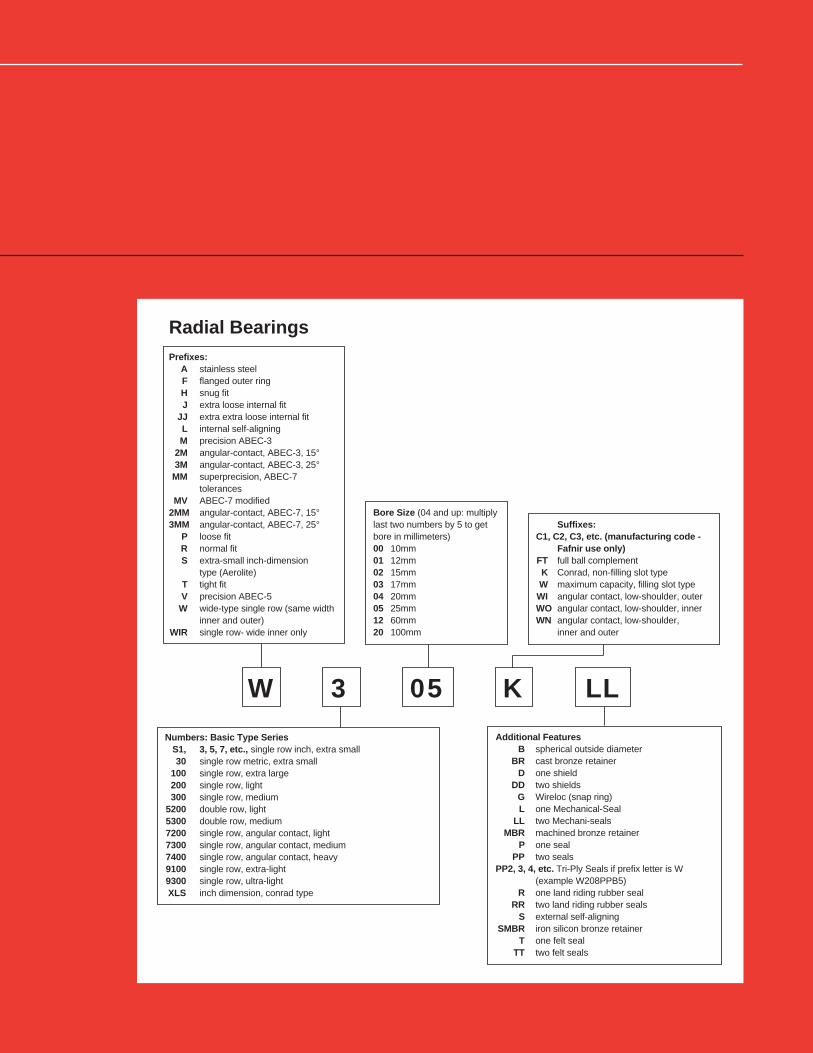
Radial BearingsPrefixes:
A stainless steelF flanged outer ringH snug fitJ extra loose internal fit
JJ extra extra loose internal fitL internal self-aligningM precision ABEC-3
2M angular-contact, ABEC-3, 15°3M angular-contact, ABEC-3, 25°
MM superprecision, ABEC-7tolerances
MV ABEC-7 modified2MM angular-contact, ABEC-7, 15°3MM angular-contact, ABEC-7, 25°
P loose fitR normal fitS extra-small inch-dimension
type (Aerolite)T tight fitV precision ABEC-5
W wide-type single row (same widthinner and outer)
WIR single row- wide inner only
Suffixes:C1, C2, C3, etc. (manufacturing code -
Fafnir use only)FT full ball complementK Conrad, non-filling slot typeW maximum capacity, filling slot type
WI angular contact, low-shoulder, outerWO angular contact, low-shoulder, innerWN angular contact, low-shoulder,
inner and outer
Bore Size (04 and up: multiplylast two numbers by 5 to getbore in millimeters)00 10mm01 12mm02 15mm03 17mm04 20mm05 25mm12 60mm20 100mm
Numbers: Basic Type SeriesS1, 3, 5, 7, etc., single row inch, extra small30 single row metric, extra small
100 single row, extra large200 single row, light300 single row, medium
5200 double row, light5300 double row, medium7200 single row, angular contact, light7300 single row, angular contact, medium7400 single row, angular contact, heavy9100 single row, extra-light9300 single row, ultra-lightXLS inch dimension, conrad type
Additional FeaturesB spherical outside diameter
BR cast bronze retainerD one shield
DD two shieldsG Wireloc (snap ring)L one Mechanical-Seal
LL two Mechani-sealsMBR machined bronze retainer
P one sealPP two seals
PP2, 3, 4, etc. Tri-Ply Seals if prefix letter is W(example W208PPB5)
R one land riding rubber sealRR two land riding rubber seals
S external self-aligningSMBR iron silicon bronze retainer
T one felt sealTT two felt seals
W 3 05 K LL

35
Tri-Ply Seal SeriesNon-Relubricatable TypeCylindrical O.D.Tri-Ply Seal ball bearings are designed for environments where severecontamination is present such as agricultural tillage equipment. The one-piece Tri-Ply Seals incorporate a highly effective seal design molded toan exterior shroud cap to provide exceptionally effective protectionagainst the loss of lubricant and the entrance of wet or abrasivecontaminants. A seven piece Tri-Ply construction is standard on certainsizes. The shroud cap nests closely with the outside seal and helpsprotect the rubber seal members from wrappage and abrasion.
A feature of these bearings is their balanced design identified bydeep races, large balls and extra wide or heavy, shock-resistant innerand outer rings. The use of Tri-Ply Seal bearings simplifies housingdesigns, and their extra inner ring width provides greater support on theshaft. For speeds in excess of 500 RPM, consult the EngineeringDepartment.
ROUND BOREBearing Type-Fig. Bore Outside Diameter Ring Width Balls Wt. Static ExtendedNumber d D +0.000",-0.005" Load Dynamic
+0.00,-.12 mm Rating Loadtolerance tolerance CO Rating+0.0000" +0.0000" CE
+0.000 mm +0.000 mm B Cto minus tonomnus Inner Outer No. Size
in. mm in. mm in. mm in. mm in. mm in. mm No. size lbs. kg lbs. N lbs. N
W208PP10 1-1 1.5005 38.113 0.0005 0.013 3.1496 80 0.0005 0.013 1.688 42.96 0.827 21.00 9 1⁄2 1.5 0.680 4500 19900 8300 36800
W210PP8 2- 1.5300 38.860 0.0100 0.250 3.5433 90 0.0006 0.015 1.188 30.18 1.188 30.18 10 1⁄2 1.97 0.894 5200 23000 9000 39900
W210PP2 2- 1.9380 49.230 0.0005 0.013 3.5433 90 0.0006 0.015 1.188 30.18 1.188 30.18 10 1⁄2 1.69 0.767 5200 23000 9000 39900
W211PP2 2-2 2.1880 55.580 0.0006 0.015 3.9370 100 0.0006 0.015 1.312 33.34(1)
1.312 33.34 10 9⁄16 2.33 1.056 6550 29000 11000 48800
W214PP2 2- 2.7559 70.000 0.0006 0.015 4.9213 125 0.0008 0.020 1.562 39.69(1)
1.562 39.69 10 11⁄16 4.19 1.901 9800 43500 16000 71000
W315PP2 2- 3.0056 76.342 0.0006 0.015 6.2992 160 0.0010 0.025 2.688 68.26(1)
2.688 68.26 8 1 1⁄16 13.13 5.956 17300 76800 29000 128000
(1)Inner and outer width tolerance is .000" to .006" (.00mm to -.15mm)
SQUARE BOREBearing Type-Fig. Shaft Size Outside Diameter Ring Width Balls Wt. Static ExtendedNumber D +0.000",-0.005" Load Dynamic
+0.00,-.12 mm Rating Loadtolerance CO Rating+0.0000" CE
+0.000 mm B Cto minus Inner Outer No. Size
in. mm in. mm in. mm in. mm in. mm in lbs. kg lbs. N lbs. N
W208PP6 1–1 1 25.4 3.1496 80 0.0005 0.013 1.438 36.51 0.709 18 9 1⁄2 1.62 0.73 4500 19900 8300 36800
W208PP5 1–1 1 1⁄8 28.6 3.1496 80 0.0005 0.013 1.438 36.51 0.709 18 9 1⁄2 1.5 0.68 4500 19900 8300 36800
W208PP20 1–1 1 1⁄8 28.6 3.1496 80 0.0005 0.013 1.438 36.51 0.709 18 9 1⁄2 1.5 0.68 4500 19900 8300 36800
W208PP8 1–1 1 1⁄8 28.6 3.1496 80 0.0005 0.013 1.438 36.51 1.188 30.18 9 1⁄2 1.66 0.75 4500 19900 8300 36800
W211PP3 2–2 1 1⁄2 38.1 3.9370 100 0.0006 0.015 1.312 33.34(1)
1.312 33.34 10 9⁄16 2.79 1.27 6550 29000 11000 48800
W211PP5 1–2 1 1⁄2 38.1 4.0000 101.6 0.0006 0.015 1.75 44.45(1)
1.438 36.52 10 7⁄16 3.48 1.58 6550 29000 11000 48800
(1)Inner and outer width tolerance is .000" to .006" (.00mm to -.15mm)
Type 1 Type 2
Figure 1 Figure 2 Figure 3
D
B
dD
B
d
C
RADIAL BEARINGS

36
Tri-Ply Seal SeriesNon-Relubricatable TypeSpherical O.D.These Tri-Ply Seal bearings are similar in design and features tothose shown on page 35 except for a spherical O.D.
ROUND BOREBearing Type-Fig. Bore Outside Diameter Ring Width Balls Stamping Wt. Static ExtendedNumber d D +0.000",-0.005" Size Load Dynamic
+0.00,-.12 mm Rating Loadtolerance tolerance CO Rating+0.0000" +0.0000" CE
+0.000 mm +0.000 mm B Cto minus to minus Inner Outer No. Size
in. mm in. mm in. mm in. mm in. mm in. mm in. lbs. kg lbs. N lbs. N
W208PPB7 1–1 1.1880 3.170 0.0005 0.013 3.150 80 0.0005 0.013 1.188 30.18 0.709 18.00 9 1⁄2 80MS 1.41 0.64 4500 19900 8300 36800
W208PPB2 1– 1.5005 38.113 0.0005 0.013 3.150 80 0.0005 0.013 1.688 42.96 0.709 18.00 9 1⁄2 80MS 1.59 0.721 4500 19900 8300 36800
W208PPB23 1–1 1.5005 38.113 0.0005 0.013 3.150 80 0.0005 0.013 1.688 42.96 1.188 30.18 9 15⁄32 80MS 1.5 0.68 3550 15600 7200 32000
W209PPB2 2–2 1.7717 45.000 0.0005 0.013 3.346 85 0.0006 0.015 1.188 30.18 1.188 30.18 9 1⁄2 85MS 1.44 0.653 4550 20200 8300 36800
W209PPB4 2–2 1.5350 39.000 0.0100 0.250 3.346 85 0.0006 0.015 1.188 30.18 1.188 30.18 9 1⁄2 85MS 1.65 0.748 4550 20200 8300 36800
W210PPB2 2– 1.9380 49.230 0.0005 0.013 3.543 90 0.0006 0.015 1.188 30.18 1.188 30.18 10 1⁄2 90MS 1.56 0.708 5200 23000 9000 39900
W210PPB5 2– 1.7850 45.340 0.0100 0.250 3.543 90 0.0006 0.015 1.188 30.18 1.188 30.18 10 1⁄2 90MS 1.75 0.794 5200 23000 9000 39900
W211PPB2 2–2 2.1880 55.580 0.0006 0.015 3.937 100 0.0006 0.015 1.312 33.34(1)
1.312 33.34 10 9⁄16 100MS 3.63 0.966 6550 29000 11000 48800
W214PPB2 2– 2.7559 70.000 0.0006 0.015 4.921 125 0.0008 0.020 1.562 39.69(1)
1.562 39.69 10 11⁄16 — 3.96 1.796 9800 43500 16000 71000
W214PPB9 1– 2.7660 70.260 0.0010 0.025 4.921 125 0.0008 0.020 1.750 44.45(1)
1.102 28.00 10 11⁄16 — 3.96 1.796 9800 43500 16000 71000
(1)Inner and outer width tolerance is .000" to -.006" (.00mm to -.15mm)
SQUARE BORE
Bearing Type-Fig. Shaft Size Outside Diameter Ring Width Balls Stamping Wt. Static ExtendedNumber D +0.000",-0.005" Size Load Dynamic
+0.00,-.12 mm Rating Loadtolerance CO Rating+0.0000" CE
+0.000 mm B Cto minus Inner Outer No. Size
in. mm in. mm in. mm in. mm in. mm in. lbs. kg lbs. N lbs. N
W208PPB13 1–1 7⁄8 22.2 3.1496 80 0.0005 0.013 1.438 36.53 0.709 18.00 9 1⁄2 80MS 1.62 0.735 4500 19900 8300 36800
W208PPB6 1–1 1 25.4 3.1496 80 0.0005 0.013 1.438 36.53 0.709 18.00 9 1⁄2 80MS 1.59 0.721 4500 19900 8300 36800
W208PPB5 1–1 1 1⁄8 28.6 3.1496 80 0.0005 0.013 1.438 36.53 0.709 18.00 9 1⁄2 80MS 1.47 0.667 4500 19900 8300 36800
W209PPB5 1–2 1 1⁄4 31.8 3.3465 85 0.0006 0.015 1.438 36.53 1.188 30.18 9 1⁄2 85MS 1.75 0.794 4550 20200 8300 36800
W210PPB4 2– 1 1⁄8 28.6 3.5433 90 0.0006 0.015 1.188 30.18 1.188 30.18 10 1⁄2 90MS 2.11 0.957 5200 23000 9000 39900
W210PPB6 1– 1 1⁄8 28.6 3.5433 90 0.0006 0.015 1.438 36.53 1.188 30.18 10 1⁄2 90MS 2.25 1.021 5200 23000 9000 39900
W211PPB3 2–2 1 1⁄2 38.1 3.9370 100 0.0006 0.015 1.312 33.34(1)
1.312 33.34 10 9⁄16 100MS 2.66 1.207 6550 29000 11000 48800
(1) Inner and outer width tolerance is .000" to -.006" (.00mm to -.15mm)
Figure 1 Figure 2 Figure 3 Type 1 Type 2
D
B
dD
B
d
C
RADIAL BEARINGS

37
Bearing Type- Bore Outside Diameter Ring Width Balls L Wt. Static ExtendedNumber Fig. d D +0.000,-.005" Load Dynamic
tolerance tolerance +0.00,-0.12 mm Rating Load+0.0000" +0.0000" CO Rating
+0.000 mm +0.000 mm B C CEto minus to minus Inner Outer No. size
in. mm in. mm in. mm in. mm in. mm in. mm in. in. mm lbs. kg lbs. N lbs. N
GW209PPB4 4–2 1.5350 39.00 0.0100 0.250 3.3465 85 0.0006 0.015 1.188 30.18 1.188 30.18 9 1⁄2 0.346 8.79 1.65 0.748 4550 20200 8300 36800
GW209PPB2 4–2 1.7717 45.00 0.0005 0.013 3.3465 85 0.0006 0.015 1.188 30.18 1.188 30.18 9 1⁄2 0.346 8.79 1.44 0.653 4550 20200 8300 36800
GW209PPB11 2–2 1.7810 45.24 0.0100 0.250 3.3465 85 0.0006 0.015 1.438 36.53 0.866 22.00 9 1⁄2 0.179 4.55 1.37 0.621 4550 20200 8300 36800
GW210PP3 3– 1.4065 37.53 0.0005 0.013 3.5433 90 0.0006 0.015 1.188 30.18 1.188 30.18 10 1⁄2 0.355 9.02 2.25 1.021 5200 23000 9000 39900
GW210PPB5 4– 1.7850 45.34 0.0100 0.250 3.5433 90 0.0006 0.015 1.188 30.18 1.188 30.18 10 1⁄2 0.355 9.02 1.75 0.794 5200 23000 9000 39900
GW210PPB2 4– 1.9380 49.23 0.0005 0.013 3.5433 90 0.0006 0.015 1.188 30.18 1.188 30.18 10 1⁄2 0.355 9.02 1.5 0.68 5200 23000 9000 39900
GW210PP9(1)
2– 1.9450 49.40 0.0070 0.180 3.5433 90 0.0006 0.015 1.438 36.53 0.906 23.00 10 1⁄2 0.185 4.70 1.75 0.794 5200 23000 9000 39900
GW211PPB13 2–2 1.7850 45.34 0.0100 0.250 3.9370 100 0.0006 0.015 1.312 33.34 0.984 25.00 10 9⁄16 0.299 5.82 2.02 0.916 6550 29000 11000 48800
GW211PPB10 4–2 1.9380 49.23 0.0006 0.015 3.9370 100 0.0006 0.015 1.312 33.34(2)
0.312 33.34 10 9⁄16 0.392 9.96 2.26 1.025 6550 29000 11000 48800
GW211PPB14 2–2 2.0150 51.18 0.0100 0.250 3.9370 100 0.0006 0.015 1.312 33.34(2)
0.984 25.00 10 9⁄16 0.229 5.82 2 0.907 6550 29000 11000 48800
GW211PP2 3–2 2.1880 55.58 0.0006 0.015 3.9370 100 0.0006 0.015 1.312 33.34(2)
1.312 33.34 10 9⁄16 0.392 9.96 3 1.361 6550 29000 11000 48800
GW211PPB2 4–2 2.1880 55.58 0.0006 0.015 3.9370 100 0.0006 0.015 1.312 33.34(2)
1.312 33.34 10 9⁄16 0.392 9.96 2.62 1.188 6550 29000 11000 48800
GW211PPB8 2–2 2.1880 55.58 0.0006 0.015 3.9370 100 0.0006 0.015 1.312 33.34(2)
0.984 25.00 10 9⁄16 0.229 5.82 1.85 0.839 6550 29000 11000 48800
GW211PPB9 2–2 2.1950 55.75 0.0070 0.180 3.9370 100 0.0006 0.015 1.562 39.69(2)
0.984 25.00 10 9⁄16 0.213 5.41 2.02 0.916 6550 29000 11000 48800
GW214PPB6 2– 2.6881 68.28 0.0006 0.015 4.9213 125 0.0008 0.020 2.688 68.26(2)
1.102 28.00 10 11⁄16 0.218 5.54 4.75 2.155 9800 43500 16000 71000
GW214PP2 3– 2.7559 70.00 0.0006 0.015 4.9213 125 0.0008 0.020 1.562 39.69(2)
1.562 39.69 10 11⁄16 0.414 10.52 4.19 1.901 9800 43500 16000 71000
GW214PPB2 4– 2.7559 70.00 0.0006 0.015 4.9213 125 0.0008 0.020 1.562 39.69(2)
1.562 39.69 10 11⁄16 0.414 10.52 3.96 1.796 9800 43500 16000 71000
GW214PPB5 1– 2.7559 70.00 0.0006 0.015 4.9213 125 0.0008 0.020 2.438 61.90(2)
1.562 39.69 10 11⁄16 0.414 10.52 4.75 2.155 9800 43500 16000 71000
GW216PPB3 2–3 3.0100 76.45 0.0100 0.250 5.5118 140 0.0008 0.020 2.500 63.50(2)
1.181 30.00 11 23⁄32 0.240 6.10 — — 12200 54000 18300 81000
GW216PP5 3–3 2.5150 63.88 0.0100 0.250 5.5118 140 0.0008 0.020 2.500 63.50(2)
1.181 30.00 11 23⁄32 0.240 6.10 — — 12200 54000 18300 81000
Type 1 Type 2 Type 3 Type 4
Shaft SizeSQUARE BORE in. mm
GW208PPB6 2–1 1 25.4 3.1496 80 0.0005 0.013 1.438 36.53 0.827 21.00 9 1⁄2 0.223 5.66 1.75 0.794 4500 19900 8300 36800
GW208PPB5 2–1 11⁄8 28.6 3.1496 80 0.0005 0.013 1.438 36.53 0.827 21.00 9 1⁄2 0.223 5.66 1.47 0.667 4500 19900 8300 36800
GW208PPB8 1–1 11⁄8 28.6 3.1496 80 0.0005 0.013 1.438 36.53 1.188 30.18 9 1⁄2 0.329 8.36 1.75 0.794 4500 19900 8300 36800
GW208PPB17 3–1 11⁄8 28.6 3.3755 85.738 0.0005 0.013 1.438 36.53 1.188 30.18 9 1⁄2 0.326 8.28 20.4 0.925 4500 19900 8300 36800
GW209PPB5 1–2 11⁄4 31.8 3.3456 85 0.0006 0.015 1.438 36.53 1.188 30.18 9 1⁄2 0.346 8.79 1.75 0.794 4550 20200 8300 36800
GW209PPB8 2–2 11⁄4 31.8 3.3456 85 0.0006 0.015 1.438 36.53 0.866 22.00 9 1⁄2 0.179 4.55 1.65 0.748 4550 20200 8300 36800
GW210PP4 3– 11⁄8 28.6 3.5433 90 0.0006 0.015 1.188 30.18 1.188 30.18 10 1⁄2 0.355 9.02 2.31 1.048 5200 23000 9000 39900
GW210PPB4 4– 11⁄8 28.6 3.5433 90 0.0006 0.015 1.188 30.18 1.188 30.18 10 1⁄2 0.355 9.02 1.75 0.794 5200 23000 9000 39900
GW211PP3 3–2 11⁄2 38.1 3.9370 100 0.0006 0.015 1.312 33.34(2)
1.312 33.34 10 9⁄16 0.392 9.96 2.79 1.266 6550 29000 11000 48800
GW211PPB3 4–2 11⁄2 38.1 3.9370 100 0.0006 0.015 1.312 33.34(2)
1.312 33.34 10 9⁄16 0.392 9.96 2.66 1.207 6550 29000 11000 48800
GW211PP17 3–2 11⁄2 38.1 3.9370 100 0.0006 0.015 1.75 44.45(2)
1.312 33.34 10 9⁄16 0.392 9.96 2.62 1.188 6550 29000 11000 48800
GW214PPB4 4– 2 50.8 4.9213 125 0.0008 0.020 1.562 39.69(2)
1.562 39.69 10 11⁄16 0.414 10.52 4.75 2.155 9800 43500 16000 71000
GW216PPB4 2–3 13⁄4 44.4 5.5118 140 0.0008 0.020 2.5 63.50(2)
1.181 30.00 11 23⁄32 0.240 6.1 — — 12200 54000 18300 81000
GW216PP2(1)
2–3 21⁄4 57.2 5.5118 140 0.0008 0.020 2.5 63.50(2)
1.181 30.00 11 23⁄32 0.240 6.1 — — 12200 54000 18300 81000
GW216PPB2 2–3 21⁄4 57.2 5.5118 140 0.0008 0.020 2.5 63.50(2)
1.181 30.00 11 23⁄32 0.240 6.1 — — 12200 54000 18300 81000
(1) Cylindrical O.D.
(2) Inner and outer width tolerance is .000" to –.006" (.00mm to-.15mm).
B
CL
D
B
d
LC
B
L
B
L
Figure 1 Figure 2 Figure 3
Tri-Ply Seal SeriesRelubricatable TypeThese Tri-Ply Seal bearings are similar in design and features to thoseshown on the preceding two pages and have a provision for relubrication.
ROUND BORE
RADIAL BEARINGS

38
Tri-Ply SeriesDisk Harrow UnitsThe disk harrow unit is the answer to versitility in design. For extraspecial design needs this unit incorporates a Tri-Ply bearing mounted intwo stampings, riveted together with two “O” rings.
The disk harrow unit is available in two basic size groups, oneincorporating a 209 and one a 211 bearing. Both size groups offer theseoutstanding features.• Dynamic alignment capability (±3°).• Shroud effect from close clearance of stamping to inner ring.• Relubrication.• One unit piece for ease of handling and assembly.• Fitting flange mates with outer ring milled recess, preventing possibility
of outer ring circumferential movement.• Stampings are case hardened to minimize wear.• Units are equipped with nylon retainer, molded one-piece seals and
patented notched outer ring seal grooves.
209 SERIESUnit Shaft B H 2 J N1 N L G H A A 1 Static Extended
Number Diam. Ref. Load DynamicRating Load
Co RatingCE
in. in. in. in. in. in. in. in. in. in. in. lbs lbs
DHU 11⁄2 R–209 1 1⁄2 RD. 1 11⁄16 4 5 21⁄32 17⁄32 5 2.279 2 23⁄64 1 43⁄64 17⁄64 4000 8150
DHU 11⁄8 S–209 1 1⁄8 SQ. 1 11⁄16 4 5 21⁄32 17⁄32 5 2.279 2 23⁄64 1 43⁄64 17⁄64 4000 8150
DHU 13⁄4 R–209 1 3⁄4 RD. 1 11⁄16 4 5 21⁄3217⁄32 5 2.279 2 23⁄64 1 43⁄64
17⁄64 4000 8150
DHU 11⁄4S–209 1 1⁄4 SQ. 1 3⁄4 4 5 21⁄3217⁄32 5 2.279 2 23⁄64 1 43⁄64
17⁄64 4000 8150
DHU 491 A 1 3⁄4 RD. 1 3⁄4 4 5 21⁄3217⁄32 5 2.279 2 23⁄64 1 43⁄64
17⁄64 4000 8150
211 SERIESDHU 11⁄2 S–211 1 1⁄2 SQ. 2 4 5 1⁄2 19⁄32
17⁄32 5 1⁄2 2.746 2 7⁄8 1 15⁄1619⁄64 5600 10800
DHU 13⁄4 R–211 1 3⁄4 RD. 2 1⁄8 4 5 1⁄2 19⁄3217⁄32 5 1⁄2 2.746 2 7⁄8 1 15⁄16
19⁄64 5600 10800
DHU 23⁄16 R–211 2 3⁄16 RD. 2 3⁄16 4 5 1⁄2 19⁄3217⁄32 5 1⁄2 2.746 2 7⁄8 1 15⁄16
19⁄64 5600 10800
209 METRIC SERIESUnit Shaft B H 2 J N1 N L G H A A 1 Static Extended
Number Diam. Ref. Load DynamicRating Load
Co RatingCE
mm mm mm mm mm mm mm mm mm mm mm N N
DHU 30S–209 30 SQ. 43 101.6 127 16.7 13.5 127 57.9 59.9 42.5 6.7 18000 36500
DHU 40R–209 40 SQ. 43 101.6 127 16.7 13.5 127 57.9 59.9 42.5 6.7 18000 36500
DHU 45R–209 45 RD. 43 101.6 127 16.7 13.5 127 57.9 59.9 42.5 6.7 18000 36500
211 METRIC SERIESDHU 40S–211 40 SQ. 51 113.5 139.7 15.1 13.5 139.7 69.7 73 49.2 7.5 25000 48000
DHU 50R–211 50 RD. 51 113.5 139.7 15.1 13.5 139.7 69.7 73 49.2 7.5 25000 48000
DHU 55R–211 55 RD. 51 113.5 139.7 15.1 13.5 139.7 69.7 73 49.2 7.5 25000 48000
L SQUARE
N
N
45°
JBOLT CIRCLE
4 - HOLES
1 G
A
H
B
A
H
MINIMUMFRAME
OPENING
2
1
RADIAL BEARINGS

39
Bearing Type Hex Hex Bore Outside Diameter Width F G Balls Wt Static ExtendedNumber Shaft A d D Load Dynamic
Size tolerance tolerance +0.0000 -0.005" Rating Load+0.000" Across +0.0000" +0.000 mm -0.12 mm CO Rating
Across -0.00 mm corners +0.000 mm C B CEFlats to plus min. to minus Outer Inner No. size
in. mm in. mm in. mm in. mm in. mm in. mm in. mm in. mm in. mm in. lbs. kg lbs. N lbs. N
NON-RELUBRICATABLE TYPE202KRR3 1 9⁄16 0.563 14.30 0.005 0.13 0.648 16.46 1.3780 35 0.0005 .013 0.433 11 0.512 13 — — — — 8 7⁄32 0.12 0.054 1000 4400 2360 10600
204KRR2 1 11⁄16 0.695 17.65 0.005 0.13 0.796 20.22 1.8504 47 0.0005 .013 0.551 14 0.825 20.96 — — — — 8 5⁄16 0.32 0.145 1400 6200 3200 14300
205KRR2 1 7⁄8 0.876 22.25 0.005 0.13 1.010 25.65 2.0472 52 0.0005 .013 0.591 15 1.000 25.4 — — — — 9 5⁄16 0.44 0.2 1560 6950 3450 15600
205KRRB2 2 7⁄8 0.876 22.25 0.005 0.13 1.010 25.65 2.0472 52 0.0005 .013 0.591 15 1.000 25.4 — — — — 9 5⁄16 0.44 0.2 1560 6950 3450 15600
205PPB13(1)
2 7⁄8 0.876 22.25 0.005 0.13 1.010 25.65 2.0472 52 0.0005 .013 0.591 15 1.000 25.4 1.680 42.67 0.795 20.19 9 5⁄16 0.44 0.2 1560 6950 3450 15600
206KPP3(1)
1 1 1.001 25.43 0.005 0.13 1.154 29.31 2.4409 62 0.0005 .013 0.630 16 0.945 24 2.050 52.07 0.770 19.56 9 3⁄8 0.76 0.345 2280 10000 4800 21600
206KPPB3(1)
2 1 1.001 25.43 0.005 0.13 1.154 29.31 2.4409 62 0.0005 .013 0.630 16 0.945 24 2.050 52.07 0.770 19.56 9 3⁄8 0.76 0.345 2280 10000 4800 21600
206KRR6 1 1 1.001 25.43 0.005 0.13 1.154 29.31 2.4409 62 0.0005 .013 0.630 16 0.945 24 2.050 52.07 0.770 19.56 9 3⁄8 0.75 0.34 2280 10000 4800 21600
206KRRB6 2 1 1.001 25.43 0.005 0.13 1.154 29.31 2.4409 62 0.0005 .013 0.630 16 0.945 24 2.050 52.07 0.770 19.56 9 3⁄8 0.75 0.34 2280 10000 4800 21600
207KPP3 1 1 1⁄4 1.251 31.77 0.005 0.13 1.433 36.40 2.8346 72 0.0005 .013 0.669 17 1.484 37.7 2.376 60.35 0.775 19.68 9 7⁄16 1 0.454 3050 13700 6400 28500
207KPPB3 2 1 1⁄4 1.251 31.77 0.005 0.13 1.433 36.40 2.8346 72 0.0005 .013 0.669 17 0.984 25 2.376 60.35 0.775 19.68 9 7⁄16 0.87 0.395 3050 13700 6400 28500
207KRRB9 2 1 1⁄8 1.126 28.60 0.005 0.13 1.298 32.97 2.8346 72 0.0005 .013 0.669 17 1.484 37.7 2.376 60.35 0.775 19.68 9 7⁄16 1 0.454 3050 13700 6400 28500
207KRRB12 2 1 1⁄8 1.126 28.60 0.005 0.13 1.298 32.97 2.8346 72 0.0005 .013 0.669 17 0.984 25 2.376 60.35 0.775 19.68 9 7⁄16 0.87 0.395 3050 13700 6400 28500
207KRR17 1 1 1⁄4 1.251 31.77 0.005 0.13 1.443 36.65 2.8346 72 0.0005 .013 0.669 17 0.984 25 2.376 60.35 0.775 19.68 9 7⁄16 0.87 0.395 3050 13700 6400 28500
207KRRB17 2 1 1⁄4 1.251 31.77 0.005 0.13 1.443 36.65 2.8346 72 0.0005 .013 0.669 17 0.984 25 2.376 60.35 0.775 19.68 9 7⁄16 0.87 0.395 3050 13700 6400 28500
W208PPB16(1)
2 1 1⁄4 1.251 31.77 0.005 0.13 1.443 36.65 3.1496 80 0.0005 .013 0.709 18 1.438 36.53 2.694 68.43 0.995 25.27 9 1⁄2 1.45 0.658 4000 17600 8150 36000
W208KRRB6 2 1 3⁄8 1.376 34.95 0.005 0.13 1.587 40.30 3.1496 80 0.0005 .013 0.827 21 1.438 36.53 2.694 68.43 0.927 23.54 9 1⁄2 — — 4000 17600 8150 36000
W208KRR8 1 1 1⁄4 1.251 31.77 0.005 0.13 1.443 36.65 3.1496 80 0.0005 .013 0.709 18 1.438 36.53 2.694 68.43 0.805 20.45 9 1⁄2 1.45 0.658 4000 17600 8150 36000
209KRRB2 2 1 1⁄2 1.501 38.12 0.005 0.13 1.732 43.99 3.3456 85 0.0006 0.015 0.748 19 1.181 30 2.908 73.86 0.916 23.27 9 1⁄2 1.27 0.576 4000 17600 8150 36000
W210PPB7(1)
2 1 5⁄8 1.626 41.30 0.005 0.13 1.876 47.65 3.5433 90 0.0006 0.015 1.188 30.18 1.188 30.18 — — — — 10 1⁄2 1.75 0.794 4500 19600 8800 39000
RELUBRICATAB LE TYPEG206KPP4
(1)3 1 1.001 25.43 0.005 0.13 1.152 29.26 2.4409 62 0.005 0.13 0.709 18 0.945 24 — — — — 9 3⁄8 0.62 0.281 2280 10000 4800 21600
G206KPPB4(1)
4 1 1.001 25.43 0.005 0.13 1.152 29.26 2.4409 62 0.005 0.13 0.709 18 0.945 24 2.050 52.07 0.770 19.56 9 3⁄8 0.61 0.277 2280 10000 4800 21600
G206KRRB6 4 1 1.001 25.43 0.005 0.13 1.152 29.26 2.4409 62 0.005 0.13 0.709 18 0.945 24 2.050 52.07 0.770 19.56 9 3⁄8 0.59 0.268 2280 10000 4800 21600
G207KPPB2(1)
4 1 1⁄8 1.126 28.60 0.005 0.13 1.298 32.97 2.8346 72 0.005 0.13 0.748 19 1.484 37.7 2.375 60.32 1.000 25.40 9 7⁄16 1 0.454 3050 13700 6400 28500
GW208KRRB5 4 1 1⁄4 1.251 31.77 0.005 0.13 1.443 36.65 3.1496 80 0.005 0.13 0.827 21 1.438 36.51 2.694 60.35 0.883 22.43 9 1⁄2 1.4 0.635 4000 17600 8150 36000
GW208PPB22(1)
2 1 1⁄4 1.255 31.88 0.005 0.13 1.447 36.75 3.1496 80 0.005 0.13 0.827 21 1.438 36.51 2.050 52.07 1.115 28.32 9 1⁄2 1.5 0.68 4000 17600 8150 36000
GC1200KPPB2(1)
1 3⁄4 1.751 44.48 0.005 0.13 2.020 51.31 3.9370 100 0.0006 0.015 0.984 25(2)
2.250 57.15 3.390 86.11 1.142 29.01 10 9⁄16 3.35 1.52 4500 19600 8800 39000
(1) Tri-Ply Seal bearing.
(2) Inner and outer ring tolerance is .000" to -.006" (.00mm to -15mm).
Hex Bore SeriesThis series is designed to be used either for outer or inner ring rotationin low speed, moderately loaded applications, primarily in agriculturalimplements and conveyors. The main advantage of these bearings isease of mounting; except for end-wise positioning by adjacent parts,
D
B
d
C
G
D
B
C
G
F
B
C
G
B
C
G
BB
C
G
B
C
G
B
G
d
A
Type 1 Type 2 Type 3 Type 4
no collars, setscrews or other locking devises are required to lockthe inner ring to the hex shaft. The tolerances of the hex bore inthis series are suitable for mounting on cold rolled hex shafting.
These bearings utilize the R type shroud seal.
RADIAL BEARINGS

40
Bearing Number 202NPP9Special Features■ 1⁄2 in. Bore
■ O.D. corner turned to a 3⁄4 in. radius
■ Special heavy stiff seals of Buna-N rubber
■ Crimped-in seal
Typical Applications
Cam Follower
Bearing Number 202KRR7
Special Features
■ 1⁄2 in. Bore
■ 11⁄2 in. O.D.
■ Thick outer ring
Typical Applications
Cam Follower
Light 200 Series R-Seal TypeThe 200 series R-Seal type consists of deep groove, Conrad-typebearings which incorporate a flare-out, contact R Seal. In this design asynthetic rubber impregnated washer is enclosed between two metalshields to give unsurpassed protection against contaminants.Because of the heavy contact seal, this series is normally employed inmoderate speed service.
Farm Radial Specials
Bearing Type Bore Outside Width E P K Fillet F Static ExtendedNumber d Diameter +0.000–.005" Radius
(1)Load Dynamic
D +0.00–.12 mm Rating Loadtolerance tolerance Co Rating+0.0000" +0.0000" CE
+0.000 mm +0.000 mm B Cto minus to minus Inner Outer Max. Max. Max.
in. mm in. mm in. mm in. mm in. mm in. mm in. mm in. mm in. mm in. mm in. mm lbs. N lbs. N
203KR2 3 0.6253 15.883 0.0003 0.008 1.5748 40 0.0005 0.013 0.551 14.00 0.472 12 — — — — — — 0.024 0.6 0.962 24.44 1060 4700 2450 10900203KRR2 1 0.6400 16.256 0.0050 0.130 1.5748 40 0.0005 0.013 0.720 18.29 0.472 12 — — — — — — 0.024 0.6 0.962 24.44 1060 4700 2450 10900203KRR5 1 0.5150 13.081 0.0050 0.130 1.5748 40 0.0005 0.013 0.720 18.29 0.472 12 — — — — — — 0.024 0.6 0.962 24.44 1060 4700 2450 10900203KRR7 1 0.6693 17 0.0003 0.008 1.5748 40 0.0005 0.013 0.654 16.61 0.472 12 — — — — — — 0.024 0.6 0.962 24.44 1060 4700 2450 10900204KR2 3 0.7505 19.063 0.0005 0.013 1.7805 45.225 0.0005 0.013 0.610 15.49 0.61 15.49 — — — — — — 0.039 1 1.131 28.73 1460 6500 3250 14400
204KRR3 1 0.7874 20 0.0004 0.010 1.8504 47 0.0005 0.013 0.699 17.75 0.551 14 — — — — — — 0.039 1 1.131 28.73 1460 6500 3250 14400205KR4 2 1.0005 25.413 0.0005 0.013 2.0472 52 0.0005 0.013 1.000 25.40 0.591 15 0.625 15.875 — — 1.68 42.67 0.039 1 1.331 33.81 1760 7800 3600 16000206KR7 2 1.1811 30 0.0004 0.010 2.4409 62 0.0005 0.013 0.945 24.00 0.63 16 0.700 17.78 — — 2.05 52.07 0.039 1 1.586 40.28 2550 11300 4900 21800206KRR8 1 1.1811 30 0.0004 0.010 2.4409 62 0.0005 0.013 0.945 24.00 0.63 16 — — 0.77 19.56 2.05 52.07 0.039 1 1.539 39.09 2250 11300 4900 21800207KRR 1 1.3780 35 0.0005 0.013 2.8346 72 0.0005 0.013 0.984 25.00 0.669 17 — — 0.775 19.68 2.376 60.35 0.039 1 1.848 46.94 3450 15000 6550 29000
208KRR2 1 1.5748 40 0.0005 0.013 3.1496 80 0.0005 0.013 1.063 27.00 0.827 21 — — 0.839 21.31 2.695 68.45 0.039 1 2.057 52.25 4500 20000 8300 36900209KRR3 1 1.7717 45 0.0005 0.013 3.3465 85 0.0005 0.013 1.063 27.00 0.827 21 — — 0.952 24.18 2.851 72.42 0.039 1 2.279 57.89 4550 20000 8300 36900210KRR 1 1.9685 50 0.0005 0.013 3.5433 90 0.0006 0.015 1.181 30.00 0.787 20 — — 0.946 24.03 3.055 77.6 0.039 1 2.473 62.81 5200 32100 9000 40000212KRR 1 2.3622 60 0.0006 0.015 4.3307 110 0.0006 0.015 1.417 36.00(2) 0.886 22 — — 1.182 30.02 3.932 99.87 0.039 1 3.01 76.45 8000 35500 13200 58600
(1) Maximum shaft or housing fillet radius which bearing corners will clear.
(2) Inner and outer width tolerance is .000" to .0006" (.00mm to -.15mm).
D
B
FdK
C
P
B
F K
C
E
B
F K
C
E
Type 1 Type 2 Type 3
Continued on the next page.
.015"
.005".4.1
3 /4 R19
.5669"
.5619"14.39914.272
1.5000"1.4995"38.10038.087
.505"
.500"12.812.7
.4331"
.4281"11.00010.874
38.10038.087
.505"
.500"12.812.7
.015"
.005".4.1
3 /4 R19
1.5000"1.4995"
RADIAL BEARINGS

41
Farm Radial Specials (continued)
Bearing Number203KRR3
Special Features■ 5⁄8 in. Bore■ 2 in. O.D.■ Thick outer ring
Typical ApplicationsCam FollowerGuide Rolls for Baler Plunger
Bearing Number203KRR6
Special Features■ 5⁄8 in. Bore■ 47 mm O.D.■ Thick outer ring
Typical ApplicationsIdler PulleyIdler Sprocket
Bearing Number203NPP9
Special Features■ 5⁄8 in. Bore■ Width .500"
Typical ApplicationsDisk Grain Drill
Bearing Number204RY2
Special Features■ 5⁄8 in. Bore■ Gothic Arch Race
Typical ApplicationsPlanterDouble Disk Opener
Bearing NumberP204RR6
Special Features■ 3⁄4 in. Bore■ 1.7805 in. O.D.■ Replaces 204KRNP2
Typical ApplicationsMower Spindle
Bearing Number204RR7
Special Features■ 3⁄4 in. Bore■ 1.7805 in. O.D.■ Replaces 204KRNP3
Typical ApplicationsRolling CultivatorDisk
Bearing Number205KR3
Special Features■ 3⁄4 in. Bore■ Excellent moment load capacity
available from special internalgeometry of races
■ Heavy contact flare-out typeR-Sealwith shroud cap
Typical ApplicationsDisk HillerPlanter
Bearing Number205KP6
Special Features■ 3⁄4 in. Bore■ Tri-Ply Seal on one side
with shroud cap
Typical ApplicationsRolling Cultivator
Continued on the next page.
.015"
.005".4.1
1"R25.4
.5906"
.5856"15.00014.874
2.0000"1.9995"50.80050.787
.6280"
.6277" 15.95115.944
.4724"
.4674"12.00011.872
1.8504"1.8499"47.00046.987
.640"
.635"16.2616.13
.720"
.715"18.28818.161
.510"
.500"12.95412.700
1.5748"1.5743"40.00039.987
.6260"
.6255"15.90015.888
1.7805"1.7800"45.22045.210
.631"
.626"16.03015.900
.610"
.605"15.49 15.37
.735"
.730"18.67 18.54
.610"
.605"15.49015.370
1.7805"1.7800"45.22545.212
.7505"
.7500"19.06319.050
.610"
.605"15.49015.370
1.7805"1.7800"45.22545.212
.755"
.750" 19.18 19.05
2.0472"2.0467"52.00051.986
.751"
.750"19.08 19.05
.700"
.695"17.78 17.65
.640"
.635"16.26 16.13
.281"7.14REF.
.700"
.695"17.78 17.65
2.0472"2.0467"52.00051.986
.756"
.751"19.20019.080
.921"
.916"23.39023.270
RADIAL BEARINGS

42
Farm Radial Specials (continued)Bearing Number205KRR6
Special Features■ 1⁄2 in. Bore■ Extended inner ring
Typical ApplicationsPotato Harvester
Bearing Number206KP2
Special Features■ Tri-Ply Seal on one side
with shroud cap
Typical ApplicationsCombine
Bearing Number207KRR14
Special Features■ 11⁄4 in. Bore
Typical ApplicationsDisk HarrowTransport Wheel
Bearing Number207KYY
Special Features■ Molded double lip seal
Typical ApplicationsDisk HarrowTransport Wheel
Bearing Number208NPPB5
Special Features■ 1 7⁄16 in. Bore■ PP Seals with shroud cap
Typical ApplicationsBaler Crank Pin
Bearing Number208PPB12
Special Features■ 11⁄8 in. Square Bore■ Molded Tri-Ply seal■ Heavy outer ring
Typical ApplicationsDisk Harrow
Bearing NumberW211PPB6
Special Features■ 11⁄2 in. Square Bore■ Tri-Ply seal with shroud cap■ Heavy outer ring
Typical ApplicationsDisk Harrow
Bearing NumberG1104KRXB2
Special Features■ Oil Seal on one side
Typical ApplicationsChain Case
2.0472"2.0467"52.00051.986
.515"
.510"13.08012.950
.5906"
.5856"15.00014.874
1.375"1.370"
34.92034.800
2.4409"2.4404"62.00061.986
1.1811"1.1807"30.00029.990
.6299"
.6249"16.00015.872
.9449"
.9399"24.00023.873
2.8346"2.8341"72.00071.986
1.2530"1.2525"31.82631.814
.6693"
.6643"17.00016.873
.9843"
.9793"25.00024.874
2.8346"2.8341"72.00071.986
1.3780"1.3775"35.00034.988
.6693"
.6643"17.00016.873
.9843"
.9793"25.00024.874
.8661"
.8611"22.00021.872
3.1496"3.1491"80.00079.987
SPHERICALDIA.
1.4380"1.4375"36.52536.512
1.1880"1.1830"30.17530.048
1.4375"1.4325"36.51236.386
3.3760"3.3750"85.75085.725
1.185"1.175"30.1029.84
SQUARE
3.443"3.433"
87.45087.200
4.077"4.076"
103.560103.530
1.536"1.526"
39.01038.760
SQUARE
1.438"1.433"36.5336.40
1.750"1.745"44.4544.32
4.130"4.120"
104.90 104.65
.7480"
.7430"19.00018.872
2.016"51.21
.672"17.07
2.8346"2.8341"72.00071.986
SPHERICALDIA.2.109"
53.591.2505"1.2500"31.76331.750
1.484"37.690
RADIAL BEARINGS

43
Special Bearings
Size
200KRR3
J202KRR8
202NPP9
P202NPP11
P203KRR3
203KRR6
203NPP9
P203PP10
BB203KRR2A2139
P204KR2
204KRD4
204KRNP5
P204KRRB5
204RR6E8728
P204RR6
H204KRNP6
204RR7E8728
205NPP2
205KR3
205KP6
205KRR6
205KRR7
205PPB7FS544
G205KPRB11
205PP9FS544
205PP10
205PP11
Special Features
Inner Ring Width .6457/.6407One piece molded seals
Extended Inner Width .880/.875
1⁄2" Bore-O.D. corner turned to 3⁄4"radius
Extra Wide Inner .5669/.5619Bore 16mm .6299/.6296
5⁄8" Bore 2" O.D. Heavy sectionouter ring
5⁄8" Bore 47mm O.D.Heavy sectionouter ring
5⁄8" Bore .500" width
.6255/.6260" Bore
Wide Inner .720/.715 Bore .6400/.6350 Gothic arch races
Bore .7505/.7500 Width .610/.605O.D. 1.7805/1.7800
5⁄8" Bore extended inner “R” Sealside .689/.685
Bore .631/.626 Extended InnerWidth 1.125/1.120
Bore .793/.788 Inner Width.6988/.6938
Ground Bore .7505/.7500 Width.610 O.D. 1.7805 Extra looseradial play. Replaces 204KRNP2E8728
Same as above except standardradial play. Replaces 204KRNP2
Bore, O.D., Width same asP204KR2
3⁄4" Bore 1.7805 O.D. .610 WidthExtra loose radial play. Replaces204KRNP2 E8728
Inner Width .6594/.6544
3⁄4" Bore , Special Races, Heavy“R” Seal with Shroud Cap
3⁄4" Bore Tri-Ply seal on one sidewith shroud cap
1⁄2" Bore extended inner ring
1⁄2" Bore 1.500/1.495 ExtendedInner Ring with Offset race
15⁄16" Bore Tri-Ply Seals 1.375/1.3760 Inner Width
7⁄8" Hex Bore, One “R” Seal andone Tri-Ply Seal Inner Width1.000/.975
3⁄4" Bore Inner Width 1.3750/1.3700 Tri-Ply Seals
5⁄8" Bore Inner Width 1.375/1.370Tri-Ply Seals
1" Bore Inner Width 1.187/1.185Tri-Ply Seals
TypicalApplication
Windrower
Tobacco Harvester
Baler Cam Foller
Cam Follower
Cam Follower GuideRolls for Baler Plunger
Baler Pick—up
Disk Grain Drill Opener
Light Duty DiskApplications
Rotary Hoe
Rotary Lawn TractorBlade Spindle Bearing
Disk Opener SeedDrill
Planter Opener Wheels
Row Crop Machine
Planter Guage Wheels
Garden Tractor MowerSpindle
Planter
Rolling Cultivator DiskSprockets, Pulleys andDisk Opener
Miscellaneous
Disk Hiller Planter andCotton Picker
Rolling CultivatorCoulter Bearing
Windrow Digger
Cone Roller Beet andPotato Harvester
Rolling Cultivator
Corn Head Mechanism
Cultivator
Potato Harvester
Marker Wheel
Major OEMUser
Lockwood
Harrington
Gehl
Harrington
New Holland
Vermeer
John Deere
Kenneco
John Deere
Howard
Tye Co.
Orthman
New Holland
John Deere
John Deere
White
Lilliston
John Deere
IHC
Lilliston
Lockwood
Lockwood
Lilliston
Gehl
Kelley
FMC
Roll-A-Cone
Special Features
5⁄8" Bore Inner Width 1.500/1.495Tri-Ply Seals
7⁄8" Hex Bore Inner Width 1.000/.995 Tri-Ply Seals
Offset RingsInner Width .748/.743Outer Width .6299/.6249“R” Seal on extended inner side
Tri-Ply Seal one side Wide InnerRing .9449/.9399
Tri-Ply Seals Wide Inner Ring.9449/.9399
3⁄4" Bore Wide Inner Ring .9449/.9399 Extended on “R” seal side
1"Hex Bore Tri-Ply Seals InnerRing Width .9449/.9399
Large Inner Ring Bore Corner toclear .090 R Shaft Fillet
11⁄8 Bore Flare out type “R” Sealwith Shroud Cap
1" Bore Inner Width .9450/.9400
3⁄4" Bore
Large Inner Ring Bore Corner toclear .090 R Shaft Fillet
Large Inner Ring Bore Corner toclear .090 R Shaft Fillet NarrowInner .8499/.8399"
11⁄4 Bore Flare out type “R” Sealwith Shroud Cap
11⁄8" Hex Bore
Bore 1.2505/1.2500 ExtendedInner 1.000/.945 on R Seal Side
Bore 1.2530/1.2525
Double Lip Seal
Bore 1.5312/1.5307 Large InnerRing Bore Corner to clear .090RShaft Fillet
Bore 1.4380/1.4375 Plya Sealswith Shroud Cap
11⁄2" Hex Bore
Offset Inner Ring with .7087/.7037 Width
1" Bore Inner Extended on oneside with 1.000/.995 Width Two17/64 dia. holes in Inner Ring180° apart
Cap Extends Past Inner Face onone side
Cap Extends Past Inner Face onone side
Bore 3.2500/3.2492O.D. 5.000/4.9992
Size
205PP12
205PP13
206KRD
206KP2
206KPP2
H206KRP2A1391
206KPPB3
206KRR4
206KRRB3
206KRRB9
206KRR13
207KRR3
207KRR8
P207KRRB10
207KRR12
P207KRNPB13
207KRR14
207KYY
P208KRR4A1849
208NPPB5
209KRRB2
304KR2
BB9105KRR2
9113KDD3FS264C
9114KDD3FS264C
9117K3
Typical Application
Cone Roller, Beet andPotato Harvester
Corn Head Mechanism
Combine
Combine
Forrage Harvester
Disk Hiller and Bedders
Disk Harrow
Drive Shaft Bearing
Corn Picker SnappingRolls
Planter
Idler Sprocket Bearingfor round Baler
Trencher
Baler
Corn Picker SnappingRolls
Forage Harvester
Corn Picker GatheringChain
Disk Harrow TransportWheelDisk Harrow TransportWheelClutch Shaft
Crank Pin for SquareBaler
Round Baler
Tractor Water Pump
Hay Rake
PTO Drive
PTO Drive
PTO Drive
Major OEM User
Lockwood
Allis Chalmers
John Deere
John Deere
Hesston
Cole
IHC
Ace Pump
John Deere
White
New Holland
Charles Machine
Hesston
John Deere
John Deere
Avco New Idea
John Deere
John Deere
Allis Chalmers
New Holland
New Holland
J.I. Case
New Holland
John Deere
John Deere
John Deere
RADIAL BEARINGS

44
XLS/BIC Series – Conrad TypeThe XLS bearings are essentially an inch dimension series with extralarge diameters. They are of the Conrad or non-filling slot design. Theircompact sections make them particularly adaptable in applicationswhere space is restricted.
DIMENSIONS – TOLERANCES BIC SERIES XLS
Bearing Bore Outside Width Fillet Wt. Static ExtendedNumber d Diameter C Radius
(1)Load Dynamic
D Rating Loadtolerance tolerance tolerance CO Rating+0.0000" +0.0000" +0.000" CE
+0.000 mm +0.000 mm +0.000 mmto minus to minus to minus
in. mm in. mm in. mm in. mm in. mm in. mm in. mm lbs. kg lbs. N lbs. N
XLS44K 2.7500 69.850 0.0006 0.015 4.1250 104.775 0.0006 0.015 0.6875 17.460 0.005 0.13 0.047 1.2 0.99 0.449 4900 22000 6400 28500XLS48K2 3.0000 76.200 0.0006 0.015 4.5000 114.300 0.0006 0.015 0.7500 19.050 0.005 0.13 0.047 1.2 1.25 0.567 7500 33500 9800 44000XLS52K 3.2500 82.550 0.0008 0.020 4.7500 120.650 0.0008 0.020 0.7500 19.050 0.005 0.13 0.047 1.2 1.38 0.626 6700 30000 8000 35500XLS56K 3.5000 88.900 0.0008 0.020 5.0000 127.000 0.0008 0.020 0.7500 19.050 0.005 0.13 0.065 1.7 1.48 0.671 7100 31500 8150 36500XLS60K2 3.7500 95.250 0.0008 0.020 5.2500 133.350 0.0008 0.020 0.7500 19.050 0.005 0.13 0.063 1.6 1.57 0.712 7800 34500 8650 39000
XLS64K2 4.0000 101.600 0.0008 0.020 5.6240 142.849 0.0010 0.025 0.8750 22.230 0.005 0.13 0.080 2.0 1.75 0.794 9500 41500 10600 4750041BIC196 4.1250 104.648 0.0008 0.020 6.0000 152.400 0.0010 0.025 0.8750 22.230 0.008 0.20 0.100 2.5 3.24 1.47 10600 47500 12500 5500042BIC196 4.2500 107.950 0.0008 0.020 6.0000 152.400 0.0010 0.025 0.8750 22.230 0.008 0.20 0.100 2.5 3.03 1.374 10600 47500 12500 5500043BIC206 4.3750 111.125 0.0008 0.020 6.2500 158.750 0.0010 0.025 0.8750 22.230 0.008 0.20 0.100 2.5 3.4 1.542 11400 51000 12900 57000XLS72KD2 4.5000 114.300 0.0008 0.020 6.2490 158.730 0.0010 0.025 0.8750 22.230 0.008 0.20 0.080 2.0 2.47 1.120 12000 54000 13400 60000
45BIC206 4.5000 114.300 0.0008 0.020 6.2500 158.750 0.0010 0.025 0.8750 22.230 0.008 0.20 0.100 2.5 3.18 1.442 11400 51000 12900 5700046BIC216 4.6250 117.475 0.0008 0.020 6.5000 165.100 0.0010 0.025 0.8750 22.230 0.008 0.20 0.100 2.5 3.56 1.615 12000 54000 13200 5850047BIC216 4.7500 120.650 0.0010 0.025 6.5000 165.100 0.0010 0.025 0.8750 22.230 0.010 0.25 0.100 2.5 3.33 1.51 12700 57000 13700 6100048BIC225 4.8750 123.825 0.0010 0.025 7.0000 177.800 0.0010 0.025 1.0000 25.400 0.010 0.25 0.100 2.5 4.97 2.254 15000 65500 16600 75000XLS76K2 4.7500 120.650 0.0010 0.025 6.5000 165.100 0.0010 0.025 0.8750 22.230 0.010 0.25 0.065 1.7 2.55 1.157 12700 57000 13700 61000
XLS80K2 5.0000 127.000 0.0010 0.025 6.9990 177.775 0.0010 0.025 1.0000 25.400 0.010 0.25 0.080 2.0 3.55 1.61 15000 67000 16300 7200050BIC225 5.0000 127.000 0.0010 0.025 7.0000 177.800 0.0010 0.025 1.0000 25.400 0.010 0.25 0.100 2.5 5.0 2.3 15000 65500 16600 7500051BIC240 5.1250 130.175 0.0010 0.025 7.2500 184.150 0.0012 0.030 1.0000 25.400 0.010 0.25 0.100 2.5 5.5 2.5 15600 69500 17300 7650052BIC240 5.2500 133.350 0.0010 0.025 7.2500 184.150 0.0012 0.030 1.0000 25.400 0.010 0.25 0.100 2.5 5.2 2.4 15600 69500 17300 7650053BIC247 5.3750 136.525 0.0010 0.025 7.5000 190.500 0.0012 0.030 1.0000 25.400 0.010 0.25 0.100 2.5 5.7 2.6 16600 75000 17600 80000
55BIC247 5.5000 139.700 0.0010 0.025 7.5000 190.500 0.0012 0.030 1.0000 25.400 0.010 0.25 0.100 2.5 5.4 2.5 16600 75000 17600 8000056BIC251 5.6250 142.875 0.0010 0.025 7.7500 196.850 0.0012 0.030 1.0000 25.400 0.010 0.25 0.100 2.5 5.9 2.7 16600 75000 17600 8000057BIC251 5.7500 146.050 0.0010 0.025 7.7500 196.850 0.0012 0.030 1.0000 25.400 0.010 0.25 0.100 2.5 5.6 2.5 16600 75000 17600 8000058BIC258 5.8750 149.225 0.0010 0.025 8.0000 203.200 0.0012 0.030 1.0000 25.400 0.010 0.25 0.100 2.5 6.1 2.8 17300 78000 18000 8150060BIC258 6.0000 152.400 0.0010 0.025 8.0000 203.200 0.0012 0.030 1.0000 25.400 0.010 0.25 0.100 2.5 5.8 2.6 17300 78000 18000 81500
62BIC290 6.2500 158.750 0.0010 0.025 8.5000 215.900 0.0012 0.030 1.1250 28.575 0.010 0.25 0.120 3.0 7.7 3.5 23200 104000 23600 10600065BIC298 6.5000 165.100 0.0010 0.025 8.7500 222.250 0.0012 0.030 1.1250 28.575 0.010 0.25 0.120 3.0 7.9 3.6 22000 98000 22800 10200067BIC301 6.7500 171.450 0.0010 0.025 9.0000 228.600 0.0012 0.030 1.1250 28.575 0.010 0.25 0.120 3.0 8.2 3.7 23200 104000 23600 10400070BIC309 7.0000 177.800 0.0010 0.025 9.5000 241.300 0.0012 0.030 1.2500 31.750 0.010 0.25 0.120 3.0 10.6 4.8 26000 116000 26500 11800072BIC340 7.2500 184.150 0.0012 0.030 9.7500 247.650 0.0012 0.030 1.2500 31.750 0.012 0.31 0.120 3.0 10.8 4.9 27500 122000 27000 122000
75BIC348 7.5000 190.500 0.0012 0.030 10.0000 254.000 0.0014 0.036 1.2500 31.750 0.012 0.31 0.120 3.0 11.1 5 27500 122000 27000 12200077BIC351 7.7500 196.850 0.0012 0.030 10.5000 266.700 0.0014 0.036 1.3750 34.925 0.012 0.31 0.120 3.0 13.9 6.3 32500 146000 32500 14300080BIC359 8.0000 203.200 0.0012 0.030 10.7500 273.050 0.0014 0.036 1.3750 34.925 0.012 0.31 0.120 3.0 14.2 6.5 32500 146000 32500 14300082BIC390 8.2500 209.550 0.0012 0.030 11.0000 279.400 0.0014 0.036 1.3750 34.925 0.012 0.31 0.120 3.0 14.6 6.6 34500 153000 33500 15000085BIC391 8.5000 215.900 0.0012 0.030 11.5000 292.100 0.0014 0.036 1.5000 38.100 0.012 0.31 0.120 3.0 18.0 8.2 37500 166000 36500 163000
87BIC393 8.7500 222.250 0.0012 0.030 11.7500 298.450 0.0014 0.036 1.5000 38.100 0.012 0.31 0.120 3.0 18.5 8.4 40000 176000 38000 17000090BIC401 9.0000 228.600 0.0012 0.030 12.0000 304.800 0.0014 0.036 1.5000 38.100 0.012 0.31 0.120 3.0 18.9 8.6 40000 176000 37500 16600095BIC430 9.5000 241.300 0.0012 0.030 12.7500 323.850 0.0016 0.041 1.6250 41.275 0.014 0.36 0.160 4.0 23.4 10.6 45000 200000 42500 190000100BIC439 10.0000 254.000 0.0014 0.036 13.2500 336.550 0.0016 0.041 1.6250 41.275 0.014 0.36 0.160 4.0 24.4 11.1 47500 212000 43000 193000105BIC470 10.5000 266.700 0.0014 0.036 14.0000 355.600 0.0016 0.041 1.7500 44.450 0.014 0.36 0.160 4.0 29.8 13.5 57000 255000 50000 224000
110BIC479 11.0000 279.400 0.0014 0.036 14.5000 368.300 0.0016 0.041 1.7500 44.450 0.014 0.36 0.160 4.0 31.0 14.1 57000 255000 50000 220000115BIC510 11.5000 292.100 0.0014 0.036 15.2500 387.350 0.0016 0.041 1.8750 47.625 0.014 0.36 0.200 5.0 37.2 16.9 64000 280000 54000 240000120BIC519 12.0000 304.800 0.0014 0.036 16.0000 406.400 0.0018 0.046 2.0000 50.800 0.014 0.36 0.200 5.0 44.1 20 71000 315000 58500 255000125BIC550 12.5000 317.500 0.0016 0.041 16.5000 419.100 0.0018 0.046 2.0000 50.800 0.016 0.41 0.200 5.0 45.7 20.7 73500 325000 60000 265000135BIC580 13.5000 342.900 0.0016 0.041 18.0000 457.200 0.0018 0.046 2.2500 57.150 0.016 0.41 0.200 5.0 61.6 27.9 93000 415000 71000 315000
140BIC588 14.0000 355.600 0.0016 0.041 18.5000 469.900 0.0018 0.046 2.2500 57.150 0.016 0.41 0.200 5.0 63.4 28.8 93000 415000 69500 310000145BIC610 14.5000 368.300 0.0016 0.041 19.5000 495.300 0.0018 0.046 2.5000 63.500 0.016 0.41 0.200 5.0 82.5 37.4 110000 490000 80000 355000150BIC613 15.0000 381.000 0.0016 0.041 20.0000 508.000 0.0020 0.051 2.5000 63.500 0.016 0.41 0.200 5.0 84.8 38.5 110000 490000 80000 355000155BIC615 15.5000 393.700 0.0016 0.041 20.5000 520.700 0.0020 0.051 2.5000 63.500 0.016 0.41 0.200 5.0 87.1 39.5 110000 490000 78000 345000160BIC647 16.0000 406.400 0.0018 0.046 21.5000 546.100 0.0020 0.051 2.7500 69.850 0.018 0.46 0.200 5.0 107.6 48.8 132000 585000 90000 400000
165BIC660 16.5000 419.100 0.0018 0.046 22.0000 558.800 0.0020 0.051 2.7500 69.850 0.018 0.46 0.200 5.0 110.6 50.2 137000 620000 93000 415000170BIC661 17.0000 431.800 0.0018 0.046 22.5000 571.500 0.0020 0.051 2.7500 69.850 0.018 0.46 0.200 5.0 113.3 51.4 137000 620000 93000 415000175BIC680 17.5000 444.500 0.0018 0.046 23.5000 596.900 0.0020 0.051 3.0000 76.200 0.018 0.46 0.200 5.0 140.8 63.8 160000 710000 102000 455000180BIC687 18.0000 457.200 0.0018 0.046 24.0000 609.600 0.0020 0.051 3.0000 76.200 0.018 0.46 0.200 5.0 144.0 65.3 160000 710000 102000 455000185BIC695 18.5000 469.900 0.0018 0.046 24.5000 622.300 0.0020 0.051 3.0000 76.200 0.018 0.46 0.200 5.0 147.3 66.8 160000 710000 102000 455000
190BIC696 19.0000 482.600 0.0018 0.046 25.5000 647.700 0.0030 0.076 3.2500 82.550 0.018 0.46 0.200 5.0 177.9 80.7 180000 800000 112000 500000195BIC710 19.5000 495.300 0.0020 0.051 26.0000 660.400 0.0030 0.076 3.2500 82.550 0.018 0.46 0.200 5.0 181.7 82.4 180000 800000 112000 500000200BIC717 20.0000 508.000 0.0020 0.051 26.5000 673.100 0.0030 0.076 3.2500 82.550 0.020 0.51 0.200 5.0 185.9 84.3 190000 850000 114000 510000205BIC725 20.5000 520.700 0.0020 0.051 27.5000 698.500 0.0030 0.076 3.5000 88.900 0.020 0.51 0.200 5.0 215.0 97.5 216000 965000 129000 570000210BIC726 21.0000 533.400 0.0020 0.051 28.0000 711.200 0.0030 0.076 3.5000 88.900 0.020 0.51 0.200 5.0 219.8 99.7 228000 1020000 132000 585000
(1) Maximum shaft or housing fillet radius which bearing corners will clear.
D
C
d
RADIAL BEARINGS

45
BIH Series – Maximum Capacity TypeThe BIH bearings are essentially an inch dimension series with extralarge diameters. They are of the maximum capacity design andfeature a counterbored outer ring to permit increased number ofballs. These bearings can carry thrust but in one direction onlyagainst the full shouldered side of the outer race. Their compactsections make them particularly adaptable in applications wherespace is restricted.
Dimensions – Tolerances BIH Series XLSBearing Bore Outside Width Fillet Wt. Static ExtendedNumber d Diameter C Radius
(1)Load Dynamic
D Rating Loadtolerance tolerance tolerance CO Rating+0.0000" +0.0000" +0.0000" CE
+0.000 mm +0.000 mm +0.000 mmto minus to minus to minus
in. mm in. mm in. mm in. mm in. mm in. mm in. mm lbs. kg lbs. N lbs. N
41BIH196 4.1250 104.648 0.0008 0.020 6.0000 152.400 0.0010 0.025 0.8750 22.23 0.008 0.20 0.10 2.5 3.11 1.411 14000 63000 14600 6550042BIH196 4.2500 107.950 0.0008 0.020 6.0000 152.400 0.0010 0.025 0.8750 22.23 0.008 0.20 0.10 2.5 2.91 1.32 16000 71000 16300 7200043BIH206 4.3750 111.125 0.0008 0.020 6.2500 158.750 0.0010 0.025 0.8750 22.23 0.008 0.20 0.10 2.5 3.27 1.483 11400 51000 12900 5700045BIH206 4.5000 114.300 0.0008 0.020 6.2500 158.750 0.0010 0.025 0.8750 22.23 0.008 0.20 0.10 2.5 3.05 1.383 16600 75000 16600 7350046BIH216 4.6250 117.475 0.0008 0.020 6.5000 165.100 0.0010 0.025 0.8750 22.23 0.008 0.20 0.10 2.5 3.44 1.56 18000 80000 17300 76500
48BIH225 4.8750 123.825 0.0010 0.025 7.0000 177.800 0.0010 0.025 1.0000 25.40 0.010 0.25 0.10 2.5 4.87 2.209 23200 104000 22400 10000050BIH225 5.0000 127.000 0.0010 0.025 7.0000 177.800 0.0010 0.025 1.0000 25.40 0.010 0.25 0.10 2.5 5.0 2.3 23200 104000 22400 10000051BIH240 5.1250 130.175 0.0010 0.025 7.2500 184.150 0.0012 0.030 1.0000 25.40 0.010 0.25 0.10 2.5 5.5 2.5 24000 108000 22800 10200052BIH240 5.2500 133.350 0.0010 0.025 7.2500 184.150 0.0012 0.030 1.0000 25.40 0.010 0.25 0.10 2.5 5.2 2.4 23200 104000 22400 10000053BIH247 5.3750 136.525 0.0010 0.025 7.5000 190.500 0.0012 0.030 1.0000 25.40 0.010 0.25 0.10 2.5 5.7 2.6 25000 112000 23200 104000
55BIH247 5.5000 139.700 0.0010 0.025 7.5000 190.500 0.0012 0.030 1.0000 25.40 0.010 0.25 0.10 2.5 5.4 2.5 25000 112000 23200 10400056BIH251 5.6250 142.875 0.0010 0.025 7.7500 196.850 0.0012 0.030 1.0000 25.40 0.010 0.25 0.10 2.5 5.9 2.7 26000 116000 23600 10600057BIH251 5.7500 146.050 0.0010 0.025 7.7500 196.850 0.0012 0.030 1.0000 25.40 0.010 0.25 0.10 2.5 5.6 2.5 26000 116000 23600 10600058BIH258 5.8750 149.225 0.0010 0.025 8.0000 203.200 0.0012 0.030 1.0000 25.40 0.010 0.25 0.10 2.5 6.1 2.8 26500 118000 24000 10800060BIH258 6.0000 152.400 0.0010 0.025 8.0000 203.200 0.0012 0.030 1.0000 25.40 0.010 0.25 0.10 2.5 5.8 2.6 26500 118000 24000 108000
62BIH290 6.2500 158.750 0.0010 0.025 8.5000 215.900 0.0012 0.030 1.1250 28.575 0.010 0.25 0.12 3.0 7.7 3.5 33500 146000 30000 13400065BIH298 6.5000 165.100 0.0010 0.025 8.7500 222.250 0.0012 0.030 1.1250 28.575 0.010 0.25 0.12 3.0 7.9 3.6 34500 153000 30500 13700067BIH301 6.7500 171.450 0.0010 0.025 9.0000 228.600 0.0012 0.030 1.1250 28.575 0.010 0.25 0.12 3.0 8.2 3.7 35500 160000 31000 13700070BIH309 7.0000 177.800 0.0010 0.025 9.5000 241.300 0.0012 0.030 1.2500 31.750 0.010 0.25 0.12 3.0 10.6 4.8 40500 180000 35500 16000072BIH340 7.2500 184.150 0.0012 0.030 9.7500 247.650 0.0012 0.030 1.2500 31.750 0.012 0.31 0.12 3.0 10.8 4.9 42500 186000 36000 160000
75BIH348 7.5000 190.500 0.0012 0.030 10.0000 254.000 0.0014 0.036 1.2500 31.750 0.012 0.31 0.12 3.0 11.1 5.0 43000 193000 36500 16300077BIH351 7.7500 196.850 0.0012 0.030 10.5000 266.700 0.0014 0.036 1.3750 34.925 0.012 0.31 0.12 3.0 13.9 6.3 51000 228000 44000 19300080BIH359 8.0000 203.200 0.0012 0.030 10.7500 273.050 0.0014 0.036 1.3750 34.925 0.012 0.31 0.12 3.0 14.2 6.5 53000 236000 45000 20000082BIH390 8.2500 209.550 0.0012 0.030 11.0000 279.400 0.0014 0.036 1.3750 34.925 0.012 0.31 0.12 3.0 10.6 6.6 55000 245000 45500 20000085BIH391 8.5000 215.900 0.0012 0.030 11.5000 292.100 0.0014 0.036 1.5000 38.100 0.012 0.31 0.12 3.0 18.0 8.2 61000 270000 50000 224000
87BIH393 8.7500 222.250 0.0012 0.030 11.7500 298.450 0.0014 0.036 1.5000 38.100 0.012 0.31 0.12 3.0 18.5 8.4 61000 270000 50000 22400090BIH401 9.0000 228.600 0.0012 0.030 12.0000 304.800 0.0014 0.036 1.5000 38.100 0.012 0.31 0.12 3.0 18.9 8.6 63000 280000 51000 22800095BIH430 9.5000 241.300 0.0012 0.030 12.7500 323.850 0.0014 0.036 1.6250 41.275 0.014 0.36 0.16 4.0 23.4 10.6 71000 315000 57000 255000100BIH439 10.0000 254.000 0.0014 0.036 13.2500 336.550 0.0016 0.041 1.6250 41.275 0.014 0.36 0.16 4.0 24.4 11.1 73500 325000 58500 260000105BIH470 10.5000 266.700 0.0014 0.036 14.0000 355.600 0.0016 0.041 1.7500 44.450 0.014 0.36 0.16 4.0 29.8 13.5 90000 400000 68000 300000
110BIH479 11.0000 279.400 0.0014 0.036 14.5000 368.300 0.0016 0.041 1.7500 44.450 0.014 0.36 0.16 4.0 31.0 14.1 93000 415000 69500 305000115BIH510 11.5000 292.100 0.0014 0.036 15.2500 387.350 0.0016 0.041 1.8750 47.625 0.014 0.36 0.20 5.0 37.2 16.9 104000 465000 75000 335000120BIH519 12.0000 304.800 0.0014 0.036 16.0000 406.400 0.0018 0.046 2.0000 50.800 0.014 0.36 0.20 5.0 44.1 20 116000 510000 80000 355000135BIH580 13.5000 342.900 0.0016 0.041 18.0000 457.200 0.0018 0.046 2.2500 57.150 0.016 0.41 0.20 5.0 61.6 27.9 146000 655000 95000 425000140BIH588 14.0000 355.600 0.0016 0.041 18.5000 469.900 0.0018 0.046 2.2500 57.150 0.016 0.41 0.20 5.0 63.4 28.8 150000 680000 96500 430000
(1) Maximum shaft or housing fillet radius which bearing corners will clear.
D
C
d
RADIAL BEARINGS

Control and Rod End BearingsAircraft Control
CONTROL BEARINGS
Nomenclature
KP Series, Radial Type . . . . . . . . . . . . . . . . . . . . . . . . . . . . . . 88KP-A Series, Radial Type . . . . . . . . . . . . . . . . . . . . . . . . . . . . 89AW-AK Series, Radial Type, Stainless Steel . . . . . . . . . . . . . 90KSP, KSP-A Series, Self-Aligning Type . . . . . . . . . . . . . . . . . 91KP-B Series, Radial Torque Tube Type . . . . . . . . . . . . . . . . . . 92KP-BS Series, Self-Aligning Torque Tube Type . . . . . . . . . . . 93DPP and DPP-W Series, Radial Double Row. . . . . . . . . . . . . 94DSP Series, Self-Aligning Double Row . . . . . . . . . . . . . . . . . 95DSRP, GDSRP Series, Self-Aligning Type, Roller . . . . . . . . . 96B500 Series, Extra Light, Torque Tube Type. . . . . . . . . . . . . . 97B500DD Series, Extra Light, Torque Tube Type . . . . . . . . . . . 98B5500 WZZ Series, Double Row, Torque Tube Type . . . . . . . 99DW Series, Extra Wide Type, Double Row . . . . . . . . . . . . 100GDW Series, Extra Wide Type, Double Row . . . . . . . . . . . 100G Series, Guide Rollers . . . . . . . . . . . . . . . . . . . . . . . . . . . . 101BCP Series, Bell Crank . . . . . . . . . . . . . . . . . . . . . . . . . . . . 101P Series, Pulley Bearings . . . . . . . . . . . . . . . . . . . . 102-103K Series Track Rollers . . . . . . . . . . . . . . . . . . . . . . . . . . . . . 104D Series Track Rollers . . . . . . . . . . . . . . . . . . . . . . . . . . . . . 105
Page

Control Bearings
A stainless steelC cadmium plateM precision series
K single rowD double row
FL Fairlead typeB torque tube type
S internal self aligning typeW wide inner ring
M K S P 6 A S FS464
Bore size in 1⁄16ths of aninch. (i.e., 6⁄16" = 3⁄8" bore)
FS 464 MIL-B 7949 withMIL-G-81322 grease
FS 428 MIL-B-7949 withMIL-G-23827 grease
A, B series designator External self aligning S ring
Rod End Bearings
RE ball bearing rod end MIL-B-6039RA ball bearing rod end “NAS” seriesRR roller bearing rod end “NAS” series
RE P 4 FL 5 FS 464
P contact seal
FS 464 MIL-B-6039 withMIL-G-81322 grease
FS 428 MIL-B-6039 withMIL-G-23827 greaseP contact seal
Bore size in 1⁄16ths of aninch. (i.e.,4=4⁄16" = 1⁄4" bore)
Thread size in 1⁄16ths of aninch. (i.e., 5 refers to 5⁄16"thread size)
F female threadM male threadL left hand threadH hollow shank typeS solid shank type

88
KP Series Radial TypeMS27640 • MIL-B-7949• Single row, ball, heavy duty.• Equipped with Teflon seals.• Exposed surfaces except bore, cap, and seals are cadmium plated.• Prelubricated. (See Table 1, page 87 for options.)
TO ORDER, SPECIFY BEARING NUMBER AND FACTORY SPECIFICATION. SEE PAGE 87. (Example KP3L FS464)
Bearing MS Bore Outside Widths d 1 r1 r Wt. Radial ThrustNumber 27640 d Diameter B C Limit Limit
Dash D Load LoadNo. +0.0000,-.0005 +0.0000,-.0005 +0.000,-.005 +0.000,-.005 +.015,-.000 +.015,-.000 Rating Rating
+0.000,-.013 +0.000,-.013 +0.00,-.13 +0.00,-.13 Approx. +.38,-.00 +.38,-.00 Approx.
in. mm in. mm in. mm in. mm in. mm in. mm in. mm lbs. kg lbs. N lbs. N
KP3L(1)
-3A 0.1900 4.826 0.6250 15.875 0.245 6.22 0.203 5.16 0.280 7.11 0.005 0.13 0.01 0.025 0.01 0.005 1560 6950 700 3100
KP3 -3 0.1900 4.826 0.7774 19.746 0.297 7.54 0.270 6.86 0.331 8.41 0.005 0.13 0.022 0.056 0.03 0.014 1880 8300 900 4000
KP4 -4 0.2500 6.350 0.9014 22.896 0.484 12.29 0.335 8.51 0.387 9.83 0.005 0.13 0.032 0.081 0.04 0.018 2680 12000 1200 5300
KP5 -5 0.3125 7.938 1.2500 31.750 0.558 14.17 0.375 9.52 0.469 11.91 0.015 0.38 0.032 0.081 0.09 0.041 5620 25000 2500 11200
KP6 -6 0.3750 9.525 1.4375 36.512 0.620 15.75 0.469 11.91 0.591 15.01 0.015 0.38 0.032 0.081 0.15 0.068 7910 35500 3500 15600
KP8 -8 0.5000 12.700 1.6875 42.862 0.620 15.75 0.500 12.70 0.752 19.10 0.015 0.38 0.044 1.12 0.21 0.095 11810 52000 5200 23200
KP10 -10 0.6250 15.875 1.9375 49.212 0.620 15.75 0.500 12.70 0.850 21.59 0.015 0.38 0.044 1.12 0.28 0.127 14100 63000 6200 27500
(1) Bonded Teflon Seals.
Note: These bearings should not be used as track rollers, cam follower rolls, and the like.
r x 45°
C
r1 x 45°
d1 d D
B
CONTROL BEARINGS
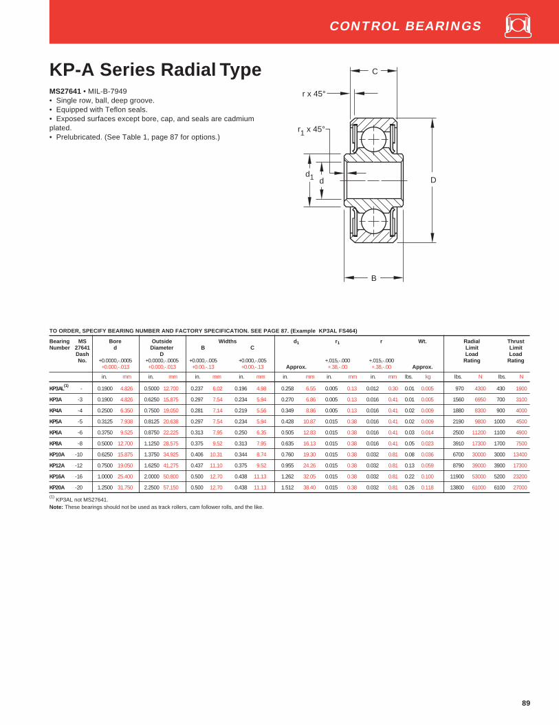
89
KP-A Series Radial TypeMS27641 • MIL-B-7949• Single row, ball, deep groove.• Equipped with Teflon seals.• Exposed surfaces except bore, cap, and seals are cadmiumplated.• Prelubricated. (See Table 1, page 87 for options.)
TO ORDER, SPECIFY BEARING NUMBER AND FACTORY SPECIFICATION. SEE PAGE 87. (Example KP3AL FS464)
Bearing MS Bore Outside Widths d 1 r1 r Wt. Radial ThrustNumber 27641 d Diameter B C Limit Limit
Dash D Load LoadNo. +0.0000,-.0005 +0.0000,-.0005 +0.000,-.005 +0.000,-.005 +.015,-.000 +.015,-.000 Rating Rating
+0.000,-.013 +0.000,-.013 +0.00,-.13 +0.00,-.13 Approx. +.38,-.00 +.38,-.00 Approx.
in. mm in. mm in. mm in. mm in. mm in. mm in. mm lbs. kg lbs. N lbs. N
KP3AL(1)
- 0.1900 4.826 0.5000 12.700 0.237 6.02 0.196 4.98 0.258 6.55 0.005 0.13 0.012 0.30 0.01 0.005 970 4300 430 1900
KP3A -3 0.1900 4.826 0.6250 15.875 0.297 7.54 0.234 5.94 0.270 6.86 0.005 0.13 0.016 0.41 0.01 0.005 1560 6950 700 3100
KP4A -4 0.2500 6.350 0.7500 19.050 0.281 7.14 0.219 5.56 0.349 8.86 0.005 0.13 0.016 0.41 0.02 0.009 1880 8300 900 4000
KP5A -5 0.3125 7.938 0.8125 20.638 0.297 7.54 0.234 5.94 0.428 10.87 0.015 0.38 0.016 0.41 0.02 0.009 2190 9800 1000 4500
KP6A -6 0.3750 9.525 0.8750 22.225 0.313 7.95 0.250 6.35 0.505 12.83 0.015 0.38 0.016 0.41 0.03 0.014 2500 11200 1100 4900
KP8A -8 0.5000 12.700 1.1250 28.575 0.375 9.52 0.313 7.95 0.635 16.13 0.015 0.38 0.016 0.41 0.05 0.023 3910 17300 1700 7500
KP10A -10 0.6250 15.875 1.3750 34.925 0.406 10.31 0.344 8.74 0.760 19.30 0.015 0.38 0.032 0.81 0.08 0.036 6700 30000 3000 13400
KP12A -12 0.7500 19.050 1.6250 41.275 0.437 11.10 0.375 9.52 0.955 24.26 0.015 0.38 0.032 0.81 0.13 0.059 8790 39000 3900 17300
KP16A -16 1.0000 25.400 2.0000 50.800 0.500 12.70 0.438 11.13 1.262 32.05 0.015 0.38 0.032 0.81 0.22 0.100 11900 53000 5200 23200
KP20A -20 1.2500 31.750 2.2500 57.150 0.500 12.70 0.438 11.13 1.512 38.40 0.015 0.38 0.032 0.81 0.26 0.118 13800 61000 6100 27000
(1) KP3AL not MS27641.
Note: These bearings should not be used as track rollers, cam follower rolls, and the like.
r x 45°
d D
r1 x 45°
C
d1
B
CONTROL BEARINGS

90
AW-AK SeriesRadial Type,Stainless SteelMS27649 • MIL-B-7949• Single row, ball, deep groove.• Rings and balls are made of 440C stainless steel (not cadmium plated).• Equipped with Teflon seals.• Prelubricated. (See Table 1, page 87 for options.)• Bores and outside diameters of this series are the same as for
corresponding sizes of the KP-A Series on Control Bearings page 9, butrings are wider for retainers and seals, and offsets between inner andouter ring faces are greater, providing increased bracket clearance atmounting.
B
r x 45°
d D
r1 x 45°
C
d1
TO ORDER, SPECIFY BEARING NUMBER AND FACTORY SPECIFICATION. SEE PAGE 87. (Example AW3AK FS464)
Bearing MS Bore Outside Widths d 1 r1 r Wt. Radial ThrustNumber 27649 d Diameter B C Limit Limit
Dash D Load LoadNo. +0.0000, -.0005 +0.0000, -.0005 +0.0000, -.0025 +0.000, -.005 +0.015, -.000 +0.015, -.000 Rating Rating
+0.000, -.013 +0.000, -.013 +0.000, -.064 +0.00, -.13 Approx. +0.38, -.00 +0.38, -.00 Approx.
in. mm in. mm in. mm in. mm in. mm in. mm in. mm lbs. kg lbs. N lbs. N
*AW3AK -3 0.1900 4.826 0.6250 15.875 0.4060 10.310 0.312 7.92 0.317 8.05 0.005 0.13 0.016 0.41 0.018 0.008 750 3350 350 1560
*AW4AK -4 0.2500 6.350 0.7500 19.050 0.4380 11.130 0.312 7.92 0.415 10.54 0.005 0.13 0.016 0.41 0.028 0.013 880 3900 410 1830
*AW5AK -5 0.3125 7.938 0.8125 20.638 0.4690 11.910 0.344 8.74 0.462 11.73 0.015 0.38 0.016 0.41 0.033 0.015 1370 6100 640 2850
*AW6AK -6 0.3750 9.525 0.8750 22.225 0.4690 11.910 0.344 8.74 0.520 13.21 0.015 0.38 0.016 0.41 0.034 0.015 1370 6100 640 2850
*AW8AK -8 0.5000 12.700 1.1250 28.575 0.5620 14.270 0.438 11.13 0.681 17.30 0.015 0.38 0.016 0.41 0.075 0.034 2250 10000 1050 4650
*AW10AK -10 0.6250 15.875 1.3750 34.925 0.5940 15.090 0.469 11.91 0.848 21.54 0.015 0.38 0.032 0.81 0.119 0.054 3060 13700 1430 6400
*AW12AK -12 0.7500 19.050 1.6250 41.275 0.6560 16.660 0.531 13.49 1.052 26.72 0.015 0.38 0.032 0.81 0.189 0.086 4000 17600 1870 8300
*AW16AK(1)
-16 1.0000 25.400 2.0000 50.800 0.6880 17.480 0.562 14.27 1.334 33.88 0.015 0.38 0.032 0.81 0.296 0.134 5000 22400 2340 10400
*AW20AK(1)
-20 1.2500 31.750 2.2500 57.150 0.6880 17.480 0.562 14.27 1.615 41.02 0.015 0.38 0.032 0.81 0.355 0.161 6000 26500 2800 12500(1)
Not in production. Will be produced as requirements justify tooling. Note: These bearings should not be used as track rollers, cam follower rolls, and the like.
* Check for availability.
CONTROL BEARINGS

91
KSP, KSP-A SeriesSelf-Aligning TypeMS27645 • MIL-B-7949• Single row, ball, self-aligning.• Equipped with bonded Teflon seals.• Exposed surfaces except bore, cap, and seals are cadmium plated.• Prelubricated. (See Table 1, page 87 for options.)• Caution: Do not allow these bearings to act as misalignment stops.
TO ORDER, SPECIFY BEARING NUMBER AND FACTORY SPECIFICATION. SEE PAGE 87. (Example KSP3L FS464)
Bearing (1) MS Bore Outside Widths d 1 r1 r Wt. Radial ThrustNumber 27645 d Diameter B C Limit Limit
Dash D Load LoadNo. +0.0000,-.0005 +0.0000,-.0005 +0.0000,-.005 +0.000,-.005 +0.015,-.000 +0.015,-.000 Rating Rating
+0.000,-.013 +0.000,-.013 +0.000,-.15 +0.00,-.13 Approx. +0.38,-.00 +0.38-.00 Approx.
in. mm in. mm in. mm in. mm in. mm in. mm in. mm lbs. kg lbs. N lbs. N
KSP3L -3A 0.1900 4.826 0.6250 15.875 0.245 6.22 0.203 5.16 0.256 6.50 0.005 0.13 0.016 0.41 0.01 0.005 550 2450 100 450
KSP4A -4A 0.2500 6.350 0.7500 19.050 0.281 7.14 0.219 5.56 0.328 8.33 0.005 0.13 0.016 0.41 0.02 0.009 900 4000 200 900
KSP5A -5A 0.3125 7.938 0.8125 20.638 0.297 7.54 0.234 5.94 0.389 9.88 0.015 0.38 0.016 0.41 0.02 0.009 1000 4400 200 900
KSP6A -6A 0.3750 9.525 0.8750 22.225 0.313 7.95 0.250 6.35 0.462 11.73 0.016 0.41 0.016 0.41 0.03 0.014 1120 5000 200 900
KSP3 -3 0.1900 4.826 0.7774 19.746 0.297 7.54 0.270 6.86 0.297 7.54 0.005 0.13 0.022 0.56 0.03 0.014 900 4000 200 900
KSP4 -4 0.2500 6.350 0.9014 22.896 0.484 12.29 0.335 8.51 0.396 10.06 0.005 0.13 0.032 0.81 0.04 0.018 1410 6300 300 1340
KSP5 -5 0.3125 7.938 1.2500 31.750 0.558 14.17 0.375 9.52 0.567 14.40 0.015 0.38 0.032 0.81 0.1 0.045 2190 9800 300 1340
KSP6 -6 0.3750 9.525 1.4375 36.512 0.620 15.75 0.469 11.91 0.612 15.54 0.015 0.38 0.032 0.81 0.15 0.068 2980 13200 400 1760
KSP8 -8 0.5000 12.700 1.6875 42.862 0.620 15.75 0.500 12.70 0.796 20.22 0.015 0.38 0.044 1.12 0.23 0.104 3670 16300 500 2240
KSP10 -10 0.6250 15.875 1.9375 49.212 0.813 20.65 0.625 15.88 0.922 23.42 0.015 0.38 0.044 1.12 0.37 0.168 5320 23600 600 2650(1)
These bearings are self-aligning for 10° in either direction except KSP4A, KSP5A and KSP6A which are self aligning for 8° in either direction.
Note: These bearings should not be used as track rollers, cam follower rolls, and the like.
*Check for availability.
CONTROL BEARINGS
C
d D
r x 45°
r1 x 45°
d1
B
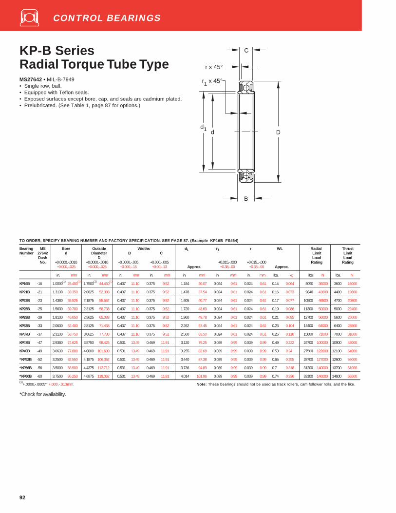
92
KP-B SeriesRadial Torque Tube TypeMS27642 • MIL-B-7949• Single row, ball.• Equipped with Teflon seals.• Exposed surfaces except bore, cap, and seals are cadmium plated.• Prelubricated. (See Table 1, page 87 for options.)
d D
B
C
d1
r x 45°
r1 x 45°
TO ORDER, SPECIFY BEARING NUMBER AND FACTORY SPECIFICATION. SEE PAGE 87. (Example KP16B FS464)
Bearing MS Bore Outside Widths d 1 r1 r Wt. Radial ThrustNumber 27642 d Diameter B C Limit Limit
Dash D Load LoadNo. +0.0000,-.0010 +0.0000,-.0010 +0.0000,-.005 +0.000,-.005 +0.015,-.000 +0.015.,-.000 Rating Rating
+0.000,-.025 +0.000,-.025 +0.000,-.15 +0.00,-.13 Approx. +0.38,-.00 +0.38,-.00 Approx.
in. mm in. mm in. mm in. mm in. mm in. mm in. mm lbs. kg lbs. N lbs. N
KP16B -16 1.0000(1)
25.400(1)
1.7500(1)
44.450(1)
0.437 11.10 0.375 9.52 1.184 30.07 0.024 0.61 0.024 0.61 0.14 0.064 8090 36000 3600 16000
KP21B -21 1.3130 33.350 2.0625 52.388 0.437 11.10 0.375 9.52 1.478 37.54 0.024 0.61 0.024 0.61 0.16 0.073 9840 43000 4400 19600
KP23B -23 1.4380 36.525 2.1875 55.562 0.437 11.10 0.375 9.52 1.605 40.77 0.024 0.61 0.024 0.61 0.17 0.077 10500 46500 4700 20800
KP25B -25 1.5630 39.700 2.3125 58.738 0.437 11.10 0.375 9.52 1.720 43.69 0.024 0.61 0.024 0.61 0.19 0.086 11300 50000 5000 22400
KP29B -29 1.8130 46.050 2.5625 65.088 0.437 11.10 0.375 9.52 1.960 49.78 0.024 0.61 0.024 0.61 0.21 0.095 12700 56000 5600 25000
KP33B -33 2.0630 52.400 2.8125 71.438 0.437 11.10 0.375 9.52 2.262 57.45 0.024 0.61 0.024 0.61 0.23 0.104 14400 64000 6400 28500
KP37B -37 2.3130 58.750 3.0625 77.788 0.437 11.10 0.375 9.52 2.500 63.50 0.024 0.61 0.024 0.61 0.26 0.118 15800 71000 7000 31000
KP47B -47 2.9380 74.625 3.8750 98.425 0.531 13.49 0.469 11.91 3.120 79.25 0.039 0.99 0.039 0.99 0.49 0.222 24700 100000 10900 48000
KP49B -49 3.0630 77.800 4.0000 101.600 0.531 13.49 0.469 11.91 3.255 82.68 0.039 0.99 0.039 0.99 0.53 0.24 27500 122000 12100 54000
*KP52B -52 3.2500 82.550 4.1875 106.362 0.531 13.49 0.469 11.91 3.440 87.38 0.039 0.99 0.039 0.99 0.65 0.295 28700 127000 12600 56000
*KP56B -56 3.5000 88.900 4.4375 112.712 0.531 13.49 0.469 11.91 3.736 94.89 0.039 0.99 0.039 0.99 0.7 0.318 31200 140000 13700 61000
*KP60B -60 3.7500 95.250 4.6875 119.062 0.531 13.49 0.469 11.91 4.014 101.96 0.039 0.99 0.039 0.99 0.74 0.336 33100 146000 14600 65500(1)
+.0000,-.0005"; +.000,-.013mm.
*Check for availability.
Note: These bearings should not be used as track rollers, cam follower rolls, and the like.
CONTROL BEARINGS

93
KP-BS SeriesSelf-AligningTorque Tube TypeMS27648 • MIL-B-7949• Single row, ball, external self aligning.• Equipped with Teflon seals.• Exposed surfaces except bore, cap, and seals are cadmium plated.• Prelubricated. (See Table 1, page 87 for options.)• Series is internally identical to the KP-B series. Self-alignment is
provided by an external self-aligning ring whose internal spherically-ground surface is accurately matched to the external spherically-ground surface of the outer ring. These bearings are designed tocompensate for initial misalignment.
C
d D
B
r x 45°
r1 x 45°
d1D1
TO ORDER, SPECIFY BEARING NUMBER AND FACTORY SPECIFICATION. SEE PAGE 87. (Example KP16BS FS464)
Brg. MS Bore Outside Widths d 1 r1 r D1 ∆ Wt. Radial ThrustNo. 27648 d Diameter B C To Mis- Limit Limit
Dash D Sharp alignment Load LoadNo. +0.0000,-.0010 +0.0000,-.0010 +0.0000,-.005 +0.000,-.005 +0.015,-.000 +0.015,-.000 Corner Either Rating Rating
+0.000,-.025 +0.000,-.025 +0.000,-.13 +0.00,-.13 Approx. +0.38,-.00 +0.38,-.00 (Ref.) Direction Approx.
in. mm in. mm in. mm in. mm in. mm in. mm in. mm in. mm lbs. kg lbs. N lbs. N
KP16BS -16 1.0000(1)
25.400(1)
1.9375 49.212 0.437 11.10 0.375 9.52 1.184 30.70 0.024 0.61 0.024 0.61 1.709 43.41 7°25' 0.18 0.082 8090 36000 1600 7100
KP21BS -21 1.3130 33.350 2.2500 57.150 0.437 11.10 0.375 9.52 1.478 37.54 0.024 0.61 0.024 0.61 2.028 51.51 6°30' 0.2 0.091 9840 43000 2000 9000
KP23BS -23 1.4380 36.525 2.3750 60.325 0.437 11.10 0.375 9.52 1.605 40.77 0.024 0.61 0.024 0.61 2.155 54.74 6° 0.22 0.1 10500 46500 2200 9800
KP25BS -25 1.5630 39.700 2.5000 63.500 0.437 11.10 0.375 9.52 1.720 43.69 0.024 0.61 0.024 0.61 2.282 57.96 5°45' 0.25 0.113 11300 50000 2300 10200
KP29BS -29 1.8130 46.050 2.7500 69.850 0.437 11.10 0.375 9.52 1.960 49.78 0.024 0.61 0.024 0.61 2.535 64.39 5° 0.27 0.122 12700 56000 2600 11600
KP33BS -33 2.0630 52.400 3.0000 76.200 0.437 11.10 0.375 9.52 2.262 57.45 0.024 0.61 0.024 0.61 2.787 70.79 5° 0.3 0.136 14400 64000 2900 12900
KP37BS -37 2.3130 58.750 3.2500 82.550 0.437 11.10 0.375 9.52 2.500 63.50 0.024 0.61 0.024 0.61 3.039 77.19 4°30' 0.33 0.15 15800 71000 3200 14300
KP47BS -47 2.9380 74.625 4.1250 104.775 0.531 13.49 0.469 11.91 3.120 79.25 0.039 0.99 0.039 0.99 3.846 97.69 4°30' 0.64 0.29 24700 100000 5000 22400
*KP48BS -48 3.0000 76.200 4.2500 107.950 0.531 13.49 0.469 11.91 3.255 82.68 0.039 0.99 0.039 0.99 3.972 100.89 4° 0.69 0.313 27500 122000 5500 24500
KP49BS -49 3.0625 77.788 4.2500 107.950 0.531 13.49 0.469 11.91 3.255 82.68 0.039 0.99 0.039 0.99 3.972 100.89 4° 0.69 0.313 27500 122000 5500 24500
(1 ) +.0000" (.000mm), -.0005" (.013mm)
Note: These bearings should not be used as track rollers, cam follower rolls, and the like.
*Check for availability.
CONTROL BEARINGS
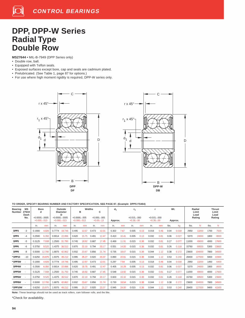
94
DPP, DPP-W SeriesRadial TypeDouble RowMS27644 • MIL-B-7949 (DPP Series only)• Double row, ball.• Equipped with Teflon seals.• Exposed surfaces except bore, cap and seals are cadmium plated.• Prelubricated. (See Table 1, page 87 for options.)• For use where high moment rigidity is required, DPP-W series only.
TO ORDER, SPECIFY BEARING NUMBER AND FACTORY SPECIFICATION. SEE PAGE 87. (Example DPPS FS464)
Bearing MS Bore Outside Widths d 1 r1 r Wt. Radial ThrustNumber 27644 d Diameter B C Limit Limit
Dash D Load LoadNo. +0.0000,-.0005 +0.0000,-.0005 +0.0000,-.005 +0.000,-.005 +0.015,-.000 +0.015,-.000 Rating Rating
+0.000,-.013 +0.000,-.013 +0.000,-.013 +0.00,-.13 Approx. +0.38,-.00 +0.38,-.00 Approx.
in. mm in. mm in. mm in. mm in. mm in. mm in. mm lbs. kg lbs. N lbs. N
DPP3 -3 0.1900 4.826 0.7774 19.746 0.495 12.57 0.473 12.01 0.302 7.67 0.005 0.13 0.018 0.46 0.04 0.018 2950 13200 1700 7500
DPP4 -4 0.2500 6.350 0.9014 22.896 0.620 15.75 0.491 12.47 0.410 10.41 0.005 0.13 0.032 0.81 0.06 0.027 5370 24000 1800 8000
DPP5 -5 0.3125 7.938 1.2500 31.750 0.745 18.92 0.687 17.45 0.469 11.91 0.015 0.38 0.032 0.81 0.17 0.077 11000 49000 4000 17600
DPP6 -6 0.3750 9.525 1.4375 36.512 0.870 22.10 0.794 20.17 0.551 14.00 0.015 0.38 0.032 0.81 0.26 0.118 15760 69500 5300 23600
DPP8 -8 0.5000 12.700 1.6875 42.862 0.932 23.67 0.856 21.74 0.735 18.67 0.015 0.38 0.044 1.12 0.38 0.172 23600 104000 7800 34500
*DPP10 -10 0.6250 15.875 1.9375 49.212 0.995 25.27 0.920 23.37 0.890 22.61 0.015 0.38 0.044 1.12 0.53 0.240 28400 127000 9400 41500
*DPP3W - 0.1900 4.826 0.7774 19.746 0.495 12.57 0.473 12.01 0.297 7.54 0.005 0.13 0.018 0.46 0.04 0.018 2950 13200 1450 6400
DPP4W - 0.2500 6.350 0.9014 22.896 0.620 15.75 0.491 12.47 0.405 10.29 0.005 0.13 0.032 0.81 0.06 0.027 5370 24000 1800 8000
DPP5W - 0.3125 7.938 1.2500 31.750 0.745 18.92 0.687 17.45 0.548 13.92 0.015 0.38 0.032 0.81 0.17 0.077 11000 49000 4000 17600
DPP6W - 0.3750 9.525 1.4375 36.512 0.870 22.10 0.794 20.17 0.603 15.32 0.015 0.38 0.032 0.81 0.26 0.118 15760 69500 5300 23600
DPP8W - 0.5000 12.700 1.6875 42.862 0.932 23.67 0.856 21.74 0.730 18.54 0.015 0.38 0.044 1.12 0.38 0.172 23600 104000 7800 34500
*DPP10W - 0.6250 15.875 1.9375 49.212 0.995 25.27 0.920 23.37 0.945 24.00 0.015 0.38 0.044 1.12 0.53 0.240 28400 127000 9400 41500
Note: These bearings should not be used as track rollers, cam follower rolls, and the like.
*Check for availability.
d D
C
r x 45°
r1 x 45°
d1
B
d D
C
r x 45°
r1 x 45°
d1
BDPP DPP-WDF DB
CONTROL BEARINGS

95
DSP SeriesSelf-Aligning TypeDouble RowMS27643 • MIL–B–7949• Double row, ball, self-aligning.• Equipped with Teflon seals.• Exposed surfaces except bore, cap, and seals are cadmium plated.• Prelubricated. (See Table 1, page 87 for options.)
TO ORDER, SPECIFY BEARING NUMBER AND FACTORY SPECIFICATION. SEE PAGE 87. (Example DSP3 FS464)
Bearing MS Bore Outside Widths d 1 r1 r Wt. Radial Thrust No.(1) 27643 d Diameter B C Limit Limit
Dash D Load LoadNo. +0.0000,-.0005 +0.0000,-.0005 +0.0000,-.005 +0.000,-.005 +0.015,-.000 +0.015,-.000 Rating Rating
+0.000,-.013 +0.000,-.013 +0.000,-.13 +0.00,-.13 Approx. +0.38,-.00 +0.38,-.00 Approx.
in. mm in. mm in. mm in. mm in. mm in. mm in. mm lbs. kg lbs. N lbs. N
DSP3 -3 0.1900 4.826 0.7774 19.746 0.500 12.70 0.392 9.96 0.304 7.72 0.005 0.13 0.022 0.56 0.04 0.018 1420 6400 200 900
DSP4 -4 0.2500 6.350 0.9014 22.896 0.687 17.45 0.464 11.79 0.430 10.92 0.005 0.13 0.032 0.81 0.06 0.027 1780 8000 300 1340
DSP5 -5 0.3125 7.938 1.2500 31.750 0.812 20.62 0.656 16.66 0.515 13.08 0.015 0.38 0.032 0.81 0.16 0.073 3740 16600 600 2650
DSP6 -6 0.3750 9.525 1.4375 36.512 0.937 23.80 0.750 19.05 0.564 14.33 0.015 0.38 0.032 0.81 0.24 0.109 5100 22800 800 3550
DSP8 -8 0.5000 12.700 1.6875 42.862 1.000 25.40 0.812 20.62 0.775 19.68 0.015 0.38 0.044 1.12 0.36 0.163 7120 31500 1000 4400
DSP10 -10 0.6250 15.875 1.9375 49.212 1.125 28.58 0.937 23.8 0.869 22.07 0.015 0.38 0.044 1.12 0.53 0.240 9000 40000 1300 5850
(1) These bearings are self-aligning for 10° in either direction .
Note: These bearings should not be used as track rollers, cam follower rolls, and the like.
B
C
d D
r x 45°
r1 x 45°
d1
CONTROL BEARINGS

96
DSRP, GDSRP SeriesSelf-Aligning Type Roller• Exposed surfaces except bore, cap, and seals are cadmium plated.• Prelubricated. (See Table 1, page 87 for options.)• The DSRP series is dimensionally interchangeable with the DSP
series except the DSRP4 inner ring width and shoulder.• Equipped with Teflon seals.
• The GDSRP series is dimensionally interchangeable with the DSRPseries; however, it is relubricable through grooves and holes drilledoutside of the bearing load zone, which permits access of lubricant torollers and raceways.
• Caution: Do not allow these bearings to act as misalignment stops.
TO ORDER, SPECIFY BEARING NUMBER AND FACTORY SPECIFICATION. SEE PAGE 87. (Example DSRP4 FS464)
Bearing Bore Outside Widths d 1 r1 r Rollers Wt. RadialNumber (1) d Diameter B C Limit
D LoadDSRP GDSRP +0.0000,-.0005 +0.0000,-.0005 +0.000,-.005 +0.000,-.005 +0.015,-.000 +0.015,-.000 Rating (3)
Series Series +0.000,-.013 +0.000,-.013 +0.00,-.13 +0.00,-.13 Approx. +0.38,-.00 +0.38,-.00 No. Dia. Approx
in. mm in. mm in. mm in. mm in. mm in. mm in. mm in. mm lbs. kg lbs. N
DSRP4 GDSRP4 0.2500 6.350 0.9014 22.896 0.625 15.88 0.464 11.78 0.404 10.26 0.005 0.13 0.032 0.81 12 0.1514 3.846 0.06 0.027 3025 13400
DSRP5 GDSRP5 0.3125 7.938 1.2500 31.750 0.812 20.62 0.656 16.66 0.515 13.08 0.015 0.38 0.032 0.81 11 0.2303 5.850 0.16 0.073 7350 32500
DSRP6 GDSRP6 0.3750 9.525 1.4375 36.512 0.937 23.80 0.750 19.05 0.564 14.33 0.015 0.38 0.032 0.81 11 0.2681 6.810 0.24 0.109 9600 42500
DSRP8 GDSRP8 0.5000 12.700 1.6875 42.862 1.000 25.40 0.812 20.62 0.775 19.68 0.015 0.38 0.044 1.12 12 0.3023 7.678 0.36 0.163 12500 56000
*DSRP10 GDSRP10(2)
0.6250 15.875 1.9375 49.212 1.125 28.58 0.937 23.80 0.869 22.07 0.015 0.38 0.044 1.12 14 0.3016 7.661 0.55 0.249 17700 78000
*DSRP12 GDSRP12(2)
0.7500 19.050 2.3750 60.325 1.312 33.32 1.125 28.58 1.150 29.21 0.015 0.38 0.044 1.12 13 0.3900 9.906 1.05 0.476 26900 120000(1)
These bearings are self-aligning for 10° in either direction .(2)
Will be made as demand justifies tooling.(3)
Thrust limit load rating = 30% of the radial limit load rating.
Note: These bearings should not be used as track rollers, cam follower rolls, and the like.
*Check for availability.
B
C
d D
r x 45°
r1 x 45°
d1 d D
RELUBRICATIONFEATURE
C
r x 45°
r1 x 45°
d1
B
DSRP GDSRP
CONTROL BEARINGS

97
d D
C
r
r1
d1
B
Bearing Bore Outside Widths d 1 r1(3) r(3) Wt. Radial Thrust
Number d Diameter B C Limit LimitD Load Load
+0.0007,-.0007 +0.0000,-.0010 +0.000,-.005 +0.000,-.005 Rating Rating+0.018,-.018 +0.000,-.025 +0.00,-.13 +0.00,-.13 Approx. Approx.
in. mm in. mm in. mm in. mm in. mm in. mm in. mm lbs. kg lbs. N lbs. N
B538 0.6250 15.875 1.0625 26.988 0.281 7.14 0.250 6.35 0.777 19.74 0.015 0.38 0.015 0.38 0.02 0.009 3280 14600 1500 6700
B539 0.7500 19.050 1.1875 30.162 0.281 7.14 0.250 6.35 0.895 22.73 0.015 0.38 0.015 0.38 0.03 0.014 3750 16600 1700 7500
B540 0.8750 22.225 1.3125 33.338 0.281 7.14 0.250 6.35 1.016 25.81 0.015 0.38 0.015 0.38 0.04 0.018 4220 18600 1900 8500
B541 1.0625 26.988 1.5000 38.100 0.281 7.14 0.250 6.35 1.216 30.89 0.015 0.38 0.015 0.38 0.05 0.023 5000 22400 2200 9800
B542 1.3125 33.338 1.7500 44.450 0.281 7.14 0.250 6.35 1.451 36.86 0.015 0.38 0.015 0.38 0.07 0.032 5950 26500 2700 12000
B543 1.5625 39.688 2.0000 50.800 0.281 7.14 0.250 6.35 1.702 43.23 0.015 0.38 0.015 0.38 0.08 0.036 6880 30500 3200 14300
B544 1.8125(1)
46.038(1)
2.2500(2)
57.150(2)
0.281 7.14 0.250 6.35 1.970 50.04 0.015 0.38 0.015 0.38 0.09 0.041 7980 35500 3600 16000
B545 2.0625(1)
52.388(1)
2.6250(2)
66.675(2)
0.281 7.14 0.250 6.35 2.286 58.06 0.015 0.38 0.015 0.38 0.13 0.059 9220 41500 4000 17600
B546 2.3125(1)
58.738(1)
2.8750(2)
73.025(2)
0.281 7.14 0.250 6.35 2.527 64.19 0.015 0.38 0.015 0.38 0.15 0.068 10150 45500 4400 19600
(1) +.0010" (+.025mm), -.0010" (-.025mm).
(2) +.0000" (+.000mm), -.0015" (-.038mm).
(3) Maximum shaft or housing fillet radius which bearing corners will clear.
Note: These bearings should not be used as track rollers, cam follower rolls, and the like.
*Check for availability.
B500 SeriesExtra LightTorque Tube Type• Extra light duty.• Single row, ball.• This series is made of bearing quality chromium-alloy, high carbon
steel and is not cadmium plated.• Open type - no seals or shields.• Prepacked with a preservative.
CONTROL BEARINGS

98
B500DD SeriesExtra LightTorque Tube TypeMS27646 • MIL-B-7949• Extra light duty.• Single row, ball.• Teflon coated glass fabric shields.• Exposed surfaces except bore, cap, and shields are cadmium plated.• Prelubricated. (See Table 1, page 87 for options.)• This series is dimentionally interchangeable with the unshielded B500 series.
C
d D
B
r x 45°
r1 x 45°
d1
TO ORDER, SPECIFY BEARING NUMBER AND FACTORY SPECIFICATION. SEE PAGE 87. (Example B538DD FS464)
Bearing MS Bore Outside Widths d 1 r1(3)
r(3)
Wt. Radial ThrustNumber 27646 d Diameter B C Limit Limit
Dash D Load Load No. +0.0007,-.0007 +0.0000-.0010 +0.000,-.005 +0.000,-.005 Rating Rating
+0.018,-.018 +0.000,-.025 +0.00,-.13 +0.00,-.13 Approx. Approx.
in. mm in. mm in. mm in. mm in. mm in. mm in. mm lbs. kg lbs. N lbs. N
B538DD -38 0.6250 15.875 1.0625 26.988 0.281 7.14 0.250 6.35 0.777 19.74 0.015 0.38 0.015 0.38 0.03 0.014 3280 14600 1500 6700
B539DD -39 0.7500 19.050 1.1875 30.162 0.281 7.14 0.250 6.35 0.895 22.73 0.015 0.38 0.015 0.38 0.04 0.018 3750 16600 1700 7500
B540DD -40 0.8750 22.225 1.3125 33.338 0.281 7.14 0.250 6.35 1.016 25.81 0.015 0.38 0.015 0.38 0.05 0.023 4220 18600 1900 8500
B541DD -41 1.0625 26.988 1.5000 38.100 0.281 7.14 0.250 6.35 1.216 30.89 0.015 0.38 0.015 0.38 0.06 0.027 5000 22400 2200 9800
B542DD -42 1.3125 33.338 1.7500 44.450 0.281 7.14 0.250 6.35 1.451 36.86 0.015 0.38 0.015 0.38 0.09 0.041 5950 26500 2700 12000
B543DD -43 1.5625 39.688 2.0000 50.800 0.281 7.14 0.250 6.35 1.702 43.23 0.015 0.38 0.015 0.38 0.10 0.045 6880 30500 3200 14300
B544DD -44 1.8125(1) 46.038(1) 2.2500(2) 57.150(2) 0.281 7.14 0.250 6.35 1.970 50.04 0.015 0.38 0.015 0.38 0.11 0.050 7980 35500 3600 16000
B545DD -45 2.0625(1) 52.388(1) 2.6250(2) 66.675(2) 0.281 7.14 0.250 6.35 2.286 58.06 0.015 0.38 0.015 0.38 0.15 0.068 9220 41500 4000 17600
B546DD -46 2.3125(1) 58.738(1) 2.8750(2) 73.025(2) 0.281 7.14 0.250 6.35 2.527 64.19 0.015 0.38 0.015 0.38 0.17 0.077 10150 45500 4400 19600
(1) +.0010" (+.025mm), -.0010" (-.025mm).
(2) +.0000" (+.000mm), -.0015" (-.038mm).
(3) Maximum shaft or housing fillet radius which bearing corners will clear.
Note: These bearings should not be used as track rollers, cam follower rolls, and the like.
*Check for availability.
CONTROL BEARINGS

99
TO ORDER, SPECIFY BEARING NUMBER AND FACTORY SPECIFICATION. SEE PAGE 87. (Example B5538WZZ FS464)
Bearing Bore Outside Widths d 1 r1(3) r (3) Wt. Radial Thrust
Number d Diameter B C Limit LimitD Load Load
+0.0000,-.0005 +0.0000-.0005 +0.000,-.005 +0.000-.005 Rating Rating+0.000,-.013 +0.000,-.013 +0.00,-.13 +0.00,-.13 Approx. Approx.
in. mm in. mm in. mm in. mm in. mm in. mm in. mm lbs. kg lbs. N lbs. N
B5538WZZ 0.6250 15.875 1.0625 26.988 0.562 14.27 0.500 12.70 0.745 18.92 0.015 0.38 0.015 0.38 0.04 0.018 6250 28000 2060 9150
B5539WZZ 0.7500 19.050 1.1875 30.162 0.562 14.27 0.500 12.70 0.865 21.97 0.015 0.38 0.015 0.38 0.06 0.027 7190 32000 2370 10600
B5540WZZ 0.8750 22.225 1.3125 33.338 0.562 14.27 0.500 12.70 0.989 25.12 0.015 0.38 0.015 0.38 0.08 0.036 8120 36000 2680 12000
B5541WZZ 1.0625 26.988 1.5000 38.100 0.562 14.27 0.500 12.70 1.190 30.23 0.015 0.38 0.015 0.38 0.1 0.045 9690 43000 3200 14300
B5542WZZ 1.3125 33.338 1.7500 44.450 0.562 14.27 0.500 12.70 1.430 36.32 0.015 0.38 0.015 0.38 0.14 0.064 11600 52000 3820 17000
B5543WZZ 1.5625 39.688 2.0000 50.800 0.562 14.27 0.500 12.70 1.665 42.29 0.015 0.38 0.015 0.38 0.16 0.073 13400 60000 4430 19600
B5544WZZ 1.8125(1)
46.038(1)
2.2500(2)
57.150(2)
0.562 14.27 0.500 12.70 1.935 49.15 0.015 0.38 0.015 0.38 0.18 0.082 15600 69500 5160 22800
B5545WZZ 2.0625(1)
52.388(1)
2.6250(2)
66.675(2)
0.562 14.27 0.500 12.70 2.265 57.53 0.015 0.38 0.015 0.38 0.26 0.118 18100 80000 5980 26500
*B5546WZZ 2.3125(1)
58.738(1)
2.8750(2)
73.025(2)
0.562 14.27 0.500 12.70 2.505 63.63 0.015 0.38 0.015 0.38 0.3 0.136 20000 90000 6600 29000
(1) +.0000" (+.000mm), -.0008" (-.020mm).
(2) +.0000" (+.000mm), -.0007" (-.018mm).
*Check for availability.
(3) Maximum shaft or housing fillet radius which bearing corners will clear.
Note: These bearings should not be used as track rollers, cam follower rolls, and the like.
C
d D
B
d1
r x 45°
r1 x 45°
B5500WZZ SeriesDouble RowTorque Tube Type• Extra light duty.• Double row, ball.• Torque tube type.• Teflon coated glass fabric seals.• Exposed surfaces except bore, cap, and seals are cadmium plated.• Prelubricated. (See Table 1, page 87 for options.)
CONTROL BEARINGS
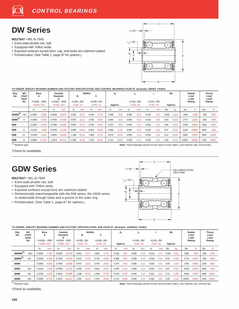
100
DW SeriesMS27647 • MIL-B-7949• Extra wide,double row, ball.• Equipped with Teflon seals.• Exposed surfaces except bore, cap, and seals are cadmium plated.• Prelubricated. (See Table 1, page 87 for options.)
B
C
d D
r x 45°
r1 x 45°
d1
TO ORDER, SPECIFY BEARING NUMBER AND FACTORY SPECIFICATION. SEE CONTROL BEARINGS PAGE 87. (Example DW4K2 FS464)
Brg. MS Bore Outside Widths d 1 r1 r Wt. Radial ThrustNo. 27647 d Diameter B C Limit Limit
Dash D Load LoadNo. +0.0000, -.0005 +0.0000, -.0005 +0.000,-.005 +0.000,-.005 +0.015,-.000 +0.015,-.000 Rating Rating
+0.000,-.013 +0.000,-.013 +0.00,-.13 +0.00,-.13 Approx. +0.38,-.00 +0.38,-.00 Approx.
in. mm in. mm in. mm in. mm in. mm in. mm in. mm lbs. kg lbs. N lbs. N
DW4K2(1)
–4A 0.2500 6.350 0.6250 15.875 0.562 14.27 0.500 12.70 0.339 8.61 0.005 0.13 0.016 0.41 0.025 0.011 1400 6200 500 2240
DW4K(1)
–4 0.2500 6.350 0.7500 19.050 0.875 22.22 0.750 19.05 0.380 9.65 0.005 0.13 0.016 0.41 0.04 0.018 2770 12200 900 4000
DW4 – 0.2500 6.350 0.7500 19.050 0.875 22.22 0.750 19.05 0.375 9.52 0.005 0.13 0.016 0.41 0.06 0.027 3750 16600 1240 5500
DW5 –5 0.3125 7.938 0.8750 22.225 0.938 23.83 0.813 20.65 0.469 11.91 0.005 0.13 0.016 0.41 0.07 0.032 5140 22800 1600 7100
DW6 –6 0.3750 9.525 1.0625 26.988 1.188 30.18 1.063 27.00 0.573 14.55 0.005 0.13 0.016 0.41 0.12 0.054 8440 37500 2600 11600
DW8 –8 0.5000 12.700 1.4375 36.512 1.500 38.10 1.375 34.92 0.712 18.08 0.005 0.13 0.032 0.81 0.29 0.132 15520 69500 4700 20800(1)
Retainer type. Note: These bearings should not be used as track rollers, cam follower rolls, and the like.
*Check for availability.
GDW SeriesMS27647 • MIL-B-7949• Extra wide,double row, ball.• Equipped with Teflon seals.• Exposed surfaces except bore are cadmium plated.• Dimensionally interchangeable with the DW series, the GDW series
is relubricable through holes and a groove in the outer ring.• Prelubricated. (See Table 1, page 87 for options.)
TO ORDER, SPECIFY BEARING NUMBER AND FACTORY SPECIFICATION. SEE PAGE 87. (Example GDW4K2 FS464)
Brg. MS Bore Outside Widths d 1 r1 r Wt. Radial ThrustNo. 27647 d Diameter B C Limit Limit
Dash D Load LoadNo. +0.0000, -.0005 +0.0000, -.0005 +0.000,-.005 +0.000,-.005 +0.015,-.000 +0.015,-.000 Rating Rating
+0.000,-.013 +0.000,-.013 +0.00,-.13 +0.00,-.13 Approx. +0.38,-.00 +0.38,-.00 Approx.
in. mm in. mm in. mm in. mm in. mm in. mm in. mm lbs. kg lbs. N lbs. N
GDW4K2(1)
–4AG 0.2500 6.350 0.6250 15.875 0.562 14.27 0.500 12.70 0.339 8.61 0.005 0.13 0.016 0.41 0.025 0.011 1400 6200 500 2240
GDW4K(1)
–4G 0.2500 6.350 0.7500 19.050 0.875 22.22 0.750 19.05 0.380 9.65 0.005 0.13 0.016 0.41 0.04 0.018 2770 12200 900 4000
GDW4 – 0.2500 6.350 0.7500 19.050 0.875 22.22 0.750 19.05 0.375 9.52 0.005 0.13 0.016 0.41 0.06 0.027 3750 16600 1240 5500
GDW5 –5G 0.3125 7.938 0.8750 22.225 0.938 23.83 0.813 20.65 0.469 11.91 0.005 0.13 0.016 0.41 0.07 0.032 5140 22800 1600 7100
GDW6 –6G 0.3750 9.525 1.0625 26.988 1.188 30.18 1.063 27.00 0.573 14.55 0.005 0.13 0.016 0.41 0.12 0.054 8440 37500 2600 11600
GDW8 –8G 0.5000 12.700 1.4375 36.512 1.500 38.10 1.375 34.92 0.712 18.08 0.005 0.13 0.032 0.81 0.29 0.132 15520 69500 4700 20800(1)
Retainer type. Note: These bearings should not be used as track rollers, cam follower rolls, and the like.
*Check for availability.
d D
B
C
r x 45°
r1 x 45°
d1
RELUBRICATIONFEATURE
CONTROL BEARINGS

101
Bearing Bore Outside Widths d 1 r1 D1 R Max. Wt.Number d Diameter B C Safe
D Working+0.000 -.010 +0.000 -.005 +0.000 -.005 +0.015 -.000 Load
+0.00 -.25 +0.00 -.13 +0.00 -.13 Approx. +0.38 -.00 Radial(1)
Approx.
in. mm in. mm in. mm in. mm in. mm in. mm in. mm in. mm lbs. N lbs. kg
*GD5M28 0.3125 7.938 1.015 25.78 0.9375 23.81 0.812 20.62 0.472 11.99 0.005 0.13 0.901 22.89 0.895 22.73 600 2650 0.1 0.0450.3120 7.925 0.900 22.86 0.905 22.99
(1) The maximum safe working load is that radial load to obtain 100,000 feet (30,500 M) peripheral travel life.
* Check for availability.
G Series• Single and double row.• Equipped with Buna N rubber seals or stainless steel shields as
indicated below.• Exposed surfaces except bore, cap, and seals are cadmium plated.• Prepacked with lubricant.
BCP Series• Double row, ball.• Equipped with Buna N rubber seals.• Exposed surfaces except bore, cap, and seals are cadmium plated.• Prepacked with lubricant conforming to MIL-G-23827
Bearing Bore Flange Widths d 1 D1 D2 Wt. Radial Thrust Number
(1)d Outside B C Limit Limit
Diameter Load LoadD Rating Rating
+0.0000 -.0005 ±.010 +0.000 -.005 ±.005 ±.010 ±.005+0.000 -.013 ±.25 +0.00 -.13 ±.13 Approx. ±.25 ±.13 Approx.
in. mm in. mm in. mm in. mm in. mm in. mm in. mm lbs. kg lbs. N lbs. N
BCP4W10 FS302 0.25 6.350 1.625 41.28 0.625 15.88 0.500 12.70 0.404 10.26 0.750 19.05 1.312 33.32 0.06 0.027 2770 12200 700 3100
BCP5W11 FS302 0.3125 7.938 1.687 42.85 0.687 17.45 0.562 14.27 0.453 11.51 0.875 22.22 1.375 34.92 0.08 0.036 3280 14600 900 4000(1)
Both sizes are furnished with 12 equally spaced holes in the flange. Holes are .140 (+.005,-.000) inches in diameter.
CONTROL BEARINGS
B
C
d D
R
d1D1
r1 x 45°
B
C
Dd
1/16R ( 1.59mm )
1/16 ( 1.59mm )
d1
D1D2

102
P Series• Equipped with Teflon seals.• Exposed surfaces except bore, cap, and seals are cadmium plated.• Prelubricated. (See Table 1, page 87 for options.)• Retainer type (except P8).• For MIL-P-7034 Pulleys.
B
C
d D
r x 45°
r1 x 45°
d1
P4K,P5K,P10K PD5K
Dd
B
C
r x 45°
r1 x 45°
d1 Dd
B
C
r x 45°
r1 x 45°
d1
P8
TO ORDER, SPECIFY BEARING NUMBER AND FACTORY SPECIFICATION. SEE PAGE 87. (Example P4K FS464)
Bearing Bore Outside Widths d 1 r1 r Wt. Radial ThrustNumber d Diameter B C Limit Limit
D Load Load+0.0000,-.0005 +0.0000,-.0005 +0.000,-.005 +0.000,-.005 +0.015,-.000 +0.015,-.000 Rating Rating+0.000,-.013 +0.000,-.013 +0.00,-.13 +0.00,-.13 Approx. +0.38,-.00 +0.38,-.00 Approx.
in. mm in. mm in. mm in. mm in. mm in. mm in. mm lbs. kg lbs. N lbs. N
P4K 0.2500 6.350 0.8750 22.225 0.438 11.13 0.375 9.52 0.423 10.74 0.005 0.13 0.022 0.56 0.04 0.018 1710 7650 800 3550
P5K 0.3125 7.938 0.8750 22.225 0.625 15.88 0.375 9.52 0.455 11.56 0.005 0.13 0.022 0.56 0.04 0.018 1710 7650 800 3550
PD5K 0.3125 7.938 0.9375 23.812 0.625 15.88 0.563 14.30 0.455 11.56 0.005 0.13 0.022 0.56 0.07 0.032 3420 15300 1030 4550
` P8(1)
0.5000 12.700 1.6875 42.862 0.750 19.05 0.563 14.30 0.768 19.51 0.005 0.13 0.032 0.81 0.24 0.109 11800 52000 5200 23200
P10K 0.6250 15.875 1.1875 30.162 0.438 11.13 0.375 9.52 0.769 19.53 0.005 0.13 0.022 0.56 0.06 0.027 2440 10800 1100 4900(1)
Full type - No retainer . Note: Although the P Series bearings are designed for use in pulleys, they are well suited foruse in other airframe applications. However these bearings should not be used as trackrollers, cam follower rolls, and the like.
*Check for availability.
CONTROL BEARINGS

103
P Series• Equipped with Teflon seals.• Exposed surfaces except bore, cap, and seals are cadmium plated.• Prelubricated. (See Table 1, page 87 for options.)• Retainer type.• For MIL-P-7034 Pulleys.
TO ORDER, SPECIFY BEARING NUMBER AND FACTORY SPECIFICATION. SEE PAGE 87. (Example P4K FS464)
Bearing Bore Outside Widths d 1 r1 r Wt. Radial ThrustNumber d Diameter B C Limit Limit
D Load Load+0.0000,-.0005 +0.0000,-.0005 +0.000,-.005 +0.000,-.005 +0.015,-.000 +0.015,-.000 Rating Rating
+0.000,-.013 +0.000,-.013 +0.00,-.13 +0.00,-.13 Approx. +0.38,-.00 +0.38,-.00 Approx.
in. mm in. mm in. mm in. mm in. mm in. mm in. mm lbs. kg lbs. N lbs. N
*KP3K 0.1900 4.826 0.7774 19.746 0.297 7.54 0.270 6.86 0.332 8.43 0.005 0.13 0.024 0.61 0.02 0.009 1090 4800 600 2650
*KP3AK 0.1900 4.826 0.6250 15.875 0.297 7.54 0.234 5.94 0.297 7.54 0.005 0.13 0.016 0.41 0.01 0.005 705 3150 385 1700
*KP3AK-2(1)
0.1900 4.826 0.6250 15.875 0.625 15.88 0.234 5.94 0.297 7.54 0.005 0.13 0.016 0.41 0.02 0.009 705 3150 385 1700
*W4AK 0.2500 6.350 0.7500 19.050 0.438 11.13 0.312 7.92 0.372 9.45 0.005 0.13 0.016 0.41 0.03 0.014 1090 4800 600 2650
*KP4K 0.2500 6.350 0.9014 22.896 0.484 12.29 0.335 8.51 0.390 9.91 0.005 0.13 0.034 0.86 0.04 0.018 1710 7650 800 3550
(1) Not used in MIL-P-7034 Pulleys. Note: Although the P Series bearings are designed for use in pulleys, they are well suited for use in
other airframe applications. However these bearings should not be used as track rollers, cam followerrolls, and the like.
*Check for availability.
B
C
d D
r x 45°
r1 x 45°
d1
CONTROL BEARINGS

104
K Series• Single row, ball.• Exposed surfaces except bore, cap, and seals are cadmium plated.• Equipped with Teflon seals or stainless steel shields.
TO ORDER, SPECIFY BEARING NUMBER AND FACTORY SPECIFICATION. SEE PAGE 87. (Example KP3L2 FS464)
Bearing Bore Outside Widths d 1 r1 r R Max. Wt.Number d Diameter B C Safe
D Working+0.0000,-.0005 +0.0000,-.005 +0.000,-.005 +.015,-.000 Load
+0.00,-.13 +0.000,-.013 +0.00,-.13 Approx. +.38,-.00 (REF) Radial (1) Approx.
in. mm in. mm in. mm in. mm in. mm in. mm in. mm in. mm lbs N lbs. kg
*K3L2(2)
0.1900 4.826 0.687 17.45 0.245 6.22 0.203 5.16 0.275 6.98 0.005 0.13 0.020 0.51 0.187 4.75 200 880 0.01 0.0050.685 17.40 0.182 4.62
*K3L3(2)
0.1900 4.826 0.635 16.13 0.245 6.22 0.203 5.16 0.275 6.98 0.005 0.13 0.020 0.51 0.550 13.97 200 880 0.01 0.0050.632 16.05 0.500 12.70
(1)The maximum safe working load is that radial load to obtain 100,000 feet (30,500m) peripheral travel life.
(2) Factory Specification (FS) not required. Prepacked with lubricant conforming to MIL-G-23827. Equipped with stainless steel shi elds.
*Check for availability.
d D
R
B
C
r1 x 45°
d1
r
K3L2 K3L3
d D
R
B
C
r
r1 x 45°
d1
CONTROL BEARINGS

105
D Series• Double row, ball.• These bearings incorporate Teflon seals.• Exposed surfaces except bore, cap, and seals are cadmium plated.• Prelubricated. (See Table 1, page 87 for options.)
TO ORDER, SPECIFY BEARING NUMBER AND FACTORY SPECIFICATION. SEE PAGE 87.
Bearing Bore Outside Widths d 1 r1 r R Max. Wt.Number d Diameter B C Safe
D Working+0.0000,-.0005 +0.000,-.005 +0.000,-.005 +0.015-.000 Load+0.000,-.013 +0.00,-.13 +0.00,-.13 Approx. +.38,-.00 (REF) Radial (1) Approx.
in. mm in. mm in. mm in. mm in. mm in. mm in. mm in. mm lbs N lbs. kg
D7R6-2 0.4375 11.112 1.250 31.75 0.625 15.88 0.600 15.24 0.566 14.38 0.005(2)
0.13(2)
0.05 1.27 0.375 9.52 2000 8800 0.16 0.0731.240 31.50 0.590 14.99 0.365 9.27
(1) The maximum safe working load is that radial load to obtain 100,00 feet (30,500m) peripheral travel life.
(3) Centerline of Radius located .090" (2.29mm) to .120" (3.05mm) from faces of outer ring.
(2) +.010" (+.25mm) -.000"(-.00mm).
(4) Centerline of Radius located .100" (2.54mm) to .120" (3.05mm) from faces of outer ring.
*Check for availability.
B
C
d D
R
r
r1 x 45°
d1
CONTROL BEARINGS
CONTROL BEARINGS – PRECISION SERIES
Introduction Page
MKP Precision Series, Radial Type . . . . . . . . . . . . . . . . . . . . . . . . . . 106MKP-A Precision Series, Radial Type . . . . . . . . . . . . . . . . . . . . . . . . 107MKP-B Precision Series, Radial Torque Tube Type . . . . . . . . . . . . 108MKP-BS Precision Series, Self-Aligning,
Radial Torque Tube Type . . . . . . . . . . . . . . . . . . . . . . . . . . . . . . 109MKSP, MSKP-A Precision Series, Self-Aligning Type . . . . . . . . . . . 110MDW Precision Series, Extra Wide Type, Double Row . . . . . . . . . . 111MDPP Precision Series, Radial Type, Double Row . . . . . . . . . . . . . 111MDSP Precision Series, Self-Aligning Type, Double Row . . . . . . . 111MB500 Precision Series, Extra Light, Torque Tube Type . . . . . . . . 112MB500DD Precision Series, Extra Light, Torque Tube Type . . . . . 113
Control and Rod End BearingsAircraft Precision Series

Control Bearings
A stainless steelC cadmium plateM precision series
K single rowD double row
FL Fairlead typeB torque tube type
S internal self aligning typeW wide inner ring
M K S P 6 A S FS464
Bore size in 1⁄16ths of aninch. (i.e., 6⁄16" = 3⁄8" bore)
FS 464 MIL-B 7949 withMIL-G-81322 grease
FS 428 MIL-B-7949 withMIL-G-23827 grease
A, B series designator External self aligning S ring
Rod End Bearings
RE ball bearing rod end MIL-B-6039RA ball bearing rod end “NAS” seriesRR roller bearing rod end “NAS” series
RE P 4 FL 5 FS 464
P contact seal
FS 464 MIL-B-6039 withMIL-G-81322 grease
FS 428 MIL-B-6039 withMIL-G-23827 greaseP contact seal
Bore size in 1⁄16ths of aninch. (i.e.,4=4⁄16" = 1⁄4" bore)
Thread size in 1⁄16ths of aninch. (i.e., 5 refers to 5⁄16"thread size)
F female threadM male threadL left hand threadH hollow shank typeS solid shank type

106
MKP Precision SeriesRadial TypeMS27640 • MIL-B-7949• Single row, ball, heavy duty.• Equipped with Teflon seals.• Exposed surfaces except bore, cap, and seals are cadmium plated.• Prelubricated. (See Table 1, page 87 for options.)
TO ORDER, SPECIFY BEARING NUMBER AND FACTORY SPECIFICATION. SEE PAGE 87. (Example MKP3 FS464)
Bearing MS Bore Outside Widths d 1 r1 r Wt. Radial ThrustNumber 27640 d Diameter B C Limit Limit
Dash D Load LoadNo. +0.0000, -.0003 +0.0000, -.0004 +0.0000, -.0025 +0.000, -.005 +0.015, -.000 +0.015, -.000 Rating Rating
+0.000, -.008 +0.000, -.010 +0.000, -.064 +0.00 ,-.13 Approx. +0.38, -.00 +0.38, -.00 Approx.
in. mm in. mm in. mm in. mm in. mm in. mm in. mm lbs .kg lbs. N lbs. N
MKP3 -3R 0.1900 4.826 0.7774 19.746 0.2970 7.540 0.270 6.86 0.331 8.41 0.005 0.13 0.022 0.56 0.03 0.014 1880 8300 900 4000
MKP4 -4R 0.2500 6.350 0.9014 22.896 0.4840 12.290 0.335 8.51 0.387 9.83 0.005 0.13 0.032 0.81 0.04 0.018 2680 12000 1200 5300
MKP5 -5R 0.3125 7.938 1.2500 31.750 0.5580 14.170 0.375 9.52 0.469 11.91 0.015 0.38 0.032 0.81 0.09 0.041 5620 25000 2500 11200
MKP6 -6R 0.3750 9.525 1.4375 36.512 0.6200 15.750 0.469 11.91 0.591 15.01 0.015 0.38 0.032 0.81 0.15 0.068 7910 35500 3500 15600
MKP8 -8R 0.5000 12.700 1.6875 42.862 0.6200 15.750 0.500 12.70 0.752 19.10 0.015 0.38 0.044 1.12 0.21 0.095 11810 52000 5200 23200
MKP10 -10R 0.6250 15.875 1.9375 49.212 0.6200 15.750 0.500 12.70 0.850 21.59 0.015 0.38 0.044 1.12 0.28 0.127 14100 63000 6200 27500
Note: These bearings should not be used as track rollers, cam follower rolls, and the like.
* Check for availability.
CONTROL BEARINGS
B
C
d D
r1 x 45°
d1
r x 45°

107
MKP-A Precision SeriesRadial TypeMS27641 • MIL-B-7949• Single row, ball, deep groove.• Equipped with Teflon seals.• Exposed surfaces except bore, cap, and seals are cadmium plated.• Prelubricated. (See Table 1, page 87 for options.)
TO ORDER, SPECIFY BEARING NUMBER AND FACTORY SPECIFICATION. SEE PAGE 87. (Example MKP3AL FS464)
Bearing MS Bore Outside Widths d 1 r1 r Wt. Radial ThrustNumber 27641 d Diameter B C Limit Limit
Dash D Load Load
No. +0.0000, -.0003 +0.0000, -.0004 +0.0000, -.0025 +0.000, -.005 +0.015, -.000 +0.015, -.000 Rating Rating
+0.000, -.008 +0.000, -.010 +0.000, -.064 +0.0, 0.13 Approx. +0.38, -.00 +0.38, -.00 Approx.
in. mm in. mm in. mm in. mm in. mm in. mm in. mm lbs. kg lbs. N lbs. N
MKP3AL — 0.1900 4.826 0.5000 12.700 0.2370 6.020 0.196 4.98 0.258 6.55 0.005 0.13 0.012 0.30 0.01 0.005 970 4300 430 1900
MKP3A -3R 0.1900 4.826 0.6250 15.875 0.2970 7.540 0.234 5.94 0.270 6.86 0.005 0.13 0.016 0.41 0.01 0.005 1560 6950 700 3100
MKP4A -4R 0.2500 6.350 0.7500 19.050 0.2810 7.140 0.219 5.56 0.349 8.86 0.005 0.13 0.016 0.41 0.02 0.009 1880 8300 900 4000
MKP5A -5R 0.3125 7.938 0.8125 20.638 0.2970 7.540 0.234 5.94 0.428 10.87 0.015 0.38 0.016 0.41 0.02 0.009 2190 9800 1000 4500
MKP6A -6R 0.3750 9.525 0.8750 22.225 0.3130 7.950 0.250 6.35 0.505 12.83 0.015 0.38 0.016 0.41 0.03 0.014 2500 11200 1100 4900
MKP8A -8R 0.5000 12.700 1.1250 28.575 0.3750 9.520 0.313 7.95 0.635 16.13 0.015 0.38 0.016 0.41 0.05 0.023 3910 17300 1700 7500
MKP10A -10R 0.6250 15.875 1.3750 34.925 0.4060 10.310 0.344 8.74 0.760 19.30 0.015 0.38 0.032 0.81 0.08 0.036 6700 30000 3000 13400
MKP12A -12R 0.7500 19.050 1.6250 41.275 0.4370 11.100 0.375 9.52 0.955 24.26 0.015 0.38 0.032 0.81 0.13 0.059 8790 39000 3900 17300
MKP16A -16R 1.0000 25.400 2.0000 50.800 0.5000 12.700 0.438 11.13 1.262 32.05 0.015 0.38 0.032 0.81 0.22 0.100 11900 53000 5200 23200
MKP20A -20R 1.2500 31.750 2.2500 57.150 0.5000 12.700 0.438 11.13 1.512 38.40 0.015 0.38 0.032 0.81 0.26 0.118 13800 61000 6100 27000
Note: These bearings should not be used as track rollers, cam follower rolls, and the like.
CONTROL BEARINGS
d D
B
C
r1 x 45°
d1
r x 45°
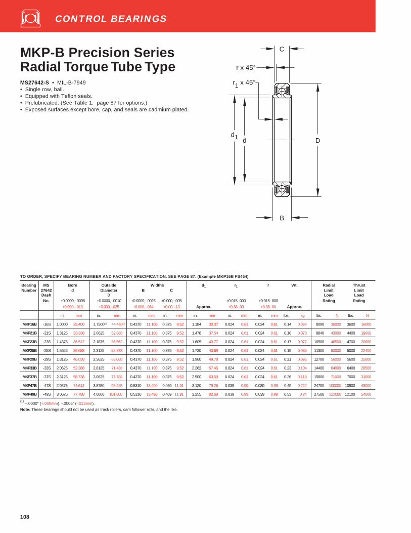
108
MKP-B Precision SeriesRadial Torque Tube TypeMS27642-S • MIL-B-7949• Single row, ball.• Equipped with Teflon seals.• Prelubricated. (See Table 1, page 87 for options.)• Exposed surfaces except bore, cap, and seals are cadmium plated.
TO ORDER, SPECIFY BEARING NUMBER AND FACTORY SPECIFICATION. SEE PAGE 87. (Example MKP16B FS464)
Bearing MS Bore Outside Widths d 1 r1 r Wt. Radial ThrustNumber 27642 d Diameter B C Limit Limit
Dash D Load LoadNo. +0.0000,-.0005 +0.0000,-.0010 +0.0000,-.0025 +0.000,-.005 +0.015-.000 +0.015-.000 Rating Rating
+0.000,-.013 +0.000,-.025 +0.000,-.064 +0.00,-.13 Approx. +0.38-.00 +0.38-.00 Approx.
in. mm in. mm in. mm in. mm in. mm in. mm in. mm lbs. kg lbs. N lbs. N
MKP16B -16S 1.0000 25.400 1.7500(1) 44.450(1) 0.4370 11.100 0.375 9.52 1.184 30.07 0.024 0.61 0.024 0.61 0.14 0.064 8090 36000 3600 16000
MKP21B -21S 1.3125 33.338 2.0625 52.388 0.4370 11.100 0.375 9.52 1.478 37.54 0.024 0.61 0.024 0.61 0.16 0.073 9840 43000 4400 19600
MKP23B -23S 1.4375 36.512 2.1875 55.562 0.4370 11.100 0.375 9.52 1.605 40.77 0.024 0.61 0.024 0.61 0.17 0.077 10500 46500 4700 20800
MKP25B -25S 1.5625 39.688 2.3125 58.738 0.4370 11.100 0.375 9.52 1.720 43.69 0.024 0.61 0.024 0.61 0.19 0.086 11300 50000 5000 22400
MKP29B -29S 1.8125 46.038 2.5625 65.088 0.4370 11.100 0.375 9.52 1.960 49.78 0.024 0.61 0.024 0.61 0.21 0.095 12700 56000 5600 25000
MKP33B -33S 2.0625 52.388 2.8125 71.438 0.4370 11.100 0.375 9.52 2.262 57.45 0.024 0.61 0.024 0.61 0.23 0.104 14400 64000 6400 28500
MKP37B -37S 2.3125 58.738 3.0625 77.788 0.4370 11.100 0.375 9.52 2.500 63.50 0.024 0.61 0.024 0.61 0.26 0.118 15800 71000 7000 31000
MKP47B -47S 2.9375 74.612 3.8750 98.425 0.5310 13.490 0.469 11.91 3.120 79.25 0.039 0.99 0.039 0.99 0.49 0.222 24700 100000 10900 48000
MKP49B -49S 3.0625 77.788 4.0000 101.600 0.5310 13.490 0.469 11.91 3.255 82.68 0.039 0.99 0.039 0.99 0.53 0.24 27500 122000 12100 54000
(1) +.0000" (+.000mm), -.0005" (-.013mm).
Note: These bearings should not be used as track rollers, cam follower rolls, and the like.
CONTROL BEARINGS
C
d D
B
r1 x 45°
d1
r x 45°

109
MKP-BS Precision SeriesSelf-AligningTorque Tube Type• Single row, ball, externally self-aligning.• Equipped with Teflon seals.• Exposed surfaces except bore, cap, and seals are cadmium plated.• Prelubricated. (See Table 1, page 87 for options.)• This series is internally identical to the MKP-B series. Self-alignment
is provided by an external self-aligning ring whose internal spherical-ground surface is accurately matched to the external spherical-ground surface of the outer ring. These bearings are designed tocompensate for initial misalignment.
TO ORDER, SPECIFY BEARING NUMBER AND FACTORY SPECIFICATION. SEE PAGE 87. (Example MKP16BS FS464)
Bearing Bore Outside Widths d 1 r1 r D1 Ø Wt. Radial ThrustNumber d Diameter B C To Limit Limit
D Sharp Misalignment Load Load+0.0000,-.0005 +0.0000,-.0010 +0.0000,-.0025 +0.000,-.005 +0.015,-.000 +0.015,-.000 Corner Either Rating Rating+0.000,-.013 +0.000,-.025 +0.000,-.064 +0.00,-.13 Approx. +0.38,-.00 +0.38,-.00 (ref.) Direction Approx.
in. mm in. mm in. mm in. mm in. mm in. mm in. mm in. mm lbs. kg lbs. N lbs. N
MKP16BS 1.0000 25.400 1.9375 49.212 0.4370 11.100 0.375 9.52 1.184 30.07 0.024 0.61 0.024 0.61 1.709 43.41 7°25' 0.18 0.082 8090 36000 1600 7100
MKP21BS 1.3125 33.338 2.2500 57.150 0.4370 11.100 0.375 9.52 1.478 37.54 0.024 0.61 0.024 0.61 2.028 51.51 6°30' 0.2 0.091 9840 43000 2000 9000
*MKP23BS 1.4375 36.612 2.3750 60.325 0.4370 11.100 0.375 9.52 1.605 40.77 0.024 0.61 0.024 0.61 2.155 54.74 6° 0.22 0.1 10500 46500 2200 9800
MKP25BS 1.5625 39.688 2.5000 63.500 0.4370 11.100 0.375 9.52 1.720 43.69 0.024 0.61 0.024 0.61 2.282 57.96 5°45' 0.25 0.113 11300 50000 2300 10200
MKP29BS 1.8125 46.038 2.7500 69.850 0.4370 11.100 0.375 9.52 1.960 49.78 0.024 0.61 0.024 0.61 2.535 64.39 5° 0.27 0.122 12700 56000 2600 11600
*MKP33BS 2.0625 52.388 3.0000 76.200 0.4370 11.100 0.375 9.52 2.262 57.45 0.024 0.61 0.024 0.61 2.787 70.79 5° 0.3 0.136 14400 64000 2900 12900
*MKP37BS 2.3125 58.738 3.2500 82.550 0.4370 11.100 0.375 9.52 2.500 63.50 0.024 0.61 0.024 0.61 3.039 77.19 4°30' 0.33 0.15 15800 71000 3200 14300
*MKP47BS 2.9375 74.612 4.1250 104.775 0.5310 13.490 0.469 11.91 3.120 79.25 0.039 0.99 0.039 0.99 3.846 97.69 4°30' 0.64 0.29 24700 100000 5000 22400
MKP48BS 3.0000 76.200 4.2500 107.950 0.5310 13.490 0.469 11.91 3.255 82.68 0.039 0.99 0.039 0.99 3.972 100.89 4° 0.69 0.313 27500 122000 5500 24500
MKP49BS 3.0625 77.788 4.2500 107.950 0.5310 13.490 0.469 11.91 3.255 82.68 0.039 0.99 0.039 0.99 3.972 100.89 4° 0.69 0.313 27500 122000 5500 24500
Note: These bearings should not be used as track rollers, cam follower rolls, and the like.
*Check for availability.
CONTROL BEARINGS
C
d D
B
r x 45°
r1 x 45°
d1D1

110
MKSP, MKSP-APrecision SeriesSelf-Aligning TypeMS27645 • MIL-B-7949• Single row, ball, self-aligning.• Equipped with bonded Teflon seals.• Exposed surfaces except bore, cap, and seals are cadmium plated.• Prelubricated. (See Table 1, page 87 for options.)
TO ORDER, SPECIFY BEARING NUMBER AND FACTORY SPECIFICATION. SEE PAGE 87. (Example MKSP3L FS464)
Bearing MS Bore Outside Widths d 1 r1 r Wt. Radial ThrustNumber (1) 27645 d Diameter B C Limit Limit
Dash D Load Load
No. +0.0000,-.0003 +0.0000,-.0004 +0.0000,-.0025 +0.000,-.005 +0.015-.000 +0.015-.000 Rating Rating
+0.000,-.008 +0.000,-.010 +0.000,-.064 +0.00,-.13 Approx. +0.38-.00 +0.38-.00 Approx.
in. mm in. mm in. mm in. mm in. mm in. mm in. mm lbs. kg lbs. N lbs. N
MKSP3L -3AR 0.1900 4.826 0.6250 15.875 0.2450 6.220 0.203 5.16 0.256 6.50 0.005 0.13 0.016 0.41 0.01 0.005 550 2450 100 450
MKSP4A -4AR 0.2500 6.350 0.7500 19.050 0.2810 7.140 0.219 5.56 0.328 8.33 0.005 0.13 0.016 0.41 0.02 0.009 900 4000 200 900
MKSP5A -5AR 0.3125 7.938 0.8125 20.638 0.2970 7.540 0.234 5.94 0.389 9.88 0.015 0.38 0.016 0.41 0.02 0.009 1000 4400 200 900
MKSP6A -6AR 0.3750 9.525 0.8750 22.225 0.3130 7.950 0.250 6.35 0.462 11.73 0.016 0.41 0.016 0.41 0.03 0.014 1120 5000 200 900
MKSP3 -3R 0.1900 4.826 0.7774 19.746 0.2970 7.540 0.270 6.86 0.297 7.54 0.005 0.13 0.022 0.56 0.03 0.014 900 4000 200 900
MKSP4 -4R 0.2500 6.350 0.9014 22.896 0.4840 12.290 0.335 8.51 0.396 10.06 0.005 0.13 0.032 0.81 0.04 0.018 1410 6300 300 1340
MKSP5 -5R 0.3125 7.938 1.2500 31.750 0.5580 14.170 0.375 9.52 0.567 14.40 0.015 0.38 0.032 0.81 0.1 0.045 2190 9800 300 1340
MKSP6 -6R 0.3750 9.525 1.4375 36.512 0.6200 15.750 0.469 11.91 0.612 15.54 0.015 0.38 0.032 0.81 0.15 0.068 2980 13200 400 1760
*MKSP8 -8R 0.5000 12.700 1.6875 42.862 0.6200 15.750 0.500 12.70 0.796 20.22 0.015 0.38 0.044 1.12 0.23 0.104 3670 16300 500 2240
*MKSP10 -10R 0.6250 15.875 1.9375 49.212 0.8130 20.650 0.625 15.88 0.922 23.42 0.015 0.38 0.044 1.12 0.37 0.168 5320 23600 600 2650
(1) These bearings are self-aligning for 10° in either direction except MKSP4A, MKSP5A and MKSP6ANote: These bearings should not be used as track rollers, cam follower rolls, and the like.
which are self-aligning for 8° in either direction.Caution: Do not allow these bearings to act as misalignment stops.
*Check for availability.
CONTROL BEARINGS
C
d D
r x 45°
r1 x 45°
d1
B

111
MDW, MDPP, MDSPPrecision SeriesMS27643/MS27647 • MIL-B-7949• Double row.• Equipped with Teflon seals.• Exposed surfaces except bore, cap, and seals are cadmium plated.• Prelubricated. (See Table 1, page 87 for options.)
TO ORDER, SPECIFY BEARING NUMBER AND FACTORY SPECIFICATION. SEE PAGE 87. (Example MDSP3 FS464)
Bearing MS Bore Outside Widths d 1 r1 r Wt. Radial ThrustNumber 27647 d Diameter B C Limit Limit
D Dash Load Load
No. +0.0000,-.0003 +0.0000,-.0004 +0.0000,-.0025 +0.000,-.005 +0.015,-.000 +0.015,-.000 Rating Rating
+0.000,-.008 +0.000,-.010 +0.000,-.064 +0.00,-.13 Approx. +0.38,-.00 +0.38,-.00 Approx.
in. mm in. mm in. mm in. mm in. mm in. mm in. mm lbs. kg lbs. N lbs. N
MDW4K2(1) -4AR 0.2500 6.350 0.6250 15.875 0.5620 14.275 0.500 12.70 0.339 8.61 0.005 0.13 0.016 0.41 0.025 0.011 1400 6200 500 2240
*MDW4K(1) -4R 0.2500 6.350 0.7500 19.050 0.8750 22.225 0.750 19.05 0.380 9.65 0.005 0.13 0.016 0.41 0.04 0.018 2770 12200 900 4000
*MDW4 — 0.2500 6.350 0.7500 19.050 0.8750 22.225 0.750 19.05 0.375 9.52 0.005 0.13 0.016 0.41 0.06 0.027 3750 16600 1240 5500
MDW5 -5R 0.3125 7.938 0.8750 22.225 0.9380 23.825 0.813 20.65 0.469 11.91 0.005 0.13 0.016 0.41 0.07 0.032 5140 22800 1600 7100
MDW6 -6R 0.3750 9.525 1.0625 26.988 1.1880 30.175 1.063 27.00 0.573 14.55 0.005 0.13 0.016 0.41 0.12 0.054 8440 37500 2600 11600
MDW8 -8R 0.5000 12.700 1.4375 36.512 1.5000 38.100 1.375 34.92 0.712 18.08 0.005 0.13 0.032 0.81 0.29 0.132 15520 69500 4700 20800
*MDPP3 — 0.1900 4.826 0.7774 19.746 0.4950 12.570 0.473 12.01 0.302 7.67 0.005 0.13 0.018 0.46 0.04 0.018 2950 13200 1700 7500
MDPP4 — 0.2500 6.350 0.9014 22.896 0.6200 15.750 0.491 12.47 0.410 10.41 0.005 0.13 0.032 0.81 0.06 0.027 5370 24000 1800 8000
MDPP5 — 0.3125 7.938 1.2500 31.750 0.7450 18.920 0.687 17.45 0.469 11.91 0.015 0.38 0.032 0.81 0.17 0.077 11000 49000 4000 17600
*MDPP6 — 0.3750 9.525 1.4375 36.512 0.8700 22.100 0.794 20.17 0.551 14.00 0.015 0.38 0.032 0.81 0.26 0.118 15760 69500 5300 23600
*MDPP8 — 0.5000 12.700 1.6875 42.862 0.9320 23.670 0.856 21.74 0.735 18.67 0.015 0.38 0.044 1.12 0.38 0.172 23600 104000 7800 34500
*MDPP10 — 0.6250 15.875 1.9375 49.212 0.9950 25.270 0.920 23.37 0.890 22.61 0.015 0.38 0.044 1.12 0.53 0.240 28400 127000 9400 41500
MS27643
MDSP3(2) -3R 0.1900 4.826 0.7774 19.746 0.5000 12.700 0.392 9.96 0.304 7.72 0.005 0.13 0.022 0.56 0.04 0.018 1420 6400 200 900
MDSP4(2) -4R 0.2500 6.350 0.9014 22.896 0.6870 17.450 0.464 11.79 0.430 10.92 0.005 0.13 0.032 0.81 0.06 0.027 1780 8000 300 1340
MDSP5(2) -5R 0.3125 7.938 1.2500 31.750 0.8120 20.620 0.656 16.66 0.515 13.08 0.015 0.38 0.032 0.81 0.16 0.073 3740 16600 600 2650
MDSP6(2) -6R 0.3750 9.525 1.4375 36.512 0.9370 23.800 0.750 19.05 0.564 14.33 0.015 0.38 0.032 0.81 0.24 0.109 5100 22800 800 3550
*MDSP8(2) -8R 0.5000 12.700 1.6875 42.862 1.0000 25.400 0.812 20.62 0.775 19.68 0.015 0.38 0.044 1.12 0.36 0.163 7120 31500 1000 4400
*MDSP10(2) -10R 0.6250 15.875 1.9375 49.212 1.1250 28.580 0.937 23.8 0.869 22.07 0.015 0.38 0.044 1.12 0.53 0.240 9000 40000 1300 5850
(1) Retainer type. Note: These bearings should not be used as track rollers, cam follower rolls, and the like.
(2) These bearings are self-aligning for 10° in either direction .
*Check for availability.
MDSP- Self Aligning Type MDPP- Radial Type MDW- Extra Wide Type
CONTROL BEARINGS
B
C
d Dd1
r1 x 45°
r x 45°
B
C
d Dd1
r1 x 45°
r x 45°
B
C
d Dd1
r1 x 45°
r x 45°

112
CONTROL BEARINGS
MB500 Precision SeriesTorque Tube Type• Extra light duty.• Single row, ball.• This series is made of bearing quality chromium-alloy, high carbon
steel and is not cadmium plated.• Open type – no seals or shields.• Prepacked with a preservative.
Bearing Bore Outside Widths d 1 r1(3) r (3) Wt. Radial Thrust
Number d Diameter B C Limit LimitD Load Load
+0.0000,-.0005 +0.0000,-.0005 +0.0000,-.0025 +0.000,-.005 +0.015,-.000 +0.015,-.000 Rating Rating
+0.000,-.013 +0.000,-.013 +0.000,-.064 +0.00,-.13 Approx. +0.38,-.00 +0.38,-.00 Approx.
in. mm in. mm in. mm in. mm in. mm in. mm in. mm lbs. kg lbs. N lbs. N
MB538 0.6250 15.875 1.0625 26.988 0.2810 7.140 0.250 6.35 0.777 19.74 0.015 0.38 0.015 0.38 0.02 0.009 3280 14600 1500 6700
MB539 0.7500 19.050 1.1875 30.162 0.2810 7.140 0.250 6.35 0.895 22.73 0.015 0.38 0.015 0.38 0.03 0.014 3750 16600 1700 7500
MB540 0.8750 22.225 1.3125 33.338 0.2810 7.140 0.250 6.35 1.016 25.81 0.015 0.38 0.015 0.38 0.04 0.018 4220 18600 1900 8500
MB541 1.0625 26.988 1.5000 38.100 0.2810 7.140 0.250 6.35 1.216 30.89 0.015 0.38 0.015 0.38 0.05 0.023 5000 22400 2200 9800
MB542 1.3125 33.338 1.7500 44.450 0.2810 7.140 0.250 6.35 1.451 36.86 0.015 0.38 0.015 0.38 0.07 0.032 5950 26500 2700 12000
MB543 1.5625 39.688 2.0000 50.800 0.2810 7.140 0.250 6.35 1.702 43.23 0.015 0.38 0.015 0.38 0.08 0.036 6880 30500 3200 14300
MB544 1.8125(1) 46.038(1) 2.2500(2) 57.150(2) 0.2810 7.140 0.250 6.35 1.970 50.04 0.015 0.38 0.015 0.38 0.09 0.041 7980 35500 3600 16000
MB545 2.0625(1) 52.388(1) 2.6250(2) 66.675(2) 0.2810 7.140 0.250 6.35 2.286 58.06 0.015 0.38 0.015 0.38 0.13 0.059 9220 41500 4000 17600
*MB546(3) 2.3125(1) 58.738(1) 2.8750(2) 73.025(2) 0.2810 7.140 0.250 6.35 2.527 64.19 0.015 0.38 0.015 0.38 0.15 0.068 10150 45500 4400 19600(1)
+.0000" (+.000mm), -.0008" (-.020mm).(3)
Maximum shaft or housing fillet radius which bearing corners will clear.(2)
+.0000" (+.000mm), -.0007" (-.018mm).
Note: These bearings should not be used as track rollers, cam follower rolls, and the like.
*Check for availability.
CONTROL BEARINGS
C
d D
B
d1
r1
r
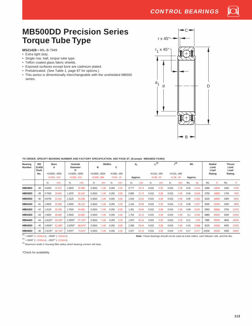
113
CONTROL BEARINGS
MB500DD Precision SeriesTorque Tube TypeMS21428 • MIL-B-7949• Extra light duty.• Single row, ball, torque tube type.• Teflon coated glass fabric shields.• Exposed surfaces except bore are cadmium plated.• Prelubricated. (See Table 1, page 87 for options.)• This series is dimentionally interchangeable with the unshielded MB500
series.
TO ORDER, SPECIFY BEARING NUMBER AND FACTORY SPECIFICATION. SEE PAGE 87. (Example MB538DD FS464)
Bearing MS Bore Outside Widths d 1 r1(3) r(3) Wt. Radial Thrust
Number 21428 d Diameter B C Limit LimitDash D Load LoadNo. +0.0000,-.0005 +0.0000,-.0005 +0.0000,-.0025 +0.000,-.005 +0.015,-.000 +0.015,-.000 Rating Rating
+0.000,-.013 +0.000,-.013 +0.000,-.064 +0.00,-.13 Approx. +0.38,-.00 +0.38,-.00 Approx.
in. mm in. mm in. mm in. mm in. mm in. mm in. mm lbs. kg lbs. N lbs. N
MB538DD -38 0.6250 15.875 1.0625 26.988 0.2810 7.140 0.250 6.35 0.777 19.74 0.015 0.38 0.015 0.38 0.03 0.014 3280 14600 1500 6700
MB539DD -39 0.7500 19.050 1.1875 30.162 0.2810 7.140 0.250 6.35 0.895 22.73 0.015 0.38 0.015 0.38 0.04 0.018 3750 16600 1700 7500
MB540DD -40 0.8750 22.225 1.3125 33.338 0.2810 7.140 0.250 6.35 1.016 25.81 0.015 0.38 0.015 0.38 0.05 0.023 4220 18600 1900 8500
MB541DD -41 1.0625 26.988 1.5000 38.100 0.2810 7.140 0.250 6.35 1.216 30.89 0.015 0.38 0.015 0.38 0.06 0.027 5000 22400 2200 9800
MB542DD -42 1.3125 33.338 1.7500 44.450 0.2810 7.140 0.250 6.35 1.451 36.86 0.015 0.38 0.015 0.38 0.09 0.041 5950 26500 2700 12000
MB543DD -43 1.5625 39.688 2.0000 50.800 0.2810 7.140 0.250 6.35 1.702 43.23 0.015 0.38 0.015 0.38 0.1 0.045 6880 30500 3200 14300
MB544DD -44 1.8125(1) 46.038(1) 2.2500(2) 57.150(2) 0.2810 7.140 0.250 6.35 1.970 50.04 0.015 0.38 0.015 0.38 0.11 0.05 7980 35500 3600 16000
MB545DD -45 2.0625(1) 52.388(1) 2.6250(2) 66.675(2) 0.2810 7.140 0.250 6.35 2.286 58.06 0.015 0.38 0.015 0.38 0.15 0.068 9220 41500 4000 17600
MB546DD -46 2.3125(1) 58.738(1) 2.875(2) 73.025(2) 0.2810 7.140 0.250 6.35 2.527 64.19 0.015 0.38 0.015 0.38 0.17 0.077 10150 45500 4400 19600(1)
+.0000" (+.000mm), -.0008" (-.020mm). Note: These bearings should not be used as track rollers, cam follower rolls, and the like.(2)
+.0000" (+.000mm), -.0007" (-.018mm).(3)
Maximum shaft or housing fillet radius which bearing corners will clear.
*Check for availability.
C
d D
B
d1
r1 x 45°
r x 45°

ROD END BEARINGS
Nomenclature
REP Series, Rod Ends, External Thread. . . . . . . . . 114
REP Series, Rod Ends, Internal Thread . . . . . . . . . 115
REP Series, Rod Ends, Hollow and Solid Shank . . 116
RA/RR Series, Rod Ends, External Thread. . . . . . . 117
RA/RR Series, Rod Ends, Hollow Shank . . . . . . . . 118
Control and Rod End BearingsRod End

Control Bearings
A stainless steelC cadmium plateM precision series
K single rowD double row
FL Fairlead typeB torque tube type
S internal self aligning typeW wide inner ring
M K S P 6 A S FS464
Bore size in 1⁄16ths of aninch. (i.e., 6⁄16" = 3⁄8" bore)
FS 464 MIL-B 7949 withMIL-G-81322 grease
FS 428 MIL-B-7949 withMIL-G-23827 grease
A, B series designator External self aligning S ring
Rod End Bearings
RE ball bearing rod end MIL-B-6039RA ball bearing rod end “NAS” seriesRR roller bearing rod end “NAS” series
RE P 4 FL 5 FS 464
P contact seal
FS 464 MIL-B-6039 withMIL-G-81322 grease
FS 428 MIL-B-6039 withMIL-G-23827 greaseP contact seal
Bore size in 1⁄16ths of aninch. (i.e.,4=4⁄16" = 1⁄4" bore)
Thread size in 1⁄16ths of aninch. (i.e., 5 refers to 5⁄16"thread size)
F female threadM male threadL left hand threadH hollow shank typeS solid shank type

114
REP SeriesExternal ThreadMS21151 • MIL-B-6039• Precision series.• Double row, ball, self-aligning.• 10° permissible misalignment in either direction.• These bearings are manufactured with an internal play of .0004"
(.010mm) max. Inner and outer raceway surface finish = 8 microinches AA max.
• Equipped with Teflon seals.• Exposed surfaces except bore, cap, and seals are cadmium plated.• Outer shank – 90,000 p.s.i. Min. Tensile Strength.• Prelubricated. (See Table 1, page 87 for options.)
TO ORDER, SPECIFY BEARING NUMBER AND FACTORY SPECIFICATION. SEE PAGE 87. (Example REPB3N FS464)
Bearing MS Bore Outside Widths d 1 L L2 L1(1) M Wt. Radial
Number 21151 d Diameter B C UNJF-3A LimitDash D Threads LoadNo. Per Rating
+0.0000,-.0003 ±.010 +0.000,-.005 ±.010 ±.010 ±.031 MIL-S-8879
+0.000,-.008 ±.25 +0.00,-.13 ±.25 Approx. ±.25 REF. ±.79 Size Approx.
in. mm in. mm in. mm in. mm in. mm in. mm in. mm in. mm lbs. kg lbs. N
REP3MR3 -2 0.1900 4.826 0.781 19.84 0.437 11.10 0.328 8.33 0.281 7.14 1.375 34.92 1.766 44.86 0.750 19.05 10-32RH 0.04 0.018 1000 4400
REP3ML3 -1 0.1900 4.826 0.781 19.84 0.437 11.10 0.328 8.33 0.281 7.14 1.375 34.92 1.766 44.86 0.750 19.05 10-32LH 0.04 0.018 1000 4400
REP3M4-6 -7 0.1900 4.826 0.781 19.84 0.437 11.10 0.328 8.33 0.281 7.14 1.375 34.92 1.953 49.61 1.000 25.40 1/4-28RH 0.05 0.023 1000 4400
REP3MS4-6(2)
-7C 0.1900 4.826 0.781 19.84 0.437 11.10 0.328 8.33 0.281 7.14 1.375 34.92 1.953 49.61 1.000 25.40 1/4-28RH 0.05 0.023 1000 4400
REP3M6-2N -4 0.1900 4.826 0.781 19.84 0.437 11.10 0.328 8.33 0.281 7.14 1.375 34.92 1.766 44.86 0.750 19.05 3/8-24RH 0.05 0.023 1000 4400
REP3MS6-2N(2)
-4C 0.1900 4.826 0.781 19.84 0.437 11.10 0.328 8.33 0.281 7.14 1.375 34.92 1.766 44.86 0.750 19.05 3/8-24RH 0.05 0.023 1000 4400
REP3ML6-2N -5 0.1900 4.826 0.781 19.84 0.437 11.10 0.328 8.33 0.281 7.14 1.375 34.92 1.766 44.86 0.750 19.05 3/8-24LH 0.05 0.023 1000 4400
REP3MLS6(2)
-5C 0.1900 4.826 0.781 19.84 0.437 11.10 0.328 8.33 0.281 7.14 1.375 34.92 1.766 44.86 0.750 19.05 3/8-24LH 0.05 0.023 1000 4400
RAP3M4-2 -6 0.1900 4.826 0.781 19.84 0.500 12.70 0.438 11.13 0.312 7.92 1.812 46.02 2.202 55.93 0.938 23.83 1/4-28RH 0.10 0.045 1000 4400
*RAP3MS4-2(2)
-6C 0.1900 4.826 0.781 19.84 0.500 12.70 0.438 11.13 0.312 7.92 1.812 46.02 2.202 55.93 0.938 23.83 1/4-28RH 0.10 0.045 1000 4400
REP3M6A -3 0.1900 4.826 0.969 24.61 0.500 12.70 0.407(4) 10.34 0.304 7.72 2.031 51.59 2.516 63.91 1.313 33.35 3/8-24RH 0.115 0.052 1200 5300
*REP3MS6A(2)
-3C 0.1900 4.826 0.969 24.61 0.500 12.70 0.407(4) 10.34 0.304 7.72 2.031 51.59 2.516 63.91 1.313 33.35 3/8-24RH 0.115 0.052 1200 5300
REP4M6 -8 0.2500 6.350 0.938 23.83 0.593 15.06 0.438 11.13 0.345 8.76 1.875 47.62 2.344 59.54 1.125 28.58 3/8-24RH 0.10 0.045 1720 7650
REP4M6-4(2)
-8C 0.2500 6.350 0.938 23.83 0.593 15.06 0.438 11.13 0.345 8.76 1.875 47.62 2.344 59.54 1.125 28.58 3/8-24RH 0.10 0.045 1720 7650
REP4ML6 -9 0.2500 6.350 0.938 23.83 0.593 15.06 0.438 11.13 0.345 8.76 1.875 47.62 2.344 59.54 1.125 28.58 3/8-24LH 0.10 0.045 1720 7650
REP4ML6-4(2)
-9C 0.2500 6.350 0.938 23.83 0.593 15.06 0.438 11.13 0.345 8.76 1.875 47.62 2.344 59.54 1.125 28.58 3/8-24LH 0.10 0.045 1720 7650
REP5M6 -10 0.3125 7.938 1.250 31.75 0.870 22.10 0.656 16.66 0.506 12.85 2.438 61.93 3.063 77.8 1.563 39.70 3/8-24RH 0.24 0.109 2920 12900
*REP5M6-2(2)
-10C 0.3125 7.938 1.250 31.75 0.870 22.10 0.656 16.66 0.506 12.85 2.438 61.93 3.063 77.8 1.563 39.70 3/8-24RH 0.24 0.109 2920 12900
REP5M7 -11 0.3125 7.938 1.250 31.75 0.870 22.10 0.656 16.66 0.506 12.85 2.438 61.93 3.063 77.8 1.563 39.70 7/16-20RH 0.24 0.109 2920 12900
*REP5MS7(2)
-11C 0.3125 7.938 1.250 31.75 0.870 22.10 0.656 16.66 0.506 12.85 2.438 61.93 3.063 77.8 1.563 39.70 7/16-20RH 0.24 0.109 2920 12900
*REP5M10 -12 0.3125 7.938 1.250 31.75 0.870 22.10 0.656 16.66 0.506 12.85 2.438 61.93 3.063 77.8 1.563 39.70 5/8-18RH 0.24 0.109 2920 12900
*REP5MS10(2)
-12C 0.3125 7.938 1.250 31.75 0.870 22.10 0.656 16.66 0.506 12.85 2.438 61.93 3.063 77.8 1.563 39.70 5/8-18RH 0.24 0.109 2920 12900
REP8M10(3)
- 0.5000 12.700 1.875 47.62 1.000 25.40 0.844 21.44 0.688 17.48 3.031 76.99 3.968 100.79 1.750 44.45 5/8-18RH 0.55 0.249 6900 30500
*RAP10M10 -13 0.6250 15.875 2.000 50.80 1.125 28.58 0.938 23.83 0.875 22.22 2.750 69.85 3.750 95.25 1.500 38.10 5/8-18RH 0.71 0.322 7090 31500
*RAP10MS10(2)
-13C 0.6250 15.875 2.000 50.80 1.125 28.58 0.938 23.83 0.875 22.22 2.750 69.85 3.750 95.25 1.500 38.10 5/8-18RH 0.71 0.322 7090 31500(1)
Length includes maximum of two incomplete threads.(3)
5° permissible misalignment in either direction.(2)
NAS 513 keyway in shank.(4)
+.000" (+.00 mm), -.015" (-.38mm).
* Check for availability.
ROD END BEARINGS
C
d
BROKENCORNERS
L1
10°
B D
L
M
d1
L2

115
REP SeriesInternal ThreadMS21153 • MIL-B-6039This series is similar in features to those shown on page 116.
TO ORDER, SPECIFY BEARING NUMBER AND FACTORY SPECIFICATION. SEE PAGE 87. (Example REPB3N FS464)
Bearing MS Bore Outside Widths d 1 L L2 L1(1) D2 D1 M Wt. Radial
Number 21153 d Diameter B C UNJF-3B LimitDash D Threads LoadNo. Per Rating
+0.0000,-.0003 ±.010 +0.000,-.005 ±.010 ±.010 ±.031 ±.010 ±.010 MIL-S-8879
+0.000,-.008 ± .25 +0.00,-.13 ± .25 Approx. ± .25 REF. ± .79 ± .25 ± .25 Size Approx.
in. mm in. mm in. mm in. mm in. mm in. mm in. mm in. mm in. mm in. mm lbs. kg lbs. N
REPB3N -1 0.1900 4.826 0.781 19.84 0.437 11.10 0.328 8.33 0.281 7.14 1.375 34.92 1.766 44.86 0.750 19.05 0.438[3] 11.13[3] 0.375 9.52 1/4-28RH 0.05 0.023 1000 4400
REP3FL4-3 -5 0.1900 4.826 0.781 19.84 0.437 11.10 0.328 8.33 0.281 7.14 1.375 34.92 1.766 44.86 0.750 19.05 0.438[3] 11.13[3] 0.375 9.52 1/4-28LH 0.05 0.023 1000 4400
REPB3N-2 -2 0.1900 4.826 0.781 19.84 0.437 11.10 0.328 8.33 0.281 7.14 1.375 34.92 1.766 44.86 0.750 19.05 0.438[4] 11.13[4] 0.483 11.13 5/16-24RH 0.06 0.027 1000 4400
REP3F4 -3 0.1900 4.826 0.781 19.84 0.500 12.70 0.328 8.33 0.281 7.14 1.375 34.92 1.766 44.86 0.750 19.05 0.438[3] 11.13[3] 0.375 9.52 1/4-28RH 0.06 0.027 1000 4400
REP3FL4 -4 0.1900 4.826 0.781 19.84 0.500 12.70 0.328 8.33 0.281 7.14 1.375 34.92 1.766 44.86 0.750 19.05 0.438[3] 11.13[3] 0.375 9.52 1/4-28LH 0.06 0.027 1000 4400
REP4F5 -6 0.2500 6.350 0.938 23.83 0.593 15.06 0.438 11.13 0.345 8.76 1.469 37.31 1.938 49.23 0.750 19.05 0.438[4] 11.13[4] 0.483 11.13 5/16-24RH 0.07 0.032 1720 7650
REP4F5-5[2] -6C 0.2500 6.350 0.938 23.83 0.593 15.06 0.438 11.13 0.345 8.76 1.469 37.31 1.938 49.23 0.750 19.05 0.438[4] 11.13[4] 0.483 11.13 5/16-24RH 0.07 0.032 1720 7650
REP4FL5[2] -7 0.2500 6.350 0.938 23.83 0.593 15.06 0.438 11.13 0.345 8.76 1.469 37.31 1.938 49.23 0.750 19.05 0.438[4] 11.13[4] 0.483 11.13 5/16-24LH 0.07 0.032 1720 7650
*REP4FL5-5[2] -7C 0.2500 6.350 0.938 23.83 0.593 15.06 0.438 11.13 0.345 8.76 1.469 37.31 1.938 49.23 0.750 19.05 0.438[4] 11.13[4] 0.483 11.13 5/16-24LH 0.07 0.032 1720 7650
REP4F7 -8 0.2500 6.350 0.938 23.83 0.593 15.06 0.438 11.13 0.345 8.76 1.875 47.62 2.344 59.54 1.125 28.58 0.625 15.88 0.625 15.88 7/16-20RH 0.08 0.036 1720 7650
*REP4FL7 -9 0.2500 6.350 0.938 23.83 0.593 15.06 0.438 11.13 0.345 8.76 1.875 47.62 2.344 59.54 1.125 28.58 0.625 15.88 0.625 15.88 7/16-20LH 0.08 0.036 1720 7650
REP5F5 -10 0.3125 7.938 1.250 31.75 0.870 22.10 0.656 16.66 0.501 12.73 1.875 47.62 2.500 63.50 1.000 25.40 0.483 11.13 0.483 11.13 5/16-24RH 0.1 0.045 2920 12900
REP5FL5 -11 0.3125 7.938 1.250 31.75 0.870 22.10 0.656 16.66 0.501 12.73 1.875 47.62 2.500 63.50 1.000 25.40 0.483 11.13 0.483 11.13 5/16-24LH 0.1 0.045 2920 12900
(1) Length includes maximum of two incomplete threads.
(3) Bead diameter.
(2) NAS 513 locking slot in shank.
(4) Hex diameter across flats.
* Check for availability.
ROD END BEARINGS
C
d
BROKENCORNERS
10°
B D
L
5/16
#50( .070 )DRILL
d1
L1
L2
D2
D1M

116
REP SeriesHollow & Solid ShankMS21152/MS21150 • MIL-B-6039• Precision series.• Double row, ball, self-aligning.• 10° permissible misalignment in either direction.• These bearings are manufactured with an internal play of .0004"
(.010mm) max. Inner and outer raceway surface finish = 8 microinches AA max.
• Equipped with Teflon seals.• Exposed surfaces except bore, cap, and seals are cadmium plated.• Outer shank - 90,000 p.s.i. Min. Tensile Strength.• Prelubricated. (See Table 1, page 87 for options.)
TO ORDER, SPECIFY BEARING NUMBER AND FACTORY SPECIFICATION. SEE PAGE 87. (Example REPB3N FS464)
Bearing MS Bore Outside Widths d 1 L L 2 L1 D1 M Wt. RadialNumber 21152 d Diameter B C Limit
Dash D Load
No. Rating
+0.0000,-.0003 ± .010 +0.000,-.005 ± .010 ± .010 ± .031 +0.000,-.002 ± .010+0.000,-.008 ± .25 +0.00,-.13 ± .25 Approx. ± .25 REF. ± .79 +0.00,-.05 ± .25 Approx.
in. mm in. mm in. mm in. mm in. mm in. mm in. mm in. mm in. mm in. mm lbs. kg lbs. N
HOLLOW SHANK
REP3H5 -1 0.1900 4.826 0.781 19.84 0.437 11.10 0.328 8.33 0.281 7.14 1.375 34.92 1.766 44.86 0.875 22.22 0.430 10.92 0.272 6.91 0.06 0.027 1000 4400
REP4H8 -3 0.2500 6.350 0.938 23.83 0.593 15.06 0.438 11.13 0.345 8.76 1.625 41.28 2.093 53.16 0.875 22.22 0.625 15.88 0.515 13.08 0.08 0.036 1720 7650
REP4H5-2 -4 0.2500 6.350 0.938 23.83 0.593 15.06 0.438 11.13 0.345 8.76 1.875 47.62 2.344 59.54 0.750 19.05 0.438 11.13 0.346 8.79 0.12 0.054 1720 7650
REP4H8-2 -5 0.2500 6.350 0.938 23.83 0.593 15.06 0.438 11.13 0.345 8.76 1.875 47.62 2.344 59.54 1.125 28.58 0.625 15.88 0.500 12.70 0.09 0.041 1720 7650
REP4H6 -2 0.2500 6.350 0.938 23.83 0.593 15.06 0.438 11.13 0.345 8.76 1.875 47.62 2.344 59.54 1.219 30.96 0.625 15.88 0.386 9.80 0.12 0.054 1720 7650
REP5H8 – 0.3125 7.938 1.250 31.75 0.870 22.10 0.656 16.66 0.506 12.85 2.438 61.93 3.063 77.80 1.562 39.67 0.625 15.88 0.500 12.70 0.15 0.068 2920 12900
REP8H10 – 0.5000 12.700 1.875 47.62 1.000 25.40 0.844 21.44 0.688 17.48 3.031 76.99 3.968 100.79 1.640 41.66 0.625 15.88 0.438 11.13 0.55 0.249 6900 30500
MS 21150
SOLID SHANK
REP3S7 -1 0.1900 4.826 0.781 19.84 0.437 11.10 0.328 8.33 0.281 7.14 1.375 34.92 1.766 44.86 – – 0.430 10.92 – – 0.07 0.032 1000 4400
REP4S10 -2 0.2500 6.350 0.938 23.83 0.593 15.06 0.438 11.13 0.345 8.76 1.875 47.62 2.344 59.54 – – 0.625 15.88 – – 0.16 0.073 1720 7650
ROD END BEARINGS
C
d1 d
BROKENCORNERS
L1
10°
B D
L
M
L2
D1

117
RA/RR SeriesExternal Thread
• Keyway in shank is designed in accordance with NAS-513 standards foruse with NAS-509 drilled jam nuts and either NAS-513 rod end lockingwashers or NAS-559 rod end key type locks.
• Permissible misalignment is 10° in either direction (total 20°).• Ultimate shank tensile strength is 125,000 to 180,000 p.s.i.• Equipped with Buna N rubber seals.
RA Ball Type RR Roller Type
• NAS-659 series(1)
.• Self-aligning.• 3-Way balanced design brings shank strength, bolt strength and
bearing capacity all in balance.• “Pressurized” shanks are designed to withstand column action under
compression with angularity as high as 9°.• Exposed surfaces except bore, cap, and seals are cadmium plated.
(5) This size not covered by NAS 659.
Lightening Holes in shank RR5M12-1⁄4" x 2 5⁄16"
RR6M14-3⁄8" x 2 9⁄16"
Left hand threaded units can be furnished as requirements justify production. Add letter “L”
to part number for left hand threads. Example: RA3ML5.* Check for availability
DIMENSIONS – TOLERANCESBearing (1) NAS Bore Outside Widths d 1 L L 2 L1
(2)b(3) T
(3)M Wt. Radial
Number 659 d Diameter B C UNJF-3A LimitDash D Thread per Load
(2)
No. +0.0000,-.0005 ± .010 +0.000,-.005 +0.010,-.005 MIL-S-8879 Rating
+0.000,-.013 ± .25 +0.00,-.13 +0.25,-.13 ± .010 ± .010 +0.005,-.000 +0.000,-.005Approx. ± .25 REF. ± .25 +0.13,-.00 +0.00,-.13 Size Approx.
in. mm in. mm in. mm in. mm in. mm in. mm in. mm in. mm in. mm in. mm lbs. kg lbs. N
*RA3M5 -3-5 0.1900 4.826 0.781 19.84 0.562 14.27 0.438 11.13 0.312 7.92 1.938 49.23 2.328 59.13 1.375 34.92 0.062 1.57 0.26 6.6 5/16-24 0.07 0.032 1000 4400
*RA3M5-2[5] – 0.1900 4.826 0.781 19.84 0.500 12.70 0.438 11.13 0.312 7.92 1.938 49.23 2.328 59.13 1.375 34.92 0.062 1.57 0.26 6.6 5/16-24 0.07 0.032 1000 4400
*RA4M7 -4-7 0.2500 6.350 0.938 23.83 0.687 17.45 0.531 13.49 0.365 9.27 2.250 57.15 2.719 69.06 1.625 41.28 0.093 2.36 0.37 9.4 7/16-20 0.13 0.059 1720 7650
*RR4M9 R4-9 0.2500 6.350 1.063 27.00 0.625 15.88 0.469 11.91 0.404 10.26 2.563 65.10 3.094 78.59 1.875 47.62 0.125 3.18 0.478 12.14 9/16-18 0.21 0.095 3025 13400
*RR5M12 R5-12 0.3125 7.938 1.438 36.53 0.812 20.62 0.656 16.66 0.515 13.08 3.125 79.38 3.844 97.64 2.219 56.36 0.125 3.18 0.663 16.84 3/4-16 0.47 0.213 7350 32500
*RR6M14 R6-14 0.3750 9.525 1.750 44.45 0.937 23.80 0.750 19.05 0.564 14.33 3.563 90.50 4.438 112.73 2.438 61.93 0.156 3.96 0.777 19.74 7/8-14 0.72 0.327 9600 42500
(1) When ordering as NAS part, add Suffix “FS237” to part number. (Example RA4M7 FS237)
(2) Threads: UNJF-3A (based on length of engagement = 1.25 thd. diam. + 5⁄8).
(3) Slots conform to NAS 513 Standards.
(4) Thrust rating is 20% of radial load rating.
ROD END BEARINGS
C
d
BROKENCORNERS
10°
B D
L
b
T
M
d1
L1
L2
C
d
BROKENCORNERS
10°
B D
L
b
T
M
L1
L2
d1

118
RA/RR Series Hollow Shank• NAS-660 series
(1).
• Self-aligning.• 3-Way balanced design brings shank strength, bolt strength and bearing
capacity all in balance.• “Pressurized” shanks are designed to withstand column action under
compression with angularity as high as 9°.
• Permissible misalignment is 10° in either direction (total 20°).• Ultimate shank tensile strength is 125,000 to 180,000 p.s.i.• Equipped with Buna N rubber seals.• Exposed surfaces except bore, cap, and seals are cadmium plated.• Prepacked with lubricant conforming to MIL-G-23827.
RA Ball Type RR Roller Type
DIMENSIONS – TOLERANCESBrg. NAS Bore Outside Widths d 1 L L 2 L1 D1 L3 M Wt. RadialNo.(1) 660 d Diameter B C Limit
Dash D LoadNo. +0.0000,-.0005 ± .010 +0.000,-.005 ± .010 ± .010 ±0.10 +0.000,-0.002 +0.010,-0.001 Rating
+0.000,-.013 ± .25 +0.00,-.13 +0 .25 Approx. ± .25 REF. ± .25 +0.25,-.05 +0.25,-.03 Approx.
in. mm in. mm in. mm in. mm in. mm in. mm in. mm in. mm in. mm in. mm in. mm lbs. kg lbs. N
*RA3H7 -3-7 0.1900 4.826 0.781 19.84 0.562 14.27 0.438 11.13 0.312 7.92 1.538 39.07 1.934 49.12 0.785 19.94 0.430 10.92 0.975 24.76 0.281 7.14 0.06 0.027 1000 4400
*RA4H9 -4-9 0.2500 6.350 0.938 23.83 0.687 17.45 0.531 13.49 0.365 9.27 1.75 44.45 2.219 56.36 0.941 23.90 0.555 14.10 1.125 28.58 0.406 10.31 0.12 0.054 1720 7650
*RA4H11 R4-11 0.2500 6.350 1.063 27.00 0.625 15.88 0.469 11.91 0.404 10.26 2.163 54.94 2.694 68.43 1.285 32.64 0.680 17.27 1.475 37.46 0.516 13.11 0.19 0.086 3025 13400
*RR5H14 R5-14 0.3125 7.938 1.438 36.53 0.812 20.62 0.656 16.66 0.515 13.08 2.906 73.81 3.625 92.08 1.785 45.34 0.870 22.10 2.094 53.19 0.703 17.86 0.4 0.181 7350 32500
*RR6H16 R6-16 0.3750 9.525 1.750 44.45 0.937 23.80 0.750 19.05 0.564 14.33 3.25 82.55 4.125 104.78 1.785 45.34 0.995 25.27 2.000 50.80 0.812 20.62 0.66 0.299 9600 42500(1)
When ordering as NAS part, add Suffix “FS237” to part number. (Example RA4H11 FS237)(2)
Thrust rating is 20% of radial load rating.
*Check for availability.
ROD END BEARINGS
C
d
BROKENCORNERS
B D
L
M
d1
L1
L2
L3
D1
C
d
BROKENCORNERS
B
M
L1
d1
D
L
D1
L2
L3

Wide Inner Ring Bearings
INDUSTRIAL SERIES
Nomenclature
Introduction . . . . . . . . . . . . . . . . . . . . . . . . . . . . . . . . . 150-151KR, KRB, KRR, KRRB, Non-Relubricatable Types . . . . . . . 153G-KRR, G-KRRB, Relubricatable Types . . . . . . . . . . . . . . . . 154GN-KRRB Heavy Series, Relubricatable Types . . . . . . . . . . 155STANDARD SERIES
RA-RR, RA-RRB Series Non-Relubricatable Types . . . . . . 156GRA-RR, GRA-RRB Series, Relubricatable Types . . . . . . . 157YA-RR, YA-RRB Series, Non-Relubricatable Types . . . . . . . 158GYA-RR, GYA-RRB Series, Relubricatable Types . . . . . . . . 159RAL-NPPB Series, Non-Relubricatable Types. . . . . . . . . . . 160SPECIAL SERIES
KL, KLB, KLL, KLLB Standard Series,
Non-Relubricatable Types . . . . . . . . . . . . . . . . . . . . . . . . . . . 161G-KLL, G-KLLB Standard Series Relubricatable Types . . . 162KLLG Series, Wireloc Non-Relubricatable Types . . . . . . . . 163GN-KLLB Heavy Series, Non-Relubricatable Types . . . . . . 164INDUSTRIAL SERIES
Tri-Ply Seal Series, Non-Relubricatable and
Relubricatable Types . . . . . . . . . . . . . . . . . . . . . . . . . . . . . . . 165GC-KRRB Series, Concentric Collar, Relubricatable Types 166GY-KRRB Setscrew Series Extra-Wide Inner,
Relubricatable Types . . . . . . . . . . . . . . . . . . . . . . . . . . . . . . . 167ER Series, Relubricatable Types . . . . . . . . . . . . . . . . . . . . . 168SM Series, A and B Types . . . . . . . . . . . . . . . . . . . . . . . . . . . 169SMN Heavy Series, A and B Types . . . . . . . . . . . . . . . . . . . . 170SM-S Series . . . . . . . . . . . . . . . . . . . . . . . . . . . . . . . . . . . . . . 171SMN-S Heavy Series . . . . . . . . . . . . . . . . . . . . . . . . . . . . . . . 172GYM-KRRB Series . . . . . . . . . . . . . . . . . . . . . . . . . . . . . . . . . 173
Page

Wide Inner Ring Ball Bearings
Prefixes:Basic Series and Additional Features
C concentric collarE metric boreG relubricatable1 standard series (200 series bearings)L light SeriesN heavy series (300 series bearings)
RA extended inner ring, one side onlySM standard series (open type bearings)
SMN heavy series (open type bearings)GY, ER, YA setscrew locking device series
M medium duty setscrew lock series
Additional FeaturesL one Mechani-seal
LL two Mechani-sealsPP two seals
R one land riding rubber sealRR two land riding rubber seals
B spherical outside diameterS external self-aligning
PP2, 3, 4, etc., —Tri-Ply seals if preceded by KTDC thin dense chrome plate
F food grade grease
Numbers:Last three numbers indicate bore size —first in inches, last two in sixteenths015 15⁄16"103 1-3⁄16"203 2-3⁄16"25 25mm (metric)40 40mm (metric)
G1 103 K RRB
Suffixes:Internal ConstructionK Conrad, non-filling slot typeW maximum capacity filling slot type
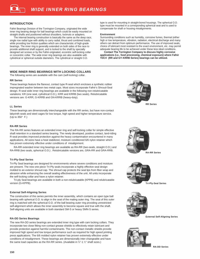
150
RR Series
RA-RR Series
Tri-Ply-Seal Series
External Self-Aligning Series
RA-DD Series
WIDE INNER RING BEARINGS WITH LOCKING COLLARSThe following series are available with the cam (self-locking) collar.
RR Series
These bearings feature the flareout, contact type R-seal which encloses a synthetic rubberimpregnated washer between two metal caps. Most sizes incorporate Fafnir’s Shroud-Sealdesign. R-seal wide inner ring bearings are available in the following non-relubricatablevariations: KR (one seal, cylindrical O.D.), KRR and KRRB (two seals). Relubricatableversions are: G-KRR, G-KRRB and GN-KRRB (heavy-duty).
LL Series
These bearings are dimensionally interchangeable with the RR series, but have non-contactlabyrinth seals and steel cages for low torque, high speed and higher temperature service.(Up to 350° F.)
RA-RR Series
The RA-RR series features an extended inner ring and self-locking collar for simple effectiveshaft retention in a standard series bearing. The newly developed, positive contact, land-ridingR-seal provides improved protection against the heavy contamination encountered in manyapplications. All sizes have a heat stabilized, moisture conditioned 6/6 nylon retainer whichhas proven extremely effective under conditions of misalignment.
RA-RR extended inner ring bearings are available as RA-RR (two-seals, straight O.D.) andRA-RRB (two seals, spherical O.D.) . Relubricatable versions are, GRA-RR and GRA-RRB.
Tri-Ply-Seal Series
Tri-Ply Seal bearings are designed for environments where severe conditions and moistureare present. The new one piece Tri-Ply seals incorporate a highly effective seal designmolded to an exterior shroud cap. The shroud cap protects the seal lips from fiber wrap andabrasion while enhancing the overall sealing effectiveness of the unit. All units incorporatethe self-locking collar and have a nylon retainer.
Tri-ply Seal bearings are available in both a non-relubricatable (KPPB) and relubricatableversion (G-KPPB).
External Self-Aligning Series
The construction of this series permits the inner assembly, which contains an open type ballbearing with spherical O.D. to align in the seat of the mating outer ring. The seat of this outerring is matched with the spherical O.D. of the ball bearing outer ring providing unrestrictedself-alignment which allows the inner assembly to become square and true with the shaft.Self-aligning units are available in both standard SM-S or heavy SMN-S series.
RA-DD Series Bearings
The new RA-DD series bearings are extended inner ring type with cam locking collars. Theyincorporate two close fitting non-contact grease shields to effectively retain lubricant andprovide protection against harmful contaminants. The non-contact metallic shields provideimproved high speed and low torque performance such as required for high speed printingpress applications. The 6/6 molded nylon retainer has proven extremely effective underconditions of misalignment. These bearings are dimensionally inter-changeable and havethe same load capacities as the RA-RR series. (Available in 5⁄8"-1 1⁄2" shaft sizes.)
type is used for mounting in straight-bored housings. The spherical O.D.type must be mounted in a corresponding spherical seat and is used tocompensate for shaft or housing misalignments.
EnvironmentSurrounding conditions such as humidity, corrosive fumes, thermal (eitherhigh or low temperature, vibration, radiation, electrical discharge and manyothers can detract from optimum performance. The use of improved seals,choice of lubricant most resistant to the exact environment, etc. may permitadequate bearing life to be achieved under these less ideal conditions.
Contact The Torrington Company to discuss highly corrosiveapplications (i.e.. food processing, chemical exposure) where FafnirTDC® (RR and GY-KRRB Series) bearings can be utilized.
WIDE INNER RING BEARINGS
INTRODUCTION
Fafnir Bearings Division of the Torrington Company, originated the wideinner ring bearing design for ball bearings which could be easily mounted onstraight shafts and positioned without shoulders, locknuts or adapters.
The internal bearing construction is basically the same as the deep race,single row radial type with ability to carry radial, thrust and combined loads,while providing low friction qualities which are characteristic of high-gradebearings. The inner ring is generally extended on both sides of the race toprovide additional shaft support, and is locked to the shaft by speciallydesigned set screws or by the Fafnir-originated, eccentric self-locking collaror concentric collar. The wide inner ring bearings are also available withcylindrical or spherical outside diameters. The cylindrical or straight O.D.

151
WIDE INNER RING BEARINGS WITH SETSCREW LOCKING DEVICEThe following series are available with the setscrew locking device with special set screws thatare resistant to loosening during operation.
GY-KRRB Series
Full width inner ring GY-KRRB bearings increase shaft support in HVAC, conveyors and otherindustrial applications. They feature superfinished raceways, grade 10 balls and antiback-outnylon patch setscrews. Flexible 6/6 nylon retainers and land riding shroud seals also ensureexcellent performance. They are factory prelubricated and relubricable setscrew mountingfeature is ideal for reversing applications.
YA-RR series
The (G)YA-RR (B) series relubricatable and non-relubricatable bearings are an extended innerring type with specially designed setscrews. Positive contact land riding R-Seals provideprotection against harmful contaminants and retain lubricant.
Setscrew Series bearings are available in both non-relubricatable version YA-RRB andrelubricatable version GYA-RRB. Both types have nylon retainers.
ER Series
This series offers industry standard mounting dimensions and standard nomenclature for alarge variety of sizes of relubricatable, extended inner ring bearings for through-boredhousings. All bearings in this series have nylon retainers and are equipped with snap ringswhich eliminate the need for machining housing shoulders. ER bearings are designed with aunique setscrew locking device, that locks bearing to shaft and is resistant to loosening duringoperation. Positive contact land riding R Seals provide protection against harmful contami-nants and retain lubricant. ER bearings are all black oxide coated for corrosion resistance.
WIDE INNER RING BEARINGS WITH CONCENTRIC COLLARSGC-KRRB Series
The GC-KRRB wide inner ring bearings are relubricatable with spherical outside diameters,nylon retainers and shroud seals. The metal shroud maintains tight seal contact against theinner ring and shields the rubber seals from damage due to dirt or fiber wrap. The concentriccollar is locked to the shaft by two setscrews, located 120° apart, which are mated withthreaded holes in the collar and drilled holes in the bearing inner ring.
GYM-KRRB MEDIUM DUTY SERIESThe new Fafnir medium duty series offers reliable performance and extended life for applica-tions which see heavier loads. This series has been designed with a combination of premiumfeatures – such as superfinished raceways and Fafnir’s nylon patch setscrew locking device,as an ideal package for demanding conditions. These superior bearing inserts will operate withreduced levels in noise, vibration and friction and are the choice antifriction component for sawand paper mill applications, as well as fan and blower assemblies, and food and grainhandling, and conveyor systems.
YA-RR Series
ER Series
GC-KRRB Series
GYM-KRRB Series
GY-KRRB Series
WIDE INNER RING BEARINGS
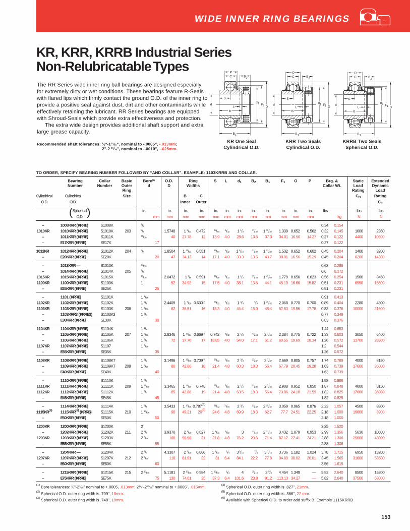
153
KR, KRR, KRRB Industrial SeriesNon-Relubricatable TypesThe RR Series wide inner ring ball bearings are designed especiallyfor extremely dirty or wet conditions. These bearings feature R-Sealswith flared lips which firmly contact the ground O.D. of the inner ring toprovide a positive seal against dust, dirt and other contaminants whileeffectively retaining the lubricant. RR Series bearings are equippedwith Shroud-Seals which provide extra effectiveness and protection.
The extra wide design provides additional shaft support and extralarge grease capacity.
Recommended shaft tolerances: 1⁄2"-1 15⁄16", nominal to -.0005", -.013mm;2"-2 15⁄16", nominal to -.0010", -.025mm .
TO ORDER, SPECIFY BEARING NUMBER FOLLOWED BY “AND COLLAR”. EXAMPLE: 1103KRRB AND COLLAR.
Bearing Collar Basic Bore (1) O.D. Ring S L d 1 B2 B1 F1 O P Brg. & Static ExtendedNumber Number Outer d D Widths Collar Wt. Load Dynamic
Ring Rating LoadCylindrical Cylindrical Size B C CO Rating
O.D. O.D. Inner Outer CE
(Spherical) in. in. in. in. in. in. in. in. in. in. in. in. lbs lbs lbsO.D. mm mm mm mm mm mm mm mm mm mm mm mm kg N N
– 1008KRR (KRRB) S1008K 1/2 0.34 0.1541010KR 1010KRR (KRRB) S1010K 203 5/8 1.5748 1 3/32 0.472 35/64
5/32 1 1/817/32 1 15/32 1.339 0.652 0.562 0.32 0.145 1000 2360
– 1011KRR (KRRB) S1011K 11/16 40 27.78 12 13.9 4.0 28.6 13.5 37.3 34.01 16.56 14.27 0.27 0.122 4400 10600– E17KRR (KRRB) SE17K 17 0.27 0.122
1012KR 1012KRR (KRRB) S1012K 204 3/4 1.8504 1 11/32 0.551 43/645/32 1 5/16
17/32 1 23/32 1.532 0.652 0.602 0.45 0.204 1400 3200– E20KRR (KRRB) SE20K 20 47 34.13 14 17.1 4.0 33.3 13.5 43.7 38.91 16.56 15.29 0.45 0.204 6200 14300
– 1013KRR — S1013K 13/16 0.63 0.286– 1014KRR (KRRB) S1014K 205 7/8 0.6 0.272
1015KR 1015KRR (KRRB) S1015K 15/16 2.0472 1 3/8 0.591 11/165/32 1 1/2
17/32 1 47/64 1.779 0.656 0.623 0.56 0.254 1560 34501100KR 1100KRR (KRRB) S1100K 1 52 34.92 15 17.5 4.0 38.1 13.5 44.1 45.19 16.66 15.82 0.51 0.231 6950 15600
– E25KRR (KRRB) SE25K 25 0.51 0.231
– 1101 (KRRB) S1101K 1 1/16 0.91 0.4131102KR 1102KRR (KRRB) S1102K 1 1/8 2.4409 1 7/16 0.630(2) 23/32 5/32 1 3/4 5/8 1 29/32 2.068 0.770 0.700 0.89 0.404 2280 48001103KR 1103KRR (KRRB) S1103K 206 1 3/16 62 36.51 16 18.3 4.0 44.4 15.9 48.4 52.53 19.56 17.78 0.83 0.376 10000 21600
– 1103KRR3 (KRRB3) S1103K3 1 1/4 0.77 0.349– E30KRR (KRRB) SE30K 30 0.83 0.376
1104KR 1104KRR (KRRB) S1104K 1 1/4 1.44 0.653– 1105KRR (KRRB) S1105K 207 1 5/16 2.8346 1 31/64 0.669(3) 0.742 5/32 2 1/8 43/64 2 1/64 2.384 0.775 0.722 1.33 0.603 3050 6400– 1106KRR (KRRB) S1106K 1 3/8 72 37.70 17 18.85 4.0 54.0 17.1 51.2 60.55 19.69 18.34 1.26 0.572 13700 28500
1107KR 1107KRR (KRRB) S1107 1 7/16 1.2 0.544– E35KRR (KRRB) SE35K 35 1.26 0.572
1108KR 1108KRR (KRRB) S1108KT 1 1/2 3.1496 1 11/16 0.709(4) 27/323/16 2 3/8
23/32 2 7/32 2.669 0.805 0.757 1.74 0.789 4000 8150– 1109KRR (KRRB) S1109KT 208 1 9/16 80 42.86 18 21.4 4.8 60.3 18.3 56.4 67.79 20.45 19.28 1.63 0.739 17600 36000– E40KRR (KRRB) SE40K 40 1.63 0.739
– 1110KRR (KRRB) S1110K 1 5/8 1.98 0.8981111KR 1111KRR (KRRB) S1111K 209 1 11/16 3.3465 1 11/16 0.748 27/32
3/16 2 1/223/32 2 7/32 2.908 0.952 0.850 1.87 0.848 4000 8150
1112KR 1112KRR (KRRB) S1112K 1 3/4 85 42.86 19 21.4 4.8 63.5 18.3 56.4 73.86 24.18 21.59 1.82 0.825 17600 36000– E45KRR (KRRB) SE45K 45 1.82 0.825
– 1114KRR (KRRB) S1114K 1 7/8 3.5433 1 15/16 0.787(5) 31/32 3 /16 2 3/4 23/32 2 15/32 3.059 0.965 0.876 2.33 1.057 4500 8800
1115KR(6) 1115KRR(6) (KRRB) S1115K 210 1 15/16 90 49.21 20(5)
24.6 4.8 69.9 18.3 62.7 77.7 24.51 22.25 2.18 1.000 19600 3900– E50KRR (KRRB) SE50K 50 2.18 1.000
1200KR 1200KRR (KRRB) S1200K 2 3.35 1.520– 1202KRR (KRRB) S1202K 211 2 1/8 3.9370 2 3/16 0.827 1 3/32 3/16 3 13/16 2 13/16 3.432 1.079 0.953 2.99 1.356 5630 10800
1203KR 1203KRR (KRRB) S1203K 2 3/16 100 55.56 21 27.8 4.8 76.2 20.6 71.4 87.17 27.41 24.21 2.88 1.306 25000 48000– E55KRR (KRRB) SE55K 55 2.88 1.306
– 1204KRR — S1204K 2 1/4 4.3307 2 7/16 0.866 1 7/321/4 3 5/16
7/8 3 1/16 3.736 1.182 1.024 3.78 1.715 6950 132001207KR 1207KRR (KRRB) S1207K 212 2 7/16 110 61.91 22 31 6.4 84.1 22.2 77.8 94.89 30.02 26.01 3.45 1.565 31000 58500
– E60KRR (KRRB) SE60K 60 3.56 1.615
– 1215KRR (KRRB) S1215K 215 2 15/16 5.1181 2 15/16 0.984 1 15/321/4 4 15/16 3 5/8 4.454 1.349 — 5.82 2.640 8500 15300
– E75KRR (KRRB) SE75K 75 130 74.61 25 37.3 6.4 101.6 23.8 91.2 113.13 34.27 — 5.82 2.640 37500 68000
(1) Bore tolerances: 1⁄2"-23⁄16" nominal to +.0005, .013mm; 21⁄4"-215⁄16" nominal to +.0006", .015mm.
(4) Spherical O.D. outer ring width is .827", 21mm.
(2) Spherical O.D. outer ring width is .709", 18mm.
(5) Spherical O.D. outer ring width is .866", 22 mm.
(3) Spherical O.D. outer ring width is .748", 19mm.
(6) Available with Spherical O.D. to order add suffix B. Example 1115KRRB
dF
D1
C
B1
B2
d
BL
S
1
OC
d
B1
B2
dF
D1
S
BL 1
O
KR One SealCylindrical O.D.
KRR Two SealsCylindical O.D.
KRRB Two SealsSpherical O.D.
B1
dF
D1
CP
d
B2
S
1
BL
WIDE INNER RING BEARINGS
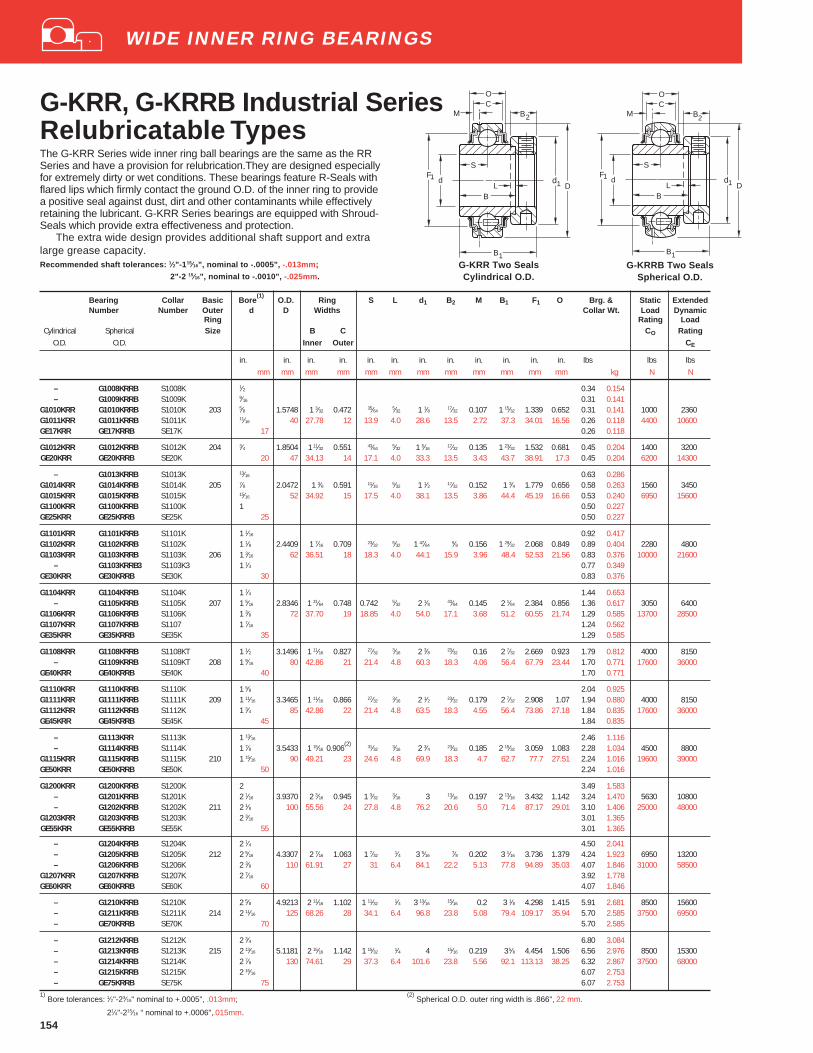
154
G-KRR, G-KRRB Industrial SeriesRelubricatable Types
C
B1
B2M
d
S
BL D
F1
1 d
O
G-KRR Two SealsCylindrical O.D.
G-KRRB Two SealsSpherical O.D.
C
d
B1
B2M
S
BL D
F1d1
O
Bearing Collar Basic Bore(1)
O.D. Ring S L d 1 B2 M B1 F1 O Brg. & Static ExtendedNumber Number Outer d D Widths Collar Wt. Load Dynamic
Ring Rating LoadCylindrical Spherical Size B C CO Rating
O.D. O.D. Inner Outer CE
in. in. in. in. in. in. in. in. in. in. in. in. lbs lbs lbsmm mm mm mm mm mm mm mm mm mm mm mm kg N N
– G1008KRRB S1008K 1⁄2 0.34 0.154– G1009KRRB S1009K 9⁄16 0.31 0.141
G1010KRR G1010KRRB S1010K 203 5⁄8 1.5748 1 3⁄32 0.472 35⁄645⁄32 1 1⁄8 17⁄32 0.107 1 15⁄32 1.339 0.652 0.31 0.141 1000 2360
G1011KRR G1011KRRB S1011K 11⁄16 40 27.78 12 13.9 4.0 28.6 13.5 2.72 37.3 34.01 16.56 0.26 0.118 4400 10600GE17KRR GE17KRRB SE17K 17 0.26 0.118
G1012KRR G1012KRRB S1012K 204 3⁄4 1.8504 1 11⁄32 0.551 43⁄64 5⁄32 1 5⁄16 17⁄32 0.135 1 23⁄32 1.532 0.681 0.45 0.204 1400 3200GE20KRR GE20KRRB SE20K 20 47 34.13 14 17.1 4.0 33.3 13.5 3.43 43.7 38.91 17.3 0.45 0.204 6200 14300
– G1013KRRB S1013K 13⁄16 0.63 0.286G1014KRR G1014KRRB S1014K 205 7⁄8 2.0472 1 3⁄8 0.591 11⁄16 5⁄32 1 1⁄2 17⁄32 0.152 1 3⁄4 1.779 0.656 0.58 0.263 1560 3450G1015KRR G1015KRRB S1015K 15⁄16 52 34.92 15 17.5 4.0 38.1 13.5 3.86 44.4 45.19 16.66 0.53 0.240 6950 15600G1100KRR G1100KRRB S1100K 1 0.50 0.227GE25KRR GE25KRRB SE25K 25 0.50 0.227
G1101KRR G1101KRRB S1101K 1 1⁄16 0.92 0.417G1102KRR G1102KRRB S1102K 1 1⁄8 2.4409 1 7⁄16 0.709 23⁄32 5⁄32 1 47⁄64 5⁄8 0.156 1 29⁄32 2.068 0.849 0.89 0.404 2280 4800G1103KRR G1103KRRB S1103K 206 1 3⁄16 62 36.51 18 18.3 4.0 44.1 15.9 3.96 48.4 52.53 21.56 0.83 0.376 10000 21600
– G1103KRRB3 S1103K3 1 1⁄4 0.77 0.349GE30KRR GE30KRRB SE30K 30 0.83 0.376
G1104KRR G1104KRRB S1104K 1 1⁄4 1.44 0.653– G1105KRRB S1105K 207 1 5⁄16 2.8346 1 31⁄64 0.748 0.742 5⁄32 2 1⁄8 43⁄64 0.145 2 1⁄64 2.384 0.856 1.36 0.617 3050 6400
G1106KRR G1106KRRB S1106K 1 3⁄8 72 37.70 19 18.85 4.0 54.0 17.1 3.68 51.2 60.55 21.74 1.29 0.585 13700 28500G1107KRR G1107KRRB S1107 1 7⁄16 1.24 0.562GE35KRR GE35KRRB SE35K 35 1.29 0.585
G1108KRR G1108KRRB S1108KT 1 1⁄2 3.1496 1 11⁄16 0.827 27⁄323⁄16 2 3⁄8 23⁄32 0.16 2 7⁄32 2.669 0.923 1.79 0.812 4000 8150
– G1109KRRB S1109KT 208 1 9⁄16 80 42.86 21 21.4 4.8 60.3 18.3 4.06 56.4 67.79 23.44 1.70 0.771 17600 36000GE40KRR GE40KRRB SE40K 40 1.70 0.771
G1110KRR G1110KRRB S1110K 1 5⁄8 2.04 0.925G1111KRR G1111KRRB S1111K 209 1 11⁄16 3.3465 1 11⁄16 0.866 27⁄32 3⁄16 2 1⁄2 23⁄32 0.179 2 7⁄32 2.908 1.07 1.94 0.880 4000 8150G1112KRR G1112KRRB S1112K 1 3⁄4 85 42.86 22 21.4 4.8 63.5 18.3 4.55 56.4 73.86 27.18 1.84 0.835 17600 36000GE45KRR GE45KRRB SE45K 45 1.84 0.835
– G1113KRR S1113K 1 13⁄16 2.46 1.116– G1114KRRB S1114K 1 7⁄8 3.5433 1 15⁄16 0.906
(2) 31⁄32 3⁄16 2 3⁄4 23⁄32 0.185 2 15⁄32 3.059 1.083 2.28 1.034 4500 8800G1115KRR G1115KRRB S1115K 210 1 15⁄16 90 49.21 23 24.6 4.8 69.9 18.3 4.7 62.7 77.7 27.51 2.24 1.016 19600 39000GE50KRR GE50KRRB SE50K 50 2.24 1.016
G1200KRR G1200KRRB S1200K 2 3.49 1.583– G1201KRRB S1201K 2 1⁄16 3.9370 2 3⁄16 0.945 1 3⁄32
3⁄16 3 13⁄16 0.197 2 13⁄16 3.432 1.142 3.24 1.470 5630 10800– G1202KRRB S1202K 211 2 1⁄8 100 55.56 24 27.8 4.8 76.2 20.6 5.0 71.4 87.17 29.01 3.10 1.406 25000 48000
G1203KRR G1203KRRB S1203K 2 3⁄16 3.01 1.365GE55KRR GE55KRRB SE55K 55 3.01 1.365
– G1204KRRB S1204K 2 1⁄4 4.50 2.041– G1205KRRB S1205K 212 2 5⁄16 4.3307 2 7⁄16 1.063 1 7⁄32
1⁄4 3 5⁄167⁄8 0.202 3 1⁄16 3.736 1.379 4.24 1.923 6950 13200
– G1206KRRB S1206K 2 3⁄8 110 61.91 27 31 6.4 84.1 22.2 5.13 77.8 94.89 35.03 4.07 1.846 31000 58500G1207KRR G1207KRRB S1207K 2 7⁄16 3.92 1.778GE60KRR GE60KRRB SE60K 60 4.07 1.846
– G1210KRRB S1210K 2 5⁄8 4.9213 2 11⁄16 1.102 1 11⁄32 1⁄4 3 13⁄16 15⁄16 0.2 3 1⁄8 4.298 1.415 5.91 2.681 8500 15600– G1211KRRB S1211K 214 2 11⁄16 125 68.26 28 34.1 6.4 96.8 23.8 5.08 79.4 109.17 35.94 5.70 2.585 37500 69500– GE70KRRB SE70K 70 5.70 2.585
– G1212KRRB S1212K 2 3⁄4 6.80 3.084– G1213KRRB S1213K 215 2 13⁄16 5.1181 2 15⁄16 1.142 1 15⁄32 1⁄4 4 15⁄16 0.219 3 5⁄8 4.454 1.506 6.56 2.976 8500 15300– G1214KRRB S1214K 2 7⁄8 130 74.61 29 37.3 6.4 101.6 23.8 5.56 92.1 113.13 38.25 6.32 2.867 37500 68000– G1215KRRB S1215K 2 15⁄16 6.07 2.753– GE75KRRB SE75K 75 6.07 2.753
1) Bore tolerances: 1⁄2"-23⁄16" nominal to +.0005", .013mm;
(2) Spherical O.D. outer ring width is .866", 22 mm.
21⁄4"-215⁄16 “ nominal to +.0006",.015mm.
WIDE INNER RING BEARINGS
The G-KRR Series wide inner ring ball bearings are the same as the RRSeries and have a provision for relubrication.They are designed especiallyfor extremely dirty or wet conditions. These bearings feature R-Seals withflared lips which firmly contact the ground O.D. of the inner ring to providea positive seal against dust, dirt and other contaminants while effectivelyretaining the lubricant. G-KRR Series bearings are equipped with Shroud-Seals which provide extra effectiveness and protection.
The extra wide design provides additional shaft support and extralarge grease capacity.Recommended shaft tolerances: 1⁄2"-1 15⁄16", nominal to -.0005", -.013mm;
2"-2 15⁄16", nominal to -.0010", -.025mm.

155
GN-KRRB Heavy SeriesRelubricatable TypeThe heavy series R-Seal wide inner ring bearings are similar to thestandard series described on page 151 but are capable of withstandingcontinuous, heavy or shock loads. The GN-KRRB series has heaviersection 300 series bearings, as well as a considerably thicker sealingmember in the contact-type diaphram seal. This design assurescomplete retention of the lubricant and positive exclusion of allcontaminents. These bearings are especially effective at slow-to-moderate speeds under the severest of conditions of dirt and corrosion.
Recommended shaft tolerances: 1 3⁄16"-1 15⁄16", nominal to -.0005", -.013mm;
2"-3 15⁄16", nominal to -.0010", -.025mm.
TO ORDER, SPECIFY BEARING NUMBER FOLLOWED BY “AND COLLAR”. Example: GN303KRRB and Collar.
Bearing Collar Basic Bore(1)
O.D. Ring S G L d 1 B2 M B1 F1 O Brg. & Static ExtendedNumber Number Outer d D Widths Collar Wt. Load Dynamic
Ring Rating LoadSize B C CO Rating
Inner Outer CE
in. in. in. in. in. in. in. in. in. in. in. in. in. lbs lbs lbsmm mm mm mm mm mm mm mm mm mm mm mm kg N N
GN103KRRB SN103K 306 1 3⁄16 2.8346 1 7⁄16 0.787 11⁄16 3⁄4 5⁄32 1 15⁄16 11⁄16 0.142 1 31⁄32 2.369 0.925 1.22 0.553 3550 750072 36.51 20 17.5 19.1 4 49.2 17.5 3.61 50 60.17 23.5 15600 33500
GN104KRRB SN104K 1 1⁄4 1.68 0.762GN105KRRB SN105K 307 1 5⁄16 3.1496 1 1⁄2 0.866 23⁄32 25⁄32 5⁄32 2 3⁄16 11⁄16 0.156 2 1⁄32 2.638 1.063 1.64 0.744 4500 9150GN106KRRB SN106K 1 3⁄8 80 38.10 22 18.3 19.8 4 55.6 17.5 3.96 51.6 67.01 27 1.6 0.726 20000 40500GN107KRRB SN107K 1 7⁄16 1.56 0.708
GN108KRRB(2)
SN108K 308 1 1⁄2 3.5433 1 5⁄8 0.984 25⁄32 27⁄32 3⁄16 2 1⁄2 13⁄16 0.182 2 1⁄4 2.955 1.05 2.54 1.152 5500 1100090 41.28 25 19.8 21.4 4.8 63.5 20.6 4.62 57.2 75.06 26.67 24500 49000
GN110KRRB SN110K 309 1 5⁄8 3.9370 1 11⁄16 1.063 25⁄32 29⁄32 3⁄16 2 3⁄4 13⁄16 0.197 2 5⁄16 3.251 1.123 3.65 1.656 6700 13200GN111KRRB SN111K 1 11⁄16 100 42.86 27 19.8 23 4.8 69.9 20.6 5 58.7 82.58 28.52 3.21 1.456 30000 58500GN112KRRB SN112K 1 3⁄4 2.95 1.388
GN114KRRB SN114K 310 1 7⁄8 4.3307 1 15⁄16 1.142 31⁄32 31⁄32 3⁄16 2 63⁄64 7⁄8 0.211 2 5⁄8 3.654 1.215 4.35 1.973 8000 15300GN115KRRB SN115K 1 15⁄16 110 49.21 29 24.6 24.6 4.8 75.8 22.2 5.36 66.7 82.87 30.86 4.2 1.905 35500 68000
GN200KRRB SN200K 311 2 4.7244 2 3⁄16 1.22 1 3⁄32 1 3⁄32 3⁄16 3 1⁄4 7⁄8 0.216 2 7⁄8 4.007 1.475 4.7 2.132 9300 18000GN203KRRB SN203K 2 3⁄16 120 55.56 31 27.8 27.8 4.8 82.6 22.2 5.49 73 101.78 37.47 5.22 2.368 41500 80000
GN207KRRB SN207K 312 2 7⁄16 5.1181 2 7⁄16 1.299 1 7⁄32 1 7⁄32 1⁄4 3 1⁄2 15⁄16 0.23 3 1⁄8 4.312 1.535 6.26 2.839 10800 20400130 61.91 33 31 31 6.4 88.9 23.8 5.84 79.4 108.52 38.99 48000 90000
GN211KRRB SO211K 314 2 11⁄16 5.9055 2 11⁄16 1.457 1 11⁄32 1 11⁄32 1⁄4 4 1 1⁄16 0.265 3 1⁄2 4.973 1.77 9.94 4.509 14300 26000150 68.26 37 34.1 34.1 6.4 101.6 27 6.73 88.9 126.31 44.96 63000 116000
GN215KRRB SN215K 315 2 15⁄16 6.2992 2 15⁄16 1.535 1 15⁄32 1 15⁄32 1⁄4 4 7⁄16 1 1⁄4 0.255 3 15⁄16 5.273 2.013 12.42 5.634 16000 28500160 74.61 39 37.3 37.3 6.4 112.7 31.8 6.48 100 133.02 51.13 71000 125000
GN303KRRB SN303K 316 3 3⁄16 6.6929 3 3⁄16 1.614 1 19⁄32 1 19⁄32 1⁄4 4 11⁄16 1 1⁄4 0.286 4 3⁄16 5.623 2.010 15.71 7.126 18000 30500170 80.96 41 40.5 40.5 6.4 119.1 31.8 7.26 106.4 142.82 51.05 80000 137000
GN307KRRB SN307K 318 3 7⁄16 7.4803 3 7⁄16 1.772 1 21⁄32 1 21⁄32 5⁄16 5 1⁄4 1 7⁄16 0.322 4 9⁄16 6.353 2.072 20.26 9.19 22400 33500190 87.31 45 42.1 42.1 7.9 133.4 36.5 8.18 115.9 161.37 52.63 98000 156000
GN315KRRB SN315K 320 3 15⁄16 8.4646 3 15⁄16 1.929 1 31⁄32 1 31⁄32 5⁄16 5 3⁄4 1 7⁄16 0.308 5 1⁄16 7.199 2.337 26.97 12.233 22900 43000215 100.01 49 50 50 7.9 146.1 36.5 7.82 129.6 182.85 59.36 132000 193000
(1) Bore tolerances: 1 3⁄16"-2 3⁄16" nominal to +.0005", .013mm; 2 1⁄4"-3 3⁄16" nominal to +.0006", .015mm.
(2) Also available with cylindrical O.D. Delete suffix “B’ Example: GN108KRR.
C
d
B1
B2M
S
BL
FD1
G
d1
O
WIDE INNER RING BEARINGS

156
RA-RR, RA-RRB Standard SeriesNon-Relubricatable Types
TO ORDER, SPECIFY BEARING NUMBER FOLLOWED BY “AND COLLAR”. EXAMPLE: RA100RRB AND COLLAR.
Bearing Collar Basic Bore (1) O.D. Ring S G L d 1 B2 B1 Brg. & Static ExtendedNumber Number Outer d D Widths Collar Wt. Load Dynamic
Cylindrical Spherical Size B C CO Rating
O.D. O.D. Inner Outer CE
in. in. in. in. in. in. in. in. in. in. lbs lbs lbsmm mm mm mm mm mm mm mm mm mm kg N N
RA008RR RA008RRB S1008K 1⁄2 0.34 0.154RA009RR RA009RRB S1009K 9⁄16 1.5748 0.750 0.512(2) 0.256 0.494 5⁄32 1 1⁄8 17⁄32 1 1⁄8 0.32 0.145 1000 2360RA010RR RA010RRB S1010K 203 5⁄8 40 19.05 13 6.5 12.55 4.0 28.6 13.5 28.6 0.28 0.127 4400 10600RAE17RR RAE17RRB SE17K 17 0.28 0.127
RA012RR RA012RRB S1012K 204 3⁄4 1.8504 0.844 0.591(3) 0.295 0.548 5⁄32 1 5⁄1617⁄32 1 7⁄32 0.29 0.132 1400 3200
RAE20RR RAE20RRB SE20K 20 47 21.44 15 7.49 13.92 4.0 33.3 13.5 31 0.29 0.132 6200 14300
RA013RR RA013RRB S1013K 13⁄16 0.51 0.231RA014RR RA014RRB S1014K 205 7⁄8 2.0472 0.844 0.591 0.295 0.548 5⁄32 1 1⁄2 17⁄32 1 7⁄32 0.47 0.213 1560 3450RA015RR RA015RRB S1015K 15⁄16 52 21.44 15 7.49 13.92 4.0 38.1 13.5 31 0.44 0.2 6950 15600RA100RR RA100RRB S1100K 1 0.41 0.186RAE25RR RAE25RRB SE25K 25 0.41 0.186
RA101RR RA101RRB S1101K 1 1⁄16 0.77 0.349RA102RR RA102RRB S1102K 1 1⁄8 2.4409 0.938 0.709 0.354 0.583 5⁄32 1 47⁄64 5⁄8 1 13⁄32 0.72 0.327 2280 4800RA103RR RA103RRB S1103K 206 1 3⁄16 62 23.82 18 8.99 14.81 4.0 44.1 15.9 35.7 0.7 0.318 10000 21600RA103RR2 RA103RRB2 S1103K3 1 1⁄4 0.65 0.295RAE30RR RAE30RRB SE30K 30 0.7 0.318
RA104RR RA104RRB S1104K 1 1⁄4 1.24 0.562RA105RR RA105RRB S1105K 207 1 5⁄16 2.8346 1.000 0.748 0.374 0.626 5⁄32 2 1⁄8 43⁄64 1 17⁄32 1.19 0.54 3050 6400RA106RR RA106RRB S1106K 1 3⁄8 72 25.4 19 9.5 15.9 4.0 54.40 17.1 38.9 1.13 0.513 13700 28500RA107RR RA107RRB S1107K 1 7⁄16 1.05 0.476RAE35RR RAE35RRB SE35K 35 1.13 0.513
RA108RR RA108RRB S1108K 1 1⁄2 3.1496 1.188 0.866(4) 0.433 0.755 3⁄16 2 3⁄8 23⁄32 1 23⁄32 1.53 0.694 4000 8150RA109RR RA109RRB S1109K 208 1 9⁄16 80 30.18 22 11 19.18 4.8 60.3 18.3 43.7 1.43 0.649 17600 36000RAE40RR RAE40RRB SE40K 40 1.43 0.649
RA110RR RA110RRB S1110K 1 5⁄8 1.72 0.78RA111RR RA111RRB S1111K 209 1 11⁄16 3.3465 1.188 0.866 0.433 0.755 3⁄16 2 1⁄2 23⁄32 1 23⁄32 1.62 0.735 4000 8150RA112RR RA112RRB S1112K 1 3⁄4 85 30.18 22 11 19.18 4.8 63.5 18.3 43.7 1.5 0.68 17600 36000RAE45RR RAE45RRB SE45K 45 1.5 0.68
RA113RR RA113RRB S1113K 1 13⁄16 1.94 0.88RA114RR RA114RRB S1114K 1 7⁄8 3.5433 1.188 0.866 0.433 0.755 3⁄16 2 3⁄4 23⁄32 1 23⁄32 1.83 0.83 4500 8800RA115RR RA115RRB S1115K 210 1 15⁄16 90 30.18 22 11 19.18 4.8 69.9 18.3 43.7 1.70 0.771 19600 39000RA115RR2 RA115RRB2 S1115K2 2 1.58 0.717RAE50RR RAE50RRB SE50K 50 1.79 0.771
RA200RR RA200RRB S1200K 2 2.12 0.962RA201RR RA201RRB S1201K 2 1⁄16 3.9370 1.281 0.945 0.472 0.809 3⁄16 3 13⁄16 1 29⁄32 1.98 0.898RA202RR RA202RRB S1202K 211 2 1⁄8 100 32.54 24 11.99 20.55 4.8 76.2 20.6 48.4 1.89 0.857 5630 10800RA203RR RA203RRB S1203K 2 3⁄16 1.78 0.807 25000 48000RAE55RR RAE55RRB SE55K 55 1.78 0.807
(1) Bore tolerance is nominal to +.0005", .013mm
(3) Spherical O.D. outer ring width is .551", 14mm
(2) Spherical O.D. outer ring width is .472", 12mm
(4) Spherical O.D. outer ring width is .827", 21mm
B
L
SG
B
d1
B2
C
Dd
1 B
L
SG
B
d1
B2
C
Dd
1
RA-RR Two SealsCylindrical O.D.
RA-RRB Two SealsSpherical O.D.
WIDE INNER RING BEARINGS
The RA-RR Series bearings are extended inner ring type with self-locking collar. A positive contact, land riding R-seal providesimproved protection against harmful contaminants and effectivelyretains the lubricant under severe operating conditions. A 6/6 moldednylon retainer has proven extremely effective under conditions ofmisalignment. RA-RR Series bearings are factory prelubricated.
The RA-RR Series has cylindrical outside diameters.The RA-RRB Series has spherical outside diameters for use in
housings with corresponding spherical inside surfaces to provideunrestricted initial alignment.
Recommended shaft tolerances: 1⁄2"-1 15⁄16", nominal to -.0005", -.013mm;
2"-2 3/16", nominal to -.0010", -.025mm.
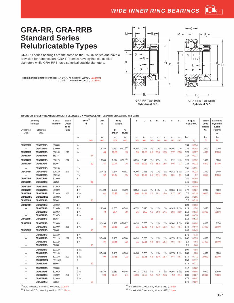
157
TO ORDER, SPECIFY BEARING NUMBER FOLLOWED BY “AND COLLAR.” Example: GRA100RRB and Collar
Bearing Collar Basic Bore(1)
O.D. Ring S G L d 1 B2 M B1 Brg. & Static ExtendedNumber Number Outer d D Widths Collar Wt. Load Dynamic
Ring Rating LoadCylindrical Spherical Size B C Co Rating O.D. O.D. Inner Outer CE
in. in. in. in. in. in. in. in. in. in. in. lbs lbs lbsmm mm mm mm mm mm mm mm mm mm mm kg N N
GRA008RR GRA008RRB S1008K 1⁄2 0.34 0.154— GRA009RRB S1009K 9⁄16 1.5748 0.750 0.512
(2)0.256 0.494 5⁄32 1 1⁄8 17⁄32 0.107 1 1⁄8 0.32 0.145 1000 2360
GRA010RR GRA010RRB S1010K 203 5⁄8 40 19.05 13 6.5 12.55 4.0 28.6 13.5 2.72 28.6 0.28 0.127 4400 10600GRAE17RR GRAE17RRB SE17K 17 0.28 0.127
GRA012RR GRA012RRB S1012K 204 3⁄4 1.8504 0.844 0.591(3) 0.295 0.548 5⁄32 1 5⁄1617⁄32 0.12 1 7⁄32 0.29 0.132 1400 3200
GRAE20RR GRAE20RRB SE20K 20 47 21.44 15 7.49 13.92 4.0 33.3 13.5 3.05 31 0.29 0.132 6200 14300
— GRA013RRB S1013K 13⁄16 0.51 0.231GRA014RR GRA014RRB S1014K 205 7⁄8 2.0472 0.844 0.591 0.295 0.548 5⁄32 1 1⁄2 17⁄32 0.142 1 17⁄32 0.47 0.213 1560 3450
— GRA015RRB S1015K 15⁄16 52 21.44 15 7.49 13.92 4.0 38.1 13.5 3.61 31 0.44 0.2 6950 15600GRA100RR GRA100RRB S1100K 1 0.41 0.186GRAE25RR GRAE25RRB SE25K 25 0.41 0.186
GRA101RR GRA101RRB S1101K 1 1⁄16 0.77 0.349GRA102RR GRA102RRB S1102K 1 1⁄8 2.4409 0.938 0.709 0.354 0.583 5⁄32 1 47⁄64
5⁄8 0.164 1 13⁄32 0.72 0.327 2280 4800GRA103RR GRA103RRB S1103K 206 1 3⁄16 62 23.83 18 8.99 14.81 4.0 44.1 15.9 4.17 35.7 0.7 0.318 10000 21600GRA103RR2 GRA103RRB2 S1103K3 1 1⁄4 0.65 0.295GRAE30RR GRAE30RRB SE30K 30 0.7 0.318
GRA104RR GRA104RRB S1104K 1 1⁄4 1.24 0.562— GRA105RRB S1105K 207 1 5⁄16 2.8346 1.000 0.748 0.374 0.626 5⁄32 2 1⁄8 43⁄64 0.145 1 17⁄32 1.19 0.54 3050 6400— GRA106RRB S1106K 1 3⁄8 72 25.4 19 9.5 15.9 4.0 54.0 17.1 3.68 38.9 1.13 0.513 13700 28500— GRA107RRB S1107K 1 7⁄16 1.05 0.476
GRAE35RR GRAE35RRB SE35K 35 1.13 0.513
GRA108RR GRA108RRB S1108K 1 1⁄2 3.1496 1.188 0.866(4) 0.433 0.755 3⁄16 2 3⁄8 23⁄32 0.164 1 23⁄32 1.53 0.694 4000 8150— GRA109RRB S1109K 208 1 9⁄16 80 30.18 22 11 19.18 4.8 60.3 18.3 4.17 43.7 1.43 0.649 17600 36000
GRAE40RR GRAE40RRB SE40K 40 1.43 0.649
— GRA110RRB S1110K 1 5⁄8 1.72 0.78— GRA111RRB S1111K 209 1 11⁄16 3.3465 1.188 0.866 0.433 0.755 3⁄16 2 1⁄2 23⁄32 0.179 1 23⁄32 1.62 0.735 4000 8150— GRA112RRB S1112K 1 3⁄4 85 30.18 22 11 19.18 4.8 63.5 18.3 4.55 43.7 1.5 0.68 17600 36000— GRAE45RRB SE45K 45 1.5 0.68
— GRA113RRB S1113K 1 13⁄16 1.94 0.88— GRA114RRB S1114K 1 7⁄8 3.5433 1.188 0.866 0.433 0.755 3⁄16 2 3⁄4 23⁄32 0.175 1 23⁄32 1.83 0.83 4500 8800— GRA115RRB S1115K 210 1 15⁄16 90 30.18 22 11 19.18 4.8 69.9 18.3 4.44 43.7 1.70 0.771 19600 39000— GRA115RRB2 S1115K2 2 1.58 0.717— GRAE50RRB SE50K 50 1.79 0.771
— GRA200RRB S1200K 2 2.12 0.962— GRA201RRB S1201K 2 1⁄16 3.9370 1.281 0.945 0.472 0.809 3⁄16 3 13⁄16 0.193 1 29⁄32 1.98 0.898 5600 10800— GRA202RRB S1202K 211 2 1⁄8 100 32.54 24 11.99 20.55 4.8 76.2 20.6 4.9 48.4 1.89 0.857 25000 48000— GRA203RRB S1203K 2 3⁄16 1.78 0.807— GRAE55RRB SE55K 55 1.78 0.807
(1) Bore tolerance is nominal to +.0005, .013mm
(3) Spherical O.D. outer ring width is .551", 14mm
(2) Spherical O.D. outer ring width is .472", 12mm
(4) Spherical O.D. outer ring width is .827", 21mm
GRA-RR, GRA-RRBStandard SeriesRelubricatable TypesGRA-RR series bearings are the same as the RA-RR series and have aprovision for relubrication. GRA-RR series have cylindrical outsidediameters while GRA-RRB have spherical outside diameters.
Recommended shaft tolerances: 1⁄2"-1 15⁄16", nominal to -.0005", -.013mm;2"-2 15/16", nominal to -.0010", -.025mm.
L
SG
B
d1
C
2
B
Dd
1
BM
L
SG
B
d1
C
2B
B
M
Dd
1GRA-RRB Two Seals
Spherical O.D.
WIDE INNER RING BEARINGS
GRA-RR Two SealsCylindrical O.D.

158
YA-RR, YA-RRBStandard SeriesNon-Relubricatable Types
Bearing Basic Bore(1)
O.D. Ring S F J Set Brg. Static ExtendedNumber Outer d D Widths Screw Wt. Load Dynamic
Ring Size Rating LoadCylindrical Spherical Size B C CO Rating
O.D. O.D. Inner Outer CE
in. in. in. in. in. in. in. in. lbs lbs lbsmm mm mm mm mm mm mm mm kg N N
YA008RR YA008RRB 1⁄2 1.5748 0.938 0.512(2) 0.313 31⁄32 0.187 10-32 0.19 1000 2360YA010RR YA010RRB 203 5⁄8 40 23.8 13 7.95 24.6 4.75 M5X.8 0.09 4400 10600YAE17RR YAE17RRB 17
YA012RR YA012RRB 204 3⁄4 1.8504 1.063 0.591(3) 0.349 1 9⁄64 0.237 1⁄4-28 0.3 1400 3200YAE20RR YAE20RRB 20 47 27 15 8.86 29 6.02 M6X1 0.14 6200 14300
YA014RR YA014RRB 205 7⁄8YA015RR YA015RRB 15⁄16 2.0472 1.109 0.591 0.348 1 21⁄64 0.250 1⁄4-28 0.38 1560 3450YA100RR YA100RRB 1 52 28.2 15 8.84 33.7 6.35 M6X1 0.17 6950 15600YAE25RR YAE25RRB 25
YA102RR YA102RRB 1 1⁄8YA103RR YA103RRB 206 1 3⁄16 2.4409 1.281 0.709 0.38 1 37⁄64 0.310 5⁄16-24(4) 0.58 2280 4800YA103RR2 YA103RRB2 1 1⁄4 62 32.5 18 9.65 40.1 7.87 M8X1.25 0.26 10000 21600YAE30RR YAE30RRB 30
YA104RR YA104RRB 1 1⁄4YA106RR YA106RRB 207 1 3⁄8 2.8346 1.444 0.748 0.427 1 27⁄32 0.310 5⁄16-24 0.93 3050 6400YA107RR YA107RRB 1 7⁄16 72 36.5 19 10.85 46.8 7.87 M8X1.25 0.42 13700 28500YAE35RR YAE35RRB 35
YA108RR YA108RRB 208 1 1⁄2 3.1496 1.538 0.8661(5) 0.458 2 1⁄16 0.310 5⁄16-24 1.24 4000 8150YAE40RR YAE40RRB 40 80 39.3 22 11.63 52.4 7.87 M8X1.25 0.56 17600 36000
YA110RR YA110RRB 1 5⁄8YA111RR YA111RRB 209 1 11⁄16 3.3465 1.655 0.8861 0.53 2 9⁄32 0.310 5⁄16-24 1.18 4000 8150YA112RR YA112RRB 1 3⁄4 85 42 22 13.46 57.9 7.87 M8X1.25 0.54 17600 36000YAE45RR YAE45RRB 45
YA115RR YA115RRB 210 1 15⁄16 3.5433 1.746 0.8661 0.53 2 15⁄32 0.355 3⁄8-24 1.25 4500 8800YA115RR2 YA115RRB2 2 90 44.3 22 13.46 62.7 9.02 M10X1.5 0.57 19600 39000YAE50RR YAE50RRB 50
YA200RR YA200RRB 211 2 3.9370 1.833 0.9449 0.575 2 3⁄4 0.355 3⁄8-24 1.27 5600 10800YA203RR YA203RRB 2 3⁄16 100 46.6 24 14.6 69.8 9.02 M10X1.5 0.58 25000 48000YAE55RR YAE55RRB 55
(1) Bore tolerance is nominal to +.0005, .013mm
(4) YA103RR2 and YA103RRB2 use 1⁄4-28 setscrew.
(2) Spherical O.D. outer ring width is .4724", 12mm
(5) Spherical O.D. outer ring width is .8268", 21mm
(3) Spherical O.D. outer ring width is .5512", 14mm
YA-RR Cylindrical O.D. YA-RRB Spherical O.D.
WIDE INNER RING BEARINGS
S
F
J
B
C
dD
S
F
J
B
C
dD
The YA-RR and YA-RRB Series bearings are extended inner ringtype with specially designed setscrews with unique thread form thatlocks bearing to shaft and are resistant to loosening during operation.A positive contact, land riding R-seal provides improved protectionagainst harmful contaminants and effectively retains the lubricantunder severe operating conditions. A 6/6 molded nylon retainer hasproven extremely effective under conditions of misalignment.
The YA-RR Series has cylindrical outside diameters. The YA-RRBSeries has spherical outside diameters for use in housings withcorresponding spherical inside surfaces to provide unrestricted initialself-alignment.
Recommended shaft tolerances: 1⁄2"-1 15⁄16", nominal to -.0005", -.013mm;
2"-2 15⁄16", nominal to -.0010", -.025mm.
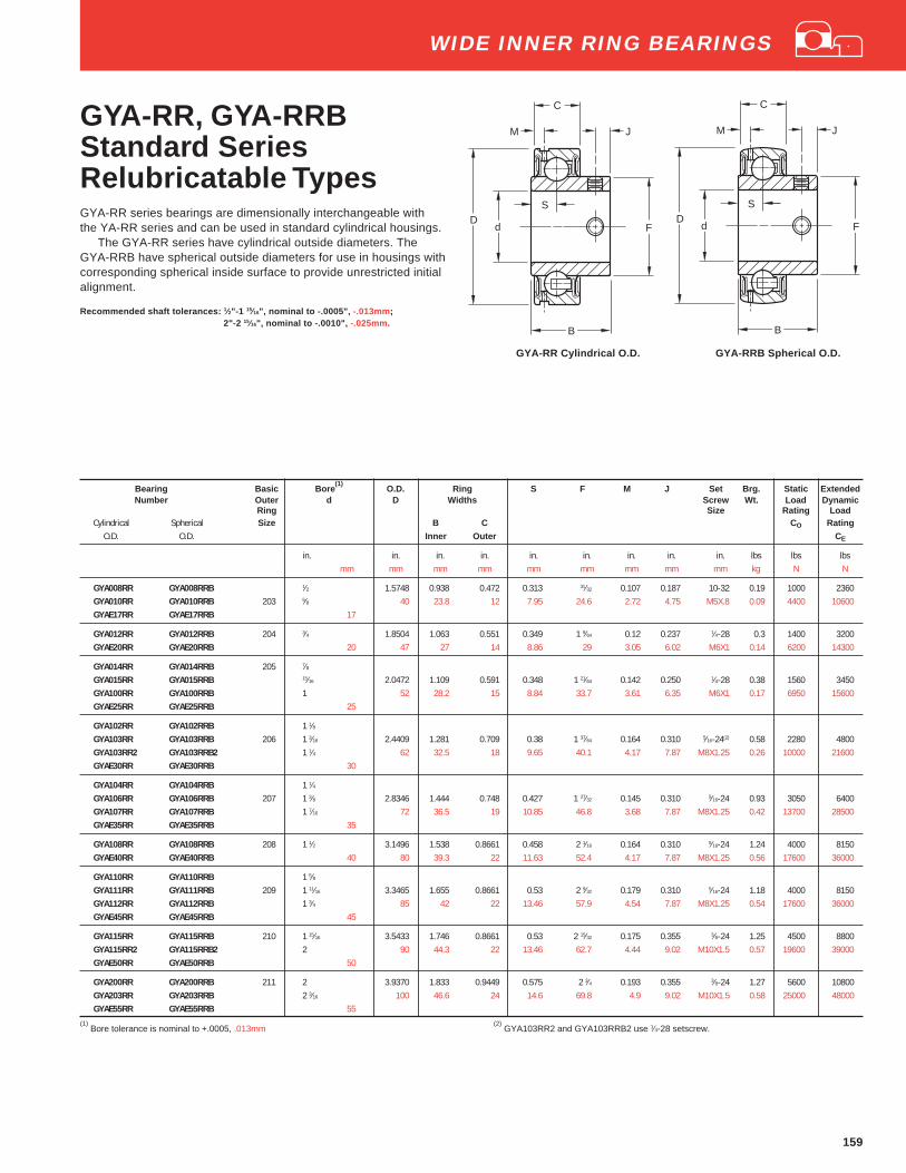
159
GYA-RR, GYA-RRBStandard SeriesRelubricatable TypesGYA-RR series bearings are dimensionally interchangeable withthe YA-RR series and can be used in standard cylindrical housings.
The GYA-RR series have cylindrical outside diameters. TheGYA-RRB have spherical outside diameters for use in housings withcorresponding spherical inside surface to provide unrestricted initialalignment.
Recommended shaft tolerances: 1⁄2"-1 15⁄16", nominal to -.0005", -.013mm;2"-2 15⁄16", nominal to -.0010", -.025mm.
Bearing Basic Bore(1)
O.D. Ring S F M J Set Brg. Static ExtendedNumber Outer d D Widths Screw Wt. Load Dynamic
Ring Size Rating LoadCylindrical Spherical Size B C CO Rating
O.D. O.D. Inner Outer CE
in. in. in. in. in. in. in. in. in. lbs lbs lbsmm mm mm mm mm mm mm mm mm kg N N
GYA008RR GYA008RRB 1⁄2 1.5748 0.938 0.472 0.313 31⁄32 0.107 0.187 10-32 0.19 1000 2360GYA010RR GYA010RRB 203 5⁄8 40 23.8 12 7.95 24.6 2.72 4.75 M5X.8 0.09 4400 10600GYAE17RR GYAE17RRB 17
GYA012RR GYA012RRB 204 3⁄4 1.8504 1.063 0.551 0.349 1 9⁄64 0.12 0.237 1⁄4-28 0.3 1400 3200GYAE20RR GYAE20RRB 20 47 27 14 8.86 29 3.05 6.02 M6X1 0.14 6200 14300
GYA014RR GYA014RRB 205 7⁄8GYA015RR GYA015RRB 15⁄16 2.0472 1.109 0.591 0.348 1 21⁄64 0.142 0.250 1⁄4-28 0.38 1560 3450GYA100RR GYA100RRB 1 52 28.2 15 8.84 33.7 3.61 6.35 M6X1 0.17 6950 15600GYAE25RR GYAE25RRB 25
GYA102RR GYA102RRB 1 1⁄8GYA103RR GYA103RRB 206 1 3⁄16 2.4409 1.281 0.709 0.38 1 37⁄64 0.164 0.310 5⁄16-24(2) 0.58 2280 4800GYA103RR2 GYA103RRB2 1 1⁄4 62 32.5 18 9.65 40.1 4.17 7.87 M8X1.25 0.26 10000 21600GYAE30RR GYAE30RRB 30
GYA104RR GYA104RRB 1 1⁄4GYA106RR GYA106RRB 207 1 3⁄8 2.8346 1.444 0.748 0.427 1 27⁄32 0.145 0.310 5⁄16-24 0.93 3050 6400GYA107RR GYA107RRB 1 7⁄16 72 36.5 19 10.85 46.8 3.68 7.87 M8X1.25 0.42 13700 28500GYAE35RR GYAE35RRB 35
GYA108RR GYA108RRB 208 1 1⁄2 3.1496 1.538 0.8661 0.458 2 1⁄16 0.164 0.310 5⁄16-24 1.24 4000 8150GYAE40RR GYAE40RRB 40 80 39.3 22 11.63 52.4 4.17 7.87 M8X1.25 0.56 17600 36000
GYA110RR GYA110RRB 1 5⁄8GYA111RR GYA111RRB 209 1 11⁄16 3.3465 1.655 0.8661 0.53 2 9⁄32 0.179 0.310 5⁄16-24 1.18 4000 8150GYA112RR GYA112RRB 1 3⁄4 85 42 22 13.46 57.9 4.54 7.87 M8X1.25 0.54 17600 36000GYAE45RR GYAE45RRB 45
GYA115RR GYA115RRB 210 1 15⁄16 3.5433 1.746 0.8661 0.53 2 15⁄32 0.175 0.355 3⁄8-24 1.25 4500 8800GYA115RR2 GYA115RRB2 2 90 44.3 22 13.46 62.7 4.44 9.02 M10X1.5 0.57 19600 39000GYAE50RR GYAE50RRB 50
GYA200RR GYA200RRB 211 2 3.9370 1.833 0.9449 0.575 2 3⁄4 0.193 0.355 3⁄8-24 1.27 5600 10800GYA203RR GYA203RRB 2 3⁄16 100 46.6 24 14.6 69.8 4.9 9.02 M10X1.5 0.58 25000 48000GYAE55RR GYAE55RRB 55
(1) Bore tolerance is nominal to +.0005, .013mm
(2) GYA103RR2 and GYA103RRB2 use 1⁄4-28 setscrew.
S
F
J
B
C
dD
M
S
F
J
B
C
dD
M
GYA-RR Cylindrical O.D. GYA-RRB Spherical O.D.
WIDE INNER RING BEARINGS

160
RAL-NPPB Standard SeriesNon-Relubricatable Types
TO ORDER, SPECIFY BEARING NUMBER FOLLOWED BY “AND COLLAR”. EXAMPLE: RAL100NPPB AND COLLAR.
Bearing Collar Basic Bore (2) O.D. Ring S G F L d 1 B2 B1 Static ExtendedNumber Number Outer d D Widths Load Dynamic
Ring Rating LoadSize B C CO Rating
Inner Outer CE
in. in. in. in. in. in. in. in. in. in. in. lbs lbsmm mm mm mm mm mm mm mm mm mm N N
RAL008NPPB(1) LS008K 1⁄2 1.3780 5⁄8 0.433 0.2116 0.4084 0.790 5⁄32 1 7⁄16 15⁄16 680 1700RAL009NPPB LS009K 202 9⁄16 35 15.88 11 5.502 10.373 20.07 4 25.4 11.1 23.8 3000 7500RAL010NPPB(1) LS010K 5⁄8
RAL012NPPB(1) LS012K 9104 3⁄4 1.6535 21⁄32 0.472 0.2362 0.4198 0.990 1⁄8 1 11⁄647⁄16
31⁄32 1000 232042 16.67 12 6 10.663 25.15 3.2 29.8 11.1 24.6 4400 10400
RAL013NPPB LS013K 13⁄16
RAL014NPPB LS014K 9105 7⁄8 1.8504 11⁄16 0.472 0.2362 0.4518 1.168 5⁄32 1 27⁄6415⁄32 1 1120 2500
RAL015NPPB LS015K 15⁄16 47 17.46 12 6 11.476 29.67 4 36.1 11.9 25.4 4900 11000RAL100NPPB(1) LS100K 1
RAL101NPPB LS101K 1 1⁄16
RAL102NPPB LS102K 9106 1 1⁄8 2.1654 23⁄32 0.512 0.2559 0.4628 1.43 5⁄32 1 43⁄6415⁄32 1 1⁄32 1560 3350
RAL103NPPB LS103K 1 3⁄16 55 18.27 13 6.5 11.755 36.32 4 42.5 11.9 26.2 6950 14600RAL103NPPB2(1) LS103K2 1 1⁄4
(1) Also available with cylindrical O.D. (Delete suffix “B’ )
(2) Bore tolerance is nominal to +.0005, .013mm
L
SG
d1
B2
B1
D
Fd
C
B
WIDE INNER RING BEARINGS
The RAL bearings are high quality, compact and low cost andintended for use in lightly loaded applications. They are of theextended inner ring type with self-locking collar. Prelubricated RALbearings incorporate the Fafnir Shroud type rubber seal which hasproved its effectiveness in the retention of lubricants and exclusionof foreign matter under extreme service conditions.
The RAL-NPPB series have spherical outside diameters for usein housings with corresponding spherical inside surface to provideunrestricted initial self-alignment.
Recommended shaft tolerances: 1⁄2"-1 1⁄4", nominal to -.0005", -.013mm.

161
KL, KLB, KLL, KLLBSpecial SeriesNon-Relubricatable TypesThese wide inner ring ball bearings have either one or two Mechani-Seals. Types KLB and KLLB have spherical outside diameters whichpermit self-alignment when mounted in a housing with a correspond-ing spherical seat.
All four types are prelubricated at the factory and require nofurther lubrication.
These bearings are generally suitable for higher speed and/orhigher temperature applications. Because they incorporate non-contact seals, these bearings have very low rotational torque.
Recommended shaft tolerances: 1⁄2"-1 15⁄16", nominal to -.0005", -.013mm;
2"-2 15⁄16", nominal to -.0010", -.025mm.
TO ORDER, SPECIFY BEARING NUMBER FOLLOWED BY “AND COLLAR”. EXAMPLE: 1100KLL AND COLLAR.
Bearing Number Collar Basic Bore(4)
O.D. Ring S&G L d 1 B2 B1 Brg. & Static ExtendedNumber Outer d D Widths Collar Wt. Load Dynamic
Ring Rating LoadCylindrical Cylindrical Size B C C o Rating
O.D. O.D. Inner Outer CE
in. in. in. in. in. in. in. in. in. lbs lbs lbsmm mm mm mm mm mm mm mm mm kg N N
1008KL 1008KLL (KLLB) S1008K 1⁄2 0.37 0.168— 1009KLL S1009K 203 9⁄16 1.5748 1 3⁄32 0.4724 35⁄64
5⁄32 1 1⁄8 17⁄32 1 15⁄32 0.36 0.163 1000 23601010KL 1010KLL (KLLB) S1010K 5⁄8 40 27.78 12 13.89 3.97 28.58 13.49 37.31 0.31 0.141 4400 106001011KL 1011KLL (KLLB) S1011K 11⁄16 0.27 0.122
1012KL 1012KLL (KLLB) S1012K 204 3⁄4 1.8504 1 11⁄32 0.5512 43⁄645⁄32 1 5⁄16
17⁄32 1 23⁄32 0.46 0.209 1400 320047 34.13 14 17.06 3.97 33.34 13.5 43.7 6200 14300
— — S1013K 13⁄16 0.63 0.2861014KL 1014KLL (KLLB) S1014K 205 7⁄8 2.0472 1 3⁄8 0.5906 11⁄16
5⁄32 1 1⁄2 17⁄32 1 47⁄64 0.61 0.277 1560 34501015KL 1015KLL (KLLB) S1015K 15⁄16 52 34.92 15 17.46 3.97 38.1 13.49 44.45 0.56 0.254 6950 156001100KL (KLB) 1100KLL (KLLB) S1100K 1 0.55 0.25
1101KL — S1101K 1 1⁄16 0.92 0.4171102KL 1102KLL (KLLB) S1102K 206 1 1⁄8 2.4409 1 7⁄16 0.6229 23⁄32
5⁄32 1 3⁄4 5⁄8 1 29⁄32 0.91 0.413 2280 48001103KL (KLB) 1103KLL (KLLB) S1103K 1 3⁄16 62 36.51 16
(1)18.26 3.97 44.1 15.88 48.42 0.82 0.372 10000 21600
1103KL3 1103KLL3 (KLLB3) S1103K3 1 1⁄4 0.79 0.358
1104KL 1104KLL (KLLB) S1104K 1 1⁄4 1.43 0.649— 1105KLL (KLLB) S1105K 207 1 5⁄16 2.8346 1 31⁄64 0.6693 0.742 5⁄32 2 1⁄8 43⁄64 2 1⁄64 1.36 0.617 3050 64001106KL 1106KLL (KLLB) S1106K 1 3⁄8 72 37.70 17
(2)18.85 3.97 54.0 17.46 51.2 1.28 0.581 13700 28500
1107KL (KLB) 1107KLL (KLLB) S1107 1 7⁄16 1.2 0.544
1108KL (KLB) 1108KLL (KLLB) S1108K 208 1 1⁄2 3.1496 1 11⁄16 0.7087 27⁄323⁄16 2 3⁄8 23⁄32 2 7⁄32 1.81 0.821 4000 8150
— 1109KLL (KLLB) S1109K 1 9⁄16 80 42.86 18(3)
21.43 4.76 60.32 18.26 56.36 1.69 0.767 17600 36000
1110KL 1110KLL (KLLB) S1110K 1 5⁄8 3.3465 1 11⁄16 0.7480 27⁄323⁄16 2 1⁄2 23⁄32 2 7⁄32 2.06 0.934 4000 8150
1111KL 1111KLL (KLLB) S1111K 209 1 11⁄16 85 42.86 19 21.43 4.76 60.35 18.26 56.36 1.96 0.89 17600 360001112KL (KLB) 1112KLL (KLLB) S1112K 1 3⁄4 1.86 0.844
1114KL 1114KLL (KLLB) S1114K 210 1 7⁄8 3.5433 1 15⁄16 0.7874 31⁄323⁄16 2 3⁄4 23⁄32 2 15⁄32 2.37 1.075 4500 8800
1115KL (KLB) 1115KLL (KLLB) S1115K 1 15⁄16 90 49.21 20 24.61 4.76 69.9 18.26 62.71 2.25 1.021 19600 39000
1200KL (KLB) 1200KLL (KLLB) S1200K 2 3.9370 2 3⁄16 0.8268 1 3⁄323⁄16 3 13⁄16 2 13⁄16 3.4 1.54 5630 10800
— 1202KLL (KLLB) S1202K 211 2 1⁄8 100 55.56 21 27.98 4.76 76.2 20.64 71.44 3.1 1.406 25000 480001203KL 1203KLL (KLLB) S1203K 2 3⁄16 2.97 1.347
1207KL — S1207K 212 2 7⁄16 4.3307 2 7⁄16 0.8661 1 7⁄321⁄4 3 5⁄16
7⁄8 3 1⁄16 3.66 1.66 6950 13200110 61.91 22 30.96 6.35 84.14 22.22 77.79 31000 58500
— 1215KLL (KLLB) S1215K 215 2 15⁄16 5.1181 2 15⁄16 0.9843 1 15⁄321⁄4 4 15⁄16 3 5⁄8 5 2.268 8500 15300
130 74.61 25 37.31 6.35 101.6 23.81 91.08 37500 68000
(1) Spherical O.D. outer ring width is .7087", 18mm
(3) Spherical O.D. outer ring width is .8268", 21mm
(2) Spherical O.D. outer ring width is .7480", 19mm
(4) Bore tolerance: 1/2"-2 3/16", nominal to +.0005, .013mm
2 7/16"-2 15/16", nominal to +.0006, .015mm
WIDE INNER RING BEARINGS
KL One SealCylindrical O.D.
KLLB Two SealsSpherical O.D.
d1
C
d
B1
L
S
B
D
B2
G
d1
C
d
B1
L
S
B
D
B2
G
(Spherical O.D.)

162
TO ORDER, SPECIFY BEARING NUMBER FOLLOWED BY “AND COLLAR”. EXAMPLE: G1015KLL AND COLLAR.
Bearing Collar Basic Bore(1)
O.D. Ring S&G L d 1 B2 M B1 Brg. & Static ExtendedNumber Number Outer d D Widths Collar Wt. Load Dynamic
Ring Rating LoadCylindrical Spherical Size B C Co Rating
O.D. O.D. Inner Outer CE
in. in. in. in. in. in. in. in. in. in. lbs lbs lbsmm mm mm mm mm mm mm mm mm kg N N
— G1008KLLB S1008K 1⁄2 0.33 0.150— G1009KLLB S1009K 203 9⁄16 1.5748 1 3⁄32 0.4724 35⁄64
5⁄32 1 1⁄8 17⁄32 0.107 1 15⁄32 0.3 0.136 1000 2360G1010KLL G1010KLLB S1010K 5⁄8 40 27.78 12 13.9 4.0 28.6 13.5 2.72 37.3 0.31 0.141 4400 10600G1011KLL G1011KLLB S1011K 11⁄16 0.26 0.118
G1012KLL G1012KLLB S1012K 204 3⁄4 1.8504 1 11⁄32 0.5512 43⁄645⁄32 1 5⁄16
17⁄32 0.135 1 23⁄32 0.44 0.2 1400 320047 34.13 14 17.1 4.0 33.3 13.5 3.43 43.7 6200 14300
— G1013KLLB S1013K 13⁄16 0.63 0.286G1014KLL G1014KLLB S1014K 205 7⁄8 2.0472 1 3⁄8 0.5906 11⁄16
5⁄32 1 1⁄2 17⁄32 0.152 1 3⁄4 0.58 0.263 1560 3450G1015KLL G1015KLLB S1015K 15⁄16 52 34.92 15 17.5 4.0 38.1 13.5 3.86 44.45 0.54 0.245 6950 15600G1100KLL G1100KLLB S1100K 1 0.49 0.222
G1101KLL — S1101K 1 1⁄16 0.93 0.422G1102KLL G1102KLLB S1102K 206 1 1⁄8 2.4409 1 7⁄16 .7087 23⁄32
5⁄32 1 3⁄4 5⁄8 0.156 1 29⁄32 0.91 0.413 2280 4800G1103KLL G1103KLLB S1103K 1 3⁄16 62 36.51 18 18.3 4.0 44.4 15.9 3.96 48.4 0.87 0.395 10000 21600
— G1103KLLB3 S1103K3 1 1⁄4 0.75 0.34
G1104KLL G1104KLLB S1104K 1 1⁄4 1.43 0.649— G1105KLLB S1105K 207 1 5⁄16 2.8346 1 31⁄64 .7480 0.742 5⁄32 2 1⁄8 11⁄16 0.135 2 1⁄64 1.37 0.622 3050 6400
G1106KLL G1106KLLB S1106K 1 3⁄8 72 37.70 19 18.85 4.0 54.0 17.46 3.43 51.2 1.3 0.59 13700 28500G1107KLL G1107KLLB S1107K 1 7⁄16 1.21 0.549
G1108KLL G1108KLLB S1108KT 208 1 1⁄2 3.1496 1 11⁄16 .8268 27⁄323⁄16 2 3⁄8 23⁄32 0.16 2 7⁄32 1.82 0.826 4000 8150
G1109KLL G1109KLLB S1109KT 1 9⁄16 80 42.86 21 21.4 4.8 60.3 18.3 4.06 56.4 1.73 0.785 17600 36000
G1110KLL G1110KLLB S1110K 1 5⁄8 3.3465 1 11⁄16 .8661 27⁄323⁄16 2 1⁄2 23⁄32 0.179 2 7⁄32 2.09 0.949 4000 8150
G1111KLL G1111KLLB S1111K 209 1 11⁄16 85 42.86 22 21.4 4.8 63.5 18.3 4.55 56.4 1.98 0.899 17600 36000G1112KLL G1112KLLB S1112K 1 3⁄4 1.88 0.853
— G1113KLLB S1113K 1 13⁄16 3.5433 1 15⁄16 .9055 31⁄323 ⁄16 2 3⁄4 23⁄32 0.185 2 15⁄32 2.53 1.148 4500 8800
G1114KLL G1114KLLB S1114K 210 1 7⁄8 90 49.21 23 24.6 4.8 69.9 18.3 4.7 62.7 2.4 1.09 19600 39000G1115KLL G1115KLLB S1115K 1 15⁄16 2.27 1.031
G1200KLL G1200KLLB S1200K 2 3.51 1.593— G1201KLLB S1201K 211 2 1⁄16 3.9370 2 3⁄16 .9450 1 3⁄32
3⁄16 3 13⁄16 0.197 2 13⁄16 3.33 1.512 5600 10800— G1202KLLB S1202K 2 1⁄8 100 55.56 24 27.8 4.8 76.2 20.6 5 71.4 3.12 1.416 25000 48000
G1203KLL G1203KLLB S1203K 2 3⁄16 2.83 1.285
G1204KLL G1204KLLB S1204K 212 2 1⁄4 4.47 2.03— G1205KLLB S1205K 2 5⁄16 4.3307 2 7⁄16 1.0630 1 7⁄32
1⁄4 3 5⁄167⁄8 0.202 3 1⁄16 4.27 1.938 6950 13200
— G1206KLLB S1206K 2 3⁄8 110 61.91 27 31 6.4 84.1 22.2 5.13 77.8 4.08 1.852 31000 58500— G1207KLLB S1207K 2 7⁄16 3.94 1.789
— G1215KLLB S1215K 215 2 15⁄16 5.1181 2 15⁄16 0.9843 1 15⁄321⁄4 4 15⁄16 0.219 3 5⁄8 6.25 2.837 8500 15300
130 74.61 25 37.3 6.4 101.6 23.8 5.56 91.2 37500 68000
(1) Bore tolerance: 1⁄2"-2 3⁄16", nominal to +.0005, .013mm
2 1⁄4"-215⁄16", nominal to +.0006, .015mm
These wide inner ring ball bearings have two Mechani-Seals and inaddition, have provision for relubrication. Type G-KLL has a cylindricaloutside diameter; type G-KLLB has spherical outside diameter.
These bearings are generally suitable for higher speed and/orhigher temperature applications. Because they incorporate non-contactseals, these bearings have very low rotational torque. ConsultTorrington-Fafnir for recommendations.
Recommended shaft tolerances: 1⁄2"-1 15⁄16", nominal to -.0005", -.013mm;2"-2 15⁄16", nominal to -.0010", -.025mm.
G-KLL, G-KLLB SpecialSeries Relubricatable Types
d1
C
d
B1
L
S
B
D
M B2
G
d1
C
d
B1
L
S
B
D
M B2
G
G-KLL Two SealsCylindrical O.D.
G-KLLB Two SealsSpherical O.D.
WIDE INNER RING BEARINGS

163
KLLG Special Serieswith WirelocThe KLLG wide inner ring bearing is exactly the same as the KLL typeexcept for a snap ring or wireloc in the outer ring. A wireloc mountingprovides a convenient method of positively locating the bearing axially.
Recommended shaft tolerances: 1⁄2"-1 15⁄16", nominal to -.0005", -.013mm;2"-2 7⁄16", nominal to -.0010", -.025mm.
Bearing Collar Basic Bore (1) O.D. Ring S&G L d 1 B2 B1 Snap Wire Dimensions Brg. & Static ExtendedNumber Number Outer d D Widths D 1 T K Collar Wt. Load Dynamic
Ring Rating LoadSize B C Co Rating
Inner Outer CE
in. in. in. in. in. in. in. in. in. in. in. in. lbs lbs lbsmm mm mm mm mm mm mm mm mm mm mm kg N N
1008KLLG S1008K 1⁄2 0.38 0.1731009KLLG S1009K 203 9⁄16 1.5748 1 3⁄32 0.4724 35⁄64 5⁄32 1 1⁄8 17⁄32 1 15⁄32 1 3⁄4 0.042 0.12 0.34 0.154 1000 23601010KLLG S1010K 5⁄8 40 27.78 12 13.9 4.0 28.6 13.5 37.3 44.45 1.07 3.05 0.31 0.141 4400 106001011KLLG S1011K 11⁄16 0.29 0.132
1012KLLG S1012K 204 3⁄4 1.8504 1 11⁄32 0.5512 43⁄64 5⁄32 1 5⁄16 17⁄32 1 23⁄32 2 1⁄16 0.042 0.136 0.45 0.204 1400 320047 34.13 14 17.1 4.0 33.3 13.5 43.7 52.39 1.07 3.45 6200 14300
1013KLLG S1013K 13⁄16 0.6 0.2721014KLLG S1014K 205 7⁄8 2.0472 1 3⁄8 0.5906 11⁄16 5⁄32 1 1⁄2 17⁄32 1 47⁄64 2 17⁄64 0.042 0.136 0.58 0.263 1560 34501015KLLG S1015K 15⁄16 52 34.92 15 17.5 4.0 38.1 13.5 44.1 57.55 1.07 3.45 0.54 0.245 6950 156001100KLLG S1100K 1 0.5 0.227
1101KLLG S1101K 1 1⁄16 2.4409 1 7⁄16 0.6229 23⁄32 5⁄32 1 3⁄4 5⁄8 1 29⁄32 2 21⁄32 0.065 0.190 0.94 0.427 2280 48001102KLLG S1102K 206 1 1⁄8 62 36.51 16 18.3 4.0 44.4 15.9 48.4 67.47 1.65 4.83 0.85 0.386 10000 216001103KLLG S1103K 1 3⁄16 0.85 0.386
1104KLLG S1104K 1 1⁄4 1.42 0.6451105KLLG S1105K 207 1 5⁄16 2.8346 1 31⁄64 0.6693 0.742 5⁄32 2 1⁄8 43⁄64 2 1⁄64 3 5⁄64 0.065 0.190 1.33 0.604 3050 64001106KLLG S1106K 1 3⁄8 72 37.70 17 18.85 4.0 54.0 17.1 51.2 78.18 1.65 4.83 1.27 0.577 13700 285001107KLLG S1107K 1 7⁄16 1.19 0.54
1108KLLG S1108KT 208 1 1⁄2 3.1496 1 11⁄16 0.7087 27⁄32 3⁄16 2 3⁄8 23⁄32 2 7⁄32 3 13⁄32 0.065 0.190 1.82 0.826 4000 81501109KLLG S1109KT 1 9⁄16 80 42.86 18 21.4 4.8 60.3 18.3 56.4 86.52 1.65 4.83 1.73 0.785 17600 36000
1110KLLG S1110K 1 5⁄8 3.3465 1 11⁄16 0.7480 27⁄32 3⁄16 2 1⁄2 23⁄32 2 7⁄32 3 19⁄32 0.065 0.190 2.03 0.922 4000 81501111KLLG S1111K 209 1 11⁄16 85 42.86 19 21.4 4.8 63.5 18.3 56.4 91.28 1.65 4.83 1.94 0.881 17600 360001112KLLG S1112K 1 3⁄4 1.86 0.844
1113KLLG S1113K 1 13⁄16 3.5433 1 15⁄16 0.7874 31⁄32 3⁄16 2 3⁄4 23⁄32 2 15⁄32 3 51⁄64 0.095 0.22 2.28 1.035 4500 88001114KLLG S1114K 210 1 7⁄8 90 49.21 20 24.6 4.8 69.9 18.3 62.7 96.44 2.41 5.59 2.21 1.003 19600 390001115KLLG S1115K 1 15⁄16 2.14 0.971
1200KLLG S1200K 2 3.25 1.4751201KLLG S1201K 211 2 1⁄16 3.9370 2 3⁄16 0.8268 1 3⁄32 3⁄16 3 13⁄16 2 13⁄16 4 3⁄16 0.095 0.22 3.18 1.444 5600 108001202KLLG S1202K 2 1⁄8 100 55.56 21 27.8 4.8 76.2 20.6 71.4 106.36 2.41 5.59 3.08 1.38 25000 480001203KLLG S1203K 2 3⁄16 2.98 1.353
1204KLLG S1204K 212 2 1⁄4 3.95 1.7931205KLLG S1205K 2 5⁄16 4.3307 2 7⁄16 0.8661 1 7⁄32 1⁄4 3 5⁄16 7⁄8 3 1⁄16 4 37⁄64 0.095 0.22 3.84 1.743 6950 132001206KLLG S1206K 2 3⁄8 110 61.91 22 30.96 6.4 84.1 22.2 77.8 116.28 2.41 5.59 3.77 1.711 31000 585001207KLLG S1207K 2 7⁄16 3.71 1.684
(1) Bore tolerance: 1⁄2"-2 3⁄16", nominal to +.0005, .013mm
2 1⁄4"-2 7⁄16", nominal to +.0006, .015mm
d1
C
d
K
L
S
B
D
B1
T
B2
GD 1
WIDE INNER RING BEARINGS
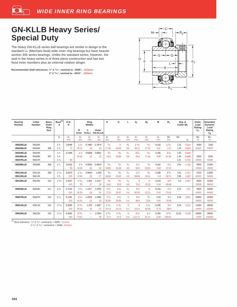
164
GN-KLLB Heavy Series/Special DutyThe heavy GN-KLLB series ball bearings are similar in design to thestandard LL (Mechani-Seal) wide inner ring bearings but have heaviersection 300 series bearings. Unlike the standard series, however, theseal in the heavy series is of three-piece construction and has twofixed inner members plus an external rotation slinger.
Recommended shaft tolerances: 1⁄8"-1 15⁄16", nominal to -.0005", -.013mm;
2"-2 15⁄16", nominal to -.0010", -.025mm.
Bearing Collar Basic Bore (1) O.D. Ring S G L d 1 B2 M B1 Brg. & Static ExtendedNumber Number Outer d D Widths Collar Wt. Load Dynamic
Ring Rating LoadSize B C Outer Co Rating
Inner N-KLL GN-KLLB CE
in. in. in. in. in. in. in. in. in. in. in. lbs lbs lbs lbsmm mm mm mm mm mm mm mm mm mm mm kg N N
GN102KLLB SN102K 1 1⁄8 2.8346 1 7⁄16 0.7480 0.7874 11⁄16 3⁄4 5⁄32 1 15⁄16 11⁄16 0.142 1 31⁄32 1.22 0.554 3550 7500GN103KLLB SN103K 306 1 3⁄16 72 36.51 19 20 17.46 19.05 3.9 49.21 17.46 3.61 1.97 1.33 0.604 15600 33500
GN104KLLB SN104K 1 1⁄4 3.1496 1 1⁄2 0.8268 0.8661 23⁄32 25⁄32 5⁄32 2 3⁄16 11⁄16 0.156 2 1⁄32 1.43 0.649GN106KLLB SN106K 307 1 3⁄8 38.10 21 22 18.3 19.84 3.9 55.6 17.46 3.96 51.59 1.54 0.699 4500 9150GN107KLLB SN107K 1 7⁄16 80 1.61 0.731 20000 40500
GN108KLLB SN108K 308 1 1⁄2 3.5433 1 5⁄8 0.9055 0.9843 25⁄32 27⁄32 3⁄16 2 1⁄2 13⁄16 0.182 2 1⁄4 2.54 1.153 5600 1100090 41.28 23 25 19.84 21.43 4.8 63.5 20.64 4.62 57.15 24500 49000
GN111KLLB SN111K 309 1 11⁄16 3.9370 1 11⁄16 0.9843 1.063 25⁄32 29⁄32 3⁄16 2 3⁄4 13⁄16 0.189 2 5⁄16 3.21 1.457 6700 13200GN112KLLB SN112K 1 3⁄4 100 42.86 25 27 19.84 23.02 4.8 69.85 20.64 4.8 58.74 3.65 1.657 30000 58500
GN115KLLB SN115K 310 1 15⁄16 4.3307 1 31⁄32 1.063 1.1417 31⁄32 31⁄32 3⁄16 3 7⁄8 0.203 2 5⁄8 4.2 1.907 8000 15300110 50 27 29 24.6 24.6 4.8 76.2 22.23 5.16 66.68 35500 68000
GN203KLLB SN203K 311 2 3⁄16 4.7244 2 3⁄16 1.1417 1.2205 1 3⁄32 1 5⁄32 3⁄16 3 1⁄4 7⁄8 0.216 2 7⁄8 5.22 2.37 9500 18000120 55.56 29 31 27.8 29.37 4.8 82.55 22.23 5.49 73.02 41500 80000
GN207KLLB SN207K 312 2 7⁄16 5.1181 2 7⁄16 1.2205 1.2992 1 7⁄32 1 7⁄32 1⁄4 3 1⁄2 15⁄16 0.23 3 1⁄8 6.26 2.841 10800 20400130 61.91 31 33 30.96 30.96 6.4 88.9 23.8 5.84 79.38 48000 90000
GN211KLLB SO211K 314 2 11⁄16 5.9055 2 11⁄16 1.378 1.4567 1 11⁄32 1 11⁄32 1⁄4 4 1 1⁄16 0.265 3 1⁄2 9.94 4.512 14300 26000150 68.26 35 37 34.13 34.13 6.4 101.6 26.99 6.73 88.9 63000 116000
GN215KLLB SN215K 315 2 15⁄16 6.2992 2 15⁄16 — 1.5354 1 15⁄32 1 15⁄32 1⁄4 4 7⁄16 1 1⁄4 0.255 3 15⁄16 12.42 5.638 16000 28500160 74.61 — 39 37.3 37.3 6.4 112.71 31.75 6.48 100.01 71000 125000
(1) Bore tolerance : 1⁄2"-2 3/16", nominal to +.0005, .013mm
2 7⁄16"-2 15⁄16", nominal to +.0006, .015mm
d1
C
d
B1
B2
L
S
B
D G
M
WIDE INNER RING BEARINGS

165
Tri-Ply Seal Industrial SeriesNon-Relubricatable andRelubricatable Types
TO ORDER, SPECIFY BEARING NUMBER FOLLOWED BY “AND COLLAR”. EXAMPLE: G1115KPPB3 AND COLLAR.
Bearing Basic Bore (1) O.D. Ring L d 1 B2 S B1 M(2) F1 O Brg. & Static ExtendedNumber Outer d D Widths Collar Wt. Load Dynamic
Ring Rating LoadSize B C Co Rating
Inner Outer CE
Relubricatable Non-Relubricatable in. in. in. in. in. in. in. in. in. in. in. in. lbs lbs lbsType Type mm mm mm mm mm mm mm mm mm mm mm mm kg N N
G1013KPPB3 1013KPPB3 13⁄16 0.63 0.286G1014KPPB3 1014KPPB3 205 7⁄8 2.0472 1 3⁄8 0.591 5⁄32 1 1⁄2 17⁄32
11⁄16 1 3⁄4 0.142 1.779 0.656 0.60 0.272 1560 3450G1015KPPB3 1015KPPB3 15⁄16 52 34.92 15 3.9 38.1 13.5 17.5 44.4 3.61 45.19 16.66 0.56 0.254 6950 15600G1100KPPB3 1100KPPB3 1 0.51 0.231GE25KPPB3 E25KPPB3 25 0.51 0.231
G1101KPPB3 1101KPPB3 1 1⁄16 0.91 0.413G1102KPPB3 1102KPPB3 1 1⁄8 2.4409 1 7⁄16 0.709 5⁄32 1 3⁄4 5⁄8 23⁄32 1 29⁄32 0.156 2.068 0.849 0.89 0.404 2280 4800G1103KPPB3 1103KPPB3 206 1 3⁄16 62 36.51 18 3.9 44.4 15.9 18.3 48.4 4.19 52.53 21.56 0.83 0.376 10000 21600G1103KPPB4 1103KPPB4 1 1⁄4 0.77 0.349GE30KPPB3 E30KPPB3 30 0.83 0.376
G1104KPPB2 1104KPPB2 1 1⁄4 1.44 0.653G1105KPPB2 1105KPPB2 207 1 5⁄16 2.8346 1 31⁄64 0.748 5⁄32 2 1⁄8 43⁄64 0.742 2 1⁄64 0.145 2.376 1.00 1.33 0.603 3050 6400G1106KPPB2 1106KPPB2 1 3⁄8 72 37.70 19 3.9 54.0 17.1 18.85 51.2 3.68 60.35 25.40 1.26 0.572 13700 28500G1107KPPB2 1107KPPB2 1 7⁄16 1.20 0.544GE35KPPB2 E35KPPB2 35 1.26 0.572
G1108KPPB3 1108KPPB3 1 1⁄2 3.1496 1 11⁄16 0.827 3⁄16 2 3⁄8 23⁄3227⁄32 2 7⁄32 0.223 2.669 0.923 1.74 0.789 4000 8150
G1109KPPB3 1109KPPB3 208 1 9⁄16 80 42.86 21 4.8 60.3 18.3 21.4 56.4 5.66 67.79 23.44 1.63 0.739 17600 36000GE40KPPB3 E40KPPB3 40 1.63 0.739
G1110KPPB4 1110KPPB4 1 5⁄8 1.98 0.898G1111KPPB4 1111KPPB4 209 1 11⁄16 3.3465 1 11⁄16 0.866 3⁄16 2 1⁄2 23⁄32
27⁄32 2 7⁄32 0.179 2.852 1.082 1.87 0.848 4000 8150G1112KPPB4 1112KPPB4 1 3⁄4 85 42.86 22 4.8 63.5 18.3 21.4 56.4 4.55 72.44 27.48 1.82 0.826 17600 36000GE45KPPB4 E45KPPB4 45 1.82 0.826
G1113KPPB3 1113KPPB3 1 13⁄16 2.46 1.116G1114KPPB3 1114KPPB3 1 7⁄8 3.5433 1 15⁄16 0.906 3⁄16 2 3⁄4 23⁄32
31⁄32 2 15⁄32 0.185 3.059 1.083 2.28 1.034 4500 8800G1115KPPB3 1115KPPB3 210 1 15⁄16 90 49.21 23 4.8 69.9 18.3 24.6 62.7 4.7 77.7 27.51 2.24 1.016 19600 39000GE50KPPB3 E50KPPB3 50 2.24 1.016
G1200KPPB4 1200KPPB4 2 3.49 1.583G1201KPPB4 1201KPPB4 2 1⁄16 3.9370 2 3⁄16 0.945 3⁄16 3 13⁄16 1 3⁄32 2 13⁄16 0.213 3.432 1.142 3.24 1.47 5600 10800G1202KPPB4 1202KPPB4 211 2 1⁄8 100 55.56 24 4.8 76.2 20.6 27.8 71.4 5.41 87.17 29.01 3.10 1.406 25000 48000G1203KPPB4 1203KPPB4 2 3⁄16 3.01 1.365GE55KPPB4 E55KPPB4 55 3.01 1.365
(1) Bore tolerance : 13⁄16"-2 3⁄16", nominal to +.0005, .013mm
(2) Applies to Relubricatable type only. Note: Recommended max speed- 500 rpm.
FS
BC
d1
B
L
O
2
D
1
d
B
1 d
S
BC
d1
B
L
M
O
2
D
1
F
B
1
WIDE INNER RING BEARINGS
The non-relubricatable Tri-Ply Seal bearings are dimensionallyinterchangeable with KRRB bearings and can be used with standardhousings. The one piece Tri-Ply seals incorporate a highly effectiveseal design molded to an exterior shroud cap. The shroud cap protectsthe seal lip from fiber wrap and abrasion. These bearings, suppliedwith a self-locking collar, are most effective in environments of severecontamination and moisture.
The relubricatable Tri-Ply Seal bearings are dimensionallyinterchangeable with G-KRRB bearings and can be used with standardhousings.
Recommended shaft tolerances: a. heavy loads nominal to -.001", -.025mm;
b. light loads- nominal to -.002", -.050mm.

166
GC-KRRB Industrial SeriesConcentric CollarRelubricatable Type
TO ORDER, SPECIFY BEARING NUMBER . Example: GC1103KRRB (Concentric collar is assembled with bearing.)
Bearing Basic Bore (1) O.D. Ring S S 1 d1 M O Setscrew Brg. & Static ExtendedNumber Outer d D Widths Size Collar Wt. Load Dynamic
Ring Rating LoadSpherical Size B C Co Rating
O.D. Inner Outer CE
in. in. in. in. in. in. in. in. in. in. lbs lbs lbsmm mm mm mm mm mm mm mm mm kg N N
GC1008KRRB 1⁄2 0.34 0.154GC1010KRRB 203 5⁄8 1.5748 1 3⁄64 0.472 7⁄16 39⁄64 11⁄32 0.107 0.579 10-32 0.32 0.145 1000 2360GC1011KRRB 11⁄16 40 26.59 12 11.1 15.5 34.1 2.72 14.71 M5x0.8 0.27 0.122 4400 10600GCE17KRRB 17 0.27 0.122
GC1012KRRB 204 3⁄4 1.8504 1 7⁄32 0.551 31⁄6447⁄64 1 1⁄2 0.135 0.814 10-32 0.45 0.204 1400 3200
GCE20KRRB 20 47 30.96 14 12.3 18.7 38.1 3.43 20.68 M5x0.8 0.45 0.204 6200 14300
GC1014KRRB 205 7⁄8 0.6 0.272GC1015KRRB 15⁄16 2.0472 1 11⁄32 0.5905 35⁄64
51⁄64 1 3⁄4 0.142 0.777 1⁄4-28 0.56 0.254 1560 3450GC1100KRRB 1 52 34.13 15 13.9 20.2 44.4 3.61 19.74 M6x1 0.51 0.231 6950 15600GCE25KRRB 25 0.51 0.231
GC1102KRRB 206 1 1⁄8 0.89 0.404GC1103KRRB 1 3⁄16 2.4409 1 15⁄32 0.709 37⁄64
57⁄64 2 1⁄16 0.156 0.965 1⁄4-28 0.83 0.376 2280 4800GC1103KRRB3 1 1⁄4 62 37.31 18 14.7 22.6 52.4 4.19 24.51 M6x1 0.77 0.349 10000 21600GCE30KRRB 30 0.83 0.376
GC1104KRRB 1 1⁄4 1.44 0.653GC1106KRRB 207 1 3⁄8 2.8346 1 5⁄8 0.7481 5⁄8 1 2 11⁄32 0.145 1.018 1⁄4-28 1.26 0.572 3050 6400GC1107KRRB 1 7⁄16 72 41.28 19 15.9 25.4 59.5 3.68 25.86 M6x1 1.20 0.544 13700 28500GCE35KRRB 35 1.26 0.572
GC1108KRRB 208 1 1⁄2 3.1496 1 47⁄64 0.827 21⁄32 1 5⁄64 2 11⁄16 0.223 1.119 5⁄16-24 1.74 0.789 4000 8150GCE40KRRB 40 80 44.05 21 16.7 27.4 68.3 5.66 28.42 M8x1.25 1.63 0.739 17600 36000
GC1110KRRB 1 5⁄8 1.98 0.898GC1111KRRB 209 1 11⁄16 3.3465 1 27⁄32 0.866 1 11⁄16 1 5⁄32 2 7⁄8 0.179 1.268 5⁄16-24 1.87 0.848 4000 8150GC1112KRRB 1 3⁄4 85 46.83 22 17.5 29.4 73 4.55 32.21 M8x1.25 1.82 0.826 17600 36000GCE45KRRB 45 1.82 0.826
GC1115KRRB 210 1 15⁄16 3.5433 1 29⁄32 0.906 23⁄32 1 3⁄16 3 1⁄8 0.185 1.269 5⁄16-24 2.18 0.990 4500 8800GCE50KRRB 50 90 48.42 23 18.3 30.2 79.4 4.7 32.23 M8x1.25 2.18 0.990 19600 39000
GC1200KRRB 2 3.9370 2 1⁄8 0.945 13⁄16 1 5⁄16 3 1⁄2 0.213 1.328 3⁄8-24 3.35 1.52 5630 10800GC1203KRRB 211 2 3⁄16 100 53.97 24 20.6 33.3 88.9 5.41 33.73 M10x1.5 2.88 1.306 25000 48000GCE55KRRB 55 2.88 1.306
GC1207KRRB 212 2 7⁄16 4.3307 2 3⁄8 1.063 29⁄32 1 15⁄32 3 3⁄4 0.202 1.379 3⁄8-24 3.45 1.565 6950 13200GCE60KRRB 60 110 60.32 27 23.0 37.3 95.3 5.13 35.03 M10x1.5 31000 58500
GC1215KRRB 215 2 15⁄16 5.1181 2 25⁄32 1.142 1 1⁄16 1 23⁄32 4 1⁄2 0.219 1.506 3⁄8-20 5.82 2.64 8500 15300GCE75KRRB 75 130 70.64 29 27.0 43.7 114.3 5.59 38.25 M10x1.5 37500 68000
(1) Bore tolerances: 1 3⁄16"-2 3/16" nominal to +.0005, .013mm;
2 1⁄4"-3 3⁄16" nominal to +.0006", .015mm.
B
S
M
d
C
S11 D
d
O
WIDE INNER RING BEARINGS
The GC-KRRB wide inner ring bearings are relubricatable withspherical outside diameters and shroud seals. The metal shroudmaintains tight seal contact against the inner ring and shields therubber seals from damage due to dirt fiber wrap.
The concentric collar is locked to the shaft by two setscrews,located 120° apart, which are mated with threaded holes in the collarand drilled holes in the bearing inner ring. The extra-wide designprovides additional shaft support and extra large grease capacity.
Recommended shaft tolerances: 1⁄2"-1 15/16", nominal to -.0005", -.013mm ;
2"-2 15⁄16", nominal to -.0010", -.025mm .

167
GY-KRRB SetscrewIndustrial SeriesThis “Y” series extra wide inner ring setscrew bearing has increasedshaft support for HVAC and other industrial applications. The bearingsfeature superfinished raceways, grade 10 balls, and antiback-out nylonpatch setscrews. They are factory prelubricated and are relubricatable.Setscrew mounting feature is ideal for reversing load applications.
Bearing Basic Bore O.D. Ring S S 1 F M J Setscrew Static ExtendedNumber Outer d D Widths Size Load Dynamic
Ring Rating LoadSize B C Co Rating
Inner Outer CE
in. in. in. in. in. in. in. in. in. in. lbs lbsmm mm mm mm mm mm mm mm mm mm N N
GY1008KRRB 1⁄2GY1009KRRB 203 9⁄16 1.5748 1.078 0.472 0.453 0.625 0.9 0.107 0.179 10-32 1000 2360GY1010KRRB 5⁄8 40 27.38 12 11.5 15.88 22.86 2.72 4.55 M5X.8 4400 10600GY1011KRRB 11⁄16
GYE15KRRB 15GYE17KRRB 17
GY1012KRRB 204 3⁄4 1.8504 1.219 0.55 0.5 0.719 1.085 0.135 0.202 10-32 1400 3200GYE20KRRB 20 47 30.96 14 12.7 18.26 27.56 3.43 5.13 M5X.8 6200 14300
GY1013KRRB 13⁄16
GY1014KRRB 7⁄8 2.0472 1.343 0.591 0.562 0.781 1.332 0.152 0.248 1⁄4-28 1560 3450GY1015KRRB 205 15⁄16 52 34.11 15 14.27 19.91 33.83 3.86 6.3 M6X1 6950 15600GY1100KRRB 1GYE25KRRB 25
GY1101KRRB 1 1⁄16
GY1102KRRB 206 1 1⁄8 2.4409 1.500 0.709 0.625 0.875 1.587 0.156 0.300 1⁄4-28 2280 4800GY1103KRRB 1 3⁄16 62 38.1 18 15.88 22.22 40.31 3.96 7.62 M6X1 10000 21600GY1103KRRB3 1 1⁄4GYE30KRRB 30
GY1104KRRB 1 1⁄4GY1105KRRB 207 1 5⁄16 2.8346 1.688 0.748 0.688 1 1.816 0.145 0.308 5⁄16-24 3050 6400GY1106KRRB 1 3⁄8 72 42.87 19 17.48 25.4 46.18 3.68 7.82 M8X1.25 13700 28500GY1107KRRB 1 7⁄16
GYE35KRRB 35
GY1108KRRB 208 1 1⁄2 3.1496 1.938 0.827 0.75 1.188 2.058 0.16 0.315 5⁄16-24 4000 8150GY1109KRRB 1 9⁄16 80 49.22 21 19.05 30.17 52.27 4.06 8 M8X1.25 17600 36000GYE40KRRB 40
GY1110KRRB 1 5⁄8GY1111KRRB 209 1 11⁄16 3.3465 1.938 0.8661 0.75 1.188 2.28 0.179 0.315 5⁄16-24 4000 8150GY1112KRRB 1 3⁄4 85 49.22 22 19.05 30.17 57.92 4.55 8 M8X1.25 17600 36000GYE45KRRB 45
GY1113KRRB 1 13⁄16
GY1114KRRB 1 7⁄8 3.5433 2.031 0.8661 0.75 1.281 2.474 0.185 0.394 3⁄8-24 4500 8800GY1115KRRB 210 1 15⁄16 90 51.59 22 19.05 32.54 62.84 4.7 10 M10X1.5 19600 39000GY1115KRRB2 2GYE50KRRB 50
GY1200KRRB 2GY1201KRRB 211 2 1⁄16 3.9370 2.187 0.945 0.875 1.312 2.747 0.197 0.394 3⁄8-24 5600 10800GY1202KRRB 2 1⁄8 100 55.55 24 22.22 33.32 69.77 5 10 M10X1.5 25000 48000GY1203KRRB 2 3⁄16
GYE55KRRB 55
GY1204KRRB 2 1⁄4GY1205KRRB 212 2 5⁄16 4.3307 2.562 1.063 1 1.562 3.011 0.202 0.394 3⁄8-24 6950 13200GY1206KRRB 2 3⁄8 110 65.07 27 25.4 39.67 76.48 5.13 10 M10X1.5 31000 58500GY1207KRRB 2 7⁄16
GYE60KRRB 60
GY1210KRRB 2 5⁄8 4.9213 2.75 1.102 1.062 1.687 3.422 0.2 0.472 7⁄16-20 8500 15600GY1211KRRB 214 2 11⁄16 125 69.85 28 26.97 42.84 86.92 5.08 12 M12X1.75 37500 69500GYE70KRRB 70
GY1212KRRB 2 3⁄4GY1214KRRB 215 2 7⁄8 5.1181 3.063 1.142 1.312 1.75 3.619 0.219 0.472 7⁄16-20 8500 15300GY1215KRRB 2 15⁄16 130 77.8 29 33.32 44.45 91.92 5.56 12 M12X1.75 37500 68000GYE75KRRB 75
(1) Bore tolerances: 1⁄2"-2 3/16" nominal to +.0005, .013mm;
2 1⁄4"-3 15⁄16" nominal to +.0006",.015mm.
FD
CJ
B
S1S
d
M
WIDE INNER RING BEARINGS

168
WIDE INNER RING BEARINGS
Bearing Basic d D Ring S S1 F J D1 K1 T M R Setscrew Bearing CrossNumber Outer Bore(1) O.D. Widths Size Wt. Reference
Ring Number (2)
B CInner Outer
in. in. in. in. in. in. in. in. in. in. in. in. in. in. lbs.mm mm mm mm mm mm mm mm mm mm mm mm mm kg
ER08 1⁄2 0.42 0.190 GC1008KRRG-2ER10 204 5⁄8 1.8504 1 7⁄32 5⁄8 1⁄2 23⁄32 1 7⁄64 13⁄64 2 1⁄16 11⁄64 3⁄64 5⁄32 3⁄64 10 - 32 0.37 0.167 GC1010KRRG-2ER12 3⁄4 47 30.96 15.88 12.7 18.26 28.17 5.16 52.4 4.36 1.2 3.97 1.19 M5X.8 0.31 0.141 GC1012KRRG-2
ER14 7⁄8 0.48 0.218 GC1014KRRG-2ER15 205 15⁄16 2.0472 1 11⁄32 3⁄4 9⁄16 25⁄32 1 21⁄64 1⁄4 2 17⁄64 11⁄64 3⁄64 9⁄64 7⁄64 1⁄4 - 28 0.43 0.195 GC1015KRRG-2ER16 1 52 34.13 19.05 14.29 19.84 33.73 6.35 57.5 4.36 1.2 3.57 2.78 M6X1 0.40 0.181 GC1100KRRG-2
ER18 206 1 1⁄8 2.4409 1 1⁄2 7⁄8 5⁄8 7⁄8 1 19⁄32 19⁄64 2 21⁄32 1⁄8 1⁄16 7⁄32 5⁄32 1⁄4 - 28 0.75 0.340 GC1102KRRG-2ER19 1 3⁄16 62 38.1 22.23 15.87 22.22 40.48 7.54 67.5 3.18 1.6 5.56 3.97 M6X1 0.69 0.313 GC1103KRRG-2
ER20 1 1⁄4 1.25 0.567 GC1104KRRG-2ER22 207 1 3⁄8 2.8346 1 11⁄16 15⁄16 11⁄16 1 1 27⁄32 5⁄16 3 5⁄64 11⁄64 1⁄16 7⁄32 15⁄64 5⁄16 - 24 1.10 0.499 GC1106KRRG-2ER23 1 7⁄16 72 42.86 23.81 17.46 25.4 46.83 7.94 78.2 4.36 1.6 5.56 5.95 M8X1.25 1.05 0.476 GC1107KRRG-2
ER24 208 1 1⁄2 3.1496 1 15⁄16 1 3⁄32 3⁄4 1 3⁄16 2 1⁄16 5⁄16 3 13⁄32 1⁄8 1⁄16 1⁄4 23⁄64 5⁄16 - 24 1.48 0.671 GC1108KRRG-280 49.21 27.78 19.05 30.16 52.38 7.94 86.5 3.18 1.6 6.35 9.12 M8X1.25
ER27 209 1 11⁄16 3.3465 1 15⁄16 1 3⁄32 3⁄4 1 3⁄16 2 9⁄32 5⁄16 3 19⁄32 1⁄8 1⁄16 1⁄4 23⁄64 5⁄16 - 24 1.62 0.735 GC1111KRRG-2ER28 1 3⁄4 85 49.21 27.78 19.05 30.16 57.94 7.94 91.3 3.18 1.6 6.35 9.13 M8X1.25 1.52 0.690 GC1112KRRG-2
ER30 210 1 7⁄8 3.5433 2 1⁄32 1 1⁄8 3⁄4 1 9⁄32 2 7⁄16 25⁄64 3 51⁄64 9⁄64 3⁄32 9⁄32 21⁄64 3⁄8 - 24 1.88 0.853 GC1114KRRG-2ER31 1 15⁄16 90 51.59 28.58 19.05 32.54 55.66 9.92 96.4 3.57 2.4 7.14 8.33 M10X1.5 1.84 0.834 GC1115KRRG-2
ER32 211 2 3.9370 2 3⁄16 1 3⁄16 7⁄8 1 5⁄16 2 3⁄4 25⁄64 4 3⁄16 9⁄64 3⁄32 9⁄32 23⁄64 3⁄8 - 24 2.87 1.300 GC1200KRRG-2ER35 2 3⁄16 100 55.56 30.16 22.22 33.34 69.85 9.92 106.4 3.57 2.4 7.14 9.13 M10X1.5 2.39 1.084 GC1203KRRG-2
ER39 212 2 7⁄16 4.3307 2 9⁄16 1 1⁄4 1 1 9⁄16 3 1⁄64 25⁄64 4 37⁄64 1⁄8 3⁄32 17⁄64 29⁄64 3⁄8 - 24 3.20 1.450 GC1207KRRG-2110 65.09 31.75 25.4 39.69 76.60 9.92 116.3 3.18 2.4 6.75 11.51 M10X1.5
ER47 215 2 15⁄16 5.1180 3 1⁄16 1 1⁄2 1 5⁄16 1 3⁄4 3 39⁄64 15⁄32 5 1⁄2 11⁄32 7⁄64 1⁄4 7⁄16 7⁄16 - 20 4.88 2.210 GC1215KRRG-2130 77.79 38.1 33.33 44.45 91.68 11.91 139.7 8.73 2.8 6.35 11.11 M12X1.75
ER51 216 3 3⁄16 5.5110 3 1⁄16 1 11⁄16 1 1⁄8 1 15⁄16 3 7⁄8 17⁄32 5 57⁄64 3⁄16 7⁄64 7⁄16 35⁄64 7⁄16 - 20 7.61 3.450 GC1216KRRG-2140 77.79 42.86 28.58 49.21 98.43 13.49 149.6 4.76 2.8 11.11 13.89 M12X1.75
(1)Bore tolerance: 1⁄2"-2 3⁄16", nominal to +.0005", .013mm2 1⁄4"-2 15⁄16", nominal to +.0006", .015mm
(2)Use Cross Reference Bearing Numbers to locate Load Ratings on page 155.
ER Industrial SeriesRelubricatable TypeThis series offers industry standard mounting dimensions andstandard nomenclature. ER bearings are designed with a uniquesetscrew locking device that locks bearing to shaft and resistsloosening during operation.
Positive contact land-riding R-seals provide protection againstharmful contaminants and retain lubricant.
ER bearings are black oxide coated for corrosion resistance.
Recommended shaft tolerances: 1⁄2"-1 15⁄16", nominal to -.0005", -.013mm;2"-2 15⁄16", nominal to -.0010", -.025mm.
dD F
K
J
M
C
RT
D
B
S S1
1
1
TO ORDER, SPECIFY BEARING NUMBER, Example: ER08.

169
SM Industrial SeriesA and B Types/MUA-B Inserts (6)
TO ORDER, SPECIFY BEARING NUMBER FOLLOWED BY “AND COLLAR”. EXAMPLE: SM1207KB AND COLLAR.
Bearing Number Collar Basic Bore (4) O.D. Ring S&G F L d 1 B2 B1 Brg. & Static ExtendedNumber Outer d D Widths Collar Wt. Load Dynamic
Ring Rating LoadSize B C Co Rating
A Type (7) B Type Inner Outer CE
in. in. in. in. in. in. in. in. in. in. lbs lbs lbsmm mm mm mm mm mm mm mm mm kg N N
SM1008K SM1008KB S1008K 1⁄2 0.32 0.145SM1009K SM1009KB S1009K 203 9⁄16 1.5748 1 3⁄32 0.4724 35⁄64 0.900 5⁄32 1 1⁄8 17⁄32 1 15⁄32 0.29 0.131 1000 2360SM1010K SM1010KB S1010K 5⁄8 40 27.78 12 13.9 22.86 4.0 28.6 13.5 37.3 0.3 0.136 4400 10600SM1011K SM1011KB S1011K 11⁄16 0.25 0.113
SM1012K SM1012KB S1012K 204 3⁄4 1.8504 1 11⁄32 0.5512 43⁄64 1.085 5⁄32 1 5⁄16 17⁄32 1 23⁄32 0.43 0.195 1400 320047 34.13 14 17.1 27.56 4.0 33.3 13.5 48.66 6200 14300
SM1013K SM1013KB S1013K 13⁄16 0.61 0.276SM1014K SM1014KB S1014K 205 7⁄8 2.0472 1 3⁄8 0.5906 11⁄16 1.332 5⁄32 1 1⁄2 17⁄32 1 3⁄4 0.56 0.254 1560 3450SM1015K SM1015KB S1015K 15⁄16 52 34.93 15 17.5 33.83 4.0 38.1 13.5 44.45 0.52 0.236 6950 15600SM1100K SM1100KB S1100K 1 0.48 0.217
SM1101K SM1101KB S1101K 1 1⁄16 2.4409 1 7⁄16 0.6299 23⁄32 1.587 5⁄32 1 3⁄4 5⁄8 1 29⁄32 0.88 0.399 2280 4800SM1102K SM1102KB S1102K 206 1 1⁄8 62 36.51 16
(1)18.3 40.31 4.0 44.4 15.9 48.4 0.81 0.367 10000 21600
SM1103K SM1103KB S1103K 1 3⁄16 0.73 0.331
SM1104K SM1104KB S1104K 1 1⁄4 1.37 0.621SM1105K SM1105KB S1105K 207 1 5⁄16 2.8346 1 31⁄64 0.6693 0.742 1.816 5⁄32 2 1⁄8 11⁄16 2 1⁄64 1.3 0.589 3050 6400SM1106K SM1106KB S1106K 1 3⁄8 72 37.70 17
(2)18.85 46.13 4.0 54.0 17.46 51.2 1.24 0.562 13700 28500
SM1107K SM1107KB S1107K 1 7⁄16 1.19 0.539
SM1108KT SM1108KB S1108KT 208 1 1⁄2 3.1496 1 11⁄16 0.7087 27⁄32 2.058 3⁄16 2 3⁄8 23⁄32 2 7⁄32 1.68 0.761 4000 8150SM1109KT S1109KT 1 9⁄16 80 42.86 18
(3)21.4 52.27 4.8 60.3 18.3 56.4 1.58 0.716 17600 36000
SM1110K SM1110KB S1110K 1 5⁄8 3.3465 1 11⁄16 0.7480 27⁄32 2.28 3⁄16 2 1⁄2 23⁄32 2 7⁄32 1.93 0.875 4000 8150SM1111K SM1111KB S1111K 209 1 11⁄16 85 42.86 19 21.4 57.92 4.8 63.5 18.3 56.4 1.89 0.857 17600 36000SM1112K SM1112KB S1112K 1 3⁄4 1.77 0.803
SM1113K SM1113KB S1113K 1 13⁄16 3.5433 1 15⁄16 0.7874 31⁄32 2.474 3⁄16 2 3⁄4 23⁄32 2 15⁄32 2.37 1.075 4500 8800SM1114K SM1114KB S1114K 210 1 7⁄8 90 49.21 20 24.6 62.84 4.8 69.9 18.3 62.7 2.23 1.012 19600 39000SM1115K SM1115KB S1115K 1 15⁄16 2.12 0.962
SM1200K SM1200KB S1200K 2 3.33 1.51SM1201K SM1201KB S1201K 211 2 1⁄16 3.9370 2 3⁄16 0.8268 1 3⁄32 2.747 3⁄16 3 13⁄16 2 13⁄16 3.08 1.397 5600 10800SM1202K SM1202KB S1202K 2 1⁄8 100 55.56 21 27.8 69.77 4.8 76.2 20.6 71.4 3.17 1.438 25000 48000SM1203K SM1203KB S1203K 2 3⁄16 2.77 1.256
SM1204K SM1204KB S1204K 212 2 1⁄4 4.1 1.86SM1205K SM1205KB S1205K 2 5⁄16 4.3307 2 7⁄16 0.8661 1 7⁄32 3.011 1⁄4 3 5⁄16 7⁄8 3 1⁄16 3.94 1.787 6950 13200SM1206K SM1206KB S1206K 2 3⁄8 110 61.91 22 30.96 76.48 6.4 84.14 22.33 77.8 3.73 1.692 31000 58500SM1207K SM1207KB S1207K 2 7⁄16 3.03 1.374
SM1208K SM1208K S1208K 213 2 1⁄2 4.7244 2 11⁄16 0.9055 1 11⁄32 3.33 1⁄4 3 13⁄16 15⁄16 3 3⁄8 5.45 2.472 7800 14300120 68.26 23 34.13 84.58 6.4 96.84 23.81 85.73 34000 63000
SM1211KT SM1211KTB S1211KT 214 2 11⁄16 4.9213 2 11⁄16 0.9449 1 11⁄32 3.422 1⁄4 3 13⁄1615⁄16 3 3⁄8 5.33 2.418 8500 15600
125 68.26 24 34.13 86.92 6.4 96.84 23.81 85.73 37500 69500
SM1213K SM1213KB S1213K 215 2 13⁄16 5.1181 2 15⁄16 0.9843 1 15⁄32 3.619 1⁄4 4 15⁄16 3 5⁄8 6.3 2.858 8500 15300SM1215K SM1215KB S1215K 2 15⁄16 130 74.61 25 37.3 91.92 6.4 101.6 23.81 92.08 6.18 2.803 37500 68000
SM1303K SM1303KB S1303K 216 3 3⁄16 5.5118 3 3⁄16 1.0236 1 19⁄32 3.874 1⁄4 4 3⁄8 1 3 15⁄16 7.61 3.452 10200 18000140 80.96 26 40.48 98.4 6.4 111.13 25.4 100.01 45000 80000
SM1307K SM1307KB S1307K 217 3 7⁄16 5.9055 3 7⁄16 1.1024 1 23⁄32 4.127 1⁄4 4 7⁄16 1 4 3⁄16 8.6 3.901 11800 20800150 87.31 28 43.66 104.83 6.4 112.71 25.4 106.36 52000 93000
SM1311W-BR SM1311WB-BR(5) S1311K 219 3 11⁄16 6.6929 3 11⁄16 1.2598 1 27⁄32 4.659 1⁄4 5 1 1⁄16 4 1⁄2 13.4 6.078 22000 34000170 93.66 32 46.83 118.34 6.4 127 26.99 114.3 98000 150000
SM1315W-BR SM1315WB-BR(5) S1315 220 3 15⁄16 7.0866 3 15⁄16 1.3386 1 31⁄32 4.876 1⁄4 5 1⁄2 1 1⁄4 4 15⁄16 16.17 7.335 25000 38000180 100.01 34 50 123.85 6.4 139.7 31.75 125.41 110000 170000
(1) Spherical O.D. outer ring width is .7087", 18mm
(4) Bore tolerance: 1⁄2"-2 3⁄16", nominal to +.0005, +.013mm
(2) Spherical O.D. outer ring width is .7480", 19mm 2 1⁄4"-3 3⁄16", nominal to +.0006, +.015mm
(3) Spherical O.D. outer ring width is .8268", 21mm 3 1⁄4"- 3 15⁄16", nominal to +.0007", +.018 mm.
d1
C
d
B1
L
S
B
FD
B2
Gd1
C
d
B1
L
S
B
FD
B2
G
A Type B Type
(5)For applications where thrust load exceeds 60% of radialload consult The Torrington Engineering Department.
(6) See page 236.
(7) Order as MUA assembly suggested.
WIDE INNER RING BEARINGS
Standard SM series wide inner ring ball bearings have the same ringtolerances and corner radii as equivalent 200 series single row radialball bearings.
Type A has cylindrical outside diameters; type B has sphericaloutside diameters. The letter B appears on outer ring only. Bearingsare not prelubricated
Recommended shaft tolerances: 1⁄2"-1 15⁄16", nominal to -.0005", -.013mm;
2"-3 15⁄16", nominal to -.0010", -.025mm.

170
SMN Heavy Series A and BTypes/MUOA-B Inserts (4)
Heavy SMN series wide inner ring ball bearings have the same ring tolerancesand corner radii as equivalent 300 series single row radial ball bearings.
Type A has cylindrical outside diameters; type B has spherical outsidediameters. The letter B appears on outer ring only. Bearings are notprelubricated.
Recommended shaft tolerances: 5⁄8"-1 15⁄16", nominal to -.0005", -.013mm;2 3⁄16"-3 15⁄16", nominal to -.0010", -.025mm.
Larger sizes- consult the Engineering department.
d1
C
d
B1
L
S
B
FD G
B2
d1d
B1
L
S
B
FD G
B2C
A Type B Type
TO ORDER, SPECIFY BEARING NUMBER FOLLOWED BY “AND COLLAR”. EXAMPLE: SMN102K AND COLLAR.
Bearing Collar Basic Bore (1) O.D. Ring S G F L d 1 B2 B1 Brg. & Static ExtendedNumber Number Outer d D Widths Collar Wt. Load Dynamic
Ring Rating LoadA Type (3) B Type Size B C Co Rating
Inner Outer CE
in. in. in. in. in. in. in. in. in. in. in. lbs lbs lbsmm mm mm mm mm mm mm mm mm mm mm kg N N
SMN010K SMN010KB SN010K 303 5⁄8 1.8504 1 11⁄32 0.5512 43⁄64 43⁄64 1.021 5⁄32 1 3⁄8 5⁄8 1 13⁄16 0.53 0.24 1460 3350SMN011K SMN011KB SN011K 11⁄16 47 34.13 14 17.07 17.07 25.93 4.0 34.93 15.88 46.05 0.48 0.218 6550 15000
SMN012K SMN012KB SN012K 304 3⁄4 2.0472 1 3⁄8 0.5906 5⁄8 3⁄4 1.151 5⁄32 1 7⁄16 5⁄8 1 27⁄32 0.5 0.227 1760 400052 34.93 15 15.9 19.05 29.24 4.0 36.51 15.88 46.83 7800 17600
SMN013K SMN013KB SN013K 13⁄16 0.98 0.445SMN014K SMN014KB SN014K 305 7⁄8 2.4409 1 3⁄8 0.6693 21⁄32
23⁄32 1.437 5⁄32 1 11⁄165⁄8 1 27⁄32 0.95 0.431 2750 5850
SMN015K SMN015KB SN015K 15⁄16 62 34.93 17 16.67 18.26 36.5 4.0 42.86 15.88 46.83 0.91 0.413 12200 26000SMN100K SMN100KB SN100K 1 0.86 0.404
SMN101K SMN101KB SN101K 1 1⁄16 2.8346 1 7⁄16 0.7480 11⁄163⁄4 1.702 5⁄32 1 15⁄16
11⁄16 1 31⁄32 1.34 0.608 3550 7500SMN102K SMN102KB SN102K 306 1 1⁄8 72 36.51 19 17.46 19.05 43.23 4.0 49.21 17.46 50 1.29 0.585 15600 33500SMN103K SMN103KB SN103K 1 3⁄16 1.25 0.567
SMN104K SMN104KB SN104K 1 1⁄4 1.77 0.803SMN105K SMN105KB SN105K 307 1 5⁄16 3.1496 1 1⁄2 0.8268 23⁄32
25⁄32 1.927 5⁄32 2 3⁄1611⁄16 2 1⁄32 1.67 0.757 4500 9150
SMN106K SMN106KB SN106K 1 3⁄8 80 38.10 21 18.26 19.84 48.95 4.0 55.6 17.46 51.59 1.6 0.726 20000 40500SMN107K SMN107KB SN107K 1 7⁄16 1.56 0.721
SMN108K SMN108KB SN108K 308 1 1⁄2 3.5433 1 5⁄8 0.9055 25⁄32 27⁄32 2.185 3⁄16 2 1⁄2 13⁄16 2 1⁄4 2.4 1.089 5600 11000SMN109K SMN109KB SN109K 1 9⁄16 90 41.28 23 19.84 21.43 55.5 4.8 63.5 20.64 57.15 2.26 1.025 25000 49000
SMN110K SMN110KB SN110K 1 5⁄8 3.9370 1 11⁄16 0.9843 25⁄32 29⁄32 2.443 3⁄16 2 3⁄4 13⁄16 25⁄16 3.16 1.433 6700 13200SMN111K SMN111KB SN111K 309 1 11⁄16 100 42.86 25 19.84 23.02 62.05 4.8 69.9 20.64 58.74 3 1.361 30000 58500SMN112K SMN112KB SN112K 1 3⁄4 3 1.361
SMN113K SMN113KB SN113K 1 13⁄16 4.3307 1 15⁄16 1.063 31⁄3231⁄32 2.708 3⁄16 3 7⁄8 2 5⁄8 4.18 1.896 8000 15300
SMN114K SMN114KB SN114K 310 1 7⁄8 110 49.21 27 24.61 24.61 68.78 4.8 76.2 22.2 66.68 3.98 1.805 35500 68000SMN115K SMN115KB SN115K 1 15⁄16 3.83 1.737
SMN200K SMN200KB SN200K 2 5.32 2.413SMN201K SMN201KB SN201K 311 2 1⁄16 4.7244 2 3⁄16 1.1417 1 3⁄32 1 3⁄32 2.953 3⁄16 3 1⁄4 7⁄8 2 7⁄8 5.28 2.395 9500 18000SMN202K SMN202KB SN202K 2 1⁄8 120 55.56 29 27.78 27.78 75.01 4.8 82.55 22.2 73.03 5.14 2.331 41500 80000SMN203K SMN203KB SN203K 2 3⁄16 4.87 2.209
SMN204K SMN204KB SN204K 312 2 1⁄4 6.8 3.084SMN205K SMN205KB SN205K 2 5⁄16 5.1181 2 7⁄16 1.2205 1 7⁄32 1 7⁄32 3.21 1⁄4 3 1⁄2 15⁄16 3 1⁄8 6.64 3.012 10800 20400SMN206K SMN206KB SN206K 2 3⁄8 130 61.91 31 31 31 81.53 6.4 88.9 23.81 79.38 6.41 2.908 48000 90000SMN207K SMN207KB SN207K 2 7⁄16 6.2 2.812
SMN211K SMN211KB SO211K 314 2 11⁄16 5.9055 2 11⁄16 1.378 1 11⁄32 1 11⁄32 3.731 1⁄4 4 1 1⁄16 3 5⁄8 9.27 4.205 14300 26000150 2.69 35 34.13 34.13 94.78 6.4 101.6 26.99 92.08 63000 116000
SMN215K SMN215KB SN215K 315 2 15⁄16 6.2992 2 15⁄16 1.4567 1 15⁄32 1 15⁄32 3.952 1⁄4 4 7⁄16 1 1⁄4 3 15⁄16 12.91 5.856 16000 28500160 74.61 37 37.31 37.31 100.38 6.4 112.71 31.75 100.01 71000 125000
SMN303K SMN303KB SN303K 316 3 3⁄16 6.6929 3 3⁄16 1.5354 1 19⁄32 1 19⁄32 4.209 1⁄4 4 11⁄16 1 1⁄4 4 3⁄16 14.78 6.704 18000 30500170 80.96 39 40.48 40.48 106.91 6.4 119.06 31.75 106.36 80000 137000
SMN307K SMN307KB SN307K 318 3 7⁄16 7.4803 3 7⁄16 1.6929 1 23⁄32 1 23⁄32 4.729 5⁄16 5 1⁄4 1 7⁄16 4 9⁄16 22.01 9.984 22400 35500190 87.31 43 43.66 43.66 120.12 7.94 133.35 36.51 115.89 98000 156000
SM0311W-BR(2)
SM0311WB-BR(2)
SO311K 319 3 11⁄16 7.874 3 11⁄16 1.7717 1 17⁄32 2 5⁄32 4.987 5⁄16 5 1⁄2 1 7⁄16 4 13⁄16 24.45 11.09 37500 50000200 93.66 45 38.89 54.77 126.67 7.94 139.7 36.51 122.24 166000 224000
SMN315K SMN315KB SN315K 320 3 15⁄16 8.4646 3 15⁄16 1.8504 1 31⁄32 1 31⁄32 5.306 5⁄16 5 3⁄4 1 7⁄16 5 1⁄16 28.81 13.068 29000 43000215 100.01 47 50 50 134.77 7.94 146.05 36.51 128.59 132000 193000
SMN403W-BR(2)
SMN403WB-BR SN403K 321 4 3⁄16 8.8583 4 1⁄8 1.9291 1 29⁄32 2 7⁄32 5.56 5⁄16 6 3⁄16 1 11⁄16 5 1⁄2 34.19 15.508 43000 56000225 104.78 49 48.42 56.36 141.22 7.94 157.16 42.86 139.7 193000 250000
SMN407W-BR(2)
SMN407WB-BR(2)
SN407K 322 4 7⁄16 9.4488 4 3⁄16 1.9685 1 15⁄16 2 1⁄4 5.92 5⁄16 6 1⁄2 1 11⁄16 5 9⁄16 42 19.051 52000 63000240 106.36 50 49.21 57.15 142.75 7.94 165.1 42.86 141.29 228000 280000
SMN415W-BR(2)
SMN415WB-BR(2)
SN415K 326 4 15⁄16 11.0236 4 3⁄16 2.3228 2 1⁄8 2 7⁄16 6.951 5⁄16 8 1⁄8 1 11⁄16 5 15⁄16 65.39 29.66 69500 78000280 106.36 59 53.98 61.91 176.56 7.94 206.38 42.86 150.81 305000 345000
(1)Bore tolerance: 5⁄8"-2 3⁄16", nominal to +.0005, .013mm
3 1⁄4"- 4 3⁄16", nominal to +.0007", +.018mm.47⁄16"-415⁄16", nominal to +.0008", +.020mm
(2)For applications where thrust load exceeds 60% of radial load consult The Torrington Company.
(3) Order as MUOA assembly suggested.
(4) See page 236.
WIDE INNER RING BEARINGS

171
SM-S Industrial SeriesIn the standard SM-S series, the construction permits the innerassembly to swivel in the outer aligning ring. Unrestricted self-alignment is thus achieved, which allows the inner ring to becomesquare and true with the shaft and assembly. Because the external Sring is specially ground and is closely matched to its respective outerbearing ring, the S ring of one bearing will not fit the outer ring ofanother bearing. Bearings are not prelubricated.
Recommended shaft tolerances: 1"-1 15⁄16", nominal to -.0005", -.013mm;
2"-3 15⁄16", nominal to -.0010", -.025mm.
TO ORDER, SPECIFY BEARING NUMBER FOLLOWED BY “AND COLLAR”. EXAMPLE: SM1215KS AND COLLAR.
Bearing Collar Basic Bore (1) O.D. Ring S&G F L d 1 B2 B1 Brg. & Static ExtendedNumber Number Outer d D Widths Collar Wt. Load Dynamic
Ring Rating LoadSpherical Size B C CO Rating
O.D. Inner Outer CE
in. in. in. in. in. in. in. in. in. in. lbs lbs lbsmm mm mm mm mm mm mm mm mm mm kg N N
SM1100KS S1100K 205S 1 2.2441 1 3⁄8 0.591 11⁄16 1.293 5⁄32 1 1⁄2 17⁄32 1 47⁄64 0.58 0.263 1560 345057 34.93 15 17.46 32.84 4.0 38.1 13.5 44.1 6950 15600
SM1103KS S1103K 206S 1 3⁄16 2.6772 1 7⁄16 0.6300 23⁄32 1.54 5⁄32 1 3⁄4 5⁄8 1 29⁄32 0.92 0.418 2280 480068 36.51 16 18.3 39.12 4.0 44.4 15.9 48.4 10000 21600
SM1104KS S1104K 207S 1 1⁄4 3.1102 1 31⁄64 0.669 0.742 1.816 5⁄32 2 1⁄8 11⁄16 2 1⁄64 1.6 0.726 3050 6400SM1107KS S1107K 1 7⁄16 79 37.70 17 18.85 46.13 4.0 54.4 17.46 51.2 1.45 0.658 13700 28500
SM1108KS S1108KT 208S 1 1⁄2 3.4646 1 11⁄16 0.709 27⁄32 2.058 3⁄16 2 3⁄8 23⁄32 2 7⁄32 1.99 0.903 4000 815088 42.86 18 21.4 52.27 4.8 60.3 18.3 56.4 17600 36000
SM1115KS S1115K 210S 1 15⁄16 3.9370 1 15⁄16 0.7874 31⁄32 2.474 3⁄16 2 3⁄4 23⁄32 2 15⁄32 2.61 1.185 4500 8800100 49.21 20 24.6 62.84 4.8 69.9 18.3 62.7 19600 39000
SM1203KS S1203K 211S 2 3⁄16 4.3307 2 3⁄16 0.8268 1 3⁄32 2.747 3 ⁄16 3 13⁄16 2 13⁄16 3.85 1.748 5600 10800110 55.56 21 27.8 69.77 4.8 76.2 20.6 71.4 25000 48000
SM1207KS S1207K 212S 2 7⁄16 4.7244 2 7⁄16 0.8661 1 7⁄32 3.011 1⁄4 3 5⁄167⁄8 3 1⁄16 4.2 1.907 6950 13200
120 61.91 22 30.96 76.48 6.4 84.14 22.2 77.8 31000 58500
SM1211KS S1211KT 214S 2 11⁄16 5.5118 2 11⁄16 0.9449 1 11⁄32 3.422 1⁄4 3 13⁄1615⁄16 3 3⁄8 6.55 2.974 8500 15600
140 68.26 24 34.13 86.92 6.4 96.84 23.81 79.4 37500 69500
SM1215KS S1215K 215S 2 15⁄16 5.7087 2 15⁄16 0.9843 1 15⁄32 3.619 1⁄4 4 15⁄16 3 5⁄8 7.8 3.541 8500 15300145 74.61 25 37.3 91.92 6.4 101.6 23.81 92.08 37500 68000
SM1303KS S1303K 216S 3 3⁄16 6.1024 3 3⁄16 1.0236 1 19⁄32 3.874 1⁄4 4 3⁄8 1 3 15⁄16 9.14 4.15 10200 18000155 80.96 26 40.48 98.4 6.4 111.13 25.4 100.01 45000 80000
SM1307KS S1307K 217S 3 7⁄16 6.4961 3 7⁄16 1.1024 1 23⁄32 4.127 1⁄4 4 7⁄16 1 4 3⁄16 10.33 4.69 11800 20800165 87.31 28 43.66 104.83 6.4 112.71 25.4 106.36 52000 93000
SM1315WS(2)
S1315K 220S 3 15⁄16 7.874 3 15⁄16 1.3386 1 31⁄32 4.876 1⁄4 5 1⁄2 1 1⁄4 4 15⁄16 19.69 8.939 25000 38000200 100.01 34 50 123.85 6.4 139.7 31.75 125.41 110000 170000
(1) Bore tolerance: 1"-2 3⁄16", nominal to +.0005, .013mm2 1⁄4"-3 3⁄16", nominal to +.0006, .015mm3 1⁄4"- 3 15⁄16", nominal to +.0007", +.018mm.
S G
d
B
F
B2
1
C
Dd
1
LB
(2)For applications where thrust load exceeds 60% of radial load consult The Torrington Company.
WIDE INNER RING BEARINGS
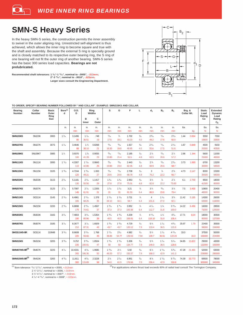
172
SMN-S Heavy SeriesIn the heavy SMN-S series, the construction permits the inner assemblyto swivel in the outer aligning ring. Unrestricted self-alignment is thusachieved, which allows the inner ring to become square and true withthe shaft and assembly. Because the external S ring is specially groundand is closely matched to its respective outer bearing ring, the S ring ofone bearing will not fit the outer ring of another bearing. SMN-S serieshas the basic 300 series load capacities. Bearings are notprelubricated.
Recommended shaft tolerances: 1 3⁄16"-1 15⁄16", nominal to -.0005", -.013mm;2"-3 15⁄16", nominal to -.0010", -.025mm.
Larger sizes consult the Engineering Department.
TO ORDER, SPECIFY BEARING NUMBER FOLLOWED BY “AND COLLAR”. EXAMPLE: SMN215KS AND COLLAR.
Bearing Collar Basic Bore (1) O.D. Ring S G F L d 1 B2 B1 Brg. & Static ExtendedNumber Number Outer d D Widths Collar Wt. Load Dynamic
Ring Rating LoadSize B C Co Rating
Inner Outer CE
in. in. in. in. in. in. in. in. in. in. in. lbs lbs lbsmm mm mm mm mm mm mm mm mm mm kg N N
SMN103KS SN103K 306S 1 3⁄16 3.1496 1 7⁄16 .748 11⁄163⁄4 1.702 5⁄32 115⁄16
11⁄16 131⁄32 1.44 0.654 3550 755080 36.51 19 17.5 19.1 43.23 4.0 49.2 17.5 50.0 15600 33500
SMN107KS SN107K 307S 1 7⁄16 3.4646 1 1⁄2 0.8268 23⁄3225⁄32 1.927 5⁄32 2 3⁄16
11⁄16 2 1⁄32 1.87 0.849 4500 915088 38.10 21 18.30 19.8 48.95 4.0 55.6 17.5 51.6 20000 40500
SMN108KS SN108KT 308S 1 1⁄2 3.9370 1 5⁄8 0.9055 25⁄3227⁄32 2.185 3⁄16 2 1⁄2 13⁄16 2 1⁄4 2.96 1.344 5600 11000
100 41.28 23 19.80 21.4 55.5 4.8 63.5 20.6 57.2 25000 49000
SMN111KS SN111K 309S 1 11⁄16 4.3307 1 11⁄16 0.9843 25⁄3229⁄32 2.443 3⁄16 2 3⁄4 13⁄16 2 5⁄16 3.73 1.693 6700 13200
110 42.86 25 19.80 23.0 62.05 4.8 69.9 20.6 58.7 30000 58500
SMN115KS SN115K 310S 1 15⁄16 4.7244 1 15⁄16 1.063 31⁄3231⁄32 2.708 3⁄16 3 7⁄8 2 5⁄8 4.73 2.147 8000 15300
120 49.21 27 24.6 24.6 68.78 4.8 76.2 22.2 66.7 35500 68000
SMN203KS SN203K 311S 2 3⁄16 5.1181 2 3⁄16 1.1417 1 3⁄32 1 3⁄32 2.953 3⁄16 3 1⁄4 7⁄8 2 7⁄8 6.1 2.769 9500 18000130 55.56 29 27.8 27.8 75.01 4.8 82.6 22.2 73.00 41500 80000
SMN207KS SN207K 312S 2 7⁄16 5.7087 2 7⁄16 1.2205 1 7⁄32 1 7⁄32 3.21 1⁄4 3 1⁄2 15⁄16 3 1⁄8 7.5 3.405 10800 20400145 61.91 31 31 31 81.53 6.4 88.9 23.8 79.4 48000 90000
SMN211KS SO211K 314S 2 11⁄16 6.4961 2 11⁄16 1.378 1 11⁄32 1 11⁄32 3.731 1⁄4 4 1 1⁄16 3 5⁄8 11.42 5.185 14300 26000165 68.26 35 34.10 34.1 94.7 6.4 101.6 27.0 92.1 63000 116000
SMN215KS SN215K 315S 2 15⁄16 6.8898 2 15⁄16 1.4567 1 15⁄32 1 15⁄32 3.952 1⁄4 4 7⁄16 1 1⁄4 3 15⁄16 14.22 6.456 16000 28500
175 74.61 37 37.3 37.3 100.38 6.4 112.7 31.8 100.0 71000 125000
SMN303KS SN303K 316S 3 3⁄16 7.4803 3 3⁄16 1.5354 1 19⁄32 1 19⁄32 4.209 1⁄4 4 11⁄16 1 1⁄4 4 3⁄16 17.71 8.04 18000 30500190 80.96 39 40.5 40.5 106.91 6.4 119.10 31.8 106.4 80000 137000
SMN307KS SN307K 318S 3 7⁄16 8.2677 3 7⁄16 1.6929 1 23⁄32 1 23⁄32 4.729 5⁄16 5 1⁄4 1 7⁄16 4 9⁄16 25.97 1.79 22400 35500210 87.31 43 43.7 43.7 120.12 7.9 133.4 36.5 115.9 98000 156000
SMO311WS-BR SO311K 319WB 3 11⁄16 8.6608 3 11⁄16 1.768 1 17⁄32 2 5⁄32 4.982 5⁄16 5 1⁄2 1 7⁄16 4 13⁄16 33.0 37500 50000
220 93.66 45 38.89 54.77 126.53 7.94 139.7 36.51 122.24 16.3 166000 224000
SMN315KS SN315K 320S 3 15⁄16 9.252 3 15⁄16 1.8504 1 31⁄32 1 31⁄32 5.306 5⁄16 5 3⁄4 1 7⁄16 5 1⁄16 34.85 15.822 29000 43000235 100.01 47 50 50 134.77 7.9 146.0 36.5 128.6 132000 193000
SMN407WS-BR(2) SN407K 322S 4 7⁄16 10.4331 4 3⁄16 1.9685 1 15⁄16 2 1⁄4 5.92 5⁄16 6 1⁄2 1 11⁄16 5 9⁄16 47.28 21.465 52000 63000265 106.36 50 49.20 57.2 150.37 7.9 168.3 42.9 141.3 228000 280000
SMN415WS-BR(2) SN415K 326S 4 15⁄16 11.811 4 9⁄16 2.3228 2 1⁄8 2 7⁄16 6.951 5⁄16 8 1⁄8 1 11⁄16 5 15⁄16 74.39 33.773 69500 78000300 115.89 59 54.0 61.9 176.56 7.9 206.4 42.9 150.8 305000 345000
(1) Bore tolerance: 15⁄16"-2 3⁄16", nominal to +.0005, +.013mm
2 1⁄4"-3 3⁄16", nominal to +.0006, +.015mm3 1⁄4"-4 3⁄16", nominal to +.0007", +.018mm.4 7⁄16"-4 15⁄16", nominal to +.0008", +.020mm.
S G
d
B
F
B2
1
C
Dd
1
LB
(2)For applications where thrust load exceeds 60% of radial load consult The Torrington Company.
WIDE INNER RING BEARINGS

173
WIDE INNER RING BEARINGS
Medium DutyGYM-KRRB InsertsSetscrew LockThe Fafnir GYM-KRRB series is designed to offer extendedbearing life, even in the most demanding industrial environments.This insert features a full width inner ring which provides extrasupport along the shaft. This extra support feature, coupled with aflexible nylon retainer, allows the GYM-KRRB inserts to operate forextended periods with undersized shafts or misalignment condi-tions.
Fafnir’s GYM-KRRB series inserts are equipped witha three-piece seal which protects against corrosion, contaminationand fiber wrap. These inserts also include nylon patch setscrewswhich prevent setscrew back-out and provide superior holdingpower, even in applications with severe vibration.
Bearing Basic Bore O.D. Ring S S1 F M J SetscrewNumber Outer d D Widths
RingSpherical Size B C
O.D. Inner Outer
in. in. in. in. in. in. in. in. in. in.mm mm mm mm mm mm mm mm mm
GYM1100KRRB 206 1 2.4409 1.500 0.709 0.625 0.875 1.587 0.156 0.300 1⁄4 -2862 38.10 18 15.88 22.22 40.31 3.96 7.62 M6 x 1
GYM1103KRRB 207 13⁄16 2.8346 1.688 0.748 0.688 1.000 1.816 0.145 0.308 5⁄16 -2472 42.87 19 17.48 25.40 46.18 3.68 7.82 M8 x 1.25
GYM1107KRRB 208 17⁄16 3.1496 1.938 0.827 0.750 1.188 2.058 0.160 0.315 5⁄16 -2480 49.22 21 19.05 30.17 52.27 4.06 8.00 M8 x 1.25
GYM1108KRRB 209 11⁄2 3.3465 1.938 0.866 0.750 1.188 2.280 0.179 0.315 5⁄16 -2485 49.22 22 19.05 30.17 52.27 4.55 8.00 M8 x 1.25
GYM1111KRRB 210 111⁄16 3.5433 2.031 0.866 0.750 1.281 2.474 0.185 0.394 3⁄8 -24GYM1112KRRB 13⁄4 90 51.59 22 19.05 32.54 62.84 4.70 10.00 M10 x 1.5
GYM1115KRRB 211 115⁄16 3.9370 2.187 0.945 0.875 1.312 2.747 0.197 0.394 3⁄8 -24GY1200KRRB 2 100 55.55 24 22.22 33.32 69.77 5.00 10.00 M10 x 1.5
GYM1203KRRB 212 2 3⁄16 4.3307 2.562 1.063 1.000 1.562 3.011 0.202 0.394 3⁄8 -24GY1204KRRB 21⁄4 110 65.07 27 25.40 39.67 76.48 5.13 10.00 M10 x 1.5
GYM1207KRRB 214 27⁄16 4.9213 2.750 1.102 1.062 1.687 3.422 0.200 0.472 7⁄16 -20GYM1208KRRB 21⁄2 125 69.85 28 26.97 42.84 76.48 5.08 12.00 M12 x 1.75
GYM1211KRRB 215 211⁄16 5.1181 3.063 1.142 1.312 1.750 3.619 0.219 0.472 7⁄16 -20130 77.80 29 33.32 44.45 91.92 5.56 12.00 M12 x 1.75
GYM1215KRRB 216 215⁄16 5.5118 3.063 1.142 1.312 1.750 3.619 0.219 0.472 7⁄16 -20GYM1300KRRB 3 140 77.80 29 33.32 44.45 91.92 5.56 12.00 M12 x 1.75
FD
CJ
B
S1S
d
M
Recommended shaft tolerances: 1"-1 15⁄16", nominal to -.0005", -.013mm;2"-3", nominal to -.0010", -.025mm.
TO ORDER, SPECIFY BEARING NUMBER, Example: GYM1108KRRB
Ball Bearing Pillow Blocks
FAFNIR HOUSED UNITS
PILLOW BLOCKS/CAST IRON PAGE
Nomenclature
RAK, TAK, LAK. . . . . . . . . . . . . . . . . . . . . . . . . . . . . . . . . . . . . . . . 180YAK . . . . . . . . . . . . . . . . . . . . . . . . . . . . . . . . . . . . . . . . . . . . . . . . . 181VAK . . . . . . . . . . . . . . . . . . . . . . . . . . . . . . . . . . . . . . . . . . . . . . . . . 182RAS, TAS, LAS . . . . . . . . . . . . . . . . . . . . . . . . . . . . . . . . . . . . . . . . 183RASC . . . . . . . . . . . . . . . . . . . . . . . . . . . . . . . . . . . . . . . . . . . . . . . 184YAS . . . . . . . . . . . . . . . . . . . . . . . . . . . . . . . . . . . . . . . . . . . . . . . . . 185VAS . . . . . . . . . . . . . . . . . . . . . . . . . . . . . . . . . . . . . . . . . . . . . . . . . 186SAS . . . . . . . . . . . . . . . . . . . . . . . . . . . . . . . . . . . . . . . . . . . . . . . . . 187RAKH . . . . . . . . . . . . . . . . . . . . . . . . . . . . . . . . . . . . . . . . . . . . . . . 188RAKHL . . . . . . . . . . . . . . . . . . . . . . . . . . . . . . . . . . . . . . . . . . . . . . 188YASM . . . . . . . . . . . . . . . . . . . . . . . . . . . . . . . . . . . . . . . . . . . . . . . 189STB, VTB . . . . . . . . . . . . . . . . . . . . . . . . . . . . . . . . . . . . . . . . . . . . 190RAO, LAO Heavy Series . . . . . . . . . . . . . . . . . . . . . . . . . . . . . . . . 191RSA, LSA . . . . . . . . . . . . . . . . . . . . . . . . . . . . . . . . . . . . . . . . . . . . 192RSAO, LSAO Heavy Series . . . . . . . . . . . . . . . . . . . . . . . . . . . . . . 193SAL (Fixed & Floating Types) . . . . . . . . . . . . . . . . . . . . . . . . . . . . 194SAOL (Fixed & Floating Types) . . . . . . . . . . . . . . . . . . . . . . . . . . 195PILLOW BLOCKS/PRESSED STEEL
PBS . . . . . . . . . . . . . . . . . . . . . . . . . . . . . . . . . . . . . . . . . . . . . . . . . 217PB, RPB . . . . . . . . . . . . . . . . . . . . . . . . . . . . . . . . . . . . . . . . . . . . . 218RUBBER CARTRIDGES
RABR, RBG Types . . . . . . . . . . . . . . . . . . . . . . . . . . . . . . . . . . . . . 227
Fafnir Housed Units

Wide Inner Ring Ball Bearing House d Units
AK low baseAO heavy seriesAS high base
C cylindrical cartridgeSA high base
R AK * 1 NT
L labyrinth seal with self-locking collarR contact shroud seal with self-locking collarS contact shroud seal, narrow inner ring, setscrew lockT tri-ply shroud seal with self-locking collarV contact shroud seal, narrow inner ring, self-locking collarY contact shroud seal, with wide inner ring, setscrew lock
Bore Sizeinch 1⁄2" - 215⁄16"metric 15 - 75
PT Polymer housing with TDC bearingNT nickel plated with TDC bearingZT zinc plated with TDC bearing
*Options:C concentric collar
CJ four bolt mountCJT two bolt mount
H heavy housingL expansion unit
TU take-up unitM medium duty
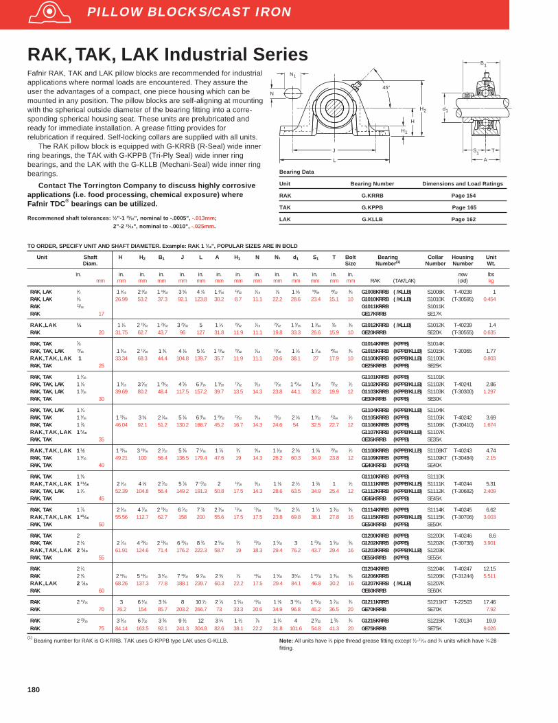
180
RAK, TAK, LAK Industrial SeriesFafnir RAK, TAK and LAK pillow blocks are recommended for industrialapplications where normal loads are encountered. They assure theuser the advantages of a compact, one piece housing which can bemounted in any position. The pillow blocks are self-aligning at mountingwith the spherical outside diameter of the bearing fitting into a corre-sponding spherical housing seat. These units are prelubricated andready for immediate installation. A grease fitting provides forrelubrication if required. Self-locking collars are supplied with all units.
The RAK pillow block is equipped with G-KRRB (R-Seal) wide innerring bearings, the TAK with G-KPPB (Tri-Ply Seal) wide inner ringbearings, and the LAK with the G-KLLB (Mechani-Seal) wide inner ringbearings.
Contact The Torrington Company to discuss highly corrosiveapplications (i.e. food processing, chemical exposure) whereFafnir TDC ® bearings can be utilized.
Recommened shaft tolerances: 1⁄2"-1 15⁄16", nominal to -.0005", -.013mm;
2"-2 15⁄16", nominal to -.0010", -.025mm.
Bearing Data
Unit Bearing Number Dimensions and Load Ratings
RAK G.KRRB Page 154
TAK G.KPPB Page 165
LAK G.KLLB Page 162
PILLOW BLOCKS/CAST IRON
S T
A
d
B
1
1
1
H
E
F
J
L
45°N
N
1
H
1
H2
TO ORDER, SPECIFY UNIT AND SHAFT DIAMETER. Example: RAK 1 7⁄16", POPULAR SIZES ARE IN BOLD
Unit Shaft H H 2 B1 J L A H 1 N N1 d1 S1 T Bolt Bearing Collar Housing UnitDiam. Size Number (1) Number Number Wt.
in. in. in. in. in. in. in. in. in. in. in. in. in. in. new lbsmm mm mm mm mm mm mm mm mm mm mm mm mm mm RAK (TAK/LAK) (old) kg
RAK, LAK 1⁄2 1 1⁄16 2 3⁄32 1 15⁄32 3 5⁄8 4 7⁄8 1 3⁄16 11⁄32 7⁄16 7⁄8 1 1⁄8 59⁄64 19⁄32 3⁄8 G1008KRRB ( /KLLB) S1008K T-40238 1RAK, LAK 5⁄8 26.99 53.2 37.3 92.1 123.8 30.2 8.7 11.1 22.2 28.6 23.4 15.1 10 G1010KRRB ( /KLLB) S1010K (T-30595) 0.454RAK 11⁄16 G1011KRRB S1011KRAK 17 GE17KRRB SE17K
RAK,LAK 3⁄4 1 1⁄4 2 15⁄32 1 23⁄32 3 25⁄32 5 1 1⁄4 15⁄32 7⁄16 25⁄32 1 5⁄16 1 3⁄64 5⁄8 3⁄8 G1012KRRB ( /KLLB) S1012K T-40239 1.4RAK 20 31.75 62.7 43.7 96 127 31.8 11.9 11.1 19.8 33.3 26.6 15.9 10 GE20KRRB SE20K (T-30555) 0.635
RAK, TAK 7⁄8 G1014KRRB (KPPB) S1014KRAK, TAK, LAK 15⁄16 1 5⁄16 2 11⁄16 1 3⁄4 4 1⁄8 5 1⁄2 1 13⁄32 15⁄32 7⁄16 13⁄16 1 1⁄2 1 1⁄16 45⁄64 3⁄8 G1015KRRB (KPPB/KLLB) S1015K T-30365 1.77RAK,TAK,LAK 1 33.34 68.3 44.4 104.8 139.7 35.7 11.9 11.1 20.6 38.1 27 17.9 10 G1100KRRB (KPPB/KLLB) S1100K 0.803RAK, TAK 25 GE25KRRB (KPPB) SE25K
RAK, TAK 1 1⁄16 G1101KRRB (KPPB) S1101KRAK, TAK, LAK 1 1⁄8 1 9⁄16 3 5⁄32 1 29⁄32 4 5⁄8 6 3⁄16 1 9⁄16
17⁄329⁄16
15⁄16 1 47⁄64 1 3⁄1625⁄32
1⁄2 G1102KRRB (KPPB/KLLB) S1102K T-40241 2.86RAK, TAK, LAK 1 3⁄16 39.69 80.2 48.4 117.5 157.2 39.7 13.5 14.3 23.8 44.1 30.2 19.9 12 G1103KRRB (KPPB/KLLB) S1103K (T-30300) 1.297RAK, TAK 30 GE30KRRB (KPPB) SE30K
RAK, TAK, LAK 1 1⁄4 G1104KRRB (KPPB/KLLB) S1104KRAK, TAK 1 5⁄16 1 13⁄16 3 5⁄8 2 1⁄64 5 1⁄8 6 9⁄16 1 25⁄32
21⁄329⁄16
31⁄32 2 1⁄8 1 9⁄3257⁄64
1⁄2 G1105KRRB (KPPB) S1105K T-40242 3.69RAK, TAK 1 3⁄8 46.04 92.1 51.2 130.2 166.7 45.2 16.7 14.3 24.6 54 32.5 22.7 12 G1106KRRB (KPPB) S1106K (T-30410) 1.674RAK,TAK,LAK 17⁄16 G1107KRRB (KPPB/KLLB) S1107KRAK, TAK 35 GE35KRRB (KPPB) SE35K
RAK,TAK,LAK 11⁄2 1 15⁄16 3 15⁄16 2 7⁄32 5 3⁄8 7 1⁄16 1 7⁄8 3⁄4 9⁄16 1 1⁄32 2 3⁄8 1 3⁄8 15⁄16 1⁄2 G1108KRRB (KPPB/KLLB) S1108KT T-40243 4.74RAK, TAK 1 9⁄16 49.21 100 56.4 136.5 179.4 47.6 19 14.3 26.2 60.3 34.9 23.8 12 G1109KRRB (KPPB) S1109KT (T-30484) 2.15RAK, TAK 40 GE40KRRB (KPPB) SE40K
RAK, TAK 1 5⁄8 G1110KRRB (KPPB) S1110KRAK,TAK,LAK 111⁄16 2 1⁄16 4 1⁄8 2 7⁄32 5 7⁄8 7 17⁄32 2 11⁄16 9⁄16 1 1⁄8 2 1⁄2 1 3⁄8 1 1⁄2 G1111KRRB (KPPB/KLLB) S1111K T-40244 5.31RAK, TAK, LAK 1 3⁄4 52.39 104.8 56.4 149.2 191.3 50.8 17.5 14.3 28.6 63.5 34.9 25.4 12 G1112KRRB (KPPB/KLLB) S1112K (T-30682) 2.409RAK, TAK 45 GE45KRRB (KPPB) SE45K
RAK, TAK 1 7⁄8 2 3⁄16 4 7⁄16 2 15⁄32 6 7⁄32 7 7⁄8 2 3⁄1611⁄16
11⁄1615⁄16 2 3⁄4 1 1⁄2 1 3⁄32
5⁄8 G1114KRRB (KPPB) S1114K T-40245 6.62RAK,TAK,LAK 115⁄16 55.56 112.7 62.7 158 200 55.6 17.5 17.5 23.8 69.8 38.1 27.8 16 G1115KRRB (KPPB/KLLB) S1115K (T-30706) 3.003RAK, TAK 50 GE50KRRB (KPPB) SE50K
RAK, TAK 2 G1200KRRB (KPPB) S1200K T-40246 8.6RAK, TAK 2 1⁄8 2 7⁄16 4 29⁄32 2 13⁄16 6 15⁄16 8 3⁄4 2 5⁄16
3⁄4 23⁄32 1 5⁄32 3 1 23⁄32 1 5⁄325⁄8 G1202KRRB (KPPB) S1202K (T-30738) 3.901
RAK,TAK,LAK 2 3⁄16 61.91 124.6 71.4 176.2 222.3 58.7 19 18.3 29.4 76.2 43.7 29.4 16 G1203KRRB (KPPB/KLLB) S1203KRAK, TAK 55 GE55KRRB (KPPB) SE55K
RAK 2 1⁄4 G1204KRRB S1204K T-40247 12.15RAK 2 3⁄8 2 11⁄16 5 13⁄32 3 1⁄16 7 13⁄32 9 7⁄16 2 3⁄8 7⁄8 11⁄16 1 5⁄32 3 5⁄16 1 27⁄32 1 3⁄16 5⁄8 G1206KRRB S1206K (T-31244) 5.511RAK,LAK 2 7⁄16 68.26 137.3 77.8 188.1 239.7 60.3 22.2 17.5 29.4 84.1 46.8 30.2 16 G1207KRRB ( /KLLB) S1207KRAK 60 GE60KRRB SE60K
RAK 2 11⁄16 3 6 1⁄16 3 3⁄8 8 10 1⁄2 2 7⁄8 1 5⁄16 13⁄16 1 3⁄8 3 13⁄16 1 25⁄32 1 7⁄16 3⁄4 G1211KRRB S1211KT T-22503 17.46RAK 70 76.2 154 85.7 203.2 266.7 73 33.3 20.6 34.9 96.8 45.2 36.5 20 GE70KRRB SE70K 7.92
RAK 2 15⁄16 3 5⁄16 6 7⁄16 3 5⁄8 9 1⁄2 12 3 1⁄4 1 1⁄2 7⁄8 1 1⁄4 4 2 5⁄32 1 5⁄8 3⁄4 G1215KRRB S1215K T-20134 19.9RAK 75 84.14 163.5 92.1 241.3 304.8 82.6 38.1 22.2 31.8 101.6 54.8 41.3 20 GE75KRRB SE75K 9.026
(1) Bearing number for RAK is G-KRRB. TAK uses G-KPPB type LAK uses G-KLLB. Note: All units have 1⁄8 pipe thread grease fitting except 1⁄2-11⁄16 and 3⁄4 units which have 1⁄4-28
fitting.
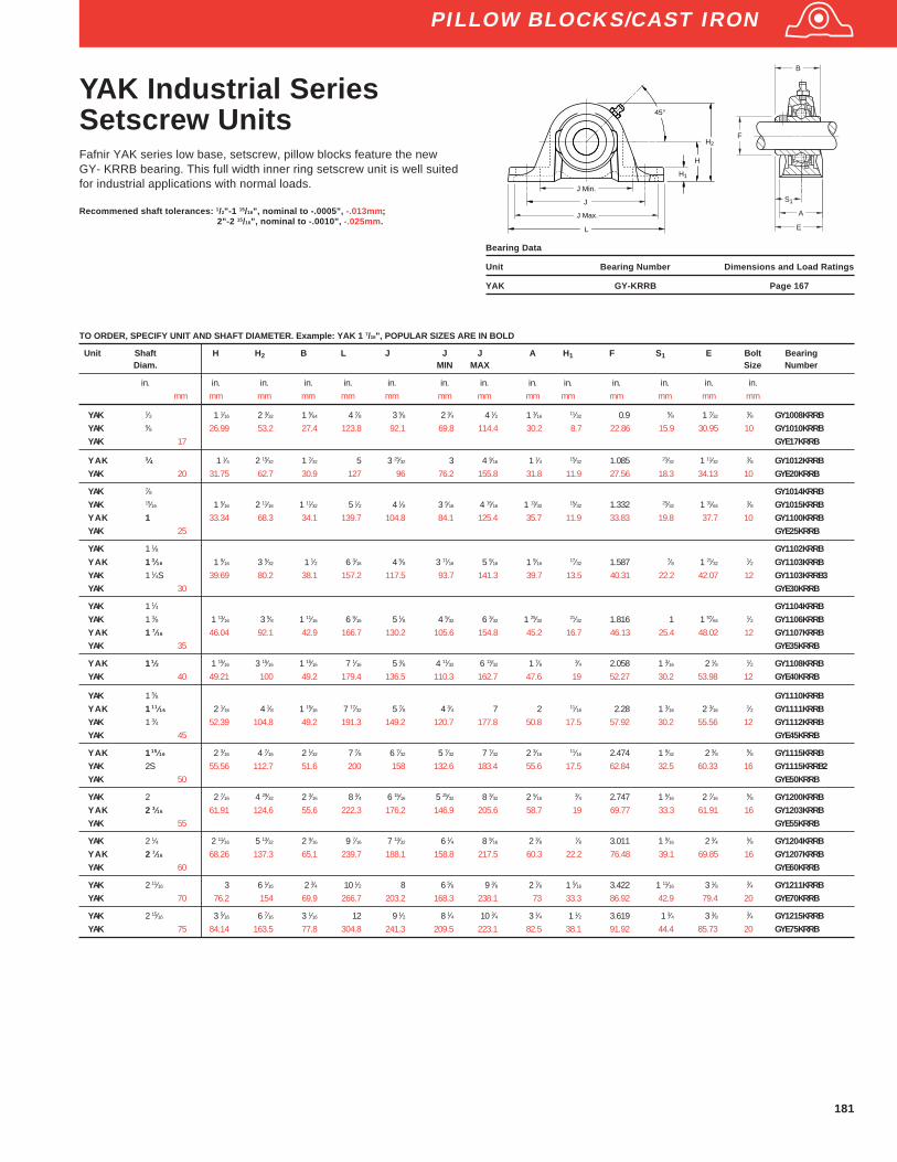
181
YAK Industrial SeriesSetscrew UnitsFafnir YAK series low base, setscrew, pillow blocks feature the newGY- KRRB bearing. This full width inner ring setscrew unit is well suitedfor industrial applications with normal loads.
Recommened shaft tolerances: 1/2"-1 15/16", nominal to -.0005", -.013mm;2"-2 15/16", nominal to -.0010", -.025mm.
TO ORDER, SPECIFY UNIT AND SHAFT DIAMETER. Example: YAK 1 7/16", POPULAR SIZES ARE IN BOLD
Unit Shaft H H 2 B L J J J A H 1 F S1 E Bolt BearingDiam. MIN MAX Size Number
in. in. in. in. in. in. in. in. in. in. in. in. in. in.mm mm mm mm mm mm mm mm mm mm mm mm mm mm
YAK 1⁄2 1 1⁄16 2 3⁄32 1 5⁄64 4 7⁄8 3 5⁄8 2 3⁄4 4 1⁄2 1 3⁄16 11⁄32 0.9 5⁄8 1 7⁄32 3⁄8 GY1008KRRBYAK 5⁄8 26.99 53.2 27.4 123.8 92.1 69.8 114.4 30.2 8.7 22.86 15.9 30.95 10 GY1010KRRBYAK 17 GYE17KRRB
YAK 3⁄4 1 1⁄4 2 15⁄32 1 7⁄32 5 3 25⁄32 3 4 9⁄16 1 1⁄4 15⁄32 1.085 23⁄32 1 11⁄32 3⁄8 GY1012KRRBYAK 20 31.75 62.7 30.9 127 96 76.2 155.8 31.8 11.9 27.56 18.3 34.13 10 GYE20KRRB
YAK 7⁄8 GY1014KRRBYAK 15⁄16 1 5⁄16 2 11⁄16 1 11⁄32 5 1⁄2 4 1⁄8 3 5⁄16 4 15⁄16 1 13⁄32 15⁄32 1.332 25⁄32 1 31⁄64 3⁄8 GY1015KRRBYAK 1 33.34 68.3 34.1 139.7 104.8 84.1 125.4 35.7 11.9 33.83 19.8 37.7 10 GY1100KRRBYAK 25 GYE25KRRB
YAK 1 1⁄8 GY1102KRRBYAK 13⁄16 1 9⁄16 3 5⁄32 1 1⁄2 6 3⁄16 4 5⁄8 3 11⁄16 5 9⁄16 1 9⁄16
17⁄32 1.587 7⁄8 1 21⁄321⁄2 GY1103KRRB
YAK 1 1⁄4S 39.69 80.2 38.1 157.2 117.5 93.7 141.3 39.7 13.5 40.31 22.2 42.07 12 GY1103KRRB3YAK 30 GYE30KRRB
YAK 1 1⁄4 GY1104KRRBYAK 1 3⁄8 1 13⁄16 3 5⁄8 1 11⁄16 6 9⁄16 5 1⁄8 4 5⁄32 6 3⁄32 1 25⁄32
21⁄32 1.816 1 1 57⁄641⁄2 GY1106KRRB
YAK 1 7⁄16 46.04 92.1 42.9 166.7 130.2 105.6 154.8 45.2 16.7 46.13 25.4 48.02 12 GY1107KRRBYAK 35 GYE35KRRB
YAK 11⁄2 1 15⁄16 3 15⁄16 1 15⁄16 7 1⁄16 5 3⁄8 4 11⁄32 6 13⁄32 1 7⁄8 3⁄4 2.058 1 3⁄16 2 1⁄8 1⁄2 GY1108KRRBYAK 40 49.21 100 49.2 179.4 136.5 110.3 162.7 47.6 19 52.27 30.2 53.98 12 GYE40KRRB
YAK 1 5⁄8 GY1110KRRBYAK 111⁄16 2 1⁄16 4 1⁄8 1 15⁄16 7 17⁄32 5 7⁄8 4 3⁄4 7 2 11⁄16 2.28 1 3⁄16 2 3⁄16
1⁄2 GY1111KRRBYAK 1 3⁄4 52.39 104.8 49.2 191.3 149.2 120.7 177.8 50.8 17.5 57.92 30.2 55.56 12 GY1112KRRBYAK 45 GYE45KRRB
YAK 115⁄16 2 3⁄16 4 7⁄16 2 1⁄32 7 7⁄8 6 7⁄32 5 7⁄32 7 7⁄32 2 3⁄1611⁄16 2.474 1 9⁄32 2 3⁄8 5⁄8 GY1115KRRB
YAK 2S 55.56 112.7 51.6 200 158 132.6 183.4 55.6 17.5 62.84 32.5 60.33 16 GY1115KRRB2YAK 50 GYE50KRRB
YAK 2 2 7⁄16 4 29⁄32 2 3⁄16 8 3⁄4 6 15⁄16 5 25⁄32 8 3⁄32 2 5⁄163⁄4 2.747 1 5⁄16 2 7⁄16
5⁄8 GY1200KRRBYAK 2 3⁄16 61.91 124.6 55.6 222.3 176.2 146.9 205.6 58.7 19 69.77 33.3 61.91 16 GY1203KRRBYAK 55 GYE55KRRB
YAK 2 1⁄4 2 11⁄16 5 13⁄32 2 9⁄16 9 7⁄16 7 13⁄32 6 1⁄4 8 9⁄16 2 3⁄8 7⁄8 3.011 1 9⁄16 2 3⁄4 5⁄8 GY1204KRRBYAK 2 7⁄16 68.26 137.3 65.1 239.7 188.1 158.8 217.5 60.3 22.2 76.48 39.1 69.85 16 GY1207KRRBYAK 60 GYE60KRRB
YAK 2 11⁄16 3 6 1⁄16 2 3⁄4 10 1⁄2 8 6 5⁄8 9 3⁄8 2 7⁄8 1 5⁄16 3.422 1 11⁄16 3 1⁄8 3⁄4 GY1211KRRBYAK 70 76.2 154 69.9 266.7 203.2 168.3 238.1 73 33.3 86.92 42.9 79.4 20 GYE70KRRB
YAK 2 15⁄16 3 5⁄16 6 7⁄16 3 1⁄16 12 9 1⁄2 8 1⁄4 10 3⁄4 3 1⁄4 1 1⁄2 3.619 1 3⁄4 3 3⁄8 3⁄4 GY1215KRRBYAK 75 84.14 163.5 77.8 304.8 241.3 209.5 223.1 82.5 38.1 91.92 44.4 85.73 20 GYE75KRRB
Bearing Data
Unit Bearing Number Dimensions and Load Ratings
YAK GY-KRRB Page 167
PILLOW BLOCKS/CAST IRON
F
B
A
S1
E
H1
45°
H
H2
J
L
J Min.
J Max.
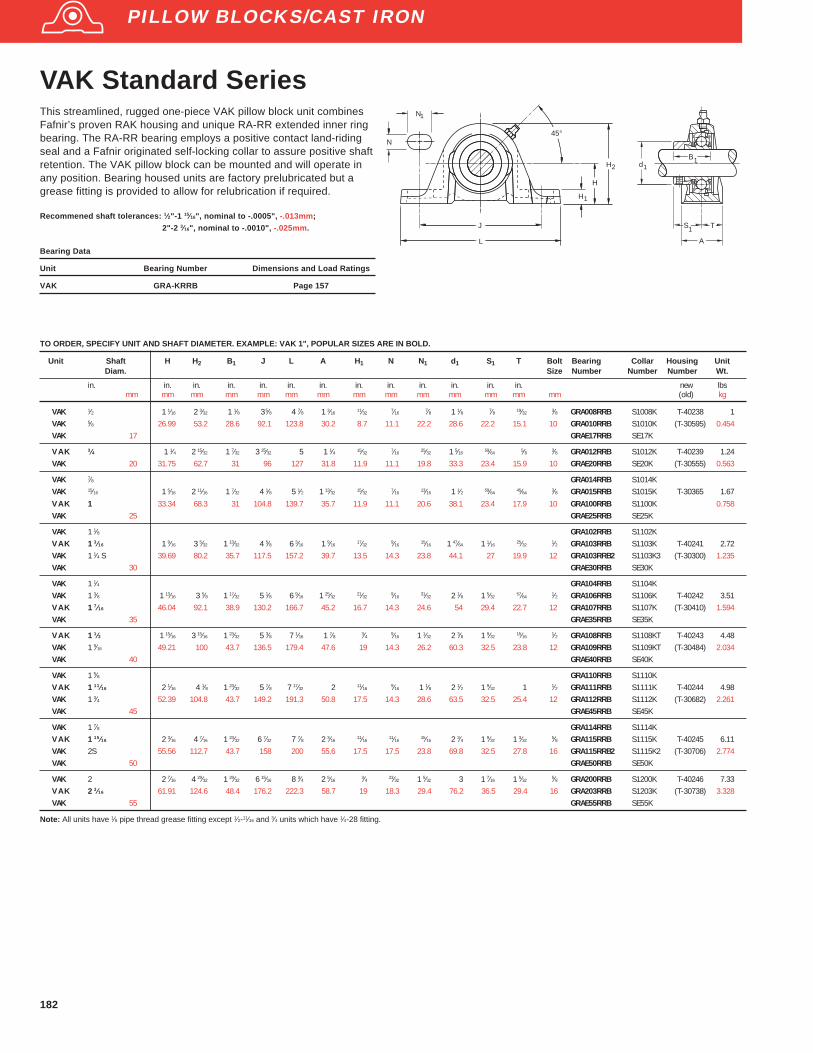
182
VAK Standard SeriesThis streamlined, rugged one-piece VAK pillow block unit combinesFafnir’s proven RAK housing and unique RA-RR extended inner ringbearing. The RA-RR bearing employs a positive contact land-ridingseal and a Fafnir originated self-locking collar to assure positive shaftretention. The VAK pillow block can be mounted and will operate inany position. Bearing housed units are factory prelubricated but agrease fitting is provided to allow for relubrication if required.
Recommened shaft tolerances: 1⁄2"-1 15⁄16", nominal to -.0005", -.013mm;
2"-2 3⁄16", nominal to -.0010", -.025mm.
H
E
F
H
J
L
45°N
N
1
H
1
2
S T
A
dB
11
1
Bearing Data
Unit Bearing Number Dimensions and Load Ratings
VAK GRA-KRRB Page 157
TO ORDER, SPECIFY UNIT AND SHAFT DIAMETER. EXAMPLE: VAK 1", POPULAR SIZES ARE IN BOLD.
Unit Shaft H H 2 B1 J L A H 1 N N1 d1 S1 T Bolt Bearing Collar Housing UnitDiam. Size Number Number Number Wt.
in. in. in. in. in. in. in. in. in. in. in. in. in. new lbsmm mm mm mm mm mm mm mm mm mm mm mm mm mm (old) kg
VAK 1⁄2 1 1⁄16 2 3⁄32 1 1⁄8 3 5⁄8 4 7⁄8 1 3⁄16 11⁄32 7⁄16 7⁄8 1 1⁄8 7⁄8 19⁄32 3⁄8 GRA008RRB S1008K T-40238 1VAK 5⁄8 26.99 53.2 28.6 92.1 123.8 30.2 8.7 11.1 22.2 28.6 22.2 15.1 10 GRA010RRB S1010K (T-30595) 0.454VAK 17 GRAE17RRB SE17K
VAK 3⁄4 1 1⁄4 2 15⁄32 1 7⁄32 3 25⁄32 5 1 1⁄4 15⁄32 7⁄16 25⁄32 1 5⁄16 59⁄64 5⁄8 3⁄8 GRA012RRB S1012K T-40239 1.24VAK 20 31.75 62.7 31 96 127 31.8 11.9 11.1 19.8 33.3 23.4 15.9 10 GRAE20RRB SE20K (T-30555) 0.563
VAK 7⁄8 GRA014RRB S1014KVAK 15⁄16 1 5⁄16 2 11⁄16 1 7⁄32 4 1⁄8 5 1⁄2 1 13⁄32 15⁄32 7⁄16 13⁄16 1 1⁄2 59⁄64 45⁄64 3⁄8 GRA015RRB S1015K T-30365 1.67VAK 1 33.34 68.3 31 104.8 139.7 35.7 11.9 11.1 20.6 38.1 23.4 17.9 10 GRA100RRB S1100K 0.758VAK 25 GRAE25RRB SE25K
VAK 1 1⁄8 GRA102RRB S1102KVAK 13⁄16 1 9⁄16 3 5⁄32 1 13⁄32 4 5⁄8 6 3⁄16 1 9⁄16
17⁄329⁄16
15⁄16 1 47⁄64 1 1⁄1625⁄32
1⁄2 GRA103RRB S1103K T-40241 2.72VAK 1 1⁄4 S 39.69 80.2 35.7 117.5 157.2 39.7 13.5 14.3 23.8 44.1 27 19.9 12 GRA103RRB2 S1103K3 (T-30300) 1.235VAK 30 GRAE30RRB SE30K
VAK 1 1⁄4 GRA104RRB S1104KVAK 1 3⁄8 1 13⁄16 3 5⁄8 1 17⁄32 5 1⁄8 6 9⁄16 1 25⁄32
21⁄329⁄16
31⁄32 2 1⁄8 1 5⁄3257⁄64
1⁄2 GRA106RRB S1106K T-40242 3.51VAK 17⁄16 46.04 92.1 38.9 130.2 166.7 45.2 16.7 14.3 24.6 54 29.4 22.7 12 GRA107RRB S1107K (T-30410) 1.594VAK 35 GRAE35RRB SE35K
VAK 11⁄2 1 15⁄16 3 15⁄16 1 23⁄32 5 3⁄8 7 1⁄16 1 7⁄8 3⁄4 9⁄16 1 1⁄32 2 3⁄8 1 9⁄3215⁄16
1⁄2 GRA108RRB S1108KT T-40243 4.48VAK 1 9⁄16 49.21 100 43.7 136.5 179.4 47.6 19 14.3 26.2 60.3 32.5 23.8 12 GRA109RRB S1109KT (T-30484) 2.034VAK 40 GRAE40RRB SE40K
VAK 1 5⁄8 GRA110RRB S1110KVAK 111⁄16 2 1⁄16 4 1⁄8 1 23⁄32 5 7⁄8 7 17⁄32 2 11⁄16
9⁄16 1 1⁄8 2 1⁄2 1 9⁄32 1 1⁄2 GRA111RRB S1111K T-40244 4.98VAK 1 3⁄4 52.39 104.8 43.7 149.2 191.3 50.8 17.5 14.3 28.6 63.5 32.5 25.4 12 GRA112RRB S1112K (T-30682) 2.261VAK 45 GRAE45RRB SE45K
VAK 1 7⁄8 GRA114RRB S1114KVAK 115⁄16 2 3⁄16 4 7⁄16 1 23⁄32 6 7⁄32 7 7⁄8 2 3⁄16
11⁄1611⁄16
15⁄16 2 3⁄4 1 9⁄32 1 3⁄325⁄8 GRA115RRB S1115K T-40245 6.11
VAK 2S 55.56 112.7 43.7 158 200 55.6 17.5 17.5 23.8 69.8 32.5 27.8 16 GRA115RRB2 S1115K2 (T-30706) 2.774VAK 50 GRAE50RRB SE50K
VAK 2 2 7⁄16 4 29⁄32 1 29⁄32 6 15⁄16 8 3⁄4 2 5⁄163⁄4 23⁄32 1 5⁄32 3 1 7⁄16 1 5⁄32
5⁄8 GRA200RRB S1200K T-40246 7.33VAK 23⁄16 61.91 124.6 48.4 176.2 222.3 58.7 19 18.3 29.4 76.2 36.5 29.4 16 GRA203RRB S1203K (T-30738) 3.328VAK 55 GRAE55RRB SE55K
Note: All units have 1⁄8 pipe thread grease fitting except 1⁄2-11⁄16 and 3⁄4 units which have 1⁄4-28 fitting.
PILLOW BLOCKS/CAST IRON

183
RAS,TAS, LASIndustrial SeriesFafnir RAS, TAS and LAS pillow blocks are similar in design and equalin load carrying capacity to the RAK, TAK and LAK types but have aslightly higher base to center height dimension to make them inter-changeable with certain other competitive designs.
The RAS pillow block is equipped with G-KRRB (R-Seal) wide innerring bearings, the TAS with G-KPPB (Tri-Ply Seal) wide inner ringbearings, and the LAS with the G-KLLB (Mechani-Seal) wide inner ringbearings.
Contact The Torrington Company to discuss highly corrosiveapplications (i.e. food processing, chemical exposure) whereFafnir TDC ® bearings can be utilized.
Recommened shaft tolerances: 1/2"-1 15/16", nominal to -.0005", -.013mm;2"-2 3/16", nominal to -.0010", -.025mm.
TO ORDER, SPECIFY UNIT AND SHAFT DIAMETER. Example: RAS 1 3/16", POPULAR SIZES ARE IN BOLD
Unit Shaft H H 2 B1 J L A H 1 N N1 d1 S1 T Bolt Bearing Collar Housing UnitDiam. Size Number (1) Number Number Wt.
in. in. in. in. in. in. in. in. in. in. in. in. in. in. new lbsmm mm mm mm mm mm mm mm mm mm mm mm mm mm RAS (TAS) (old) kg
RAS 1⁄2 G1008KRRB S1008KRAS 5⁄8 1 3⁄16 2 7⁄32 1 15⁄32 3 5⁄8 4 7⁄8 1 3⁄16 15⁄32 7⁄16 7⁄8 1 1⁄8 59⁄64 19⁄32 3⁄8 G1010KRRB S1010K T-40238 1.00RAS 11⁄16 30.16 56.4 37.3 92.1 123.8 30.2 11.9 11.1 22.2 28.6 23.4 15.1 10 G1011KRRB S1011K (T-30595) 0.454RAS 17 GE17KRRB SE17K
RAS 3⁄4 1 5⁄16 2 17⁄32 1 23⁄32 3 25⁄32 5 1 1⁄4 17⁄32 7⁄16 25⁄32 1 5⁄16 1 3⁄64 5⁄8 3⁄8 G1012KRRB S1012K T-40239 1.40RAS 20 33.34 64.3 43.7 96 127 31.8 13.5 11.1 19.8 33.3 26.6 15.9 10 GE20KRRB SE20K (T-30555) 0.635
RAS,TAS 7⁄8 G1014KRRB (KPPB) S1014KRAS,TAS 15⁄16 1 7⁄16 2 13⁄16 1 3⁄4 4 1⁄8 5 1⁄2 1 13⁄32
19⁄327⁄16
13⁄16 1 1⁄2 1 1⁄1645⁄64
3⁄8 G1015KRRB (KPPB) S1015K 1.77RAS,TAS,LAS 1 36.51 71.4 44.4 104.8 139.7 35.7 15.1 11.1 20.6 38.1 27 17.9 10 G1100KRRB (KPPB) S1100K T-30365 0.803RAS,TAS 25 GE25KRRB (KPPB) SE25K
RAS,TAS 1 1⁄16 G1101KRRB (KPPB) S1101KRAS,TAS 1 1⁄8 1 11⁄16 3 9⁄32 1 29⁄32 4 5⁄8 6 3⁄16 1 9⁄16
21⁄329⁄16
15⁄16 1 3⁄4 1 3⁄1625⁄32
1⁄2 G1102KRRB (KPPB) S1102K T-40241 2.86RAS,TAS,LAS 1 3⁄16 42.86 83.3 48.4 117.5 157.2 39.7 16.7 14.3 23.8 49.5 30.2 19.9 12 G1103KRRB (KPPB) S1103K (T-30300) 1.297RAS,TAS 30 GE30KRRB (KPPB) SE30K
RAS,TAS 1 1⁄4 G1104KRRB (KPPB) S1104KRAS,TAS 1 5⁄16 1 7⁄8 3 11⁄16 2 1⁄64 5 1⁄8 6 9⁄16 1 25⁄32
23⁄329⁄16
31⁄32 2 1⁄8 1 9⁄3257⁄64
1⁄2 G1105KRRB (KPPB) S1105K T-40242 3.69RAS,TAS 1 3⁄8 47.62 93.7 51.2 130.2 166.7 45.2 18.3 14.3 24.6 54 32.5 22.7 12 G1106KRRB (KPPB) S1106K (T-30410) 1.674RAS,TAS,LAS 17⁄16 G1107KRRB (KPPB) S1107KRAS,TAS 35 GE35KRRB (KPPB) SE35K
RAS,TAS 1 1⁄2 1 15⁄16 3 15⁄16 2 7⁄32 5 3⁄8 7 1⁄16 1 7⁄8 3⁄4 9⁄16 1 1⁄32 2 3⁄8 1 3⁄8 15⁄161⁄2 G1108KRRB (KPPB) S1108KT T-40243 4.74
RAS,TAS 1 9⁄16 49.21 100 56.4 136.5 179.4 47.6 19 14.3 26.2 60.3 34.9 23.8 12 G1109KRRB (KPPB) S1109KT (T-30484) 2.150RAS,TAS 40 GE40KRRB (KPPB) SE40K
RAS,TAS 1 5⁄8 G1110KRRB (KPPB) S1110KRAS,TAS 1 11⁄16 2 1⁄8 4 3⁄16 2 7⁄32 5 7⁄8 7 17⁄32 2 3⁄4 9⁄16 1 1⁄8 2 1⁄2 1 3⁄8 1 1⁄2 G1111KRRB (KPPB) S1111K T-40244 5.31RAS,TAS 1 3⁄4 53.98 106.4 56.4 149.2 191.3 50.8 19 14.3 28.6 63.5 34.9 25.4 12 G1112KRRB (KPPB) S1112K (T-30682) 2.409RAS,TAS 45 GE45KRRB (KPPB) SE45K
RAS,TAS 1 7⁄8 2 1⁄4 4 1⁄2 2 15⁄16 6 7⁄32 7 7⁄8 2 3⁄163⁄4 11⁄16
15⁄16 2 3⁄4 1 1⁄2 1 3⁄325⁄8 G1114KRRB (KPPB) S1114K T-40245 6.62
RAS,TAS,LAS 1 15⁄16 57.15 114.3 62.7 158 200 55.6 19 17.5 23.8 69.8 38.1 27.8 16 G1115KRRB (KPPB) S1115K (T-30706) 3.003RAS,TAS 50 GE50KRRB (KPPB) SE50K
RAS,TAS 2 G1200KRRB (KPPB) S1200KRAS,TAS 2 1⁄8 2 1⁄2 4 31⁄32 2 13⁄16 6 15⁄16 8 3⁄4 2 5⁄16
13⁄1623⁄32 1 5⁄32 3 1 23⁄32 1 5⁄32
5⁄8 G1202KRRB (KPPB) S1202K T-40246 8.60RAS,TAS 2 3⁄16 63.5 126.2 71.4 176.2 222.3 58.7 20.6 18.3 29.4 76.2 43.7 29.4 16 G1203KRRB (KPPB) S1203K (T-30738) 3.901RAS,TAS 55 GE55KRRB (KPPB) SE55K
RAS 2 1⁄4 2 3⁄4 5 15⁄32 3 1⁄16 7 13⁄32 9 7⁄16 2 3⁄8 15⁄1623⁄32 1 5⁄32 3 5⁄16 1 27⁄32 1 3⁄16
5⁄8 G1204KRRB S1204K T-40247 12.15RAS 2 3⁄8 69.85 138.9 77.8 188.1 239.7 60.3 23.8 18.3 29.4 84.1 46.8 30.2 16 G1206KRRB S1206K (T-31244) 5.511RAS,LAS 2 7⁄16 G1207KRRB S1207KRAS 60 GE60KRRB SE60K
RAS 2 15⁄16 3 1⁄4 6 15⁄32 3 5⁄8 8 1⁄2 10 5⁄8 2 3⁄4 1 7⁄8 1 1⁄4 4 2 5⁄32 1 3⁄8 3⁄4 G1215KRRB S1215K T-23423 19.90RAS 75 82.55 164.3 92.1 215.9 269.9 69.9 25.4 22.2 31.8 101.6 54.8 34.9 20 GE75KRRB SE75K 9.026(1)
Bearing number for RAS is G-KRRB. TAS uses G-KPPB, type LAS uses G-KLLB. Note: All units have 1/8 pipe thread grease fitting except 1/2-11/16 and 3/4 units which have 1/4-28 fitting.
H
H
E
F
J
L
45°N
N
1
H
1
2
S T
A
d
B
1
1
1
Bearing Data
Unit Bearing Number Dimensions and Load Ratings
RAS G-KRRB Page 154
TAS G-KPPB Page 165
LAS G-KLLB Page 162
PILLOW BLOCKS/CAST IRON

184
RASC Industrial SeriesConcentric CollarAll RASC pillow blocks are equipped with GC-KRRB (R-Seal) wideinner ring bearings with concentric collars.The pillow blocks are self-aligning at mounting with the spherical outside diameter of the bearingfitting into a corresponding spherical housing seat. These units areprelubricated and ready for immediate installation. A grease fittingprovides for relubrication if required. Concentric collars are suppliedwith all units.
Recommened shaft tolerances: 1/2"-1 15/16", nominal to -.0005", -.013mm;
2"-2 15/16", nominal to -.0010", -.025mm.
TO ORDER, SPECIFY UNIT AND SHAFT DIAMETER. Example: RASC 1"
Unit Shaft H H 2 B1 J L A H 1 N N1 d1 S1 T G Bolt Bearing Collar Housing UnitDiam. Size Number Number Number Wt.
in. in. in. in. in. in. in. in. in. in. in. in. in. in. in. new lbsmm mm mm mm mm mm mm mm mm mm mm mm mm mm mm (old) kg
RASC 5⁄8 1 3⁄16 2 7⁄32 1 3⁄64 3 5⁄8 4 7⁄8 1 3⁄1615⁄32
7⁄167⁄8 1 11⁄32
39⁄6439⁄64 1 7⁄32
3⁄8 GC1010KRRB C203 T-40238 130.16 56.4 26.6 92.1 123.8 30.2 11.9 11.1 22.2 34.1 15.5 15.5 31 10 (T-30595) 0.454
RASC 3⁄4 1 5⁄16 2 17⁄32 1 7⁄32 3 25⁄32 5 1 1⁄4 17⁄327⁄16
25⁄32 1 1⁄2 47⁄6443⁄64 1 13⁄32
3⁄8 GC1012KRRB C204 T-40239 1.4033.34 64.3 31 96 127 31.8 13.5 11.1 19.8 38.1 18.7 17.1 35.7 10 (T-30555) 0.635
RASC 1 1 7⁄16 2 13⁄16 1 11⁄32 4 1⁄8 5 1⁄2 1 13⁄3219⁄32
7⁄1613⁄16 1 3⁄4 51⁄64
45⁄64 1 1⁄2 3⁄8 GC1100KRRB 1.7736.51 71.4 34.1 104.8 139.7 35.7 15.1 11.1 20.2 44.4 20.2 17.9 38.1 10 C205 T-30365 0.803
RASC 1 1⁄8 1 11⁄16 3 9⁄32 1 15⁄32 4 5⁄8 6 3⁄16 1 9⁄1621⁄32
9⁄1615⁄16 2 1⁄16
57⁄647⁄8 1 49⁄64
1⁄2 GC1102KRRBRASC 1 3⁄16 42.86 83.3 37.3 117.5 157.2 39.7 16.7 14.3 23.8 52.4 22.6 22.2 44.8 12 GC1103KRRB C206 T-40241 2.86RASC 1 1⁄4S GC1103KRRB3 (T-30300) 1.297
RASC 1 1⁄4 1 7⁄8 3 11⁄16 1 5⁄8 5 1⁄8 6 9⁄16 1 25⁄32 23⁄32 9⁄16 31⁄32 2 11⁄32 1 7⁄8 1 15⁄16 1⁄2 GC1104KRRB C207 T-40242 3.69RASC 1 3⁄8 47.62 93.7 41.3 130.2 166.7 45.2 18.3 14.3 24.6 59.5 25.4 22.2 49.2 12 GC1106KRRB (T-30410) 1.674RASC 1 7⁄16 GC1107KRRB
RASC 1 1⁄2 1 15⁄16 3 15⁄16 1 47⁄64 5 3⁄8 7 1⁄16 1 7⁄8 3⁄4 9⁄16 1 1⁄32 2 11⁄16 1 5⁄64 31⁄32 2 3⁄64 1⁄2 GC1108KRRB C208 T-40243 4.7449.21 100 44.1 136.5 179.4 47.6 19 14.3 26.2 68.3 27.4 24.6 52 12 (T-30484) 2.150
RASC 1 11⁄16 2 1⁄8 4 3⁄16 1 27⁄32 5 7⁄8 7 17⁄32 2 3⁄4 9⁄16 29⁄32 2 7⁄8 1 5⁄32 1 2 5⁄32 1⁄2 GC1111KRRB C209 T-40244 5.31RASC 1 3⁄4 53.98 106.3 46.8 149.2 191.3 50.8 19 14.3 23 73 29.4 25.4 54.8 12 GC1112KRRB (T-30682) 2.409
RASC 1 15⁄16 2 1⁄4 4 1⁄2 1 29⁄32 6 7⁄32 7 7⁄8 2 3⁄16 3⁄4 11⁄16 15⁄16 3 1⁄8 1 3⁄16 1 3⁄32 2 9⁄32 5⁄8 GC1115KRRB C210 T-40245 6.6257.15 114.3 48.4 158 200 55.6 19 17.5 23.8 79.4 30.2 27.8 57.9 16 (T-30706) 3.003
RASC 2 2 1⁄2 4 31⁄32 2 1⁄8 6 15⁄16 8 3⁄4 2 5⁄16 13⁄16 23⁄32 1 5⁄32 3 1⁄2 1 5⁄16 1 5⁄32 2 15⁄32 5⁄8 GC1200KRRB C211 T-40246 8.60RASC 2 3⁄16 63.5 126.2 54 176.2 222.3 58.7 20.6 18.3 29.4 88.9 33.3 29.4 62.7 16 GC1203KRRG (T-30738) 3.901
RASC 2 7⁄16 2 3⁄4 5 15⁄32 2 3⁄8 7 13⁄32 9 7⁄16 2 3⁄8 15⁄16 23⁄32 1 5⁄32 3 3⁄4 1 15⁄32 1 1⁄4 2 23⁄32 5⁄8 GC1207KRRB C212 T 40247 12.1569.85 138.9 60.3 188.1 239.7 60.3 23.8 18.3 29.4 95.2 37.3 31.8 69.1 16 (T 31244) 5.511
RASC 2 15⁄16 3 1⁄4 6 15⁄32 2 25⁄32 8 1⁄2 10 5⁄8 2 3⁄4 1 7⁄8 1 1⁄4 4 1⁄2 1 23⁄32 1 3⁄8 3 3⁄32 3⁄4 GC1215KRRB C215 T 23423 19.9182.55 164.3 70.6 215.9 269.9 69.9 25.4 22.2 31.8 114.3 43.7 34.9 78.6 20 9.06
Note: All units have 1/8 pipe thread grease fitting except RASC 1⁄2-11/16 and 3/4 units which have 1/4-28 fitting.
Bearing Data
Unit Bearing Number Dimensions and Load Ratings
RASC GC-KRRB Page 166
H
E
F
J
L
45°N
N
1
H
1
H2
S T
G
A
d1
B
1
1
PILLOW BLOCKS/CAST IRON

185
YAS Industrial SeriesSetscrew UnitsFafnir YAS series high base, setscrew, pillow blocks feature the newGY- KRRB bearing. This full width inner ring setscrew unit is wellsuited for industrial applications involving wet and dirtyenvironments.The housing is designed for two bolt mounting in anyposition.
Recommened shaft tolerances: 1⁄2"-1 15⁄16", nominal to -.0005", -.013mm;
2"-2 15⁄16", nominal to -.0010", -.025mm.
TO ORDER, SPECIFY UNIT AND SHAFT DIAMETER. Example: YAS 1 7⁄16", POPULAR SIZES IN BOLD.
Unit Shaft H H 2 B L J J Min J Max A H 1 F S1 E Bolt BearingDiam. Size Number
in. in. in. in. in. in. in. in. in. in. in. in. in. in.mm mm mm mm mm mm mm mm mm mm mm mm mm mm
YAS 1⁄2 1 3⁄16 2 7⁄32 1 5⁄64 4 7⁄8 3 5⁄8 2 3⁄4 4 1⁄2 1 3⁄1615⁄32 0.9 5⁄8 1 7⁄32
3⁄8 GY1008KRRBYAS 5⁄8 30.16 56.4 27.4 123.8 92.1 69.8 114.3 30.2 11.9 22.86 15.9 30.95 10 GY1010KRRBYAS 17 GYE17KRRB
YAS 3⁄4 1 5⁄16 2 17⁄32 1 7⁄32 5 3 25⁄32 3 4 9⁄16 1 1⁄4 17⁄32 1.085 23⁄32 1 11⁄323⁄8 GY1012KRRB
YAS 20 33.34 64.3 30.9 127 96 76.2 155.8 31.8 13.5 27.56 18.3 34.13 10 GYE20KRRB
YAS 7⁄8 GY1014KRRBYAS 15⁄16 1 7⁄16 2 13⁄16 1 11⁄32 5 1⁄2 4 1⁄8 3 5⁄16 4 15⁄16 1 13⁄32
19⁄32 1.332 25⁄32 1 31⁄643⁄8 GY1015KRRB
YAS 1 36.51 71.4 34.1 139.7 104.8 84.1 125.4 35.7 15.1 33.83 19.8 37.7 10 GY1100KRRBYAS 25 GYE25KRRB
YAS 1 1⁄8 GY1102KRRBYAS 1 3⁄16 1 11⁄16 3 9⁄32 1 1⁄2 6 3⁄16 4 5⁄8 3 11⁄16 5 9⁄16 1 9⁄16
21⁄32 1.587 7⁄8 1 21⁄321⁄2 GY1103KRRB
YAS 1 1⁄4S 42.86 83.3 38.1 157.2 117.5 93.7 141.3 39.7 16.7 40.31 22.2 42.07 12 GY1103KRRB3YAS 30 GYE30KRRB
YAS 1 1⁄4 GY1104KRRBYAS 1 3⁄8 1 7⁄8 3 11⁄16 1 11⁄16 6 9⁄16 5 1⁄8 4 5⁄32 6 3⁄32 1 25⁄32 23⁄32 1.816 1 1 57⁄64 1⁄2 GY1106KRRBYAS 17⁄16 47.62 93.6 42.9 166.7 130.2 105.6 154.8 45.2 18.3 46.13 25.4 48.02 12 GY1107KRRBYAS 35 GYE35KRRB
YAS 1 1⁄2 1 15⁄16 3 15⁄16 1 15⁄16 7 1⁄16 5 3⁄8 4 11⁄32 6 13⁄32 1 7⁄8 3⁄4 2.058 1 3⁄16 2 1⁄8 1⁄2 GY1108KRRBYAS 40 49.21 100 49.2 179.4 136.5 110.3 162.7 47.6 19.1 52.27 30.2 53.98 12 GYE40KRRB
YAS 1 1⁄2H 2 1⁄8 4 1⁄8 1 15⁄16 7 1⁄16 5 3⁄8 4 11⁄32 6 13⁄32 1 7⁄8 29⁄32 2.058 1 3⁄16 2 1⁄8 1⁄2 GY1108KRRB53.98 104.8 49.2 179.4 136.5 110.3 162.7 47.6 23 52.27 30.2 53.98 12
YAS 1 5⁄8 GY1110KRRBYAS 111⁄16 2 1⁄8 4 3⁄16 1 15⁄16 7 17⁄32 5 7⁄8 4 3⁄4 7 2 3⁄4 2.28 1 3⁄16 2 3⁄16 1⁄2 GY1111KRRBYAS 1 3⁄4 53.98 106.3 49.2 191.3 149.2 120.7 177.8 50.8 19.1 57.92 30.2 55.56 12 GY1112KRRBYAS 45 GYE45KRRB
YAS 1 15⁄16 2 1⁄4 4 1⁄2 2 1⁄32 7 7⁄8 6 7⁄32 5 7⁄32 7 7⁄32 2 3⁄16 3⁄4 2.474 1 9⁄32 2 3⁄8 5⁄8 GY1115KRRBYAS 2S 57.15 114.3 51.6 200 158 132.6 183.4 55.6 19.1 62.84 32.5 60.33 16 GY1115KRRB2YAS 50 GYE50KRRB
YAS 2 2 1⁄2 4 31⁄32 2 3⁄16 8 3⁄4 6 15⁄16 5 25⁄32 8 3⁄32 2 5⁄16 13⁄16 2.747 1 5⁄16 2 7⁄16 5⁄8 GY1200KRRBYAS 23⁄16 63.5 126.2 55.6 222.3 176.2 146.9 205.6 58.7 20.6 69.77 33.3 61.91 16 GY1203KRRBYAS 55 GYE55KRRB
YAS 2 1⁄4 2 3⁄4 5 15⁄32 2 9⁄16 9 7⁄16 7 13⁄32 6 1⁄4 8 9⁄16 2 3⁄8 15⁄16 3.011 1 9⁄16 2 3⁄4 5⁄8 GY1204KRRBYAS 2 7⁄16 69.85 138.9 65.1 239.7 188.1 158.8 217.5 60.3 23.8 76.48 39.1 69.85 16 GY1207KRRBYAS 60 GYE60KRRB
YAS 2 15⁄16 31⁄4 615⁄32 3 1⁄16 10 5⁄8 8 1⁄2 7 1⁄4 9 3⁄4 2 3⁄4 1 3.619 1 3⁄4 3 1⁄8 3⁄4 GY1215KRRBYAS 75 82.55 164.3 77.8 269.9 215.9 184.2 247.7 69.9 25.4 91.92 44.4 79.38 20 GYE75KRRB
YAS 2 15⁄16H 31⁄2 7 3 1⁄16 13 9 7 11 3 1⁄2 1 1⁄4 3.619 1 3⁄4 3 1⁄2 3⁄4 GY1215KRRB88.9 177.8 77.8 330.2 228.6 177.8 279.4 88.9 31.75 91.92 44.4 88.9 20
Bearing Data
Unit Bearing Number Dimensions and Load Ratings
YAS GY-KRRB Page 167
F
B
A
S1
E
PILLOW BLOCKS/CAST IRON
H1
45°
H
H2
J
L
J Min.
J Max.

186
VAS Standard SeriesFafnir VAS pillow blocks are similar in design and features, and equalin load carrying capacity to the VAK series but have a slightly differentbase to center height dimension to make them interchangeable withcertain other competitive designs. As with the VAK series they areprelubricated, with a grease fitting provided for relubrication if required.
TO ORDER, SPECIFY UNIT AND SHAFT DIAMETER. Example: VAS 1 3⁄16", POPULAR SIZES IN BOLD.
Unit Shaft H H 2 B1 J L A H 1 N N1 d1 S1 T Bolt Bearing Collar Housing UnitDiam. Size Number Number Number Wt.
in. in. in. in. in. in. in. in. in. in. in. in. in. in. new lbsmm mm mm mm mm mm mm mm mm mm mm mm mm mm (old) kg
VAS 1⁄2 1 3⁄16 2 7⁄32 1 1⁄8 3 5⁄8 4 7⁄8 1 3⁄1615⁄32
7⁄167⁄8 1 1⁄8 7⁄8 19⁄32
3⁄8 GRA008RRB S1008K T-40238 1VAS 5⁄8 30.16 56.4 28.6 92.1 123.8 30.2 11.9 11.1 22.2 28.6 22.2 15.1 10 GRA010RRB S1010K (T-30595) 0.454VAS 17 GRAE17RRB SE17K
VAS 3⁄4 1 5⁄16 2 17⁄32 1 7⁄32 3 25⁄32 5 1 1⁄4 17⁄327⁄16
25⁄32 1 5⁄1659⁄64
5⁄8 3⁄8 GRA012RRB S1012K T-40239 1.24VAS 20 33.34 64.3 31 96 127 31.8 13.5 11.1 19.8 33.3 23.4 15.9 10 GRAE20RRB SE20K (T-30555) 0.563
VAS 7⁄8 GRA013RRB S1013KVAS 15⁄16 1 7⁄16 2 13⁄16 1 7⁄32 4 1⁄8 5 1⁄2 1 13⁄32
19⁄327⁄16
13⁄16 1 1⁄2 59⁄6445⁄64
3⁄8 GRA015RRB S1015K 1.67VAS 1 36.51 71.4 31 104.8 139.7 35.7 15.1 11.1 20.6 38.1 23.4 17.9 10 GRA100RRB S1100K T-30365 0.758VAS 25 GRAE25RRB SE25K
VAS 1 1⁄8 GRA102RRB S1102KVAS 13⁄16 1 11⁄16 3 9⁄32 1 13⁄32 4 5⁄8 6 3⁄16 1 9⁄16 21⁄32 9⁄16 15⁄16 1 47⁄64 1 1⁄16 25⁄32 1⁄2 GRA103RRB S1103K T-40241 2.72VAS 1 1⁄4S 42.86 83.3 35.7 117.5 157.2 39.7 16.7 14.3 23.8 44.1 27 19.9 12 GRA103RRB2 S1103K3 (T-30300) 1.235VAS 30 GRAE30RRB SE30K
VAS 1 1⁄4 1 7⁄8 3 11⁄16 1 17⁄32 5 1⁄8 6 9⁄16 1 25⁄32 23⁄32 9⁄16 31⁄32 2 1⁄8 1 5⁄32 57⁄64 1⁄2 GRA104RRB S1104KVAS 1 3⁄8 47.62 93.7 38.9 130.2 166.7 45.2 18.3 14.3 24.6 54 29.4 22.7 12 GRA106RRB S1106K T-40242 3.51VAS 17⁄16 GRA107RRB S1107K (T-30410) 1.594VAS 35 GRAE35RRB SE35K
VAS 11⁄2 1 15⁄16 3 15⁄16 1 23⁄32 5 3⁄8 7 1⁄16 1 7⁄8 3⁄4 9⁄16 1 1⁄32 2 3⁄8 1 9⁄32 15⁄16 1⁄2 GRA108RRB S1108KT T-40243 4.48VAS 40 49.21 100.0 43.7 136.5 179.4 47.6 19.0 14.3 26.2 60.3 32.5 23.8 12 GRAE40RRB SE40K (T-30484) 2.034
VAS 1 5⁄8 GRA110RRB S1110KVAS 111⁄16 2 1⁄8 4 3⁄16 1 23⁄32 5 7⁄8 7 17⁄32 2 3⁄4 9⁄16 1 1⁄8 2 1⁄2 1 9⁄32 1 1⁄2 GRA111RRB S1111K T-40244 4.98VAS 1 3⁄4 53.98 106.4 43.7 149.2 191.3 50.8 19.0 14.3 28.6 63.5 32.5 25.4 12 GRA112RRB S1112K (T-30682) 2.261VAS 45 GRAE45RRB SE45K
VAS 1 7⁄8 GRA114RRB S1114KVAS 115⁄16 2 1⁄4 4 1⁄2 1 23⁄32 6 7⁄32 7 7⁄8 2 3⁄16 3⁄4 23⁄32 1 5⁄32 2 3⁄4 1 9⁄32 1 3⁄32 5⁄8 GRA115RRB S1115K T-40245 6.11VAS 2S 57.15 114.3 43.7 158 200 55.6 19.0 18.3 29.4 69.8 32.5 27.8 16 GRA115RRB2 S1115K2 (T-30706) 2.774VAS 50 GRAE50RRB SE50K
VAS 2 2 1⁄2 4 31⁄32 1 29⁄32 6 15⁄16 8 3⁄4 2 5⁄16 13⁄16 23⁄32 1 5⁄32 3 1 7⁄16 1 5⁄32 5⁄8 GRA200RRB S1200K T-40246 7.33VAS 2 3⁄16 63.5 126.2 48.4 176.2 222.3 58.7 20.6 18.3 29.4 76.2 36.5 29.4 16 GRA203RRB S1203K (T-30738) 3.328VAS 55 GRAE55RRB SE55K
Note: All units have 1/8 pipe thread grease fitting except 1/2-11/16 and 3/4 units which have 1/4-28 fitting.
Recommened shaft tolerances: 1/2"-1 15/16", nominal to -.0005", -.013mm;2"-2 3/16", nominal to -.0010", -.025mm.
Bearing Data
Unit Bearing Number Dimensions and Load Ratings
VAS GRA-RRB Page 157
PILLOW BLOCKS/CAST IRON
H
E
F
J
L
45°
1
H
N
N1
H2
S T
A
dB
11
1
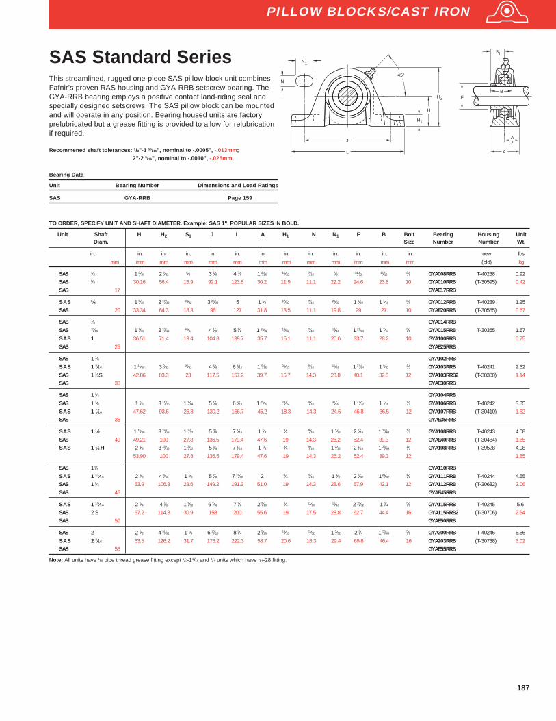
187
SAS Standard SeriesThis streamlined, rugged one-piece SAS pillow block unit combinesFafnir’s proven RAS housing and GYA-RRB setscrew bearing. TheGYA-RRB bearing employs a positive contact land-riding seal andspecially designed setscrews. The SAS pillow block can be mountedand will operate in any position. Bearing housed units are factoryprelubricated but a grease fitting is provided to allow for relubricationif required.
Recommened shaft tolerances: 1/2"-1 15/16", nominal to -.0005", -.013mm;
2"-2 3/16", nominal to -.0010", -.025mm.
Bearing Data
Unit Bearing Number Dimensions and Load Ratings
SAS GYA-RRB Page 159
TO ORDER, SPECIFY UNIT AND SHAFT DIAMETER. Example: SAS 1", POPULAR SIZES IN BOLD.
Unit Shaft H H 2 S1 J L A H 1 N N1 F B Bolt Bearing Housing UnitDiam. Size Number Number Wt.
in. in. in. in. in. in. in. in. in. in. in. in. in. new lbsmm mm mm mm mm mm mm mm mm mm mm mm mm (old) kg
SAS 1⁄2 1 3⁄16 2 7⁄32 5⁄8 3 5⁄8 4 7⁄8 1 3⁄16 15⁄32 7⁄16 7⁄8 31⁄32 15⁄16 3⁄8 GYA008RRB T-40238 0.92SAS 5⁄8 30.16 56.4 15.9 92.1 123.8 30.2 11.9 11.1 22.2 24.6 23.8 10 GYA010RRB (T-30595) 0.42SAS 17 GYAE17RRB
SAS 3⁄4 1 5⁄16 2 17⁄32 23⁄32 3 25⁄32 5 1 1⁄4 17⁄32 7⁄16 25⁄32 1 9⁄64 1 1⁄16 3⁄8 GYA012RRB T-40239 1.25SAS 20 33.34 64.3 18.3 96 127 31.8 13.5 11.1 19.8 29 27 10 GYAE20RRB (T-30555) 0.57
SAS 7⁄8 GYA014RRBSAS 15⁄16 1 7⁄16 2 13⁄16 49⁄64 4 1⁄8 5 1⁄2 1 13⁄32 19⁄32 7⁄16 13⁄16 1 21⁄64 1 7⁄64 3⁄8 GYA015RRB T-30365 1.67SAS 1 36.51 71.4 19.4 104.8 139.7 35.7 15.1 11.1 20.6 33.7 28.2 10 GYA100RRB 0.75SAS 25 GYAE25RRB
SAS 1 1⁄8 GYA102RRBSAS 1 3⁄16 1 11⁄16 3 9⁄32
29⁄32 4 5⁄8 6 3⁄16 1 9⁄1621⁄32
9⁄1615⁄16 1 37⁄64 1 9⁄32
1⁄2 GYA103RRB T-40241 2.52SAS 1 1⁄4S 42.86 83.3 23 117.5 157.2 39.7 16.7 14.3 23.8 40.1 32.5 12 GYA103RRB2 (T-30300) 1.14SAS 30 GYAE30RRB
SAS 1 1⁄4 GYA104RRBSAS 1 3⁄8 1 7⁄8 3 11⁄16 1 1⁄64 5 1⁄8 6 9⁄16 1 25⁄32
23⁄329⁄16
31⁄32 1 27⁄32 1 7⁄161⁄2 GYA106RRB T-40242 3.35
SAS 1 7⁄16 47.62 93.6 25.8 130.2 166.7 45.2 18.3 14.3 24.6 46.8 36.5 12 GYA107RRB (T-30410) 1.52SAS 35 GYAE35RRB
SAS 1 1⁄2 1 15⁄16 3 15⁄16 1 3⁄32 5 3⁄8 7 1⁄16 1 7⁄8 3⁄4 9⁄16 1 1⁄32 2 1⁄16 1 35⁄641⁄2 GYA108RRB T-40243 4.08
SAS 40 49.21 100 27.8 136.5 179.4 47.6 19 14.3 26.2 52.4 39.3 12 GYAE40RRB (T-30484) 1.85SAS 1 1⁄2H 2 1⁄8 3 15⁄16 1 3⁄32 5 3⁄8 7 1⁄16 1 7⁄8 3⁄4 9⁄16 1 1⁄32 2 1⁄16 1 35⁄64
1⁄2 GYA108RRB T-39528 4.0853.90 100 27.8 136.5 179.4 47.6 19 14.3 26.2 52.4 39.3 12 1.85
SAS 1 5⁄8 GYA110RRBSAS 1 11⁄16 2 1⁄8 4 3⁄16 1 1⁄8 5 7⁄8 7 17⁄32 2 3⁄4 9⁄16 1 1⁄8 2 9⁄32 1 21⁄32
1⁄2 GYA111RRB T-40244 4.55SAS 1 3⁄4 53.9 106.3 28.6 149.2 191.3 51.0 19 14.3 28.6 57.9 42.1 12 GYA112RRB (T-30682) 2.06SAS 45 GYAE45RRB
SAS 1 15⁄16 2 1⁄4 4 1⁄2 1 7⁄32 6 7⁄32 7 7⁄8 2 3⁄163⁄4 11⁄16
15⁄16 2 15⁄32 1 3⁄4 5⁄8 GYA115RRB T-40245 5.6SAS 2 S 57.2 114.3 30.9 158 200 55.6 19 17.5 23.8 62.7 44.4 16 GYA115RRB2 (T-30706) 2.54SAS 50 GYAE50RRB
SAS 2 2 1⁄2 4 31⁄32 1 1⁄4 6 15⁄16 8 3⁄4 2 5⁄1613⁄16
23⁄32 1 5⁄32 2 3⁄4 1 53⁄645⁄8 GYA200RRB T-40246 6.66
SAS 2 3⁄16 63.5 126.2 31.7 176.2 222.3 58.7 20.6 18.3 29.4 69.8 46.4 16 GYA203RRB (T-30738) 3.02SAS 55 GYAE55RRB
Note: All units have 1/8 pipe thread grease fitting except 1/2-11/16 and 3/4 units which have 1/4-28 fitting.
H
H
H
J
L
45°N
N
1
1
2
A
F
A2
S 1
B
PILLOW BLOCKS/CAST IRON

188
RAKH Industrial SeriesFafnir RAKH pillow blocks are similar in design to other series pillow blocks buthave slightly different dimensions to allow interchangeability with certaincompetitive designs. They may be used independently or in conjunction withRAKHL expansion units shown below. Used in this capacity, the RAKH pillowblocks provide fixed shaft location while the RAKHL and expansion unitsallows for axial movement.
The maximum operating temperature for the RAKH units is 250° F (121°C).Units are supplied with self-locking collars.
Recommended shaft tolerances: 13⁄16"-1 15⁄16", nominal to -.0005", -.013mm;2"-2 15⁄16", nominal to -.0010", -.025mm.
FAFNIR
H
H
J
45°N
N
L
1
1
H
2
A
d
B
1
1
A2
S1
TO ORDER, SPECIFY UNIT AND SHAFT DIAMETER. Example: RAKH 1 7⁄16"(1)
Unit(2)
Shaft H H 2 B1 J L A H 1 N N1 d1 S1 Bolt Bearing Collar Housing UnitDiam. Size Number Number Number Wt.
in. in. in. in. in. in. in. in. in. in. in. in. in. new lbsmm mm mm mm mm mm mm mm mm mm mm mm mm (old) kg
RAKH 1 1 3⁄4 3 1⁄4 1 3⁄4 4 11⁄16 6 1⁄4 2 5⁄8 9⁄16 1 1 1⁄2 1 1⁄16 3⁄8 G1100KRRB S1100K T-22295 3.7244.45 82.6 44.4 119.1 158.8 50.8 15.9 14.3 25.4 38.1 27 9.5 1.689
RAKH 1 3⁄16 1 7⁄8 3 9⁄16 1 29⁄32 5 6 7⁄8 2 1⁄4 11⁄169⁄16 1 1 47⁄64 1 3⁄16
1⁄2 G1103KRRB S1103K T-22216 4.8147.63 90.5 48.4 127 174.6 57.2 17.5 14.3 25.4 44.1 30.2 12.7 2.184
RAKH 1 1⁄4 2 1⁄8 4 2 1⁄64 5 11⁄16 8 2 1⁄4 3⁄4 9⁄16 1 3⁄16 2 1⁄8 1 9⁄321⁄2 G1104KRRB S1104K T-22212 6.42
RAKH 1 7⁄16 53.98 101.6 51.2 144.5 203.2 57.2 19 14.3 30.2 54 32.5 12.7 G1107KRRB S1107K 2.915
RAKH 1 1⁄2 2 5⁄16 4 3⁄8 2 7⁄32 6 1⁄8 8 3⁄4 2 5⁄8 13⁄16 11⁄16 1 1⁄4 2 3⁄8 1 3⁄8 1⁄2 G1108KRRB S1108KT 8.8258.74 111.1 56.4 155.6 222.2 66.7 20.6 17.5 31.8 60.3 34.9 12.7 T-22291 4.004
RAKH 1 11⁄16 2 5⁄16 4 1⁄2 2 7⁄32 6 1⁄8 8 3⁄4 2 5⁄8 13⁄16 11⁄16 1 5⁄16 2 1⁄2 1 3⁄8 1⁄2 G1111KRRB S1111K T-22293 8.88RAKH 1 3⁄4 58.74 114.3 56.4 155.6 222.2 66.7 20.6 17.5 33.3 63.5 34.9 12.7 G1112KRRB S1112K 4.032
RAKH 1 15⁄16 2 1⁄2 4 13⁄16 2 15⁄32 6 3⁄4 9 1⁄2 2 7⁄8 7⁄8 11⁄16 1 7⁄16 2 3⁄4 1 1⁄2 1⁄2 G1115KRRB S1115K T-22214 11.2363.5 122.2 62.7 171.4 241.3 73 22.2 17.5 36.5 69.8 38.1 12.7 5.098
RAKH, 2 3⁄16 2 3⁄4 5 3⁄8 2 13⁄16 7 1⁄4 10 1⁄4 3 1⁄8 1 1⁄1613⁄16 1 7⁄16 3 1 23⁄32
5⁄8 G1203KRRB S1203K T-2229714.82RAKH 55 69.85 136.5 71.4 184.2 260.4 79.4 27 20.6 36.5 76.2 43.7 15.9 GE55KRRB SE55K 6.728
RAKH 2 7⁄16 3 5 15⁄16 3 1⁄16 8 11 1⁄4 3 1⁄4 1 1⁄16 13⁄16 1 5⁄8 3 5⁄16 1 27⁄32 5⁄8 G1207KRRB S1207K76.2 150.8 77.8 203.2 285.8 82.6 27 20.6 41.3 84.1 46.8 15.9 T-22299 8.217
RAKH 2 11⁄16 3 1⁄2 6 3⁄4 3 3⁄8 9 13 3 1⁄2 1 1⁄8 15⁄16 2 3 13⁄16 1 25⁄32 3⁄4 G1211KRRB S1211K T-22303 25.3288.9 171.4 85.7 228.6 330.2 88.9 28.6 23.8 50.8 96.8 45.2 19 11.495
RAKH, 2 15⁄16 3 1⁄2 7 3 5⁄8 9 13 3 1⁄2 1 1⁄4 15⁄16 2 4 2 5⁄323⁄4 G1215KRRB S1215K 25.98
88.9 177.8 92.1 228.6 330.2 88.9 31.8 23.8 50.8 101.6 54.8 19 T-22305 11.795
(1) When used with the expansion unit, specify both units, shaft diameters and suffix.
PILLOW BLOCKS/CAST IRON
Bearing Data
Unit Bearing Number Dimensions and Load Ratings
RAKH G-KRRB Page 154
RAKHL Expansion SeriesFafnir RAKHL pillow blocks are designed to allow axial shaft expansion due toelevated temperatures or other conditions causing shaft movement. Theseunits are designed for use with the Fafnir RAKH FS-160 pillow blocks, theRAKH units providing axial shaft location and the RAKHL allowing shaftfloatation. Due to limitations of the lubricant and seal material, the maximumoperating temperature for the RAKHL units is 250°F (121°C). Units aresupplied with self-locking collars. Steel “S” ring assures axial expansion.
Recommended shaft tolerances: 13⁄16"-1 15⁄16", nominal to -.0005", -.013mm;2"-2 15⁄16", nominal to -.0010", -.025mm.
TO ORDER, SPECIFY UNIT AND SHAFT DIAMETER. Example: RAKHL 2 7⁄16"
Unit Shaft Total H H 2 G J L A H 1 N N1 K d1 S1 M Bolt Bearing Collar Housing UnitDiam. Float Size Number Number Number Wt.
in. in. in. in. in. in. in. in. in. in. in. in. in. in. in. in. new lbsmm mm mm mm mm mm mm mm mm mm mm mm mm mm mm mm (old) kg
RAKHL 1 3⁄16 1⁄8 1 7⁄8 3 13⁄16 1 15⁄16 5 6 7⁄8 2 11⁄16 9⁄16 1 3⁄32 1 3⁄4 1 3⁄16 1 41⁄64 1⁄2 1103KRS S1103K A11414 4.813.2 47.63 96.8 49.2 127 174.6 50.8 17.5 14.3 25.4 2.4 44.5 30.2 41.7 12.7 2.1823⁄16 2 1⁄8 4 3⁄16 2 11⁄64 5 11⁄16 7 15⁄16 2 1⁄32 3⁄4 9⁄16 1 3⁄16 1⁄8 2 1⁄8 1 9⁄32 1 57⁄64 1⁄2 1106KRS S1106K A11199 6.42
RAKHL 1 7⁄16 4.8 53.98 106.4 55.2 144.5 201.6 51.6 19 14.3 30.2 3.2 54 32.5 48.02 12.7 1107KRS S1107K 2.912
RAKHL 1 15⁄161⁄4 2 1⁄2 5 3⁄32 2 9⁄16 6 3⁄4 9 1⁄2 2 1⁄2 7⁄8 11⁄16 1 7⁄16
5⁄32 2 3⁄4 1 1⁄2 2 33⁄641⁄2 1115KRS S1115K A11357 11.23
6.4 63.5 129.4 65.1 171.4 241.3 63.5 22.2 17.5 36.5 4 69.8 38.1 63.9 12.7 5.094
RAKHL 2 3⁄161⁄4 2 3⁄4 5 5⁄8 2 57⁄64 7 1⁄4 10 1⁄4 3 1 1⁄16
13⁄16 1 7⁄1611⁄64 3 1 23⁄32 2 51⁄64
5⁄8 1203KRS S1203K A11358 14.826.4 69.85 142.9 73.4 184.2 260.4 76.2 27 20.6 36.5 4.4 76.2 43.7 71 15.9 6.722
RAKHL(1) 2 7⁄16 1⁄4 3 6 1⁄4 3 3⁄32 8 11 1⁄4 3 1⁄4 1 1⁄16 13⁄16 1 5⁄8 3⁄16 3 5⁄16 1 27⁄32 3 5⁄64 5⁄8 1207KRS S1207K — 18.16.4 76.2 158.8 78.6 203.2 285.8 82.6 27 20.6 41.3 4.8 84.1 46.8 78.2 15.9 8.210
RAKHL 2 15⁄16 1⁄4 3 1⁄2 7 1⁄4 3 15⁄32 9 13 3 1⁄2 1 1⁄4 15⁄16 2 11⁄32 4 2 5⁄32 3 43⁄64 3⁄4 1215KRS S1215K T-28261 25.986.4 88.9 181 113.5 228.6 330.2 88.9 31.8 23.8 50.8 8.7 101.6 54.8 118.7 19 11.785
(1) Special Order.
Bearing Data
Unit Bearing Number Dimensions and Load Ratings
RAKHL KRS Page 153
FAFNIR H
H
J
N
N
1
1
L
H2
MMIN.
HOUSINGBORE
A
A
d1
2
S
G MAX.
K MAX.
1/8 GreaseFitting
1

189
PILLOW BLOCKS/CAST IRON
YASM Medium DutySeries Setscrew LockThe Fafnir YASM medium-duty pillow blocks feature Fafnir’s GYM-KRRBbearing inserts. These pillow blocks are ideal for conveyor, fan and blower,sawmill, and feed and grain handling applications.
The durable, cast iron housings are powder paint coated, and maintain anexcellent finish while resisting corrosion, chemical and weather exposure.Fafnir’s industrial-duty pillow blocks incorporate premium features designed toextend bearing life and will replace competitive designs.
Unit Shaft H H2 B L J J J A H1 F S1 E Bolt BearingDia. Min. Max. Size Number
in. in. in. in. in. in. in. in. in. in. in. in. in. in.mm mm mm mm mm mm mm mm mm mm mm mm mm
YASM 1 1 11⁄16 3 9⁄32 1 1⁄2 6 3⁄16 4 5⁄8 3 11⁄16 5 9⁄16 1 9⁄16 21⁄32 1.587 7⁄8 1 21⁄32 1⁄2 GYM1100KRRB42.86 83.3 38.1 157.2 117.5 93.7 141.3 39.7 16.7 40.31 22.2 42.07 12
YASM 1 3⁄16 1 7⁄8 3 11⁄16 1 11⁄16 6 9⁄16 5 1⁄8 4 5⁄32 6 3⁄32 1 25⁄32 23⁄32 1.844 1 1 57⁄64 1⁄2 GYM1103KRRB47.62 93.6 42.9 166.7 130.2 105.6 154.8 45.2 18.3 48.84 25.4 48.02 12
YASM 1 7⁄16 2 1⁄8 4 1⁄8 1 15⁄16 7 1⁄16 5 3⁄8 4 11⁄32 6 13⁄16 1 7⁄8 29⁄32 2.058 1 3⁄16 2 1⁄8 1⁄2 GYM1107KRRB53.98 104.8 49.2 179.4 136.5 110.3 162.7 47.6 23 52.27 30.2 53.98 12
YASM 11⁄2 2 1⁄8 4 3⁄16 1 15⁄16 7 17⁄32 5 7⁄8 4 3⁄4 7 2 3⁄4 2.28 1 3⁄16 2 3⁄161⁄2 GYM1108KRRB
53.98 106.3 49.2 191.3 149.2 120.7 177.8 50.8 19.1 57.92 30.2 55.56 12
YASM 1 11⁄16 2 1⁄4 4 1⁄2 2 1⁄32 7 7⁄8 6 7⁄32 5 9⁄32 7 5⁄32 2 3⁄163⁄4 2.474 1 9⁄32 2 3⁄8 5⁄8 GYM1111KRRB
YASM 1 3⁄4 57.15 114.3 51.6 200 157.9 134.1 183.4 55.6 19.1 62.84 32.5 60.33 16 GYM1112KRRB
YASM 1 15⁄16 2 1⁄2 4 31⁄32 2 3⁄16 8 3⁄4 6 15⁄16 5 25⁄32 8 3⁄32 2 5⁄3213⁄16 2.747 1 5⁄16 2 7⁄16
5⁄8 GYM1115KRRBYASM 2 63.5 126.2 55.6 222.3 176.2 146.9 205.6 54.8 20.6 69.77 33.3 61.91 16 GYM1200KRRB
YASM 2 3⁄16 2 3⁄4 5 15⁄32 2 9⁄16 9 7⁄16 7 13⁄32 6 1⁄4 8 9⁄16 2 3⁄8 15⁄16 3.011 1 9⁄16 2 3⁄4 5⁄8 GYM1203KRRBYASM 2 1⁄4 69.85 138.9 65.1 239.7 188.1 158.8 217.5 60.3 23.8 76.48 39.1 69.85 16 GYM1204KRRB
YASM 2 7⁄16 3 6 1⁄16 3 1⁄16 10 1⁄2 8 6 5⁄8 9 3⁄8 2 7⁄8 1 5⁄16 3.422 1 11⁄16 3 1⁄8 3⁄4 GYM1207KRRBYASM 2 1⁄2 76.2 153.99 77.78 266.7 203.2 168.28 238.13 73.02 33.34 86.92 42.86 79.375 20 GYM1208KRRB
YASM 2 11⁄16 3 1⁄2 7 3 11⁄16 13 9 7 11 3 1⁄2 1 1⁄4 3.618 1 3⁄4 3 11⁄163⁄4 GYM1211KRRB
88.9 177.8 93.66 330.2 228.6 177.8 279.4 88.90 31.75 91.90 44.45 93.66 20
YASM 2 15⁄16 3 1⁄2 7 3 11⁄16 13 9 7 11 3 1⁄2 1 1⁄4 3.618 1 3⁄4 3 11⁄163⁄4 GYM1215KRRB
YASM 3 88.9 177.8 93.66 330.2 228.6 177.8 279.4 88.90 31.75 91.90 44.45 93.66 20 GYM1300KRRB
TO ORDER, SPECIFY UNIT AND SHAFT DIAMETER. Example: YASM 1 7⁄16"
Recommended shaft tolerances: 1" - 1 15⁄16", nominal to -.0005" ( -.013mm)2" - 3", nominal to -.0010" ( -.025mm)
Bearing Data
Unit Bearing Number Dimensions
YASM GYM-KRRB Page 173
H1
45°
H
H2
J
L
J Min.
J Max.
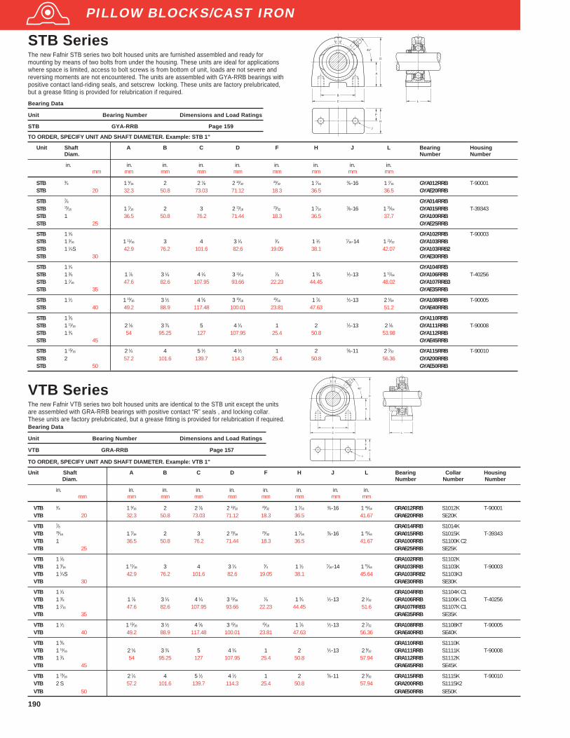
190
TO ORDER, SPECIFY UNIT AND SHAFT DIAMETER. Example: STB 1"
Unit Shaft A B C D F H J L Bearing HousingDiam. Number Number
in. in. in. in. in. in. in. in. in.mm mm mm mm mm mm mm mm mm
STB 3⁄4 1 5⁄16 2 2 7⁄8 2 13⁄3223⁄32 1 7⁄16
3⁄8-16 1 7⁄16 GYA012RRB T-90001STB 20 32.3 50.8 73.03 71.12 18.3 36.5 36.5 GYAE20RRB
STB 7⁄8 GYA014RRBSTB 15⁄16 1 7⁄16 2 3 2 13⁄16
23⁄32 1 7⁄163⁄8-16 1 31⁄64 GYA015RRB T-39343
STB 1 36.5 50.8 76.2 71.44 18.3 36.5 37.7 GYA100RRBSTB 25 GYAE25RRB
STB 1 1⁄8 GYA102RRB T-90003STB 1 3⁄16 1 11⁄16 3 4 3 1⁄4 3⁄4 1 1⁄2 7⁄16-14 1 21⁄32 GYA103RRBSTB 1 1⁄4S 42.9 76.2 101.6 82.6 19.05 38.1 42.07 GYA103RRB2STB 30 GYAE30RRB
STB 1 1⁄4 GYA104RRBSTB 1 3⁄8 1 7⁄8 3 1⁄4 4 1⁄4 3 11⁄16 7⁄8 1 3⁄4 1⁄2-13 1 57⁄64 GYA106RRB T-40256STB 1 7⁄16 47.6 82.6 107.95 93.66 22.23 44.45 48.02 GYA107RRB3STB 35 GYAE35RRB
STB 1 1⁄2 1 15⁄16 3 1⁄2 4 5⁄8 3 15⁄1615⁄16 1 7⁄8 1⁄2-13 2 1⁄64 GYA108RRB T-90005
STB 40 49.2 88.9 117.48 100.01 23.81 47.63 51.2 GYAE40RRB
STB 1 5⁄8 GYA110RRBSTB 1 11⁄16 2 1⁄8 3 3⁄4 5 4 1⁄4 1 2 1⁄2-13 2 1⁄8 GYA111RRB T-90008STB 1 3⁄4 54 95.25 127 107.95 25.4 50.8 53.98 GYA112RRBSTB 45 GYAE45RRB
STB 1 15⁄16 2 1⁄4 4 5 1⁄2 4 1⁄2 1 2 5⁄8-11 2 7⁄32 GYA115RRB T-90010STB 2 57.2 101.6 139.7 114.3 25.4 50.8 56.36 GYA200RRBSTB 50 GYAE50RRB
TO ORDER, SPECIFY UNIT AND SHAFT DIAMETER. Example: VTB 1"
Unit Shaft A B C D F H J L Bearing Collar HousingDiam. Number Number Number
in. in. in. in. in. in. in. in. in.mm mm mm mm mm mm mm mm mm
VTB 3⁄4 1 5⁄16 2 2 7⁄8 2 13⁄32 23⁄32 1 7⁄16 3⁄8-16 1 41⁄64 GRA012RRB S1012K T-90001VTB 20 32.3 50.8 73.03 71.12 18.3 36.5 41.67 GRAE20RRB SE20K
VTB 7⁄8 GRA014RRB S1014KVTB 15⁄16 1 7⁄16 2 3 2 13⁄16
23⁄32 1 7⁄163⁄8-16 1 41⁄64 GRA015RRB S1015K T-39343
VTB 1 36.5 50.8 76.2 71.44 18.3 36.5 41.67 GRA100RRB S1100K C2VTB 25 GRAE25RRB SE25K
VTB 1 1⁄8 GRA102RRB S1102KVTB 1 3⁄16 1 11⁄16 3 4 3 1⁄4 3⁄4 1 1⁄2 7⁄16-14 1 51⁄64 GRA103RRB S1103K T-90003VTB 1 1⁄4S 42.9 76.2 101.6 82.6 19.05 38.1 45.64 GRA103RRB2 S1103K3VTB 30 GRAE30RRB SE30K
VTB 1 1⁄4 GRA104RRB S1104K C1VTB 1 3⁄8 1 7⁄8 3 1⁄4 4 1⁄4 3 11⁄16 7⁄8 1 3⁄4 1⁄2-13 2 1⁄32 GRA106RRB S1106K C1 T-40256VTB 1 7⁄16 47.6 82.6 107.95 93.66 22.23 44.45 51.6 GRA107RRB3 S1107K C1VTB 35 GRAE35RRB SE35K
VTB 1 1⁄2 1 15⁄16 3 1⁄2 4 5⁄8 3 15⁄16 15⁄16 1 7⁄8 1⁄2-13 2 7⁄32 GRA108RRB S1108KT T-90005VTB 40 49.2 88.9 117.48 100.01 23.81 47.63 56.36 GRAE40RRB SE40K
VTB 1 5⁄8 GRA110RRB S1110KVTB 1 11⁄16 2 1⁄8 3 3⁄4 5 4 1⁄4 1 2 1⁄2-13 2 9⁄32 GRA111RRB S1111K T-90008VTB 1 3⁄4 54 95.25 127 107.95 25.4 50.8 57.94 GRA112RRB S1112KVTB 45 GRAE45RRB SE45K
VTB 1 15⁄16 2 1⁄4 4 5 1⁄2 4 1⁄2 1 2 5⁄8-11 2 9⁄32 GRA115RRB S1115K T-90010VTB 2 S 57.2 101.6 139.7 114.3 25.4 50.8 57.94 GRA200RRB S1115K2VTB 50 GRAE50RRB SE50K
VTB SeriesThe new Fafnir VTB series two bolt housed units are identical to the STB unit except the unitsare assembled with GRA-RRB bearings with positive contact “R” seals , and locking collar.These units are factory prelubricated, but a grease fitting is provided for relubrication if required.Bearing Data
Unit Bearing Number Dimensions and Load Ratings
VTB GRA-RRB Page 157
STB SeriesThe new Fafnir STB series two bolt housed units are furnished assembled and ready formounting by means of two bolts from under the housing. These units are ideal for applicationswhere space is limited, access to bolt screws is from bottom of unit, loads are not severe andreversing moments are not encountered. The units are assembled with GYA-RRB bearings withpositive contact land-riding seals, and setscrew locking. These units are factory prelubricated,but a grease fitting is provided for relubrication if required.
Bearing Data
Unit Bearing Number Dimensions and Load Ratings
STB GYA-RRB Page 159
A
D
B
C L
J
H
F
45°
A
D
C L
B
H
F
J
45°
PILLOW BLOCKS/CAST IRON

191
RAO, LAO Heavy SeriesFafnir RAO and LAO heavy type pillow blocks meet the need for acompact, economical, heavy duty ball bearing housed unit. Designedto incorporate the tested and proven features of the Fafnir standardRAK series pillow blocks, the RAO series is equipped with heavyseries GN-KRRB wide inner ring ball bearings for greater loadcapacity, and the LAO series is equipped with heavy series GN-KLLBwide inner ring bearings
All units are supplied with a self-locking collar which eliminatesshaft shoulders, machining adapters, sleeves, and locknuts andprovides easy mounting.
Recommended shaft tolerances: 1 3⁄16"-1 15⁄16", nominal to -.0005", -.013mm;
2"-2 15⁄16", nominal to -.0010", -.025mm.
Bearing Data
Unit Bearing Number Dimensions and Load Ratings
RAO GN-KRRB Page 155
LAO GN-KLLB Page 164
TO ORDER, SPECIFY UNIT AND SHAFT DIAMETER. Example: RAO 1 7⁄16"
Unit(1)
Shaft H H 2 B1 L1 J L A H 1 N N1 d1 S1 T Bolt Bearing Collar Housing UnitDiam. Size Number Number Number Wt.
in. in. in. in. in. in. in. in. in. in. in. in. in. in. in. lbsmm mm mm mm mm mm mm mm mm mm mm mm mm mm kg
RAO 1 3⁄16 1 7⁄8 3 11⁄16 1 31⁄32 3 9⁄16 5 3⁄8 6 13⁄16 1 15⁄167⁄8 5⁄8 3⁄4 1 15⁄16 1 9⁄32
31⁄321⁄2 GN103KRRB SN103K T-18798 4.18
47.63 93.7 50 90.5 136.5 173 49.2 22.2 15.9 19 49.2 32.5 24.6 12.7 1.898
RAO 1 7⁄16 2 1⁄8 4 3⁄32 2 1⁄32 4 6 7 9⁄16 2 1⁄8 15⁄165⁄8 3⁄4 2 3⁄16 1 5⁄16 1 1⁄16
1⁄2 GN107KRRB SN107K T-18626 5.3053.98 104 51.6 101.6 152.4 192.1 54 23.8 15.9 19 55.6 33.3 27 12.7 2.406
RAO 1 1⁄2 2 3⁄8 4 5⁄8 2 1⁄4 4 1⁄2 6 3⁄4 8 1⁄2 2 3⁄8 1 1⁄163⁄4 1 2 1⁄2 1 15⁄32 1 3⁄16
5⁄8 GN108KRRB SN108K T-18800 8.2760.33 117.5 57.2 114.3 171.4 215.9 60.3 27 19 25.4 63.5 37.3 30.2 15.9 3.755
RAO 1 11⁄16 2 5⁄8 5 1⁄8 2 5⁄16 5 7 1⁄2 9 7⁄16 2 5⁄8 1 3⁄16 3⁄4 1 2 3⁄4 1 17⁄32 1 5⁄16 5⁄8 GN111KRRB SN111K T-18802 11.0866.68 130.2 58.7 127 190.5 239.7 66.7 30.2 19 25.4 69.8 38.9 33.3 15.9 5.03
RAO 1 15⁄16 2 13⁄16 5 9⁄16 2 5⁄8 5 7⁄16 8 1⁄4 10 7⁄16 2 7⁄8 1 5⁄16 3⁄4 1 3 1 21⁄32 1 7⁄16 5⁄8 GN115KRRB SN115K T-18804 13.8071.44 141.3 66.7 138.1 209.6 265.1 73 33.3 19 25.4 76.2 42.1 36.5 15.9 6.265
RAO 2 3⁄16 3 1⁄16 6 1⁄32 2 7⁄8 5 15⁄16 9 11 5⁄16 3 1⁄8 1 7⁄16 7⁄8 1 1⁄8 3 1⁄4 1 25⁄32 1 9⁄16 3⁄4 GN203KRRB SN203K T-18806 17.4977.79 153.2 73 150.8 228.6 287.3 79.4 36.5 22.2 28.6 82.6 45.2 39.7 19 7.94
RAO 2 7⁄16 3 5⁄16 6 17⁄32 3 1⁄8 6 7⁄16 9 3⁄4 12 5⁄16 3 5⁄16 1 1⁄2 7⁄8 1 1⁄8 3 1⁄2 1 29⁄32 1 21⁄32 3⁄4 GN207KRRB SN207K T-18808 21.5084.14 165.9 79.4 163.5 247.6 312.7 84.1 38.1 22.2 28.6 88.9 48.4 42.1 19 9.761
RAO 2 11⁄16 3 13⁄16 7 9⁄16 3 1⁄2 7 7⁄16 11 1⁄4 14 3⁄16 3 13⁄16 1 3⁄4 1 1 5⁄16 4 2 5⁄32 1 29⁄32 7⁄8 GN211KRRB SO211K T-18810 33.7596.84 192.1 88.9 188.9 285.8 360.4 96 44.4 25.4 33.3 101.6 54.8 48.4 22.2 15.322
RAO 2 15⁄16 4 1⁄8 8 1⁄16 3 15⁄16 7 15⁄16 12 15 1⁄8 4 1⁄16 1 7⁄8 1 1 5⁄16 4 7⁄16 2 15⁄32 2 1⁄32 7⁄8 GN215KRRB SN215K T-18601 40.10104.78 204.8 100 201.6 304.8 384.2 103.2 47.6 25.4 33.3 112.7 62.7 51.6 22.2 18.205
(1) LAO assembled with GN-KLLB bearing.
J
L
L
H1
H
N
N1
1
H2
S
A
B
d
T
1
1
1
PIPE PLUG
18/
PILLOW BLOCKS/CAST IRON

192
RSA, LSA Industrial SeriesFafnir RSA and LSA type pillow blocks are equipped with G-KRRBwide inner ring ball bearings, and the LSA series is equipped with G-KLLB wide inner ring bearings.
These pillow blocks are prelubricated and ready for immediateuse. A grease fitting is provided for relubrication if required. All unitsare supplied with a self locking collar.
Recommended shaft tolerances: 1⁄2"-1 15⁄16", nominal to -.0005", -.013mm;
2"-2 15⁄16", nominal to -.0010", -.025mm.
Bearing Data
Unit Bearing Number Dimensions and Load Ratings
RSA G-KRRB Page 154
LSA G-KLLB Page 164
TO ORDER, SPECIFY UNIT AND SHAFT DIAMETER. Example: RSA 1 7⁄16", POPULAR SIZES IN BOLD
Unit Shaft H H 2 B1 L1 J L A H 1 N N1 d1 S1 Bolt Bearing Collar Housing Unit Wt.Diam. Size Number Number Number
in. in. in. in. in. in. in. in. in. in. in. in. in. in. lbsmm mm mm mm mm mm mm mm mm mm mm mm mm mm kg
RSA 1⁄2 G1008KRRB S1008KRSA 5⁄8 1 1⁄4 2 5⁄16 1 15⁄32 2 1⁄8 3 13⁄16 4 13⁄16 1 1⁄4 1⁄2 7⁄16
9⁄16 1 3⁄1659⁄64
3⁄8 G1010KRRB S1010K T-22784 1.50RSA 11⁄16 31.75 58.7 37.3 54 96.8 122.2 31.8 12.7 11.1 14.3 30.2 23.4 9.5 G1011KRRB S1011K 0.681RSA 17 GE17KRRB SE17K
RSA 3⁄4 1 3⁄4 3 1 23⁄32 2 1⁄2 5 6 1⁄2 2 9⁄169⁄16
3⁄4 1 5⁄16 1 3⁄641⁄2 G1012KRRB S1012K T-22741 2.70
RSA 20 44.45 76.2 43.7 63.5 127.0 165.1 50.8 14.3 14.3 19 33.3 26.6 12.7 GE20KRRB SE20K 1.226
RSA 7⁄8 G1014KRRB S1014KRSA 15⁄16 2 3 3⁄8 1 3⁄4 2 3⁄4 5 1⁄2 7 2 1⁄8 5⁄8 9⁄16
3⁄4 1 1⁄2 1 1⁄161⁄2 G1015KRRB S1015K T-22716 3.35
RSA 1 50.80 85.7 44.4 69.8 139.7 177.8 54 15.9 14.3 19 38.1 27 12.7 G1100KRRB S1100K 1.521RSA 25 GE25KRRB SE25K
RSA 1 1⁄16 G1101KRRB S1101KRSA 1 1⁄8 2 3 19⁄32 1 29⁄32 3 3⁄16 5 1⁄2 7 2 1⁄8 11⁄16 5⁄8 13⁄16 1 47⁄64 1 3⁄16 1⁄2 G1102KRRB S1102K T-22725 3.94RSA,LSA 13⁄16 50.80 91.3 48.4 81 139.7 177.8 54 17.5 15.9 20.6 44.1 30.2 12.7 G1103KRRB S1103K 1.789RSA 30 GE30KRRB SE30K
RSA,LSA 1 1⁄4 G1104KRRB S1104KRSA 1 5⁄16 2 3⁄8 4 3⁄8 2 1⁄64 4 6 1⁄4 8 1⁄4 2 5⁄8 7⁄8 3⁄4 1 1⁄4 2 1⁄8 1 9⁄32 5⁄8 G1105KRRB S1105K T-22382 7.18RSA 1 3⁄8 60.33 111.1 51.2 101.6 158.8 209.6 66.7 22.2 19 31.8 54 32.5 15.9 G1106KRRB S1106K 3.260RSA,LSA 17⁄16 G1107KRRB S1107KRSA 35 GE35KRRB SE35K
RSA 11⁄2 2 3⁄8 4 3⁄8 2 7⁄32 4 6 5⁄8 8 1⁄4 2 3⁄8 3⁄4 3⁄4 7⁄8 2 3⁄8 1 3⁄8 5⁄8 G1108KRRB S1108KT T-22752 6.45RSA 1 9⁄16 60.33 111.1 56.4 101.6 168.3 209.6 60.3 19 19 22.2 60.3 34.9 15.9 G1109KRRB S1109KT 2.928RSA 40 GE40KRRB SE40K
RSA 1 5⁄8 G1110KRRB S1110KRSA,LSA 111⁄16 2 3⁄8 4 1⁄2 2 7⁄32 4 1⁄4 6 5⁄8 8 1⁄4 2 3⁄8 13⁄16 3⁄4 15⁄16 2 1⁄2 1 3⁄8 5⁄8 G1111KRRB S1111K T-22701 6.75RSA 1 3⁄4 60.33 114.3 56.4 108 168.3 209.6 60.3 20.6 19 23.8 63.5 34.9 15.9 G1112KRRB S1112K 3.064RSA 45 GE45KRRB SE45K
RSA 1 7⁄8 2 3⁄4 5 1⁄8 2 15⁄32 4 3⁄4 8 1⁄4 10 5⁄8 2 3⁄4 1 1⁄32 3⁄4 1 3⁄8 2 3⁄4 1 1⁄2 5⁄8 G1114KRRB S1114K T-22384 10.76RSA,LSA 115⁄16 69.85 130.2 62.7 120.6 209.6 269.9 69.8 26.2 19 34.9 69.8 38.1 15.9 G1115KRRB S1115K 4.885RSA 50 GE50KRRB SE50K
RSA 2 G1200KRRB S1200KRSA 2 1⁄8 3 1⁄8 5 19⁄32 2 13⁄16 4 15⁄16 9 11 3⁄8 3 1⁄8 1 3⁄4 1 5⁄16 3 1 23⁄32 5⁄8 G1202KRRB S1202K T-22696 13.22RSA,LSA 2 3⁄16 79.38 142.1 71.4 125.4 228.6 288.9 79.4 25.4 19 33.3 76.2 43.7 15.9 G1203KRRB S1203K 6.022RSA 55 GE55KRRB SE55K
RSA 2 1⁄4 G1204KRRB S1204KRSA 2 3⁄8 3 1⁄8 5 7⁄8 3 1⁄16 5 1⁄2 9 11 3⁄8 3 1⁄8 1 1⁄8 7⁄8 1 1⁄8 3 5⁄16 1 27⁄32 3⁄4 G1206KRRB S1206K T-22743 15.20RSA,LSA 2 7⁄16 79.38 149.2 77.8 139.7 228.6 288.9 79.4 28.6 22.2 28.6 84.1 46.8 19 G1207KRRB S1207K 6.901RSA 60 GE60KRRB SE60K
RSA 2 11⁄16 3 3⁄4 6 13⁄16 3 1⁄4 6 1⁄8 10 1⁄4 12 5⁄8 3 1⁄2 1 5⁄16 7⁄8 1 3⁄8 3 13⁄16 1 25⁄32 3⁄4 G1211KRRB S1211KT T-22748 22.02RSA 70 95.25 173 82.6 155.6 260.4 320.7 88.9 33.3 22.2 34.9 96.8 45.2 19 GE70KRRB SE70K 9.997
RSA 2 15⁄16 3 3⁄4 7 3 5⁄8 7 23⁄32 10 1⁄4 12 5⁄8 3 1⁄2 1 1⁄2 7⁄8 1 1⁄4 4 2 5⁄32 3⁄4 G1215KRRB S1215K T-22386 23.53RSA 75 95.25 177.8 92.1 196.1 206.4 320.7 88.9 38.1 22.2 31.8 101.6 54.8 19 GE75KRRB SE75K 10.683
FAFNIR
J
L
L
H
H
1
H
45°
N
N1
1
2
A
d1
S
B
1
1
PILLOW BLOCKS/CAST IRON

193
RSAO, LSAO Heavy SeriesFafnir RSAO and LSAO type pillow blocks are equipped with GN-KRRB wide inner ring ball bearings, and the LSA series is equippedwith GN-KLLB wide inner ring bearings. They are ideally suited forinstallations where the load is heavy in proportion to the shaftdiameter or where considerable shock loads exist.
These pillow blocks are prelubricated and ready for immediate use.For wet or extremely dirty conditions, a grease fitting is provided forrelubrication if required. All units are supplied with a self locking collar.
Recommended shaft tolerances: 1 1⁄16"-1 15⁄16", nominal to -.0005", -.013mm;
2"-3 15⁄16", nominal to -.0010", -.025mm.
Bearing Data
Unit Bearing Number Dimensions and Load Ratings
RSAO GN-KRRB Page 155
LSAO GN-KLLB Page 164
TO ORDER, SPECIFY UNIT AND SHAFT DIAMETER. Example: RSAO 1 7⁄16"
Unit Shaft H H 2 B1 L1 J L A H 1 N N1 d1 S1 Bolt Bearing Collar Housing Unit Wt.
Diam. Size Number Number Number
in. in. in. in. in. in. in. in. in. in. in. in. in. in. lbsmm mm mm mm mm mm mm mm mm mm mm mm mm kg
RSAO,LSAO 1 3⁄16 2 3⁄8 4 1⁄4 1 31⁄32 3 3⁄4 6 5⁄8 8 1⁄4 2 3⁄8 7⁄8 5⁄8 1 1 15⁄16 1 9⁄32 1⁄2 GN103KRRB SN103K T-22678 6.4760.33 108 50 95.2 168.3 209.6 60.3 22.2 15.9 25.4 49.2 32.5 12.7 2.937
RSAO,LSAO 1 7⁄16 2 3⁄4 4 13⁄16 2 1⁄32 4 1⁄8 8 1⁄4 10 5⁄8 2 3⁄4 15⁄16 3⁄4 1 1⁄8 2 3⁄16 1 5⁄16 5⁄8 GN107KRRB SN107K T-22496 9.1569.85 122.2 51.6 104.8 209.6 269.9 69.8 23.8 19 28.6 55.6 33.3 15.9 4.154
RSAO,LSAO 1 1⁄2 3 1⁄8 5 3⁄8 2 1⁄4 4 1⁄2 9 11 3⁄8 3 1⁄8 1 1⁄16 3⁄4 1 1⁄8 2 1⁄2 1 15⁄32 5⁄8 GN108KRRB SN108K T-22672 12.9079.38 136.6 57.2 114.3 228.6 288.9 79.4 27 19 28.6 63.5 37.3 15.9 5.857
RSAO,LSAO 1 11⁄16 3 1⁄8 5 5⁄8 2 5⁄16 5 9 11 3⁄8 3 1⁄8 1 3⁄16 3⁄4 1 1⁄8 2 3⁄4 1 17⁄32 5⁄8 GN111KRRB SN111K T-22498 14.45RSAO 1 3⁄4 79.38 142.9 58.7 127 228.6 288.9 79.4 30.2 19 28.6 69.8 38.9 15.9 GN112KRRB SN112K 6.56
RSAO,LSAO 1 15⁄16 3 1⁄8 5 27⁄32 2 5⁄8 5 7⁄16 9 11 3⁄8 3 1⁄8 1 5⁄16 3⁄4 1 1⁄8 3 1 21⁄32 5⁄8 GN115KRRB SN115K T-22502 15.9679.38 148.4 66.7 138.1 228.6 288.9 79.4 33.3 19 28.6 76.2 42.1 15.9 7.246
RSAO,LSAO 2 3⁄16 3 3⁄4 6 23⁄32 2 7⁄8 5 15⁄16 10 1⁄4 12 5⁄8 3 1⁄2 1 7⁄16 7⁄8 1 3⁄8 3 1⁄4 1 25⁄32 3⁄4 GN203KRRB SN203K T-22500 22.4595.25 170.7 73 150.8 260.4 320.7 88.9 36.5 22.2 34.9 82.6 45.2 19 10.192
RSAO,LSAO 2 7⁄16 4 1⁄8 7 11⁄32 3 1⁄8 6 7⁄16 11 1⁄4 13 3⁄4 4 1 1⁄2 7⁄8 1 3⁄8 3 1⁄2 1 29⁄32 3⁄4 GN207KRRB SN207K T-22494 35.56104.78 186.5 79.4 163.5 285.8 349.2 101.6 38.1 22.2 34.9 88.9 48.4 19 16.144
RSAO,LSAO 2 11⁄16 4 9⁄16 8 9⁄32 3 1⁄2 7 7⁄16 12 15 3⁄8 4 3⁄8 1 3⁄4 1 1 3⁄8 4 2 5⁄32 7⁄8 GN211KRRB SO211K T-22492 42.50115.89 210.3 88.9 188.9 304.8 390.5 111.1 44.4 25.4 34.9 101.6 54.8 22.2 19.295
RSAO,LSAO 2 15⁄16 4 9⁄16 8 9⁄16 3 15⁄16 8 12 3⁄8 15 3⁄8 4 3⁄8 1 7⁄8 1 1 3⁄8 4 7⁄16 2 15⁄32 7⁄8 GN215KRRB SN215K T-22490 44.25115.89 217.5 100 203.2 314.3 390.5 111.1 47.6 25.4 34.9 112.7 62.7 22.2 20.09
RSAO 3 3⁄16 4 9⁄16 8 25⁄32 4 3⁄16 8 7⁄16 12 3⁄8 15 3⁄8 4 3⁄8 1 15⁄16 1 1 3⁄4 4 11⁄16 2 19⁄32 7⁄8 GN303KRRB SN303K T-22444 50.25115.89 223 106.4 214.3 314.3 390.5 111.1 49.2 25.4 44.4 119.1 65.9 22.2 22.814
RSAO 3 7⁄16 5 1⁄8 9 7⁄8 4 9⁄16 9 1⁄2 13 3⁄8 16 1⁄8 4 3⁄4 2 1⁄4 1 1⁄8 2 1⁄8 5 1⁄4 2 29⁄32 1 GN307KRRB SN307K T-22446 68.25130.18 250.8 115.9 241.3 339.7 409.6 120.6 57.2 28.6 54 133.4 73.8 25.4 30.986
RSAO 3 15⁄16 5 11⁄16 11 1⁄16 5 1⁄16 10 3⁄4 14 3⁄4 17 5⁄16 5 1⁄8 2 9⁄16 1 1⁄8 1 3⁄4 5 3⁄4 3 3⁄32 1 GN315KRRB SN315K T-22448 89.50144.46 281 128.6 273 374.6 439.7 130.2 65.1 28.6 44.4 146 78.6 25.4 40.633
PILLOW BLOCKS/CAST IRON
FAFNIR
J
L
L
H1
H
N
N1
H2
1
A
d1
S
B
1/8 PIPE PLUG
1
1

194
SAL Industrial SeriesFixed & Floating TypesFafnir SAL type pillow blocks are designed for applications wherehigher-than-usual temperatures are encountered and for normaltemperature applications where for any reason one or more floatingbearing units are required. The floating unit allows its bearing to moveaxially as the shaft expands because of the temperature rise, while thefixed unit maintains shaft location. Bearings also have loose internal fit.
The SAL unit is equipped with a self-aligning SM wide inner ringbearing and a self-locking collar. An external aligning ring is fitted to thespherical surface of the outer ring.
They are equipped with oil-tight seals and are normally fitted for oillubrication, but can be equipped for grease lubrication when specified.
Note: Lubricate with high grade automotive or turbine oil, orball bearing grease before installation.
All units are assembled with a spacer ring (Fixed type). By removingthe spacer ring, the assembly becomes a floating unit.
Recommended shaft tolerances: 1 3⁄16"- 1 15⁄16", nominal to -.0005", -.013mm;
2"- 3 15⁄16", nominal to -.0010", -.025mm.
FLOAT MOUNTING
FIXEDMOUNTING
JL
N
N
L
H
H
1
1
1 O
A
A T1
PILLOW BLOCKS/CAST IRON
TO ORDER, SPECIFY UNIT, SHAFT DIAMETER, AND WHETHER FIXED OR FLOATING. Example: SAL 1 7⁄16"(one fixed, one floating).
Unit Shaft Total H O L 1 A J L N N 1 H1 A1 T Bolt Bearing Collar Housing UnitDiam. Float Size Number Number Number Wt.
in. in. in. in. in. in. in. in. in. in. in. in. in. in. lbmm mm mm mm mm mm mm mm mm mm mm mm mm kg
SAL 1 3⁄16 1⁄4 2 3 27⁄32 3 13⁄16 2 1⁄8 5 1⁄2 7 5⁄8 3⁄4 11⁄16 2 7⁄32 1 5⁄8 1⁄2 SM1103KS S1103K T-12127 8.306.4 50.8 97.6 96.8 54 139.7 177.8 15.9 19 17.5 56.4 41.3 12.7 3.768
SAL 1 1⁄4 1⁄4 2 3⁄8 4 1⁄8 4 1⁄4 2 3⁄8 6 1⁄4 8 1⁄4 3⁄4 1 3⁄4 2 15⁄32 1 21⁄32 5⁄8 SM1104KS S1104K T-13108 11.546.4 60.33 104.8 108 60.3 158.8 210 19 25.4 19 62.7 42.1 15.9 5.239
SAL 1 7⁄16 1⁄4 2 3⁄8 4 1⁄8 4 1⁄4 2 3⁄8 6 1⁄4 8 1⁄4 3⁄4 1 3⁄4 2 15⁄32 1 21⁄32 5⁄8 SM1107KS S1107K T-13108 11.546.4 60.33 104.8 108 60.3 158.8 210 19 25.4 19 62.7 42.1 15.9 5.239
SAL 1 1⁄2 5⁄16 2 3⁄8 4 1⁄4 4 3⁄4 2 3⁄8 6 5⁄8 8 1⁄4 3⁄4 1 3⁄4 2 1⁄2 1 3⁄4 5⁄8 SM1108KTS S1108KT T-12121 13.537.9 60.33 108 120.6 60.3 168.3 210 19 25.4 19 63.5 44.4 15.9 6.143
SAL 1 11⁄16 5⁄16 2 3⁄8 4 11⁄32 4 3⁄4 2 3⁄8 6 5⁄8 8 1⁄4 3⁄4 1 3⁄4 2 19⁄32 1 3⁄4 5⁄8 SM1111KS S1111K T-12121 12.927.9 60.33 110.3 120.6 60.3 168.3 210 19 25.4 19 65.9 44.4 15.9 5.866
SAL 1 15⁄16 5⁄16 2 3⁄4 4 19⁄32 5 1⁄4 2 3⁄4 8 1⁄4 10 5⁄8 3⁄4 1 7⁄8 2 23⁄32 1 7⁄8 5⁄8 SM1115KS S1115K T-12313 17.877.9 69.85 116.7 133.4 69.8 210 269.9 19 25.4 22.2 69.1 47.6 15.9 8.113
SAL 2 3⁄16 5⁄16 3 1⁄8 5 13⁄32 5 3⁄4 3 1⁄8 9 11 3⁄8 3⁄4 1 7⁄8 3 1⁄8 2 9⁄32 5⁄8 SM1203KS S1203K A-5845 24.187.9 79.38 137.3 146 79.4 228.6 288.9 19 25.4 22.2 79.4 57.9 15.9 10.978
SAL 2 7⁄16 3⁄8 3 1⁄8 5 29⁄32 6 1⁄4 3 1⁄8 9 11 3⁄8 3⁄4 1 7⁄8 3 1⁄2 2 13⁄32 5⁄8 SM1207KS S1207K A-5083 28.409.5 79.38 150 158.8 79.4 228.6 288.9 19 25.4 22.2 88.9 61.1 15.9 12.894
SAL 2 11⁄16 9⁄32 3 3⁄4 6 5⁄32 6 3⁄4 3 1⁄2 10 1⁄4 12 5⁄8 7⁄8 1 1⁄8 1 1⁄16 3 5⁄8 2 17⁄32 3⁄4 SM1211KTS S1211K T-18940 35.027.1 95.25 156.4 171.4 88.9 259.7 320.7 22.2 28.6 27 92.1 64.3 19 15.889
SAL 2 15⁄16 25⁄64 3 3⁄4 6 27⁄32 7 1⁄2 3 1⁄2 10 1⁄4 12 5⁄8 7⁄8 1 1⁄8 1 1⁄16 3 31⁄32 2 7⁄8 3⁄4 SM1215KS S1215K A-5088 44.509.9 95.25 173.8 190.5 88.9 259.7 320.7 22.2 28.6 27 100.8 73 19 20.203
SAL 3 7⁄16 3⁄8 4 9⁄16 7 11⁄32 8 3⁄8 4 3⁄8 12 3⁄8 15 3⁄8 1 1 1⁄4 1 1⁄4 4 7⁄32 3 1⁄8 3⁄4 SM1307KS S1307K A-5206 73.759.5 115.89 186.5 212.7 111.1 314.3 390.6 25.4 31.8 31.8 107.2 79.4 19 33.482
Bearing Data
Unit Bearing Number Dimensions and Load Ratings
SAL SM-KS Page 171

195
SAOL Heavy SeriesFixed & Floating TypesFafnir SAOL type heavy series pillow blocks are designed for applica-tions where higher-than-usual temperature applications where for anyreason one or more floating bearing units required. The floating unitallows its bearing to move axially as the shaft expands because of thetemperature rise, while the fixed unit maintains shaft location. Bearingsalso have loose internal fit.
The SAOL unit is equipped with a heavy series, self-aligning SMNwide inner ring bearing and a self-locking collar. An external aligningring is fitted to the spherical surface of the outer ring.
They are equipped with oil-tight seals and are normally fitted for oillubrication, but can be equipped for grease lubrication when specified.
Note: Lubricate with high grade automotive or turbine oil, or ballbearing grease before installation.
All units are assembled with a spacer ring (Fixed type). By removingthe spacer ring, the assembly becomes a floating unit.
Recommended shaft tolerances: 1 13⁄16"- 1 15⁄16", nominal to -.0005", -.013mm;
2"- 3 15⁄16", nominal to -.0010", -.025mm.
Larger sizes, consult the Engineering Department.
J
L
H
H
N
N1
1
L1
FLOAT MOUNTING
FIXEDMOUNTING
O
A
A T1
PILLOW BLOCKS/CAST IRON
TO ORDER, SPECIFY UNIT, SHAFT DIAMETER, AND WHETHER FIXED OR FLOATING. Example: SAOL 1 7⁄16" (one fixed, one floating).
Unit Shaft Total H O L 1 A J L N N 1 H1 A1 T J1(1)
Bolt Bearing Collar Housing UnitDiam. Float No. Size Number Number Number Wt.
in. in. in. in. in. in. in. in. in. in. in. in. in. in. In. lbsmm mm mm mm mm mm mm mm mm mm mm mm mm mm kg
SAOL 1 3⁄165⁄16 2 3⁄8 4 1⁄16 4 3⁄8 2 3⁄8 6 5⁄8 8 1⁄4 5⁄8 7⁄8 11⁄16 2 3⁄8 1 11⁄16 — 2 1⁄2 SMN103KS SN103K T-12389 12.167.9 60.33 103.2 111.1 60.3 168.3 210 15.9 22.2 17.5 60.3 42.9 — 12.7 5.521
SAOL 1 7⁄1623⁄64 2 3⁄4 4 3⁄8 4 3⁄4 2 3⁄4 8 1⁄4 10 5⁄8 3⁄4 1 13⁄16 2 23⁄32 1 21⁄32 — 2 5⁄8 SMN107KS SN107K A-4779 15.59.1 69.8 111.1 120.6 69.8 209.6 269.9 19 25.4 20.6 69.1 42.1 — 12.9 7.037
SAOL 1 1⁄2 3⁄8 3 1⁄8 4 7⁄8 5 3⁄4 3 1⁄8 9 11 3⁄8 3⁄4 1 13⁄16 2 15⁄16 1 15⁄16 — 2 5⁄8 SMN108KS SN108K A-4778A 259.5 79.4 123.8 146 79.4 228.6 288.9 19 25.4 20.6 74.6 49.2 — 12.9 11.35
SAOL 1 11⁄163⁄8 3 1⁄8 4 7⁄8 5 3⁄4 3 1⁄8 9 11 3⁄8 3⁄4 1 13⁄16 2 15⁄16 1 15⁄16 — 2 5⁄8 SMN111KS SN111K A-4778 24.569.5 79.4 123.8 146 79.4 228.6 288.9 19 25.4 20.6 74.6 49.2 — 12.9 11.15
SAOL 1 15⁄163⁄8 3 1⁄8 4 13⁄16 6 1⁄4 3 1⁄8 9 11 3⁄8 3⁄4 1 13⁄16 2 29⁄32 1 29⁄32 — 2 5⁄8 SMN115KS SN115K A-3818 27.45
9.5 79.4 122.2 158.8 79.4 228.6 288.9 19 25.4 20.6 73.8 48.4 — 12.9 12.462
SAOL 2 3⁄1623⁄64 3 3⁄4 5 1⁄2 6 3⁄4 3 1⁄2 10 1⁄4 12 5⁄8 7⁄8 1 1⁄4 1 1⁄16 3 1⁄4 2 1⁄4 — 2 3⁄4 SMN203KS SN203K A-4755 33.949.1 95.25 139.7 171.4 88.9 259.7 320.7 22.2 31.8 27 82.6 57.2 — 19 15.409
SAOL 2 7⁄1611⁄32 4 1⁄8 5 29⁄32 7 1⁄2 4 11 1⁄4 13 3⁄4 7⁄8 1 1⁄4 1 1⁄16 3 19⁄32 2 5⁄16 — 2 3⁄4 SMN207KS SN207K A-3819 41.58.7 104.8 150 190.5 101.6 285.8 349.2 22.2 31.8 27 91.3 58.7 — 19 18.841
SAOL 2 11⁄163⁄8 4 9⁄16 6 7⁄8 8 1⁄2 4 3⁄8 12 15 3⁄8 1 1 1⁄4 1 1⁄4 4 5⁄16 2 9⁄16 — 2 7⁄8 SMN211KS SO211K A-4709 58
9.5 115.89 174.6 215.9 111.1 304.8 390.6 25.4 31.8 31.8 109.5 65.1 — 22.2 26.332
SAOL 2 15⁄161⁄2 4 9⁄16 7 8 7⁄8 4 3⁄8 12 3⁄8 15 3⁄8 1 1 1⁄4 1 1⁄4 4 1⁄8 2 7⁄8 — 2 7⁄8 SMN215KS SN215K A-4798 74.5
12.7 115.89 177.8 225.4 111.1 314.3 390.6 25.4 31.8 31.8 104.8 73 — 22.2 33.823
SAOL 3 3⁄1633⁄64 4 9⁄16 7 1⁄4 9 1⁄2 4 3⁄8 12 3⁄8 15 3⁄8 1 1 1⁄4 1 1⁄4 4 1⁄4 3 2 1⁄4 4 7⁄8 SMN303KS SN303K A-4780 77.7513.1 115.89 184.2 241.3 111.1 314.3 390.6 25.4 31.8 31.8 108 76.2 57.2 22.2 35.298
SAOL 3 7⁄1617⁄32 5 1⁄8 7 1⁄2 10 1⁄4 4 3⁄4 13 3⁄8 16 1⁄8 1 1 1⁄4 1 1⁄4 4 3⁄8 3 1⁄8 3 4 7⁄8 SMN307KS SN307K A-4155 107.513.5 130.2 190.5 260.4 120.6 339.7 409.6 25.4 31.8 31.8 111.1 79.4 76.2 22.2 48.805
SAOL 3 11⁄161⁄2 5 11⁄16 8 13⁄32 11 4 15⁄16 14 3⁄4 17 5⁄16 1 1⁄8 1 1⁄2 1 1⁄4 5 1⁄4 3 5⁄32 — 2 1 SMO311WS SO311K A-4156 120
12.7 144.5 213.5 279.4 125.4 374.6 439.7 28.6 38.1 31.8 133.4 80.2 — 25.4 54.48
SAOL 3 15⁄1611⁄16 6 8 21⁄32 11 3⁄4 5 1⁄4 15 1⁄2 18 1⁄2 1 1⁄8 1 1⁄2 1 3⁄8 5 3 21⁄32 3 1⁄4 4 1 SMN315KS SN315K A-4795 15617.5 152.4 219.9 298.4 133.4 393.1 469.9 28.6 38.1 34.9 127 92.9 82.6 25.4 70.824
SAOL 4 3⁄165⁄8 6 1⁄2 8 7⁄8 12 1⁄2 6 1⁄4 17 11⁄16 21 1⁄4 1 1⁄8 1 1⁄2 1 1⁄2 5 9⁄32 3 19⁄32 4 4 1 SMN403WS SN403K T-14342 194
15.9 165.1 225.4 317.5 158.8 449.3 539.8 28.6 38.1 38.1 134.1 91.3 101.6 25.4 88.076
SAOL 4 7⁄169⁄16 7 9 12 7⁄8 6 3⁄4 17 11⁄16 21 1⁄4 1 1⁄4 1 3⁄4 1 3⁄4 5 5⁄16 3 11⁄16 4 1⁄4 4 1 1⁄8 SMN407WS SN407K T-11469 210
14.3 177.8 228.6 327 171.4 449.3 539.8 31.8 44.4 44.4 134.9 93.6 108 28.6 95.34
SAOL 4 15⁄16 1 15⁄64 8 1⁄4 10 5⁄16 15 7 1⁄4 20 1⁄4 24 13⁄16 1 1⁄4 1 3⁄4 2 6 4 5⁄16 4 3⁄4 4 1 1⁄8 SMN415WS SN415K T-11783 35331.4 209.6 261.9 381 184.2 514.4 630.2 31.8 44.4 50.8 152.4 109.5 120.6 28.6 160.262
(1) When four bolts are used, dimension J1 is distance between centers, and A1 and T are measured from center of base.
Bearing Data
Unit Bearing Number Dimensions and Load Ratings
SAOL SMN-KS Page 172

217
PBS SeriesThe Fafnir PBS pillow block is an economical, versatile powertransmission unit designed for light duty, moderate speed require-ments.
The housing consists of two heavy gauge, zinc plated steelstampings, one of which is a standard stamping used in the MST two-bolt Flangette unit. RA-RRB (extended inner ring) bearings areregularly furnished with this housing, although RR (wide inner ring)bearings can also be used. The Fafnir originated self-locking collarcompletes the assembly.
PBS units are made with a precision bearing seat in whichdimensions are held to close tolerances to provide an accuratebearing-to-housing fit and to assure proper alignment of the parts.
The RA-RRB bearing used in the PBS pillow block has positivecontact land-riding seals with the improved shroud cap design and ispermanently prelubricated.
The base-to-center height and bolt spacing of PBS units makethem readily interchangeable with many standard pillow blocks on themarket.
Recommended shaft tolerances: nominal to -.0005", -.013mm.
POPULAR SIZES IN BOLD.
Bearing Data
Unit Bearing Number Dimensions and Load Ratings
PBS RA...RRB Page 156
TO ORDER - When ordering complete unit parts, specify unit and shaft diameter. i.e.; PBS 1". This will automatically include: ( 1) 52PBS Stamping, (1) 52MST-(ZP) Stamping, (1) RA 100-RRB bearing and collar.
Unit Shaft H J N 1 L H2 J1 d1 S1 O A H1 A1 A3 N2 P N Bearing Flangette Stamping UnitDiam. Number Number Radial Load Wt.
Rating(1)
in. in. in. in. in. in. in. in. in. in. in. in. in. in. in. in. in. lbsmm mm mm mm mm mm mm mm mm mm mm mm mm mm mm mm mm kg
PBS 1⁄2 1 3⁄16 3 5⁄8 5⁄8 4 7⁄8 2 11⁄32 2 1⁄2 1 1⁄8 7⁄8 9⁄16 1 0.104 0.075 1 9⁄32 9⁄32 13⁄32 13⁄32 RA008RRB 40 600 0.75PBS 5⁄8 30.2 92.1 15.9 123.8 59.5 63.5 28.6 22.2 14.3 25.4 2.64 1.9 32.5 7.1 10.3 10.3 RA010RRB MST-(ZP) 2650 0.34PBS 17 RAE17RRB
PBS 3⁄4 1 5⁄16 3 13⁄16 5⁄8 5 2 11⁄16 2 13⁄16 1 5⁄16 59⁄64 5⁄8 1 0.119 0.083 1 5⁄16 11⁄32 13⁄32 13⁄32 RA012RRB 47 700 0.97PBS 20 33.3 96.8 15.9 127 68.3 71.4 33.3 23.4 15.9 25.4 3.02 2.11 33.3 8.7 10.3 10.3 RAE20RRB MST-(ZP) 3100 0.44
PBS 7⁄8 RA014RRBPBS 15⁄16 1 7⁄16 3 3⁄4 13⁄16 5 1⁄4 2 27⁄32 3 1 1⁄2 59⁄64 11⁄16 1 0.134 0.083 1 11⁄32 11⁄32 7⁄16 7⁄16 RA015RRB 52 800 1.2PBS 1 36.5 95.2 20.6 133.4 72.2 76.2 38.1 23.4 17.5 25.4 3.4 2.11 34.1 8.7 11.1 11.1 RA100RRB MST-(ZP) 3550 0.544PBS 25 RAE25RRB
PBS 1 1⁄8 RA102RRBPBS 1 3⁄16 1 11⁄16 4 11⁄16 7⁄8 6 1⁄4 3 11⁄32 3 9⁄16 1 3⁄4 1 3⁄64 11⁄16 1 3⁄16 0.134 0.104 1 15⁄32 13⁄32 9⁄16 9⁄16 RA103RRB 62 800 1.64PBS 1 1⁄4S 42.9 119.1 22.2 158.8 84.9 90.5 44.4 26.6 17.5 30.2 3.4 2.64 37.3 10.3 14.3 14.3 RA103RRB2 MST-(ZP) 3550 0.744PBS 30 RAE30RRB
PBS 1 1⁄4 1 7⁄8 5 7⁄8 6 1⁄2 3 23⁄32 3 15⁄16 2 1⁄8 1 5⁄32 7⁄8 1 3⁄8 0.149 0.104 1 13⁄16 13⁄32 9⁄16 9⁄16 RA104RRB 72 900 2.4PBS 1 3⁄8 47.6 127 22.2 165.1 94.5 100 54 29.4 22.2 34.9 3.78 2.64 46 10.3 14.3 14.3 RA106RRB MST-(ZP) 4000 1.089PBS 1 7⁄16 RA107RRBPBS 35 RAE35RRB
(1) Stamping thrust rating is 1⁄5 of stamping radial load rating.
J
HOLE WIDTHTOL.
± .005
NH
J
L
1
H
d1
P
A
H
S
O
1
N
N1
22
1
A3
A1
PILLOW BLOCKS/PRESSED STEEL

218
(1)Bearing suffix number FS450.
(2)Housing thrust rating is 1⁄3 of housing radial load rating. Maximum recommended speed is 2400 RPM.
Recommended shaft tolerances: nominal to -.0005", -.013mm.
TO ORDER - specify unit and shaft diameter. i.e.; RPB 1 3⁄16". Popular sizes are in bold.
Unit Shaft H H 2 J L A H 1 N R d1 O S1 T Bearing Collar Stamping UnitDiam. Number Number Radial Load Wt.
Rating(1)
in. in. in. in. in. in. in. in. in. in. in. in. in. lbs lbsmm mm mm mm mm mm mm mm mm mm mm mm mm N kg
RPB 1⁄2 1 2 1⁄16 3 4 1⁄8 1 0.1 3⁄8 13⁄32 1 1⁄8 0.85 0.869 5⁄8 RA008RRB S1008K 200 0.44RPB 5⁄8 25.4 52.4 76.2 104.8 25.4 2.54 9.5 10.3 28.6 21.59 22.07 15.9 RA010RRB S1010K 880 0.2RPB 17 RAE17RRB SE17K
RPB 3⁄4 1 1⁄8 2 7⁄32 3 3⁄8 4 1⁄2 1 1⁄8 0.208 13⁄3213⁄32 1 5⁄16 1 0.923 9⁄16 RA012RRB S1012K 250 0.57
RPB 20 28.58 56.4 85.7 114 28.6 5.28 10.3 10.3 33.3 25.4 23.44 14.3 RAE20RRB SE20K 1120 0.259
RPB 7⁄8 RA014RRB S1014KRPB 15⁄16 1 5⁄16 2 5⁄8 3 3⁄4 4 7⁄8 1 1⁄4 0.145 7⁄16
13⁄32 1 1⁄2 1 0.923 3⁄4 RA015RRB S1015K 300 0.65RPB 1 33.34 66.7 95.2 123.8 31.8 3.68 11.1 10.3 38.1 25.4 23.44 19 RA100RRB S1100K 1340 0.295RPB 25 RAE25RRB SE25K
LRPB 13⁄16 1 5⁄16 2 5⁄8 3 3⁄4 4 7⁄8 1 1⁄4 0.145 7⁄1613⁄32 1 3⁄4 1 1.114 3⁄4 RAL103NPPB LS103K 300 1.05
33.34 66.7 95.2 123.8 31.8 3.68 11.1 10.3 44.4 25.4 28.3 19 1340 0.476
TO ORDER – specify unit and shaft diameter. i.e.; PBS 1 3⁄16". Popular sizes are in bold.
Unit Shaft H H 2 J L A H 1 N R d1 O S1 T Bearing Collar Stamping UnitDiam. Number Number Radial Load Wt.
Rating(1)
in. in. in. in. in. in. in. in. in. in. in. in. in. lbs lbsmm mm mm mm mm mm mm mm mm mm mm mm mm N kg
PB 1⁄2 7⁄8 1 3⁄4 2 11⁄16 3 5⁄8 1 0.1 3⁄8 11⁄32 1 1⁄8 0.718 0.869 1⁄2 RA008RRB S1008K 300 0.44PB 5⁄8 22.2 44.4 68.3 92.1 25.4 2.54 9.5 8.7 28.6 18.24 22.07 12.7 RA010RRB S1010K 1340 0.2PB 17 RAE17RRB SE17K
PB 3⁄4 1 2 1⁄16 3 4 1⁄8 1 0.1 3⁄8 13⁄32 1 5⁄16 0.859 0.923 5⁄8 RA012RRB S1012K 350 0.57PB 20 25.4 52.4 76.2 104.8 25.4 2.54 9.5 10.3 33.3 21.82 23.44 15.9 RAE20RRB SE20K 1560 0.259
PB 7⁄8 RA014RRB S1014KPB 15⁄16 1 1⁄8 2 7⁄32 3 3⁄8 4 1⁄2 1 1⁄8 0.208 13⁄32
13⁄32 1 1⁄2 1 0.923 9⁄16 RA015RRB S1015K 400 0.65PB 1 28.6 56.4 85.7 114 28.6 5.28 10.3 10.3 38.1 25.4 23.44 14.3 RA100RRB S1100K 1760 0.295PB 25 RAE25RRB SE25K
PB 1 1⁄8 RA102RRB S1102KPB 1 3⁄16 1 5⁄16 2 5⁄8 3 3⁄4 4 7⁄8 1 1⁄4 0.145 7⁄16
13⁄32 1 3⁄4 1 1.052 3⁄4 RA103RRB S1103K 600 1.05PB 1 1⁄4S 33.3 66.7 95.2 123.8 31.8 3.68 11.1 10.3 44.5 25.4 26.72 19 RA103RRB2 S1103K3 2650 0.476PB 30 RAE30RRB SE30K
(1)
Housing thrust rating is 1⁄3 of housing radial load rating. Load ratings are upright mounted capacities with load direction toward base.These units should not be mounted vertically or upside down.
PB SeriesRPB SeriesThe Fafnir PB pillow block is designed for extra light duty applications toprovide the advantages of ball bearings at low cost. The unit consists of atwo piece separable zinc plated steel housing with spherical bearing seat.This allows the spherically ground bearing initial self-alignment in alldirections.
The ball bearing is a RA-RRB extended inner ring type bearing and haspositive contact land-riding seals and self-locking collar. It incorporates theimproved shroud cap design and is permanently prelubricated.
The RPB type pillow block has the same construction as the PB type, buthas a thick, electrically conductive rubber interliner. Bearings in the RPB unitare designated as RA-RRB FS-450 and have a special ball and race finishfor exceptionally quiet operation. The bearing together with the rubberinterliner comprise a RABR unit. Bearing is permanently prelubricated.
Recommended shaft tolerances: nominal to -.0005", -.013mm.
Bearing Data
Unit Bearing Number Dimensions and Load Ratings
PB RA...RRB Page 156
RPB RA...RRB Page 156
O
d1
S
J
L
R
N 2 HOLES
AH
H
H
1
1
2
T
RPB Series
O
d1
S
J
L
R
N 2 HOLES
AH
H
H
1
1
2
T
PB Series
PILLOW BLOCKS/PRESSED STEEL

227
Unit H H 2 G L1 J L A H 1 N G1 d1 Bearing Collar Housing Approx.Number‡§ Number‡ Radial Load* Wt.
RatingRBG RBGU
in. in. in. in. in. in. in. in. in. in. in. lbs. lbs. lbs.
RBG, RBGU 3⁄4 1 1⁄4 2 1⁄2 1 15⁄32 2 1⁄2 3 1⁄2 4 5⁄8 1 1⁄8 5⁄8 31⁄6411⁄32 1 15⁄16 RA012RR§ S1012K 50 1.5 1.75
RBG, RBGU 15⁄16 1 5⁄16 2 11⁄16 1 19⁄32 2 3⁄4 3 7⁄8 5 1 1⁄4 5⁄8 31⁄6411⁄32 1 1⁄2 RA015RR§ S1015K 60
RBG, RBGU 1 1 5⁄16 2 11⁄16 1 19⁄32 2 3⁄4 3 7⁄8 5 1 1⁄4 5⁄8 31⁄6411⁄32 1 1⁄2 RA100RR§ S1100K 60 1.8 2
RBG, RBGU 1 3⁄16 1 9⁄16 3 5⁄32 1 3⁄4 3 3⁄16 4 1⁄2 6 1 3⁄8 3⁄4 39⁄643⁄8 1 47⁄64 RA103RR§ S1103K 90 2.75 3.1
* Load ratings for RBGU pillow blocks are approximately twice the above figures.§ Suffix for RA -RR bearing is FS450.
TO ORDER, SPECIFY UNIT AND SHAFT DIAMETER. Example: RS 1 3/16". POPULAR SIZES ARE IN BOLD.
Fafnir synthetic rubber pillow blocks are designed for domestic heating,air-conditioning, ventilating equipment and many other applications wherelow-cost, light-duty, and noiseless operation is essential. All units areavailable with the RA-RR extended inner ring bearings with positivecontact land-riding seals and self-locking collar. An initial supply of long-life grease is provided in the one-piece, non-relubricatable housings madeof high-grade, durable molded synthetic rubber.
Rubber pillow blocks with provision for relubrication are designated asthe RBG series. At slight additional cost, both can be supplied with a .050"to .062" thick corrosion-resistant steel strap for applications requiringgreater rigidity. When the strap is required, add the suffix U to the pillowblock designated as RGBU.
RBG, RBGU HVAC Special SeriesBearing Data
Unit Bearing Number Dimensions and Load Ratings
RS RA...RR Page 156
M
A
d
D
S
T1
1B1
FAFNIR
RS
J
L
L
H
N
SIZE
A
d
GG
SHAFTSIZE
RBG Type
H
1
1
1
H2
1
Unit Shaft D B 1 A M d1 S1 T Bearing Collar HousingDiam. Number (1) Number Radial Load
Rating (2)
in. in. in. in. in. in. in. in. lbsmm mm mm mm mm mm mm mm N
RABR 1⁄2 1.865 1 1⁄8 11⁄16 1 3⁄8 1 1⁄8 7⁄8 11⁄32 RA008RRB S1008K 200RABR 5⁄8 47.37 28.6 17.5 34.9 28.6 22.2 8.7 RA010RRB S1010K 880RABR 17 RAE17RRB SE17K
RABR 3⁄4 2.062 1 7⁄32 11⁄16 1 5⁄8 1 5⁄16 59⁄64 11⁄32 RA012RRB S1012K 250RABR 20 53.37 31 17.5 41.3 33.3 23.4 8.7 RAE20RRB SE20K 1120
RABR 15⁄16 2.456 1 7⁄32 13⁄16 1 27⁄32 1 1⁄2 59⁄64 13⁄32 RA015RRB S1015K 300RABR 1 62.38 31 20.6 46.8 38.1 23.4 10.3 RA100RRB S1100K 1340RABR 25 RAE25RRB SE25K
RABR 1 3⁄16 2.456 1 13⁄32 13⁄16 1 27⁄32 1 3⁄4 1 1⁄8 13⁄32 RAL103PP LS103K 300RABR 30 62.38 35.7 20.6 46.8 44.4 28.6 10.3 RAE30PP3 SE30K 1340
(1) For replacement of bearings, specify suffix FS-450. Maximum recommended speed is 2400 RPM.
(2) Thrust load is 1/3 radial load rating.
RABR HVAC Special Series
TO ORDER, SPECIFY UNIT AND SHAFT DIAMETER. Example: RABR 1". POPULAR SIZES ARE IN BOLD.
‡RBG units incorporate RB series bearings with RS locking collar. Example: Bearing and collarfor RBG 3/4" unit, specify RB012 bearing and RS012 collar.Special one ounce tubes of grease are available for relubrication.To order, specify: RBG 1 grease tubes.
The RABR unit features a conductive rubber interliner to dissapatestatic charges. Vibration and noise telegraphed by grounding springsare eliminated. Super quiet RA-RRB extended inner ring bearings areprelubricated and have positive contact, land-riding seals with self-locking collars. RABR units can be mounted in tri-arm brackets orpressed steel stampings.
Maximum recommended speed 2400 RPM.
Recommended housing diameter = Nominal (A) -.005", -.015", -.130mm -.380mm .
Bearing Data
Unit Bearing Number Dimensions and Load Ratings
RABR RA...RRB Page 156
RUBBER CARTRIDGES
DRNR . . . . . . . . . . . . . . . . . . . . . . . . . . . . . . . . . . . . 196
RC . . . . . . . . . . . . . . . . . . . . . . . . . . . . . . . . . . . . . . . 216
RCSM, RCR, CR . . . . . . . . . . . . . . . . . . . . . . . . . . . . 226
RABR, RBG Types . . . . . . . . . . . . . . . . . . . . . . . . . . 227
Idler Pulley Units . . . . . . . . . . . . . . . . . . . . . . . . . . . 232
Roller Chain Idler Sprockets . . . . . . . . . . . . . . . . . . 233
Fafnir Housed UnitsSpecial Duty

196
DRNR Industrial SeriesThe Fafnir double rigid pillow block, type DRNR, is designed toprovide a sturdy two-bearing mounting for fans and blowers, benchgrinders, buffers, vertical shafts and similar heavy duty applications.
The compact, one-piece housing is equipped with two Fafnir wideinner ring bearings with integral, R-seals and self-locking collar.
Individual grease chambers are provided for each bearing. Close-clearance baffles allow excess grease to work into the spaciouscenter chamber of the housing. Grease fittings installed in place ofthe standard pipe plugs will provide means of relubrication.
Type DRNR pillow blocks can be mounted in any position withample radial and thrust capacity assured at all times.
Recommended shaft tolerances: 15⁄16"-1 15⁄16", nominal to -.0005", -.013mm;
2"-2 3⁄16", nominal to -.0010", -.025mm.
Bearing Data
Unit Bearing Number Dimensions and Load Ratings
DRNR KR Page 153
TO ORDER, SPECIFY UNIT AND SHAFT DIAMETER. Example: DRNR 1 7⁄16"
Unit Shaft H H 2 O L1 J L A H 1 N N1 J1 d1 P Bolt Bearing Collar Housing Unit Wt.Diam. (4 req’d) Number Number Number
(2 req’d)
in. in. in. in. in. in. in. in. in. in. in. in. in. in. in. lbsmm mm mm mm mm mm mm mm mm mm mm mm mm mm mm kg
DRNR 15⁄16 2 1⁄2 3 29⁄32 7 7⁄8 2 13⁄16 6 1⁄4 7 3⁄4 4 1⁄4 3⁄4 1⁄2 5⁄8 2 3⁄4 1 1⁄2 5 3⁄4 3⁄8 1015KR S1015K T-19189 10.6063.5 99.2 200 71.4 158.8 196.8 108 19 12.7 15.9 69.8 38.1 146 9.5 4.812
DRNR 1 3⁄16 2 1⁄2 4 5⁄32 8 3 5⁄16 6 1⁄4 7 3⁄4 4 1⁄4 7⁄8 1⁄2 5⁄8 2 3⁄4 1 47⁄64 5 5⁄8 3⁄8 1103KR S1103K T-19191 11.3863.5 105.6 203.2 84.1 158.8 196.8 108 22.2 12.7 15.9 69.8 44.1 142.9 9.5 5.167
DRNR 1 7⁄16 3 4 7⁄8 10 7⁄8 3 3⁄4 8 10 5 1⁄2 1 5⁄8 7⁄8 3 1⁄2 2 1⁄8 8 21⁄641⁄2 1107KR S1107K T-19193 21.20
76.2 123.8 276.2 95.2 203.2 254 139.7 25.4 15.9 22.2 88.9 54 211.5 12.7 9.625
DRNR 1 11⁄16 3 5 1⁄4 11 4 1⁄2 8 10 5 1⁄2 1 5⁄8 7⁄8 3 1⁄2 2 1⁄2 8 1⁄4 1⁄2 1111KR S1111K T-19197 25.7576.2 133.4 279.4 114.3 203.2 254 139.7 25.4 15.9 22.2 88.9 63.5 209.6 12.7 11.69
DRNR 1 15⁄16 3 1⁄2 5 5⁄16 13 7⁄8 4 7⁄8 9 1⁄2 12 7 1 1⁄8 11⁄16 1 1⁄8 4 1⁄2 2 3⁄4 10 7⁄8 5⁄8 1115KR S1115K T-19195 41.5088.9 150.8 352.4 123.8 241.3 304.8 177.8 28.5 17.5 28.5 114.3 69.8 276.2 15.9 18.841
DRNR 2 3⁄16 3 1⁄2 6 1⁄4 14 5 1⁄4 9 1⁄2 12 7 1 1⁄4 11⁄16 1 1⁄8 4 1⁄2 3 10 9⁄165⁄8 1203KR S1203K A-9598 52.00
88.9 158.8 355.6 133.4 241.3 304.8 177.8 31.8 17.5 28.5 114.3 76.2 268.3 15.9 23.608
BOLT SIZE
N
N1
J
A
P
O
H
1
d1
J
L
H
H
L
1
1
2
PILLOW BLOCKS/CAST IRON

216
RC SeriesFafnir RC series Cylindrical Cartridges are convienient units formounting in straight bore housings. They incorporate a wide innerring bearing with self-locking collar and spherical outside diameterwhich is fitted to a corresponding spherical seat in the cartridge toprovide self-alignment.
RC Cylindrical Cartridges are equipped with a G-KRRB (R-Seal)wide inner ring ball bearing.
D ±.001
E
A
S1
1
Unit Shaft D A E 1 S1 Bearing Collar Housing Unit Wt.Diam. Number Number Number
in. in. in. in. in. lbsmm mm mm mm mm kg
RC 1⁄2 G1008KRRB S1008KRC 5⁄8 2 11⁄16 1 3⁄16
21⁄6459⁄64 G1010KRRB S1010K T-16793 1.21
RC 11⁄16 68.27 30.2 8.3 23.4 G1011KRRB S1011K 0.549RC 17 GE17KRRB SE17K
RC 3⁄4 2 15⁄16 1 7⁄1621⁄64 1 3⁄64 G1012KRRB S1012K T-16795 1.77
RC 20 74.61 36.5 8.3 26.6 GE20KRRB SE20K 0.804
RC 7⁄8 G1014KRRB S1014KRC 15⁄16 3 1⁄8 1 1⁄2 5⁄16 1 1⁄16 G1015KRRB S1015K T-16797 1.93RC 1 79.38 38.1 7.9 27 G1100KRRB S1100K 0.876RC 25 GE25KRRB SE25K
RC 1 1⁄16 G1101KRRB S1101KRC 1 1⁄8 3 1⁄2 1 1⁄2 7⁄16 1 3⁄16 G1102KRRB S1102K T-16798 2.58RC 1 3⁄16 88.9 38.1 11.1 30.2 G1103KRRB S1103K 1.171RC 30 GE30KRRB SE30K
RC 1 1⁄4 G1104KRRB S1104KRC 1 5⁄16 3 7⁄8 1 9⁄16 1⁄2 1 9⁄32 G1105KRRB S1105K T-16686 3.19RC 1 3⁄8 98.43 39.7 12.7 32.5 G1106KRRB S1106K 1.448RC 17⁄16 G1107KRRB S1107RC 35 GE35KRRB SE35K
RC 11⁄2 4 3⁄16 1 3⁄4 1⁄2 1 3⁄8 G1108KRRB S1108KT T-16800 4.12RC 1 9⁄16 106.36 44.4 12.7 34.9 G1109KRRB S1109KT 1.87RC 40 GE40KRRB SE40K
RC 1 5⁄8 G1110KRRB S1110KRC 111⁄16 4 3⁄8 1 3⁄4 1⁄2 1 3⁄8 G1111KRRB S1111K T-16687 4.34RC 1 3⁄4 111.13 44.4 12.7 34.9 G1112KRRB S1112K 1.97RC 45 GE45KRRB SE45K
RC 1 7⁄8 4 9⁄16 2 1⁄16 15⁄32 1 1⁄2 G1114KRRB S1114K T-16802 5.4RC 115⁄16 115.89 52.4 11.9 38.1 G1115KRRB S1115K 2.452RC 50 GE50KRRB SE50K
RC 2 G1200KRRB S1200KRC 2 1⁄8 4 15⁄16 2 5⁄16 9⁄16 1 23⁄32 G1202KRRB S1202K T-16804 6.97RC 23⁄16 125.41 58.7 14.3 43.7 G1203KRRB S1203K 3.164RC 55 GE55KRRB SE55K
RC 2 7⁄16 5 7⁄8 2 9⁄16 9⁄16 1 27⁄32 G1207KRRB S1207K T-17927 11.30RC 60 149.23 65.1 14.3 46.8 GE60KRRB SE60K 5.13
Recommended housing bore: Shaft Rotating - Nominal +.001" to +.013", +.025mm to +.076mm .Shaft Stationary- Nominal +.000" to +.002", +.00mm to +.050mm .Avoid excessive tightening of anchor bolts.
Recommended shaft tolerances: 1⁄2"-1 15/16", nominal to -.0005", -.013mm;2"-3 15⁄16", nominal to -.0010", -.025mm.
Bearing Data
Unit Bearing Number Dimensions and Load Ratings
RC G...KRRB Page 154
TO ORDER, SPECIFY UNIT AND SHAFT DIAMETER. Example: RC 1 3⁄16"; POPULAR SIZES IN BOLD.
All units have 1⁄4"-28 grease fittings.
CYLINDRICAL CARTRIDGES/CAST IRON

226
Unit Shaft D A A 1 G M d1 S1 T Bearing Collar Housing UnitDiam. Number (3) Number Radial Load Wt.
Rating (1)
in. in. in. in. in. in. in. in. in. lbs lbsmm mm mm mm mm mm mm mm mm N kg
RCSM SERIES Recommended Housing Diameter = Nominal D ± .005" ± .013mm
RCSM 1⁄2 2 17⁄32 1 — — 1 3⁄8 1 1⁄8 7⁄8 1⁄2 RA008RR S1008K 200 0.87RCSM 5⁄8 64.3 25.4 — — 34.9 28.6 22.2 12.7 RA010RR S1010K 880 0.395RCSM 17 RAE17RR SE17K
RCSM 3⁄4 2 17⁄32 1 — — 1 9⁄16 1 5⁄16 59⁄64 1⁄2 RA012RR S1012K 250 1.04RCSM 20 64.3 25.4 — — 39.7 33.3 23.4 12.7 RAE20RR SE20K 1120 0.472
RCSM 15⁄16 2 17⁄32 1 — — 1 25⁄32 1 1⁄2 59⁄641⁄2 RA015RR S1015K 300 1.16
RCSM 1 64.3 25.4 — — 45.2 38.1 23.4 12.7 RA100RR S1100K 1340 0.527RCSM 25 RAE25RR SE25K
LRCSM 1 3⁄16 2 17⁄32 1 — — 1 7⁄8 1 21⁄3225⁄32
1⁄2 RAL103NPP LS103K 300 1.3864.3 25.4 — — 47.6 42.1 19.8 12.7 1340 0.627
RCR SERIES Recommended Housing Diameter = Nominal D -.005" to -.0015", -0.13mm to -.038mm
LRCR 3⁄4 1 13⁄1623⁄32
5⁄8 — 1 3⁄8 1 3⁄1647⁄64
25⁄64 RAL012NPP LS012K 200 0.646 18.3 15.9 — 34.9 30.2 18.7 9.9 880 0.272
RCR 1 2 1⁄4 25⁄3211⁄16 — 1 3⁄4 1 1⁄2 59⁄64
25⁄64 RA100RR S1100K 300 0.9RCR 25 57.2 19.8 17.5 — 44.4 38.1 23.4 9.9 RAE25RR SE25K 1340 0.409
CR SERIES Recommended Housing Diameter 3.257 to 3.219", 82.73mm to 81.76mm
CR 3⁄4 3.29 1 7⁄8 1 27⁄64 1 9⁄16 1 5⁄1659⁄64
1⁄2 RA012RR S1012K 150 0.7CR 20 83.57 25.4 22.2 36.1 39.7 33.3 23.4 12.7 RAE20RR SE20K 670 0.318
CR 1 3.29 1 7⁄8 1 27⁄64 1 25⁄32 1 1⁄2 59⁄641⁄2 RA100RR S1100K 200 0.75
CR 25 83.57 25.4 22.2 36.1 45.2 38.1 23.4 12.7 RAE25RR SE25K 880 0.34
LCR 1 3.29 1 13⁄16 1 5⁄16 1 9⁄16 1 27⁄6425⁄32
9⁄16 RAL100NPP S1100K 200 0.68LCR 25 83.57 25.4 20.6 33.3 39.7 36.1 19.8 14.3 RALE25NPP SE25K 880 0.309
(1) Steady loads only. Thrust load is 1/3 radial load rating. Maximum recommended speed — 2400 RPM.
(3) Suffix for RA bearing is FS450 (RCSM and RCR Series).
TO ORDER, SPECIFY UNIT AND SHAFT DIAMETER. Example: RCSM 3⁄4" or RCR 3⁄4" or CR 3⁄4", POPULAR SIZES ARE IN BOLD.
M
A
d
D
S
1
1 T
M
A
d
D
S
A
45°
1
1
1 T
CR
Md
D
3.440
G
3 16/
1
A
A
1
TS1
RCSM RCR
RCSM, RCR, CR SeriesFafnir RCSM and RCR super-quiet, synthetic conductive rubbercylindrical cartridges are designed for domestic heating, air-conditioning, ventilating equipment and many other applicationswhere low-cost, light-duty, and noiseless operation is essential. Allunits are available with the RA-RRB extended inner ring bearingswith positive contact land-riding seals and self-locking collar. An initialsupply of long-life grease is provided in the one-piece, non-relubricatable cartridges made of high-grade, durable moldedsynthetic rubber.
The Fafnir patented CR unit was specifically designed toaccomodate the wide tolerances of either a hot or cold rolled #10gage (.134"), 3 1⁄2" O.D., electric resistance welded mechanicaltubing, such as that found in post office conveyor systems.
Bearing Data
Unit Bearing Number Dimensions and Load Ratings
RCSM, RCR, CR RA...RR Page 156
RUBBER CARTRIDGES
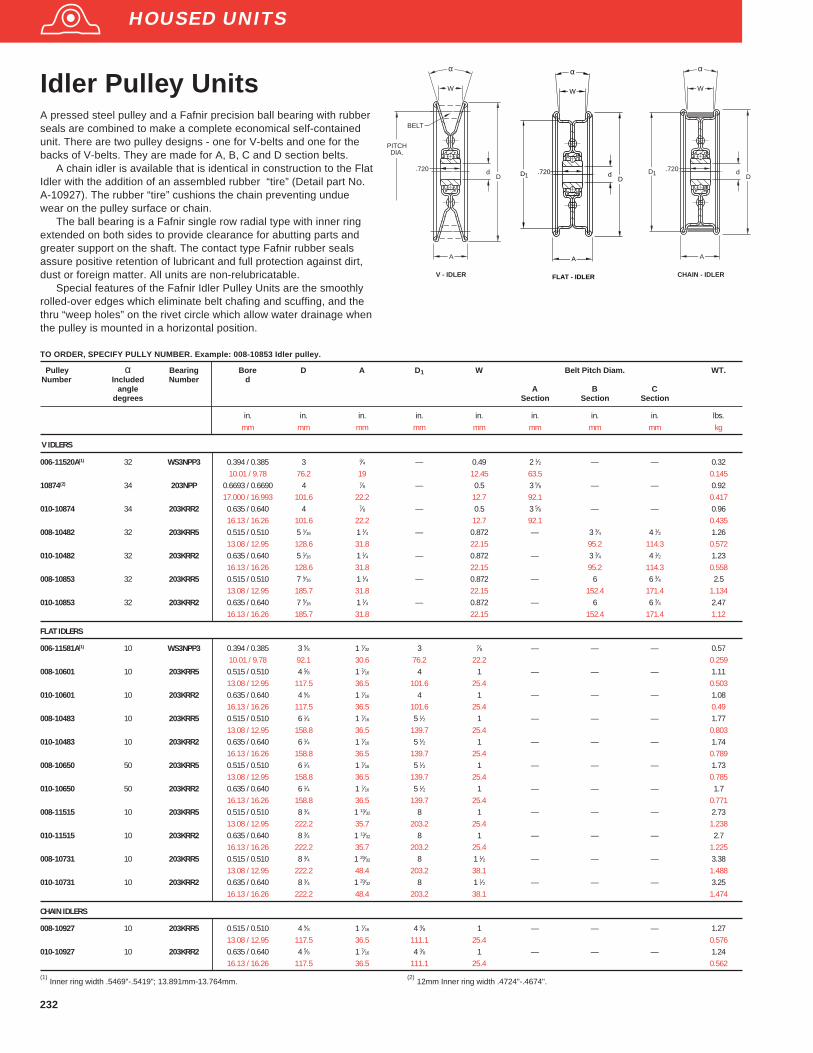
232
Pulley α Bearing Bore D A D 1 W Belt Pitch Diam. WT.Number Included Number d
angle A B Cdegrees Section Section Section
in. in. in. in. in. in. in. in. lbs.mm mm mm mm mm mm mm mm kg
V IDLERS
006-11520A(1) 32 WS3NPP3 0.394 / 0.385 3 3⁄4 — 0.49 2 1⁄2 — — 0.3210.01 / 9.78 76.2 19 12.45 63.5 0.145
10874(2) 34 203NPP 0.6693 / 0.6690 4 7⁄8 — 0.5 3 5⁄8 — — 0.9217.000 / 16.993 101.6 22.2 12.7 92.1 0.417
010-10874 34 203KRR2 0.635 / 0.640 4 7⁄8 — 0.5 3 5⁄8 — — 0.9616.13 / 16.26 101.6 22.2 12.7 92.1 0.435
008-10482 32 203KRR5 0.515 / 0.510 5 1⁄16 1 1⁄4 — 0.872 — 3 3⁄4 4 1⁄2 1.2613.08 / 12.95 128.6 31.8 22.15 95.2 114.3 0.572
010-10482 32 203KRR2 0.635 / 0.640 5 1⁄16 1 1⁄4 — 0.872 — 3 3⁄4 4 1⁄2 1.2316.13 / 16.26 128.6 31.8 22.15 95.2 114.3 0.558
008-10853 32 203KRR5 0.515 / 0.510 7 5⁄16 1 1⁄4 — 0.872 — 6 6 3⁄4 2.513.08 / 12.95 185.7 31.8 22.15 152.4 171.4 1.134
010-10853 32 203KRR2 0.635 / 0.640 7 5⁄16 1 1⁄4 — 0.872 — 6 6 3⁄4 2.4716.13 / 16.26 185.7 31.8 22.15 152.4 171.4 1.12
FLAT IDLERS
006-11581A(1) 10 WS3NPP3 0.394 / 0.385 3 5⁄8 1 7⁄32 3 7⁄8 — — — 0.5710.01 / 9.78 92.1 30.6 76.2 22.2 0.259
008-10601 10 203KRR5 0.515 / 0.510 4 5⁄8 1 7⁄16 4 1 — — — 1.1113.08 / 12.95 117.5 36.5 101.6 25.4 0.503
010-10601 10 203KRR2 0.635 / 0.640 4 5⁄8 1 7⁄16 4 1 — — — 1.0816.13 / 16.26 117.5 36.5 101.6 25.4 0.49
008-10483 10 203KRR5 0.515 / 0.510 6 1⁄4 1 7⁄16 5 1⁄2 1 — — — 1.7713.08 / 12.95 158.8 36.5 139.7 25.4 0.803
010-10483 10 203KRR2 0.635 / 0.640 6 1⁄4 1 7⁄16 5 1⁄2 1 — — — 1.7416.13 / 16.26 158.8 36.5 139.7 25.4 0.789
008-10650 50 203KRR5 0.515 / 0.510 6 1⁄4 1 7⁄16 5 1⁄2 1 — — — 1.7313.08 / 12.95 158.8 36.5 139.7 25.4 0.785
010-10650 50 203KRR2 0.635 / 0.640 6 1⁄4 1 7⁄16 5 1⁄2 1 — — — 1.716.13 / 16.26 158.8 36.5 139.7 25.4 0.771
008-11515 10 203KRR5 0.515 / 0.510 8 3⁄4 1 13⁄32 8 1 — — — 2.7313.08 / 12.95 222.2 35.7 203.2 25.4 1.238
010-11515 10 203KRR2 0.635 / 0.640 8 3⁄4 1 13⁄32 8 1 — — — 2.716.13 / 16.26 222.2 35.7 203.2 25.4 1.225
008-10731 10 203KRR5 0.515 / 0.510 8 3⁄4 1 29⁄32 8 1 1⁄2 — — — 3.3813.08 / 12.95 222.2 48.4 203.2 38.1 1.488
010-10731 10 203KRR2 0.635 / 0.640 8 3⁄4 1 29⁄32 8 1 1⁄2 — — — 3.2516.13 / 16.26 222.2 48.4 203.2 38.1 1.474
CHAIN IDLERS
008-10927 10 203KRR5 0.515 / 0.510 4 5⁄8 1 7⁄16 4 3⁄8 1 — — — 1.2713.08 / 12.95 117.5 36.5 111.1 25.4 0.576
010-10927 10 203KRR2 0.635 / 0.640 4 5⁄8 1 7⁄16 4 3⁄8 1 — — — 1.2416.13 / 16.26 117.5 36.5 111.1 25.4 0.562
(1) Inner ring width .5469"-.5419"; 13.891mm-13.764mm.
(2) 12mm Inner ring width .4724"-.4674".
TO ORDER, SPECIFY PULLY NUMBER. Example: 008-10853 Idler pulley.
Idler Pulley UnitsA pressed steel pulley and a Fafnir precision ball bearing with rubberseals are combined to make a complete economical self-containedunit. There are two pulley designs - one for V-belts and one for thebacks of V-belts. They are made for A, B, C and D section belts.
A chain idler is available that is identical in construction to the FlatIdler with the addition of an assembled rubber “tire” (Detail part No.A-10927). The rubber “tire” cushions the chain preventing unduewear on the pulley surface or chain.
The ball bearing is a Fafnir single row radial type with inner ringextended on both sides to provide clearance for abutting parts andgreater support on the shaft. The contact type Fafnir rubber sealsassure positive retention of lubricant and full protection against dirt,dust or foreign matter. All units are non-relubricatable.
Special features of the Fafnir Idler Pulley Units are the smoothlyrolled-over edges which eliminate belt chafing and scuffing, and thethru “weep holes” on the rivet circle which allow water drainage whenthe pulley is mounted in a horizontal position.
PITCHDIA.
dD
W
.720
A
V - IDLER
BELT
α
d.720
A
CHAIN - IDLER
D
W
D1
α
HOUSED UNITS
d.720
A
FLAT - IDLER
D
W
D1
α

233
Sprocket Material Bearing Bore A.S.A No. of Pitch P D A F B Bearing WT.Number Number d Chain Teeth Radial Load
No. Rating @500 RPM
in. in. in. in. in. in. in. lbs lbsmm mm mm mm mm mm mm N kg
008-4018-S SINTERED 203KRR5 0.515 / 0.500 1⁄2 2.879 3.145 0.284 0.962 0.72 800 0.44STEEL E8728 13.08 / 12.95 40 18 12.7 73.13 79.88 7.21 24.43 18.29 3550 0.2
HARDENED
008-5017-S SINTERED 203KRR5 0.515 / 0.500 5⁄8 3.4 3.729 0.343 0.962 0.72 800 0.66STEEL E8728 13.08 / 12.95 50 17 15.9 86.36 94.72 8.71 24.43 18.29 3550 0.299
HARDENED
008-6015-S SINTERED 203KRR5 0.515 / 0.500 3⁄4 3.607 3.989 0.459 0.962 0.72 800 0.92STEEL E8728 13.08 / 12.95 60 15 19 91.62 101.32 11.66 24.43 18.29 3550 0.417
HARDENED
010-4018-S SINTERED 203KRR2 0.640 / 0.635 1⁄2 2.879 3.145 0.284 0.962 0.72 800 0.44STEEL E8728 16.26 / 16.13 40 18 12.7 73.13 79.88 7.21 24.43 18.29 3550 0.2
HARDENED
010-5017-S SINTERED 203KRR2 0.640 / 0.635 5⁄8 3.4 3.729 0.343 0.962 0.72 800 0.66STEEL E8728 16.26 / 16.13 50 17 15.9 86.36 94.72 8.71 24.43 18.29 3550 0.299
HARDENED
010-6015-S SINTERED 203KRR2 0.640 / 0.635 3⁄4 3.607 3.989 0.459 0.962 0.72 800 0.92STEEL E8728 16.26 / 16.13 60 15 19 91.62 101.32 11.66 24.43 18.29 3550 0.417
HARDENED
011H-5017-S SINTERED 204KRR2 0.695 / 0.690 5⁄8 3.4 3.729 0.343 1.131 0.72 800 0.66STEEL E8728 HEX 50 17 15.9 86.36 94.72 8.71 28.73 18.29 3550 0.299
HARDENED 17.65 / 17.52
011H-6015-S SINTERED 204RR2 0.695 / 0.690 3⁄4 3.607 3.989 0.459 0.962 0.72 800 0.92STEEL E8728 HEX 60 15 19 91.62 101.32 11.66 24.43 18.29 3550 0.417
HARDENED 17.65 / 17.52
012-8012-S SINTERED 204RR6 0.7500 / 0.7505 1 3.864 4.347 0.575 1.048 0.61 1080 1.49STEEL E8728 19.18 / 19.05 80 12 25.4 98.15 110.41 14.6 26.62 15.49 4800 0.676
HARDENED
TO ORDER, SPECIFY SPROCKET NUMBER. Example: 010-5017S Idler Sprocket.
Roller Chain Idler SprocketsSintered steel sprockets are hardened and provide the mosteconomical means of suitability replacing the hardened plate steelsprockets on most applications. Sprockets are sintered to A.S.A.sprocket tolerances. All units are non-relubricatable.
P
D A
d F
B
HOUSED UNITS

227
Unit H H 2 G L1 J L A H 1 N G1 d1 Bearing Collar Housing Approx.Number‡§ Number‡ Radial Load* Wt.
RatingRBG RBGU
in. in. in. in. in. in. in. in. in. in. in. lbs. lbs. lbs.
RBG, RBGU 3⁄4 1 1⁄4 2 1⁄2 1 15⁄32 2 1⁄2 3 1⁄2 4 5⁄8 1 1⁄8 5⁄8 31⁄6411⁄32 1 15⁄16 RA012RR§ S1012K 50 1.5 1.75
RBG, RBGU 15⁄16 1 5⁄16 2 11⁄16 1 19⁄32 2 3⁄4 3 7⁄8 5 1 1⁄4 5⁄8 31⁄6411⁄32 1 1⁄2 RA015RR§ S1015K 60
RBG, RBGU 1 1 5⁄16 2 11⁄16 1 19⁄32 2 3⁄4 3 7⁄8 5 1 1⁄4 5⁄8 31⁄6411⁄32 1 1⁄2 RA100RR§ S1100K 60 1.8 2
RBG, RBGU 1 3⁄16 1 9⁄16 3 5⁄32 1 3⁄4 3 3⁄16 4 1⁄2 6 1 3⁄8 3⁄4 39⁄643⁄8 1 47⁄64 RA103RR§ S1103K 90 2.75 3.1
* Load ratings for RBGU pillow blocks are approximately twice the above figures.§ Suffix for RA -RR bearing is FS450.
TO ORDER, SPECIFY UNIT AND SHAFT DIAMETER. Example: RS 1 3/16". POPULAR SIZES ARE IN BOLD.
Fafnir synthetic rubber pillow blocks are designed for domestic heating,air-conditioning, ventilating equipment and many other applications wherelow-cost, light-duty, and noiseless operation is essential. All units areavailable with the RA-RR extended inner ring bearings with positivecontact land-riding seals and self-locking collar. An initial supply of long-life grease is provided in the one-piece, non-relubricatable housings madeof high-grade, durable molded synthetic rubber.
Rubber pillow blocks with provision for relubrication are designated asthe RBG series. At slight additional cost, both can be supplied with a .050"to .062" thick corrosion-resistant steel strap for applications requiringgreater rigidity. When the strap is required, add the suffix U to the pillowblock designated as RGBU.
RBG, RBGU HVAC Special SeriesBearing Data
Unit Bearing Number Dimensions and Load Ratings
RS RA...RR Page 156
M
A
d
D
S
T1
1B1
FAFNIR
RS
J
L
L
H
N
SIZE
A
d
GG
SHAFTSIZE
RBG Type
H
1
1
1
H2
1
Unit Shaft D B 1 A M d1 S1 T Bearing Collar HousingDiam. Number (1) Number Radial Load
Rating (2)
in. in. in. in. in. in. in. in. lbsmm mm mm mm mm mm mm mm N
RABR 1⁄2 1.865 1 1⁄8 11⁄16 1 3⁄8 1 1⁄8 7⁄8 11⁄32 RA008RRB S1008K 200RABR 5⁄8 47.37 28.6 17.5 34.9 28.6 22.2 8.7 RA010RRB S1010K 880RABR 17 RAE17RRB SE17K
RABR 3⁄4 2.062 1 7⁄32 11⁄16 1 5⁄8 1 5⁄16 59⁄64 11⁄32 RA012RRB S1012K 250RABR 20 53.37 31 17.5 41.3 33.3 23.4 8.7 RAE20RRB SE20K 1120
RABR 15⁄16 2.456 1 7⁄32 13⁄16 1 27⁄32 1 1⁄2 59⁄64 13⁄32 RA015RRB S1015K 300RABR 1 62.38 31 20.6 46.8 38.1 23.4 10.3 RA100RRB S1100K 1340RABR 25 RAE25RRB SE25K
RABR 1 3⁄16 2.456 1 13⁄32 13⁄16 1 27⁄32 1 3⁄4 1 1⁄8 13⁄32 RAL103PP LS103K 300RABR 30 62.38 35.7 20.6 46.8 44.4 28.6 10.3 RAE30PP3 SE30K 1340
(1) For replacement of bearings, specify suffix FS-450. Maximum recommended speed is 2400 RPM.
(2) Thrust load is 1/3 radial load rating.
RABR HVAC Special Series
TO ORDER, SPECIFY UNIT AND SHAFT DIAMETER. Example: RABR 1". POPULAR SIZES ARE IN BOLD.
‡RBG units incorporate RB series bearings with RS locking collar. Example: Bearing and collarfor RBG 3/4" unit, specify RB012 bearing and RS012 collar.Special one ounce tubes of grease are available for relubrication.To order, specify: RBG 1 grease tubes.
The RABR unit features a conductive rubber interliner to dissapatestatic charges. Vibration and noise telegraphed by grounding springsare eliminated. Super quiet RA-RRB extended inner ring bearings areprelubricated and have positive contact, land-riding seals with self-locking collars. RABR units can be mounted in tri-arm brackets orpressed steel stampings.
Maximum recommended speed 2400 RPM.
Recommended housing diameter = Nominal (A) -.005", -.015", -.130mm -.380mm .
Bearing Data
Unit Bearing Number Dimensions and Load Ratings
RABR RA...RRB Page 156
RUBBER CARTRIDGES

FAFNIR HOUSED UNITS
FLANGED UNITS/CAST IRON PAGE
Nomenclature
RCJ, TCJ, LCJ . . . . . . . . . . . . . . . . . . . . . . . . . . . . . . . . . . . . . . . . . . . . . . . . . . . . . . . . . 197RCJC Concentric Collar . . . . . . . . . . . . . . . . . . . . . . . . . . . . . . . . . . . . . . . . . . . . . . . . . 198YCJ . . . . . . . . . . . . . . . . . . . . . . . . . . . . . . . . . . . . . . . . . . . . . . . . . . . . . . . . . . . . . . . . . . 199VCJ . . . . . . . . . . . . . . . . . . . . . . . . . . . . . . . . . . . . . . . . . . . . . . . . . . . . . . . . . . . . . . . . . . 200SCJ . . . . . . . . . . . . . . . . . . . . . . . . . . . . . . . . . . . . . . . . . . . . . . . . . . . . . . . . . . . . . . . . . . 201RCJO, LCJO . . . . . . . . . . . . . . . . . . . . . . . . . . . . . . . . . . . . . . . . . . . . . . . . . . . . . . . . . . 202YCJM . . . . . . . . . . . . . . . . . . . . . . . . . . . . . . . . . . . . . . . . . . . . . . . . . . . . . . . . . . . . . . . . 203YCJTM . . . . . . . . . . . . . . . . . . . . . . . . . . . . . . . . . . . . . . . . . . . . . . . . . . . . . . . . . . . . . . . 204RCJT, TCJT, LCJT . . . . . . . . . . . . . . . . . . . . . . . . . . . . . . . . . . . . . . . . . . . . . . . . . . . . . 205RCJTC . . . . . . . . . . . . . . . . . . . . . . . . . . . . . . . . . . . . . . . . . . . . . . . . . . . . . . . . . . . . . . . 206VCJT . . . . . . . . . . . . . . . . . . . . . . . . . . . . . . . . . . . . . . . . . . . . . . . . . . . . . . . . . . . . . . . . . 207YCJT . . . . . . . . . . . . . . . . . . . . . . . . . . . . . . . . . . . . . . . . . . . . . . . . . . . . . . . . . . . . . . . . . 208SCJT . . . . . . . . . . . . . . . . . . . . . . . . . . . . . . . . . . . . . . . . . . . . . . . . . . . . . . . . . . . . . . . . . 209FLCT . . . . . . . . . . . . . . . . . . . . . . . . . . . . . . . . . . . . . . . . . . . . . . . . . . . . . . . . . . . . . . . . . 210RFC (Concentric Collar) . . . . . . . . . . . . . . . . . . . . . . . . . . . . . . . . . . . . . . . . . . . . . . . . . 211GVFD(R), VFD(R) . . . . . . . . . . . . . . . . . . . . . . . . . . . . . . . . . . . . . . . . . . . . . . . . . . . . . . . 212GRFD(R), RFD(R) . . . . . . . . . . . . . . . . . . . . . . . . . . . . . . . . . . . . . . . . . . . . . . . . . . . . . . 213GVFTD(R), VFTD(R) . . . . . . . . . . . . . . . . . . . . . . . . . . . . . . . . . . . . . . . . . . . . . . . . . . . . 214GRFTD(R), RFTD(R) . . . . . . . . . . . . . . . . . . . . . . . . . . . . . . . . . . . . . . . . . . . . . . . . . . . . 215FLANGED UNITS/PRESSED STEEL
VFMST, LFST . . . . . . . . . . . . . . . . . . . . . . . . . . . . . . . . . . . . . . . . . . . . . . . . . . . . . . . . . . 219
FLANGETTES/PRESSED STEEL
RR Flangette Units . . . . . . . . . . . . . . . . . . . . . . . . . . . . . . . . . . . . . . . . . . . . . . . . . . . . . 220RA Flangette Units . . . . . . . . . . . . . . . . . . . . . . . . . . . . . . . . . . . . . . . . . . . . . . . . . . . . . 221RAT, RRT . . . . . . . . . . . . . . . . . . . . . . . . . . . . . . . . . . . . . . . . . . . . . . . . . . . . . . . . . . . . . 222RATR, RRTR . . . . . . . . . . . . . . . . . . . . . . . . . . . . . . . . . . . . . . . . . . . . . . . . . . . . . . . . . . 223GRA, GRR Units . . . . . . . . . . . . . . . . . . . . . . . . . . . . . . . . . . . . . . . . . . . . . . . . . . . . . . . 224
RUBBER CARTRIDGES
RBGF Cartridges . . . . . . . . . . . . . . . . . . . . . . . . . . . . . . . . . . . . . . . . . . . . . . . . . . . . . . . 225
Fafnir Housed UnitsFlanged Units

Wide Inner Ring Ball Bearing House d Units
AK low baseAO heavy seriesAS high base
C cylindrical cartridgeSA high base
R AK * 1 NT
L labyrinth seal with self-locking collarR contact shroud seal with self-locking collarS contact shroud seal, narrow inner ring, setscrew lockT tri-ply shroud seal with self-locking collarV contact shroud seal, narrow inner ring, self-locking collarY contact shroud seal, with wide inner ring, setscrew lock
Bore Sizeinch 1⁄2" - 215⁄16"metric 15 - 75
PT Polymer housing with TDC bearingNT nickel plated with TDC bearingZT zinc plated with TDC bearing
*Options:C concentric collar
CJ four bolt mountCJT two bolt mount
H heavy housingL expansion unit
TU take-up unitM medium duty

197
RCJ, TCJ, LCJ Industrial SeriesFafnir flange cartridges are used in applications where a minimum amount ofmachining is to be done. Each unit is furnished assembled and ready formounting by means of bolts through the flange. They use a wide inner ringbearing, self -aligning B type, which compensates for shaft misalignment.TheRCJ flange cartridge is equipped with G-KRRB (R-Seal) wide inner ringbearings, the TCJ with G-KPPB (Tri-Ply Seal) wide inner ring bearings, and theLCJ with the G-KLLB (Mechani-Seal) wide inner ring bearings.
TCJ flange cartridges are identical to RCJ units except the TRI-Ply sealbearing is used. Tri-Ply units solve the most difficult sealing problems. They arecapable of withstanding the hard usage encountered in the toughest environ-ments of abrasive dirt and moisture – ideal for fruit, vegetable, fiber and rootharvesting equipment, food handling and processing equipment and all types ofmaterial handling equipment – where abrasion and contamination exist.
These units are factory prelubricated, but a grease fitting is provided forrelubrication if required. All units are supplied with self-locking collars.
Contact The Torrington Company to discuss highly corrosiveapplications (i.e. food processing, chemical exposure) where Fafnir TDC ®
bearings can be utilized.
Bearing Data
Unit Bearing Number Dimensions and Load Ratings
RCJ G-KRRB Page 154
TCJ G-KPPB Page 165
LCJ G-KLLB Page 162
TO ORDER, SPECIFY UNIT AND SHAFT DIAMETER. Example: RCJ 1 3/16", TCJ 13⁄16 , POPULAR SIZES IN BOLD.
Unit(2)
Shaft L J A 1 A E N E1 S1 D D1 Bearing Collar Housing UnitDiam. Number (1) Number Number Wt.
in. in. in. in. in. in. in. in. in. in. in. new lbsmm mm mm mm mm mm mm mm mm mm mm RCJ (TCJ) (old) kg
RCJ 1⁄2 G1008KRRB S1008KRCJ 5⁄8 3 2 1⁄8 3⁄8 1 1⁄32 1 37⁄64
27⁄6435⁄64
59⁄64 2 1⁄16 1 1⁄8 G1010KRRB S1010K T-40228 1.16RCJ 11⁄16 76.2 54 9.5 26.2 40.1 10.7 13.9 23.4 52.4 28.6 G1011KRRB S1011K (T-16659) 0.526RCJ 17 GE17KRRB SE17K
RCJ 3⁄4 3 3⁄8 2 1⁄2 7⁄16 1 5⁄32 1 51⁄6427⁄64
41⁄64 1 3⁄64 2 3⁄8 1 5⁄16 G1012KRRB S1012K T-40229 1.6RCJ 20 85.7 63.5 11.1 29.4 45.6 10.7 16.3 26.6 60.3 33.3 GE20KRRB SE20K (T-16661) 0.726
RCJ,TCJ 7⁄8 G1014KRRB (KPPB) S1014KRCJ,TCJ 15⁄16 3 3⁄4 2 3⁄4 1⁄2 1 3⁄16 1 13⁄16
29⁄645⁄8 1 1⁄16 2 9⁄16 1 1⁄2 G1015KRRB (KPPB) S1015K T-40230 2.07
RCJ,TCJ 1 95.2 69.8 12.7 30.2 46 11.5 15.9 27 65.1 38.1 G1100KRRB (KPPB) S1100K (T-16663) 0.939RCJ,TCJ 25 GE25KRRB (KPPB) SE25K
RCJ,TCJ 1 1⁄16 G1101KRRB (KPPB) S1101KRCJ,TCJ 1 1⁄8 4 1⁄4 3 1⁄4 17⁄32 1 9⁄32 1 31⁄32 29⁄64 11⁄16 1 3⁄16 3 1 47⁄64 G1102KRRB (KPPB) S1102K T-40231 2.87RCJ,TCJ 1 3⁄16 107.9 82.6 13.5 32.5 50 11.5 17.5 30.2 76.2 44.1 G1103KRRB (KPPB) S1103K (T-16664) 1.302RCJ,TCJ 30 GE30KRRB (KPPB) SE30K
RCJ,TCJ 1 1⁄4 G1104KRRB (KPPB) S1104KRCJ,TCJ 1 5⁄16 4 5⁄8 3 5⁄8 17⁄32 1 11⁄32 2 3⁄32 33⁄64 3⁄4 1 9⁄32 3 1⁄2 2 1⁄8 G1105KRRB (KPPB) S1105K T-40232 3.94RCJ,TCJ 1 3⁄8 117.5 92.1 13.5 34.1 53.2 13.1 19 32.5 88.9 54 G1106KRRB (KPPB) S1106K (T-16617) 1.787RCJ,TCJ 17⁄16 G1107KRRB (KPPB) S1107KRCJ,TCJ 35 GE35KRRB (KPPB) SE35K
RCJ,TCJ 1 1⁄2 5 1⁄8 4 9⁄16 1 1⁄2 2 5⁄1633⁄64
13⁄16 1 3⁄8 3 7⁄8 2 3⁄8 G1108KRRB (KPPB) S1108KT T-40233 5.05RCJ,TCJ 1 9⁄16 130.2 101.6 14.3 38.1 58.7 13.1 20.6 34.9 98.4 60.3 G1109KRRB (KPPB) S1109KT (T-16666) 2.291RCJ,TCJ 40 GE40KRRB (KPPB) SE40K
RCJ,TCJ 1 5⁄8 G1110KRRB (KPPB) S1110KRCJ,TCJ 1 11⁄16 5 3⁄8 4 1⁄8 9⁄16 1 17⁄32 2 5⁄16
33⁄6425⁄32 1 3⁄8 4 1⁄8 2 1⁄2 G1111KRRB (KPPB) S1111K T-40234 5.7
RCJ,TCJ 1 3⁄4 136.5 104.8 14.3 38.9 58.7 13.1 19.8 34.9 104.8 63.5 G1112KRRB (KPPB) S1112K (T-16667) 2.585RCJ,TCJ 45 GE45KRRB (KPPB) SE45K
RCJ,TCJ 1 7⁄8 5 5⁄8 4 3⁄8 9⁄16 1 11⁄16 2 19⁄32 43⁄64 29⁄32 1 1⁄2 4 7⁄16 2 3⁄4 G1114KRRB (KPPB) S1114K T-40235 6.65RCJ,TCJ 1 15⁄16 142.9 111.1 14.3 42.9 65.9 17.1 23 38.1 112.7 69.8 G1115KRRB (KPPB) S1115K (T-16668) 3.016RCJ,TCJ 50 GE50KRRB (KPPB) SE50K
RCJ,TCJ 2 G1200KRRB (KPPB) S1200KRCJ,TCJ 2 1⁄8 6 3⁄8 5 1⁄8 21⁄32 1 27⁄32 2 15⁄16 43⁄64 1 3⁄32 1 23⁄32 4 3⁄4 3 G1202KRRB (KPPB) S1202K T-40236 8.47RCJ,TCJ 2 3⁄16 161.9 130.2 16.7 46.8 74.6 17.1 27.8 43.7 120.6 76.2 G1203KRRB (KPPB) S1203K (T-16683) 3.842RCJ,TCJ 55 GE55KRRB (KPPB) SE55K
RCJ 2 1⁄4 G1204KRRB S1204KRCJ 2 3⁄8 6 7⁄8 5 5⁄8 11⁄16 1 15⁄16 3 3⁄16
43⁄64 1 1⁄4 1 27⁄32 5 3⁄8 3 5⁄16 G1206KRRB S1206K T-40237 11.13RCJ 2 7⁄16 174.6 142.9 17.5 49.2 81 17.1 31.8 46.8 136.5 84.1 G1207KRRB S1207K (T-17648) 5.048RCJ 60 GE60KRRB SE60K
RCJ 2 11⁄16 7 3⁄8 5 7⁄8 3⁄4 2 1⁄2 3 1⁄2 41⁄64 1 1 25⁄32 6 3 13⁄16 G1211KRRB S1211K T-22530 15.18RCJ 70 187.3 149.2 19.1 63.5 88.9 16.3 25.4 45.2 152.4 96.8 GE70KRRB SE70K (T-22270) 6.885
RCJ 2 15⁄16 7 3⁄4 6 7⁄8 2 5⁄8 3 25⁄32 25⁄32 1 1⁄32 2 5⁄32 6 3⁄8 4 G1215KRRB S1215K T-21620 18.1RCJ 75 196.8 152.4 22.2 66.7 96 19.8 26.2 54.8 161.9 101.6 GE75KRRB SE75K (T-21620) 8.21
(1) Bearing number for RCJ is G-KRRB. TCJ uses G-KPPB
(2) Type LCJ uses G-KLLB.
Recommened shaft tolerances: 1/2"-1 15⁄16", nominal to -.0005", -.013mm;2"-2 15⁄16", nominal to -.0010", -.025mm. RCJ, LCJ TCJ
J SQUARE
NHOLE SIZE
L SQUARE
A
E
d
S1
D
A
1
1E1
A
E
d
S1
D
E A
1
11
FLANGE CARTRIDGES/CAST IRON

198
RCJC Industrial SeriesConcentric CollarThe Fafnir RCJC flange cartridges are basically the same design asthe RCJ series except they use the concentric collar rather than theself-locking cam collar as the shaft locking device. All RCJC units areequipped with GC-KRRB wide inner ring, concentric collar bearings.The spherical outside diameter of these bearings mounted incorresponding machined housing seats provides the initial self-alignment. Bolt hole spacing dimensions are interchangeable withmost competitive units as well as the Fafnir RCJ series.
These units are factory prelubricated, but a grease fitting isprovided for relubrication if required. Concentric collars are suppliedwith all units.
Recommened shaft tolerances: 1⁄2"-1 15⁄16", nominal to -.0005", -.013mm;
2"-2 15⁄16", nominal to -.0010", -.025mm.
Bearing Data
Unit Bearing Number Dimensions and Load Ratings
RCJC GC-KRRB Page 166
J SQUARE
NHOLE SIZE
L SQUARE
A
E
dB
1D
E A1
S1
1
TO ORDER, SPECIFY UNIT AND SHAFT DIAMETER. Example: RCJC 1 3⁄16"
Unit Shaft L J A 1 A E N E1 B D d1 S1 Bearing Collar Housing Unit
Diam. Number Number Number Wt.
in. in. in. in. in. in. in. in. in. in. in. in. lbmm mm mm mm mm mm mm mm mm mm mm mm kg
RCJC 5⁄8 3 2 1⁄8 7⁄16 7⁄8 1 3⁄16 25⁄64 5⁄16 1 3⁄64 2 1⁄16 1 11⁄32 39⁄64 GC1010KRRB C203 T-27113 1.0776.2 53.98 11.1 22.2 30.2 9.9 7.9 26.6 52.4 34.1 15.5 0.486
RCJC 3⁄4 3 3⁄8 2 1⁄2 7⁄16 1 1⁄64 1 9⁄32 25⁄64 17⁄64 1 7⁄32 2 3⁄8 1 1⁄2 47⁄64 GC1012KRRB C204 T-26605 1.4285.7 63.5 11.1 25.8 32.5 9.9 6.7 31 60.3 38.1 18.7 0.645
RCJC 1 3 3⁄4 2 3⁄4 7⁄16 1 1⁄8 1 27⁄6429⁄64
19⁄64 1 11⁄32 2 9⁄16 1 3⁄4 51⁄64 GC1100KRRB C205 T-26614 1.7295.2 69.85 11.1 28.6 36.1 11.5 7.5 34.1 65.1 44.4 20.2 0.781
RCJC 1 1⁄8 4 1⁄4 3 1⁄4 1⁄2 1 3⁄16 1 35⁄6429⁄64
23⁄64 1 15⁄32 3 2 1⁄1657⁄64 GC1102KRRB C206 T-26630 2.5
RCJC 1 3⁄16 107.9 82.55 12.7 30.2 39.3 11.5 9.1 37.3 76.2 52.4 22.6 GC1103KRRBRCJC 1 1⁄4 S GC1103KRRB3 1.135
RCJC 1 1⁄4 4 5⁄8 3 5⁄8 9⁄16 1 11⁄32 1 3⁄4 33⁄6413⁄32 1 5⁄8 3 1⁄2 2 11⁄32 1 GC1104KRRB C207 T-26665 3.76
RCJC 1 3⁄8 117.5 92.08 14.3 34.1 44.4 13.1 10.3 41.3 88.9 59.5 25.4 GC1106KRRB 1.707RCJC 1 7⁄16 GC1107KRRB
RCJC 1 1⁄2 5 1⁄8 4 11⁄16 1 19⁄32 2 1⁄6433⁄64
27⁄64 1 47⁄64 3 7⁄8 2 11⁄16 1 5⁄64 GC1108KRRB C208 T-16666A 4.93130.2 101.6 17.5 40.5 51.2 13.1 10.7 44.1 98.4 68.3 27.4 2.238
RCJC 1 11⁄16 5 3⁄8 4 1⁄8 11⁄16 1 5⁄8 2 3⁄3233⁄64
15⁄32 1 27⁄32 4 1⁄8 2 7⁄8 1 5⁄32 GC1111KRRB C209 T-16667A 5.59RCJC 1 3⁄4 136.5 104.78 17.5 41.3 53.2 13.1 11.9 46.8 104.8 73 29.4 GC1112KRRB 2.538
RCJC 1 15⁄16 5 5⁄8 4 3⁄8 5⁄8 1 21⁄32 2 5⁄3243⁄64
1⁄2 1 29⁄32 4 7⁄16 3 1⁄8 1 3⁄16 GC1115KRRB C210 T-26700 6.16142.9 111.12 15.9 42.1 54.8 17.1 12.7 48.4 112.7 79.4 30.2 2.797
RCJC 2 6 3⁄8 5 1⁄8 3⁄4 1 3⁄4 2 5⁄1643⁄64
9⁄16 2 1⁄8 4 3⁄4 3 1⁄2 1 5⁄16 GC1200KRRB C211 T-26712 8.89RCJC 2 3⁄16 161.9 130.18 19 44.4 58.7 17.1 14.3 54 120.6 88.9 33.33 GC1203KRRB 4.036
RCJC 2 7⁄16 6 7⁄8 5 5⁄8 3⁄4 1 7⁄8 2 19⁄3241⁄64
23⁄32 2 3⁄8 5 3⁄8 3 3⁄4 1 15⁄32 GC1207KRRB C212 T-26726 10.85174.6 142.88 19 47.6 65.9 16.3 18.3 60.3 136.5 95.2 37.3 4.926
RCJC 2 15⁄16 7 3⁄4 6 7⁄8 2 1⁄8 2 31⁄3225⁄32
27⁄32 2 25⁄32 6 3⁄8 4 1⁄2 1 23⁄32 GC1215KRRB C215 T-27128 16.46196.8 152.4 22.2 54 75.4 19.8 21.4 70.6 161.9 114.3 43.7 7.473
FLANGE CARTRIDGES/CAST IRON

199
YCJ IndustrialSetscrew SeriesThe Fafnir YCJ flange cartridges are basically the same design as theRCJ series except they use specially designed setscrews rather thanthe concentric collar as the shaft locking device. All YCJ units areequipped with GY-KRRB wide inner ring, setscrew bearings. Thespherical outside diameter of these bearings mounted in correspond-ing machined housing seats provides the initial self-alignment. Bolthole spacing dimensions are interchangeable with most competitiveunits as well as the Fafnir RCJ series.
These units are factory prelubricated, but a grease fitting isprovided for relubrication if required.
Unit Shaft L J A 1 A E B D F S1 G Bolt BearingDiam. Size Number
in. in. in. in. in. in. in. in. in. in. in.mm mm mm mm mm mm mm mm mm mm mm
YCJ 1⁄2 3 2 1⁄8 3⁄8 31⁄32 1 9⁄32 1 5⁄64 2 1⁄16 0.9 5⁄8 3⁄8 GY1008KRRBYCJ 5⁄8 76.2 54 9.5 24.6 32.5 27.4 52.4 22.86 15.9 10 GY1010KRRBYCJ 17 GYE17KRRB
YCJ 3⁄4 3 3⁄8 2 1⁄2 7⁄16 1 3⁄32 1 15⁄32 1 7⁄32 2 3⁄8 1.085 23⁄323⁄8 GY1012KRRB
YCJ 20 85.7 63.5 11.1 27.8 37.3 31.0 60.3 27.56 18.3 10 GYE20KRRB
YCJ 7⁄8 GY1014KRRBYCJ 15⁄16 3 3⁄4 2 49⁄64
1⁄2 1 1⁄8 1 17⁄32 1 11⁄32 2 9⁄16 1.332 25⁄323⁄8 GY1015KRRB
YCJ 1 95.2 69.8 12.7 28.6 38.9 34.1 65.1 33.88 19.8 10 GY1100KRRBYCJ 25 GYE25KRRB
YCJ 1 1⁄8 GY1102KRRBYCJ 1 3⁄16 4 1⁄4 3 1⁄4 17⁄32 1 3⁄16 1 21⁄32 1 1⁄2 3 1.587 7⁄8 3⁄8 GY1103KRRBYCJ 1 1⁄4 S 107.9 82.6 13.5 30.2 42.1 38.1 76.2 40.31 22.2 10 GY1103KRRB3YCJ 30 GYE30KRRB
YCJ 1 1⁄4 GY1104KRRBYCJ 1 3⁄8 4 5⁄8 3 5⁄8 17⁄32 1 11⁄32 1 13⁄16 1 11⁄16 3 1⁄2 1.816 1 1⁄2 GY1106KRRBYCJ 1 7⁄16 117.5 92.1 13.5 34.1 46 42.9 88.9 46.13 25.4 12 GY1107KRRBYCJ 35 GYE35KRRB
YCJ 1 1⁄2 5 1⁄8 4 9⁄16 1 1⁄2 2 1⁄8 1 15⁄16 3 7⁄8 2.058 1 3⁄16 1⁄2 GY1108KRRBYCJ 40 130.2 101.6 14.3 38.1 54 49.2 98.4 52.27 30.2 12 GYE40KRRB
YCJ 1 5⁄8 GY1110KRRBYCJ 1 11⁄16 5 3⁄8 4 1⁄8 9⁄16 1 17⁄32 2 1⁄8 1 15⁄16 4 1⁄8 2.28 1 3⁄16
1⁄2 GY1111KRRBYCJ 1 3⁄4 136.5 104.8 14.3 38.9 54 49.2 104.8 57.92 30.2 12 GY1112KRRBYCJ 45 GYE45KRRB
YCJ 1 15⁄16 5 5⁄8 4 3⁄8 9⁄16 1 11⁄16 2 3⁄8 2 1⁄32 4 7⁄16 2.474 1 9⁄325⁄8 GY1115KRRB
YCJ 2S GY1115KRRB2YCJ 50 142.9 111.1 14.3 42.9 64.3 51.6 112.7 62.84 32.5 16 GYE50KRRB
YCJ 2 6 3⁄8 5 1⁄8 21⁄32 1 27⁄32 2 17⁄32 2 3⁄16 4 3⁄4 2.747 1 5⁄16 5⁄8 GY1200KRRBYCJ 2 3⁄16 161.9 130.2 16.7 46.8 64.3 55.6 120.7 69.77 33.3 16 GY1203KRRBYCJ 55 GYE55KRRB
YCJ 2 7⁄16 6 7⁄8 5 5⁄8 11⁄16 1 15⁄16 2 29⁄32 2 9⁄16 5 3⁄8 3.011 1 9⁄16 5⁄8 GY1207KRRBYCJ 60 174.6 142.9 17.5 49.2 73.8 65.1 136.5 76.48 39.1 16 GYE60KRRB
YCJ 2 11⁄16 7 3⁄8 5 7⁄8 3⁄4 2 1⁄2 3 5⁄32 2 3⁄4 6 3.422 1 11⁄165⁄8 GY1211KRRB
YCJ 70 187.3 149.2 19 63.5 80.2 69.9 152.4 86.92 42.9 16 GYE70KRRB
YCJ 2 15⁄16 7 3⁄4 6 15⁄16 2 5⁄8 3 3⁄8 3 1⁄16 6 3⁄8 3.619 1 3⁄4 3⁄4 GY1215KRRBYCJ 75 196.8 152.4 23.8 142.9 85.7 77.8 161.9 91.92 44.4 20 GYE75KRRB
TO ORDER, SPECIFY UNIT AND SHAFT DIAMETER. Example: YCJ 1 7⁄16"
J SQUARE
GBOLT SIZE
L SQUARE E
A
S1
F
A1
BD
Bearing Data
Unit Bearing Number Dimensions and Load Ratings
YCJ GY-KRRB Page 167
Recommened shaft tolerances: 1⁄2"-1 15⁄16", nominal to -.0005", -.013mm;2"-2 15⁄16", nominal to -.0010", -.025mm.
FLANGE CARTRIDGES/CAST IRON

200
J SQUARE
NHOLE SIZE
L SQUARE
A
E
dB1D
A
S1
1
1
Unit Shaft L J A 1 A E N B1 D d1 S1 Bearing Collar Housing UnitDiam. Number Number Number Wt.
in. in. in. in. in. in. in. in. in. in. in. new lbsmm mm mm mm mm mm mm mm mm mm mm (old) kg
VCJ 1⁄2 3 2 1⁄8 3⁄8 31⁄32 1 9⁄16 27⁄64 1 1⁄8 2 1⁄16 1 1⁄8 7⁄8 GRA008RRB S1008K T-40228 1.16VCJ 5⁄8 76.2 53.98 9.5 24.6 39.7 10.7 28.6 52.4 28.6 22.2 GRA010RRB S1010K (T-16659) 0.527VCJ 17 GRAE17RRB SE17K
VCJ 3⁄4 3 3⁄8 2 1⁄2 7⁄16 1 3⁄32 1 11⁄16 27⁄64 1 7⁄32 2 3⁄8 1 5⁄16 59⁄64 GRA012RRB S1012K T-40229 1.44VCJ 20 85.7 63.5 11.1 27.8 42.9 10.7 31 60.3 33.3 23.4 GRAE20RRB SE20K (T-16661A) 0.654
VCJ 7⁄8 GRA014RRB S1014KVCJ 15⁄16 3 3⁄4 2 3⁄4 1⁄2 1 1⁄8 1 11⁄16 29⁄64 1 7⁄32 2 9⁄16 1 1⁄2 59⁄64 GRA015RRB S1015K T-40230 1.97VCJ 1 95.2 69.85 12.7 28.6 42.9 11.5 31 65.1 38.1 23.4 GRA100RRB S1100K (T-16663A) 0.894VCJ 25 GRAE25RRB SE25K
VCJ 1 1⁄8 GRA102RRB S1102KVCJ 13⁄16 4 1⁄4 3 1⁄4 17⁄32 1 3⁄16 1 27⁄32 29⁄64 1 13⁄32 3 1 47⁄64 1 1⁄16 GRA103RRB S1103K T-40231 2.73VCJ 1 1⁄4S 107.9 82.55 13.5 30.2 46.8 11.5 35.7 76.2 44.1 27 GRA103RRB2 S1103K3 (T-16664A) 1.239VCJ 30 GRAE30RRB SE30K
VCJ 1 1⁄4 4 5⁄8 3 5⁄8 17⁄32 1 11⁄32 1 31⁄32 33⁄64 1 17⁄32 3 1⁄2 2 1⁄8 1 5⁄32 GRA104RRB S1104K T-40232 3.76VCJ 1 3⁄8 117.5 92.08 13.5 34.1 50 13.1 38.9 88.9 54 29.4 GRA106RRB S1106K (T-16617A) 1.707VCJ 17⁄16 GRA107RRB S1107VCJ 35 GRAE35RRB SE35K
VCJ 1 1⁄2 5 1⁄8 4 9⁄16 1 1⁄2 2 7⁄32 33⁄64 1 23⁄32 3 7⁄8 2 3⁄8 1 9⁄32 GRA108RRB S1108KT T-40233 4.79VCJ 40 130.2 101.6 14.3 38.1 56.4 13.1 43.7 98.4 60.3 32.5 GRAE40RRB SE40K (T-16666A) 2.175
VCJ 1 5⁄8 GRA110RRB S1110KVCJ 111⁄16 5 3⁄8 4 1⁄8 9⁄16 1 17⁄32 2 7⁄32 33⁄64 1 23⁄32 4 1⁄8 2 1⁄2 1 9⁄32 GRA111RRB S1111K T-40234 5.37VCJ 1 3⁄4 136.5 104.78 14.3 38.9 56.4 13.1 43.7 104.8 63.5 32.5 GRA112RRB S1112K (T-16667A) 2.438VCJ 45 GRAE45RRB SE45K
VCJ 1 7⁄8 GRA114RRB S1114KVCJ 115⁄16 5 5⁄8 4 3⁄8 9⁄16 1 11⁄16 2 3⁄8 43⁄64 1 23⁄32 4 7⁄16 2 3⁄4 1 9⁄32 GRA115RRB S1115K T-40235 6.14VCJ 2S 142.9 111.12 14.3 42.9 60.3 17.1 43.7 112.7 69.8 32.5 GRA115RRB2 S1115K2 (T-16668A) 2.788VCJ 50 GRAE50RRB SE50K
VCJ 2 6 3⁄8 5 1⁄8 21⁄32 1 27⁄32 2 35⁄64 43⁄64 1 29⁄32 4 3⁄4 3 1 7⁄16 GRA200RRB S1200K T-402236 7.2VCJ 23⁄16 161.9 130.18 16.7 46.8 64.7 17.1 48.4 120.6 76.2 36.5 GRA203RRB S1203K (T-16683A) 3.269VCJ 55 GRAE55RRB SE55K
TO ORDER, SPECIFY UNIT AND SHAFT DIAMETER. Example: VCJ 1", POPULAR SIZES IN BOLD.
VCJ Standard SeriesThe Fafnir VCJ flange cartridges are furnished assembled and ready formounting by means of four bolts through the flange. VCJ Series areideal for applications where minimum machining is to be done. Theunits are assembled with GRA-RRB bearings with positive contact land-riding seals, and self locking collars. These units are factoryprelubricated, but a grease fitting is provided for relubrication if required.
Recommended shaft tolerances: 1⁄2"-1 15⁄16", nominal to -.0005", -.013mm;2"-2 3⁄16", nominal to -.0010", -.025mm.
Bearing Data
Unit Bearing Number Dimensions and Load Ratings
VCJ GRA-RRB Page 157
FLANGE CARTRIDGES/CAST IRON

201
SCJ Standard SeriesThe Fafnir SCJ flange cartridges are furnished assembled and readyfor mounting by means of four bolts through the flange. SCJ Seriesare ideal for applications where minimum shaft length is required. Theunits are assembled with GYA-RRB bearings with positive contactland-riding seals, and setscrew locking. These units are factoryprelubricated, but a grease fitting is provided for relubrication ifrequired.
Bearing Data
Unit Bearing Number Dimensions and Load Ratings
SCJ GYA-RRB Page 159 A
FBD
A
E
S
E
1
1
NHOLE SIZE
L SQUARE
J SQUARE
Unit Shaft L J A 1 A E N B D F S1 Bearing Housing Unit
Diam. Number Number Wt.
in. in. in. in. in. in. in. in. in. in. in. lbsmm mm mm mm mm mm mm mm mm mm mm kg
SCJ 1⁄2 3 2 1⁄8 7⁄16 45⁄64 1 33⁄64 15⁄16 2 1⁄16 31⁄32 5⁄8 GYA008RRB T-40124 1.03SCJ 5⁄8 76.2 53.98 11.1 17.9 25.4 13.1 23.8 52.4 24.6 15.9 GYA010RRB 0.47SCJ 17 GYAE17RRB
SCJ 3⁄4 3 3⁄8 2 1⁄2 7⁄16 3⁄4 1 1⁄8 27⁄64 1 1⁄16 2 3⁄8 1 9⁄64 23⁄32 GYA012RRB T-40126 1.14SCJ 20 85.7 63.5 11.1 19 28.6 10.7 27 60.3 29 18.3 GYAE20RRB 0.52
SCJ 7⁄8 GYA014RRBSCJ 15⁄16 3 3⁄4 2 3⁄4 17⁄32 25⁄32 1 11⁄64 29⁄64 1 7⁄64 2 9⁄16 1 21⁄64 49⁄64 GYA015RRB T-40128 1.5SCJ 1 95.2 69.85 13.5 19.8 29.8 11.5 28.2 65.1 33.7 19.4 GYA100RRB 0.68SCJ 25 GYAE25RRB
SCJ 1 1⁄8 GYA102RRBSCJ 1 3⁄16 4 1⁄4 3 1⁄4 9⁄16 27⁄32 1 11⁄32 29⁄64 1 9⁄32 3 1 37⁄64 29⁄32 GYA103RRB T-40130 2.62SCJ 1 1⁄4S 107.9 82.55 14.3 21.4 34.1 11.5 32.5 76.2 40.1 23 GYA103RRB2 1.19SCJ 30 GYAE30RRB
SCJ 1 1⁄4 GYA104RRBSCJ 1 3⁄8 4 5⁄8 3 5⁄8 19⁄32 31⁄32 1 1⁄2 33⁄64 1 7⁄16 3 1⁄2 1 27⁄32 1 1⁄64 GYA106RRB T-40132 2.98SCJ 1 7⁄16 117.5 92.08 15.1 24.6 38.1 13.1 36.5 88.9 46.8 25.8 GYA107RRB 1.35SCJ 35 GYAE35RRB
SCJ 1 1⁄2 5 1⁄8 4 5⁄8 1 1⁄32 1 39⁄64 33⁄64 1 35⁄64 3 7⁄8 2 1⁄16 1 3⁄32 GYA108RRB T-40134 4.63SCJ 40 130.2 101.6 15.9 26.2 40.9 13.1 39.3 98.4 52.4 27.8 GYAE40RRB 2.1
SCJ 1 5⁄8 GYA110RRBSCJ 1 11⁄16 5 3⁄8 4 1⁄8 5⁄8 1 1⁄8 1 23⁄32 33⁄64 1 21⁄32 4 1⁄8 2 9⁄32 1 1⁄8 GYA111RRB T-40164 4.94SCJ 1 3⁄4 136.5 104.78 15.9 28.6 43.6 13.1 42.1 104.8 57.9 28.6 GYA112RRB 2.24SCJ 45 GYAE45RRB
SCJ 1 15⁄16 5 5⁄8 4 3⁄8 21⁄32 1 1⁄8 1 13⁄16 43⁄64 1 3⁄4 4 7⁄16 2 15⁄32 1 7⁄32 GYA115RRB T-40166 5.63SCJ 2 S 142.9 111.12 16.7 28.6 46 17.1 44.4 112.7 62.6 30.9 GYA115RRB2 2.55SCJ 50 GYAE50RRB
SCJ 2 6 3⁄8 5 1⁄8 23⁄32 1 7⁄32 1 57⁄64 43⁄64 1 53⁄64 4 3⁄4 2 3⁄4 1 1⁄4 GYA200RRB T-40168 6.53SCJ 2 3⁄16 161.9 130.18 18.2 30.9 48 17.1 46.4 120.6 69.8 31.7 GYA203RRB 2.96SCJ 55 GYAE55RRB
TO ORDER, SPECIFY UNIT AND SHAFT DIAMETER. Example: SCJ 1", POPULAR SIZES IN BOLD.
FLANGE CARTRIDGES/CAST IRON
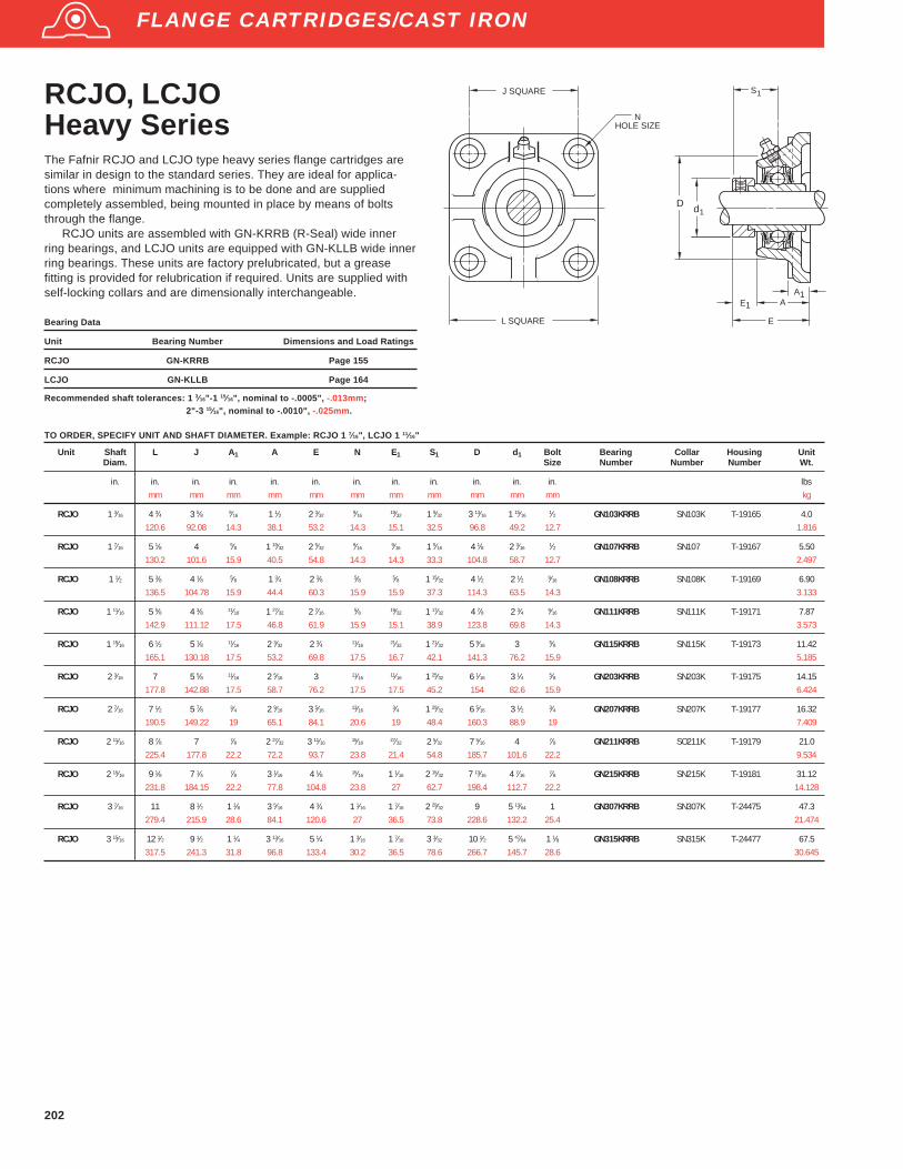
202
RCJO, LCJOHeavy SeriesThe Fafnir RCJO and LCJO type heavy series flange cartridges aresimilar in design to the standard series. They are ideal for applica-tions where minimum machining is to be done and are suppliedcompletely assembled, being mounted in place by means of boltsthrough the flange.
RCJO units are assembled with GN-KRRB (R-Seal) wide innerring bearings, and LCJO units are equipped with GN-KLLB wide innerring bearings. These units are factory prelubricated, but a greasefitting is provided for relubrication if required. Units are supplied withself-locking collars and are dimensionally interchangeable.
Bearing Data
Unit Bearing Number Dimensions and Load Ratings
RCJO GN-KRRB Page 155
LCJO GN-KLLB Page 164
Recommended shaft tolerances: 1 3⁄16"-1 15⁄16", nominal to -.0005", -.013mm;2"-3 15⁄16", nominal to -.0010", -.025mm.
J SQUARE
NHOLE SIZE
L SQUARE
A
E
dD
E A
1
1
S1
1
Unit Shaft L J A 1 A E N E1 S1 D d1 Bolt Bearing Collar Housing UnitDiam. Size Number Number Number Wt.
in. in. in. in. in. in. in. in. in. in. in. in. lbsmm mm mm mm mm mm mm mm mm mm mm kg
RCJO 1 3⁄16 4 3⁄4 3 5⁄8 9⁄16 1 1⁄2 2 3⁄329⁄16
19⁄32 1 9⁄32 3 13⁄16 1 15⁄161⁄2 GN103KRRB SN103K T-19165 4.0
120.6 92.08 14.3 38.1 53.2 14.3 15.1 32.5 96.8 49.2 12.7 1.816
RCJO 1 7⁄16 5 1⁄8 4 5⁄8 1 19⁄32 2 5⁄329⁄16
9⁄16 1 5⁄16 4 1⁄8 2 3⁄161⁄2 GN107KRRB SN107 T-19167 5.50
130.2 101.6 15.9 40.5 54.8 14.3 14.3 33.3 104.8 58.7 12.7 2.497
RCJO 1 1⁄2 5 3⁄8 4 1⁄8 5⁄8 1 3⁄4 2 3⁄8 5⁄8 5⁄8 1 15⁄32 4 1⁄2 2 1⁄2 9⁄16 GN108KRRB SN108K T-19169 6.90136.5 104.78 15.9 44.4 60.3 15.9 15.9 37.3 114.3 63.5 14.3 3.133
RCJO 1 11⁄16 5 5⁄8 4 3⁄8 11⁄16 1 27⁄32 2 7⁄16 5⁄8 19⁄32 1 17⁄32 4 7⁄8 2 3⁄4 9⁄16 GN111KRRB SN111K T-19171 7.87142.9 111.12 17.5 46.8 61.9 15.9 15.1 38.9 123.8 69.8 14.3 3.573
RCJO 1 15⁄16 6 1⁄2 5 1⁄8 11⁄16 2 3⁄32 2 3⁄4 11⁄16 21⁄32 1 21⁄32 5 9⁄16 3 5⁄8 GN115KRRB SN115K T-19173 11.42165.1 130.18 17.5 53.2 69.8 17.5 16.7 42.1 141.3 76.2 15.9 5.185
RCJO 2 3⁄16 7 5 5⁄8 11⁄16 2 5⁄16 3 11⁄16 11⁄16 1 25⁄32 6 1⁄16 3 1⁄4 5⁄8 GN203KRRB SN203K T-19175 14.15177.8 142.88 17.5 58.7 76.2 17.5 17.5 45.2 154 82.6 15.9 6.424
RCJO 2 7⁄16 7 1⁄2 5 7⁄8 3⁄4 2 9⁄16 3 5⁄16 13⁄16 3⁄4 1 29⁄32 6 5⁄16 3 1⁄2 3⁄4 GN207KRRB SN207K T-19177 16.32190.5 149.22 19 65.1 84.1 20.6 19 48.4 160.3 88.9 19 7.409
RCJO 2 11⁄16 8 7⁄8 7 7⁄8 2 27⁄32 3 11⁄16 15⁄16 27⁄32 2 5⁄32 7 5⁄16 4 7⁄8 GN211KRRB SO211K T-19179 21.0225.4 177.8 22.2 72.2 93.7 23.8 21.4 54.8 185.7 101.6 22.2 9.534
RCJO 2 15⁄16 9 1⁄8 7 1⁄4 7⁄8 3 1⁄16 4 1⁄8 15⁄16 1 1⁄16 2 15⁄32 7 13⁄16 4 7⁄16 7⁄8 GN215KRRB SN215K T-19181 31.12231.8 184.15 22.2 77.8 104.8 23.8 27 62.7 198.4 112.7 22.2 14.128
RCJO 3 7⁄16 11 8 1⁄2 1 1⁄8 3 5⁄16 4 3⁄4 1 1⁄16 1 7⁄16 2 29⁄32 9 5 13⁄64 1 GN307KRRB SN307K T-24475 47.3279.4 215.9 28.6 84.1 120.6 27 36.5 73.8 228.6 132.2 25.4 21.474
RCJO 3 15⁄16 12 1⁄2 9 1⁄2 1 1⁄4 3 13⁄16 5 1⁄4 1 3⁄16 1 7⁄16 3 3⁄32 10 1⁄2 5 47⁄64 1 1⁄8 GN315KRRB SN315K T-24477 67.5317.5 241.3 31.8 96.8 133.4 30.2 36.5 78.6 266.7 145.7 28.6 30.645
TO ORDER, SPECIFY UNIT AND SHAFT DIAMETER. Example: RCJO 1 7⁄16", LCJO 1 11⁄16"
FLANGE CARTRIDGES/CAST IRON
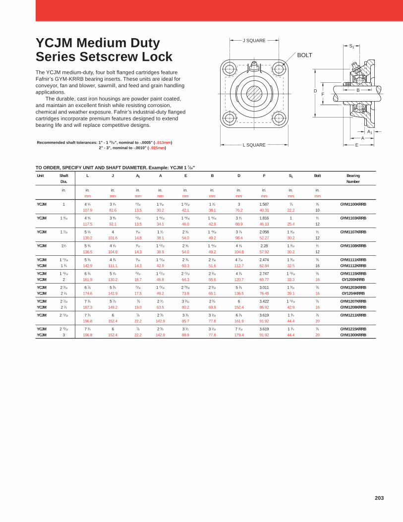
203
Unit Shaft L J A1 A E B D F S1 Bolt BearingDia. Number
in. in. in. in. in. in. in. in. in. in. in.mm mm mm mm mm mm mm mm mm mm
YCJM 1 4 1⁄4 3 1⁄4 17⁄32 1 3⁄16 1 21⁄32 1 1⁄2 3 1.587 7⁄8 3⁄8 GYM1100KRRB107.9 82.6 13.5 30.2 42.1 38.1 76.2 40.31 22.2 10
YCJM 1 3⁄16 4 5⁄8 3 5⁄8 17⁄32 1 11⁄32 1 13⁄16 1 11⁄16 3 1⁄2 1.816 1 1⁄2 GYM1103KRRB117.5 92.1 13.5 34.1 46.0 42.9 88.9 46.13 25.4 12
YCJM 1 7⁄16 5 1⁄8 4 9⁄16 1 1⁄2 2 1⁄8 1 15⁄16 3 7⁄8 2.058 1 3⁄16 1⁄2 GYM1107KRRB130.2 101.6 14.8 38.1 54.0 49.2 98.4 52.27 30.2 12
YCJM 11⁄2 5 3⁄8 4 1⁄8 9⁄16 1 17⁄32 2 1⁄8 1 15⁄16 4 1⁄8 2.28 1 3⁄16 1⁄2 GYM1108KRRB136.5 104.8 14.3 38.9 54.0 49.2 104.8 57.92 30.2 12
YCJM 1 11⁄16 5 5⁄8 4 3⁄8 9⁄16 1 11⁄16 2 3⁄8 2 1⁄32 4 7⁄16 2.474 1 9⁄325⁄8 GYM1111KRRB
YCJM 1 3⁄4 142.9 111.1 14.3 42.9 60.3 51.6 112.7 62.84 32.5 16 GYM1112KRRB
YCJM 1 15⁄16 6 3⁄8 5 1⁄8 21⁄32 1 27⁄32 2 17⁄32 2 3⁄16 4 3⁄4 2.747 1 15⁄165⁄8 GYM1115KRRB
YCJM 2 161.9 130.2 16.7 46.8 64.3 55.6 120.7 69.77 33.3 16 GY1200KRRB
YCJM 2 3⁄16 6 7⁄8 5 5⁄8 11⁄16 1 15⁄16 2 29⁄32 2 9⁄16 5 3⁄8 3.011 1 9⁄165⁄8 GYM1203KRRB
YCJM 2 1⁄4 174.6 142.9 17.5 49.2 73.8 65.1 136.5 76.48 39.1 16 GY1204KRRB
YCJM 2 7⁄16 7 3⁄8 5 7⁄8 3⁄4 2 1⁄2 3 5⁄32 2 3⁄4 6 3.422 1 11⁄165⁄8 GYM1207KRRB
YCJM 2 1⁄2 187.3 149.2 19.0 63.5 80.2 69.9 152.4 86.92 42.9 16 GYM1208KRRB
YCJM 2 11⁄16 7 3⁄4 6 7⁄8 2 5⁄8 3 3⁄8 3 1⁄16 6 3⁄8 3.619 1 3⁄4 3⁄4 GYM1211KRRB196.8 152.4 22.2 142.9 85.7 77.8 161.9 91.92 44.4 20
YCJM 2 15⁄16 7 3⁄4 6 7⁄8 2 5⁄8 3 1⁄2 3 1⁄16 7 1⁄16 3.619 1 3⁄4 3⁄4 GYM1215KRRBYCJM 3 196.8 152.4 22.2 142.9 88.9 77.8 179.4 91.92 44.4 20 GYM1300KRRB
TO ORDER, SPECIFY UNIT AND SHAFT DIAMETER. Example: YCJM 1 7⁄16"
Recommended shaft tolerances: 1" - 1 15⁄16", nominal to -.0005" ( -.013mm)2" - 3", nominal to -.0010" ( -.025mm)
YCJM Medium DutySeries Setscrew LockThe YCJM medium-duty, four bolt flanged cartridges featureFafnir’s GYM-KRRB bearing inserts. These units are ideal forconveyor, fan and blower, sawmill, and feed and grain handlingapplications.
The durable, cast iron housings are powder paint coated,and maintain an excellent finish while resisting corrosion,chemical and weather exposure. Fafnir’s industrial-duty flangedcartridges incorporate premium features designed to extendbearing life and will replace competitive designs.
J SQUARE
GBOLT SIZE
L SQUARE E
A
S1
F
A1
BD
BOLT

204
Unit Shaft H J L A E B A1 F S1 Bolt BearingDia. G Number
in. in. in. in. in. in. in. in. in. in. in.mm mm mm mm mm mm mm mm mm mm
YCJTM 1 5 9⁄16 4 19⁄32 3 1⁄8 1 1⁄4 1 21⁄32 1 1⁄2 17⁄32 1.587 7⁄8 3⁄8 GYM1100KRRB141.3 116.7 79.5 31.8 42.1 38.1 13.5 40.31 22.2 10
YCJTM 1 3⁄16 6 1⁄8 5 1⁄8 3 5⁄8 1 11⁄32 1 13⁄16 1 11⁄1615⁄32 1.816 1 1⁄2 GYM1103KRRB
155.6 130.2 92.1 34.1 46.0 42.9 11.9 46.13 25.4 12
YCJTM 1 7⁄16 6 3⁄4 5 21⁄32 4 1⁄8 1 1⁄2 2 1⁄8 1 15⁄161⁄2 2.058 1 3⁄16
1⁄2 GYM1107KRRB171.5 143.7 104.8 38.1 54.0 49.2 12.7 52.27 30.2 12
YCJTM 1 1⁄2 7 1⁄16 5 27⁄32 4 3⁄8 1 17⁄32 2 1⁄8 1 15⁄161⁄2 2.28 1 3⁄16
1⁄2 GYM1108KRRB179.4 148.4 111.1 38.9 54.0 49.2 12.7 57.92 30.2 12
YCJTM 1 11⁄16 7 7⁄16 6 3⁄16 4 9⁄16 1 11⁄16 2 3⁄8 2 1⁄32 1⁄2 2.474 1 9⁄32 5⁄8 GYM1111KRRBYCJTM 1 3⁄4 188.9 157.2 115.9 42.9 60.3 51.6 12.7 62.84 32.5 16 GYM1112KRRB
YCJTM 1 15⁄16 8 1⁄2 7 1⁄4 5 1 27⁄32 2 17⁄32 2 3⁄16 21⁄32 2.747 1 15⁄16 5⁄8 GYM1115KRRBYCJTM 2 215.9 184.2 127.0 46.8 64.3 55.6 16.7 69.77 33.3 16 GY1200KRRB
TO ORDER, SPECIFY UNIT AND SHAFT DIAMETER. Example: YCJM 1 7⁄16"
Recommended shaft tolerances: 1" - 1 15⁄16", nominal to -.0005" ( -.013mm)2" - 3", nominal to -.0010" ( -.025mm)
YCJTM Medium DutySeries Setscrew LockThe YCJTM medium-duty, two-bolt flanged cartridges featureFafnir’s GYM-KRRB bearing inserts. These units are ideal forconveyor, fan and blower, sawmill, and feed and grain handlingapplications.
The durable, cast iron housings are powder paint coated,and maintain an excellent finish while resisting corrosion,chemical and weather exposure. Fafnir’s industrial-duty flangedcartridges units incorporate premium features designed toextend bearing life and will replace competitive designs.
EA
A1
BF
S1GBOLT SIZE
L
H J

205
Bearing Data
Unit Bearing Number Dimensions and Load Ratings
RCJT G-KRRB Page 154
TCJT G-KPPB Page 165
LCJT G-KLLB Page 162
NHOLE SIZE
L
H J
A
E
d
A1
1
Unit Shaft H J L A N E A 1 d1 Bearing Collar Housing UnitDiam. Number Number Number Wt.
in. in. in. in. in. in. in. in. in. new lbsmm mm mm mm mm mm mm mm mm RCJT TCJT (old) kg
RCJT 1⁄2 G1008KRRB — S1008KRCJT 5⁄8 3 7⁄8 3 2 1⁄8 31⁄32 27⁄64 1 37⁄64 13⁄32 1 1⁄8 G1010KRRB — S1010K T-40219 1.30RCJT 11⁄16 98.4 76.2 54.0 24.6 10.7 40.1 10.3 28.6 G1011KRRB — S1011K 0.590RCJT 17 GE17KRRB — SE17K
RCJT 3⁄4 4 13⁄32 3 17⁄32 2 3⁄8 1 3⁄3227⁄64 1 51⁄64
7⁄16 1 5⁄16 G1012KRRB — S1012K T-40220 1.30RCJT 20 111.9 89.7 60.5 27.8 10.7 45.6 11.1 33.3 GE20KRRB — SE20K 0.590
RCJT,TCJT 13⁄16 G1013KRRB G1013KPPB3 S1013KRCJT,TCJT 7⁄8 4 7⁄8 3 29⁄32 2 3⁄4 1 1⁄8 29⁄64 1 25⁄32
7⁄16 1 1⁄2 G1014KRRB G1014KPPB3 S1014K T-40221 1.73RCJT,TCJT 15⁄16 123.8 99.2 69.8 28.6 11.5 45.2 11.1 38.1 G1015KRRB G1015KPPB3 S1015K (T-21412P) 0.785RCJT,TCJT 1 G1100KRRB G1100KPPB3 S1100KRCJT,TCJT 25 GE25KRRB GE25KPPB3 SE25K
RCJT,TCJT 1 1⁄16 G1101KRRB G1101KPPB3 S1101KRCJT,TCJT 1 1⁄8 5 9⁄16 4 19⁄32 3 1⁄8 1 1⁄4 29⁄64 1 31⁄32
15⁄32 1 47⁄64 G1102KRRB G1102KPPB3 S1102K T-40222 2.40RCJT,TCJT 1 3⁄16 141.3 116.7 79.4 31.8 11.5 50 11.9 44.1 G1103KRRB G1103KPPB3 S1103K (T-21548P) 1.09TCJT 1 1⁄4S — G1103KPPB4 S1103K3RCJT,TCJT 30 GE30KRRB GE30KPPB3 SE30K
RCJT,TCJT 1 1⁄4 G1104KRRB G1104KPPB2 S1104K(1)
RCJT,TCJT 1 5⁄16 6 1⁄8 5 1⁄8 3 5⁄8 1 11⁄3233⁄64 2 3⁄32
15⁄32 2 1⁄8 G1105KRRB G1105KPPB2 S1105K(1)
T-40223 3.18RCJT,TCJT 1 3⁄8 155.6 130.2 92.1 34.1 13.1 53.2 11.9 54 G1106KRRB G1106KPPB2 S1106K
(1)(T-21414) 1.444
RCJT,TCJT 1 7⁄16 G1107KRRB G1107KPPB2 S1107K(1)
RCJT,TCJT 35 GE35KRRB GE35KPPB2 SE35K
RCJT,TCJT 1 1⁄2 6 3⁄4 5 21⁄32 4 1⁄8 1 1⁄2 33⁄64 2 5⁄161⁄2 2 3⁄8 G1108KRRB G1108KPPB3 S1108KT T-40224 4.83
RCJT,TCJT 1 9⁄16 171.4 143.6 104.7 38.1 13.1 58.7 12.7 60.3 — G1109KPPB3 S1109KT (T-22529) 2.193RCJT,TCJT 40 GE40KRRB GE40KPPB3 SE40K
RCJT,TCJT 1 5⁄8 G1110KRRB G1110KPPB4 S1110KRCJT,TCJT 1 11⁄16 7 1⁄16 5 53⁄64 4 3⁄8 1 17⁄32
33⁄64 2 5⁄161⁄2 2 1⁄2 G1111KRRB G1111KPPB4 S1111K T-40225 5.24
RCJT,TCJT 1 3⁄4 179.4 148 111.1 38.9 13.1 58.7 12.7 63.5 G1112KRRB G1112KPPB4 S1112K (T-21416) 2.379RCJT,TCJT 45 GE45KRRB GE45KPPB4 SE45K
RCJT,TCJT 1 7⁄8 7 7⁄16 6 3⁄16 4 9⁄16 1 11⁄1643⁄64 2 19⁄32
1⁄2 2 3⁄4 G1114KRRB G1114KPPB3 S1114K T-40226 6RCJT,TCJT 1 15⁄16 188.9 157.2 115.9 42.9 17.1 65.7 12.7 69.9 G1115KRRB G1115KPPB3 S1115K (T-21418) 2.724RCJT,TCJT 50 GE50KRRB GE50KPPB3 SE50K
RCJT,TCJT 2 G1200KRRB G1200KPPB4 S1200KRCJT,TCJT 2 1⁄8 8 1⁄2 7 1⁄4 5 1 27⁄32
43⁄64 2 15⁄1621⁄32 3 G1202KRRB G1202KPPB4 S1202K T-40227 8.08
RCJT,TCJT 2 3⁄16 215.9 184.1 127 46.8 17.1 74.6 16.7 76.2 G1203KRRB G1203KPPB4 S1203K (T-23788) 3.668RCJT,TCJT 55 GE55KRRB GE55KPPB4 SE55K
TO ORDER, SPECIFY UNIT AND SHAFT DIAMETER. Example: RCJT 1 3⁄16",TCJT 1 3⁄16 ; POPULAR SIZES IN BOLD.
Fafnir RCJT, TCJT, and LCJT flange cartridges are basically the samedesign as the RCJ, TCJ, and LCJ types except they have two bolt holesinstead of four. They are designed chiefly to fill the need for applicationswhere the mounting area is restricted.
The RCJT flange cartridge is equipped with G-KRRB (R-Seal) wideinner ring bearings, the TCJT with G-KPPB (Tri-Ply Seal) wide inner ringbearings, and the LCJT with the G-KLLB (Mechani-Seal) wide inner ringbearings.
These units are factory prelubricated, but a grease fitting isprovided for relubrication if required. All units are supplied with self-locking collars.
Contact The Torrington Company to discuss highly corrosiveapplications (i.e. food processing, chemical exposure) where FafnirTDC® bearings can be utilized.
Recommended shaft tolerances: 1⁄2"-1 15⁄16", nominal to -.0005", -.013mm;2"-2 3/16", nominal to -.0010", -.025mm.
RCJT, TCJT, LCJTIndustrial Series
FLANGE CARTRIDGES/CAST IRON
(1) Add C1 suffix to collar numbers for G...KPPB2 bearings (TCJT).

206
RCJTC Industrial SeriesConcentric CollarThe Fafnir RCJTC flange cartridges are basically the same design asthe RCJT series except they use the concentric collar rather than theself-locking eccentric collar as the shaft locking device. All RCJTCunits are equipped with GC-KRRB wide inner ring, concentric collarbearings. The spherical outside diameter of these bearings mountedin corresponding machined housing seats provides the initial self-alignment. Bolt hole spacing dimensions are interchangeable withmost competitive units as well as the Fafnir RCJT series.
These units are factory prelubricated, but a grease fitting is pro-vided for relubrication if required. All units are supplied with concen-tric collars.
Bearing Data
Unit Bearing Number Dimensions and Load Ratings
RCJTC GC-KRRB Page 166
Recommended shaft tolerances: 1⁄2"-1 15⁄16", nominal to -.0005", -.013mmAll units have 1⁄4- 28 grease fittings.
NHOLE SIZE
L
H J
S1
A
E
d1
A1
Unit Shaft H J L A E N A 1 d1 S1 Bearing Collar Housing UnitDiam. Number Number Number Wt.
in. in. in. in. in. in. in. in. in. in. new lbsmm mm mm mm mm mm mm mm mm mm (old) kg
RCJTC 5⁄8 3 7⁄8 3 2 3⁄8 1 3⁄32 1 3⁄32 25⁄64 21⁄64 1 11⁄32 39⁄64 GC1010KRRB C203 T-27181 0.8198.4 76.2 60.3 27.8 32.1 9.9 8.3 34.1 15.5 0.368
RCJTC 3⁄4 4 13⁄32 3 17⁄32 2 3⁄8 31⁄32 1 9⁄32 25⁄64 7⁄16 1 1⁄2 47⁄64 GC1012KRRB C204 T-27183 1.2111.9 89.7 60.3 24.6 32.5 9.9 11.1 38.1 18.7 0.545
RCJTC 1 4 7⁄8 3 57⁄64 2 3⁄4 1 1⁄32 1 7⁄16 15⁄32 17⁄32 1 3⁄4 51⁄64 GC1100KRRB C205 T-27200 1.58123.8 98.81 69.8 26.2 36.5 11.9 13.5 44.4 20.2 0.717
RCJTC 1 1⁄8 5 9⁄16 4 19⁄32 3 3⁄16 1 1⁄8 1 9⁄16 29⁄64 17⁄32 2 1⁄16 57⁄64 GC1102KRRB C206 T-27197 2.28RCJTC 1 3⁄16 141.3 116.7 81 28.6 39.7 11.5 13.5 52.4 22.6 GC1103KRRB 1.035RCJTC 1 1⁄4S GC1103KRRB3
RCJTC 1 1⁄4 6 1⁄8 5 1⁄8 3 5⁄8 1 11⁄32 1 3⁄4 33⁄64 9⁄16 2 11⁄32 1 GC1104KRRB C207 T-27263 3.30RCJTC 1 3⁄8 155.6 130.2 92.1 34.1 44.4 13.1 14.3 59.5 25.4 GC1106KRRB 1.498RCJTC 1 7⁄16 GC1107KRRB
RCJTC 1 11⁄16 7 1⁄16 5 27⁄32 4 3⁄8 1 27⁄64 2 3⁄64 33⁄64 9⁄16 2 7⁄8 1 5⁄32 GC1111KRRB C209 T-28537 4.62179.4 148.4 111.1 36.1 52 13.1 14.3 73 29.4 2.097
RCJTC 1 15⁄16 7 7⁄16 6 3⁄16 4 9⁄16 1 9⁄16 2 5⁄32 43⁄64 9⁄16 3 1⁄8 1 3⁄16 GC1115KRRB C210 T-27286 5.50188.9 157.2 115.9 39.7 54.8 17.1 14.3 79.4 30.2 2.497
TO ORDER, SPECIFY UNIT AND SHAFT DIAMETER. Example: RCJTC 1 3/16"
FLANGE CARTRIDGES/CAST IRON

207
VCJT Standard SeriesThe Fafnir VCJT flange cartridges are basically the same in design andoutstanding features as the VCJ types except that they have two boltholes instead of four. This allows for mounting in restricted areas. Theunits are assembled with GRA-RRB bearings with positive contact land-riding seals, and self locking collars. These units are factoryprelubricated, but a grease fitting is provided for relubrication if required.
Bearing Data
Unit Bearing Number Dimensions and Load Ratings
VCJT GRA-RRB Page 157
Recommended shaft tolerances: 1⁄2"-1 15⁄16", nominal to -.0005", -.013mm;
2"-2 3⁄16", nominal to -.0010", -.025mm.
NHOLE SIZE
L
H J
A
E
dB1
A
S
1
1
1
TO ORDER, SPECIFY UNIT AND SHAFT DIAMETER. Example: VCJT 1"; POPULAR SIZES IN BOLD.
Unit Shaft H J L A E N B 1 A1 d1 S1 Bearing Collar Housing UnitDiam. Number Number Number Wt.
in. in. in. in. in. in. in. in. in. in. in. new lbsmm mm mm mm mm mm mm mm mm mm mm (old) kg
VCJT 1⁄2 3 7⁄8 3 2 1⁄8 31⁄32 1 17⁄3227⁄64 1 1⁄8 13⁄32 1 7⁄64
7⁄8 GRA008RRB S1008K T-22244P 1.3VCJT 5⁄8 98.4 76.2 53.9 24.6 38.9 10.7 28.6 10.3 28.2 22.2 GRA010RRB S1010K 0.59VCJT 17 GRAE17RRB SE17K
VCJT 3⁄4 4 13⁄32 3 17⁄32 2 3⁄8 1 3⁄32 1 43⁄64 25⁄64 1 7⁄32 7⁄16 1 19⁄64 59⁄64 GRA012RRB S1012K T-21409P 1.44VCJT 20 111.9 89.7 60.3 27.8 42.5 9.9 31 11.1 32.9 23.4 GRAE20RRB SE20K 0.518
VCJT 7⁄8 GRA014RRB S1014KVCJT 15⁄16 4 7⁄8 3 29⁄32 2 3⁄4 1 1⁄8 1 43⁄64 29⁄64 1 7⁄32 7⁄16 1 31⁄64 59⁄64 GRA015RRB S1015K T-21412P 1.63VCJT 1 123.8 99.2 69.8 28.6 42.5 11.5 31 11.1 37.7 23.4 GRA100RRB S1100K 0.74VCJT 25 GRAE25RRB SE25K
VCJT 1 1⁄8 GRA102RRB S1102KVCJT 1 3⁄16 5 9⁄16 4 19⁄32 3 1⁄8 1 3⁄16 1 53⁄64 29⁄64 1 13⁄32 15⁄32 1 47⁄64 1 1⁄16 GRA103RRB S1103K T-21548P 2.26VCJT 1 1⁄4S 141.3 116.7 79.4 30.2 46.4 11.5 35.7 11.9 44.1 27 GRA103RRB2 S1103K3 1.026VCJT 30 GRAE30RRB SE30K
VCJT 1 1⁄4 GRA104RRB S1104K T-40223 3VCJT 1 3⁄8 6 1⁄8 5 1⁄8 3 5⁄8 1 11⁄32 1 31⁄32 33⁄64 1 17⁄32 15⁄32 2 1⁄8 1 5⁄32 GRA106RRB S1106KVCJT 1 7⁄16 155.6 130.2 92.1 34.1 50 13.1 38.9 11.9 54 29.4 GRA107RRB S1107K (T-21414) 1.362VCJT 35 GRAE35RRB SE35K
VCJT 1 1⁄2 6 3⁄4 5 21⁄32 4 1⁄8 1 1⁄2 2 7⁄32 33⁄64 1 23⁄32 1⁄2 2 23⁄64 1 9⁄32 GRA108RRB S1108KT T-40224 4.57VCJT 40 171.4 143.6 104.7 38.1 56.4 13.1 43.7 12.7 59.9 32.5 GRAE40RRB SE40K (T-22529) 2.075
VCJT 1 5⁄8 GRA110RRB S1110KVCJT 1 11⁄16 7 1⁄16 5 53⁄64 4 3⁄8 1 17⁄32 2 7⁄32 33⁄64 1 23⁄32 1⁄2 2 31⁄64 1 9⁄32 GRA111RRB S1111K T-40225 4.91VCJT 1 3⁄4 179.4 148.0 111.1 38.9 56.4 13.1 43.7 12.7 63.1 32.5 GRA112RRB S1112K (T-21416) 2.229VCJT 45 GRAE45RRB SE45K
VCJT 1 7⁄8 GRA114RRB S1114KVCJT 1 15⁄16 7 7⁄16 6 3⁄16 4 9⁄16 1 11⁄16 2 3⁄8 43⁄64 1 23⁄32 1⁄2 2 47⁄64 1 9⁄32 GRA115RRB S1115K T-40226 5.49VCJT 2S 188.9 157.2 115.8 42.9 60.3 17.1 43.7 12.7 69.5 32.5 GRA115RRB2 S1115K2 (T-21418) 2.492VCJT 50 GRAE50RRB SE50K
VCJT 2 8 1⁄2 7 1⁄4 5 1 27⁄32 2 21⁄32 43⁄64 1 29⁄32 21⁄32 2 63⁄64 1 7⁄16 GRA200RRB S1200K T-40227 6.81VCJT 2 3⁄16 215.9 184.1 127 46.8 67.4 17.1 48.4 16.7 75.8 36.5 GRA203RRB S1203K (T-23788) 3.092VCJT 55 GRAE55RRB SE55K
FLANGE CARTRIDGES/CAST IRON
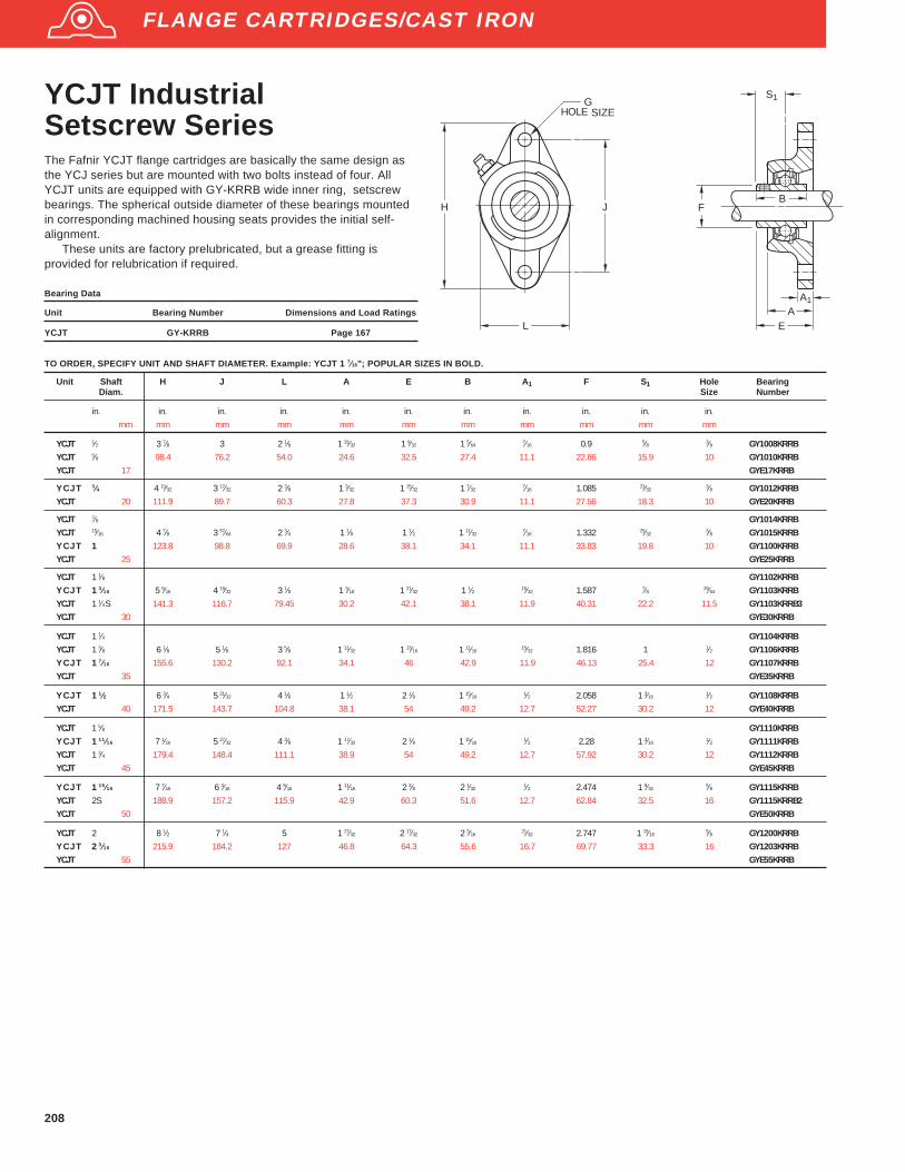
208
YCJT IndustrialSetscrew SeriesThe Fafnir YCJT flange cartridges are basically the same design asthe YCJ series but are mounted with two bolts instead of four. AllYCJT units are equipped with GY-KRRB wide inner ring, setscrewbearings. The spherical outside diameter of these bearings mountedin corresponding machined housing seats provides the initial self-alignment.
These units are factory prelubricated, but a grease fitting isprovided for relubrication if required.
Bearing Data
Unit Bearing Number Dimensions and Load Ratings
YCJT GY-KRRB Page 167
Unit Shaft H J L A E B A 1 F S1 Hole BearingDiam. Size Number
in. in. in. in. in. in. in. in. in. in. in.mm mm mm mm mm mm mm mm mm mm mm
YCJT 1⁄2 3 7⁄8 3 2 1⁄8 1 31⁄32 1 9⁄32 1 5⁄647⁄16 0.9 5⁄8 3⁄8 GY1008KRRB
YCJT 5⁄8 98.4 76.2 54.0 24.6 32.5 27.4 11.1 22.86 15.9 10 GY1010KRRBYCJT 17 GYE17KRRB
YCJT 3⁄4 4 13⁄32 3 17⁄32 2 3⁄8 1 3⁄32 1 15⁄32 1 7⁄327⁄16 1.085 23⁄32
3⁄8 GY1012KRRBYCJT 20 111.9 89.7 60.3 27.8 37.3 30.9 11.1 27.56 18.3 10 GYE20KRRB
YCJT 7⁄8 GY1014KRRBYCJT 15⁄16 4 7⁄8 3 57⁄64 2 3⁄4 1 1⁄8 1 1⁄2 1 11⁄32
7⁄16 1.332 25⁄323⁄8 GY1015KRRB
YCJT 1 123.8 98.8 69.9 28.6 38.1 34.1 11.1 33.83 19.8 10 GY1100KRRBYCJT 25 GYE25KRRB
YCJT 1 1⁄8 GY1102KRRBYCJT 13⁄16 5 9⁄16 4 19⁄32 3 1⁄8 1 3⁄16 1 21⁄32 1 1⁄2 15⁄32 1.587 7⁄8 29⁄64 GY1103KRRBYCJT 1 1⁄4S 141.3 116.7 79.45 30.2 42.1 38.1 11.9 40.31 22.2 11.5 GY1103KRRB3YCJT 30 GYE30KRRB
YCJT 1 1⁄4 GY1104KRRBYCJT 1 3⁄8 6 1⁄8 5 1⁄8 3 5⁄8 1 11⁄32 1 13⁄16 1 11⁄16
15⁄32 1.816 1 1⁄2 GY1106KRRBYCJT 17⁄16 155.6 130.2 92.1 34.1 46 42.9 11.9 46.13 25.4 12 GY1107KRRBYCJT 35 GYE35KRRB
YCJT 11⁄2 6 3⁄4 5 21⁄32 4 1⁄8 1 1⁄2 2 1⁄8 1 15⁄161⁄2 2.058 1 3⁄16
1⁄2 GY1108KRRBYCJT 40 171.5 143.7 104.8 38.1 54 49.2 12.7 52.27 30.2 12 GYE40KRRB
YCJT 1 5⁄8 GY1110KRRBYCJT 111⁄16 7 1⁄16 5 27⁄32 4 3⁄8 1 17⁄32 2 1⁄8 1 15⁄16
1⁄2 2.28 1 3⁄161⁄2 GY1111KRRB
YCJT 1 3⁄4 179.4 148.4 111.1 38.9 54 49.2 12.7 57.92 30.2 12 GY1112KRRBYCJT 45 GYE45KRRB
YCJT 115⁄16 7 7⁄16 6 3⁄16 4 9⁄16 1 11⁄16 2 3⁄8 2 1⁄321⁄2 2.474 1 9⁄32
5⁄8 GY1115KRRBYCJT 2S 188.9 157.2 115.9 42.9 60.3 51.6 12.7 62.84 32.5 16 GY1115KRRB2YCJT 50 GYE50KRRB
YCJT 2 8 1⁄2 7 1⁄4 5 1 27⁄32 2 17⁄32 2 3⁄1621⁄32 2.747 1 15⁄16
5⁄8 GY1200KRRBYCJT 23⁄16 215.9 184.2 127 46.8 64.3 55.6 16.7 69.77 33.3 16 GY1203KRRBYCJT 55 GYE55KRRB
TO ORDER, SPECIFY UNIT AND SHAFT DIAMETER. Example: YCJT 1 7⁄16"; POPULAR SIZES IN BOLD.
EA
A1
BF
S1GBOLT SIZE
L
H J
FLANGE CARTRIDGES/CAST IRON
HOLE
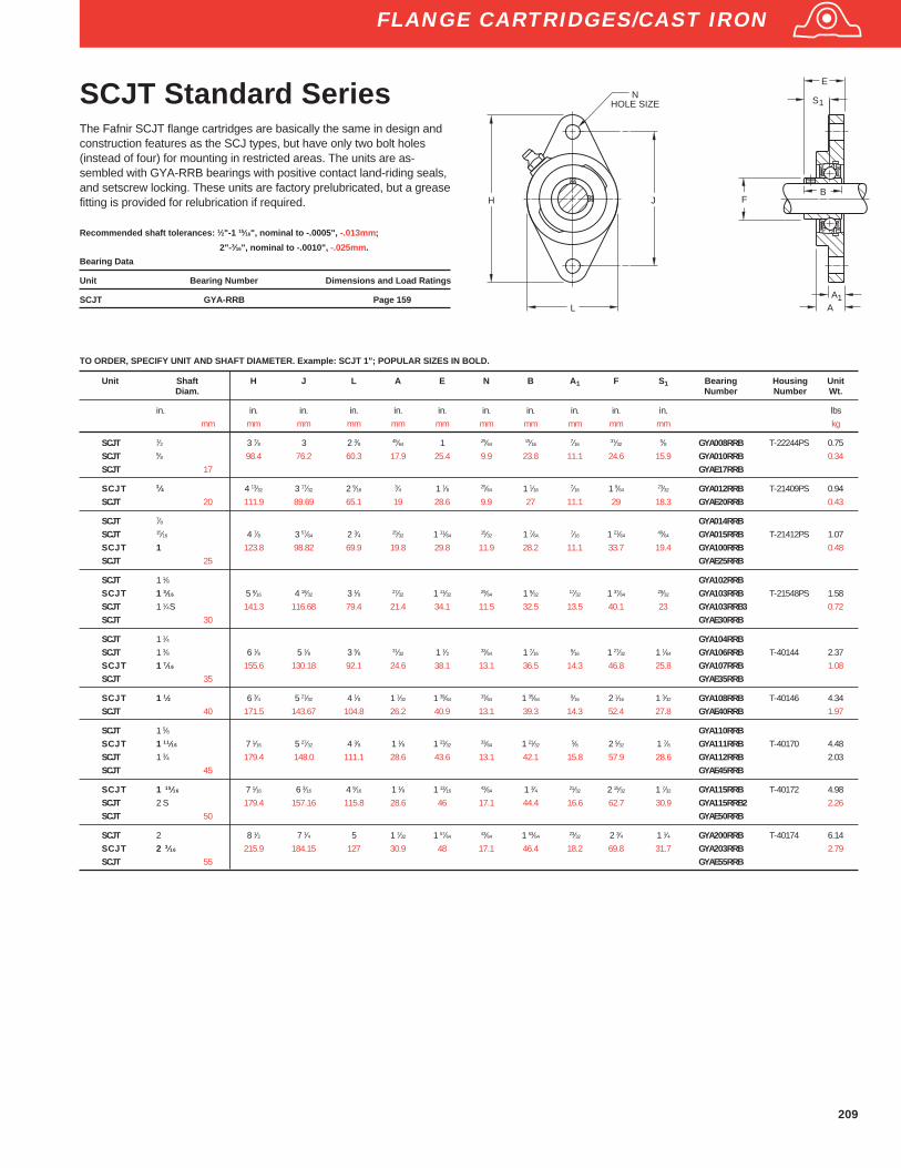
209
SCJT Standard SeriesThe Fafnir SCJT flange cartridges are basically the same in design andconstruction features as the SCJ types, but have only two bolt holes(instead of four) for mounting in restricted areas. The units are as-sembled with GYA-RRB bearings with positive contact land-riding seals,and setscrew locking. These units are factory prelubricated, but a greasefitting is provided for relubrication if required.
Recommended shaft tolerances: 1⁄2"-1 15⁄16", nominal to -.0005", -.013mm;
2"- 3⁄16", nominal to -.0010", -.025mm.
Bearing Data
Unit Bearing Number Dimensions and Load Ratings
SCJT GYA-RRB Page 159
NHOLE SIZE
L
H J FB
S
AA
E
1
1
Unit Shaft H J L A E N B A 1 F S1 Bearing Housing UnitDiam. Number Number Wt.
in. in. in. in. in. in. in. in. in. in. in. lbsmm mm mm mm mm mm mm mm mm mm mm kg
SCJT 1⁄2 3 7⁄8 3 2 3⁄8 45⁄64 1 25⁄6415⁄16
7⁄1631⁄32
5⁄8 GYA008RRB T-22244PS 0.75SCJT 5⁄8 98.4 76.2 60.3 17.9 25.4 9.9 23.8 11.1 24.6 15.9 GYA010RRB 0.34SCJT 17 GYAE17RRB
SCJT 3⁄4 4 13⁄32 3 17⁄32 2 9⁄163⁄4 1 1⁄8 25⁄64 1 1⁄16
7⁄16 1 9⁄6423⁄32 GYA012RRB T-21409PS 0.94
SCJT 20 111.9 89.69 65.1 19 28.6 9.9 27 11.1 29 18.3 GYAE20RRB 0.43
SCJT 7⁄8 GYA014RRBSCJT 15⁄16 4 7⁄8 3 57⁄64 2 3⁄4 25⁄32 1 11⁄64
15⁄32 1 7⁄647⁄16 1 21⁄64
49⁄64 GYA015RRB T-21412PS 1.07SCJT 1 123.8 98.82 69.9 19.8 29.8 11.9 28.2 11.1 33.7 19.4 GYA100RRB 0.48SCJT 25 GYAE25RRB
SCJT 1 1⁄8 GYA102RRBSCJT 1 3⁄16 5 9⁄16 4 19⁄32 3 1⁄8 27⁄32 1 11⁄32 29⁄64 1 9⁄32 17⁄32 1 37⁄64 29⁄32 GYA103RRB T-21548PS 1.58SCJT 1 1⁄4S 141.3 116.68 79.4 21.4 34.1 11.5 32.5 13.5 40.1 23 GYA103RRB3 0.72SCJT 30 GYAE30RRB
SCJT 1 1⁄4 GYA104RRBSCJT 1 3⁄8 6 1⁄8 5 1⁄8 3 5⁄8 31⁄32 1 1⁄2 33⁄64 1 7⁄16 9⁄16 1 27⁄32 1 1⁄64 GYA106RRB T-40144 2.37SCJT 1 7⁄16 155.6 130.18 92.1 24.6 38.1 13.1 36.5 14.3 46.8 25.8 GYA107RRB 1.08SCJT 35 GYAE35RRB
SCJT 1 1⁄2 6 3⁄4 5 21⁄32 4 1⁄8 1 1⁄32 1 39⁄64 33⁄64 1 35⁄64 9⁄16 2 1⁄16 1 3⁄32 GYA108RRB T-40146 4.34SCJT 40 171.5 143.67 104.8 26.2 40.9 13.1 39.3 14.3 52.4 27.8 GYAE40RRB 1.97
SCJT 1 5⁄8 GYA110RRBSCJT 1 11⁄16 7 1⁄16 5 27⁄32 4 3⁄8 1 1⁄8 1 23⁄32 33⁄64 1 21⁄32 5⁄8 2 5⁄32 1 7⁄8 GYA111RRB T-40170 4.48SCJT 1 3⁄4 179.4 148.0 111.1 28.6 43.6 13.1 42.1 15.8 57.9 28.6 GYA112RRB 2.03SCJT 45 GYAE45RRB
SCJT 1 15⁄16 7 1⁄16 6 3⁄16 4 9⁄16 1 1⁄8 1 13⁄16 43⁄64 1 3⁄4 21⁄32 2 15⁄32 1 7⁄32 GYA115RRB T-40172 4.98SCJT 2 S 179.4 157.16 115.8 28.6 46 17.1 44.4 16.6 62.7 30.9 GYA115RRB2 2.26SCJT 50 GYAE50RRB
SCJT 2 8 1⁄2 7 1⁄4 5 1 7⁄32 1 57⁄64 43⁄64 1 53⁄64 23⁄32 2 3⁄4 1 1⁄4 GYA200RRB T-40174 6.14SCJT 2 3⁄16 215.9 184.15 127 30.9 48 17.1 46.4 18.2 69.8 31.7 GYA203RRB 2.79SCJT 55 GYAE55RRB
TO ORDER, SPECIFY UNIT AND SHAFT DIAMETER. Example: SCJT 1"; POPULAR SIZES IN BOLD.
FLANGE CARTRIDGES/CAST IRON
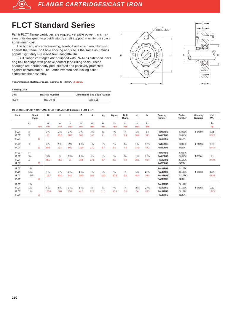
210
FLCT Standard SeriesFafnir FLCT flange cartridges are rugged, versatile power transmis-sion units designed to provide sturdy shaft support in minimum spaceat minimum cost.
The housing is a space-saving, two-bolt unit which mounts flushagainst the frame. Bolt hole spacing and size is the same as Fafnir’spopular light duty Pressed-Steel Flangette Unit.
FLCT flange cartridges are equipped with RA-RRB extended innerring ball bearings with positive contact land-riding seals. Thesebearings are permanently prelubricated and positively protectedagainst contaminates. The Fafnir invented self-locking collarcompletes the assembly.
Recommended shaft tolerances: nominal to -.0005", -.013mm.
Bearing Data
Unit Bearing Number Dimensions and Load Ratings
FLCT RA...RRB Page 156
Unit Shaft H J L E A A 3 N1 sq. Bolt d 1 M Bearing Collar Housing UnitDiam. Diam. Number Number Number Wt.
in. in. in. in. in. in. in. in. in. in. in. lbsmm mm mm mm mm mm mm mm mm mm mm kg
FLCT 1⁄2 3 3⁄16 2 1⁄2 2 5⁄16 1 3⁄16 37⁄64 9⁄32 9⁄32 1⁄4 1 1⁄8 1 1⁄2 RA008RRB S1008K T-24080 0.71FLCT 5⁄8 81 63.5 58.7 30.2 14.7 7.1 7.1 6.4 28.6 38.1 RA010RRB S1010K 0.322FLCT 17 RAE17RRB SE17K
FLCT 3⁄4 3 9⁄16 2 13⁄16 2 5⁄8 1 19⁄64 43⁄64 11⁄32 11⁄32 5⁄16 1 5⁄16 1 25⁄32 RA012RRB S1012K T-24093 0.98FLCT 20 90.5 71.4 66.7 32.9 17.1 8.7 8.7 7.9 33.3 45.2 RAE20RRB SE20K 0.445
FFLCT 7⁄8 RA014RRB S1014KFLCT 15⁄16 3 3⁄4 3 2 51⁄64 1 23⁄64 11⁄16 11⁄32 11⁄32 5⁄16 1 1⁄2 1 63⁄64 RA015RRB S1015K T-23961 1.1FLCT 1 95.2 76.2 71 34.5 17.5 8.7 8.7 7.9 38.1 50.4 RA100RRB S1100K 0.499FLCT 25 RAE25RRB SE25K
FLCT 1 1⁄8 RA102RRB S1102KFLCT 1 3⁄16 4 7⁄16 3 9⁄16 3 5⁄16 1 33⁄64 13⁄16 13⁄32 13⁄32 3⁄8 1 3⁄4 2 11⁄32 RA103RRB S1103K T-24018 1.84FLCT 1 1⁄4S 112.7 90.5 84.1 38.5 20.6 10.3 10.3 9.5 44.4 59.5 RA103RRB2 S1103K3 0.835FLCT 30 RAE30RRB SE30K
FLCT 1 1⁄4 RA104RRB S1104KFLCT 1 3⁄8 4 15⁄16 3 15⁄16 3 11⁄16 1 21⁄32 7⁄8 7⁄16 13⁄32 3⁄8 2 1⁄8 2 47⁄64 RA106RRB S1106K T-24068 2.37FLCT 1 7⁄16 125.4 100 93.7 41.1 22.2 11.1 10.3 9.5 54 69.5 RA107RRB S1107K 1.075FLCT 35 RAE35RRB SE35K
TO ORDER, SPECIFY UNIT AND SHAFT DIAMETER. Example: FLCT 1 3⁄16"
FL
CT
FA
FN
IR
NHOLE SIZE
L
H J
A
M
E
NN1
A3
d1
FLANGE CARTRIDGES/CAST IRON

211
RFC Industrial PilotedSeries Concentric CollarThe Fafnir RFC piloted flange cartridges assure accurate mountingfits and better support for heavy loads.The cast iron units areparticularly suited for applications in material handling, industrialconveyor equipment, and farm and construction equipment.
The RFC units are assembled with R-Seal (GC-KRRB) wide innerring bearings with a concentric locking collar. These units are factoryprelubricated, but a grease fitting is provided for relubrication ifrequired.
Bearing Data
Unit Bearing Number Dimensions and Load Ratings
RFC GC-KRRB Page 166
Recommended shaft tolerances: 1⁄2"-1 15⁄16", nominal to -.0005", -.013mm;
2"-2 3⁄16", nominal to -.0010", -.025mm.
TO ORDER, SPECIFY UNIT AND SHAFT DIAMETER. Example: RFC 1 7⁄16"
Unit Shaft D J H S 1 K N G A E1 A3 E A1 d1 Bearing Collar Housing UnitDiam. Number Number Number Wt.
in. in. in. in. in. in. in. in. in. in. in. in. in. in. lbsmm mm mm mm mm mm mm mm mm mm mm mm mm mm kg
RFC 1 3 3 5⁄8 4 3⁄8 51⁄64 9⁄64 13⁄32 1 31⁄64 1 7⁄64 3⁄8 1⁄4 1 15⁄64 3⁄8 1 3⁄4 GC1015KRRB C205 T-27031 2.5476.2 92.1 111.1 20.2 3.6 10.3 37.7 28.2 9.5 6.4 31.4 9.5 44.4 1.152
RFC 1 1⁄8 3.375 4 1⁄8 5 57⁄64 9⁄64 15⁄32 1 39⁄64 1 13⁄64 13⁄32 27⁄64 1 3⁄16 3⁄8 2 1⁄16 GC1102KRRB C206 T-27021 3.84RFC 1 3⁄16 85.72 104.8 127 22.6 3.6 11.9 40.9 30.6 10.3 10.7 30.2 9.5 52.4 GC1103KRRB 1.742RFC 1 1⁄4S GC1103KRRB3
RFC 1 1⁄4 3.625 4 3⁄8 5 1⁄4 1 1⁄8 15⁄32 1 3⁄4 1 11⁄3213⁄32
15⁄32 1 9⁄321⁄2 2 11⁄32 GC1104KRRB C207 T-26730 4.11
RFC 1 3⁄8 92.08 111.1 133.4 25.4 3.2 11.9 44.4 34.1 10.3 11.9 32.5 12.7 59.5 GC1106KRRB 1.864RFC 1 7⁄16 GC1107KRRB
RFC 1 1⁄2 3.625 4 3⁄8 5 1⁄4 1 5⁄643⁄16
15⁄32 1 59⁄64 1 1⁄2 27⁄6415⁄32 1 29⁄64 12 2 11⁄16 GC1108KRRB C208 T-26587 4.72
92.08 111.1 133.4 27.4 4.8 11.9 48.8 38.1 10.7 11.9 36.9 12.7 68.3 2.141
RFC 1 11⁄16 4.25 5 1⁄8 6 1⁄8 1 5⁄32 — 17⁄32 1 27⁄32 1 11⁄321⁄2 15⁄32 1 3⁄8 29⁄64 2 7⁄8 GC1111KRRB C209 T-27276 6.21
RFC 1 3⁄4 107.95 130.2 155.6 29.4 — 13.5 46.8 34.1 12.7 11.9 34.9 11.5 73 GC1112KRRB 2.817
RFC 1 15⁄16 4.5 5 3⁄8 6 3⁄8 1 3⁄161⁄4 17⁄32 2 5⁄32 1 11⁄16
15⁄325⁄8 1 17⁄32
1⁄2 3 1⁄8 GC1115KRRB C210 T-26743 7.08114.3 136.5 161.9 30.2 6.4 13.5 54.8 42.9 11.9 15.9 38.9 12.7 79.4 3.211
RFC 2 5 6 7 1⁄8 1 5⁄169⁄32
19⁄32 2 13⁄32 1 3⁄4 21⁄327⁄8 1 17⁄32
1⁄2 3 1⁄2 GC1200KRRB C211 T-28287 9RFC 2 3⁄16 127 152.4 181 33.3 7.1 15.1 61.1 44.4 16.7 22.2 38.9 12.7 88.9 GC1203KRRB 4.082
S1
A
K
A
H
J
NH0LE SIZE
A
d
E
E
G
D
1/8 PIPE PLUG
+ .000 - .0021
1
3
1
FLANGE CARTRIDGES/CAST IRON

212
GVFD, GVFDR Relubricatable SeriesVFD, VFDR Non-Relubricatable SeriesThe Fafnir malleable iron flange cartridges provide self-alignment andridgid support for medium-duty applications. The mounting bolt holes areinterchangeable with the pressed steel Flangette Unit of correspondingsize.
Recommended shaft tolerances: nominal to -.0005", -.013mm
Bearing Data
Unit Bearing Number Dimensions and Load Ratings
VFD, VFDR RA...RRB Page 156
GVFD, GVFDR GRA...RRB Page 157
d1
J
L
N
H
H
30°
30°30°
HOLE WIDTH SQ.TOLERANCE ± .005
SHAFT SIZES1/2 1- 7/16
A
E
50°
1
1
H
J
45°
SHAFT SIZES1/2 1- 15/16
E
A
25°
1
A
H MINIMUM FRAME
OPENING
1
2
d1
N HOLE WIDTH SQ.TOLERANCE ± .005
1 3
GVFD GVFDR
FOR NON-RELUBRICATABLE SERIES OMIT G PREFIX ON UNIT AND BEARING NUMBER.TO ORDER, SPECIFY UNIT AND SHAFT DIAMETER. Example: VFD 1 3⁄16" OR VFDR 1 3⁄16" OR GVFD 1 3⁄16" OR GVFDR 1 3⁄16"
Unit Shaft H 1 L1 H J N H2 E A E1 A3 A1 d1 Bearing Collar Unitface reverse Diam. Number Number Wt.
mounted mounted
in. in. in. in. in. in. in. in. in. in. in. in. in. lbsmm mm mm mm mm mm mm mm mm mm mm mm mm kg
RELUBRICATABLE SERIES(1)
GVFD GVFDR 1⁄2 1 19⁄32 2 3⁄32 3 3⁄16 2 1⁄2 9⁄32 1 7⁄8 1 1⁄4 11⁄167⁄8 5⁄16
3⁄8 1 1⁄8 GRA008RRB S1008K 0.58GVFD GVFDR 5⁄8 40.5 53.2 81 63.5 7.1 47.6 31.8 17.5 22.2 7.9 9.5 28.6 GRA010RRB S1010K 2.63GVFD GVFDR 17 GRAE17RRB SE17K
GVFD GVFDR 3⁄4 1 25⁄32 2 3⁄8 3 9⁄16 2 13⁄1611⁄32 2 5⁄32 1 11⁄32
25⁄3259⁄64
23⁄6427⁄64 1 5⁄16 GRA012RRB S1012K 0.74
GVFD GVFDR 20 45.2 60.3 90.5 71.4 8.7 54.8 34.1 19.8 23.4 9.1 10.7 33.3 GRAE20RRB SE20K 0.336
GVFD GVFDR 7⁄8 GRA014RRB S1014KGVFD GVFDR 15⁄16 1 7⁄8 2 5⁄8 3 3⁄4 3 11⁄32 2 3⁄8 1 11⁄32
25⁄3259⁄64
23⁄6427⁄64 1 1⁄2 GRA015RRB S1015K 0.85
GVFD GVFDR 1 47.6 66.7 95.2 76.2 8.7 60.3 34.1 19.8 23.4 9.1 10.7 38.1 GRA100RRB S1100K 0.386GVFD GVFDR 25 GRAE25RRB SE25K
GVFD GVFDR 1 1⁄8 GRA102RRB S1102KGVFD GVFDR 1 3⁄16 2 7⁄32 3 3⁄32 4 7⁄16 3 9⁄16
13⁄32 2 13⁄16 1 17⁄327⁄8 1 3⁄64
27⁄6415⁄32 1 3⁄4 GRA103RRB S1103K 1.34
GVFD GVFDR 1 1⁄4S 56.4 78.6 112.7 90.5 10.3 71.4 38.9 22.2 26.6 10.7 11.9 44.5 GRA103RRB2 S1103K3 0.608GVFD GVFDR 30 GRAE30RRB SE30K
GVFD GVFDR 1 1⁄4 GRA104RRB S1104K 1.81GVFD GVFDR 1 3⁄8 2 13⁄32 3 1⁄2 4 13⁄16 3 15⁄16
13⁄32 3 7⁄32 1 21⁄3215⁄16 1 5⁄32
7⁄161⁄2 2 1⁄8 GRA106RRB S1106K 0.821
GVFD GVFDR 1 7⁄16 61.1 88.9 122.2 100 10.3 81.8 42.1 23.8 29.4 11.1 12.7 54 GRA107RRB S1107GVFD GVFDR 35 GRAE35RRB SE35K
GVFD GVFDR 1 1⁄2 2 29⁄32 3 7⁄8 5 13⁄16 4 11⁄1617⁄32 3 17⁄32 1 29⁄32 1 1⁄8 1 9⁄32
1⁄2 5⁄8 2 3⁄8 GRA108RRB S1108KT 2.94GVFD GVFDR 40 73.8 98.4 147.6 119.1 13.5 89.7 48.4 28.6 32.5 12.7 15.9 60.3 GRAE40RRB SE40K 1.334
GVFD GVFDR 1 5⁄8 GRA110RRB S1110KGVFD GVFDR 1 11⁄16 2 15⁄16 4 7⁄32 5 7⁄8 4 3⁄4 17⁄32 3 25⁄32 1 29⁄32 1 1⁄8 1 9⁄32
1⁄2 5⁄8 2 1⁄2 GRA111RRB S1111K 3GVFD GVFDR 1 3⁄4 74.6 107.2 149.2 120.6 13.5 96 48.4 28.6 32.5 12.7 15.9 63.5 GRA112RRB S1112K 1.361GVFD GVFDR 45 GRAE45RRB SE45K
GVFD GVFDR 1 7⁄8 3 1⁄16 4 15⁄32 6 1⁄8 5 17⁄32 3 31⁄32 1 29⁄32 1 1⁄8 1 9⁄321⁄2 5⁄8 2 3⁄4 GRA114RRB S1114K 3.2
GVFD GVFDR 1 15⁄16 77.8 113.5 155.6 127 13.5 100.8 48.4 28.6 32.5 12.7 15.9 69.8 GRA115RRB S1115K 1.451GVFD GVFDR 50 GRAE50RRB SE50K
(1) All units have a 1⁄4-28 grease fitting except GVFD 1⁄2"-5⁄8", 17mm, 3⁄4" and 20mm, and GVFDR 1⁄2"- 5⁄8"and 17mm which have 10-32 fittings.
FLANGE CARTRIDGES/MALLEABLE IRON
1⁄2 - 17⁄16 11⁄2 - 115⁄16

213
GRFD, GRFDR Relubricatable SeriesRFD, RFDR Non-Relubricatable SeriesRecommended shaft tolerances: nominal to -.0005", -.013mm
Bearing Data
Unit Bearing Number Dimensions and Load Ratings
RFD, RFDR ...KRRB Page 153
GRFD, GRFDR G...KRRB Page 154
J
L
N
H
H
30°
30°30°
HOLE WIDTH SQ.TOLERANCE ± .005
SHAFT SIZES1/2 1- 7/16
1
1
d
A
B
50°
1
K
H
MINIMUMFRAME
OPENING
3
1H
J
45°
SHAFT SIZES1/2 1- 15/161
N HOLE WIDTH SQ.TOLERANCE ± .005
E
25°
A
H
MINIMUMFRAME
OPENING
A
2
1
1 3
d1
GRFD GRFDR
FOR NON-RELUBRICATABLE SERIES OMIT G PREFIX ON UNIT AND BEARING NUMBER.TO ORDER, SPECIFY UNIT AND SHAFT DIAMETER. Example: RFD 1 3⁄16" OR RFDR 1 3⁄16" OR GRFD 1 3⁄16"OR GRFDR 1 3⁄16"
Unit Shaft H 1 L1 H J N H2 E A E1 A3 A1 d1 H3 K Bearing Collar Unitface reverse Diam. Number Number Wt.
mounted mounted
in. in. in. in. in. in. in. in. in. in. in. in. in. in. in. lbsmm mm mm mm mm mm mm mm mm mm mm mm mm mm mm kg
RELUBRICATABLE SERIES(1)
GRFD GRFDR 1⁄2 G1008KRRB S1008KGRFD GRFDR 5⁄8 1 19⁄32 2 3⁄32 3 3⁄16 2 1⁄2 9⁄32 1 7⁄8 1 15⁄32
11⁄1659⁄64
5⁄163⁄8 1 1⁄8 1 5⁄32
11⁄64 G1010KRRB S1010K 0.57GRFD GRFDR 11⁄16 40.5 53.2 81 63.5 7.1 47.6 37.3 17.5 23.4 7.9 9.5 28.6 29.4 4.4 G1011KRRB S1011K 0.259GRFD GRFDR 17 GE17KRRB SE17K
GRFD GRFDR 3⁄4 1 25⁄32 2 3⁄8 3 9⁄16 2 13⁄1611⁄32 2 5⁄32 1 23⁄32
25⁄32 1 3⁄6423⁄64
27⁄64 1 5⁄16 1 11⁄321⁄4 G1012KRRB S1012K 0.87
GRFD GRFDR 20 45.2 60.3 90.5 71.4 8.7 54.8 43.7 19.8 26.6 9.1 10.7 33.3 34.1 6.4 GE20KRRB SE20K 0.395
GRFD GRFDR 7⁄8 G1014KRRB S1014KGRFD GRFDR 15⁄16 1 7⁄8 2 5⁄8 3 3⁄4 3 11⁄32 2 3⁄8 1 3⁄4 25⁄32 1 1⁄16
23⁄6427⁄64 1 1⁄2 1 17⁄32
17⁄64 G1015KRRB S1015K 1.02GRFD GRFDR 1 47.6 66.7 95.2 76.2 8.7 60.3 44.4 19.8 27 9.1 10.7 38.1 38.9 6.7 G1100KRRB S1100K 0.463GRFD GRFDR 25 GE25KRRB SE25K
GRFD GRFDR 1 1⁄16 G1101KRRB S1101KGRFD GRFDR 1 1⁄8 2 7⁄32 3 3⁄32 4 7⁄16 3 9⁄16
13⁄32 2 13⁄16 1 29⁄327⁄8 1 3⁄16
27⁄6415⁄32 1 3⁄4 1 13⁄16
1⁄4 G1102KRRB S1102K 1.38GRFD GRFDR 1 3⁄16 56.4 78.6 112.7 90.5 10.3 71.4 48.4 22.2 30.2 10.7 11.9 44.5 46 6.4 G1103KRRB S1103K 6.26GRFD GRFDR 1 1⁄4S G1103KRRB3 S1103K3GRFD GRFDR 30 GE30KRRB SE30K
GRFD GRFDR 1 1⁄4 G1104KRRB S1104KGRFD GRFDR 1 5⁄16 2 13⁄32 3 1⁄2 4 13⁄16 3 15⁄16
13⁄32 3 7⁄32 2 1⁄6415⁄16 1 9⁄32
7⁄161⁄2 2 1⁄8 2 3⁄32
1⁄4 G1105KRRB S1105K 1.89GRFD GRFDR 1 3⁄8 61.1 88.9 122.2 100 10.3 81.8 51.2 23.8 32.5 11.1 12.7 54 53.2 6.4 G1106KRRB S1106K 0.857GRFD GRFDR 1 7⁄16 G1107KRRB S1107KGRFD GRFDR 35 GE35KRRB SE35K
GRFD GRFDR 1 1⁄2 2 29⁄32 3 7⁄8 5 13⁄16 4 11⁄1617⁄32 3 17⁄32 2 7⁄32 1 1⁄8 1 3⁄8 1⁄2 5⁄8 2 3⁄8 2 11⁄32
7⁄32 G1108KRRB S1108KT 2.50GRFD GRFDR 1 9⁄16 73.8 98.4 147.6 119.1 13.5 89.7 56.4 28.6 34.9 12.7 15.9 60.3 59.5 5.6 G1109KRRB S1109KT 1.138GRFD GRFDR 40 GE40KRRB SE40K
GRFD GRFDR 1 5⁄8 G1110KRRB S1110KGRFD GRFDR 1 11⁄16 2 15⁄16 4 7⁄32 5 7⁄8 4 3⁄4 17⁄32 3 25⁄32 2 7⁄32 1 1⁄8 1 3⁄8 1⁄2 5⁄8 2 1⁄2 2 9⁄16
7⁄32 G1111KRRB S1111K 3.28GRFD GRFDR 1 3⁄4 74.6 107.2 149.2 120.6 13.5 96 56.4 28.6 34.9 12.7 15.9 63.5 65.1 5.6 G1112KRRB S1112K 1.488GRFD GRFDR 45 GE45KRRB SE45K
GRFD GRFDR 1 7⁄8 3 1⁄16 4 15⁄32 6 1⁄8 5 17⁄32 3 31⁄32 2 15⁄32 1 1⁄8 1 1⁄2 1⁄2 5⁄8 2 3⁄4 2 3⁄4 11⁄32 G1114KRRB S1114K 3.73GRFD GRFDR 1 15⁄16 77.8 113.5 155.6 127 13.5 100.8 62.7 28.6 38.1 12.7 15.9 69.8 69.8 8.7 G1115KRRB S1115K 1.692GRFD GRFDR 50 GE50KRRB SE50K
(1) All units have a 1⁄4-28 grease fitting except GRFD 1⁄2"-11⁄16", 17mm, 3⁄4" and 20mm, and GRFDR 1⁄2"- 5⁄8"
and 17mm which have 10-32 fittings.
FLANGE CARTRIDGES/MALLEABLE IRON
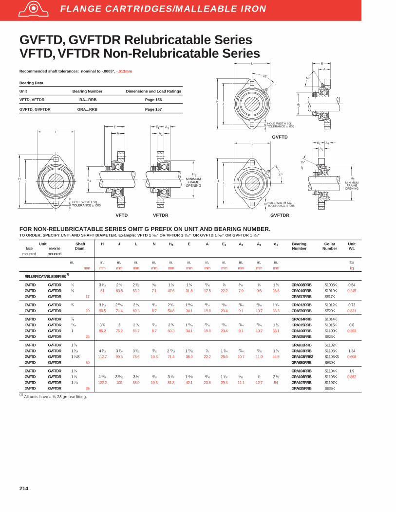
214
N
L
HOLE WIDTH SQ.TOLERANCE ± .005
JH
45°
d
A
E
50°
1
N
L
HOLE WIDTH SQ.TOLERANCE ± .005
JH
E
A
25°
H
MINIMUMFRAME
OPENING
1
37°2
1 A3
GVFTD, GVFTDR Relubricatable SeriesVFTD, VFTDR Non-Relubricatable SeriesRecommended shaft tolerances: nominal to -.0005", -.013mm
Bearing Data
Unit Bearing Number Dimensions and Load Ratings
VFTD, VFTDR RA...RRB Page 156
GVFTD, GVFTDR GRA...RRB Page 157
GVFTD
GVFTDR
N
L
HOLE WIDTH SQ.TOLERANCE ± .005
JH d
A
1
E
A
E
H
MINIMUMFRAME
OPENING
1
2
1 A3
VFTD VFTDR
FOR NON-RELUBRICATABLE SERIES OMIT G PREFIX ON UNIT AND BEARING NUMBER.TO ORDER, SPECIFY UNIT AND SHAFT DIAMETER. Example: VFTD 1 3⁄16" OR VFTDR 1 3⁄16" OR GVFTD 1 3⁄16" OR GVFTDR 1 3⁄16"
Unit Shaft H J L N H 2 E A E1 A3 A1 d1 Bearing Collar Unitface reverse Diam. Number Number Wt.
mounted mounted
in. in. in. in. in. in. in. in. in. in. in. in. lbsmm mm mm mm mm mm mm mm mm mm mm mm kg
RELUBRICATABLE SERIES(1)
GVFTD GVFTDR 1⁄2 3 3⁄16 2 1⁄2 2 3⁄329⁄32 1 7⁄8 1 1⁄4 11⁄16
7⁄8 5⁄163⁄8 1 1⁄8 GRA008RRB S1008K 0.54
GVFTD GVFTDR 5⁄8 81 63.5 53.2 7.1 47.6 31.8 17.5 22.2 7.9 9.5 28.6 GRA010RRB S1010K 0.245GVFTD GVFTDR 17 GRAE17RRB SE17K
GVFTD GVFTDR 3⁄4 3 9⁄16 2 13⁄16 2 3⁄8 11⁄32 2 5⁄32 1 11⁄3225⁄32
59⁄6423⁄64
27⁄64 1 5⁄16 GRA012RRB S1012K 0.73GVFTD GVFTDR 20 90.5 71.4 60.3 8.7 54.8 34.1 19.8 23.4 9.1 10.7 33.3 GRAE20RRB SE20K 0.331
GVFTD GVFTDR 7⁄8 GRA014RRB S1014KGVFTD GVFTDR 15⁄16 3 3⁄4 3 2 5⁄8 11⁄32 2 3⁄8 1 11⁄32
25⁄3259⁄64
23⁄6427⁄64 1 1⁄2 GRA015RRB S1015K 0.8
GVFTD GVFTDR 1 95.2 76.2 66.7 8.7 60.3 34.1 19.8 23.4 9.1 10.7 38.1 GRA100RRB S1100K 0.363GVFTD GVFTDR 25 GRAE25RRB SE25K
GVFTD GVFTDR 1 1⁄8 GRA102RRB S1102KGVFTD GVFTDR 1 3⁄16 4 7⁄16 3 9⁄16 3 3⁄32
13⁄32 2 13⁄16 1 17⁄327⁄8 1 3⁄64
27⁄6415⁄32 1 3⁄4 GRA103RRB S1103K 1.34
GVFTD GVFTDR 1 1⁄4S 112.7 90.5 78.6 10.3 71.4 38.9 22.2 26.6 10.7 11.9 44.5 GRA103RRB2 S1103K3 0.608GVFTD GVFTDR 30 GRAE30RRB SE30K
GVFTD GVFTDR 1 1⁄4 GRA104RRB S1104K 1.9GVFTD GVFTDR 1 3⁄8 4 13⁄16 3 15⁄16 3 1⁄2 13⁄32 3 7⁄32 1 21⁄32
15⁄16 1 5⁄327⁄16
1⁄2 2 1⁄8 GRA106RRB S1106K 0.862GVFTD GVFTDR 1 7⁄16 122.2 100 88.9 10.3 81.8 42.1 23.8 29.4 11.1 12.7 54 GRA107RRB S1107KGVFTD GVFTDR 35 GRAE35RRB SE35K
(1) All units have a 1⁄4-28 grease fitting.
FLANGE CARTRIDGES/MALLEABLE IRON
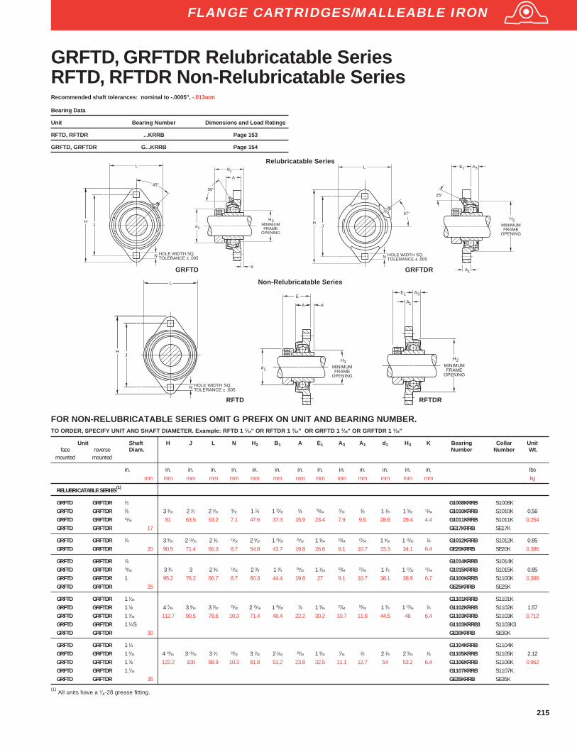
215
Recommended shaft tolerances: nominal to -.0005", -.013mm
Bearing Data
Unit Bearing Number Dimensions and Load Ratings
RFTD, RFTDR ...KRRB Page 153
GRFTD, GRFTDR G...KRRB Page 154
Relubricatable Series
N
L
HOLE WIDTH SQ.TOLERANCE ± .005
JH
E
25°
A
H
MINIMUMFRAME
OPENING
37°
A
2
1
1 3
N
L
HOLE WIDTH SQ.TOLERANCE ± .005
JH
45°
GRFTD GRFTDR
Non-Relubricatable Series
d1
A
E
H
MINIMUMFRAME
OPENING
K
3
N
L
HOLE WIDTH SQ.TOLERANCE ± .005
JH
RFTD RFTDR
A
H
MINIMUMFRAME
OPENING
A
1
2
E1 3
Unit Shaft H J L N H 2 B1 A E1 A3 A1 d1 H3 K Bearing Collar Unitface reverse Diam. Number Number Wt.
mounted mounted
in. in. in. in. in. in. in. in. in. in. in. in. in. in. lbsmm mm mm mm mm mm mm mm mm mm mm mm mm mm kg
RELUBRICATABLE SERIES(1)
GRFTD GRFTDR 1⁄2 G1008KRRB S1008KGRFTD GRFTDR 5⁄8 3 3⁄16 2 1⁄2 2 3⁄32 9⁄32 1 7⁄8 1 15⁄32 5⁄8 59⁄64 5⁄16 3⁄8 1 1⁄8 1 5⁄32 11⁄64 G1010KRRB S1010K 0.56GRFTD GRFTDR 11⁄16 81 63.5 53.2 7.1 47.6 37.3 15.9 23.4 7.9 9.5 28.6 29.4 4.4 G1011KRRB S1011K 0.254GRFTD GRFTDR 17 GE17KRRB SE17K
GRFTD GRFTDR 3⁄4 3 9⁄16 2 13⁄16 2 3⁄8 11⁄32 2 5⁄32 1 23⁄32 25⁄32 1 3⁄64 23⁄64 27⁄64 1 5⁄16 1 11⁄32 1⁄4 G1012KRRB S1012K 0.85GRFTD GRFTDR 20 90.5 71.4 60.3 8.7 54.8 43.7 19.8 26.6 9.1 10.7 33.3 34.1 6.4 GE20KRRB SE20K 0.386
GRFTD GRFTDR 7⁄8 G1014KRRB S1014KGRFTD GRFTDR 15⁄16 3 3⁄4 3 2 5⁄8 11⁄32 2 3⁄8 1 3⁄4 25⁄32 1 1⁄16 23⁄64 27⁄64 1 1⁄2 1 17⁄32 17⁄64 G1015KRRB S1015K 0.85GRFTD GRFTDR 1 95.2 76.2 66.7 8.7 60.3 44.4 19.8 27 9.1 10.7 38.1 38.9 6.7 G1100KRRB S1100K 0.386GRFTD GRFTDR 25 GE25KRRB SE25K
GRFTD GRFTDR 1 1⁄16 G1101KRRB S1101KGRFTD GRFTDR 1 1⁄8 4 7⁄16 3 9⁄16 3 3⁄32 13⁄32 2 13⁄16 1 29⁄32 7⁄8 1 3⁄16 27⁄64 15⁄32 1 3⁄4 1 13⁄16 1⁄4 G1102KRRB S1102K 1.57GRFTD GRFTDR 1 3⁄16 112.7 90.5 78.6 10.3 71.4 48.4 22.2 30.2 10.7 11.9 44.5 46 6.4 G1103KRRB S1103K 0.712GRFTD GRFTDR 1 1⁄4S G1103KRRB3 S1103K3GRFTD GRFTDR 30 GE30KRRB SE30K
GRFTD GRFTDR 1 1⁄4 G1104KRRB S1104KGRFTD GRFTDR 1 5⁄16 4 13⁄16 3 15⁄16 3 1⁄2 13⁄32 3 7⁄32 2 1⁄64 15⁄16 1 9⁄32 7⁄16 1⁄2 2 1⁄8 2 3⁄32 1⁄4 G1105KRRB S1105K 2.12GRFTD GRFTDR 1 3⁄8 122.2 100 88.9 10.3 81.8 51.2 23.8 32.5 11.1 12.7 54 53.2 6.4 G1106KRRB S1106K 0.962GRFTD GRFTDR 1 7⁄16 G1107KRRB S1107KGRFTD GRFTDR 35 GE35KRRB SE35K
FOR NON-RELUBRICATABLE SERIES OMIT G PREFIX ON UNIT AND BEARING NUMBER.TO ORDER, SPECIFY UNIT AND SHAFT DIAMETER. Example: RFTD 1 3⁄16" OR RFTDR 1 3⁄16" OR GRFTD 1 3⁄16" OR GRFTDR 1 3⁄16"
GRFTD, GRFTDR Relubricatable SeriesRFTD, RFTDR Non-Relubricatable Series
FLANGE CARTRIDGES/MALLEABLE IRON
(1) All units have a 1⁄4-28 grease fitting.
d
A
B
50°
1
K
MINIMUMFRAME
OPENING
1
3H
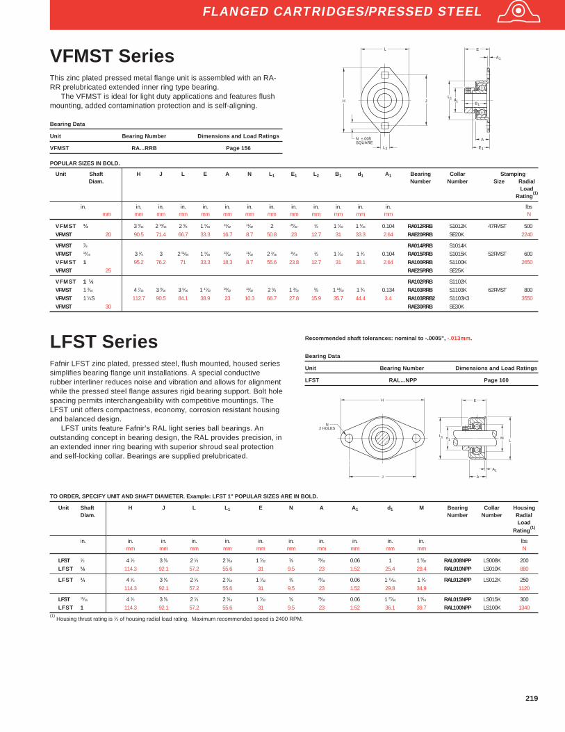
219
VFMST SeriesThis zinc plated pressed metal flange unit is assembled with an RA-RR prelubricated extended inner ring type bearing.
The VFMST is ideal for light duty applications and features flushmounting, added contamination protection and is self-aligning.
Bearing Data
Unit Bearing Number Dimensions and Load Ratings
VFMST RA...RRB Page 156
Unit Shaft H J L E A N L 1 E1 L2 B1 d1 A1 Bearing Collar StampingDiam. Number Number Size Radial
LoadRating
(1)
in. in. in. in. in. in. in. in. in. in. in. in. in. lbsmm mm mm mm mm mm mm mm mm mm mm mm mm N
VFMST 3⁄4 3 9⁄16 2 13⁄16 2 5⁄8 1 5⁄1621⁄32
11⁄32 2 29⁄321⁄2 1 7⁄32 1 5⁄16 0.104 RA012RRB S1012K 47FMST 500
VFMST 20 90.5 71.4 66.7 33.3 16.7 8.7 50.8 23 12.7 31 33.3 2.64 RAE20RRB SE20K 2240
VFMST 7⁄8 RA014RRB S1014KVFMST 15⁄16 3 3⁄4 3 2 51⁄64 1 5⁄16
23⁄3211⁄32 2 3⁄16
15⁄161⁄2 1 7⁄32 1 1⁄2 0.104 RA015RRB S1015K 52FMST 600
VFMST 1 95.2 76.2 71 33.3 18.3 8.7 55.6 23.8 12.7 31 38.1 2.64 RA100RRB S1100K 2650VFMST 25 RAE25RRB SE25K
VFMST 1 1⁄8 RA102RRB S1102KVFMST 1 3⁄16 4 7⁄16 3 9⁄16 3 5⁄16 1 17⁄32
29⁄3213⁄32 2 5⁄8 1 3⁄32
5⁄8 1 13⁄32 1 3⁄4 0.134 RA103RRB S1103K 62FMST 800VFMST 1 1⁄4S 112.7 90.5 84.1 38.9 23 10.3 66.7 27.8 15.9 35.7 44.4 3.4 RA103RRB2 S1103K3 3550VFMST 30 RAE30RRB SE30K
d
A
E
1
1
L1
B1
A
1E
L
H J
2L
N ±.005SQUARE
TO ORDER, SPECIFY UNIT AND SHAFT DIAMETER. Example: LFST 1" POPULAR SIZES ARE IN BOLD.
Unit Shaft H J L L 1 E N A A1 d1 M Bearing Collar HousingDiam. Number Number Radial
LoadRating
(1)
in. in. in. in. in. in. in. in. in. in. in. lbsmm mm mm mm mm mm mm mm mm mm N
LFST 1⁄2 4 1⁄2 3 5⁄8 2 1⁄4 2 3⁄16 1 7⁄32 3⁄8 29⁄32 0.06 1 1 5⁄32 RAL008NPP LS008K 200LFST 5⁄8 114.3 92.1 57.2 55.6 31 9.5 23 1.52 25.4 29.4 RAL010NPP LS010K 880
LFST 3⁄4 4 1⁄2 3 5⁄8 2 1⁄4 2 3⁄16 1 7⁄32 3⁄8 29⁄32 0.06 1 11⁄64 1 3⁄8 RAL012NPP LS012K 250114.3 92.1 57.2 55.6 31 9.5 23 1.52 29.8 34.9 1120
LFST 15⁄16 4 1⁄2 3 5⁄8 2 1⁄4 2 3⁄16 1 7⁄32 3⁄8 29⁄32 0.06 1 27⁄64 1 9⁄16 RAL015NPP LS015K 300LFST 1 114.3 92.1 57.2 55.6 31 9.5 23 1.52 36.1 39.7 RAL100NPP LS100K 1340
(1) Housing thrust rating is 1⁄3 of housing radial load rating. Maximum recommended speed is 2400 RPM.
LFST SeriesFafnir LFST zinc plated, pressed steel, flush mounted, housed seriessimplifies bearing flange unit installations. A special conductiverubber interliner reduces noise and vibration and allows for alignmentwhile the pressed steel flange assures rigid bearing support. Bolt holespacing permits interchangeability with competitive mountings. TheLFST unit offers compactness, economy, corrosion resistant housingand balanced design.
LFST units feature Fafnir’s RAL light series ball bearings. Anoutstanding concept in bearing design, the RAL provides precision, inan extended inner ring bearing with superior shroud seal protectionand self-locking collar. Bearings are supplied prelubricated.
Recommended shaft tolerances: nominal to -.0005", -.013mm.
Bearing Data
Unit Bearing Number Dimensions and Load Ratings
LFST RAL...NPP Page 160
H
J
N2 HOLES
E
ML
Ld
A
A
1
1
1
FLANGED CARTRIDGES/PRESSED STEEL
POPULAR SIZES IN BOLD.

220
Unit Shaft H A J N H 2 A1 E K d1 Bolt P N 2 Bearing Collar Stamping(2)
UnitDiam. Hole Size flange hole Number Number Size Radial Wt.
Width diam. to Load` short long clear sq. Rating
(1)
shank shank shank
in. in. in. in. in. in. in. in. in. in. in. in. in. in. lbs. lbsmm mm mm mm mm mm mm mm mm mm mm mm mm mm N kg
RR 1⁄2 3 3⁄16 9⁄16 2 1⁄2 9⁄32 1 15⁄16 0.15 1 15⁄32 1 1⁄8 1⁄4 0.006 0.1 13⁄32 1008KRRB S1008K 40MS 600 0.65RR 5⁄8 81 14.2 63.5 7.1 49.2 3.8 25.4 11.9 28.6 6.4 0.15 2.54 10.3 1010KRRB S1010K 2650 0.295RR 17 E17KRRB SE17K
RR 3⁄4 3 9⁄16 5⁄8 2 13⁄16 11⁄32 2 3⁄16 0.166 1 1⁄8 19⁄32 1 5⁄16 5⁄16 0.021 0.115 1⁄2 1012KRRB S1012K 47MS 700 0.89RR 20 90.5 15.8 71.4 8.7 55.6 4.22 28.6 15.1 33.3 7.9 0.53 2.92 12.7 E20KRRB SE20K 3100 0.404
RR 7⁄8 1014KRRB S1014KRR 15⁄16 3 3⁄4 11⁄16 3 11⁄32 2 3⁄8 0.166 1 1⁄8 19⁄32 1 1⁄2 5⁄16 0.021 0.115 1⁄2 1015KRRB S1015K 52MS 800 1.08RR 1 95.2 17.4 76.2 8.7 60.3 4.22 28.6 15.1 38.1 7.9 0.53 2.92 12.7 1100KRRB S1100K 3550 0.49RR 25 E25KRRB SE25K
RR 1 1⁄8 1102KRRB S1102KRR 1 3⁄16 4 7⁄16 11⁄16 3 9⁄16 13⁄32 2 13⁄16 0.208 1 9⁄32 5⁄8 1 3⁄4 3⁄8 0.011 0.104 19⁄32 1103KRRB S1103K 62MS 1100 1.66RR 1 1⁄4S 112.7 17.4 90.5 10.3 71.4 5.28 32.5 15.9 44.5 9.5 0.28 2.64 15.1 1103KRRB3 S1103K3 4900 0.753RR 30 E30KRRB SE30K
RR 1 1⁄4 1104KRRB S1104KRR 1 5⁄16 4 13⁄16 3⁄4 3 15⁄16 13⁄16 3 3⁄16 0.208 1 3⁄8 5⁄8 2 1⁄8 3⁄8 0.011 0.104 19⁄32 1105KRRB S1105K 72MS 1400 2.12RR 1 3⁄8 122.2 19 100 10.3 81 5.28 34.9 15.9 54 9.5 0.28 2.64 15.1 1106KRRB S1106K 6220 0.962RR 1 7⁄16 1107KRRB S1107RR 35 E35KRRB SE35K
RR 1 1⁄2 5 13⁄16 13⁄16 4 11⁄16 17⁄32 3 9⁄16 0.268 1 1⁄2 23⁄32 2 3⁄8 1⁄2 0.013 0.107 49⁄64 1108KRRB S1108KT 80MS 1700 2.52RR 1 9⁄16 147.6 20.6 119.1 13.5 90.5 6.8 38.1 18.3 60.3 12.7 0.33 2.72 19.4 1109KRRB S1109KT 7500 1.143RR 40 E40KRRB SE40K
RR 1 5⁄8 5 7⁄8 7⁄8 4 3⁄4 17⁄32 3 13⁄16 0.268 1 1⁄2 23⁄32 2 1⁄2 1⁄2 0.013 0.107 49⁄64 1110KRRB S1110K 85MS 1700 3.64RR 1 11⁄16 149.2 22.2 120.6 13.5 96.8 6.8 38.1 18.3 63.5 12.7 0.33 2.72 19.4 1111KRRB S1111K 7500 1.651RR 45 E45KRRB SE45K
RR 1 7⁄8 6 1⁄8 7⁄8 5 17⁄32 4 0.298 1 21⁄32 13⁄16 2 3⁄4 1⁄2 0 0.077 49⁄64 1114KRRB S1114K 90MS 1900 4.14RR 1 15⁄16 155.6 22.2 127 13.5 101.6 7.56 42.1 20.6 69.8 12.7 0 1.96 19.4 1115KRRB S1115K 8500 1.878RR 50 E50KRRB SE50K
RR 2 1200KRRB S1200KRR 2 1⁄8 6 9⁄16 15⁄16 5 7⁄16 17⁄32 4 7⁄16 0.298 1 7⁄8 15⁄16 3 1⁄2 0 0.077 49⁄64 1202KRRB S1202K 100MS 2300 5RR 2 3⁄16 166.7 23.8 138.1 13.5 112.7 7.56 47.6 23.8 76.2 12.7 0 1.96 19.4 1203KRRB S1203K 10200 2.268RR 55 E55KRRB SE55K
RR Flangette UnitsFafnir Flangette Units consist of two interchangeable pressed steel,zinc plated flanges which house a standard Fafnir Wide Inner RingBall Bearing with Self-Locking Collar. The spherical inside surfaces ofeach pair of flanges mates with the spherical outside surface of thebearing’s outer ring to provide initial self-alignment.
The RR Flangette is equipped with the KRRB (R-Seal) side innerring ball bearing. All units are non-relubricatable.
Recommended shaft tolerances: 1/2"-1 15/16", nominal to -.0005", -.013 mm;2"- 2 23/16", nominal to -.0010", -.025 mm.
Bearing Data
Unit Bearing Number Dimensions and Load Ratings
RR KRRB Page 153
J
N
H30°
HOLE WIDTH SQ.TOLERANCE ± .005
J
30°
STAMPING SIZES40MS-72MS
STAMPING SIZES80MS-100MS
d
H
MINIMUMFRAME
OPENING
E K
A
P
N
1
2
1
2
A
(1) Thrust ratings for stampings are 50% of radial ratings.
(2) Stampings must be ordered in pairs to assemble bearing.
FLANGETTES/PRESSED STEEL
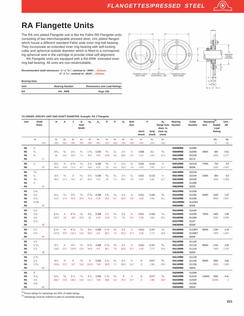
221
Unit Shaft H A J N H 2 A1 E K d1 Bolt P N 2 Bearing Collar Stamping(2)
Unit .Diam. Hole Size flange hole Number Number Size Radial Wt
Width diam. to Loadshort long clear sq. Ratingshank shank shank
in. in. in. in. in. in. in. in. in. in. in. in. in. in. lbs. lbsmm mm mm mm mm mm mm mm mm mm mm mm mm mm N kg
RA 1⁄2 RA008RRB S1008KRA 9⁄16 3 3⁄16
9⁄16 2 1⁄2 9⁄32 1 15⁄16 0.150 15⁄167⁄32 1 1⁄8 1⁄4 0.006 0.1 13⁄32 RA009RRB S1009K 40MS 600 0.61
RA 5⁄8 81 14.2 63.5 7.1 49.2 3.81 23.8 5.6 28.6 6.4 0.15 2.54 10.3 RA010RRB S1010K 2650 0.277RA 17 RAE17RRB SE17K
RA 3⁄4 3 9⁄165⁄8 2 13⁄16
11⁄32 2 3⁄16 0.166 63⁄641⁄4 1 5⁄16
5⁄16 0.021 0.115 1⁄2 RA012RRB S1012K 47MS 700 0.8RA 20 90.5 15.8 71.4 8.7 55.6 4.22 25 6.4 33.3 7.9 0.53 2.92 12.7 RAE20RRB SE20K 3100 0.363
RA 13⁄16 RA013RRB S1013KRA 7⁄8 3 3⁄4 11⁄16 3 11⁄32 2 3⁄8 0.166 63⁄64
9⁄32 1 1⁄2 5⁄16 0.021 0.115 1⁄2 RA014RRB S1014K 52MS 800 0.9RA 15⁄16 95.2 17.4 76.2 8.7 60.3 4.22 25 7.1 38.1 7.9 0.53 2.92 12.7 RA015RRB S1015K 3550 0.408RA 1 RA100RRB S1100KRA 25 RAE25RRB SE25K
RA 1 1⁄16 RA101RRB S1103KRA 1 1⁄8 4 7⁄16
11⁄16 3 9⁄1613⁄32 2 13⁄16 0.208 1 9⁄64
17⁄64 1 3⁄4 3⁄8 0.011 0.104 19⁄32 RA102RRB S1102K 62MS 1100 1.47RA 1 3⁄16 112.7 17.4 90.5 10.3 71.4 5.28 29.0 6.7 44.5 9.5 0.28 2.64 15.1 RA103RRB S1103K 4900 0.667RA 1 1⁄4S RA103RRB3 S1103K3RA 30 RAE30RRB SE30K
RA 1 1⁄4 RA104RRB S1104KRA 1 5⁄16 4 13⁄16
3⁄4 3 15⁄1613⁄32 3 3⁄16 0.208 1 1⁄4 19⁄64 2 1⁄8 3⁄8 0.011 0.104 19⁄32 RA105RRB S1105K 72MS 1400 1.96
RA 1 3⁄8 122.2 19 100 10.3 81 5.28 31.8 7.5 54 9.5 0.28 2.64 15.1 RA106RRB S1106K 6220 0.889RA 1 7⁄16 RA107RRB S1107RA 35 RAE35RRB SE35K
RA 1 1⁄2 5 13⁄1613⁄16 4 11⁄16
17⁄32 3 9⁄16 0.268 1 27⁄6419⁄64 2 3⁄8 1⁄2 0.013 0.107 49⁄64 RA108RRB S1108KT 80MS 1700 3.19
RA 1 9⁄16 147.6 20.6 119.1 13.5 90.5 6.8 36.1 7.5 60.3 12.7 0.33 2.72 19.4 RA109RRB S1109KT 7500 1.447RA 40 RAE40RRB SE40K
RA 1 5⁄8 RA110RRB S1110KRA 1 11⁄16 5 7⁄8 7⁄8 4 3⁄4 17⁄32 3 13⁄16 0.268 1 27⁄64
19⁄64 2 1⁄2 1⁄2 0.013 0.107 49⁄64 RA111RRB S1111K 85MS 1700 3.26RA 1 3⁄4 149.2 22.2 120.6 13.5 96.8 6.8 36.1 7.5 63.5 12.7 0.33 2.72 19.4 RA112RRB S1112K 7500 1.479RA 45 RAE45RRB SE45K
RA 1 13⁄16 RA113RRB S1113KRA 1 7⁄8 6 1⁄8 7⁄8 5 17⁄32 4 0.300 1 7⁄16
9⁄32 2 3⁄4 1⁄2 0 0.077 49⁄64 RA114RRB S1114K 90MS 1900 3.68RA 1 15⁄16 155.6 22.2 127 13.5 101.6 7.56 36.5 7.1 69.8 12.7 0 1.96 19.4 RA115RRB S1115K 8500 1.669RA 50 RAE50RRB SE50K
RA 2 RA200RRB S1200KRA 2 1⁄16 6 9⁄16
15⁄16 5 7⁄1617⁄32 4 7⁄16 0.300 1 19⁄32
29⁄64 3 1⁄2 0 0.077 49⁄64 RA201RRB S1201K 100MS 2300 4.41RA 2 1⁄8 166.7 23.8 138.1 13.5 112.7 7.56 40.5 8.3 76.2 12.7 0 1.96 19.4 RA202RRB S1202K 10200 2RA 2 3⁄16 RA203RRB S1203KRA 55 RAE55RRB SE55K
RA Flangette UnitsThe RA zinc plated Flangette unit is like the Fafnir RR Flangette unitsconsisting of two interchangeable pressed steel, zinc plated flangeswhich house a different standard Fafnir wide inner ring ball bearing.They incorporate an extended inner ring bearing with self-lockingcollar and spherical outside diameter which is fitted to a correspond-ing spherical seat in the cartridge to provide initial self-alignment.
RA Flangette units are equipped with a RA-RRB extended innerring ball bearing. All units are non-relubricatable.
Recommended shaft tolerances: 1/2"-1 15/16", nominal to -.0005", -.013mm;2"- 2 3/16", nominal to -.0010", -.025mm.
Bearing Data
Unit Bearing Number Dimensions and Load Ratings
RA RA...RRB Page 156
TO ORDER, SPECIFY UNIT AND SHAFT DIAMETER. Example: RA 1"Flangette
(1)Thrust ratings for stampings are 50% of radial ratings.
(2) Stampings must be ordered in pairs to assemble bearing.
J
N
H30°
HOLE WIDTH SQ.TOLERANCE ± .005
J
30°
STAMPING SIZES40MS-72MS
STAMPING SIZES80MS-100MS
H
MINIMUMFRAME
OPENING
E
A
K
A
P
N
1
2
2d1
2
A
FLANGETTES/PRESSED STEEL

222
Unit Shaft L H A J N H 2 A1 E K d1 Bolt P N 2 Bearing Collar Stamping UnitDiam. Hole Size flange hole Number Number Size Radial Wt.
Width diam. to Loadshort long clear sq. Ratingshank shank shank
in. in. in. in. in. in. in. in. in. in. in. in. in. in. in. lbs. lbsmm mm mm mm mm mm mm mm mm mm mm mm mm mm mm N kg
RRT 1⁄2 2 5⁄16 3 3⁄169⁄16 2 1⁄2 9⁄32 1 15⁄16 0.150 15⁄16
7⁄32 1 1⁄8 1⁄4 0.006 0.1 13⁄32 1008KRRB S1008K 40MST 600 0.47RRT 5⁄8 58.7 81 14.2 63.5 7.1 49.2 3.81 23.8 5.6 28.6 6.4 0.15 2.54 10.3 1010KRRB S1010K 2650 0.213RRT 17 E17KRRB SE17K
RRT 3⁄4 2 5⁄8 3 9⁄165⁄8 2 13⁄16
11⁄32 2 3⁄16 0.166 63⁄641⁄4 1 5⁄16
5⁄16 0.021 0.115 1⁄2 1012KRRB S1012K 47MST 700 0.66RRT 20 66.7 90.5 15.8 71.4 8.7 55.6 4.22 25 6.4 33.3 7.9 0.53 2.92 12.7 E20KRRB SE20K 3100 0.299
RRT 7⁄8 1014KRRB S1014KRRT 15⁄16 2 51⁄64 3 3⁄4 11⁄16 3 11⁄32 2 3⁄8 0.166 63⁄64 9⁄32 1 1⁄2 5⁄16 0.021 0.115 1⁄2 1015KRRB S1015K 52MST 800 0.73RRT 1 71 95.2 17.4 76.2 8.7 60.3 4.22 25 7.1 38.1 7.9 0.53 2.92 12.7 1100KRRB S1100K 3550 0.331RRT 25 E25KRRB SE25K
RRT 1 1⁄16 1101KRRB S1103KRRT 1 1⁄8 3 5⁄16 4 7⁄16 11⁄16 3 9⁄16 13⁄32 2 13⁄16 0.208 1 9⁄64 17⁄64 1 3⁄4 3⁄8 0.011 0.104 19⁄32 1102KRRB S1102K 62MST 1100 1.17RRT 1 3⁄16 84.1 112.7 17.4 90.5 10.3 71.4 5.28 29 6.7 44.5 9.5 0.28 2.64 15.1 1103KRRB S1103K 4900 0.531RRT 1 1⁄4S 1103KRRB3 S1103K3RRT 30 E30KRRB SE30K
RRT 1 1⁄4 1104KRRB S1104KRRT 1 5⁄16 3 11⁄16 4 15⁄16
7⁄8 3 15⁄1613⁄32 3 3⁄16 0.208 1 17⁄64
17⁄64 2 1⁄8 3⁄8 0.011 0.104 19⁄32 1105KRRB S1105K 72MST 1400 1.05RRT 1 3⁄8 93.7 125.4 22.2 100 10.3 81 5.28 32.1 6.7 54 9.5 0.28 2.64 15.1 1106KRRB S1106K 6220 0.476RRT 1 7⁄16 1107KRRB S1107KRRT 35 E35KRRB SE35K
Unit Shaft L H A J N H 2 A1 E K d1 Bolt P N 2 Bearing Collar Stamping UnitDiam. Hole Size flange hole Number Number Size Radial Wt.
Width diam. to Loadshort long clear sq. Ratingshank shank shank
in. in. in. in. in. in. in. in. in. in. in. in. in. in. in. lbs. lbsmm mm mm mm mm mm mm mm mm mm mm mm mm mm mm N kg
RAT 1⁄2 2 5⁄16 3 3⁄16 9⁄16 2 1⁄2 9⁄32 1 15⁄16 0.150 15⁄16 7⁄32 1 1⁄8 1⁄4 0.006 0.1 13⁄32 RA008RRB S1008K 40MST 600 0.47RAT 5⁄8 58.7 81 14.2 63.5 7.1 49.2 3.81 23.8 5.6 28.6 6.4 0.15 2.54 10.3 RA010RRB S1010K 2650 0.213RAT 17 RAE17RRB SE17K
RAT 3⁄4 2 5⁄8 3 9⁄165⁄8 2 13⁄16
11⁄32 2 3⁄16 0.166 63⁄641⁄4 1 5⁄16
5⁄16 0.021 0.115 1⁄2 RA012RRB S1012K 47MST 700 0.66RAT 20 66.7 90.5 15.8 71.4 8.7 55.6 4.22 25 6.4 33.3 7.9 0.53 2.92 12.7 RAE20RRB SE20K 3100 0.299
RAT 7⁄8 RA014RRB S1014KRAT 15⁄16 2 51⁄64 3 3⁄4 11⁄16 3 11⁄32 2 3⁄8 0.166 63⁄64
9⁄32 1 1⁄2 5⁄16 0.021 0.115 1⁄2 RA015RRB S1015K 52MST 800 0.73RAT 1 71 95.2 17.4 76.2 8.7 60.3 4.22 25 7.1 38.1 7.9 0.53 2.92 12.7 RA100RRB S1100K 3550 0.331RAT 25 RAE25RRB SE25K
RAT 1 1⁄16 RA101RRB S1103KRAT 1 1⁄8 3 5⁄16 4 7⁄16
11⁄16 3 9⁄1613⁄32 2 13⁄16 0.208 1 9⁄64
17⁄64 1 3⁄4 3⁄8 0.011 0.104 19⁄32 RA102RRB S1102K 62MST 1100 1.17RAT 1 3⁄16 84.1 112.7 17.4 90.5 10.3 71.4 5.28 29 6.7 44.5 9.5 0.28 2.64 15.1 RA103RRB S1103K 4900 0.531RAT 1 1⁄4S RA103RRB2 S1103K3RAT 30 RAE30RRB SE30K
RAT 1 1⁄4 RA104RRB S1104KRAT 1 5⁄16 3 11⁄16 4 15⁄16 7⁄8 3 15⁄16 13⁄32 3 3⁄16 0.208 1 17⁄64 17⁄64 2 1⁄8 3⁄8 0.011 0.104 19⁄32 RA105RRB S1105K 72MST 1400 1.05RAT 1 3⁄8 93.7 125.4 22.2 100 10.3 81 5.28 32.1 6.7 54 9.5 0.28 2.64 15.1 RA106RRB S1106K 6220 0.476RAT 1 7⁄16 RA107RRB S1107KRAT 35 RAE35RRB SE35K
TO ORDER, SPECIFY UNIT AND SHAFT DIAMETER. Example: RRT 1"Flangette
RAT, RRT Two BoltFlangette UnitsThe Fafnir two bolt zinc plated Flangette units are designed forinstallations where the standard three bolt flangettes cannot be usedbecause of space limitations.
Like the standard three-bolt Flangette, they are available with theRA-RRB extended inner ring ball bearings (RAT) and the KRRB wideinner ring ball bearings (RRT) with self locking collars.
All units are non-relubricatable.
Recommended shaft tolerances: 1/2"-1 15/16", nominal to -.0005", -.013mm;
2"- 2 3/16", nominal to -.0010", -.025mm.
Bearing Data
Unit Bearing Number Dimensions and Load Ratings
RAT RA...RRB Page 156
RRT ...KRRB Page 153
HOLE WIDTH (SQ)TOLERANCE ± .005
N
L
JH
d
H
MINIMUMFRAME
OPENING
E K
A
P
N
1
2
2
1
A2
d
H
MINIMUMFRAME
OPENING
E K
A
P
N
1
1
2
2
A
A2
RAT Series RRT Series
TO ORDER, SPECIFY UNIT AND SHAFT DIAMETER. Example: RAT 1" Flangette
FLANGETTES/PRESSED STEEL

223
Unit Shaft H 3 H A J N H 2 A1 E K d1 H1 L1 Bolt P N 2 Bearing Collar Stamping UnitDiam. Hole Size flange hole Number Number Size Radial Wt.
Width diam. to Loadshort long clear sq. Ratingshank shank shank
in. in. in. in. in. in. in. in. in. in. in. in. in. in. in. in. in. lbs. lbsmm mm mm mm mm mm mm mm mm mm mm mm mm mm mm mm mm N kg
RRTR 3⁄4 3 3 9⁄16 5⁄8 2 13⁄16 11⁄32 2 3⁄16 0.166 1 1⁄8 19⁄32 1 5⁄16 1 5⁄16 1 1⁄16 5⁄16 0.006 0.1 1⁄2 1012KRRB S1012K 47MSTR 700 0.69RRTR 20 76.2 90.5 15.8 71.4 8.7 55.6 4.22 28.6 15.1 33.3 33.3 27 7.9 0.15 2.54 12.7 E20KRRB SE20K 3100 0.313
RRTR 7⁄8 1014KRRB S1014KRRTR 15⁄16 3 1⁄8 3 3⁄4 11⁄16 3 11⁄32 2 3⁄8 0.166 1 1⁄8 19⁄32 1 1⁄2 1 3⁄8 1 3⁄32 5⁄16 0.021 0.115 1⁄2 1015KRRB S1015K 52MSTR 800 0.78RRTR 1 79.4 95.2 17.4 76.2 8.7 60.3 4.22 28.6 15.1 38.1 34.9 27.8 7.9 0.53 2.92 12.7 1100KRRB S1100K 3550 0.354RRTR 25 E25KRRB SE25K
RRTR 1 1⁄16 1101KRRB S1103KRRTR 1 1⁄8 3 11⁄16 4 7⁄16 11⁄16 3 9⁄16 13⁄32 2 13⁄16 0.208 1 9⁄32 5⁄8 1 3⁄4 1 1⁄2 1 3⁄8 0.011 0.104 19⁄32 1102KRRB S1102K 62MSTR 1100 1.16RRTR 1 3⁄16 93.7 112.7 17.4 90.5 10.3 71.4 5.28 32.5 15.9 44.5 38.1 25.4 9.5 0.28 2.64 15.1 1103KRRB S1103K 4900 0.526RRTR 1 1⁄4S 1103KRRB3 S1103K3RRTR 30 E30KRRB SE30K
RRTR 1 1⁄4 1104KRRB S1104KRRTR 1 5⁄16 4 5⁄32 5 3⁄4 3 15⁄16 13⁄32 3 3⁄16 0.208 1 3⁄8 41⁄64 2 1⁄8 1 3⁄4 1 17⁄64 3⁄8 0.011 0.104 19⁄32 1105KRRB S1105K 72MSTR 1400 1.55RRTR 1 3⁄8 105.6 127 19 100 10.3 81 5.28 34.9 16.3 54 44.4 32.1 9.5 0.28 2.64 15.1 1106KRRB S1106K 6300 0.703RRTR 1 7⁄16 1107KRRB S1107RRTR 35 E35KRRB SE35K
Unit Shaft H 3 H A J N H 2 A1 E K d1 H1 L1 Bolt q N 2 Bearing Collar Stamping Unit Diam. Hole Size flange hole Number Number Size Radial Wt.
Width diam. to Loadshort long clear sq. Ratingshank shank shank
in. in. in. in. in. in. in. in. in. in. in. in. in. in. in. in. in. lbs. lbsmm mm mm mm mm mm mm mm mm mm mm mm mm mm mm mm mm N kg
RATR 3⁄4 3 3 9⁄16 5⁄8 2 13⁄16 11⁄32 2 3⁄16 0.166 63⁄64 1⁄4 1 5⁄16 1 5⁄16 1 1⁄16 5⁄16 0.006 0.1 1⁄2 RA012RRB S1012K 47MSTR 700 0.69RATR 20 76.2 90.5 15.8 71.4 8.7 55.6 4.22 25 6.4 33.3 33.3 27 7.9 0.15 2.54 12.7 RAE20RRB SE20K 3100 0.313
RATR 7⁄8 RA014RRB S1014KRATR 15⁄16 3 1⁄8 3 3⁄4 11⁄16 3 11⁄32 2 3⁄8 0.166 63⁄64 9⁄32 1 1⁄2 1 3⁄8 1 3⁄32 5⁄16 0.021 0.115 1⁄2 RA015RRB S1015K 52MSTR 800 0.78RATR 1 79.4 95.2 17.4 76.2 8.7 60.3 4.22 25 7.1 38.1 34.9 27.8 7.9 0.53 2.92 12.7 RA100RRB S1100K 3550 0.354RATR 25 RAE25RRB SE25K
RATR 1 1⁄16 RA101RRB S1103KRATR 1 1⁄8 3 11⁄16 4 7⁄16 11⁄16 3 9⁄16 13⁄32 2 13⁄16 0.208 1 9⁄64 17⁄64 1 3⁄4 1 1⁄2 1 3⁄8 0.011 0.104 19⁄32 RA102RRB S1102K 62MSTR 1100 1.16RATR 1 3⁄16 93.7 112.7 17.4 90.5 10.3 71.4 5.28 29 6.7 44.5 38.1 25.4 9.5 0.28 2.64 15.1 RA103RRB S1103K 4900 0.526RATR 1 1⁄4S RA103RRB2 S1103K3RATR 30 RAE30RRB SE30K
RATR 1 1⁄4 RA104RRB S1104KRATR 1 5⁄16 4 5⁄32 5 3⁄4 3 15⁄16 13⁄32 3 3⁄16 0.208 1 17⁄64 17⁄64 2 1⁄8 1 3⁄4 1 17⁄64 3⁄8 0.011 0.104 19⁄32 RA105RRB S1105K 72MSTR 1400 1.55RATR 1 3⁄8 105.6 127 19 100 10.3 81 5.28 32.1 6.7 54 44.4 32.1 9.5 0.28 2.64 15.1 RA106RRB S1106K 6300 0.703RATR 1 7⁄16 RA107RRB S1107KRATR 35 RAE35RRB SE35K
TO ORDER, SPECIFY UNIT AND SHAFT DIAMETER. Example: RRTR 1" Flangette
RATR, RRTR TriangleFlangette UnitsThese zinc plated Flangette stampings are the same as the standard47MS, 52MS, 62MS and 72MS except that the stamping is triangularinstead of round. They are used where space is a factor or where it isnecessary to cut off one or more sides of the standard Flangettestamping.
The same type of wide inner ring ball bearings, RA-RRB and KRRB,may be used with these stampings as with other types of Flangettes.Allunits are non-relubricatable.
Recommended shaft tolerances: 1/2"-1 15/16", nominal to -.0005", -.013mm;
2"- 2 3/16", nominal to -.0010", -.025mm.
Bearing Data
Unit Bearing Number Dimensions and Load Ratings
RATR RA...RRB Page 156
RRTR ...KRRB Page 153
A2
d
H
MINIMUMFRAME
OPENING
E K
A
P
N
1
1
2
2
A
d
H
MINIMUMFRAME
OPENING
E K
A
P
N2
2
1
1A2
J
L
N
30°30°
HOLE WIDTH SQ.TOLERANCE ± .005
H
H
H
1
1
3
RATR SeriesRRTR Series
TO ORDER, SPECIFY UNIT AND SHAFT DIAMETER. Example: RATR 1" Flangette
FLANGETTES/PRESSED STEEL

224
FLANGETTES/PRESSED STEEL
Relubricatable Flangette UnitsThe relubricatable flangette series is a supplement to the standard non-relubricatable type. These zinc plated Flangettes were designed to meetthe need for relubrication in specific applications where excessivemoisture and severe contamination are present.
Like the standard variety, the relubricatable Flangette provides a low-cost, easily installed ball bearing power transmission unit for light-duty,slow-speed applications. Relubricatable flangettes are dimensionallyinterchangeable with the non-relubricatable types. Load ratings are alsothe same.
The relubricatable units incorporate G-KRRB wide inner ring ballbearings and GRA-RRB extended inner ring ball bearings with positivecontact land-riding seals and self-locking collars. Two separatestampings are required to make a complete relubricatable flangette.
Stamping A contains the boss for the grease fitting and a greasegroove which allows the grease to enter the holes in the outer ring of thebearing. Stamping B contains a similar groove for the same purpose.With the grease groove in either stamping the bearing can be reversedin the housing and still be relubricated.
Recommended shaft tolerances: 1/2"-1 15/16", nominal to -.0005", -.013mm;2"- 2 3/16", nominal to -.0010", -.025mm.
Bearing Data
Unit Bearing Number Dimensions and Load Ratings
GRA GRA...RRB Page 157
GRR G...KRRB Page 154
TO ORDER, SPECIFY BEARING SERIES AND SHAFT DIAMETER. Example: GRA1" or GRR 1" Flangette
(1) Thrust ratings for stampings are 50% of radial ratings.
(2) Four bolt holes.
d
H
MINIMUMFRAME
OPENING
E K
A
P
N
"A" STAMPING "B" STAMPING
1
2
1
2
A2
1
A
d
H
MINIMUMFRAME
OPENING
E K
A
P
N
1
2
1
1
2
A2
A
GRA Series GRR Series
J
N
40°
HOLE WIDTH SQ.TOLERANCE ± .005
45°
H
Stampings Shaft H A J N H 2 A1 E E1 K K1 d1 P N2 Bearing Number Collar StampingDiam. Hole flange hole Number Radial
Width diam. to Loadshort long clear sq. Rating
(1)
shank shank shank
in. in. in. in. in. in. in. in. in. in. in. in. in. in. in. lbs.mm mm mm mm mm mm mm mm mm mm mm mm mm mm mm (GRA) (GRR) N
113⁄16 GRA013RRB G1013KRRB S1013KG52MSA 7⁄8 3 3⁄4 11⁄16 3 11⁄32 2 3⁄8 0.166 1 1 9⁄64 17⁄64 17⁄32 1 1⁄2 0.021 0.115 1⁄2 GRA014RRB G1014KRRB S1014K 800
& 15⁄16 95.2 17.4 76.2 8.7 60.3 4.22 25.4 29 6.7 13.5 38.1 0.53 2.92 12.7 GRA015RRB G1015KRRB S1015K 3550G52MSB 1 GRA100RRB G1100KRRB S1100K
25 GRAE25RRB GE25KRRB SE25K
1 1⁄16 GRA101RRB G1101KRRB S1103KG62MSA 1 1⁄8 4 7⁄16 3⁄4 3 9⁄16 13⁄32 2 13⁄16 0.208 1 5⁄32 1 19⁄64 17⁄64 39⁄64 1 47⁄64 0.011 0.104 19⁄32 GRA102RRB G1102KRRB S1102K 1100
& 1 3⁄16 112.7 19.05 90.5 10.3 71.4 5.28 29.4 32.9 6.7 15.5 44.1 0.28 2.64 15.1 GRA103RRB G1103KRRB S1103K 4900G62MSB 1 1⁄4S GRA103RRB2 G1103KRRB2 S1103K3
30 GRAE30RRB GE30KRRB SE30K
1 1⁄4 GRA104RRB G1104KRRB S1104KG72MSA 1 5⁄16 4 13⁄16 7⁄8 3 15⁄16 13⁄32 3 3⁄16 0.268 1 19⁄64 1 13⁄32 5⁄16 39⁄64 2 1⁄8 0.011 0.104 19⁄32 GRA105RRB G1105KRRB S1105K 1400
& 1 3⁄8 122.2 22.2 100 10.3 81 6.8 32.9 35.7 7.9 15.5 54 0.28 2.64 15.1 GRA106RRB G1106KRRB S1106K 6220G72MSB 1 7⁄16 GRA107RRB G1107KRRB S1107K
35 GRAE35RRB GE35KRRB SE35K
G80MSA(2)
1 1⁄2 5 13⁄16 1 1⁄4 4 11⁄16 17⁄32 3 9⁄16 0.298 1 7⁄16 1 17⁄32 31⁄64 45⁄64 2 3⁄8 0.013 0.107 49⁄64 GRA108RRB G1108KRRB S1108KT 1700& 1 9⁄16 147.6 31.8 119.1 13.5 90.4 7.56 36.5 38.9 12.3 17.9 60.3 0.33 2.72 19.4 GRA109RRB G1109KRRB S1109KT 7500
G80MSB(2)
40 GRAE40RRB GE40KRRB SE40K
G85MSA(2)
1 5⁄8 GRA110RRB G1110KRRB S1110K& 1 11⁄16 5 7⁄8 1 1⁄4 4 3⁄4 17⁄32 3 13⁄16 0.298 1 7⁄16 1 17⁄32 15⁄32 45⁄64 2 1⁄2 0.013 0.107 49⁄64 GRA111RRB G1111KRRB S1111K 1700
G85MSB(2)
1 3⁄4 149.2 31.8 120.6 13.5 96.8 7.56 36.5 38.9 11.9 17.9 63.5 0.33 2.72 19.4 GRA112RRB G1112KRRB S1112K 750045 GRAE45RRB GE45KRRB SE45K
G90MSA(2)
1 13⁄16 GRA113RRB G1113KRRB S1113K& 1 7⁄8 6 1⁄8 1 5 17⁄32 4 0.328 1 29⁄64 1 43⁄64 21⁄64 13⁄16 2 3⁄4 0 0.077 49⁄64 GRA114RRB G1114KRRB S1114K 1900
G90MSB(2)
1 15⁄16 155.6 25.4 127 13.5 101.6 8.34 36.9 42.5 8.3 20.6 69.8 0 1.96 19.4 GRA115RRB G1115KRRB S1115K 850050 GRAE50RRB GE50KRRB SE50K
2 GRA200RRB G1200KRRB S1200KG100MSA 2 1⁄16 6 9⁄16 1 1⁄4 5 7⁄16 17⁄32 4 7⁄16 0.328 1 19⁄32 1 7⁄8 15⁄32 15⁄16 3 0 0.077 49⁄64 GRA201RRB G1201KRRB S1201K 2300
& 2 1⁄8 166.7 31.8 138.1 13.5 112.7 8.34 40.5 47.6 11.9 23.8 76.2 0 1.96 19.4 GRA202RRB G1202KRRB S1202K 10200G100MSB 2 3⁄16 GRA203RRB G1203KRRB S1203K
55 GRAE55RRB GE55KRRB SE55K
K1

225
Rubber Flange CartridgesRBGF TypeFafnir super quiet, synthetic rubber flange cartridges are specificallydesigned for domestic heating, air conditioning and ventilatingequipment as well as for many other applications where low cost,light duty, and noiseless operation are essential. Fafnir extendedinner ring ball bearings with self-locking collar, one shield and initialsupply of long-life grease are assembled in one-piece, relubricatablecartridges made of high grade, durable molded synthetic rubber.
Recommended shaft tolerances: nominal to -.0005". -.013mm .
E
d1
E A
GROUNDINGSPRING
J
BOLTHOLEDIA.
L
1
Special one ounce tubes of grease are available for relubrication. To order, specify: RBG 1grease tube.
Unit(2)
Shaft L J A E E 1 d1 Bolt Bearing Collar Housing UnitDiam. Hole Diam. Number Number Radial Load Wt.
Rating (1)
in. in. in. in. in. in. in. in. lbs lbsmm mm mm mm mm mm mm N kg
RBGF 3⁄4 3 1⁄8 2 1 7⁄32 1 9⁄1611⁄32 1 5⁄16
23⁄64 RB012 RS012 50 279.4 50.8 31 39.7 8.7 33.3 — 220 0.908
RBGF 15⁄16 3 3⁄8 2 1⁄4 1 7⁄16 1 23⁄32 9⁄32 1 1⁄2 31⁄64 RB015 S1015K 60 2.5RBGF 1 85.7 57.2 36.5 43.7 7.1 38.1 — RB100 S1100K 264 1.135
RBGF 1 3⁄16 3 3⁄4 2 1⁄2 1 17⁄32 1 7⁄8 11⁄32 1 13⁄16 31⁄64 RB103 RS103 90 3.495.3 63.5 38.9 47.6 8.7 46 — 396 1.544
(1) Steady loads only. Thrust load is 1/3 radial load rating. Maximum recommended speed — 2400 RPM.
Note: All rubber flange cartridges are packed in pairs, one unit of each pair is provided with a wirespring in the base for grounding any static electricity which may be generated.
RUBBER CARTRIDGES
TO ORDER, SPECIFY UNIT AND SHAFT DIAMETER. Example: RBGF 3⁄4". POPULAR SIZES ARE IN BOLD.
RARR
GRAGRR
RATRRT
RATRRRTR
GVRD( Grease Fitting )
SRD
GSRD
ST
STR
RRD
GRRD
RT
RTR
YRD
GYRD
YT
YTR
NOT INCURRENT OFFERING
SSQ RSQ YSQ
PBS SBS RBS YBS
EXISTINGSERIES V-SERIES S-SERIES R-SERIES Y-SERIES
BEARINGTYPESTAMPING
TYPE
VT( Two Bolt )
VTR( Triangular )
VSQ( Square )
VBS( Base/Stamp )
VRD( Round )
Pressed Steel Housed Unit Designs

TAKE UP UNITS
RTU Series . . . . . . . . . . . . . . . . . . . . . . . . . . . . . . 229
YTU Series . . . . . . . . . . . . . . . . . . . . . . . . . . . . . . 230
VTU Series . . . . . . . . . . . . . . . . . . . . . . . . . . . . . . 231
Fafnir Housed UnitsTake-up Units (ball)
PAGE
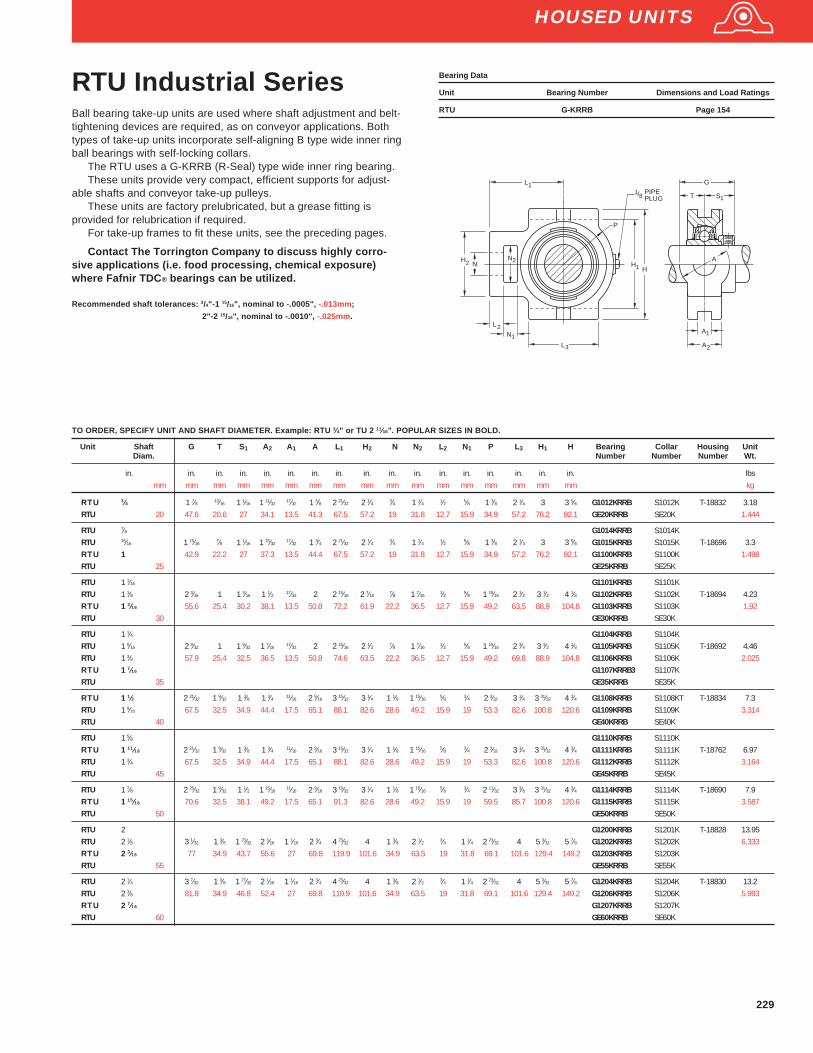
229
HOUSED UNITS
RTU Industrial SeriesBall bearing take-up units are used where shaft adjustment and belt-tightening devices are required, as on conveyor applications. Bothtypes of take-up units incorporate self-aligning B type wide inner ringball bearings with self-locking collars.
The RTU uses a G-KRRB (R-Seal) type wide inner ring bearing.These units provide very compact, efficient supports for adjust-
able shafts and conveyor take-up pulleys.These units are factory prelubricated, but a grease fitting is
provided for relubrication if required.For take-up frames to fit these units, see the preceding pages.
Contact The Torrington Company to discuss highly corro-sive applications (i.e. food processing, chemical exposure)where Fafnir TDC ® bearings can be utilized.
Recommended shaft tolerances: 3/4"-1 15/16", nominal to -.0005", -.013mm;
2"-2 15/16", nominal to -.0010", -.025mm.
Bearing Data
Unit Bearing Number Dimensions and Load Ratings
RTU G-KRRB Page 154
Unit Shaft G T S 1 A2 A1 A L1 H2 N N2 L2 N1 P L3 H1 H Bearing Collar Housing UnitDiam. Number Number Number Wt.
in. in. in. in. in. in. in. in. in. in. in. in. in. in. in. in. in. lbsmm mm mm mm mm mm mm mm mm mm mm mm mm mm mm mm mm kg
RTU 3⁄4 1 7⁄8 13⁄16 1 1⁄16 1 11⁄3217⁄32 1 5⁄8 2 21⁄32 2 1⁄4 3⁄4 1 1⁄4 1⁄2 5⁄8 1 3⁄8 2 1⁄4 3 3 5⁄8 G1012KRRB S1012K T-18832 3.18
RTU 20 47.6 20.6 27 34.1 13.5 41.3 67.5 57.2 19 31.8 12.7 15.9 34.9 57.2 76.2 92.1 GE20KRRB SE20K 1.444
RTU 7⁄8 G1014KRRB S1014KRTU 15⁄16 1 15⁄16
7⁄8 1 1⁄16 1 15⁄3217⁄32 1 3⁄4 2 21⁄32 2 1⁄4 3⁄4 1 1⁄4 1⁄2 5⁄8 1 3⁄8 2 1⁄4 3 3 5⁄8 G1015KRRB S1015K T-18696 3.3
RTU 1 42.9 22.2 27 37.3 13.5 44.4 67.5 57.2 19 31.8 12.7 15.9 34.9 57.2 76.2 92.1 G1100KRRB S1100K 1.498RTU 25 GE25KRRB SE25K
RTU 1 1⁄16 G1101KRRB S1101KRTU 1 1⁄8 2 3⁄16 1 1 3⁄16 1 1⁄2 17⁄32 2 2 15⁄16 2 7⁄16
7⁄8 1 7⁄161⁄2 5⁄8 1 15⁄16 2 1⁄2 3 1⁄2 4 1⁄8 G1102KRRB S1102K T-18694 4.23
RTU 1 3⁄16 55.6 25.4 30.2 38.1 13.5 50.8 72.2 61.9 22.2 36.5 12.7 15.9 49.2 63.5 88.9 104.8 G1103KRRB S1103K 1.92RTU 30 GE30KRRB SE30K
RTU 1 1⁄4 G1104KRRB S1104KRTU 1 5⁄16 2 9⁄32 1 1 9⁄32 1 7⁄16
17⁄32 2 2 15⁄16 2 1⁄2 7⁄8 1 7⁄161⁄2 5⁄8 1 15⁄16 2 3⁄4 3 1⁄2 4 1⁄8 G1105KRRB S1105K T-18692 4.46
RTU 1 3⁄8 57.9 25.4 32.5 36.5 13.5 50.8 74.6 63.5 22.2 36.5 12.7 15.9 49.2 69.8 88.9 104.8 G1106KRRB S1106K 2.025RTU 1 7⁄16 G1107KRRB3 S1107KRTU 35 GE35KRRB SE35K
RTU 1 1⁄2 2 21⁄32 1 9⁄32 1 3⁄8 1 3⁄4 11⁄16 2 9⁄16 3 15⁄32 3 1⁄4 1 1⁄8 1 15⁄165⁄8 3⁄4 2 3⁄32 3 1⁄4 3 31⁄32 4 3⁄4 G1108KRRB S1108KT T-18834 7.3
RTU 1 9⁄16 67.5 32.5 34.9 44.4 17.5 65.1 88.1 82.6 28.6 49.2 15.9 19 53.3 82.6 100.8 120.6 G1109KRRB S1109K 3.314RTU 40 GE40KRRB SE40K
RTU 1 5⁄8 G1110KRRB S1110KRTU 1 11⁄16 2 21⁄32 1 9⁄32 1 3⁄8 1 3⁄4 11⁄16 2 9⁄16 3 15⁄32 3 1⁄4 1 1⁄8 1 15⁄16
5⁄8 3⁄4 2 3⁄32 3 1⁄4 3 31⁄32 4 3⁄4 G1111KRRB S1111K T-18762 6.97RTU 1 3⁄4 67.5 32.5 34.9 44.4 17.5 65.1 88.1 82.6 28.6 49.2 15.9 19 53.3 82.6 100.8 120.6 G1112KRRB S1112K 3.164RTU 45 GE45KRRB SE45K
RTU 1 7⁄8 2 25⁄32 1 9⁄32 1 1⁄2 1 15⁄1611⁄16 2 9⁄16 3 19⁄32 3 1⁄4 1 1⁄8 1 15⁄16
5⁄8 3⁄4 2 11⁄32 3 3⁄8 3 31⁄32 4 3⁄4 G1114KRRB S1114K T-18690 7.9RTU 1 15⁄16 70.6 32.5 38.1 49.2 17.5 65.1 91.3 82.6 28.6 49.2 15.9 19 59.5 85.7 100.8 120.6 G1115KRRB S1115K 3.587RTU 50 GE50KRRB SE50K
RTU 2 G1200KRRB S1201K T-18828 13.95RTU 2 1⁄8 3 1⁄32 1 3⁄8 1 23⁄32 2 3⁄16 1 1⁄16 2 3⁄4 4 23⁄32 4 1 3⁄8 2 1⁄2 3⁄4 1 1⁄4 2 23⁄32 4 5 3⁄32 5 7⁄8 G1202KRRB S1202K 6.333RTU 2 3⁄16 77 34.9 43.7 55.6 27 69.8 119.9 101.6 34.9 63.5 19 31.8 69.1 101.6 129.4 149.2 G1203KRRB S1203KRTU 55 GE55KRRB SE55K
RTU 2 1⁄4 3 7⁄32 1 3⁄8 1 27⁄32 2 1⁄16 1 1⁄16 2 3⁄4 4 23⁄32 4 1 3⁄8 2 1⁄2 3⁄4 1 1⁄4 2 23⁄32 4 5 3⁄32 5 7⁄8 G1204KRRB S1204K T-18830 13.2RTU 2 3⁄8 81.8 34.9 46.8 52.4 27 69.8 119.9 101.6 34.9 63.5 19 31.8 69.1 101.6 129.4 149.2 G1206KRRB S1206K 5.993RTU 2 7⁄16 G1207KRRB S1207KRTU 60 GE60KRRB SE60K
TO ORDER, SPECIFY UNIT AND SHAFT DIAMETER. Example: RTU 3⁄4" or TU 2 11⁄16". POPULAR SIZES IN BOLD.
HH
HN
N
L
L
PIPEPLUG
18/
P
A
A
A
T S
G
L
N
1
22
1
2
1
3 2
1
1

230
Unit Shaft G T S 1 A2 A1 A L1 H2 N N2 L2 N1 P L3 H1 H Bearing HousingDiam. Number Number
in. in. in. in. in. in. in. in. in. in. in. in. in. in. in. in. in.mm mm mm mm mm mm mm mm mm mm mm mm mm mm mm mm mm
YTU 3⁄4 1 3⁄4 13⁄16 0.719 1 11⁄32 17⁄32 1 5⁄8 2 21⁄32 2 1⁄4 3⁄4 1 1⁄4 1⁄2 5⁄8 1 5⁄16 2 1⁄4 3 3 5⁄8 GY1012KRRB T-18832YTU 20 44.4 20.6 18.3 34.1 13.5 41.3 67.5 57.2 19 31.8 12.7 15.9 33.3 57.2 76.2 92.1 GYE20KRRB
YTU 7⁄8 GY1014KRRB T-18696YTU 15⁄16 1 15⁄16
7⁄8 0.781 1 15⁄3217⁄32 1 3⁄4 2 21⁄32 2 1⁄4 3⁄4 1 1⁄4 1⁄2 5⁄8 1 3⁄8 2 1⁄4 3 3 5⁄8 GY1015KRRB
YTU 1 49.2 22.2 19.8 37.3 13.5 44.4 67.5 57.2 19 31.8 12.7 15.9 34.9 57.2 76.2 92.1 GY1100KRRBYTU 25 GYE25KRRB
YTU 1 1⁄8 2 1⁄16 1 0.875 1 1⁄2 17⁄32 2 2 27⁄32 2 7⁄167⁄8 1 7⁄16
1⁄2 5⁄8 1 5⁄8 2 1⁄2 3 1⁄2 4 1⁄8 GY1102KRRB T-18694YTU 1 3⁄16 52 25.4 22.2 38.1 13.5 50.8 72.2 61.9 22.2 36.5 12.7 15.9 41.3 63.5 88.9 104.8 GY1103KRRBYTU 30 GYE30KRRB
YTU 1 1⁄4 2 5⁄32 1 1.017 1 7⁄1617⁄32 2 2 15⁄16 2 1⁄2 7⁄8 1 7⁄16
1⁄2 5⁄8 1 15⁄16 2 3⁄4 3 1⁄2 4 1⁄8 GY1104KRRB T-18692YTU 1 3⁄8 54.7 25.4 25.8 36.5 13.5 50.8 74.6 63.5 22.2 36.5 12.7 15.9 49.2 69.8 88.9 104.8 GY1106KRRBYTU 1 7⁄16 GY1107KRRB3YTU 35 GYE35KRRB
YTU 1 1⁄2 2 9⁄16 1 9⁄32 1.188 1 3⁄4 11⁄16 2 9⁄16 3 15⁄32 3 1⁄4 1 1⁄8 1 15⁄165⁄8 3⁄4 2 3⁄32 3 1⁄4 3 31⁄32 4 3⁄4 GY1108KRRB T-18834
YTU 40 65 32.5 30.2 44.4 17.5 65.1 88.1 82.6 28.6 49.2 15.9 19 53.3 82.6 100.8 120.6 GYE40KRRB
YTU 1 5⁄8 GY1110KRRBYTU 1 11⁄16 2 9⁄16 1 9⁄32 1.188 1 3⁄4 11⁄16 2 9⁄16 3 15⁄32 3 1⁄4 1 1⁄8 1 15⁄16
5⁄8 3⁄4 2 3⁄32 3 1⁄4 3 31⁄32 4 3⁄4 GY1111KRRB T-18762YTU 1 3⁄4 65 32.5 30.2 44.4 17.5 65.1 88.1 82.6 28.6 49.2 15.9 19 53.3 82.6 100.8 120.6 GY1112KRRBYTU 45 GYE45KRRB
YTU 1 15⁄16 2 9⁄16 1 9⁄32 1.281 1 15⁄1611⁄16 2 9⁄16 3 19⁄32 3 1⁄4 1 1⁄8 1 15⁄16
5⁄8 3⁄4 2 11⁄32 3 3⁄8 3 31⁄32 4 3⁄4 GY1115KRRB T-18690YTU 1 50 65 32.5 32.5 49.2 17.5 65.1 91.3 82.6 28.6 49.2 15.9 19 59.5 85.7 100.8 120.6 GYE50KRRB
YTU 2 3⁄16 2 13⁄16 1 3⁄8 1.312 2 3⁄16 1 1⁄16 2 3⁄4 4 23⁄32 4 1 3⁄8 2 1⁄2 3⁄4 1 1⁄4 2 23⁄32 4 5 3⁄32 5 7⁄8 GY1203KRRB T-18828YTU 55 71.4 34.9 33.3 55.6 27 69.8 119.9 101.6 34.9 63.5 19 31.8 69.1 101.6 129.4 149.2 GYE55KRRB
YTU 2 1⁄4 2 15⁄16 1 3⁄8 1.562 2 1⁄16 1 1⁄16 2 3⁄4 4 23⁄32 4 1 3⁄8 2 1⁄2 3⁄4 1 1⁄4 2 23⁄32 4 5 3⁄32 5 7⁄8 GY1204KRRB T-18830YTU 2 7⁄16 74.6 34.9 39.7 52.4 27 69.8 119.9 101.6 34.9 63.5 19 31.8 69.1 101.6 129.4 149.2 GY1207KRRB
TO ORDER, SPECIFY UNIT AND SHAFT DIAMETER. Example: YTU 3⁄4". POPULAR SIZES ARE IN BOLD.
A
A
A
T S
G
2
1
1
HH
HN
N
L
L
PIPEPLUG
18/
P
L
N
1
22
1
2
1
3
HOUSED UNITS
YTU Industrial SeriesBall bearing take-up units are used where shaft adjustment and belttightening devices are required, as on conveyor applications. YTUseries take-up units incorporate self-aligning B type extra wide innerring ball bearings with self-locking collars.
The YTU uses a GY-KRRB (Setscrew) type wide inner ringbearing.
These units provide very compact, efficient supports for adjustableshafts and conveyor take-up pulleys.
These units are factory prelubricated, but a grease fitting isprovided for relubrication if required.
For take-up frames to fit these units, see the preceding pages.
Contact The Torrington Company to discuss highly corrosiveapplications (i.e. food processing, chemical exposure) whereFafnir TDC ® bearings can be utilized.
Recommended shaft tolerances: 1/2"-1 15/16", nominal to -.0005", -.013mm;
2"-2 15/16", nominal to -.0010", -.025mm.
Bearing Data
Unit Bearing Number Dimensions and Load Ratings
YTU GY-KRRB Page 167
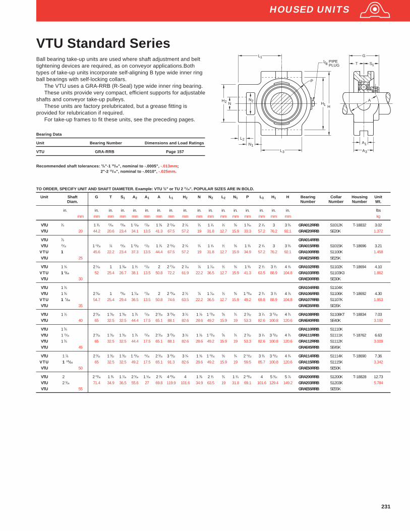
231
Unit Shaft G T S 1 A2 A1 A L1 H2 N N2 L2 N1 P L3 H1 H Bearing Collar Housing UnitDiam. Number Number Number Wt.
in. in. in. in. in. in. in. in. in. in. in. in. in. in. in. in. in. lbsmm mm mm mm mm mm mm mm mm mm mm mm mm mm mm mm mm kg
VTU 3⁄4 1 3⁄4 13⁄16 15⁄16 1 11⁄32 17⁄32 1 5⁄8 2 21⁄32 2 1⁄4 3⁄4 1 1⁄4 1⁄2 5⁄8 1 5⁄16 2 1⁄4 3 3 5⁄8 GRA012RRB S1012K T-18832 3.02VTU 20 44.2 20.6 23.4 34.1 13.5 41.3 67.5 57.2 19 31.8 12.7 15.9 33.3 57.2 76.2 92.1 GRAE20RRB SE20K 1.372
VTU 7⁄8 GRA014RRBVTU 15⁄16 1 13⁄16 7⁄8 15⁄16 1 15⁄32 17⁄32 1 3⁄4 2 21⁄32 2 1⁄4 3⁄4 1 1⁄4 1⁄2 5⁄8 1 3⁄8 2 1⁄4 3 3 5⁄8 GRA015RRB S1015K T-18696 3.21
VTU 1 45.6 22.2 23.4 37.3 13.5 44.4 67.5 57.2 19 31.8 12.7 15.9 34.9 57.2 76.2 92.1 GRA100RRB S1100K 1.458VTU 25 GRAE25RRB SE25K
VTU 1 1⁄8 2 1⁄16 1 1 3⁄64 1 1⁄2 17⁄32 2 2 27⁄32 2 7⁄167⁄8 1 7⁄16
1⁄2 5⁄8 1 5⁄8 2 1⁄2 3 1⁄2 4 1⁄8 GRA102RRB S1102K T-18694 4.10VTU 1 3⁄16 52 25.4 26.7 38.1 13.5 50.8 72.2 61.9 22.2 36.5 12.7 15.9 41.3 63.5 88.9 104.8 GRA103RRB S1103K3 1.862VTU 30 GRAE30RRB SE30K
VTU 1 1⁄4 GRA104RRB S1104KVTU 1 3⁄8 2 5⁄32 1 15⁄32 1 7⁄16
17⁄32 2 2 15⁄16 2 1⁄2 7⁄8 1 7⁄161⁄2 5⁄8 1 15⁄16 2 3⁄4 3 1⁄2 4 1⁄8 GRA106RRB S1106K T-18692 4.30
VTU 1 7⁄16 54.7 25.4 29.4 36.5 13.5 50.8 74.6 63.5 22.2 36.5 12.7 15.9 49.2 69.8 88.9 104.8 GRA107RRB S1107K 1.953VTU 35 GRAE35RRB SE35K
VTU 1 1⁄2 2 9⁄16 1 9⁄32 1 9⁄32 1 3⁄4 11⁄16 2 9⁄16 3 15⁄32 3 1⁄4 1 1⁄8 1 15⁄165⁄8 3⁄4 2 3⁄32 3 1⁄4 3 31⁄32 4 3⁄4 GRA108RRB S1108KT T-18834 7.03
VTU 40 65 32.5 32.5 44.4 17.5 65.1 88.1 82.6 28.6 49.2 15.9 19 53.3 82.6 100.8 120.6 GRAE40RRB SE40K 3.192
VTU 1 5⁄8 GRA110RRB S1110KVTU 1 11⁄16 2 9⁄16 1 9⁄32 1 9⁄32 1 3⁄4 11⁄16 2 9⁄16 3 15⁄32 3 1⁄4 1 1⁄8 1 15⁄16
5⁄8 3⁄4 2 3⁄32 3 1⁄4 3 31⁄32 4 3⁄4 GRA111RRB S1111K T-18762 6.63VTU 1 3⁄4 65 32.5 32.5 44.4 17.5 65.1 88.1 82.6 28.6 49.2 15.9 19 53.3 82.6 100.8 120.6 GRA112RRB S1112K 3.009VTU 45 GRAE45RRB SE45K
VTU 1 7⁄8 2 9⁄16 1 9⁄32 1 9⁄32 1 15⁄1611⁄16 2 9⁄16 3 19⁄32 3 1⁄4 1 1⁄8 1 15⁄16
5⁄8 3⁄4 2 11⁄32 3 3⁄8 3 31⁄32 4 3⁄4 GRA114RRB S1114K T-18690 7.36VTU 1 15⁄16 65 32.5 32.5 49.2 17.5 65.1 91.3 82.6 28.6 49.2 15.9 19 59.5 85.7 100.8 120.6 GRA115RRB S1115K 3.342VTU 50 GRAE50RRB SE50K
VTU 2 2 13⁄16 1 3⁄8 1 7⁄16 2 5⁄16 1 1⁄16 2 3⁄4 4 23⁄32 4 1 3⁄8 2 1⁄2 3⁄4 1 1⁄4 2 23⁄32 4 5 3⁄32 5 7⁄8 GRA200RRB S1200K T-18828 12.73VTU 2 3⁄16 71.4 34.9 36.5 55.6 27 69.8 119.9 101.6 34.9 63.5 19 31.8 69.1 101.6 129.4 149.2 GRA203RRB S1203K 5.784VTU 55 GRAE55RRB SE55K
TO ORDER, SPECIFY UNIT AND SHAFT DIAMETER. Example: VTU 3⁄4" or TU 2 11⁄16". POPULAR SIZES ARE IN BOLD.
VTU Standard SeriesBall bearing take-up units are used where shaft adjustment and belttightening devices are required, as on conveyor applications.Bothtypes of take-up units incorporate self-aligning B type wide inner ringball bearings with self-locking collars.
The VTU uses a GRA-RRB (R-Seal) type wide inner ring bearing.These units provide very compact, efficient supports for adjustable
shafts and conveyor take-up pulleys.These units are factory prelubricated, but a grease fitting is
provided for relubrication if required.For take-up frames to fit these units, see the preceding pages.
Bearing Data
Unit Bearing Number Dimensions and Load Ratings
VTU GRA-RRB Page 157
Recommended shaft tolerances: 3/4"-1 15/16", nominal to -.0005", -.013mm;2"-2 15/16", nominal to -.0010", -.025mm.
HH
HN
N
L
L
PIPEPLUG
18/
P
A
A
S
L
N
1
1
2
2
1
3
1
3
1
2 A
T
G
HOUSED UNITS
Thrust Bearings
Nomenclature
INTRODUCTION . . . . . . . . . . . . . . . . . . . . . . . . . . . . 322
BEARING TYPES . . . . . . . . . . . . . . . . . . . . . . 322-323
DIMENSIONS – LOAD RATINGS
Thrust Ball Type TVB . . . . . . . . . . . . . . . . . . . 324-325
Angular Contact Thrust Type TVL . . . . . . . . . 326-327
Angular Contact Thrust Type DTVL . . . . . . . . . . . . 328
Thrust Spherical Roller Type TSR . . . . . . . . . 329-330
Thrust Cylindrical Roller Type TP . . . . . . . . . 331-332
Thrust Cylindrical Roller Type TPS . . . . . . . . 333-334
Thrust Tapered Roller Type TTHD . . . . . . . . . 335-336
Thrust Tapered Roller Type TTVF . . . . . . . . . 337-338
Thrust Tapered Roller Type TTVS . . . . . . . . . . . . . . 339
Page

Thrust Bearings
From the three-digit “Series” number, it is knownthis is an inch size bearing. “50” is read as “5.0”and represents approximate or actual bore.
The series number (always three numerals)represents a specific size cage assembly.
50 TVB 190
TVB Thrust Ball BearingsTVL Angular Contact Thrust Ball Bearings
DTVL Angular Contact Thrust Ball Bearings –upper and lower complement of balls
TP Thrust Cylindrical Roller BearingsTPS Thrust Cylindrical Roller Bearings –
Two bottom washersTTHD Thrust Tapered Roller Bearings

322
THRUST BEARINGS
DTVL
TSR
TVL
TVB
INTRODUCTION
Four basic designs of thrust rolling bearings are available from Torrington: ball, spherical roller,cylindrical roller and tapered roller. Dimensional data for all styles are presented in order by bore size.
Engineering data such as tolerances, shaft and housing fits, and life and load rating calculations arefound in the Engineering section of this catalog.
Bearing TypesTHRUST BALL BEARINGSTorrington thrust ball bearings provide optimum performance in high speed installations, particularlywhere loads are generally lighter.
Two basic types of thrust ball bearings are available from Torrington, axial (TVB), and angularcontact (TVL). Torrington also offers a DTVL type, with both an upper and lower complement of angularcontact balls and three race elements.
Torrington standard tolerances for thrust ball bearings (both types) are equivalent to ABEC-1 whereapplicable, but higher precision tolerances are available. Consult a Torrington sales engineer aboutsuch installations.
TVBTorrington TVB thrust bearings are separable, and consist of two hardened and ground steel washers.The precision ground and lapped balls run in a grooved raceway, separated by a bronze cage. Othermaterials may be specified for the cage, depending on the application.
TVB ball thrust bearings provide axial rigidity, but are not recommended if radial loading is expected.TVB bearings are exceptionally easy to mount, with the rotating washer usually shaft mounted. The
stationary washer should be housed with an outside diameter clearance that allows the bearing toassume a normal operating position.
Most TVB bearings made by Torrington include washers of the same bore and outside diameter.Housings should therefore be designed to clear the O.D. of rotating washers, with shafts stepped toclear the bore of stationary washers.
TVLTorrington TVL angular-contact thrust ball bearings provide exceptionally low friction, cool running andquiet operation when operated at high speeds. They are also less sensitive to misalignment.
While TVL bearings have been designed exclusively for thrust loads, the angular contact design willaccommodate some radial loading. Consult a Torrington sales engineer for assistance in determiningthe limits of such loading for specific applications.
The hardened and ground steel races of TVL bearings enclose a complement of precision groundand lapped steel balls, separated by a bronze cage (other material may be specified as required ).
Although TVL is not strictly an annular ball bearing, the larger ring is identified as the outer ring; thesmaller as the inner. The inner ring is usually the rotating element and is shaft mounted. The outer ring,normally stationary, should be mounted with an outside diameter clearance that allows the bearing toassume a normal operating position.If combined loads are expected, the outer ring must be radiallylocated in the housing.
TVL bearings should always be operated under thrust loading, as will happen in the usual applica-tions for thrust ball bearings (oil field rotary tables or machine tool indexing tables). If a constant thrustload is not normally present, it should be imposed by springs or other devices.
DTVLThe DTVL has an upper and lower complement of angular contact balls and three race elements. Thisseries is capable of carrying thrust in one direction comparable to the TVL series and lighter thrust in theopposite direction.
THRUST SPHERICAL ROLLER BEARINGSTSRThe Torrington self-aligning thrust spherical roller bearing is a combination radial and thrust bearing,designed to operate even if shaft and housing are, or become, misaligned under load. This type ofheavy-duty bearing is the favored choice when conditions include heavy loads, plus difficulties inestablishing or maintaining housing alignment, or when shaft deflection can be expected.
Shaft deflections and housing distortions caused by shock or heavy loads ( which lead to misalign-ment ) are compensated for by the internal self-alignment of the bearing elements during operation.Corner loading of rollers, a condition that limits service life on other types of bearings, cannot develop inspherical roller thrust bearings.
Torrington spherical roller thrust bearings achieve high thrust capacity and allow axial misalignmentbetween the inner ring and the outer ring of up to ± 2.5°. Spherically contoured rollers, arranged in asteep angular position, not only accept high axial loads, but moderate radial loads as well. Torrington“E” styles (EM - machined bronze cage, EJ - stamped steel cage) have increased capacity. Shouldextreme conditions of loading and/or speed under misalignment be anticipated, Torrington engineersshould be consulted before ordering.

323
TTHD
TTVF
TPS
TP
TTVS
THRUST SPHERICAL ROLLER BEARINGS (continued)The inherent compensation for misalignment provided by the spherical roller bearing offers thedesigner the opportunity to use weldments for housing frames instead of complex castings, eliminat-ing high-cost machining operations. Even when castings may be preferred, bore alignment is lesscritical if spherical roller bearings are specified.
THRUST CYLINDRICAL ROLLER BEARINGSTorrington thrust cylindrical roller bearings have been designed to operate under heavy loads atmoderate speeds. Standard versions of these bearings can be operated at peripheral speeds(bearing O.D.) of up to 3000 feet per minute. Special Torrington design features are available for boththe bearing and mounting which will permit even higher rotational speeds for this type of bearing.Two types of cylindrical roller thrust bearings, TP and TPS, are available from Torrington.
TPTorrington TP thrust bearings have two flat hardened and ground steel washers with a cage retainerholding one or more Controlled-Contour rollers in each pocket. If specifications call for two or morerollers per pocket, they are manufactured to different lengths. The longer rollers are placed inalternate positions in adjacent pockets. The overlapping roller paths prevent “grooving” of thewashers and prolong bearing life. Because of the simplicity of their design, standard TP thrustbearings are among the most economical to buy and install. Minor radial displacement of the racesdoes not affect the operation of the TP bearing, resulting in manufacturing economies and simplifiedinstallation.
Shaft and housing seats must be square to the axis of rotation to prevent initial misalignmentproblems.
TPSThe Torrington TPS bearing is similar to the TP style, except that the bottom washer assembly iscomprised of two washers, with the contacting faces spherically ground. The TPS bearing is thusself-adjusting to initial misalignment. It is not, however, recommended for installations wherealignment may be continuously changing (dynamic misalignment).
THRUST TAPERED ROLLER BEARINGSTorrington true rolling thrust tapered roller bearings include rollers which have conical sections.These bearings have been engineered so that the rollers and raceways form a cone whose vertex ison the center line of the bearing. This bearing geometry assures a true rolling motion. In addition, thelarge end of each tapered roller is spherically ground so that its curvature matches the concave faceof the washer rib. Pressure between the rib and roller, under load, guides the rollers accurately.Torrington manufactures three types of thrust tapered roller bearings: standard (TTHD), V-Flat(TTVF) and self-aligning V-Flat (TTVS).
TTHDThe standard TTHD bearing has an identical pair of hardened and ground steel washers, withtapered raceways. Since both washers have the same bore and O.D., housings should be designedto clear the O.D. of rotating washers and shafts stepped to clear the bore of stationary washers. TheControlled-Contour tapered rollers are equally spaced by a cage.
TTHD bearings are well suited for applications where extremely high thrust loads and heavyshock may be encountered, such as in crane hooks. For very low speed applications with unusuallyhigh loading, Torrington TTHD bearings can be supplied with a full complement of rollers. Thesebearings are identified in the tables by the suffix 278 following the bearing number. Applications forfull-complement bearings should be reviewed with a Torrington sales engineer to assure selection ofthe proper bearing.
TTVF, TTVSV-Flat Tapered Roller bearings (TTVF and TTVS) combine the outstanding features of thrust taperedand cylindrical roller bearings to offer the highest possible capacity of any thrust bearing of its size. Inthe V-Flat design, one washer is flat, while the second has a tapered raceway matching the rollers.The design was originally developed for screwdown applications in metal rolling mills where thrustloads exceeding one million pounds are common.
Torrington V-Flat bearings have exceptional dynamic capacity within a given envelope andprovide superior static capacity.They have been highly successful in heavily loaded extruders, incone crushers and other applications where a wide range of operating conditions are found.Mostsizes of V-Flat bearings utilize cages with hardened pins through the center of the rollers. This allowscloser spacing of the rollers to maximize capacity. Smaller sizes have cast bronze cages, carefullymachined to permit full flow of lubricant. Self-aligning V-Flat bearings (TTVS) employs the samebasic roller and raceway design, except the lower washer is in two pieces, with the contacting facesspherically ground to permit self-alignment under conditions of initial misalignment.TTVS bearingsshould not be used, however, if dynamic misalignment (changing under load) is expected.
THRUST BEARINGS

324
THRUST BEARINGS
Thrust Ball BearingsType TVBType TVB thrust ball bearings are designed for optimum performancein high speed installations. They provide axial rigidity, but are notrecommended if radial loading is expected. Type TVB is exceptionallyeasy to mount, with the rotating washer usually shaft-mounted.
DIMENSIONS – LOAD RATINGSShoulder Diameter Load Rating
Bearing Bore O.D. Height Shaft Housing Fillet Radius(1)
Wt. Static Load Dynamic LoadNumber d D T H E r Rating Rating
(min.) (max.) (max.) C oa Ct
in. in. in. in. in. in. lbs. lbs. lbs.mm mm mm mm mm mm kg N N
50TVB190 5.0000 7.2500 1.6250 6.72 5.53 0.09 7.2 131000 38000127.000 184.150 41.275 170.7 140.5 2.4 3.4 583000 169000
52TVB253 5.2500 8.0000 2.0000 7.31 5.94 0.09 12.2 170000 50200133.350 203.200 50.800 185.7 150.8 2.4 5.5 756000 223000
55TVB245 5.5000 8.2500 1.8750 7.56 6.19 0.09 11.3 173000 52000139.700 209.550 47.625 192.1 157.2 2.4 5.1 770000 231000
57TVB248 5.7500 8.5000 1.8750 7.81 6.44 0.09 11.7 182000 53800146.050 215.900 47.625 198.4 163.5 2.4 5.3 810000 239000
60TVB252 6.0000 8.7500 1.8750 8.06 6.69 0.09 12.4 187000 53500152.400 222.250 47.625 204.8 169.9 2.4 5.6 832000 238000
62TVB291 6.2500 9.0000 1.8750 8.47 6.78 0.09 12.8 195000 55100158.750 228.600 47.625 215.1 172.2 2.4 5.8 867000 245000
65TVB293 6.5000 9.5000 2.2500 8.84 7.16 0.12 17.0 238000 71300165.100 241.300 57.150 224.6 181.8 3.2 7.7 1060000 317000
67TVB296 6.7500 9.7500 2.2500 9.03 7.47 0.12 17.5 251000 73800171.450 247.650 57.150 229.4 189.7 3.2 7.9 1110000 328000
70TVB298 7.0000 10.0000 2.2500 9.28 7.72 0.12 18.1 263000 76300177.800 254.000 57.150 235.7 196.1 3.2 8.2 1170000 339000
75TVB343 7.5000 10.5000 2.2500 9.84 8.16 0.12 20.0 255000 72300190.500 266.700 57.150 250 207.2 3.2 9.1 1140000 321000
75TVB344 7.5000 10.8750 2.7500 10.19 8.19 0.12 27.9 313000 91400190.500 276.225 69.850 258.8 208 3.2 12.7 1390000 407000
80TVB346 8.0000 11.0000 2.2500 10.34 8.66 0.12 19.3 309000 88900203.200 279.400 57.150 262.7 219.9 3.2 8.8 1370000 395000
(1) Maximum shaft or housing fillet radius which bearing corners will clear.
H
d
r
T
D
r
E
r

325
Thrust Ball BearingsType TVB
DIMENSIONS – LOAD RATINGSShoulder Diameter Load Rating
Bearing Bore O.D. Height Shaft Housing Fillet Radius(1)
Wt. Static Load Dynamic LoadNumber d D T H E r Rating Rating
(min.) (max.) (max.) C oa Ct
in. in. in. in. in. in. lbs. lbs. lbs.mm mm mm mm mm mm kg N N
80TVB347 8.0000 11.6250 3.0000 10.75 8.75 0.25 34.5 382000 113000203.200 295.275 76.200 273.1 222.2 6.4 15.6 1700000 504000
85TVB391 8.5000 11.5000 2.2500 10.84 9.16 0.12 22.2 289000 78400215.900 292.100 57.150 275.4 232.6 3.2 10.1 1280000 349000
90TVB393 9.0000 12.0000 2.2500 11.34 9.66 0.12 21.3 365000 99400228.600 304.800 57.150 288.1 245.3 3.2 9.7 1620000 442000
95TVB431 9.5000 12.5000 2.2500 11.84 10.16 0.12 24.4 311000 82400241.300 317.500 57.150 300.8 258 3.2 11.1 1380000 366000
100TVB433 10.0000 13.5000 2.2500 12.78 10.72 0.25 29.5 351000 96800254.000 342.900 57.150 324.6 272.3 6.4 13.4 1560000 431000
105TVB471 10.5000 14.0000 2.2500 13.28 11.22 0.25 30.7 407000 107000266.700 355.600 57.150 337.3 285 6.4 13.9 1810000 476000
110TVB472 11.0000 14.5000 2.2500 13.78 11.72 0.25 31.9 421000 109000279.400 368.300 57.150 350 297.7 6.4 14.5 1870000 486000
120TVB511 12.0000 15.5000 2.2500 14.78 12.72 0.25 34.5 450000 114000304.800 393.700 57.150 375.4 323.1 6.4 15.6 2000000 507000
130TVB551 13.0000 16.5000 2.5000 15.78 13.72 0.25 39.6 555000 141000330.200 419.100 63.500 400.8 348.5 6.4 18 2470000 627000
140TVB581 14.0000 17.5000 2.5000 16.78 14.72 0.25 42.3 590000 146000355.600 444.500 63.500 426.2 373.9 6.4 19.2 2620000 649000
150TVB610 15.0000 19.0000 2.5000 18.12 15.89 0.25 54.7 590000 146000381.000 482.600 63.500 460.4 403.6 6.4 24.8 2620000 649000
160TVB640 16.0000 20.0000 2.5000 19.00 17.00 0.25 57.9 624000 152000406.400 508.000 63.500 482.6 431.8 6.4 26.3 2780000 677000
(1) Maximum shaft or housing fillet radius which bearing corners will clear.
THRUST BEARINGS

326
THRUST BEARINGS
Angular ContactThrust Ball BearingsType TVLType TVL angular contact thrust ball bearings provide exceptionally lowfriction, cool running and quiet operation when run at high speeds.
Although designed exclusively for thrust loads, Type TVL willaccommodate some radial loading.
DIMENSIONS – LOAD RATINGS(2)
Washers Shoulder Diam. Dowel Pin (one per Washer) Load Rating
Bearing Bore O.D. Height Small Large Shaft Housing Pin Hole Location Fillet(1)
Weight Static DynamicNumber d D T Diameter Bore H E Diameter from Centerline Radius Load Load
O.D I.D Small Large r Rating RatingD1 d1 Bore Bore
(min.) (max.) Washer Washer (max.) C oa Ct
in. in. in. in. in. in. in. in. in. in. in. lbs lbs lbsmm mm mm mm mm mm mm mm mm mm mm kg. N N
90TVL710 9.0000 11.6250 1.5000 10.938 9.688 10.31 10.31 — — — 0.12 13.6 143000 36900228.600 295.275 38.100 277.81 246.06 261.9 261.9 — — — 3.2 6.2 636000 164000
120TVL700 12.0000 16.0000 2.2500 14.500 13.500 14.00 14.00 0.375 6.50 7.50 0.12 40.8 359000 96400304.800 406.400 57.150 368.30 342.90 355.6 355.6 9.52 165.1 190.5 3.2 18.5 1600000 429000
150TVL701 15.0000 20.5000 3.3120 19.000 16.500 17.75 17.75 0.500 8.12 9.62 0.19 110.7 606000 162000381.000 520.700 84.125 482.60 419.10 450.8 450.8 12.70 206.4 244.5 4.8 50.2 2700000 721000
170TVL500 17.0000 25.0000 3.5000 22.250 19.250 21.00 21.00 0.500 9.25 11.75 0.31 197.5 986000 254000431.800 635.000 88.900 565.15 488.95 533.4 533.4 12.70 235 298.4 7.9 89.6 4390000 1130000
180TVL605 18.0000 24.6250 3.6250 21.625 20.000 21.31 21.31 0.625 9.75 11.25 0.12 172.9 1076000 288000457.200 625.475 92.075 549.28 508 541.3 541.3 15.88 247.6 285.8 3.2 78.4 4790000 1280000
195TVL470 19.5000 23.0000 2.2500 22.500 20.000 21.25 21.25 0.375 10.19 11.06 0.12 62.7 585000 134000495.300 584.200 57.150 571.50 508 539.8 539.8 9.52 258.8 281 3.2 28.4 2600000 596000
200TVL850 20.0000 27.7500 4.6250 24.750 22.250 23.88 23.88 0.625 10.88 13.00 0.25 280.7 1160000 303000508.000 704.850 117.475 628.68 565.15 606.4 606.4 15.88 276.2 330.2 6.4 127.3 5160000 1350000
201TVL615 20.1250 24.7500 2.6250 23.250 21.625 22.44 22.44 0.500 10.56 11.81 0.12 92.3 746000 177000511.175 628.650 66.675 590.55 549.28 569.9 569.9 12.70 268.3 300 3.2 41.9 3320000 787000
202TVL620 20.5000 27.7500 4.5000 24.500 22.500 24.00 24.00 0.812 11.00 12.88 0.25 269.7 1330000 351000514.350 704.850 114.300 622.30 571.50 609.6 609.6 20.64 279.4 327 6.4 122.3 5910000 1560000
227TVL302 22.7500 30.5000 4.6250 27.750 24.500 26.62 26.62 0.812 12.25 14.38 0.25 330.2 1490000 379000577.850 774.700 117.475 704.85 622.30 676.3 676.3 20.64 311.2 365.1 6.4 149.8 6620000 1690000
233TVL303 23.3750 31.1250 4.6250 28.375 25.625 27.25 27.25 0.875 12.62 14.56 0.25 332.2 1540000 388000593.725 790.575 117.475 720.72 650.88 692.2 692.2 22.22 320.7 369.9 6.4 150.7 6850000 1730000
238TVL304 23.8750 33.3750 5.2500 29.125 27.125 28.62 28.62 0.875 12.88 15.62 0.25 468.7 1910000 494000606.425 847.725 133.350 739.78 688.98 727.1 727.1 22.22 327 396.9 6.4 212.6 8510000 2200000
245TVL716 24.5000 30.2500 3.2500 28.875 26.790 27.38 27.38 0.500 12.75 14.62 0.12 168.0 861000 194000622.300 768.350 82.550 733.42 680.47 695.3 695.3 12.70 323.8 371.5 3.2 76.2 3830000 863000
245TVL612 24.5000 32.7500 4.6250 29.250 26.750 28.62 28.62 0.625 13.00 15.62 0.25 362.7 1590000 397000622.300 831.850 117.475 742.95 679.45 727.1 727.1 15.88 330.2 396.9 6.4 164.5 7070000 1770000
(1) Maximum shaft or housing fillet radius which bearing corners will clear.
(2) See Engineering section page E59 for application of Equivalent Thrust Load Factors: X = 0.76, Y = 1.00, T (min) = 1.56. [T ]R R is Thrust Load ÷ Radial Load
D1
H
d
rd1
E
D
T
r

327
Angular ContactThrust Ball BearingsType TVL(continued)
DIMENSIONS – LOAD RATINGS(2)
Washers Shoulder Diam. Dowel Pin (one per Washer) Load Rating
Bearing Bore O.D. Height Small Large Shaft Housing Pin Hole Location Fillet(1)
Weight Static DynamicNumber d D T Diameter Bore H E Diameter from Centerline Radius Load Load
O.D I.D Small Large r Rating RatingD1 d1 Bore Bore
(min.) (max.) Washer Washer (max.) C oa Ct
in. in. in. in. in. in. in. in. in. in. in. lbs lbs lbsmm mm mm mm mm mm mm mm mm mm mm kg. N N
252TVL505 25.2500 31.2500 3.5000 29.375 27.875 28.25 28.25 0.500 13.50 14.81 0.25 197.0 1220000 293000641.350 793.750 88.900 746.12 708.02 717.6 717.6 12.70 342.9 376.2 6.4 89.3 5430000 1300000
260TVL635 26.0000 35.2500 5.2500 31.125 28.625 30.62 30.62 0.812 14.00 16.62 0.25 500.4 2140000 533000660.400 895.350 133.350 790.58 727.08 777.9 777.9 20.64 355.6 422.3 6.4 226.9 9520000 2370000
302TVL510 30.2500 36.2500 3.5000 34.375 32.875 33.25 33.25 0.500 16.06 17.31 0.25 231.9 1430000 325000768.350 920.750 88.900 873.12 835.02 844.6 844.6 12.70 408 439.7 6.4 105.2 6360000 1450000
302TVL624 30.2500 39.6250 5.5000 35.500 33.000 34.94 34.94 0.875 16.12 18.75 0.25 597.8 2370000 570000768.350 1006.475 139.700 901.7 838.2 887.4 887.4 22.22 409.6 476.2 6.4 271.1 10600000 2540000
303TVL706 30.3750 35.3750 2.5000 33.875 31.875 32.88 32.88 0.500 15.88 17.00 0.25 128.0 877000 175000771.525 898.525 63.500 860.42 809.62 835 835 12.70 403.2 431.8 6.4 58 3900000 7788000
309TVL707 30.9375 37.5000 3.7500 34.750 33.750 34.25 34.25 0.625 16.38 17.88 0.25 260.0 952000 248000785.812 952.500 95.250 882.65 857.25 870 870 15.88 415.9 454 6.4 117.9 4230000 1100000
310TVL625 31.0000 40.3750 5.5000 36.125 35.188 35.69 35.69 0.875 16.62 19.12 0.25 581.0 2450000 582000787.400 1025.525 139.700 917.58 893.76 906.5 906.5 22.22 422.3 485.8 6.4 263.5 10900000 2590000
317TVL307 31.7500 40.3750 5.0000 36.750 34.375 36.00 36.00 0.875 16.81 18.75 0.25 530.6 2450000 582000806.450 1025.525 127.000 933.45 873.12 914.4 914.4 22.22 427 476.2 6.4 240.6 10900000 2590000
402TVL717 40.2500 46.5000 3.5000 44.625 42.125 43.38 43.38 0.750 20.88 22.50 0.25 326.0 1840000 3840001022.350 1181.100 88.900 1133.48 1069.98 1101.7 1101.7 19.05 530.2 571.5 6.4 147.8 8180000 1710000
410TVL718 41.0000 49.6250 5.0000 46.812 43.812 45.31 45.31 0.750 21.44 23.88 0.25 681.0 3140000 6870001041.400 1260.475 127.000 1189.04 1112.84 1150.9 1150.9 19.05 544.5 606.4 6.4 308.8 14000000 3060000
420TVL721 42.0000 50.6250 5.0000 47.812 44.812 46.31 46.31 0.875 22.06 24.25 0.25 695.0 3140000 6870001066.800 1285.875 127.000 1214.44 1138.24 1176.3 1176.3 22.22 560.4 616 6.4 315.2 14000000 3060000
530TVL719 53.0000 59.7500 4.1250 57.375 55.375 56.38 56.38 0.875 27.38 28.88 0.25 507.0 2040000 4120001346.200 1517.650 104.775 1457.32 1406.52 1431.9 1431.9 22.22 695.3 733.4 6.4 229.99 9080000 1830000
540TVL720 54.0000 63.7500 5.5000 60.375 57.375 58.88 58.88 0.875 28.12 30.75 0.25 1059.0 4060000 8150001371.600 1619.250 139.700 1533.52 1457.32 1495.4 1495.4 22.22 714.4 781 6.4 480.3 18000000 3630000
(1) Maximum shaft or housing fillet radius which bearing corners will clear.
(2) See Engineering section page E59 for application of Equivalent Thrust Load Factors: X = 0.76, Y = 1.00, T (min) = 1.56. [T ]R R is Thrust Load ÷ Radial Load
THRUST BEARINGS

328
THRUST BEARINGS
Angular Contact ThrustBall Bearings Type DTVLType DTVL angular contact thrust ball bearings are capable of carryingthrust in one direction, plus a lighter thrust in the opposite direction.
They are designed with an upper and lower complement of angularcontact balls and three race elements.
Check for availability.
dr
E
E
D
1
r
T
D1
D2
d1
T1
DIMENSIONS – LOAD RATINGS(2)
Bearing Bore Upper Race Lower Race Load RatingNumber
Upper Lower O.D. Height O.D. Shoulder O.D. Shoulder Weight Upper Lower
d d1 D T D1 D2 E E1 T1 Fillet(1)
Static Dynamic StaticRadius Load Load Load
r Rating Rating Rating(max.) Coa Ct Coa
in. in. in. in. in. in. in. in. in. in. lbs lbs lbs lbsmm mm mm mm mm mm mm mm mm mm kg. N N N
200DTVL722 20.0000 20.0000 29.2500 6.7500 26.750 24.250 23.125 22.00 5.000 0.25 391.0 1200000 351000 519000508.000 508.000 742.95 171.45 679.45 616 587.38 558.8 127.000 6.4 177.3 5340000 1560000 2310000
202DTVL723 20.2500 20.1250 27.7500 6.2500 24.500 24.000 23.250 22.44 4.50 0.25 294.0 1220000 332000 844000514.350 511.175 704.85 158.75 622.30 609.60 590.55 569.9 114.3 6.4 133.3 5430000 1480000 3750000
235DTVL724 23.5000 23.2500 33.0000 7.2500 30.500 28.000 26.625 25.50 5.50 0.25 543.0 1700000 443000 822000596.900 590.550 838.2 184.15 774.70 711.20 676.28 647.7 139.7 6.4 246.2 7560000 1970000 3660000
245DTVL725 24.5000 24.3750 32.1250 6.2500 28.750 28.250 27.500 26.68 4.50 0.25 347.0 1440000 369000 995000622.300 619.125 815.975 158.75 730.25 717.60 698.50 677.9 114.3 6.4 157.4 6410000 1640000 4430000
266DTVL726 26.6250 26.5000 36.0000 7.6250 34.500 31.000 31.00 29.25 5.625 0.25 654.0 1910000 558000 1420000676.275 673.100 914.4 193.675 876.30 787.40 787.4 743 142.88 6.4 296.6 8510000 2480000 6320000
305DTVL727 30.5000 30.2500 38.2500 6.2500 34.875 34.380 33.38 32.56 4.50 0.25 429.0 1750000 423000 1210000774.700 768.350 971.55 158.75 885.82 873.10 847.72 827.1 114.3 6.4 194.6 7780000 1880000 5390000
312DTVL728 31.2500 31.0000 39.6250 7.8750 39.375 35.250 35.50 34.00 5.50 0.25 717.0 2300000 557000 1620000793.750 787.400 1006.475 200.025 1000.12 895.40 901.7 863.6 139.7 6.4 325.2 10200000 2480000 7200000
405DTVL729 40.5000 40.3750 48.5000 6.2500 45.000 44.500 43.50 42.69 4.50 0.25 561.0 2280000 504000 14700001028.700 1025.525 1231.9 158.75 1143 1130.30 1104.9 1084.3 114.3 6.4 254.4 10200000 2240000 6540000
412DTVL730 41.2500 41.0000 49.6250 7.8750 49.375 45.250 45.50 44.00 5.50 0.25 920.0 2760000 625000 18500001047.750 1041.400 1260.475 200.025 1254.12 1149.40 1155.7 1117.6 139.7 6.4 417.2 12300000 2780000 8230000
541DTVL731 54.1250 54.0000 62.8750 9.7500 60.500 58.310 58.625 57.00 6.625 0.25 1443.0 3980000 804000 25000001374.775 1371.600 1597.025 247.65 1536.70 1481.10 1489.08 1447.8 168.28 6.4 654.4 17700000 3580000 11100000
(1) Maximum shaft or housing fillet radius which bearing corners will clear.
(2) See Engineering section page E59 for application of Equivalent Thrust Load Factors: X = 0.76, Y = 1.00, T (min) = 1.56. [T ]R R is Thrust Load ÷ Radial Load

329
Thrust SphericalRoller BearingsType TSRType TSR thrust spherical roller bearing design achieves a high thrustcapacity with low friction and continuous roller alignment. Sphericallycontoured rollers, arranged in steep angular position, not onlyaccomodate high thrust loads but support moderate radial loads aswell. The low friction of this bearing results from a combination ofbearing geometry and manufacturing technology.
DIMENSIONS – LOAD RATINGSShoulder Diameter Inner Ring Load Rating
Bearing Bore O.D. Height O.D. Assembly Pilot Outer Fillet (1)
Wt. Static Dynamic Approx.Number d D T d 1 H D1 Height Height Ring S Radius Load Load Limiting k
(2)
Shaft Housing T 1 T2 Height r Rating Rating Speed(min.) (max.) T 3 (max.) Coa Ct (for Oil
BathOnly)
in. in. in. in. in. in. in. in. in. in. in. lbs lbs lbsmm mm mm mm mm mm mm mm mm mm mm kg. N N rpm
29422 4.3307 9.0551 2.8740 6.378 6.496 8.661 2.717 1.024 1.378 2.717 0.10 33.4 260000 176000 1500 30110 230 73 162 165 220 69 26 35 69 2.5 15.2 1150000 800000
29424 4.7244 9.8425 3.0709 6.850 7.087 9.291 2.913 1.142 1.476 2.933 0.12 40.7 256000 216000 1350 40120 250 78 174 180 236 74 29 37 74 3.0 18.5 1180000 965000
29326 5.1181 8.8583 2.2835 6.744 6.963 8.465 2.165 0.748 1.130 2.972 0.08 21.6 197000 132000 1700 22130 225 58 171 177 215 55 19 29 75 2.0 9.8 880000 600000
29426 5.1181 10.6299 3.3464 7.375 7.677 10.039 3.189 1.220 1.669 3.189 0.12 52.6 388000 253000 1250 60130 270 85 187 195 255 81 31 42 81 3.0 23.9 1730000 1120000
29330 5.9055 9.8425 2.3622 7.638 7.677 9.449 2.244 0.787 1.142 3.425 0.08 27.5 255000 150000 1550 30150 250 60 194 195 240 57 20 29 87 2.0 12.5 1140000 670000
29430 5.9055 11.8110 3.5433 8.405 8.661 11.220 3.386 1.260 1.732 3.622 0.12 64.5 440000 275000 1100 80150 300 90 213 220 285 86 32 44 92 3.0 29.3 1930000 1220000
29334 6.6929 11.0236 2.6378 8.504 8.661 10.630 2.520 0.906 1.280 3.780 0.10 36.3 340000 196000 1350 50170 280 67 216 220 270 64 23 32 96 2.5 16.5 1500000 880000
29434 6.6929 13.3858 4.0551 9.567 9.646 12.756 3.898 1.457 1.968 4.094 0.16 93.5 600000 365000 950 140170 340 103 243 245 324 99 37 50 104 4.0 42.4 2650000 1630000
29338EJ 7.4803 12.5984 3.0709 9.685 9.843 12.126 2.913 1.063 1.496 4.331 0.12 56.5 549000 333000 1150 80190 320 78 246 250 308 74 27 38 110 3.0 25.6 2442000 1481000
29438EJ 7.4803 14.9606 4.5276 10.669 10.827 14.173 4.370 1.614 2.185 4.606 0.16 133.0 937000 558000 850 210190 380 115 271 275 360 111 41 55 117 4.0 60.3 4168000 2482000
29340 7.8740 13.3858 3.3465 10.3937 10.4331 12.7953 3.4252 1.1417 1.5748 4.4882 .12 63 485000 278000 950 100200 340 85 264 265 325 81 29 40 114 3.0 29 2157000 1236000
29440 7.8740 15.7480 4.8031 11.254 11.417 14.961 4.606 1.693 2.323 4.803 0.16 154.0 815000 480000 800 260200 400 122 286 290 380 117 43 59 122 4.0 69.8 3625000 2135000
29344 8.6614 14.1732 3.3464 11.024 11.220 13.583 3.189 1.142 1.614 4.921 0.12 74.8 550000 300000 1000 120220 360 85 280 285 345 81 29 41 125 3.0 33.9 2500000 1340000
29444 8.6614 16.5354 4.8031 12.106 12.205 15.748 4.606 1.693 2.323 5.236 0.20 163.0 865000 500000 750 300220 420 122 307 310 400 117 43 59 133 5.1 73.9 3800000 2200000
29348 9.4488 14.9606 3.3464 11.811 11.811 14.370 3.189 1.142 1.614 5.315 0.12 92.4 600000 315000 950 140240 380 85 300 300 365 81 29 41 135 3.0 41.9 2650000 1400000
29448EM 9.4488 17.3228 4.8031 12.4016 12.6772 15.1575 3.4252 1.8110 2.4016 5.5906 24 171 1098000 615000 750 350240 440 122 315 322 385 87 46 61 142 6.1 78 4884000 2736000
29352 10.2362 16.5354 3.7402 12.953 12.992 15.945 3.583 1.260 1.791 5.827 0.16 113.0 750000 400000 850 230260 420 95 329 330 405 91 32 45 148 4.0 51.2 3350000 1800000
(1) Maximum shaft or housing fillet radius which bearing corners will clear.
(2) Centrifugal force constant. See Engineering section page E59 for calculations using this factor.
Continued on the next page.
D1
H
d
D
r
S
T
r
T2
T1 T3
d1
THRUST BEARINGS
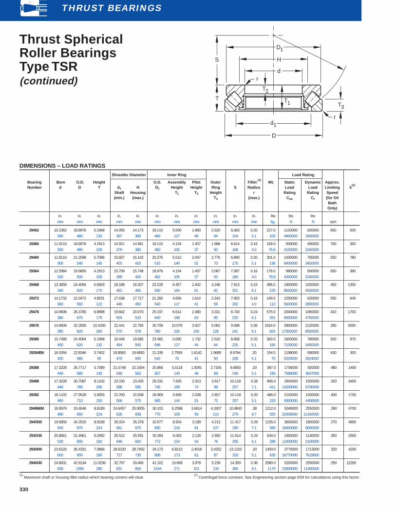
330
THRUST BEARINGS
Thrust SphericalRoller BearingsType TSR(continued)
DIMENSIONS – LOAD RATINGSShoulder Diameter Inner Ring Load Rating
Bearing Bore O.D. Height O.D. Assembly Pilot Outer Fillet (1)
Wt. Static Dynamic Approx.Number d D T d 1 H D1 Height Height Ring S Radius Load Load Limiting k
(2)
Shaft Housing T 1 T2 Height r Rating Rating Speed(min.) (max.) T 3 (max.) Coa Ct (for Oil
BathOnly)
in. in. in. in. in. in. in. in. in. in. in. lbs lbs lbsmm mm mm mm mm mm mm mm mm mm mm kg. N N rpm
29452 10.2362 18.8976 5.1968 14.055 14.173 18.110 5.000 1.890 2.520 6.063 0.20 227.0 1120000 620000 650 500260 480 132 357 360 460 127 48 64 154 5.1 103 4900000 1800000
29360 11.8110 18.8976 4.2913 14.921 14.961 18.110 4.134 1.457 1.988 6.614 0.16 169.0 930000 490000 700 350300 480 109 379 380 460 105 37 50 168 4.0 76.6 4150000 2160000
29460 11.8110 21.2598 5.7086 15.827 16.142 20.276 5.512 2.047 2.776 6.890 0.20 301.0 1430000 765000 550 780300 540 145 402 410 515 140 52 70 175 5.1 136 6400000 3450000
29364 12.5984 19.6850 4.2913 15.709 15.748 18.976 4.134 1.457 2.087 7.087 0.16 176.0 980000 500000 650 380320 500 109 399 400 482 105 37 53 180 4.0 79.8 4300000 2240000
29468 13.3858 24.4094 6.6929 18.189 18.307 23.228 6.457 2.402 3.248 7.913 0.24 486.0 1900000 1020000 450 1350340 620 170 462 465 590 164 61 82 201 6.1 220 8500000 4500000
29372 14.1732 22.0472 4.8031 17.638 17.717 21.260 4.606 1.614 2.343 7.953 0.16 249.0 1250000 620000 550 640360 560 122 448 450 540 117 41 59 202 4.0 113 5600000 2800000
29476 14.9606 26.3780 6.8898 19.842 20.079 25.197 6.614 2.480 3.331 8.740 0.24 575.0 2040000 1060000 410 1700380 670 175 504 510 640 168 63 85 220 6.1 261 9000000 4750000
29576 14.9606 32.2835 10.4330 22.441 22.756 30.709 10.078 3.927 5.062 9.488 0.36 1816.0 3900000 2120000 280 5550380 820 265 570 578 780 226 100 128 241 9.1 824 17300000 9500000
29380 15.7480 24.4094 5.1968 19.449 19.685 23.465 5.000 1.732 2.520 8.858 0.20 363.0 1600000 780000 500 970400 620 132 494 500 596 127 44 64 225 5.1 165 7100000 3450000
29284EM 16.5354 22.8346 3.7402 18.8583 19.6850 21.339 2.7559 1.6142 1.9685 8.9764 .20 154.0 1198000 590000 630 300420 580 95 479 500 542 70 41 50 228 5.1 70 5329000 2624000
29388 17.3228 26.7717 5.7089 21.5748 22.1654 25.866 5.5118 1.9291 2.7165 9.6850 .20 397.0 1706000 820000 480 1400440 680 145 548 563 657 140 49 69 246 5.1 180 7588000 3647000
29488 17.3228 30.7087 8.1102 23.150 23.425 29.331 7.835 2.913 3.917 10.118 0.28 906.0 2900000 1500000 320 3400440 780 206 588 595 745 199 74 99 257 7.1 411 13200000 6700000
29392 18.1102 27.9528 5.9055 22.293 22.638 26.969 5.669 2.008 2.857 10.118 0.20 486.0 2100000 1000000 400 1700460 710 150 566 575 685 144 51 72 257 5.1 220 9300000 4400000
29496EM 18.8976 33.4646 8.8189 24.6457 25.9055 30.315 6.2598 3.6614 4.3307 10.9843 .38 1212.0 5049000 2550000 290 4700480 850 224 626 658 770 159 93 110 279 9.7 550 22458000 11342000
294/500 19.6850 34.2520 8.8189 26.024 26.378 32.677 8.504 3.189 4.213 11.417 0.28 1235.0 3600000 1800000 270 4800500 870 224 661 670 830 216 81 107 290 7.1 560 16000000 8000000
293/530 20.8661 31.4961 6.2992 25.512 25.591 30.394 6.063 2.126 2.992 11.614 0.24 634.0 2450000 1140000 350 2500530 800 160 648 650 772 154 54 76 295 6.1 288 11000000 5100000
293/600 23.6220 35.4331 7.0866 28.6220 28.7402 34.173 6.8110 2.4016 3.4252 13.1102 .20 1400.0 3770000 1713000 320 4200600 900 180 727 730 868 173 61 87 333 5.1 635 16770000 7619000
294/630 24.8031 42.9134 11.0236 32.707 33.465 41.102 10.669 3.976 5.236 14.393 0.36 2580.0 5200000 2550000 250 12200630 1090 280 831 850 1044 271 101 133 365 9.1 1170 23000000 11400000
(1) Maximum shaft or housing fillet radius which bearing corners will clear.
(2) Centrifugal force constant. See Engineering section page E59 for calculations using this factor.
D1
H
d
D
r
S
T
r
T2
T1 T3
d1

331
Thrust CylindricalRoller BearingsType TPThe design simplicity of the standard Type TP thrust cylindrical rollerbearing makes it among the most economical to buy and install.
Minor radial displacement of the races does not affect its operation,resulting in manufacturing economies and simplified installation.
DIMENSIONS – LOAD RATINGSWashers Shoulder Diameter Load Rating
Bearing Bore O.D. Height Thickness Small Large Shaft Housing Fillet(1)
Wt. Static DynamicNumber d D T T 1 Diameter Bore H E Radius Load Load
O.D. I.D. r Rating RatingD1 d1 (min.) (max.) (max.) C oa Ct
in. in. in. in. in. in. in. in. in. lbs lbs lbsmm mm mm mm mm mm mm mm mm kg N N
20TP103 2.0000 6.0000 1.3750 0.375 5.938 2.062 5.56 2.44 0.06 8.1 183000 7450050.800 152.400 34.925 9.52 150.81 52.39 141.3 61.9 1.6 3.7 814000 331000
20TP104 2.0000 7.0000 1.3750 0.375 6.938 2.062 6.44 2.56 0.06 11.3 227000 8950050.800 177.800 34.925 9.52 176.21 52.39 163.5 65.1 1.6 5.1 1010000 398000
30TP106 3.0000 6.0000 1.3750 0.375 5.938 3.062 5.62 3.38 0.06 7.0 168000 7650076.200 152.400 34.925 9.52 150.81 77.79 142.9 85.7 1.6 3.2 747000 340000
30TP107 3.0000 7.0000 1.3750 0.375 6.938 3.062 6.56 3.44 0.06 10.2 234000 9320076.200 177.800 34.925 9.52 176.21 77.79 166.7 87.3 1.6 4.6 1040000 414000
30TP108 3.0000 8.0000 1.3750 0.375 7.938 3.062 7.44 3.56 0.06 13.9 311000 11700076.200 203.200 34.925 9.52 201.61 77.79 188.9 90.5 1.6 6.3 1380000 520000
30TP109 3.0000 9.0000 1.3750 0.375 8.938 3.062 8.38 3.62 0.06 18.1 405000 14300076.200 228.600 34.925 9.52 227.01 77.79 212.7 92.1 1.6 8.2 1800000 636000
35TP113 3.5000 5.2188 1.0000 0.281 5.156 3.562 4.88 3.84 0.06 3.0 85600 4040088.900 132.558 25.400 7.14 130.97 90.49 123.8 97.6 1.6 1.4 381000 180000
40TP114 4.0000 7.0000 1.7500 0.500 6.938 4.062 6.62 4.38 0.06 11.0 231000 113000101.600 177.800 44.450 12.7 176.21 103.19 168.3 111.1 1.6 5 1030000 503000
40TP115 4.0000 8.0000 1.7500 0.500 7.938 4.062 7.50 4.50 0.06 15.6 308000 132000101.600 203.200 44.450 12.7 201.61 103.19 190.5 114.3 1.6 7.1 1370000 589000
40TP116 4.0000 9.0000 1.7500 0.500 8.938 4.062 8.44 4.56 0.06 21.0 397000 152000101.600 228.600 44.450 12.7 227.01 103.19 214.3 115.9 1.6 9.5 1770000 676000
40TP117 4.0000 10.0000 1.7500 0.500 9.938 4.062 9.38 4.62 0.06 25.6 498000 202000101.600 254 44.450 12.7 252.41 103.19 238.1 117.5 1.6 11.6 2220000 896000
50TP119 5.0000 8.0000 1.7500 0.500 7.938 5.062 7.50 5.50 0.06 13.1 288000 133000127 203.200 44.450 12.7 201.61 128.59 190.5 139.7 1.6 5.9 1280000 593000
50TP120 5.0000 9.0000 1.7500 0.500 8.938 5.062 8.50 5.50 0.06 18.4 385000 161000127 228.600 44.450 12.7 227.01 128.59 215.9 139.7 1.6 8.3 1710000 716000
50TP121 5.0000 10.0000 2.0000 0.562 9.938 5.062 9.44 5.56 0.12 27.4 491000 189000127 254 50.800 14.29 252.41 128.59 239.7 141.3 3.2 12.4 2180000 841000
50TP122 5.0000 11.0000 2.0000 0.562 10.938 5.062 10.31 5.69 0.12 34.8 620000 224000127 279.400 50.800 14.29 277.81 128.59 261.9 144.5 3.2 15.8 2760000 996000
50TP123 5.0000 12.0000 2.0000 0.562 11.938 5.062 11.38 5.75 0.12 42.8 789000 262000127 304.800 50.800 14.29 303.21 128.59 288.9 146 3.2 19.4 3290000 1170000
60TP124 6.0000 9.0000 2.0000 0.562 8.938 6.062 8.56 6.44 0.12 16.8 317000 135000152.400 228.600 50.800 14.29 227.01 153.99 217.5 163.5 3.2 7.6 1410000 600000
60TP125 6.0000 10.0000 2.0000 0.562 9.938 6.062 9.50 6.50 0.12 23.7 449000 190000152.400 254 50.800 14.29 252.41 153.99 241.3 165.1 3.2 10.7 2000000 845000
60TP126 6.0000 11.0000 2.0000 0.562 10.938 6.062 10.44 6.56 0.12 31.4 608000 226000152.400 279.400 50.800 14.29 277.81 153.99 265.1 166.7 3.2 14.2 2700000 1000000
60TP127 6.0000 12.0000 2.0000 0.562 11.938 6.062 11.31 6.69 0.12 39.4 725000 250000152.400 304.800 50.800 14.29 303.31 153.99 287.3 169.9 3.2 17.7 3220000 1110000
70TP129 7.0000 10.0000 2.0000 0.562 9.906 7.094 9.56 7.44 0.12 20.2 365000 149000177.800 254 50.800 14.29 251.62 180.18 242.9 188.9 3.2 9.2 1620000 663000
70TP130 7.0000 11.0000 2.0000 0.562 10.906 7.094 10.50 7.50 0.12 28.3 540000 209000177.800 279.400 50.800 14.29 277.02 180.18 266.7 190.5 3.2 12.8 2400000 930000
70TP131 7.0000 12.0000 2.0000 0.562 11.906 7.094 11.38 7.62 0.12 37.0 695000 242000177.800 304.800 50.800 14.29 302.42 180.18 288.9 193.7 3.2 16.8 3090000 1080000
70TP132 7.0000 14.0000 3.0000 0.812 13.906 7.094 13.19 7.81 0.25 80.1 1010000 394000177.800 355.600 76.200 20.64 353.22 180.18 335 198.4 6.4 36.3 4490000 1750000
(1) Maximum shaft or housing fillet radius which bearing corners will clear. Continued on the next page.
r
r
D
D1
H
d T1
d1
E
T
THRUST BEARINGS

332
THRUST BEARINGS
Type TP Bearings (continued)
DIMENSIONS – LOAD RATINGSWashers Shoulder Diameter Load Rating
Bearing Bore O.D. Height Thickness Small Large Shaft Housing Fillet(1)
Wt. Static DynamicNumber d D T T 1 Diameter Bore H E Radius Load Load
O.D. I.D. r Rating RatingD1 d1 (min.) (max.) (max.) C oa Ct
in. in. in. in. in. in. in. in. in. lbs lbs lbsmm mm mm mm mm mm mm mm mm kg N N
80TP134 8.0000 12.0000 3.0000 0.812 11.906 8.094 11.50 8.50 0.25 45.1 599000 258000203.2 304.8 76.2 20.64 302.42 205.58 292.1 215.9 6.4 20.5 2660000 1150000
80TP135 8.0000 14.0000 3.0000 0.812 13.906 8.094 13.25 8.75 0.25 72.8 950000 389000203.2 355.6 76.2 20.64 353.22 205.58 336.6 222.2 6.4 33 4230000 1730000
80TP136 8.0000 16.0000 3.0000 0.812 15.906 8.094 15.06 8.94 0.25 98.1 1290000 520000203.2 406.4 76.2 20.64 404.02 205.58 382.6 227.0 6.4 44.5 5740000 2310000
90TP139 9.0000 14.0000 3.0000 0.812 13.906 9.094 13.38 9.62 0.25 64.5 879000 328000228.6 355.6 76.2 20.64 353.22 230.98 339.7 244.5 6.4 29.3 3910000 1460000
90TP140 9.0000 16.0000 3.0000 0.812 15.906 9.094 15.19 9.81 0.25 96.2 1250000 482000228.6 406.4 76.2 20.64 404.02 230.98 385.8 249.2 6.4 43.6 5560000 2140000
100TP143 10.0000 16.0000 3.0000 0.812 15.906 10.094 15.25 10.75 0.25 86.6 1160000 394000254 406.4 76.2 20.64 404.02 256.38 387.4 273.0 6.4 39.5 5160000 1750000
100TP144 10.0000 18.0000 3.7500 1.031 17.906 10.094 17.12 10.88 0.25 151.8 1620000 604000254 457.2 95.25 26.19 454.82 256.38 435.0 276.2 6.4 68.8 7210000 2690000
100TP145 10.0000 20.0000 3.7500 1.031 19.906 10.094 18.94 11.06 0.25 202.2 2150000 825000254 508 95.25 26.19 505.62 256.38 481.0 281.0 6.4 91.7 9560000 3670000
120TP151 12.0000 18.0000 3.7500 1.031 17.906 12.094 17.25 12.75 0.25 125.1 1420000 518000304.8 457.2 95.25 26.19 454.82 307.18 438.2 323.8 6.4 56.7 6340000 2300000
120TP152 12.0000 20.0000 4.5000 1.250 19.906 12.094 19.06 12.94 0.25 230.5 1780000 743000304.8 508 114.3 31.75 505.62 307.18 484.2 328.6 6.4 104.5 7900000 3300000
120TP153 12.0000 24.0000 4.5000 1.250 23.906 12.094 23.00 13.00 0.25 371.5 2900000 1050000304.8 609.6 114.3 31.75 607.22 307.18 584.2 330.2 6.4 168.5 12900000 4680000
140TP158 14.0000 20.0000 3.7500 1.031 19.875 14.125 19.25 14.75 0.25 138.1 1620000 588000355.6 508 95.25 26.19 504.82 358.78 489.0 374.6 6.4 62.6 7200000 2610000
140TP159 14.0000 22.0000 3.7500 1.031 21.875 14.125 21.06 14.94 0.25 197.5 2250000 802000355.6 558.8 95.25 26.19 555.62 358.78 535.0 379.4 6.4 89.6 10000000 3750000
140TP160 14.0000 24.0000 3.7500 1.031 23.875 14.125 22.88 15.12 0.25 276.2 2840000 908000355.6 609.6 95.25 26.19 606.4 358.78 581.0 384.2 6.4 125.3 12600000 4040000
160TP164 16.0000 22.0000 4.5000 1.250 21.875 16.125 21.25 16.75 0.25 189.4 1770000 695000406.4 558.8 114.3 31.75 555.6 409.6 539.8 425.4 6.4 85.9 7860000 3090000
160TP165 16.0000 24.0000 4.5000 1.250 23.875 16.125 23.06 16.94 0.25 267.7 2510000 937000406.4 609.6 114.3 31.75 606.4 409.6 585.8 430.2 6.4 121.4 11200000 4170000
160TP166 16.0000 26.0000 4.5000 1.250 25.875 16.125 24.94 17.06 0.25 372.1 3090000 1060000406.4 660.4 114.3 31.75 657.2 409.6 633.4 433.4 6.4 168.8 13800000 4710000
180TP168 18.0000 26.0000 5.0000 1.375 25.875 18.125 25.00 19.00 0.25 328.1 2650000 919000457.2 660.4 127 34.92 657.2 460.4 635 482.6 6.4 148.8 11800000 4090000
180TP169 18.0000 28.0000 5.0000 1.375 27.875 18.125 26.94 19.06 0.25 430.7 3480000 1230000457.2 711.2 127 34.92 708.0 460.4 684.2 484.2 6.4 195.3 15500000 5480000
180TP170 18.0000 30.0000 5.5000 1.500 29.875 18.125 28.94 19.06 0.25 618.9 4430000 1540000457.2 762 139.7 38.10 758.8 460.4 735.0 484.2 6.4 280.7 19700000 6840000
200TP171 20.0000 28.0000 5.5000 1.500 27.875 20.125 27.00 21.00 0.25 392.5 2940000 1060000508 711.2 139.7 38.10 708.0 511.2 685.8 533.4 6.4 178 13100000 4710000
200TP172 20.0000 30.0000 5.5000 1.500 29.875 20.125 29.00 21.00 0.25 512.0 3930000 1430000508 762 139.7 38.10 758.8 511.2 736.6 533.4 6.4 232.2 17500000 6370000
200TP173 20.0000 32.0000 6.0000 1.656 31.875 20.125 31.00 21.00 0.25 698.9 5050000 1700000508 812.8 152.4 42.07 809.6 511.2 787.4 533.4 6.4 317 22400000 7610000
220TP174 22.0000 30.0000 5.5000 1.500 29.875 22.125 29.00 23.00 0.25 425.0 3200000 1140000558.8 762 139.7 38.10 758.8 562 736.6 584.2 6.4 192.7 14200000 5070000
220TP175 22.0000 32.0000 5.5000 1.500 31.875 22.125 30.81 23.19 0.25 552.6 4270000 1480000558.8 812.8 139.7 38.10 809.6 562.0 782.6 589.0 6.4 250.6 19000000 6570000
220TP176 22.0000 34.0000 6.0000 1.656 33.875 22.125 33.00 23.00 0.25 751.6 5500000 1840000558.8 863.6 152.4 42.07 860.4 562.0 838.2 584.2 6.4 340.9 24500000 8200000
240TP177 24.0000 32.0000 5.5000 1.500 31.875 24.125 31.12 24.88 0.38 455.4 3600000 1270000609.6 812.8 139.7 38.10 809.6 612.8 790.6 631.8 9.5 206.5 16000000 5650000
240TP178 24.0000 34.0000 5.5000 1.500 33.875 24.125 33.00 25.00 0.38 593.2 4610000 1550000609.6 863.6 139.7 38.10 860.4 612.8 838.2 635.0 9.5 269 20500000 6880000
240TP179 24.0000 36.0000 6.0000 1.656 35.875 24.125 35.00 25.00 0.38 804.2 5670000 1900000609.6 914.4 152.4 42.07 911.2 612.8 889.0 635.0 9.5 364.7 25200000 8450000
(1) Maximum shaft or housing fillet radius which bearing corners will clear.

333
Thrust Cylindrical RollerBearings Type TPSThe Type TPS thrust cylindrical roller bearing is similar to the type TPexcept one washer is spherically ground to seat against an aligningwasher, thus making it adaptable to initial misalignment.
It is not recommended for operating conditions where alignment isconstantly changing.
DIMENSIONS – LOAD RATINGSWashers Shoulder Diameter Load Rating
Bearing Bore O.D. Height Aligning Small Large Shaft Housing Fillet(1)
Wt. Static DynamicNumber d D C Washer Diameter Bore Radius Load Load
radius O.D. I.D. H E r Rating RatingRt D1 d1 (min.) (max.) (max.) C oa Ct
in. in. in. in. in. in. in. in. in. lbs lbs lbsmm mm mm mm mm mm mm mm mm kg N N
20TPS103 2.0000 6.3120 1.8125 7.500 5.938 2.062 5.56 3.38 0.06 11.4 183000 7450050.800 160.325 46.038 190.50 150.81 52.39 141.3 85.7 1.6 5.2 814000 331000
20TPS104 2.0000 7.3120 1.8125 9.500 6.938 2.062 6.44 4.25 0.06 15.7 227000 8950050.800 185.725 46.038 241.30 176.21 52.39 163.5 108.0 1.6 7.12 1010000 398000
30TPS106 3.0000 6.3120 1.8125 6.000 5.938 3.062 5.62 4.00 0.06 9.9 168000 7650076.200 160.325 46.038 152.40 150.81 77.79 142.9 101.6 1.6 4.5 747000 340000
30TPS107 3.0000 7.3120 1.8125 9.500 6.938 3.062 6.56 4.38 0.06 14.2 234000 9320076.200 185.725 46.038 241.30 176.21 77.79 166.7 111.1 1.6 6.4 1040000 414000
30TPS108 3.0000 8.3120 1.8125 12.000 7.938 3.062 7.44 5.25 0.06 19.2 311000 11700076.200 211.125 46.038 304.80 201.61 77.79 188.9 133.4 1.6 8.7 1380000 520000
35TPS113 3.5000 5.4688 1.3125 5.000 5.156 3.594 4.88 4.06 0.06 4.1 85600 4040088.900 138.908 33.338 127.00 130.97 91.28 123.8 103.2 1.6 1.9 381000 180000
40TPS114 4.0000 7.3750 2.3125 6.375 6.938 4.094 6.62 5.00 0.06 15.4 231000 113000101.600 187.327 58.738 161.93 176.21 103.98 168.3 127 1.6 7.0 1030000 503000
40TPS115 4.0000 8.3750 2.3125 8.500 7.938 4.094 7.50 5.25 0.06 22.1 308000 132000101.600 212.725 58.738 215.90 201.61 103.98 190.5 133.4 1.6 10.0 1370000 589000
40TPS116 4.0000 9.3750 2.3125 10.000 8.938 4.094 8.44 5.88 0.06 29.5 397000 152000101.600 238.125 58.738 254.00 227.01 103.98 214.3 149.2 1.6 13.4 1770000 676000
40TPS117 4.0000 10.5000 2.3125 14.000 9.938 4.094 9.38 6.50 0.06 37.7 498000 202000101.600 266.7 58.738 355.60 252.41 103.98 238.1 165.1 1.6 17.1 2220000 896000
50TPS119 5.0000 8.5000 2.3125 7.375 7.938 5.125 7.50 6.00 0.06 18.5 288000 133000127 215.9 58.738 187.33 201.61 130.18 190.5 152.4 1.6 8.4 1280000 592000
50TPS120 5.0000 9.5000 2.3125 10.500 8.938 5.125 8.50 6.12 0.06 26.1 385000 161000127 241.3 58.738 266.70 227.01 130.18 215.9 155.6 1.6 11.8 1710000 716000
50TPS121 5.0000 10.5000 2.6250 12.750 9.938 5.125 9.44 6.25 0.12 38.7 491000 189000127 266.7 66.675 323.85 252.41 130.18 239.7 158.8 3.2 17.6 2180000 841000
50TPS122 5.0000 11.5000 2.6250 16.000 10.938 5.125 10.31 7.00 0.12 48.8 620000 224000127 292.1 66.675 406.40 277.81 130.18 261.9 177.8 3.2 22.1 2760000 996000
50TPS123 5.0000 12.5000 2.6250 19.750 11.938 5.125 11.38 7.25 0.12 60.0 739000 262000127.000 317.5 66.675 501.65 303.21 130.18 288.9 184.1 3.2 27.2 3290000 1170000
60TPS124 6.0000 9.5000 2.6250 6.750 8.938 6.125 8.56 7.25 0.12 23.8 317000 135000152.400 241.3 66.675 171.45 227.01 155.58 217.5 184.1 3.2 10.8 1410000 600000
60TPS125 6.0000 10.5000 2.6250 9.500 9.938 6.125 9.50 7.38 0.12 33.5 449000 190000152.400 266.7 66.675 241.30 252.46 155.58 241.3 187.3 3.2 15.2 2000000 845000
60TPS126 6.0000 11.5000 2.6250 13.500 10.938 6.125 10.44 7.38 0.12 44.3 607000 225000152.400 292.1 66.675 342.90 277.81 155.58 265.1 187.3 3.2 20.1 2700000 1000000
60TPS127 6.0000 12.5000 2.6250 17.000 11.938 6.125 11.31 7.50 0.12 55.6 725000 250000152.400 317.5 66.675 431.80 303.21 155.58 287.3 190.5 3.2 25.2 3220000 1110000
70TPS129 7.0000 10.5000 2.6250 8.125 9.906 7.125 9.56 8.12 0.12 27.9 365000 149000177.800 266.7 66.675 206.38 251.62 180.8 242.9 206.4 3.2 12.7 1620000 663000
(1) Maximum shaft or housing fillet radius which bearing corners will clear. Continued on the next page.
r
E
D
r
Rt
C
D1
H
d
d1
THRUST BEARINGS

334
THRUST BEARINGS
Thrust CylindricalRoller BearingsType TPS(continued)
DIMENSIONS – LOAD RATINGSWashers Shoulder Diameter Load Rating
Bearing Bore O.D. Height Aligning Small Large Shaft Housing Fillet(1)
Wt. Static DynamicNumber d D C Washer Diameter Bore Radius Load Load
radius O.D. I.D. H E r Rating RatingRt D1 d1 (min.) (max.) (max.) C oa Ct
in. in. in. in. in. in. in. in. in. lbs lbs lbsmm mm mm mm mm mm mm mm mm kg N N
70TPS130 7.0000 11.5000 2.6250 11.500 10.906 7.125 10.50 8.25 0.12 39.1 540000 209000177.800 292.100 66.675 292.10 277.02 180.98 266.7 209.6 3.2 17.7 2400000 930000
70TPS131 7.0000 12.5000 2.6250 15.375 11.906 7.125 11.38 8.25 0.12 51.3 695000 242000177.800 317.500 66.675 390.53 302.42 180.98 288.9 209.6 3.2 23.3 3090000 1080000
70TPS132 7.0000 14.7500 4.0000 15.375 13.906 7.125 13.19 9.00 0.25 115.9 1010000 394000177.800 374.650 101.600 390.53 353.22 180.98 335.0 228.6 6.4 52.6 4490000 1750000
80TPS134 8.0000 12.7500 4.0000 8.500 11.906 8.188 11.50 9.38 0.25 65.8 599000 258000203.200 323.850 101.600 215.90 302.42 207.96 292.1 238.1 6.4 29.8 2660000 1150000
80TPS135 8.0000 14.7500 4.0000 12.000 13.906 8.188 13.25 10.38 0.25 105.2 950000 389000203.200 374.650 101.600 304.80 353.22 207.96 336.6 263.5 6.4 47.7 4230000 1730000
80TPS136 8.0000 16.8750 4.0000 19.500 15.906 8.250 15.06 10.50 0.25 150.4 1290000 520000203.200 428.625 101.600 495.30 404.02 209.55 382.6 266.7 6.4 68.2 5740000 2310000
90TPS139 9.0000 14.7500 4.0000 12.000 13.906 9.250 13.38 10.38 0.25 93.1 879000 328000228.600 374.650 101.600 304.80 353.22 234.95 339.7 263.5 6.4 42.2 3910000 1460000
90TPS140 9.0000 16.8750 4.0000 19.500 15.906 9.250 15.19 10.50 0.25 139.5 1250000 482000228.600 428.625 101.600 495.30 404.02 234.95 385.8 266.7 6.4 63.3 5560000 2140000
100TPS143 10.0000 16.8750 4.0000 16.750 15.906 10.250 15.25 11.50 0.25 124.0 1160000 394000254.000 428.625 101.600 425.45 404.02 260.36 387.4 292.1 6.4 56.2 5160000 1750000
100TPS144 10.0000 18.8750 5.0000 20.000 17.906 10.250 17.12 12.00 0.25 219.5 1620000 604000254.000 479.425 127.000 508.00 454.82 260.36 435.0 304.8 6.4 99.5 7210000 2690000
100TPS145 10.0000 20.8750 5.0000 24.000 19.906 10.250 18.94 13.25 0.25 290.6 2150000 825000254.000 530.225 127.000 609.60 505.62 260.36 481.0 336.6 6.4 131.8 9560000 3670000
120TPS151 12.0000 18.8750 5.0000 15.375 17.906 12.250 17.25 13.62 0.25 181.0 1420000 518000304.800 479.425 127.000 390.53 454.82 311.15 438.2 346.1 6.4 82.1 6340000 2300000
120TPS152 12.0000 20.8750 6.0000 24.375 19.906 12.250 19.06 13.88 0.25 307.4 1780000 743000304.800 530.225 152.400 619.13 505.62 311.15 484.2 352.4 6.4 139.4 7900000 3300000
120TPS153 12.0000 24.8750 6.0000 28.500 23.906 12.250 23.00 16.00 0.25 522.4 2900000 1050000304.800 631.825 152.400 723.90 607.22 311.15 584.2 406.4 6.4 236.9 12900000 4680000
140TPS158 14.0000 20.8750 4.8750 19.500 19.875 14.250 19.25 15.50 0.25 196.6 1620000 588000355.600 530.225 123.825 495.30 504.82 361.95 489.0 393.7 6.4 89.2 7200000 2610000
140TPS159 14.0000 22.8750 4.8750 28.500 21.875 14.250 21.06 15.50 0.25 275.6 2250000 802000355.600 581.025 123.825 723.90 555.62 361.95 535.0 393.7 6.4 125.0 10000000 3570000
140TPS160 14.0000 24.8750 4.8750 36.125 23.875 14.250 22.88 16.38 0.25 376.9 2840000 908000355.600 631.825 123.825 917.58 606.62 361.95 581.0 415.9 6.4 170.9 12600000 4040000
160TPS164 16.0000 22.8750 6.0000 17.500 21.875 16.250 21.25 17.50 0.25 273.2 1770000 695000406.400 581.025 152.400 444.50 555.62 412.75 539.8 444.5 6.4 123.9 7860000 3090000
160TPS165 16.0000 25.0000 6.0000 23.500 23.875 16.250 23.06 18.00 0.25 384.6 2510000 937000406.400 635.000 152.400 596.90 606.42 412.75 585.8 457.2 6.4 174.4 11200000 4170000
160TPS166 16.0000 27.0000 6.0000 29.625 25.875 16.250 24.94 18.50 0.25 506.7 3090000 1060000406.400 685.800 152.400 752.48 657.22 412.75 633.4 469.9 6.4 229.8 13800000 4710000
(1) Maximum shaft or housing fillet radius which bearing corners will clear.
r
E
D
r
Rt
C
D1
H
d
d1
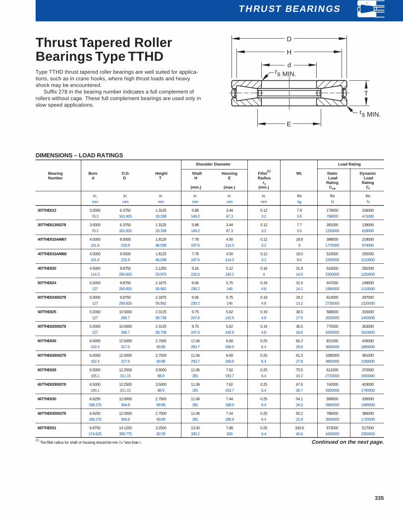
335
Thrust Tapered RollerBearings Type TTHDType TTHD thrust tapered roller bearings are well suited for applica-tions, such as in crane hooks, where high thrust loads and heavyshock may be encountered.
Suffix 278 in the bearing number indicates a full complement ofrollers without cage. These full complement bearings are used only inslow speed applications.
DIMENSIONS – LOAD RATINGSShoulder Diameter Load Rating
Bearing Bore O.D. Height Shaft Housing Fillet(1)
Wt. Static DynamicNumber d D T H E Radius Load Load
rs Rating Rating(min.) (max.) (min.) C oa Ct
in. in. in. in. in. in. lbs lbs lbsmm mm mm mm mm mm kg N N
30TTHD013 3.0000 6.3750 1.3125 5.88 3.44 0.12 7.9 179000 10600076.2 161.925 33.338 149.2 87.3 3.2 3.6 796000 471000
30TTHD01300278 3.0000 6.3750 1.3125 5.88 3.44 0.12 7.7 281000 13900076.2 161.925 33.338 149.2 87.3 3.2 3.5 1250000 618000
40TTHD015AA967 4.0000 8.5000 1.8125 7.78 4.50 0.12 19.8 398000 219000101.6 215.9 46.038 197.6 114.3 3.2 9 1770000 974000
40TTHD015AA968 4.0000 8.5000 1.8125 7.78 4.50 0.12 19.0 515000 250000101.6 215.9 46.038 197.6 114.3 3.2 8.6 2290000 1110000
45TTHD020 4.5000 9.8750 2.1250 9.16 5.12 0.16 31.9 516000 281000114.3 250.825 53.975 232.6 130.2 4 14.5 2300000 1250000
50TTHD024 5.0000 9.8750 2.1875 9.06 5.75 0.19 31.0 447000 249000127 250.825 55.562 230.2 146 4.8 14.1 1990000 1110000
50TTHD02400278 5.0000 9.8750 2.1875 9.06 5.75 0.19 29.2 614000 297000127 250.825 55.562 230.2 146 4.8 13.2 2730000 1320000
50TTHD025 5.0000 10.5000 2.3125 9.75 5.62 0.19 38.5 588000 315000127 266.7 58.738 247.6 142.9 4.8 17.5 2620000 1400000
50TTHD02500278 5.0000 10.5000 2.3125 9.75 5.62 0.19 36.5 770000 363000127 266.7 58.738 247.6 142.9 4.8 16.6 3420000 1610000
60TTHD026 6.0000 12.5000 2.7500 11.56 6.69 0.25 65.2 821000 426000152.4 317.5 69.85 293.7 169.9 6.4 29.6 3650000 1890000
60TTHD02600278 6.0000 12.5000 2.7500 11.56 6.69 0.25 61.3 1080000 491000152.4 317.5 69.85 293.7 169.9 6.4 27.8 4800000 2180000
65TTHD029 6.5000 12.2500 3.5000 11.06 7.62 0.25 75.5 611000 370000165.1 311.15 88.9 281 193.7 6.4 34.2 2720000 1650000
65TTHD02900278 6.5000 12.2500 3.5000 11.06 7.62 0.25 67.6 742000 403000165.1 311.15 88.9 281 193.7 6.4 30.7 3300000 1790000
66TTHD030 6.6250 12.0000 2.7500 11.06 7.44 0.25 54.1 599000 335000168.275 304.8 69.85 281 188.9 6.4 24.5 2660000 1490000
66TTHD03000278 6.6250 12.0000 2.7500 11.06 7.44 0.25 50.2 786000 386000168.275 304.8 69.85 281 188.9 6.4 22.8 3500000 1720000
68TTHD031 6.8750 14.1250 3.2500 13.00 7.88 0.25 100.6 973000 517000174.625 358.775 82.55 330.2 200 6.4 45.6 4330000 2300000
(1) The fillet radius for shaft or housing should be min 1⁄64" less than r. Continued on the next page.
E
rs MIN.
D
T
H
d
rs MIN.
THRUST BEARINGS

336
THRUST BEARINGS
Thrust TaperedRoller BearingsType TTHD(continued)
DIMENSIONS –LOAD RATINGSShoulder Diameter Load Rating
Bearing Bore O.D. Height Shaft Housing Fillet(1)
Wt. Static DynamicNumber d D T H E Radius Load Load
rs Rating Rating(min.) (max.) (min.) C oa Ct
in. in. in. in. in. in. lbs lbs lbsmm mm mm mm mm mm kg N N
70TTHD032 7.0000 14.5000 3.2500 13.25 8.00 0.31 104.2 1040000 538000177.8 368.3 82.55 336.6 203.2 7.9 47.3 4640000 2390000
70TTHD03200278 7.0000 14.5000 3.2500 13.25 8.00 0.31 96.4 1370000 620000177.8 368.3 82.55 336.6 203.2 7.9 43.7 6100000 2760000
70TTHD033 7.0000 17.0000 4.0000 15.69 8.06 0.31 191.0 1800000 882000177.8 431.8 101.6 398.4 204.8 7.9 86.6 7980000 3920000
80TTHD034 8.0000 16.5000 3.6250 15.12 8.88 0.38 150.4 1400000 705000203.2 419.1 92.075 384.2 225.4 9.5 68.2 6210000 3140000
80TTHD03400278 8.0000 16.5000 3.6250 15.12 8.88 0.38 139.5 1830000 813000203.2 419.1 92.075 384.2 225.4 9.5 63.3 8150000 3620000
81TTHD035 8.1250 16.5000 4.7500 14.81 9.19 0.38 198.0 1380000 770000206.375 419.1 120.65 376.2 233.4 9.5 89.8 6150000 3420000
90TTHD039 9.0000 19.0000 4.1250 17.56 10.19 0.44 230.1 2060000 1010000228.6 482.6 104.775 446.1 258.8 11.1 104.4 9160000 4510000
90TTHD03900278 9.0000 19.0000 4.1250 17.56 10.19 0.44 213.3 2540000 1120000228.6 482.6 104.775 446.1 258.8 11.1 96.7 11300000 4960000
92TTHD039 9.2500 19.0000 4.1250 17.56 10.19 0.44 223.1 2060000 1010000234.95 482.6 104.775 446.1 258.8 11.1 101.2 9160000 4510000
92TTHD043 9.2500 21.5000 5.0000 19.75 10.62 0.62 377.4 2740000 1370000234.95 546.1 127 501.6 269.9 15.9 171.2 12200000 6100000
100TTHD045 10.0000 21.2500 4.6250 19.62 11.25 0.44 326.0 2700000 1280000254 539.75 117.475 498.5 285.8 11.1 147.8 12000000 5680000
110TTHD047 11.0000 23.7500 5.3750 21.75 12.50 0.44 478.7 3190000 1600000279.4 603.25 136.525 552.4 317.5 11.1 217.1 14200000 7120000
110TTHD04700278 11.0000 23.7500 5.3750 21.75 12.50 0.44 438.6 3990000 1770000279.4 603.25 136.525 552.4 317.5 11.1 198.9 17700000 7860000
160TTHD064* 16.0000 28.0000 5.7500 26.00 17.69 0.38 608.8 3770000 1880000406.4 711.2 146.05 660.4 449.3 9.5 276.1 16800000 8370000
160TTHD065* 16.0000 33.0000 7.0000 30.56 18.06 0.50 1168.8 6240000 3100000406.4 838.2 177.8 776.3 458.8 12.7 530.1 27800000 13800000
160TTHD06500278* 16.0000 33.0000 7.0000 30.56 18.06 0.50 1068.7 7710000 3410000406.4 838.2 177.8 776.3 458.8 12.7 484.7 34300000 15200000
(1) The fillet radius for shaft or housing should be a minimum of 1⁄64" less than r.
E
rs MIN.
D
T
H
d
rs MIN.

337
Thrust TaperedRoller BearingsType TTVFThrust V-Flat Tapered Roller bearings Type TTVF combine theoutstanding features of thrust tapered and cylindrical roller bearings tooffer the highest possible capacity of any thrust bearing of its size. Inthe V-Flat design, one washer is perfectly flat, while the secondincludes a tapered raceway matching the rollers. The design wasoriginally developed for screwdown applications in metal rolling millswhere thrust loads exceeding one million pounds are common.
DIMENSIONS – LOAD RATINGSWashers Shoulder Diameter Load Rating
Approx.Bearing Bore O.D. Height Thickness Small Large Shaft Housing Fillet
(1)Wt. Static Dynamic Limiting
Number d D T T 1 Diameter Bore H E Radius Load Load SpeedO.D. I.D. rs Rating Rating (oilD1 d1 Coa Ct bath
(min.) (max.) (max) only)
in. in. in. in. in. in. in. in. in. lbs lbs lbsmm mm mm mm mm mm mm mm mm kg N N rpm
F-3167-B 3.9990 8.4990 1.8125 0.375 8.470 4.039 7.62 4.25 0.10 20.5 353000 198000 1350101.575 215.875 46.038 9.53 215.14 102.59 193.7 108 2.5 9.3 1570000 880000
W-3217-B 5.0000 10.5000 2.3125 0.500 10.470 5.020 9.38 5.88 0.14 41.0 578000 304000 1090127.000 266.700 58.738 12.70 265.94 127.51 238.1 149.2 3.6 18.6 2570000 1350000
S-4055-C 5.9045 11.8000 3.5312 1.000 11.750 6.063 10.53 6.88 0.12 79.0 754000 416000 970149.974 299.720 89.692 25.40 298.45 154 267.5 174.6 3 35.8 3350000 1850000
G-3304-B 6.6250 12.0000 2.7500 0.562 11.938 6.750 10.94 7.44 0.25 57.0 839000 429000 950168.275 304.800 69.850 14.29 303.21 171.45 277.8 188.9 6.4 25.9 3730000 1910000
W-3218-B 7.0000 14.5000 3.2500 0.688 14.438 7.125 13.25 8.00 0.24 109.0 1410000 660000 790177.800 368.300 82.550 17.46 366.71 180.98 336.6 203.2 6.1 49.4 6270000 2940000
F-3094-C 8.9990 16.9980 3.5000 0.625 16.968 9.125 15.62 10.12 0.20 158.0 1600000 769000 670228.575 431.749 88.900 15.88 430.99 231.78 396.9 257.2 5.1 71.7 7120000 3420000
I-2077-C 9.9990 20.0000 3.7500 0.750 19.968 10.094 18.44 11.12 0.25 243.0 2260000 1020000 570253.975 508.000 95.250 19.05 507.19 256.38 468.3 282.6 6.4 110.2 10000000 4530000
R-2927-C 10.0000 20.0000 4.2500 0.844 19.938 10.125 18.38 11.25 0.19 272.0 2720000 1250000 570254.000 508.000 107.950 21.43 506.41 257.18 466.7 285.8 4.8 123.4 12100000 5550000
G-3224-C 10.1000 21.5000 6.5000 1.375 21.375 10.188 20.31 11.88 0.24 501.0 3350000 1780000 530256.540 546.100 165.100 34.92 542.92 258.76 515.9 301.6 6.1 227.2 14900000 7900000
S-4077-C 10.2362 18.8956 5.2000 1.062 18.833 10.361 16.81 11.81 0.19 279.0 2020000 1060000 610259.999 479.948 132.080 26.99 478.36 263.17 427 300 4.8 126.5 8980000 4720000
C-8091-C 11.0000 23.7500 5.3750 1.188 23.688 11.125 21.75 12.50 0.19 508.0 3980000 1770000 480279.400 603.250 136.525 30.16 601.66 282.58 552.4 317.5 4.8 230.4 1770000 7890000
(1) Maximum shaft or housing fillet radius which bearing corners will clear. Continued on the next page.
H
d
E
D
T
D1
rs MAX.
rs MAX.d1
T1
THRUST BEARINGS

338
THRUST BEARINGS
Thrust TaperedRoller BearingsType TTVF (continued)
DIMENSIONS – LOAD RATINGSWashers Shoulder Diameter Load Rating
Approx.Bearing Bore O.D. Height Thickness Small Large Shaft Housing Fillet
(1)Wt. Static Dynamic Limiting
Number d D T T 1 Diameter Bore H E Radius Load Load SpeedO.D. I.D. rs Rating Rating (oilD1 d1 Coa Ct bath
(min.) (max.) (max.) only)
in. in. in. in. in. in. in. in. in. lbs lbs lbsmm mm mm mm mm mm mm mm mm kg N N rpm
G-3272-C 11.9990 24.0000 4.5000 1.125 23.890 12.094 22.25 13.50 0.25 421.0 3990000 1660000 480304.775 609.600 114.300 28.58 606.81 307.18 565.2 342.9 6.4 190.9 17800000 7380000
E-1994-C 12.0000 26.5000 6.7500 1.469 26.438 12.125 23.94 13.88 0.30 767.0 5100000 2470000 430304.800 673.100 171.450 37.31 671.51 307.98 608 352.4 7.6 347.8 22700000 11000000
F-3090-A 12.0000 29.0000 11.0000 1.750 28.938 12.125 24.19 15.19 0.36 1614.0 6300000 3850000 400304.800 736.600 279.400 44.45 735.01 307.98 614.4 385.8 9.1 732 28000000 17100000
I-2060-C 14.5095 23.9825 4.7500 1.000 23.812 14.625 22.25 15.81 0.38 388.0 2640000 1310000 480368.541 609.156 120.650 25.40 604.84 371.48 565.2 401.6 9.7 176 11800000 5840000
B-8350-C 16.0000 28.0000 6.5781 1.453 27.938 16.125 25.75 17.75 0.36 786.0 4480000 2310000 410406.400 711.200 167.084 36.91 709.61 409.58 654 450.8 9.1 356.5 19900000 10300000
F-3163-C 16.0000 28.0470 5.7500 1.219 28.003 16.125 25.62 17.94 0.30 669.0 4350000 2070000 410406.400 712.394 146.050 30.96 711.28 409.58 650.9 455.6 7.6 303.4 19300000 9190000
F-3131-G 17.0000 34.0000 9.0000 1.750 33.938 17.125 31.00 19.25 0.40 1708.0 8480000 4230000 340431.800 863.600 228.600 44.45 862.01 434.98 787.4 489 10.2 774.6 37700000 18800000
A-6096-C 20.0000 39.0000 7.7500 2.656 39.000 20.062 36.50 22.19 0.50 1946.0 9320000 3760000 290508 990.600 196.850 67.47 990.60 508.58 927.1 563.6 12.7 882.5 41500000 16700000
F-3093-A 22.0000 42.0000 11.2500 2.250 41.938 22.125 37.50 25.19 0.40 3090.0 11100000 6300000 270558.800 1066.800 285.750 57.15 1065.21 561.98 952.5 639.8 10.2 1401.4 49400000 28000000
F-3172-C 28.0000 38.0000 5.0000 1.188 37.938 28.125 36.12 30.00 0.19 781.0 4400000 1950000 300711.2 965.200 127 30.16 963.61 714.38 917.6 762 4.8 354.2 19600000 8670000
H-2054-G 28.0000 39.0000 7.5000 1.750 38.938 28.062 36.88 29.75 0.40 1262.0 6300000 3200000 290711.2 990.600 190.500 44.45 989.01 712.79 936.6 755.6 10.2 572.3 28000000 14200000
D-2864-C 32.4970 46.0000 5.0000 1.250 46.000 32.500 44.50 33.88 0.56 1212.0 9920000 3500000 250825.424 1168.400 127 31.75 1168.40 825.50 1130.3 860.4 14.2 549.7 44100000 15600000
F-3067-C 48.0314 62.0027 7.0000 1.750 62.008 48.031 59.00 49.88 0.25 2587.0 11200000 4930000 1801219.998 1574.869 177.800 44.45 1575 1219.99 1498.6 1266.8 6.4 1173.2 49900000 21900000
(1) Maximum shaft or housing fillet radius which bearing corners will clear.
H
d
E
D
T
D1
rs MAX.
rs MAX.d1
T1

339
Thrust Tapered RollerBearings Type TTVSV-Flat Tapered Roller bearings Type TTVS have the same basic rollerand raceway design as the TTVF except that the lower washer is twopieces, to permit self-alignment under conditions of initial misalignment.
DIMENSIONS – LOAD RATINGSWashers Shoulder Diameter Load Rating
Approx.Bearing Bore O.D. Height Thickness Small Large Shaft Housing Fillet
(1)Wt. Static Dynamic Limiting
Number d D T T 1 Diameter Bore H E Radius Load Load SpeedO.D. I.D. rs Rating Rating (oilD1 d1 Coa Ct bath
(min.) (max.) (max.) only)
in. in. in. in. in. in. in. in. in. lbs lbs lbsmm mm mm mm mm mm mm mm mm kg N N rpm
B-7976-C 7.2500 16.0000 8.0000 2.625 15.938 7.375 13.62 9.00 0.24 347.0 1720000 1020000 720184.15 406.4 203.2 66.68 404.81 187.32 346.1 228.6 6.1 157.4 7650000 4540000
B-8824-C 7.8730 15.7460 4.7969 1.433 15.625 8.000 14.12 9.47 0.16 190.0 1580000 807000 730199.374 399.948 121.841 36.4 396.88 203.2 358.8 240.5 4.1 86.2 7020000 3590000
E-2004-C 9.0000 18.9980 6.2500 1.768 18.880 9.125 16.50 11.12 0.19 375.0 2440000 1320000 600228.6 482.549 158.75 44.91 479.55 231.78 419.1 282.6 4.8 170.1 10900000 5870000
H-1685-C 9.5000 19.2480 6.0000 2.250 19.000 9.531 17.00 11.00 0.24 359.0 2240000 1120000 600241.3 488.899 152.4 57.15 482.6 242.09 431.8 279.4 6.1 162.8 9940000 4980000
W-3120-C 9.9990 20.0000 8.5000 2.437 19.875 11.250 16.75 12.50 0.40 553.0 2200000 1350000 580253.975 508 215.9 61.91 504.82 285.75 425.4 317.5 10.2 250.8 9770000 6020000
P-1739-C 12.0000 24.0000 8.5000 2.437 23.938 12.125 21.12 13.75 0.30 793.0 4010000 2260000 480304.8 609.6 215.9 61.91 608.01 307.98 536.6 349.2 7.6 359.6 17800000 10000000
N-2827-G 14.0000 26.0000 10.0000 3.000 25.875 14.125 22.75 16.25 0.40 1065.0 4180000 2490000 440355.6 660.4 254 76.2 657.22 358.78 577.8 412.8 10.2 483 18600000 11100000
B-8424-C 16.0000 34.2500 9.5000 3.250 34.938 17.250 31.62 18.25 0.65 1892.0 8770000 3980000 330406.4 869.95 241.3 82.55 887.41 438.15 803.3 463.6 16.5 858 39000000 17700000
(1) Maximum shaft or housing fillet radius which bearing corners will clear.
rs MAX.
H
d
D1
rs MAX.
E
D
d1
TT1
THRUST BEARINGS