superior machine vision solutions through multi-shot imaging
TRANSCRIPT

ComputationalImaging
Superior Machine Vision Solutions throughMulti-shot Imaging
Get the image you need ™
LSS Series Controllers and LightingOpen-architecture lighting systems for Computational Imaging

What is Computational Imaging?
Computational Imaging (CI) refers to digital image capture and processing techniques that combine computation and optical encoding. Relying on data extracted and computed from a series of input images captured under different lighting or optical conditions, CI can improve the capability of a camera or introduce new features not previously possible. By creating an output image focused on the image properties most important to a particular machine vision task, CI offers powerful advantages over traditional one-shot imaging.
In this summary we introduce the concept of Computational Imaging with an analogy from the consumer sector, and then explain how this technology is making an ever greater impact in high performance Machine Vision (MV) applications.
Analogy with the consumer environment Consumers want functionality such as the ability to hold up their cell phones and snap the perfect selfie with the sun setting over the beach behind them; they want to sweep them left to right in order to create panorama shots that challenge even the best of wide angle lenses!
Responding to this demand, computational imaging has slowly crept its way into the cameras on smart phones and other por-table devices as the following example illustrates.
In the case of the setting sun, the sun and sky are often thou-sands of times brighter than the subject of the selfie. The dy-namic range of the small imagers used in cell phones is easily exceeded, yet the consumer expects to clearly see both their face and the brilliantly lit sky. To meet this expectation, many of the top cell phones now snap 2 or 3 pictures in rapid succes-sion, each with a different exposure level. Invisible to the user, an algorithm in the background picks the most usable pixels in each image, weights them relative to each exposure level, and combines them into one single high dynamic range (HDR) image with a total dynamic range greater than possible with a single image capture.
These techniques and many more are part of a trend to use mul-tiple images to create a single computed output image and fit into an area called Computational Imaging.
Computational Imaging in Machine VisionAdvances in technology and the latest high speed CMOS cam-eras are making many computational imaging techniques viable for Machine Vision applications. With CI, system designers can start to think in new ways about creating solutions to difficult imaging problems.
Unlike traditional image acquisition, which often requires sub-stantial post-capture image processing and still falls short in producing the optimal image, CI – with its targeted feature extraction – directly outputs the image you need, allowing for more robust MV solutions. Better or previously impossible im-ages for Machine Vision systems can be created at a lower cost.
By using multiple image captures and processing the comput-ed composite image, or “super image”, computational imaging directly outputs the image you need - shortening development time and enabling far superior MV solutions.
Computational imaging is easier than ever to implement into al-most any vision system. With today’s MV hardware, CI technol-ogy can support even rapidly moving objects with ease. In the following pages we outline some of the typical functions that can be accomplished with applications that previously would have been difficult.
Illumination for Computational Imaging Computational Illumination is a necessary component of com-putational imaging. It refers to controlling illumination in a structured fashion, to encode the relevant information needed for digital processing. Typically, programmable lighting systems are used to create lighting sequences that vary application-spe-cific parameters such as illumination direction or angle, wave-length, intensity, or focus.
Typical Computational Imaging functions for Machine Vision
These and many more possibilities allow vision system builders to get the most beneficial image for their application.
Photometric Stereo (PMS) High Dynamic Range imaging (HDR) Ultra-Resolution Color (URC) Extended Depth of Field (EDOF) Bright Field/Dark Field Multi-spectral Imaging 360° object capture
- Generate edge and texture images using shape from shading- Create images with higher contrast ratios- Create higher resolution color images with no interpolation artifacts- Improve measurements without losing light or reducing magnification- Combine the advantages of two well-known lighting techniques- Enhance images with maximum contrast from multiple spectral bands- Panoramic imaging with singly triggered, multiple scene acquisition

Principle of operation
Currently, there are many examples of computational imaging techniques, each with its own set of processes and resulting benefits - the examples illustrated in this brochure are just a few of the many possibilities of this technology. In this section we introduce the following key principles of computational imaging:
• Computation is inherent in the image formation process• Combines special optics and/or lighting along with image processing during image capture• Typically involves a sequence of images with different illumination for each frame• Covers a wide variety of techniques, all designed to output better images or images with unique characteristics• Ends with the image acquisition process – does not involve image analysis
For machine vision, CI enables you to GET THE IMAGE YOU NEED!
Example using ultra-resolution color imagingWith the illustrated example below we show the practical elements that comprise the key steps of computational imaging. These steps can be generalized as computational illumination/optical encoding, image capture and image processing/decoding. Using a monochrome camera with a CCS full-color ring light, which has 3-channel control of red, green, and blue output, the user can generate full resolution RGB color images at practical data rates. By grabbing a sequence of 3 monochrome images correlated to red, green, and blue strobes, a full color composite image at the full monochrome resolution can be created by aligning the images and using the red, green, and blue values for each pixel to create the color pixel.
Advantages of composite imagesIn this example, the resulting composite color images are much sharper than that of a single image capture with a Bayer or mosaic color camera. The images are similar to those from 3-chip cameras without the expense, special prism or lens limitations, and at much higher resolutions than that of available 3-chip cameras. The advantage of this method is the ability to have the best of both worlds; complete color information at the full pixel resolution of the imager. Due to the spatial effects of interpolation, Bayer color imagers capture the color information, but lose spatial resolution across several pixels.

Practical application examples
Ultra-Resolution Color (URC)Here we take a look at a practical example of the concept out-lined in the previous section on the principle of Computational Imaging.
Three monochrome full resolution images are captured se-quentially. To get the color information, each image is strobed with a single color - Red, Green, or Blue. A color image with the full resolution of the monochrome camera can be created from the data of the 3 input images. In this example, 3 monochrome 8-bit 1600 x 1200 images are combined to make a 24-bit color 1600 x 1200 image.
Composite Color ImageThe advantages of this method to create composite color images be-come apparent as you zoom into feature details, as you might in a machine vision inspection.
In the zoomed image 1a, you can see the two exposed windings of the coil wire and the exit wire to the solder point. The edges are sharp and transitions are smooth with good contrast. In image 1b, the Bayer interpolation artifacts cause the wire to alias red + green along its length. Contrast to the background and between wire layers is reduced and noisy.
You can see similar effects in the 2a + 2b zoomed images. In the Bayer image 2b, the white silkscreen is almost completely Bayer noise. The red/gold/black boundaries of the test point in the lower corner become blurred and wider. In the 2a equivalent image, the silkscreen and test point are sharper, with good contrast and color.
Bright Field + Dark FieldBright field and dark field are two common methods of illumi-nation for machine vision inspection. Normally, they are used independently, as most samples image best using one method or the other. But what if your sample contains some features that can only be seen with bright field, and other features that can only be seen with dark field?
Multi-shot imaging nicely solves this problem through the use of a combined bright field/dark field illuminator. The bright field image is combined with the dark field image to generate an output image which contains the features or defects found in both input images.
1a 2a 1b 2bComposite image Bayer image
Oil drop on scratched glass plateThe piece of glass in this example contains several types of common defects – microscopic particles, fine scratches, pits, and oil droplets on the surface.
Bright field imaging shows the droplets and larger particles, but not the fine surface details. Dark field imaging highlights all the surface details, readily showing the scratches, pits and microscopic particles. While neither bright field or dark field lighting show everything, a CI process can produce an output image that does.

Tire inspection with PMSThe images in this example were captured with four long bar lights arranged in a square pattern around the tire. The quadrants were fired in sequence to create the East, South, North, West images on the left.
Tire Texture and Tire Shape images are then created by com-bining these images in software as shown. The PMS routine removes the visual noise and leaves only the features of interest. The contrast of the sidewall printing is greatly en-hanced, simplifying OCR or OCV and increasing accuracy.
The Texture image is often useful for showing surface col-oring without interference from surface structure or for re-moving glare from reflective surfaces. In this example, only the Shape image shows useful information.
Practical application examples
Photometric Stereo (PMS)Photometric stereo allows the user to separate the shape of an object from its 2D texture. Its primary purpose is to accentuate the three-dimensional surface structure of an object. It works by firing segmented light arrays from multiple angles and then pro-cessing the resulting shadow images in a process called “shape from shading”. It is useful for the detection of small surface defects and 3D surface reconstruction. PMS is a height driven process which can enhance surface details like scratches, dents, pin holes, raised printing, or engraved characters. Because the final image is a computed surface based on the shading information, surface coloring or features without height are removed. This can make visually noisy or highly reflective surfaces easier to inspect. PMS is especially effective on surfaces that have 3D structure but little to no contrast. This capability is rapidly becoming popular in the MV market.
A basic PMS system uses lighting from four or more directions to cast a directional shadow around raised or sunken features on an object. The illumination may be a ring light with four 90 degree quadrants, an array of four bar lights, or any other arrangement that produces directional lighting. The feature map can be applied through different algorithms to show surface details that are hard to find or can’t be detected in pure visual or machine vision images.
Tire - E
Tire Texture Tire Shape
Tire - S Tire - N Tire - W

Practical application examples
High Dynamic Range (HDR)All imagers have a limit to the ratio of the brightest object to the darkest object that can be distinguished in a single image. This is called the dynamic range. Many machine vision applica-tions involve bright, shiny, or dark objects that challenge the dynamic range of the camera. To solve these cases, a series of images with different exposure levels can be captured to create a single HDR image with all the detail that needs to be included for the inspection.
HDR imagingThis HDR image is created from 3 images with different ex-posures. Image 1 lets you see the LED die and surrounding package, but no other details are visible. Image 2 exposure allows the silkscreen and brightest parts of the components to be seen, but the LED is oversaturated.
Image 3 allows the barrel connector and other dark com-ponents to be seen, but the text and component leads are oversaturated; the LEDs are completely washed out. The HDR image allows correct exposure of the bright LEDs, proper saturation of the silkscreen and component leads, yet the dark components can still be seen.
How to get a lot more Depth of FieldTo extend DOF, several input images cap-tured at different focal planes are neces-sary. While there are a number of methods for EDOF imaging, two common ones are:• Using motorized or liquid lenses to
vary the focal point• Using a chromatically uncorrected lens
along with multiple wavelengths of light to induce focal plane shifts
The example to the left merged three sepa-rately focused images to produce an EDOF image with all three fasteners in sharp fo-cus.
Extended Depth of Field (EDOF)All images have a depth of field (DOF), a distance over which objects appear in sharp focus. In any single image, DOF is limited by the magnification and aperture size used. In some machine vision applications, the DOF may not be great enough to focus sharply on all the objects in a scene. Conventional solutions for increasing DOF such as closing the aperture (higher f/#) come with sub-stantial tradeoffs such as decreased light and less resolution.
The EDOF technique allows an image to be created with a DOF greater than any of the single images. Using EDOF image processing software and the CCS computational illumination kit, multiple images with various depths of field can be merged to return a clear, sharp result - without loss of light or resolution.
+ +
=HDR IMAGE
Dark Exposure Medium Exposure Bright Exposure
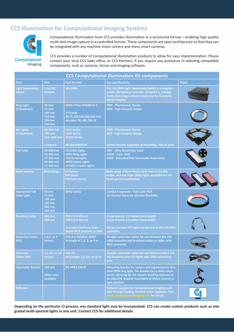
CCS Illumination for Computational Imaging SystemsComputational Illumination from CCS provides illumination in a structured format – enabling high quality multi-shot image capture in a controlled fashion. These components are open-architecture so that they can be integrated with any machine vision camera and many smart cameras.
CCS provides a number of Computational Illumination products to allow for easy implementation. Please contact your local CCS Sales office, or CCS Partners, if you require any assistance in selecting compatible components, such as cameras, lenses and imaging software.
CCS Computational Illumination Kit componentsItem Size Part Number Key specifications Photo
Light Sequencing Switch
1.5x DINModule
LSS-2404 The LSS-2404 Light Sequencing Switch is a program-mable LED lighting controller designed to manage multi-shot image capture sequences for Computa-tional Imaging.
Ring Light(4 Quadrant)
50 mm75 mm100 mm150 mm200 mm250 mm
HPR2-YYYxx-DV04M12-5
YYY=size: 50,75,100,150,200,250 mmxx=color: BL, RD, SW, IR
PMS - Photometric Stereo HDR - High Dynamic Range
Bar Lights(4 Quadrant)
33-509 mm300 mm150-1500 mm
Universal
LDL2 SeriesLDLB Series HLDL2 Series
BK-QUADBAR-4C
PMS - Photometric Stereo HDR - High Dynamic Range
Corner Bracket Assembly w/mounting - Fits all sizes
Full Color 33-509 mm50-400 mm27-500 mm50-400 mm13-200 mm
LDL2 Bar LightsHPR2 Ring LightsTH2 Panel LightsHPD2 Dome LightsLFV3(A) Coaxial Lights
URC - Ultra-Resolution ColorCHDR - Color HDREDOF - Extended DOF (chromatic dispersion)
Multi-spectral Wide Range UV SeriesNIR SeriesFull Color Series
Wide range of form factors and sizes in UV, NIR, visible, and Full Color (RGB) lights available for any multi-spectral application.
Segmented Full Color Light
50 mm75 mm100 mm150 mm200 mm250 mm
HPR2 Series Combo 4-segment + Full Color RGB12-channel input for ultimate flexibility
Breakout Cable 300 mm900 mm
FCB-F-0.3-XS2-zzz FCB-F-0.9-XS2-zzz
zzz=Light Connector type: Blank=M12 (default) or SM3
4-way branch, 0.3 meters total length 4-way branch, 0.9 meters total length
Allows any four CCS lights to connect to the LSS-2404 controller.
Extension Cables M12
1,3,5, or 9meters
FCB-X-0.5SQM12-5M5FX=length of 1,3, 5, or 9 m
Straight extension cables for use between the LSS- 2404 controller and breakout cables or lights with M12 connector.
ExtensionCables SM3
1,2,3,5, or 10meters
FCB-XXXX=Length: 1,2,3,5, or 10 m
Straight extension cables for use between FCB-F-X.X- XS2 branches and CCS lights with SM3 connectors only.
Adjustable Bracket 150 mm
Other sizes available
BK-HPR2-150-IS Mounting bracket for camera and segmented or stan-dard HPR2 ring light. The bracket has a slider mech-anism, allowing for the camera working distance to be adjusted. Bracket mountable at either camera or light position.
Software Software support for Computational Imaging avail-able through leading machine vision suppliers. Visit www.computationalimaging.com for details.
Depending on the particular CI process, any standard light may be incorporated. CCS can create custom products such as inte-grated multi-spectral lights in one unit. Contact CCS for additional details.
ComputationalImaging

LSS-2404 SpecificationsDescription The LSS-2404 Light Sequencing Switch is designed to be the heart of any CI system and can switch external +24 VDC
power for up to 4-channels of lights. Upon receiving an external system trigger, the LSS-2404 executes a pre-pro-grammed sequence of lighting on the 4-channels and outputs a correlated camera trigger, automatically timing an external camera exposure to the programmed lighting sequence. May be set-up as master or slave in a system.
Number of lighting channels 4
Input voltage 10.8 – 28.8 VDC (absolute range); suitable for either 12 V or 24 V DC lighting.
Power consumption 5W maximum internal dissipation; excluding attached lighting and dependent on configuration.
Trigger Out (to camera) Selectable to 5 V, 12 V, or 24 V via software. Voltage level tolerance +/- 15%. Maximum limited to ~93% Vin
Trigger Input Voltage mode: Accepts 3.3 – 24 VDC logic level voltage with adjustable trigger levelSwitched Ground Mode: Use opto-isolators or closed contacts via direct connection without external components.
Trigger Threshold Software programmable 1 - 24 VDC trigger level in 100 mV increments Default = 9.6 V threshold to work with 12 V or 24 V trigger logic
Maximum Current Rating 1 A/ch x 4-channels; 4 A maximum all channels.
Communication Port RJ45 connector. 100BaseT Ethernet. TCP/IP protocol. Control via web-based GUI or TCP/IP command set.
Firmware User upgradeable via GUI (included).
Sequence Timing User programmable via GUI (included).
Timing Resolution Maximum Trigger rate: 10,000 fps (100 µS) Minimum output signal width: 100 µS Timing resolution: 1 µSChannel skew + jitter: <= 10 µS
Operating Temperature Range Range 0 to 40 °C
Storage Temperature Range Range -10 to 50 °C
Cooling Free air cooling (standard model)
Dimensions 4.13 x 6.15 x 1.57 inches L x W
Weight 442g
LSS Light Controller specification
For Sales and Technical Support, please contact:
www.computationalimaging.com
CCS America, Inc.6 Lincoln Knoll Lane Suite 102, BurlingtonMA 01803, USAt: +1-781-272-6900 w: www.ccsamerica.come: [email protected]
Copyright © 2018 CCS Inc. All Rights Reserved.
CCS Europe N.V.Bergensesteenweg 421B 1600 Sint-Pieters-LeeuwBelgiumt: +32-2-333-0080w: www.ccs-grp.come: [email protected]
CCS Asia PTE. LTD.35 Marsiling Industrial Estate Road 3, #05-03Singapore 739257t: +65-6363-1180w: www.ccs-asia.com.sge: [email protected]
CCS Headquarters374 Okakuencho, Shimodachiuri-agura, Karasuma-doriKamigyo-ku, Kyoto, 602-8011, Japan t: +81-75-415-8277 w: www.ccs-grp.com