superconducting magnets section iii · section i particle accelerators and magnets...
TRANSCRIPT

2019 Joint Universities Accelerator School
Superconducting MagnetsSection III
Paolo Ferracin([email protected])
European Organization for Nuclear Research (CERN)

Outine
Section IParticle accelerators and magnets
Superconductivity and practical superconductors
Section IIMagnetic design
Section IIICoil fabrication
Forces, stress, pre-stress
Support structures
Section IVQuench, training, protection
Superconducting Magnets, 18-20 February, 2019 Paolo Ferracin 2

References
Coil fabrication
Forces, stress, pre-stress
Support structures
K.-H. Mess, P. Schmuser, S. Wolff, “Superconducting accelerator magnets”, Singapore: World Scientific, 1996.
Martin N. Wilson, "Superconducting Magnets", 1983.
Fred M. Asner, "High Field Superconducting Magnets", 1999.
P. Ferracin, E. Todesco, S. Prestemon, “Superconducting accelerator magnets”, US Particle Accelerator School, www.uspas.fnal.gov.
Units 10,13,14
“LHC design report v.1: the main LHC ring”, CERN-2004-003-v-1, 2004.
Superconducting Magnets, 18-20 February, 2019 Paolo Ferracin 3

Coil fabricationWinding and curing
Superconducting Magnets, 18-20 February, 2019 Paolo Ferracin
The coil: most critical component of a superconducting magnet
Cross-sectional accuracy of few hundredths of millimeters (few mils) over up to 15 m length
Laminated tooling
4

Coil fabricationWinding and curing
Superconducting Magnets, 18-20 February, 2019 Paolo Ferracin
The cable is wound around a polemounted on a steel mandrel.
The mandrel is made of laminations
Winding starts from the pole turn of the inner layer after preparing the coil ramp for the outer layer.
Cable maintained in tension (200 N)
5
Coil fabricationWinding and curing
Superconducting Magnets, 18-20 February, 2019 Paolo Ferracin
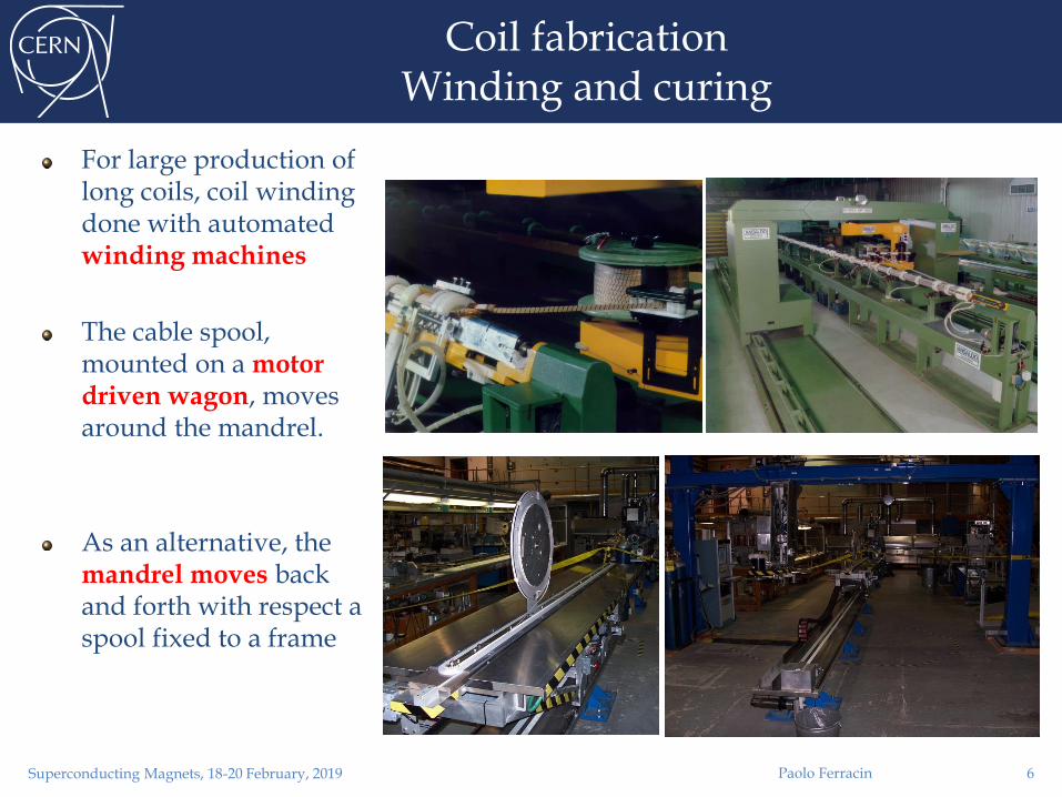
For large production of long coils, coil winding done with automated winding machines
The cable spool, mounted on a motor driven wagon, moves around the mandrel.
As an alternative, the mandrel moves back and forth with respect a spool fixed to a frame
6

Coil fabricationWinding and curing
In the end region, more difficult to constrain the turns
bent over the narrow edge
To improve the mechanical stability and to reduce the peak field end spacers
constant perimeter approach The two narrow edges of the turn in the ends follow curves of equal lengths.
In Nb-Ti magnets, end spacers are produced by 5-axis machining of epoxy impregnated fiberglass
Remaining voids are then filled by resins
In Nb3Sn magnets, end spacers are made of aluminum bronze or stainless steel.
Superconducting Magnets, 18-20 February, 2019 Paolo Ferracin 7

Coil fabricationWinding and curing
There is a minimum bending radius, which depends on the cable dimensions.
Is there a general rule?
No, but usually the bending radius is 10-15 times the cable thickness.
The cable must be constantly monitored during winding.
If the bending radius is too smallDe-cabling during winding;
Strands “pop-out”.
Superconducting Magnets, 18-20 February, 2019 Paolo Ferracin 8

Coil fabricationWinding and curing
The goal of curingGlue the turns together
Facilitate coil handling and define coil dimensions
While still on the mandrels, coils are placed in the curing mould equipped with a heating system, and compressed in curing press
Nb-Ti coils cured up to 190±3 °C at 80-90 MPa (LHC) to activate resin
In Nb3Sn coils, cable insulation is injected with ceramic binder
Cured at 150° C and at ~10-30 MPa
Superconducting Magnets, 18-20 February, 2019 Paolo Ferracin 9

Coil fabricationReaction of Nb3Sn coils
Heat treatmentCuSn and Nb are heated to 650-700 C in vacuum or inert gas (argon) atmosphere Sn diffuses in Nb and reacts to form Nb3Sn.
The cable becomes brittleThe reaction is characterized by three temperature steps
homogeneity is of about 3 °C
Superconducting Magnets, 18-20 February, 2019 Paolo Ferracin
Coils clamped in a reaction fixture made of stainless steel moldblocks.
“Minimum” pressure to avoid damaging the turns
10
Coil fabricationReaction of Nb3Sn coils
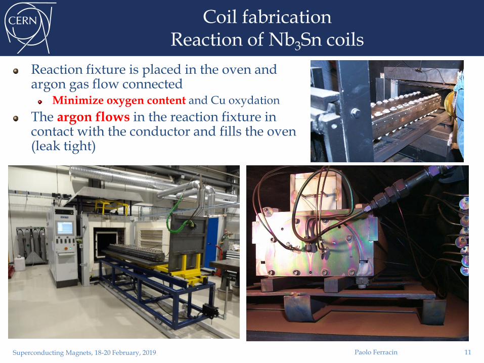
Reaction fixture is placed in the oven and argon gas flow connected
Minimize oxygen content and Cu oxydation
The argon flows in the reaction fixture in contact with the conductor and fills the oven (leak tight)
Superconducting Magnets, 18-20 February, 2019 Paolo Ferracin 11

Coil fabricationVacuum impregnation of Nb3Sn coils
After reaction, coil placed in a impregnation fixture
The fixture is inserted in a vacuum tank, evacuated epoxy injected
Epoxy has high viscosity at room temperature
low viscosity at ~60 °C
Then, curing at ~150 °C solid block
Superconducting Magnets, 18-20 February, 2019 Paolo Ferracin 12

Overview of Nb3Sn coil fabrication stages
Cured with matrix Reacted Epoxy impregnated
Paolo Ferracin
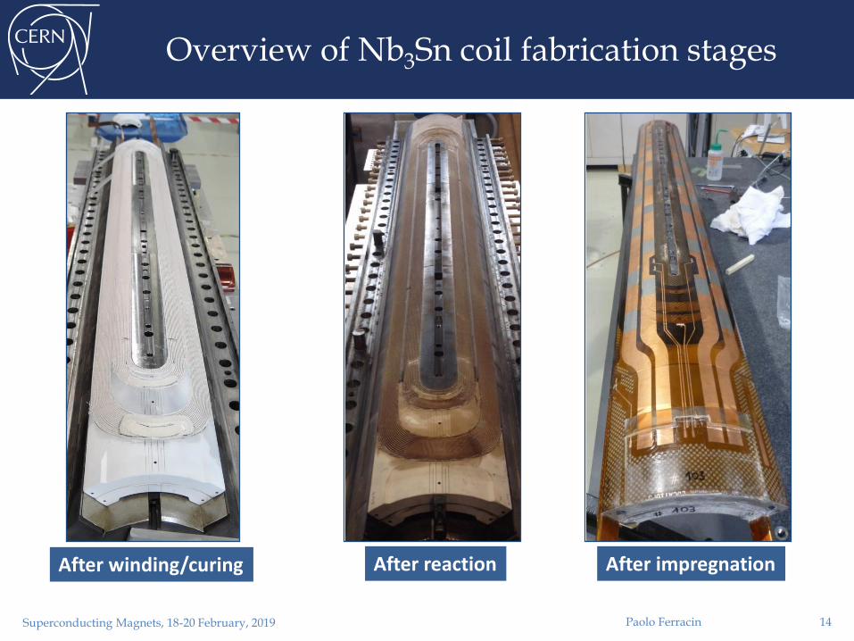
After winding/curing After reaction After impregnation
Superconducting Magnets, 18-20 February, 2019 13
Overview of Nb3Sn coil fabrication stages
Superconducting Magnets, 18-20 February, 2019 Paolo Ferracin
After winding/curing After reaction After impregnation
14

Coil fabricationQuench heaters and voltage taps
Superconducting Magnets, 18-20 February, 2019 Paolo Ferracin 15
Coil fabricationNb-Ti – Nb-Ti splices
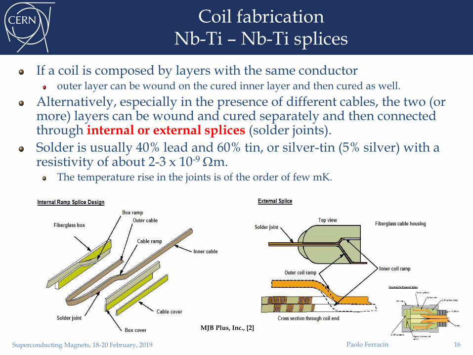
If a coil is composed by layers with the same conductorouter layer can be wound on the cured inner layer and then cured as well.
Alternatively, especially in the presence of different cables, the two (or more) layers can be wound and cured separately and then connected through internal or external splices (solder joints).
Solder is usually 40% lead and 60% tin, or silver-tin (5% silver) with a resistivity of about 2-3 x 10⁻⁹ m.
The temperature rise in the joints is of the order of few mK.
MJB Plus, Inc., [2]
Superconducting Magnets, 18-20 February, 2019 Paolo Ferracin 16

Coil fabricationNb3Sn – Nb-Ti splices
Nb-Ti leads are compressed against Nb3Sn cables for a length of about 1-1.5 time the pitch length and soldered.
Superconducting Magnets, 18-20 February, 2019 Paolo Ferracin 17

Coil fabricationFinal assembly
Additional layers of insulations, usually composed by polyimide films, are added around the coils. Besides the electrical function of guaranteeing coil-to-coil and coil-to-ground insulation, they also provide slip surfaces during assembly of the surrounding support structure (collars).
Quench protection heaters are also added to warm the entire coil after a quench.
In the HERA dipoles, 6 layers of kapton 125 mm thick.
In the RHIC dipole, glass-phenolic form
In the SSC, kapton
In the LHC dipoles, coil protection sheets made of stainless steel are used.
Superconducting Magnets, 18-20 February, 2019 Paolo Ferracin 18

Practical examplesLHC dipole coil (NbTi) fabrication steps
Winding
Curing
Coil at 190 °C under a pressure of 35 MPa
Surfacing of the heads
Voids in the ends are filled with resin
Measurements of coil azimuthal size
Superposition of the outer layer onto the inner
Splicing
Shimming of the end region
Assembly of four poles around the bore tube
Instrumentation (quench heaters) and insulation)
Paolo FerracinSuperconducting Magnets, 18-20 February, 2019 19

Superconducting Magnets, 18-20 February, 2019
Practical examplesMQXF quadrupole coil (Nb3Sn) fabrication steps
Winding of inner layer
Curing of inner layer
Coil at 150 °C under pressure (about 5 MPa)
Winding of outer layer
Curing of inner and outer layer
Coil at 150 °C under pressure (about 5 MPa)
Reaction
Second instrumentation phase
Voltage taps, quench heaters
Splicing
Impregnation
Second instrumentation phase
Soldering of wires, strain gauges
Paolo Ferracin 20

Outine
Section IParticle accelerators and magnets
Superconductivity and practical superconductors
Section IIMagnetic design
Section IIICoil fabrication
Forces, stress, pre-stress
Support structures
Section IVQuench, training, protection
Superconducting Magnets, 18-20 February, 2019 Paolo Ferracin 21

Introduction
Superconducting accelerator magnets are characterized by high fields and high current densities.
As a results, the coil is subjected to strong electro-magnetic forces, which tend to move the conductor and deform the winding.
A good knowledge of the magnitude and direction of the electro-magnetic forces, as well as of the stress of the coil, is mandatory for the mechanical design of a superconducting magnet.
Superconducting Magnets, 18-20 February, 2019 Paolo Ferracin 22

In the presence of a magnetic field B, an electric charged particle q in motion with a velocity v is acted on by a force FLcalled electro-magnetic (Lorentz) force [N]:
A conductor element carrying current density J (A/mm2) is subjected to a force density fL [N/m3]
Superconducing coil in its own field
Mechanics of superconducting magnetsElectro-magnetic force
Superconducting Magnets, 18-20 February, 2019 Paolo Ferracin 23

Magnetic pressure and forces
B acts on the coil as a pressurized gas on its container.
Infinitely long “thin-walled” solenoid, with thickness d, radius a, and current density Jθ .
The field outside the solenoid is zero. The field inside the solenoid B0
We can define a magnetic pressure pm acting on the winding
So, with a 10 T magnet, the windings undergo a pressure pm = (102)/(2· 4 10-7) = 4 107 Pa = 390 atm.
The force pressure increase with the square of the field.
A pressure [N/m2] is equivalent to an energy density [J/m3].Superconducting Magnets, 18-20 February, 2019 Paolo Ferracin
0
2
0
2
Bpm
24

Mechanics of superconducting magnetsElectro-magnetic force
The e.m. forces in a dipole/quadrupole magnet tend to push the coil Towards the mid plane in the vertical-azimuthal direction (Fy , F < 0)
Outwards in the radial-horizontal direction (Fx , Fr > 0)
Superconducting Magnets, 18-20 February, 2019 Paolo Ferracin 25

Mechanics of superconducting magnetsElectro-magnetic force
In the coil ends the e.m. forces tend to push the coilOutwards in the longitudinal direction (Fz > 0)
Superconducting Magnets, 18-20 February, 2019 Paolo Ferracin 26

Mechanics of superconducting magnetsElectro-magnetic force
The e.m. force on a dipole coil varies with the square of the bore field
linearly with the bore radius
The axial force on a dipole coil varies with the square of the bore field
with the square of the bore radius
Superconducting Magnets, 18-20 February, 2019 Paolo Ferracin
aB
Fy
x3
4
2 0
2
a
BF
y
y3
4
2 0
2
2
0
2
22
aB
Fy
z
27

Mechanics of superconducting magnetsElectro-magnetic force
Nb-Ti LHC MB values per aperture
Fx = 340 t per meter~300 compact cars
Precision of coil positioning: 20-50 μm
Fz = 27 t~weight of the cold mass
Nb3Sn dipole (HD2)Fx = 500 t per meter
Fz = 85 t
These forces are applied to an objet with a cross-section of 150x100 mm !!!
and by the way, it is brittle
Superconducting Magnets, 18-20 February, 2019 Paolo Ferracin 28

Stress and strainDefinitions
A stress or [Pa] is an internal distribution of force [N] per unit area [m2].
When the forces are perpendicular to the plane the stress is called normal stress () ; when the forces are parallel to the plane the stress is called shear stress ().
Stresses can be seen as way of a body to resist the action (compression, tension, sliding) of an external force.
A strain (l/l0) is a forced change dimension l of a body whose initial dimension is l0.
A stretch or a shortening are respectively a tensile or compressive strain; an angular distortion is a shear strain.
Superconducting Magnets, 18-20 February, 2019 Paolo Ferracin 29

Mechanics of superconducting magnetsDeformation and stress
Effect of e.m forces
change in coil shape effect on field quality
a displacement of the conductor potential release of frictional energy
Nb-Ti magnets: possible damage of kapton insulation at~150-200 MPa.
Nb3Sn magnets: possible conductor degradation at about 150-200 MPa.
All the components must be below stress limits.
Superconducting Magnets, 18-20 February, 2019 Paolo Ferracin
Displacement scaling = 50
LHC dipole at 0 T LHC dipole at 9 T
30

No pre-stress, no e.m. force
Superconducting Magnets, 18-20 February, 2019 Paolo Ferracin
Displacement scaling = 50
31
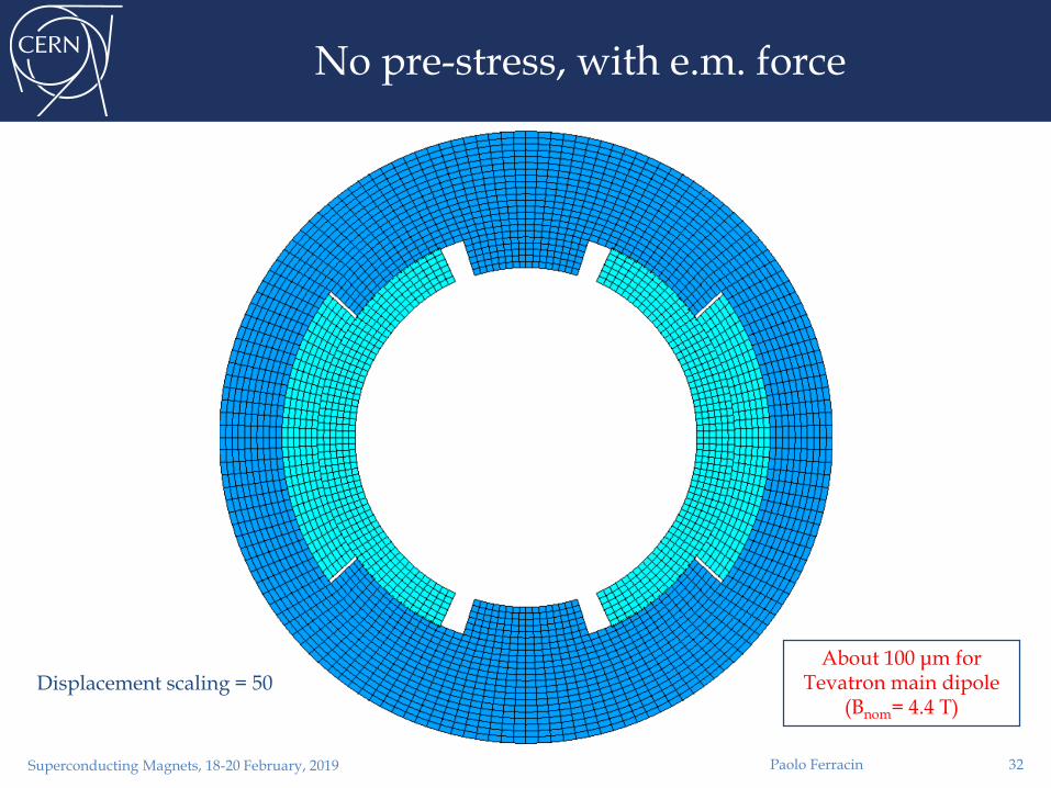
No pre-stress, with e.m. force
Superconducting Magnets, 18-20 February, 2019 Paolo Ferracin
Displacement scaling = 50About 100 μm for
Tevatron main dipole (Bnom= 4.4 T)
32

Pre-stress, no e.m. force
Superconducting Magnets, 18-20 February, 2019 Paolo Ferracin
Pole shim
Displacement scaling = 50
33

Pre-stress, with e.m. force
Superconducting Magnets, 18-20 February, 2019 Paolo Ferracin
Pole shim
Displacement scaling = 50Coil pre-stress applied
to all the accelerator dipole magnets
34

Pre-stress Tevatron main dipole
We can plot the displacement and the stress along a path moving from the mid-plane to the pole.
In the case of no pre-stress, the displacement of the pole during excitation is about -100 m.
Superconducting Magnets, 18-20 February, 2019 Paolo Ferracin 35

Pre-stress Tevatron main dipole
We now apply to the coil a pre-stress of about -33 MPa, so that no separation occurs at the pole region.
The displacement at the pole during excitation is now negligible, and, within the coil, the conductors move at most of -20 m.
Superconducting Magnets, 18-20 February, 2019 Paolo Ferracin 36

Pre-stress Tevatron main dipole
We focus now on the stress and displacement of the pole turn (high field region) in different pre-stress conditions.
The total displacement of the pole turn is proportional to the pre-stress.
A full pre-stress condition minimizes the displacements.
Superconducting Magnets, 18-20 February, 2019 Paolo Ferracin 37
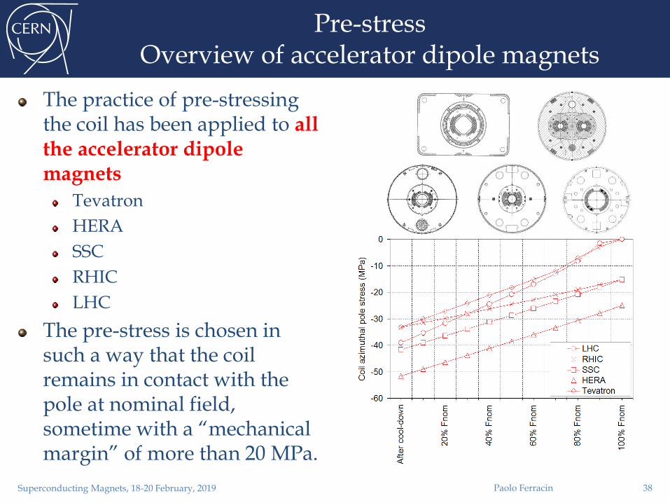
Pre-stressOverview of accelerator dipole magnets
The practice of pre-stressing the coil has been applied to all the accelerator dipole magnets
Tevatron
HERA
SSC
RHIC
LHC
The pre-stress is chosen in such a way that the coil remains in contact with the pole at nominal field, sometime with a “mechanical margin” of more than 20 MPa.
Superconducting Magnets, 18-20 February, 2019 Paolo Ferracin 38

Pre-stressGeneral considerations
As we pointed out, the pre-stress reduces the coil motion during excitation.
What about the effect of pre-stress on quench performance?
In principle less motion means less frictional energy dissipation or resin fracture.
Nevertheless the impact of pre-stress on quench initiation remains controversial
Superconducting Magnets, 18-20 February, 2019 Paolo Ferracin 39

Outine
Section IParticle accelerators and magnets
Superconductivity and practical superconductors
Section IIMagnetic design
Section IIICoil fabrication
Forces, stress, pre-stress
Support structures
Section IVQuench, training, protection
Superconducting Magnets, 18-20 February, 2019 Paolo Ferracin 40

Mechanics of superconducting magnetsSupport structures
The coil is placed inside a support structure capable ofproviding the required pre-stress to the coil after cool-down in order to reduce conductor motion;
withstanding the electro-magnetic forces;
providing Helium containment.
Superconducting Magnets, 18-20 February, 2019 Paolo Ferracin
Not in scale
Tevatron HERA SSC RHIC LHC
41
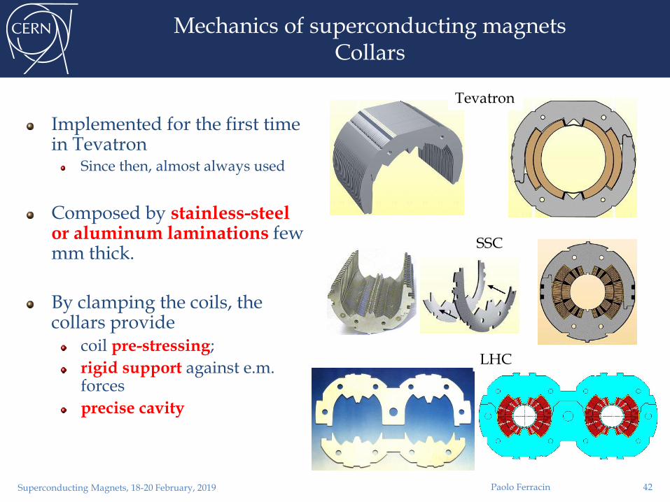
Mechanics of superconducting magnetsCollars
Implemented for the first time in Tevatron
Since then, almost always used
Composed by stainless-steel or aluminum laminations few mm thick.
By clamping the coils, the collars provide
coil pre-stressing;
rigid support against e.m. forces
precise cavity
Tevatron
SSC
LHC
Paolo FerracinSuperconducting Magnets, 18-20 February, 2019 42

Mechanics of superconducting magnetsCollars
Collaring of a dipole magnet Collaring of a quadrupole magnet
Paolo FerracinSuperconducting Magnets, 18-20 February, 2019 43

Mechanics of superconducting magnetsIron yoke
As the collars, iron yoke are made in laminations (several mm thick).
Magnetic functioncontains and enhances the magnetic field.
Structural functiontight contact with the collar
it contributes to increase the rigidity of the coil support structure and limit radial displacement.
Holes are included in the yoke design forCorrection of saturation effect
Cooling channel
Assembly features
Electrical bus
Paolo FerracinSuperconducting Magnets, 18-20 February, 2019 44

Mechanics of superconducting magnetsShell
The cold mass is contained within a shell
The shell constitutes a containment structure for the liquid Helium.
It is composed by two half shells of stainless steel welded around the yoke with high tension (about 150 MPa for the LHC dipole).
With the iron yoke, it contributes to create a rigid boundary to the collared coil.
If necessary, during the welding process, the welding press can impose the desired curvature on the cold mass
In the LHC dipole the nominal sagitta is of 9.14 mm.
W W
V2
V1
V2
V1
97.26
R 281236
LINE V1
R 281236
97.26
R 281236
LINE V2V2
2
V1
1
14343 LINE V1
14343 LINE V2
9.14
2
Paolo FerracinSuperconducting Magnets, 18-20 February, 2019 45

Mechanics of superconducting magnetsShell
Paolo FerracinSuperconducting Magnets, 18-20 February, 2019 46

Mechanics of superconducting magnetsCool-down and excitation
During cool-downComponents shrink differently
Again, coil positioning within 20-50 μm
Significant variations of coil stress
During excitationThe pole region of the coil unloads
Depending on the pre-stress, at nominal field the coil may unload completely
Superconducting Magnets, 18-20 February, 2019 Paolo Ferracin 47

Mechanics of superconducting magnetsOverview of coil stress
Collaring
Yoking and shell welding
Cool-down
Excitation
All these contributions taken into account in the mechanical design
Minimize coil motion (pre-stress)
Minimize cost and dimension of the structure
Maintain the maximum stress of the component below the plasticity limits
…and for (especially) Nb3Sn coils, limit coil stress (150-200 MPa).
Superconducting Magnets, 18-20 February, 2019 Paolo Ferracin 48

Practical examples of accelerator magnets Tevatron main dipole
The stainless steel collars are weldedin three locations per side at the end of the collaring procedure.
The stress provided by the collaring press is retained (minimum spring-back)
Warm iron design
The cold mass is composed by the collared coil; the iron is maintained at room temperature.
The compact cryostat contains a liquid helium shield and a liquid nitrogen shield.
The cold mass and cryostat are supported by four cartridges, which also contribute to the alignment of the magnet.
Paolo FerracinSuperconducting Magnets, 18-20 February, 2019 49

Practical examples of accelerator magnetsHERA main dipole
Collars are made of aluminumand are self supporting
No contact between collars and yoke.
Collared coil is locked by keys.
The iron yoke is cooled to liquid He temperature
Cold iron design.
Alignment is achieved through keys between the collars and the yoke.
The He containment is provided by two half shells welded together.
The welding process provides also the sagitta (17 mm over 9 m length).
Paolo FerracinSuperconducting Magnets, 18-20 February, 2019 50

Practical examples of accelerator magnetsSSC main dipole
Stainless steel collars are assembled into packs from spot welded pairs.
The collared-coil assembly is contained by the iron yoke and the welded a stainless steel outer shell.
Interference is provided between collars and yoke (line-to-line fit).
Two different designs
In the BNL design, the yoke is split horizontally
Tight contact results from a collar-yoke interference along the vertical diameter.
In the FNAL design, the yoke is split vertically
Tight contact results from a collar-yoke interference along the horizontal diameter.
Paolo FerracinSuperconducting Magnets, 18-20 February, 2019 51
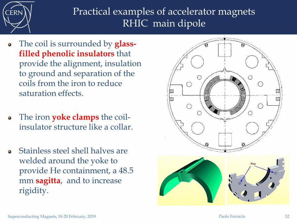
Practical examples of accelerator magnetsRHIC main dipole
The coil is surrounded by glass-filled phenolic insulators that provide the alignment, insulation to ground and separation of the coils from the iron to reduce saturation effects.
The iron yoke clamps the coil-insulator structure like a collar.
Stainless steel shell halves are welded around the yoke to provide He containment, a 48.5 mm sagitta, and to increase rigidity.
Paolo FerracinSuperconducting Magnets, 18-20 February, 2019 52

Practical examples of accelerator magnetsLHC main dipole
Two-in-one configuration
Both beam pipes are contained within one cold mass
Stainless steel collars are locked by three full-length rods.
Magnetic insert
It transfers vertical force from the yoke to the collared coils
It improves field quality
Iron yoke vertically split
At the end of the welding operation the yoke gap is closed
Stainless steel shell halves are welded around the yoke to provide He containment, a 9 mm sagitta, and to increase rigidity.
Paolo FerracinSuperconducting Magnets, 18-20 February, 2019 53

Practical examples of accelerator magnetsLHC IR quadrupole
Support structure based on collars and welded stainless steel shell are also used for quadrupole magnets.
During the collaring operation, 4 keys/rods are inserted at the four mid-planes.
CERN-Oxford Inst. (MQY)
Fermilab (MQXB)
KEK (MQXA)
Paolo FerracinSuperconducting Magnets, 18-20 February, 2019 54