super-heterodyne-its origin, - aireradio.org · the super-heterodyne-its origin, develop-ment, and...
TRANSCRIPT

THE SUPER-HETERODYNE-ITS ORIGIN, DEVELOP-MENT, AND SOME RECENT IMPROVEMENTS*
BYEDWIN H. ARMSTRONG
(MARCELLUS HARTLEY RESEARCH LABORATORY, COLUMBIA UNIVERSITYNEW YORK)
The purpose of this paper is to describe the development ofthe super-heterodyne receiver from a wartime invention, primar-ily intended for the exceedingly important radio telegraphicdirection-finding service in the Signal Corps of the AmericanExpeditionary Force, into a type of household broadcastingreceiver, which, with our present vision, appears likely to becomestandard.
The invention of the super-heterodyne dates back to the earlypart"of 1918. The full technical details of this system were madepublic in the Fall of 1919.1 Since that time it has been widelyused in experimental work and is responsible for many of therecent accomplishments in long distance reception from broad-casting stations. While the superiority of its performance overall other forms of receivers was unquestioned, very many dif-ficulties rendered it unsuitable for use by the general public andconfined it to the hands of engineers and skilled amateurs. Yearsof concentrated effort from many different sources have pro-duced improvements in vacuum tubes, in transformer construc-tion, and in the circuits of the super-heterodyne itself, with theresult that at the beginning of the present month there has beenmade available for the general public a super-heterodyne re-ceiver which meets the requirements of household use.
It is a peculiar circumstance that this invention was a directoutgrowth to meet a very important problem confronting theAmerican Expeditionary Force. This problem was the receptionof extremely weak spark signals of frequencies varying from about500,000 cycles to 3,000,000 cycles, with an absolute minimumof adjustments to enable rapid change of wave length. The
*Presented before THE INSTITUTE OF RADIO ENGINEERS, New York,March 5, 1924. Received by the Editor, April 26, 1924.
1PROCEEDINGS OF THE INSTITUTE OF RADIO ENGINEERS, February, 1921.Presented December 3, 1919.
539

technical difficulties of this problem are now so well known thatit was not necessary to consider them. Round in England andLatour in France, by some of the most brilliant technicalradio work of the war, succeeded in producing radio fre-quency amplifiers covering the band from 500,000 to 1,000,000cycles and tho covering a much more limited band, amplifiersoperating on 2,000,000 cycles had been constructed. These re-sults had been accomplished by the use of vacuum tubes andtransformers of a minimum capacity. As this apparatus wasused in the highly important intelligence services, all informationwas carefully guarded. When the United States entered the war,the facts that it was necessary to produce sensitive receivers forshort wave lengths and that tube capacity would prove the barto a straightforward solution of the problem were not known inthis country. As a result, no attention was paid to the capacityin the type of vacuum tube which was adopted, and while the tubemet the requirements of the lower frequencies admirably, it wasimpossible to use it effectively for the frequencies of importancein the direction-finding service.
During the early part of 1918, thru the courtesy and energyof General Ferrie and his staff, the American ExpeditionaryForce was supplied with apparatus of French manufacture. Itwas quite apparent, however, that this source of supply could notbe a permanent one, and a solution of the problem became essen-tial. During the early part of 1917, I had made a careful studyof the heterodyne phenomena and their effect on the efficiencyof amplification. With this work freshly in mind, the ideaoccurred to me to solve the problem by selecting some frequencywhich could be handled by the tubes available, building an ef-fective amplifier for that frequency, and then t,ransforming theincoming high frequency to this readily amplifiable value bysome converting means which had no low limit; preferably theheterodyne and rectification. The principles and advantage ofthis method were explained in a paper presented before thisINSTITUTE3 and are now so well known that no further explana-tion is required here.
After much experimental work, an eight-tube set was con-structed consisting of a rectifier tube, a separate heterodyneoscillator, three intermediate frequency amplifiers, a second
2 PROCEEDINGS OF THE INSTITUTE OF RADIO ENGINEERS, April, 1917.Presented October 4, 1916.
3 This amplification is based on the ratio of the voltage applied to thesecond detector to the voltage at the loop terminals. The intermediate fre-quency amplification is unknown.
540

rectifier or detector, and two audio frequency stages. The inter-mediate frequency stages were coupled by tuned air-core trans-formers set for a frequency of about 100,000 cycles, with anadjustment for controlling the regeneration. The amplificationof voltage measured at the input of the second detector with theamplifier just below the oscillating point, was about equivalentto a radio frequency amplification of 500.4 This is illustrated inFigure 1 and the arrangement of its circuits in Figure 2. It gavesatisfactory results except that the inclusion of a regenerativecontrol on the intermediate frequency amplifier made skilledhandling necessary, as the adjustment of the frequency of theoscillator changed the plate current of the detector tube andthis, in turn, varied the resistance which that tube introducedinto the amplifier system and upset the regenerative adjustment.
FIGURE 1
The Armistice ended development at this point, but in thefall of 1919, for the purpose of determining the results whichcould be obtained by pushing the super-heterodyne method ofreception to the limit, a resistance-coupled intermediate fre-quency amplifier consisting of five high-Mt (amplification factor)tubes was constructed. The voltage amplification of these fivestages was probably between 5,000- and 10,000-fold. Whilegreater amplification could have been obtained, the sensitive-ness of a set composed of a two-tube frequency converter, a five-
'PROCEEDINGS OF THE INSTITUTE oF RADIo ENGINEERS, February, 1921.Presented December 3, 1919.
541

tube intermediate frequency amplifier, a detector, and one-stageof audio, was such that on a three-foot (one-meter) loop, the solecriterion of reception was simply whether the signal was strongerthan the atmospheric disturbances.
The sensitiveness of the super-heterodyne was demonstratedduring the winter of 1919-1920, when the spark signals fromamateur stations on the West coast and telephone signals fromdestroyers in Southern waters were received in the vicinity ofNew York on a three-foot (one-meter) loop. Probably the moststriking demonstration of the capabilities of the method occurredin December, 1920, when Paul F. Godley, at Ardrosson, Scot-land, received the signals of a large number of amateur stationslocated in the United States, many of them being spark stations.The super-heterodyne used by Godley consisted of a regenerativetube for the rectifier, a separate oscillator, four stages of re-
3 Stages ofAmplifzcation
11 1 ToaAudio
O0cillatorFIGURE 2
sistance-coupled intermediate frequency amplification, a secondrectifier, and two stages of audio. While it is difficult to statedefinitely the actual voltage amplification obtained, it appearsto have been between 3,000- and 5,000-fold.5
With the coming of the broadcasting art, and with the greatincrease in the number of stations and the consequent interfer-ence, the super-heterodyne began to take on a new importance-an importance which was based not on its superior sensitive-ness nor on its selectivity, but on the great promise which themethod offered in simplicity of operation. It was, and still is,the standard practice to furnish the public with receiversequipped with a variety of tuning adjustments for the purposeof amplifying the desired band of radio frequencies and exclud-ing all others. As a matter of fact, many more adjustments thanare on receivers should be used more than could be placed inthe hands of the average user. It would obviously be of the
I Based on standard previously described. This is without the secondheterodyne which was used in receiving continuous waves.
542

greatest importance if in some way these tuning adjustmentscould be made in the laboratory by skilled engineers and sealed,leaving some relatively simple adjustment for the hands of theoperator. The super-heterodyne offered the ideal solution. Thissolution lay in the construction of an intermediate frequencyamplifier which would amplify a given frequency and a band5,000 cycles above and below it and which would cut off sharplyon either side of this desired band. The adjustments necessaryto accomplish this could all be made by skilled men, and the onlyoperations left for the user would be the two adjustments neces-sary to change the incoming frequency down to the band of theamplifier-adjustments which are not dependent on each other,which are of extreme simplicity, and which can be made equallywell by the novice or the engineer. To determine just what couldbe accomplished along these lines, the writer, working in con-junction with Mr. Harry Houck, constructed during the springof 1922, a set designed for the maximum usable sensitiveness andselectivity. The set-up consisted of one radio frequency stage(non-tuned transformer) a rectifier tube, and oscillator tube (usedas a separate heterodyne), a three-stage iron-core transformer-coupled intermediate frequency amplifier designed to cover aa band of 20,000 to 30,000 cycles, a second detector tube, andtwo-stage of audio frequency amplification. UV-201 tubes wereused. The set without the audio frequency amplifier is illustratedin Figure 3 and Figure 4. To prevent the intermediate frequencyamplifier from oscillating, each stage was shielded separately.The use of a radio frequency stage ahead of the first detectorpossesses a number of advantages, but the chief one is in elim-inating the reaction between the loop circuit and the oscillatorcircuit. Experience with the original type had shown that whenan oscillator of ordinary power was used, it was necessary tocouple it rather closely with the loop circuit in order to insurea sufficiently strong heterodyne current. This close couplingaffected the tuning of both circuits, an adjustment of one chang-ing the setting of the other. To avoid this trouble and to pro-duce a system wherein a station could always be tuned in onexactly the same settings, a single stage of radio frequency am-plification (non-tuned transformer) was used, and the oscillatorwas coupled into this transformer. This arrangement eliminatedthe reaction, reduced the radiation to a minimum and, in addi-tion, removed the damping of the first rectifier from the loop cir-cuit and improved its selectivity.
The results obtained with this set were about as expected.543

FIGURE 3
1 IGURE 4
On a three-foot (one-meter) loop, the factor determining the re-ception of a station was solely whether the signal strength wasabove the level of the atmospherics. The selectivity was suchthat stations which had never been heard before on account ofblanketing by local stations, were received without a trace ofinterference. While the performance of the set was much supe-rior to any other receiver, it was apparant that the cost of con-struction and maintenance was prohibitive. The single itemof a ten-ampere filament current will give some idea of the sizeof the storage battery and auxiliary apparatus required.
With the coming of the low filament consumption, or dry bat-tery type of tube, the possibilities of producing a super-hetero-dyne for household use were tremendously improved. The setof Figure 3 was remodelled for the WD-11 tube, and its sensitive-ness was brought to about the same value as obtained with the
544

storage battery tubes. This was a long step forward, but still thecost was prohibitive.
It has been apparent ever since the question of the applica-tion of the super-heterodyne to broadcasting had been considered,that there were too many tubes performing a single functionwhich were quite capable of performing a double one. The mostoutstanding case is that of the separate heterodyne oscillator.In view of our knowledge of the self-heterodyne, it appears quiteobvious to perform the first rectification by means of a self-heterodyne oscillator and thereby save a tube. As a matter offact, this was one of the very first things tried in France, but,except for very short wave lengths, it was never very successfulwhen a high intermediate frequency was necessary. The reasonwas this: If a single tuned oscillating circuit was used, the mis-tuning to produce the proper beat caused a loss of signal strengthwhich offset the gain of a tube. If two tuned circuits were usedon the oscillator, one tuned to the signaling frequency and theother arranged to oscillate at the heterodyne frequency, then onaccount of the relatively small percentage difference in frequencya change in the tuning of one circuit changed the tuning of theother. The solution of this problem was made by Houck, whoproposed an arrangement so simple and so effective that it com-pletely solved the problem. Houck proposed to connect twotuned circuits to the oscillator, a simple circuit to the frequencyof the incoming signal and a regenerative circuit adjusted tooscillate at such a frequency that the second harmonic of thisfrequency beating with the incoming frequency produced thedesired intermediate frequency. The general arrangement isillustrated by Figure 5.
C
A B 1 7+iTAmpeifter
FIGURE 5
In the diagrammatic illustration, circuit A is tuned to the in-coming signal, circuit B is tuned to one-half the incoming fre-quency plus or minus one-half the intermediate frequency, andthe circuits C and D are both tuned to the intermediate fre-quency. The operation of the system is in line with ordinaryself-heterodyne action. By reason of the asymmetrical actionof the tube, there are created in the circuits a variety of har-
545

monies. The seeond harmonie eombines to produee beats withthe ineoming signals of the desired intermediate frequeney, thetube reetifies them to produce the desired intermediate frequencyand, thru C and D, the new frequeney is supplied to the amplifier.On aecount of the fact that eireuits A and B are tuned to fre-quencies differing by approximately 100 percent, a change in thetuning of one has no appreciable effect on the tuning of the other.This arrangement solved the oscillator problem and, in addition,practically eliminated radiation.
The next step in the reduction of the number of tubes wasto make the radio frequency amplifier perform the function ofamplifying intermediate frequency as well. This can be donewith none of the difficulties inherent in audio frequency ampli-fication, as the very small amplitudes of voltage handled by thefirst tube preclude the possibility of the grid becoming positivewith respect to the filament. The general arrangement of cir-cuits for carrying this out is illustrated by Figure 6. In this
To 2fdSae
11 IGURE 6
arrangement the signals received by the loop are amplified atradio frequency by the first tube and applied to the grid of a
second harmonic oscillator by means of an untuned radio fre-quency transformer. The combined signaling and heterodyningcurrents are then rectified by the second tube, producing a cur-rent of the intermediate frequency which is applied to the gridof the first tube, amplified therein, and passed on to the secondstage of the intermediate amplifier. A more practical methodof carrying out this idea is illustrated in Figure 7. In this ar-
rangement, a secondary of the first intermediate frequency trans-former is connected to the grid of the first tube and in parallel
546

with the loop circuit. Otherwise, the arrangements of Figures6 and 7 are identical. The parallel type of circuit arrangement,eliminates a variety of reactions which would give rise to oscilla-tions of various frequencies and in addition, prevents the recep-tion of long wave signals by the intermediate frequency ampli-fier. When this development had been completed, improve-ments in the design of the intermediate frequency transformersmade it possible to obtain with two stages all the amplificationwhich could be used.
m T4 ~~J-Q
IT24 ~d41a.ye
FIGURE 7
On account of the high amplification, signals from local sta-tions overload the second rectifier and introduce distortion.Control of the amount of intermediate frequency amplificationis essential. While there are numerous methods equally effective,the simplest one appears to be the control by means of the fila-ment temperature of the second intermediate frequency amplifier.6
The features just described were all incorporated in the re-ceiver, which is illustrated in Figures 8 and 9. The set measured18 by 10 by 10 inches (45.6 by 25.4 by 25.4 cm.) and was com-pletely self-contained-the batteries, loop antenna, and speakermechanism being enclosed in the box. The results were highlysatisfactory, and loud speaker signals (at night) in the vicinityof New York were obtained from stations in Chicago and At-lanta. It demonstrated that not only could a household receiver
6Although some form of potentiometer tvpe of control of the voltage (a. c.)applied to the grid of one of the amplifier tubes would obviously be better,the simplicity of the filament control has many advantages in manufacture.
547

of the super-heterodyne type be built, but that the first practicalsolution of the portable set was at hand.
FIGURE 8
In this form, the capabilities of the set were brought to theattention of the Westinghouse Electric and Manufacturing Com-pany and the Radio Corporation of America a little over a yearago. Its possibilities were instantly visualized by Mr. DavidSarnoff, who immediately took steps to concentrate the resourcesof the research laboratories of the Radio Corporation of America,the Westinghouse Electric and Manufacturing Company, andthe General Electric Company on this new development. Fromthat point on it passed into a new phase-that of placing an in-
548
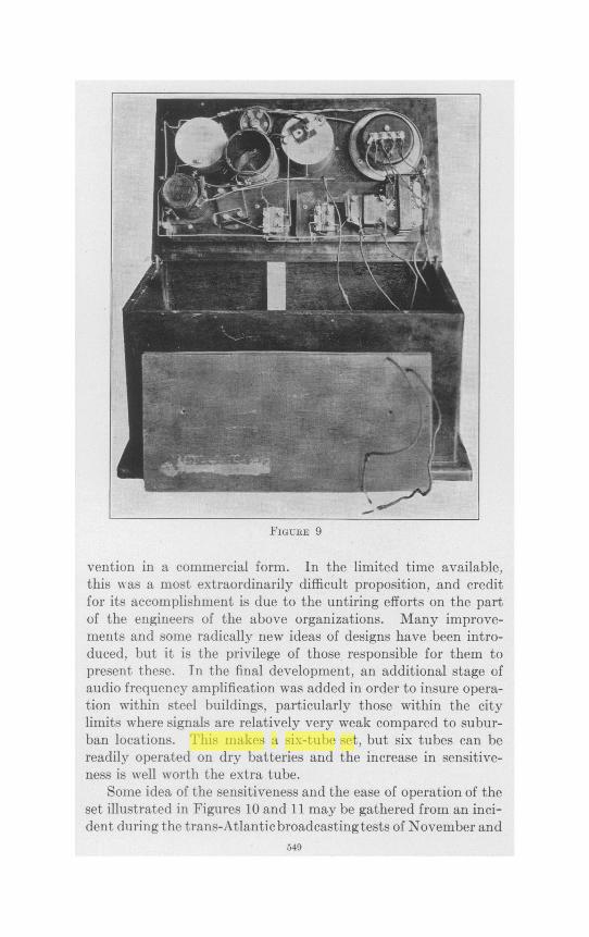
FIGURE 9
vention in a commercial form. In the limited time available,this was a most extraordinarily difficult proposition, and creditfor its accomplishment is due to the untiring efforts on the partof the engineers of the above organizations. Many improve-ments and some radically new ideas of designs have been intro-duced, but it is the privilege of those responsible for them topresent these. In the final development, an additional stage ofaudio frequency amplification was added in order to insure opera-tion within steel buildings, particularly those within the citylimits where signals are relatively very weak compared to subur-ban locations. This makes a six-tube set, but six tubes can bereadily operated on dry batteries and the increase in sensitive-ness is well worth the extra tube.
Some idea of the sensitiveness and the ease of operation of theset illustrated in Figures 10 and 11 may be gathered from an inci-dent during the trans-Atlantic broadcastingtests of November and
549
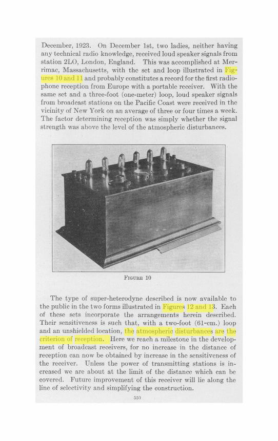
December, 1923. On December 1st, two ladies, neither havingany technical radio knowledge, received loud speaker signals fromstation 2LO, London, England. This was accomplished at Mer-rimac, Massachusetts, with the set and loop illustrated in Fig-ures 10 and 11 and probably constitutes a record for the first radio-phone reception from Europe with a portable receiver. With thesame set and a three-foot (one-meter) loop, loud speaker signalsfrom broadcast stations on the Pacific Coast were received in thevicinity of New York on an average of three or four times a week.The factor determining reception was simply whether the signalstrength was above the level of the atmospheric disturbances.
FIGUREF 10
The type of super-heterodyne described is now available tothe public in the two forms illustrated in Figures 12 and 13. Eachof these sets incorporate the arrangements herein described.Their sensitiveness is such that, with a two-foot (61-cm.) loopand an unshielded location, the atmospheric disturbances are thecriterion of reception. Here we reach a milestone in the develop-ment of broadcast receivers, for no increase in the distance ofreception can now be obtained by increase in the sensitiveness ofthe receiver. Unless the power of transmitting stations is in-creased we are about at the limit of the distance which can becovered. Future improvement of this receiver will lie along theline of selectivity and simplifying the construction.
550

SUMMARY: This paper describes the development of the super-heterodynereceiver from a wartime invention into a commercial form of broadcast re-ceiver apparatus now available to the general public. The success of thedevelopment is due to the low filament consumption vacuum tube and to thereduction in the number of tubes required by self-heterodyning, reflexing, andimprovement in transformer design.
Instances are cited of trans-Atlantic and trans-continental reception ofbroadcast stations by completely portable sets constructed in accordance withthe methods described.
FIGURE 11
551

Li
-
*1 I lSt| :m1:S | ! ! [- l-||I _[- l- i
iI-|
-
FIGIJRE 12
FIGURE 13
.5s2