sunrad - boren · sunrad 02 1.0 sunrad incandescence emitters 1.1 operating principle the sunrad...
TRANSCRIPT
SUNRAD
FRACCARO Officine Termotecniche s.r.l.
Uff. e Stab.: Via Sile, 32 Z.I.
31033 Castelfranco Veneto (TV)
Tel. +39 - 0423 721003 ra
Fax +39 - 0423 493223
www. fraccaro.it
E mail: [email protected]
UNI EN ISO 9001:2008N°9190.OFFR
Agg. 05/2011
Z 02
4 M
S 11
1 E
N

SUNRADINCANDESCENCE
EMETTERSINDEX
1.0 “SUNRAD” INCANDESCENCE EMITTERS1.1 Operating principle1.2 Constructive aspects of SUNRAD2.0 SUNRAD EMITTERS FOR INDUSTRY AND PROCESS APPLICATIONS2.1 Componentry2.2 External dimensions3.0 DESIGNING WITH SUNRAD EMITTERS FOR INDUSTRY3.1 Designing the systems3.2 Distances and distances between centers3.3 Installation modes3.4 Burnt gas exhaust3.5 Functioning3.6 GAS feed3.7 Electrical connections4.0 SUNRAD EMIITTERS FOR PLACES OF WORSHIP4.1 Churches: details and benefits4.2 Componentry and external dimensions4.3 Distances4.4 Installation examples4.5 Ventilation4.6 GAS feed4.7 Electrical connections4.8 Use of mobile supports5.0 THERMIC COMFORT AND THERMOREGULATION5.1 Digital network - Computer Comfort Control SGP200 GEN6.0 TECHNICAL CHARACTERISTICS OF EMITTERS7.0 UNI EN ISO 9001:2008 CERTIFICATES8.0 EC CERTIFICATES
SUNRAD02
1.0 SUNRAD INCANDESCENCE EMITTERS
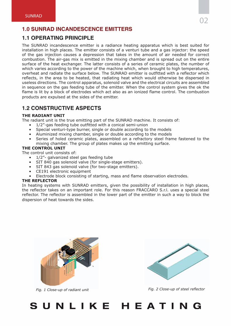
1.1 OPERATING PRINCIPLEThe SUNRAD incandescence emitter is a radiance heating apparatus which is best suited for installation in high places. The emitter consists of a venturi tube and a gas injector: the speed of the gas injection causes a depression that takes in the amount of air needed for correct combustion. The air-gas mix is emitted in the mixing chamber and is spread out on the entire surface of the heat exchanger. The latter consists of a series of ceramic plates, the number of which varies according to the power of the machine which, when brought to high temperatures, overheat and radiate the surface below. The SUNRAD emitter is outfitted with a reflector which reflects, in the area to be heated, that radiating heat which would otherwise be dispersed in useless directions. The control apparatus, solenoid valve and the electrical circuits are assembled in sequence on the gas feeding tube of the emitter. When the control system gives the ok the flame is lit by a block of electrodes which act also as an ionized flame control. The combustion products are expulsed at the sides of the emitter.
1.2 CONSTRUCTIVE ASPECTSTHE RADIANT UNITThe radiant unit is the true emitting part of the SUNRAD machine. It consists of:
• 1/2”-gas feeding tube outfitted with a conical semi-union• Special venturi-type burner, single or double according to the models• Aluminized mixing chamber, single or double according to the models• Series of holed ceramic plates, assembled on a refractory steel frame fastened to the
mixing chamber. The group of plates makes up the emitting surface.THE CONTROL UNITThe control unit consists of:
• 1/2”- galvanized steel gas feeding tube• SIT 840 gas solenoid valve (for single-stage emitters).• SIT 843 gas solenoid valve (for two-stage emitters).• CE191 electronic equipment• Electrode block consisting of starting, mass and flame observation electrodes.
THE REFLECTORIn heating systems with SUNRAD emitters, given the possibility of installation in high places, the reflector takes on an important role. For this reason FRACCARO S.r.l. uses a special steel reflector. The reflector is assembled in the lower part of the emitter in such a way to block the dispersion of heat towards the sides.
Fig. 1 Close-up of radiant unit Fig. 2 Close-up of steel reflector
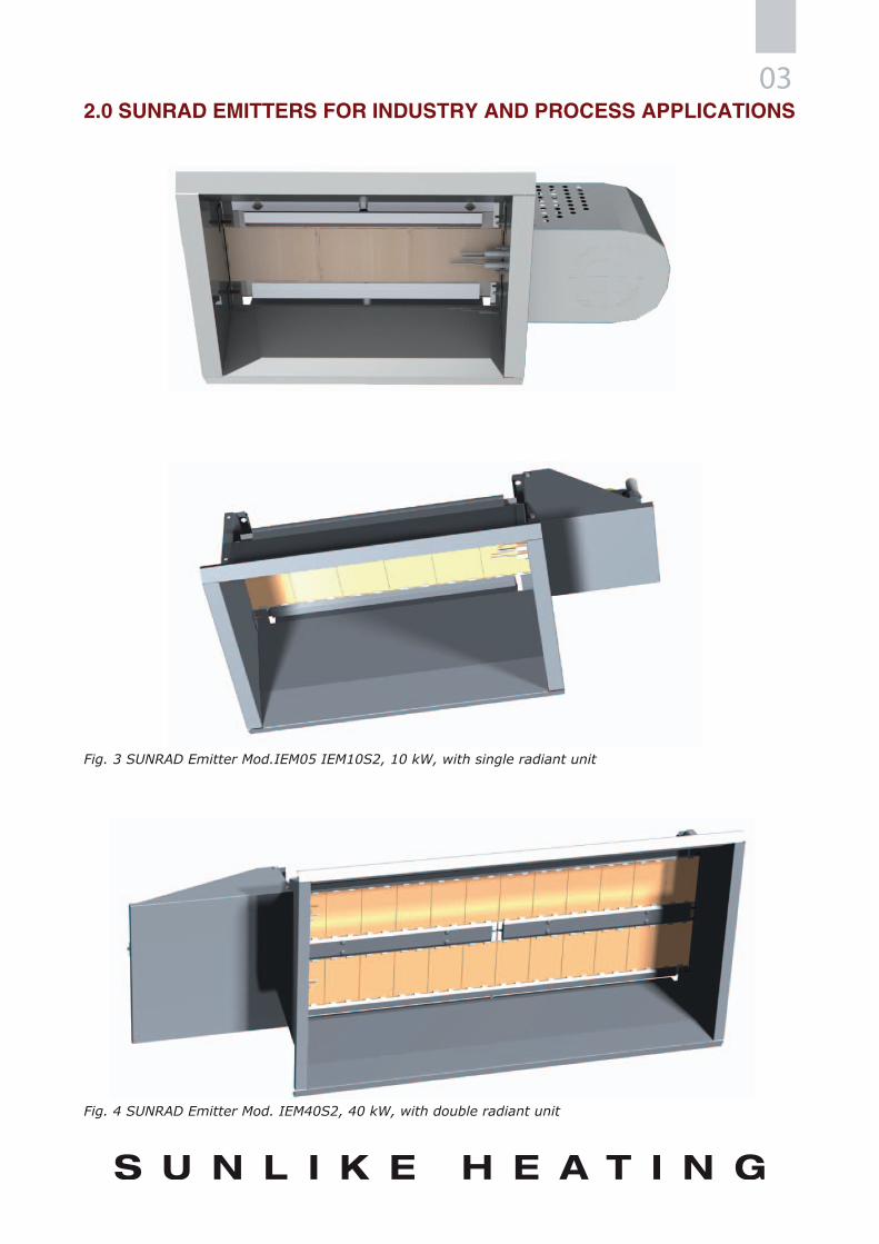
032.0 SUNRAD EMITTERS FOR INDUSTRY AND PROCESS APPLICATIONS
Fig. 3 SUNRAD Emitter Mod.IEM05 IEM10S2, 10 kW, with single radiant unit
Fig. 4 SUNRAD Emitter Mod. IEM40S2, 40 kW, with double radiant unit

SUNRAD04
7
1 3 4
56
2
4 2
1
2.1 COMPONENTRY OF SUNRAD EMITTERS
Fig. 5 SUNRAD Emitters for industry and process applications
Key:1 = Reflectors2 = Aluminized steel mixing chamber3 = Holed ceramic plate4 = Valve protection cover5 = Electrode group: starter, ionization and grounding6 = Gas connection7 = Fastening staff
Tab. 1 Models and thermal power of SUNRAD emitters for industry and process applications
MODEL POWER min / max [kW]
IEM05 5
IEM10 / IEM10 B 10
IEM10S2 / IEM10BS2 7 / 10
IEM20 / IEM20 B 20
IEM20S2 / IEM20BS2 14 / 20
IEM30 30
IEM30S2 25 / 30
IEM35 / IEM35 B 35
IEM35S2 / IEM35BS2 30 / 35
IEM40 40
IEM40S2 28 / 40

05
C
A
B
D
A E
A
B
C
A E
D
F
F
2.2 EXTERNAL DIMENSIONS OF SUNRAD EMITTERS
Fig. 6 External dimensions of SUNRAD emitters for INDUSTRY and PROCESS APPLICATIONS with single radiant unit
Fig. 7 External dimensions of SUNRAD emitters for INDUSTRY and PROCESS APPLICATIONS with double radiant unit
A [mm] B [mm] C [mm] D [mm] E [mm] F [mm]
Models with single radiant unit
IEM05 331 230 652 382 150 400IEM10 - IEM10S2 - IEM10 B 429 323 828 607 189 535IEM20 - IEM20S2 - IEM20 B 429 323 1482 1156 189 1084
IEM30 - IEM30S2 429 353 1743 1522 189 1450IEM35 - IEM35S2 - IEM35 B 429 353 2031 1705 189 1633
Models with double radiant unit
IEM40 - IEM40S2 615 323 1547 1156 375 1084
IEM60 - IEM60S2 615 353 1808 1522 375 1450
Tab. 2 External dimensions of SUNRAD emitters for industry and process applications

SUNRAD06
100°12°30°
45°
60°
8
6
4
2
10 20 30 35 40
3.0 DESIGNING WITH SUNRAD
3.1 DESIGNING SYSTEMS WITH SUNRAD EMITTERSDesigning a heating system first of all requires calculating the loss of heat in the environment to be heated at a certain internal comfort temperature. The thermal power to be installed in the area must be greater than the thermal load of dispersion that has just been calculated.DISTANCES FROM COMBUSTIBLE MATERIAL IN THE RADIATION FIELDThe emitters must be arranged in such a way that in the radiation field, between the radiant surface and the structural elements a surface temperature that could be dangerous is not generated. If there is combustible material to be stored, this condition must be further guaranteed by opportune provisions, such as warning plates and limitation devices and the like.DISTANCES FROM COMBUSTIBLE MATERIAL OUTSIDE THE RADIATION FIELDOutside their radiation field the emitters must be installed far from combustible material which, with a nominal thermal load, cannot have temperatures above 50° C.MINIMUM DISTANCES FROM PEOPLEThe emitters must be arranged in such a way that the people in the radiation field are not exposed to an unhealthy thermal action. Such a principle is assured if the minimum suspension heights indicated in the drawing are respected. The minimum suspension heights indicated are for an air temperature of 10 °C. If there are different air temperatures, the minimum installation height is obtained by using the Correction Factor F1.
H INSTALLATION MINIMUM = H INSTALLATION MINIMUM WITH AIR AT 10°C x F1
Tair [°C] 0 5 10 15
F1 0,9 0,95 1 1,1
Tab. 3 Values of Correction Factor depending on air Temperature F1
It is advisable to respect the values indicated in figure 11, but it is necessary to verify the intake conditions case by case. In the case of emitters with power regulation (2 stages), the correction factor is not necessary for air temperatures over 10°C. In any case the suspension height must never be lower than 4mt.
Fig. 8 Graphical representation of the minimum suggested distance of the emitting surfaces according to the power of the emitter and the inclination angle.
NOMINAL THERMAL LOAD; kW
INC
LIN
ATI
ON
AN
GLE
OF
THE
EMM
ITTE
R
MIN
IMA
L D
ISTA
NC
E FR
OM
EM
ITTI
NG
SU
RFA
CE;
M
EXAMPLEA 20 kW Sunrad, with an inclination angle of 30°, ambient temperature 15°CHm=6.5 mHm,30°=6 mTair 15°C: F1=1.1H=6 x 1.1=6.6m
07
>0,60m
>A
>4,0
0m
>0,6
0m
I
D
H
D
>0,60m
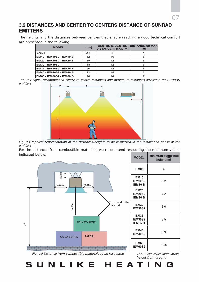
3.2 DISTANCES AND CENTER TO CENTERS DISTANCE OF SUNRAD EMITTERSThe heights and the distances between centres that enable reaching a good technical comfort are presented in the following.
Tab. 4 Height, recommended centre to centre distances and maximum distances advisable for SUNRAD emitters.
Fig. 9 Graphical representation of the distances/heights to be respected in the installation phase of the emittersFor the distances from combustible materials, we recommend respecting the minimum values indicated below.
MODEL Minimum suggested height [m]
IEM05 4
IEM10 IEM10S2 IEM10 B
5,2
IEM20 IEM20S2 IEM20 B
7,2
IEM30 IEM30S2 8,0
IEM35 IEM35S2 IEM35 B
8,5
IEM40 IEM40S2 8,9
IEM60 IEM60S2 10,8
Combustibile material
POLYSTYRENE
CARD BOARD PAPER
Fig. 10 Distance from combustible materials to be respected Tab. 5 Minimum installation height from ground
MODEL H [m] CENTRE to CENTRE DISTANCE (I) MAX [m]
DISTANCE (D) MAX [m]
IEM05 2,5 8 4IEM10 - IEM10S2 - IEM10 B 12 10 5IEM20 - IEM20S2 - IEM20 B 15 12 5IEM30 - IEM30S2 18 12 6IEM35 - IEM35S2 - IEM35 B 20 12 6IEM40 - IEM40S2 - IEM40 B 22 14 7IEM60 - IEM60S2 - IEM60 B 24 14 7

SUNRAD08
3.3 INSTALLATION MODESREGULATING THE ROOM TEMPERATURESUNRAD emitters enable quickly adapting the room temperature to the pre-set values (comfort temperature). The temperature is regulated by using the global probe located inside the area to be heated. It is important to stress that the global probe measures the average value between the air temperature and the radiant temperature, or exactly the thermal effect perceived by man (operating temperature). The regulation and command devices are dislocated in an opportune way inside the building in a central electrical box outfitted with a lock. The homogeneous regulation of the room temperature is not necessary if only work stations or limited areas of the rooms are to be heated.INSTALLATION AREAThe area for installation must have a minimum air change of 10 m3/h for every kW of nominal thermal load installed and a volume not smaller than 10 m3/kW installed (according to the EN 13410 regulation).There are no problems for installation if:1) The area is separated from other areas by walls and ceilings in non-combustible construction materials.2) The construction materials of the area, such as external walls, supports, floors, and parts of the roof, not to mention furniture, are made of non-combustible materials. This is not the case for windows and doors. If such construction elements are in the radiation field, the emitter must be installed according to the specifications in fig. 13.3) The storage of dangerous quantities of combustible material is prohibited.PROHIBITED INSTALLATION AREASThe emitters cannot be installed:a) in houses and offices, nor in areas which do not respect the heights, measurements and/or uses previously mentioned;b) in areas which, after working, accumulate dust or steam which could cause a fire and explosions;c) in areas connected to areas described in point b) by means of openings, or which have openings towards external areas where there are inflammable dust or steam.CEILING INSTALLATIONTo install the SUNRAD incandescence emitters it is necessary to:
• look at the system plan;• assemble the emitter as specified in the instruction and installation manual after having
checked that it is intact;• check on the identification plate that the radiant unit is set to run with the type of gas
available.Following the plan, arrange the anchors to suspend the emitters on the structure in the room. To avoid the dangerous rocking of the emitters it is advisable to suspend them on four slightly spread out points with respect to the radiant unit plant. In any case, it is possible to anchor it only on two points. Hook the chain onto the holes on the radiant unit frame by means of S hooks (or a similar system), lift the radiant units and hook the chains onto the prearranged supports.

093.4 BURNT GAS EXHAUSTBurnt gas exhaust, according to the EN 13410 regulation, can come about in three ways:a) thermal evacuation of the combustion/air mix products;b) mechanical evacuation of the combustion/air mix products;c) natural airflow.It is important that the installation area for the heating machines must have a volume above 10m3 for every kW of installed nominal thermal capacity.
VENTILATION BY MEANS OF THERMAL EVACUATIONThermal evacuation means the natural evacuation due to hot air rising which occurs through openings placed above the SUNRAD emitters. The horizontal distance between one heating device and an opening for stale air evacuation must not be greater than six times the height of the opening if it is on the wall, while it must not be greater than three times the height of the opening if it is on the roof. Ventilation by means of thermal evacuation will be enough if 10 m3/h of stale air per kW of installed thermal capacity come out of the area of installation. When necessary, the evacuation capacity of stale air produced in other ways must be taken into consideration: the surface and the number of openings must therefore be calculated according to the greatest of these air capacities (for calculation methods of the minimum diameter of the openings and for any further study, see the entire text of the EN 13410 regulation).VENTILATION BY MEANS OF MECHANICAL EVACUATIONIn the case of evacuation by means of mechanical ventilation, the intake points must also be placed above the SUNRAD emitters; apart from that only fans that move vertically must be used. The heating machines can be started only when the evacuation of stale air is assured. The horizontal distance between one heating machine and a fan must not be greater than six times the assembly height of the fan if it is on a wall while it must not be greater than three times the assembly height of the fan if it is on a roof. Ventilation by means of mechanical evacuation will be enough if 10 m3/h of stale air per kW of installed thermal capacity comes out of the installation area. When necessary, the evacuation capacity of stale air produced in other ways must be taken into consideration: the capacity of the ventilators is therefore calculated according to the greatest of these air capacities (see EN 13410).VENTILATION BY MEANS OF NATURAL AIR FLOWHeating machines fed by gas can run without any special evacuation system if the combustion products are evacuated to the outside by means of a sufficient change of natural air in the installation area”. This is verified in the following cases:- buildings with natural air change greater than 1.5 volumes per hour;- buildings with a quantity of operative thermal capacity lower than 5 W/m3.

SUNRAD10
1 2A
Amax = 3 x B
B
AIR FEEDThe air feed openings must be placed under the SUNRAD emitters and the sum of the transversal sections not blocked by the air feed openings must not be less than the sum of the transversal sections not blocked by all the evacuation openings. Aerification openings are necessary for air feed. To avoid air draught phenomena, the openings must be located at least 2 m above the floor but below the suspension height of the emitters. Slots and joints that cannot be modified in their section can also be used as aerification openings.
Key:1 Evacuation eye with mechanical ventilation2 Incandescence emitter
Fig. 11 Example of installation: evacuation eye with mechanical ventilation.
3.5 FUNCTIONINGSETTING AT WORKThe systems must be set at work for the first time by FRACCARO S.r.l. or by an authorized assistance centre. In this context all the regulation, command and safety devices must be checked. All of the connections in the electrical circuit must be checked and also the provisions for the protection against exhaust and the preparations for both the aerification openings and the ones for burnt gas/stale air exhaust. The person in charge of the system must be informed on the running of the system.TESTING AND ANNUAL MAINTENANCEDuring testing and maintenance the following tasks must be carried out:1. Cleaning the emitters, in particular the radiant unit in holed ceramic.2. Testing the tightness of the seal of the gas connections.3. Testing the running of the starter device and the flame control.4. Testing the running of the regulation and command devices and of the command apparatus.5. Checking the pressure at the nozzle.6. Checking all the electrical connections.7. Checking the aerification openings and the openings for burnt gas/stale air.8. Checking the indication plates, if present.
In case of anomalies, repairs must be made or parts changed. Repair work on self-regulating parts and flame control devices and other safety devices can only be carried out by the manufacturer or by a technician they put in charge. The expert in charge of maintenance, on the other hand, can change parts or groups of the same type.

11
3 2 1
1
2
3
5
4
6
6
6
3.6 GAS FEEDThe gas feeding system is made by professionally qualified personnel and in compliance with the laws in force in each country it is installed in. Size the gas feeding pipe according to the necessary capacity and pressure, providing for the safety and control devices required by law. The emitters must not be rigidly fastened to the gas piping.
REGULATING THE GAS PRESSUREThe emitters must run with the gas inlet pressure well-regulated in the case of working pressure higher than 30 mbar. A well-designed system does not require a pressure regulator on every single emitter, but a pressure regulator for a group of emitters.
Key:1 Main gas pipe2 Ball valve3 Flexible stainless steel or copper tube with dm. ø 16
3.7 EMITTER ELECTRICAL CONNECTIONSThe electrical cables must be connected as follows:
• Black cable, terminal L1 = feeding phase• Brown cable, terminal T1 = II° stage feeding phase (only for two-stage models)• Blue cable, terminal N = feeding neutral• Grey cable, terminal T2 = burner running signal• Red cable, terminal S3 = burner blocked signal• Yellow-green cable, terminal = grounding conductor
Key:1. Electrical control panel2. Global probe3. 3x1.5 mm2 cable (4x1.5 mm2 for two-stage
emitters)4. L1/N/Pe 50Hz 230V electrical feed5. 2x1.5 mm2 screened cable6. SUNRAD emitter
Fig. 13 Diagram of electrical feed and control of various SUNRAD emitters
Fig. 12 Diagram of the connection of the SUNRAD emitter to the gas network
SUNRAD12
4.0 SUNRAD EMITTERS FOR PLACES OF WORSHIP
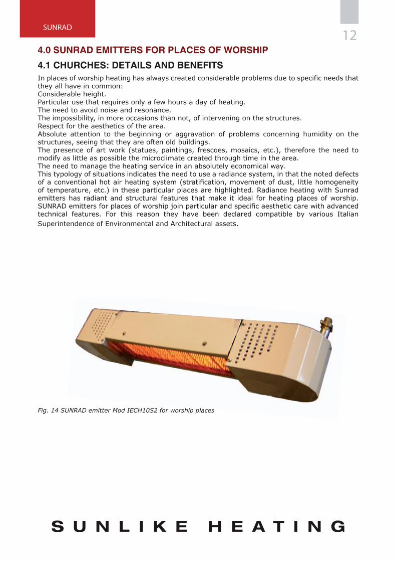
4.1 CHURCHES: DETAILS AND BENEFITSIn places of worship heating has always created considerable problems due to specific needs that they all have in common:Considerable height.Particular use that requires only a few hours a day of heating.The need to avoid noise and resonance.The impossibility, in more occasions than not, of intervening on the structures.Respect for the aesthetics of the area.Absolute attention to the beginning or aggravation of problems concerning humidity on the structures, seeing that they are often old buildings.The presence of art work (statues, paintings, frescoes, mosaics, etc.), therefore the need to modify as little as possible the microclimate created through time in the area.The need to manage the heating service in an absolutely economical way.This typology of situations indicates the need to use a radiance system, in that the noted defects of a conventional hot air heating system (stratification, movement of dust, little homogeneity of temperature, etc.) in these particular places are highlighted. Radiance heating with Sunrad emitters has radiant and structural features that make it ideal for heating places of worship. SUNRAD emitters for places of worship join particular and specific aesthetic care with advanced technical features. For this reason they have been declared compatible by various Italian Superintendence of Environmental and Architectural assets.
Fig. 14 SUNRAD emitter Mod IECH10S2 for worship places

13
A
B
C
1 3 5
4 6
D
2
4.2 COMPONENTRY AND EXTERNAL DIMENSIONS OF SUNRAD EMITTERS
Key:1 = Protection fuse2 = Gas connection3 = Electrical plug4 = Holed ceramic plate5 = Steel mixing chamber6 = Electrode group: starter, ionization and grounding
MODEL POWER min / max [kW] A [mm] B [mm] C [mm] D [mm]
IECH10 101046
200
180
535IECH10S2 7 / 10
IECH20 201596 1084
IECH20S2 14 / 20
IECH30S2 301962 192 1450
IECH30S2 25 / 30
Fig. 15 Componentry and external dimensions of SUNRAD emitters for worship places
Tab. 6 Models, thermal power and external dimensions of SUNRAD emitters for worship places

SUNRAD14
>0,60
>A
4.3 DISTANCES
COMBUSTIBLE MATERIAL
Fig. 16 Recommended distances for the installation of SUNRAD emitters in places of worship, above all if combustible materials are present.
Attention: the minimum distance is purely indicative. The real values need to be verified from case to case based on the type of building and the inclination of the installation. Please, refer to our Technical Department for a correct evaluation.
MODEL Minimum suggested height [m]
IECH10 - IECH10S2 5,2
IECH20 - IECH20S2 7,2
IECH30 - IECH30S2 8,0
Tab. 7 Minimum recommended installation height from the ground
4.4 INSTALLATION EXAMPLES
Fig. 17 SUNRAD emitters in S.Lorenzo in Lucina at Rome

15
1
24
3
4
4
3 2 1
4
4.5 VENTILATIONThe dimensions and the position of the openings for the natural change of air and the evacuation of combustion products must be defined according to the regulation EN 13410 (see paragraph 3.4)
4.6 GAS FEEDThe gas feeding system is made by professionally qualified personnel and in compliance with the laws in force in each country it is installed in. Size the gas feeding pipe according to the necessary capacity and pressure, providing for the safety and control devices required by law. The emitters must not be rigidly fastened to the gas piping.
Key:1 Main gas pipe2 Ball valve3 Flexible stainless steel or copper tube with dm. ø 164 SUNRAD emitters
Fig. 18 Diagram of the connection of the SUNRAD emitter to the gas network
4.7 ELECTRICAL CONNECTIONSThe electrical cables must be connected as follows:
• Black cable, terminal L1 = feeding phase• Brown cable, terminal T1 = II° stage feeding phase (only for two-stage models)• Blue cable, terminal N = feeding neutral (for all electrical network)• Grey cable, terminal T2 = burner running signal• Red cable, terminal S3 = burner blocked signal• Yellow-green cable, terminal = grounding conductor
Key:1. Electrical control panel with two switches for every
emitter2. 3x1.5 mm2 cable (4x1.5 mm2 for two-stage
emitters)3. L1/N/Pe 50Hz 230V electrical feed4. SUNRAD emitters
Fig. 19 Diagram of feed and control of various SUNRAD emitters
SUNRAD16
A B
C
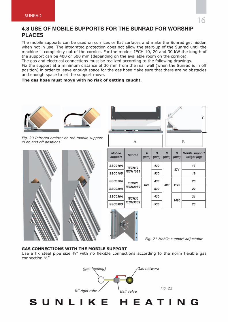
Mobile support Sunrad A
(mm)B
(mm)C
(mm)D
(mm)Mobile support
weight (kg)
SSC010A IECH10 IECH10S2
626
430
300
57417
SSC010B 530 19
SSC020A IECH20 IECH20S2
4301123
20
SSC020B 530 22
SSC030A IECH30 IECH30S2
4301490
21
SSC030B 530 23
(gas feeding)
¾” rigid tube Ball valve
Gas network
4.8 USE OF MOBILE SUPPORTS FOR THE SUNRAD FOR WORSHIP PLACESThe mobile supports can be used on cornices or flat surfaces and make the Sunrad get hidden when not in use. The integrated protection does not allow the start-up of the Sunrad until the machine is completely out of the cornice. For the models IECH 10, 20 and 30 kW the length of the support can be 400 or 500 mm (depending on the available room on the cornice).The gas and electrical connections must be realized according to the following drawings.Fix the support at a minimum distance of 30 mm from the rear wall (when the Sunrad is in off position) in order to leave enough space for the gas hose Make sure that there are no obstacles and enough space to let the support move.The gas hose must move with no risk of getting caught.
Fig. 20 Infrared emitter on the mobile support in on and off positions
GAS CONNECTIONS WITH THE MOBILE SUPPORTUse a fix steel pipe size ¾” with no flexible connections according to the norm flexible gas connection ½”
Fig. 21 Mobile support adjustable
Fig. 22
17
1
3
2
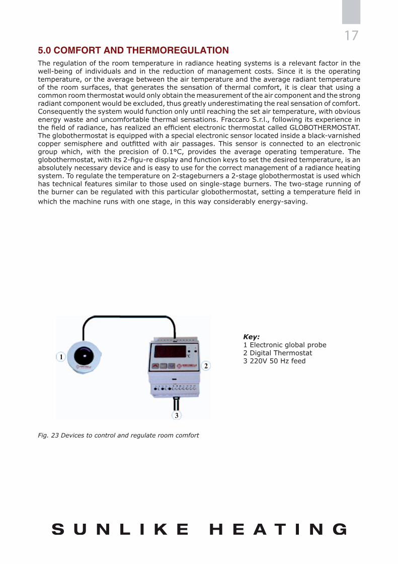
5.0 COMFORT AND THERMOREGULATIONThe regulation of the room temperature in radiance heating systems is a relevant factor in the well-being of individuals and in the reduction of management costs. Since it is the operating temperature, or the average between the air temperature and the average radiant temperature of the room surfaces, that generates the sensation of thermal comfort, it is clear that using a common room thermostat would only obtain the measurement of the air component and the strong radiant component would be excluded, thus greatly underestimating the real sensation of comfort. Consequently the system would function only until reaching the set air temperature, with obvious energy waste and uncomfortable thermal sensations. Fraccaro S.r.l., following its experience in the field of radiance, has realized an efficient electronic thermostat called GLOBOTHERMOSTAT. The globothermostat is equipped with a special electronic sensor located inside a black-varnished copper semisphere and outfitted with air passages. This sensor is connected to an electronic group which, with the precision of 0.1°C, provides the average operating temperature. The globothermostat, with its 2-figu-re display and function keys to set the desired temperature, is an absolutely necessary device and is easy to use for the correct management of a radiance heating system. To regulate the temperature on 2-stageburners a 2-stage globothermostat is used which has technical features similar to those used on single-stage burners. The two-stage running of the burner can be regulated with this particular globothermostat, setting a temperature field in which the machine runs with one stage, in this way considerably energy-saving.
Key:1 Electronic global probe2 Digital Thermostat 3 220V 50 Hz feed
Fig. 23 Devices to control and regulate room comfort

SUNRAD18
16 °C
Mechanical type thermostatElectrical type thermostat.
Fig. 25 Comparison of comfort temperature trends with mechanical thermostat and electronic thermostat.
Time h
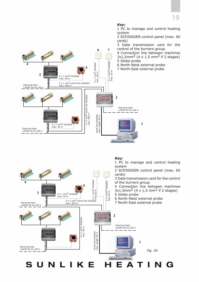
5.1 DIGITAL NETWORK - DIGITAL COMPUTER COMFORT CONTROLFRACCARO S.r.l. designed SCP200 GEN control to manage and control up to a maximum of 1200 SUNRAD emitters. This technology enables significantly to simplify the electrical system as well as the control of the whole system, as it is computer aided.The network controlled by COMPUTER COMFORT CONTROL SCP200 GEN has the following functions:
• Data acquisition from probes inside and outside the building;• Outputs to command relays;• Control of ambient temperature• Facility to program ignition and shut-down times of each generator according to customer’s
requirements;• Real time complete control of the system state, with facility to modify programming at
any time;• Assignment to authorized personnel only of passwords enabling access to functions of
SCP200 GEN;• Control of SUNRAD emitters state;• Subdivision of system into units, enabling zone-control;• 2 outside probes to optimize the ignition times.• Facility for management and control from PC;• An Ethernet connection with Tibbo DS100 Serial server card is available as option.
ELETTRICAL CONNECTION TO THE SCP200 GEN NETWORKSCP200 GEN network consists of the following units:1) SCP200 GEN digital logic control unit for data control and management, up to 60 zones;2) SCP200PER data transmission card (control up to 120 modules), complete with globe-thermostat with the function of data acquisition and transmission to SCP200 GEN digital logic control unit.FRACCARO S.r.l. has also designed FRACCARO-STAT data management software in order to make the time scheduling easier, simplifying the reading of the whole system or single zone state reading and permitting the remote control of activities and parameters.SCP200 GEN network is the best one within the market for the optimization of the thermal power of SUNRAD emitters, according to the building outside and inside variations.
Fig. 24 Comparison of comfort temperature trends between single-stage and two-stage burners
Comfort temperature trend with two-stage type burnerComfort temperature trend with ON –OFF type burner
Time h
Tem
pera
ture
°C
Tem
pera
ture
°C
19
1
3
2
45
6
1
3
2
45
7
Key:1 PC to manage and control heating system2 SCP200GEN control panel (max. 60 cards)3 Data transmission card for the control of the burners group.4 Connection line between machines 3x1,5mm2 (4 x 1,5 mm2 if 2 stages)5 Globe probe6 North-West external probe7 North-East external probe
Key:1 PC to manage and control heating system2 SCP200GEN control panel (max. 60 cards)3 Data transmission card for the control of the burners group.4 Connection line between machines 3x1,5mm2 (4 x 1,5 mm2 if 2 stages)5 Globe probe6 North-West external probe7 North-East external probe
Electrical feedL/N/PE 50 Hz 230 V
2 x
1 m
m2
shie
lded
max
50
m
Electrical feedL/N/PE 50 Hz 230 V
Electrical feedL/N/PE 50 Hz 230 V
4 x
1 m
m2
shie
lded
max
. 50
m
serial
line
shi
elde
dm
ax.
leng
th 3
0 m
4 x 1 mm2 serial line shieldedmax. 500 m
4 x 1 mm2 shieldedmax. 50 m
2 x
1 m
m2
shie
lded
max
50
m
Electrical feedL/N/PE 50 Hz 230 V
4 x 1 mm2 shieldedmax. 50 m
2 x
1 m
m2
serial
line
shi
elde
dm
ax.
500
m
serial
line
shi
elde
dm
ax.
leng
th 3
0 m
Electrical feedL/N/PE 50 Hz 230 V
Electrical feedL/N/PE 50 Hz 230 V
2 x 1 mm2 serial line shieldedmax. 500 m
4 x 1 mm2 shieldedmax. 50 m
2 x
1 m
m2
shie
lded
max
. 50
m
2 x
1 m
m2
shie
lded
max
. 50
m
Fig. 26

SUNRAD20
6.0 TECHNICAL CHARACTERISTICS OF EMITTERSOn
/Off
mod
els
IEM
05IE
M10
IECH
10IE
M20
IECH
20IE
M30
IECH
30IE
M35
IEM
40IE
M60
IEM
10 B
IEM
20 B
IEM
35 B
CE c
ertifi
catio
n nu
mbe
r51
BM20
7151
BM20
7251
BM20
7351
BM20
7251
BM20
73
Max
Pow
er[k
W]
510
2030
3540
6010
2035
Gas
Co
nsum
ptio
n PC
S
G20
[m³s
t/h]
0,48
0,95
1,91
2,86
3,34
3,81
5,72
0,95
1,91
3,34
G25
-G25
.1[m
³st/h
]0,
551,
112,
223,
323,
884,
436,
64
G30
[Kg/
h]0,
360,
731,
462,
182,
552,
914,
360,
731,
462,
55
G31
[Kg/
h]0,
360,
721,
432,
142,
502,
864,
28
Dual
sta
ge M
odel
sIE
M10
S2IE
CH10
S2IE
M20
S2IE
CH20
S2IE
M30
S2IE
CH30
S2IE
M35
S2IE
M40
S2IE
M60
S2IE
M10
S2 B
IEM
20S2
BIE
M35
S2 B
CE c
ertifi
catio
n nu
mbe
r51
BM20
7251
BM20
7351
BM20
7251
BM20
73
Min
/Max
Pow
er[k
W]
7/10
14/2
025
/30
30/3
528
/40
50/6
07/
1014
/20
30/3
5
Gas
Co
nsum
ptio
n PC
S
G20
[m³s
t/h]
0,67
-0,9
51,
33-1
,91
2,38
-2,8
62,
86-3
,34
2,67
-3,8
14,
76-5
,72
0,67
-0,9
51,
33-1
,91
2,86
-3,3
4
G25
-G25
.1[m
³st/h
]0,
78-1
,11
1,55
-2,2
22,
77-3
,32
3,32
-3,8
83,
10-4
,43
5,54
-6,6
4
G30
[K
g/h]
0,51
-0,7
31,
02-1
,46
1,82
-2,1
82,
18-2
,55
2,04
-2,9
13,
64-4
,36
0,51
-0,7
31,
02-1
,46
2,18
-2,5
5
G31
[Kg/
h]0,
50-0
,72
1,00
-1,4
31,
79-2
,14
2,14
-2,5
02,
00-2
,86
3,58
-4,2
8
Burn
er ty
peAt
mos
pher
ic
Gas
con
nect
ion
1/2”
Elec
tricit
y su
pply
[VAC
1N]
230V
Powe
r con
sum
ptio
n[W
att]
9
Elec
trica
l pow
er[A
]0,
04
Wei
ght
[Kg]
8,1
1313
,522
,524
30,5
3433
3955
1322
,533
Vent
uri t
ubes
[n°]
12
1
Com
bust
ion
air
[m³/h
]10
2040
6070
8012
020
4070
Gas
type
I3P;
II2H
3B/P
; I2E
(R)B
; I3+
; I3B
/P; I
2H; I
I2Er
3+; I
I2EL
L3B/
P; II
2H3+
; II2
HS3B
/P; I
I2L3
B/P;
I2E;
II2
E3B/
P/
Electrical feed of Sunrad emitters: 230 V - 50 HzGas inlet pressure: 20 mbar for G20; 28/30 or 50 mbar for G30For IEM40 only: 30 mbar for G20.Working Temperature: -20 ÷ 60 °CIdentification plate: As in the normative CEE/90/396SUNRAD emitters can also be fed by combustible gasses G25 (methane-azote) and G31 (propane).

217.0 UNI EN ISO 9001:2008 CERTIFICATES
8.0 EC CERTIFICATES

SUNRAD22
23NOTES . . . . . . . . . . . . . . . . . . . . . . . . . . . . . . . . . . . . . . . . . . . . . . . . . . . . . . . . . . . . . . . . . . . . . . . . . . . . . . . . . . . . . . . . . . . . . . . . . . . . . . . . . . . . . . . . . . . . . . . . . . . . . . . . . . . . . . . . . . . . . . . . . . . . . . . . . . . . . . . . . . . . . . . . . . . . . . . . . . . . . . . . . . . . . . . . . . . . . . . . . . . . . . . . . . . . . . . . . . . . . . . . . . . . . . . . . . . . . . . . . . . . . . . . . . . . . . . . . . . . . . . . . . . . . . . . . . . . . . . . . . . . . . . . . . . . . . . . . . . . . . . . . . . . . . . . . . . . . . . . . . . . . . . . . . . . . . . . . . . . . . . . . . . . . . . . . . . . . . . . . . . . . . . . . . . . . . . . . . . . . . . . . . . . . . . . . . . . . . . . . . . . . . . . . . . . . . . . . . . . . . . . . . . . . . . . . . . . . . . . . . . . . . . . . . . . . . . . . . . . . . . . . . . . . . . . . . . . . . . . . . . . . . . . . . . . . . . . . . . . . . . . . . . . . . . . . . . . . . . . . . . . . . . . . . . . . . . . . . . . . . . . . . . . . . . . . . . . . . . . . . . . . . . . . . . . . . . . . . . . . . . . . . . . . . . . . . . . . . . . . . . . . . . . . . . . . . . . . . . . . . . . . . . . . . . . . . . . . . . . . . . . . . . . . . . . . . . . . . . . . . . . . . . . . . . . . . . . . . . . . . . . . . . . . . . . . . . . . . . . . . . . . . . . . . . . . . . . . . . . . . . . . . . . . . . . . . . . . . . . . . . . . . . . . . . . . . . . . . . . . . . . . . . . . . . . . . . . . . . . . . . . . . . . . . . . . . . . . . . . . . . . . . . . . . . . . . . . . . . . . . . . . . . . . . . . . . . . . . . . . . . . . . . . . . . . . . . . . . . . . . . . . . . . . . . . . . . . . . . . . . . . . . . . . . . . . . . . . . . . . . . . . . . . . . . . . . . . . . . . . . . . . . . . . . . . . . . . . . . . . . . . . . . . . . . . . . . . . . . . . . . . . . . . . . . . . . . . . . . . . . . . . . . . . . . . . . . . . . . . . . . . . . . . . . . . . . . . . . . . . . . . . . . . . . . . . . . . . . . . . . . . . . . . . . . . . . . . . . . . . . . . . . . . . . . . . . . . . . . . . . . . . . . . . . . . . . . . . . . . . . . . . . . . . . . . . . . . . . . . . . . . . . . . . . . . . . . . . . . . . . . . . . . . . . . . . . . . . . . . . . . . . . . . . . . . . . . . . . . . . . . . . . . . . . . . . . . . . . . . . . . . . . . . . . . . . . . . . . . . . . . . . . . . . . . . . . . . . . . . . . . . . . . . . . . . . . . . . . . . . . . . . . . . . . . . . . . . . . . . . . . . . . . . . . . . . . . . . . . . . . . . . . . . . . . . . . . . . . . . . . . . . . . . . . . . . . . . . . . . . . . . . . . . . . . . . . . . . . . . . . . . . . . . . . . . . . . . . . . . . . . . . . . . . . . . . . . . . . . . . . . . . . . . . . . . . . . . . . . . . . . . . . . . . . . . . . . . . . . . . . . . . . . . . . . . . . . . . . . . . . . . . . . . . . . . . . . . . . . . . . . . . . . . . . . . . . . . . . . . . . . . . . . . . . . . . . . . . . . . . . . . . . . . . . . . . . . . . . . . . . . . . . . . . . . . . . . . . . . . . . . . . . . . . . . . . . . . . . . . . . . . . . . . . . . . . . . . . . . . . . . . . . . . . . . . . . . . . . . . . . . . . . . . . . . . . . . . . . . . . . . . . . . . . . . . . . . . . . . . . . . . . . . . . . . . . . . . . . . . . . . . . . . . . . . . . . . . . . . . . . . . . . . . . . . . . . . . . . . . . . . . . . . . . . . . . . . . . . . . . . . . . . . . . . . . . . . . . . . . . . . . . . . . . . . . . . . . . . . . . . . . . . . . . . . . . . . . . . . . . . . . . . . . . . . . . . . . . . . . . . . . . . . . . . . . . . . . . . . . . . . . . . . . . . . . . . . . . . . . . . . . . . . . . . . . . . . . . . . . . . . . . . . . . . . . . . . . . . . . . . . . . . . . . . . . . . . . . . . . . . . . . . . . . . . . . . . . . .

SUNRAD24
The illustrations and descriptions provided in this manual are not binding. FRACCARO S.r.l. reserves the right, in any moment, to change them whenever it deems necessary due to technical, constructive or commercial needs. Furthermore, FRACCARO S.r.l. reserves the right to vary the data reported in the tables without previous warning for the purpose of continuously improving
its products.

SUNRAD
FRACCARO Officine Termotecniche s.r.l.
Uff. e Stab.: Via Sile, 32 Z.I.
31033 Castelfranco Veneto (TV)
Tel. +39 - 0423 721003 ra
Fax +39 - 0423 493223
www. fraccaro.it
E mail: [email protected]
UNI EN ISO 9001:2008N°9190.OFFR
Agg. 05/2011
Z 02
4 M
S 11
1 E
N