sunny boy/windy boy/sunny tripower - firmware update...
TRANSCRIPT
NG_UpdSD-TB-en-32 | Version 3.2 EN
Firmware Update with SD CardSUNNY BOYWINDY BOYSUNNY TRIPOWERTechnical Description

SMA Solar Technology AG Table of Contents
Technical Description NG_UpdSD-TB-en-32 3
Table of Contents1 Information on this Manual. . . . . . . . . . . . . . . . . . . . . . . . . 51.1 Validity . . . . . . . . . . . . . . . . . . . . . . . . . . . . . . . . . . . . . . . . . . . . 51.2 Target Group . . . . . . . . . . . . . . . . . . . . . . . . . . . . . . . . . . . . . . . 51.3 Symbols Used . . . . . . . . . . . . . . . . . . . . . . . . . . . . . . . . . . . . . . . 62 Safety Precautions . . . . . . . . . . . . . . . . . . . . . . . . . . . . . . . . 72.1 General Safety Precautions . . . . . . . . . . . . . . . . . . . . . . . . . . . . 72.2 Special Safety Precautions for STP 8000TL-10/
STP 10000TL-10/STP 12000TL-10/STP 15000TL-10/STP 17000TL-10. . . . . . . . . . . . . . . . . . . . . . . . . . . . . . . . . . . . . 7
2.2.1 Beeping inverters of type STP 8000TL-10/STP 10000TL-10/STP 12000TL-10/STP 15000TL-10/STP 17000TL-10 . . . . . . . . . . . . . . . . . . .8
3 Preparing the SD Card. . . . . . . . . . . . . . . . . . . . . . . . . . . . . 94 Updating the Firmware . . . . . . . . . . . . . . . . . . . . . . . . . . . 114.1 Inserting the SD Card . . . . . . . . . . . . . . . . . . . . . . . . . . . . . . . . 114.1.1 SB 3000TL-20/SB 4000TL-20/SB 5000TL-20/WB 3600TL-20/
WB 5000TL-20 . . . . . . . . . . . . . . . . . . . . . . . . . . . . . . . . . . . . . . . . . . . . . . . 114.1.2 SB 2500TLST-21/SB 3000TLST-21/SB 3000TL-21/SB 3600TL-21/
SB 4000TL-21/SB 5000TL-21/WB 3000TL-21/ WB 3600TL-21/WB 4000TL-21/WB 5000TL-21 . . . . . . . . . . . . . . . . . . . . . . . . . . . . . . . . . 17
4.1.3 SB 2000HF-30/SB 2500HF-30/SB 3000HF-30. . . . . . . . . . . . . . . . . . . . . 234.1.4 STP 8000TL-10/STP 10000TL-10/STP 12000TL-10/STP 15000TL-10/
STP 17000TL-10 . . . . . . . . . . . . . . . . . . . . . . . . . . . . . . . . . . . . . . . . . . . . . . 274.1.5 STP 15000TLHE-10/STP 15000TLEE-10/STP 20000TLHE-10/
STP 20000TLEE-10 . . . . . . . . . . . . . . . . . . . . . . . . . . . . . . . . . . . . . . . . . . . . 324.2 Update Messages. . . . . . . . . . . . . . . . . . . . . . . . . . . . . . . . . . . 37
Table of Contents SMA Solar Technology AG
4 NG_UpdSD-TB-en-32 Technical Description
4.3 Removing the SD Card . . . . . . . . . . . . . . . . . . . . . . . . . . . . . . . 404.3.1 SB 3000TL-20/SB 4000TL-20/SB 5000TL-20/WB 3600TL-20/
WB 5000TL-20 . . . . . . . . . . . . . . . . . . . . . . . . . . . . . . . . . . . . . . . . . . . . . . . 404.3.2 SB 2000HF-30/SB 2500HF-30/SB 3000HF-30. . . . . . . . . . . . . . . . . . . . . 404.3.3 SB 2500TLST-21/SB 3000TLST-21/SB 3000TL-21/SB 3600TL-21/
SB 4000TL-21/SB 5000TL-21/STP 8000TL-10/STP 10000TL-10/STP 12000TL-10/STP 15000TL-10/STP 17000TL-10/ STP 15000TLHE-10/STP 15000TLEE-10/STP 20000TLHE-10/STP 20000TLHE-10/WB 3000TL-21/WB 3600TL-21/WB 4000TL-21/WB 5000TL-21 . . . . . . . . . . . . . . . . . . . . . . . . . . . . . . . . . . . . . . . . . . . . . . . 41
4.4 Redetecting the Inverter in the Communication Device . . . . . . . 415 Checking the Current Firmware Status. . . . . . . . . . . . . . . 426 Contact . . . . . . . . . . . . . . . . . . . . . . . . . . . . . . . . . . . . . . . . 43
SMA Solar Technology AG Information on this Manual
Technical Description NG_UpdSD-TB-en-32 5
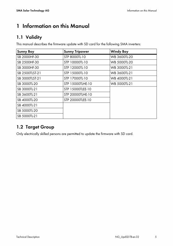
1 Information on this Manual1.1 ValidityThis manual describes the firmware update with SD card for the following SMA inverters:
1.2 Target GroupOnly electrically skilled persons are permitted to update the firmware with SD card.
Sunny Boy Sunny Tripower Windy BoySB 2000HF-30 STP 8000TL-10 WB 3600TL-20SB 2500HF-30 STP 10000TL-10 WB 5000TL-20SB 3000HF-30 STP 12000TL-10 WB 3000TL-21SB 2500TLST-21 STP 15000TL-10 WB 3600TL-21SB 3000TLST-21 STP 17000TL-10 WB 4000TL-21SB 3000TL-20 STP 15000TLHE-10 WB 5000TL-21SB 3000TL-21 STP 15000TLEE-10SB 3600TL-21 STP 20000TLHE-10SB 4000TL-20 STP 20000TLEE-10SB 4000TL-21SB 5000TL-20SB 5000TL-21
Information on this Manual SMA Solar Technology AG
6 NG_UpdSD-TB-en-32 Technical Description
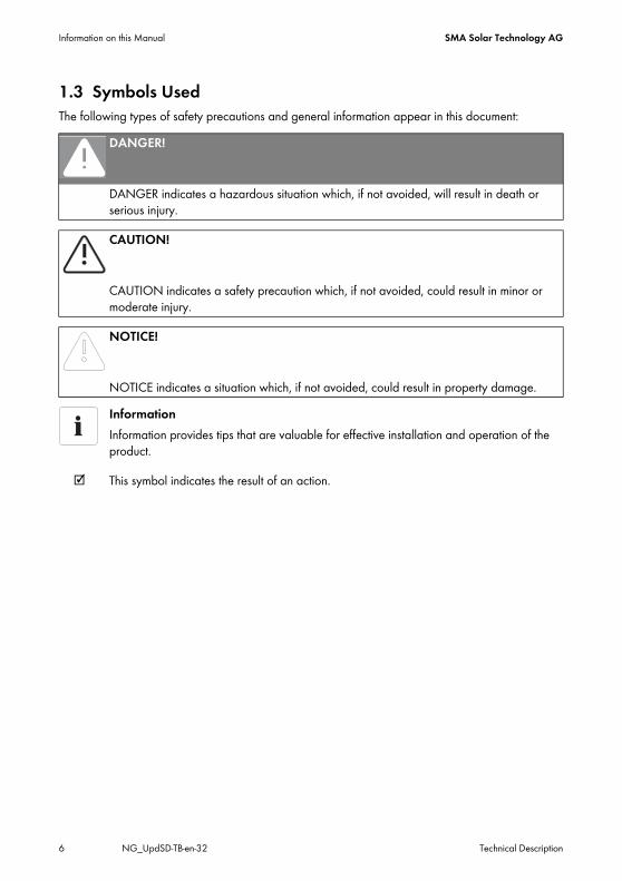
1.3 Symbols UsedThe following types of safety precautions and general information appear in this document:
DANGER!
DANGER indicates a hazardous situation which, if not avoided, will result in death or serious injury.
CAUTION!
CAUTION indicates a safety precaution which, if not avoided, could result in minor or moderate injury.
NOTICE!
NOTICE indicates a situation which, if not avoided, could result in property damage.InformationInformation provides tips that are valuable for effective installation and operation of the product.
☑ This symbol indicates the result of an action.
SMA Solar Technology AG Safety Precautions
Technical Description NG_UpdSD-TB-en-32 7
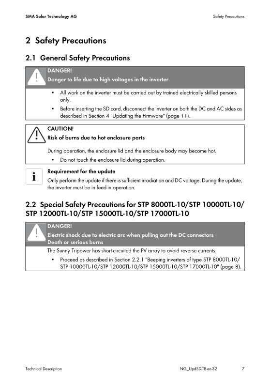
2 Safety Precautions2.1 General Safety Precautions
2.2 Special Safety Precautions for STP 8000TL-10/STP 10000TL-10/STP 12000TL-10/STP 15000TL-10/STP 17000TL-10
DANGER!Danger to life due to high voltages in the inverter
• All work on the inverter must be carried out by trained electrically skilled persons only.
• Before inserting the SD card, disconnect the inverter on both the DC and AC sides as described in Section 4 "Updating the Firmware" (page 11).
CAUTION!Risk of burns due to hot enclosure parts
During operation, the enclosure lid and the enclosure body may become hot.• Do not touch the enclosure lid during operation.
Requirement for the updateOnly perform the update if there is sufficient irradiation and DC voltage. During the update, the inverter must be in feed-in operation.
DANGER!Electric shock due to electric arc when pulling out the DC connectors Death or serious burnsThe Sunny Tripower has short-circuited the PV array to avoid reverse currents.
• Proceed as described in Section 2.2.1 "Beeping inverters of type STP 8000TL-10/STP 10000TL-10/STP 12000TL-10/STP 15000TL-10/STP 17000TL-10" (page 8).
Safety Precautions SMA Solar Technology AG
8 NG_UpdSD-TB-en-32 Technical Description
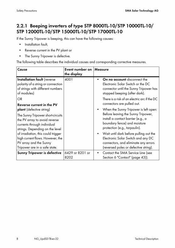
2.2.1 Beeping inverters of type STP 8000TL-10/STP 10000TL-10/STP 12000TL-10/STP 15000TL-10/STP 17000TL-10If the Sunny Tripower is beeping, this can have the following causes:
• Installation fault,• Reverse current in the PV plant or• The Sunny Tripower is defective.
The following table describes the individual causes and corresponding corrective measures.Cause Event number on
the displayMeasure
Installation fault (reverse polarity of a string or connection of strings with different numbers of modules)ORReverse current in the PV plant (defective string)The Sunny Tripower short-circuits the PV array to avoid reverse currents through individual strings. Depending on the level of irradiation, this could trigger high current flows. However, the PV array and the Sunny Tripower are in a safe state.
4001 • On no account disconnect the Electronic Solar Switch or the DC connector until the Sunny Tripower has stopped beeping (after dark).There is a risk of an electric arc if the DC connectors are pulled out.
• When the Sunny Tripower is left open: Before leaving the Sunny Tripower, install a contact barrier (e.g., a boundary fence) and moisture protection (e.g., tarpaulin).
• Wait until dark before pulling out the Electronic Solar Switch and any DC connectors, and eliminate any errors (reversed poles or defective string).
Sunny Tripower is defective 6429 or 8201 or 8202
• Contact the SMA Service Line (see Section 6 "Contact" (page 43)).
SMA Solar Technology AG Preparing the SD Card
Technical Description NG_UpdSD-TB-en-32 9
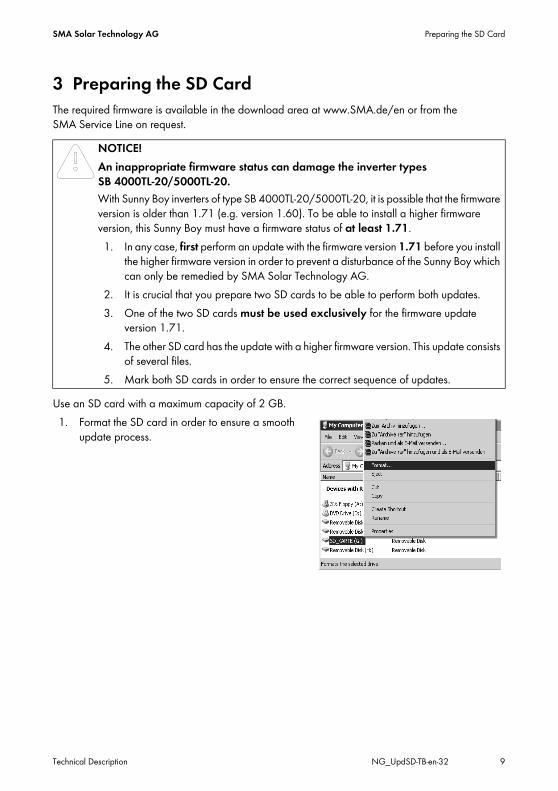
3 Preparing the SD CardThe required firmware is available in the download area at www.SMA.de/en or from the SMA Service Line on request.
Use an SD card with a maximum capacity of 2 GB.1. Format the SD card in order to ensure a smooth
update process.
NOTICE!An inappropriate firmware status can damage the inverter types SB 4000TL-20/5000TL-20.With Sunny Boy inverters of type SB 4000TL-20/5000TL-20, it is possible that the firmware version is older than 1.71 (e.g. version 1.60). To be able to install a higher firmware version, this Sunny Boy must have a firmware status of at least 1.71.1. In any case, first perform an update with the firmware version 1.71 before you install
the higher firmware version in order to prevent a disturbance of the Sunny Boy which can only be remedied by SMA Solar Technology AG.
2. It is crucial that you prepare two SD cards to be able to perform both updates.3. One of the two SD cards must be used exclusively for the firmware update
version 1.71.4. The other SD card has the update with a higher firmware version. This update consists
of several files.5. Mark both SD cards in order to ensure the correct sequence of updates.

Preparing the SD Card SMA Solar Technology AG
10 NG_UpdSD-TB-en-32 Technical Description
2. Select "FAT32" under the file system and click "Start".
3. Copy the sub-directory "Update" (download file) with all available files from the folder "_Firmware_Update Vx.xx" to the SD card.
4. Eject the SD card from the card reader
5. For SB 4000TL-20/5000TL-20:If you are sure that the inverter has at least firmware version 1.71 or higher, then you do not have to carry out the following steps.– Repeat steps 1 and 2 with the second SD card
for the firmware version 1.71.– Copy the sub-directory "Update" (download
file) with the file from the folder "_Firmware_Update V1.71" to the SD card.
– Eject the second SD card from the card reader.– Mark the second SD card in order to preserve
the correct sequence for the update.☑ The SD card can now be used for a firmware update in the inverter.
SMA Solar Technology AG Updating the Firmware
Technical Description NG_UpdSD-TB-en-32 11
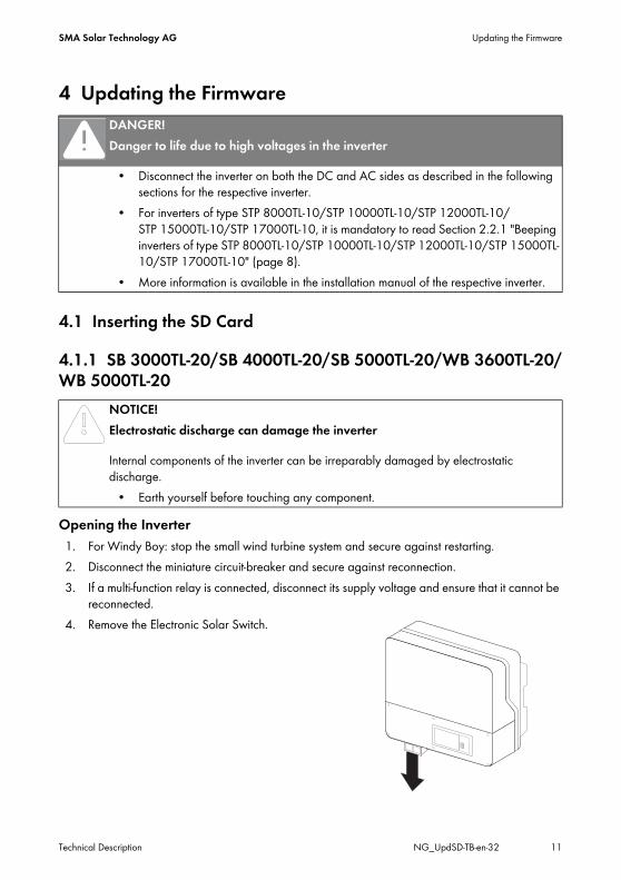
4 Updating the Firmware
4.1 Inserting the SD Card
4.1.1 SB 3000TL-20/SB 4000TL-20/SB 5000TL-20/WB 3600TL-20/WB 5000TL-20
Opening the Inverter1. For Windy Boy: stop the small wind turbine system and secure against restarting.2. Disconnect the miniature circuit-breaker and secure against reconnection.3. If a multi-function relay is connected, disconnect its supply voltage and ensure that it cannot be
reconnected.4. Remove the Electronic Solar Switch.
DANGER!Danger to life due to high voltages in the inverter
• Disconnect the inverter on both the DC and AC sides as described in the following sections for the respective inverter.
• For inverters of type STP 8000TL-10/STP 10000TL-10/STP 12000TL-10/STP 15000TL-10/STP 17000TL-10, it is mandatory to read Section 2.2.1 "Beeping inverters of type STP 8000TL-10/STP 10000TL-10/STP 12000TL-10/STP 15000TL-10/STP 17000TL-10" (page 8).
• More information is available in the installation manual of the respective inverter.
NOTICE!Electrostatic discharge can damage the inverter
Internal components of the inverter can be irreparably damaged by electrostatic discharge.
• Earth yourself before touching any component.
Updating the Firmware SMA Solar Technology AG
12 NG_UpdSD-TB-en-32 Technical Description
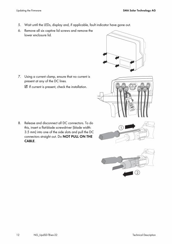
5. Wait until the LEDs, display and, if applicable, fault indicator have gone out.6. Remove all six captive lid screws and remove the
lower enclosure lid.
7. Using a current clamp, ensure that no current is present at any of the DC lines. ☑ If current is present, check the installation.
8. Release and disconnect all DC connectors. To do this, insert a flat-blade screwdriver (blade width: 3.5 mm) into one of the side slots and pull the DC connectors straight out. Do NOT PULL ON THE CABLE.
SMA Solar Technology AG Updating the Firmware
Technical Description NG_UpdSD-TB-en-32 13
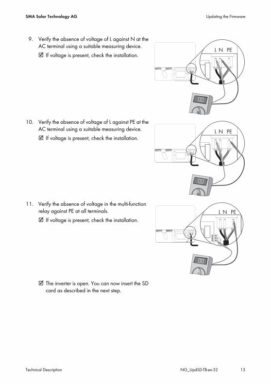
9. Verify the absence of voltage of L against N at the AC terminal using a suitable measuring device. ☑ If voltage is present, check the installation.
10. Verify the absence of voltage of L against PE at the AC terminal using a suitable measuring device. ☑ If voltage is present, check the installation.
11. Verify the absence of voltage in the multi-function relay against PE at all terminals.☑ If voltage is present, check the installation.
☑ The inverter is open. You can now insert the SD card as described in the next step.
Updating the Firmware SMA Solar Technology AG
14 NG_UpdSD-TB-en-32 Technical Description
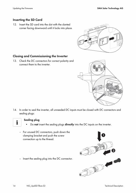
Inserting the SD Card12. Insert the SD card into the slot with the slanted
corner facing downward until it locks into place.
Closing and Commissioning the Inverter13. Check the DC connectors for correct polarity and
connect them to the inverter.
14. In order to seal the inverter, all unneeded DC inputs must be closed with DC connectors and sealing plugs:
– For unused DC connectors, push down the clamping bracket and push the screw connection up to the thread.
– Insert the sealing plug into the DC connector.
Sealing plug• Do not insert the sealing plugs directly into the DC inputs on the inverter.
+
1
2
+
SMA Solar Technology AG Updating the Firmware
Technical Description NG_UpdSD-TB-en-32 15
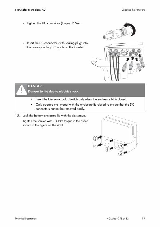
– Tighten the DC connector (torque: 2 Nm).
– Insert the DC connectors with sealing plugs into the corresponding DC inputs on the inverter.
15. Lock the bottom enclosure lid with the six screws.Tighten the screws with 1.4 Nm torque in the order shown in the figure on the right.
DANGER!Danger to life due to electric shock.
• Insert the Electronic Solar Switch only when the enclosure lid is closed. • Only operate the inverter with the enclosure lid closed to ensure that the DC
connectors cannot be removed easily.
+
Updating the Firmware SMA Solar Technology AG
16 NG_UpdSD-TB-en-32 Technical Description
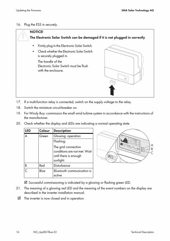
16. Plug the ESS in securely.
17. If a multi-function relay is connected, switch on the supply voltage to the relay.18. Switch the miniature circuit-breaker on.19. For Windy Boy: commission the small wind turbine system in accordance with the instructions of
the manufacturer.20. Check whether the display and LEDs are indicating a normal operating state.
☑ Successful commissioning is indicated by a glowing or flashing green LED.21. The meaning of a glowing red LED and the meaning of the event numbers on the display are
described in the inverter installation manual.☑ The inverter is now closed and in operation.
NOTICE!The Electronic Solar Switch can be damaged if it is not plugged in correctly
• Firmly plug in the Electronic Solar Switch. • Check whether the Electronic Solar Switch
is securely plugged in.The handle of the Electronic Solar Switch must be flush with the enclosure.
LED Colour DescriptionA Green Glowing: operation
Flashing:The grid connection conditions are not met. Wait until there is enough sunlight.
B Red DisturbanceC Blue Bluetooth communication is
active

SMA Solar Technology AG Updating the Firmware
Technical Description NG_UpdSD-TB-en-32 17
4.1.2 SB 2500TLST-21/SB 3000TLST-21/SB 3000TL-21/SB 3600TL-21/SB 4000TL-21/SB 5000TL-21/WB 3000TL-21/ WB 3600TL-21/WB 4000TL-21/WB 5000TL-21
Opening the Inverter1. For Windy Boy: stop the small wind turbine system and secure against restarting.2. Disconnect the miniature circuit-breaker and secure against reconnection.3. If a multi-function relay is connected, disconnect its supply voltage and ensure that it cannot be
reconnected.4. Remove the ESS.
5. Loosen all six captive screws and remove the lower enclosure lid. Use an Allen key (AF 3) to do this.
NOTICE!Electrostatic discharge can damage the inverter
Internal components of the inverter can be irreparably damaged by electrostatic discharge.
• Earth yourself before touching any component.
Updating the Firmware SMA Solar Technology AG
18 NG_UpdSD-TB-en-32 Technical Description
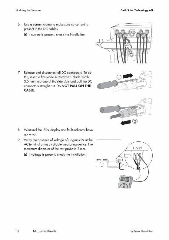
6. Use a current clamp to make sure no current is present in the DC cables. ☑ If current is present, check the installation.
7. Release and disconnect all DC connectors. To do this, insert a flat-blade screwdriver (blade width: 3.5 mm) into one of the side slots and pull the DC connectors straight out. Do NOT PULL ON THE CABLE.
8. Wait until the LEDs, display and fault indicator have gone out.
9. Verify the absence of voltage of L against N at the AC terminal using a suitable measuring device. The maximum diameter of the test probe is 2 mm.☑ If voltage is present, check the installation.
SMA Solar Technology AG Updating the Firmware
Technical Description NG_UpdSD-TB-en-32 19
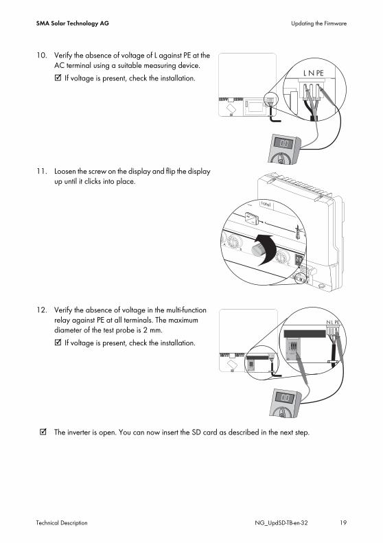
10. Verify the absence of voltage of L against PE at the AC terminal using a suitable measuring device. ☑ If voltage is present, check the installation.
11. Loosen the screw on the display and flip the display up until it clicks into place.
12. Verify the absence of voltage in the multi-function relay against PE at all terminals. The maximum diameter of the test probe is 2 mm.☑ If voltage is present, check the installation.
☑ The inverter is open. You can now insert the SD card as described in the next step.
79
ON
E
79
ON
1 32Imax = 1A
Ima
x =
1A
1 32Imax = 1A
Ima
x =
1A
N L PE

Updating the Firmware SMA Solar Technology AG
20 NG_UpdSD-TB-en-32 Technical Description
Inserting the SD Card13. Insert the SD card into the slot with the slanted
corner facing downward until it locks into place.
14. Flip down the display and tighten with screws.Closing and Commissioning the Inverter15. Check the DC connectors for correct polarity and
connect them to the inverter. ☑ The DC connectors click audibly into place.
16. If you do not need all DC inputs on the inverter, seal the enclosure with DC connectors and sealing plugs:
– For unused DC connectors, push down the clamping bracket and push the screw connection up to the thread.
– Insert the sealing plug into the DC connector.
Sealing plug• Do not insert the sealing plugs directly into the DC inputs on the inverter.
+
1
2
+
SMA Solar Technology AG Updating the Firmware
Technical Description NG_UpdSD-TB-en-32 21
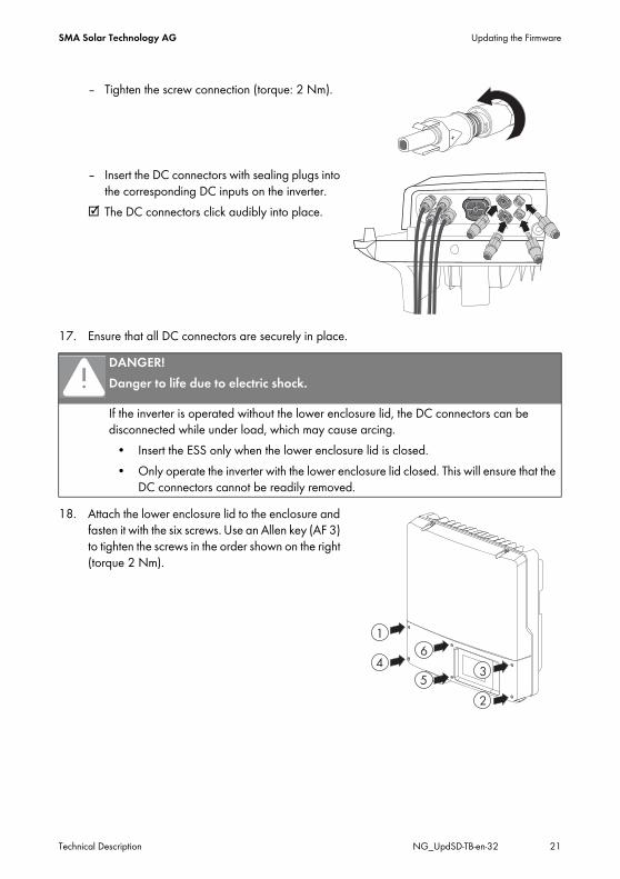
– Tighten the screw connection (torque: 2 Nm).
– Insert the DC connectors with sealing plugs into the corresponding DC inputs on the inverter.
☑ The DC connectors click audibly into place.
17. Ensure that all DC connectors are securely in place.
18. Attach the lower enclosure lid to the enclosure and fasten it with the six screws. Use an Allen key (AF 3) to tighten the screws in the order shown on the right (torque 2 Nm).
DANGER!Danger to life due to electric shock.
If the inverter is operated without the lower enclosure lid, the DC connectors can be disconnected while under load, which may cause arcing.
• Insert the ESS only when the lower enclosure lid is closed. • Only operate the inverter with the lower enclosure lid closed. This will ensure that the
DC connectors cannot be readily removed.
+
6
53
2
4
1

Updating the Firmware SMA Solar Technology AG
22 NG_UpdSD-TB-en-32 Technical Description
19. Plug the ESS in securely.
20. If a multi-function relay is connected, switch on the supply voltage to the relay.21. Switch the miniature circuit-breaker on.22. For Windy Boy: commission the small wind turbine system in accordance with the instructions of
the manufacturer.23. If a multi-function relay is connected, switch on the supply voltage to the relay.
☑ Green LED is glowing: commissioning successful.or☑ Green LED is flashing if DC voltage is insufficient: grid connection conditions have not yet
been reached. Wait for sufficient DC voltage.or☑ Red LED is glowing: a disturbance has occurred. Locate and eliminate the fault (see the
inverter installation manual).
NOTICE!The ESS can be damaged if it is not connected correctly.
• Plug the ESS in securely. The handle of the Electronic Solar Switch must be flush with the enclosure.
• Check that the ESS is securely in place.
SMA Solar Technology AG Updating the Firmware
Technical Description NG_UpdSD-TB-en-32 23
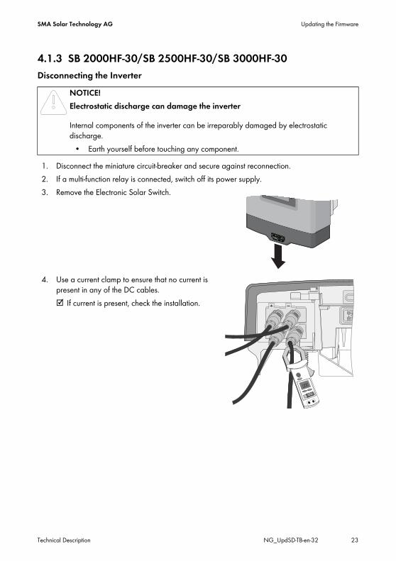
4.1.3 SB 2000HF-30/SB 2500HF-30/SB 3000HF-30Disconnecting the Inverter
1. Disconnect the miniature circuit-breaker and secure against reconnection.2. If a multi-function relay is connected, switch off its power supply.3. Remove the Electronic Solar Switch.
4. Use a current clamp to ensure that no current is present in any of the DC cables.☑ If current is present, check the installation.
NOTICE!Electrostatic discharge can damage the inverter
Internal components of the inverter can be irreparably damaged by electrostatic discharge.
• Earth yourself before touching any component.
Updating the Firmware SMA Solar Technology AG
24 NG_UpdSD-TB-en-32 Technical Description
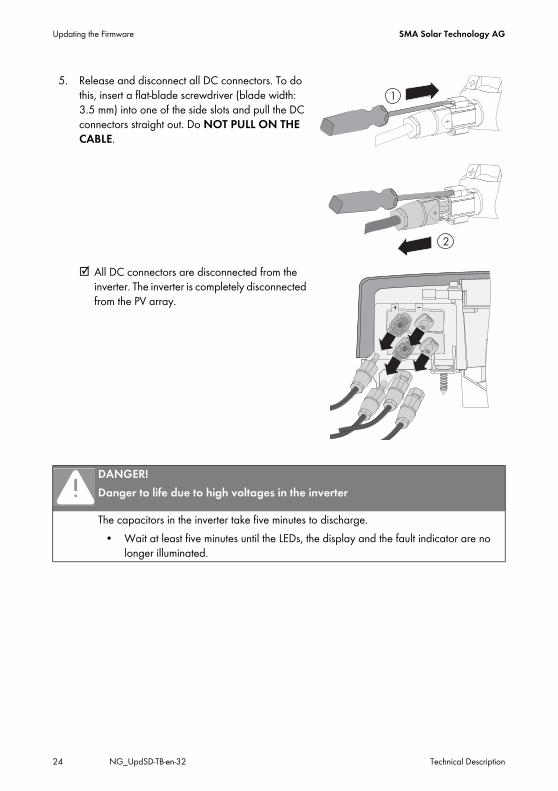
5. Release and disconnect all DC connectors. To do this, insert a flat-blade screwdriver (blade width: 3.5 mm) into one of the side slots and pull the DC connectors straight out. Do NOT PULL ON THE CABLE.
☑ All DC connectors are disconnected from the inverter. The inverter is completely disconnected from the PV array.
DANGER!Danger to life due to high voltages in the inverter
The capacitors in the inverter take five minutes to discharge.• Wait at least five minutes until the LEDs, the display and the fault indicator are no
longer illuminated.

SMA Solar Technology AG Updating the Firmware
Technical Description NG_UpdSD-TB-en-32 25
6. Ensure that no voltage is present at the DC plugs on the inverter.☑ If voltage is present, check the installation.
7. Unlock and remove the AC connector using a screwdriver.
☑ The inverter is now free of voltage. You can now insert the SD card as described in the next step.
Inserting the SD Card8. Open the lower flap of the Quick Module.9. Insert the SD card into the slot with the contacts
facing downward and the slanted corner on the right hand side until it locks into place.
10. Flip the flap down again until it locks into place.11. Leave the SD card inserted for the entire duration of the update.
Updating the Firmware SMA Solar Technology AG
26 NG_UpdSD-TB-en-32 Technical Description
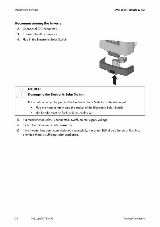
Recommissioning the Inverter12. Connect all DC connectors.13. Connect the AC connector.14. Plug in the Electronic Solar Switch.
15. If a multi-function relay is connected, switch on the supply voltage.16. Switch the miniature circuit-breaker on.☑ If the inverter has been commissioned successfully, the green LED should be on or flashing,
provided there is sufficient solar irradiation.
NOTICE!Damage to the Electronic Solar Switch.
If it is not correctly plugged in, the Electronic Solar Switch can be damaged.• Plug the handle firmly onto the socket of the Electronic Solar Switch. • The handle must be flush with the enclosure.
SMA Solar Technology AG Updating the Firmware
Technical Description NG_UpdSD-TB-en-32 27
4.1.4 STP 8000TL-10/STP 10000TL-10/STP 12000TL-10/STP 15000TL-10/STP 17000TL-10
Disconnecting the Inverter1. Disconnect the miniature circuit-breaker from all three phases and secure against reconnection.2. If a multi-function relay is connected, disconnect its supply voltage and ensure that it cannot be
reconnected.3. Check the status of the Sunny Tripower:
DANGER!Danger to life due to high voltages in the Sunny Tripower Death from electric shockThe Sunny Tripower operates at high voltages and must be disconnected prior to carrying out work on the device. Furthermore, if the DC connectors are pulled out without first unplugging the Electronic Solar Switch, a dangerous electric arc can occur.
• Disconnect the Sunny Tripower as described in the following.
CAUTION!Risk of burns due to hot DC lid
During operation, the small DC lid on the left-hand side of the connection area may get hot.• Do not touch the DC lid when working in the connection area.
NOTICE!Electrostatic discharge can damage the Sunny Tripower
Internal components of the Sunny Tripower can be irreparably damaged by electrostatic discharge.
• Earth yourself before touching any component.
Event MeasureThe Sunny Tripower is beeping or there is an error message on the display prohibiting the removal of the Electronic Solar Switch.
• Wait until the Sunny Tripower stops beeping (after dark) and only then remove the Electronic Solar Switch and the DC connectors.
• Eliminate the fault (see Section 2.2.1 "Beeping inverters of type STP 8000TL-10/STP 10000TL-10/STP 12000TL-10/STP 15000TL-10/STP 17000TL-10" (page 8)).
The Sunny Tripower is not beeping and there is no error message on the display.
• Remove the Electronic Solar Switch.• Proceed to step 4.
Updating the Firmware SMA Solar Technology AG
28 NG_UpdSD-TB-en-32 Technical Description
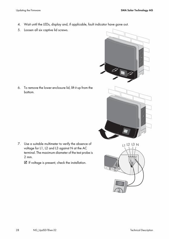
4. Wait until the LEDs, display and, if applicable, fault indicator have gone out.5. Loosen all six captive lid screws.
6. To remove the lower enclosure lid, lift it up from the bottom.
7. Use a suitable multimeter to verify the absence of voltage for L1, L2 and L3 against N at the AC terminal. The maximum diameter of the test probe is 2 mm.☑ If voltage is present, check the installation.
SMA Solar Technology AG Updating the Firmware
Technical Description NG_UpdSD-TB-en-32 29
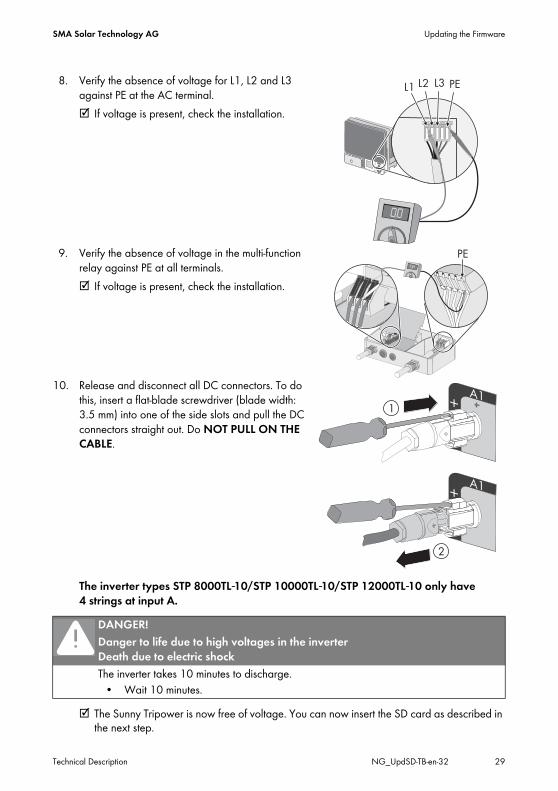
8. Verify the absence of voltage for L1, L2 and L3 against PE at the AC terminal.☑ If voltage is present, check the installation.
9. Verify the absence of voltage in the multi-function relay against PE at all terminals.☑ If voltage is present, check the installation.
10. Release and disconnect all DC connectors. To do this, insert a flat-blade screwdriver (blade width: 3.5 mm) into one of the side slots and pull the DC connectors straight out. Do NOT PULL ON THE CABLE.
The inverter types STP 8000TL-10/STP 10000TL-10/STP 12000TL-10 only have 4 strings at input A.
☑ The Sunny Tripower is now free of voltage. You can now insert the SD card as described in the next step.
DANGER!Danger to life due to high voltages in the inverter Death due to electric shockThe inverter takes 10 minutes to discharge.
• Wait 10 minutes.

Updating the Firmware SMA Solar Technology AG
30 NG_UpdSD-TB-en-32 Technical Description
Inserting the SD Card11. Release the display screw and raise the display slightly.12. Insert the SD card into the slot with the slanted
corner facing downward until it locks into place.
13. Flip down the display and tighten with screws.Commissioning the Inverter14. Check that the AC grid cable is connected correctly.15. Connect all DC connectors.16. Close unused DC inputs with the appropriate DC connectors and sealing plugs.17. Close all enclosure openings.18. Dock the lower enclosure lid at an angle and
attach. The captive screws must protrude.
19. Tighten the screws with 2 Nm torque in the order shown on the right.
SMA Solar Technology AG Updating the Firmware
Technical Description NG_UpdSD-TB-en-32 31
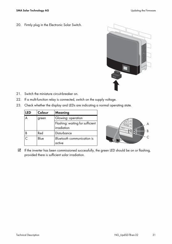
20. Firmly plug in the Electronic Solar Switch.
21. Switch the miniature circuit-breaker on.22. If a multi-function relay is connected, switch on the supply voltage.23. Check whether the display and LEDs are indicating a normal operating state.
☑ If the inverter has been commissioned successfully, the green LED should be on or flashing, provided there is sufficient solar irradiation.
LED Colour MeaningA green Glowing: operation
Flashing: waiting for sufficient irradiation
B Red DisturbanceC Blue Bluetooth communication is
active
Updating the Firmware SMA Solar Technology AG
32 NG_UpdSD-TB-en-32 Technical Description
4.1.5 STP 15000TLHE-10/STP 15000TLEE-10/STP 20000TLHE-10/STP 20000TLEE-10
Disconnecting the Inverter1. Disconnect the miniature circuit-breaker from all three line conductors and secure against
reconnection.2. If a multi-function relay is connected, disconnect its supply voltage and ensure that it cannot be
reconnected.3. If an integrated or external DC switch-disconnector is connected, switch it off.4. Wait until the LEDs, display and fault indicator have gone out.
DANGER!Danger to life due to high voltages in the inverter Death from electric shockThe inverter operates at high voltages and must be disconnected prior to carrying out any work on the device. In addition, if the DC connectors are pulled out without first switching off the DC switch-disconnector, a dangerous electric arc can occur.
• Disconnect the inverter as described in this section.
CAUTION!Risk of burns due to hot DC lid
During operation, the DC lid on the left-hand side of the connection area can get hot.• Take care not to touch the DC lid when working in the connection area.
NOTICE!Electrostatic discharge can damage the inverter
Internal components of the inverter can be irreparably damaged by electrostatic discharge.
• Earth yourself before touching any components.
SMA Solar Technology AG Updating the Firmware
Technical Description NG_UpdSD-TB-en-32 33
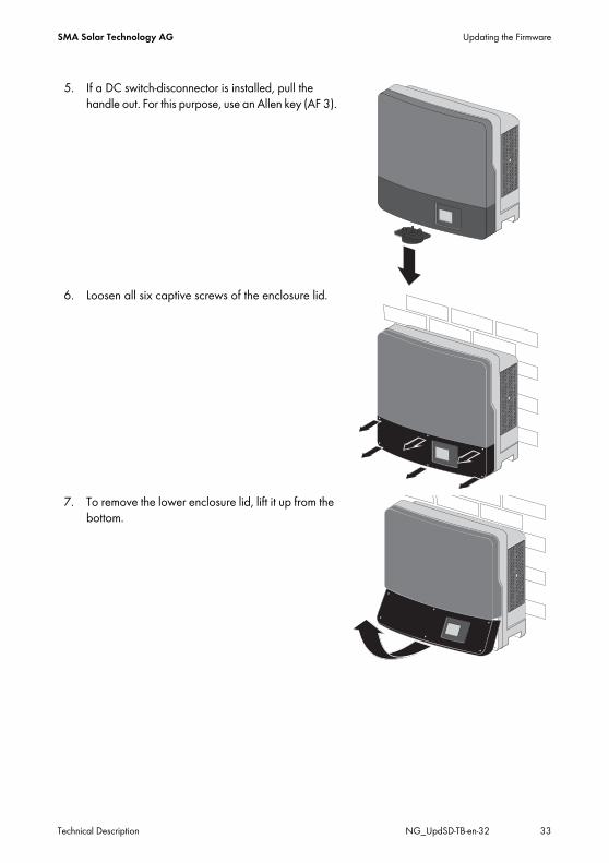
5. If a DC switch-disconnector is installed, pull the handle out. For this purpose, use an Allen key (AF 3).
6. Loosen all six captive screws of the enclosure lid.
7. To remove the lower enclosure lid, lift it up from the bottom.
Updating the Firmware SMA Solar Technology AG
34 NG_UpdSD-TB-en-32 Technical Description
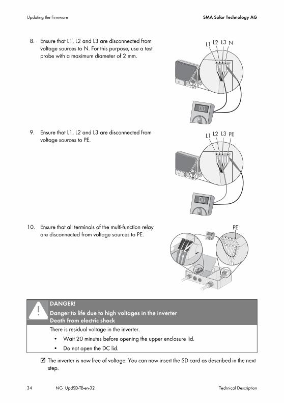
8. Ensure that L1, L2 and L3 are disconnected from voltage sources to N. For this purpose, use a test probe with a maximum diameter of 2 mm.
9. Ensure that L1, L2 and L3 are disconnected from voltage sources to PE.
10. Ensure that all terminals of the multi-function relay are disconnected from voltage sources to PE.
☑ The inverter is now free of voltage. You can now insert the SD card as described in the next step.
DANGER!Danger to life due to high voltages in the inverter Death from electric shockThere is residual voltage in the inverter.
• Wait 20 minutes before opening the upper enclosure lid.• Do not open the DC lid.
SMA Solar Technology AG Updating the Firmware
Technical Description NG_UpdSD-TB-en-32 35
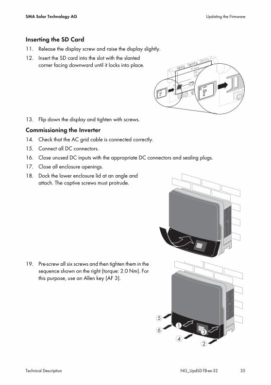
Inserting the SD Card11. Release the display screw and raise the display slightly.12. Insert the SD card into the slot with the slanted
corner facing downward until it locks into place.
13. Flip down the display and tighten with screws.Commissioning the Inverter14. Check that the AC grid cable is connected correctly.15. Connect all DC connectors.16. Close unused DC inputs with the appropriate DC connectors and sealing plugs.17. Close all enclosure openings.18. Dock the lower enclosure lid at an angle and
attach. The captive screws must protrude.
19. Pre-screw all six screws and then tighten them in the sequence shown on the right (torque: 2.0 Nm). For this purpose, use an Allen key (AF 3).
Updating the Firmware SMA Solar Technology AG
36 NG_UpdSD-TB-en-32 Technical Description
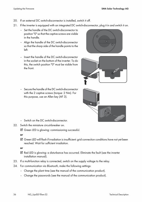
20. If an external DC switch-disconnector is installed, switch it off.21. If the inverter is equipped with an integrated DC switch-disconnector, plug it in and switch it on.
– Set the handle of the DC switch-disconnector to position "0" so that the captive screws are visible in the handle.
– Align the handle of the DC switch-disconnector so that the sharp side of the handle points to the left.
– Insert the handle of the DC switch-disconnector in the socket on the bottom of the inverter. To do this, the switch position "0" must be visible from the front.
– Secure the handle of the DC switch-disconnector with the 2 captive screws (torque: 2 Nm). For this purpose, use an Allen key (AF 3).
– Switch on the DC switch-disconnector.22. Switch the miniature circuit-breaker on.
☑ Green LED is glowing: commissioning successful.or☑ Green LED will flash if irradiation is insufficient: grid connection conditions have not yet been
reached. Wait for sufficient irradiation.or☑ Red LED is glowing: a disturbance has occurred. Eliminate the fault (see the inverter
installation manual).23. If a multi-function relay is connected, switch on the supply voltage to the relay.24. For communication via Bluetooth, make the following settings:
– Change the plant time (see the manual of the communication product).– Change the passwords (see the manual of the communication product).
SMA Solar Technology AG Updating the Firmware
Technical Description NG_UpdSD-TB-en-32 37
4.2 Update Messages
• < SD card is read >: The inverter starts checking the SD card.
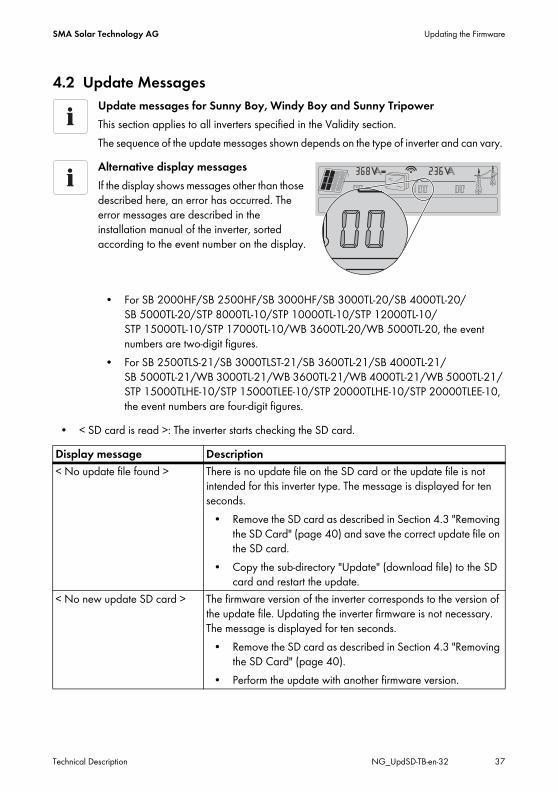
Update messages for Sunny Boy, Windy Boy and Sunny TripowerThis section applies to all inverters specified in the Validity section.The sequence of the update messages shown depends on the type of inverter and can vary.Alternative display messagesIf the display shows messages other than those described here, an error has occurred. The error messages are described in the installation manual of the inverter, sorted according to the event number on the display.
• For SB 2000HF/SB 2500HF/SB 3000HF/SB 3000TL-20/SB 4000TL-20/SB 5000TL-20/STP 8000TL-10/STP 10000TL-10/STP 12000TL-10/STP 15000TL-10/STP 17000TL-10/WB 3600TL-20/WB 5000TL-20, the event numbers are two-digit figures.
• For SB 2500TLS-21/SB 3000TLST-21/SB 3600TL-21/SB 4000TL-21/SB 5000TL-21/WB 3000TL-21/WB 3600TL-21/WB 4000TL-21/WB 5000TL-21/STP 15000TLHE-10/STP 15000TLEE-10/STP 20000TLHE-10/STP 20000TLEE-10, the event numbers are four-digit figures.
Display message Description< No update file found > There is no update file on the SD card or the update file is not
intended for this inverter type. The message is displayed for ten seconds.
• Remove the SD card as described in Section 4.3 "Removing the SD Card" (page 40) and save the correct update file on the SD card.
• Copy the sub-directory "Update" (download file) to the SD card and restart the update.
< No new update SD card > The firmware version of the inverter corresponds to the version of the update file. Updating the inverter firmware is not necessary. The message is displayed for ten seconds.
• Remove the SD card as described in Section 4.3 "Removing the SD Card" (page 40).
• Perform the update with another firmware version.
Updating the Firmware SMA Solar Technology AG
38 NG_UpdSD-TB-en-32 Technical Description
Display Messages during Update• < Update communication >: The communication component is being updated.• < Upd. language table >: The language table is being updated.• < Update main CPU >: The main CPU is being updated.• < Update Display >: The display is being updated.
• < Update RS485I module >: The RS485i module is being updated.• < Update Bluetooth >: The module for Bluetooth® Wireless Technology is being updated.• < Update string prot. >: Only for STP 8000TL-10/STP 10000TL-10/STP 12000TL-10/
STP 15000TL-10/STP 17000TL-10. The electronic string fuse is being updated. ☑ < Update completed >: The firmware update is completed. The message is displayed for
30 seconds. Afterwards, the inverter displays its initialisation messages.Remove the SD card as described in Section 4.3 "Removing the SD Card" (page 40).
< Update file OK > The inverter has compared the update file with the firmware of the inverter and has determined that an update is necessary. The message is displayed for ten seconds.
• Do not remove the SD card during the update process.• The following shows the messages of the inverter
components for which an update can be carried out.The firmware update of all components will take approx. ten minutes.
Display switches offDuring the update, the display may switch off for up to one minute (no display).
SB 4000TL-20/SB 5000TL-20If the first update with firmware version 1.71 is complete, you can start the update with the higher firmware version.
Display message Description
SMA Solar Technology AG Updating the Firmware
Technical Description NG_UpdSD-TB-en-32 39
Faulty update of a component< Update BT failed >: This display message appears for 20 seconds, if the update of a component cannot be carried out after several attempts (e.g. if the Bluetooth update failed). The message for the update of the next component or the message < Update completed > appears in the display.
Watch the display messages for the entire duration of the updateThe message that the update of a certain component has not been carried out is no longer displayed at the end of the entire update sequence. Upon completion of the update sequence, you can no longer see which updates have not been successful.For this reason, SMA Solar Technology AG recommends that you watch the display for the entire duration of the update so that you can see which updates of individual components have not been carried out.If an error message appears, perform the update again. If the error message continues to appear, contact the SMA Service Line (see Section 6 "Contact" (page 43)).
Updating the Firmware SMA Solar Technology AG
40 NG_UpdSD-TB-en-32 Technical Description
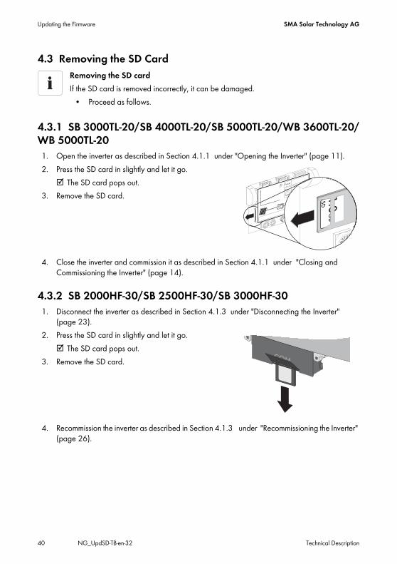
4.3 Removing the SD Card
4.3.1 SB 3000TL-20/SB 4000TL-20/SB 5000TL-20/WB 3600TL-20/WB 5000TL-201. Open the inverter as described in Section 4.1.1 under "Opening the Inverter" (page 11).2. Press the SD card in slightly and let it go.
☑ The SD card pops out.3. Remove the SD card.
4. Close the inverter and commission it as described in Section 4.1.1 under "Closing and Commissioning the Inverter" (page 14).
4.3.2 SB 2000HF-30/SB 2500HF-30/SB 3000HF-301. Disconnect the inverter as described in Section 4.1.3 under "Disconnecting the Inverter"
(page 23).2. Press the SD card in slightly and let it go.
☑ The SD card pops out.3. Remove the SD card.
4. Recommission the inverter as described in Section 4.1.3 under "Recommissioning the Inverter" (page 26).
Removing the SD cardIf the SD card is removed incorrectly, it can be damaged.
• Proceed as follows.
SMA Solar Technology AG Updating the Firmware
Technical Description NG_UpdSD-TB-en-32 41
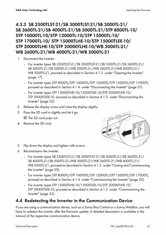
4.3.3 SB 2500TLST-21/SB 3000TLST-21/SB 3000TL-21/SB 3600TL-21/SB 4000TL-21/SB 5000TL-21/STP 8000TL-10/STP 10000TL-10/STP 12000TL-10/STP 15000TL-10/STP 17000TL-10/ STP 15000TLHE-10/STP 15000TLEE-10/STP 20000TLHE-10/STP 20000TLHE-10/WB 3000TL-21/WB 3600TL-21/WB 4000TL-21/WB 5000TL-211. Disconnect the inverter:
– For inverter types SB 2500TLST-21/SB 3000TLST-21/SB 3000TL-21/SB 3600TL-21/SB 4000TL-21/SB 5000TL-21/WB 3000TL-21/WB 3600TL-21/WB 4000TL-21/WB 5000TL-21, proceed as described in Section 4.1.2 under "Opening the Inverter" (page 17).
– For inverter types STP 8000TL/STP 10000TL/STP 12000TL/STP 15000TL/STP 17000TL, proceed as described in Section 4.1.4 under "Disconnecting the Inverter" (page 27).
– For inverter types STP 15000TLHE-10/15000TLEE-10/STP 20000TLHE-10/STP 20000TLEE-10, proceed as described in Section 4.1.5 under "Disconnecting the Inverter" (page 32).
2. Release the display screw and raise the display slightly.3. Press the SD card in slightly and let it go.
☑ The SD card pops out.4. Remove the SD card.
5. Flip down the display and tighten with screws.6. Recommission the inverter.
– For inverter types SB 2500TLST-21/SB 3000TLST-21/SB 3000TL-21/SB 3600TL-21/SB 4000TL-21/SB 5000TL-21/WB 3000TL-21/WB 3600TL-21/WB 4000TL-21/WB 5000TL-21, proceed as described in Section 4.1.2 under "Closing and Commissioning the Inverter" (page 20).
– For inverter types STP 8000TL/STP 10000TL/STP 12000TL/STP 15000TL/STP 17000TL, proceed as described in Section 4.1.4 under "Commissioning the Inverter" (page 30).
– For inverter types STP 15000TLHE-10/15000TLEE-10/STP 20000TLHE-10/STP 20000TLEE-10, proceed as described in Section 4.1.5 under "Commissioning the Inverter" (page 35).
4.4 Redetecting the Inverter in the Communication DeviceIf you are using a communication device, such as a Sunny Boy Control or a Sunny WebBox, you will have to redetect the inverter after the firmware update. A detailed description is available in the manual of the respective communication device.

Checking the Current Firmware Status SMA Solar Technology AG
42 NG_UpdSD-TB-en-32 Technical Description
5 Checking the Current Firmware StatusYou can read the current firmware status of your inverter in the display by tapping the inverter twice or immediately after it has been (re)commissioned.You can also check the firmware version using a communication device or a PC with corresponding software (e.g. Sunny Data Control or Sunny Explorer).
SMA Solar Technology AG Contact
Technical Description NG_UpdSD-TB-en-32 43
6 ContactIf you have technical problems concerning our products, please contact the SMA Service Line. We will need the following data in order to provide you with the necessary assistance:
• Inverter device type• Inverter serial number• Firmware version of the inverter• Special country-specific settings of the inverter (if applicable)• Type and number of the PV modules connected• Installation location and installation altitude of the inverter• Three-digit or four-digit event number and display message of the inverter• LED signal and display message of the inverter• Optional equipment, e.g. communication products• Type of use of the multi-function relay/fault indicator relay (if present)
SMA Solar Technology AG Sonnenallee 134266 Niestetal, Germanywww.SMA.de
SMA Service Line Inverters: +49 561 9522 1499Communication: +49 561 9522 2499Fax: +49 561 9522 4699E‑Mail: [email protected]

SMA Solar Technology AG Legal Provisions
Technical Description NG_UpdSD-TB-en-32 45
Legal ProvisionsThe information contained in this document is the property of SMA Solar Technology AG. Publishing its content, either partially or in full, requires the written permission of SMA Solar Technology AG. Any internal company copying of the document for the purposes of evaluating the product or its correct implementation is allowed and does not require permission.
SMA Factory WarrantyThe current warranty conditions come enclosed with your device. These are also available online at www.SMA-Solar.com and can be downloaded and are available on paper from the usual sales channels if required.
TrademarksAll trademarks are recognized even if these are not marked separately. Missing designations do not mean that a product or brand is not a registered trademark.The Bluetooth® word mark and logos are registered trademarks owned by Bluetooth SIG, Inc. and any use of such marks by SMA Solar Technology AG is under licence.QR Code® is a registered trademark of DENSO WAVE INCORPORATED.
SMA Solar Technology AGSonnenallee 134266 NiestetalGermanyTel. +49 561 9522-0Fax +49 561 9522-100www.SMA.deE-Mail: [email protected]© 2004 to 2012 SMA Solar Technology AG. All rights reserved