summit x150 series switches
TRANSCRIPT
Extre3585Sant(888(408http:
Summit® Family Switches Hardware Installation Guide
Summit X150 Series
Summit X250e Series
Summit X350 Series
Summit X450 Series
Summit X450a Series
Summit X450e Series
Summit X480 Series
Summit X650 Series
me Networks, Inc. Monroe Street
a Clara, California 95051) 257-3000) 579-2800//www.extremenetworks.com
Published: March 2010Part Number: 100286-00 Rev. 08

2
AccessAdapt, Alpine, Altitude, BlackDiamond, EPICenter, ExtremeWorks Essentials, Ethernet Everywhere, Extreme Enabled, Extreme Ethernet Everywhere, Extreme Networks, Extreme Standby Router Protocol, Extreme Turbodrive, Extreme Velocity, ExtremeWare, ExtremeWorks, ExtremeXOS, Go Purple Extreme Solution, ExtremeXOS ScreenPlay, ReachNXT, Sentriant, ServiceWatch, Summit, SummitStack, Triumph, Unified Access Architecture, Unified Access RF Manager, UniStack, the Extreme Networks logo, the Alpine logo, the BlackDiamond logo, the Extreme Turbodrive logo, the Summit logos, and the Powered by ExtremeXOS logo are trademarks or registered trademarks of Extreme Networks, Inc. or its subsidiaries in the United States and/or other countries.
sFlow is a registered trademark of InMon Corporation.
Specifications are subject to change without notice.
All other registered trademarks, trademarks, and service marks are property of their respective owners.
© 2007 – 2010 Extreme Networks, Inc. All Rights Reserved.
For safety compliance information, see Appendix A, “Safety Information.”
Summit Family Switches Hardware Installation Guide

Summit
Contents
Preface........................................................................................................................................... 9
Conventions................................................................................................................................9Related Publications .................................................................................................................10
Part 1: About the Summit Family Switches
Chapter 1: Summit Family Switches................................................................................................ 13
Overview of the Summit Switches ...............................................................................................13Combination Ports and Failover ............................................................................................16
Summit X150 Series Switches ...................................................................................................17Summit X150-24t Switch ....................................................................................................18Summit X150-24p Switch ...................................................................................................19Summit X150-48t Switch ....................................................................................................20Summit X150 Series Switch LEDs ........................................................................................21
Summit X250e Series Switches..................................................................................................22Summit X250e-24t Switch ..................................................................................................23Summit X250e-24tDC Switch ..............................................................................................24Summit X250e-24p Switch..................................................................................................25Summit X250e-24x Switch ..................................................................................................27Summit X250e-24xDC Switch ..............................................................................................28Summit X250e-48t Switch ..................................................................................................30Summit X250e-48tDC Switch ..............................................................................................31Summit X250e-48p Switch..................................................................................................33Summit X250e-48p Power Supplies .....................................................................................34
Internal Power Supply....................................................................................................34External Power Supplies.................................................................................................34
Summit X250e Series Switch LEDs ......................................................................................35Summit X350 Series Switches ...................................................................................................36
Summit X350-24t Switch ....................................................................................................37Summit X350-48t Switch ....................................................................................................38Summit X350 Series Switch LEDs ........................................................................................41
Summit X450, X450a, and X450e Series Switches ......................................................................42Summit X450 Series Switches .............................................................................................43
Summit X450-24t Switch ..............................................................................................43Summit X450-24x Switch..............................................................................................44
Summit X450a Series Switches............................................................................................46Summit X450a-24t Switch.............................................................................................46Summit X450a-24tDC Switch ........................................................................................48Summit X450a-24x Switch ............................................................................................49Summit X450a-24xDC Switch ........................................................................................51Summit X450a-48t Switch.............................................................................................52Summit X450a-48tDC Switch ........................................................................................53
Summit X450e Series Switches............................................................................................55Summit X450e-24p Switch............................................................................................55Summit X450e-48p Switch............................................................................................57
Family Switches Hardware Installation Guide 29

Contents
30
Summit X450e-48p Power Supplies................................................................................58Internal Power Supply..............................................................................................58External Power Supplies...........................................................................................58
Summit X450, X450a, and X450e Series Switch LEDs...........................................................60Summit X480 Series Switches ...................................................................................................62
Summit X480-24x Switch....................................................................................................63Summit X480-48x Switch....................................................................................................64Summit X480-48t Switch ....................................................................................................65VIM2-SummitStack Versatile Interface Module.......................................................................66VIM2-10G4X Versatile Interface Module................................................................................66VIM2-SummitStack128 Versatile Interface Module ................................................................67Summit X480 Series Switch LEDs ........................................................................................68
Summit X650 Series Switches ...................................................................................................69Summit X650-24t Switch ....................................................................................................70Summit X650-24x Switch....................................................................................................71VIM1-SummitStack Versatile Interface Module.......................................................................72VIM1-10G8X Versatile Interface Module................................................................................72VIM1-SummitStack512 Versatile Interface Module ................................................................73VIM1-SummitStack256 Versatile Interface Module ................................................................73Summit X650 Series Switch LEDs ........................................................................................74
Chapter 2: Summit Power Supplies................................................................................................. 75
Overview ..................................................................................................................................75EPS-160 External Power Module (with EPS-T) .............................................................................76EPS-LD External Power Supply Unit............................................................................................77EPS-500 External Power Supply Unit..........................................................................................78EPS-150DC External Power Module (with EPS-T2).......................................................................78EPS-600LS External Power Module ............................................................................................79
PoE Redundant Power Configurations....................................................................................79Single 600-LS Module Configuration: Redundant PoE Power.............................................79Dual 600-LS Module Configuration: Full Power ................................................................80Triple 600-LS Module Configuration: Full Redundant Power..............................................80Internal-to-External PSU Transfer ...................................................................................80
Internal PSU Failure with Single EPS-600LS Module .................................................80Two or Three EPS-600LS Modules ............................................................................80
External-to-Internal PSU Transfer ...................................................................................80Active Internal PSU with Single 600-LS Module Failure..............................................80Inactive Internal PSU with a Dual EPS-600LS Configuration and Module Failure...........80Disconnecting the EPS-C/EPS-600LS........................................................................81
Summit X480 Power Supplies ....................................................................................................81Summit X650 Power Supplies ....................................................................................................82
Part 2: Installing the Hardware
Chapter 3: Site Preparation............................................................................................................ 85
Planning Your Site ....................................................................................................................85Meeting Site Requirements ........................................................................................................86
Operating Environment Requirements ...................................................................................86Building and Electrical Codes.........................................................................................86Wiring Closet Considerations ..........................................................................................87
Summit Family Switches Hardware Installation Guide

Contents
Temperature .................................................................................................................87Humidity ......................................................................................................................88Spacing Requirements and Airflow..................................................................................88Electrostatic Discharge ..................................................................................................88
Rack Specifications and Recommendations ...........................................................................88Mechanical Recommendations for the Rack.....................................................................89Protective Grounding for the Rack...................................................................................89Space Requirements for the Rack ...................................................................................89Securing the Rack .........................................................................................................90
Evaluating and Meeting Cable Requirements ...............................................................................90Cabling Standards ...............................................................................................................90Cable Labeling and Record Keeping......................................................................................91Installing Cable...................................................................................................................91
Fiber Optic Cable ..........................................................................................................92Cable Distances ............................................................................................................93
RJ-45 Connector Jackets .....................................................................................................94Radio Frequency Interference...............................................................................................94
Meeting Power Requirements .....................................................................................................95PoE Devices .......................................................................................................................95Power Supply Requirements.................................................................................................95AC Power Cables .................................................................................................................95Uninterruptible Power Supply Requirements ..........................................................................96
Selecting a UPS............................................................................................................96Calculating Volt-Amperage Requirements.........................................................................96UPS Transition Time .....................................................................................................97
DC Power Requirements ......................................................................................................97Applicable Industry Standards....................................................................................................97
Chapter 4: Building a SummitStack Configuration ........................................................................... 99
Stacking Summit Family Switches ..............................................................................................99Slot Numbers ...................................................................................................................100About Redundancy ............................................................................................................100
Stacking Cables ......................................................................................................................101Placing Summit Family Switches for Stacked Operation..............................................................102Connecting the Switches to Form the Stack Ring .......................................................................103
Using SummitStack Ports and 40G Stacking Cables .............................................................103Single-Rack Stacking Configurations .............................................................................103Multiple-Rack Stacking Configurations ..........................................................................106
Combining Different Types of Stacking Ports........................................................................107Using the VIM1-SummitStack512 Module...........................................................................109
Connecting Stacking Cables .....................................................................................................110Connecting a SummitStack 40G Cable to a Stacking Port .....................................................110Connecting a SummitStack 128G Cable ..............................................................................111Connecting a SummitStack 128G/20G Stacking Cable .........................................................113Connecting a SummitStack 128G/64G Stacking Cable .........................................................115Connecting a SummitStack 64G Stacking Cable ..................................................................117Connecting a SummitStack 64G/20G Stacking Cable ...........................................................119
Connecting Console Ports for a Stack ........................................................................................120Management Port Cabling ........................................................................................................120Stacking Port LEDs .................................................................................................................120
Summit Family Switches Hardware Installation Guide 31
Contents
32
Chapter 5: Installing Summit Family Switches............................................................................... 121
Safety Information ..................................................................................................................121Installing a Summit Family Switch (Models Other than Summit X480 and X650 Series) ................122
Rack-Mounting a Summit Switch (Models Other than Summit X480 and X650 Series) ............122Free-Standing and Desktop Mounting of Multiple Switches ...................................................124Removing an AC-Powered Summit Switch from a Rack (Models Other than Summit X650 Series)...124Installing and Removing Summit DC-Powered Switches ........................................................124
Connecting the Internal DC Power Supply to the DC Source Voltage .................................125Grounding a Summit DC-Powered Switch.......................................................................125Connecting the DC Wiring Harness to the DC Source Voltage ...........................................127Attaching the DC Wiring Harness to the DC Power Socket on the Switch...........................128
Removing a Summit DC-Powered Switch from a Rack...........................................................128Installing a Summit X480 Series Switch....................................................................................129
Pre-installation Requirements.............................................................................................129Selecting Rear Mounting Brackets ......................................................................................130Mid-Mounting the Switch in a Two-Post Rack ......................................................................130Front-Mounting the Switch in a Two-Post Rack ....................................................................133Installing the Switch in a Four-Post Rack ............................................................................134
Installing Summit X480 Power Supplies....................................................................................136AC Power Supply Cords......................................................................................................136Installing a Summit X480 AC PSU......................................................................................137Installing a Summit X480 DC Power Supply ........................................................................138
Required Tools and Materials .......................................................................................139Preparing the Cables ...................................................................................................139Installing the Power Supply ..........................................................................................140Connecting the Ground Wire.........................................................................................141Connecting the PSU to the DC Source Voltage................................................................143
Removing a Summit X480 Series Switch...................................................................................145Removing the Power Supplies.............................................................................................145
Removing a Summit X480 AC Power Supply ..................................................................146Removing a Summit X480 DC Power Supply..................................................................146
Removing a Mid-Mounted Switch from a Two-Post Rack .......................................................147Removing a Front-Mounted Switch from a Two-Post Rack .....................................................149Removing a Switch from a Four-Post Rack...........................................................................150
Installing a Summit X650 Series Switch....................................................................................151Pre-installation Requirements.............................................................................................152Selecting Rear Mounting Brackets ......................................................................................152Installing the Switch in a Two-Post Rack .............................................................................152Installing the Switch in a Cabinet or Four-Post Rack.............................................................156
Installing Summit X650 Power Supplies....................................................................................158AC Power Supply Cords......................................................................................................158Installing a Summit X650 AC Power Supply.........................................................................159Installing a Summit X650 DC Power Supply ........................................................................160
Required Tools and Materials .......................................................................................161Preparing the Cables ...................................................................................................161Installing the Power Supply ..........................................................................................162Connecting the Ground Cable .......................................................................................163Connecting the PSU to the DC Source Voltage................................................................164
Removing a Summit X650 Series Switch...................................................................................166Removing the Power Supplies.............................................................................................166
Summit Family Switches Hardware Installation Guide
Contents
Removing a Summit X650 AC Power Supply’ .................................................................167Removing a DC Power Supply .......................................................................................167
Removing a Summit X650 Series Switch from a Two-Post Rack.............................................168Removing a Summit X650 Series Switch from a Cabinet or Four-Post Rack ............................170
Connecting Network Interface Cables ........................................................................................171Initial Management Access ......................................................................................................172
Connecting Equipment to the Console Port ..........................................................................172Logging In for the First Time ..............................................................................................173
Chapter 6: Installing Summit External Power Supplies................................................................... 175
Safety ....................................................................................................................................175Pre-installation Requirements ..................................................................................................176Installing an EPS-160 External Power Module (with EPS-T) ........................................................176
Rack-Mounting the EPS-T ..................................................................................................176Installing an EPS-160 Power Supply into an EPS-T ..............................................................177Connecting the EPS-160 Power Supply to the Switch ...........................................................177Removing an EPS-160 Power Supply from an EPS-T ............................................................179
Installing an EPS-LD External Power Supply ..............................................................................179Rack-mounting the EPS-LD Power Supply ...........................................................................179Connecting the EPS-LD to the Switch .................................................................................180Connecting the EPS-LD to Power ........................................................................................181Removing an EPS-LD ........................................................................................................182
Installing an EPS-500 External Power Supply Unit .....................................................................182Rack-mounting an EPS-500 Power Supply ..........................................................................183Connecting the EPS-500 Power Supply ...............................................................................183Removing an EPS-500 Power Supply ..................................................................................185
Installing an EPS-150DC External Power Module (with EPS-T2) ..................................................185Rack-mounting the EPS-T2................................................................................................186Installing an EPS-150DC Power Supply...............................................................................186
Connecting the DC Wiring Harness to the DC Source Voltage ...........................................187Installing an EPS-150DC Unit into an EPS-T2 ...............................................................188Connecting the DC Wiring Harness to the DC Power Socket on the EPS-150DC.................188Connecting the EPS-150DC to a Switch ........................................................................188
Removing an EPS-150DC Power Module .............................................................................190Installing an EPS-600LS External Power Module .......................................................................190
Installing an EPS-C Chassis ...............................................................................................191Installing an EPS-600LS Power Supply ...............................................................................193Removing an EPS-600LS Power Module..............................................................................195
Chapter 7: Summit Option Cards................................................................................................... 197
Overview ................................................................................................................................197Safety Information ..................................................................................................................198Summit XGM-2xn Option Card..................................................................................................198
Mixing ZR XENPAKs with Other Types.................................................................................199Summit XGM2-2xn Option Card................................................................................................199Summit XGM2-2xf Option Card ................................................................................................200Summit XGM2-2sf Option Card ................................................................................................201Summit XGM2-2bt Option Card................................................................................................201Installing a Summit Port Option Card ........................................................................................202
Summit Family Switches Hardware Installation Guide 33
Contents
34
Chapter 8: Maintenance Procedures for Summit X650 and Summit X480 Series Switches .............. 205
Replacing a Summit X650 AC PSU...........................................................................................205Replacing a Summit X650 DC Power Supply .............................................................................208
Removing the PSU ............................................................................................................208Installing the Replacement PSU .........................................................................................209Connecting the Ground Wire...............................................................................................209Connecting the DC Power Cables ........................................................................................210
Replacing a Summit X480/X650 Fan Module ............................................................................213Replacing a Versatile Interface Module (VIM).............................................................................214
Part 3: Appendices
Appendix A: Safety Information .................................................................................................... 219Considerations Before Installing ...............................................................................................219Installing External Power Supply Units ......................................................................................220Maintenance Safety.................................................................................................................221General Safety Precautions ......................................................................................................221Cable Routing for LAN Systems ................................................................................................221
PoE Devices .....................................................................................................................222Selecting Power Supply Cords ..................................................................................................222Battery Replacement and Disposal............................................................................................223Fiber Optic Ports—Optical Safety .............................................................................................223
SFP (Mini-GBIC), XENPAK, and XFP Regulatory Compliance .................................................224
Appendix B: Technical Specifications .......................................................................................... 231Summit X150 Series Switches .................................................................................................231Summit X250e Series Switches................................................................................................235Summit X350 Series Switches .................................................................................................241Summit X450 Series Switches .................................................................................................244Summit X450a Series Switches................................................................................................246Summit X450e Series Switches................................................................................................250Summit X480 Series Switches .................................................................................................253Summit X480 Power Supplies ..................................................................................................257Summit X650 Series Switches .................................................................................................259Summit X650 Power Supplies ..................................................................................................264Summit External Power Supplies ..............................................................................................265Console Connector Pinouts.......................................................................................................270
Index .......................................................................................................................................... 273
Summit Family Switches Hardware Installation Guide

Summit
Preface
This guide provides the instructions and supporting information needed to install the following Extreme Networks® Summit® switches:
● Summit X150 series switches
● Summit X250e series switches
● Summit X350 series switches
● Summit X450 series switches
● Summit X450a series switches
● Summit X450e series switches
● Summit X480 series switches
● Summit X650 series switches
The guide includes information about site preparation, switch functionality, and switch operation.
NOTE
The Summit X150 series switches, Summit X250e series switches, Summit X350 series switches, Summit X450 series switches, Summit X450e series switches, and Summit X450a series switches are called the Summit family switches when referred to collectively.
This guide is intended for use by network administrators responsible for installing and setting up network equipment. It assumes a basic working knowledge of:
● Local area networks (LANs)
● Ethernet concepts
● Ethernet switching and bridging concepts
● Routing concepts
● Simple Network Management Protocol (SNMP)
● Basic equipment installation procedures
See the ExtremeXOS Concepts Guide and the ExtremeXOS Command Reference Guide for information about configuring Extreme Networks Summit family switches.
NOTE
If the information in the installation note or release note shipped with your Extreme Networks switch differs from the information in this guide, follow the installation or release note.
ConventionsTable 1 and Table 2 list conventions used throughout this guide.
Family Switches Hardware Installation Guide 35

Preface
36
Related PublicationsThe Extreme Networks ExtremeXOS® switch documentation set includes:
● ExtremeXOS Concepts Guide
● ExtremeXOS Command Reference Guide
● ExtremeXOS Release Notes
● BlackDiamond® 20800 Series Switches Hardware Installation Guide
● BlackDiamond 10808 Switch Hardware Installation Guide
● BlackDiamond 12800 Series Switches Hardware Installation Guide
● BlackDiamond 8800 Series Switches Hardware Installation Guide
● Extreme Networks Pluggable Interface Modules Installation Guide
Documentation for Extreme Networks products is available from the Extreme Networks website at the following location:
http://www.extremenetworks.com/go/documentation
You can select and download the following Extreme Networks documentation from the Documentation Overview page:
● Software User Guides
● Hardware Installation Guides
You can find archived user guides for software at:
http://www.extremenetworks.com/services/documentation/swuserguides.asp
You can also find archived installation guides for hardware at:
http://www.extremenetworks.com/services/documentation/hwuserguides.asp
Table 1: Notice Icons
Icon Notice Type Alerts you to...
Note Important features or instructions.
Caution Risk of personal injury, system damage, or loss of data.
Warning Risk of severe personal injury.
Table 2: Text Conventions
Convention Description
Screen displays This typeface represents information as it appears on the screen, or command syntax.
Words in italicized type Italics emphasize a point of information or denote new terms at the place where they are defined in the text. Book titles are printed in italics.
Summit Family Switches Hardware Installation Guide
1 About the Summit Family Switches

1 Summit Family Switches
This chapter describes the Summit family switches and includes the following sections:
● Overview of the Summit Switches on page 39
● Summit X150 Series Switches on page 43
● Summit X250e Series Switches on page 48
● Summit X350 Series Switches on page 62
● Summit X450, X450a, and X450e Series Switches on page 68
● Summit X480 Series Switches on page 88
● Summit X650 Series Switches on page 95
Overview of the Summit SwitchesThe Summit family switches are compact enclosures 1.75 inches high (1 U). They provide 24 or 48 high-density copper or fiber optic ports operating at speeds up to 10 Gbps, with combination copper/fiber uplink ports. PoE connections and options for adding 10-Gbps or 100 Gbps uplink connections are available on some models. Many Summit switches include high-speed stacking interfaces that allow you to connect up to eight Summit switches into a single SummitStack™
management entity. Summit models are available for AC or DC power connection; all Summit switches make provision for redundant power supplies. Most models have connections for optional external redundant power supplies; the Summit X480 series and X650 series switches provide two bays for pluggable power supplies.
Most Summit models are available in versions that are compliant with the Trade Agreements Act (TAA); these versions are identified by a -TAA suffix on the model number. Functionally, the TAA-compliant models are completely equivalent to the matching versions that are not TAA-compliant. In all feature descriptions, references to a specific Summit switch model also apply to the equivalent TAA-compliant model.
Table 3 and Table 4 on page 40 and Table 5 on page 41 list the Summit switch series and summarize the features available in each series.
Summit Family Switches Hardware Installation Guide 39
Summit Family Switches
40
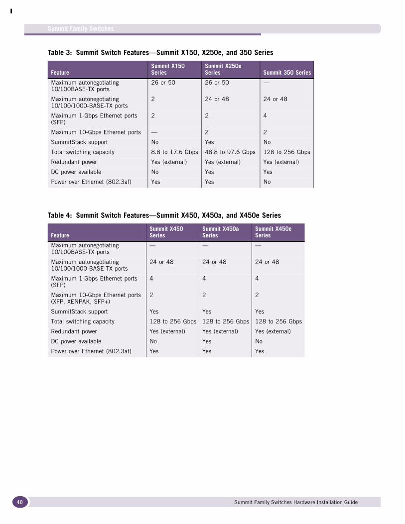
Table 3: Summit Switch Features—Summit X150, X250e, and 350 Series
FeatureSummit X150 Series
Summit X250e Series Summit 350 Series
Maximum autonegotiating 10/100BASE-TX ports
26 or 50 26 or 50 —
Maximum autonegotiating 10/100/1000-BASE-TX ports
2 24 or 48 24 or 48
Maximum 1-Gbps Ethernet ports (SFP)
2 2 4
Maximum 10-Gbps Ethernet ports — 2 2
SummitStack support No Yes No
Total switching capacity 8.8 to 17.6 Gbps 48.8 to 97.6 Gbps 128 to 256 Gbps
Redundant power Yes (external) Yes (external) Yes (external)
DC power available No Yes Yes
Power over Ethernet (802.3af) Yes Yes No
Table 4: Summit Switch Features—Summit X450, X450a, and X450e Series
FeatureSummit X450 Series
Summit X450a Series
Summit X450e Series
Maximum autonegotiating 10/100BASE-TX ports
— — —
Maximum autonegotiating 10/100/1000-BASE-TX ports
24 or 48 24 or 48 24 or 48
Maximum 1-Gbps Ethernet ports (SFP)
4 4 4
Maximum 10-Gbps Ethernet ports (XFP, XENPAK, SFP+)
2 2 2
SummitStack support Yes Yes Yes
Total switching capacity 128 to 256 Gbps 128 to 256 Gbps 128 to 256 Gbps
Redundant power Yes (external) Yes (external) Yes (external)
DC power available No Yes No
Power over Ethernet (802.3af) Yes Yes Yes
Summit Family Switches Hardware Installation Guide
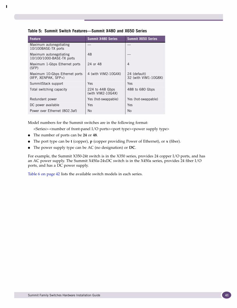
Model numbers for the Summit switches are in the following format:
<Series>-<number of front-panel I/O ports><port type><power supply type>
● The number of ports can be 24 or 48.
● The port type can be t (copper), p (copper providing Power of Ethernet), or x (fiber).
● The power supply type can be AC (no designation) or DC.
For example, the Summit X350-24t switch is in the X350 series, provides 24 copper I/O ports, and has an AC power supply. The Summit X450a-24xDC switch is in the X450a series, provides 24 fiber I/O ports, and has a DC power supply.
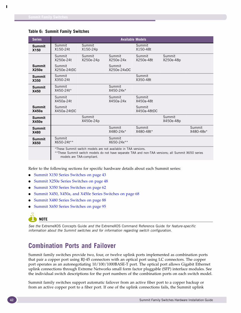
Table 6 on page 42 lists the available switch models in each series.
Table 5: Summit Switch Features—Summit X480 and X650 Series
Feature Summit X480 Series Summit X650 Series
Maximum autonegotiating 10/100BASE-TX ports
— —
Maximum autonegotiating 10/100/1000-BASE-TX ports
48 —
Maximum 1-Gbps Ethernet ports (SFP)
24 or 48 4
Maximum 10-Gbps Ethernet ports (XFP, XENPAK, SFP+)
4 (with VIM2-10G4X) 24 (default)32 (with VIM1-10G8X)
SummitStack support Yes Yes
Total switching capacity 224 to 448 Gbps(with VIM2-10G4X)
488 to 680 Gbps
Redundant power Yes (hot-swappable) Yes (hot-swappable)
DC power available Yes Yes
Power over Ethernet (802.3af) No No
Summit Family Switches Hardware Installation Guide 41
Summit Family Switches
42
Refer to the following sections for specific hardware details about each Summit series:
● Summit X150 Series Switches on page 43
● Summit X250e Series Switches on page 48
● Summit X350 Series Switches on page 62
● Summit X450, X450a, and X450e Series Switches on page 68
● Summit X480 Series Switches on page 88
● Summit X650 Series Switches on page 95
NOTE
See the ExtremeXOS Concepts Guide and the ExtremeXOS Command Reference Guide for feature-specific information about the Summit switches and for information regarding switch configuration.
Combination Ports and FailoverSummit family switches provide two, four, or twelve uplink ports implemented as combination ports that pair a copper port using RJ-45 connectors with an optical port using LC connectors. The copper port operates as an autonegotiating 10/100/1000BASE-T port. The optical port allows Gigabit Ethernet uplink connections through Extreme Networks small form factor pluggable (SFP) interface modules. See the individual switch descriptions for the port numbers of the combination ports on each switch model.
Summit family switches support automatic failover from an active fiber port to a copper backup or from an active copper port to a fiber port. If one of the uplink connections fails, the Summit uplink
Table 6: Summit Family Switches
Series Available Models
Summit X150
Summit X150-24t
Summit X150-24p
Summit X150-48t
Summit X250e
Summit X250e-24t
Summit X250e-24tDC
Summit X250e-24p
Summit X250e-24x
Summit X250e-24xDC
Summit X250e-48t
Summit X250e-48p
Summit X350
Summit X350-24t
Summit X350-48t
Summit X450
Summit X450-24t*
Summit X450-24x*
Summit X450a
Summit X450a-24t
Summit X450a-24tDC
Summit X450a-24x
Summit X450a-48t
Summit X450a-48tDC
Summit X450e
Summit X450e-24p
Summit X450e-48p
Summit X480
Summit X480-24x*
Summit X480-48t*
Summit X480-48x*
Summit X650
Summit X650-24t**
Summit X650-24x**
*These Summit switch models are not available in TAA versions.**These Summit switch models do not have separate TAA and non-TAA versions; all Summit X650 series
models are TAA-compliant.
Summit Family Switches Hardware Installation Guide

connection automatically fails over to the second connection. To set up a redundant link on a combination port, connect the active 1000BASE-T and fiber links to both the RJ-45 and SFP interfaces of that port.
Gigabit Ethernet uplink redundancy on the Summit family switches follows these rules:
● With both the SFP and 1000BASE-T interfaces connected on a combination port, only one interface can be activated. The other is inactive.
● If only one interface is connected, the switch activates the connected interface.
● The switch determines whether the port uses the fiber or copper connection based on the order in which the connectors are inserted into the switch. When the switch senses that an SFP and a copper connector are inserted, the switch enables the uplink redundancy feature. For example, if you first connect copper ports 25 and 26 on a Summit X250e-24t switch, and then insert SFPs into ports 25 and 26, the switch assigns the copper ports as active ports and the fiber ports as redundant ports.
Hardware determines when a link is lost and swaps the primary and redundant ports to maintain stability. After a failover occurs, the switch keeps the current port assignment until another failure occurs or a user changes the assignment using the CLI. For more information about configuring automatic failover on combination ports, see the ExtremeXOS Concepts Guide.
Summit X150 Series SwitchesThe Summit X150 series switches provide 24 or 48 fixed 10/100BASE-T Ethernet ports that deliver high-density copper connectivity for 2.4 Gbps or 4.8 Gbps. Models are available with PoE and without PoE. Each Summit X150 series switch has two combination ports that provide 10/100/1000 BASE-T or SFP connectivity for 2 Gbps of copper or fiber connectivity. A serial console port on the front panel allows you to connect a terminal and perform local management. On the back of the switch, an Ethernet management port can be used to connect the system to a parallel management network for administration. Alternatively, you can use an Ethernet cable to connect this port directly to a laptop to view and locally manage the switch configurations.
The rear panel of the switch provides an AC power input socket and a redundant power connector. The internal power supply operates from 100 VAC to 240 VAC. The switch automatically adjusts to the supply voltage. The redundant power connector allows you to connect the switch to the EPS-160 or EPS-500 external power supply. When a compatible external power supply is used with the Summit X150 series switch, the internal and external power supplies are fully fault tolerant and load-sharing. If one power supply fails, the other power supply will provide sufficient power to operate the switch.
The Summit X150e series switches include the following switches:
● Summit X150-24t Switch
● Summit X150-24t-TAA Switch
● Summit X150-24p Switch
● Summit X150-24p-TAA Switch
● Summit X150-48t Switch
● Summit X150-48t-TAA Switch
NOTE
In the descriptions that follow, references to a Summit X150 series model number also apply to the equivalent TAA-compliant switch version.
Summit Family Switches Hardware Installation Guide 43

Summit Family Switches
44
Summit X150-24t SwitchThe front panel of the Summit X150-24t switch (Figure 1) includes:
● Twenty-four fixed autosensing 10/100BASE-T ports (ports 1–24) that provide 2.4 Gbps of high-density copper connectivity
● Two combination ports (ports 25–26) using RJ-45 connectors and SFPs to provide 2 Gbps of copper or fiber connectivity
For more information about combination ports, see “Combination Ports and Failover” on page 42.
For information about SFPs, see the Extreme Networks Pluggable Interface Modules Installation Guide.
● LEDs to indicate port status and switch operating conditions.
For a description of the LEDs and their operation, see “Summit X150 Series Switch LEDs” on page 47.
● Serial console port used to connect a terminal and perform local management.
Figure 1: Summit X150-24t Switch Front Panel
The rear panel of the Summit X150-24t switch (Figure 2) includes:
● Ethernet management port with associated LEDs
● Redundant power input connector for optional connection to the EPS-160 External Power Module.
See “EPS-160 External Power Module (with EPS-T)” on page 102 for more information. The connecting redundant power supply cable is shipped with the EPS-160 unit.
● AC power input socket
Figure 2: Summit X150-24t Switch Rear Panel
1
2
Stack
SH_050B
10/100 Mbps portsConsole
port
Combination ports
SH_051
Management port
Power socket
External powersupply connection
Summit Family Switches Hardware Installation Guide
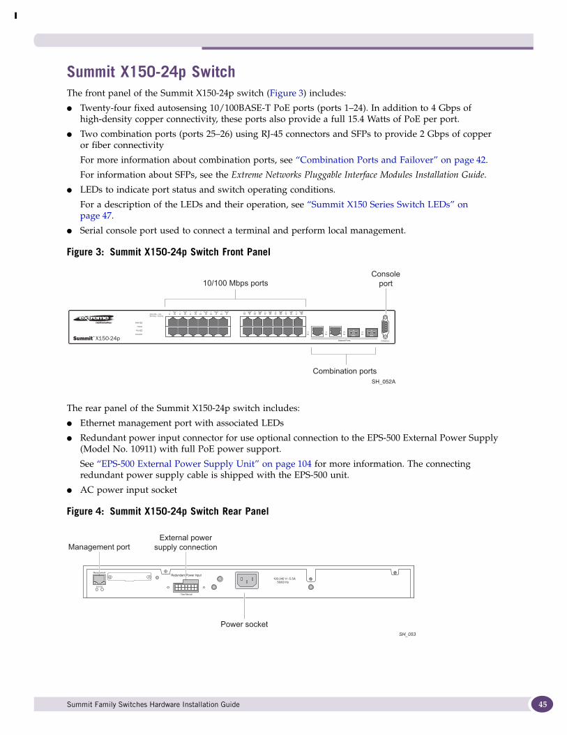
Summit X150-24p SwitchThe front panel of the Summit X150-24p switch (Figure 3) includes:
● Twenty-four fixed autosensing 10/100BASE-T PoE ports (ports 1–24). In addition to 4 Gbps of high-density copper connectivity, these ports also provide a full 15.4 Watts of PoE per port.
● Two combination ports (ports 25–26) using RJ-45 connectors and SFPs to provide 2 Gbps of copper or fiber connectivity
For more information about combination ports, see “Combination Ports and Failover” on page 42.
For information about SFPs, see the Extreme Networks Pluggable Interface Modules Installation Guide.
● LEDs to indicate port status and switch operating conditions.
For a description of the LEDs and their operation, see “Summit X150 Series Switch LEDs” on page 47.
● Serial console port used to connect a terminal and perform local management.
Figure 3: Summit X150-24p Switch Front Panel
The rear panel of the Summit X150-24p switch includes:
● Ethernet management port with associated LEDs
● Redundant power input connector for use optional connection to the EPS-500 External Power Supply (Model No. 10911) with full PoE power support.
See “EPS-500 External Power Supply Unit” on page 104 for more information. The connecting redundant power supply cable is shipped with the EPS-500 unit.
● AC power input socket
Figure 4: Summit X150-24p Switch Rear Panel
SH_052A
10/100 Mbps portsConsole
port
Combination ports
Management port
Power socket
External powersupply connection
SH_053
Summit Family Switches Hardware Installation Guide 45
Summit Family Switches
46
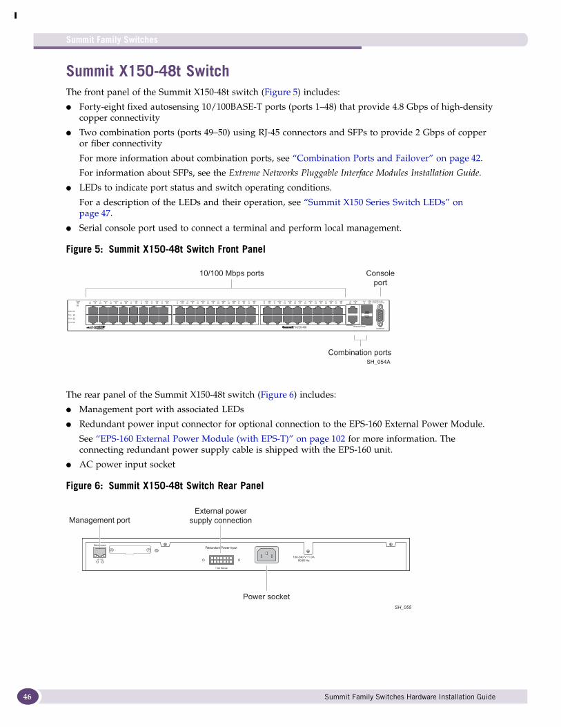
Summit X150-48t SwitchThe front panel of the Summit X150-48t switch (Figure 5) includes:
● Forty-eight fixed autosensing 10/100BASE-T ports (ports 1–48) that provide 4.8 Gbps of high-density copper connectivity
● Two combination ports (ports 49–50) using RJ-45 connectors and SFPs to provide 2 Gbps of copper or fiber connectivity
For more information about combination ports, see “Combination Ports and Failover” on page 42.
For information about SFPs, see the Extreme Networks Pluggable Interface Modules Installation Guide.
● LEDs to indicate port status and switch operating conditions.
For a description of the LEDs and their operation, see “Summit X150 Series Switch LEDs” on page 47.
● Serial console port used to connect a terminal and perform local management.
Figure 5: Summit X150-48t Switch Front Panel
The rear panel of the Summit X150-48t switch (Figure 6) includes:
● Management port with associated LEDs
● Redundant power input connector for optional connection to the EPS-160 External Power Module.
See “EPS-160 External Power Module (with EPS-T)” on page 102 for more information. The connecting redundant power supply cable is shipped with the EPS-160 unit.
● AC power input socket
Figure 6: Summit X150-48t Switch Rear Panel
SH_054A
10/100 Mbps ports Consoleport
Combination ports
SH_055
Management port
Power socket
External powersupply connection
Summit Family Switches Hardware Installation Guide
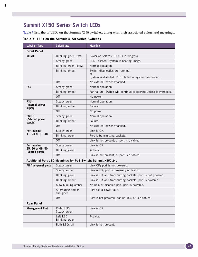
Summit X150 Series Switch LEDsTable 7 lists the of LEDs on the Summit X150 switches, along with their associated colors and meanings..
Table 7: LEDs on the Summit X150 Series Switches
Label or Type Color/State Meaning
Front PanelMGMT Blinking green (fast) Power-on self-test (POST) in progress.
Steady green POST passed. System is booting image.
Blinking green (slow) Normal operation.
Blinking amber Switch diagnostics are running.orSystem is disabled. POST failed or system overheated.
Off No external power attached.
FAN Steady green Normal operation.
Blinking amber Fan failure. Switch will continue to operate unless it overheats.
Off No power.
PSU-I(Internal power supply)
Steady green Normal operation.
Blinking amber Failure.
Off No power.
PSU-E (External power supply)
Steady green Normal operation.
Blinking amber Failure.
Off No external power attached.
Port number1 – 24 or 1 – 48
Steady green Link is OK.
Blinking green Port is transmitting packets.
Off Link is not present, or port is disabled.
Port number25, 26 or 49, 50(Shared ports)
Steady green Link is OK.
Blinking green Activity.
Off Link is not present, or port is disabled.
Additional Port LED Meanings for PoE Switch: Summit X150-24pAll front-panel ports Steady green Link OK; port is not powered.
Steady amber Link is OK; port is powered; no traffic.
Blinking green Link is OK and transmitting packets; port is not powered.
Blinking amber Link is OK and transmitting packets; port is powered.
Slow blinking amber No link, or disabled port; port is powered.
Alternating amber and green
Port has a power fault.
Off Port is not powered, has no link, or is disabled.
Rear PanelManagement Port Right LED:
Steady greenLink is OK.
Left LED:Blinking green
Activity.
Both LEDs off Link is not present.
Summit Family Switches Hardware Installation Guide 47
Summit Family Switches
48
Summit X250e Series SwitchesThe Summit X250e series switches provide 24 or 48 Ethernet ports that deliver high-density fast Ethernet connectivity using fixed 10/100/1000BASE-T ports or installable small form pluggable (SFP) optical modules. Fixed-port models are available either with or without PoE. Each Summit X250e series switch has two combination ports that provide 10/100/1000 BASE-T or SFP connectivity for 2 Gbps of copper or fiber connectivity. A serial console port on the front panel allows you to connect a terminal and perform local management. An Ethernet management port can be used to connect the system to a parallel management network for administration. Alternatively, you can use an Ethernet cable to connect this port directly to a laptop to view and locally manage the switch configurations.
On the back of the switch, two high-speed stacking ports allow you to combine multiple units into a single SummitStack management entity. The rear panel also provides an AC or DC power input socket and a redundant power connector. (See specific switch descriptions for more information about the power options.) The switch automatically adjusts to the supply voltage. The redundant power connector allows you to connect the switch to the EPS-160, EPS-500, or EPS-150DC external power supply. When a compatible external power supply is used with the Summit X250e series switch, the internal and external power supplies are fully fault tolerant and load-sharing. If one power supply fails, the other power supply will provide sufficient power to operate the switch.
The Summit X250e series switches include the following switches:
● Summit X250e-24t Switch
● Summit X250e-24t-TAA Switch
● Summit X250e-24tDC Switch
● Summit X250e-24tDC-TAA Switch
● Summit X250e-24p Switch
● Summit X250e-24p-TAA Switch
● Summit X250e-24x Switch
● Summit X250e-24x-TAA Switch
● Summit X250e-24xDC Switch
● Summit X250e-24x-TAA Switch
● Summit X250e-48t Switch
● Summit X250e-48t-TAA Switch
● Summit X250e-48tDC Switch
● Summit X250e-48tDC-TAA Switch
● Summit X250e-48p Switch
● Summit X250e-48p-TAA Switch
NOTE
In the descriptions that follow, references to a Summit X250e series model number also apply to the equivalent TAA-compliant switch version.
Summit Family Switches Hardware Installation Guide
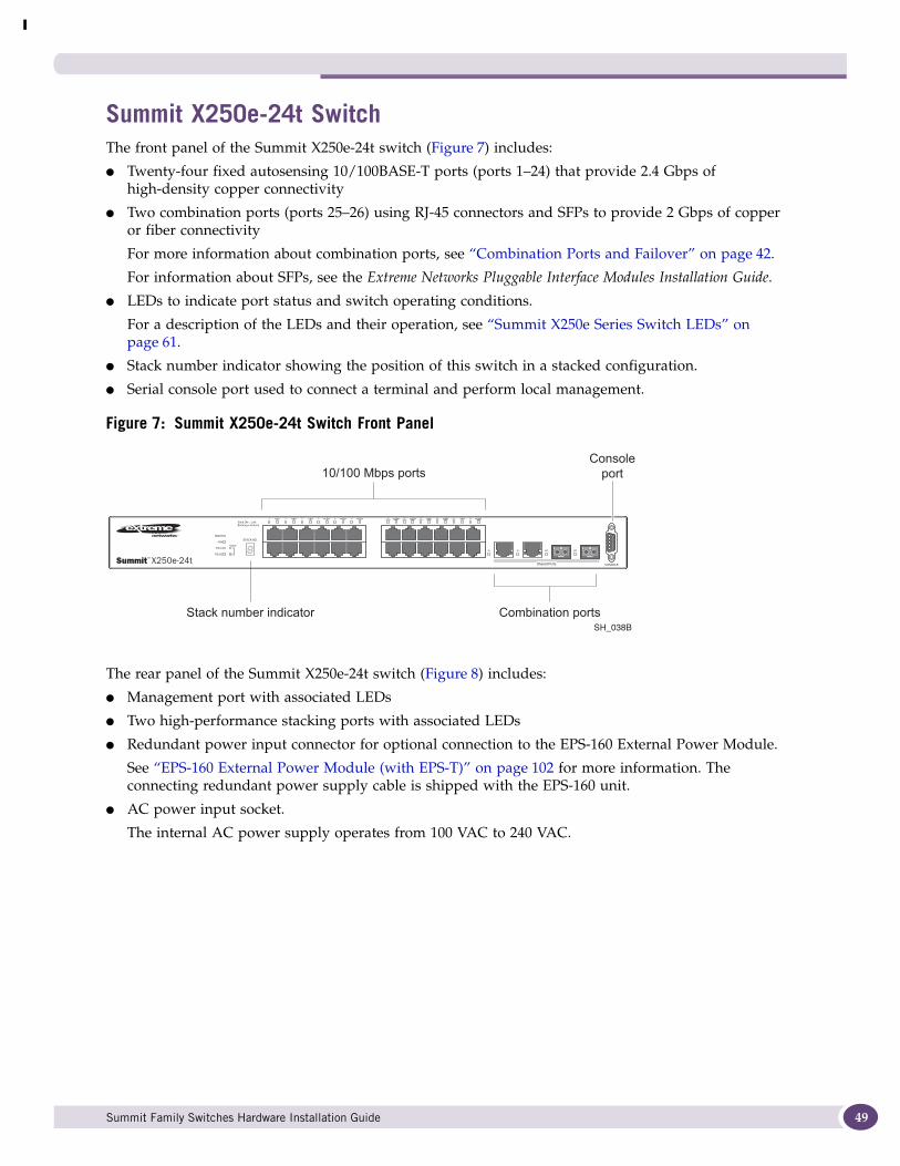
Summit X250e-24t SwitchThe front panel of the Summit X250e-24t switch (Figure 7) includes:
● Twenty-four fixed autosensing 10/100BASE-T ports (ports 1–24) that provide 2.4 Gbps of high-density copper connectivity
● Two combination ports (ports 25–26) using RJ-45 connectors and SFPs to provide 2 Gbps of copper or fiber connectivity
For more information about combination ports, see “Combination Ports and Failover” on page 42.
For information about SFPs, see the Extreme Networks Pluggable Interface Modules Installation Guide.
● LEDs to indicate port status and switch operating conditions.
For a description of the LEDs and their operation, see “Summit X250e Series Switch LEDs” on page 61.
● Stack number indicator showing the position of this switch in a stacked configuration.
● Serial console port used to connect a terminal and perform local management.
Figure 7: Summit X250e-24t Switch Front Panel
The rear panel of the Summit X250e-24t switch (Figure 8) includes:
● Management port with associated LEDs
● Two high-performance stacking ports with associated LEDs
● Redundant power input connector for optional connection to the EPS-160 External Power Module.
See “EPS-160 External Power Module (with EPS-T)” on page 102 for more information. The connecting redundant power supply cable is shipped with the EPS-160 unit.
● AC power input socket.
The internal AC power supply operates from 100 VAC to 240 VAC.
1
2
Stack
SH_038B
10/100 Mbps portsConsole
port
Combination portsStack number indicator
Summit Family Switches Hardware Installation Guide 49

Summit Family Switches
50
Figure 8: Summit X250e-24t Switch Rear Panel
Summit X250e-24tDC SwitchThe front panel of the Summit X250e-24tDC switch (Figure 33) includes:
● Twenty-four fixed autosensing 10/100BASE-T ports (ports 1–24) that provide 2.4 Gbps of high-density copper connectivity
● Two combination ports (ports 25–26) using RJ-45 connectors and SFPs to provide 2 Gbps of copper or fiber connectivity
For more information about combination ports, see “Combination Ports and Failover” on page 42.
For information about SFPs, see the Extreme Networks Pluggable Interface Modules Installation Guide.
● LEDs to indicate port status and switch operating conditions.
For a description of the LEDs and their operation, see “Summit X250e Series Switch LEDs” on page 61.
● Stack number indicator showing the position of this switch in a stacked configuration.
● Serial console port used to connect a terminal and perform local management.
Figure 9: Summit X250e-24tDC Switch Front Panel
The rear panel of the Summit X250e-24tDC switch (Figure 34) includes:
● Ethernet management port with associated LEDs
● Two high-performance stacking ports with associated LEDs
● Redundant power input connector for optional connection to the EPS-150DC External Power Module (Model No. 10909).
See “EPS-150DC External Power Module (with EPS-T2)” on page 104 for more information. The connecting redundant power supply cable is shipped with the EPS-150DC unit.
SH_039
Redundant Power Input
! See Manual
10 Gigabitstacking ports
Management port
Power socket
External powersupply connection
1
2
Stack
SH_057_front_x250e-24tdc
10/100 Mbps portsConsole
port
Combination portsStack number indicator
DC
Summit Family Switches Hardware Installation Guide
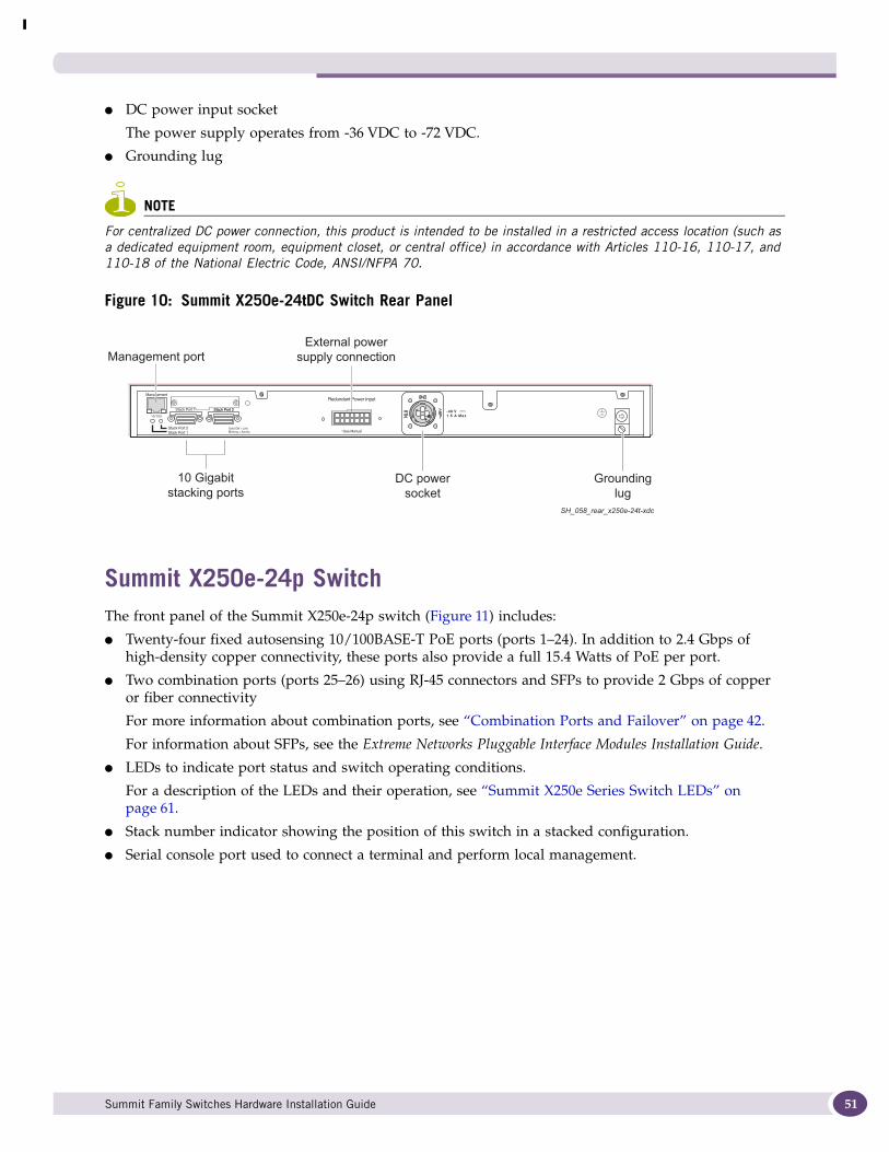
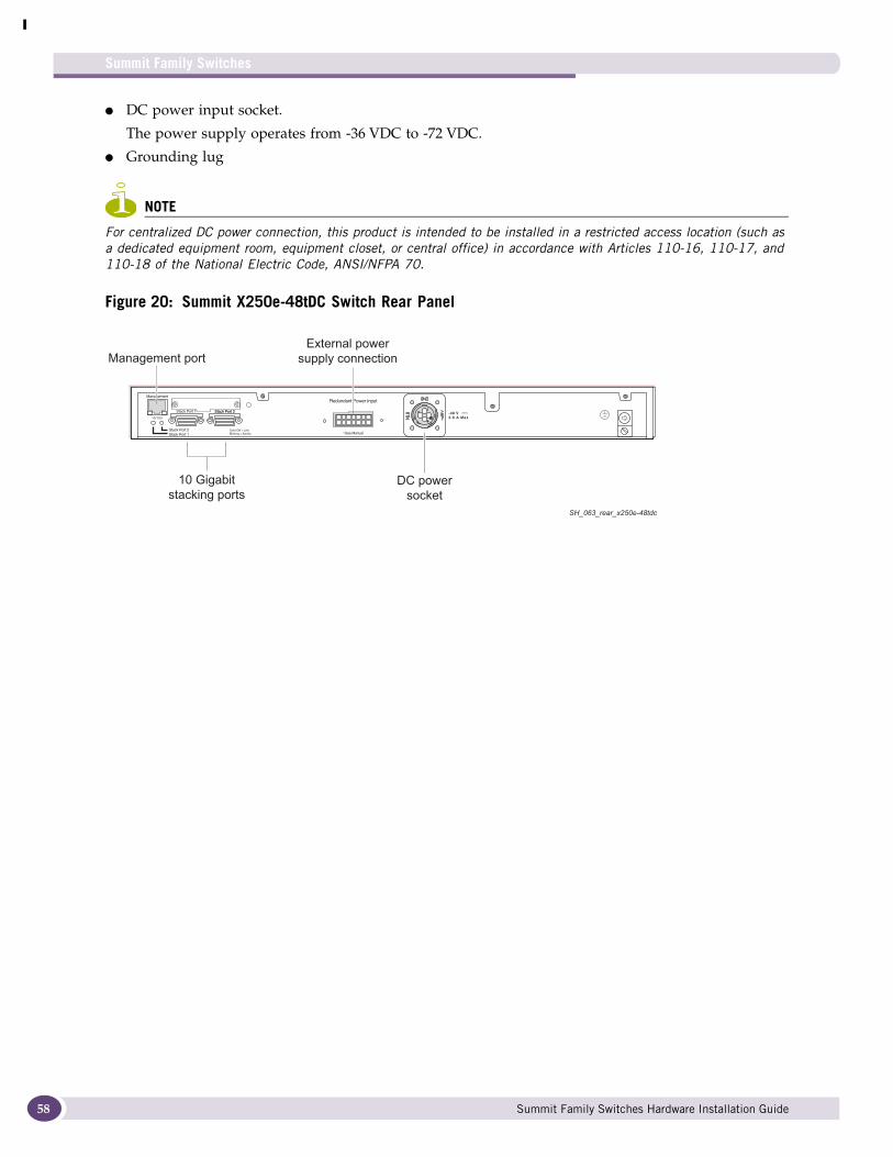
● DC power input socket
The power supply operates from -36 VDC to -72 VDC.
● Grounding lug
NOTE
For centralized DC power connection, this product is intended to be installed in a restricted access location (such as a dedicated equipment room, equipment closet, or central office) in accordance with Articles 110-16, 110-17, and 110-18 of the National Electric Code, ANSI/NFPA 70.
Figure 10: Summit X250e-24tDC Switch Rear Panel
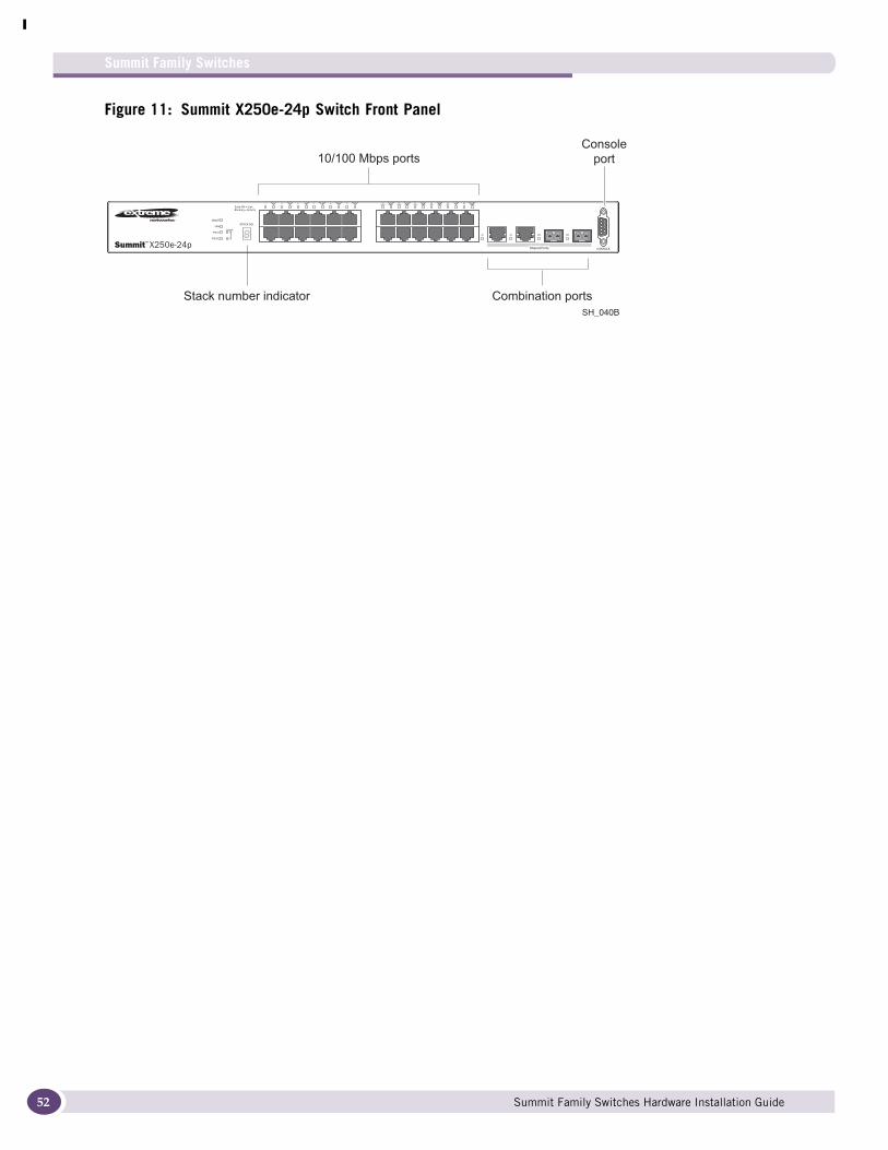
Summit X250e-24p SwitchThe front panel of the Summit X250e-24p switch (Figure 11) includes:
● Twenty-four fixed autosensing 10/100BASE-T PoE ports (ports 1–24). In addition to 2.4 Gbps of high-density copper connectivity, these ports also provide a full 15.4 Watts of PoE per port.
● Two combination ports (ports 25–26) using RJ-45 connectors and SFPs to provide 2 Gbps of copper or fiber connectivity
For more information about combination ports, see “Combination Ports and Failover” on page 42.
For information about SFPs, see the Extreme Networks Pluggable Interface Modules Installation Guide.
● LEDs to indicate port status and switch operating conditions.
For a description of the LEDs and their operation, see “Summit X250e Series Switch LEDs” on page 61.
● Stack number indicator showing the position of this switch in a stacked configuration.
● Serial console port used to connect a terminal and perform local management.
SH_058_rear_x250e-24t-xdc
Redundant Power Input
! See Manual
10 Gigabitstacking ports
Management portExternal power
supply connection
-48 V1.5 A Max
DC powersocket
Groundinglug
Summit Family Switches Hardware Installation Guide 51
Summit Family Switches
52
Figure 11: Summit X250e-24p Switch Front Panel
1
2
Stack
SH_040B
10/100 Mbps portsConsole
port
Combination portsStack number indicator
Summit Family Switches Hardware Installation Guide
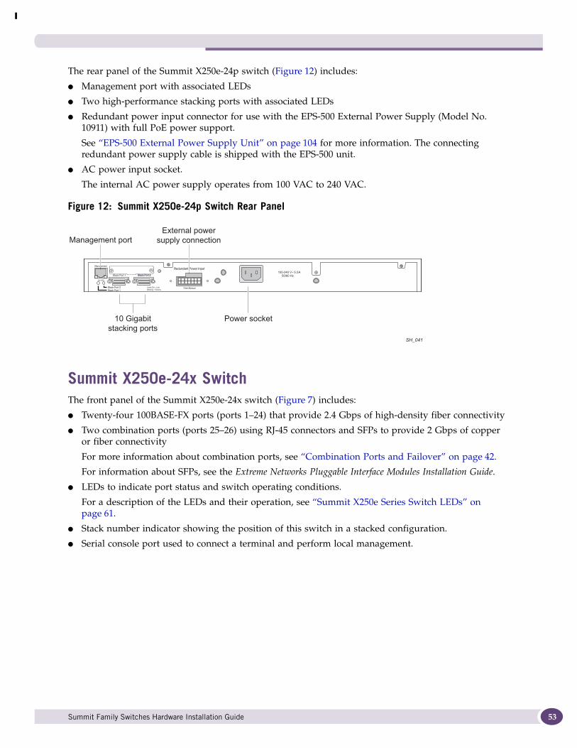
The rear panel of the Summit X250e-24p switch (Figure 12) includes:
● Management port with associated LEDs
● Two high-performance stacking ports with associated LEDs
● Redundant power input connector for use with the EPS-500 External Power Supply (Model No. 10911) with full PoE power support.
See “EPS-500 External Power Supply Unit” on page 104 for more information. The connecting redundant power supply cable is shipped with the EPS-500 unit.
● AC power input socket.
The internal AC power supply operates from 100 VAC to 240 VAC.
Figure 12: Summit X250e-24p Switch Rear Panel
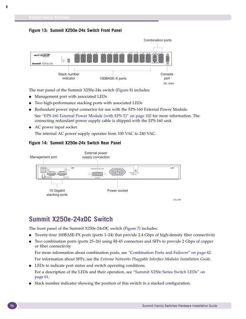
Summit X250e-24x SwitchThe front panel of the Summit X250e-24x switch (Figure 7) includes:
● Twenty-four 100BASE-FX ports (ports 1–24) that provide 2.4 Gbps of high-density fiber connectivity
● Two combination ports (ports 25–26) using RJ-45 connectors and SFPs to provide 2 Gbps of copper or fiber connectivity
For more information about combination ports, see “Combination Ports and Failover” on page 42.
For information about SFPs, see the Extreme Networks Pluggable Interface Modules Installation Guide.
● LEDs to indicate port status and switch operating conditions.
For a description of the LEDs and their operation, see “Summit X250e Series Switch LEDs” on page 61.
● Stack number indicator showing the position of this switch in a stacked configuration.
● Serial console port used to connect a terminal and perform local management.
10 Gigabitstacking ports
Management port
Power socket
External powersupply connection
SH_041
Summit Family Switches Hardware Installation Guide 53
Summit Family Switches
54
Figure 13: Summit X250e-24x Switch Front Panel
The rear panel of the Summit X250e-24x switch (Figure 8) includes:
● Management port with associated LEDs
● Two high-performance stacking ports with associated LEDs
● Redundant power input connector for use with the EPS-160 External Power Module.
See “EPS-160 External Power Module (with EPS-T)” on page 102 for more information. The connecting redundant power supply cable is shipped with the EPS-160 unit.
● AC power input socket.
The internal AC power supply operates from 100 VAC to 240 VAC.
Figure 14: Summit X250e-24x Switch Rear Panel
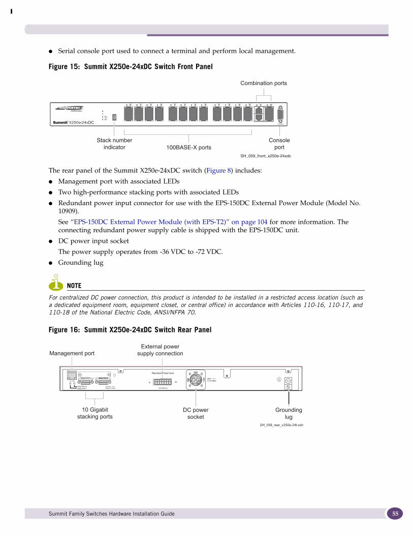
Summit X250e-24xDC SwitchThe front panel of the Summit X250e-24xDC switch (Figure 7) includes:
● Twenty-four 100BASE-FX ports (ports 1–24) that provide 2.4 Gbps of high-density fiber connectivity
● Two combination ports (ports 25–26) using RJ-45 connectors and SFPs to provide 2 Gbps of copper or fiber connectivity
For more information about combination ports, see “Combination Ports and Failover” on page 42.
For information about SFPs, see the Extreme Networks Pluggable Interface Modules Installation Guide.
● LEDs to indicate port status and switch operating conditions.
For a description of the LEDs and their operation, see “Summit X250e Series Switch LEDs” on page 61.
● Stack number indicator showing the position of this switch in a stacked configuration.
SH_056A
100BASE-X ports
Combination ports
Consoleport
Stack numberindicator
SH_039
Redundant Power Input
! See Manual
10 Gigabitstacking ports
Management port
Power socket
External powersupply connection
Summit Family Switches Hardware Installation Guide
● Serial console port used to connect a terminal and perform local management.
Figure 15: Summit X250e-24xDC Switch Front Panel
The rear panel of the Summit X250e-24xDC switch (Figure 8) includes:
● Management port with associated LEDs
● Two high-performance stacking ports with associated LEDs
● Redundant power input connector for use with the EPS-150DC External Power Module (Model No. 10909).
See “EPS-150DC External Power Module (with EPS-T2)” on page 104 for more information. The connecting redundant power supply cable is shipped with the EPS-150DC unit.
● DC power input socket
The power supply operates from -36 VDC to -72 VDC.
● Grounding lug
NOTE
For centralized DC power connection, this product is intended to be installed in a restricted access location (such as a dedicated equipment room, equipment closet, or central office) in accordance with Articles 110-16, 110-17, and 110-18 of the National Electric Code, ANSI/NFPA 70.
Figure 16: Summit X250e-24xDC Switch Rear Panel
SH_059_front_x250e-24xdc
100BASE-X ports
Combination ports
Consoleport
Stack numberindicator
DC
SH_058_rear_x250e-24t-xdc
Redundant Power Input
! See Manual
10 Gigabitstacking ports
Management portExternal power
supply connection
-48 V1.5 A Max
DC powersocket
Groundinglug
Summit Family Switches Hardware Installation Guide 55

Summit Family Switches
56
Summit X250e-48t SwitchThe front panel of the Summit X250e-48t switch (Figure 17):
● Forty-eight fixed autosensing 10/100BASE-T ports (ports 1–48) that provide 4.8 Gps of high-density copper connectivity
● Two combination ports (ports 49–50) using RJ-45 connectors and SFPs to provide 2 Gbps of copper or fiber connectivity
For more information about combination ports, see “Combination Ports and Failover” on page 42.
For information about SFPs, see the Extreme Networks Pluggable Interface Modules Installation Guide.
● LEDs to indicate port status and switch operating conditions.
For a description of the LEDs and their operation, see “Summit X250e Series Switch LEDs” on page 61.
● Stack number indicator showing the position of this switch in a stacked configuration.
● Serial console port used to connect a terminal and perform local management.
Figure 17: Summit X250e-48t Switch Front Panel
The rear panel of the Summit X250e-48t switch (Figure 18) includes:
● Management port with associated LEDs
● Two high-performance stacking ports with associated LEDs
● Redundant power input connector for optional connection to the EPS-160 External Power Module.
See “EPS-160 External Power Module (with EPS-T)” on page 102 for more information. The connecting redundant power supply cable is shipped with the EPS-160 unit.
● AC power input socket.
The internal AC power supply operates from 100 VAC to 240 VAC.
SH_044B
10/100 Mbps ports Consoleport
Combination portsStack number indicator
Summit Family Switches Hardware Installation Guide
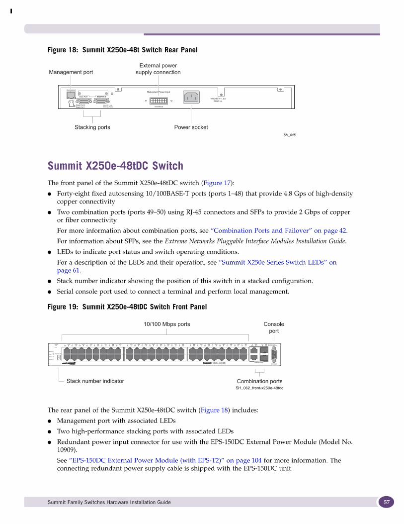
Figure 18: Summit X250e-48t Switch Rear Panel
Summit X250e-48tDC SwitchThe front panel of the Summit X250e-48tDC switch (Figure 17):
● Forty-eight fixed autosensing 10/100BASE-T ports (ports 1–48) that provide 4.8 Gps of high-density copper connectivity
● Two combination ports (ports 49–50) using RJ-45 connectors and SFPs to provide 2 Gbps of copper or fiber connectivity
For more information about combination ports, see “Combination Ports and Failover” on page 42.
For information about SFPs, see the Extreme Networks Pluggable Interface Modules Installation Guide.
● LEDs to indicate port status and switch operating conditions.
For a description of the LEDs and their operation, see “Summit X250e Series Switch LEDs” on page 61.
● Stack number indicator showing the position of this switch in a stacked configuration.
● Serial console port used to connect a terminal and perform local management.
Figure 19: Summit X250e-48tDC Switch Front Panel
The rear panel of the Summit X250e-48tDC switch (Figure 18) includes:
● Management port with associated LEDs
● Two high-performance stacking ports with associated LEDs
● Redundant power input connector for use with the EPS-150DC External Power Module (Model No. 10909).
See “EPS-150DC External Power Module (with EPS-T2)” on page 104 for more information. The connecting redundant power supply cable is shipped with the EPS-150DC unit.
SH_045
Stacking ports
Management port
Power socket
External powersupply connection
SH_062_front-x250e-48tdc
10/100 Mbps ports Consoleport
Combination portsStack number indicator
Summit Family Switches Hardware Installation Guide 57
Summit Family Switches
58
● DC power input socket.
The power supply operates from -36 VDC to -72 VDC.
● Grounding lug
NOTE
For centralized DC power connection, this product is intended to be installed in a restricted access location (such as a dedicated equipment room, equipment closet, or central office) in accordance with Articles 110-16, 110-17, and 110-18 of the National Electric Code, ANSI/NFPA 70.
Figure 20: Summit X250e-48tDC Switch Rear Panel
SH_063_rear_x250e-48tdc
Redundant Power Input
! See Manual
10 Gigabitstacking ports
Management portExternal power
supply connection
-48 V2.0 A Max
DC powersocket
Summit Family Switches Hardware Installation Guide
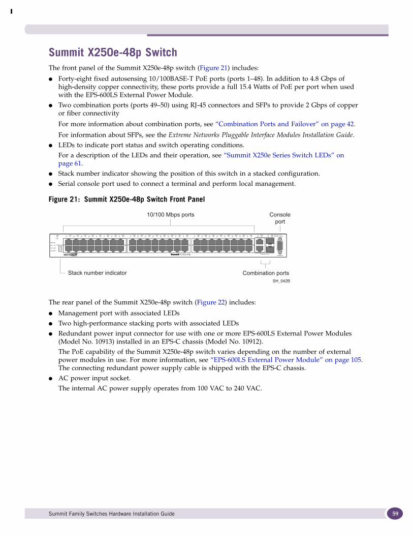
Summit X250e-48p SwitchThe front panel of the Summit X250e-48p switch (Figure 21) includes:
● Forty-eight fixed autosensing 10/100BASE-T PoE ports (ports 1–48). In addition to 4.8 Gbps of high-density copper connectivity, these ports provide a full 15.4 Watts of PoE per port when used with the EPS-600LS External Power Module.
● Two combination ports (ports 49–50) using RJ-45 connectors and SFPs to provide 2 Gbps of copper or fiber connectivity
For more information about combination ports, see “Combination Ports and Failover” on page 42.
For information about SFPs, see the Extreme Networks Pluggable Interface Modules Installation Guide.● LEDs to indicate port status and switch operating conditions.
For a description of the LEDs and their operation, see “Summit X250e Series Switch LEDs” on page 61.
● Stack number indicator showing the position of this switch in a stacked configuration.● Serial console port used to connect a terminal and perform local management.
Figure 21: Summit X250e-48p Switch Front Panel
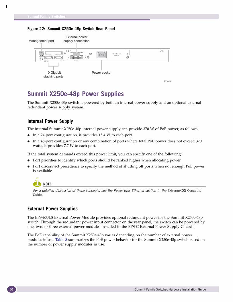
The rear panel of the Summit X250e-48p switch (Figure 22) includes:
● Management port with associated LEDs● Two high-performance stacking ports with associated LEDs● Redundant power input connector for use with one or more EPS-600LS External Power Modules
(Model No. 10913) installed in an EPS-C chassis (Model No. 10912). The PoE capability of the Summit X250e-48p switch varies depending on the number of external power modules in use. For more information, see “EPS-600LS External Power Module” on page 105. The connecting redundant power supply cable is shipped with the EPS-C chassis.
● AC power input socket. The internal AC power supply operates from 100 VAC to 240 VAC.
SH_042B
10/100 Mbps ports Consoleport
Combination portsStack number indicator
Summit Family Switches Hardware Installation Guide 59
Summit Family Switches
60
Figure 22: Summit X250e-48p Switch Rear Panel
Summit X250e-48p Power SuppliesThe Summit X250e-48p switch is powered by both an internal power supply and an optional external redundant power supply system.
Internal Power SupplyThe internal Summit X250e-48p internal power supply can provide 370 W of PoE power, as follows:
● In a 24-port configuration, it provides 15.4 W to each port
● In a 48-port configuration or any combination of ports where total PoE power does not exceed 370 watts, it provides 7.7 W to each port.
If the total system demands exceed this power limit, you can specify one of the following:
● Port priorities to identify which ports should be ranked higher when allocating power
● Port disconnect precedence to specify the method of shutting off ports when not enough PoE power is available
NOTE
For a detailed discussion of these concepts, see the Power over Ethernet section in the ExtremeXOS Concepts Guide.
External Power Supplies
The EPS-600LS External Power Module provides optional redundant power for the Summit X250e-48p switch. Through the redundant power input connector on the rear panel, the switch can be powered by one, two, or three external power modules installed in the EPS-C External Power Supply Chassis.
The PoE capability of the Summit X250e-48p varies depending on the number of external power modules in use. Table 8 summarizes the PoE power behavior for the Summit X250e-48p switch based on the number of power supply modules in use.
10 Gigabitstacking ports
Management port
Power socket
External powersupply connection
SH 043
Summit Family Switches Hardware Installation Guide
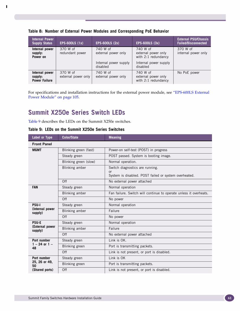
For specifications and installation instructions for the external power module, see “EPS-600LS External Power Module” on page 105.
Summit X250e Series Switch LEDsTable 9 describes the LEDs on the Summit X250e switches.
Table 8: Number of External Power Modules and Corresponding PoE Behavior
Internal Power Supply Status EPS-600LS (1x) EPS-600LS (2x) EPS-600LS (3x)
External PSU/Chassis Failed/Disconnected
Internal power supply: Power on
370 W of redundant power
740 W of external power only
Internal power supply disabled
740 W of external power only with 2:1 redundancy
Internal power supply disabled
370 W of internal power only
Internal power supply: Power Failure
370 W of external power only
740 W of external power only
740 W of external power only with 2:1 redundancy
No PoE power
Table 9: LEDs on the Summit X250e Series Switches
Label or Type Color/State Meaning
Front PanelMGMT Blinking green (fast) Power-on self-test (POST) in progress
Steady green POST passed. System is booting image.
Blinking green (slow) Normal operation.
Blinking amber Switch diagnostics are running.orSystem is disabled. POST failed or system overheated.
Off No external power attached
FAN Steady green Normal operation
Blinking amber Fan failure. Switch will continue to operate unless it overheats.
Off No power
PSU-I(Internal power supply)
Steady green Normal operation
Blinking amber Failure
Off No power
PSU-E (External power supply)
Steady green Normal operation
Blinking amber Failure
Off No external power attached
Port number1 – 24 or 1 – 48
Steady green Link is OK.
Blinking green Port is transmitting packets.
Off Link is not present, or port is disabled.
Port number25, 26 or 49, 50(Shared ports)
Steady green Link is OK
Blinking green Port is transmitting packets.
Off Link is not present, or port is disabled.
Summit Family Switches Hardware Installation Guide 61
Summit Family Switches
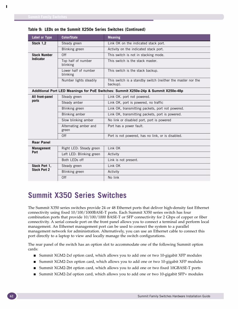
62
Summit X350 Series SwitchesThe Summit X350 series switches provide 24 or 48 Ethernet ports that deliver high-density fast Ethernet connectivity using fixed 10/100/1000BASE-T ports. Each Summit X350 series switch has four combination ports that provide 10/100/1000 BASE-T or SFP connectivity for 2 Gbps of copper or fiber connectivity. A serial console port on the front panel allows you to connect a terminal and perform local management. An Ethernet management port can be used to connect the system to a parallel management network for administration. Alternatively, you can use an Ethernet cable to connect this port directly to a laptop to view and locally manage the switch configurations.
The rear panel of the switch has an option slot to accommodate one of the following Summit option cards:
■ Summit XGM2-2xf option card, which allows you to add one or two 10-gigabit XFP modules
■ Summit XGM2-2xn option card, which allows you to add one or two 10-gigabit XFP modules
■ Summit XGM2-2bt option card, which allows you to add one or two fixed 10GBASE-T ports
■ Summit XGM2-2sf option card, which allows you to add one or two 10-gigabit SFP+ modules
Stack 1,2 Steady green Link OK on the indicated stack port.
Blinking green Activity on the indicated stack port.
Stack Number Indicator
Off This switch is not in stacking mode.
Top half of number blinking
This switch is the stack master.
Lower half of number blinking
This switch is the stack backup.
Number lights steadily This switch is a standby switch (neither the master nor the backup).
Additional Port LED Meanings for PoE Switches: Summit X250e-24p & Summit X250e-48pAll front-panel ports
Steady green Link OK. port not powered.
Steady amber Link OK, port is powered, no traffic
Blinking green Link OK, transmitting packets, port not powered.
Blinking amber Link OK, transmitting packets, port is powered.
Slow blinking amber No link or disabled port, port is powered
Alternating amber and green
Port has a power fault.
Off Port is not powered, has no link, or is disabled.
Rear PanelManagement Port
Right LED: Steady green Link OK
Left LED: Blinking green Activity
Both LEDs off Link is not present.
Stack Port 1, Stack Port 2
Steady green Link OK
Blinking green Activity
Off No link
Table 9: LEDs on the Summit X250e Series Switches (Continued)
Label or Type Color/State Meaning
Summit Family Switches Hardware Installation Guide
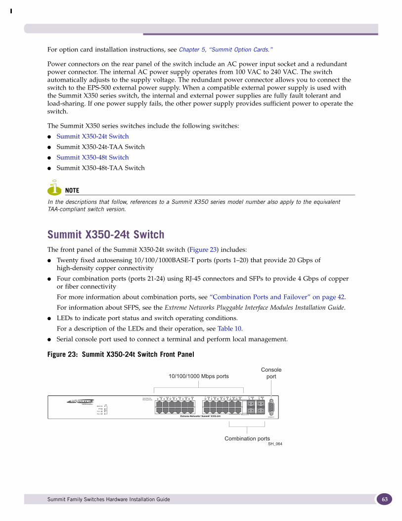
For option card installation instructions, see Chapter 5, “Summit Option Cards.”
Power connectors on the rear panel of the switch include an AC power input socket and a redundant power connector. The internal AC power supply operates from 100 VAC to 240 VAC. The switch automatically adjusts to the supply voltage. The redundant power connector allows you to connect the switch to the EPS-500 external power supply. When a compatible external power supply is used with the Summit X350 series switch, the internal and external power supplies are fully fault tolerant and load-sharing. If one power supply fails, the other power supply provides sufficient power to operate the switch.
The Summit X350 series switches include the following switches:
● Summit X350-24t Switch
● Summit X350-24t-TAA Switch
● Summit X350-48t Switch
● Summit X350-48t-TAA Switch
NOTE
In the descriptions that follow, references to a Summit X350 series model number also apply to the equivalent TAA-compliant switch version.
Summit X350-24t SwitchThe front panel of the Summit X350-24t switch (Figure 23) includes:
● Twenty fixed autosensing 10/100/1000BASE-T ports (ports 1–20) that provide 20 Gbps of high-density copper connectivity
● Four combination ports (ports 21-24) using RJ-45 connectors and SFPs to provide 4 Gbps of copper or fiber connectivity
For more information about combination ports, see “Combination Ports and Failover” on page 42.
For information about SFPS, see the Extreme Networks Pluggable Interface Modules Installation Guide.
● LEDs to indicate port status and switch operating conditions.
For a description of the LEDs and their operation, see Table 10.
● Serial console port used to connect a terminal and perform local management.
Figure 23: Summit X350-24t Switch Front Panel
SH_064
10/100/1000 Mbps ports
Combination ports
Consoleport
Summit Family Switches Hardware Installation Guide 63
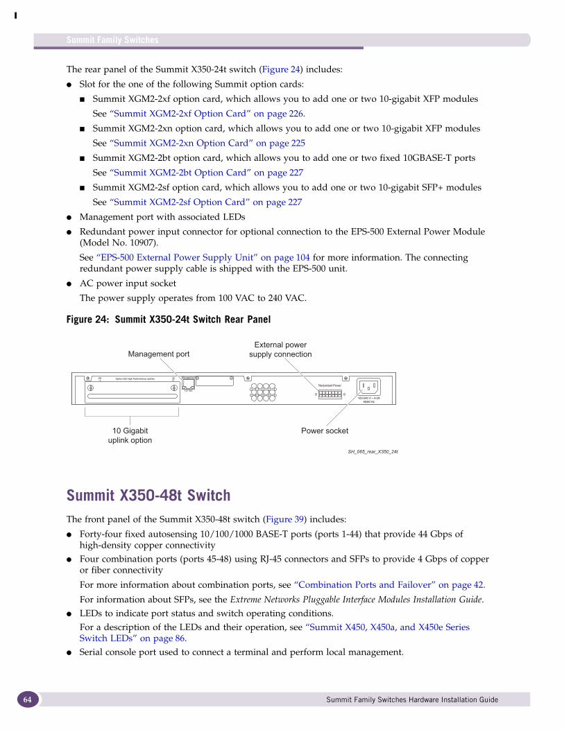
Summit Family Switches
64
The rear panel of the Summit X350-24t switch (Figure 24) includes:
● Slot for the one of the following Summit option cards:
■ Summit XGM2-2xf option card, which allows you to add one or two 10-gigabit XFP modules
See “Summit XGM2-2xf Option Card” on page 226.
■ Summit XGM2-2xn option card, which allows you to add one or two 10-gigabit XFP modules
See “Summit XGM2-2xn Option Card” on page 225
■ Summit XGM2-2bt option card, which allows you to add one or two fixed 10GBASE-T ports
See “Summit XGM2-2bt Option Card” on page 227
■ Summit XGM2-2sf option card, which allows you to add one or two 10-gigabit SFP+ modules
See “Summit XGM2-2sf Option Card” on page 227
● Management port with associated LEDs
● Redundant power input connector for optional connection to the EPS-500 External Power Module (Model No. 10907).
See “EPS-500 External Power Supply Unit” on page 104 for more information. The connecting redundant power supply cable is shipped with the EPS-500 unit.
● AC power input socket
The power supply operates from 100 VAC to 240 VAC.
Figure 24: Summit X350-24t Switch Rear Panel
Summit X350-48t SwitchThe front panel of the Summit X350-48t switch (Figure 39) includes:
● Forty-four fixed autosensing 10/100/1000 BASE-T ports (ports 1-44) that provide 44 Gbps of high-density copper connectivity
● Four combination ports (ports 45-48) using RJ-45 connectors and SFPs to provide 4 Gbps of copper or fiber connectivity
For more information about combination ports, see “Combination Ports and Failover” on page 42.
For information about SFPs, see the Extreme Networks Pluggable Interface Modules Installation Guide.● LEDs to indicate port status and switch operating conditions.
For a description of the LEDs and their operation, see “Summit X450, X450a, and X450e Series Switch LEDs” on page 86.
● Serial console port used to connect a terminal and perform local management.
SH_065_rear_X350_24t
10 Gigabituplink option
Management port
Power socket
External powersupply connection
Summit Family Switches Hardware Installation Guide
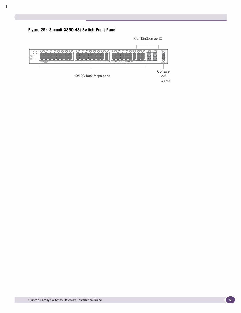
Figure 25: Summit X350-48t Switch Front Panel
Stack 10G
MGMT
FAN
PSU-1
PSU-E
Band On = LinkBlinking = Activity
21
12
12
43 65 87 109 1211 1413 1615 1817 2019 2221 2423 2625 2827 3029 3231 3433 3635 3837 4039 4241 4443 4645 4847 46X45X 48X47X
Shared Ports
SH_066
Combination ports
10/100/1000 Mbps portsConsole
port
Summit Family Switches Hardware Installation Guide 65

Summit Family Switches
66
The rear panel of the Summit X350-48t switch (Figure 40) includes:
● Slot for the one of the following Summit option cards:
■ Summit XGM2-2xn option card, which allows you to add one or two 10-gigabit XFP modules
See “Summit XGM2-2xn Option Card” on page 225.
■ Summit XGM2-2xf option card, which allows you to add one or two 10-gigabit XFP modules
See “Summit XGM2-2xf Option Card” on page 226.
■ Summit XGM2-2sf option card, which allows you to add one or two 10-gigabit SFP+ modules
See “Summit XGM2-2sf Option Card” on page 227.
■ Summit XGM2-2bt option card, which allows you to add one or two fixed 10GBASE-T ports
See “Summit XGM2-2bt Option Card” on page 227.
● Management port with associated LEDs ● Redundant power input connector for optional connection to the EPS-500 External Power Supply
Unit (Model No. 10911). See “EPS-500 External Power Supply Unit” on page 104 for more information. The connecting redundant power supply cable is shipped with the EPS-500 power supply.
● AC power input socketThe power supply operates from 100 VAC to 240 VAC.
Figure 26: Summit X350-48t Switch Rear Panel
SH_067_rear_X350-48t
10 Gigabituplink option
Management port
Power socket
External powersupply connection
Summit Family Switches Hardware Installation Guide
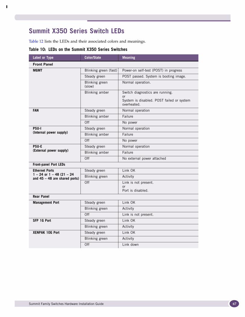
Summit X350 Series Switch LEDsTable 12 lists the LEDs and their associated colors and meanings.
Table 10: LEDs on the Summit X350 Series Switches
Label or Type Color/State Meaning
Front PanelMGMT Blinking green (fast) Power-on self-test (POST) in progress
Steady green POST passed. System is booting image.
Blinking green (slow)
Normal operation.
Blinking amber Switch diagnostics are running.orSystem is disabled. POST failed or system overheated.
FAN Steady green Normal operation
Blinking amber Failure
Off No power
PSU-I (Internal power supply)
Steady green Normal operation
Blinking amber Failure
Off No power
PSU-E (External power supply)
Steady green Normal operation
Blinking amber Failure
Off No external power attached
Front-panel Port LEDs
Ethernet Ports1 – 24 or 1 – 48 (21 – 24 and 45 – 48 are shared ports)
Steady green Link OK
Blinking green Activity
Off Link is not present.orPort is disabled.
Rear Panel
Management Port Steady green Link OK
Blinking green Activity
Off Link is not present.
SFP 1G Port Steady green Link OK
Blinking green Activity
XENPAK 10G Port Steady green Link OK
Blinking green Activity
Off Link down
Summit Family Switches Hardware Installation Guide 67

Summit Family Switches
68
Summit X450, X450a, and X450e Series SwitchesThe Summit X450 series, Summit X450a series, and Summit X450e series switches provide 24 or 48 Ethernet ports. These switches deliver high-density fast Ethernet connectivity using fixed 10/100/1000BASE-T ports or installable small form pluggable (SFP) optical modules. Models in different series are available both with and without PoE and in AC or DC power versions.
Each Summit X450, X450a, or X450e series switch has four combination ports that provide 10/100/1000 BASE-T or SFP connectivity for 4 Gbps of copper or fiber connectivity. A serial console port on the front panel allows you to connect a terminal and perform local management. An Ethernet management port on the back panel can be used to connect the system to a parallel management network for administration. Alternatively, you can use an Ethernet cable to connect the Ethernet management port directly to a laptop to view and locally manage the switch configurations.
The rear panel of the switch has an option slot to accommodate one of the following Summit option cards:
● Summit XGM-2xn option card, which allows you to add one or two 10-gigabit XENPAK modules
● Summit XGM2-2xn option card, which allows you to add one or two 10-gigabit XENPAK modules
● Summit XGM2-2xf option card, which allows you to add one or two 10-gigabit XFP modules
Option card compatibility depends on the specific switch series. See the individual switch descriptions for the option card supported on each switch. For option card installation instructions, see Chapter 5, “Summit Option Cards.”
Two high-speed stacking ports allow you to combine multiple units into a single SummitStack management entity. Power connectors include an AC or DC power input socket and a redundant power connector. (See specific switch descriptions for more information about the power options.) The switch automatically adjusts to the supply voltage. The redundant power connector allows you to connect the switch to the an external power supply. When a compatible external power supply is used with the Summit X450, X450a, or X450e series switch, the internal and external power supplies are fully fault tolerant. For most switches, if one power supply fails, the other power supply will provide sufficient power to operate the switch. For information about power supply redundancy with the Summit X450a-48p switch, see “Summit X450e-48p Power Supplies” on page 84.
For information about each switch series, see the following sections:
● Summit X450 Series Switches on page 69
● Summit X450a Series Switches on page 72
● Summit X450e Series Switches on page 81
Summit Family Switches Hardware Installation Guide

Summit X450 Series SwitchesThe Summit X450 series switches are 24-port switches without PoE options. The ports are implemented as fixed 10/100/1000BASE-t RJ-45 ports or as installable SFP modules. These switches are available only with AC internal power supplies.
The Summit X450 series of switches consists of the following switches:
● Summit X450-24t Switch
● Summit X450-24x Switch
Summit X450-24t SwitchThe front panel of the Summit X450-24t switch (Figure 27) includes:
● Twenty fixed autosensing 10/100/1000BASE-T ports (ports 5-24) that provide 20 Gbps of high-density copper connectivity
● Four combination ports (ports 1-4) using RJ-45 connectors and SFPs to provide 4 Gbps of copper or fiber connectivity
For more information about combination ports, see “Combination Ports and Failover” on page 42.
For information about SFPS, see the Extreme Networks Pluggable Interface Modules Installation Guide.
● LEDs to indicate port status and switch operating conditions.
For a description of the LEDs and their operation, see “Summit X450, X450a, and X450e Series Switch LEDs” on page 86.
● Stack number indicator showing the position of this switch in a stacked configuration.
● Serial console port used to connect a terminal and perform local management.
Figure 27: Summit X450-24t Switch Front Panel
The rear panel of the Summit X450-24t switch (Figure 28) includes:
● Slot for the Summit XGM-2xn option card, which allows you to add one or two 10-gigabit XENPAK modules
For information about the Summit XGM-2xn option card, see “Summit XGM-2xn Option Card” on page 224.
● Management port with associated LEDs
● Two high-performance stacking ports with associated LEDs
Shared Ports
STACK NO.
Band On = LinkBlinking = Activity
S450_002D
10/100/1000 Mbps portsMini-GBIC ports
Combination ports
Consoleport
Stack numberindicator
Summit Family Switches Hardware Installation Guide 69
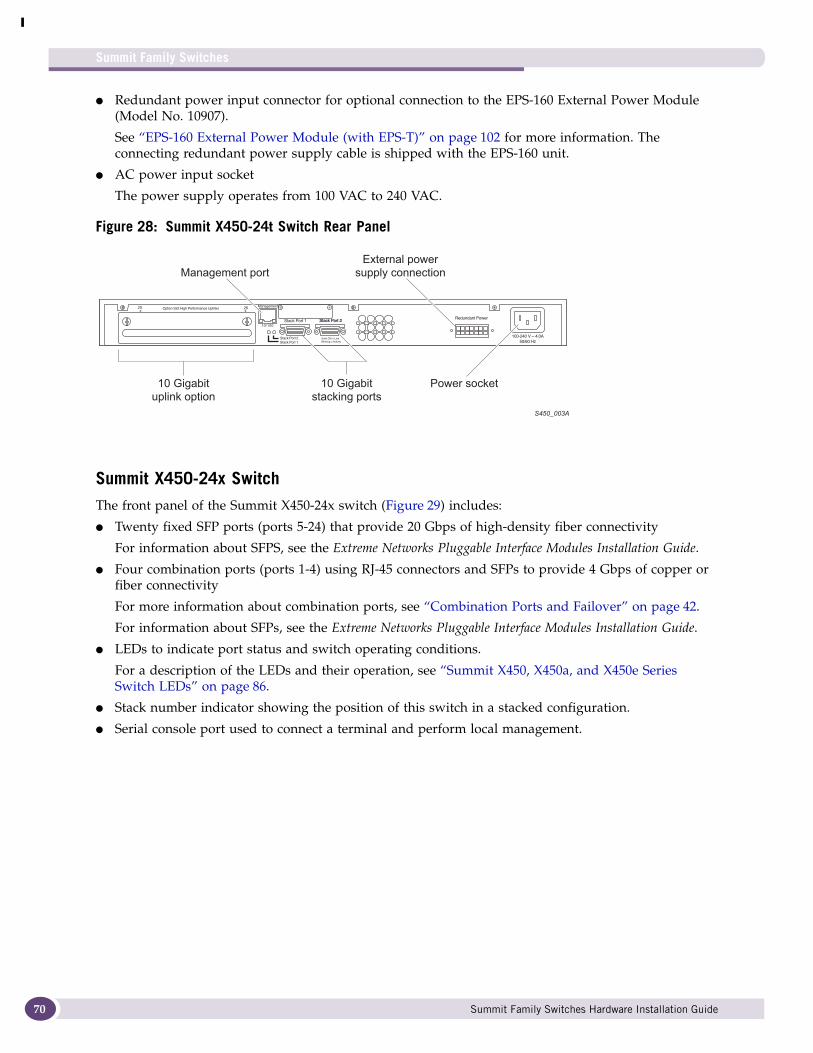
Summit Family Switches
70
● Redundant power input connector for optional connection to the EPS-160 External Power Module (Model No. 10907).
See “EPS-160 External Power Module (with EPS-T)” on page 102 for more information. The connecting redundant power supply cable is shipped with the EPS-160 unit.
● AC power input socket
The power supply operates from 100 VAC to 240 VAC.
Figure 28: Summit X450-24t Switch Rear Panel
Summit X450-24x SwitchThe front panel of the Summit X450-24x switch (Figure 29) includes:
● Twenty fixed SFP ports (ports 5-24) that provide 20 Gbps of high-density fiber connectivity
For information about SFPS, see the Extreme Networks Pluggable Interface Modules Installation Guide.
● Four combination ports (ports 1-4) using RJ-45 connectors and SFPs to provide 4 Gbps of copper or fiber connectivity
For more information about combination ports, see “Combination Ports and Failover” on page 42.
For information about SFPs, see the Extreme Networks Pluggable Interface Modules Installation Guide.
● LEDs to indicate port status and switch operating conditions.
For a description of the LEDs and their operation, see “Summit X450, X450a, and X450e Series Switch LEDs” on page 86.
● Stack number indicator showing the position of this switch in a stacked configuration.
● Serial console port used to connect a terminal and perform local management.
S450_003A
10 Gigabit
uplink option
Management port
10 Gigabit
stacking ports
Power socket
External power
supply connection
Summit Family Switches Hardware Installation Guide
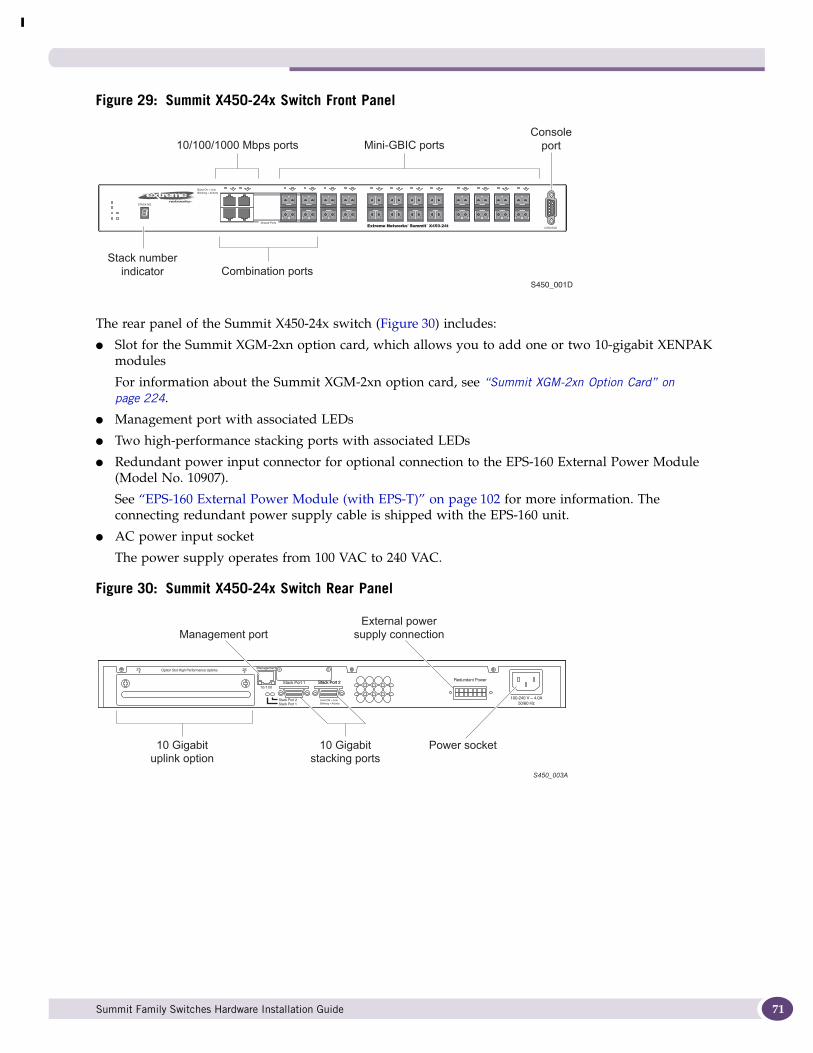
Figure 29: Summit X450-24x Switch Front Panel
The rear panel of the Summit X450-24x switch (Figure 30) includes:
● Slot for the Summit XGM-2xn option card, which allows you to add one or two 10-gigabit XENPAK modules
For information about the Summit XGM-2xn option card, see “Summit XGM-2xn Option Card” on page 224.
● Management port with associated LEDs
● Two high-performance stacking ports with associated LEDs
● Redundant power input connector for optional connection to the EPS-160 External Power Module (Model No. 10907).
See “EPS-160 External Power Module (with EPS-T)” on page 102 for more information. The connecting redundant power supply cable is shipped with the EPS-160 unit.
● AC power input socket
The power supply operates from 100 VAC to 240 VAC.
Figure 30: Summit X450-24x Switch Rear Panel
STACK NO.
Band On = LinkBlinking = Activity
Shared Ports
S450_001D
10/100/1000 Mbps portsConsole
portMini-GBIC ports
Combination portsStack number
indicator
S450_003A
10 Gigabit
uplink option
Management port
10 Gigabit
stacking ports
Power socket
External power
supply connection
Summit Family Switches Hardware Installation Guide 71
Summit Family Switches
72
Summit X450a Series SwitchesThe Summit X450a series switches are 24-port or 48-port switches without PoE options. The Ethernet ports are implemented as fixed 10/100/1000BASE-T RJ-45 ports or as installable SFP modules. These switches are available with either AC or DC internal power supplies. The switch automatically adjusts to the supply voltage. The internal AC power supply operates from 100 VAC to 240 VAC. The internal DC power supply operates from -36 VDC to -72 VDC.
The Summit X450a series switches include the following switches:
● Summit X450a-24t Switch
● Summit X450a-24t-TAA Switch
● Summit X450a-24tDC Switch
● Summit X450a-24tDC-TAA Switch
● Summit X450a-24x Switch
● Summit X450a-24x-TAA Switch
● Summit X450a-24xDC Switch
● Summit X450a-24xDC-TAA Switch
● Summit X450a-48t Switch
● Summit X450a-48t-TAA Switch
● Summit X450a-48tDC Switch
● Summit X450a-48tDC-TAA Switch
NOTE
In the descriptions that follow, references to a Summit X450a series model number also apply to the equivalent TAA-compliant switch version.
Summit X450a-24t SwitchThe front panel of the Summit X450a-24t switch (Figure 31) includes:
● Twenty fixed autosensing 10/100/1000 BASE-T ports (ports 1-20) that provide 20 Gbps of high-density copper connectivity
● Four combination ports (ports 21-24) using RJ-45 connectors and SFPs to provide 4 Gbps of copper or fiber connectivity
For more information about combination ports, see “Combination Ports and Failover” on page 42.
For information about SFPs, see the Extreme Networks Pluggable Interface Modules Installation Guide.
● LEDs to indicate port status and switch operating conditions.
For a description of the LEDs and their operation, see “Summit X450, X450a, and X450e Series Switch LEDs” on page 86.
● Stack number indicator showing the position of this switch in a stacked configuration.
● Serial console port used to connect a terminal and perform local management.
Summit Family Switches Hardware Installation Guide
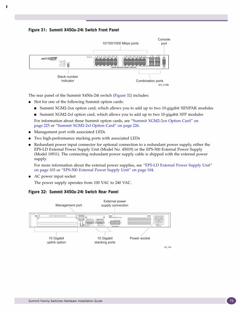
Figure 31: Summit X450a-24t Switch Front Panel
The rear panel of the Summit X450a-24t switch (Figure 32) includes:
● Slot for one of the following Summit option cards:
■ Summit XGM2-2xn option card, which allows you to add up to two 10-gigabit XENPAK modules
■ Summit XGM2-2xf option card, which allows you to add up to two 10-gigabit XFP modules
For information about these Summit option cards, see “Summit XGM2-2xn Option Card” on page 225 or “Summit XGM2-2xf Option Card” on page 226.
● Management port with associated LEDs
● Two high-performance stacking ports with associated LEDs
● Redundant power input connector for optional connection to a redundant power supply, either the EPS-LD External Power Supply Unit (Model No. 45019) or the EPS-500 External Power Supply (Model 10911). The connecting redundant power supply cable is shipped with the external power supply.
For more information about the external power supplies, see “EPS-LD External Power Supply Unit” on page 103 or “EPS-500 External Power Supply Unit” on page 104.
● AC power input socket
The power supply operates from 100 VAC to 240 VAC.
Figure 32: Summit X450a-24t Switch Rear Panel
SH_018B
10/100/1000 Mbps portsConsole
port
Combination portsStack number
indicator
SH_028
10 Gigabituplink option
Management port
10 Gigabitstacking ports
Power socket
External powersupply connection
Summit Family Switches Hardware Installation Guide 73
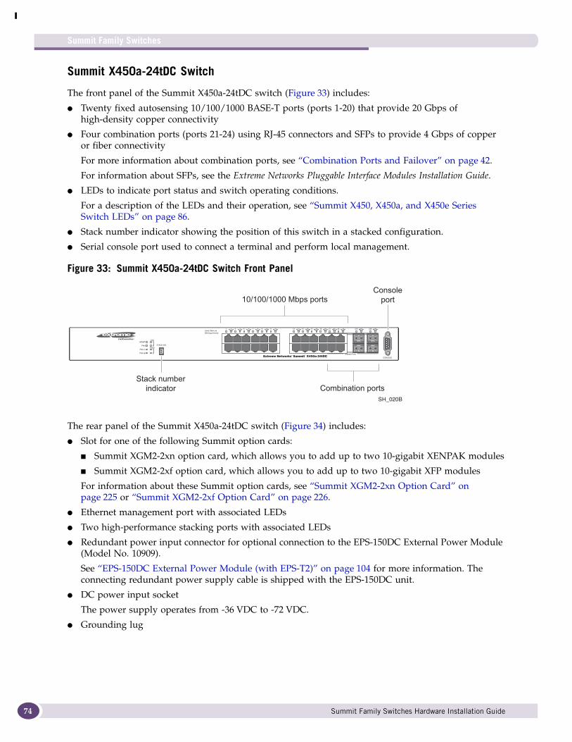
Summit Family Switches
74
Summit X450a-24tDC Switch
The front panel of the Summit X450a-24tDC switch (Figure 33) includes:
● Twenty fixed autosensing 10/100/1000 BASE-T ports (ports 1-20) that provide 20 Gbps of high-density copper connectivity
● Four combination ports (ports 21-24) using RJ-45 connectors and SFPs to provide 4 Gbps of copper or fiber connectivity
For more information about combination ports, see “Combination Ports and Failover” on page 42.
For information about SFPs, see the Extreme Networks Pluggable Interface Modules Installation Guide.
● LEDs to indicate port status and switch operating conditions.
For a description of the LEDs and their operation, see “Summit X450, X450a, and X450e Series Switch LEDs” on page 86.
● Stack number indicator showing the position of this switch in a stacked configuration.
● Serial console port used to connect a terminal and perform local management.
Figure 33: Summit X450a-24tDC Switch Front Panel
The rear panel of the Summit X450a-24tDC switch (Figure 34) includes:
● Slot for one of the following Summit option cards:
■ Summit XGM2-2xn option card, which allows you to add up to two 10-gigabit XENPAK modules
■ Summit XGM2-2xf option card, which allows you to add up to two 10-gigabit XFP modules
For information about these Summit option cards, see “Summit XGM2-2xn Option Card” on page 225 or “Summit XGM2-2xf Option Card” on page 226.
● Ethernet management port with associated LEDs
● Two high-performance stacking ports with associated LEDs
● Redundant power input connector for optional connection to the EPS-150DC External Power Module (Model No. 10909).
See “EPS-150DC External Power Module (with EPS-T2)” on page 104 for more information. The connecting redundant power supply cable is shipped with the EPS-150DC unit.
● DC power input socket
The power supply operates from -36 VDC to -72 VDC.
● Grounding lug
STACK NO.
Solid ON=LinkBlinking=Activity
MGMT
FAN
PSU-1
PSU-E
110G
Stack2
1
2
21 43 65 87 109 1211 1413 1615 1817 2019 2221 2423 22X21X 24X23X
Shared Ports
SH_020B
10/100/1000 Mbps portsConsole
port
Combination portsStack number
indicator
Summit Family Switches Hardware Installation Guide
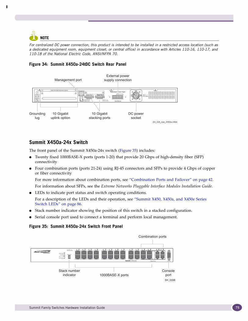
NOTE
For centralized DC power connection, this product is intended to be installed in a restricted access location (such as a dedicated equipment room, equipment closet, or central office) in accordance with Articles 110-16, 110-17, and 110-18 of the National Electric Code, ANSI/NFPA 70.
Figure 34: Summit X450a-24tDC Switch Rear Panel
Summit X450a-24x SwitchThe front panel of the Summit X450a-24x switch (Figure 35) includes:
● Twenty fixed 1000BASE-X ports (ports 1-20) that provide 20 Gbps of high-density fiber (SFP) connectivity
● Four combination ports (ports 21-24) using RJ-45 connectors and SFPs to provide 4 Gbps of copper or fiber connectivity
For more information about combination ports, see “Combination Ports and Failover” on page 42.
For information about SFPs, see the Extreme Networks Pluggable Interface Modules Installation Guide.
● LEDs to indicate port status and switch operating conditions.
For a description of the LEDs and their operation, see “Summit X450, X450a, and X450e Series Switch LEDs” on page 86.
● Stack number indicator showing the position of this switch in a stacked configuration.
● Serial console port used to connect a terminal and perform local management.
Figure 35: Summit X450a-24x Switch Front Panel
-48 V2.0 A Max
10 Gigabituplink option
Management port
10 Gigabitstacking ports
DC powersocket
External powersupply connection
Groundinglug
SH_026_rear_X450a-24tdc
STACK NO.
Solid ON = LinkBlinking = Activity
10GMGMT
FAN
PSU-1
PSU-E
1
2
Stack1
2
21 43 65 87 109 1211 1413 1615 1817 2019 2221 2423 22X21X 24X23X
SH_033B
1000BASE-X ports
Combination ports
Consoleport
Stack numberindicator
Summit Family Switches Hardware Installation Guide 75
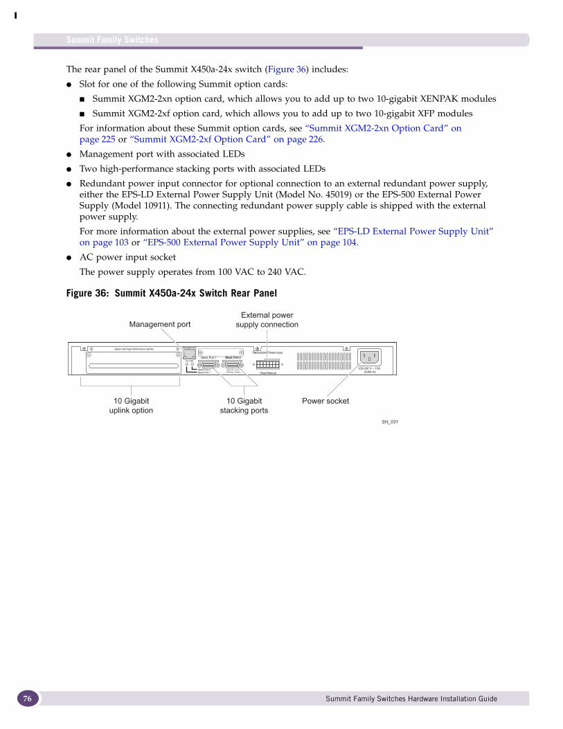
Summit Family Switches
76
The rear panel of the Summit X450a-24x switch (Figure 36) includes:
● Slot for one of the following Summit option cards:
■ Summit XGM2-2xn option card, which allows you to add up to two 10-gigabit XENPAK modules
■ Summit XGM2-2xf option card, which allows you to add up to two 10-gigabit XFP modules
For information about these Summit option cards, see “Summit XGM2-2xn Option Card” on page 225 or “Summit XGM2-2xf Option Card” on page 226.
● Management port with associated LEDs
● Two high-performance stacking ports with associated LEDs
● Redundant power input connector for optional connection to an external redundant power supply, either the EPS-LD External Power Supply Unit (Model No. 45019) or the EPS-500 External Power Supply (Model 10911). The connecting redundant power supply cable is shipped with the external power supply.
For more information about the external power supplies, see “EPS-LD External Power Supply Unit” on page 103 or “EPS-500 External Power Supply Unit” on page 104.
● AC power input socket
The power supply operates from 100 VAC to 240 VAC.
Figure 36: Summit X450a-24x Switch Rear Panel
SH_031
10 Gigabituplink option
Management port
10 Gigabitstacking ports
Power socket
External powersupply connection
Summit Family Switches Hardware Installation Guide
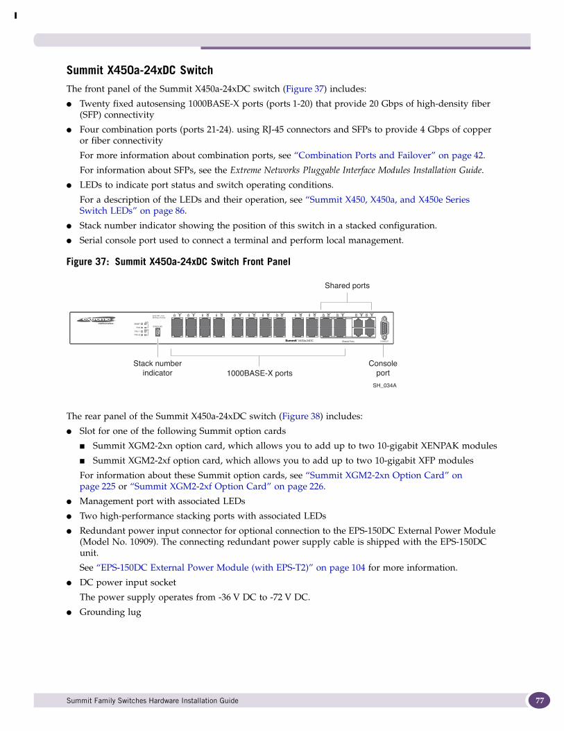
Summit X450a-24xDC SwitchThe front panel of the Summit X450a-24xDC switch (Figure 37) includes:
● Twenty fixed autosensing 1000BASE-X ports (ports 1-20) that provide 20 Gbps of high-density fiber (SFP) connectivity
● Four combination ports (ports 21-24). using RJ-45 connectors and SFPs to provide 4 Gbps of copper or fiber connectivity
For more information about combination ports, see “Combination Ports and Failover” on page 42.
For information about SFPs, see the Extreme Networks Pluggable Interface Modules Installation Guide.
● LEDs to indicate port status and switch operating conditions.
For a description of the LEDs and their operation, see “Summit X450, X450a, and X450e Series Switch LEDs” on page 86.
● Stack number indicator showing the position of this switch in a stacked configuration.
● Serial console port used to connect a terminal and perform local management.
Figure 37: Summit X450a-24xDC Switch Front Panel
The rear panel of the Summit X450a-24xDC switch (Figure 38) includes:
● Slot for one of the following Summit option cards
■ Summit XGM2-2xn option card, which allows you to add up to two 10-gigabit XENPAK modules
■ Summit XGM2-2xf option card, which allows you to add up to two 10-gigabit XFP modules
For information about these Summit option cards, see “Summit XGM2-2xn Option Card” on page 225 or “Summit XGM2-2xf Option Card” on page 226.
● Management port with associated LEDs
● Two high-performance stacking ports with associated LEDs
● Redundant power input connector for optional connection to the EPS-150DC External Power Module (Model No. 10909). The connecting redundant power supply cable is shipped with the EPS-150DC unit.
See “EPS-150DC External Power Module (with EPS-T2)” on page 104 for more information.
● DC power input socket
The power supply operates from -36 V DC to -72 V DC.
● Grounding lug
STACK NO.
Solid ON = LinkBlinking = Activity
10GMGMT
FAN
PSU-1
PSU-E
1
2
Stack1
2
21 43 65 87 109 1211 1413 1615 1817 2019 2221 2423 22X21X 24X23X
SH_034A
1000BASE-X ports
Shared ports
ConsoleStack numberindicator port
Summit Family Switches Hardware Installation Guide 77

Summit Family Switches
78
NOTE
For centralized DC power connection, this product is intended to be installed in a restricted access location (such as a dedicated equipment room, equipment closet, or central office) in accordance with Articles 110-16, 110-17, and 110-18 of the National Electric Code, ANSI/NFPA 70.
Figure 38: Summit X450a-24xDC Switch Rear Panel
Summit X450a-48t SwitchThe front panel of the Summit X450a-48t switch (Figure 39) includes:
● Forty-four fixed autosensing 10/100/1000 BASE-T ports (ports 1-44) that provide 44 Gbps of high-density copper connectivity
● Four combination ports (ports 45-48) using RJ-45 connectors and SFPs to provide 4 Gbps of fiber or copper connectivity
For more information about combination ports, see “Combination Ports and Failover” on page 42.
For information about SFPs, see the Extreme Networks Pluggable Interface Modules Installation Guide.
● LEDs to indicate port status and switch operating conditions.
For a description of the LEDs and their operation, see “Summit X450, X450a, and X450e Series Switch LEDs” on page 86.
● Stack number indicator showing the position of this switch in a stacked configuration.
● Serial console port used to connect a terminal and perform local management.
Figure 39: Summit X450a-48t Switch Front Panel
-48 V2.5 A Max
10 Gigabituplink option
Management port
10 Gigabitstacking ports
DC powersocket
External powersupply connection
Groundinglug
SH_032_X450a-24xdc
STACK NO.
Stack 10G
MGMT
FAN
PSU-1
PSU-E
Band On = LinkBlinking = Activity
21
12
12
43 65 87 109 1211 1413 1615 1817 2019 2221 2423 2625 2827 3029 3231 3433 3635 3837 4039 4241 4443 4645 4847 46X45X 48X47X
Shared Ports
SH_016C
Combination ports
Summit Family Switches Hardware Installation Guide
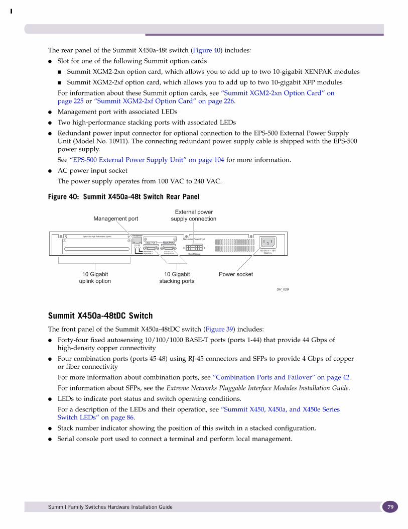
The rear panel of the Summit X450a-48t switch (Figure 40) includes:
● Slot for one of the following Summit option cards
■ Summit XGM2-2xn option card, which allows you to add up to two 10-gigabit XENPAK modules
■ Summit XGM2-2xf option card, which allows you to add up to two 10-gigabit XFP modules
For information about these Summit option cards, see “Summit XGM2-2xn Option Card” on page 225 or “Summit XGM2-2xf Option Card” on page 226.
● Management port with associated LEDs
● Two high-performance stacking ports with associated LEDs
● Redundant power input connector for optional connection to the EPS-500 External Power Supply Unit (Model No. 10911). The connecting redundant power supply cable is shipped with the EPS-500 power supply.
See “EPS-500 External Power Supply Unit” on page 104 for more information.
● AC power input socket
The power supply operates from 100 VAC to 240 VAC.
Figure 40: Summit X450a-48t Switch Rear Panel
Summit X450a-48tDC SwitchThe front panel of the Summit X450a-48tDC switch (Figure 39) includes:
● Forty-four fixed autosensing 10/100/1000 BASE-T ports (ports 1-44) that provide 44 Gbps of high-density copper connectivity
● Four combination ports (ports 45-48) using RJ-45 connectors and SFPs to provide 4 Gbps of copper or fiber connectivity
For more information about combination ports, see “Combination Ports and Failover” on page 42.
For information about SFPs, see the Extreme Networks Pluggable Interface Modules Installation Guide.
● LEDs to indicate port status and switch operating conditions.
For a description of the LEDs and their operation, see “Summit X450, X450a, and X450e Series Switch LEDs” on page 86.
● Stack number indicator showing the position of this switch in a stacked configuration.
● Serial console port used to connect a terminal and perform local management.
SH_029
10 Gigabituplink option
Management port
10 Gigabitstacking ports
Power socket
External powersupply connection
Summit Family Switches Hardware Installation Guide 79
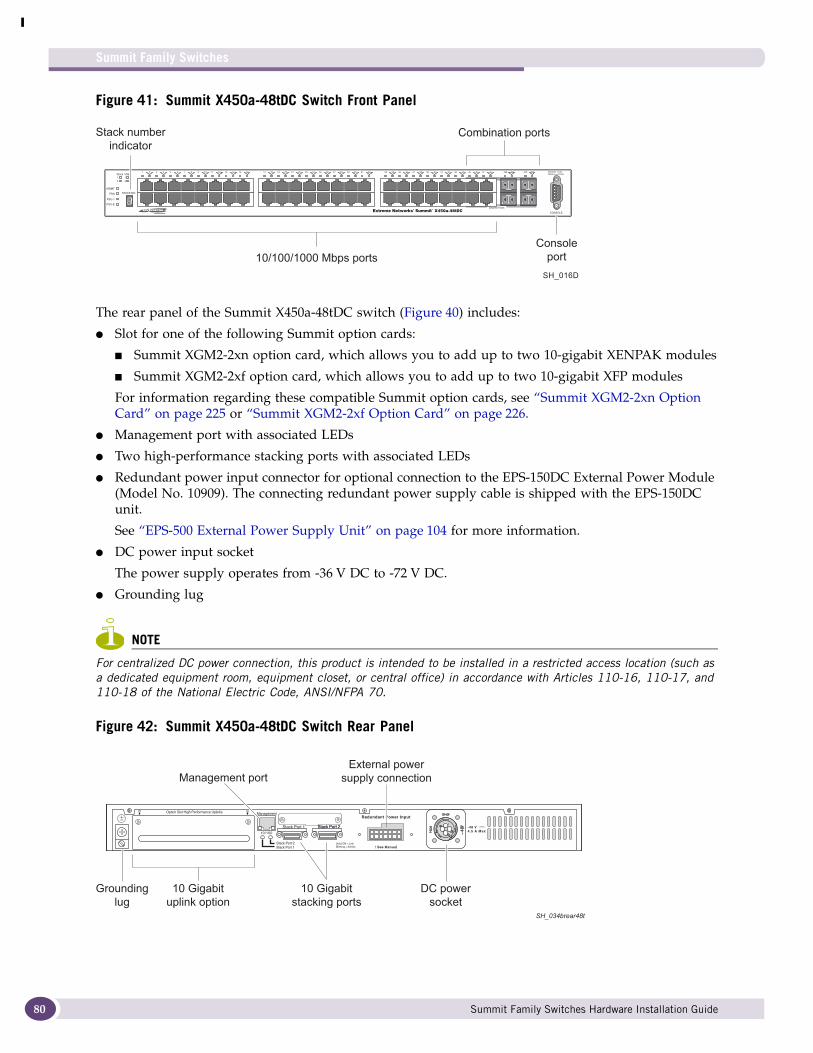
Summit Family Switches
80
Figure 41: Summit X450a-48tDC Switch Front Panel
The rear panel of the Summit X450a-48tDC switch (Figure 40) includes:
● Slot for one of the following Summit option cards:
■ Summit XGM2-2xn option card, which allows you to add up to two 10-gigabit XENPAK modules
■ Summit XGM2-2xf option card, which allows you to add up to two 10-gigabit XFP modules
For information regarding these compatible Summit option cards, see “Summit XGM2-2xn Option Card” on page 225 or “Summit XGM2-2xf Option Card” on page 226.
● Management port with associated LEDs
● Two high-performance stacking ports with associated LEDs
● Redundant power input connector for optional connection to the EPS-150DC External Power Module (Model No. 10909). The connecting redundant power supply cable is shipped with the EPS-150DC unit.
See “EPS-500 External Power Supply Unit” on page 104 for more information.
● DC power input socket
The power supply operates from -36 V DC to -72 V DC.
● Grounding lug
NOTE
For centralized DC power connection, this product is intended to be installed in a restricted access location (such as a dedicated equipment room, equipment closet, or central office) in accordance with Articles 110-16, 110-17, and 110-18 of the National Electric Code, ANSI/NFPA 70.
Figure 42: Summit X450a-48tDC Switch Rear Panel
STACK NO.
Stack 10G
MGMT
FAN
PSU-1
PSU-E
Band On = LinkBlinking = Activity
21
12
12
43 65 87 109 1211 1413 1615 1817 2019 2221 2423 2625 2827 3029 3231 3433 3635 3837 4039 4241 4443 4645 4847 46X45X 48X47X
Shared Ports
SH_016D
Stack numberindicator
Combination ports
-48 V4.5 A Max
10 Gigabituplink option
Management port
10 Gigabitstacking ports
DC powersocket
External powersupply connection
Groundinglug
SH_034brear48t
Summit Family Switches Hardware Installation Guide
Summit X450e Series SwitchesThe Summit X450e series switches are 24-port or 48-port PoE-capable switches. The Ethernet ports are implemented as fixed 10/100/1000BASE-T RJ-45 ports. These switches are available only with AC internal power supplies.
The Summit X450e series of switches consists of the following switches:
● Summit X450e-24p Switch
● Summit X450e-24p-TAA Switch
● Summit X450e-48p Switch
● Summit X450e-48p-TAA Switch
NOTE
In the descriptions that follow, references to a Summit X450e series model number also apply to the equivalent TAA-compliant switch version.
Summit X450e-24p SwitchThe front panel of the Summit X450e-24p switch (Figure 43) includes:
● Twenty fixed autosensing 10/100/1000 BASE-T PoE ports (ports 1-20) that provide high-density copper connectivity and a full 15.4 Watts of PoE per port
● Four combination ports (ports 21-24) using RJ-45 connectors and SFPs to provide 4 Gbps of copper or fiber connectivity
For more information about combination ports, see “Combination Ports and Failover” on page 42.
For information about SFPs, see the Extreme Networks Pluggable Interface Modules Installation Guide.
NOTE
All 24 ports can provide PoE power.
● LEDs to indicate port status and switch operating conditions.
For a description of the LEDs and their operation, see “Summit X450, X450a, and X450e Series Switch LEDs” on page 86.
● Stack number indicator showing the position of this switch in a stacked configuration.
● Serial console port used to connect a terminal and perform local management.
Summit Family Switches Hardware Installation Guide 81
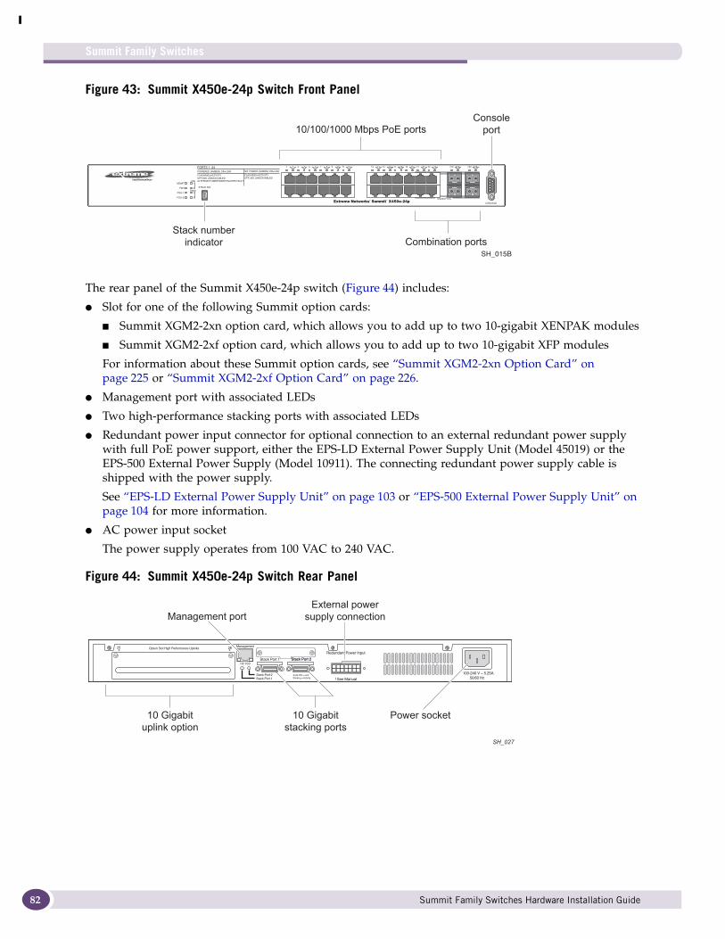
Summit Family Switches
82
Figure 43: Summit X450e-24p Switch Front Panel
The rear panel of the Summit X450e-24p switch (Figure 44) includes:
● Slot for one of the following Summit option cards:
■ Summit XGM2-2xn option card, which allows you to add up to two 10-gigabit XENPAK modules
■ Summit XGM2-2xf option card, which allows you to add up to two 10-gigabit XFP modules
For information about these Summit option cards, see “Summit XGM2-2xn Option Card” on page 225 or “Summit XGM2-2xf Option Card” on page 226.
● Management port with associated LEDs
● Two high-performance stacking ports with associated LEDs
● Redundant power input connector for optional connection to an external redundant power supply with full PoE power support, either the EPS-LD External Power Supply Unit (Model 45019) or the EPS-500 External Power Supply (Model 10911). The connecting redundant power supply cable is shipped with the power supply.
See “EPS-LD External Power Supply Unit” on page 103 or “EPS-500 External Power Supply Unit” on page 104 for more information.
● AC power input socket
The power supply operates from 100 VAC to 240 VAC.
Figure 44: Summit X450e-24p Switch Rear Panel
STACK NO.
PORTS 1 -24POWERED (AMBER) ON=LINK NO POWER (GREEN) ON=LINK
FLASHING=ACTIVITYOFF=NO LINK/DISABLEDALTERNATE AMBER/GREEN=PWR FAULT
FLASHING=ACTIVITYOFF=NO LINK/DISABLED
MGMT
FAN
PSU-1
PSU-E
110G
Stack2
1
2
21 43 65 87 109 1211 1413 1615 1817 2019 2221 2423 22X21X 24X23X
Shared Ports
SH_015B
10/100/1000 Mbps PoE portsConsole
port
Combination ports Stack number
indicator
SH_027
10 Gigabituplink option
Management port
10 Gigabitstacking ports
Power socket
External powersupply connection
Summit Family Switches Hardware Installation Guide
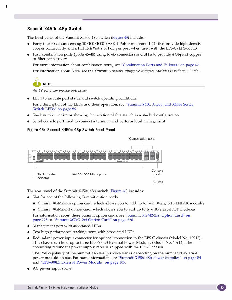
Summit X450e-48p Switch
The front panel of the Summit X450e-48p switch (Figure 45) includes:
● Forty-four fixed autosensing 10/100/1000 BASE-T PoE ports (ports 1-44) that provide high-density copper connectivity and a full 15.4 Watts of PoE per port when used with the EPS-C/EPS-600LS
● Four combination ports (ports 45-48) using RJ-45 connectors and SFPs to provide 4 Gbps of copper or fiber connectivity
For more information about combination ports, see “Combination Ports and Failover” on page 42.
For information about SFPs, see the Extreme Networks Pluggable Interface Modules Installation Guide.
NOTE
All 48 ports can provide PoE power
● LEDs to indicate port status and switch operating conditions.
For a description of the LEDs and their operation, see “Summit X450, X450a, and X450e Series Switch LEDs” on page 86.
● Stack number indicator showing the position of this switch in a stacked configuration.
● Serial console port used to connect a terminal and perform local management.
Figure 45: Summit X450e-48p Switch Front Panel
The rear panel of the Summit X450e-48p switch (Figure 46) includes:
● Slot for one of the following Summit option cards:
■ Summit XGM2-2xn option card, which allows you to add up to two 10-gigabit XENPAK modules
■ Summit XGM2-2xf option card, which allows you to add up to two 10-gigabit XFP modules
For information about these Summit option cards, see “Summit XGM2-2xn Option Card” on page 225 or “Summit XGM2-2xf Option Card” on page 226.
● Management port with associated LEDs
● Two high-performance stacking ports with associated LEDs
● Redundant power input connector for optional connection to the EPS-C chassis (Model No. 10912). This chassis can hold up to three EPS-600LS External Power Modules (Model No. 10913). The connecting redundant power supply cable is shipped with the EPS-C chassis.
The PoE capability of the Summit X450e-48p switch varies depending on the number of external power modules in use. For more information, see “Summit X450e-48p Power Supplies” on page 84 and “EPS-600LS External Power Module” on page 105.
● AC power input socket
STACK NO.
Stack 10G
MGMT
FAN
PSU-1
PSU-E
Solid ON = LinkBlinking = Activity
2112
12
43 65 87 109 1211 1413 1615 1817 2019 2221 2423 2625 2827 3029 3231 3433 3635 3837 4039 4241 4443 4645 4847 46X45X 48X47X
Shared Ports
SH_030B
Combination ports
Consoleport10/100/1000 Mbps portsStack number
indicator
Summit Family Switches Hardware Installation Guide 83

Summit Family Switches
84
The power supply operates from 100 VAC to 240 VAC.
Figure 46: Summit X450e-48p Switch Rear Panel
Summit X450e-48p Power SuppliesThe Summit X450e-48p switch is powered by both an internal power supply and an optional external redundant power supply system.
Internal Power Supply. The internal Summit X450e-48p power supply can provide 370 W of PoE power, as follows:
● In a 24 port configuration, it provides 15.4 W to each port.
● In 48-port configuration or any combination of ports where total PoE power does not exceed 370 watts, it provides 7.7 W to each port.
If the total system demands exceed this power limit, you can specify:
● Port priorities to identify which ports should be ranked higher when allocating power.
● Port disconnect precedence to specify the method of shutting off ports when not enough PoE power is available.
NOTE
For a detailed discussion of these concepts, see the Power over Ethernet section in the ExtremeXOS Concepts Guide.
External Power Supplies. The Summit X450e-48p switch can be powered by one, two, or three external power modules through the redundant power input connector on the rear of the switch.
The EPS-C (External Power Supply Chassis) is shipped with the redundant power supply cable that connects to the redundant input connector on the rear of the switch. The EPS-C chassis can hold from one to three 600-Watt EPS-600LS (external power module) units.
SH_033
10 Gigabituplink option
Management port
10 Gigabitstacking ports
Power socket
External powersupply connection
Summit Family Switches Hardware Installation Guide
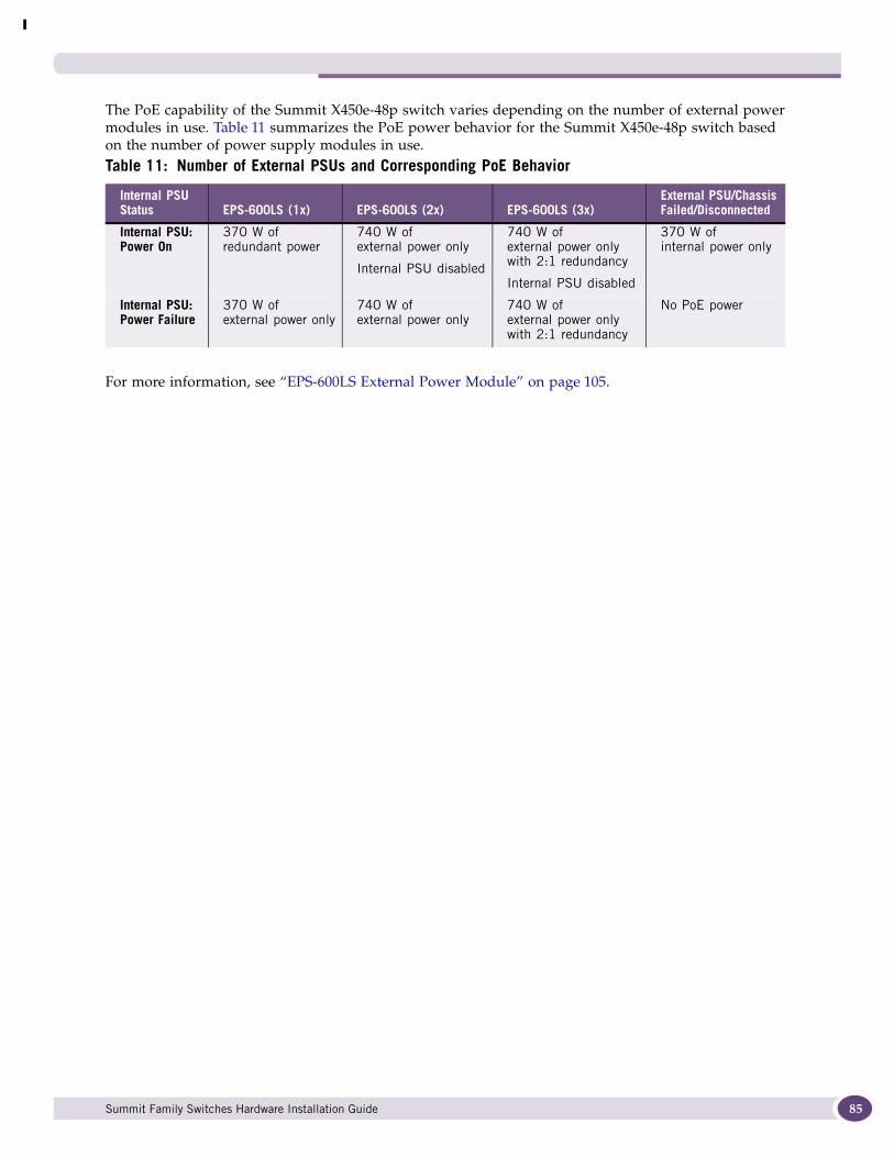
The PoE capability of the Summit X450e-48p switch varies depending on the number of external power modules in use. Table 11 summarizes the PoE power behavior for the Summit X450e-48p switch based on the number of power supply modules in use.
For more information, see “EPS-600LS External Power Module” on page 105.
Table 11: Number of External PSUs and Corresponding PoE Behavior
Internal PSU Status EPS-600LS (1x) EPS-600LS (2x) EPS-600LS (3x)
External PSU/Chassis Failed/Disconnected
Internal PSU: Power On
370 W of redundant power
740 W of external power only
Internal PSU disabled
740 W of external power only with 2:1 redundancy
Internal PSU disabled
370 W of internal power only
Internal PSU: Power Failure
370 W of external power only
740 W of external power only
740 W of external power only with 2:1 redundancy
No PoE power
Summit Family Switches Hardware Installation Guide 85

Summit Family Switches
86
Summit X450, X450a, and X450e Series Switch LEDsTable 12 describes the LEDs for the Summit X450, X450a, and X450e switches.
Table 12: LEDs on the Summit X450, X450a, and X450e Switches
Label or Type Color/State Meaning
Front PanelMGMT Blinking green (fast) Power-on self-test (POST) in progress.
Steady green POST passed. System is booting image.
Blinking green (slow) Normal operation
Blinking amber Switch diagnostics running.orSystem is disabled. POST failed or system overheated.
Off No external power attached
FAN Steady green Normal operation
Steady amber* A single fan in the array has failed. The switch can continue to operate indefinitely.*
Blinking amber FailureorTwo or more fans in the array have failed. Because system cooling is compromised, you should replace the switch.*
Off No power
* These states for the Fan LED occur only on Summit X450a-48tDC switches with a manufacturing part number of 800294-00 and X450a-48tDC-TAA switches with a manufacturing part number of 800337-00.
PSU-I (Internal power supply)
Steady green Normal operation
Blinking amber Failure
Off No power
PSU-E(External power supply)
Steady green Normal operation
Blinking amber Failure
Off No external power attached
Ethernet Ports1 – 24 or 1 – 48 (21 –24 and 45 – 48 are shared ports)
Steady green Link OK
Blinking green Activity
Off Link is not present or port is disabled.
Stack Number Indicator Top half of number blinking
This switch is the stack master.
Lower half of number blinking
This switch is the stack backup.
Number lights steadily This switch is a standby node (neither the master nor the backup).
LED dark This stackable switch is not in stacking mode.
Summit Family Switches Hardware Installation Guide
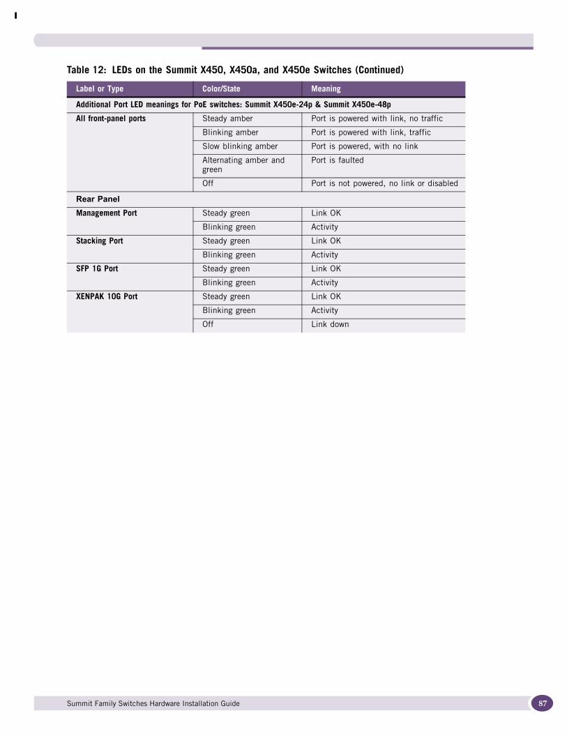
Additional Port LED meanings for PoE switches: Summit X450e-24p & Summit X450e-48p
All front-panel ports Steady amber Port is powered with link, no traffic
Blinking amber Port is powered with link, traffic
Slow blinking amber Port is powered, with no link
Alternating amber and green
Port is faulted
Off Port is not powered, no link or disabled
Rear PanelManagement Port Steady green Link OK
Blinking green Activity
Stacking Port Steady green Link OK
Blinking green Activity
SFP 1G Port Steady green Link OK
Blinking green Activity
XENPAK 10G Port Steady green Link OK
Blinking green Activity
Off Link down
Table 12: LEDs on the Summit X450, X450a, and X450e Switches (Continued)
Label or Type Color/State Meaning
Summit Family Switches Hardware Installation Guide 87
Summit Family Switches
88
Summit X480 Series SwitchesThe Summit X480 series switches are 24-port or 48-port switches that provide Ethernet connectivity using fixed 10/100/1000BASE-T RJ-45 ports, installable SFP optical modules, or installable XFP optical modules.
The Summit X480 series switches include the following base models:
● Summit X480-24x switch (see page 89)
● Summit X480-48x switch (see page 90)
● Summit X480-48t switch (see page 91)
A serial console port on the front panel of the Summit X480 series switch allows you to connect a terminal and perform local management. An Ethernet management port can be used to connect the system to a parallel management network for administration. Alternatively, you can use an Ethernet cable to connect this port directly to a laptop to view and locally manage the switch configuration. The Ethernet management port supports 10/100/1000 Mbps speeds.
The rear panel of the switch provides a slot for an installed option card called a versatile interface module or VIM. The types of VIM available for the Summit X480 series switches are:
● VIM2-SummitStack versatile interface module (see page 92)
Provides two 20-Gbps stacking ports
● VIM2-10G4X versatile interface module (see page 92)
Provides four 10-Gbps XFP ports
● VIM2-SummitStack128 versatile interface module (see page 93)
Provides two 64-Gbps stacking ports
NOTE
The Summit X480 switches are only compatible with VIM2 modules. Other VIM types that may appear to be mechanically compatible with the Summit X480 switches will not function if they are installed in these switches.
Cooling is provided by a replaceable fan module. Two power supply bays accommodate either AC or DC power supplies.
Summit Family Switches Hardware Installation Guide
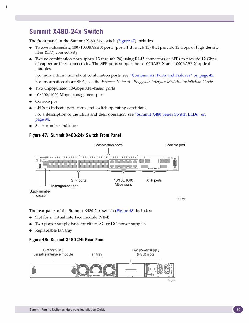
Summit X480-24x SwitchThe front panel of the Summit X480-24x switch (Figure 47) includes:
● Twelve autosensing 100/1000BASE-X ports (ports 1 through 12) that provide 12 Gbps of high-density fiber (SFP) connectivity
● Twelve combination ports (ports 13 through 24) using RJ-45 connectors or SFPs to provide 12 Gbps of copper or fiber connectivity. The SFP ports support both 100BASE-X and 1000BASE-X optical modules.
For more information about combination ports, see “Combination Ports and Failover” on page 42.
For information about SFPs, see the Extreme Networks Pluggable Interface Modules Installation Guide.
● Two unpopulated 10-Gbps XFP-based ports
● 10/100/1000 Mbps management port
● Console port
● LEDs to indicate port status and switch operating conditions.
For a description of the LEDs and their operation, see “Summit X480 Series Switch LEDs” on page 94.
● Stack number indicator
Figure 47: Summit X480-24x Switch Front Panel
The rear panel of the Summit X480-24x switch (Figure 48) includes:
● Slot for a virtual interface module (VIM)
● Two power supply bays for either AC or DC power supplies
● Replaceable fan tray
Figure 48: Summit X480-24t Rear Panel
Stack numberindicator
XFP ports
Management port
Combination ports
SFP ports 10/100/1000Mbps ports
Console port
SH_120
Slot for VIM2versatile interface module Fan tray
Two power supply(PSU) slots
SH_154
Summit Family Switches Hardware Installation Guide 89
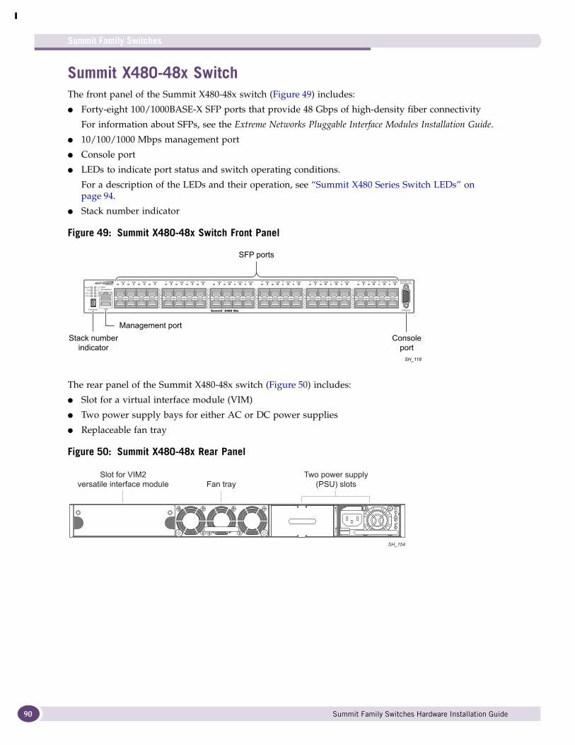
Summit Family Switches
90
Summit X480-48x SwitchThe front panel of the Summit X480-48x switch (Figure 49) includes:
● Forty-eight 100/1000BASE-X SFP ports that provide 48 Gbps of high-density fiber connectivity
For information about SFPs, see the Extreme Networks Pluggable Interface Modules Installation Guide.
● 10/100/1000 Mbps management port
● Console port
● LEDs to indicate port status and switch operating conditions.
For a description of the LEDs and their operation, see “Summit X480 Series Switch LEDs” on page 94.
● Stack number indicator
Figure 49: Summit X480-48x Switch Front Panel
The rear panel of the Summit X480-48x switch (Figure 50) includes:
● Slot for a virtual interface module (VIM)
● Two power supply bays for either AC or DC power supplies
● Replaceable fan tray
Figure 50: Summit X480-48x Rear Panel
Stack numberindicator
Management port
SFP ports
ConsoleportSH_118
Slot for VIM2versatile interface module Fan tray
Two power supply(PSU) slots
SH_154
Summit Family Switches Hardware Installation Guide
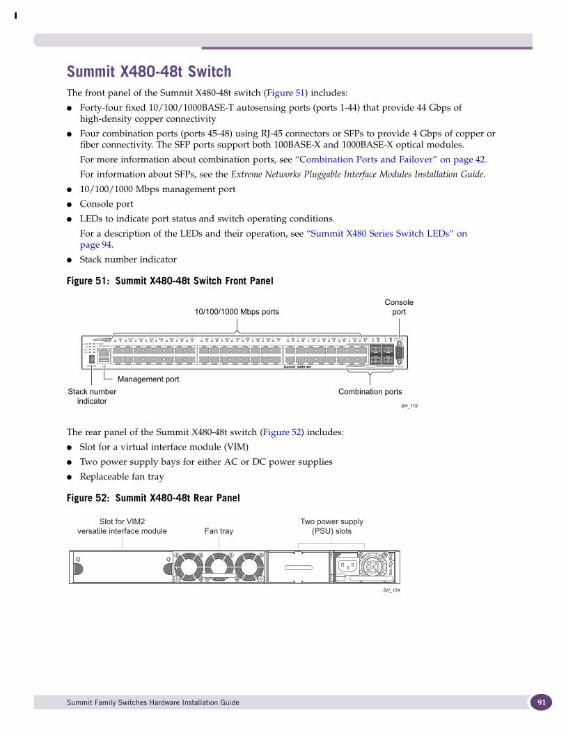
Summit X480-48t SwitchThe front panel of the Summit X480-48t switch (Figure 51) includes:
● Forty-four fixed 10/100/1000BASE-T autosensing ports (ports 1-44) that provide 44 Gbps of high-density copper connectivity
● Four combination ports (ports 45-48) using RJ-45 connectors or SFPs to provide 4 Gbps of copper or fiber connectivity. The SFP ports support both 100BASE-X and 1000BASE-X optical modules.
For more information about combination ports, see “Combination Ports and Failover” on page 42.
For information about SFPs, see the Extreme Networks Pluggable Interface Modules Installation Guide.
● 10/100/1000 Mbps management port
● Console port
● LEDs to indicate port status and switch operating conditions.
For a description of the LEDs and their operation, see “Summit X480 Series Switch LEDs” on page 94.
● Stack number indicator
Figure 51: Summit X480-48t Switch Front Panel
The rear panel of the Summit X480-48t switch (Figure 52) includes:
● Slot for a virtual interface module (VIM)
● Two power supply bays for either AC or DC power supplies
● Replaceable fan tray
Figure 52: Summit X480-48t Rear Panel
Stack numberindicator
Combination ports
Management port
10/100/1000 Mbps portsConsole
port
SH_119
Slot for VIM2versatile interface module Fan tray
Two power supply(PSU) slots
SH_154
Summit Family Switches Hardware Installation Guide 91
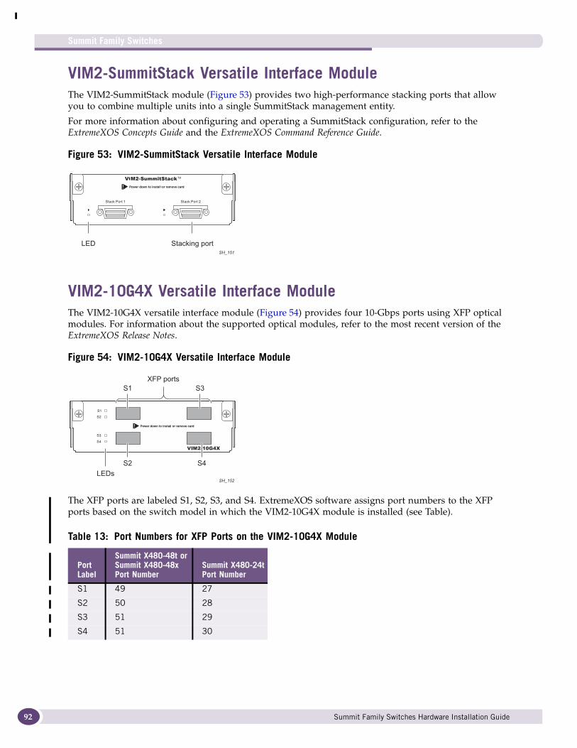
Summit Family Switches
92
VIM2-SummitStack Versatile Interface ModuleThe VIM2-SummitStack module (Figure 53) provides two high-performance stacking ports that allow you to combine multiple units into a single SummitStack management entity.
For more information about configuring and operating a SummitStack configuration, refer to the ExtremeXOS Concepts Guide and the ExtremeXOS Command Reference Guide.
Figure 53: VIM2-SummitStack Versatile Interface Module
VIM2-10G4X Versatile Interface ModuleThe VIM2-10G4X versatile interface module (Figure 54) provides four 10-Gbps ports using XFP optical modules. For information about the supported optical modules, refer to the most recent version of the ExtremeXOS Release Notes.
Figure 54: VIM2-10G4X Versatile Interface Module
The XFP ports are labeled S1, S2, S3, and S4. ExtremeXOS software assigns port numbers to the XFP ports based on the switch model in which the VIM2-10G4X module is installed (see Table).
Table 13: Port Numbers for XFP Ports on the VIM2-10G4X Module
Port Label
Summit X480-48t orSummit X480-48xPort Number
Summit X480-24tPort Number
S1 49 27
S2 50 28
S3 51 29
S4 51 30
LED Stacking portSH_151
LEDs
S2
S1 S3
S4
XFP ports
SH_152
Summit Family Switches Hardware Installation Guide
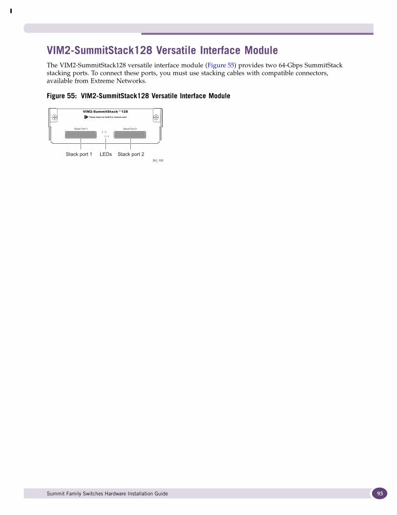
VIM2-SummitStack128 Versatile Interface ModuleThe VIM2-SummitStack128 versatile interface module (Figure 55) provides two 64-Gbps SummitStack stacking ports. To connect these ports, you must use stacking cables with compatible connectors, available from Extreme Networks.
Figure 55: VIM2-SummitStack128 Versatile Interface Module
LEDsStack port 1 Stack port 2SH_153
Summit Family Switches Hardware Installation Guide 93
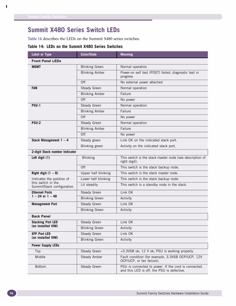
Summit Family Switches
94
Summit X480 Series Switch LEDsTable 14 describes the LEDs on the Summit X480 series switches.
Table 14: LEDs on the Summit X480 Series Switches
Label or Type Color/State Meaning
Front Panel LEDsMGMT Blinking Green Normal operation
Blinking Amber Power-on self test (POST) failed; diagnostic test in progress
Off No external power attached
FAN Steady Green Normal operation
Blinking Amber Failure
Off No power
PSU-1 Steady Green Normal operation
Blinking Amber Failure
Off No power
PSU-2 Steady Green Normal operation
Blinking Amber Failure
Off No power
Stack Management 1 – 4 Steady green Link OK on the indicated stack port.
Blinking green Activity on the indicated stack port.
2-digit Stack number Indicator
Left digit (1) Blinking This switch is the stack master node (see description of right digit).
Off This switch is the stack backup node.
Right digit (1 – 8)
Indicates the position of this switch in the SummitStack configuration.
Upper half blinking This switch is the stack master node.
Lower half blinking This switch is the stack backup node.
Lit steadily This switch is a standby node in the stack.
Ethernet Ports1 – 24 or 1 – 48
Steady Green Link OK
Blinking Green Activity
Management Port Steady Green Link OK
Blinking Green Activity
Back PanelStacking Port LED(on installed VIM)
Steady Green Link OK
Blinking Green Activity
XFP Port LED(on installed VIM)
Steady Green Link OK
Blinking Green Activity
Power Supply LEDs
Top Steady Green +3.3VSB ok; 12 V ok; PSU is working properly.
Middle Steady Amber Fault condition (for example, 3.3VSB OCP/UCP, 12V OCP/UCP, or fan failure).
Bottom Steady Green PSU is connected to power. If the cord is connected and this LED is off, the PSU is defective.
Summit Family Switches Hardware Installation Guide
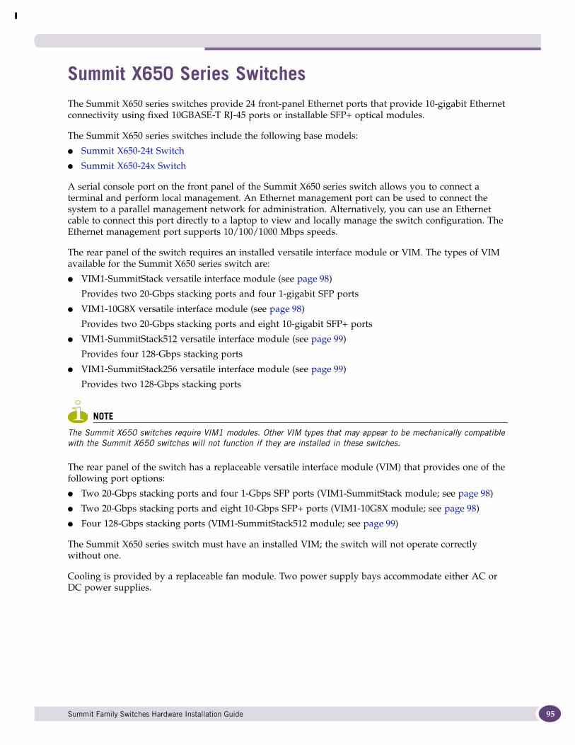
Summit X650 Series SwitchesThe Summit X650 series switches provide 24 front-panel Ethernet ports that provide 10-gigabit Ethernet connectivity using fixed 10GBASE-T RJ-45 ports or installable SFP+ optical modules.
The Summit X650 series switches include the following base models:
● Summit X650-24t Switch
● Summit X650-24x Switch
A serial console port on the front panel of the Summit X650 series switch allows you to connect a terminal and perform local management. An Ethernet management port can be used to connect the system to a parallel management network for administration. Alternatively, you can use an Ethernet cable to connect this port directly to a laptop to view and locally manage the switch configuration. The Ethernet management port supports 10/100/1000 Mbps speeds.
The rear panel of the switch requires an installed versatile interface module or VIM. The types of VIM available for the Summit X650 series switch are:
● VIM1-SummitStack versatile interface module (see page 98)
Provides two 20-Gbps stacking ports and four 1-gigabit SFP ports
● VIM1-10G8X versatile interface module (see page 98)
Provides two 20-Gbps stacking ports and eight 10-gigabit SFP+ ports
● VIM1-SummitStack512 versatile interface module (see page 99)
Provides four 128-Gbps stacking ports
● VIM1-SummitStack256 versatile interface module (see page 99)
Provides two 128-Gbps stacking ports
NOTE
The Summit X650 switches require VIM1 modules. Other VIM types that may appear to be mechanically compatible with the Summit X650 switches will not function if they are installed in these switches.
The rear panel of the switch has a replaceable versatile interface module (VIM) that provides one of the following port options:
● Two 20-Gbps stacking ports and four 1-Gbps SFP ports (VIM1-SummitStack module; see page 98)
● Two 20-Gbps stacking ports and eight 10-Gbps SFP+ ports (VIM1-10G8X module; see page 98)
● Four 128-Gbps stacking ports (VIM1-SummitStack512 module; see page 99)
The Summit X650 series switch must have an installed VIM; the switch will not operate correctly without one.
Cooling is provided by a replaceable fan module. Two power supply bays accommodate either AC or DC power supplies.
Summit Family Switches Hardware Installation Guide 95
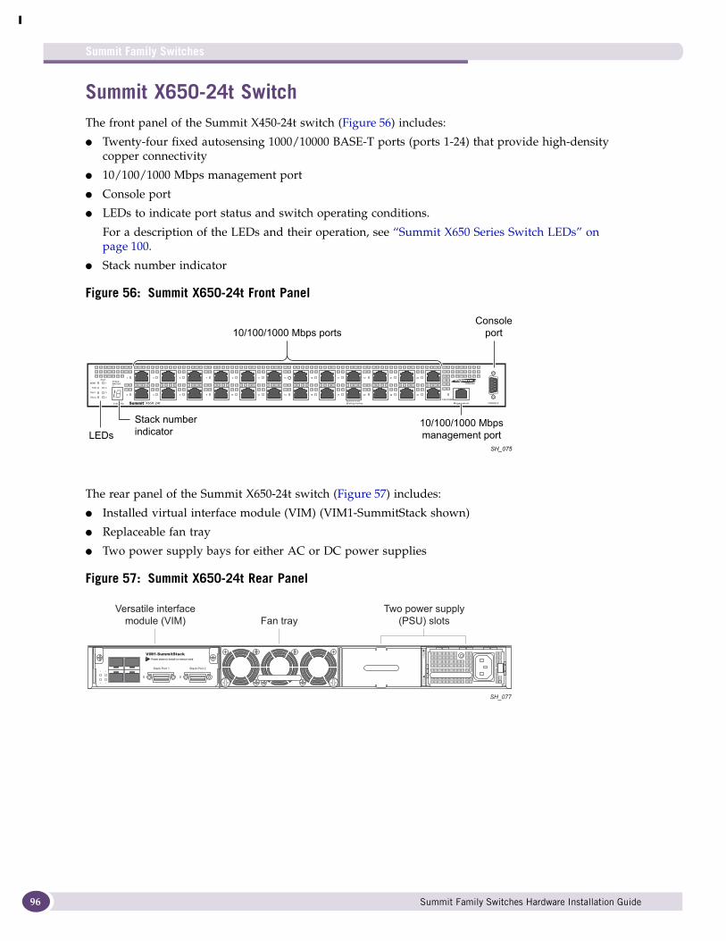
Summit Family Switches
96
Summit X650-24t SwitchThe front panel of the Summit X450-24t switch (Figure 56) includes:
● Twenty-four fixed autosensing 1000/10000 BASE-T ports (ports 1-24) that provide high-density copper connectivity
● 10/100/1000 Mbps management port
● Console port
● LEDs to indicate port status and switch operating conditions.
For a description of the LEDs and their operation, see “Summit X650 Series Switch LEDs” on page 100.
● Stack number indicator
Figure 56: Summit X650-24t Front Panel
The rear panel of the Summit X650-24t switch (Figure 57) includes:
● Installed virtual interface module (VIM) (VIM1-SummitStack shown)
● Replaceable fan tray
● Two power supply bays for either AC or DC power supplies
Figure 57: Summit X650-24t Rear Panel
LEDs10/100/1000 Mbpsmanagement port
Stack numberindicator
10/100/1000 Mbps portsConsole
port
SH_075
Versatile interfacemodule (VIM) Fan tray
Two power supply(PSU) slots
SH_077
Summit Family Switches Hardware Installation Guide
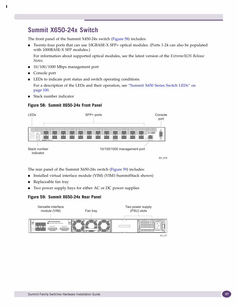
Summit X650-24x SwitchThe front panel of the Summit X450-24x switch (Figure 58) includes:
● Twenty-four ports that can use 10GBASE-X SFP+ optical modules. (Ports 1-24 can also be populated with 1000BASE-X SFP modules.)
For information about supported optical modules, see the latest version of the ExtremeXOS Release Notes.
● 10/100/1000 Mbps management port
● Console port
● LEDs to indicate port status and switch operating conditions.
For a description of the LEDs and their operation, see “Summit X650 Series Switch LEDs” on page 100.
● Stack number indicator
Figure 58: Summit X650-24x Front Panel
The rear panel of the Summit X650-24x switch (Figure 59) includes:
● Installed virtual interface module (VIM) (VIM1-SummitStack shown)
● Replaceable fan tray
● Two power supply bays for either AC or DC power supplies
Figure 59: Summit X650-24x Rear Panel
SH_076
SFP+ ports Consoleport
LEDs
Stack numberindicator
10/100/1000 management port
Versatile interfacemodule (VIM) Fan tray
Two power supply(PSU) slots
SH_077
Summit Family Switches Hardware Installation Guide 97
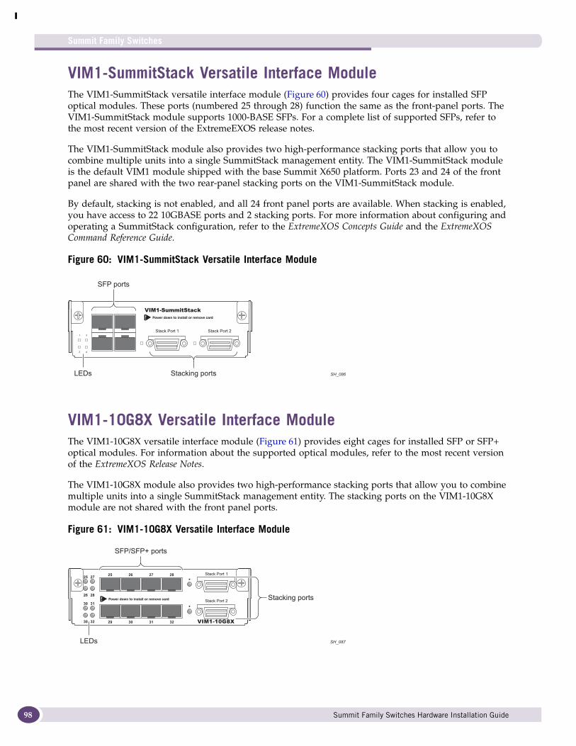
Summit Family Switches
98
VIM1-SummitStack Versatile Interface ModuleThe VIM1-SummitStack versatile interface module (Figure 60) provides four cages for installed SFP optical modules. These ports (numbered 25 through 28) function the same as the front-panel ports. The VIM1-SummitStack module supports 1000-BASE SFPs. For a complete list of supported SFPs, refer to the most recent version of the ExtremeEXOS release notes.
The VIM1-SummitStack module also provides two high-performance stacking ports that allow you to combine multiple units into a single SummitStack management entity. The VIM1-SummitStack module is the default VIM1 module shipped with the base Summit X650 platform. Ports 23 and 24 of the front panel are shared with the two rear-panel stacking ports on the VIM1-SummitStack module.
By default, stacking is not enabled, and all 24 front panel ports are available. When stacking is enabled, you have access to 22 10GBASE ports and 2 stacking ports. For more information about configuring and operating a SummitStack configuration, refer to the ExtremeXOS Concepts Guide and the ExtremeXOS Command Reference Guide.
Figure 60: VIM1-SummitStack Versatile Interface Module
VIM1-10G8X Versatile Interface ModuleThe VIM1-10G8X versatile interface module (Figure 61) provides eight cages for installed SFP or SFP+ optical modules. For information about the supported optical modules, refer to the most recent version of the ExtremeXOS Release Notes.
The VIM1-10G8X module also provides two high-performance stacking ports that allow you to combine multiple units into a single SummitStack management entity. The stacking ports on the VIM1-10G8X module are not shared with the front panel ports.
Figure 61: VIM1-10G8X Versatile Interface Module
SFP ports
LEDs Stacking ports SH_086
Stacking ports
SH_087
2525 27
26 28
30 31
30 32
26 27 28
29 30 31 32
LEDs
SFP/SFP+ ports
Summit Family Switches Hardware Installation Guide
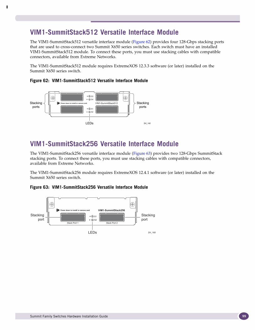
VIM1-SummitStack512 Versatile Interface ModuleThe VIM1-SummitStack512 versatile interface module (Figure 62) provides four 128-Gbps stacking ports that are used to cross-connect two Summit X650 series switches. Each switch must have an installed VIM1-SummitStack512 module. To connect these ports, you must use stacking cables with compatible connectors, available from Extreme Networks.
The VIM1-SummitStack512 module requires ExtremeXOS 12.3.3 software (or later) installed on the Summit X650 series switch.
Figure 62: VIM1-SummitStack512 Versatile Interface Module
VIM1-SummitStack256 Versatile Interface ModuleThe VIM1-SummitStack256 versatile interface module (Figure 63) provides two 128-Gbps SummitStack stacking ports. To connect these ports, you must use stacking cables with compatible connectors, available from Extreme Networks.
The VIM1-SummitStack256 module requires ExtremeXOS 12.4.1 software (or later) installed on the Summit X650 series switch.
Figure 63: VIM1-SummitStack256 Versatile Interface Module
Stackingports
Stackingports
SH_140LEDs
Stackingport
Stackingport
SH_168LEDs
Summit Family Switches Hardware Installation Guide 99
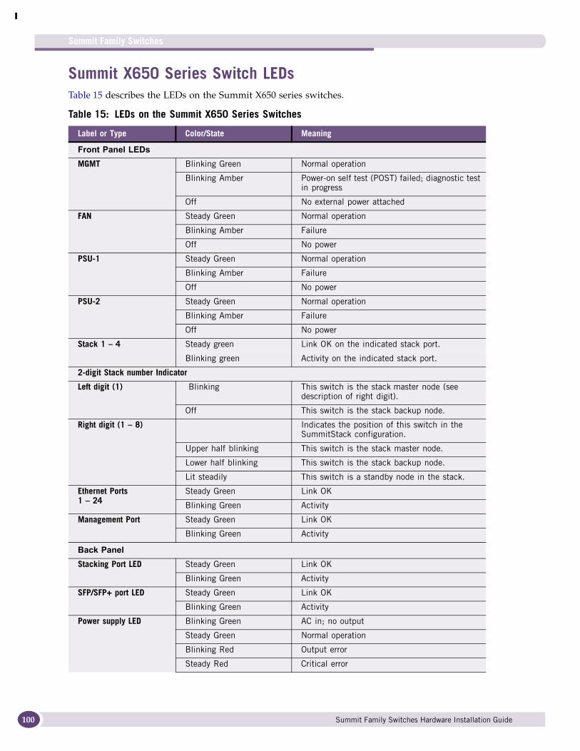
Summit Family Switches
100
Summit X650 Series Switch LEDsTable 15 describes the LEDs on the Summit X650 series switches.
Table 15: LEDs on the Summit X650 Series Switches
Label or Type Color/State Meaning
Front Panel LEDsMGMT Blinking Green Normal operation
Blinking Amber Power-on self test (POST) failed; diagnostic test in progress
Off No external power attached
FAN Steady Green Normal operation
Blinking Amber Failure
Off No power
PSU-1 Steady Green Normal operation
Blinking Amber Failure
Off No power
PSU-2 Steady Green Normal operation
Blinking Amber Failure
Off No power
Stack 1 – 4 Steady green Link OK on the indicated stack port.
Blinking green Activity on the indicated stack port.
2-digit Stack number Indicator
Left digit (1) Blinking This switch is the stack master node (see description of right digit).
Off This switch is the stack backup node.
Right digit (1 – 8) Indicates the position of this switch in the SummitStack configuration.
Upper half blinking This switch is the stack master node.
Lower half blinking This switch is the stack backup node.
Lit steadily This switch is a standby node in the stack.
Ethernet Ports1 – 24
Steady Green Link OK
Blinking Green Activity
Management Port Steady Green Link OK
Blinking Green Activity
Back PanelStacking Port LED Steady Green Link OK
Blinking Green Activity
SFP/SFP+ port LED Steady Green Link OK
Blinking Green Activity
Power supply LED Blinking Green AC in; no output
Steady Green Normal operation
Blinking Red Output error
Steady Red Critical error
Summit Family Switches Hardware Installation Guide

2 Summit Power Supplies
This chapter describes Extreme Networks power supplies available for use with the Summit family switches. The Summit X650 series switches have replaceable power supplies; redundant external power supplies are available for the other Summit series.
This chapter includes the following sections:
● Overview on page 101
● EPS-160 External Power Module (with EPS-T) on page 102
● EPS-LD External Power Supply Unit on page 103
● EPS-500 External Power Supply Unit on page 104
● EPS-150DC External Power Module (with EPS-T2) on page 104
● EPS-600LS External Power Module on page 105
● Summit X480 Power Supplies on page 107
● Summit X650 Power Supplies on page 108
OverviewSummit family switches are shipped with an internal power supply (replaceable on the Summit X650 series switches) that supplies all of the power needed for most switch operation. An optional redundant power supply can be added to most Summit models to protect against a power supply failure and to provide increased support for PoE operation on applicable switches.
Table 16 lists the Summit family switches and compatible external power supplies.
Table 16: Summit Switch and EPS Compatibility
Switch Model Compatible EPS Model Number
Summit X450 Series Switches
Summit X450-24t EPS-160 External Power Module with EPS-T EPS-160: 10907EPS-T: 10906
Summit X450-24x EPS-160 External Power Module with EPS-T EPS-160: 10907EPS-T: 10906
EPS-500 External Power Supply Unit 10911
Summit X450a Series Switches
Summit X450a-24t EPS-LD External Power Supply Unit 45019
EPS-500 External Power Supply Unit 10911
Summit X450a-24tDC EPS-150DC External Power Module with EPS-T2 EPS-150DC: 10909EPS-T2: 10910
Summit X450a-24x EPS-LD External Power Supply Unit 45019
EPS-500 External Power Supply Unit 10911
Summit X450a-24xDC EPS-150DC External Power Module with EPS-T2 EPS-150DC: 10909EPS-T2: 10910
Summit Family Switches Hardware Installation Guide 101
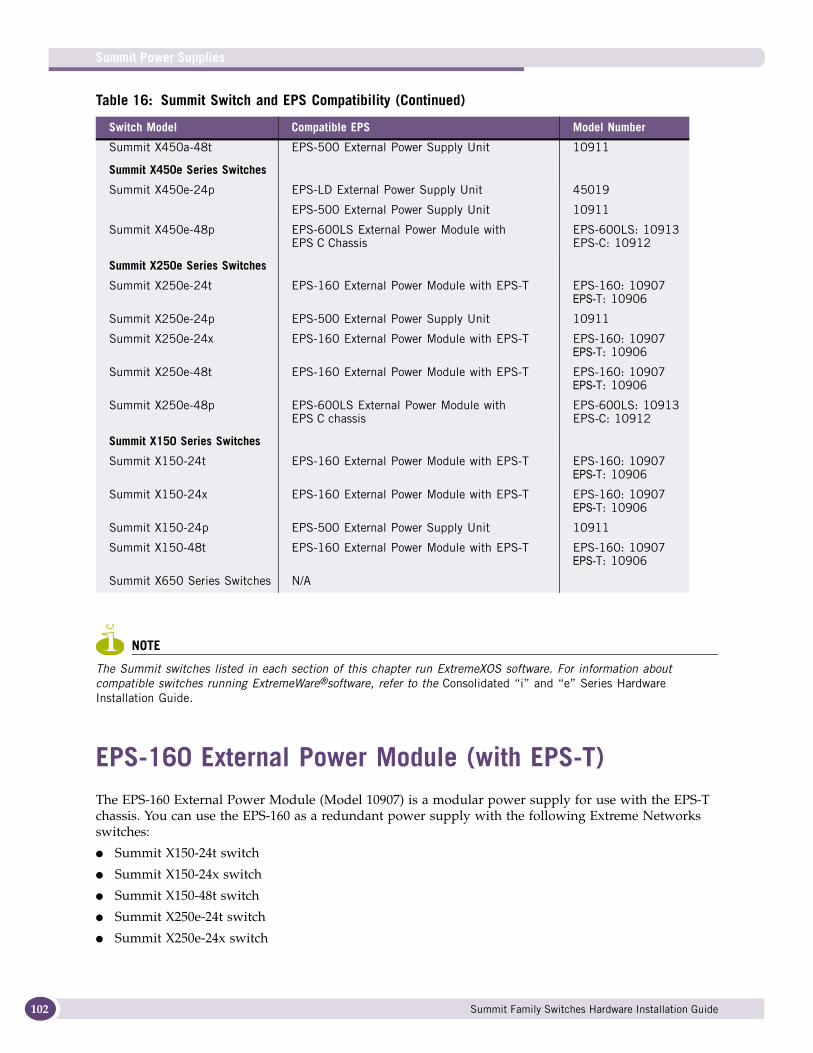
Summit Power Supplies
102
NOTE
The Summit switches listed in each section of this chapter run ExtremeXOS software. For information about compatible switches running ExtremeWare®software, refer to the Consolidated “i” and “e” Series Hardware Installation Guide.
EPS-160 External Power Module (with EPS-T)The EPS-160 External Power Module (Model 10907) is a modular power supply for use with the EPS-T chassis. You can use the EPS-160 as a redundant power supply with the following Extreme Networks switches:
● Summit X150-24t switch
● Summit X150-24x switch
● Summit X150-48t switch
● Summit X250e-24t switch
● Summit X250e-24x switch
Summit X450a-48t EPS-500 External Power Supply Unit 10911
Summit X450e Series Switches
Summit X450e-24p EPS-LD External Power Supply Unit 45019
EPS-500 External Power Supply Unit 10911
Summit X450e-48p EPS-600LS External Power Module with EPS C Chassis
EPS-600LS: 10913EPS-C: 10912
Summit X250e Series Switches
Summit X250e-24t EPS-160 External Power Module with EPS-T EPS-160: 10907EPS-T: 10906
Summit X250e-24p EPS-500 External Power Supply Unit 10911
Summit X250e-24x EPS-160 External Power Module with EPS-T EPS-160: 10907EPS-T: 10906
Summit X250e-48t EPS-160 External Power Module with EPS-T EPS-160: 10907EPS-T: 10906
Summit X250e-48p EPS-600LS External Power Module with EPS C chassis
EPS-600LS: 10913EPS-C: 10912
Summit X150 Series Switches
Summit X150-24t EPS-160 External Power Module with EPS-T EPS-160: 10907EPS-T: 10906
Summit X150-24x EPS-160 External Power Module with EPS-T EPS-160: 10907EPS-T: 10906
Summit X150-24p EPS-500 External Power Supply Unit 10911
Summit X150-48t EPS-160 External Power Module with EPS-T EPS-160: 10907EPS-T: 10906
Summit X650 Series Switches N/A
Table 16: Summit Switch and EPS Compatibility (Continued)
Switch Model Compatible EPS Model Number
Summit Family Switches Hardware Installation Guide
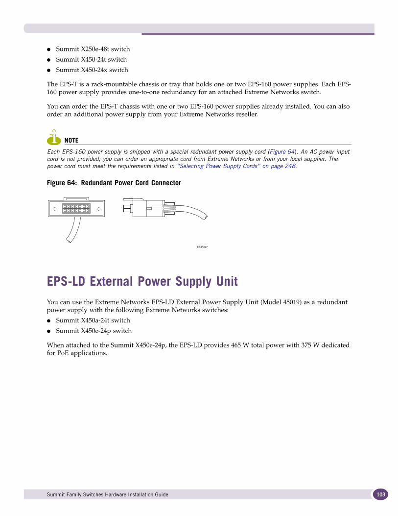
● Summit X250e-48t switch
● Summit X450-24t switch
● Summit X450-24x switch
The EPS-T is a rack-mountable chassis or tray that holds one or two EPS-160 power supplies. Each EPS-160 power supply provides one-to-one redundancy for an attached Extreme Networks switch.
You can order the EPS-T chassis with one or two EPS-160 power supplies already installed. You can also order an additional power supply from your Extreme Networks reseller.
NOTE
Each EPS-160 power supply is shipped with a special redundant power supply cord (Figure 64). An AC power input cord is not provided; you can order an appropriate cord from Extreme Networks or from your local supplier. The power cord must meet the requirements listed in “Selecting Power Supply Cords” on page 248.
Figure 64: Redundant Power Cord Connector
EPS-LD External Power Supply UnitYou can use the Extreme Networks EPS-LD External Power Supply Unit (Model 45019) as a redundant power supply with the following Extreme Networks switches:
● Summit X450a-24t switch
● Summit X450e-24p switch
When attached to the Summit X450e-24p, the EPS-LD provides 465 W total power with 375 W dedicated for PoE applications.
ES4K027
Summit Family Switches Hardware Installation Guide 103
Summit Power Supplies
104
EPS-500 External Power Supply UnitThe Extreme Networks EPS-500 External Power Supply Unit (Model 10911) provides additional power to compatible Power over Ethernet (PoE) switches and other Extreme switches. You can use the EPS-500 power supply as a redundant power supply with the following Extreme Networks switches:
● Summit X150-24p switch
● Summit X250e-24p switch
● Summit X350-24t switch
● Summit X350-48t switch
● Summit X450a-24t switch
● Summit X450a-24x switch
● Summit X450a-48t switch
● Summit X450e 24p switch
The EPS-500 power supply provides up to 500 W of total power and up to 375 W of power dedicated to PoE applications. When this power supply is used one of the listed Summit switches, the internal and external power supplies are fully fault tolerant and load-sharing. If one power supply fails, the other power supply will provide sufficient power to operate the switch.
EPS-150DC External Power Module (with EPS-T2)The EPS-150DC External Power Module (Model 10909) is a modular power supply for use in the EPS-T2 External Power System Tray. You can use the EPS-150DC as a redundant power supply with the following Extreme Networks switches:
● Summit X250e-24tDC switch
● Summit X250e-24xDC switch
● Summit X250e-48tDC switch
● Summit X450a-24tDC switch
● Summit X450a-24xDC switch
● Summit X450a-48tDC switch
When this power supply is used one of the listed Summit switches, the internal and external power supplies are fully fault tolerant and load-sharing. If one power supply fails, the other power supply will provide sufficient power to operate the switch.
The EPS-T2 is a rack-mountable chassis or tray that holds one or two EPS-150DC power supplies. Each EPS-150DC provides one-to-one redundancy to an attached Extreme switch. You must install the EPS-150DC power supply in the EPS-T2 tray.
NOTE
For centralized DC power connection, this product is intended to be installed in restricted access locations (dedicated equipment rooms, equipment closets, or the like) in accordance with Articles 110-16, 110-17, and 110-18 of the National Electric Code, ANSI/NFPA 70.
Summit Family Switches Hardware Installation Guide
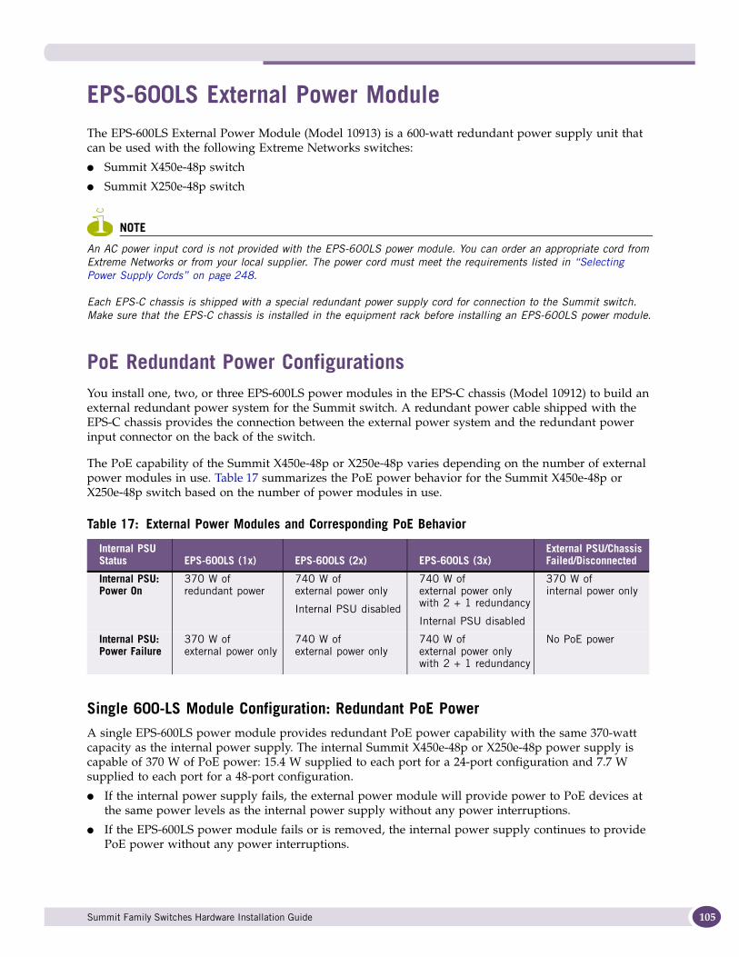
EPS-600LS External Power ModuleThe EPS-600LS External Power Module (Model 10913) is a 600-watt redundant power supply unit that can be used with the following Extreme Networks switches:
● Summit X450e-48p switch
● Summit X250e-48p switch
NOTE
An AC power input cord is not provided with the EPS-600LS power module. You can order an appropriate cord from Extreme Networks or from your local supplier. The power cord must meet the requirements listed in “Selecting Power Supply Cords” on page 248.
Each EPS-C chassis is shipped with a special redundant power supply cord for connection to the Summit switch. Make sure that the EPS-C chassis is installed in the equipment rack before installing an EPS-600LS power module.
PoE Redundant Power ConfigurationsYou install one, two, or three EPS-600LS power modules in the EPS-C chassis (Model 10912) to build an external redundant power system for the Summit switch. A redundant power cable shipped with the EPS-C chassis provides the connection between the external power system and the redundant power input connector on the back of the switch.
The PoE capability of the Summit X450e-48p or X250e-48p varies depending on the number of external power modules in use. Table 17 summarizes the PoE power behavior for the Summit X450e-48p or X250e-48p switch based on the number of power modules in use.
Single 600-LS Module Configuration: Redundant PoE PowerA single EPS-600LS power module provides redundant PoE power capability with the same 370-watt capacity as the internal power supply. The internal Summit X450e-48p or X250e-48p power supply is capable of 370 W of PoE power: 15.4 W supplied to each port for a 24-port configuration and 7.7 W supplied to each port for a 48-port configuration.
● If the internal power supply fails, the external power module will provide power to PoE devices at the same power levels as the internal power supply without any power interruptions.
● If the EPS-600LS power module fails or is removed, the internal power supply continues to provide PoE power without any power interruptions.
Table 17: External Power Modules and Corresponding PoE Behavior
Internal PSU Status EPS-600LS (1x) EPS-600LS (2x) EPS-600LS (3x)
External PSU/Chassis Failed/Disconnected
Internal PSU: Power On
370 W of redundant power
740 W of external power only
Internal PSU disabled
740 W of external power only with 2 + 1 redundancy
Internal PSU disabled
370 W of internal power only
Internal PSU: Power Failure
370 W of external power only
740 W of external power only
740 W of external power only with 2 + 1 redundancy
No PoE power
Summit Family Switches Hardware Installation Guide 105

Summit Power Supplies
106
Dual 600-LS Module Configuration: Full PowerTwo EPS-600LS power modules provide full power at 740 W, which allows 15.4 W of PoE power to all 48 ports. In this full-power configuration, the internal power supply is disabled, and therefore redundant power is not available.
Triple 600-LS Module Configuration: Full Redundant PowerThree EPS-600LS power modules provide the full 740 W of power for 15.4 W of PoE power to all 48 ports. In addition, this configuration provides 2:1 redundancy. Should one of the EPS-600LS power modules fail, the third power module continues to provide uninterrupted full PoE power. The internal power supply is disabled in this configuration.
Internal-to-External PSU TransferThis section describes the conditions that would cause the Summit X450e-48p or X250e-48p switch to draw power from the external power unit.
Internal PSU Failure with Single EPS-600LS Module. When an EPS-C with a single EPS-600LS is connected to the Summit X450e-48p or X250e-48p switch and the internal PSU fails, power is drawn from the EPS-600LS without power interruption to the PoE connected devices.
Two or Three EPS-600LS Modules. When the Summit X450e-48p or X250e-48p switch detects that an EPS-C is connected and providing stable power from two or three EPS-600LS power modules, the PoE power budget is automatically recalculated to enable 740 W of PoE power. The internal PSU is disabled to prevent damage from excessive current demands beyond the internal PSU's capabilities.
External-to-Internal PSU TransferThis section describes the conditions where power from an external power module either fails or is disconnected.
Active Internal PSU with Single 600-LS Module Failure. When an EPS-C configured with a single EPS-600LS module is connected to the Summit X450e-48p or X250e-48p switch and the EPS-600LS fails or is disconnected, power is drawn from the internal PSU without power interruption to the PoE connected devices.
Inactive Internal PSU with a Dual EPS-600LS Configuration and Module Failure. This section describes the PoE behavior when an EPS-C chassis configured with two EPS-600LS modules is connected to the Summit X450e-48p or X250e-48p switch and one or both EPS-600LS modules fail or are disconnected.
It is possible for one external power module to fail while the second power module continues to function. If one EPS-600LS fails, the PoE power budget is automatically reduced to 370 W for the Summit X450e-48p or X250e-48p switch. PoE port power management occurs as described in the Power over Ethernet section of the ExtremeXOS Concepts Guide. With only a single operating power module, the remaining EPS-600LS behaves as a redundant power module. The internal PSU is returned to an active state to provide redundant capability.
If both external power modules fail or are disconnected, PoE power is interrupted while transferring PoE power back to the internal PSU. The internal PSU is then limited to 370 W of PoE power. The PoE power budget is automatically adjusted accordingly. Power management will occur as described in the Power over Ethernet section of the ExtremeXOS Concepts Guide.
Summit Family Switches Hardware Installation Guide
Disconnecting the EPS-C/EPS-600LS. To manually disconnect an EPS-C or to remove the EPS-600LS modules, the recommended practice is to disconnect the EPS-600LS modules one at a time, pausing two seconds between each EPS-600LS disconnect. This enables a graceful power transition from the external PSUs to the internal PSU.
Example: Two active EPS-600LS modules in an EPS-C
a Unplug one EPS-600LS unit from its power source.
PoE power is automatically reduced to 370 watts and the internal PSU is enabled providing redundant 370 watt PoE power.
b Wait at least two seconds before disconnecting the remaining EPS-600LS unit.
c Unplug the second EPS-600LS unit from its power source.
The internal PSU is already enabled and provides uninterrupted 370 watts of PoE power.
NOTE
After an EPS-600LS unit is disconnected from its power source, it may be removed from the EPS-C. See “Removing an EPS-600LS Power Module” on page 221 for complete disconnect and removal details.
d Disconnect the EPS-C from the switch.
Summit X480 Power SuppliesThe Summit X480 series switches can be powered by either of the following power supplies:
● Summit X480 AC power supply (Model 10917)
● Summit X480 DC power supply (Model 10918)
Either power supply provides 450 W of power to the switch.
The Summit X480 series switches accommodate one or two Summit X480 PSUs. In a redundant power configuration, both power supplies are fully fault-tolerant and load-sharing. You can remove one power supply without interrupting switch operation.
An AC power input cord is not provided with the Summit X480 AC power supply. You can order an appropriate cord from Extreme Networks or from your local supplier. The power cord must meet the requirements listed in “Selecting Power Supply Cords” on page 248.
Summit Family Switches Hardware Installation Guide 107
Summit Power Supplies
108
Summit X650 Power SuppliesThe Summit X650 series switches can be powered by either of the following power supplies:
● Summit X650 AC PSU (Model 10914)
● Summit X650 DC PSU (Model 10915)
Either power supply provides 850 W of power to the switch.
The Summit X650 series switches accommodate one or two Summit X650 PSUs. In a redundant power configuration, both power supplies are fully fault-tolerant and load-sharing. You can remove one power supply without interrupting switch operation.
An AC power input cord is not provided with the Summit X650 AC power supply. You can order an appropriate cord from Extreme Networks or from your local supplier. The power cord must meet the requirements listed in “Selecting Power Supply Cords” on page 248.
NOTE
Extreme Networks does not recommended using the Summit X650 DC PSU in combination with a Summit X650 AC PSU in the same Summit X650 series switch.
Summit Family Switches Hardware Installation Guide
2 Installing the Hardware

3 Site Preparation
This chapter includes the following sections:
● Planning Your Site on page 111
● Meeting Site Requirements on page 112
● Evaluating and Meeting Cable Requirements on page 116
● Meeting Power Requirements on page 121
● Applicable Industry Standards on page 123
By carefully planning your site, you can maximize the performance of your existing network and ensure that it is ready to migrate to future networking technologies.
The information in this chapter is intended for the system administrator, network equipment technician, network manager, or facilities manager responsible for installing and managing the network hardware. The chapter assumes a working knowledge of local area network (LAN) operations, and a familiarity with communications protocols that are used on interconnected LANs.
Installation, maintenance, and removal of a switch, chassis, or its components must be done by qualified service personnel only. Qualified service personnel have had appropriate technical training and experience that is necessary to be aware of the hazards to which they are exposed when performing a task and of measures to minimize the danger to themselves or other people.
NOTE
Before installing or removing any components of the system, or before carrying out any maintenance procedures, read the safety information in Appendix A of this guide.
Planning Your SiteTo install your equipment successfully, you should plan your site carefully. The site planning process has three major parts:
● Meeting site requirements
The physical installation site must meet the following requirements for a safe and successful installation:
■ Building and electrical code requirements
■ Environmental, safety, and thermal requirements for the equipment you plan to install
■ Equipment rack requirements
● Evaluating and meeting cable requirements
After examining your physical site and verifying that all environment requirements are met, evaluate and compare your existing cable plant with the requirements of the Extreme Networks equipment to determine if you need to install new cables.
Summit Family Switches Hardware Installation Guide 111
Site Preparation
112
● Meeting power requirements
To run your equipment safely, you must meet the specific power requirements for each switch and external power supply unit installed in the system. For power specifications of the switches, see the specific switch listings in Appendix B, “Technical Specifications.” For power specifications of the external power supplies, see “Summit External Power Supplies” on page 291.
Meeting Site RequirementsThis section requirements to consider when preparing your installation site, including:
● Operating Environment Requirements
● Rack Specifications and Recommendations
Operating Environment RequirementsVerify that your site meets all environmental and safety requirements.
Virtually all areas of the United States are regulated by building codes and standards. During the early planning stages of installing or modifying your LAN, it is important that you develop a thorough understanding of the regulations that pertain to your location and industry.
Building and Electrical CodesBuilding and electrical codes vary depending on your location. Comply with all code specifications when planning your site and installing cable. This section lists resources for obtaining additional information.
Information about major building codes is located at the following websites:
● International Code Council (ICC); 5203 Leesburg Pike; Falls Church, Virginia 22041 USA.
http://www.iccsafe.org
http://www.sbcci.org
Five authorities on electrical codes are:
● National Electrical Code (NEC) Classification (USA only)—a recognized authority on safe electrical wiring. Federal, state, and local governments use NEC standards to establish their own laws, ordinances, and codes on wiring specifications. The NEC classification is published by the National Fire Protection Association (NFPA). The address is NFPA; 1 Batterymarch Park; Quincy, Massachusetts 02169 USA. http://www.nfpa.org
● Underwriters’ Laboratory (UL) (USA only)—an independent research and testing laboratory. UL evaluates the performance and capability of electrical wiring and equipment to determine whether they meet certain safety standards when properly used. Acceptance is usually indicated by the words “UL Approved” or “UL Listed.” The address is UL; 333 Pfingsten Road; Northbrook, Illinois 60062-2096 USA. http://www.ul.com
● National Electrical Manufacturing Association (NEMA) (USA only)—an organization of electrical product manufacturers. Members develop consensus standards for cables, wiring, and electrical components. The address is NEMA; 1300 N. 17th Street; Rosslyn, Virginia 22209. http://www.nema.org
● Electronics Industries Alliance (EIA)—a trade association that develops technical standards, disseminates marketing data, and maintains contact with government agencies in matters relating to
Summit Family Switches Hardware Installation Guide
the electronics industry. The address is EIA; 2500 Wilson Boulevard; Arlington, Virginia 22201 USA. http://www.eia.org
● Federal Communications Commission (FCC) (USA only)—a commission that regulates all interstate and foreign electrical communication systems that originate in the United States according to the Communications Act of 1934. The FCC regulates all U.S. telephone and cable systems. The address is FCC; 445 12th Street S.W.; Washington, D.C. 20554 USA. http://www.fcc.gov
Wiring Closet ConsiderationsBe aware of the following recommendations for your wiring closet:
● Be sure that your system is easily accessible for installation and service. See “Rack Specifications and Recommendations” on page 114 for information.
● Use appropriate AC or DC power, power distribution, and grounding for your specific installation.
● Use a vinyl floor covering in your wiring closet. (Concrete floors accumulate dust, and carpets can cause static electricity.)
● Prevent unauthorized access to wiring closets by providing door locks. Install the equipment in a secured, enclosed, and restricted access location, ensuring that only qualified service personnel have access to the equipment.
● Provide adequate overhead lighting for easy maintenance.
● Be sure that each wiring closet has a suitable ground. All equipment racks and equipment installed in the closet should be grounded.
● Be sure that all system environmental requirements are met, such as ambient temperature and humidity.
NOTE
Extreme Networks recommends that you consult an electrical contractor for commercial building and wiring specifications.
TemperatureExtreme Networks equipment generates a significant amount of heat. It is essential that you provide a temperature-controlled environment for both performance and safety.
Install the equipment only in a temperature- and humidity-controlled indoor area that is free of airborne materials that can conduct electricity. Too much humidity can cause a fire. Too little humidity can produce electrical shock and fire.
Follow these general thermal recommendations for your wiring closet:
● Be sure that the ventilation in the wiring closet is adequate to maintain a temperature below 104° F (40° C).
● Install a reliable air conditioning and ventilation system.
● Keep the ventilation in the wiring closet running during non-business hours; otherwise, the equipment can overheat.
● Maintain an ambient operating temperature of 32° to 104° F (0° to 40° C).
● Maintain a storage temperature of -40° to 158° F (-40° to 70° C).
Summit Family Switches Hardware Installation Guide 113
Site Preparation
114
NOTE
As with all electrical equipment, Extreme Networks product lifetimes degrade with increased temperature. If possible, temperatures should be kept at approximately 78° F (25° C) or lower.
HumidityTo maximize equipment life, keep operating humidity between 50% and 70% relative humidity (non-condensing) during typical operation. The equipment can operate between 10% and 95% relative humidity (non-condensing) for short intervals.
Spacing Requirements and AirflowBe sure that cables and other equipment do not block the air intake or outflow on an Extreme Networks Summit family switch. It is best to have at least 3 inches (8 cm) of clear space in front of the air intake and outflow vents on the sides of the switch; airflow moves from side to side. For proper airflow through a Summit family switch, leave clear space on the left and right sides of the switch.
Depending on other conditions in the equipment room, it may be possible to install the switches closer to each other; consult your Extreme Networks Customer Support representative for guidance.
Electrostatic Discharge Your system must be protected from static electricity or electrostatic discharge (ESD). Take the following measures to ensure optimum system performance:
● Remove materials that can cause electrostatic generation (such as synthetic resins) from the wiring closet. Check the appropriateness of floor mats and flooring.
● Connect metal chassis, conduit, and other metals to ground using dedicated grounding lines.
● Use electrostatically safe equipment. If you are working with pluggable interface modules, wear an ESD-preventive wrist strap and connect the metal end to a grounded equipment rack or other source of ground.
Rack Specifications and RecommendationsRacks should conform to conventional standards. In the United States, use EIA Standard RS-310C: Racks, Panels, and Associated Equipment. In countries other than the United States, use IEC Standard 297. In addition, verify that your rack meets the basic mechanical, space, and earthquake requirements that are described in this section.
Summit Family Switches Hardware Installation Guide

Mechanical Recommendations for the RackUse equipment racks that meet the following mechanical recommendations:
● Use an open style, 19-inch rack to facilitate easy maintenance and to provide proper ventilation.
● Use a rack made of steel or aluminum.
● The rack should use the universal mounting rail hole pattern that is identified in IEC Standard 297.
● The rack should have designated earth grounding connections (typically on the base).
● The rack must meet earthquake safety requirements equal to that of the installed chassis.
● The mounting holes should be flush with the rails to accommodate the chassis.
● The rack should support approximately 600 pounds (272 kilograms).
Protective Grounding for the RackUse a rack grounding kit and a ground conductor that is carried back to earth or to another suitable building ground.
At a minimum, follow these guidelines to ground equipment racks to the earth ground:
● CAD weld appropriate wire terminals to building I-beams or earth ground rods.
● For a Summit DC-powered switch, use a minimum 14 AWG stranded copper wire for grounding.
AC-powered Summit switches do not need separate chassis grounding.
● Position the earth ground as close to the equipment rack as possible to maintain the shortest wiring distance possible.
● Use a ground impedance tester or micro-ohm meter to test the quality of earth ground connection at the chassis. This will ensure good grounding between the chassis, rack, and earth ground.
NOTE
Because building codes vary worldwide, Extreme Networks strongly recommends that you consult an electrical contractor to ensure proper equipment grounding for your specific installation.
Space Requirements for the RackProvide enough space in front of and behind the switch so that you can service it easily. Allow a minimum of 48 inches (122 cm) in front of the rack and 30 inches (76 cm) behind the rack. When using a relay (two-post) rack, provide a minimum of 24 inches (61 cm) of space behind the mounted equipment. Extra room on each side is optional.
WARNING!
Extreme Networks switches do not have a switch for turning power to the unit on and off. For systems using an AC power supply, power to the switch is disconnected by removing the wall plug from the electrical outlet.
For DC-powered Summit switches (X450a-24tDC, X450a-24xDC, and X450a-48tDC) and the EPS-150DC power supply, turn off power to the chassis by de-energizing the circuit that feeds the power supply; this is usually accomplished by turning off a circuit breaker. Disconnecting the DC wiring harness from the DC power source requires the performance of a qualified, licensed electrician.
Summit Family Switches Hardware Installation Guide 115
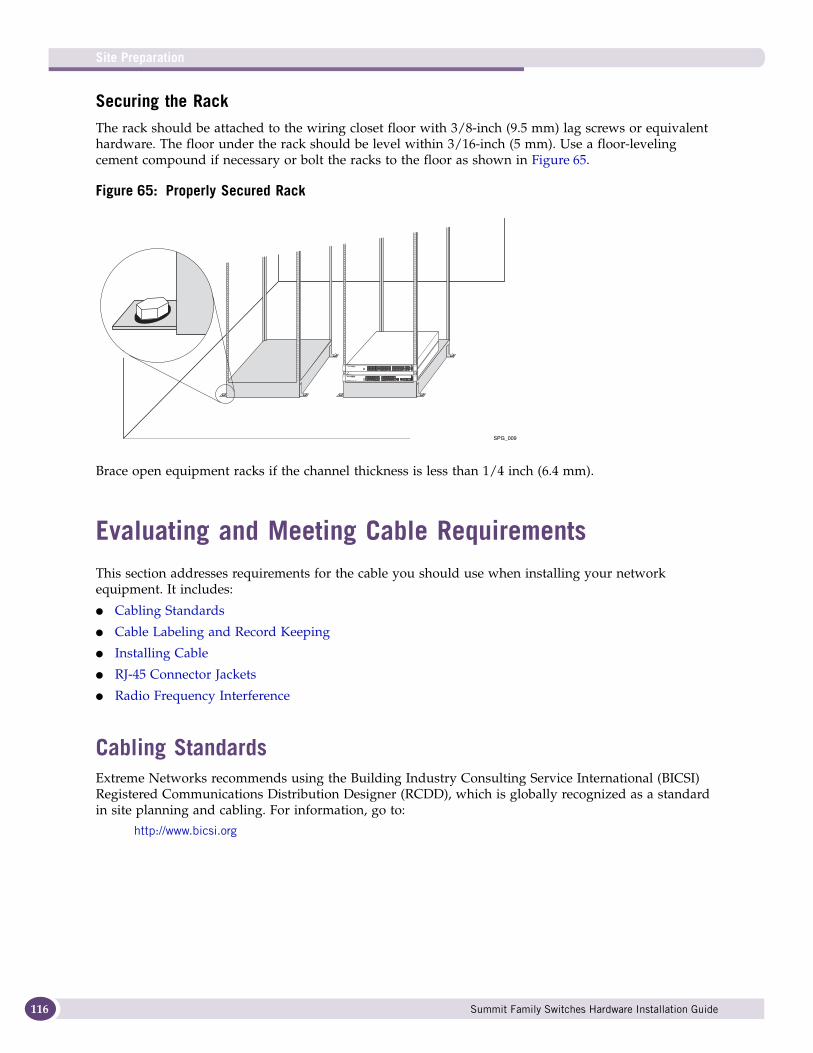
Site Preparation
116
Securing the RackThe rack should be attached to the wiring closet floor with 3/8-inch (9.5 mm) lag screws or equivalent hardware. The floor under the rack should be level within 3/16-inch (5 mm). Use a floor-leveling cement compound if necessary or bolt the racks to the floor as shown in Figure 65.
Figure 65: Properly Secured Rack
Brace open equipment racks if the channel thickness is less than 1/4 inch (6.4 mm).
Evaluating and Meeting Cable RequirementsThis section addresses requirements for the cable you should use when installing your network equipment. It includes:
● Cabling Standards
● Cable Labeling and Record Keeping
● Installing Cable
● RJ-45 Connector Jackets
● Radio Frequency Interference
Cabling StandardsExtreme Networks recommends using the Building Industry Consulting Service International (BICSI) Registered Communications Distribution Designer (RCDD), which is globally recognized as a standard in site planning and cabling. For information, go to:
http://www.bicsi.org
SPG_009
Summit Family Switches Hardware Installation Guide
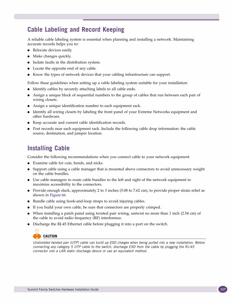
Cable Labeling and Record KeepingA reliable cable labeling system is essential when planning and installing a network. Maintaining accurate records helps you to:
● Relocate devices easily.
● Make changes quickly.
● Isolate faults in the distribution system.
● Locate the opposite end of any cable.
● Know the types of network devices that your cabling infrastructure can support.
Follow these guidelines when setting up a cable labeling system suitable for your installation:
● Identify cables by securely attaching labels to all cable ends.
● Assign a unique block of sequential numbers to the group of cables that run between each pair of wiring closets.
● Assign a unique identification number to each equipment rack.
● Identify all wiring closets by labeling the front panel of your Extreme Networks equipment and other hardware.
● Keep accurate and current cable identification records.
● Post records near each equipment rack. Include the following cable drop information: the cable source, destination, and jumper location.
Installing CableConsider the following recommendations when you connect cable to your network equipment:
● Examine cable for cuts, bends, and nicks.
● Support cable using a cable manager that is mounted above connectors to avoid unnecessary weight on the cable bundles.
● Use cable managers to route cable bundles to the left and right of the network equipment to maximize accessibility to the connectors.
● Provide enough slack, approximately 2 to 3 inches (5.08 to 7.62 cm), to provide proper strain relief as shown in Figure 66.
● Bundle cable using hook-and-loop straps to avoid injuring cables.
● If you build your own cable, be sure that connectors are properly crimped.
● When installing a patch panel using twisted pair wiring, untwist no more than 1 inch (2.54 cm) of the cable to avoid radio frequency (RF) interference.
● Discharge the RJ-45 Ethernet cable before plugging it into a port on the switch.
CAUTION
Unshielded twisted pair (UTP) cable can build up ESD charges when being pulled into a new installation. Before connecting any category 5 UTP cable to the switch, discharge ESD from the cable by plugging the RJ-45 connector into a LAN static discharge device or use an equivalent method.
Summit Family Switches Hardware Installation Guide 117
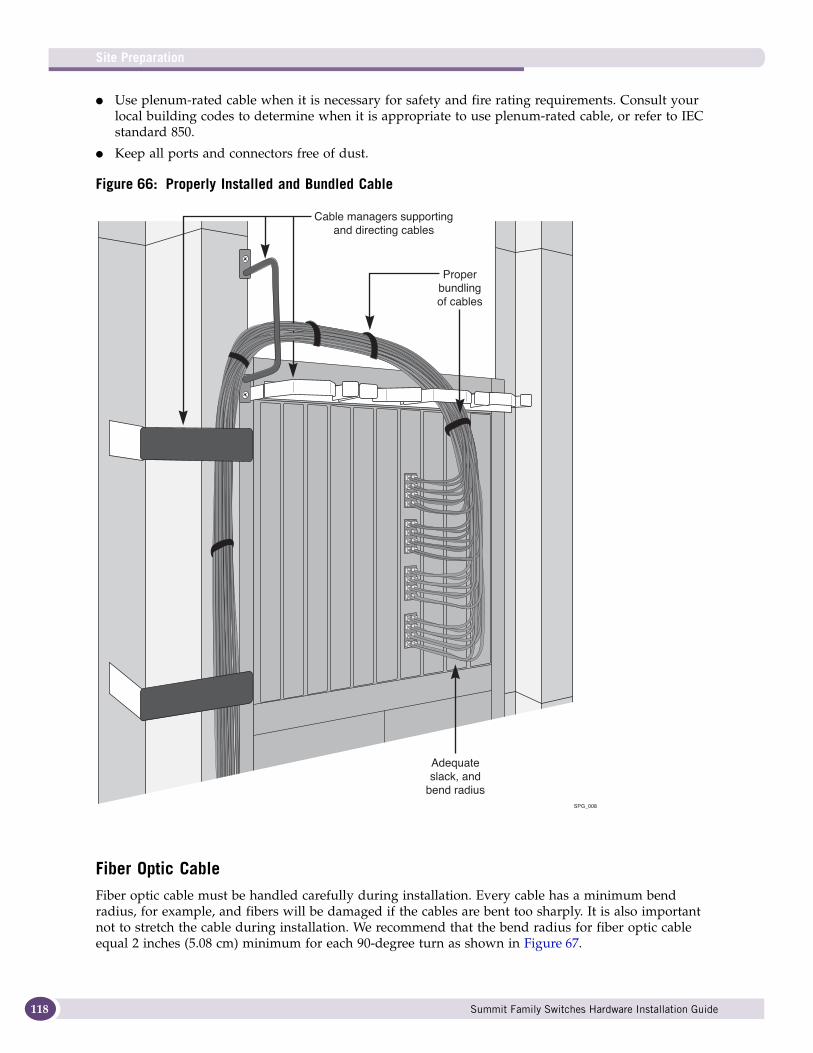
Site Preparation
118
● Use plenum-rated cable when it is necessary for safety and fire rating requirements. Consult your local building codes to determine when it is appropriate to use plenum-rated cable, or refer to IEC standard 850.
● Keep all ports and connectors free of dust.
Figure 66: Properly Installed and Bundled Cable
Fiber Optic CableFiber optic cable must be handled carefully during installation. Every cable has a minimum bend radius, for example, and fibers will be damaged if the cables are bent too sharply. It is also important not to stretch the cable during installation. We recommend that the bend radius for fiber optic cable equal 2 inches (5.08 cm) minimum for each 90-degree turn as shown in Figure 67.
SPG_008
Properbundlingof cables
Cable managers supportingand directing cables
Adequateslack, and
bend radius
Summit Family Switches Hardware Installation Guide
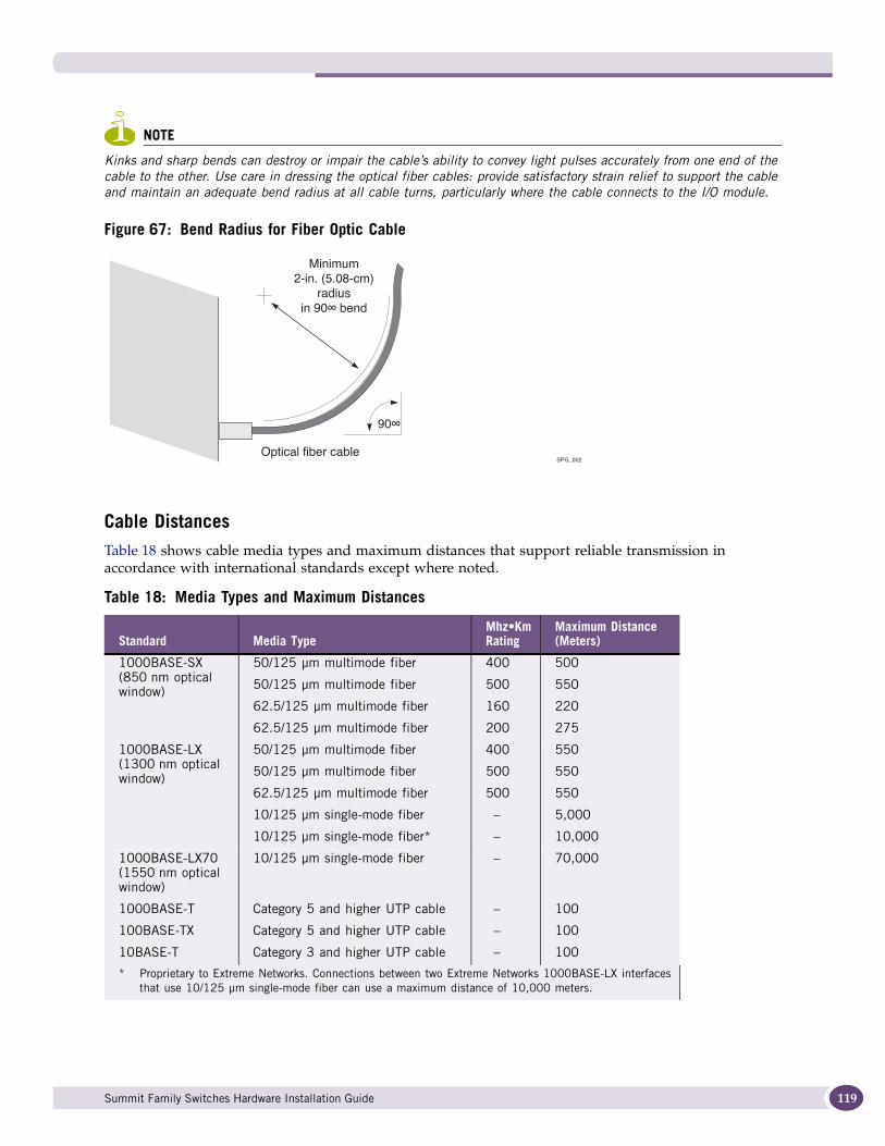
NOTE
Kinks and sharp bends can destroy or impair the cable’s ability to convey light pulses accurately from one end of the cable to the other. Use care in dressing the optical fiber cables: provide satisfactory strain relief to support the cable and maintain an adequate bend radius at all cable turns, particularly where the cable connects to the I/O module.
Figure 67: Bend Radius for Fiber Optic Cable
Cable DistancesTable 18 shows cable media types and maximum distances that support reliable transmission in accordance with international standards except where noted.
Table 18: Media Types and Maximum Distances
Standard Media TypeMhz•Km Rating
Maximum Distance (Meters)
1000BASE-SX(850 nm optical window)
50/125 μm multimode fiber
50/125 μm multimode fiber
62.5/125 μm multimode fiber
62.5/125 μm multimode fiber
400
500
160
200
500
550
220
275
1000BASE-LX(1300 nm optical window)
50/125 μm multimode fiber
50/125 μm multimode fiber
62.5/125 μm multimode fiber
10/125 μm single-mode fiber
10/125 μm single-mode fiber*
400
500
500
–
–
550
550
550
5,000
10,000
1000BASE-LX70(1550 nm optical window)
10/125 μm single-mode fiber – 70,000
1000BASE-T
100BASE-TX
10BASE-T
Category 5 and higher UTP cable
Category 5 and higher UTP cable
Category 3 and higher UTP cable
–
–
–
100
100
100
* Proprietary to Extreme Networks. Connections between two Extreme Networks 1000BASE-LX interfaces that use 10/125 μm single-mode fiber can use a maximum distance of 10,000 meters.
SPG_002
Minimum2-in. (5.08-cm)
radiusin 90∞ bend
90∞
Optical fiber cable
Summit Family Switches Hardware Installation Guide 119
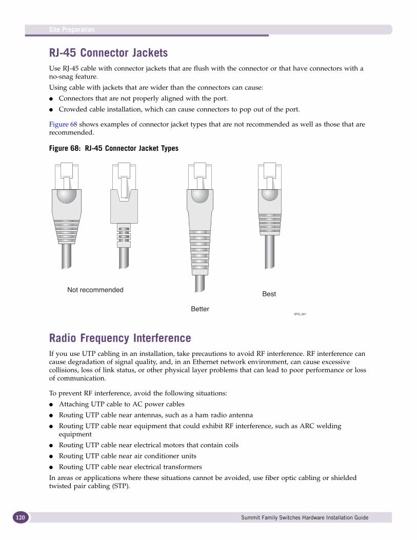
Site Preparation
120
RJ-45 Connector JacketsUse RJ-45 cable with connector jackets that are flush with the connector or that have connectors with a no-snag feature.
Using cable with jackets that are wider than the connectors can cause:
● Connectors that are not properly aligned with the port.
● Crowded cable installation, which can cause connectors to pop out of the port.
Figure 68 shows examples of connector jacket types that are not recommended as well as those that are recommended.
Figure 68: RJ-45 Connector Jacket Types
Radio Frequency InterferenceIf you use UTP cabling in an installation, take precautions to avoid RF interference. RF interference can cause degradation of signal quality, and, in an Ethernet network environment, can cause excessive collisions, loss of link status, or other physical layer problems that can lead to poor performance or loss of communication.
To prevent RF interference, avoid the following situations:
● Attaching UTP cable to AC power cables
● Routing UTP cable near antennas, such as a ham radio antenna
● Routing UTP cable near equipment that could exhibit RF interference, such as ARC welding equipment
● Routing UTP cable near electrical motors that contain coils
● Routing UTP cable near air conditioner units
● Routing UTP cable near electrical transformers
In areas or applications where these situations cannot be avoided, use fiber optic cabling or shielded twisted pair cabling (STP).
0.1" = 1mm actual39.37% : 254%
SPG_001
Not recommended
Better
Best
Summit Family Switches Hardware Installation Guide
Meeting Power RequirementsThis section describes power requirements, including:
● PoE Devices
● Power Supply Requirements
● AC Power Cables
● Uninterruptible Power Supply Requirements
PoE DevicesWhen connecting power over Ethernet (PoE) devices to a PoE switch, all connections between the PoE device and the switch must remain within the same building and use a low-voltage power distribution system per IEEE 802.3af.
Power Supply RequirementsFollow these recommendations when you plan power supply connections for the Summit family switches:
● Place the equipment in an area that accommodates the power consumption and component heat dissipation specifications.
● Be sure that your power supply meets the site DC power or AC power requirements of the network equipment.
● When you connect power to installed equipment, do not make this connection through an extension cord or power strip.
● If your switch includes more than one power supply, connect each power supply to a different, independent power source.
If a power source fails, it will affect only the switch power supply to which it is connected. If all switch power supplies are connected to a single power source, the entire switch is vulnerable to a power source failure.
● In regions that are susceptible to electrical storms, we recommend that you plug your system into a surge suppressor.
For power specifications for the Summit family switches, see Appendix B, “Technical Specifications.”
AC Power CablesAC power input cords are not provided with Summit switches and power supplies. You can purchase AC power cords for use in the US and Canada from Extreme Networks or from your local supplier.
Power supply cords for use outside of the United States and Canada are typically provided separately by third-party distribution centers. Make sure that the power cord you use is certified for the country of end use and suitable for the device.
The power cord must meet the requirements listed in “Selecting Power Supply Cords” on page 248.
Summit Family Switches Hardware Installation Guide 121

Site Preparation
122
Uninterruptible Power Supply RequirementsAn uninterruptible power supply (UPS) is a device that sits between a power supply (such as a wall outlet) and a device (such as a switch) to prevent outages, sags, surges, and bad harmonics from adversely affecting the performance of the device.
A UPS traditionally can perform the following functions:
● Absorb relatively small power surges.
● Smooth out noisy power sources.
● Continue to provide power to equipment during line sags.
● Provide power for a period of time after a blackout has occurred.
In addition, some UPS devices or UPS-plus-software combinations provide the following functions:
● Automatically shut down equipment during long power outages.
● Monitor and log power supply status.
● Display the voltage (current draw) of the equipment.
● Restart equipment after a long power outage.
● Display the voltage currently on the line.
● Provide alarms on certain error conditions.
● Provide short-circuit protection.
Selecting a UPS To determine UPS requirements for your switch, answer these questions:
● What are the amperage requirements?
● What is the longest potential time period that the UPS would be required to supply backup power?
● Where will the UPS be installed?
● What is the maximum transition time that the installation will allow? (See “UPS Transition Time” on page 123)
NOTE
Extreme Networks recommends that you use a UPS that provides online protection.
Calculating Volt-Amperage RequirementsTo determine the size of UPS that you need:
1 Locate the voltage and amperage requirements for each piece of equipment. These numbers are usually located on a sticker on the back or bottom of your equipment. Then multiply the numbers together to get Volt-Amperes (VA):
VA = Volts x Amperes
2 Add the VA from all the pieces of equipment together to find the total VA requirement.
To determine the minimum volt-amperage requirements for your UPS, Extreme Networks recommends that you add 30% to the total.
Summit Family Switches Hardware Installation Guide
UPS Transition TimeTransition time is the time that is necessary for the UPS to transfer from utility power to full-load battery power. For Extreme Networks products, a transition time of less than 20 milliseconds is required for optimum performance.
DC Power RequirementsThis system should be installed in a DC-I battery return configuration.In a DC-I configuration, the battery return conductor should be connected directly to the central office power return bus, and not to the equipment frame or the grounding means of the equipment.
Applicable Industry StandardsFor more information, see the following ANSI/TIA/EIA standards:
● ANSI/TIA/EIA-568-A—discusses the six subsystems of a structured cabling system.
● ANSI/TIA/EIA-569-A—discusses design considerations.
● ANSI/TIA/EIA-606—discusses cabling system administration.
● ANSI/TIA/EIA-607—discusses commercial building grounding and bonding requirements.
You can access these standards at:
http://www.ansi.org
or
http://www.tiaonline.org
Summit Family Switches Hardware Installation Guide 123

Site Preparation
124
Summit Family Switches Hardware Installation Guide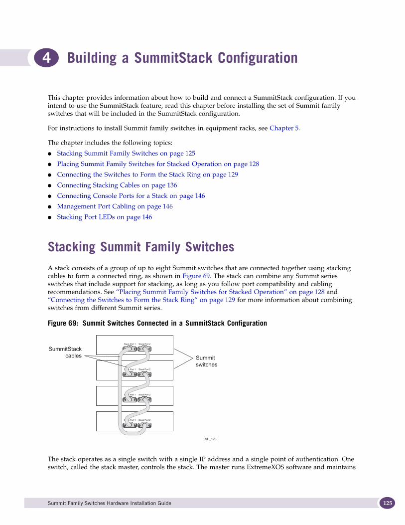
4 Building a SummitStack Configuration
This chapter provides information about how to build and connect a SummitStack configuration. If you intend to use the SummitStack feature, read this chapter before installing the set of Summit family switches that will be included in the SummitStack configuration.
For instructions to install Summit family switches in equipment racks, see Chapter 5.
The chapter includes the following topics:
● Stacking Summit Family Switches on page 125
● Placing Summit Family Switches for Stacked Operation on page 128
● Connecting the Switches to Form the Stack Ring on page 129
● Connecting Stacking Cables on page 136
● Connecting Console Ports for a Stack on page 146
● Management Port Cabling on page 146
● Stacking Port LEDs on page 146
Stacking Summit Family SwitchesA stack consists of a group of up to eight Summit switches that are connected together using stacking cables to form a connected ring, as shown in Figure 69. The stack can combine any Summit series switches that include support for stacking, as long as you follow port compatibility and cabling recommendations. See “Placing Summit Family Switches for Stacked Operation” on page 128 and “Connecting the Switches to Form the Stack Ring” on page 129 for more information about combining switches from different Summit series.
Figure 69: Summit Switches Connected in a SummitStack Configuration
The stack operates as a single switch with a single IP address and a single point of authentication. One switch, called the stack master, controls the stack. The master runs ExtremeXOS software and maintains
Stack Port 1 Stack Port 2
Stack Port 1 Stack Port 2
Stack Port 1 Stack Port 2
Stack Port 1 Stack Port 2
SH_176
Summitswitches
SummitStackcables
Summit Family Switches Hardware Installation Guide 125

Building a SummitStack Configuration
126
all the software tables for all the switches in the stack. A stack of switches can have only one master switch. All switches in the stack, including the master switch, are called nodes.
Slot NumbersA stack can be thought of as a virtual chassis. Each node operates as if it were occupying a slot in a chassis and is controlled by the master. The high-speed stacking links function like the backplane links of a chassis.
Each switch (or node) in the stack is assigned a “slot number” during the initial software configuration of the stack. Starting at the switch with the console connection, numbers are assigned in numerical order following the physical path of the connected stacking cables. For example, if you follow the cabling recommendations presented in “Connecting the Switches to Form the Stack Ring” on page 129 and configure a vertical stack from the console on the switch at the top of the physical stack, the switches Figure 71 will be assigned numbers 1 through 8 from the top down.
Each Summit switch has a seven-segment LED on its front panel, called the stack number indicator. When a stack is operating, the indicator displays the slot number for the switch. This LED does not light on switches that are not operating in stacking mode. A quick way to verify that the cable connections match the software configuration is to check the stack number indicator on each switch. If the slot numbers do not line up in the order you arranged the switches, this may indicate that the stacking cable setup differs from what you intended when you configured the software. In this case, reconnect the cables in the correct order and perform the software configuration again.
About RedundancyWhen your stack is operational, one switch is the primary (or master) switch that is responsible for running network protocols and managing the stack. To provide recovery in case of a break in the stack connections, you can configure redundancy by designating a backup switch to take over as master if the master switch fails. When you perform the initial software configuration of the stack, the “easy setup” configuration option automatically configures redundancy, with slot 1 as the master and slot 2 as the backup. You can also configure additional switches as “master-capable” to become a stack master in case the initial backup switch fails.
In a stack that combines Summit X480 series or X650 series switches with other Summit switch models, a Summit X480 or X650 series switch might provide more memory and more features than other Summit switch models in the stack. These differences can affect master node selection, backup node selection, and failover operation. The master and backup roles should be assigned to switches from the same series. For example, if the master node is a Summit X480 series switch, the backup node should also be a Summit X480 switch. Similarly, if the master node is a Summit X650 series switch, the backup node should also be a Summit X650 switch.
In a stack that combines Summit X480 series switches with Summit X650 series switches, Extreme Networks recommends assigning the master/backup roles to two Summit X480 series switches.
In a stack with multiple master-capable switches, it is possible for more than one switch to try become the stack master if the stack is physically severed. Such a dual-master condition would cause confusion and loss of connectivity in your network. To resolve a dual-master condition, you must be able to log in to each severed stack segment, either over the management network (using the Ethernet management port on a switch in the segment) or through a direct console port connection to each switch in the segment.
Summit Family Switches Hardware Installation Guide
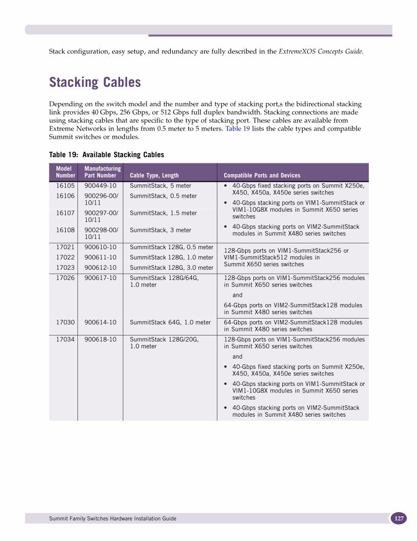
Stack configuration, easy setup, and redundancy are fully described in the ExtremeXOS Concepts Guide.
Stacking CablesDepending on the switch model and the number and type of stacking port,s the bidirectional stacking link provides 40 Gbps, 256 Gbps, or 512 Gbps full duplex bandwidth. Stacking connections are made using stacking cables that are specific to the type of stacking port. These cables are available from Extreme Networks in lengths from 0.5 meter to 5 meters. Table 19 lists the cable types and compatible Summit switches or modules.
Table 19: Available Stacking Cables
Model Number
Manufacturing Part Number Cable Type, Length Compatible Ports and Devices
16105 900449-10 SummitStack, 5 meter • 40-Gbps fixed stacking ports on Summit X250e, X450, X450a, X450e series switches
• 40-Gbps stacking ports on VIM1-SummitStack or VIM1-10G8X modules in Summit X650 series switches
• 40-Gbps stacking ports on VIM2-SummitStack modules in Summit X480 series switches
16106 900296-00/ 10/11
SummitStack, 0.5 meter
16107 900297-00/ 10/11
SummitStack, 1.5 meter
16108 900298-00/ 10/11
SummitStack, 3 meter
17021 900610-10 SummitStack 128G, 0.5 meter 128-Gbps ports on VIM1-SummitStack256 or VIM1-SummitStack512 modules in Summit X650 series switches
17022 900611-10 SummitStack 128G, 1.0 meter
17023 900612-10 SummitStack 128G, 3.0 meter
17026 900617-10 SummitStack 128G/64G, 1.0 meter
128-Gbps ports on VIM1-SummitStack256 modules in Summit X650 series switches
and
64-Gbps ports on VIM2-SummitStack128 modules in Summit X480 series switches
17030 900614-10 SummitStack 64G, 1.0 meter 64-Gbps ports on VIM2-SummitStack128 modules in Summit X480 series switches
17034 900618-10 SummitStack 128G/20G, 1.0 meter
128-Gbps ports on VIM1-SummitStack256 modules in Summit X650 series switches
and
• 40-Gbps fixed stacking ports on Summit X250e, X450, X450a, X450e series switches
• 40-Gbps stacking ports on VIM1-SummitStack or VIM1-10G8X modules in Summit X650 series switches
• 40-Gbps stacking ports on VIM2-SummitStack modules in Summit X480 series switches
Summit Family Switches Hardware Installation Guide 127

Building a SummitStack Configuration
128
Placing Summit Family Switches for Stacked OperationThis section summarizes the recommended best practices for installing Summit switches for a SummitStack configuration. For detailed information about how to configure and manage the stack and how a stack operates, refer to the ExtremeXOS Concepts Guide.
When you install switches for a SummitStack configuration, follow these recommendations:
● Use the shortest possible stacking cables to connect the switches in the stack; this reduces the likelihood that the stacking cables might be accidentally damaged or disconnected. Stacking cables are available in lengths from 0.3 meters to 5 meters (see Table 19).
● When possible, place all switches for the stack in the same rack or in adjacent racks; this facilitates using shorter stacking cables.
● The stack master is the switch through which you will perform the initial stack configuration, using the console port. For simplicity and ease of connecting the stacking cables, plan to designate the top switch in a vertical physical stack as the stack master. If switches are installed in several adjacent racks, place the stack master at one end of the row.
● Physically locate the intended master and backup nodes adjacent to each other, and connect these switches directly to each other.
● For easier software configuration of the stack, connect the stacking cables in the order and arrangement shown in the tables that accompany the examples.
● On the stack master switch, connect the Ethernet management port to your management network.
● To provide management access to the stack in case of a failure in the master switch, connect all switches that will participate in redundancy to your management network using the Ethernet management port on each switch.
● Because of the weight of the cable, Extreme Networks strongly recommends the use of cable management hardware to support the cables and provide strain relief at the connectors when you use the SummitStack 128G cable, SummitStack 64G cable, or SummitStack 128G/64G cable (see “Connecting Stacking Cables” on page 136).
17038 900619-10 SummitStack 64G/20G, 1.0 meter
64-Gbps ports on VIM2-SummitStack128 modules in Summit X480 series switches
and
• 40-Gbps fixed stacking ports on Summit X250e, X450, X450a, X450e series switches
• 40-Gbps stacking ports on VIM1-SummitStack or VIM1-10G8X modules in Summit X650 series switches
• 40-Gbps stacking ports on VIM2-SummitStack modules in Summit X480 series switches
NOTE: Additional types of stacking cables may have been released since this guide was published. Contact your Extreme Networks sales representative for the most recent information about available cables.
Table 19: Available Stacking Cables (Continued)
Model Number
Manufacturing Part Number Cable Type, Length Compatible Ports and Devices
Summit Family Switches Hardware Installation Guide
Switches from some Summit series have more memory than other Summit models and support additional features. If the stack combines switches from different Summit series, follow these additional guidelines:
● To support the additional capabilities in a stack that includes multiple Summit switch series, the most capable switches should be the master and backup nodes.
● If a Summit X480 series switch is the stack master, the backup node should also be a Summit X480 series switch.
● If a Summit X650 series switch is the stack master, the backup node should also be a Summit X650 series switch.
● If Summit X480 series and X650 series switches are both present in the stack, the master and backup nodes should both be Summit X480 series switches.
Connecting the Switches to Form the Stack RingAfter you have installed the individual Summit switches (see Chapter 5), connect the switches together using the stacking cables. The examples in this section show cable connections and the recommended order for connecting ports to facilitate the easy setup configuration.
In general, it is best to connect Stack Port 2 on one switch to Stack Port 1 on the switch with the next higher slot number. Although you can connect the switches in any order, connecting them as shown in these examples will produce better predictability and easier software configuration. It is essential to create an unbroken data path through all the switches in the stack.
NOTE
The connection recommendations in this section do not apply to Summit X650 series switches with installed VIM1-SummitStack512 modules. For information about connecting the ports on the VIM1-SummitStack512 modules, see “Using the VIM1-SummitStack512 Module” on page 135.
For instructions to connect specific types of stacking cables, see “Connecting Stacking Cables” on page 136.
Using SummitStack Ports and 40G Stacking CablesSummitStack ports are integrated into the back panel of the Summit X250e, X450, X450a, and X450e series switches. In addition, the X480 series switches and X650 switches accommodate VIMs that provide SummitStack ports.
The examples in this section show physical stacking arrangements that include all switches in a single rack, switches in two adjacent racks, and switches at the tops of several racks in a row.
Single-Rack Stacking ConfigurationsThese examples show stacks of either four or eight switches in a single rack. The slot numbers presume a console connection to the switch at the top of the physical stack.
Figure 70 shows cable connections for a 4-node stack using SummitStack 40G cables to connect switches with integrated SummitStack ports.
Summit Family Switches Hardware Installation Guide 129
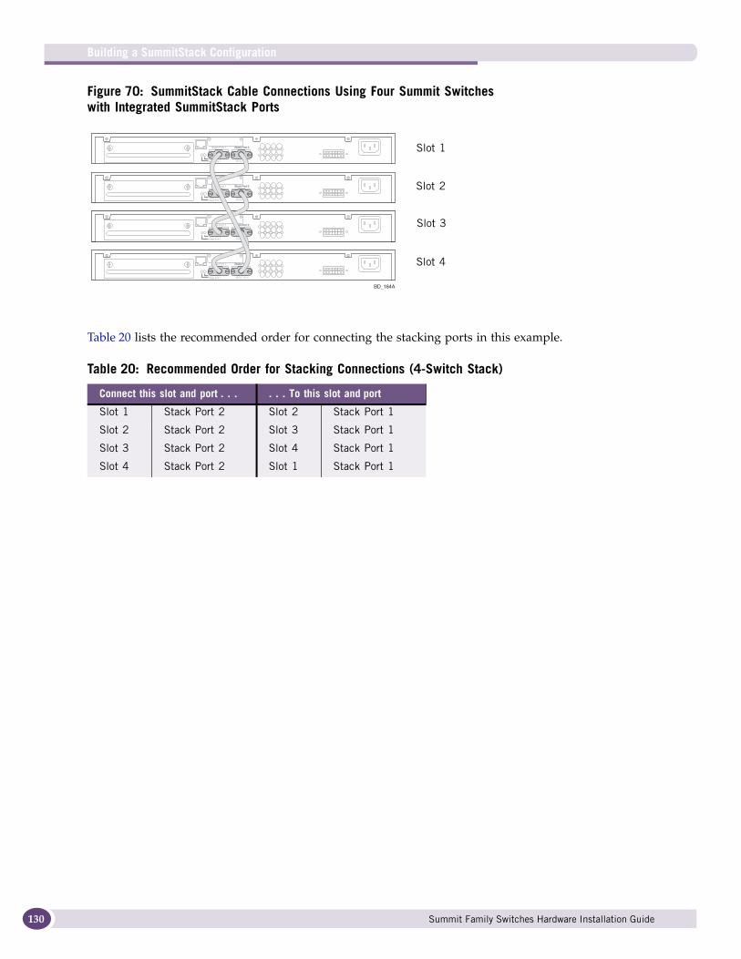
Building a SummitStack Configuration
130
Figure 70: SummitStack Cable Connections Using Four Summit Switches with Integrated SummitStack Ports
Table 20 lists the recommended order for connecting the stacking ports in this example.
Table 20: Recommended Order for Stacking Connections (4-Switch Stack)
Connect this slot and port . . . . . . To this slot and port
Slot 1 Stack Port 2 Slot 2 Stack Port 1
Slot 2 Stack Port 2 Slot 3 Stack Port 1
Slot 3 Stack Port 2 Slot 4 Stack Port 1
Slot 4 Stack Port 2 Slot 1 Stack Port 1
BD_164A
Slot 1
Slot 2
Slot 3
Slot 4
Summit Family Switches Hardware Installation Guide
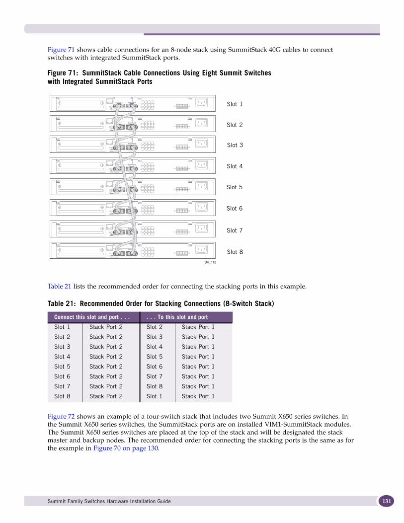
Figure 71 shows cable connections for an 8-node stack using SummitStack 40G cables to connect switches with integrated SummitStack ports.
Figure 71: SummitStack Cable Connections Using Eight Summit Switches with Integrated SummitStack Ports
Table 21 lists the recommended order for connecting the stacking ports in this example.
Figure 72 shows an example of a four-switch stack that includes two Summit X650 series switches. In the Summit X650 series switches, the SummitStack ports are on installed VIM1-SummitStack modules. The Summit X650 series switches are placed at the top of the stack and will be designated the stack master and backup nodes. The recommended order for connecting the stacking ports is the same as for the example in Figure 70 on page 130.
Table 21: Recommended Order for Stacking Connections (8-Switch Stack)
Connect this slot and port . . . . . . To this slot and port
Slot 1 Stack Port 2 Slot 2 Stack Port 1
Slot 2 Stack Port 2 Slot 3 Stack Port 1
Slot 3 Stack Port 2 Slot 4 Stack Port 1
Slot 4 Stack Port 2 Slot 5 Stack Port 1
Slot 5 Stack Port 2 Slot 6 Stack Port 1
Slot 6 Stack Port 2 Slot 7 Stack Port 1
Slot 7 Stack Port 2 Slot 8 Stack Port 1
Slot 8 Stack Port 2 Slot 1 Stack Port 1
SH_175
Slot 1
Slot 2
Slot 3
Slot 4
Slot 5
Slot 6
Slot 7
Slot 8
Summit Family Switches Hardware Installation Guide 131
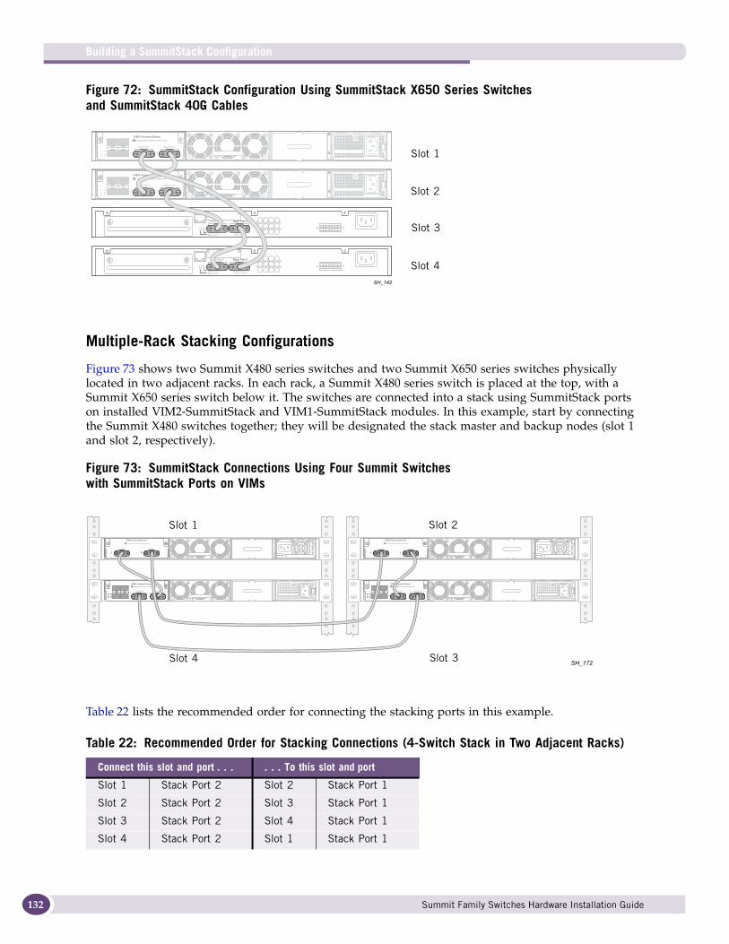
Building a SummitStack Configuration
132
Figure 72: SummitStack Configuration Using SummitStack X650 Series Switches and SummitStack 40G Cables
Multiple-Rack Stacking Configurations
Figure 73 shows two Summit X480 series switches and two Summit X650 series switches physically located in two adjacent racks. In each rack, a Summit X480 series switch is placed at the top, with a Summit X650 series switch below it. The switches are connected into a stack using SummitStack ports on installed VIM2-SummitStack and VIM1-SummitStack modules. In this example, start by connecting the Summit X480 switches together; they will be designated the stack master and backup nodes (slot 1 and slot 2, respectively).
Figure 73: SummitStack Connections Using Four Summit Switcheswith SummitStack Ports on VIMs
Table 22 lists the recommended order for connecting the stacking ports in this example.
Table 22: Recommended Order for Stacking Connections (4-Switch Stack in Two Adjacent Racks)
Connect this slot and port . . . . . . To this slot and port
Slot 1 Stack Port 2 Slot 2 Stack Port 1
Slot 2 Stack Port 2 Slot 3 Stack Port 1
Slot 3 Stack Port 2 Slot 4 Stack Port 1
Slot 4 Stack Port 2 Slot 1 Stack Port 1
SH_142
Slot 1
Slot 2
Slot 3
Slot 4
SH_172
Slot 1 Slot 2
Slot 3Slot 4
Summit Family Switches Hardware Installation Guide
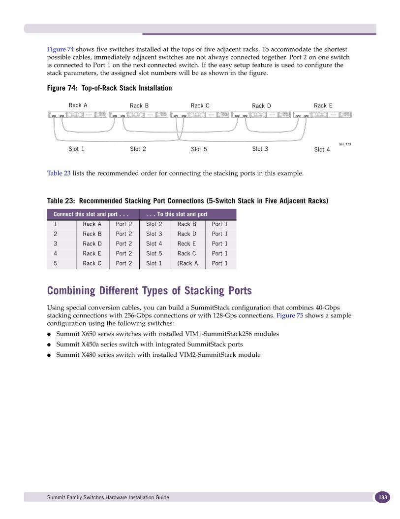
Figure 74 shows five switches installed at the tops of five adjacent racks. To accommodate the shortest possible cables, immediately adjacent switches are not always connected together. Port 2 on one switch is connected to Port 1 on the next connected switch. If the easy setup feature is used to configure the stack parameters, the assigned slot numbers will be as shown in the figure.
Figure 74: Top-of-Rack Stack Installation
Table 23 lists the recommended order for connecting the stacking ports in this example.
Combining Different Types of Stacking PortsUsing special conversion cables, you can build a SummitStack configuration that combines 40-Gbps stacking connections with 256-Gbps connections or with 128-Gps connections. Figure 75 shows a sample configuration using the following switches:
● Summit X650 series switches with installed VIM1-SummitStack256 modules
● Summit X450a series switch with integrated SummitStack ports
● Summit X480 series switch with installed VIM2-SummitStack module
Table 23: Recommended Stacking Port Connections (5-Switch Stack in Five Adjacent Racks)
Connect this slot and port . . . . . . To this slot and port
1 Rack A Port 2 Slot 2 Rack B Port 1
2 Rack B Port 2 Slot 3 Rack D Port 1
3 Rack D Port 2 Slot 4 Reck E Port 1
4 Rack E Port 2 Slot 5 Rack C Port 1
5 Rack C Port 2 Slot 1 (Rack A Port 1
SH_173
Rack A Rack B Rack D Rack ERack C
Slot 1 Slot 2 Slot 3 Slot 4Slot 5
Summit Family Switches Hardware Installation Guide 133
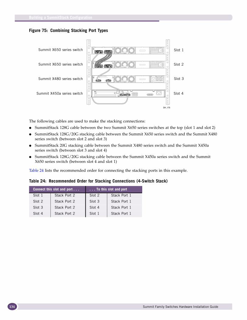
Building a SummitStack Configuration
134
Figure 75: Combining Stacking Port Types
The following cables are used to make the stacking connections:
● SummitStack 128G cable between the two Summit X650 series switches at the top (slot 1 and slot 2)
● SummitStack 128G/20G stacking cable between the Summit X650 series switch and the Summit X480 series switch (between slot 2 and slot 3)
● SummitStack 20G stacking cable between the Summit X480 series switch and the Summit X450a series switch (between slot 3 and slot 4)
● SummitStack 128G/20G stacking cable between the Summit X450a series switch and the Summit X650 series switch (between slot 4 and slot 1)
Table 24 lists the recommended order for connecting the stacking ports in this example.
Table 24: Recommended Order for Stacking Connections (4-Switch Stack)
Connect this slot and port . . . . . . To this slot and port
Slot 1 Stack Port 2 Slot 2 Stack Port 1
Slot 2 Stack Port 2 Slot 3 Stack Port 1
Slot 3 Stack Port 2 Slot 4 Stack Port 1
Slot 4 Stack Port 2 Slot 1 Stack Port 1
SH_175
Slot 1
Slot 4
Slot 2
Slot 3Summit X480 series switch
Summit X650 series switch
Summit X650 series switch
Summit X450a series switch
Summit Family Switches Hardware Installation Guide
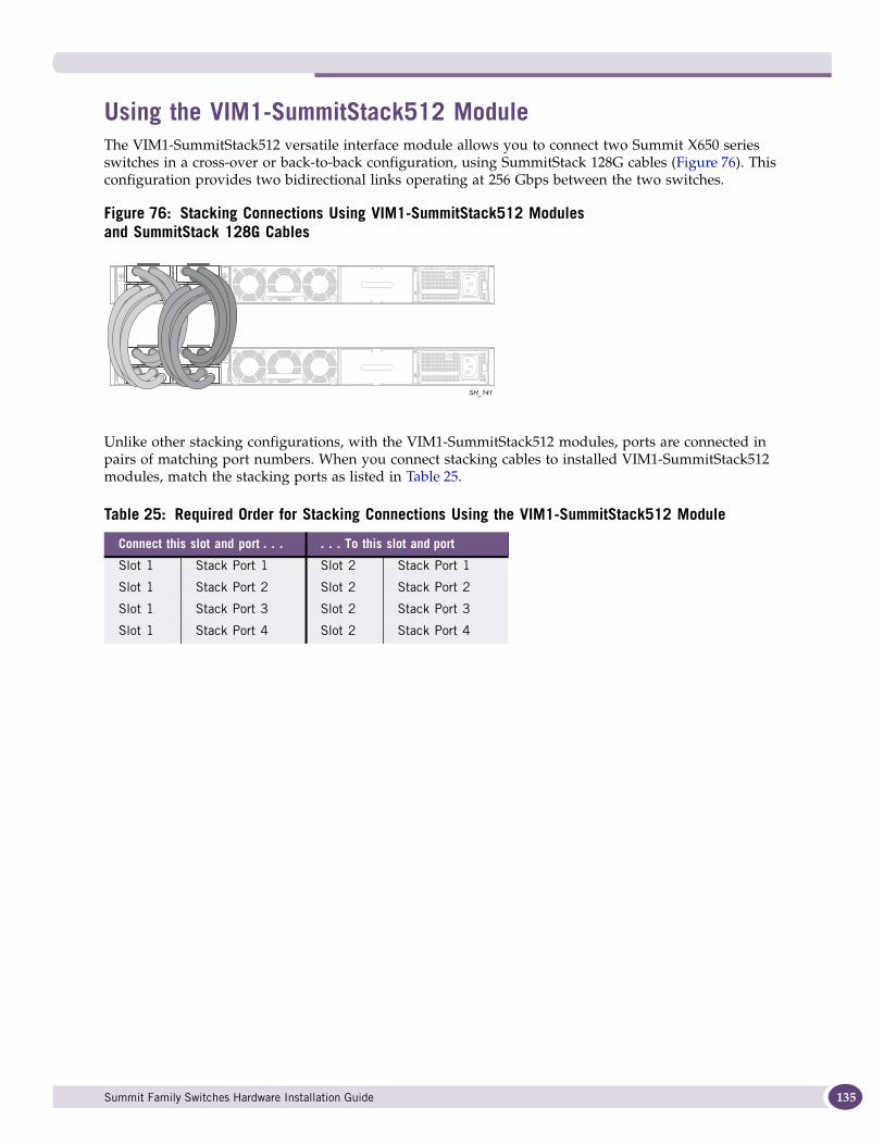
Using the VIM1-SummitStack512 ModuleThe VIM1-SummitStack512 versatile interface module allows you to connect two Summit X650 series switches in a cross-over or back-to-back configuration, using SummitStack 128G cables (Figure 76). This configuration provides two bidirectional links operating at 256 Gbps between the two switches.
Figure 76: Stacking Connections Using VIM1-SummitStack512 Modules and SummitStack 128G Cables
Unlike other stacking configurations, with the VIM1-SummitStack512 modules, ports are connected in pairs of matching port numbers. When you connect stacking cables to installed VIM1-SummitStack512 modules, match the stacking ports as listed in Table 25.
Table 25: Required Order for Stacking Connections Using the VIM1-SummitStack512 Module
Connect this slot and port . . . . . . To this slot and port
Slot 1 Stack Port 1 Slot 2 Stack Port 1
Slot 1 Stack Port 2 Slot 2 Stack Port 2
Slot 1 Stack Port 3 Slot 2 Stack Port 3
Slot 1 Stack Port 4 Slot 2 Stack Port 4
SH_141
Summit Family Switches Hardware Installation Guide 135
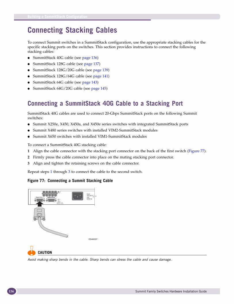
Building a SummitStack Configuration
136
Connecting Stacking CablesTo connect Summit switches in a SummitStack configuration, use the appropriate stacking cables for the specific stacking ports on the switches. This section provides instructions to connect the following stacking cables:
● SummitStack 40G cable (see page 136)
● SummitStack 128G cable (see page 137)
● SummitStack 128G/20G cable (see page 139)
● SummitStack 128G/64G cable (see page 141)
● SummitStack 64G cable (see page 143)
● SummitStack 64G/20G cable (see page 145)
Connecting a SummitStack 40G Cable to a Stacking PortSummitStack 40G cables are used to connect 20-Gbps SummitStack ports on the following Summit switches:
● Summit X250e, X450, X450a, and X450e series switches with integrated SummitStack ports
● Summit X480 series switches with installed VIM2-SummitStack modules
● Summit X650 switches with installed VIM1-SummitStack modules
To connect a SummitStack 40G stacking cable:
1 Align the cable connector with the stacking port connector on the back of the first switch (Figure 77).
2 Firmly press the cable connector into place on the mating stacking port connector.
3 Align and tighten the retaining screws on the cable connector.
Repeat steps 1 through 3 to connect the cable to the second switch.
Figure 77: Connecting a Summit Stacking Cable
CAUTION
Avoid making sharp bends in the cable. Sharp bends can stress the cable and cause damage.
ES4K037
Summit Family Switches Hardware Installation Guide
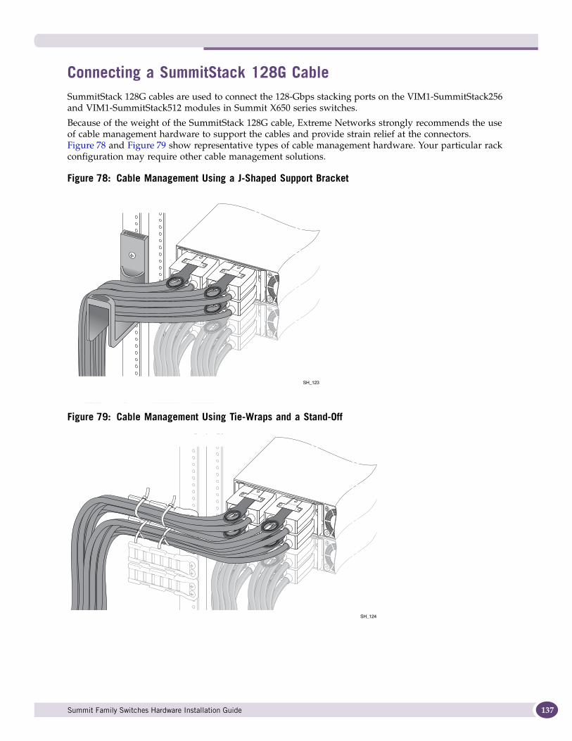
Connecting a SummitStack 128G CableSummitStack 128G cables are used to connect the 128-Gbps stacking ports on the VIM1-SummitStack256 and VIM1-SummitStack512 modules in Summit X650 series switches.
Because of the weight of the SummitStack 128G cable, Extreme Networks strongly recommends the use of cable management hardware to support the cables and provide strain relief at the connectors. Figure 78 and Figure 79 show representative types of cable management hardware. Your particular rack configuration may require other cable management solutions.
Figure 78: Cable Management Using a J-Shaped Support Bracket
Figure 79: Cable Management Using Tie-Wraps and a Stand-Off
SH_123
SH_124
Summit Family Switches Hardware Installation Guide 137
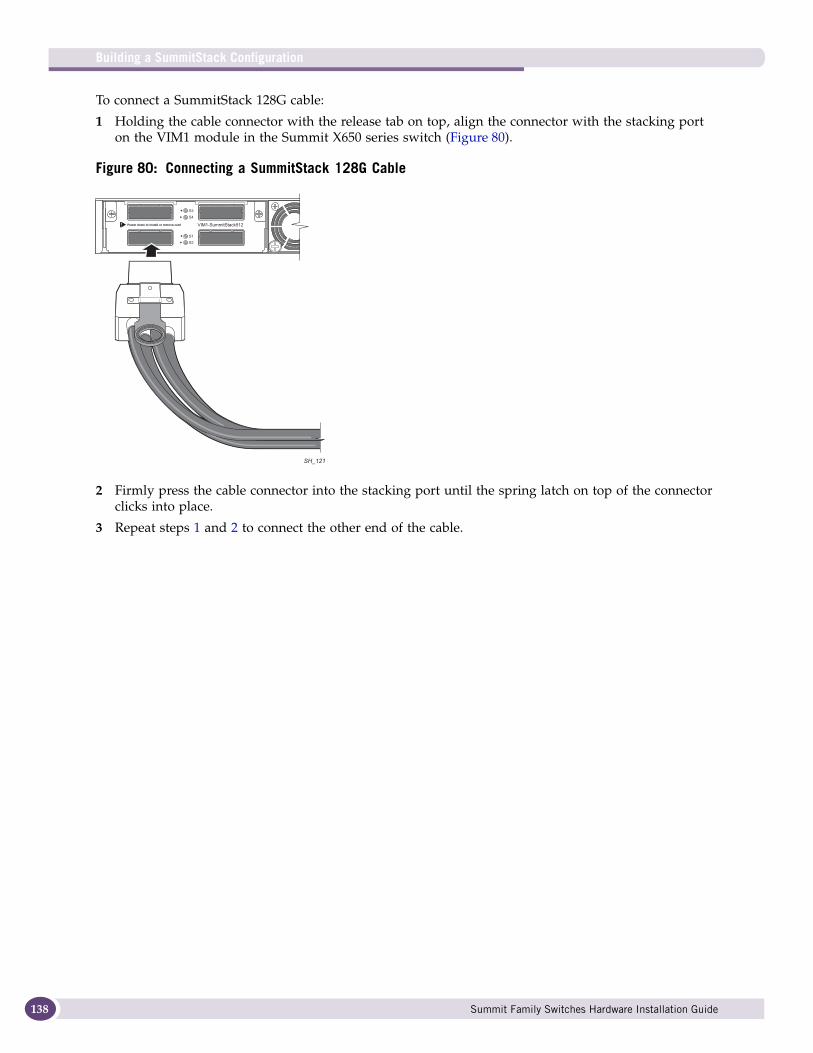
Building a SummitStack Configuration
138
To connect a SummitStack 128G cable:
1 Holding the cable connector with the release tab on top, align the connector with the stacking port on the VIM1 module in the Summit X650 series switch (Figure 80).
Figure 80: Connecting a SummitStack 128G Cable
2 Firmly press the cable connector into the stacking port until the spring latch on top of the connector clicks into place.
3 Repeat steps 1 and 2 to connect the other end of the cable.
SH_121
Summit Family Switches Hardware Installation Guide
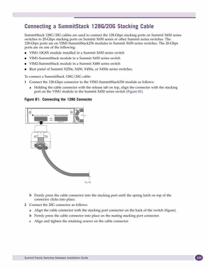
Connecting a SummitStack 128G/20G Stacking CableSummitStack 128G/20G cables are used to connect the 128-Gbps stacking ports on Summit X650 series switches to 20-Gbps stacking ports on Summit X650 series or other Summit series switches. The 128-Gbps ports are on VIM1-SummitStack256 modules in Summit X650 series switches. The 20-Gbps ports are on one of the following:
● VIM1-10G8X module installed in a Summit X650 series switch
● VIM1-SummitStack module in a Summit X650 series switch
● VIM2-SummitStack module in a Summit X480 series switch
● Rear panel of Summit X250e, X450, X450a, or X450e series switches.
To connect a SummitStack 128G/20G cable:
1 Connect the 128-Gbps connector to the VIM1-SummitStack256 module as follows:
a Holding the cable connector with the release tab on top, align the connector with the stacking port on the VIM1 module in the Summit X650 series switch (Figure 81).
Figure 81: Connecting the 128G Connector
b Firmly press the cable connector into the stacking port until the spring latch on top of the connector clicks into place.
2 Connect the 20G connector as follows:
a Align the cable connector with the stacking port connector on the back of the switch (figure).
b Firmly press the cable connector into place on the mating stacking port connector.
c Align and tighten the retaining screws on the cable connector.
SH_149
Summit Family Switches Hardware Installation Guide 139
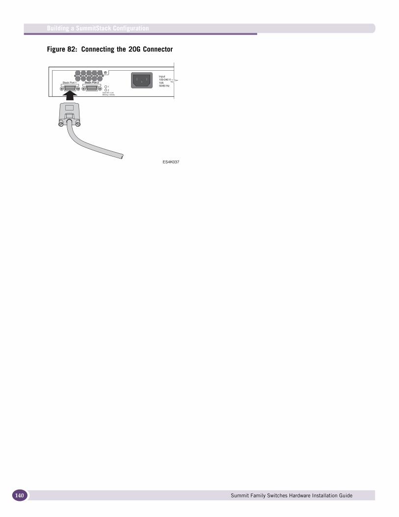
Building a SummitStack Configuration
140
Figure 82: Connecting the 20G Connector
ES4K037
Summit Family Switches Hardware Installation Guide
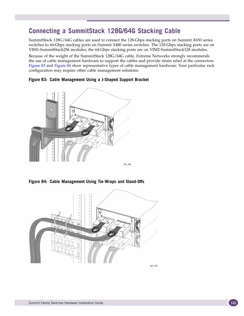
Connecting a SummitStack 128G/64G Stacking CableSummitStack 128G/64G cables are used to connect the 128-Gbps stacking ports on Summit X650 series switches to 64-Gbps stacking ports on Summit X480 series switches. The 128-Gbps stacking ports are on VIM1-SummitStack256 modules; the 64-Gbps stacking ports are on VIM2-SummitStack128 modules.
Because of the weight of the SummitStack 128G/64G cable, Extreme Networks strongly recommends the use of cable management hardware to support the cables and provide strain relief at the connectors. Figure 83 and Figure 84 show representative types of cable management hardware. Your particular rack configuration may require other cable management solutions.
Figure 83: Cable Management Using a J-Shaped Support Bracket
Figure 84: Cable Management Using Tie-Wraps and Stand-Offs
SH_169
SH_170
Summit Family Switches Hardware Installation Guide 141
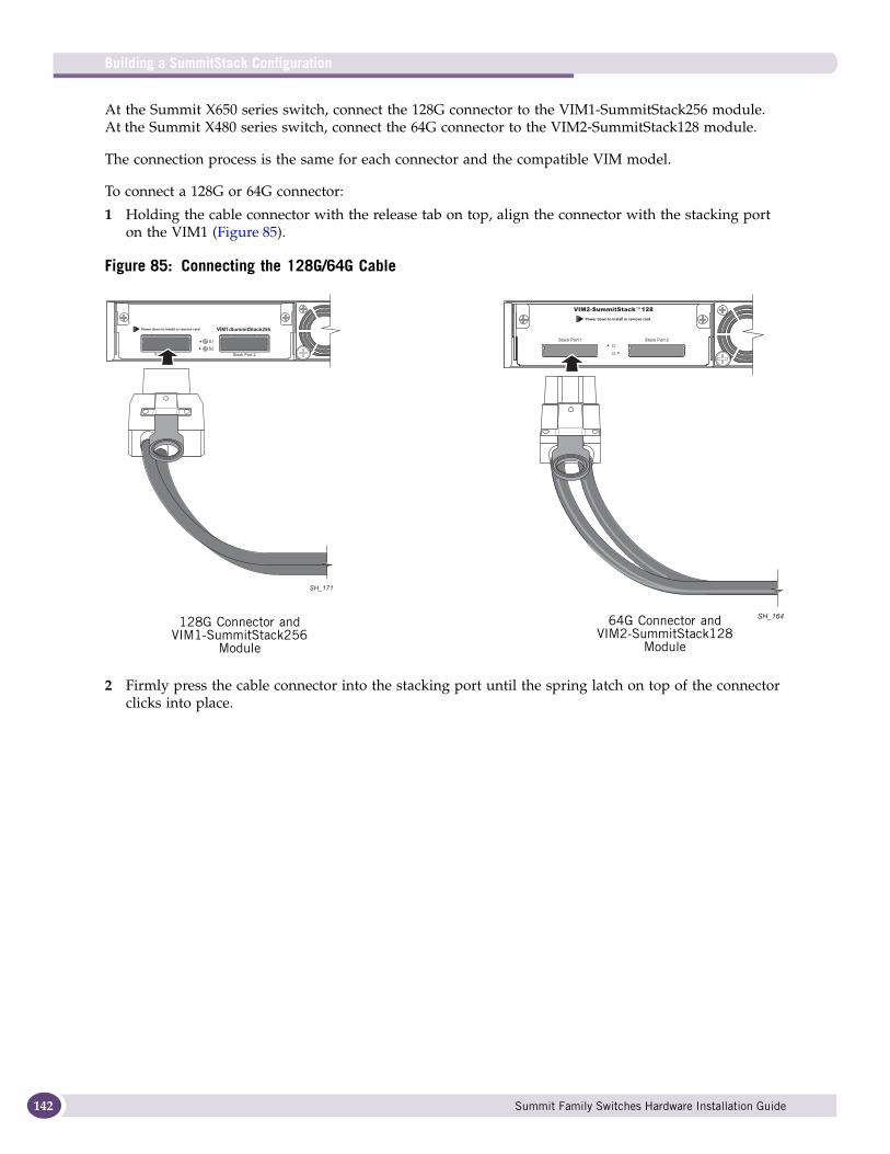
Building a SummitStack Configuration
142
At the Summit X650 series switch, connect the 128G connector to the VIM1-SummitStack256 module. At the Summit X480 series switch, connect the 64G connector to the VIM2-SummitStack128 module.
The connection process is the same for each connector and the compatible VIM model.
To connect a 128G or 64G connector:
1 Holding the cable connector with the release tab on top, align the connector with the stacking port on the VIM1 (Figure 85).
Figure 85: Connecting the 128G/64G Cable
2 Firmly press the cable connector into the stacking port until the spring latch on top of the connector clicks into place.
SH_171
SH_164128G Connector and VIM1-SummitStack256
Module
64G Connector and VIM2-SummitStack128
Module
Summit Family Switches Hardware Installation Guide
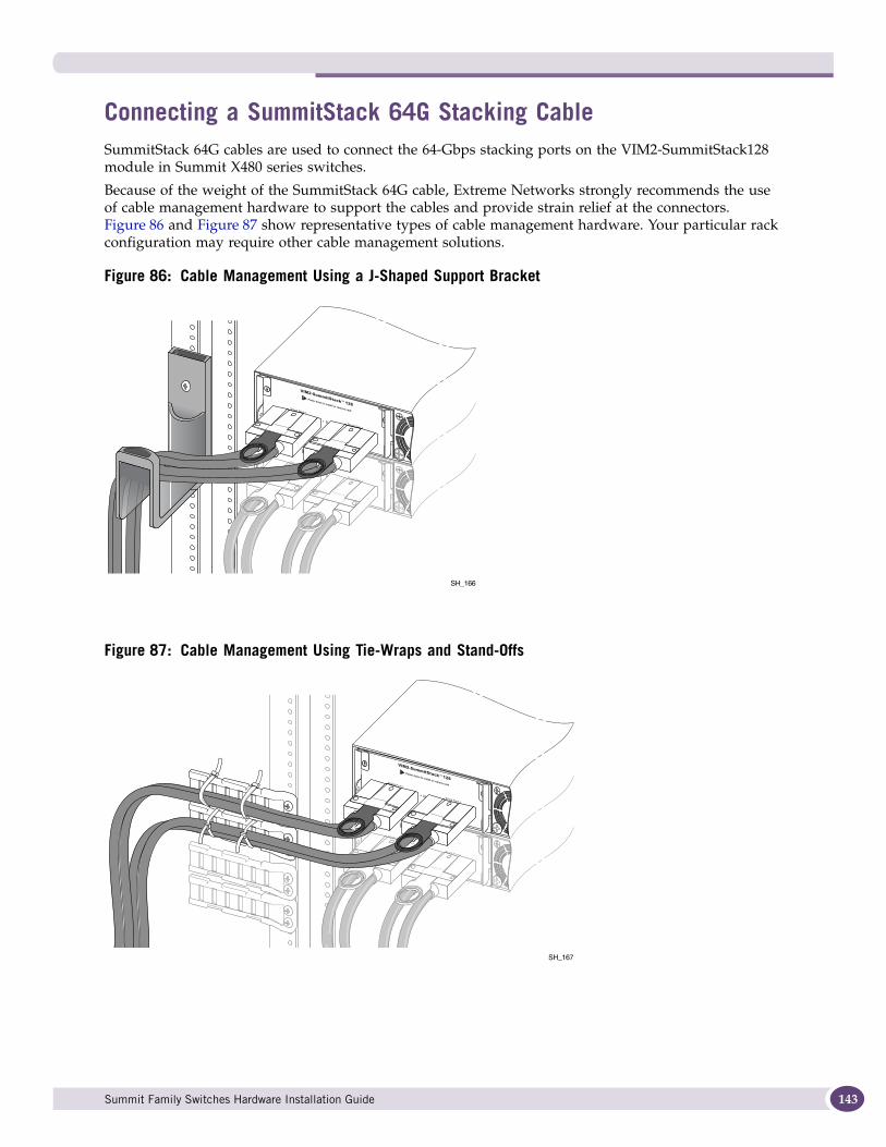
Connecting a SummitStack 64G Stacking CableSummitStack 64G cables are used to connect the 64-Gbps stacking ports on the VIM2-SummitStack128 module in Summit X480 series switches.
Because of the weight of the SummitStack 64G cable, Extreme Networks strongly recommends the use of cable management hardware to support the cables and provide strain relief at the connectors. Figure 86 and Figure 87 show representative types of cable management hardware. Your particular rack configuration may require other cable management solutions.
Figure 86: Cable Management Using a J-Shaped Support Bracket
Figure 87: Cable Management Using Tie-Wraps and Stand-Offs
SH_166
SH_167
Summit Family Switches Hardware Installation Guide 143
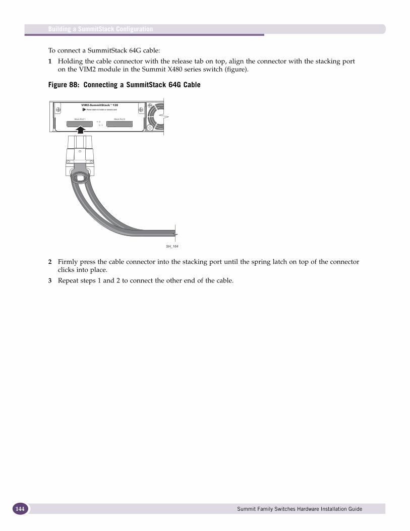
Building a SummitStack Configuration
144
To connect a SummitStack 64G cable:
1 Holding the cable connector with the release tab on top, align the connector with the stacking port on the VIM2 module in the Summit X480 series switch (figure).
Figure 88: Connecting a SummitStack 64G Cable
2 Firmly press the cable connector into the stacking port until the spring latch on top of the connector clicks into place.
3 Repeat steps 1 and 2 to connect the other end of the cable.
SH_164
Summit Family Switches Hardware Installation Guide
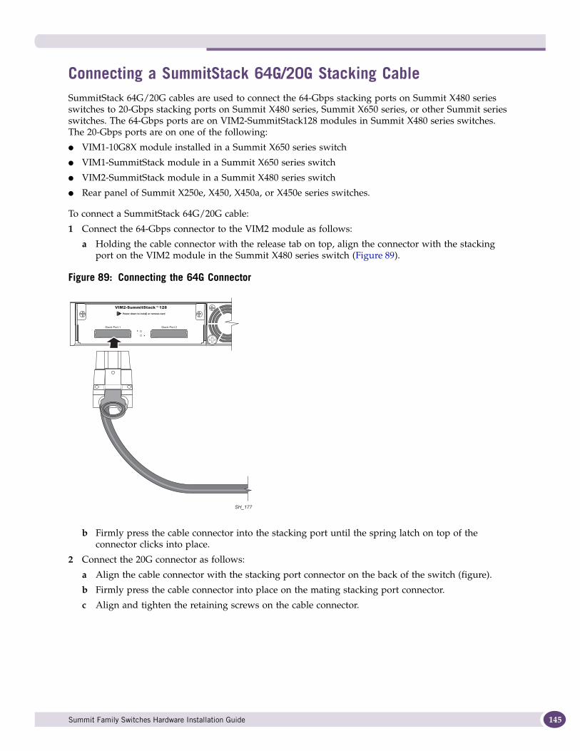
Connecting a SummitStack 64G/20G Stacking CableSummitStack 64G/20G cables are used to connect the 64-Gbps stacking ports on Summit X480 series switches to 20-Gbps stacking ports on Summit X480 series, Summit X650 series, or other Summit series switches. The 64-Gbps ports are on VIM2-SummitStack128 modules in Summit X480 series switches. The 20-Gbps ports are on one of the following:
● VIM1-10G8X module installed in a Summit X650 series switch
● VIM1-SummitStack module in a Summit X650 series switch
● VIM2-SummitStack module in a Summit X480 series switch
● Rear panel of Summit X250e, X450, X450a, or X450e series switches.
To connect a SummitStack 64G/20G cable:
1 Connect the 64-Gbps connector to the VIM2 module as follows:
a Holding the cable connector with the release tab on top, align the connector with the stacking port on the VIM2 module in the Summit X480 series switch (Figure 89).
Figure 89: Connecting the 64G Connector
b Firmly press the cable connector into the stacking port until the spring latch on top of the connector clicks into place.
2 Connect the 20G connector as follows:
a Align the cable connector with the stacking port connector on the back of the switch (figure).
b Firmly press the cable connector into place on the mating stacking port connector.
c Align and tighten the retaining screws on the cable connector.
SH_177
Summit Family Switches Hardware Installation Guide 145
Building a SummitStack Configuration
146
Connecting Console Ports for a StackTo begin the software configuration for a new stack, you must have at least one console port connected. Connect a console to the console port of the switch that you intend to become the master of the stack. If you are going to configure redundancy, you may wish to connect to the console ports of all switches in the stack that you will configure to be master-capable. If you followed the cabling examples in “Connecting the Switches to Form the Stack Ring” on page 129, and you use the easy-setup configuration procedure, only slots 1 and 2 will be allowed to become master.
Management Port CablingConnect the master, backup, and all other master-capable switches to your management network using the Ethernet management port on the rear panel of each switch. If you choose the default redundancy setup, only slots 1 and 2 are allowed to become master. You may connect all switch management ports in the stack if you choose to do so. There is an alternate IP address configuration that will allow you to directly log into an individual switch in the stack through its management port.
Stacking Port LEDsEach stacking port has an LED. The LED is steady green if the link is OK, blinking green if traffic is present, and off if no signal is present.
Summit Family Switches Hardware Installation Guide
5 Installing Summit Family Switches
This chapter describes how to install and remove Summit family switches and associated components. The chapter also includes information about connecting network interface cables and establishing management access.
If you intend to use the SummitStack feature, see Chapter 4 before you install the switches. Chapter 4 provides information about locating stacked switches and connecting the stacking cables.
This chapter includes the following topics:
● Safety Information on page 147
● Installing a Summit Family Switch (Models Other than Summit X480 and X650 Series) on page 148
● Installing and Removing Summit DC-Powered Switches on page 150
● Installing a Summit X480 Series Switch on page 155
● Installing Summit X480 Power Supplies on page 162
● Removing a Summit X480 Series Switch on page 171
● Installing a Summit X650 Series Switch on page 177
● Installing Summit X650 Power Supplies on page 184
● Removing a Summit X650 Series Switch on page 192
● Connecting Network Interface Cables on page 197
● Initial Management Access on page 198
Safety InformationRead the information in this chapter thoroughly before you attempt to install or remove a Summit switch.
NOTE
See Appendix A, “Safety Information” for additional safety information and Appendix B, “Technical Specifications” for additional information regarding regulatory compliance certifications.
CAUTION
Be sure that proper ESD controls are in use before switch maintenance is performed. This includes but is not limited to wrist straps that are grounded to the switch chassis and earth grounds.
WARNING!
Be sure to connect the chassis ground wire before you connect any DC power cables. Be sure to disconnect the ground wire after you disconnect all DC power cables.
Summit Family Switches Hardware Installation Guide 147
Installing Summit Family Switches
148
Installing a Summit Family Switch (Models Other than Summit X480 and X650 Series)This section describes how to install the following Summit family switches:
● Summit X150 series
● Summit X250e series
● Summit X350 series
● Summit X450 series
● Summit X450a series
● Summit X450e series
For instructions to install the Summit X480 series switches, see “Installing a Summit X480 Series Switch” on page 155.
For instructions to install the Summit X650 series switches, see “Installing a Summit X650 Series Switch” on page 177.
A Summit family switch can be mounted in a standard 19-inch (48.26 cm) rack or placed free-standing on a tabletop. The installation process includes the following tasks:
1 Install the switch in a rack or on a table.
2 Ground the switch (DC-powered units only).
3 Connect a redundant power supply (if applicable).
4 Connect power cables.
5 Connect network interface cables.
If you are installing Summit family switches for use in a SummitStack configuration, read Chapter 2, “Building a SummitStack Configuration,” before you install the switches.
For information about grounding and connecting DC-powered Summit family switches, see “Installing and Removing Summit DC-Powered Switches” on page 150.
For information about installing and connecting redundant power supplies, see Chapter 6, “Installing Summit External Power Supplies.”
Rack-Mounting a Summit Switch (Models Other than Summit X480 and X650 Series)This section describes how to install Summit switches in the following series:
● Summit X150
● Summit X250e
● Summit X350
● Summit X450
● Summit X450a
● Summit X450e
Summit Family Switches Hardware Installation Guide
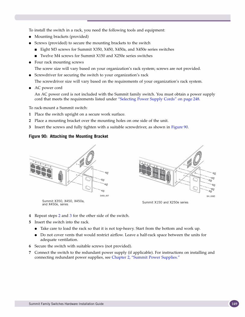
To install the switch in a rack, you need the following tools and equipment:
● Mounting brackets (provided)
● Screws (provided) to secure the mounting brackets to the switch
■ Eight M3 screws for Summit X350, X450, X450a, and X450e series switches
■ Twelve M4 screws for Summit X150 and X250e series switches
● Four rack mounting screws
The screw size will vary based on your organization’s rack system; screws are not provided.
● Screwdriver for securing the switch to your organization’s rack
The screwdriver size will vary based on the requirements of your organization’s rack system.
● AC power cord
An AC power cord is not included with the Summit family switch. You must obtain a power supply cord that meets the requirements listed under “Selecting Power Supply Cords” on page 248.
To rack-mount a Summit switch:
1 Place the switch upright on a secure work surface.
2 Place a mounting bracket over the mounting holes on one side of the unit.
3 Insert the screws and fully tighten with a suitable screwdriver, as shown in Figure 90.
Figure 90: Attaching the Mounting Bracket
4 Repeat steps 2 and 3 for the other side of the switch.
5 Insert the switch into the rack.
● Take care to load the rack so that it is not top-heavy. Start from the bottom and work up.
● Do not cover vents that would restrict airflow. Leave a half-rack space between the units for adequate ventilation.
6 Secure the switch with suitable screws (not provided).
7 Connect the switch to the redundant power supply (if applicable). For instructions on installing and connecting redundant power supplies, see Chapter 2, “Summit Power Supplies.”
Solid ON = LinkBlinking = Activity
3433
3635
3837
4039
4241
4443
46
84
54
47
46X45X
48X47X
Shared Ports
SH_035bS450_007
Summit X350, X450, X450a, and X450e, series
Summit X150 and X250e series
Summit Family Switches Hardware Installation Guide 149
Installing Summit Family Switches
150
8 Connect the power cables.
● For AC-powered units, connect the power cable to the AC power connector on the back of the switch. Then connect the power cable to an AC power socket.
● For information about DC-powered units, see “Installing and Removing Summit DC-Powered Switches” on page 150.
Free-Standing and Desktop Mounting of Multiple SwitchesSummit family switches are supplied with four self-adhesive rubber pads. Apply the pads to the underside of each device by placing the pad in the marked area at each corner of the switch, ensuring that all corners are aligned. You can safely place up to four Summit family switches on top of one another.
Removing an AC-Powered Summit Switch from a Rack (Models Other than Summit X650 Series)To remove an AC-powered Summit switch from a rack:
1 Remove power from the switch.
Unplug the power cables from the from the wall outlets first and then from the switch.
2 Disconnect the Summit switch from the redundant power supply (if applicable).
3 Loosen and remove the four screws holding the switch in place in the system rack.
4 Carefully remove the switch from the rack and place it on a secure, flat surface.
NOTE
For information about DC-powered units, see “Removing a Summit DC-Powered Switch from a Rack” on page 154.
For information about removing a Summit X650 series switch from a rack, see “Removing a Summit X650 Series Switch from a Two-Post Rack” on page 194.
Installing and Removing Summit DC-Powered SwitchesThis section provides additional details about installing or removing the following Summit DC-powered switches:
● Summit X250e-24tDC
● Summit X250e-24xDC
● Summit X250e-48tDC
● Summit X450a-24tDC
● Summit X450a-24xDC
● Summit X450a-48tDC
You must adhere to specific safety requirements when you connect or disconnect a DC power source for one of these Summit switches.
Summit Family Switches Hardware Installation Guide
NOTE
For centralized DC power connection, these products are intended to be installed in Restricted Access Locations (Dedicated Equipment Rooms, Equipment Closets, or the like) in accordance with Articles 110-16, 110-17, and 110-18 of the National Electric Code, ANSI/NFPA 70.
NOTE
An optional redundant power supply, the EPS-150DC, is available for use with the Summit DC-powered switches. When the EPS-150DC is used with a DC-powered Summit switch, the power supplies (internal and redundant) are fully fault tolerant and load-sharing. If one power supply fails, the other power supply will provide sufficient power to operate the switch. Refer to “EPS-150DC External Power Module (with EPS-T2)” on page 104 for further details.
Connecting the Internal DC Power Supply to the DC Source VoltageBefore you connect the switch to a power source, complete the physical installation of the switch in the equipment rack, as described in “Rack-Mounting a Summit Switch (Models Other than Summit X480 and X650 Series)” on page 148.
If you are installing a Summit DC-powered switch, you must ground the chassis before connecting the switch to the DC source voltage (see “Grounding a Summit DC-Powered Switch” below).
Grounding a Summit DC-Powered SwitchBefore you connect the power input cable to a Summit DC-powered switch, you must ground the chassis, following the instructions in this section.
Gather the following materials to ground the Summit DC-powered switch:
● Stranded copper wire cable, minimum size 14 AWG, maximum size 6 AWG
The wire should be long enough to reach from the installed switch to the facility ground point
● Torque screwdriver with 1/4-inch flat blade
● Additional grounding hardware appropriate to the earth ground connection at your site
WARNING!
Be sure to connect the chassis ground wire before you connect any power cables.
To ground the switch:
1 At one end of the wire, strip the insulation to expose 1/2 inch (12 mm) of bare wire.
2 Identify the grounding lug on the back of the switch. The grounding lug is next to the edge of the back panel, identified by the international symbol for earth ground. Depending on the switch model, the grounding lug may be on either side (see Figure 91).
Summit Family Switches Hardware Installation Guide 151
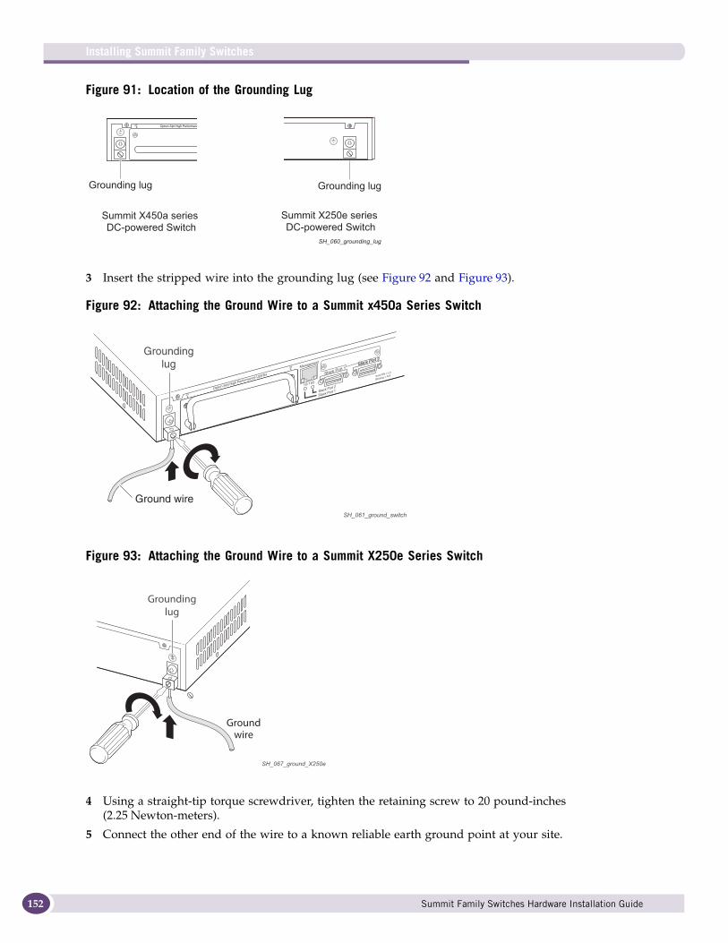
Installing Summit Family Switches
152
Figure 91: Location of the Grounding Lug
3 Insert the stripped wire into the grounding lug (see Figure 92 and Figure 93).
Figure 92: Attaching the Ground Wire to a Summit x450a Series Switch
Figure 93: Attaching the Ground Wire to a Summit X250e Series Switch
4 Using a straight-tip torque screwdriver, tighten the retaining screw to 20 pound-inches (2.25 Newton-meters).
5 Connect the other end of the wire to a known reliable earth ground point at your site.
Summit X250e series DC-powered Switch
Grounding lug
Summit X450a series DC-powered Switch
Grounding lug
SH_060_grounding_lug
SH_061_ground_switch
Groundinglug
Ground wire
SH_067_ground_X250e
Groundinglug
Groundwire
Summit Family Switches Hardware Installation Guide
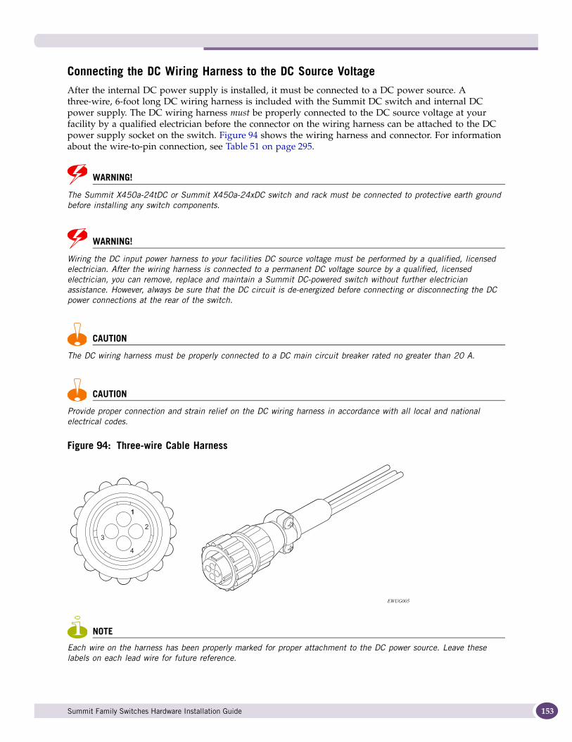
Connecting the DC Wiring Harness to the DC Source VoltageAfter the internal DC power supply is installed, it must be connected to a DC power source. A three-wire, 6-foot long DC wiring harness is included with the Summit DC switch and internal DC power supply. The DC wiring harness must be properly connected to the DC source voltage at your facility by a qualified electrician before the connector on the wiring harness can be attached to the DC power supply socket on the switch. Figure 94 shows the wiring harness and connector. For information about the wire-to-pin connection, see Table 51 on page 295.
WARNING!
The Summit X450a-24tDC or Summit X450a-24xDC switch and rack must be connected to protective earth ground before installing any switch components.
WARNING!
Wiring the DC input power harness to your facilities DC source voltage must be performed by a qualified, licensed electrician. After the wiring harness is connected to a permanent DC voltage source by a qualified, licensed electrician, you can remove, replace and maintain a Summit DC-powered switch without further electrician assistance. However, always be sure that the DC circuit is de-energized before connecting or disconnecting the DC power connections at the rear of the switch.
CAUTION
The DC wiring harness must be properly connected to a DC main circuit breaker rated no greater than 20 A.
CAUTION
Provide proper connection and strain relief on the DC wiring harness in accordance with all local and national electrical codes.
Figure 94: Three-wire Cable Harness
NOTE
Each wire on the harness has been properly marked for proper attachment to the DC power source. Leave these labels on each lead wire for future reference.
EWUG005
Summit Family Switches Hardware Installation Guide 153
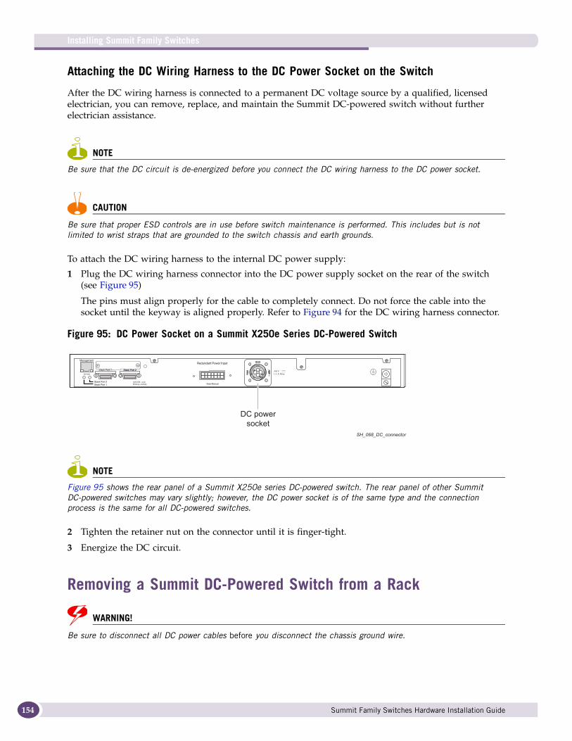
Installing Summit Family Switches
154
Attaching the DC Wiring Harness to the DC Power Socket on the Switch
After the DC wiring harness is connected to a permanent DC voltage source by a qualified, licensed electrician, you can remove, replace, and maintain the Summit DC-powered switch without further electrician assistance.
NOTE
Be sure that the DC circuit is de-energized before you connect the DC wiring harness to the DC power socket.
CAUTION
Be sure that proper ESD controls are in use before switch maintenance is performed. This includes but is not limited to wrist straps that are grounded to the switch chassis and earth grounds.
To attach the DC wiring harness to the internal DC power supply:
1 Plug the DC wiring harness connector into the DC power supply socket on the rear of the switch (see Figure 95)
The pins must align properly for the cable to completely connect. Do not force the cable into the socket until the keyway is aligned properly. Refer to Figure 94 for the DC wiring harness connector.
Figure 95: DC Power Socket on a Summit X250e Series DC-Powered Switch
NOTE
Figure 95 shows the rear panel of a Summit X250e series DC-powered switch. The rear panel of other Summit DC-powered switches may vary slightly; however, the DC power socket is of the same type and the connection process is the same for all DC-powered switches.
2 Tighten the retainer nut on the connector until it is finger-tight.
3 Energize the DC circuit.
Removing a Summit DC-Powered Switch from a Rack
WARNING!
Be sure to disconnect all DC power cables before you disconnect the chassis ground wire.
SH_068_DC_connector
Redundant Power Input
! See Manual
-48 V1.5 A Max
DC powersocket
Summit Family Switches Hardware Installation Guide
CAUTION
Be sure that proper ESD controls are in use before switch maintenance is performed. This includes but is not limited to wrist straps that are grounded to the switch chassis and earth grounds.
To remove a DC-powered Summit switch from an equipment rack:
1 De-energize the DC circuit for all power connections.
2 Loosen the retainer nut and unplug the DC power connector from the DC power socket on the rear of the switch.
3 Disconnect the Summit switch from the redundant power supply (if applicable).
4 At the back of the switch, loosen the retaining screw on the ground lug and pull the ground wire out of the lug. Move the ground wire out of the way.
5 Loosen and remove the four rack system mount screws holding the switch in place against the system rack.
6 Carefully remove the switch from the rack and place it on a secure, flat surface.
WARNING!
Removing the DC wiring harness from your facilities DC source voltage requires the performance of a qualified, licensed electrician.
Installing a Summit X480 Series SwitchThe Summit X480 series switch fits into a standard 19-inch equipment rack. The provided rack-mounting brackets are adaptable to either two-post or four-post mounting.
The installation process includes the following tasks:
1 Install the switch in the rack.
2 Install one or two power supplies and connect power cables.
3 Connect network interface cables.
If you are installing Summit X480 series switches for use in a SummitStack configuration, read Chapter 2, “Building a SummitStack Configuration,” before you install the switches.
NOTE
Take care to load the rack so that it is not top-heavy. Start installing equipment at the bottom and work up.
Pre-installation RequirementsInstalling the Summit X480 switch requires two people to maneuver the switch and attach mounting hardware.
To allow safe handling of the switch during the installation process, make sure you have the following available space around the rack:
● Back: Minimum 30 inches behind the rack posts.
Summit Family Switches Hardware Installation Guide 155
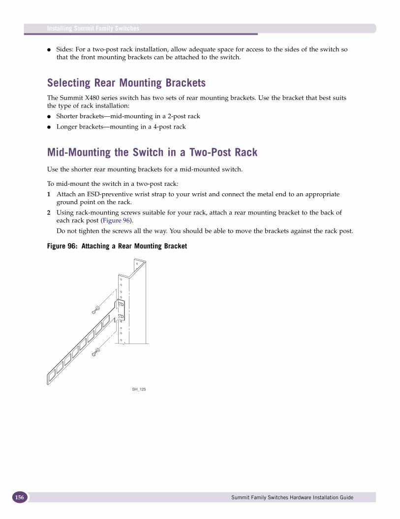
Installing Summit Family Switches
156
● Sides: For a two-post rack installation, allow adequate space for access to the sides of the switch so that the front mounting brackets can be attached to the switch.
Selecting Rear Mounting BracketsThe Summit X480 series switch has two sets of rear mounting brackets. Use the bracket that best suits the type of rack installation:
● Shorter brackets—mid-mounting in a 2-post rack
● Longer brackets—mounting in a 4-post rack
Mid-Mounting the Switch in a Two-Post RackUse the shorter rear mounting brackets for a mid-mounted switch.
To mid-mount the switch in a two-post rack:
1 Attach an ESD-preventive wrist strap to your wrist and connect the metal end to an appropriate ground point on the rack.
2 Using rack-mounting screws suitable for your rack, attach a rear mounting bracket to the back of each rack post (Figure 96).
Do not tighten the screws all the way. You should be able to move the brackets against the rack post.
Figure 96: Attaching a Rear Mounting Bracket
SH_125
Summit Family Switches Hardware Installation Guide
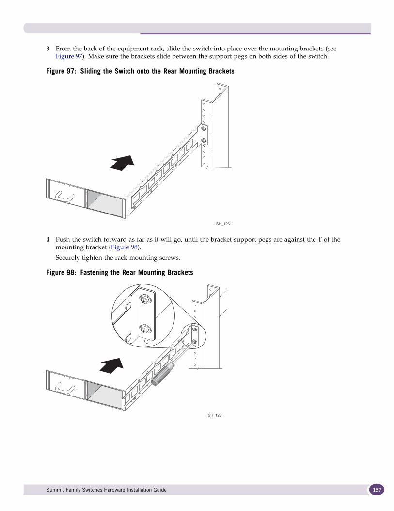
3 From the back of the equipment rack, slide the switch into place over the mounting brackets (see Figure 97). Make sure the brackets slide between the support pegs on both sides of the switch.
Figure 97: Sliding the Switch onto the Rear Mounting Brackets
4 Push the switch forward as far as it will go, until the bracket support pegs are against the T of the mounting bracket (Figure 98).
Securely tighten the rack mounting screws.
Figure 98: Fastening the Rear Mounting Brackets
SH_126
SH_128
Summit Family Switches Hardware Installation Guide 157
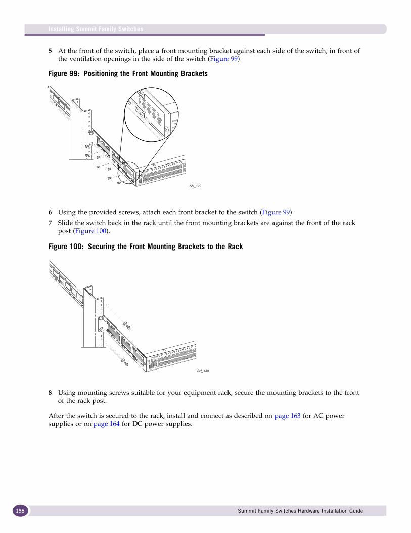
Installing Summit Family Switches
158
5 At the front of the switch, place a front mounting bracket against each side of the switch, in front of the ventilation openings in the side of the switch (Figure 99)
Figure 99: Positioning the Front Mounting Brackets
6 Using the provided screws, attach each front bracket to the switch (Figure 99).
7 Slide the switch back in the rack until the front mounting brackets are against the front of the rack post (Figure 100).
Figure 100: Securing the Front Mounting Brackets to the Rack
8 Using mounting screws suitable for your equipment rack, secure the mounting brackets to the front of the rack post.
After the switch is secured to the rack, install and connect as described on page 163 for AC power supplies or on page 164 for DC power supplies.
SH_129
SH_130
Summit Family Switches Hardware Installation Guide
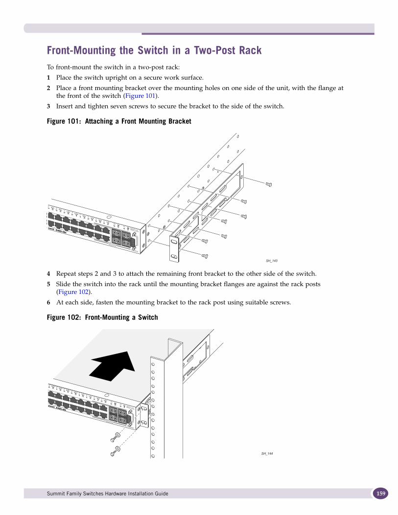
Front-Mounting the Switch in a Two-Post RackTo front-mount the switch in a two-post rack:
1 Place the switch upright on a secure work surface.
2 Place a front mounting bracket over the mounting holes on one side of the unit, with the flange at the front of the switch (Figure 101).
3 Insert and tighten seven screws to secure the bracket to the side of the switch.
Figure 101: Attaching a Front Mounting Bracket
4 Repeat steps 2 and 3 to attach the remaining front bracket to the other side of the switch.
5 Slide the switch into the rack until the mounting bracket flanges are against the rack posts (Figure 102).
6 At each side, fasten the mounting bracket to the rack post using suitable screws.
Figure 102: Front-Mounting a Switch
SH_143
SH_144
Summit Family Switches Hardware Installation Guide 159
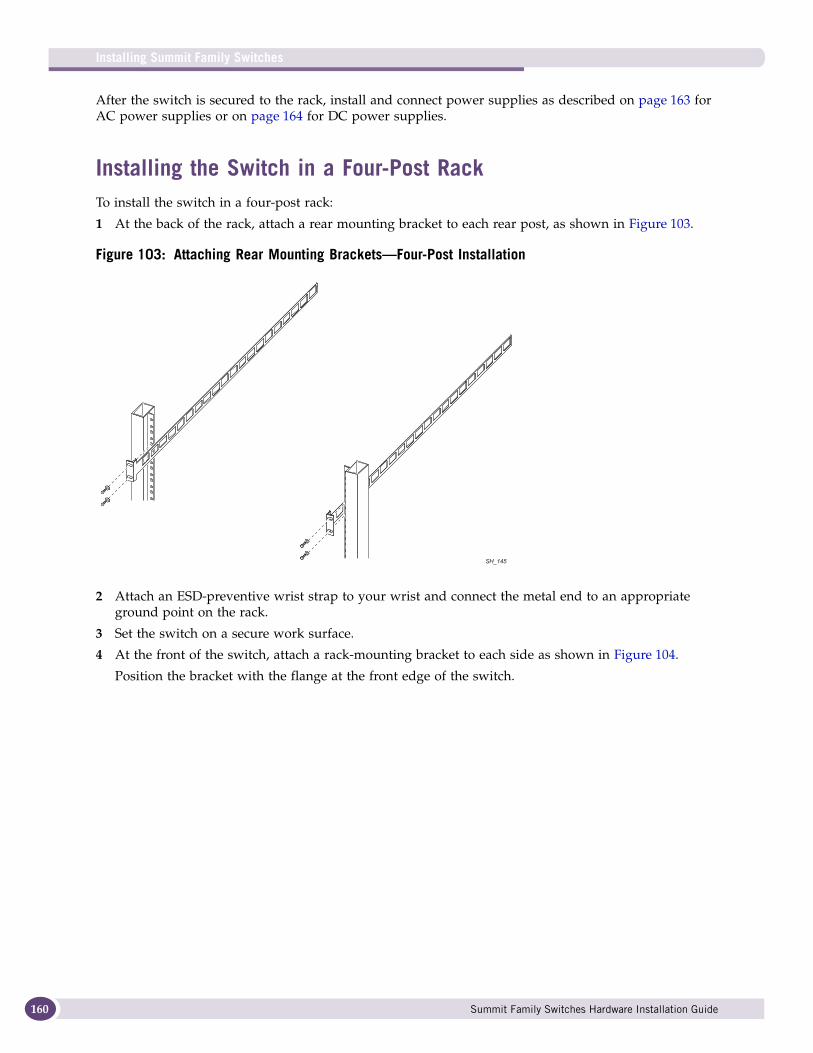
Installing Summit Family Switches
160
After the switch is secured to the rack, install and connect power supplies as described on page 163 for AC power supplies or on page 164 for DC power supplies.
Installing the Switch in a Four-Post RackTo install the switch in a four-post rack:
1 At the back of the rack, attach a rear mounting bracket to each rear post, as shown in Figure 103.
Figure 103: Attaching Rear Mounting Brackets—Four-Post Installation
2 Attach an ESD-preventive wrist strap to your wrist and connect the metal end to an appropriate ground point on the rack.
3 Set the switch on a secure work surface.
4 At the front of the switch, attach a rack-mounting bracket to each side as shown in Figure 104.
Position the bracket with the flange at the front edge of the switch.
SH_145
Summit Family Switches Hardware Installation Guide
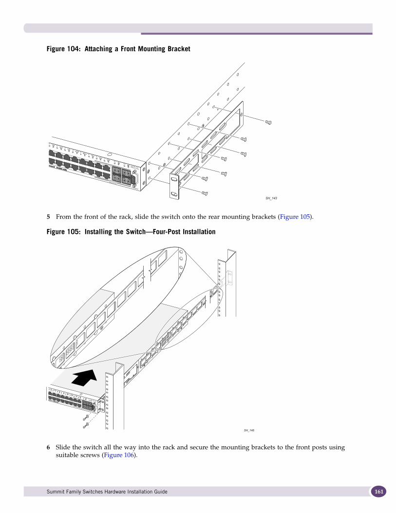
Figure 104: Attaching a Front Mounting Bracket
5 From the front of the rack, slide the switch onto the rear mounting brackets (Figure 105).
Figure 105: Installing the Switch—Four-Post Installation
6 Slide the switch all the way into the rack and secure the mounting brackets to the front posts using suitable screws (Figure 106).
SH_143
SH_146
Summit Family Switches Hardware Installation Guide 161

Installing Summit Family Switches
162
Figure 106: Securing the Switch to the Front Rack Posts—Four-Post Installation
After the switch is secured to the rack, install and connect power supplies as described on page 163 for AC power supplies or on page 164 for DC power supplies.
Installing Summit X480 Power SuppliesThe Summit X480 series switch is shipped without installed power supplies. The switch accommodates one or two Summit X480 power supply units (PSUs).
AC Power Supply CordsAn AC power cord is not included with the Summit X480 AC PSU. AC power cords for use in the US and Canada from Extreme Networks or from your local supplier. The cord must meet the following requirements:
● The power cord must be agency-certified for the country of use and rated for 100-240 V AC.
● The power cord must have an IEC 320 C13 connector for connection to the PSU.
● The power cord must have an appropriately rated and approved wall plug applicable to the country of installation.
● For cords up to 6 feet (2 m) long, the wire size must be 18 AWG (.75 mm2) minimum; over 6 feet, the minimum wire size is 16 AWG (1.0 mm2).
For additional power cord requirements, see “Selecting Power Supply Cords” on page 248.
SH_147
Summit Family Switches Hardware Installation Guide
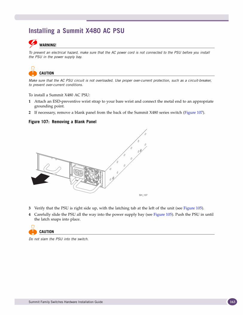
Installing a Summit X480 AC PSU
WARNING!
To prevent an electrical hazard, make sure that the AC power cord is not connected to the PSU before you install the PSU in the power supply bay.
CAUTION
Make sure that the AC PSU circuit is not overloaded. Use proper over-current protection, such as a circuit-breaker, to prevent over-current conditions.
To install a Summit X480 AC PSU:
1 Attach an ESD-preventive wrist strap to your bare wrist and connect the metal end to an appropriate grounding point.
2 If necessary, remove a blank panel from the back of the Summit X480 series switch (Figure 107).
Figure 107: Removing a Blank Panel
3 Verify that the PSU is right side up, with the latching tab at the left of the unit (see Figure 105).
4 Carefully slide the PSU all the way into the power supply bay (see Figure 105). Push the PSU in until the latch snaps into place.
CAUTION
Do not slam the PSU into the switch.
SH_137
Summit Family Switches Hardware Installation Guide 163
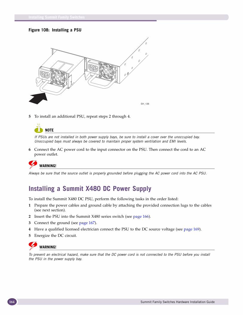
Installing Summit Family Switches
164
Figure 108: Installing a PSU
5 To install an additional PSU, repeat steps 2 through 4.
NOTE
If PSUs are not installed in both power supply bays, be sure to install a cover over the unoccupied bay. Unoccupied bays must always be covered to maintain proper system ventilation and EMI levels.
6 Connect the AC power cord to the input connector on the PSU. Then connect the cord to an AC power outlet.
WARNING!
Always be sure that the source outlet is properly grounded before plugging the AC power cord into the AC PSU.
Installing a Summit X480 DC Power SupplyTo install the Summit X480 DC PSU, perform the following tasks in the order listed:
1 Prepare the power cables and ground cable by attaching the provided connection lugs to the cables (see next section).
2 Insert the PSU into the Summit X480 series switch (see page 166).
3 Connect the ground (see page 167).
4 Have a qualified licensed electrician connect the PSU to the DC source voltage (see page 169).
5 Energize the DC circuit.
WARNING!
To prevent an electrical hazard, make sure that the DC power cord is not connected to the PSU before you install the PSU in the power supply bay.
SH_138
Summit Family Switches Hardware Installation Guide
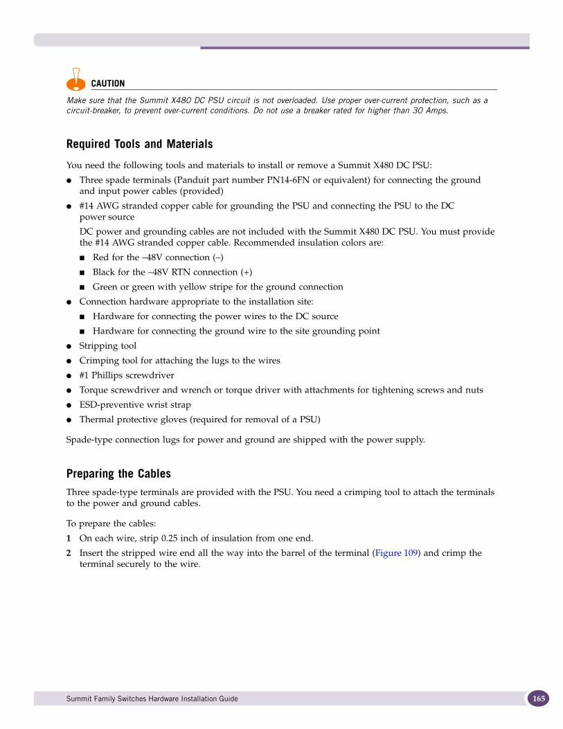
CAUTION
Make sure that the Summit X480 DC PSU circuit is not overloaded. Use proper over-current protection, such as a circuit-breaker, to prevent over-current conditions. Do not use a breaker rated for higher than 30 Amps.
Required Tools and Materials
You need the following tools and materials to install or remove a Summit X480 DC PSU:
● Three spade terminals (Panduit part number PN14-6FN or equivalent) for connecting the ground and input power cables (provided)
● #14 AWG stranded copper cable for grounding the PSU and connecting the PSU to the DC power source
DC power and grounding cables are not included with the Summit X480 DC PSU. You must provide the #14 AWG stranded copper cable. Recommended insulation colors are:
■ Red for the –48V connection (–)
■ Black for the –48V RTN connection (+)
■ Green or green with yellow stripe for the ground connection
● Connection hardware appropriate to the installation site:
■ Hardware for connecting the power wires to the DC source
■ Hardware for connecting the ground wire to the site grounding point
● Stripping tool
● Crimping tool for attaching the lugs to the wires
● #1 Phillips screwdriver
● Torque screwdriver and wrench or torque driver with attachments for tightening screws and nuts
● ESD-preventive wrist strap
● Thermal protective gloves (required for removal of a PSU)
Spade-type connection lugs for power and ground are shipped with the power supply.
Preparing the CablesThree spade-type terminals are provided with the PSU. You need a crimping tool to attach the terminals to the power and ground cables.
To prepare the cables:
1 On each wire, strip 0.25 inch of insulation from one end.
2 Insert the stripped wire end all the way into the barrel of the terminal (Figure 109) and crimp the terminal securely to the wire.
Summit Family Switches Hardware Installation Guide 165
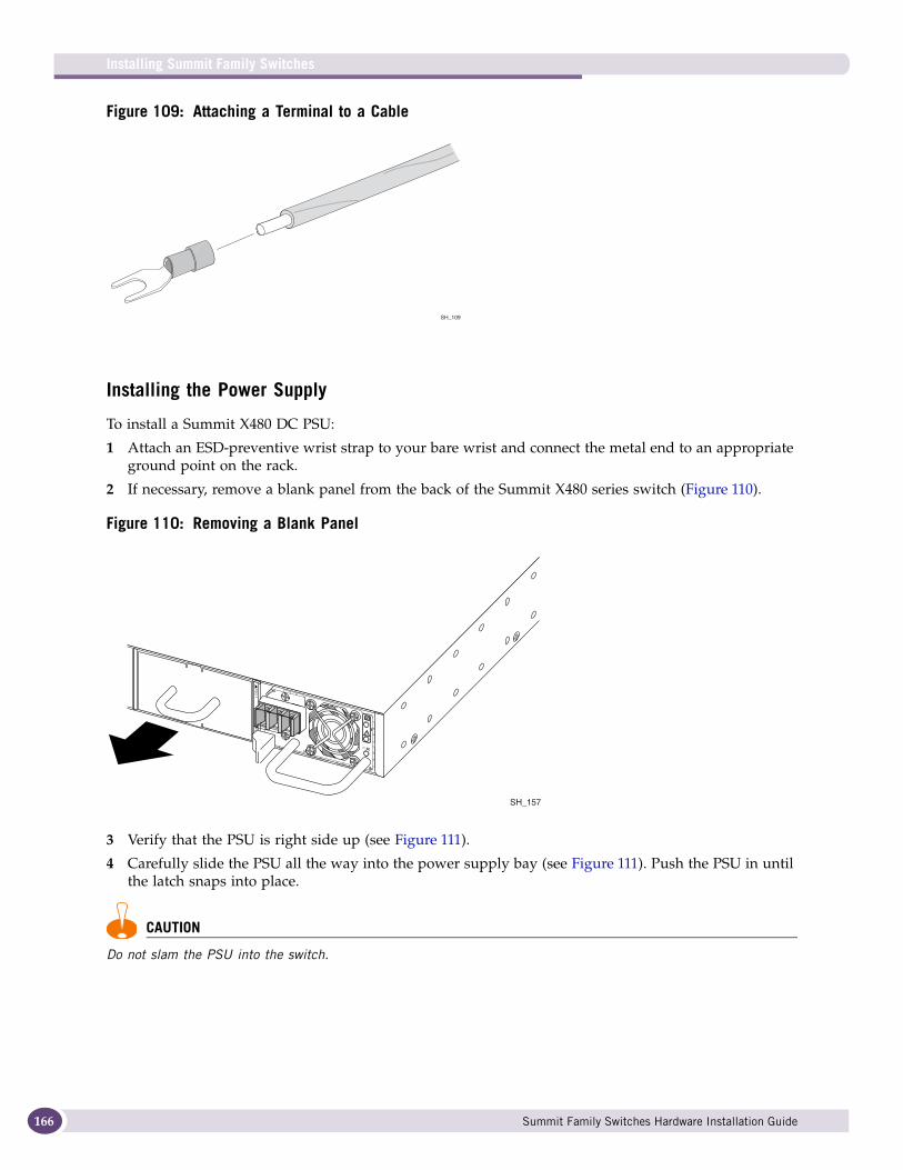
Installing Summit Family Switches
166
Figure 109: Attaching a Terminal to a Cable
Installing the Power Supply
To install a Summit X480 DC PSU:
1 Attach an ESD-preventive wrist strap to your bare wrist and connect the metal end to an appropriate ground point on the rack.
2 If necessary, remove a blank panel from the back of the Summit X480 series switch (Figure 110).
Figure 110: Removing a Blank Panel
3 Verify that the PSU is right side up (see Figure 111).
4 Carefully slide the PSU all the way into the power supply bay (see Figure 111). Push the PSU in until the latch snaps into place.
CAUTION
Do not slam the PSU into the switch.
SH_109
SH_157
Summit Family Switches Hardware Installation Guide
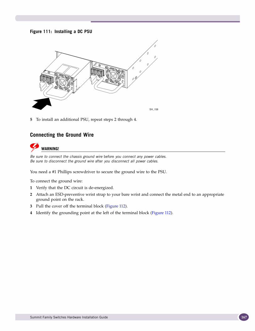
Figure 111: Installing a DC PSU
5 To install an additional PSU, repeat steps 2 through 4.
Connecting the Ground Wire
WARNING!
Be sure to connect the chassis ground wire before you connect any power cables. Be sure to disconnect the ground wire after you disconnect all power cables.
You need a #1 Phillips screwdriver to secure the ground wire to the PSU.
To connect the ground wire:
1 Verify that the DC circuit is de-energized.
2 Attach an ESD-preventive wrist strap to your bare wrist and connect the metal end to an appropriate ground point on the rack.
3 Pull the cover off the terminal block (Figure 112).
4 Identify the grounding point at the left of the terminal block (Figure 112).
SH_158
Summit Family Switches Hardware Installation Guide 167
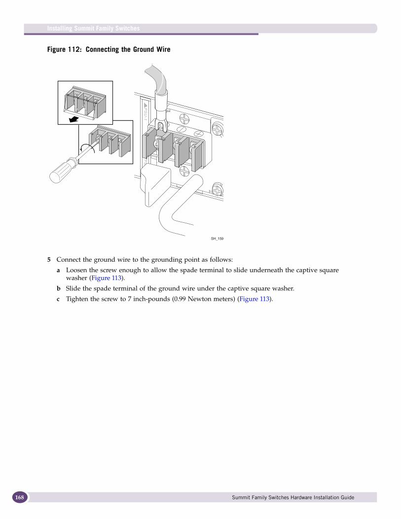
Installing Summit Family Switches
168
Figure 112: Connecting the Ground Wire
5 Connect the ground wire to the grounding point as follows:
a Loosen the screw enough to allow the spade terminal to slide underneath the captive square washer (Figure 113).
b Slide the spade terminal of the ground wire under the captive square washer.
c Tighten the screw to 7 inch-pounds (0.99 Newton meters) (Figure 113).
SH_159
Summit Family Switches Hardware Installation Guide
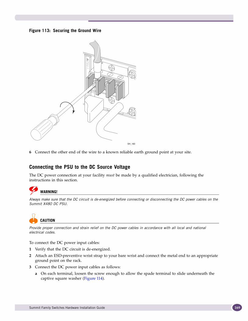
Figure 113: Securing the Ground Wire
6 Connect the other end of the wire to a known reliable earth ground point at your site.
Connecting the PSU to the DC Source VoltageThe DC power connection at your facility must be made by a qualified electrician, following the instructions in this section.
WARNING!
Always make sure that the DC circuit is de-energized before connecting or disconnecting the DC power cables on the Summit X480 DC PSU.
CAUTION
Provide proper connection and strain relief on the DC power cables in accordance with all local and national electrical codes.
To connect the DC power input cables:
1 Verify that the DC circuit is de-energized.
2 Attach an ESD-preventive wrist strap to your bare wrist and connect the metal end to an appropriate ground point on the rack.
3 Connect the DC power input cables as follows:
a On each terminal, loosen the screw enough to allow the spade terminal to slide underneath the captive square washer (Figure 114).
SH_160
Summit Family Switches Hardware Installation Guide 169
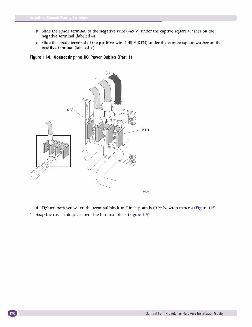
Installing Summit Family Switches
170
b Slide the spade terminal of the negative wire (–48 V) under the captive square washer on the negative terminal (labeled –).
c Slide the spade terminal of the positive wire (–48 V RTN) under the captive square washer on the positive terminal (labeled +).
Figure 114: Connecting the DC Power Cables (Part 1)
d Tighten both screws on the terminal block to 7 inch-pounds (0.99 Newton meters) (Figure 115).
4 Snap the cover into place over the terminal block (Figure 115).
SH_161
(+)
(–)
RTN
-48V
Summit Family Switches Hardware Installation Guide
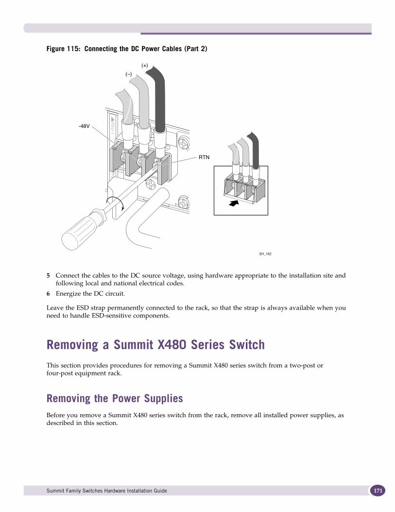
Figure 115: Connecting the DC Power Cables (Part 2)
5 Connect the cables to the DC source voltage, using hardware appropriate to the installation site and following local and national electrical codes.
6 Energize the DC circuit.
Leave the ESD strap permanently connected to the rack, so that the strap is always available when you need to handle ESD-sensitive components.
Removing a Summit X480 Series SwitchThis section provides procedures for removing a Summit X480 series switch from a two-post or four-post equipment rack.
Removing the Power SuppliesBefore you remove a Summit X480 series switch from the rack, remove all installed power supplies, as described in this section.
SH_162
(+)
(–)
RTN
-48V
Summit Family Switches Hardware Installation Guide 171

Installing Summit Family Switches
172
Removing a Summit X480 AC Power Supply
CAUTION
The PSU may be hot to the touch; wear thermal protective gloves when handling the PSU during removal.
To remove a Summit X480 AC PSU:
1 Attach an ESD-preventive wrist strap to your bare wrist and connect the metal end to an appropriate grounding point.
2 Disconnect the AC power cord from the wall outlet and from the power input connector on the PSU.
3 Push the latching tab to the right as you pull outward on the handle to disengage the PSU internal connectors (see Figure 116).
Figure 116: Removing an AC PSU
4 Carefully slide the PSU the rest of the way out of the switch.
5 If a replacement PSU will not be installed, install a cover over the unoccupied power supply bay.
NOTE
Unoccupied power supply bays must always be covered to maintain proper system ventilation and EMI levels.
Removing a Summit X480 DC Power Supply
WARNING!
Be sure to disconnect all power cables before you disconnect the chassis ground wire.
CAUTION
The DC PSU may be hot to the touch; use thermal protective gloves when handling the PSU during removal.
SH_139
Summit Family Switches Hardware Installation Guide
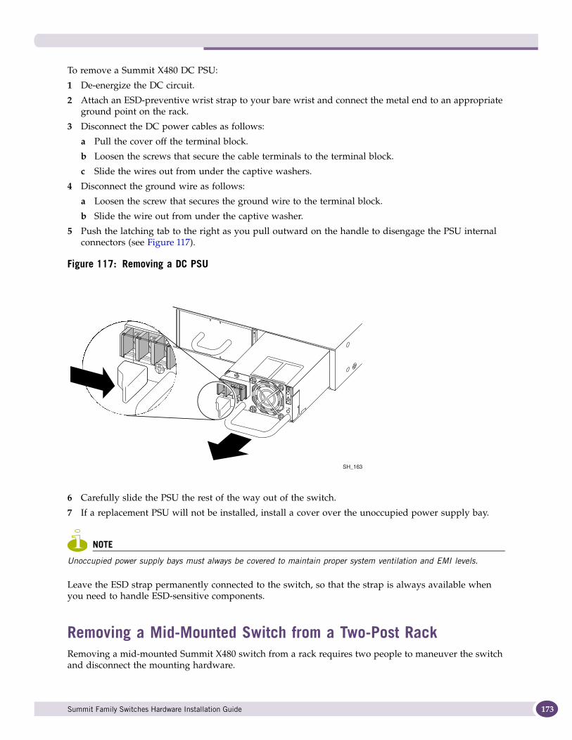
To remove a Summit X480 DC PSU:
1 De-energize the DC circuit.
2 Attach an ESD-preventive wrist strap to your bare wrist and connect the metal end to an appropriate ground point on the rack.
3 Disconnect the DC power cables as follows:
a Pull the cover off the terminal block.
b Loosen the screws that secure the cable terminals to the terminal block.
c Slide the wires out from under the captive washers.
4 Disconnect the ground wire as follows:
a Loosen the screw that secures the ground wire to the terminal block.
b Slide the wire out from under the captive washer.
5 Push the latching tab to the right as you pull outward on the handle to disengage the PSU internal connectors (see Figure 117).
Figure 117: Removing a DC PSU
6 Carefully slide the PSU the rest of the way out of the switch.
7 If a replacement PSU will not be installed, install a cover over the unoccupied power supply bay.
NOTE
Unoccupied power supply bays must always be covered to maintain proper system ventilation and EMI levels.
Leave the ESD strap permanently connected to the switch, so that the strap is always available when you need to handle ESD-sensitive components.
Removing a Mid-Mounted Switch from a Two-Post RackRemoving a mid-mounted Summit X480 switch from a rack requires two people to maneuver the switch and disconnect the mounting hardware.
SH_163
Summit Family Switches Hardware Installation Guide 173

Installing Summit Family Switches
174
To remove a mid-mounted Summit X480 series switch from a two-post rack:
1 Attach an ESD-preventive wrist strap to your wrist and connect the metal end to an appropriate ground point on the rack.
2 Verify that the power supplies have been removed from the switch.
3 At the front of the equipment rack, support the switch while you remove the rack-mounting screws holding the front mounting brackets in place against the rack post (Figure 118).
Figure 118: Removing the Front Mounting Screws from a Mid-Mount Installation
4 Remove the screws holding the front mounting brackets to the sides of the switch, and set the mounting brackets aside.
5 Support the front and back of the switch as you slide the switch back, off the rear mounting brackets, and out of the rack (Figure 119).
Set the switch on a secure work surface.
Figure 119: Removing a Mid-Mounted Switch from a Two-Post Rack
SH_130
SH_127
Summit Family Switches Hardware Installation Guide

6 Remove the rack-mounting screws and detach the rear mounting brackets from the rack post (Figure 120).
Figure 120: Removing the Rear Mounting Brackets
Removing a Front-Mounted Switch from a Two-Post RackRemoving a front-mounted Summit X480 switch from a rack requires two people to maneuver the switch and disconnect the mounting hardware.
To remove a front-mounted switch:
1 Attach an ESD-preventive wrist strap to your wrist and connect the metal end to an appropriate ground point on the rack.
2 Verify that all power supplies have been removed from the switch.
3 Support the switch while you remove the rack-mounting screws holding the front mounting brackets in place against the rack post (Figure 121).
4 Slide the switch out of the rack.
SH_125
Summit Family Switches Hardware Installation Guide 175
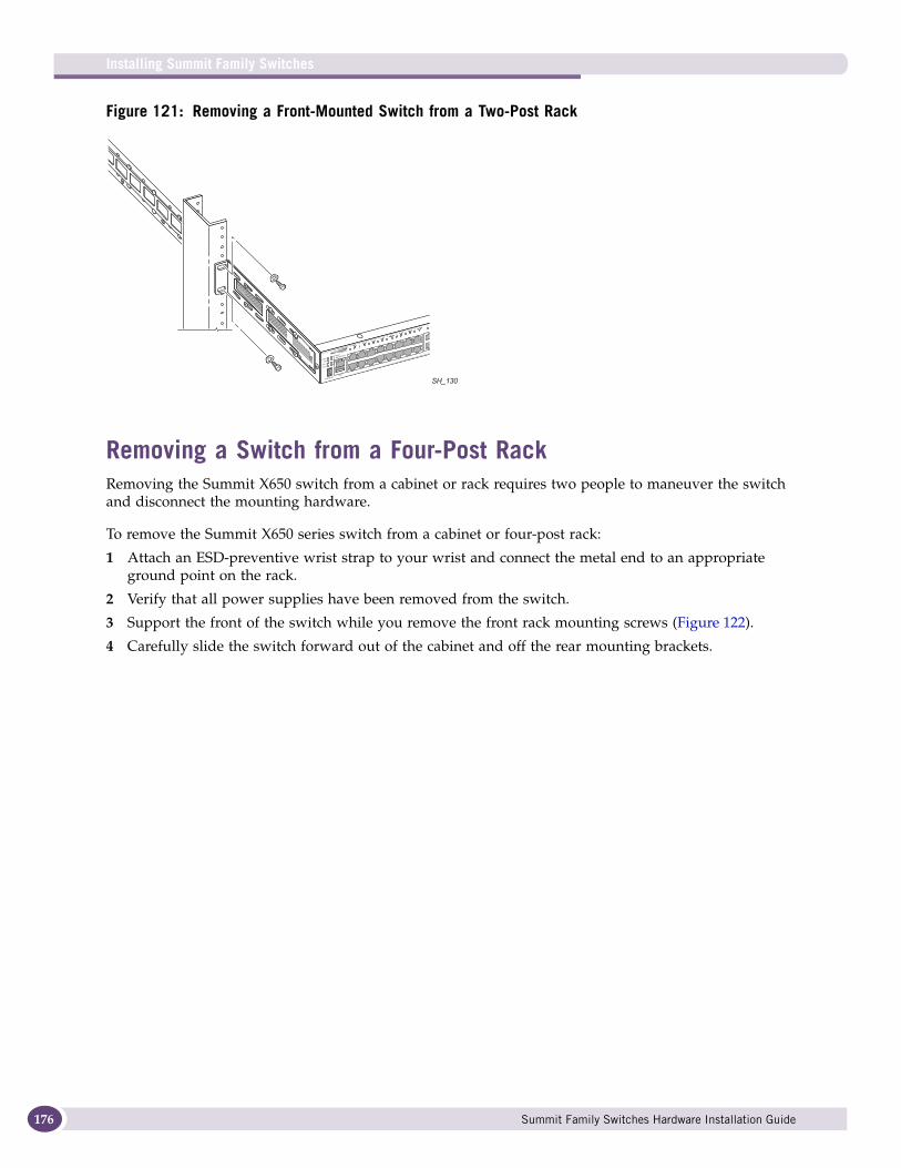
Installing Summit Family Switches
176
Figure 121: Removing a Front-Mounted Switch from a Two-Post Rack
Removing a Switch from a Four-Post RackRemoving the Summit X650 switch from a cabinet or rack requires two people to maneuver the switch and disconnect the mounting hardware.
To remove the Summit X650 series switch from a cabinet or four-post rack:
1 Attach an ESD-preventive wrist strap to your wrist and connect the metal end to an appropriate ground point on the rack.
2 Verify that all power supplies have been removed from the switch.
3 Support the front of the switch while you remove the front rack mounting screws (Figure 122).
4 Carefully slide the switch forward out of the cabinet and off the rear mounting brackets.
SH_130
Summit Family Switches Hardware Installation Guide
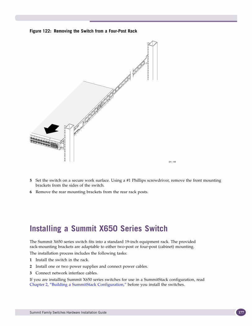
Figure 122: Removing the Switch from a Four-Post Rack
5 Set the switch on a secure work surface. Using a #1 Phillips screwdriver, remove the front mounting brackets from the sides of the switch.
6 Remove the rear mounting brackets from the rear rack posts.
Installing a Summit X650 Series SwitchThe Summit X650 series switch fits into a standard 19-inch equipment rack. The provided rack-mounting brackets are adaptable to either two-post or four-post (cabinet) mounting.
The installation process includes the following tasks:
1 Install the switch in the rack.
2 Install one or two power supplies and connect power cables.
3 Connect network interface cables.
If you are installing Summit X650 series switches for use in a SummitStack configuration, read Chapter 2, “Building a SummitStack Configuration,” before you install the switches.
SH_148
Summit Family Switches Hardware Installation Guide 177
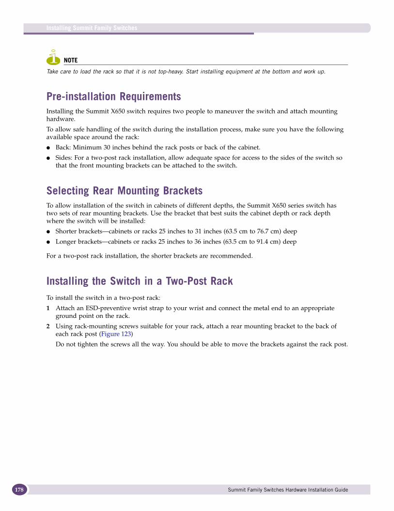
Installing Summit Family Switches
178
NOTE
Take care to load the rack so that it is not top-heavy. Start installing equipment at the bottom and work up.
Pre-installation RequirementsInstalling the Summit X650 switch requires two people to maneuver the switch and attach mounting hardware.
To allow safe handling of the switch during the installation process, make sure you have the following available space around the rack:
● Back: Minimum 30 inches behind the rack posts or back of the cabinet.
● Sides: For a two-post rack installation, allow adequate space for access to the sides of the switch so that the front mounting brackets can be attached to the switch.
Selecting Rear Mounting BracketsTo allow installation of the switch in cabinets of different depths, the Summit X650 series switch has two sets of rear mounting brackets. Use the bracket that best suits the cabinet depth or rack depth where the switch will be installed:
● Shorter brackets—cabinets or racks 25 inches to 31 inches (63.5 cm to 76.7 cm) deep
● Longer brackets—cabinets or racks 25 inches to 36 inches (63.5 cm to 91.4 cm) deep
For a two-post rack installation, the shorter brackets are recommended.
Installing the Switch in a Two-Post RackTo install the switch in a two-post rack:
1 Attach an ESD-preventive wrist strap to your wrist and connect the metal end to an appropriate ground point on the rack.
2 Using rack-mounting screws suitable for your rack, attach a rear mounting bracket to the back of each rack post (Figure 123)
Do not tighten the screws all the way. You should be able to move the brackets against the rack post.
Summit Family Switches Hardware Installation Guide
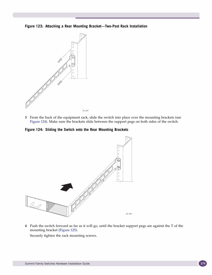
Figure 123: Attaching a Rear Mounting Bracket—Two-Post Rack Installation
3 From the back of the equipment rack, slide the switch into place over the mounting brackets (see Figure 124). Make sure the brackets slide between the support pegs on both sides of the switch.
Figure 124: Sliding the Switch onto the Rear Mounting Brackets
4 Push the switch forward as far as it will go, until the bracket support pegs are against the T of the mounting bracket (Figure 125).
Securely tighten the rack mounting screws.
SH_097
SH_082
Summit Family Switches Hardware Installation Guide 179
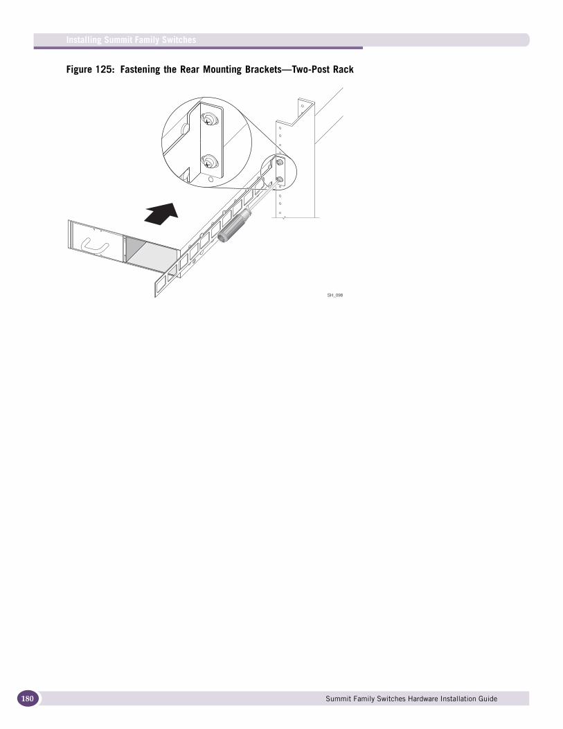
Installing Summit Family Switches
180
Figure 125: Fastening the Rear Mounting Brackets—Two-Post Rack
SH_098
Summit Family Switches Hardware Installation Guide

5 At the front of the switch, place a front mounting bracket against each side of the switch, in front of the ventilation openings in the side of the switch (Figure 126)
Make sure there is space between the bracket and the ventilation openings.
Figure 126: Positioning the Front Mounting Brackets—Two-Post Rack
6 Using the provided screws, attach each front bracket to the switch (Figure 126).
7 Slide the switch back in the rack until the front mounting brackets are against the front of the rack post (Figure 127).
Make sure that the ventilation holes in the side of the switch are within the open channel of the rack post.
Figure 127: Securing the Front Mounting Brackets to the Rack
8 Using mounting screws suitable for your equipment rack, secure the mounting brackets to the front of the rack post.
SH_099
SH_100
Summit Family Switches Hardware Installation Guide 181
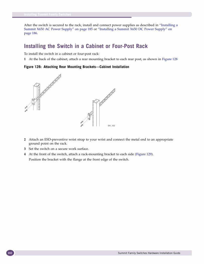
Installing Summit Family Switches
182
After the switch is secured to the rack, install and connect power supplies as described in “Installing a Summit X650 AC Power Supply” on page 185 or “Installing a Summit X650 DC Power Supply” on page 186.
Installing the Switch in a Cabinet or Four-Post RackTo install the switch in a cabinet or four-post rack:
1 At the back of the cabinet, attach a rear mounting bracket to each rear post, as shown in Figure 128
Figure 128: Attaching Rear Mounting Brackets—Cabinet Installation
2 Attach an ESD-preventive wrist strap to your wrist and connect the metal end to an appropriate ground point on the rack.
3 Set the switch on a secure work surface.
4 At the front of the switch, attach a rack-mounting bracket to each side (Figure 129).
Position the bracket with the flange at the front edge of the switch.
SH_102
Summit Family Switches Hardware Installation Guide
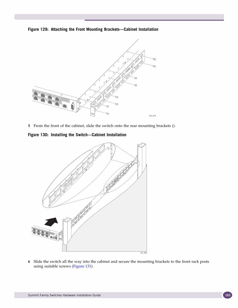
Figure 129: Attaching the Front Mounting Brackets—Cabinet Installation
5 From the front of the cabinet, slide the switch onto the rear mounting brackets ().
Figure 130: Installing the Switch—Cabinet Installation
6 Slide the switch all the way into the cabinet and secure the mounting brackets to the front rack posts using suitable screws (Figure 131).
SH_078
SH_080
Summit Family Switches Hardware Installation Guide 183
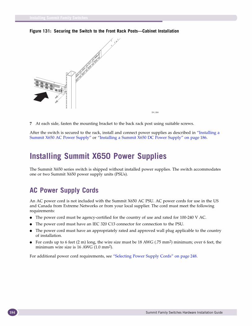
Installing Summit Family Switches
184
Figure 131: Securing the Switch to the Front Rack Posts—Cabinet Installation
7 At each side, fasten the mounting bracket to the back rack post using suitable screws.
After the switch is secured to the rack, install and connect power supplies as described in “Installing a Summit X650 AC Power Supply” or “Installing a Summit X650 DC Power Supply” on page 186.
Installing Summit X650 Power SuppliesThe Summit X650 series switch is shipped without installed power supplies. The switch accommodates one or two Summit X650 power supply units (PSUs).
AC Power Supply CordsAn AC power cord is not included with the Summit X650 AC PSU. AC power cords for use in the US and Canada from Extreme Networks or from your local supplier. The cord must meet the following requirements:
● The power cord must be agency-certified for the country of use and rated for 100-240 V AC.
● The power cord must have an IEC 320 C13 connector for connection to the PSU.
● The power cord must have an appropriately rated and approved wall plug applicable to the country of installation.
● For cords up to 6 feet (2 m) long, the wire size must be 18 AWG (.75 mm2) minimum; over 6 feet, the minimum wire size is 16 AWG (1.0 mm2).
For additional power cord requirements, see “Selecting Power Supply Cords” on page 248.
SH_084
Summit Family Switches Hardware Installation Guide
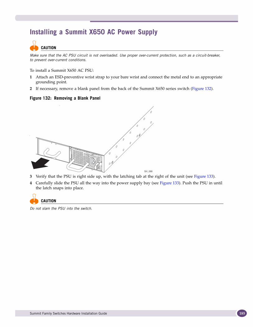
Installing a Summit X650 AC Power Supply
CAUTION
Make sure that the AC PSU circuit is not overloaded. Use proper over-current protection, such as a circuit-breaker, to prevent over-current conditions.
To install a Summit X650 AC PSU:
1 Attach an ESD-preventive wrist strap to your bare wrist and connect the metal end to an appropriate grounding point.
2 If necessary, remove a blank panel from the back of the Summit X650 series switch (Figure 132).
Figure 132: Removing a Blank Panel
3 Verify that the PSU is right side up, with the latching tab at the right of the unit (see Figure 133).
4 Carefully slide the PSU all the way into the power supply bay (see Figure 133). Push the PSU in until the latch snaps into place.
CAUTION
Do not slam the PSU into the switch.
SH_088
Summit Family Switches Hardware Installation Guide 185
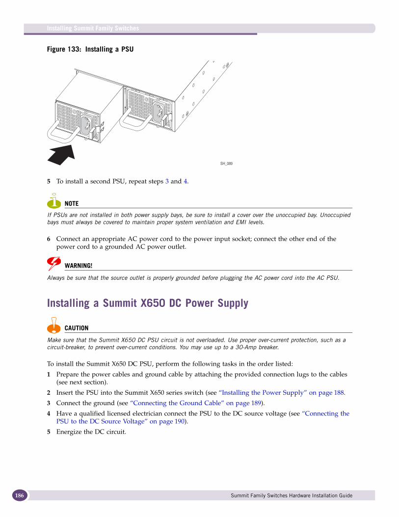
Installing Summit Family Switches
186
Figure 133: Installing a PSU
5 To install a second PSU, repeat steps 3 and 4.
NOTE
If PSUs are not installed in both power supply bays, be sure to install a cover over the unoccupied bay. Unoccupied bays must always be covered to maintain proper system ventilation and EMI levels.
6 Connect an appropriate AC power cord to the power input socket; connect the other end of the power cord to a grounded AC power outlet.
WARNING!
Always be sure that the source outlet is properly grounded before plugging the AC power cord into the AC PSU.
Installing a Summit X650 DC Power Supply
CAUTION
Make sure that the Summit X650 DC PSU circuit is not overloaded. Use proper over-current protection, such as a circuit-breaker, to prevent over-current conditions. You may use up to a 30-Amp breaker.
To install the Summit X650 DC PSU, perform the following tasks in the order listed:
1 Prepare the power cables and ground cable by attaching the provided connection lugs to the cables (see next section).
2 Insert the PSU into the Summit X650 series switch (see “Installing the Power Supply” on page 188.
3 Connect the ground (see “Connecting the Ground Cable” on page 189).
4 Have a qualified licensed electrician connect the PSU to the DC source voltage (see “Connecting the PSU to the DC Source Voltage” on page 190).
5 Energize the DC circuit.
SH_089
Summit Family Switches Hardware Installation Guide
Required Tools and Materials
You need the following tools and materials to install or remove a Summit X650 DC PSU:
● Two spade terminals (Tyco part number 130496 or equivalent) for connecting the input power cables (provided)
● One ring terminal (Tyco part number 130496 or equivalent) and screw with captive lock washer (type M3.5) for connecting the ground wire (both provided)
● #12 AWG stranded copper cable for grounding the PSU and connecting the PSU to the DC power source
A DC power cord is not included with the Summit X650 DC PSU. You must provide the #12 AWG stranded copper cable. Recommended insulation colors are:
■ Red for the –48V connection (–)
■ Black for the –48V RTN connection (+)
■ Green or green with yellow stripe for the ground connection
● Connection hardware appropriate to the installation site:
■ Hardware for connecting the power wires to the DC source
■ Hardware for connecting the ground wire to the site grounding point
● Stripping tool
● Crimping tool for attaching the lug to the ground wire
● #1 Phillips screwdriver
● Torque screwdriver and wrench or torque driver with attachments for tightening screws and nuts
● ESD-preventive wrist strap
● Thermal protective gloves (required for removal of a PSU)
Connection lugs for power and ground and a screw for connecting the ground wire are shipped with the power supply.
Preparing the CablesA ring terminal and two spade terminals are provided with the PSU. You need a crimping tool to attach the terminals to the power and ground cables.
To prepare the cables:
1 On each wire, strip 0.25 inch of insulation from one end.
2 Insert the stripped wire end all the way into the barrel of the terminal (Figure 134) and crimp the terminal securely to the wire.
Summit Family Switches Hardware Installation Guide 187

Installing Summit Family Switches
188
Figure 134: Attaching Terminals to Cables
Installing the Power Supply
CAUTION
The handle on the Summit X650 DC PSU is not designed to be used to lift or carry the Summit X650 series switch.
To install a Summit X650 DC PSU:
1 Attach an ESD-preventive wrist strap to your bare wrist and connect the metal end to an appropriate ground point on the rack.
2 If necessary, remove a blank panel from the back of the Summit X650 series switch (Figure 135).
Figure 135: Removing a Blank Panel
3 Verify that the PSU is right side up (see Figure 136).
4 Carefully slide the PSU all the way into the power supply bay (see Figure 136). Push the PSU in until the latch snaps into place.
CAUTION
Do not slam the PSU into the switch.
SH_109 SH_110Power connection wire Ground wire
SH_106
Summit Family Switches Hardware Installation Guide
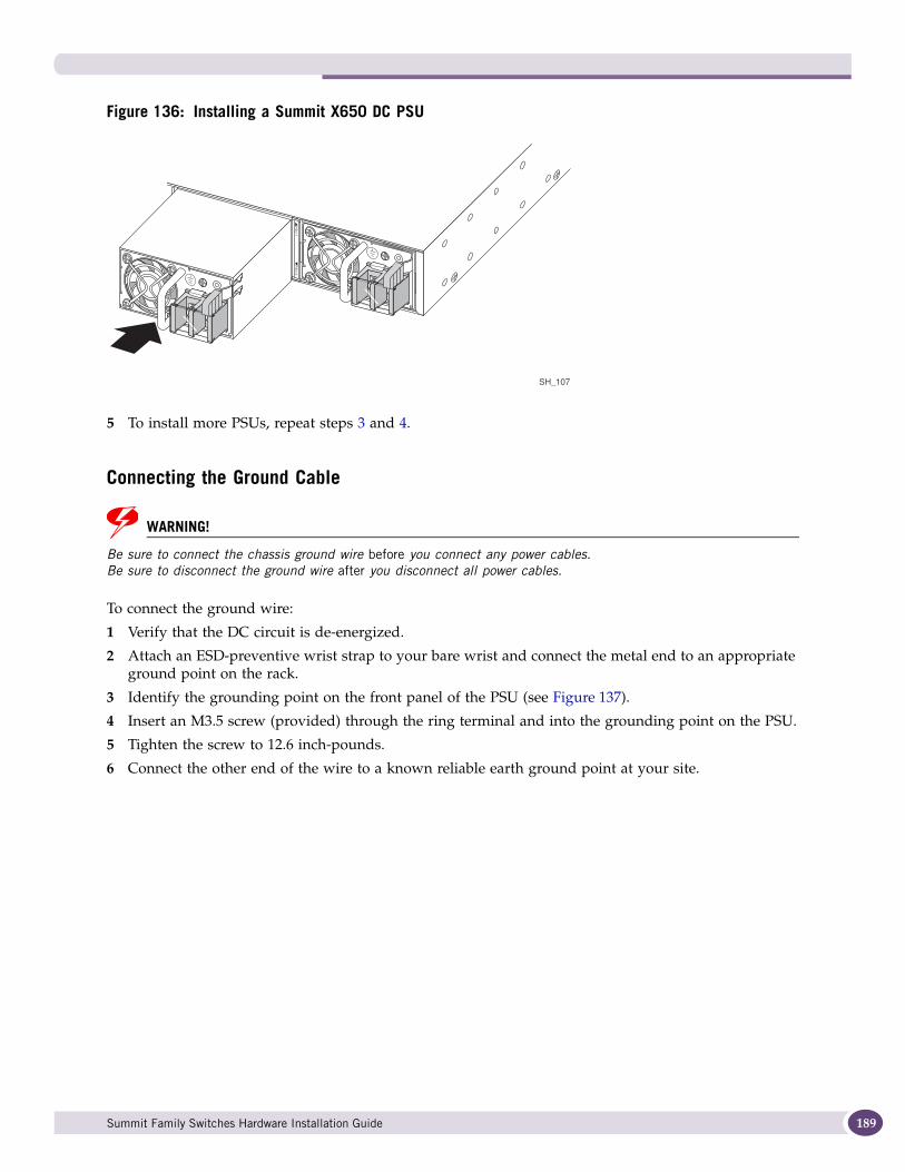
Figure 136: Installing a Summit X650 DC PSU
5 To install more PSUs, repeat steps 3 and 4.
Connecting the Ground Cable
WARNING!
Be sure to connect the chassis ground wire before you connect any power cables. Be sure to disconnect the ground wire after you disconnect all power cables.
To connect the ground wire:
1 Verify that the DC circuit is de-energized.
2 Attach an ESD-preventive wrist strap to your bare wrist and connect the metal end to an appropriate ground point on the rack.
3 Identify the grounding point on the front panel of the PSU (see Figure 137).
4 Insert an M3.5 screw (provided) through the ring terminal and into the grounding point on the PSU.
5 Tighten the screw to 12.6 inch-pounds.
6 Connect the other end of the wire to a known reliable earth ground point at your site.
SH_107
Summit Family Switches Hardware Installation Guide 189
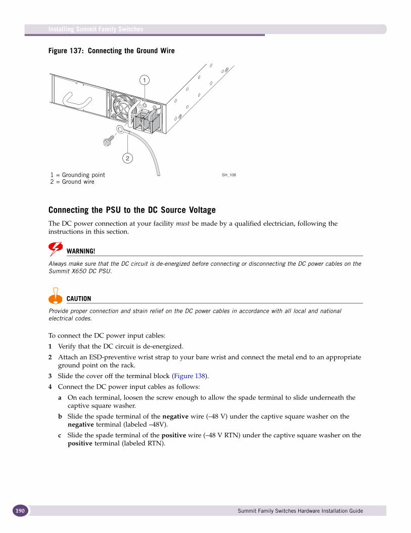
Installing Summit Family Switches
190
Figure 137: Connecting the Ground Wire
Connecting the PSU to the DC Source VoltageThe DC power connection at your facility must be made by a qualified electrician, following the instructions in this section.
WARNING!
Always make sure that the DC circuit is de-energized before connecting or disconnecting the DC power cables on the Summit X650 DC PSU.
CAUTION
Provide proper connection and strain relief on the DC power cables in accordance with all local and national electrical codes.
To connect the DC power input cables:
1 Verify that the DC circuit is de-energized.
2 Attach an ESD-preventive wrist strap to your bare wrist and connect the metal end to an appropriate ground point on the rack.
3 Slide the cover off the terminal block (Figure 138).
4 Connect the DC power input cables as follows:
a On each terminal, loosen the screw enough to allow the spade terminal to slide underneath the captive square washer.
b Slide the spade terminal of the negative wire (–48 V) under the captive square washer on the negative terminal (labeled –48V).
c Slide the spade terminal of the positive wire (–48 V RTN) under the captive square washer on the positive terminal (labeled RTN).
SH_108
1
2
1 = Grounding point2 = Ground wire
Summit Family Switches Hardware Installation Guide

Figure 138: Connecting the DC Power Cables (Part 1)
d Tighten both screws on the terminal block to 11 inch-pounds (Figure 139).
5 Slide the cover into place over the terminal block (Figure 139).
(+)
(–)
RTN-48V
SH_111
Summit Family Switches Hardware Installation Guide 191
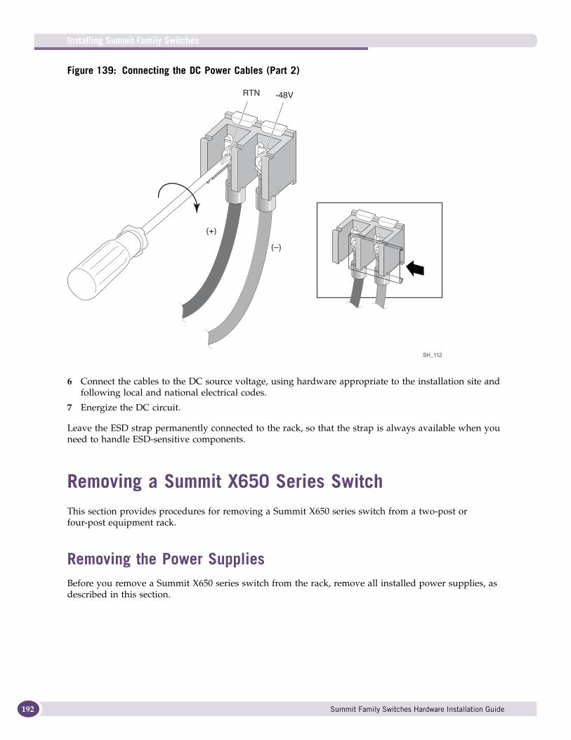
Installing Summit Family Switches
192
Figure 139: Connecting the DC Power Cables (Part 2)
6 Connect the cables to the DC source voltage, using hardware appropriate to the installation site and following local and national electrical codes.
7 Energize the DC circuit.
Leave the ESD strap permanently connected to the rack, so that the strap is always available when you need to handle ESD-sensitive components.
Removing a Summit X650 Series Switch This section provides procedures for removing a Summit X650 series switch from a two-post or four-post equipment rack.
Removing the Power SuppliesBefore you remove a Summit X650 series switch from the rack, remove all installed power supplies, as described in this section.
SH_112
(+)
(–)
RTN -48V
Summit Family Switches Hardware Installation Guide
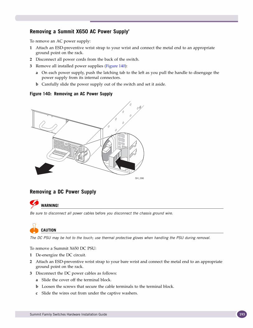
Removing a Summit X650 AC Power Supply’
To remove an AC power supply:
1 Attach an ESD-preventive wrist strap to your wrist and connect the metal end to an appropriate ground point on the rack.
2 Disconnect all power cords from the back of the switch.
3 Remove all installed power supplies (Figure 140):
a On each power supply, push the latching tab to the left as you pull the handle to disengage the power supply from its internal connectors.
b Carefully slide the power supply out of the switch and set it aside.
Figure 140: Removing an AC Power Supply
Removing a DC Power Supply
WARNING!
Be sure to disconnect all power cables before you disconnect the chassis ground wire.
CAUTION
The DC PSU may be hot to the touch; use thermal protective gloves when handling the PSU during removal.
To remove a Summit X650 DC PSU:
1 De-energize the DC circuit.
2 Attach an ESD-preventive wrist strap to your bare wrist and connect the metal end to an appropriate ground point on the rack.
3 Disconnect the DC power cables as follows:
a Slide the cover off the terminal block.
b Loosen the screws that secure the cable terminals to the terminal block.
c Slide the wires out from under the captive washers.
SH_096
Summit Family Switches Hardware Installation Guide 193
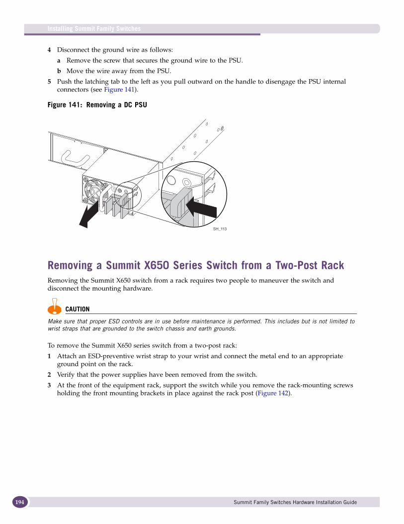
Installing Summit Family Switches
194
4 Disconnect the ground wire as follows:
a Remove the screw that secures the ground wire to the PSU.
b Move the wire away from the PSU.
5 Push the latching tab to the left as you pull outward on the handle to disengage the PSU internal connectors (see Figure 141).
Figure 141: Removing a DC PSU
Removing a Summit X650 Series Switch from a Two-Post RackRemoving the Summit X650 switch from a rack requires two people to maneuver the switch and disconnect the mounting hardware.
CAUTION
Make sure that proper ESD controls are in use before maintenance is performed. This includes but is not limited to wrist straps that are grounded to the switch chassis and earth grounds.
To remove the Summit X650 series switch from a two-post rack:
1 Attach an ESD-preventive wrist strap to your wrist and connect the metal end to an appropriate ground point on the rack.
2 Verify that the power supplies have been removed from the switch.
3 At the front of the equipment rack, support the switch while you remove the rack-mounting screws holding the front mounting brackets in place against the rack post (Figure 142).
SH_113
Summit Family Switches Hardware Installation Guide

Figure 142: Removing the Front Mounting Screws from a Two-Post Rack
4 Remove the screws holding the front mounting brackets to the sides of the switch, and set the mounting brackets aside.
5 Support the front and back of the switch as you slide the switch back, off the rear mounting brackets, and out of the rack (Figure 143).
Set the switch on a secure work surface.
Figure 143: Removing the Switch from a Two-Post Rack
SH_100
SH_101
Summit Family Switches Hardware Installation Guide 195
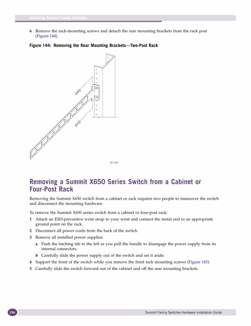
Installing Summit Family Switches
196
6 Remove the rack-mounting screws and detach the rear mounting brackets from the rack post (Figure 144).
Figure 144: Removing the Rear Mounting Brackets—Two-Post Rack
Removing a Summit X650 Series Switch from a Cabinet or Four-Post RackRemoving the Summit X650 switch from a cabinet or rack requires two people to maneuver the switch and disconnect the mounting hardware.
To remove the Summit X650 series switch from a cabinet or four-post rack:
1 Attach an ESD-preventive wrist strap to your wrist and connect the metal end to an appropriate ground point on the rack.
2 Disconnect all power cords from the back of the switch.
3 Remove all installed power supplies:
a Push the latching tab to the left as you pull the handle to disengage the power supply from its internal connectors.
b Carefully slide the power supply out of the switch and set it aside.
4 Support the front of the switch while you remove the front rack mounting screws (Figure 145).
5 Carefully slide the switch forward out of the cabinet and off the rear mounting brackets.
SH_097
Summit Family Switches Hardware Installation Guide
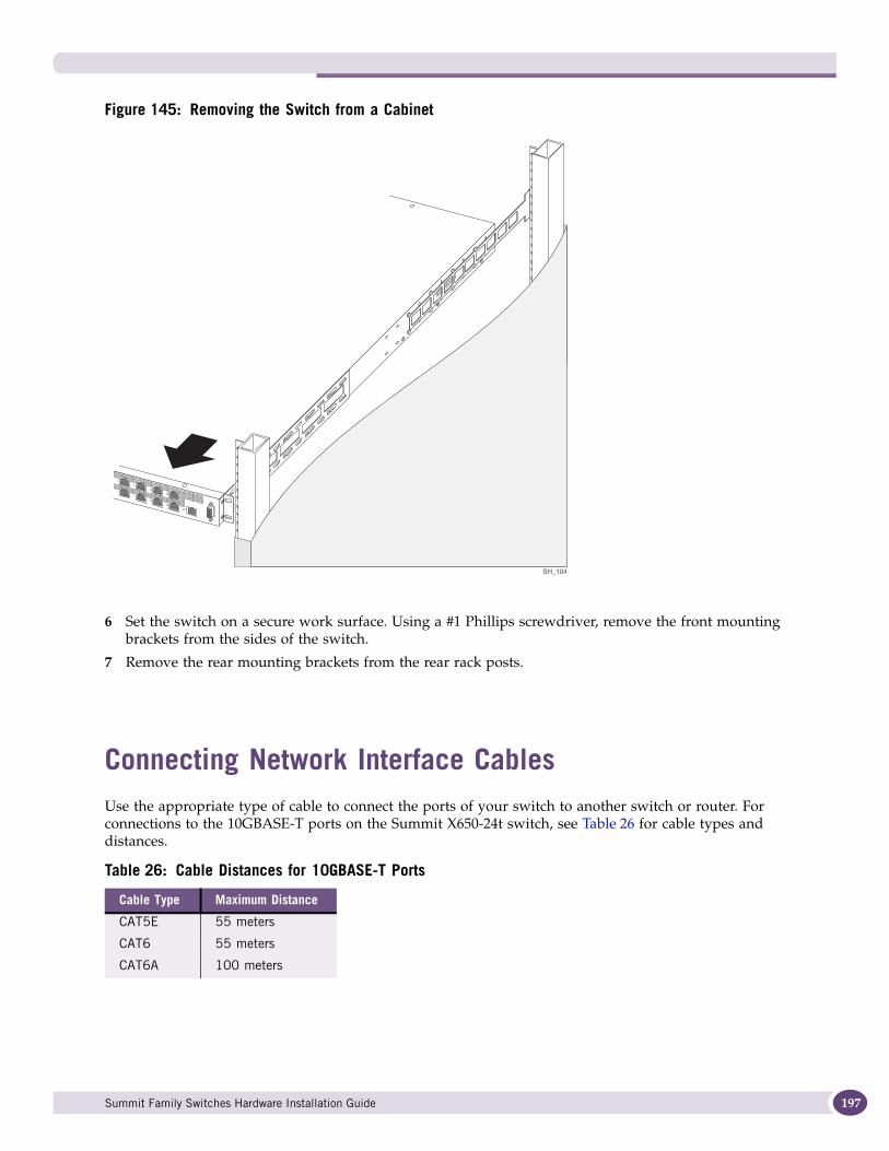
Figure 145: Removing the Switch from a Cabinet
6 Set the switch on a secure work surface. Using a #1 Phillips screwdriver, remove the front mounting brackets from the sides of the switch.
7 Remove the rear mounting brackets from the rear rack posts.
Connecting Network Interface CablesUse the appropriate type of cable to connect the ports of your switch to another switch or router. For connections to the 10GBASE-T ports on the Summit X650-24t switch, see Table 26 for cable types and distances.
Table 26: Cable Distances for 10GBASE-T Ports
Cable Type Maximum Distance
CAT5E 55 meters
CAT6 55 meters
CAT6A 100 meters
SH_104
Summit Family Switches Hardware Installation Guide 197

Installing Summit Family Switches
198
NOTE
Cables used for connection to the 10GBASE-T ports on the Summit X650-24t switch must meet the minimum requirements of the IEEE 802.3an standard.
Working carefully, one port at a time:
1 Verify that you have identified the correct cable for the port.
2 Use an alcohol wipe or other appropriate cleaning agent to clean the cable connectors; make sure they are free of dust, oil, and other contaminants.
3 If you are using optical fiber cable, align the transmit (Tx) and receive (Rx) connectors with the correct corresponding connectors on the switch or the I/O module.
4 Press the cable connectors into their mating connectors on the switch or I/O module until the cable connector is firmly seated.
5 Repeat steps 1 through 4 for the remaining cables on this or other switches or I/O modules.
6 Dress and secure the cable bundle to provide appropriate strain relief and protection against bends and kinks.
Initial Management AccessWhen you take your switch from the box and set it up for the first time, you must connect to the console to access the switch and perform initial security configuration. At this time you can also manually configure an IP address for the default VLAN.
Connecting Equipment to the Console PortConnection to the console port is used for direct local management. The console port settings are:
● Baud rate—9600
● Data bits—8
● Stop bit—1
● Parity—None
● Flow control—XON/XOFF
The terminal or PC with terminal-emulation software that you connect to an Extreme Networks switch must be configured with these settings. This procedure is described in the documentation supplied with the terminal.
Appropriate cables are available from your local supplier, or you can make your own. To ensure the electromagnetic compatibility of the unit, use only shielded serial cables. For connector pinouts associated with the console port, see “Console Connector Pinouts” on page 296.
Summit Family Switches Hardware Installation Guide
Logging In for the First TimeAfter your switch has completed all power on self-tests, it is operational. You can log in and configure an IP address for the default VLAN (named default).
NOTE
The management port is part of the management VLAN by default.
To manually configure the IP settings:
1 Connect a terminal or PC with terminal-emulation software to the console port on the Summit switch.
2 At the terminal, press [Return] one or more times until you see the login prompt.
3 At the login prompt, enter the default user name admin to log on with administrator privileges. For example:
login: admin
Administrator capabilities allow you to access all switch functions.
4 The system will ask a series of questions about the default management settings, which allow all forms of management access for convenience in setting the initial configuration. Answer each question based on the level of security needed for the particular management access type.
NOTE
For more information about logging in to the switch and configuring switch management access, see the ExtremeXOS Concepts Guide.
5 At the password prompt, press [Return].
The default user name admin has no password assigned to it. When you have successfully logged on to the system, the command line prompt displays the system name (for example, SummitX450>) in its prompt.
NOTE
For more information about how to assign a specific system name, see the ExtremeXOS Concepts Guide.
6 Assign an IP address and subnetwork mask for VLAN default by typing:
configure vlan default ipaddress 123.45.67.8 255.255.255.0
Your changes take effect immediately.
7 Save your configuration changes so that they will be in effect after the next system reboot by typing:
save
The configuration is saved to the configuration database of the MSM modules in the switch.
NOTE
For more information about saving configuration changes, see the ExtremeXOS Concepts Guide.
8 When you are finished with these tasks, log out of the switch by typing:
logout
Summit Family Switches Hardware Installation Guide 199

Installing Summit Family Switches
200
Summit Family Switches Hardware Installation Guide
6 Installing Summit External Power Supplies
This chapter describes how to install external power supplies with the Summit family switches. The chapter includes the following sections:
● Safety on page 201
● Installing an EPS-160 External Power Module (with EPS-T) on page 202
● Installing an EPS-LD External Power Supply on page 205
● Installing an EPS-500 External Power Supply Unit on page 208
● Installing an EPS-150DC External Power Module (with EPS-T2) on page 211
● Installing an EPS-600LS External Power Module on page 216
Read the information in this chapter thoroughly before you start to install or remove an external power supply.
SafetyOnly trained service personnel should perform service to Extreme Networks switches and their components. Trained service personnel have read all related installation manuals, have the technical training and experience necessary to be aware of the hazards to which they are exposed in performing a task, and are aware of measures to minimize the danger to themselves or other persons.
NOTE
See Appendix A, “Safety Information” for additional safety information and Appendix B, “Technical Specifications” for additional information regarding regulatory compliance certifications.
CAUTION
Be sure that proper ESD controls are in use before switch maintenance is performed. This includes but is not limited to wrist straps that are grounded to the switch chassis and earth grounds.
CAUTION
The EPS must be installed or removed only by trained service personnel in accordance with the installation instructions. Before installing or removing any components of the system, or before carrying out any maintenance procedures, read the safety information provided in Appendix A of this guide. Not following these precautions can result in equipment damage or shock.
WARNING!
Extreme Networks AC PSUs do not have switches for turning the unit on and off. Remove the wall plug from the electrical outlet to disconnect the power to an Extreme Networks AC PSU. Make sure that this connection is easily accessible.
Summit Family Switches Hardware Installation Guide 201
Installing Summit External Power Supplies
202
When the PSU is outside the chassis (not installed), do not plug the PSU into an electrical outlet. Plugging an uninstalled AC PSU into an electrical outlet exposes you to a hazardous energy and is a potential fire hazard.
WARNING!
Always be sure that the DC circuit is de-energized before connecting or disconnecting the DC wiring harness at the DC power socket on the rear of the EPS-150DC unit, and before connecting or disconnecting the redundant power cord between the switch and the EPS-150DC unit.
Pre-installation RequirementsYou need the following tools and equipment to install an external power supply:
● Electrostatic discharge (ESD)-preventive wrist strap
● # 1 Phillips screwdriver
● Rack mount screws suitable for your organization’s equipment rack
● Screwdriver suitable for use with your rack-mount screws
● AC power cord
An AC power cord is not included with the external power supply. You must obtain a power supply cord that meets the requirements listed under “Selecting Power Supply Cords” on page 248.
NOTE
When you connect an external power supply, consider all of the equipment that is connected to the power supply circuit to ensure that the circuit is not overloaded. Use proper overcurrent protection, such as a circuit breaker, to prevent overcurrent conditions.
The switch and each redundant power supply source should be plugged into separate branch circuits to provide redundancy.
Installing an EPS-160 External Power Module (with EPS-T)You can order the EPS-T chassis with one or two EPS-160 power supplies already installed. You can also order an additional power supply from your Extreme Networks reseller.
The EPS-T can be mounted in a rack or placed free-standing on a tabletop.
Rack-Mounting the EPS-T
CAUTION
Do not use the rack-mount brackets to suspend the EPS-T from under a table or desk, or to attach the EPS-T to a wall.
Summit Family Switches Hardware Installation Guide
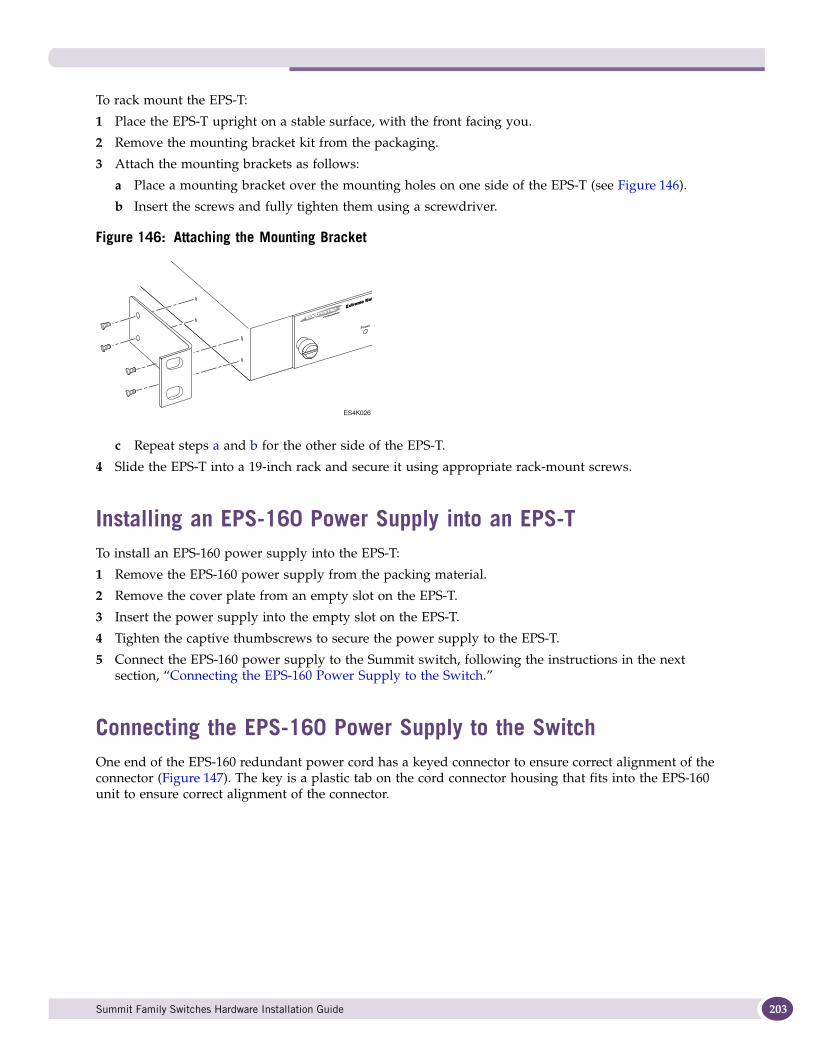
To rack mount the EPS-T:
1 Place the EPS-T upright on a stable surface, with the front facing you.
2 Remove the mounting bracket kit from the packaging.
3 Attach the mounting brackets as follows:
a Place a mounting bracket over the mounting holes on one side of the EPS-T (see Figure 146).
b Insert the screws and fully tighten them using a screwdriver.
Figure 146: Attaching the Mounting Bracket
c Repeat steps a and b for the other side of the EPS-T.
4 Slide the EPS-T into a 19-inch rack and secure it using appropriate rack-mount screws.
Installing an EPS-160 Power Supply into an EPS-TTo install an EPS-160 power supply into the EPS-T:
1 Remove the EPS-160 power supply from the packing material.
2 Remove the cover plate from an empty slot on the EPS-T.
3 Insert the power supply into the empty slot on the EPS-T.
4 Tighten the captive thumbscrews to secure the power supply to the EPS-T.
5 Connect the EPS-160 power supply to the Summit switch, following the instructions in the next section, “Connecting the EPS-160 Power Supply to the Switch.”
Connecting the EPS-160 Power Supply to the SwitchOne end of the EPS-160 redundant power cord has a keyed connector to ensure correct alignment of the connector (Figure 147). The key is a plastic tab on the cord connector housing that fits into the EPS-160 unit to ensure correct alignment of the connector.
ES4K026
Summit Family Switches Hardware Installation Guide 203
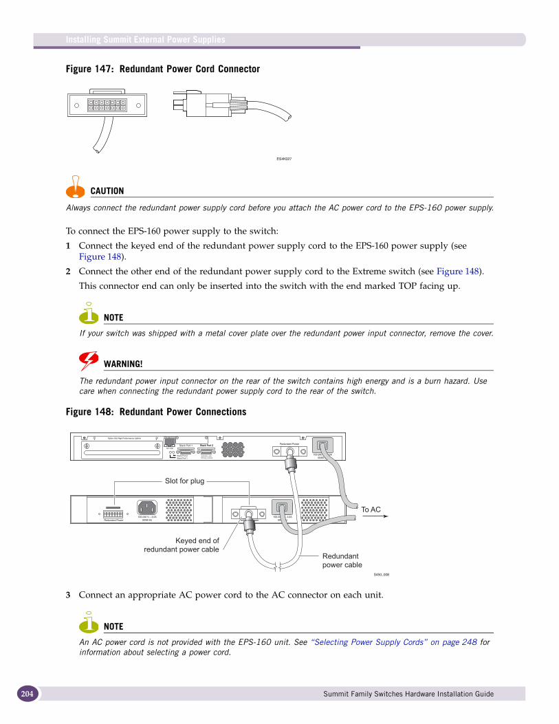
Installing Summit External Power Supplies
204
Figure 147: Redundant Power Cord Connector
CAUTION
Always connect the redundant power supply cord before you attach the AC power cord to the EPS-160 power supply.
To connect the EPS-160 power supply to the switch:
1 Connect the keyed end of the redundant power supply cord to the EPS-160 power supply (see Figure 148).
2 Connect the other end of the redundant power supply cord to the Extreme switch (see Figure 148).
This connector end can only be inserted into the switch with the end marked TOP facing up.
NOTE
If your switch was shipped with a metal cover plate over the redundant power input connector, remove the cover.
WARNING!
The redundant power input connector on the rear of the switch contains high energy and is a burn hazard. Use care when connecting the redundant power supply cord to the rear of the switch.
Figure 148: Redundant Power Connections
3 Connect an appropriate AC power cord to the AC connector on each unit.
NOTE
An AC power cord is not provided with the EPS-160 unit. See “Selecting Power Supply Cords” on page 248 for information about selecting a power cord.
ES4K027
S450_008
To AC
Slot for plug
Redundant
power cable
Keyed end of
redundant power cable
Summit Family Switches Hardware Installation Guide
The PSU-E LED on the front of the EPS-160 should light solid green to indicate that it is ready.
Table 27 shows the LED meanings for the EPS-160.
Removing an EPS-160 Power Supply from an EPS-TTo remove an EPS-160 power supply from an EPS-T:
1 Disconnect the AC power by removing the plug from the wall.
2 Disconnect the AC power cord from the EPS-160.
3 Disconnect the redundant power cord from the EPS-160.
4 Loosen the captive retaining screws on the front of the EPS-160 and slide it out of the EPS-T.
Installing an EPS-LD External Power SupplyThe EPS-LD power supply can be mounted in a rack or placed free-standing on a tabletop. You can position the EPS-LD facing either the front or the back of the rack. For this reason, each unit has two sets of mounting holes on each side. Extreme Networks recommends that you position the EPS-LD so that the power output connectors on the EPS-LD unit are on the same side as the external connector on the connecting switch.
CAUTION
Do not use the rack-mount brackets to suspend the EPS-LD from under a table or desk, or to attach the unit to a wall.
NOTE
An AC power cord is not provided with the EPS-LD power supply. See “Selecting Power Supply Cords” on page 248 for information about selecting a power cord.
Rack-mounting the EPS-LD Power Supply
NOTE
When installing an EPS-LD in a rack, make sure air vents are not restricted. Allow for elevated ambient operating temperatures when the EPS-LD is installed adjacent to other equipment. Be sure you mount the equipment in the rack so that the load is evenly distributed.
Table 27: LED Meanings on the EPS-160 Power Supply
Power LED Indicates
Green, solid The external power supply is operating normally.
Off The external power supply is not connected.
Summit Family Switches Hardware Installation Guide 205

Installing Summit External Power Supplies
206
To rack-mount each EPS-LD unit:
1 Place the EPS-LD unit upright on a stable surface, with the side you want to face to the front of the switch toward you.
2 Remove the mounting bracket kit from the packaging.
3 Attach the mounting brackets as follows:
a Place a mounting bracket over the mounting holes on one side of the unit (see Figure 149).
b Insert the provided screws and fully tighten them using a screwdriver.
Figure 149: Attaching the Mounting Bracket
c Repeat steps a and b for the other side of the EPS-LD unit.
4 Slide the EPS-LD into a 19-inch rack and secure it using appropriate rack-mount screws.
NOTE
Extreme Networks recommends that you position the EPS-LD so that the output connectors are on the same side as the external connector on the connecting switch. If you mount the EPS-LD with the connectors facing in the opposite direction from the Summit switch connector, leave at least 1 U between the switch and the EPS-LD through which to slide the power cords. Do not route the power cords around the equipment rack.
Connecting the EPS-LD to the Switch
CAUTION
Do not attach the AC power cord to the EPS-LD unit until the unit is properly grounded at the electrical outlet and the redundant power supply cord is connected.
One end of the EPS-LD cord has a keyed connector to ensure correct alignment of the connector (Figure 150). The key is a plastic tab on the cord connector housing that fits into the EPS-LD unit to ensure correct alignment of the connector.
Collin'sES4K026
XM_054
Summit Family Switches Hardware Installation Guide

Figure 150: EPS-LD Connector with Key
To connect the EPS-LD to the switch:
1 Connect the keyed end of the cord to the power supply unit (see Figure 151).
2 Align and tighten the captive retaining screws on the connector.
3 Connect the other end of the EPS-LD cord to the Extreme switch.
The connector fits in only one direction.
NOTE
If your switch was shipped with a metal cover plate over the redundant power input connector, remove the cover.
WARNING!
The redundant power input connector on the rear of the switch contains high energy and is a burn hazard. Use care when connecting the redundant power supply cord to the rear of the switch.
Figure 151: Connecting an EPS-LD Unit to a Switch
Connecting the EPS-LD to PowerAn AC input power cord is not provided with the EPS-LD. For information about power cord requirements, see “Selecting Power Supply Cords” on page 248.
Make sure the EPS-LD is connected to the switch before you connect the AC power.
Collin'sES4K027
XM_055
Collin'sES4K021A
XM_053
Slot for keyKeyed end of
redundant power cable
To AC
To AC
Extreme switch
EPS-LD
Redundantpower cable
Summit Family Switches Hardware Installation Guide 207
Installing Summit External Power Supplies
208
CAUTION
The EPS-LD does not have a switch for turning the unit on and off. You disconnect power to the EPS-LD by removing the plug from the electrical outlet. Make sure that this connection is easily accessible.
To connect the EPS-LD to power:
1 Connect the AC input power cord to the AC connector on the EPS-LD.
2 Connect the other end of the AC cord to the electrical outlet.
Make sure the electrical outlet is properly grounded.
The Power LED on the front of the EPS-LD turns solid green to indicate that it is ready.
Table 28 shows the LED meanings for the EPS-LD power supply.
Removing an EPS-LDTo remove an EPS-LD power supply:
1 Disconnect the AC power by removing the plug from the wall.
2 Disconnect the AC power cord from the EPS-LD unit.
3 Disconnect the cord between the Extreme switch and the EPS-LD.
4 Remove the screws from the EPS-LD mounting brackets.
5 Slide the EPS-LD out of the rack.
Installing an EPS-500 External Power Supply UnitYou can position the EPS-500 facing either the front or the back of the rack. For this reason, each unit has two sets of mounting holes on each side. Extreme Networks recommends that you position the EPS-500 unit so that the power output connectors of the EPS-500 unit are on the same side as the external connector on the connecting switch.
The EPS-500 unit can be mounted in a rack or placed free-standing on a tabletop.
NOTE
An AC power cord is not provided with the EPS-500 unit. See “Selecting Power Supply Cords” on page 248 for information about selecting a power cord.
Table 28: LED Meanings on the EPS-LD
Power LED Indicates
Green, solid The external power supply is operating normally.
Off The external power supply is not connected.
Summit Family Switches Hardware Installation Guide
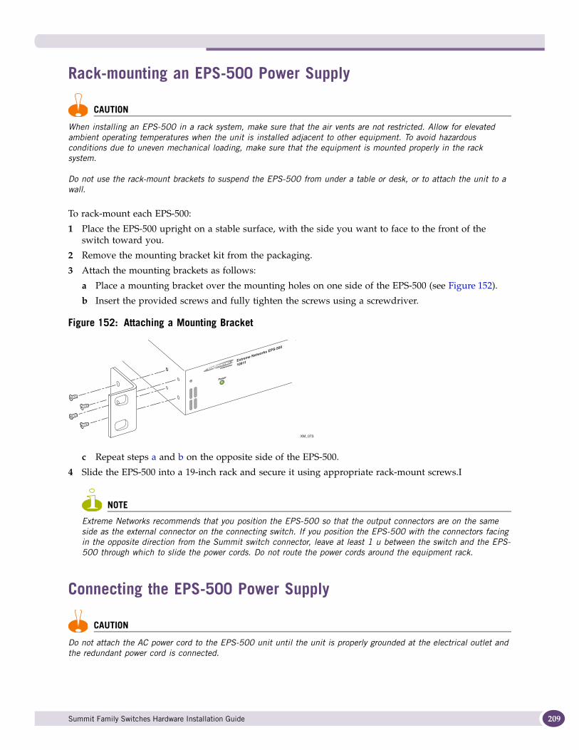
Rack-mounting an EPS-500 Power Supply
CAUTION
When installing an EPS-500 in a rack system, make sure that the air vents are not restricted. Allow for elevated ambient operating temperatures when the unit is installed adjacent to other equipment. To avoid hazardous conditions due to uneven mechanical loading, make sure that the equipment is mounted properly in the rack system.
Do not use the rack-mount brackets to suspend the EPS-500 from under a table or desk, or to attach the unit to a wall.
To rack-mount each EPS-500:
1 Place the EPS-500 upright on a stable surface, with the side you want to face to the front of the switch toward you.
2 Remove the mounting bracket kit from the packaging.
3 Attach the mounting brackets as follows:
a Place a mounting bracket over the mounting holes on one side of the EPS-500 (see Figure 152).
b Insert the provided screws and fully tighten the screws using a screwdriver.
Figure 152: Attaching a Mounting Bracket
c Repeat steps a and b on the opposite side of the EPS-500.
4 Slide the EPS-500 into a 19-inch rack and secure it using appropriate rack-mount screws.I
NOTE
Extreme Networks recommends that you position the EPS-500 so that the output connectors are on the same side as the external connector on the connecting switch. If you position the EPS-500 with the connectors facing in the opposite direction from the Summit switch connector, leave at least 1 u between the switch and the EPS-500 through which to slide the power cords. Do not route the power cords around the equipment rack.
Connecting the EPS-500 Power Supply
CAUTION
Do not attach the AC power cord to the EPS-500 unit until the unit is properly grounded at the electrical outlet and the redundant power cord is connected.
Collin'sES4K026
XM_073
Summit Family Switches Hardware Installation Guide 209
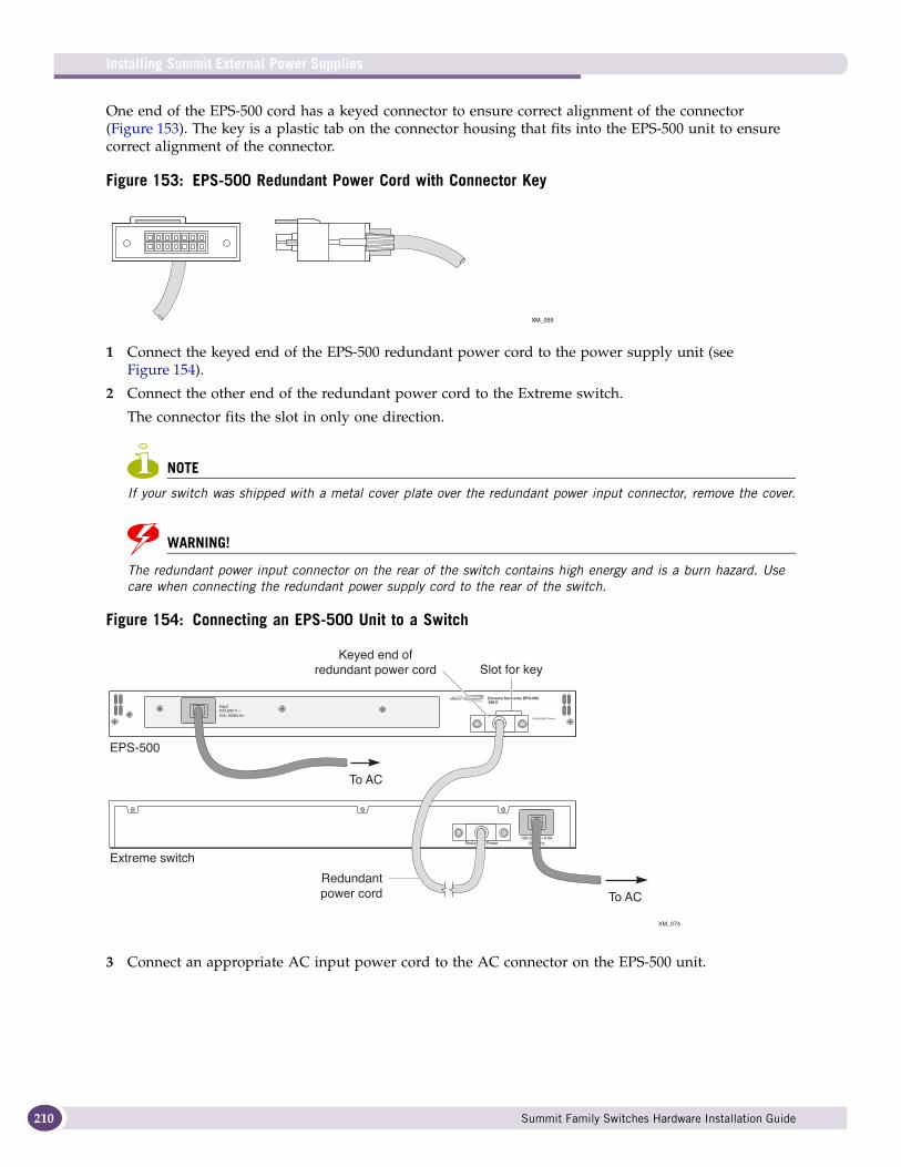
Installing Summit External Power Supplies
210
One end of the EPS-500 cord has a keyed connector to ensure correct alignment of the connector (Figure 153). The key is a plastic tab on the connector housing that fits into the EPS-500 unit to ensure correct alignment of the connector.
Figure 153: EPS-500 Redundant Power Cord with Connector Key
1 Connect the keyed end of the EPS-500 redundant power cord to the power supply unit (see Figure 154).
2 Connect the other end of the redundant power cord to the Extreme switch.
The connector fits the slot in only one direction.
NOTE
If your switch was shipped with a metal cover plate over the redundant power input connector, remove the cover.
WARNING!
The redundant power input connector on the rear of the switch contains high energy and is a burn hazard. Use care when connecting the redundant power supply cord to the rear of the switch.
Figure 154: Connecting an EPS-500 Unit to a Switch
3 Connect an appropriate AC input power cord to the AC connector on the EPS-500 unit.
Collin'sES4K027
XM_055
Collin'sES4K021A
XM_074
Slot for keyKeyed end of
redundant power cord
To AC
To AC
Extreme switch
EPS-500
Redundantpower cord
Summit Family Switches Hardware Installation Guide
NOTE
An AC power cord is not provided with the EPS-500 unit. See “Selecting Power Supply Cords” on page 248 for information about selecting a power cord.
CAUTION
The EPS-500 unit does not have a switch for turning the unit on and off. Disconnect power to the EPS-500 unit by removing the plug from the electrical outlet. Be sure that this connection is easily accessible to you.
4 Connect the other end of the AC power cord to the electrical outlet.
Be sure that the electrical outlet is properly grounded.
The Power LED on the front of the EPS-500 unit turns solid green to indicate that it is ready. Table 29 shows the LED meanings for the power supply.
Removing an EPS-500 Power SupplyTo remove an EPS-500 power supply:
1 Disconnect the AC power by removing the plug from the wall.
2 Disconnect the AC power cord from the EPS-500 power supply.
3 Remove the redundant power cord that connects the switch to the power supply.
4 Remove the mounting screws securing the power supply to the rack.
5 Slide the power supply out of the rack.
Installing an EPS-150DC External Power Module (with EPS-T2)The EPS-150DC power supply is a modular power supply for use in the EPS-T2 External Power System Tray. The EPS-T2 is a rack-mountable chassis or tray that holds one or two EPS-150DC power supplies. Each EPS-150DC provides one-to-one redundancy to an attached Extreme Networks switch. You must install the EPS-150DC power supply in the EPS-T2 tray.
NOTE
For centralized DC power connection, this product is intended to be installed in restricted access locations (dedicated equipment rooms, equipment closets, or the like) in accordance with Articles 110-16, 110-17, and 110-18 of the National Electric Code, ANSI/NFPA 70.
Table 29: LED Meanings on the EPS-500 Power Supply
Power LED Indicates
Green, solid The external power supply is operating normally.
Off The external power supply is not connected.
Summit Family Switches Hardware Installation Guide 211

Installing Summit External Power Supplies
212
CAUTION
Do not use the rack-mount brackets to suspend the EPS-T2 from under a table top or desk, or to attach the EPS-T2 to a wall.
Rack-mounting the EPS-T2To install the EPS-T2:
1 Place the EPS-T2 upright on a secure surface, with the front facing you.
2 Remove the mounting bracket kit from the packaging.
3 Attach the mounting brackets as follows:
a Place a mounting bracket over the mounting holes on one side of the EPS-T2 (see Figure 155).
b Insert the provided screws and fully tighten with a screwdriver.
Figure 155: Attaching the Mounting Bracket
c Repeat steps a and b for the other side of the EPS-T2.
4 Slide the EPS-T2 into a 19-inch rack and secure it using appropriate rack-mount screws.
Installing an EPS-150DC Power Supply
NOTE
Install the EPS-T2 before you begin installing the EPS-150DC.
WARNING!
Always be sure that the DC circuit is de-energized before connecting or disconnecting the DC wiring harness at the DC power socket on the rear of the EPS-150DC unit, and before connecting or disconnecting the redundant power cord between the switch and the EPS-150DC unit.
Installing an EPS-150DC unit consists of the following tasks:
● Connecting the DC wiring harness to the DC source voltage (see page 213).
This task must be performed by a licensed, qualified electrician.
ES4K026
Summit Family Switches Hardware Installation Guide
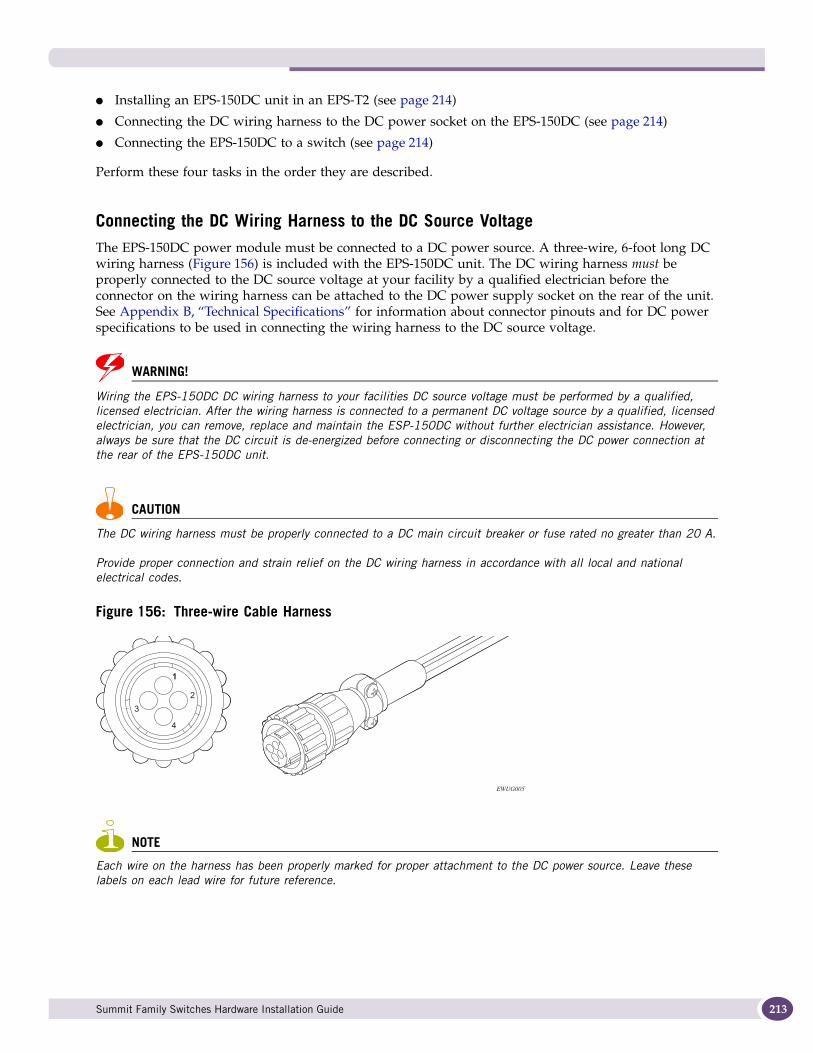
● Installing an EPS-150DC unit in an EPS-T2 (see page 214)
● Connecting the DC wiring harness to the DC power socket on the EPS-150DC (see page 214)
● Connecting the EPS-150DC to a switch (see page 214)
Perform these four tasks in the order they are described.
Connecting the DC Wiring Harness to the DC Source VoltageThe EPS-150DC power module must be connected to a DC power source. A three-wire, 6-foot long DC wiring harness (Figure 156) is included with the EPS-150DC unit. The DC wiring harness must be properly connected to the DC source voltage at your facility by a qualified electrician before the connector on the wiring harness can be attached to the DC power supply socket on the rear of the unit. See Appendix B, “Technical Specifications” for information about connector pinouts and for DC power specifications to be used in connecting the wiring harness to the DC source voltage.
WARNING!
Wiring the EPS-150DC DC wiring harness to your facilities DC source voltage must be performed by a qualified, licensed electrician. After the wiring harness is connected to a permanent DC voltage source by a qualified, licensed electrician, you can remove, replace and maintain the ESP-150DC without further electrician assistance. However, always be sure that the DC circuit is de-energized before connecting or disconnecting the DC power connection at the rear of the EPS-150DC unit.
CAUTION
The DC wiring harness must be properly connected to a DC main circuit breaker or fuse rated no greater than 20 A.
Provide proper connection and strain relief on the DC wiring harness in accordance with all local and national electrical codes.
Figure 156: Three-wire Cable Harness
NOTE
Each wire on the harness has been properly marked for proper attachment to the DC power source. Leave these labels on each lead wire for future reference.
EWUG005
Summit Family Switches Hardware Installation Guide 213
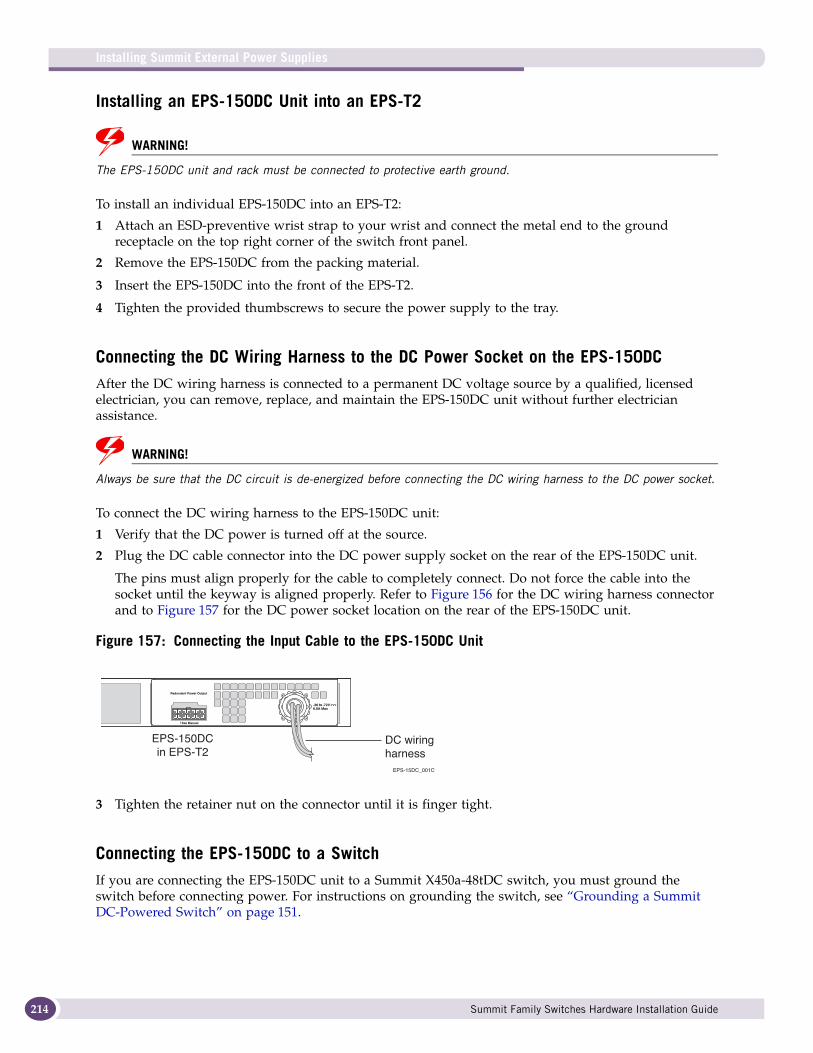
Installing Summit External Power Supplies
214
Installing an EPS-150DC Unit into an EPS-T2
WARNING!
The EPS-150DC unit and rack must be connected to protective earth ground.
To install an individual EPS-150DC into an EPS-T2:
1 Attach an ESD-preventive wrist strap to your wrist and connect the metal end to the ground receptacle on the top right corner of the switch front panel.
2 Remove the EPS-150DC from the packing material.
3 Insert the EPS-150DC into the front of the EPS-T2.
4 Tighten the provided thumbscrews to secure the power supply to the tray.
Connecting the DC Wiring Harness to the DC Power Socket on the EPS-150DCAfter the DC wiring harness is connected to a permanent DC voltage source by a qualified, licensed electrician, you can remove, replace, and maintain the EPS-150DC unit without further electrician assistance.
WARNING!
Always be sure that the DC circuit is de-energized before connecting the DC wiring harness to the DC power socket.
To connect the DC wiring harness to the EPS-150DC unit:
1 Verify that the DC power is turned off at the source.
2 Plug the DC cable connector into the DC power supply socket on the rear of the EPS-150DC unit.
The pins must align properly for the cable to completely connect. Do not force the cable into the socket until the keyway is aligned properly. Refer to Figure 156 for the DC wiring harness connector and to Figure 157 for the DC power socket location on the rear of the EPS-150DC unit.
Figure 157: Connecting the Input Cable to the EPS-150DC Unit
3 Tighten the retainer nut on the connector until it is finger tight.
Connecting the EPS-150DC to a SwitchIf you are connecting the EPS-150DC unit to a Summit X450a-48tDC switch, you must ground the switch before connecting power. For instructions on grounding the switch, see “Grounding a Summit DC-Powered Switch” on page 151.
EPS-15DC_001C
EPS-150DCin EPS-T2
DC wiringharness
Summit Family Switches Hardware Installation Guide
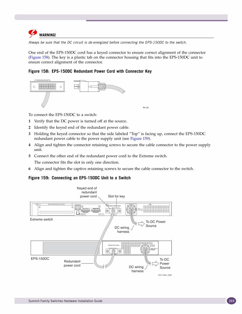
WARNING!
Always be sure that the DC circuit is de-energized before connecting the EPS-150DC to the switch.
One end of the EPS-150DC cord has a keyed connector to ensure correct alignment of the connector (Figure 158). The key is a plastic tab on the connector housing that fits into the EPS-150DC unit to ensure correct alignment of the connector.
Figure 158: EPS-150DC Redundant Power Cord with Connector Key
To connect the EPS-150DC to a switch:
1 Verify that the DC power is turned off at the source.
2 Identify the keyed end of the redundant power cable.
3 Holding the keyed connector so that the side labeled “Top” is facing up, connect the EPS-150DC redundant power cable to the power supply unit (see Figure 159).
4 Align and tighten the connector retaining screws to secure the cable connector to the power supply unit.
5 Connect the other end of the redundant power cord to the Extreme switch.
The connector fits the slot in only one direction.
6 Align and tighten the captive retaining screws to secure the cable connector to the switch.
Figure 159: Connecting an EPS-150DC Unit to a Switch
Collin'sES4K027
XM_055
-48 V2.0 A Max
EPS-150DC_002B
Extreme switch
EPS-150DC
DC wiringharness
Slot for key
To DC PowerSource
To DCPowerSource
Keyed end ofredundant
power cord
DC wiringharness
Redundantpower cord
Summit Family Switches Hardware Installation Guide 215
Installing Summit External Power Supplies
216
7 Energize the DC circuit.
The Power LED on the front of the EPS-150DC unit turns solid green to indicate that it is ready. Table 29 shows the LED meanings for the power supply.
Removing an EPS-150DC Power Module
WARNING!
Always be sure that the DC circuit is de-energized before disconnecting any cables and attempting to remove an EPS-150DC unit.
WARNING!
Removing the DC wiring harness from your facilities DC source voltage requires the performance of a qualified, licensed electrician.
To disconnect and remove an EPS-150DC unit:
1 Attach the ESD strap to your wrist and connect the metal end to the ground receptacle on the top-right corner of the switch front panel.
2 De-energize the DC circuit.
3 Remove power from the EPS-150DC power module by unplugging the DC connector from the DC power supply socket on the rear of the EPS-150DC unit.
Loosen the retainer nut on the DC power connector and unplug the connector from the back of the power unit.
4 At each end of the redundant power cable, unscrew the captive retaining screws on the power connector and disconnect the cable from the switch and the EPS-150DC unit.
5 Loosen the thumbscrews on the front of the EPS-150DC unit until they are completely free of the EPS-T tray, and slide the EPS-150 unit out of the tray.
Installing an EPS-600LS External Power ModuleYou install one, two, or three EPS-600LS power modules (model 10913) in the EPS-C chassis (Model No. 10912) to build an external redundant power system for a Summit PoE-capable switch. A redundant power cable shipped with the EPS-C chassis provides the connection between the external power system and the redundant power input connector on the back of the switch.
Table 30: LED Meanings on the EPS-150DC Power Supply
Power LED Indicates
Green, solid The external power module is operating normally.
Off The external power module is not connected.
Summit Family Switches Hardware Installation Guide
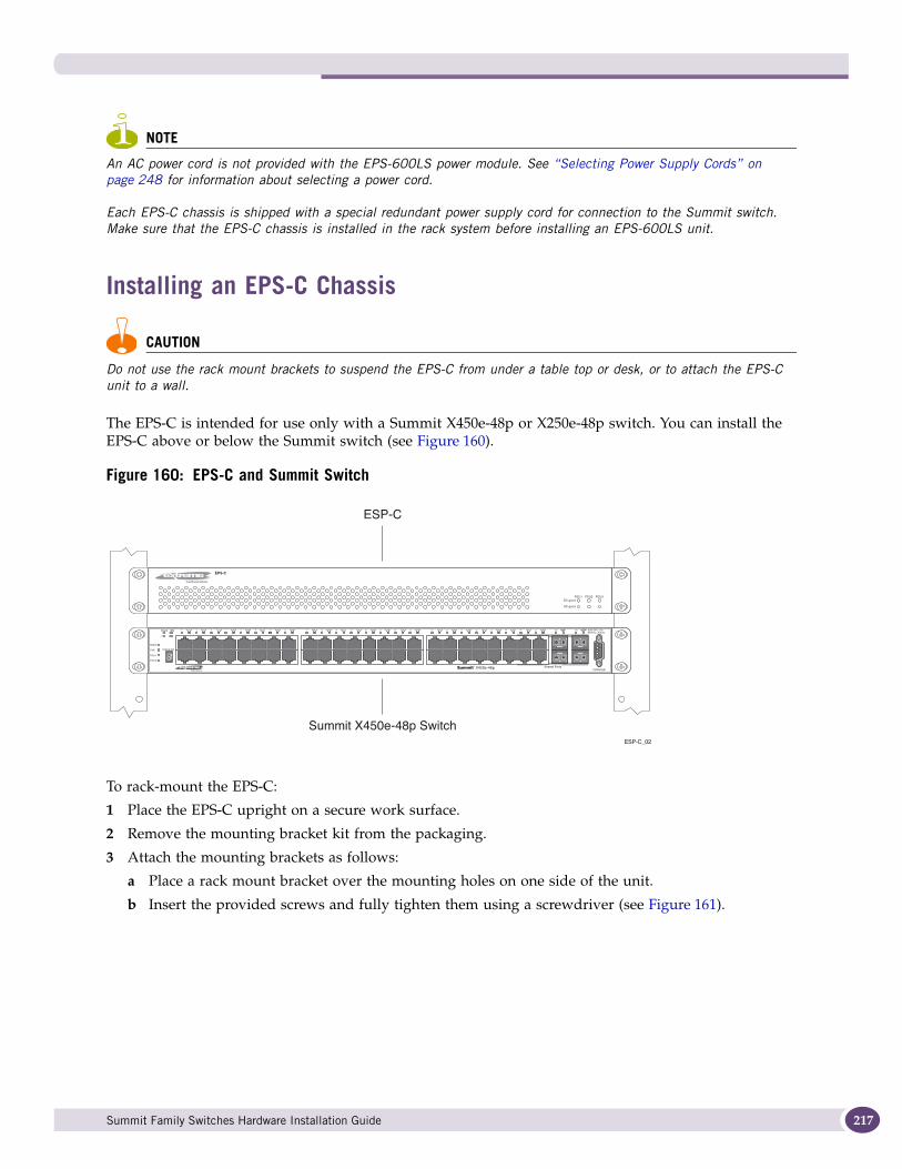
NOTE
An AC power cord is not provided with the EPS-600LS power module. See “Selecting Power Supply Cords” on page 248 for information about selecting a power cord.
Each EPS-C chassis is shipped with a special redundant power supply cord for connection to the Summit switch. Make sure that the EPS-C chassis is installed in the rack system before installing an EPS-600LS unit.
Installing an EPS-C Chassis
CAUTION
Do not use the rack mount brackets to suspend the EPS-C from under a table top or desk, or to attach the EPS-C unit to a wall.
The EPS-C is intended for use only with a Summit X450e-48p or X250e-48p switch. You can install the EPS-C above or below the Summit switch (see Figure 160).
Figure 160: EPS-C and Summit Switch
To rack-mount the EPS-C:
1 Place the EPS-C upright on a secure work surface.
2 Remove the mounting bracket kit from the packaging.
3 Attach the mounting brackets as follows:
a Place a rack mount bracket over the mounting holes on one side of the unit.
b Insert the provided screws and fully tighten them using a screwdriver (see Figure 161).
ESP-C_02
EPS-C
PSU1DC good
AC good
PSU2 PSU3
STACK NO.
Stack 10G
MGMT
FAN
PSU-1
PSU-E
Solid ON = LinkBlinking = Activity
2112
12
43 65 87 109 1211 1413 1615 1817 2019 2221 2423 2625 2827 3029 3231 3433 3635 3837 4039 4241 4443 4645 4847 46X45X 48X47X
Shared Ports
Summit X450e-48p Switch
ESP-C
Summit Family Switches Hardware Installation Guide 217
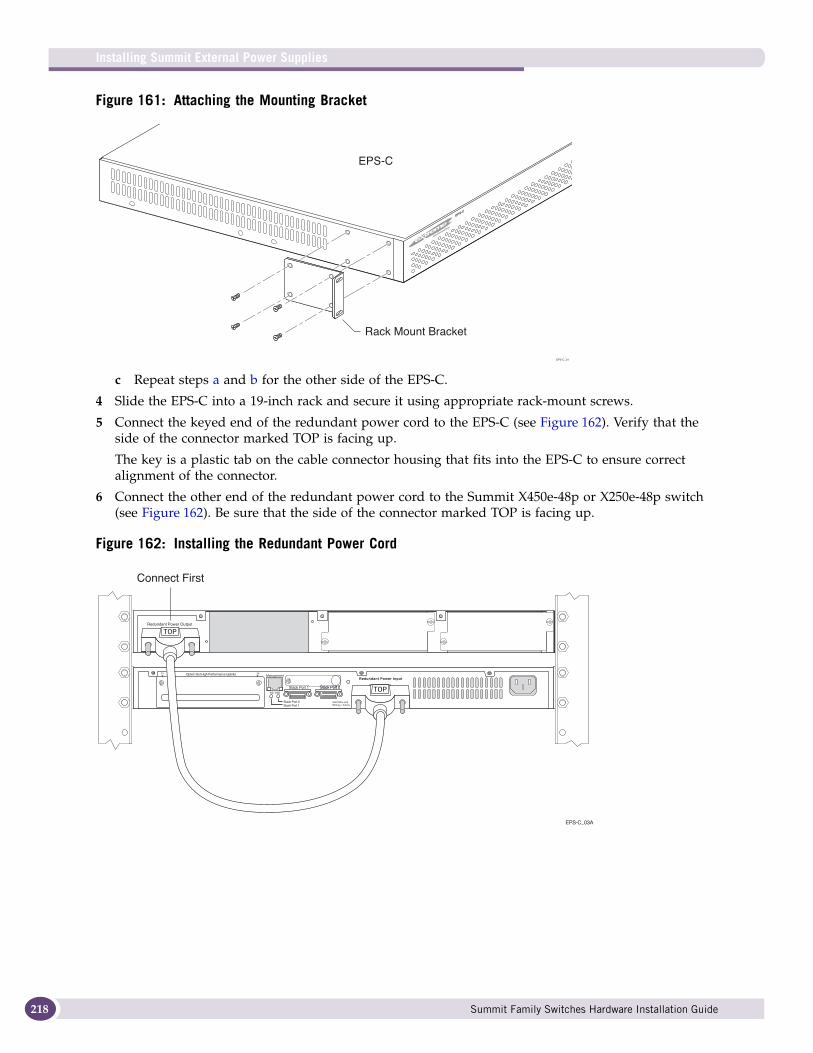
Installing Summit External Power Supplies
218
Figure 161: Attaching the Mounting Bracket
c Repeat steps a and b for the other side of the EPS-C.
4 Slide the EPS-C into a 19-inch rack and secure it using appropriate rack-mount screws.
5 Connect the keyed end of the redundant power cord to the EPS-C (see Figure 162). Verify that the side of the connector marked TOP is facing up.
The key is a plastic tab on the cable connector housing that fits into the EPS-C to ensure correct alignment of the connector.
6 Connect the other end of the redundant power cord to the Summit X450e-48p or X250e-48p switch (see Figure 162). Be sure that the side of the connector marked TOP is facing up.
Figure 162: Installing the Redundant Power Cord
EPS-C
EPS-C_01
Rack Mount Bracket
EPS-C
EPS-C_03A
Redundant Power Output
! See Manual
Connect First
Summit Family Switches Hardware Installation Guide
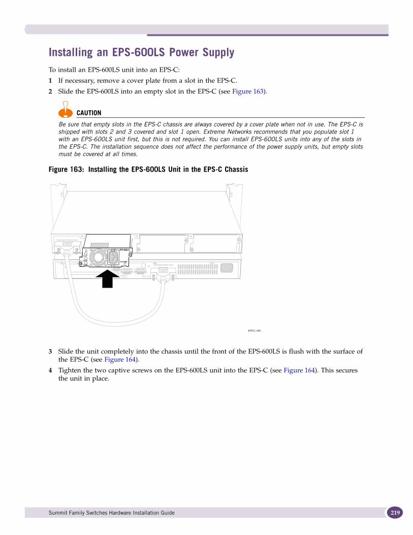
Installing an EPS-600LS Power SupplyTo install an EPS-600LS unit into an EPS-C:
1 If necessary, remove a cover plate from a slot in the EPS-C.
2 Slide the EPS-600LS into an empty slot in the EPS-C (see Figure 163).
CAUTION
Be sure that empty slots in the EPS-C chassis are always covered by a cover plate when not in use. The EPS-C is shipped with slots 2 and 3 covered and slot 1 open. Extreme Networks recommends that you populate slot 1 with an EPS-600LS unit first, but this is not required. You can install EPS-600LS units into any of the slots in the EPS-C. The installation sequence does not affect the performance of the power supply units, but empty slots must be covered at all times.
Figure 163: Installing the EPS-600LS Unit in the EPS-C Chassis
3 Slide the unit completely into the chassis until the front of the EPS-600LS is flush with the surface of the EPS-C (see Figure 164).
4 Tighten the two captive screws on the EPS-600LS unit into the EPS-C (see Figure 164). This secures the unit in place.
EPS-C_04A
! See Manual
O.T.P
DC OK
AC OK
Summit Family Switches Hardware Installation Guide 219
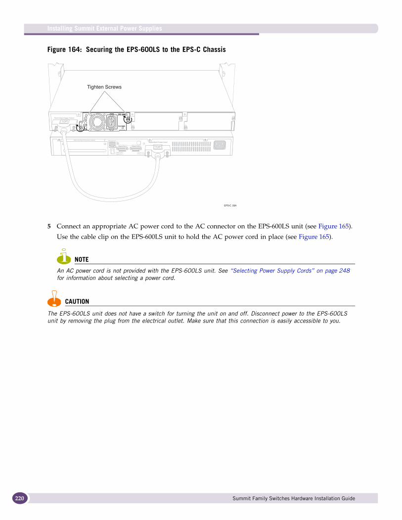
Installing Summit External Power Supplies
220
Figure 164: Securing the EPS-600LS to the EPS-C Chassis
5 Connect an appropriate AC power cord to the AC connector on the EPS-600LS unit (see Figure 165).
Use the cable clip on the EPS-600LS unit to hold the AC power cord in place (see Figure 165).
NOTE
An AC power cord is not provided with the EPS-600LS unit. See “Selecting Power Supply Cords” on page 248 for information about selecting a power cord.
CAUTION
The EPS-600LS unit does not have a switch for turning the unit on and off. Disconnect power to the EPS-600LS unit by removing the plug from the electrical outlet. Make sure that this connection is easily accessible to you.
EPS-C_05A
! See Manual
O.T.P
DC OK
AC OK
EPS-600LS
Tighten Screws
Summit Family Switches Hardware Installation Guide
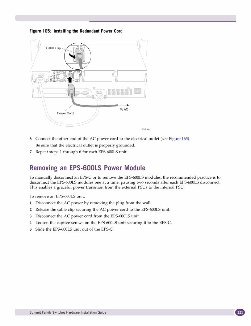
Figure 165: Installing the Redundant Power Cord
6 Connect the other end of the AC power cord to the electrical outlet (see Figure 165).
Be sure that the electrical outlet is properly grounded.
7 Repeat steps 1 through 6 for each EPS-600LS unit.
Removing an EPS-600LS Power ModuleTo manually disconnect an EPS-C or to remove the EPS-600LS modules, the recommended practice is to disconnect the EPS-600LS modules one at a time, pausing two seconds after each EPS-600LS disconnect. This enables a graceful power transition from the external PSUs to the internal PSU.
To remove an EPS-600LS unit:
1 Disconnect the AC power by removing the plug from the wall.
2 Release the cable clip securing the AC power cord to the EPS-600LS unit.
3 Disconnect the AC power cord from the EPS-600LS unit.
4 Loosen the captive screws on the EPS-600LS unit securing it to the EPS-C.
5 Slide the EPS-600LS unit out of the EPS-C.
! See Manual
O.T.P
DC OK
AC OK
EPS-C_06A
To ACPower Cord
Cable Clip
Summit Family Switches Hardware Installation Guide 221

Installing Summit External Power Supplies
222
Summit Family Switches Hardware Installation Guide
7 Summit Option Cards
This chapter describes Summit option cards available for use with Summit X350 series, X450 series, X450a series, and X450e series switches. The chapter includes the following sections
● Overview on page 223● Safety Information on page 224● Summit XGM-2xn Option Card on page 224● Summit XGM2-2xn Option Card on page 225● Summit XGM2-2xf Option Card on page 226● Summit XGM2-2sf Option Card on page 227● Summit XGM2-2bt Option Card on page 227● Installing a Summit Port Option Card on page 228
NOTE
Read the information in this chapter thoroughly before trying install or remove a Summit option card.
OverviewFive types of Summit port option card are available for the Summit X350, X450, X450a, and X450e series switches:
● Summit XGM-2xn option card: Adds one or two 10-gigabit XENPAK optical transceivers to a Summit X450 series switch.
● Summit XGM2-2xn option card: Adds one or two 10-gigabit XENPAK optical transceivers to a Summit X450a series or X450e series switch.
● Summit XGM2-2xf option card: Adds one or two 10-gigabit XFP modules to a Summit X350 series, X450a series or X450e series switch.
● XGM2-2sf option card: Adds one or two 10-Gigabit SFP+ modules to a Summit X350 series, X450a series, or X450e series switch.
● XGM2-2bt option card: adds one or two fixed 10GBASE-T ports to a Summit X350 series, X450a series, or X450e series switch.
These option cards are installed in an option slot on the rear panel of compatible switches. The option slot is covered by a blank panel if the option card is not installed.
Summit Family Switches Hardware Installation Guide 223
Summit Option Cards
224
Safety Information
CAUTION
Pluggable optical modules may become very hot after prolonged use. Take care when removing a pluggable optical module from the option card. If the pluggable optical module is too hot to touch, disengage the module and allow it to cool before removing it completely.
Before installing a Summit option card into your network:
● Read the latest installation and safety information in this chapter and the section specific to the optic type you are installing.
● See Appendix A, “Safety Information,” for additional safety information and Appendix B, “Technical Specifications,” for additional information regarding regulatory compliance certifications.
WARNING!
When working with laser optic modules, always take the following precautions to prevent exposure to hazardous radiation:
● Never look at the transmit LED/laser through a magnifying device while it is powered on.
● Never look directly at a fiber port on the switch or at the ends of a fiber cable when they are powered on.
● Invisible laser radiation can occur when the connectors are open. Avoid direct eye exposure to the beam when optic connections are unplugged.
● Never alter, modify, or change an optic device in any way other than suggested in this document.
Summit XGM-2xn Option CardThe Summit XGM-2xn option card allows you to add up to two 10-gigabit XENPAK modules to the following switches:
● Summit X450-24x switch, running ExtremeXOS 11.2.0 (or later)● Summit X450-24t switch, running ExtremeXOS 11.2.0 (or later)
The Summit XGM-2xn option card is compatible with the following 10-gigabit XENPAK modules:
● SR XENPAK module, operating in the 850 nm range● LR XENPAK module, operating in the 1310 nm range● ER XENPAK module, operating in the 1550 nm range● ZR XENPAK module, operating in the 1550 nm range● LX-4 XENPAK module, operating in the 1269-1355 nm range
For more information about these XENPAK modules, refer to the Extreme Networks Pluggable Interface Modules Installation Guide.
NOTE
The ExtremeXOS software also recognizes standards-based CX-4 XENPAKs; contact your CX-4 module vendor to obtain these.
Summit Family Switches Hardware Installation Guide
Mixing ZR XENPAKs with Other TypesTable 31 lists the supported combinations of XENPAK types using ZR XENPAKs in a Summit X450 series switch. You can either install one ZR XENPAK and leave one slot empty or install one ZR XENPAK and one SR XENPAK; the Summit X450 series switch does not support any other XENPAK combinations when a ZR XENPAK module is installed. You must put the specified modules in the specified slots, as shown in Table 31, for the switch to discover the ZR XENPAK correctly..
Summit XGM2-2xn Option CardThe Summit XGM2-2xn option card allows you to add up to two 10-gigabit XENPAK modules to the following switches:
● Summit X450a-24t switch, running ExtremeXOS 11.5.0 (or later)● Summit X450a-24tDC switch, running ExtremeXOS 11.5.0 (or later)● Summit X450a-24x switch, running ExtremeXOS 11.6.1 (or later)● Summit X450a-24xDC switch, running ExtremeXOS 11.6.1 (or later)● Summit X450a-48t switch, running ExtremeXOS 11.5.0 (or later)● Summit X450e-24p switch, running ExtremeXOS 11.5.0 (or later)● Summit X450e-48p switch, running ExtremeXOS 11.6.1 (or later)
The Summit XGM2-2xn option card is compatible with the following 10-gigabit XENPAK modules:
● SR XENPAK module, operating in the 850 nm range● LR XENPAK module, operating in the 1310 nm range● ER XENPAK module, operating in the 1550 nm range● ZR XENPAK module, operating in the 1550 nm range● LX-4 XENPAK module, operating in the 1269-1355 nm range● LW XENPAK module, operating in the 1310 nm range
Figure 166 shows the Summit XGM2-2xn option card.
Table 31: Summit X450 ZR XENPAK Combinations
Left Slot Right Slot
ZR XENPAK Empty
ZR XENPAK SR XENPAK
Summit Family Switches Hardware Installation Guide 225

Summit Option Cards
226
Figure 166: Summit XGM2-2xn Option Card
NOTE
Refer to the Extreme Networks Pluggable Interface Modules Installation Guide for more information about XENPAK modules.
Standards-based CX-4 XENPAKs are also recognized by ExtremeXOS; contact your CX-4 module vendor to obtain these.
Summit XGM2-2xf Option CardThe Summit XGM2-2xf option card allows you to add up to two 10-gigabit XFP modules to the following switches:
● Summit X450a-24t switch, running ExtremeXOS 11.5.0 (or later)● Summit X450a-24tDC switch, running ExtremeXOS 11.5.0 (or later)● Summit X450a-24x switch, running ExtremeXOS 11.6.1 (or later)● Summit X450a-24xDC switch, running ExtremeXOS 11.6.1 (or later)● Summit X450a-48t switch, running ExtremeXOS 11.5.0 (or later)● Summit X450e-24p switch, running ExtremeXOS 11.5.0 (or later)● Summit X450e-48p switch, running ExtremeXOS 11.6.1 (or later)
The Summit XGM2-2xf option card is compatible with the following 10-gigabit XFP modules:
● LR XFP module● SR XFP module
Figure 167 shows the Summit XGM2-2xf option card.
SH_010
Summit Family Switches Hardware Installation Guide
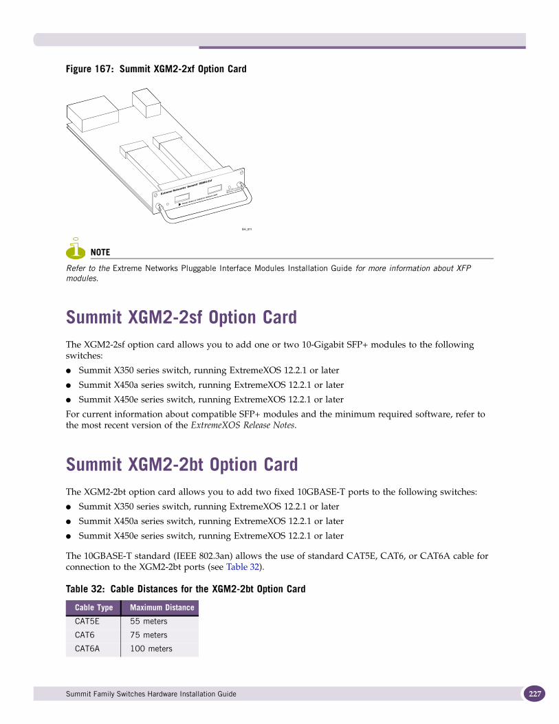
Figure 167: Summit XGM2-2xf Option Card
NOTE
Refer to the Extreme Networks Pluggable Interface Modules Installation Guide for more information about XFP modules.
Summit XGM2-2sf Option CardThe XGM2-2sf option card allows you to add one or two 10-Gigabit SFP+ modules to the following switches:
● Summit X350 series switch, running ExtremeXOS 12.2.1 or later
● Summit X450a series switch, running ExtremeXOS 12.2.1 or later
● Summit X450e series switch, running ExtremeXOS 12.2.1 or later
For current information about compatible SFP+ modules and the minimum required software, refer to the most recent version of the ExtremeXOS Release Notes.
Summit XGM2-2bt Option CardThe XGM2-2bt option card allows you to add two fixed 10GBASE-T ports to the following switches:
● Summit X350 series switch, running ExtremeXOS 12.2.1 or later
● Summit X450a series switch, running ExtremeXOS 12.2.1 or later
● Summit X450e series switch, running ExtremeXOS 12.2.1 or later
The 10GBASE-T standard (IEEE 802.3an) allows the use of standard CAT5E, CAT6, or CAT6A cable for connection to the XGM2-2bt ports (see Table 32).
Table 32: Cable Distances for the XGM2-2bt Option Card
Cable Type Maximum Distance
CAT5E 55 meters
CAT6 75 meters
CAT6A 100 meters
SH_011
Summit Family Switches Hardware Installation Guide 227
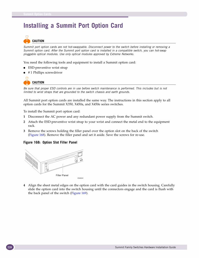
Summit Option Cards
228
Installing a Summit Port Option Card
CAUTION
Summit port option cards are not hot-swappable. Disconnect power to the switch before installing or removing a Summit option card. After the Summit port option card is installed in a compatible switch, you can hot-swap pluggable optical modules. Use only optical modules approved by Extreme Networks.
You need the following tools and equipment to install a Summit option card:
● ESD-preventive wrist strap● # 1 Phillips screwdriver
CAUTION
Be sure that proper ESD controls are in use before switch maintenance is performed. This includes but is not limited to wrist straps that are grounded to the switch chassis and earth grounds.
All Summit port option cards are installed the same way. The instructions in this section apply to all option cards for the Summit X350, X450a, and X450e series switches.
To install the Summit port option card:
1 Disconnect the AC power and any redundant power supply from the Summit switch.
2 Attach the ESD-preventive wrist strap to your wrist and connect the metal end to the equipment rack.
3 Remove the screws holding the filler panel over the option slot on the back of the switch (Figure 168). Remove the filler panel and set it aside. Save the screws for re-use.
Figure 168: Option Slot Filler Panel
4 Align the sheet metal edges on the option card with the card guides in the switch housing. Carefully slide the option card into the switch housing until the connectors engage and the card is flush with the back panel of the switch (Figure 169).
ES4K041
Filler Panel
Summit Family Switches Hardware Installation Guide
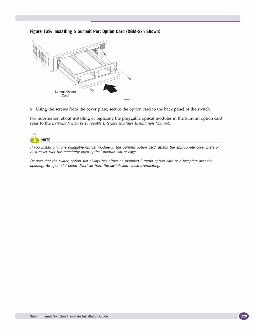
Figure 169: Installing a Summit Port Option Card (XGM-2xn Shown)
5 Using the screws from the cover plate, secure the option card to the back panel of the switch.
For information about installing or replacing the pluggable optical modules in the Summit option card, refer to the Extreme Networks Pluggable Interface Modules Installation Manual.
NOTE
If you install only one pluggable optical module in the Summit option card, attach the appropriate cover plate or dust cover over the remaining open optical module slot or cage.
Be sure that the switch option slot always has either an installed Summit option card or a faceplate over the opening. An open slot could divert air from the switch and cause overheating.
ES4K042
Summit Option
Card
Summit Family Switches Hardware Installation Guide 229

Summit Option Cards
230
Summit Family Switches Hardware Installation Guide
8 Maintenance Procedures for Summit X650 and Summit X480 Series Switches
This chapter describes how to replace components in a Summit X650 series switch. This chapter includes the following sections:
● Replacing a Summit X650 AC PSU on page 231● Replacing a Summit X650 DC Power Supply on page 234● Replacing a Summit X480/X650 Fan Module on page 239● Replacing a Versatile Interface Module (VIM) on page 240
NOTE
Read the information in this chapter thoroughly before attempting to replace one of the listed Summit X650 components.
Replacing a Summit X650 AC PSUIn a redundant power configuration, you can replace one Summit X650 AC PSU without powering down the switch.
You need the following tools and materials to replace a Summit X650 AC PSU:
● ESD-preventive wrist strap● Thermal protective gloves● AC power cord, if you will not be re-using the cord from the removed power supply
An AC power cord is not included with the Summit X650 AC PSU. You must obtain a power supply cord that meets the requirements listed under “Selecting Power Supply Cords” on page 248.
To replace a Summit X650 AC PSU:
1 Attach an ESD-preventive wrist strap to your bare wrist and connect the metal end to an appropriate grounding point.
2 Disconnect the AC power cord from the wall outlet and from the PSU.
3 Push the latching tab to the left as you pull outward on the handle to disengage the PSU internal connectors (see Figure 170).
Summit Family Switches Hardware Installation Guide 231
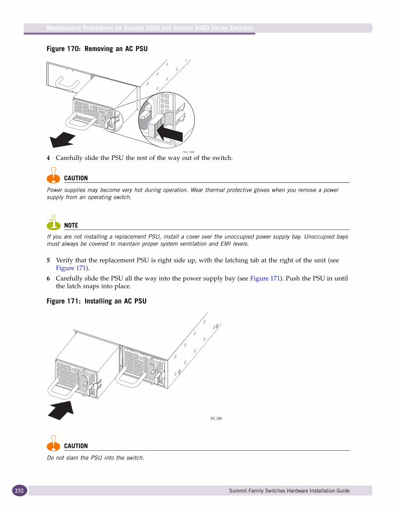
Maintenance Procedures for Summit X650 and Summit X480 Series Switches
232
Figure 170: Removing an AC PSU
4 Carefully slide the PSU the rest of the way out of the switch.
CAUTION
Power supplies may become very hot during operation. Wear thermal protective gloves when you remove a power supply from an operating switch.
NOTE
If you are not installing a replacement PSU, install a cover over the unoccupied power supply bay. Unoccupied bays must always be covered to maintain proper system ventilation and EMI levels.
5 Verify that the replacement PSU is right side up, with the latching tab at the right of the unit (see Figure 171).
6 Carefully slide the PSU all the way into the power supply bay (see Figure 171). Push the PSU in until the latch snaps into place.
Figure 171: Installing an AC PSU
CAUTION
Do not slam the PSU into the switch.
SH 096
SH_089
Summit Family Switches Hardware Installation Guide

7 Connect the power cord to the PSU and to a grounded AC power outlet.
WARNING!
Always be sure that the source outlet is properly grounded before plugging the AC power cord into the AC PSU.
Summit Family Switches Hardware Installation Guide 233
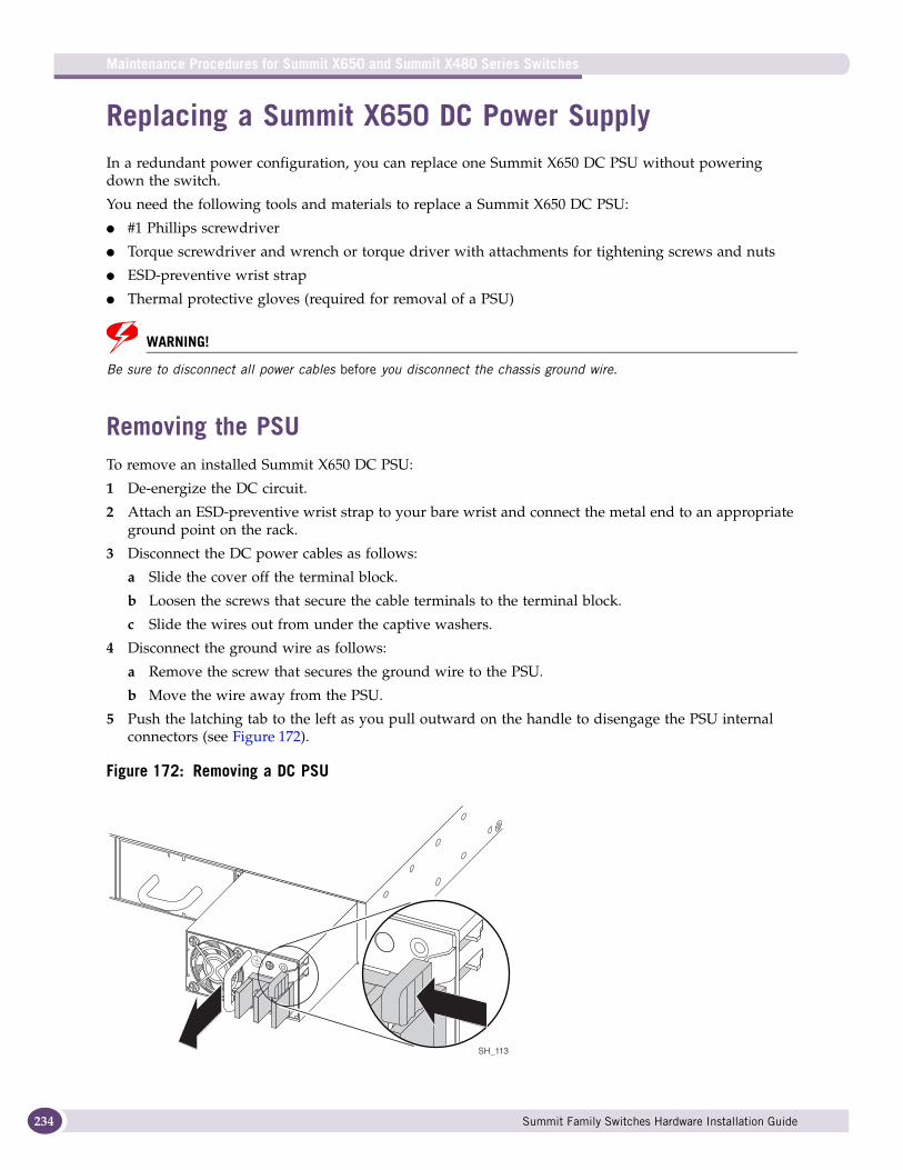
Maintenance Procedures for Summit X650 and Summit X480 Series Switches
234
Replacing a Summit X650 DC Power SupplyIn a redundant power configuration, you can replace one Summit X650 DC PSU without powering down the switch.
You need the following tools and materials to replace a Summit X650 DC PSU:
● #1 Phillips screwdriver
● Torque screwdriver and wrench or torque driver with attachments for tightening screws and nuts
● ESD-preventive wrist strap
● Thermal protective gloves (required for removal of a PSU)
WARNING!
Be sure to disconnect all power cables before you disconnect the chassis ground wire.
Removing the PSUTo remove an installed Summit X650 DC PSU:
1 De-energize the DC circuit.
2 Attach an ESD-preventive wrist strap to your bare wrist and connect the metal end to an appropriate ground point on the rack.
3 Disconnect the DC power cables as follows:
a Slide the cover off the terminal block.
b Loosen the screws that secure the cable terminals to the terminal block.
c Slide the wires out from under the captive washers.
4 Disconnect the ground wire as follows:
a Remove the screw that secures the ground wire to the PSU.
b Move the wire away from the PSU.
5 Push the latching tab to the left as you pull outward on the handle to disengage the PSU internal connectors (see Figure 172).
Figure 172: Removing a DC PSU
SH_113
Summit Family Switches Hardware Installation Guide
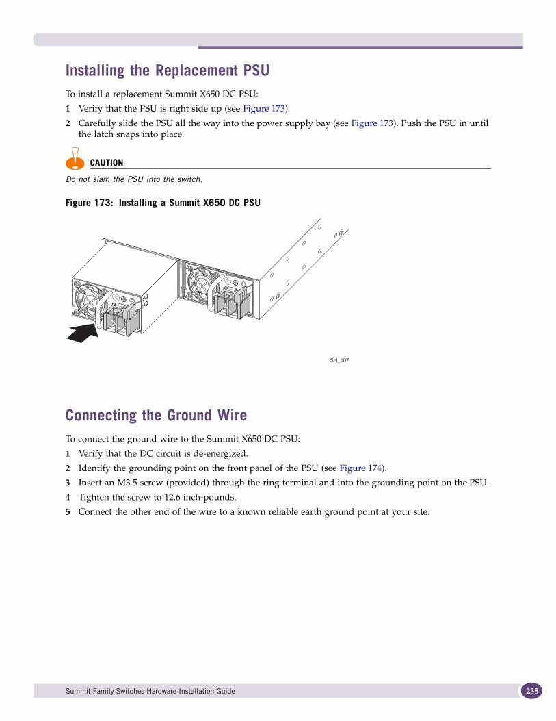
Installing the Replacement PSUTo install a replacement Summit X650 DC PSU:
1 Verify that the PSU is right side up (see Figure 173)
2 Carefully slide the PSU all the way into the power supply bay (see Figure 173). Push the PSU in until the latch snaps into place.
CAUTION
Do not slam the PSU into the switch.
Figure 173: Installing a Summit X650 DC PSU
Connecting the Ground WireTo connect the ground wire to the Summit X650 DC PSU:
1 Verify that the DC circuit is de-energized.
2 Identify the grounding point on the front panel of the PSU (see Figure 174).
3 Insert an M3.5 screw (provided) through the ring terminal and into the grounding point on the PSU.
4 Tighten the screw to 12.6 inch-pounds.
5 Connect the other end of the wire to a known reliable earth ground point at your site.
SH_107
Summit Family Switches Hardware Installation Guide 235
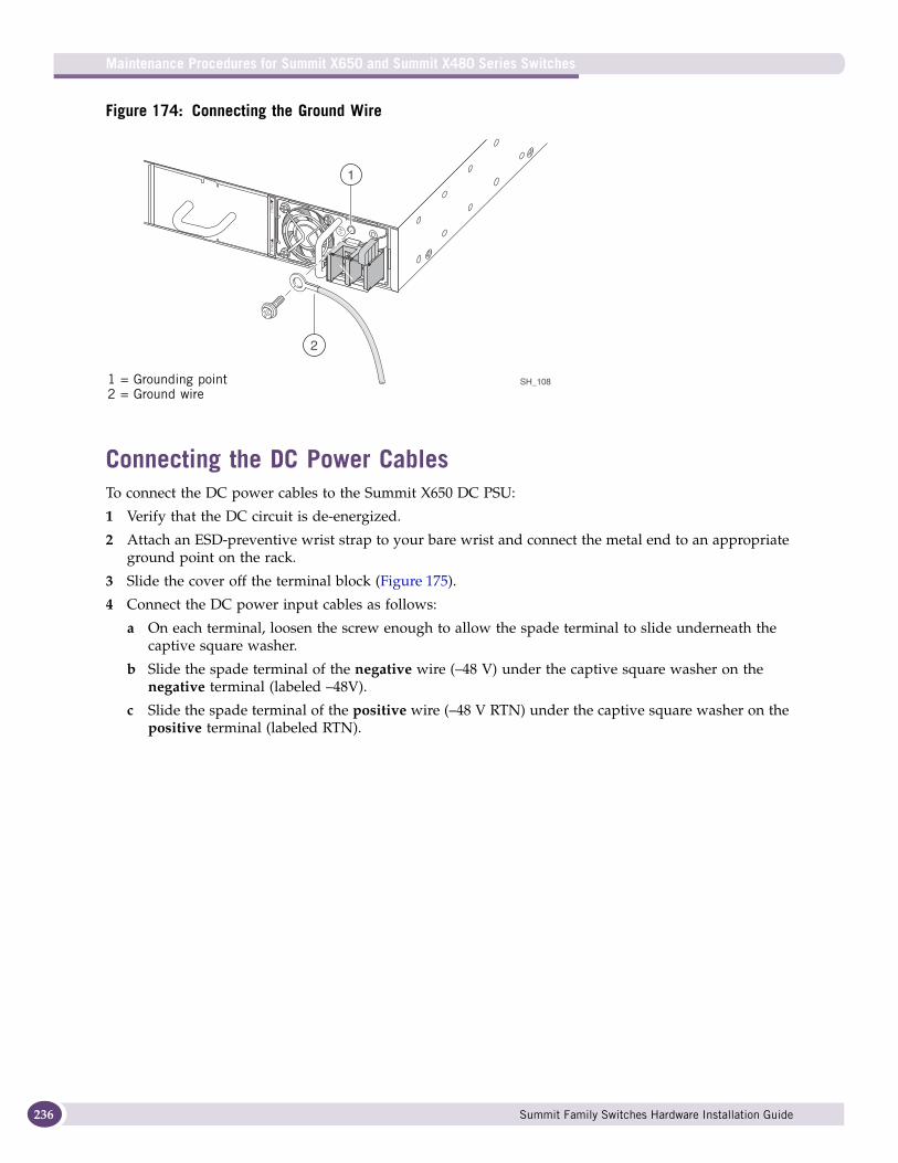
Maintenance Procedures for Summit X650 and Summit X480 Series Switches
236
Figure 174: Connecting the Ground Wire
Connecting the DC Power CablesTo connect the DC power cables to the Summit X650 DC PSU:
1 Verify that the DC circuit is de-energized.
2 Attach an ESD-preventive wrist strap to your bare wrist and connect the metal end to an appropriate ground point on the rack.
3 Slide the cover off the terminal block (Figure 175).
4 Connect the DC power input cables as follows:
a On each terminal, loosen the screw enough to allow the spade terminal to slide underneath the captive square washer.
b Slide the spade terminal of the negative wire (–48 V) under the captive square washer on the negative terminal (labeled –48V).
c Slide the spade terminal of the positive wire (–48 V RTN) under the captive square washer on the positive terminal (labeled RTN).
SH_108
1
2
1 = Grounding point2 = Ground wire
Summit Family Switches Hardware Installation Guide
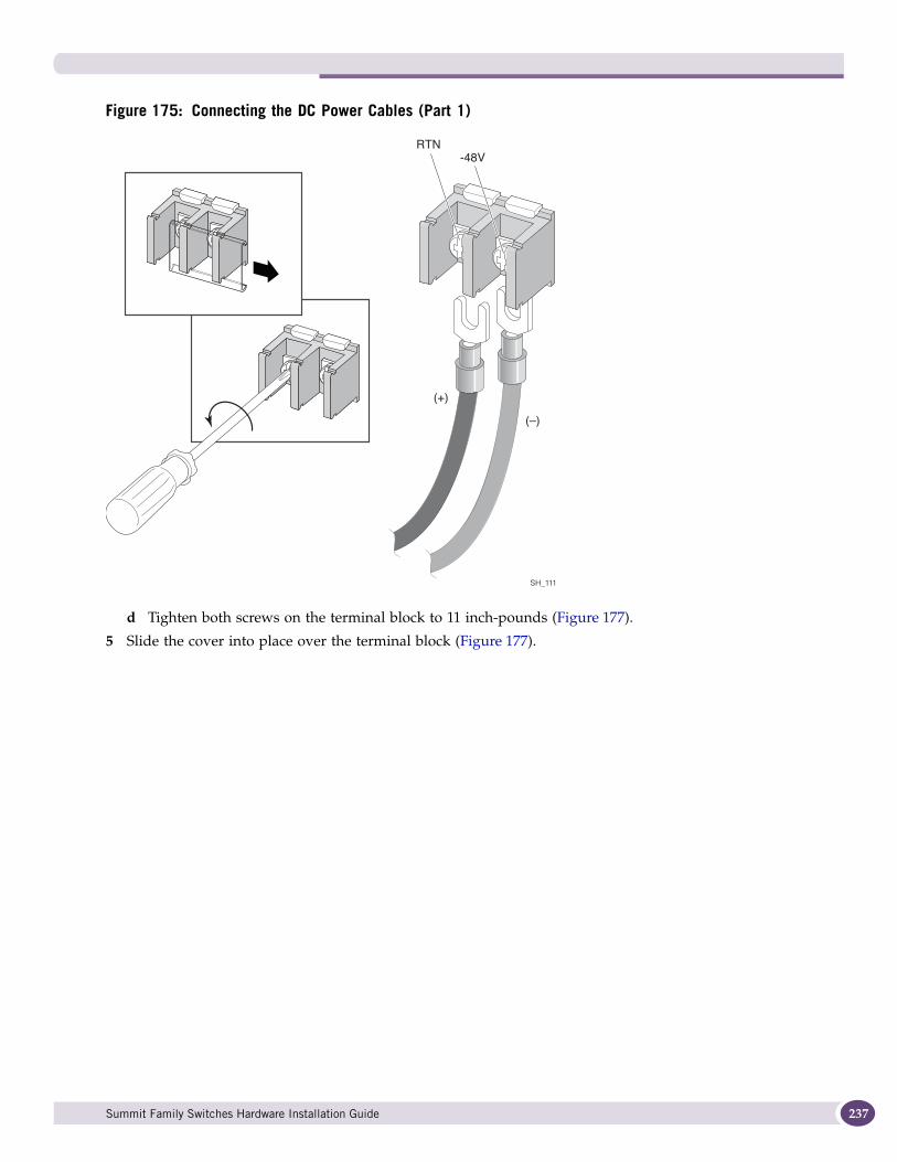
Figure 175: Connecting the DC Power Cables (Part 1)
d Tighten both screws on the terminal block to 11 inch-pounds (Figure 177).
5 Slide the cover into place over the terminal block (Figure 177).
(+)
(–)
RTN-48V
SH_111
Summit Family Switches Hardware Installation Guide 237

Maintenance Procedures for Summit X650 and Summit X480 Series Switches
238
Figure 176: Connecting the DC Power Cables (Part 2)
6 Energize the DC circuit.
SH_112
(+)
(–)
RTN -48V
Summit Family Switches Hardware Installation Guide
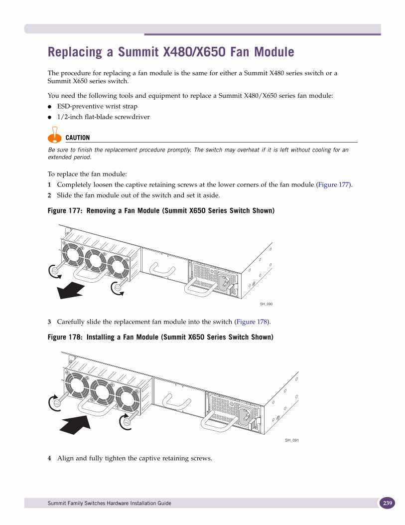
Replacing a Summit X480/X650 Fan ModuleThe procedure for replacing a fan module is the same for either a Summit X480 series switch or a Summit X650 series switch.
You need the following tools and equipment to replace a Summit X480/X650 series fan module:
● ESD-preventive wrist strap
● 1/2-inch flat-blade screwdriver
CAUTION
Be sure to finish the replacement procedure promptly. The switch may overheat if it is left without cooling for an extended period.
To replace the fan module:
1 Completely loosen the captive retaining screws at the lower corners of the fan module (Figure 177).
2 Slide the fan module out of the switch and set it aside.
Figure 177: Removing a Fan Module (Summit X650 Series Switch Shown)
3 Carefully slide the replacement fan module into the switch (Figure 178).
Figure 178: Installing a Fan Module (Summit X650 Series Switch Shown)
4 Align and fully tighten the captive retaining screws.
SH_090
SH_091
Summit Family Switches Hardware Installation Guide 239
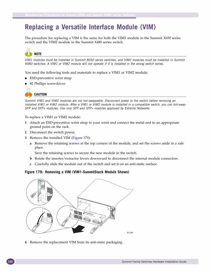
Maintenance Procedures for Summit X650 and Summit X480 Series Switches
240
Replacing a Versatile Interface Module (VIM)The procedure for replacing a VIM is the same for both the VIM1 module in the Summit X650 series switch and the VIM2 module in the Summit X480 series switch.
NOTE
VIM1 modules must be installed in Summit X650 series switches, and VIM2 modules must be installed in Summit X480 switches. A VIM1 or VIM2 module will not operate if it is installed in the wrong switch series.
You need the following tools and materials to replace a VIM1 or VIM2 module:
● ESD-preventive wrist strap
● #2 Phillips screwdriver
CAUTION
Summit VIM1 and VIM2 modules are not hot-swappable. Disconnect power to the switch before removing an installed VIM1 or VIM2 module. After a VIM1 or VIM2 module is installed in a compatible switch, you can hot-swap SFP and SFP+ modules. Use only SFP and SFP+ modules approved by Extreme Networks.
To replace a VIM1 or VIM2 module:
1 Attach an ESD-preventive wrist strap to your wrist and connect the metal end to an appropriate ground point on the rack.
2 Disconnect the switch power.
3 Remove the installed VIM (Figure 179):
a Remove the retaining screws at the top corners of the module, and set the screws aside in a safe place.
Save the retaining screws to secure the new module in the switch.
b Rotate the inserter/extractor levers downward to disconnect the internal module connectors.
c Carefully slide the module out of the switch and set it on an anti-static surface.
Figure 179: Removing a VIM (VIM1-SummitStack Module Shown)
4 Remove the replacement VIM from its anti-static packaging.
SH_092
Summit Family Switches Hardware Installation Guide
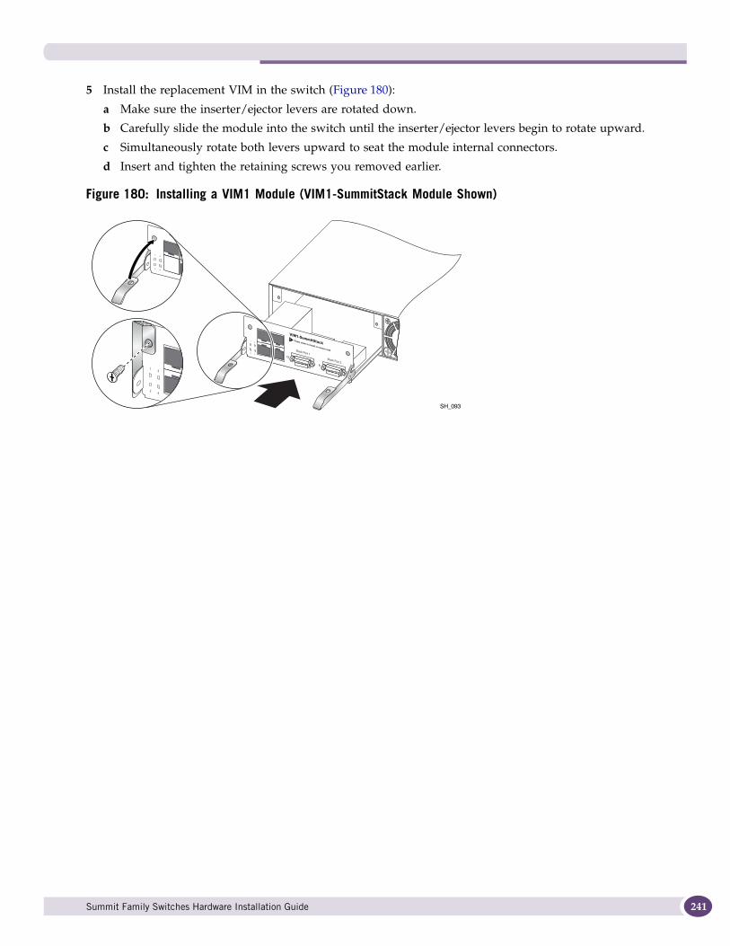
5 Install the replacement VIM in the switch (Figure 180):
a Make sure the inserter/ejector levers are rotated down.
b Carefully slide the module into the switch until the inserter/ejector levers begin to rotate upward.
c Simultaneously rotate both levers upward to seat the module internal connectors.
d Insert and tighten the retaining screws you removed earlier.
Figure 180: Installing a VIM1 Module (VIM1-SummitStack Module Shown)
SH_093
Summit Family Switches Hardware Installation Guide 241

Maintenance Procedures for Summit X650 and Summit X480 Series Switches
242
Summit Family Switches Hardware Installation Guide
3 Appendices

A Safety Information
WARNING!
Read the following safety information thoroughly before installing Extreme Networks products. Failure to follow this safety information can lead to personal injury or damage to the equipment.
Only trained service personnel should perform service to Extreme Networks switches and their components. Trained service personnel have read all related installation manuals, have the technical training and experience necessary to be aware of the hazards to which they are exposed in performing a task, and are aware of measures to minimize the danger to themselves or other persons.
This appendix includes the following sections:
● Considerations Before Installing on page 245
● Installing External Power Supply Units on page 246
● Maintenance Safety on page 247
● General Safety Precautions on page 247
● Cable Routing for LAN Systems on page 247
● Selecting Power Supply Cords on page 248
● Battery Replacement and Disposal on page 249
● Fiber Optic Ports—Optical Safety on page 249
Considerations Before InstallingConsider the following items before installing equipment.
● The system is designed to operate in a typical environmentally controlled Telco environment. Choose an indoor area that has the following characteristics:
■ Temperature- and humidity-controlled, such that the maximum ambient room temperature shall not exceed 40ºC (104ºF)
■ Clean and free from airborne materials that can conduct electricity
■ Well ventilated and away from sources of heat including direct sunlight
■ Away from sources of vibration or physical shock
■ Isolated from strong electromagnetic fields produced by electrical devices
■ Secured, enclosed, and restricted-access, ensuring that only trained and qualified service personnel have access to the equipment
● Establish at least 3 inches clearance on all sides for effective ventilation. Do not obstruct the air intake vent on the front, side, or rear ventilation grills. Locate the system away from heat sources.
● Make sure that your equipment is placed in an area that accommodates the power consumption and component heat dissipation specifications.
● Make sure that your power supplies meet the site power or AC power requirements of the all network equipment.
Summit Family Switches Hardware Installation Guide 245

Safety Information
246
Installing External Power Supply UnitsFor the ratings and power requirements of each power supply unit, see Appendix B, “Technical Specifications” or the data sheet for the power supply at http://www.extremenetworks.com.
WARNING!
Be sure that the requirements listed in this section are satisfied when installing all Extreme Networks power supplies.
When you install external power supplies:
● Plug power supplies only into properly grounded electrical outlets to help prevent electrical shock and comply with international safety standards.
● Use only power cords that are certified for use within the country of use. Do not attempt to modify AC power cords.
● Make sure the wall outlet is installed near the equipment and is easily accessible for quick disconnect.
● Make sure the voltage and frequency of your power outlet match the system electrical ratings for the equipment. The building and/or power source must provide overload protection.
● Use a surge suppressor, line conditioner, or uninterruptible power supply to protect the system from momentary increases or decreases in electrical power.
● When inserting a power supply into the bay, do not use excessive force.
● If multiple power supplies are used with a switch, connect each power supply to a different, independent power source. If a single power source fails, it will affect only that power supply to which it is connected. If all the power supplies on a single switch are connected to the same power source, the entire switch is vulnerable to a power failure.
WARNING!
Wiring a DC power cord to your facility DC source voltage must be performed by a qualified, licensed electrician.
Extreme Networks AC external power supplies do not have switches for turning the unit on and off. Remove the wall plug from the electrical outlet to disconnect the power from an Extreme Networks AC external power supply. Make sure that this connection is easily accessible.
Do not connect an EPS-600LS power supply to an electrical outlet when the power supply is not installed in the EPS-C chassis; doing so would expose a hazardous energy and poses a potential shock and fire hazard.
Do not put your hand into an open power supply bay when a power supply is not present. Empty power supply bays require a cover plate at all times.
Summit Family Switches Hardware Installation Guide
Maintenance SafetyWhen you perform maintenance procedures on Extreme Networks equipment, follow these recommendations:
● Use only original accessories or components approved for use with this system. Failure to follow these instructions may damage the equipment or violate required safety and EMC regulations.
● The chassis cover should only be removed by Extreme Networks personnel. This system contains no customer serviceable components. Repairs to the system must be performed by an Extreme Networks factory service technician.
● In systems that have power-on buttons, the power on button may not turn off all system power. To remove power from the system, you must unplug all power cords from wall outlets. The power cord is the disconnect device to the main power source.
● Disconnect all power cords before working near power supplies, unless otherwise instructed by a maintenance procedure.
● Replace a power cord immediately if it shows any signs of damage.
● When you work with optical devices, power supplies, or other modular accessories, put on an ESD-preventive wrist strap to reduce the risk of electronic damage to the equipment. Connect the other end of the strap to an appropriate grounding point on the equipment rack. Leave the ESD-preventive wrist strap permanently attached to the equipment rack so that it is always available when you need to handle ESD-sensitive components.
● Install all cables in a manner that avoids strain. Use tie wraps or other strain relief devices.
General Safety PrecautionsFollow these guidelines:
● Do not try to lift objects that you think are too heavy for you.
● When you install equipment in a rack, load heavier devices in the lower half of the rack first to avoid making the rack top-heavy.
● For Summit desktop equipment installations, do not place a monitor or other objects on top of the equipment. The chassis cover is not designed to support weight.
● Only use tools and equipment that are in perfect condition. Do not use equipment with visible damage.
● Route cables in a manner that prevents possible damage to the cables and avoids causing accidents, such as tripping.
Cable Routing for LAN SystemsThe Summit family switches meet the requirements for LAN system equipment. LAN systems are designed only for intra-building installations; that is, cable runs between devices must be in the same building as the connected units.
Summit Family Switches Hardware Installation Guide 247
Safety Information
248
This equipment can be connected between buildings if any one of the following conditions is true:
● Cable runs between buildings are less then 140 feet long.
● Cable runs between buildings are directly buried.
● Cable runs between buildings are in an underground conduit, where a continuous metallic cable shield or a continuous metallic conduit containing the cable is bonded to each building grounding electrode system.
CAUTION
Failure follow these requirements for cable routing conditions may expose the user to electrical shock and expose the unit to errors or damage.
WARNING!
The intra-building ports of the equipment or subassembly are suitable for connection to intrabuilding or unexposed wiring or cabling only. The intra-building port(s) of the equipment or subassembly MUST NOT be metallically connected to interfaces that connect to the outside plant (OSP) or its wiring. These interfaces are designed for use as intra-building interfaces only (Type 2 or Type 4 ports as described in GR-1089-CORE, Issue 4) and require isolation from the exposed OSP cabling. The addition of Primary Protectors is not sufficient protection in order to connect these interfaces metallically to OSP wiring.
PoE DevicesWhen connecting power over Ethernet (PoE) devices to a PoE switch, all connections between the PoE device and the switch must remain inside the same building and use a low-voltage power distribution system per IEEE 802.3af.
Selecting Power Supply CordsExtreme Networks does not include power input cords in the product box. To purchase a power cord for your product and for your specific country, contact your local Extreme Networks Channel Account Manager or Sales Manager, or purchase a cord from your local supplier.
To locate a Sales Manager or Partner in your region visit:
http://www.extremenetworks.com/how-to-buy/how-to-buy.aspx
The following are requirements for power cords used on AC-powered Summit family switches and compatible external power supplies:
● The power cord must be agency-certified for the country of use.
● The power cord must have an IEC320-C13 connector for connection to the switch or external power supply.
● The power cord must have an appropriately rated and approved wall plug applicable to the country of installation.
● For cords up to 6 feet (2 m) long, the wire size must be 18 AWG (.75 mm2) minimum; over 6 feet, the minimum wire size is 16 AWG (1.0 mm2).
Summit Family Switches Hardware Installation Guide
WARNING!
When using multiple power supplies, make sure that each power supply is attached to an independent circuit breaker. See the installation instructions for the power supply for proper sizing of circuit breaker.
Make sure that the source outlet is properly grounded according to the country’s local electrical requirements before plugging the AC supply power cord into a power supply.
For specific product input power requirements refer to the data sheet of the product or modular power supply at http://www.extremenetworks.com or to Appendix B of this guide.
NOTE
This equipment is not intended to be directly powered by power distribution systems where phase-phase voltages exceed 240V AC (2P+PE), such as those used in Norway, France, and other countries. For these applications it is recommended that a transformer be used to step down the voltage to < 240V AC from phase-phase, or that you make a connection to a (P+N+PE) power distribution where voltages do not exceed 240V AC.
All installations should confirm that the product is reliably grounded according to the country’s local electrical codes.
NOTE
Building codes vary worldwide; therefore, Extreme Networks strongly recommends that you consult an electrical contractor to ensure proper equipment grounding and power distribution for your specific installation & country.
Battery Replacement and DisposalBatteries included with Extreme products are encapsulated and must be replaced by qualified Extreme Service personnel only. Contact your Extreme Service personnel for product replacement. Do not attempt to replace the battery. If these instructions are disregarded and replacement of these batteries is attempted, the following guidelines must be followed to avoid danger of explosion:
● Replace with the same or equivalent battery type as recommended by the battery manufacturer.
● Dispose of the battery in accordance with the battery manufacturer’s recommendation.
Fiber Optic Ports—Optical SafetyThe following safety warnings apply to all optical devices used in Extreme Networks equipment that are removable or directly installed in an I/O module or chassis system. Such devices include but are not limited to gigabit interface converters (GBICs), small form factor pluggable (SFP) modules (or mini-GBICs), XENPAK transceivers, and XFP laser optic modules.
WARNING!
Laser optic modules become very hot after prolonged use. Be careful when removing a laser optic module from the chassis or option card. If the laser optic module is too hot to touch, disengage the laser optic module and allow it to cool before removing it completely.
Summit Family Switches Hardware Installation Guide 249

Safety Information
250
WARNING!
When working with laser optic modules, always take the following precautions to avoid exposure to hazardous radiation.
● Never look at the transmit LED/laser through a magnifying device while it is powered on.
● Never look directly at a fiber port on the switch or at the ends of a fiber cable when they are powered on.
● Invisible laser radiation can occur when the connectors are open. Avoid direct eye exposure to the beam when optical connections are unplugged.
● Never alter, modify, or change an optical device in any way other than suggested in this document.
SFP (Mini-GBIC), XENPAK, and XFP Regulatory ComplianceExtreme Networks pluggable optical modules meet the following regulatory requirements:
● Class 1 Laser Product
● EN60825-1+A2:2001 or later, European laser standard
● FCC 21 CFR Chapter 1, Subchapter J in accordance with FDA & CDRH requirements
● Application of CE Mark in accordance with 89/336/EEC EMC and 73/23/EEC Low Voltage Directives
● UL and/or CSA registered component for North America
● 47 CFR Part 15, Class A when installed into Extreme products
NOTE
Extreme Networks optical modules are tested to work in all supported Extreme Networks switches. We recommend that all customers use Extreme Networks optical modules in their Extreme Networks switches. Extreme Networks assumes no liability for third-party optical modules. Although Extreme Networks does not block third-party optical modules, we cannot ensure that all third-party optical modules operate properly in all Extreme Networks switches. The customer assumes all risks associated with using third-party optical modules in Extreme Networks switches.
Summit Family Switches Hardware Installation Guide

Sicherheitshinweise
WARNUNG!
Vor der Installation der Produkte von Extreme Networks sind die nachfolgenden Sicherheitshinweise aufmerksam zu lesen. Die Nichtbeachtung dieser Sicherheitshinweise kann zu Verletzungen oder Schäden an der Ausrüstung führen.
Installation, Wartung und Ausbau eines Switch, einer Grundplatte oder einer seiner Komponenten dürfen nur von geschultem und qualifiziertem Servicepersonal durchgeführt werden! Geschulte und qualifizierte Servicetechniker verfügen über die erforderliche technische Ausbildung und Erfahrung, um mögliche Gefahren bei der Durchführung von Servicearbeiten zu erkennen und Maßnahmen zur Minimierung der Gefahr für sich bzw. andere zu treffen.
Hinweise zur Installation
WARNUNG!
Beachten Sie vor der Installation der Ausrüstung folgende Punkte.
Stellen Sie sicher, dass die nachfolgend aufgeführten Bedingungen erfüllt sind:
● Das System ist für den Einsatz in einer typischen Umgebung gemäß Telco-Vorgaben vorgesehen. Wählen Sie einen Aufstellort mit den folgenden Eigenschaften:
■ Innenbereich mit Temperatur- und Feuchtigkeitsregelung, wobei die maximale Raumtemperatur 40°C (104ºF) nicht überschreiten darf.
■ Sauber und frei von elektrisch aufladbaren Teilchen in der Luft.
■ Ausreichende Belüftung und Abstand zu Wärmequellen, einschließlich direktem Sonnenlicht
■ Ausreichender Abstand zu Quellen, die Erschütterungen oder Schläge/Stöße hervorrufen können
■ Isolierung von starken elektromagnetischen Feldern, wie sie durch Elektrogeräte erzeugt werden
■ Sicherer, abgeschlossener Arbeitsbereich mit beschränktem Zugang, sodass nur geschultes und qualifiziertes Servicepersonal Zugriff auf das Gerät hat
■ Die Ausrüstung im unteren Teil des Gestells installieren, um zu vermeiden, dass der obere Teil des Gestells zu schwer wird.
● In für elektrische Stürme anfälligen Gebieten wird empfohlen, das System an einen Spannungsstoßunterdrücker anzuschließen.
● Auf allen Seiten für mindestens 7,5 cm (3") Abstand sorgen, um eine ausreichende Belüftung zu gewährleisten. Die Lufteinlassöffnung an den vorderen, seitlichen und hinteren Entlüftungsgittern nicht blockieren. Das System nicht in der Nähe von Wärmequellen aufstellen.
● Sicherstellen, dass die Ausrüstung in einem Bereich aufgestellt wird, der den Spezifikationen für Leistungsaufnahme und Wärmeabstrahlung der Komponenten entspricht.
● Sicherstellen, dass Ihre Netzteile die Anforderungen an die Strom- oder Wechselstromversorgung vor Ort für alle Netzwerkgeräte erfüllen.
● Bei den Extreme-Produkten handelt es sich um digitale Geräte der Klasse A gemäß Teil 15 der FCC-Richtlinien und anderen internationalen Richtlinien. Der Gerätebetrieb unterliegt den folgenden Voraussetzungen: (1) Das Gerät kann schädliche Interferenzen verursachen, und (2) das Gerät muss
Summit Family Switches Hardware Installation Guide 251

Safety Information
252
jede empfangene Interferenz zulassen, einschließlich einer Interferenz, die einen unerwünschten Betrieb verursachen kann.
Installation von Netzteilen
WARNUNG!
Bei der Installation sämtlicher Netzteile von Extreme Networks muss sichergestellt werden, dass die nachfolgend aufgeführten Anforderungen erfüllt sind. Angaben zu Nennleistung und Leistungsbedarf finden sich in den Installationsanweisungen für das jeweilige Netzteil (Power Supply Unit, PSU).
Folgende Anforderungen müssen unbedingt erfüllt sein:
● Wenn der mit Wechsel- oder Gleichstrom betriebene Switch von Extreme Networks mit einem externen grünen/gelben Erdungskabel ausgestattet ist, dann muss zunächst dieses Erdungskabel zwischen der Grundplatte und einem geeigneten Erdungspunkt angeschlossen werden, bevor andere Verbindungen zum Gerät hergestellt werden; dies gilt auch für den Anschluss an das Wechsel- bzw. Gleichstromnetz. Beim Ausbau des Geräts aus dem Gestell muss das Erdungskabel als letztes getrennt werden.
● Netzteile nur an vorschriftsmäßig geerdete Steckdosen anschließen, um die Gefahr elektrischer Schläge zu vermeiden und die Konformität mit internationalen Sicherheitsnormen zu gewährleisten.
● Nur Stromkabel verwenden, die für den Einsatz in dem jeweiligen Land zugelassen sind. Wechselstromkabel dürfen nicht manipuliert werden.
● Die Wandsteckdose muss in der Nähe der Anlage installiert und leicht zugänglich sein, um eine schnelle Trennung vom Netz zu ermöglichen.
● Spannung und Frequenz der Steckdose müssen den elektrischen Nenndaten des Systems entsprechen. Das Gebäude bzw. die Stromquelle muss mit einem Überlastschutz ausgestattet sein.
● Einen Spannungsstoßunterdrücker, einen Netzfilter oder eine unterbrechungsfreie Stromversorgung verwenden, um das System vor einer vorübergehenden Zu- oder Abnahme der elektrischen Leistung zu schützen.
● Bei laufendem Betrieb austauschbare Netzteile: Das Netzteil vorsichtig, nicht mit Kraft in das Aufnahmefach einsetzen.
● Bei Einsatz mehrer Netzteile in einem Switch sind die Netzteile jeweils an unterschiedliche, unabhängige Stromquellen anzuschließen. Auf diese Weise ist bei einem Ausfall einer einzelnen Stromquelle nur das daran angeschlossene Netzteil betroffen. Wenn alle Netzteile eines einzelnen Switch an dieselbe Stromquelle angeschlossen sind, ist der gesamte Switch für einen Ausfall der Stromversorgung anfällig.
Leistungsspezifikationen für Netzteile von Extreme Networks finden sich in Anhang B dieses Dokuments oder im Netzteil-Datenblatt unter http://www.extremenetworks.com.
WARNUNG!
Die 325 W DC-Netzteile von Extreme Networks sind nicht mit Ein-/Ausschaltern ausgestattet. Vor dem Einstecken des Gleichstromkabels in den Gleichstromanschluss des 325 W DC-Netzteils von Extreme Networks sowie vor dem Abziehen des Kabels sicherstellen, dass der Gleichstromkreis abgeschaltet ist.
Das Gleichstromkabel des 325 W DC-Netzteils muss von einem qualifizierten, zugelassenen Elektriker an die Gleichspannungsquelle in Ihrem Gebäude angeschlossen werden.
Extreme Networks 325 W AC Netzteile haben keinen An- Aus Schalter. Die Stromzufuhr zu einem Extreme Networks
Summit Family Switches Hardware Installation Guide

325 W AC Netzteil wird durch das Ziehen des Netzkabels unterbrochen. Es ist sicherzustellen das diese Verbindung leicht zugänglich ist.
Das Netzteil nicht ausserhalb von dem Gehäuse an das Netz anschliessen da hierdurch gefährliche Spannungen zugänglich werden sowie die Gefahr von einem elektrischem Schlag und/ oder Feuergefahr besteht.
Nicht die Hand in den Netzteilschacht einführen wenn das Netzteil entfernt ist. Leere Netzteilschächte müssen immer mit eine Abdeckplatte bedeckt sein.
WartungssicherheitFolgende Vorsichtsmaßnahmen müssen getroffen werden:
● Nur für den Einsatz mit diesem System zugelassene Originalzubehörteile bzw. -komponenten verwenden. Die Nichtbeachtung dieser Anweisungen kann zu Schäden an der Ausrüstung oder sogar zu einem Verstoß gegen die erforderlichen Sicherheitsbestimmungen und EMV-Vorschriften führen.
● Die Abdeckung der Grundplatte darf nur durch Personal von Extreme Networks entfernt werden. Das System enthält keine vom Kunden zu wartenden Komponenten. Reparaturen am System sind von einem Werkstechniker von Extreme Networks durchzuführen.
● Der An-/Aus-Schalter des Systems darf nicht die gesamte Stromversorgung zum System unterbrechen. Zur Unterbrechung der Wechselstromversorgung zum System müssen alle Stromkabel aus den Wandsteckdosen gezogen werden. Das Stromkabel dient zur Trennung von der Netzstromversorgung.
● Vor dem Entfernen der Rückwand eines Extreme Networks-Switch muss die gesamte Stromzufuhr unterbrochen werden.
● Vor der Aufnahme von Arbeiten in der Nähe von Stromquellen alle Stromkabel abziehen, sofern nicht im Rahmen eines Wartungsverfahrens anders vorgegeben.
● Beim Umgang mit Modulen, optischen Geräten, Netzteilen oder anderen modularen Zubehörteilen das ESD-Schutzarmband anlegen, um das Risiko einer Beschädigung der Geräte durch elektrostatische Entladungen zu verringern. Das Armband zum Schutz elektrostatisch gefährdeter Bauteile (ESB) grundsätzlich an der Grundplatte befestigt lassen, damit es beim Umgang mit diesen Bauteilen immer zur Hand ist.
● Alle Kabel so verlegen, dass übermäßige Belastungen vermieden werden. Kabelbinder oder Zugentlastungsklemmen verwenden.
● Ein Stromkabel bei Anzeichen von Beschädigungen unverzüglich austauschen.
Allgemeine SicherheitsvorkehrungenFolgende Richtlinien sind unbedingt zu befolgen:
● Keine Gegenstände heben, die möglicherweise zu schwer sind.
● Bei einer Installation in einem Gestell darauf achten, dass schwere Geräte unten im Gestell eingebaut werden, um Gefahren durch Umkippen zu vermeiden.
● Bei Summit Desktop-Switches keinen Monitor oder andere Gegenstände auf die Anlage stellen. Die Abdeckung der Grundplatte ist nicht darauf ausgelegt, Gewicht zu tragen.
● Nur Werkzeuge und Ausrüstung verwenden, die sich in einwandfreiem Zustand befinden. Keine Ausrüstung verwenden, die sichtbare Beschädigungen aufweist.
Summit Family Switches Hardware Installation Guide 253

Safety Information
254
● Verlegen von Kabeln: Kabel so verlegen, dass keine Schäden entstehen oder Unfälle, z. B. durch Stolpern, verursacht werden können.
Auswahl der StromkabelJe nachdem, welchen Switch Sie erworben haben, werden die Wechselstromnetzteile von Extreme Networks entweder nur mit einem 110-VAC-Kabel oder mit einem 110-VAC-Kabel und einem 208/220-VAC-Kabel geliefert. Die von Extreme Networks gelieferten Stromkabel sind nur für den Einsatz in den Vereinigten Staaten und Kanada ausgelegt und zugelassen. Stromkabel für den Einsatz außerhalb der Vereinigten Staaten und Kanada werden normalerweise von einem Drittanbieter geliefert und müssen die folgenden Anforderungen erfüllen:
● Die Stromkabel müssen offiziell für das Land zugelassen sein, in dem sie verwendet werden sollen.
● Die Stromkabel müssen mit einem für das Einsatzland zugelassenen Wandsteckkontakt mit der geeigneten Nennleistung ausgerüstet sein.
● Die Konfiguration der Steckvorrichtung (die Steckverbindung zur Einheit, nicht zur Wandsteckdose) muss für eine Gerätesteckdose gemäß EN60320/IEC320-C14 ausgeführt sein.
● Die Länge der Stromkabel muss weniger als 5 m (15 Fuß) betragen.
● Die Mindestspezifikation für das flexible Kabel lautet:
■ Nr. 18 AWG (0,823 mm2) für Einheiten mit einem Bemessungsstrom von weniger als 10 A, oder
■ Nr. 18 AWG (0,823 mm2) bis 2 m Länge für Einheiten mit einem Bemessungsstrom von 10 A oder höher, oder
■ Nr. 16 AWG (1,0 mm2) bis 5 m Länge für Einheiten mit einem Bemessungsstrom von 10 A oder höher
● Bei allen Kabeln muss es sich um 3-adrige Kupferleiter vom Typ SVT oder SJT, HAR oder einen äquivalenten Typ handeln.
Verwenden Sie immer ein Wechselstromkabel, das den Vorschriften Ihres Landes entspricht. Erkundigen Sie sich über die örtlichen Vorschriften für Elektroinstallationen und fragen Sie bei den zuständigen Aufsichtsbehörden nach den Anforderungen an Stromkabel. Nähere Angaben zu den Leistungsspezifikationen von Netzteilen finden sich unter http://www.extremenetworks.com oder in Anhang B dieses Dokuments.
WARNUNG!
Vor dem Anschließen des Wechselstromkabels an ein Netzteil muss sichergestellt werden, dass die Steckdose vorschriftsgemäß geerdet ist.
Für die unten aufgeführten Länder gelten zusätzlich folgende Anforderungen:
● Argentinien: Der Netzstecker muss den argentinischen Standards entsprechen.
● Australien: Versorgungssteckdose, 15 A Minimum, AS 3112 für 110/220-VAC-Netzteile
● Dänemark: Der Netzstecker muss die in Abschnitt 107-2-D1 der Norm DK2-1a oder DK2-5a aufgeführten Bestimmungen erfüllen.
Summit Family Switches Hardware Installation Guide
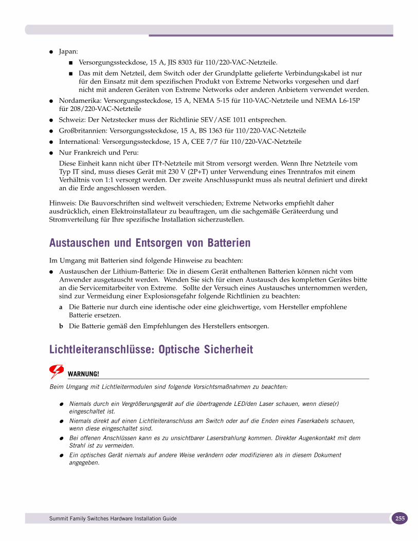
● Japan:
■ Versorgungssteckdose, 15 A, JIS 8303 für 110/220-VAC-Netzteile.
■ Das mit dem Netzteil, dem Switch oder der Grundplatte gelieferte Verbindungskabel ist nur für den Einsatz mit dem spezifischen Produkt von Extreme Networks vorgesehen und darf nicht mit anderen Geräten von Extreme Networks oder anderen Anbietern verwendet werden.
● Nordamerika: Versorgungssteckdose, 15 A, NEMA 5-15 für 110-VAC-Netzteile und NEMA L6-15P für 208/220-VAC-Netzteile
● Schweiz: Der Netzstecker muss der Richtlinie SEV/ASE 1011 entsprechen.
● Großbritannien: Versorgungssteckdose, 15 A, BS 1363 für 110/220-VAC-Netzteile
● International: Versorgungssteckdose, 15 A, CEE 7/7 für 110/220-VAC-Netzteile
● Nur Frankreich und Peru:
Diese Einheit kann nicht über IT†-Netzteile mit Strom versorgt werden. Wenn Ihre Netzteile vom Typ IT sind, muss dieses Gerät mit 230 V (2P+T) unter Verwendung eines Trenntrafos mit einem Verhältnis von 1:1 versorgt werden. Der zweite Anschlusspunkt muss als neutral definiert und direkt an die Erde angeschlossen werden.
Hinweis: Die Bauvorschriften sind weltweit verschieden; Extreme Networks empfiehlt daher ausdrücklich, einen Elektroinstallateur zu beauftragen, um die sachgemäße Geräteerdung und Stromverteilung für Ihre spezifische Installation sicherzustellen.
Austauschen und Entsorgen von BatterienIm Umgang mit Batterien sind folgende Hinweise zu beachten:
● Austauschen der Lithium-Batterie: Die in diesem Gerät enthaltenen Batterien können nicht vom Anwender ausgetauscht werden. Wenden Sie sich für einen Austausch des kompletten Gerätes bitte an die Servicemitarbeiter von Extreme. Sollte der Versuch eines Austausches unternommen werden, sind zur Vermeidung einer Explosionsgefahr folgende Richtlinien zu beachten:
a Die Batterie nur durch eine identische oder eine gleichwertige, vom Hersteller empfohlene Batterie ersetzen.
b Die Batterie gemäß den Empfehlungen des Herstellers entsorgen.
Lichtleiteranschlüsse: Optische Sicherheit
WARNUNG!
Beim Umgang mit Lichtleitermodulen sind folgende Vorsichtsmaßnahmen zu beachten:
● Niemals durch ein Vergrößerungsgerät auf die übertragende LED/den Laser schauen, wenn diese(r) eingeschaltet ist.
● Niemals direkt auf einen Lichtleiteranschluss am Switch oder auf die Enden eines Faserkabels schauen, wenn diese eingeschaltet sind.
● Bei offenen Anschlüssen kann es zu unsichtbarer Laserstrahlung kommen. Direkter Augenkontakt mit dem Strahl ist zu vermeiden.
● Ein optisches Gerät niemals auf andere Weise verändern oder modifizieren als in diesem Dokument angegeben.
Summit Family Switches Hardware Installation Guide 255

Safety Information
256
Einhaltung behördlicher Vorschriften durch SFP (Mini-GBIC), XENPAK und XFP● Laserprodukt der Klasse 1
● EN60825-1+A2:2001 oder jünger, Europäische Richtlinie für Lasersysteme
● Anwendung der CE-Kennzeichnung gemäß der Richtlinien 89/336/EWG EMV und 73/23/EWG für Niederspannungsgeräte
Summit Family Switches Hardware Installation Guide
B Technical Specifications
This appendix includes the following specifications for Summit switch series and related components:
● Summit X150 Series Switches on page 257
● Summit X250e Series Switches on page 261
● Summit X350 Series Switches on page 267
● Summit X450 Series Switches on page 270
● Summit X450a Series Switches on page 272
● Summit X450e Series Switches on page 276
● Summit X480 Series Switches on page 279
● Summit X480 Power Supplies on page 283
● Summit X650 Series Switches on page 285
● Summit X650 Power Supplies on page 290
● Summit External Power Supplies on page 291
● Console Connector Pinouts on page 296
NOTE
In this appendix, all references to specific switch model numbers also apply to the equivalent TAA-compliant switch versions.
Summit X150 Series SwitchesThe Summit X150 series includes the following switches:
● Summit X150-24t switch
● Summit X150-24p switch
● Summit X150-48t switch
Table 33: Summit X150 Series Switch Technical Specifications
Physical Dimensions
Summit X150-24t switchSummit X150-24p switch
Height: 1.73 inches (4.4 cm)Width: 17.35 inches (44.1 cm)Depth: 12.13 inches (30.8 cm)
Summit X150-48t switch Height: 1.73 inches (4.4 cm)Width: 17.35 inches (44.1 cm)Depth: 15.28 inches (38.8 cm)
Weight
Summit X150-24t switch 12.01 lb (5.46 kg)
Summit X150-24p switch 14.9 lb (6.8 kg)
Summit X150-48t switch 15.1 lb (6.9 kg)
Summit Family Switches Hardware Installation Guide 257
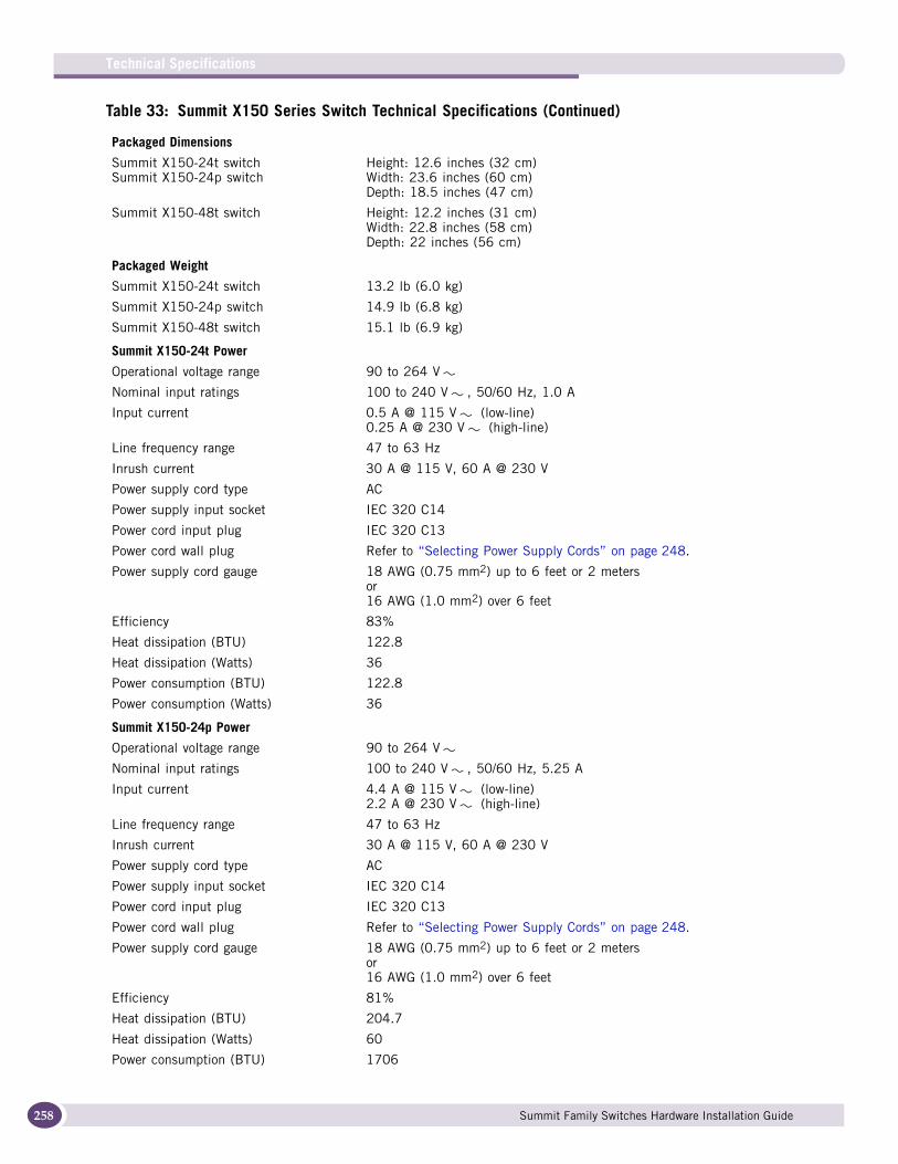
Technical Specifications
258
Packaged Dimensions
Summit X150-24t switchSummit X150-24p switch
Height: 12.6 inches (32 cm)Width: 23.6 inches (60 cm)Depth: 18.5 inches (47 cm)
Summit X150-48t switch Height: 12.2 inches (31 cm)Width: 22.8 inches (58 cm)Depth: 22 inches (56 cm)
Packaged Weight
Summit X150-24t switch 13.2 lb (6.0 kg)
Summit X150-24p switch 14.9 lb (6.8 kg)
Summit X150-48t switch 15.1 lb (6.9 kg)
Summit X150-24t Power
Operational voltage range 90 to 264 V
Nominal input ratings 100 to 240 V , 50/60 Hz, 1.0 A
Input current 0.5 A @ 115 V (low-line)0.25 A @ 230 V (high-line)
Line frequency range 47 to 63 Hz
Inrush current 30 A @ 115 V, 60 A @ 230 V
Power supply cord type AC
Power supply input socket IEC 320 C14
Power cord input plug IEC 320 C13
Power cord wall plug Refer to “Selecting Power Supply Cords” on page 248.
Power supply cord gauge 18 AWG (0.75 mm2) up to 6 feet or 2 metersor16 AWG (1.0 mm2) over 6 feet
Efficiency 83%
Heat dissipation (BTU) 122.8
Heat dissipation (Watts) 36
Power consumption (BTU) 122.8
Power consumption (Watts) 36
Summit X150-24p Power
Operational voltage range 90 to 264 V
Nominal input ratings 100 to 240 V , 50/60 Hz, 5.25 A
Input current 4.4 A @ 115 V (low-line)2.2 A @ 230 V (high-line)
Line frequency range 47 to 63 Hz
Inrush current 30 A @ 115 V, 60 A @ 230 V
Power supply cord type AC
Power supply input socket IEC 320 C14
Power cord input plug IEC 320 C13
Power cord wall plug Refer to “Selecting Power Supply Cords” on page 248.
Power supply cord gauge 18 AWG (0.75 mm2) up to 6 feet or 2 metersor16 AWG (1.0 mm2) over 6 feet
Efficiency 81%
Heat dissipation (BTU) 204.7
Heat dissipation (Watts) 60
Power consumption (BTU) 1706
Table 33: Summit X150 Series Switch Technical Specifications (Continued)
Summit Family Switches Hardware Installation Guide

Power consumption (Watts) 500
Summit X150-48t Power
Operational voltage range 90 to 264 V
Nominal input ratings 100 to 240 V , 50/60 Hz, 1.0 A
Input current 0.6 A @ 115 V (low-line)0.3 A @ 230 V (high-line)
Line frequency range 47 to 63 Hz
Inrush current 30 A @ 115 V, 60 A @ 230 V
Power supply cord type AC
Power supply input socket IEC 320 C14
Power cord input plug IEC 320 C13
Power cord wall plug Refer to “Selecting Power Supply Cords” on page 248.
Power supply cord gauge 18 AWG (0.75 mm2) up to 6 feet or 2 metersor16 AWG (1.0 mm2) over 6 feet
Efficiency 83%
Heat dissipation (BTU) 170.6
Heat dissipation (Watts) 50
Power consumption (BTU) 170.6
Power consumption (Watts) 50
Safety Standards
North American Safety of ITE UL 60950-1:2003 1st Ed., Listed Device (US)CSA 22.2#60950-1-03 1st Ed.(Canada)Complies with FCC 21CFR 1040.10 (US Laser Safety)CDRH Letter of Approval (US FDA Approval)IEEE 802.3af 6-2003 Environment A for PoE Applications
European Safety of ITE EN 60950-1:2001+A11EN 60825-1+A2:2001 (Lasers Safety)TUV-R GS Mark by German Notified Body73/23/EEC Low Voltage Directive
International Safety of ITE CB Report & Certificate per IEC 60950-1:2001 Country Deviations AS/NZX 60950-1 (Australia /New Zealand)
EMI/EMC Standards
North America EMC for ITE FCC CFR 47 part 15 Class A (USA) ICES-003 Class A (Canada)
European EMC standards EN 55022:1998 Class A EN 55024:1998 Class A includes IEC 61000-4-2, 3, 4, 5, 6, 8, 11 EN 61000-3-2,3 (Harmonics & Flicker) ETSI EN 300 386:2001 (EMC Telecommunications)89/336/EEC EMC Directive
International EMC certifications CISPR 22:1997 Class A (International Emissions)CISPR 24:1997 Class A (International Immunity)IEC/EN 61000-4-2 Electrostatic Discharge, 8kV Contact, 15kV Air, Criteria AIEC/EN 61000-4-3 Radiated Immunity 10V/m, Criteria A IEC/EN 61000-4-4 Transient Burst, 1kV, Criteria A IEC/EN 61000-4-5 Surge, 2kV L-L, 2kV L-G, Level 3, Criteria A IEC/EN 61000-4-6 Conducted Immunity, 0.15-80MHz, 10V/m unmod. RMS, Criteria AIEC/EN 61000-4-11 Power Dips & Interruptions, >30%, 25 periods, Criteria C
Table 33: Summit X150 Series Switch Technical Specifications (Continued)
Summit Family Switches Hardware Installation Guide 259

Technical Specifications
260
Country-specific VCCI Class A (Japan Emissions) AS/NZS 3548 ACA (Australia Emissions) CNS 13438:1997 Class A (BSMI-Taiwan) MIC Mark, EMC Approval (Korea)
Telecom StandardsETSI EN 300 386:2001 (EMC Telecommunications) ETSI EN 300 019 (Environmental for Telecommunications)
IEEE 802.3 Media Access Standards IEEE 802.3ab 1000BASE-T
Environmental Data
Environmental Standards EN/ETSI 300 019-2-1 v2.1.2 - Class 1.2 StorageEN/ETSI 300 019-2-2 v2.1.2 - Class 2.3 TransportationEN/ETSI 300 019-2-3 v2.1.2 - Class 3.1e OperationalEN/ETSI 300 753 (1997-10) - Acoustic NoiseASTM D3580 Random Vibration Unpackaged 1.5G
Operating conditions Temperature range: 0° C to 40° C (32° F to 104° F) Humidity: 95% relative humidity, non-condensing Altitude: 0 to 3,000 meters (9,850 feet)Shock (half sine): 30 m/s2 (3 g), 11 ms, 60 shocks Random vibration: 3 to 500 MHz @ 1.5g rms
Storage & transportation conditions (packaged)
Temperature: –40° C to 70° C (–40° F to 158° F) Humidity: 10% to 95% relative humidity, non-condensingPackaged shock (half sine): 180 m/s2 (18 g), 6 ms, 600 shocks Packaged sine vibration: 5 to 62 Hz @ velocity 5 mm/s,
62 to 500 Hz @ 0.2 G Packaged random vibration: 5 to 20 Hz @ 1.0 ASD w/–3 dB/oct.
from 20 to 200 Hz 14 drops minimum on sides & corners @ 42" (<15 kg box)
Acoustic noise (in dBA per ISO 7779) Summit X150-24t:45 (high fan speed)37 (low fan speed)
Summit X150-24p:44 (high fan speed)39 (low fan speed)
Summit X150-48t:47 (high fan speed)37 (low fan speed)
Table 33: Summit X150 Series Switch Technical Specifications (Continued)
Summit Family Switches Hardware Installation Guide
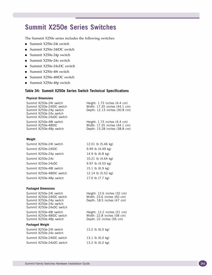
Summit X250e Series SwitchesThe Summit X250e series includes the following switches:
● Summit X250e-24t switch
● Summit X250e-24tDC switch
● Summit X250e-24p switch
● Summit X250e-24x switch
● Summit X250e-24xDC switch
● Summit X250e-48t switch
● Summit X250e-48tDC switch
● Summit X250e-48p switch
Table 34: Summit X250e Series Switch Technical Specifications
Physical Dimensions
Summit X250e-24t switchSummit X250e-24tDC switchSummit X250e-24p switchSummit X250e-24x switchSummit X250e-24xDC switch
Height: 1.73 inches (4.4 cm)Width: 17.35 inches (44.1 cm)Depth: 12.13 inches (30.8 cm)
Summit X250e-48t switch Summit X250e-48tDCSummit X250e-48p switch
Height: 1.73 inches (4.4 cm)Width: 17.35 inches (44.1 cm)Depth: 15.28 inches (38.8 cm)
Weight
Summit X250e-24t switch 12.01 lb (5.46 kg)
Summit X250e-24tDC 9.99 lb (4.49 kg)
Summit X250e-24p switch 14.9 lb (6.8 kg)
Summit X250e-24x 10.21 lb (4.64 kg)
Summit X250e-24xDC 9.97 lb (4.53 kg)
Summit X250e-48t switch 15.1 lb (6.9 kg)
Summit X250e-48tDC switch 12.14 lb (5.52 kg)
Summit X250e-48p switch 17.0 lb (7.7 kg)
Packaged Dimensions
Summit X250e-24t switch Summit X250e-24tDC switchSummit X250e-24p switchSummit X250e-24x switchSummit X250e-24xDC switch
Height: 12.6 inches (32 cm)Width: 23.6 inches (60 cm)Depth: 18.5 inches (47 cm)
Summit X250e-48t switch Summit X250e-48tDC switch Summit X250e-48p switch
Height: 12.2 inches (31 cm)Width: 22.8 inches (58 cm)Depth: 22 inches (56 cm)
Packaged Weight
Summit X250e-24t switch Summit X250e-24x switch
13.2 lb (6.0 kg)
Summit X250e-24tDC switch 13.1 lb (6.0 kg)
Summit X250e-24xDC switch 13.2 lb (6.0 kg)
Summit Family Switches Hardware Installation Guide 261

Technical Specifications
262
Summit X250e-24p switch 14.9 lb (6.8 kg)
Summit X250e-48t switch 15.1 lb (6.9 kg)
Summit X250e-48tDC switch 15.5 lb (7.0 kg)
Summit X250e-48p switch 17.0 lb (7.7 kg)
Summit X250e-24t Power
Operational voltage range 90 to 264 V
Nominal input ratings 100 to 240 V , 50/60 Hz, 1.0 A
Input current 0.5 A @ 115 V (low-line)0.25 A @ 230 V (high-line)
Line frequency range 47 to 63 Hz
Inrush current 30 A @ 115 V, 60 A @ 230 V
Power supply cord type AC
Power supply input socket IEC 320 C14
Power cord input plug IEC 320 C13
Power cord wall plug Refer to “Selecting Power Supply Cords” on page 248.
Power supply cord gauge 18 AWG (0.75 mm2) up to 6 feet or 2 metersor16 AWG (1.0 mm2) over 6 feet
Efficiency 83%
Heat dissipation (Watts) 36
Heat dissipation (BTU/hr)) 122.8
Power consumption (Watts) 36
Power consumption (BTU/hr)) 122.8
Summit X250e-24p Power
Operational voltage range 90 to 264 V
Nominal input ratings 100 to 240 V , 50/60 Hz, 5.25 A
Input current 4.4 A @ 115 V (low-line)2.2 A @ 230 V (high-line)
Line frequency range 47 to 63 Hz
Inrush current 30 A @ 115 V, 60 A @ 230 V
Power supply cord type AC
Power supply input socket IEC 320 C14
Power cord input plug IEC 320 C13
Power cord wall plug Refer to “Selecting Power Supply Cords” on page 248.
Power supply cord gauge 18 AWG (0.75 mm2) up to 6 feet or 2 metersor16 AWG (1.0 mm2) over 6 feet
Efficiency 81%
Heat dissipation (Watts) 60
Heat dissipation (BTU/hrs) 204.7
Power consumption (Watts) 500
Power consumption (BTU/hrs) 1706
Summit X250e-24x Power
Operational voltage range 90 to 264 V
Nominal input ratings 100 to 240 V , 50/60 Hz, 1.0 A
Table 34: Summit X250e Series Switch Technical Specifications (Continued)
Summit Family Switches Hardware Installation Guide

Input current 0.6 A @ 115 V (low-line)0.3 A @ 230 V (high-line)
Line frequency range 47 to 63 Hz
Inrush current 30 A @ 115 V, 60 A @ 230 V
Power supply cord type AC
Power supply input socket IEC 320 C14
Power cord input plug IEC 320 C13
Power cord wall plug Refer to “Selecting Power Supply Cords” on page 248.
Power supply cord gauge 18 AWG (0.75 mm2) up to 6 feet or 2 metersor16 AWG (1.0 mm2) over 6 feet
Efficiency 80%
Heat dissipation (Watts) 46
Heat dissipation (BTU/hr) 157
Power consumption (Watts) 46
Power consumption (BTU/hr) 157
Summit X250e-24xDC Power
Operational voltage range -40 to -57.6 V
Nominal input ratings -48 V , 2.0 A
Input current 1.25 A at -40 V (low-line)0.75 A at -57.6 V (high-line)
Inrush current 20 A at 48 V30 A at 72 V
Power supply cord type DC
Power supply input socket TYCO 206061-1
Power cord input plug TYCO 206060-1
Power cord wall plug None provided
Power supply cord gauge 14 AWG (2.0 mm2)
Efficiency 83%
Heat dissipation (Watts) 42
Heat dissipation (BTU/hr) 143.3
Power consumption (Watts) 42
Power consumption (BTU/hr) 143.3
Summit X250e-24tDC Power
Operational voltage range -40 to -57.6 V
Nominal input ratings -48 V , 2.0 A
Input current 0.8 A at -40 V (low-line)0.5 A at -57.6 V (high-line)
Inrush current 20 A at 48 V, 30 A at 72 V
Power supply cord type DC
Power supply input socket TYCO 206061-1
Power cord input plug TYCO 206060-1
Power cord wall plug None provided
Power supply cord gauge 14 AWG (2.0 mm2)
Table 34: Summit X250e Series Switch Technical Specifications (Continued)
Summit Family Switches Hardware Installation Guide 263
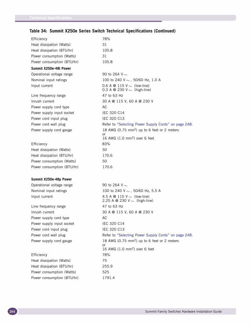
Technical Specifications
264
Efficiency 78%
Heat dissipation (Watts) 31
Heat dissipation (BTU/hr) 105.8
Power consumption (Watts) 31
Power consumption (BTU/hr) 105.8
Summit X250e-48t Power
Operational voltage range 90 to 264 V
Nominal input ratings 100 to 240 V , 50/60 Hz, 1.0 A
Input current 0.6 A @ 115 V (low-line)0.3 A @ 230 V (high-line)
Line frequency range 47 to 63 Hz
Inrush current 30 A @ 115 V, 60 A @ 230 V
Power supply cord type AC
Power supply input socket IEC 320 C14
Power cord input plug IEC 320 C13
Power cord wall plug Refer to “Selecting Power Supply Cords” on page 248.
Power supply cord gauge 18 AWG (0.75 mm2) up to 6 feet or 2 metersor16 AWG (1.0 mm2) over 6 feet
Efficiency 83%
Heat dissipation (Watts) 50
Heat dissipation (BTU/hr) 170.6
Power consumption (Watts) 50
Power consumption (BTU/hr) 170.6
Summit X250e-48p Power
Operational voltage range 90 to 264 V
Nominal input ratings 100 to 240 V , 50/60 Hz, 5.5 A
Input current 4.5 A @ 115 V (low-line)2.25 A @ 230 V (high-line)
Line frequency range 47 to 63 Hz
Inrush current 30 A @ 115 V, 60 A @ 230 V
Power supply cord type AC
Power supply input socket IEC 320 C14
Power cord input plug IEC 320 C13
Power cord wall plug Refer to “Selecting Power Supply Cords” on page 248.
Power supply cord gauge 18 AWG (0.75 mm2) up to 6 feet or 2 metersor16 AWG (1.0 mm2) over 6 feet
Efficiency 78%
Heat dissipation (Watts) 75
Heat dissipation (BTU/hr) 255.9
Power consumption (Watts) 525
Power consumption (BTU/hr) 1791.4
Table 34: Summit X250e Series Switch Technical Specifications (Continued)
Summit Family Switches Hardware Installation Guide
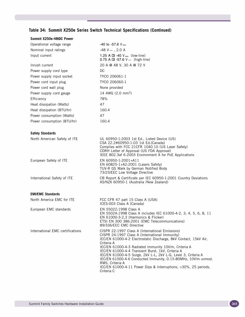
Summit X250e-48tDC Power
Operational voltage range -40 to -57.6 V
Nominal input ratings -48 V , 2.0 A
Input current 1.25 A at -40 V (low-line)0.75 A at -57.6 V (high-line)
Inrush current 20 A @ 48 V, 30 A @ 72 V
Power supply cord type DC
Power supply input socket TYCO 206061-1
Power cord input plug TYCO 206060-1
Power cord wall plug None provided
Power supply cord gauge 14 AWG (2.0 mm2)
Efficiency 78%
Heat dissipation (Watts) 47
Heat dissipation (BTU/hr) 160.4
Power consumption (Watts) 47
Power consumption (BTU/hr) 160.4
Safety Standards
North American Safety of ITE UL 60950-1:2003 1st Ed., Listed Device (US) CSA 22.2#60950-1-03 1st Ed.(Canada) Complies with FCC 21CFR 1040.10 (US Laser Safety) CDRH Letter of Approval (US FDA Approval) IEEE 802.3af 6-2003 Environment A for PoE Applications
European Safety of ITE EN 60950-1:2001+A11 EN 60825-1+A2:2001 (Lasers Safety) TUV-R GS Mark by German Notified Body 73/23/EEC Low Voltage Directive
International Safety of ITE CB Report & Certificate per IEC 60950-1:2001 Country Deviations AS/NZX 60950-1 (Australia /New Zealand)
EMI/EMC Standards
North America EMC for ITE FCC CFR 47 part 15 Class A (USA) ICES-003 Class A (Canada)
European EMC standards EN 55022:1998 Class A EN 55024:1998 Class A includes IEC 61000-4-2, 3, 4, 5, 6, 8, 11EN 61000-3-2,3 (Harmonics & Flicker) ETSI EN 300 386:2001 (EMC Telecommunications) 89/336/EEC EMC Directive
International EMC certifications CISPR 22:1997 Class A (International Emissions) CISPR 24:1997 Class A (International Immunity) IEC/EN 61000-4-2 Electrostatic Discharge, 8kV Contact, 15kV Air, Criteria A IEC/EN 61000-4-3 Radiated Immunity 10V/m, Criteria AIEC/EN 61000-4-4 Transient Burst, 1kV, Criteria AIEC/EN 61000-4-5 Surge, 2kV L-L, 2kV L-G, Level 3, Criteria AIEC/EN 61000-4-6 Conducted Immunity, 0.15-80MHz, 10V/m unmod. RMS, Criteria A IEC/EN 61000-4-11 Power Dips & Interruptions, >30%, 25 periods, Criteria C
Table 34: Summit X250e Series Switch Technical Specifications (Continued)
Summit Family Switches Hardware Installation Guide 265
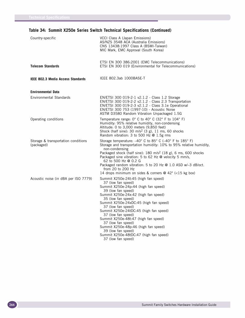
Technical Specifications
266
Country-specific VCCI Class A (Japan Emissions)AS/NZS 3548 ACA (Australia Emissions)CNS 13438:1997 Class A (BSMI-Taiwan)MIC Mark, EMC Approval (South Korea)
Telecom StandardsETSI EN 300 386:2001 (EMC Telecommunications)ETSI EN 300 019 (Environmental for Telecommunications)
IEEE 802.3 Media Access Standards IEEE 802.3ab 1000BASE-T
Environmental Data
Environmental Standards EN/ETSI 300 019-2-1 v2.1.2 - Class 1.2 Storage EN/ETSI 300 019-2-2 v2.1.2 - Class 2.3 Transportation EN/ETSI 300 019-2-3 v2.1.2 - Class 3.1e Operational EN/ETSI 300 753 (1997-10) - Acoustic Noise ASTM D3580 Random Vibration Unpackaged 1.5G
Operating conditions Temperature range: 0° C to 40° C (32° F to 104° F)Humidity: 95% relative humidity, non-condensingAltitude: 0 to 3,000 meters (9,850 feet) Shock (half sine): 30 m/s2 (3 g), 11 ms, 60 shocksRandom vibration: 3 to 500 Hz @ 1.5g rms
Storage & transportation conditions (packaged)
Storage temperature: –40° C to 85° C (–40° F to 185° F)Storage and transportation humidity: 10% to 95% relative humidity,
non-condensing Packaged shock (half sine): 180 m/s2 (18 g), 6 ms, 600 shocksPackaged sine vibration: 5 to 62 Hz @ velocity 5 mm/s,
62 to 500 Hz @ 0.2 GPackaged random vibration: 5 to 20 Hz @ 1.0 ASD w/–3 dB/oct.
from 20 to 200 Hz14 drops minimum on sides & corners @ 42" (<15 kg box)
Acoustic noise (in dBA per ISO 7779) Summit X250e-24t:45 (high fan speed)37 (low fan speed)
Summit X250e-24p:44 (high fan speed)39 (low fan speed)
Summit X250e-24x:42 (high fan speed)35 (low fan speed)
Summit X250e-24xDC:45 (high fan speed)37 (low fan speed)
Summit X250e-24tDC:45 (high fan speed)37 (low fan speed)
Summit X250e-48t:47 (high fan speed)37 (low fan speed)
Summit X250e-48p:46 (high fan speed)39 (low fan speed)
Summit X250e-48tDC:47 (high fan speed)37 (low fan speed)
Table 34: Summit X250e Series Switch Technical Specifications (Continued)
Summit Family Switches Hardware Installation Guide
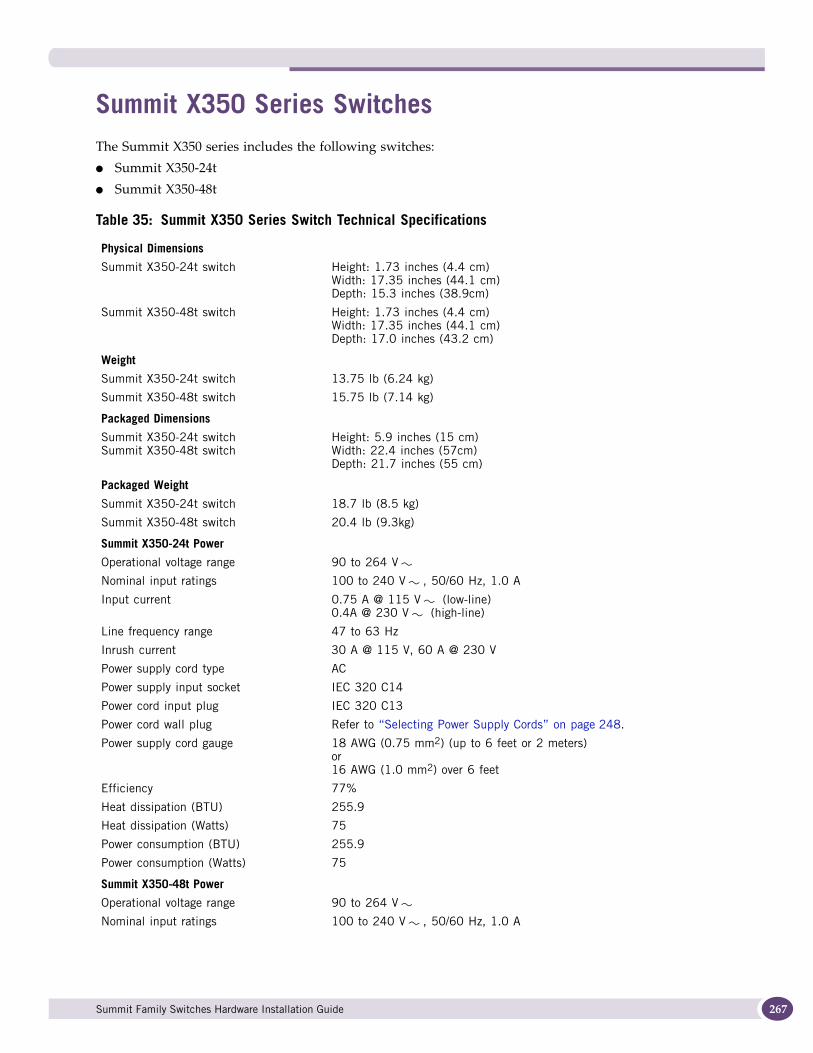
Summit X350 Series SwitchesThe Summit X350 series includes the following switches:
● Summit X350-24t
● Summit X350-48t
Table 35: Summit X350 Series Switch Technical Specifications
Physical Dimensions
Summit X350-24t switch Height: 1.73 inches (4.4 cm)Width: 17.35 inches (44.1 cm)Depth: 15.3 inches (38.9cm)
Summit X350-48t switch Height: 1.73 inches (4.4 cm)Width: 17.35 inches (44.1 cm)Depth: 17.0 inches (43.2 cm)
Weight
Summit X350-24t switch 13.75 lb (6.24 kg)
Summit X350-48t switch 15.75 lb (7.14 kg)
Packaged Dimensions
Summit X350-24t switchSummit X350-48t switch
Height: 5.9 inches (15 cm)Width: 22.4 inches (57cm)Depth: 21.7 inches (55 cm)
Packaged Weight
Summit X350-24t switch 18.7 lb (8.5 kg)
Summit X350-48t switch 20.4 lb (9.3kg)
Summit X350-24t Power
Operational voltage range 90 to 264 V
Nominal input ratings 100 to 240 V , 50/60 Hz, 1.0 A
Input current 0.75 A @ 115 V (low-line)0.4A @ 230 V (high-line)
Line frequency range 47 to 63 Hz
Inrush current 30 A @ 115 V, 60 A @ 230 V
Power supply cord type AC
Power supply input socket IEC 320 C14
Power cord input plug IEC 320 C13
Power cord wall plug Refer to “Selecting Power Supply Cords” on page 248.
Power supply cord gauge 18 AWG (0.75 mm2) (up to 6 feet or 2 meters)or16 AWG (1.0 mm2) over 6 feet
Efficiency 77%
Heat dissipation (BTU) 255.9
Heat dissipation (Watts) 75
Power consumption (BTU) 255.9
Power consumption (Watts) 75
Summit X350-48t Power
Operational voltage range 90 to 264 V
Nominal input ratings 100 to 240 V , 50/60 Hz, 1.0 A
Summit Family Switches Hardware Installation Guide 267
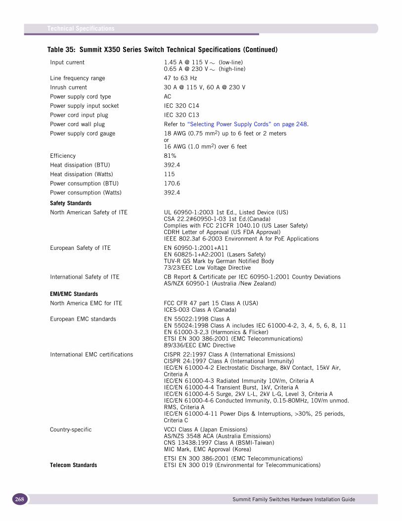
Technical Specifications
268
Input current 1.45 A @ 115 V (low-line)0.65 A @ 230 V (high-line)
Line frequency range 47 to 63 Hz
Inrush current 30 A @ 115 V, 60 A @ 230 V
Power supply cord type AC
Power supply input socket IEC 320 C14
Power cord input plug IEC 320 C13
Power cord wall plug Refer to “Selecting Power Supply Cords” on page 248.
Power supply cord gauge 18 AWG (0.75 mm2) up to 6 feet or 2 metersor16 AWG (1.0 mm2) over 6 feet
Efficiency 81%
Heat dissipation (BTU) 392.4
Heat dissipation (Watts) 115
Power consumption (BTU) 170.6
Power consumption (Watts) 392.4
Safety Standards
North American Safety of ITE UL 60950-1:2003 1st Ed., Listed Device (US)CSA 22.2#60950-1-03 1st Ed.(Canada)Complies with FCC 21CFR 1040.10 (US Laser Safety)CDRH Letter of Approval (US FDA Approval)IEEE 802.3af 6-2003 Environment A for PoE Applications
European Safety of ITE EN 60950-1:2001+A11EN 60825-1+A2:2001 (Lasers Safety)TUV-R GS Mark by German Notified Body73/23/EEC Low Voltage Directive
International Safety of ITE CB Report & Certificate per IEC 60950-1:2001 Country Deviations AS/NZX 60950-1 (Australia /New Zealand)
EMI/EMC Standards
North America EMC for ITE FCC CFR 47 part 15 Class A (USA) ICES-003 Class A (Canada)
European EMC standards EN 55022:1998 Class A EN 55024:1998 Class A includes IEC 61000-4-2, 3, 4, 5, 6, 8, 11 EN 61000-3-2,3 (Harmonics & Flicker) ETSI EN 300 386:2001 (EMC Telecommunications)89/336/EEC EMC Directive
International EMC certifications CISPR 22:1997 Class A (International Emissions)CISPR 24:1997 Class A (International Immunity)IEC/EN 61000-4-2 Electrostatic Discharge, 8kV Contact, 15kV Air, Criteria AIEC/EN 61000-4-3 Radiated Immunity 10V/m, Criteria A IEC/EN 61000-4-4 Transient Burst, 1kV, Criteria A IEC/EN 61000-4-5 Surge, 2kV L-L, 2kV L-G, Level 3, Criteria A IEC/EN 61000-4-6 Conducted Immunity, 0.15-80MHz, 10V/m unmod. RMS, Criteria AIEC/EN 61000-4-11 Power Dips & Interruptions, >30%, 25 periods, Criteria C
Country-specific VCCI Class A (Japan Emissions) AS/NZS 3548 ACA (Australia Emissions) CNS 13438:1997 Class A (BSMI-Taiwan) MIC Mark, EMC Approval (Korea)
Telecom StandardsETSI EN 300 386:2001 (EMC Telecommunications) ETSI EN 300 019 (Environmental for Telecommunications)
Table 35: Summit X350 Series Switch Technical Specifications (Continued)
Summit Family Switches Hardware Installation Guide
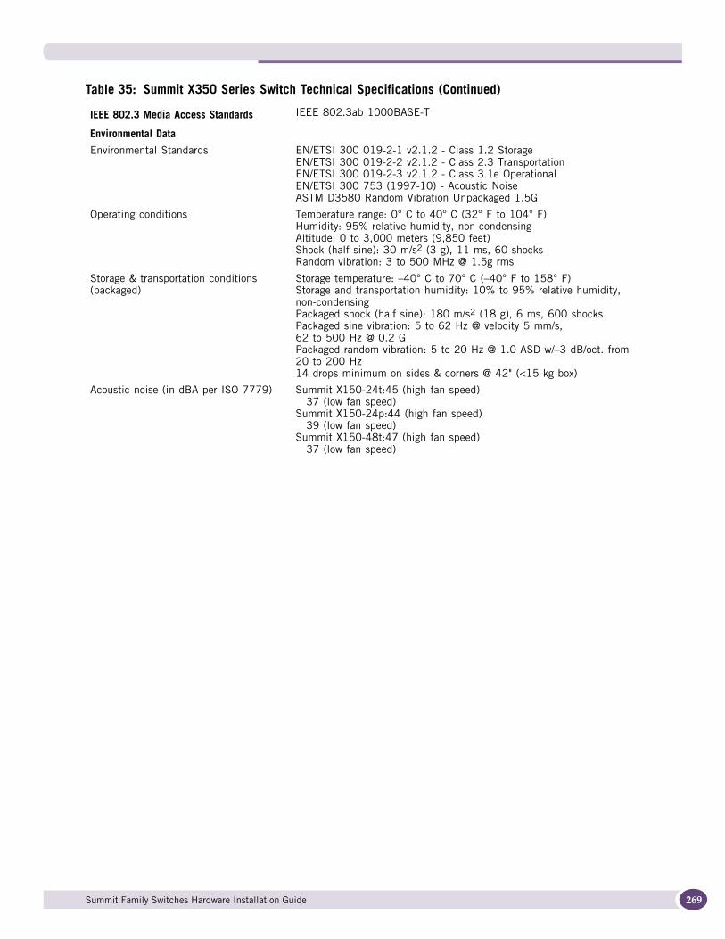
IEEE 802.3 Media Access Standards IEEE 802.3ab 1000BASE-T
Environmental Data
Environmental Standards EN/ETSI 300 019-2-1 v2.1.2 - Class 1.2 StorageEN/ETSI 300 019-2-2 v2.1.2 - Class 2.3 TransportationEN/ETSI 300 019-2-3 v2.1.2 - Class 3.1e OperationalEN/ETSI 300 753 (1997-10) - Acoustic NoiseASTM D3580 Random Vibration Unpackaged 1.5G
Operating conditions Temperature range: 0° C to 40° C (32° F to 104° F) Humidity: 95% relative humidity, non-condensing Altitude: 0 to 3,000 meters (9,850 feet)Shock (half sine): 30 m/s2 (3 g), 11 ms, 60 shocks Random vibration: 3 to 500 MHz @ 1.5g rms
Storage & transportation conditions (packaged)
Storage temperature: –40° C to 70° C (–40° F to 158° F) Storage and transportation humidity: 10% to 95% relative humidity, non-condensingPackaged shock (half sine): 180 m/s2 (18 g), 6 ms, 600 shocks Packaged sine vibration: 5 to 62 Hz @ velocity 5 mm/s,62 to 500 Hz @ 0.2 G Packaged random vibration: 5 to 20 Hz @ 1.0 ASD w/–3 dB/oct. from 20 to 200 Hz 14 drops minimum on sides & corners @ 42" (<15 kg box)
Acoustic noise (in dBA per ISO 7779) Summit X150-24t:45 (high fan speed)37 (low fan speed)
Summit X150-24p:44 (high fan speed)39 (low fan speed)
Summit X150-48t:47 (high fan speed)37 (low fan speed)
Table 35: Summit X350 Series Switch Technical Specifications (Continued)
Summit Family Switches Hardware Installation Guide 269
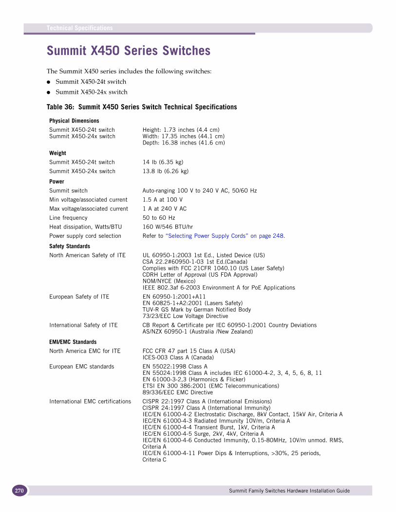
Technical Specifications
270
Summit X450 Series SwitchesThe Summit X450 series includes the following switches:
● Summit X450-24t switch
● Summit X450-24x switch
Table 36: Summit X450 Series Switch Technical Specifications
Physical Dimensions
Summit X450-24t switchSummit X450-24x switch
Height: 1.73 inches (4.4 cm)Width: 17.35 inches (44.1 cm)Depth: 16.38 inches (41.6 cm)
Weight
Summit X450-24t switch 14 lb (6.35 kg)
Summit X450-24x switch 13.8 lb (6.26 kg)
Power
Summit switch Auto-ranging 100 V to 240 V AC, 50/60 Hz
Min voltage/associated current 1.5 A at 100 V
Max voltage/associated current 1 A at 240 V AC
Line frequency 50 to 60 Hz
Heat dissipation, Watts/BTU 160 W/546 BTU/hr
Power supply cord selection Refer to “Selecting Power Supply Cords” on page 248.
Safety Standards
North American Safety of ITE UL 60950-1:2003 1st Ed., Listed Device (US)CSA 22.2#60950-1-03 1st Ed.(Canada)Complies with FCC 21CFR 1040.10 (US Laser Safety)CDRH Letter of Approval (US FDA Approval)NOM/NYCE (Mexico)IEEE 802.3af 6-2003 Environment A for PoE Applications
European Safety of ITE EN 60950-1:2001+A11EN 60825-1+A2:2001 (Lasers Safety)TUV-R GS Mark by German Notified Body73/23/EEC Low Voltage Directive
International Safety of ITE CB Report & Certificate per IEC 60950-1:2001 Country DeviationsAS/NZX 60950-1 (Australia /New Zealand)
EMI/EMC Standards
North America EMC for ITE FCC CFR 47 part 15 Class A (USA)ICES-003 Class A (Canada)
European EMC standards EN 55022:1998 Class AEN 55024:1998 Class A includes IEC 61000-4-2, 3, 4, 5, 6, 8, 11EN 61000-3-2,3 (Harmonics & Flicker)ETSI EN 300 386:2001 (EMC Telecommunications)89/336/EEC EMC Directive
International EMC certifications CISPR 22:1997 Class A (International Emissions)CISPR 24:1997 Class A (International Immunity)IEC/EN 61000-4-2 Electrostatic Discharge, 8kV Contact, 15kV Air, Criteria AIEC/EN 61000-4-3 Radiated Immunity 10V/m, Criteria AIEC/EN 61000-4-4 Transient Burst, 1kV, Criteria AIEC/EN 61000-4-5 Surge, 2kV, 4kV, Criteria AIEC/EN 61000-4-6 Conducted Immunity, 0.15-80MHz, 10V/m unmod. RMS, Criteria AIEC/EN 61000-4-11 Power Dips & Interruptions, >30%, 25 periods, Criteria C
Summit Family Switches Hardware Installation Guide
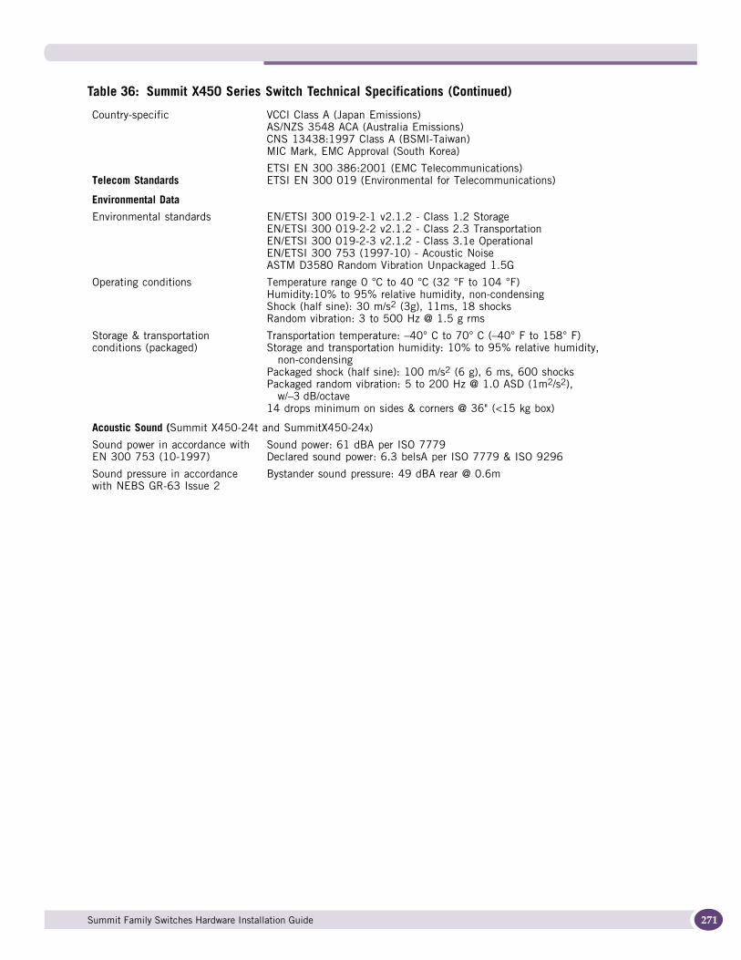
Country-specific VCCI Class A (Japan Emissions)AS/NZS 3548 ACA (Australia Emissions)CNS 13438:1997 Class A (BSMI-Taiwan)MIC Mark, EMC Approval (South Korea)
Telecom StandardsETSI EN 300 386:2001 (EMC Telecommunications)ETSI EN 300 019 (Environmental for Telecommunications)
Environmental Data
Environmental standards EN/ETSI 300 019-2-1 v2.1.2 - Class 1.2 StorageEN/ETSI 300 019-2-2 v2.1.2 - Class 2.3 TransportationEN/ETSI 300 019-2-3 v2.1.2 - Class 3.1e OperationalEN/ETSI 300 753 (1997-10) - Acoustic NoiseASTM D3580 Random Vibration Unpackaged 1.5G
Operating conditions Temperature range 0 °C to 40 °C (32 °F to 104 °F)Humidity:10% to 95% relative humidity, non-condensingShock (half sine): 30 m/s2 (3g), 11ms, 18 shocksRandom vibration: 3 to 500 Hz @ 1.5 g rms
Storage & transportation conditions (packaged)
Transportation temperature: –40° C to 70° C (–40° F to 158° F)Storage and transportation humidity: 10% to 95% relative humidity,
non-condensingPackaged shock (half sine): 100 m/s2 (6 g), 6 ms, 600 shocksPackaged random vibration: 5 to 200 Hz @ 1.0 ASD (1m2/s2),
w/–3 dB/octave14 drops minimum on sides & corners @ 36" (<15 kg box)
Acoustic Sound (Summit X450-24t and SummitX450-24x)
Sound power in accordance with EN 300 753 (10-1997)
Sound power: 61 dBA per ISO 7779 Declared sound power: 6.3 belsA per ISO 7779 & ISO 9296
Sound pressure in accordance with NEBS GR-63 Issue 2
Bystander sound pressure: 49 dBA rear @ 0.6m
Table 36: Summit X450 Series Switch Technical Specifications (Continued)
Summit Family Switches Hardware Installation Guide 271
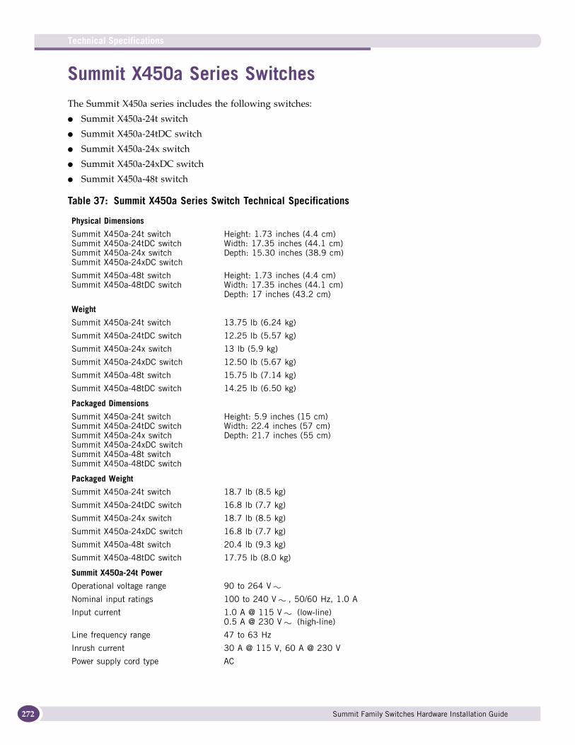
Technical Specifications
272
Summit X450a Series SwitchesThe Summit X450a series includes the following switches:
● Summit X450a-24t switch
● Summit X450a-24tDC switch
● Summit X450a-24x switch
● Summit X450a-24xDC switch
● Summit X450a-48t switch
Table 37: Summit X450a Series Switch Technical Specifications
Physical Dimensions
Summit X450a-24t switchSummit X450a-24tDC switchSummit X450a-24x switchSummit X450a-24xDC switch
Height: 1.73 inches (4.4 cm)Width: 17.35 inches (44.1 cm)Depth: 15.30 inches (38.9 cm)
Summit X450a-48t switchSummit X450a-48tDC switch
Height: 1.73 inches (4.4 cm)Width: 17.35 inches (44.1 cm)Depth: 17 inches (43.2 cm)
Weight
Summit X450a-24t switch 13.75 lb (6.24 kg)
Summit X450a-24tDC switch 12.25 lb (5.57 kg)
Summit X450a-24x switch 13 lb (5.9 kg)
Summit X450a-24xDC switch 12.50 lb (5.67 kg)
Summit X450a-48t switch 15.75 lb (7.14 kg)
Summit X450a-48tDC switch 14.25 lb (6.50 kg)
Packaged Dimensions
Summit X450a-24t switchSummit X450a-24tDC switchSummit X450a-24x switchSummit X450a-24xDC switchSummit X450a-48t switchSummit X450a-48tDC switch
Height: 5.9 inches (15 cm)Width: 22.4 inches (57 cm)Depth: 21.7 inches (55 cm)
Packaged Weight
Summit X450a-24t switch 18.7 lb (8.5 kg)
Summit X450a-24tDC switch 16.8 lb (7.7 kg)
Summit X450a-24x switch 18.7 lb (8.5 kg)
Summit X450a-24xDC switch 16.8 lb (7.7 kg)
Summit X450a-48t switch 20.4 lb (9.3 kg)
Summit X450a-48tDC switch 17.75 lb (8.0 kg)
Summit X450a-24t Power
Operational voltage range 90 to 264 V
Nominal input ratings 100 to 240 V , 50/60 Hz, 1.0 A
Input current 1.0 A @ 115 V (low-line)0.5 A @ 230 V (high-line)
Line frequency range 47 to 63 Hz
Inrush current 30 A @ 115 V, 60 A @ 230 V
Power supply cord type AC
Summit Family Switches Hardware Installation Guide
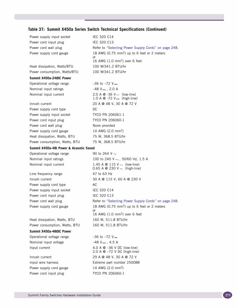
Power supply input socket IEC 320 C14
Power cord input plug IEC 320 C13
Power cord wall plug Refer to “Selecting Power Supply Cords” on page 248.
Power supply cord gauge 18 AWG (0.75 mm2) up to 6 feet or 2 metersor16 AWG (1.0 mm2) over 6 feet
Heat dissipation, Watts/BTU 100 W/341.2 BTU/hr
Power consumption, Watts/BTU 100 W/341.2 BTU/hr
Summit X450a-24tDC Power
Operational voltage range –36 to –72 V
Nominal input ratings –48 V , 2.0 A
Nominal input current 2.0 A @ -36 V (low-line)1.0 A @ -72 V (high-line)
Inrush current 20 A @ 48 V, 30 A @ 72 V
Power supply cord type DC
Power supply input socket TYCO PN 206061-1
Power cord input plug TYCO PN 206060-1
Power cord wall plug None provided
Power supply cord gauge 14 AWG (2.0 mm2)
Heat dissipation, Watts, BTU 75 W, 368.5 BTU/hr
Power consumption, Watts, BTU 75 W, 368.5 BTU/hr
Summit X450a-48t Power & Acoustic Sound
Operational voltage range 90 to 264 V
Nominal input ratings 100 to 240 V , 50/60 Hz, 1.5 A
Nominal input current 1.45 A @ 115 V (low-line)0.65 A @ 230 V (high-line)
Line frequency range 47 to 63 Hz
Inrush current 30 A @ 115 V, 60 A @ 230 V
Power supply cord type AC
Power supply input socket IEC 320 C14
Power cord input plug IEC 320 C13
Power cord wall plug Refer to “Selecting Power Supply Cords” on page 248.
Power supply cord gauge 18 AWG (0.75 mm2) up to 6 feet or 2 metersor16 AWG (1.0 mm2) over 6 feet
Heat dissipation, Watts, BTU 160 W, 511.8 BTU/hr
Power consumption, Watts, BTU 160 W, 511.8 BTU/hr
Summit X450a-48tDC Power
Operational voltage range –36 to –72 V
Nominal input voltage –48 V , 4.5 A
Input current 4.0 A @ –36 V DC (low-line)2.0 A @ –72 V DC (high-line)
Inrush current 29 A @ 48 V, 30 A @ 72 V
Input wire harness Extreme part number 250088
Power supply cord gauge 14 AWG (2.0 mm2)
Power cord input plug TYCO PN 206060-1
Table 37: Summit X450a Series Switch Technical Specifications (Continued)
Summit Family Switches Hardware Installation Guide 273
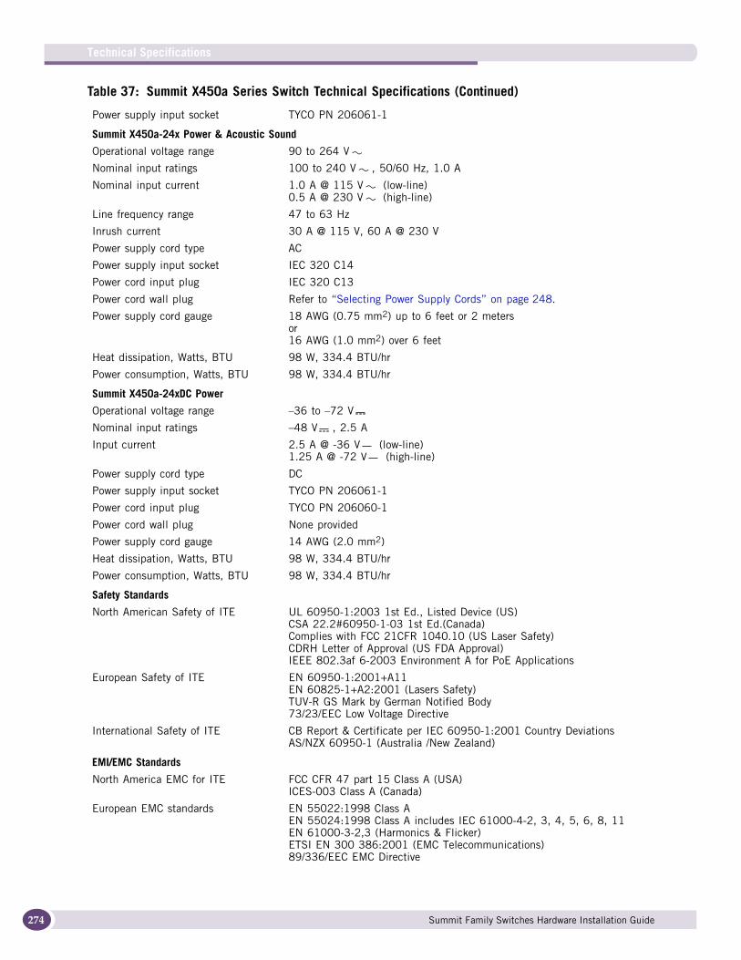
Technical Specifications
274
Power supply input socket TYCO PN 206061-1
Summit X450a-24x Power & Acoustic Sound
Operational voltage range 90 to 264 V
Nominal input ratings 100 to 240 V , 50/60 Hz, 1.0 A
Nominal input current 1.0 A @ 115 V (low-line)0.5 A @ 230 V (high-line)
Line frequency range 47 to 63 Hz
Inrush current 30 A @ 115 V, 60 A @ 230 V
Power supply cord type AC
Power supply input socket IEC 320 C14
Power cord input plug IEC 320 C13
Power cord wall plug Refer to “Selecting Power Supply Cords” on page 248.
Power supply cord gauge 18 AWG (0.75 mm2) up to 6 feet or 2 metersor16 AWG (1.0 mm2) over 6 feet
Heat dissipation, Watts, BTU 98 W, 334.4 BTU/hr
Power consumption, Watts, BTU 98 W, 334.4 BTU/hr
Summit X450a-24xDC Power
Operational voltage range –36 to –72 V
Nominal input ratings –48 V , 2.5 A
Input current 2.5 A @ -36 V (low-line)1.25 A @ -72 V (high-line)
Power supply cord type DC
Power supply input socket TYCO PN 206061-1
Power cord input plug TYCO PN 206060-1
Power cord wall plug None provided
Power supply cord gauge 14 AWG (2.0 mm2)
Heat dissipation, Watts, BTU 98 W, 334.4 BTU/hr
Power consumption, Watts, BTU 98 W, 334.4 BTU/hr
Safety Standards
North American Safety of ITE UL 60950-1:2003 1st Ed., Listed Device (US)CSA 22.2#60950-1-03 1st Ed.(Canada)Complies with FCC 21CFR 1040.10 (US Laser Safety)CDRH Letter of Approval (US FDA Approval)IEEE 802.3af 6-2003 Environment A for PoE Applications
European Safety of ITE EN 60950-1:2001+A11EN 60825-1+A2:2001 (Lasers Safety)TUV-R GS Mark by German Notified Body73/23/EEC Low Voltage Directive
International Safety of ITE CB Report & Certificate per IEC 60950-1:2001 Country DeviationsAS/NZX 60950-1 (Australia /New Zealand)
EMI/EMC Standards
North America EMC for ITE FCC CFR 47 part 15 Class A (USA)ICES-003 Class A (Canada)
European EMC standards EN 55022:1998 Class AEN 55024:1998 Class A includes IEC 61000-4-2, 3, 4, 5, 6, 8, 11EN 61000-3-2,3 (Harmonics & Flicker)ETSI EN 300 386:2001 (EMC Telecommunications)89/336/EEC EMC Directive
Table 37: Summit X450a Series Switch Technical Specifications (Continued)
Summit Family Switches Hardware Installation Guide
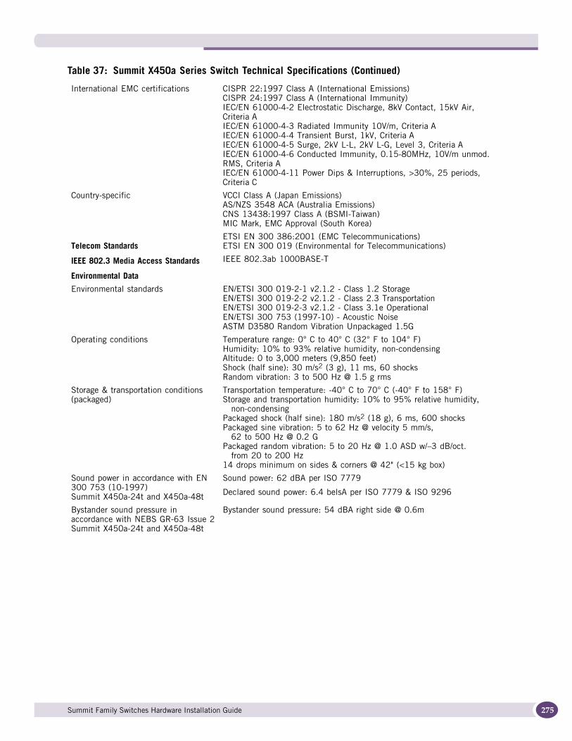
International EMC certifications CISPR 22:1997 Class A (International Emissions)CISPR 24:1997 Class A (International Immunity)IEC/EN 61000-4-2 Electrostatic Discharge, 8kV Contact, 15kV Air, Criteria AIEC/EN 61000-4-3 Radiated Immunity 10V/m, Criteria AIEC/EN 61000-4-4 Transient Burst, 1kV, Criteria AIEC/EN 61000-4-5 Surge, 2kV L-L, 2kV L-G, Level 3, Criteria AIEC/EN 61000-4-6 Conducted Immunity, 0.15-80MHz, 10V/m unmod. RMS, Criteria AIEC/EN 61000-4-11 Power Dips & Interruptions, >30%, 25 periods, Criteria C
Country-specific VCCI Class A (Japan Emissions)AS/NZS 3548 ACA (Australia Emissions)CNS 13438:1997 Class A (BSMI-Taiwan)MIC Mark, EMC Approval (South Korea)
Telecom StandardsETSI EN 300 386:2001 (EMC Telecommunications)ETSI EN 300 019 (Environmental for Telecommunications)
IEEE 802.3 Media Access Standards IEEE 802.3ab 1000BASE-T
Environmental Data
Environmental standards EN/ETSI 300 019-2-1 v2.1.2 - Class 1.2 StorageEN/ETSI 300 019-2-2 v2.1.2 - Class 2.3 TransportationEN/ETSI 300 019-2-3 v2.1.2 - Class 3.1e OperationalEN/ETSI 300 753 (1997-10) - Acoustic NoiseASTM D3580 Random Vibration Unpackaged 1.5G
Operating conditions Temperature range: 0° C to 40° C (32° F to 104° F)Humidity: 10% to 93% relative humidity, non-condensingAltitude: 0 to 3,000 meters (9,850 feet)Shock (half sine): 30 m/s2 (3 g), 11 ms, 60 shocksRandom vibration: 3 to 500 Hz @ 1.5 g rms
Storage & transportation conditions (packaged)
Transportation temperature: -40° C to 70° C (-40° F to 158° F)Storage and transportation humidity: 10% to 95% relative humidity,
non-condensingPackaged shock (half sine): 180 m/s2 (18 g), 6 ms, 600 shocksPackaged sine vibration: 5 to 62 Hz @ velocity 5 mm/s,
62 to 500 Hz @ 0.2 GPackaged random vibration: 5 to 20 Hz @ 1.0 ASD w/–3 dB/oct.
from 20 to 200 Hz14 drops minimum on sides & corners @ 42" (<15 kg box)
Sound power in accordance with EN 300 753 (10-1997)Summit X450a-24t and X450a-48t
Sound power: 62 dBA per ISO 7779
Declared sound power: 6.4 belsA per ISO 7779 & ISO 9296
Bystander sound pressure in accordance with NEBS GR-63 Issue 2Summit X450a-24t and X450a-48t
Bystander sound pressure: 54 dBA right side @ 0.6m
Table 37: Summit X450a Series Switch Technical Specifications (Continued)
Summit Family Switches Hardware Installation Guide 275
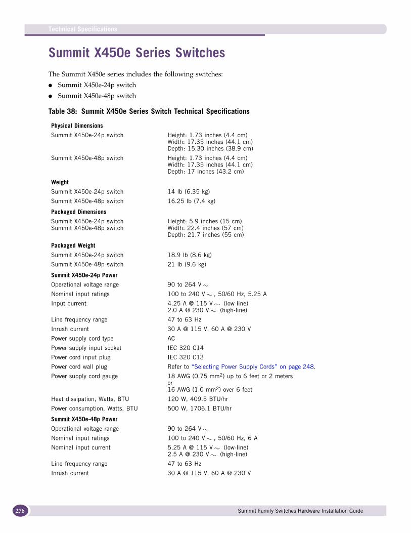
Technical Specifications
276
Summit X450e Series SwitchesThe Summit X450e series includes the following switches:
● Summit X450e-24p switch
● Summit X450e-48p switch
Table 38: Summit X450e Series Switch Technical Specifications
Physical Dimensions
Summit X450e-24p switch Height: 1.73 inches (4.4 cm)Width: 17.35 inches (44.1 cm)Depth: 15.30 inches (38.9 cm)
Summit X450e-48p switch Height: 1.73 inches (4.4 cm)Width: 17.35 inches (44.1 cm)Depth: 17 inches (43.2 cm)
Weight
Summit X450e-24p switch 14 lb (6.35 kg)
Summit X450e-48p switch 16.25 lb (7.4 kg)
Packaged Dimensions
Summit X450e-24p switchSummit X450e-48p switch
Height: 5.9 inches (15 cm)Width: 22.4 inches (57 cm)Depth: 21.7 inches (55 cm)
Packaged Weight
Summit X450e-24p switch 18.9 lb (8.6 kg)
Summit X450e-48p switch 21 lb (9.6 kg)
Summit X450e-24p Power
Operational voltage range 90 to 264 V
Nominal input ratings 100 to 240 V , 50/60 Hz, 5.25 A
Input current 4.25 A @ 115 V (low-line)2.0 A @ 230 V (high-line)
Line frequency range 47 to 63 Hz
Inrush current 30 A @ 115 V, 60 A @ 230 V
Power supply cord type AC
Power supply input socket IEC 320 C14
Power cord input plug IEC 320 C13
Power cord wall plug Refer to “Selecting Power Supply Cords” on page 248.
Power supply cord gauge 18 AWG (0.75 mm2) up to 6 feet or 2 metersor16 AWG (1.0 mm2) over 6 feet
Heat dissipation, Watts, BTU 120 W, 409.5 BTU/hr
Power consumption, Watts, BTU 500 W, 1706.1 BTU/hr
Summit X450e-48p Power
Operational voltage range 90 to 264 V
Nominal input ratings 100 to 240 V , 50/60 Hz, 6 A
Nominal input current 5.25 A @ 115 V (low-line)2.5 A @ 230 V (high-line)
Line frequency range 47 to 63 Hz
Inrush current 30 A @ 115 V, 60 A @ 230 V
Summit Family Switches Hardware Installation Guide

Power supply cord type AC
Power supply input socket IEC 320 C14
Power cord input plug IEC 320 C13
Power cord wall plug Refer to “Selecting Power Supply Cords” on page 248.
Power supply cord gauge 18 AWG (0.75 mm2) up to 6 feet or 2 metersor16 AWG (1.0 mm2) over 6 feet
Heat dissipation, Watts/BTU 180 W/614.2 BTU/hr
Power consumption, Watts/BTU 603 W/2057.5 BTU/hr
Safety Standards
North American Safety of ITE UL 60950-1:2003 1st Ed., Listed Device (US)CSA 22.2#60950-1-03 1st Ed.(Canada)Complies with FCC 21CFR 1040.10 (US Laser Safety)CDRH Letter of Approval (US FDA Approval)IEEE 802.3af 6-2003 Environment A for PoE Applications
European Safety of ITE EN 60950-1:2001+A11EN 60825-1+A2:2001 (Lasers Safety)TUV-R GS Mark by German Notified Body73/23/EEC Low Voltage Directive
International Safety of ITE CB Report & Certificate per IEC 60950-1:2001 Country DeviationsAS/NZX 60950-1 (Australia /New Zealand)
EMI/EMC Standards
North America EMC for ITE FCC CFR 47 part 15 Class A (USA)ICES-003 Class A (Canada)
European EMC standards EN 55022:1998 Class AEN 55024:1998 Class A includes IEC 61000-4-2, 3, 4, 5, 6, 8, 11EN 61000-3-2,3 (Harmonics & Flicker)ETSI EN 300 386:2001 (EMC Telecommunications)89/336/EEC EMC Directive
International EMC certifications CISPR 22:1997 Class A (International Emissions)CISPR 24:1997 Class A (International Immunity)IEC/EN 61000-4-2 Electrostatic Discharge, 8kV Contact, 15kV Air, Criteria AIEC/EN 61000-4-3 Radiated Immunity 10V/m, Criteria AIEC/EN 61000-4-4 Transient Burst, 1kV, Criteria AIEC/EN 61000-4-5 Surge, 2kV L-L, 2kV L-G, Level 3, Criteria AIEC/EN 61000-4-6 Conducted Immunity, 0.15-80MHz, 10V/m unmod. RMS, Criteria AIEC/EN 61000-4-11 Power Dips & Interruptions, >30%, 25 periods, Criteria C
Country-specific VCCI Class A (Japan Emissions)AS/NZS 3548 ACA (Australia Emissions)CNS 13438:1997 Class A (BSMI-Taiwan)MIC Mark, EMC Approval (South Korea)
Telecom StandardsETSI EN 300 386:2001 (EMC Telecommunications)ETSI EN 300 019 (Environmental for Telecommunications)
IEEE 802.3 Media Access Standards IEEE 802.3ab 1000BASE-T
Environmental Data
Environmental standards EN/ETSI 300 019-2-1 v2.1.2 - Class 1.2 StorageEN/ETSI 300 019-2-2 v2.1.2 - Class 2.3 TransportationEN/ETSI 300 019-2-3 v2.1.2 - Class 3.1e OperationalEN/ETSI 300 753 (1997-10) - Acoustic NoiseASTM D3580 Random Vibration Unpackaged 1.5G
Table 38: Summit X450e Series Switch Technical Specifications (Continued)
Summit Family Switches Hardware Installation Guide 277

Technical Specifications
278
Operating conditions Temperature range: 0° C to 40° C (32° F to 104° F)Humidity: 10% to 93% relative humidity, non-condensingAltitude: 0 to 3,000 meters (9,850 feet)Shock (half sine): 30 m/s2 (3 g), 11 ms, 60 shocksRandom vibration: 3 to 500 Hz @ 1.5 g rms
Storage & transportation conditions (packaged)
Transportation temperature: -40° C to 70° C (-40° F to 158° F)Storage and transportation humidity: 10% to 95% relative humidity,
non-condensingPackaged shock (half sine): 180 m/s2 (18 g), 6 ms, 600 shocksPackaged sine vibration: 5 to 62 Hz @ velocity 5 mm/s,
62 to 500 Hz @ 0.2 GPackaged random vibration: 5 to 20 Hz @ 1.0 ASD w/–3 dB/oct.
from 20 to 200 Hz14 drops minimum on sides & corners @ 42"(<15kg box)
Table 38: Summit X450e Series Switch Technical Specifications (Continued)
Summit Family Switches Hardware Installation Guide
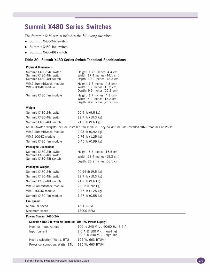
Summit X480 Series SwitchesThe Summit X480 series includes the following switches:
● Summit X480-24x switch
● Summit X480-48x switch
● Summit X480-48t switch
Table 39: Summit X480 Series Switch Technical Specifications
Physical Dimensions
Summit X480-24x switch Summit X480-48x switch Summit X480-48t switch
Height: 1.73 inches (4.4 cm)Width: 17.4 inches (44.1 cm)Depth: 19.0 inches (48.3 cm)
VIM2-SummitStack moduleVIM2-10G4X module
Height: 1.7 inches (4.3 cm)Width: 5.2 inches (13.2 cm)Depth: 9.9 inches (25.2 cm)
Summit X480 fan module Height: 1.7 inches (4.3 cm)Width: 5.2 inches (13.2 cm)Depth: 9.9 inches (25.2 cm)
Weight
Summit X480-24x switch 20.9 lb (9.5 kg)
Summit X480-48x switch 22.7 lb (10.3 kg)
Summit X480-48t switch 21.2 lb (9.6 kg)
NOTE: Switch weights include installed fan module. They do not include installed VIM2 modules or PSUs.
VIM2-SummitStack module 2.03 lb (0.92 kg)
VIM2-10G4X module 2.76 lb (1.25 kg)
Summit X480 fan module 0.45 lb (0.99 kg)
Packaged Dimensions
Summit X480-24x switch Summit X480-48x switch Summit X480-48t switch
Height: 6.5 inches (16.5 cm)
Width: 23.4 inches (59.3 cm)
Depth: 26.2 inches (66.5 cm)
Packaged Weight
Summit X480-24x switch 20.94 lb (9.5 kg)
Summit X480-48x switch 22.7 lb (10.3 kg)
Summit X480-48t switch 21.2 lb (9.6 kg)
VIM2-SummitStack module 2.0 lb (0.92 kg)
VIM2-10G4X module 2.75 lb (1.25 kg)
Summit X480 fan module 1.27 lb (0.58 kg)
Fan Speed
Minimum speed 4500 RPM
Maximum speed 18000 RPM
Power: Summit X480-24x
Summit X480-24x with No Installed VIM (AC Power Supply)
Nominal input ratings 100 to 240 V , 50/60 Hz, 3.5 A
Input current 2.0 A @ 100 V (low-line)0.9 A @ 240 V (high-line)
Heat dissipation, Watts, BTU 195 W, 663 BTU/hr
Power consumption, Watts, BTU 195 W, 663 BTU/hr
Summit Family Switches Hardware Installation Guide 279
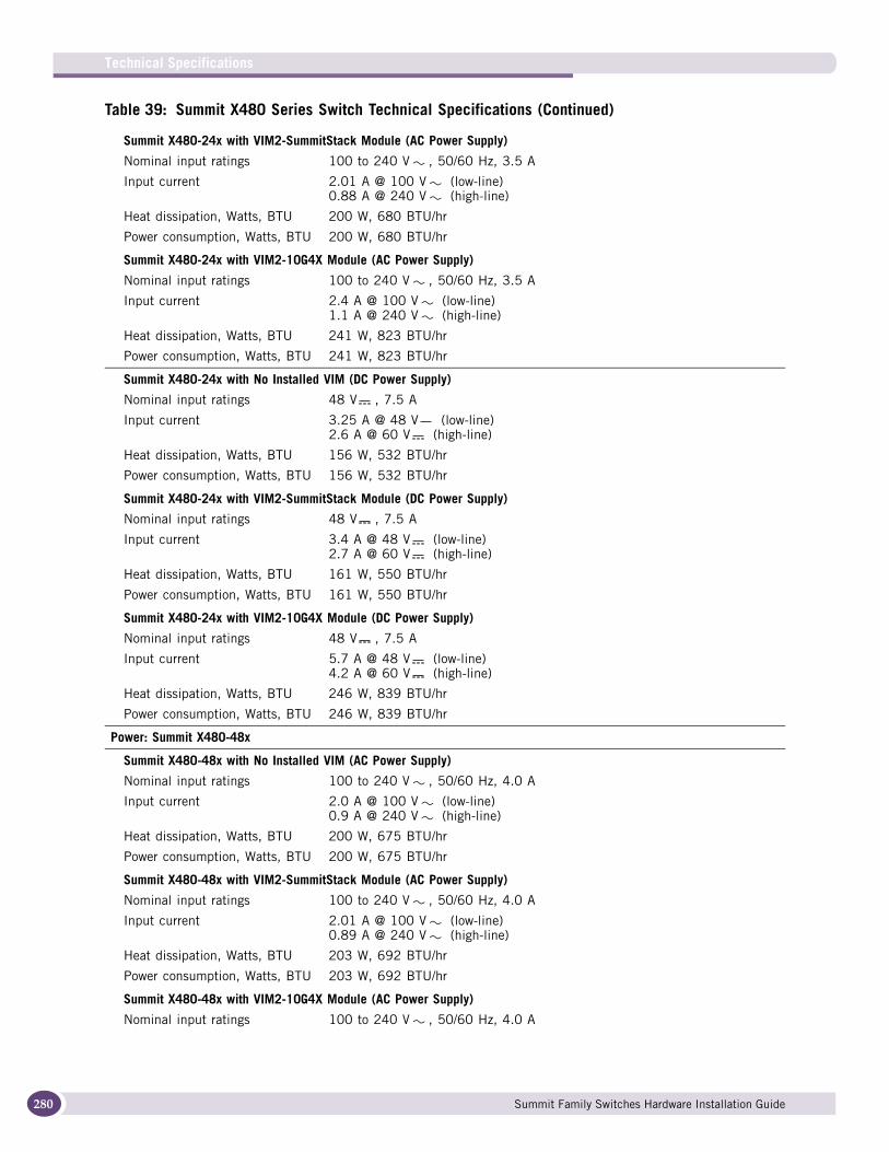
Technical Specifications
280
Summit X480-24x with VIM2-SummitStack Module (AC Power Supply)
Nominal input ratings 100 to 240 V , 50/60 Hz, 3.5 A
Input current 2.01 A @ 100 V (low-line)0.88 A @ 240 V (high-line)
Heat dissipation, Watts, BTU 200 W, 680 BTU/hr
Power consumption, Watts, BTU 200 W, 680 BTU/hr
Summit X480-24x with VIM2-10G4X Module (AC Power Supply)
Nominal input ratings 100 to 240 V , 50/60 Hz, 3.5 A
Input current 2.4 A @ 100 V (low-line)1.1 A @ 240 V (high-line)
Heat dissipation, Watts, BTU 241 W, 823 BTU/hr
Power consumption, Watts, BTU 241 W, 823 BTU/hr
Summit X480-24x with No Installed VIM (DC Power Supply)
Nominal input ratings 48 V , 7.5 A
Input current 3.25 A @ 48 V (low-line)2.6 A @ 60 V (high-line)
Heat dissipation, Watts, BTU 156 W, 532 BTU/hr
Power consumption, Watts, BTU 156 W, 532 BTU/hr
Summit X480-24x with VIM2-SummitStack Module (DC Power Supply)
Nominal input ratings 48 V , 7.5 A
Input current 3.4 A @ 48 V (low-line)2.7 A @ 60 V (high-line)
Heat dissipation, Watts, BTU 161 W, 550 BTU/hr
Power consumption, Watts, BTU 161 W, 550 BTU/hr
Summit X480-24x with VIM2-10G4X Module (DC Power Supply)
Nominal input ratings 48 V , 7.5 A
Input current 5.7 A @ 48 V (low-line)4.2 A @ 60 V (high-line)
Heat dissipation, Watts, BTU 246 W, 839 BTU/hr
Power consumption, Watts, BTU 246 W, 839 BTU/hr
Power: Summit X480-48x
Summit X480-48x with No Installed VIM (AC Power Supply)
Nominal input ratings 100 to 240 V , 50/60 Hz, 4.0 A
Input current 2.0 A @ 100 V (low-line)0.9 A @ 240 V (high-line)
Heat dissipation, Watts, BTU 200 W, 675 BTU/hr
Power consumption, Watts, BTU 200 W, 675 BTU/hr
Summit X480-48x with VIM2-SummitStack Module (AC Power Supply)
Nominal input ratings 100 to 240 V , 50/60 Hz, 4.0 A
Input current 2.01 A @ 100 V (low-line)0.89 A @ 240 V (high-line)
Heat dissipation, Watts, BTU 203 W, 692 BTU/hr
Power consumption, Watts, BTU 203 W, 692 BTU/hr
Summit X480-48x with VIM2-10G4X Module (AC Power Supply)
Nominal input ratings 100 to 240 V , 50/60 Hz, 4.0 A
Table 39: Summit X480 Series Switch Technical Specifications (Continued)
Summit Family Switches Hardware Installation Guide

Input current 2.3 A @ 100 V (low-line)1.0 A @ 240 V (high-line)
Heat dissipation, Watts, BTU 227 W, 774 BTU/hr
Power consumption, Watts, BTU 227 W, 774 BTU/hr
Summit X480-48x with No Installed VIM (DC Power Supply)
Nominal input ratings 48 V , 8.0 A
Input current 3.3 A @ 48 V (low-line)2.6 A @ 60 V (high-line)
Heat dissipation, Watts, BTU 158 W, 540 BTU/hr
Power consumption, Watts, BTU 158 W, 540 BTU/hr
Summit X480-48x with VIM2-SummitStack Module (DC Power Supply)
Nominal input ratings 48 V , 8.0 A
Input current 3.4 A @ 48 V (low-line)2.7 A @ 60 V (high-line)
Heat dissipation, Watts, BTU 163 W, 556 BTU/hr
Power consumption, Watts, BTU 163 W, 556 BTU/hr
Summit X480-48x with VIM2-10G4X Module (DC Power Supply)
Nominal input ratings 48 V , 8.0 A
Input current 5.7 A @ 48 V (low-line)4.4 A @ 60 V (high-line)
Heat dissipation, Watts, BTU 246 W, 839 BTU/hr
Power consumption, Watts, BTU 246 W, 839 BTU/hr
Power: Summit X480-48t
Summit X480-48t with No Installed VIM (AC Power Supply)
Nominal input ratings 100 to 240 V , 50/60 Hz, 3.0 A
Input current 1.9 A @ 100 V (low-line)0.8 A @ 240 V (high-line)
Heat dissipation, Watts, BTU 182 W, 622 BTU/hr
Power consumption, Watts, BTU 182 W, 622 BTU/hr
Summit X480-48t with VIM2-SummitStack Module (AC Power Supply)
Nominal input ratings 100 to 240 V , 50/60 Hz, 3.0 A
Input current 1.89 A @ 100 V (low-line)0.84 A @ 240 V (high-line)
Heat dissipation, Watts, BTU 187 W, 639 BTU/hr
Power consumption, Watts, BTU 187 W, 639 BTU/hr
Summit X480-48t with VIM2-10G4X Module (AC Power Supply)
Nominal input ratings 100 to 240 V , 50/60 Hz, 3.0 A
Input current 2.34 A @ 100 V (low-line)1.0 A @ 240 V (high-line)
Heat dissipation, Watts, BTU 232 W, 793 BTU/hr
Power consumption, Watts, BTU 232 W, 793 BTU/hr
Summit X480-48t with No Installed VIM (DC Power Supply)
Nominal input ratings 48 V , 7.0 A
Input current 3.1 A @ 48 V (low-line)2.4 A @ 60 V (high-line)
Heat dissipation, Watts, BTU 148 W, 503 BTU/hr
Table 39: Summit X480 Series Switch Technical Specifications (Continued)
Summit Family Switches Hardware Installation Guide 281
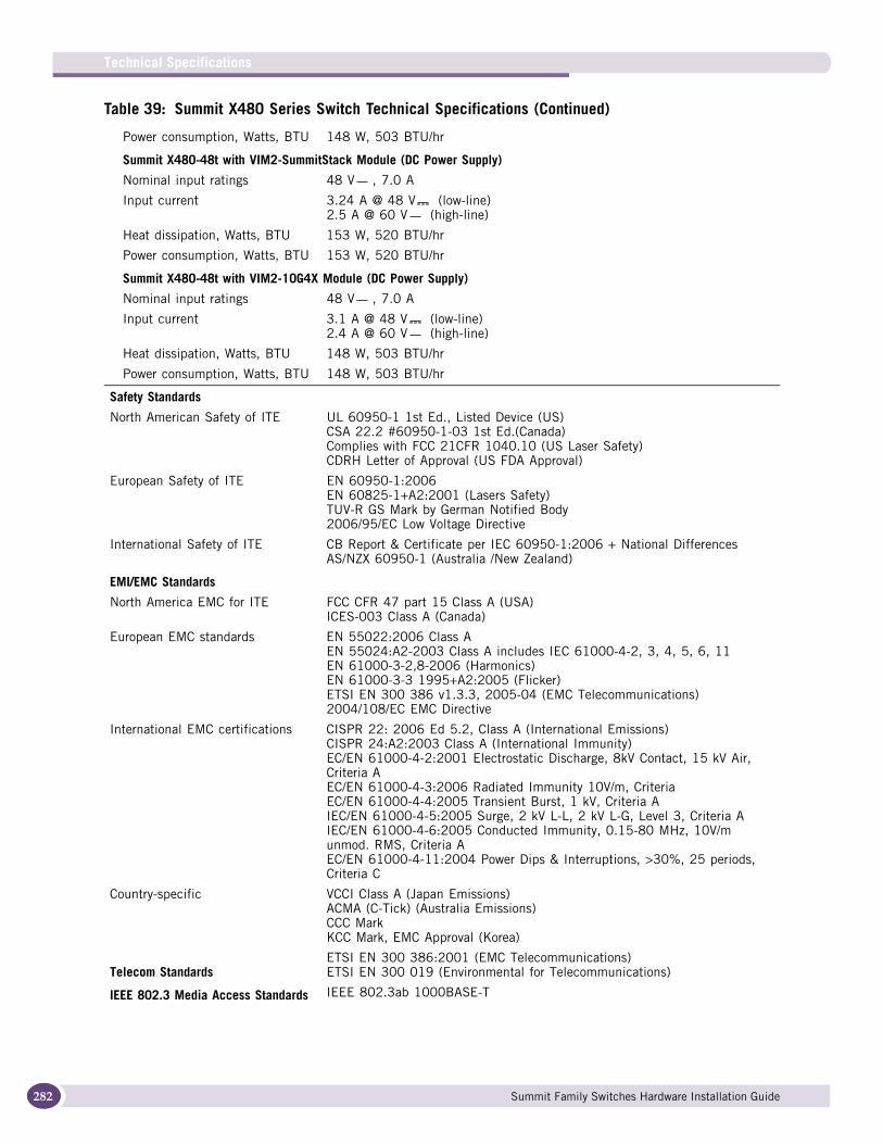
Technical Specifications
282
Power consumption, Watts, BTU 148 W, 503 BTU/hr
Summit X480-48t with VIM2-SummitStack Module (DC Power Supply)
Nominal input ratings 48 V , 7.0 A
Input current 3.24 A @ 48 V (low-line)2.5 A @ 60 V (high-line)
Heat dissipation, Watts, BTU 153 W, 520 BTU/hr
Power consumption, Watts, BTU 153 W, 520 BTU/hr
Summit X480-48t with VIM2-10G4X Module (DC Power Supply)
Nominal input ratings 48 V , 7.0 A
Input current 3.1 A @ 48 V (low-line)2.4 A @ 60 V (high-line)
Heat dissipation, Watts, BTU 148 W, 503 BTU/hr
Power consumption, Watts, BTU 148 W, 503 BTU/hr
Safety Standards
North American Safety of ITE UL 60950-1 1st Ed., Listed Device (US)CSA 22.2 #60950-1-03 1st Ed.(Canada)Complies with FCC 21CFR 1040.10 (US Laser Safety)CDRH Letter of Approval (US FDA Approval)
European Safety of ITE EN 60950-1:2006EN 60825-1+A2:2001 (Lasers Safety)TUV-R GS Mark by German Notified Body2006/95/EC Low Voltage Directive
International Safety of ITE CB Report & Certificate per IEC 60950-1:2006 + National DifferencesAS/NZX 60950-1 (Australia /New Zealand)
EMI/EMC Standards
North America EMC for ITE FCC CFR 47 part 15 Class A (USA)ICES-003 Class A (Canada)
European EMC standards EN 55022:2006 Class AEN 55024:A2-2003 Class A includes IEC 61000-4-2, 3, 4, 5, 6, 11EN 61000-3-2,8-2006 (Harmonics)EN 61000-3-3 1995+A2:2005 (Flicker)ETSI EN 300 386 v1.3.3, 2005-04 (EMC Telecommunications)2004/108/EC EMC Directive
International EMC certifications CISPR 22: 2006 Ed 5.2, Class A (International Emissions)CISPR 24:A2:2003 Class A (International Immunity)EC/EN 61000-4-2:2001 Electrostatic Discharge, 8kV Contact, 15 kV Air, Criteria AEC/EN 61000-4-3:2006 Radiated Immunity 10V/m, Criteria EC/EN 61000-4-4:2005 Transient Burst, 1 kV, Criteria AIEC/EN 61000-4-5:2005 Surge, 2 kV L-L, 2 kV L-G, Level 3, Criteria AIEC/EN 61000-4-6:2005 Conducted Immunity, 0.15-80 MHz, 10V/m unmod. RMS, Criteria AEC/EN 61000-4-11:2004 Power Dips & Interruptions, >30%, 25 periods, Criteria C
Country-specific VCCI Class A (Japan Emissions)ACMA (C-Tick) (Australia Emissions)CCC MarkKCC Mark, EMC Approval (Korea)
Telecom StandardsETSI EN 300 386:2001 (EMC Telecommunications)ETSI EN 300 019 (Environmental for Telecommunications)
IEEE 802.3 Media Access Standards IEEE 802.3ab 1000BASE-T
Table 39: Summit X480 Series Switch Technical Specifications (Continued)
Summit Family Switches Hardware Installation Guide
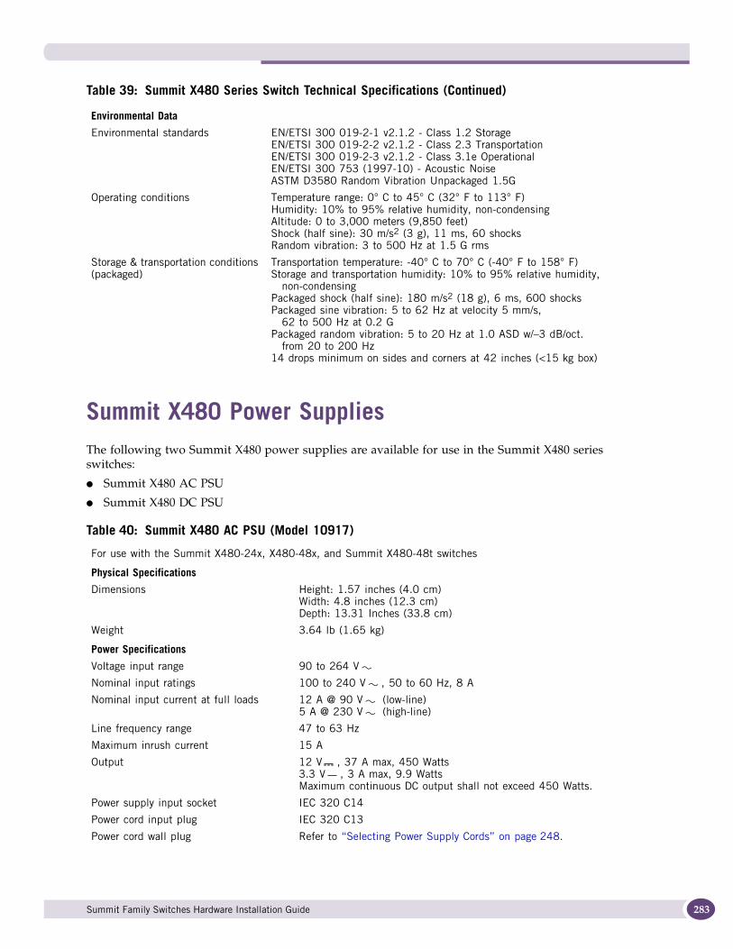
Summit X480 Power SuppliesThe following two Summit X480 power supplies are available for use in the Summit X480 series switches:
● Summit X480 AC PSU
● Summit X480 DC PSU
Environmental Data
Environmental standards EN/ETSI 300 019-2-1 v2.1.2 - Class 1.2 StorageEN/ETSI 300 019-2-2 v2.1.2 - Class 2.3 TransportationEN/ETSI 300 019-2-3 v2.1.2 - Class 3.1e OperationalEN/ETSI 300 753 (1997-10) - Acoustic NoiseASTM D3580 Random Vibration Unpackaged 1.5G
Operating conditions Temperature range: 0° C to 45° C (32° F to 113° F)Humidity: 10% to 95% relative humidity, non-condensingAltitude: 0 to 3,000 meters (9,850 feet)Shock (half sine): 30 m/s2 (3 g), 11 ms, 60 shocksRandom vibration: 3 to 500 Hz at 1.5 G rms
Storage & transportation conditions (packaged)
Transportation temperature: -40° C to 70° C (-40° F to 158° F)Storage and transportation humidity: 10% to 95% relative humidity,
non-condensingPackaged shock (half sine): 180 m/s2 (18 g), 6 ms, 600 shocksPackaged sine vibration: 5 to 62 Hz at velocity 5 mm/s,
62 to 500 Hz at 0.2 GPackaged random vibration: 5 to 20 Hz at 1.0 ASD w/–3 dB/oct.
from 20 to 200 Hz14 drops minimum on sides and corners at 42 inches (<15 kg box)
Table 40: Summit X480 AC PSU (Model 10917)
For use with the Summit X480-24x, X480-48x, and Summit X480-48t switches
Physical Specifications
Dimensions Height: 1.57 inches (4.0 cm)Width: 4.8 inches (12.3 cm)Depth: 13.31 Inches (33.8 cm)
Weight 3.64 lb (1.65 kg)
Power Specifications
Voltage input range 90 to 264 V
Nominal input ratings 100 to 240 V , 50 to 60 Hz, 8 A
Nominal input current at full loads 12 A @ 90 V (low-line)5 A @ 230 V (high-line)
Line frequency range 47 to 63 Hz
Maximum inrush current 15 A
Output 12 V , 37 A max, 450 Watts3.3 V , 3 A max, 9.9 WattsMaximum continuous DC output shall not exceed 450 Watts.
Power supply input socket IEC 320 C14
Power cord input plug IEC 320 C13
Power cord wall plug Refer to “Selecting Power Supply Cords” on page 248.
Table 39: Summit X480 Series Switch Technical Specifications (Continued)
Summit Family Switches Hardware Installation Guide 283
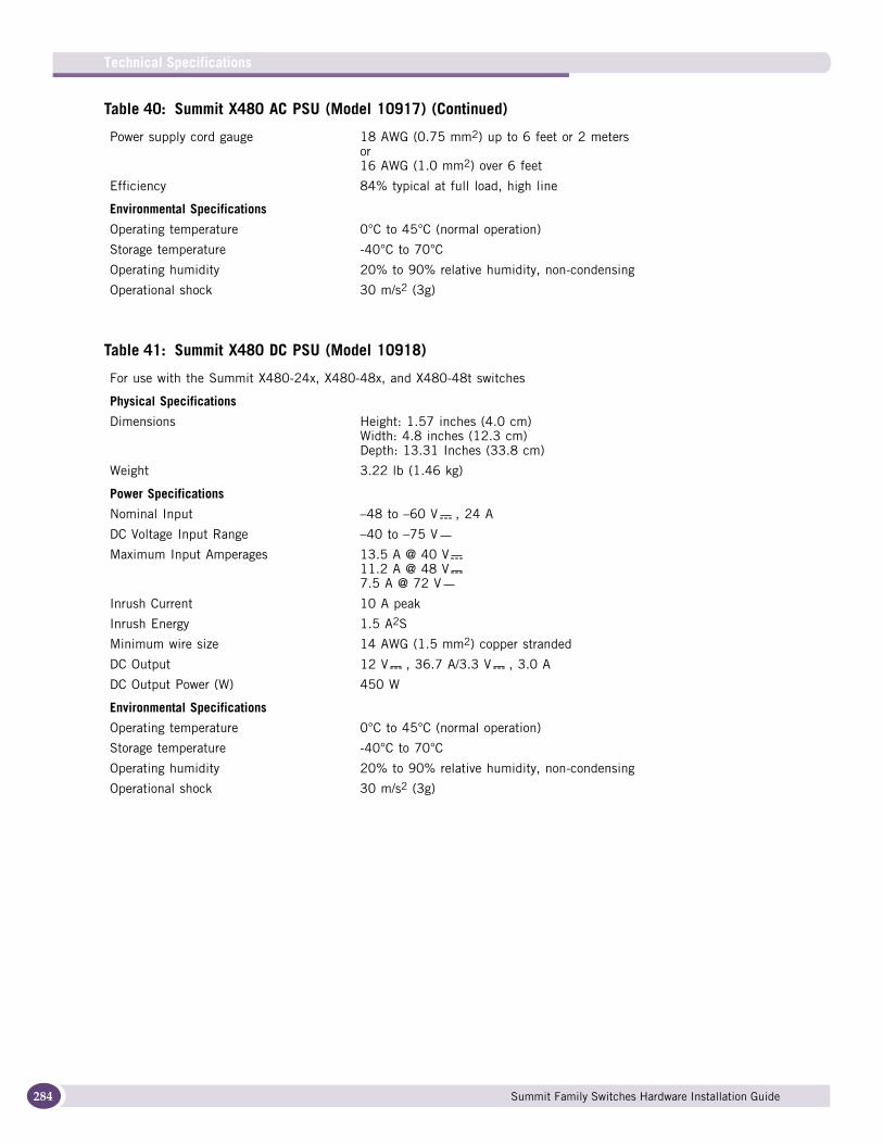
Technical Specifications
284
Power supply cord gauge 18 AWG (0.75 mm2) up to 6 feet or 2 metersor16 AWG (1.0 mm2) over 6 feet
Efficiency 84% typical at full load, high line
Environmental Specifications
Operating temperature 0°C to 45°C (normal operation)
Storage temperature -40°C to 70°C
Operating humidity 20% to 90% relative humidity, non-condensing
Operational shock 30 m/s2 (3g)
Table 41: Summit X480 DC PSU (Model 10918)
For use with the Summit X480-24x, X480-48x, and X480-48t switches
Physical Specifications
Dimensions Height: 1.57 inches (4.0 cm)Width: 4.8 inches (12.3 cm)Depth: 13.31 Inches (33.8 cm)
Weight 3.22 lb (1.46 kg)
Power Specifications
Nominal Input –48 to –60 V , 24 A
DC Voltage Input Range –40 to –75 V
Maximum Input Amperages 13.5 A @ 40 V11.2 A @ 48 V7.5 A @ 72 V
Inrush Current 10 A peak
Inrush Energy 1.5 A2S
Minimum wire size 14 AWG (1.5 mm2) copper stranded
DC Output 12 V , 36.7 A/3.3 V , 3.0 A
DC Output Power (W) 450 W
Environmental Specifications
Operating temperature 0°C to 45°C (normal operation)
Storage temperature -40°C to 70°C
Operating humidity 20% to 90% relative humidity, non-condensing
Operational shock 30 m/s2 (3g)
Table 40: Summit X480 AC PSU (Model 10917) (Continued)
Summit Family Switches Hardware Installation Guide
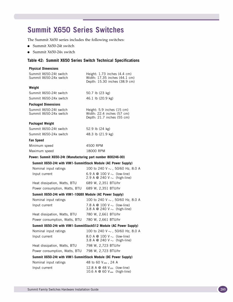
Summit X650 Series SwitchesThe Summit X650 series includes the following switches:
● Summit X650-24t switch
● Summit X650-24x switch
Table 42: Summit X650 Series Switch Technical Specifications
Physical Dimensions
Summit X650-24t switch Summit X650-24x switch
Height: 1.73 inches (4.4 cm)Width: 17.35 inches (44.1 cm)Depth: 15.30 inches (38.9 cm)
Weight
Summit X650-24t switch 50.7 lb (23 kg)
Summit X650-24x switch 46.1 lb (20.9 kg)
Packaged Dimensions
Summit X650-24t switch Summit X650-24x switch
Height: 5.9 inches (15 cm)Width: 22.4 inches (57 cm)Depth: 21.7 inches (55 cm)
Packaged Weight
Summit X650-24t switch 52.9 lb (24 kg)
Summit X650-24x switch 48.3 lb (21.9 kg)
Fan Speed
Minimum speed 4500 RPM
Maximum speed 18000 RPM
Power: Summit X650-24t (Manufacturing part number 800246-00)
Summit X650-24t with VIM1-SummitStack Module (AC Power Supply)
Nominal input ratings 100 to 240 V , 50/60 Hz, 8.0 A
Input current 6.9 A @ 100 V (low-line)2.9 A @ 240 V (high-line)
Heat dissipation, Watts, BTU 689 W, 2,351 BTU/hr
Power consumption, Watts, BTU 689 W, 2,351 BTU/hr
Summit X650-24t with VIM1-10G8X Module (AC Power Supply)
Nominal input ratings 100 to 240 V , 50/60 Hz, 8.0 A
Input current 7.8 A @ 100 V (low-line)3.8 A @ 240 V (high-line)
Heat dissipation, Watts, BTU 780 W, 2,661 BTU/hr
Power consumption, Watts, BTU 780 W, 2,661 BTU/hr
Summit X650-24t with VIM1-SummitStack512 Module (AC Power Supply)
Nominal input ratings 100 to 240 V , 50/60 Hz, 8.0 A
Input current 8.0 A @ 100 V (low-line) 3.8 A @ 240 V (high-line)
Heat dissipation, Watts, BTU 798 W, 2,723 BTU/hr
Power consumption, Watts, BTU 798 W, 2,723 BTU/hr
Summit X650-24t with VIM1-SummitStack Module (DC Power Supply)
Nominal input ratings 48 to 60 V , 24 A
Input current 12.8 A @ 48 V (low-line)10.6 A @ 60 V (high-line)
Summit Family Switches Hardware Installation Guide 285
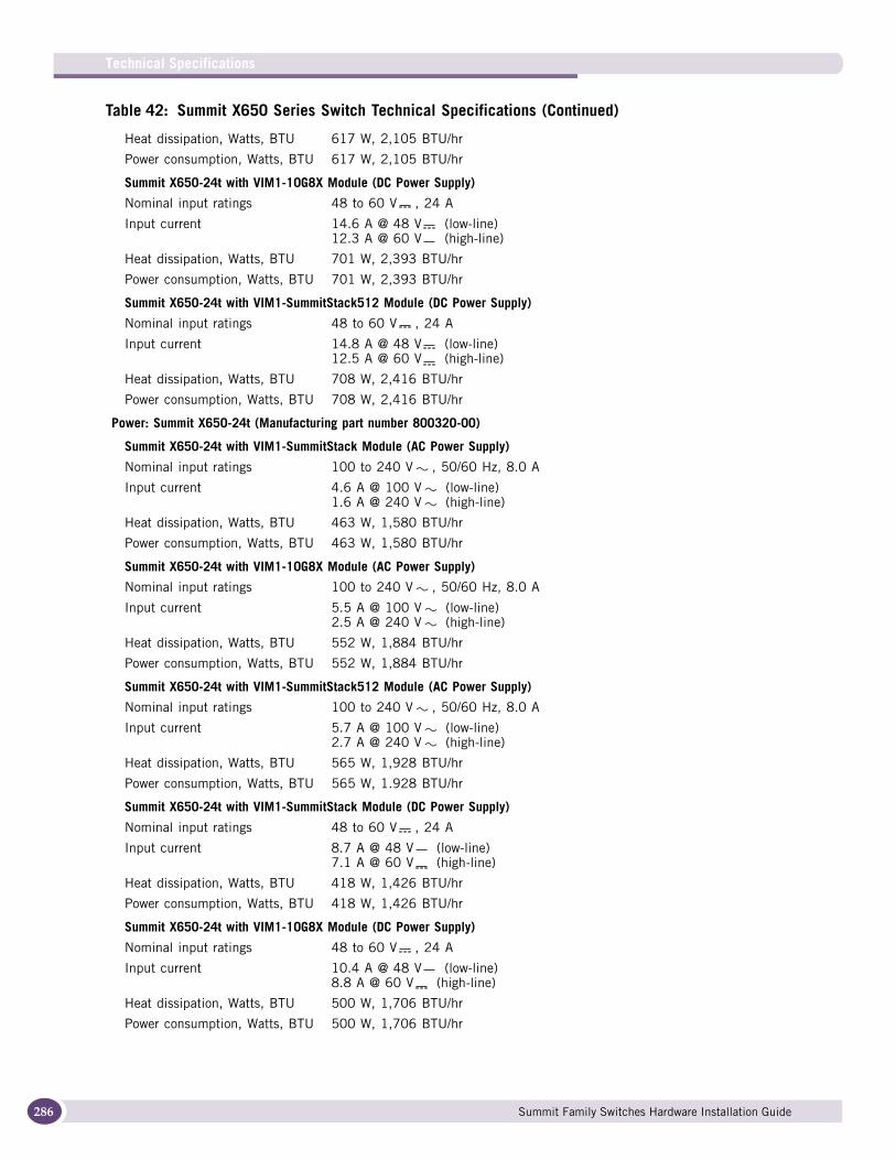
Technical Specifications
286
Heat dissipation, Watts, BTU 617 W, 2,105 BTU/hr
Power consumption, Watts, BTU 617 W, 2,105 BTU/hr
Summit X650-24t with VIM1-10G8X Module (DC Power Supply)
Nominal input ratings 48 to 60 V , 24 A
Input current 14.6 A @ 48 V (low-line)12.3 A @ 60 V (high-line)
Heat dissipation, Watts, BTU 701 W, 2,393 BTU/hr
Power consumption, Watts, BTU 701 W, 2,393 BTU/hr
Summit X650-24t with VIM1-SummitStack512 Module (DC Power Supply)
Nominal input ratings 48 to 60 V , 24 A
Input current 14.8 A @ 48 V (low-line)12.5 A @ 60 V (high-line)
Heat dissipation, Watts, BTU 708 W, 2,416 BTU/hr
Power consumption, Watts, BTU 708 W, 2,416 BTU/hr
Power: Summit X650-24t (Manufacturing part number 800320-00)
Summit X650-24t with VIM1-SummitStack Module (AC Power Supply)
Nominal input ratings 100 to 240 V , 50/60 Hz, 8.0 A
Input current 4.6 A @ 100 V (low-line)1.6 A @ 240 V (high-line)
Heat dissipation, Watts, BTU 463 W, 1,580 BTU/hr
Power consumption, Watts, BTU 463 W, 1,580 BTU/hr
Summit X650-24t with VIM1-10G8X Module (AC Power Supply)
Nominal input ratings 100 to 240 V , 50/60 Hz, 8.0 A
Input current 5.5 A @ 100 V (low-line)2.5 A @ 240 V (high-line)
Heat dissipation, Watts, BTU 552 W, 1,884 BTU/hr
Power consumption, Watts, BTU 552 W, 1,884 BTU/hr
Summit X650-24t with VIM1-SummitStack512 Module (AC Power Supply)
Nominal input ratings 100 to 240 V , 50/60 Hz, 8.0 A
Input current 5.7 A @ 100 V (low-line)2.7 A @ 240 V (high-line)
Heat dissipation, Watts, BTU 565 W, 1,928 BTU/hr
Power consumption, Watts, BTU 565 W, 1.928 BTU/hr
Summit X650-24t with VIM1-SummitStack Module (DC Power Supply)
Nominal input ratings 48 to 60 V , 24 A
Input current 8.7 A @ 48 V (low-line)7.1 A @ 60 V (high-line)
Heat dissipation, Watts, BTU 418 W, 1,426 BTU/hr
Power consumption, Watts, BTU 418 W, 1,426 BTU/hr
Summit X650-24t with VIM1-10G8X Module (DC Power Supply)
Nominal input ratings 48 to 60 V , 24 A
Input current 10.4 A @ 48 V (low-line)8.8 A @ 60 V (high-line)
Heat dissipation, Watts, BTU 500 W, 1,706 BTU/hr
Power consumption, Watts, BTU 500 W, 1,706 BTU/hr
Table 42: Summit X650 Series Switch Technical Specifications (Continued)
Summit Family Switches Hardware Installation Guide
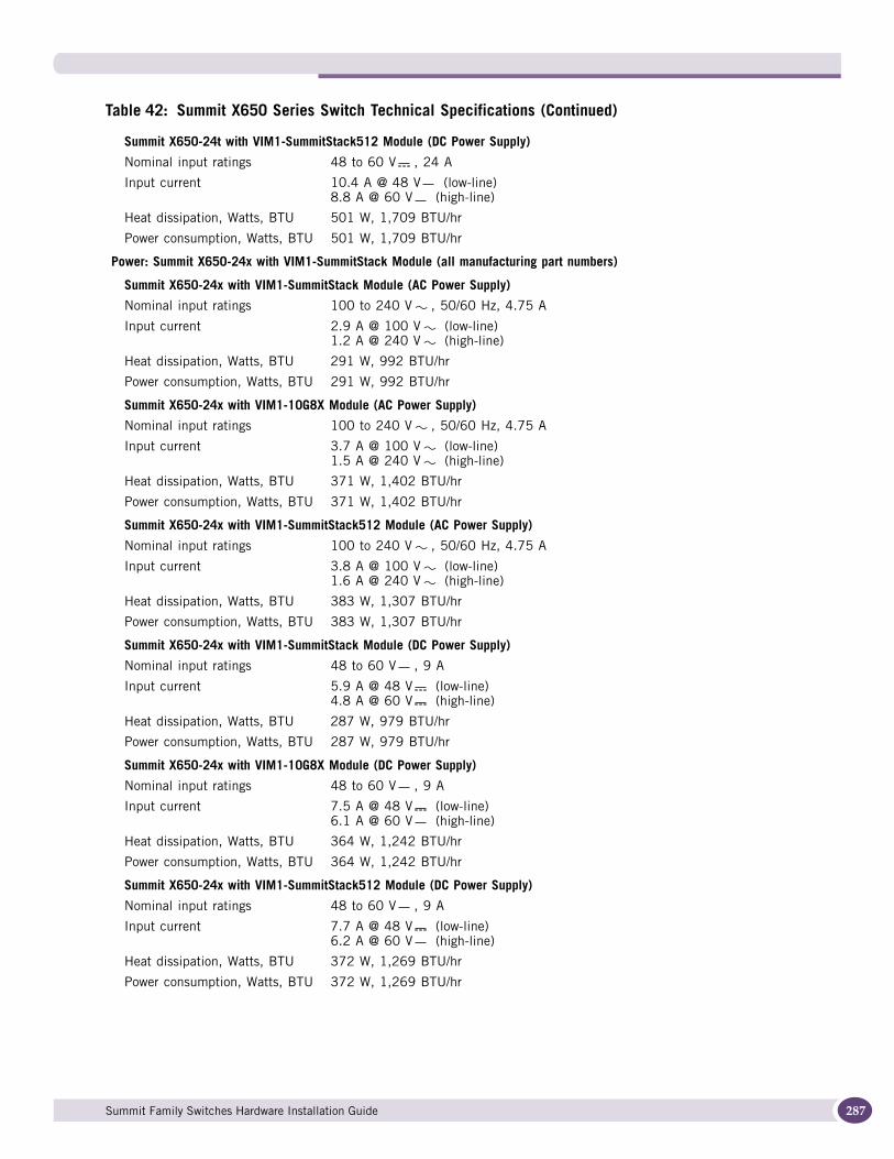
Summit X650-24t with VIM1-SummitStack512 Module (DC Power Supply)
Nominal input ratings 48 to 60 V , 24 A
Input current 10.4 A @ 48 V (low-line)8.8 A @ 60 V (high-line)
Heat dissipation, Watts, BTU 501 W, 1,709 BTU/hr
Power consumption, Watts, BTU 501 W, 1,709 BTU/hr
Power: Summit X650-24x with VIM1-SummitStack Module (all manufacturing part numbers)
Summit X650-24x with VIM1-SummitStack Module (AC Power Supply)
Nominal input ratings 100 to 240 V , 50/60 Hz, 4.75 A
Input current 2.9 A @ 100 V (low-line)1.2 A @ 240 V (high-line)
Heat dissipation, Watts, BTU 291 W, 992 BTU/hr
Power consumption, Watts, BTU 291 W, 992 BTU/hr
Summit X650-24x with VIM1-10G8X Module (AC Power Supply)
Nominal input ratings 100 to 240 V , 50/60 Hz, 4.75 A
Input current 3.7 A @ 100 V (low-line)1.5 A @ 240 V (high-line)
Heat dissipation, Watts, BTU 371 W, 1,402 BTU/hr
Power consumption, Watts, BTU 371 W, 1,402 BTU/hr
Summit X650-24x with VIM1-SummitStack512 Module (AC Power Supply)
Nominal input ratings 100 to 240 V , 50/60 Hz, 4.75 A
Input current 3.8 A @ 100 V (low-line)1.6 A @ 240 V (high-line)
Heat dissipation, Watts, BTU 383 W, 1,307 BTU/hr
Power consumption, Watts, BTU 383 W, 1,307 BTU/hr
Summit X650-24x with VIM1-SummitStack Module (DC Power Supply)
Nominal input ratings 48 to 60 V , 9 A
Input current 5.9 A @ 48 V (low-line)4.8 A @ 60 V (high-line)
Heat dissipation, Watts, BTU 287 W, 979 BTU/hr
Power consumption, Watts, BTU 287 W, 979 BTU/hr
Summit X650-24x with VIM1-10G8X Module (DC Power Supply)
Nominal input ratings 48 to 60 V , 9 A
Input current 7.5 A @ 48 V (low-line)6.1 A @ 60 V (high-line)
Heat dissipation, Watts, BTU 364 W, 1,242 BTU/hr
Power consumption, Watts, BTU 364 W, 1,242 BTU/hr
Summit X650-24x with VIM1-SummitStack512 Module (DC Power Supply)
Nominal input ratings 48 to 60 V , 9 A
Input current 7.7 A @ 48 V (low-line)6.2 A @ 60 V (high-line)
Heat dissipation, Watts, BTU 372 W, 1,269 BTU/hr
Power consumption, Watts, BTU 372 W, 1,269 BTU/hr
Table 42: Summit X650 Series Switch Technical Specifications (Continued)
Summit Family Switches Hardware Installation Guide 287
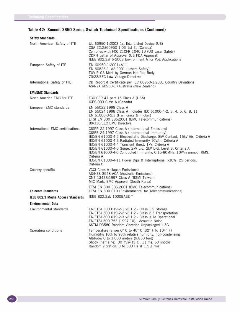
Technical Specifications
288
Safety Standards
North American Safety of ITE UL 60950-1:2003 1st Ed., Listed Device (US)CSA 22.2#60950-1-03 1st Ed.(Canada)Complies with FCC 21CFR 1040.10 (US Laser Safety)CDRH Letter of Approval (US FDA Approval)IEEE 802.3af 6-2003 Environment A for PoE Applications
European Safety of ITE EN 60950-1:2001+A11EN 60825-1+A2:2001 (Lasers Safety)TUV-R GS Mark by German Notified Body73/23/EEC Low Voltage Directive
International Safety of ITE CB Report & Certificate per IEC 60950-1:2001 Country DeviationsAS/NZX 60950-1 (Australia /New Zealand)
EMI/EMC Standards
North America EMC for ITE FCC CFR 47 part 15 Class A (USA)ICES-003 Class A (Canada)
European EMC standards EN 55022:1998 Class AEN 55024:1998 Class A includes IEC 61000-4-2, 3, 4, 5, 6, 8, 11EN 61000-3-2,3 (Harmonics & Flicker)ETSI EN 300 386:2001 (EMC Telecommunications)89/336/EEC EMC Directive
International EMC certifications CISPR 22:1997 Class A (International Emissions)CISPR 24:1997 Class A (International Immunity)IEC/EN 61000-4-2 Electrostatic Discharge, 8kV Contact, 15kV Air, Criteria AIEC/EN 61000-4-3 Radiated Immunity 10V/m, Criteria AIEC/EN 61000-4-4 Transient Burst, 1kV, Criteria AIEC/EN 61000-4-5 Surge, 2kV L-L, 2kV L-G, Level 3, Criteria AIEC/EN 61000-4-6 Conducted Immunity, 0.15-80MHz, 10V/m unmod. RMS, Criteria AIEC/EN 61000-4-11 Power Dips & Interruptions, >30%, 25 periods, Criteria C
Country-specific VCCI Class A (Japan Emissions)AS/NZS 3548 ACA (Australia Emissions)CNS 13438:1997 Class A (BSMI-Taiwan)MIC Mark, EMC Approval (South Korea)
Telecom StandardsETSI EN 300 386:2001 (EMC Telecommunications)ETSI EN 300 019 (Environmental for Telecommunications)
IEEE 802.3 Media Access Standards IEEE 802.3ab 1000BASE-T
Environmental Data
Environmental standards EN/ETSI 300 019-2-1 v2.1.2 - Class 1.2 StorageEN/ETSI 300 019-2-2 v2.1.2 - Class 2.3 TransportationEN/ETSI 300 019-2-3 v2.1.2 - Class 3.1e OperationalEN/ETSI 300 753 (1997-10) - Acoustic NoiseASTM D3580 Random Vibration Unpackaged 1.5G
Operating conditions Temperature range: 0° C to 40° C (32° F to 104° F)Humidity: 10% to 93% relative humidity, non-condensingAltitude: 0 to 3,000 meters (9,850 feet)Shock (half sine): 30 m/s2 (3 g), 11 ms, 60 shocksRandom vibration: 3 to 500 Hz @ 1.5 g rms
Table 42: Summit X650 Series Switch Technical Specifications (Continued)
Summit Family Switches Hardware Installation Guide
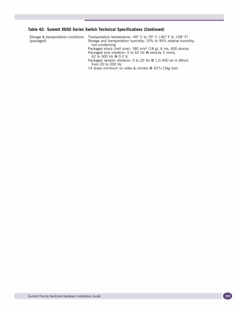
Storage & transportation conditions (packaged)
Transportation temperature: -40° C to 70° C (-40° F to 158° F)Storage and transportation humidity: 10% to 95% relative humidity,
non-condensingPackaged shock (half sine): 180 m/s2 (18 g), 6 ms, 600 shocksPackaged sine vibration: 5 to 62 Hz @ velocity 5 mm/s,
62 to 500 Hz @ 0.2 GPackaged random vibration: 5 to 20 Hz @ 1.0 ASD w/–3 dB/oct.
from 20 to 200 Hz14 drops minimum on sides & corners @ 42"(<15kg box)
Table 42: Summit X650 Series Switch Technical Specifications (Continued)
Summit Family Switches Hardware Installation Guide 289
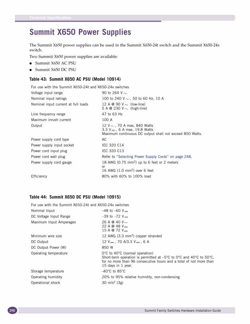
Technical Specifications
290
Summit X650 Power SuppliesThe Summit X650 power supplies can be used in the Summit X650-24t switch and the Summit X650-24x switch.
Two Summit X650 power supplies are available:
● Summit X650 AC PSU
● Summit X650 DC PSU
Table 43: Summit X650 AC PSU (Model 10914)
For use with the Summit X650-24t and X650-24x switches
Voltage input range 90 to 264 V
Nominal input ratings 100 to 240 V , 50 to 60 Hz, 10 A
Nominal input current at full loads 12 A @ 90 V (low-line)5 A @ 230 V (high-line)
Line frequency range 47 to 63 Hz
Maximum inrush current 100 A
Output 12 V , 70 A max, 840 Watts3.3 V , 6 A max, 19.8 WattsMaximum continuous DC output shall not exceed 850 Watts.
Power supply cord type AC
Power supply input socket IEC 320 C14
Power cord input plug IEC 320 C13
Power cord wall plug Refer to “Selecting Power Supply Cords” on page 248.
Power supply cord gauge 18 AWG (0.75 mm2) up to 6 feet or 2 metersor16 AWG (1.0 mm2) over 6 feet
Efficiency 80% with 60% to 100% load
Table 44: Summit X650 DC PSU (Model 10915)
For use with the Summit X650-24t and X650-24x switches
Nominal Input –48 to –60 V
DC Voltage Input Range –39 to –72 V
Maximum Input Amperages 26 A @ 40 V22 A @ 48 V15 A @ 72 V
Minimum wire size 12 AWG (3.3 mm2) copper stranded
DC Output 12 V , 70 A/3.3 V , 6 A
DC Output Power (W) 850 W
Operating temperature 0°C to 40°C (normal operation)Short-term operation is permitted at –5°C to 0°C and 40°C to 50°C, for no more than 96 consecutive hours and a total of not more than 15 days in 1 year.
Storage temperature -40°C to 85°C
Operating humidity 20% to 95% relative humidity, non-condensing
Operational shock 30 m/s2 (3g)
Summit Family Switches Hardware Installation Guide
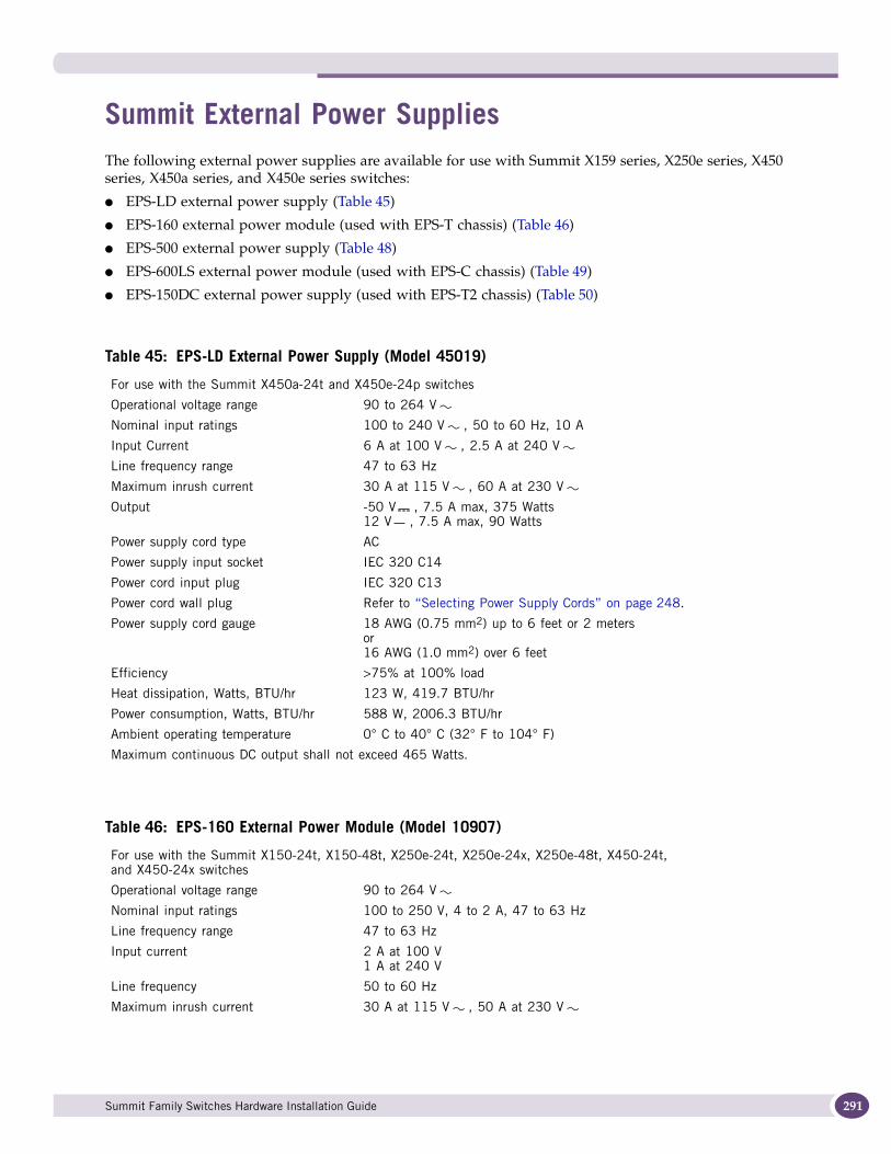
Summit External Power SuppliesThe following external power supplies are available for use with Summit X159 series, X250e series, X450 series, X450a series, and X450e series switches:
● EPS-LD external power supply (Table 45)
● EPS-160 external power module (used with EPS-T chassis) (Table 46)
● EPS-500 external power supply (Table 48)
● EPS-600LS external power module (used with EPS-C chassis) (Table 49)
● EPS-150DC external power supply (used with EPS-T2 chassis) (Table 50)
Table 45: EPS-LD External Power Supply (Model 45019)
For use with the Summit X450a-24t and X450e-24p switches
Operational voltage range 90 to 264 V
Nominal input ratings 100 to 240 V , 50 to 60 Hz, 10 A
Input Current 6 A at 100 V , 2.5 A at 240 V
Line frequency range 47 to 63 Hz
Maximum inrush current 30 A at 115 V , 60 A at 230 V
Output -50 V , 7.5 A max, 375 Watts12 V , 7.5 A max, 90 Watts
Power supply cord type AC
Power supply input socket IEC 320 C14
Power cord input plug IEC 320 C13
Power cord wall plug Refer to “Selecting Power Supply Cords” on page 248.
Power supply cord gauge 18 AWG (0.75 mm2) up to 6 feet or 2 metersor16 AWG (1.0 mm2) over 6 feet
Efficiency >75% at 100% load
Heat dissipation, Watts, BTU/hr 123 W, 419.7 BTU/hr
Power consumption, Watts, BTU/hr 588 W, 2006.3 BTU/hr
Ambient operating temperature 0° C to 40° C (32° F to 104° F)
Maximum continuous DC output shall not exceed 465 Watts.
Table 46: EPS-160 External Power Module (Model 10907)
For use with the Summit X150-24t, X150-48t, X250e-24t, X250e-24x, X250e-48t, X450-24t, and X450-24x switches
Operational voltage range 90 to 264 V
Nominal input ratings 100 to 250 V, 4 to 2 A, 47 to 63 Hz
Line frequency range 47 to 63 Hz
Input current 2 A at 100 V1 A at 240 V
Line frequency 50 to 60 Hz
Maximum inrush current 30 A at 115 V , 50 A at 230 V
Summit Family Switches Hardware Installation Guide 291

Technical Specifications
292
Table 47 shows the wire-to-pin connections for the connector on the rear panel of the EPS-160 power supply.
Output 12 V , 11 A5 V , 1.5 A
Power supply cord type AC
Power supply input socket IEC 320 C14
Power supply input plug IEC 320 C13
Power cord wall plug Refer to “Selecting Power Supply Cords” on page 248.
Power supply cord gauge 18 AWG (0.75 mm2) up to 6 feet or 2 metersor16 AWG (1.0 mm2) over 6 feet
Efficiency 80% at 100% load
Heat dissipation, Watts/BTU 38.5 W, 131.4 BTU/hr
Power consumption, Watts, BTU/hr 178 W, 607.4 BTU/hr
Ambient operating temperature 0° C to 40° C (32° F to 104° F)
Table 47: Pinouts for the Redundant Power Supply Connector
Connector Pin Number Wire Label Pin Number Wire Label
1 NC 8 RS+
2 GND 9 GND
3 GND 10 INT PG
4 GND 11 EXT_CON
5 GND 12 EXT_PG
6 +12 V 13 +5 V
7 +12 V 14 +12 V
Table 48: EPS-500 External Power Supply (Model 109110
For use with the Summit X150-24p, X250e-24p, X450a-24t, X450a-24x, X450a-48t, and X450e-24p switches
Operational voltage range 90 to 264 V
Nominal input ratings 100 to 240 V , 50 to 60 Hz, 10 A
Nominal input current 5.75 A @ 115 V (low-line)2.80 A @ 230 V (high-line)
Line frequency range 47 to 63 Hz
Maximum inrush current 30 A @ 115 V, 60 A @ 220 V
Output -50 V , 7.5 A max, 375 Watts12 V , 10.5 A max, 126 WattsMaximum continuous DC output shall not exceed 500 Watts.
Power supply cord type AC
Power supply input socket IEC 320 C14
Power cord input plug IEC 320 C13
Power cord wall plug Refer to “Selecting Power Supply Cords” on page 248.
Power supply cord gauge 18 AWG (0.75 mm2) up to 6 feet or 2 metersor16 AWG (1.0 mm2) over 6 feet
Efficiency >70% @ 100% load
Table 46: EPS-160 External Power Module (Model 10907) (Continued)
ES4K028
1 7
8 14
Summit Family Switches Hardware Installation Guide

Heat dissipation, Watts, BTU/hr 158 W, 539.1 BTU/hr
Power consumption, Watts, BTU/hr 659 W, 2248.6 BTU/hr
Ambient operating temperature 0° C to 40° C (32° F to 104° F)
Table 48: EPS-500 External Power Supply (Model 109110
Summit Family Switches Hardware Installation Guide 293
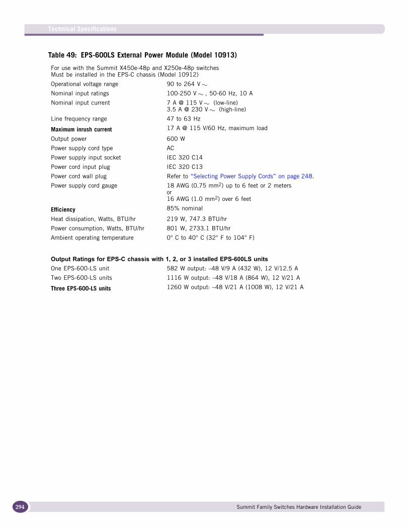
Technical Specifications
294
Table 49: EPS-600LS External Power Module (Model 10913)
For use with the Summit X450e-48p and X250e-48p switchesMust be installed in the EPS-C chassis (Model 10912)
Operational voltage range 90 to 264 V
Nominal input ratings 100-250 V , 50-60 Hz, 10 A
Nominal input current 7 A @ 115 V (low-line)3.5 A @ 230 V (high-line)
Line frequency range 47 to 63 Hz
Maximum inrush current 17 A @ 115 V/60 Hz, maximum load
Output power 600 W
Power supply cord type AC
Power supply input socket IEC 320 C14
Power cord input plug IEC 320 C13
Power cord wall plug Refer to “Selecting Power Supply Cords” on page 248.
Power supply cord gauge 18 AWG (0.75 mm2) up to 6 feet or 2 metersor16 AWG (1.0 mm2) over 6 feet
Efficiency 85% nominal
Heat dissipation, Watts, BTU/hr 219 W, 747.3 BTU/hr
Power consumption, Watts, BTU/hr 801 W, 2733.1 BTU/hr
Ambient operating temperature 0° C to 40° C (32° F to 104° F)
Output Ratings for EPS-C chassis with 1, 2, or 3 installed EPS-600LS units One EPS-600-LS unit 582 W output: –48 V/9 A (432 W), 12 V/12.5 A
Two EPS-600-LS units 1116 W output: –48 V/18 A (864 W), 12 V/21 A
Three EPS-600-LS units 1260 W output: –48 V/21 A (1008 W), 12 V/21 A
Summit Family Switches Hardware Installation Guide
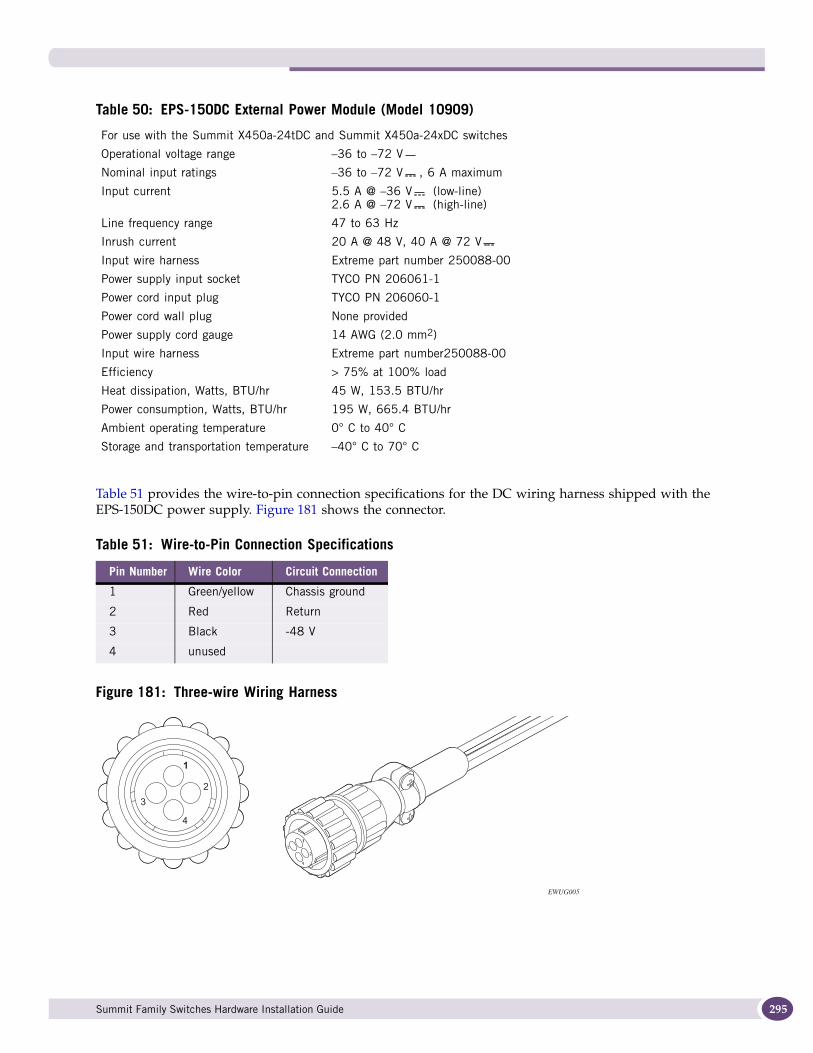
Table 51 provides the wire-to-pin connection specifications for the DC wiring harness shipped with the EPS-150DC power supply. Figure 181 shows the connector.
Figure 181: Three-wire Wiring Harness
Table 50: EPS-150DC External Power Module (Model 10909)
For use with the Summit X450a-24tDC and Summit X450a-24xDC switches
Operational voltage range –36 to –72 V
Nominal input ratings –36 to –72 V , 6 A maximum
Input current 5.5 A @ –36 V (low-line)2.6 A @ –72 V (high-line)
Line frequency range 47 to 63 Hz
Inrush current 20 A @ 48 V, 40 A @ 72 V
Input wire harness Extreme part number 250088-00
Power supply input socket TYCO PN 206061-1
Power cord input plug TYCO PN 206060-1
Power cord wall plug None provided
Power supply cord gauge 14 AWG (2.0 mm2)
Input wire harness Extreme part number250088-00
Efficiency > 75% at 100% load
Heat dissipation, Watts, BTU/hr 45 W, 153.5 BTU/hr
Power consumption, Watts, BTU/hr 195 W, 665.4 BTU/hr
Ambient operating temperature 0° C to 40° C
Storage and transportation temperature –40° C to 70° C
Table 51: Wire-to-Pin Connection Specifications
Pin Number Wire Color Circuit Connection
1 Green/yellow Chassis ground
2 Red Return
3 Black -48 V
4 unused
EWUG005
Summit Family Switches Hardware Installation Guide 295
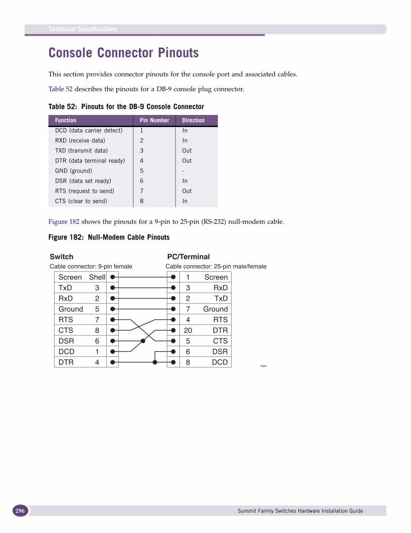
Technical Specifications
296
Console Connector PinoutsThis section provides connector pinouts for the console port and associated cables.
Table 52 describes the pinouts for a DB-9 console plug connector.
Figure 182 shows the pinouts for a 9-pin to 25-pin (RS-232) null-modem cable.
Figure 182: Null-Modem Cable Pinouts
Table 52: Pinouts for the DB-9 Console Connector
Function Pin Number Direction
DCD (data carrier detect) 1 In
RXD (receive data) 2 In
TXD (transmit data) 3 Out
DTR (data terminal ready) 4 Out
GND (ground) 5 -
DSR (data set ready) 6 In
RTS (request to send) 7 Out
CTS (clear to send) 8 In
ScreenTxDRxDGroundRTSCTSDSRDCDDTR
Cable connector: 9-pin female
SwitchCable connector: 25-pin male/female
25pin
PC/Terminal
ScreenRxDTxD
GroundRTSDTRCTSDSRDCD
Shell32578614
13274
20568
Summit Family Switches Hardware Installation Guide
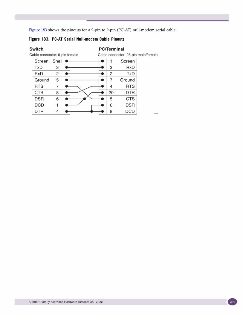
Figure 183 shows the pinouts for a 9-pin to 9-pin (PC-AT) null-modem serial cable.
Figure 183: PC-AT Serial Null-modem Cable Pinouts
ScreenTxDRxDGroundRTSCTSDSRDCDDTR
Cable connector: 9-pin female
SwitchCable connector: 25-pin male/female
25pin
PC/Terminal
ScreenRxDTxD
GroundRTSDTRCTSDSRDCD
Shell32578614
13274
20568
Summit Family Switches Hardware Installation Guide 297

Technical Specifications
298
Summit Family Switches Hardware Installation Guide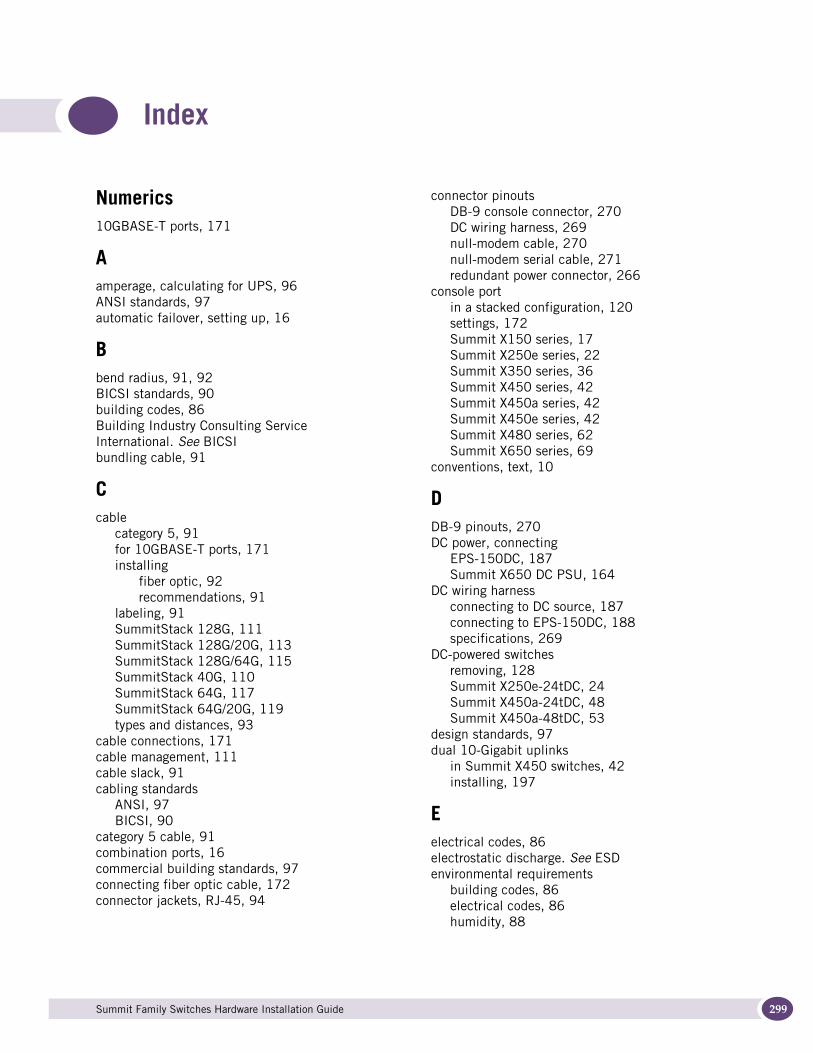
Summit
Index
Numerics10GBASE-T ports, 171
Aamperage, calculating for UPS, 96ANSI standards, 97automatic failover, setting up, 16
Bbend radius, 91, 92BICSI standards, 90building codes, 86Building Industry Consulting Service International. See BICSIbundling cable, 91
Ccable
category 5, 91for 10GBASE-T ports, 171installing
fiber optic, 92recommendations, 91
labeling, 91SummitStack 128G, 111SummitStack 128G/20G, 113SummitStack 128G/64G, 115SummitStack 40G, 110SummitStack 64G, 117SummitStack 64G/20G, 119types and distances, 93
cable connections, 171cable management, 111cable slack, 91cabling standards
ANSI, 97BICSI, 90
category 5 cable, 91combination ports, 16commercial building standards, 97connecting fiber optic cable, 172connector jackets, RJ-45, 94
connector pinoutsDB-9 console connector, 270DC wiring harness, 269null-modem cable, 270null-modem serial cable, 271redundant power connector, 266
console portin a stacked configuration, 120settings, 172Summit X150 series, 17Summit X250e series, 22Summit X350 series, 36Summit X450 series, 42Summit X450a series, 42Summit X450e series, 42Summit X480 series, 62Summit X650 series, 69
conventions, text, 10
DDB-9 pinouts, 270DC power, connecting
EPS-150DC, 187Summit X650 DC PSU, 164
DC wiring harnessconnecting to DC source, 187connecting to EPS-150DC, 188specifications, 269
DC-powered switchesremoving, 128Summit X250e-24tDC, 24Summit X450a-24tDC, 48Summit X450a-48tDC, 53
design standards, 97dual 10-Gigabit uplinks
in Summit X450 switches, 42installing, 197
Eelectrical codes, 86electrostatic discharge. See ESDenvironmental requirements
building codes, 86electrical codes, 86humidity, 88
Family Switches Hardware Installation Guide 299

Index
300
temperature, 87wiring closet, 87
EPS-150DC power supplyfeatures, 78installing, 185specifications, 269with Summit X250e-24tDC switch, 24with Summit X450a-24tDC switch, 48with Summit X450a-24xDC switch, 29, 51with Summit X450a-48tDC switch, 31, 54
EPS-160 power supplyfeatures, 76installing, 176specifications, 265with EPS-T, 77with Summit X450-24t switch, 44with Summit X450-24x switch, 45
EPS-500 power supplyfeatures, 78installing, 182specifications, 266with Summit X350-24t switch, 38with Summit X350a-48t switch, 40with Summit X450a-48t switch, 53with Summit X450e-24p switch, 56
EPS-600LS power supplyfeatures, 79installing, 190specifications, 268with Summit X250e-48p switch, 33with Summit X450e-48p switch, 57
EPS-C chassis (with EPS-600LS), 190EPS-LD power supply
features, 77installing, 179specifications, 265with Summit X450a-24t switch, 47with Summit X450a-24x switch, 50with Summit X450e-24p switch, 56
EPS-T2 (with EPS-150DC), 78, 185equipment rack
grounding, 89mechanical recommendations, 89mounting holes, 89securing, 90service access, 89space requirements, 89
ESDdischarge from cable, 91system protection, 88
FFan LED, Summit X450a series switches, 60
fan specificationsSummit X480 series, 253Summit X650 series, 259
fiber optic cablebend radius, 92connections, 172
first switch login, 173
Ggrounding
DC-powered switch, 125racks, 89requirements, 97Summit X650 DC PSU, 163wiring closet, 87
Hhumidity, 88
Iindustry standards, 97initial switch login, 173installation
10-gigabit uplinks, 197DC-powered switch, 124Summit family switch, 122Summit X480 series switch, 129Summit X650 AC power supply, 159Summit X650 DC power supply, 160Summit X650 series switch, 151Summit XGM2-2xf option card, 200SummitStack configuration, 99
IP settings, configuring, 173
Llabeling system for cables, 91labels, cable, 91LEDs
EPS-150DC power supply, 190EPS-160 power supply, 179, 182EPS-500 power supply, 185stack number indicator, 68, 74stacking port, 120Summit X150 series switches, 21Summit X250e series switches, 35Summit X350 switches, 41Summit X450 switches, 60Summit X480 switches, 68Summit X650 switches, 74
local management connection, 172logging in to the switch, 173
Summit Family Switches Hardware Installation Guide
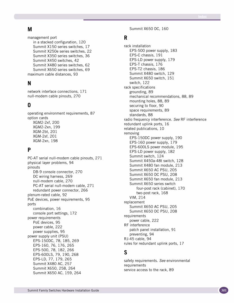
Index
Mmanagement port
in a stacked configuration, 120Summit X150 series switches, 17Summit X250e series switches, 22Summit X350 series switches, 36Summit X450 switches, 42Summit X480 series switches, 62Summit X650 series switches, 69
maximum cable distances, 93
Nnetwork interface connections, 171null-modem cable pinouts, 270
Ooperating environment requirements, 87option cards
XGM2-2xf, 200XGM2-2xn, 199XGM-2bt, 201XGM-2sf, 201XGM-2xn, 198
PPC-AT serial null-modem cable pinouts, 271physical layer problems, 94pinouts
DB-9 console connector, 270DC wiring harness, 269null-modem cable, 270PC-AT serial null-modem cable, 271redundant power connector, 266
plenum-rated cable, 92PoE devices, power requirements, 95ports
combination, 16console port settings, 172
power requirementsPoE devices, 95power cable, 222power supplies, 95
power supply unit (PSU)EPS-150DC, 78, 185, 269EPS-160, 76, 176, 265EPS-500, 78, 182, 266EPS-600LS, 79, 190, 268EPS-LD, 77, 179, 265Summit X480 AC, 257Summit X650, 258, 264Summit X650 AC, 159, 264
Summit X650 DC, 160
Rrack installation
EPS-500 power supply, 183EPS-C chassis, 191EPS-LD power supply, 179EPS-T chassis, 176EPS-T2 chassis, 186Summit X480 switch, 129Summit X650 switch, 151switch, 122
rack specificationsgrounding, 89mechanical recommendations, 88, 89mounting holes, 88, 89securing to floor, 90space requirements, 89standards, 88
radio frequency interference. See RF interferenceredundant uplink ports, 16related publications, 10removing
EPS-150DC power supply, 190EPS-160 power supply, 179EPS-600LS power module, 195EPS-LD power supply, 182Summit switch, 124Summit X450a-48t switch, 128Summit X480 fan module, 213Summit X650 AC PSU, 205Summit X650 DC PSU, 208Summit X650 fan module, 213Summit X650 series switch
four-post rack (cabinet), 170two-post rack, 168
VIM, 214replacement
Summit X650 AC PSU, 205Summit X650 DC PSU, 208
requirementspower cable, 222
RF interferencepatch panel installation, 91preventing, 94
RJ-45 cable, 94rules for redundant uplink ports, 17
Ssafety requirements. See environmental requirementsservice access to the rack, 89
Summit Family Switches Hardware Installation Guide 301
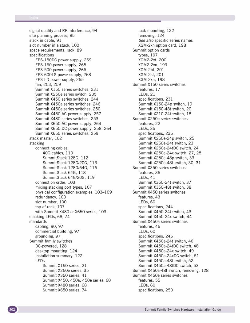
Index
302
signal quality and RF interference, 94site planning process, 85slack in cable, 91slot number in a stack, 100space requirements, rack, 89specifications
EPS-150DC power supply, 269EPS-160 power supply, 265EPS-500 power supply, 266EPS-600LS power supply, 268EPS-LD power supply, 265fan, 253, 259Summit X150 series switches, 231Summit X250e series switch, 235Summit X450 series switches, 244Summit X450a series switches, 246Summit X450e series switches, 250Summit X480 AC power supply, 257Summit X480 series switches, 253Summit X650 AC power supply, 264Summit X650 DC power supply, 258, 264Summit X650 series switches, 259
stack master, 102stacking
connecting cables40G cables, 110SummitStack 128G, 112SummitStack 128G/20G, 113SummitStack 128G/64G, 116SummitStack 64G, 118SummitStack 64G/20G, 119
connection order, 103mixing stacking port types, 107physical configuration examples, 103–109redundancy, 100slot number, 100top-of-rack, 107with Summit X480 or X650 series, 103
stacking LEDs, 68, 74standards
cabling, 90, 97commercial building, 97grounding, 97
Summit family switchesDC-powered, 128desktop mounting, 124installation summary, 122LEDs
Summit X150 series, 21Summit X250e series, 35Summit X350 series, 41Summit X450, 450a, 450e series, 60Summit X480 series, 68Summit X650 series, 74
rack-mounting, 122removing, 124See also specific series namesXGM-2xn option card, 198
Summit option cardstypes, 197XGM2-2xf, 200XGM2-2xn, 199XGM-2bt, 201XGM-2sf, 201XGM-2xn, 198
Summit X150 series switchesfeatures, 17LEDs, 21specifications, 231Summit X150-24p switch, 19Summit X150-48t switch, 20Summit X210-24t switch, 18
Summit X250e series switchesfeatures, 22LEDs, 35specifications, 235Summit X250e-24p switch, 25Summit X250e-24t switch, 23Summit X250e-24tDC switch, 24Summit X250e-24x switch, 27, 28Summit X250e-48p switch, 33Summit X250e-48t switch, 30, 31
Summit X350 series switchesfeatures, 36LEDs, 41Summit X350-24t switch, 37Summit X350-48t switch, 38
Summit X450 series switchesfeatures, 43LEDs, 60specifications, 244Summit X450-24t switch, 43Summit X450-24x switch, 44
Summit X450a series switchesfeatures, 46LEDs, 60specifications, 246Summit X450a-24t switch, 46Summit X450a-24tDC switch, 48Summit X450a-24x switch, 49Summit X450a-24xDC switch, 51Summit X450a-48t switch, 52Summit X450a-48tDC switch, 53
Summit X450a-48t switch, removing, 128Summit X450e series switches
features, 55LEDs, 60specifications, 250
Summit Family Switches Hardware Installation Guide
Index
Summit X450e-24p switch, 55Summit X450e-48p switch, 57
Summit X480 AC power supplyspecifications, 257
Summit X480 power supplyfeatures, 81
Summit X480 series switchesfeatures, 62in a stack, 103LEDs, 68specifications, 253
Summit X650 AC power supplyinstallation, 159specifications, 264
Summit X650 DC power supplyinstallation, 160specifications, 258, 264
Summit X650 power supplyfeatures, 82
Summit X650 series switchesfeatures, 69in a stack, 103LEDs, 74specifications, 259Summit X650 24t switch, 70Summit X650-24x switch, 71
Summit XGM2-2bt option card, 201Summit XGM2-2sf option card, 201Summit XGM2-2xf option card, 200Summit XGM2-2xn option card, 199Summit XGM-2xn option card, 198SummitStack 128G cable, 102, 111SummitStack 128G/20G cable, 113SummitStack 128G/64G cable, 115SummitStack 64G cable, 117SummitStack 64G/20G cable, 119SummitStack configuration, 99switch, initial login, 173
TTAA. See Trade Agreements Acttechnical specifications
Summit X150 series switches, 231Summit X250e series switch, 235Summit X450 series switches, 244Summit X450a series switches, 246Summit X450e series switches, 250Summit X480 series switches, 253Summit X650 series switches, 259
Telco environment, 219temperature, wiring closet, 87text conventions, 10tools for installing equipment
external power supply, 176Summit option card, 202Summit switch, 123
top-of-rack stacking configuration, 107Trade Agreements Act, 13transition time, UPS, 97
Uunshielded twisted pair. See UTPuplink redundancy
on Summit switches, 16setting up, 16
UPS (uninterruptible power supply), 96UTP cable
bend radius, 91category 5, 91discharge ESD, 91RF interference, 94
Vversatile interface module, 62, 69VIM
replacing, 214VIM1-10G8X module, 72VIM1-SummitStack module
features, 72in a stack, 105
VIM1-SummitStack512 modulefeatures, 73using stacking ports, 109
VIM2-10G4X module, 66VIM2-SummitStack module
features, 66in a stack, 106
VIM2-SummitStack128 module, 67
Wwiring closet
electrostatic discharge, 88floor coverings, 87grounding, 87humidity, 88rack, securing, 90temperature, 87
wiring terminals, 89
XXENPAK modules, 198XGM2-2bt option card, 201XGM2-2sf option card, 201XGM2-2xf option card, 200
Summit Family Switches Hardware Installation Guide 303

Index
304
XGM2-2xn option card, 199XGM-2xn option card, 198
Summit Family Switches Hardware Installation Guide