summit arc 1000 - miller - welding equipment - mig/tig ... page 1 section 1 – safety precautions -...
TRANSCRIPT

Processes
OM-2221 186 183D
June 2002
Processes
Description
Submerged (SAW) Welding
Arc Welding Power Source
Summit Arc 1000
Visit our website at
www.MillerWelds.com

Miller Electric manufactures a full lineof welders and welding related equipment.For information on other quality Millerproducts, contact your local Miller distributor to receive the latest fullline catalog orindividual catalog sheets. To locate your nearestdistributor or service agency call 1-800-4-A-Miller, or visit us atwww.MillerWelds.com on the web.
Thank you and congratulations on choosing Miller. Now you can getthe job done and get it done right. We know you don’t have time to doit any other way.
That’s why when Niels Miller first started building arc welders in 1929,he made sure his products offered long-lasting value and superiorquality. Like you, his customers couldn’t afford anything less. Millerproducts had to be more than the best they could be. They had to be thebest you could buy.
Today, the people that build and sell Miller products continue thetradition. They’re just as committed to providing equipment and servicethat meets the high standards of quality and value established in 1929.
This Owner’s Manual is designed to help you get the most out of yourMiller products. Please take time to read the Safety precautions. Theywill help you protect yourself against potential hazards on the worksite.
We’ve made installation and operation quickand easy. With Miller you can count on yearsof reliable service with proper maintenance.And if for some reason the unit needs repair,there’s a Troubleshooting section that willhelp you figure out what the problem is. Theparts list will then help you to decide theexact part you may need to fix the problem.Warranty and service information for yourparticular model are also provided.
Miller is the first weldingequipment manufacturer inthe U.S.A. to be registered tothe ISO 9001 Quality SystemStandard.
Working as hard as you do– every power source fromMiller is backed by the mosthassle-free warranty in thebusiness.
From Miller to You
Miller offers a TechnicalManual which providesmore detailed service andparts information for yourunit. To obtain a TechnicalManual, contact your localdistributor. Your distributorcan also supply you withWelding Process Manualssuch as SMAW, GTAW,GMAW, and GMAW-P.

The following terms areused interchangeablythroughout this manual:TIG = GTAWStick = SMAW
TABLE OF CONTENTS
SECTION 1 – SAFETY PRECAUTIONS - READ BEFORE USING 1. . . . . . . . . . . . . . . . . . . . . . . . . . . 1-1. Symbol Usage 1. . . . . . . . . . . . . . . . . . . . . . . . . . . . . . . . . . . . . . . . . . . . . . . . . . . . . . . . . . . . . . . . 1-2. Arc Welding Hazards 1. . . . . . . . . . . . . . . . . . . . . . . . . . . . . . . . . . . . . . . . . . . . . . . . . . . . . . . . . . 1-3. Additional Symbols for Installation, Operation, and Maintenance 3. . . . . . . . . . . . . . . . . . . . . . 1-4. Principal Safety Standards 3. . . . . . . . . . . . . . . . . . . . . . . . . . . . . . . . . . . . . . . . . . . . . . . . . . . . . 1-5. EMF Information 4. . . . . . . . . . . . . . . . . . . . . . . . . . . . . . . . . . . . . . . . . . . . . . . . . . . . . . . . . . . . . .
SECTION 1 – CONSIGNES DE SECURITE – LIRE AVANT UTILISATION 5. . . . . . . . . . . . . . . . . . . . . 1-1. Signification des symboles 5. . . . . . . . . . . . . . . . . . . . . . . . . . . . . . . . . . . . . . . . . . . . . . . . . . . . . 1-2. Dangers relatifs au soudage à l’arc 5. . . . . . . . . . . . . . . . . . . . . . . . . . . . . . . . . . . . . . . . . . . . . . 1-3. Dangers supplémentaires en relation avec l’installation, le fonctionnement
et la maintenance 7. . . . . . . . . . . . . . . . . . . . . . . . . . . . . . . . . . . . . . . . . . . . . . . . . . . . . . . . . . . . . 1-4. Principales normes de sécurité 8. . . . . . . . . . . . . . . . . . . . . . . . . . . . . . . . . . . . . . . . . . . . . . . . . . 1-5. Information sur les champs électromagnétiques 8. . . . . . . . . . . . . . . . . . . . . . . . . . . . . . . . . . . .
SECTION 2 – INSTALLATION 9. . . . . . . . . . . . . . . . . . . . . . . . . . . . . . . . . . . . . . . . . . . . . . . . . . . . . . . . . . . 2-1. Specifications 9. . . . . . . . . . . . . . . . . . . . . . . . . . . . . . . . . . . . . . . . . . . . . . . . . . . . . . . . . . . . . . . . 2-2. Duty Cycle and Overheating 9. . . . . . . . . . . . . . . . . . . . . . . . . . . . . . . . . . . . . . . . . . . . . . . . . . . . 2-3. Volt-Ampere Curves 10. . . . . . . . . . . . . . . . . . . . . . . . . . . . . . . . . . . . . . . . . . . . . . . . . . . . . . . . . . . 2-4. Dimensions And Weight 11. . . . . . . . . . . . . . . . . . . . . . . . . . . . . . . . . . . . . . . . . . . . . . . . . . . . . . . . 2-5. Symbol Definitions 11. . . . . . . . . . . . . . . . . . . . . . . . . . . . . . . . . . . . . . . . . . . . . . . . . . . . . . . . . . . . 2-6. Manufacturer’s Rating Label For CE Products 12. . . . . . . . . . . . . . . . . . . . . . . . . . . . . . . . . . . . . 2-7. Selecting a Location 12. . . . . . . . . . . . . . . . . . . . . . . . . . . . . . . . . . . . . . . . . . . . . . . . . . . . . . . . . . . 2-8. Weld Output Terminals and Selecting Cable Sizes 13. . . . . . . . . . . . . . . . . . . . . . . . . . . . . . . . . . 2-9. Selecting AC or DC Output 14. . . . . . . . . . . . . . . . . . . . . . . . . . . . . . . . . . . . . . . . . . . . . . . . . . . . . 2-10. Terminal Strip TE3 and Remote 14 Receptacle RC7 Information 14. . . . . . . . . . . . . . . . . . . . . . 2-11. Connecting Remote Control 15. . . . . . . . . . . . . . . . . . . . . . . . . . . . . . . . . . . . . . . . . . . . . . . . . . . . 2-12. 115 Volts AC Receptacle And Circuit Breaker (460 And 575 Volt Input Models) 16. . . . . . . . . . 2-13. 230 Volts AC Receptacle And Circuit Breakers (400 Volt Input Models) 16. . . . . . . . . . . . . . . . 2-14. Electrical Service Guide 17. . . . . . . . . . . . . . . . . . . . . . . . . . . . . . . . . . . . . . . . . . . . . . . . . . . . . . . . 2-15. Connecting Input Power 17. . . . . . . . . . . . . . . . . . . . . . . . . . . . . . . . . . . . . . . . . . . . . . . . . . . . . . . . 2-16. Matching Primary Lines L1, L2, And L3 When Using Multiple Units 18. . . . . . . . . . . . . . . . . . . .
SECTION 3 – MAKING WELD OUTPUT CONNECTIONS 19. . . . . . . . . . . . . . . . . . . . . . . . . . . . . . . . . . . 3-1. Work And Electrode Cable Connections For Single DC or AC Arcs 19. . . . . . . . . . . . . . . . . . . . 3-2. Using Multiple Units: DC Lead Arc, One or More AC Trailing Arcs
With Separate Electrodes 20. . . . . . . . . . . . . . . . . . . . . . . . . . . . . . . . . . . . . . . . . . . . . . . . . . . . . . 3-3. Using Multiple Units: Two or More AC Arcs With Separate Electrodes 21. . . . . . . . . . . . . . . . . 3-4. Using Multiple Units: Parallel DC Output Connections 22. . . . . . . . . . . . . . . . . . . . . . . . . . . . . . . 3-5. Using Multiple Units: Parallel AC Output Connections 23. . . . . . . . . . . . . . . . . . . . . . . . . . . . . . . 3-6. Synchronizing Outputs For Parallel AC Arcs 24. . . . . . . . . . . . . . . . . . . . . . . . . . . . . . . . . . . . . . . 3-7. Using Non-Parallel AC Arcs With A 60° Phase Shift - Terminal Strip TE4 Connections 25. . . . 3-8. Control Board PC1 Connections For Non-Parallel AC Arcs
With 60° Phase Shift Or Parallel Synchronized (0° Phase Shift) AC Arcs 26. . . . . . . . . . . . . . . 3-9. Testing AC Output Units For Correct Phasing Prior to Parallel Operation 27. . . . . . . . . . . . . . .
SECTION 4 – OPERATION 28. . . . . . . . . . . . . . . . . . . . . . . . . . . . . . . . . . . . . . . . . . . . . . . . . . . . . . . . . . . . . 4-1. Front Panel Controls (Non-CE Models) 28. . . . . . . . . . . . . . . . . . . . . . . . . . . . . . . . . . . . . . . . . . . 4-2. Front Panel Controls (CE Models) 29. . . . . . . . . . . . . . . . . . . . . . . . . . . . . . . . . . . . . . . . . . . . . . .
SECTION 5 – MAINTENANCE AND TROUBLESHOOTING 30. . . . . . . . . . . . . . . . . . . . . . . . . . . . . . . . . 5-1. Routine Maintenance 30. . . . . . . . . . . . . . . . . . . . . . . . . . . . . . . . . . . . . . . . . . . . . . . . . . . . . . . . . . 5-2. Fuses F1 And F2 30. . . . . . . . . . . . . . . . . . . . . . . . . . . . . . . . . . . . . . . . . . . . . . . . . . . . . . . . . . . . . 5-3. Access Area Circuit Breakers 31. . . . . . . . . . . . . . . . . . . . . . . . . . . . . . . . . . . . . . . . . . . . . . . . . . . 5-4. Troubleshooting 31. . . . . . . . . . . . . . . . . . . . . . . . . . . . . . . . . . . . . . . . . . . . . . . . . . . . . . . . . . . . . .
SECTION 6 – ELECTRICAL DIAGRAMS 32. . . . . . . . . . . . . . . . . . . . . . . . . . . . . . . . . . . . . . . . . . . . . . . . . SECTION 7 – PARTS LIST 34. . . . . . . . . . . . . . . . . . . . . . . . . . . . . . . . . . . . . . . . . . . . . . . . . . . . . . . . . . . . . .
OM-2221
WARNINGThis product, when usedfor welding or cutting,produces fumes orgases which containchemicals known to theState of California tocause birth defects and,in some cases, cancer.(California Health &Safety Code Section25249.5 et seq.)

Declaration of Conformity ForEuropean Community (CE) Products
This information is provided for units with CE certification (see rating label on unit.)NOTE
Manufacturer’s Name: Miller Electric Mfg. Co.Manufacturer’s Address: 1635 W. Spencer Street
Appleton, WI 54914 USA
Declares that the product: Summit Arc� 1000conforms to the following Directives and Standards:
Directives
Low Voltage Directive: 72/23/EEC
Machinery Directives: 89/392/EEC, 91/368/EEC, 93/C 133/04, 93/68/EEC
Electromagnetic Compatibility Directives: 89/336, 92/31/EEC
Standards
Safety Requirements for Arc Welding Equipment part 1: EN 60974-1: 1993
Arc Welding Equipment Part 1: Welding Power Sources: IEC 974-1(April 1995 – Draft revision)
Degrees of Protection provided by Enclosures (IP code): IEC 529: 1989
Insulation coordination for equipment within low-voltage systems:Part 1: Principles, requirements and tests: IEC 664-1: 1992
Electromagnetic compatibility (EMC) Product standard for arc welding equipment:EN50199: January 1997
European Contact: Mr. Danilo Fedolfi, Managing DirectorMILLER Europe S.r.l.Via Privata Iseo20098 San GiulianoMilanese, Italy
Telephone: 39(02)98290-1Fax: 39(02)98281-552

OM-2221 Page 1
SECTION 1 – SAFETY PRECAUTIONS - READ BEFORE USINGsom _nd_4/98
1-1. Symbol Usage
Means Warning! Watch Out! There are possible hazardswith this procedure! The possible hazards are shown inthe adjoining symbols.
� Marks a special safety message.
� Means “Note”; not safety related.
This group of symbols means Warning! Watch Out! possibleELECTRIC SHOCK, MOVING PARTS, and HOT PARTS hazards.Consult symbols and related instructions below for necessary actionsto avoid the hazards.
1-2. Arc Welding Hazards
� The symbols shown below are used throughout this manual tocall attention to and identify possible hazards. When you seethe symbol, watch out, and follow the related instructions toavoid the hazard. The safety information given below is onlya summary of the more complete safety information found inthe Safety Standards listed in Section 1-4. Read and follow allSafety Standards.
� Only qualified persons should install, operate, maintain, andrepair this unit.
� During operation, keep everybody, especially children, away.
ELECTRIC SHOCK can kill.
Touching live electrical parts can cause fatal shocksor severe burns. The electrode and work circuit iselectrically live whenever the output is on. The inputpower circuit and machine internal circuits are also
live when power is on. In semiautomatic or automatic wire welding, thewire, wire reel, drive roll housing, and all metal parts touching thewelding wire are electrically live. Incorrectly installed or improperlygrounded equipment is a hazard.
� Do not touch live electrical parts.
� Wear dry, hole-free insulating gloves and body protection.
� Insulate yourself from work and ground using dry insulating matsor covers big enough to prevent any physical contact with the workor ground.
� Do not use AC output in damp areas, if movement is confined, or ifthere is a danger of falling.
� Use AC output ONLY if required for the welding process.
� If AC output is required, use remote output control if present onunit.
� Disconnect input power or stop engine before installing orservicing this equipment. Lockout/tagout input power according toOSHA 29 CFR 1910.147 (see Safety Standards).
� Properly install and ground this equipment according to itsOwner’s Manual and national, state, and local codes.
� Always verify the supply ground – check and be sure that inputpower cord ground wire is properly connected to ground terminal indisconnect box or that cord plug is connected to a properlygrounded receptacle outlet.
� When making input connections, attach proper grounding conduc-tor first – double-check connections.
� Frequently inspect input power cord for damage or bare wiring –replace cord immediately if damaged – bare wiring can kill.
� Turn off all equipment when not in use.
� Do not use worn, damaged, undersized, or poorly spliced cables.
� Do not drape cables over your body.
� If earth grounding of the workpiece is required, ground it directlywith a separate cable.
� Do not touch electrode if you are in contact with the work, ground,or another electrode from a different machine.
� Use only well-maintained equipment. Repair or replace damagedparts at once. Maintain unit according to manual.
� Wear a safety harness if working above floor level.
� Keep all panels and covers securely in place.
� Clamp work cable with good metal-to-metal contact to workpieceor worktable as near the weld as practical.
� Insulate work clamp when not connected to workpiece to preventcontact with any metal object.
� Do not connect more than one electrode or work cable to anysingle weld output terminal.
SIGNIFICANT DC VOLTAGE exists after removal ofinput power on inverters.� Turn Off inverter, disconnect input power, and discharge input
capacitors according to instructions in Maintenance Sectionbefore touching any parts.
Welding produces fumes and gases. Breathingthese fumes and gases can be hazardous to yourhealth.
FUMES AND GASES can be hazardous.
� Keep your head out of the fumes. Do not breathe the fumes.
� If inside, ventilate the area and/or use exhaust at the arc to removewelding fumes and gases.
� If ventilation is poor, use an approved air-supplied respirator.
� Read the Material Safety Data Sheets (MSDSs) and themanufacturer’s instructions for metals, consumables, coatings,cleaners, and degreasers.
� Work in a confined space only if it is well ventilated, or whilewearing an air-supplied respirator. Always have a trained watch-person nearby. Welding fumes and gases can displace air andlower the oxygen level causing injury or death. Be sure the breath-ing air is safe.
� Do not weld in locations near degreasing, cleaning, or spraying op-erations. The heat and rays of the arc can react with vapors to formhighly toxic and irritating gases.
� Do not weld on coated metals, such as galvanized, lead, orcadmium plated steel, unless the coating is removed from the weldarea, the area is well ventilated, and if necessary, while wearing anair-supplied respirator. The coatings and any metals containingthese elements can give off toxic fumes if welded.
OM-2221 Page 2
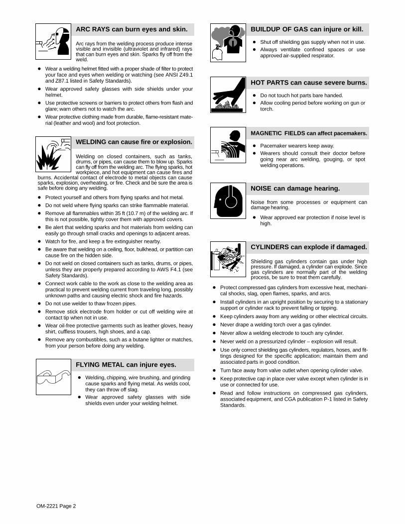
Arc rays from the welding process produce intensevisible and invisible (ultraviolet and infrared) raysthat can burn eyes and skin. Sparks fly off from theweld.
ARC RAYS can burn eyes and skin.
� Wear a welding helmet fitted with a proper shade of filter to protectyour face and eyes when welding or watching (see ANSI Z49.1and Z87.1 listed in Safety Standards).
� Wear approved safety glasses with side shields under yourhelmet.
� Use protective screens or barriers to protect others from flash andglare; warn others not to watch the arc.
� Wear protective clothing made from durable, flame-resistant mate-rial (leather and wool) and foot protection.
Welding on closed containers, such as tanks,drums, or pipes, can cause them to blow up. Sparkscan fly off from the welding arc. The flying sparks, hotworkpiece, and hot equipment can cause fires and
burns. Accidental contact of electrode to metal objects can causesparks, explosion, overheating, or fire. Check and be sure the area issafe before doing any welding.
WELDING can cause fire or explosion.
� Protect yourself and others from flying sparks and hot metal.
� Do not weld where flying sparks can strike flammable material.
� Remove all flammables within 35 ft (10.7 m) of the welding arc. Ifthis is not possible, tightly cover them with approved covers.
� Be alert that welding sparks and hot materials from welding caneasily go through small cracks and openings to adjacent areas.
� Watch for fire, and keep a fire extinguisher nearby.
� Be aware that welding on a ceiling, floor, bulkhead, or partition cancause fire on the hidden side.
� Do not weld on closed containers such as tanks, drums, or pipes,unless they are properly prepared according to AWS F4.1 (seeSafety Standards).
� Connect work cable to the work as close to the welding area aspractical to prevent welding current from traveling long, possiblyunknown paths and causing electric shock and fire hazards.
� Do not use welder to thaw frozen pipes.
� Remove stick electrode from holder or cut off welding wire atcontact tip when not in use.
� Wear oil-free protective garments such as leather gloves, heavyshirt, cuffless trousers, high shoes, and a cap.
� Remove any combustibles, such as a butane lighter or matches,from your person before doing any welding.
FLYING METAL can injure eyes.
� Welding, chipping, wire brushing, and grindingcause sparks and flying metal. As welds cool,they can throw off slag.
� Wear approved safety glasses with sideshields even under your welding helmet.
BUILDUP OF GAS can injure or kill.
� Shut off shielding gas supply when not in use.� Always ventilate confined spaces or use
approved air-supplied respirator.
HOT PARTS can cause severe burns.
� Do not touch hot parts bare handed.� Allow cooling period before working on gun or
torch.
MAGNETIC FIELDS can affect pacemakers.
� Pacemaker wearers keep away.� Wearers should consult their doctor before
going near arc welding, gouging, or spotwelding operations.
NOISE can damage hearing.
Noise from some processes or equipment candamage hearing.
� Wear approved ear protection if noise level ishigh.
Shielding gas cylinders contain gas under highpressure. If damaged, a cylinder can explode. Sincegas cylinders are normally part of the weldingprocess, be sure to treat them carefully.
CYLINDERS can explode if damaged.
� Protect compressed gas cylinders from excessive heat, mechani-cal shocks, slag, open flames, sparks, and arcs.
� Install cylinders in an upright position by securing to a stationarysupport or cylinder rack to prevent falling or tipping.
� Keep cylinders away from any welding or other electrical circuits.
� Never drape a welding torch over a gas cylinder.
� Never allow a welding electrode to touch any cylinder.
� Never weld on a pressurized cylinder – explosion will result.
� Use only correct shielding gas cylinders, regulators, hoses, and fit-tings designed for the specific application; maintain them andassociated parts in good condition.
� Turn face away from valve outlet when opening cylinder valve.
� Keep protective cap in place over valve except when cylinder is inuse or connected for use.
� Read and follow instructions on compressed gas cylinders,associated equipment, and CGA publication P-1 listed in SafetyStandards.

OM-2221 Page 3
1-3. Additional Symbols For Installation, Operation, And Maintenance
FIRE OR EXPLOSION hazard.
� Do not install or place unit on, over, or nearcombustible surfaces.
� Do not install unit near flammables.
� Do not overload building wiring – be sure power supply system isproperly sized, rated, and protected to handle this unit.
FALLING UNIT can cause injury.
� Use lifting eye to lift unit only, NOT runninggear, gas cylinders, or any other accessories.
� Use equipment of adequate capacity to lift andsupport unit.
� If using lift forks to move unit, be sure forks arelong enough to extend beyond opposite side ofunit.
OVERUSE can cause OVERHEATING
� Allow cooling period; follow rated duty cycle.� Reduce current or reduce duty cycle before
starting to weld again.� Do not block or filter airflow to unit.
STATIC (ESD) can damage PC boards.
� Put on grounded wrist strap BEFORE handlingboards or parts.
� Use proper static-proof bags and boxes tostore, move, or ship PC boards.
MOVING PARTS can cause injury.
� Keep away from moving parts.� Keep away from pinch points such as drive
rolls.
WELDING WIRE can cause injury.
� Do not press gun trigger until instructed to doso.
� Do not point gun toward any part of the body,other people, or any metal when threadingwelding wire.
MOVING PARTS can cause injury.
� Keep away from moving parts such as fans.� Keep all doors, panels, covers, and guards
closed and securely in place.
H.F. RADIATION can cause interference.
� High-frequency (H.F.) can interfere with radionavigation, safety services, computers, andcommunications equipment.
� Have only qualified persons familiar withelectronic equipment perform this installation.
� The user is responsible for having a qualified electrician prompt-ly correct any interference problem resulting from the installa-tion.
� If notified by the FCC about interference, stop using theequipment at once.
� Have the installation regularly checked and maintained.
� Keep high-frequency source doors and panels tightly shut, keepspark gaps at correct setting, and use grounding and shielding tominimize the possibility of interference.
ARC WELDING can cause interference.
� Electromagnetic energy can interfere withsensitive electronic equipment such ascomputers and computer-driven equipmentsuch as robots.
� Be sure all equipment in the welding area iselectromagnetically compatible.
� To reduce possible interference, keep weld cables as short aspossible, close together, and down low, such as on the floor.
� Locate welding operation 100 meters from any sensitive elec-tronic equipment.
� Be sure this welding machine is installed and groundedaccording to this manual.
� If interference still occurs, the user must take extra measuressuch as moving the welding machine, using shielded cables,using line filters, or shielding the work area.
1-4. Principal Safety Standards
Safety in Welding and Cutting, ANSI Standard Z49.1, from AmericanWelding Society, 550 N.W. LeJeune Rd, Miami FL 33126Safety and Health Standards, OSHA 29 CFR 1910, from Superinten-dent of Documents, U.S. Government Printing Office, Washington, D.C.20402.Recommended Safe Practices for the Preparation for Welding and Cut-ting of Containers That Have Held Hazardous Substances, AmericanWelding Society Standard AWS F4.1, from American Welding Society,550 N.W. LeJeune Rd, Miami, FL 33126National Electrical Code, NFPA Standard 70, from National Fire Protec-tion Association, Batterymarch Park, Quincy, MA 02269.
Safe Handling of Compressed Gases in Cylinders, CGA Pamphlet P-1,from Compressed Gas Association, 1235 Jefferson Davis Highway,Suite 501, Arlington, VA 22202.Code for Safety in Welding and Cutting, CSA Standard W117.2, fromCanadian Standards Association, Standards Sales, 178 RexdaleBoulevard, Rexdale, Ontario, Canada M9W 1R3.Safe Practices For Occupation And Educational Eye And FaceProtection, ANSI Standard Z87.1, from American National StandardsInstitute, 1430 Broadway, New York, NY 10018.Cutting And Welding Processes, NFPA Standard 51B, from NationalFire Protection Association, Batterymarch Park, Quincy, MA 02269.

OM-2221 Page 4
1-5. EMF Information
Considerations About Welding And The Effects Of Low FrequencyElectric And Magnetic FieldsWelding current, as it flows through welding cables, will cause electro-magnetic fields. There has been and still is some concern about suchfields. However, after examining more than 500 studies spanning 17years of research, a special blue ribbon committee of the NationalResearch Council concluded that: “The body of evidence, in thecommittee’s judgment, has not demonstrated that exposure to power-frequency electric and magnetic fields is a human-health hazard.”However, studies are still going forth and evidence continues to beexamined. Until the final conclusions of the research are reached, youmay wish to minimize your exposure to electromagnetic fields whenwelding or cutting.To reduce magnetic fields in the workplace, use the followingprocedures:
1. Keep cables close together by twisting or taping them.
2. Arrange cables to one side and away from the operator.
3. Do not coil or drape cables around your body.
4. Keep welding power source and cables as far away from opera-tor as practical.
5. Connect work clamp to workpiece as close to the weld as possi-ble.
About Pacemakers:Pacemaker wearers consult your doctor first. If cleared by your doctor,then following the above procedures is recommended.

OM-2221 Page 5
SECTION 1 – CONSIGNES DE SECURITE – LIRE AVANTUTILISATION
som _nd_fre 4/98
1-1. Signification des symboles
Signifie Mise en garde ! Soyez vigilant ! Cette procédureprésente des risques de danger ! Ceux-ci sont identifiéspar des symboles adjacents aux directives.
� Identifie un message de sécurité particulier.
� Signifie NOTA ; n’est pas relatif à la sécurité.
Ce groupe de symboles signifie Mise en garde ! Soyez vigilant ! Il y a desrisques de danger reliés aux CHOCS ÉLECTRIQUES, aux PIÈCES ENMOUVEMENT et aux PIÈCES CHAUDES. Reportez-vous aux symboleset aux directives ci-dessous afin de connaître les mesures à prendre pouréviter tout danger.
1-2. Dangers relatifs au soudage à l’arc
� Les symboles présentés ci-après sont utilisés tout au long duprésent manuel pour attirer votre attention et identifier les risquesde danger. Lorsque vous voyez un symbole, soyez vigilant etsuivez les directives mentionnées afin d’éviter tout danger. Lesconsignes de sécurité présentées ci-après ne font que résumerl’information contenue dans les normes de sécurité énuméréesà la section 1-4. Veuillez lire et respecter toutes ces normes desécurité.
� L’installation, l’utilisation, l’entretien et les réparations ne doi-vent être confiés qu’à des personnes qualifiées.
� Au cours de l’utilisation, tenir toute personne à l’écart et plus par-ticulièrement les enfants.
UN CHOC ÉLECTRIQUE peut tuer.
Un simple contact avec des pièces électriques peutprovoquer une électrocution ou des blessures graves.L’électrode et le circuit de soudage sont sous tensiondès que l’appareil est sur ON. Le circuit d’entrée et lescircuits internes de l’appareil sont également sous
tension à ce moment-là. En soudage semi-automatique ou automatique,le fil, le dévidoir, le logement des galets d’entraînement et les piècesmétalliques en contact avec le fil de soudage sont sous tension. Desmatériels mal installés ou mal mis à la terre présentent un danger.
� Ne jamais toucher les pièces électriques sous tension.� Porter des gants et des vêtements de protection secs ne comportant
pas de trous.� S’isoler de la pièce et de la terre au moyen de tapis ou d’autres
moyens isolants suffisamment grands pour empêcher le contact phy-sique éventuel avec la pièce ou la terre.
� Ne pas se servir de source électrique àcourant électrique dans les zoneshumides, dans les endroits confinés ou là où on risque de tomber.
� Se servir d’une source électrique àcourant électrique UNIQUEMENT si leprocédé de soudage le demande.
� Si l’utilisation d’une source électrique àcourant électrique s’avère néces-saire, se servir de la fonction de télécommande si l’appareil en est équipé.
� Couper l’alimentation ou arrêter le moteur avant de procéder à l’instal-lation, à la réparation ou à l’entretien de l’appareil. Déverrouillerl’alimentation selon la norme OSHA 29 CFR 1910.147 (voir normes desécurité).
� Installer et mettre à la terre correctement cet appareil conformément àson manuel d’utilisation et aux codes nationaux, provinciaux etmunicipaux.
� Toujours vérifier la terre du cordon d’alimentation – Vérifier et s’assu-rer que le fil de terre du cordon d’alimentation est bien raccordé à laborne de terre du sectionneur ou que la fiche du cordon est raccordéeà une prise correctement mise à la terre.
� En effectuant les raccordements d’entrée fixer d’abord le conducteurde mise à la terre approprié et contre-vérifier les connexions.
� Vérifier fréquemment le cordon d’alimentation pour voir s’il n’est pasendommagé ou dénudé – remplacer le cordon immédiatement s’il estendommagé – un câble dénudé peut provoquer une électrocution.
� Mettre l’appareil hors tension quand on ne l’utilise pas.� Ne pas utiliser des câbles usés, endommagés, de grosseur insuffi-
sante ou mal épissés.� Ne pas enrouler les câbles autour du corps.� Si la pièce soudée doit être mise à la terre, le faire directement avec un
câble distinct.� Ne pas toucher l’électrode quand on est en contact avec la pièce, la
terre ou une électrode provenant d’une autre machine.
� N’utiliser qu’un matériel en bon état. Réparer ou remplacer sur-le-champ les pièces endommagées. Entretenir l’appareil conformémentà ce manuel.
� Porter un harnais de sécurité quand on travaille en hauteur.
� Maintenir solidement en place tous les panneaux et capots.
� Fixer le câble de retour de façon à obtenir un bon contact métal-métalavec la pièce à souder ou la table de travail, le plus près possible de lasoudure.
� Isoler la pince de masse quand pas mis à la pièce pour éviter le contactavec tout objet métallique.
Il y a DU COURANT CONTINU IMPORTANT dans lesconvertisseurs après la suppression de l’alimenta-tion électrique.� Arrêter les convertisseurs, débrancher le courant électrique, et dé-
charger les condensateurs d’alimentation selon les instructionsindiquées dans la partie entretien avant de toucher les pièces.
Le soudage génère des fumées et des gaz. Leurinhalation peut être dangereux pour votre santé.
� Eloigner votre tête des fumées. Ne pas respirerles fumées.
� A l’intérieur, ventiler la zone et/ou utiliser un échappement au niveaude l’arc pour l’évacuation des fumées et des gaz de soudage.
� Si la ventilation est insuffisante, utiliser un respirateur à alimenta-tion d’air homologué.
� Lire les spécifications de sécurité des matériaux (MSDSs) et lesinstructions du fabricant concernant les métaux, les consomma-bles, les revêtements, les nettoyants et les dégraisseurs.
� Travailler dans un espace fermé seulement s’il est bien ventilé ou enportant un respirateur à alimentation d’air. Demander toujours à unsurveillant dûment formé de se tenir à proximité. Des fumées et desgaz de soudage peuvent déplacer l’air et abaisser le niveau d’oxy-gène provoquant des blessures ou des accidents mortels. S’assu-rer que l’air de respiration ne présente aucun danger.
� Ne pas souder dans des endroits situés à proximité d’opérations dedégraissage, de nettoyage ou de pulvérisation. La chaleur et lesrayons de l’arc peuvent réagir en présence de vapeurs et former desgaz hautement toxiques et irritants.
� Ne pas souder des métaux munis d’un revêtement, tels que l’aciergalvanisé, plaqué en plomb ou au cadmium à moins que le revête-ment n’ait été enlevé dans la zone de soudure, que l’endroit soit bienventilé, et si nécessaire, en portant un respirateur à alimentationd’air. Les revêtements et tous les métaux renfermant ces élémentspeuvent dégager des fumées toxiques en cas de soudage.
LES FUMÉES ET LES GAZ peuventêtre dangereux.

OM-2221 Page 6
Le rayonnement de l’arc du procédé de soudagegénère des rayons visibles et invisibles intenses(ultraviolets et infrarouges) susceptibles de provoquer
des brûlures dans les yeux et sur la peau. Des étincelles sont projetéespendant le soudage.
LES RAYONS DE L’ARC peuvent pro-voquer des brûlures dans les yeux etsur la peau.
� Porter un casque de soudage muni d’un écran de filtre approprié pourprotéger votre visage et vos yeux pendant le soudage ou pour regar-der (voir ANSI Z49.1 et Z87.1 énuméré dans les normes de sécurité).
� Porter des protections approuvés pour les oreilles si le niveau sondre esttrop élevé.
� Utiliser des écrans ou des barrières pour protéger des tiers de l’éclairet de l’éblouissement; demander aux autres personnes de ne pas re-garder l’arc.
� Porter des vêtements de protection constitué dans une matière dura-ble, résistant au feu (cuir ou laine) et une protection des pieds.
Le soudage effectué sur des conteneurs fermés telsque des réservoirs, tambours ou des conduites peutprovoquer leur éclatement. Des étincelles peuvent êtreprojetées de l’arc de soudure. La projection d’étincel-
les, des pièces chaudes et des équipements chauds peut provoquer desincendies et des brûlures. Le contact accidentel de l’électrode avec desobjets métalliques peut provoquer des étincelles, une explosion, unsurchauffement ou un incendie. Avant de commencer le soudage, vérifieret s’assurer que l’endroit ne présente pas de danger.
LE SOUDAGE peut provoquer unincendie ou une explosion.
� Se protéger et d’autres personnes de la projection d’étincelles et demétal chaud.
� Ne pas souder dans un endroit là où des étincelles peuvent tomber surdes substances inflammables.
� Déplacer toutes les substances inflammables à une distance de 10,7m de l’arc de soudage. En cas d’impossibilité les recouvrir soigneuse-ment avec des protections homologués.
� Des étincelles et des matériaux chauds du soudage peuvent facile-ment passer dans d’autres zones en traversant de petites fissures etdes ouvertures.
� Surveiller tout déclenchement d’incendie et tenir un extincteur à proxi-mité.
� Le soudage effectué sur un plafond, plancher, paroi ou séparationpeut déclencher un incendie de l’autre côté.
� Ne pas effectuer le soudage sur des conteneurs fermés tels que desréservoirs, tambours, ou conduites, à moins qu’ils n’aient été prépa-rés correctement conformément à AWS F4.1 (voir les normes desécurité).
� Brancher le câble sur la pièce le plus près possible de la zone de sou-dage pour éviter le transport du courant sur une longue distance pardes chemins inconnus éventuels en provoquant des risques d’élec-trocution et d’incendie.
� Ne pas utiliser le poste de soudage pour dégeler des conduites ge-lées.
� En cas de non utilisation, enlever la baguette d’électrode du porte-électrode ou couper le fil à la pointe de contact.
� Porter des vêtements de protection dépourvus d’huile tels que desgants en cuir, une chemise en matériau lourd, des pantalons sans re-vers, des chaussures hautes et un couvre chef.
� Avant de souder, retirer toute substance combustible de vos pochestelles qu’un allumeur au butane ou des allumettes.
DES PARTICULES VOLANTESpeuvent blesser les yeux.
� Le soudage, l’écaillement, le passage de la pièceà la brosse en fil de fer, et le meulage génèrentdes étincelles et des particules métalliques vo-
lantes. Pendant la période de refroidissement des soudures, elles ris-quent de projeter du laitier.� Porter des lunettes de sécurité avec écrans latéraux ou un écran facial.
LES ACCUMULATIONS DE GAZ ris-quent de provoquer des blessures oumême la mort.
� Fermer l’alimentation du gaz protecteur en cas denon utilisation.
� Veiller toujours à bien aérer les espaces confinés ou se servir d’un respi-rateur d’adduction d’air homologué.
DES PIÈCES CHAUDES peuvent pro-voquer des brûlures graves.
� Ne pas toucher des parties chaudes à mains nues� Prévoir une période de refroidissement avant
d’utiliser le pistolet ou la torche.
LES CHAMPS MAGNÉTIQUES peuventaffecter les stimulateurs cardiaques.
� Porteurs de stimulateur cardiaque, restez à distance.� Les porteurs d’un stimulateur cardiaque doivent
d’abord consulter leur médecin avant de s’approcherdes opérations de soudage à l’arc, de gougeage oude soudage par points.
LE BRUIT peut affecter l’ouïe.
Le bruit des processus et des équipements peut affecterl’ouïe.
� Porter des protections approuvés pour les oreilles sile niveau sondre est trop élevé.
Des bouteilles de gaz protecteur contiennent du gazsous haute pression. Si une bouteille est endomma-gée, elle peut exploser. Du fait que les bouteilles de gazfont normalement partie du procédé de soudage, les
manipuler avec précaution.
� Protéger les bouteilles de gaz comprimé d’une chaleur excessive,des chocs mécaniques, du laitier, des flammes ouvertes, des étin-celles et des arcs.
� Placer les bouteilles debout en les fixant dans un support stationnai-re ou dans un porte-bouteilles pour les empêcher de tomber ou dese renverser.
� Tenir les bouteilles éloignées des circuits de soudage ou autres cir-cuits électriques.
� Ne jamais placer une torche de soudage sur une bouteille à gaz.� Une électrode de soudage ne doit jamais entrer en contact avec une
bouteille.� Ne jamais souder une bouteille pressurisée – risque d’explosion.� Utiliser seulement des bouteilles de gaz protecteur, régulateurs,
tuyaux et raccords convenables pour cette application spécifique;les maintenir ainsi que les éléments associés en bon état.
� Ne pas tenir la tête en face de la sortie en ouvrant la soupape de labouteille.
� Maintenir le chapeau de protection sur la soupape, sauf en cas d’uti-lisation ou de branchement de la bouteille.
� Lire et suivre les instructions concernant les bouteilles de gaz com-primé, les équipements associés et les publications P-1 CGA énu-mérées dans les normes de sécurité.
Si des BOUTEILLES sont endomma-gées, elles pourront exploser.

OM-2221 Page 7
1-3. Dangers supplémentaires en relation avec l’installation, le fonctionnementet la maintenance
Risque D’INCENDIE OUD’EXPLOSION.
� Ne pas placer l’appareil sur, au-dessus ou à proxi-mité de surfaces infllammables.
� Ne pas installer l’appareil à proximité de produits inflammables� Ne pas surcharger l’installation électrique – s”assurer que l’alimen-
tation est correctement dimensionné et protégé avant de mettrel’appareil en service.
LA CHUTE DE L’APPAREIL peutblesser.
� Utiliser l’anneau de levage uniquement pour sou-lever l’appareil, NON PAS les chariot, les bouteil-les de gaz ou tout autre accessoire.
� Utiliser un engin d’une capacité appropriée poursoulever l’appareil.
� En utilisant des fourches de levage pour déplacer l’unité, s’assurerque les fourches sont suffisamment longues pour dépasser du côtéopposé de l’appareil.
L’EMPLOI EXCESSIF peutSURCHAUFFER L’ÉQUIPEMENT.
� Prévoir une période de refroidissement, respec-ter le cycle opératoire nominal.
� Réduire le courant ou le cycle opératoire avant derecommancer le soudage.
� Ne pas obstruer les passages d’air du poste.
LES CHARGES ÉLECTROSTATI-QUES peuvent endommager lescircuits imprimés.
� Établir la connexion avec la barrette de terreavant de manipuler des cartes ou des pièces.
� Utiliser des pochettes et des boîtes antistatiquespour stocker, déplacer ou expédier des cartes decircuits imprimes.
DES ORGANES MOBILES peuventprovoquer des blessures.
� Ne pas s’approcher des organes mobiles.� Ne pas s’approcher des points de coincement
tels que des rouleaux de commande.
LES FILS DE SOUDAGE peuventprovoquer des blessures.
� Ne pas appuyer sur la gachette avant d’en avoirreçu l’instruction.
� Ne pas diriger le pistolet vers soi, d’autres person-nes ou toute pièce mécanique en engageant le filde soudage.
DES ORGANES MOBILES peuventprovoquer des blessures.
� Rester à l’écart des organes mobiles comme leventilateur.
� Maintenir fermés et fixement en place les portes,panneaux, recouvrements et dispositifs deprotection.
LE RAYONNEMENT HAUTE FRÉ-QUENCE (H.F.) risque de provoquerdes interférences.
� Le rayonnement haute frequence peut provoquerdes interférences avec les équipements de ra-dio–navigation et de communication, les servicesde sécurité et les ordinateurs.
� Demander seulement à des personnes qualifiées familiariséesavec des équipements électroniques de faire fonctionner l’installa-tion.
� L’utilisateur est tenu de faire corriger rapidement par un électricienqualifié les interférences résultant de l’installation.
� Si le FCC signale des interférences, arrêter immédiatement l’appa-reil.
� Effectuer régulièrement le contrôle et l’entretien de l’installation.� Maintenir soigneusement fermés les portes et les panneaux des
sources de haute fréquence, maintenir les éclateurs à une distancecorrecte et utiliser une terre et et un blindage pour réduire les interfé-rences éventuelles.
LE SOUDAGE À L’ARC risque deprovoquer des interférences.
� L’énergie électromagnétique risque de provoquerdes interférences pour l’équipement électroniquesensible tel que les ordinateurs et l’équipementcommandé par ordinateur tel que les robots.
� Veiller à ce que tout l’équipement de la zone de soudage soit com-patible électromagnétiquement.
� Pour réduire la possibilité d’interférence, maintenir les câbles desoudage aussi courts que possible, les grouper, et les poser aussibas que possible (ex. par terre).
� Veiller à souder à une distance de 100 mètres de tout équipementélectronique sensible.
� Veiller à ce que ce poste de soudage soit posé et mis à la terreconformément à ce mode d’emploi.
� En cas d’interférences après avoir pris les mesures précédentes, ilincombe à l’utilisateur de prendre des mesures supplémentaires tel-les que le déplacement du poste, l’utilisation de câbles blindés, l’uti-lisation de filtres de ligne ou la pose de protecteurs dans la zone detravail.
LES CHAMPS MAGNÉTIQUES peuventaffecter les stimulateurs cardiaques.
� Porteurs de stimulateur cardiaque, restez à dis-tance.
� Les porteurs d’un stimulateur cardiaque doiventd’abord consulter leur médecin avant de s’appro-cher des opérations de soudage à l’arc, de gou-geage ou de soudage par points.

OM-2221 Page 8
1-4. Principales normes de sécurité
Safety in Welding and Cutting, norme ANSI Z49.1, de l’American Wel-ding Society, 550 N.W. Lejeune Rd, Miami FL 33126
Safety and Health Sandards, OSHA 29 CFR 1910, du Superintendentof Documents, U.S. Government Printing Office, Washington, D.C.20402.
Recommended Safe Practice for the Preparation for Welding and Cut-ting of Containers That Have Held Hazardous Substances, norme AWSF4.1, de l’American Welding Society, 550 N.W. Lejeune Rd, Miami FL33126
National Electrical Code, NFPA Standard 70, de la National Fire Protec-tion Association, Batterymarch Park, Quincy, MA 02269.
Safe Handling of Compressed Gases in Cylinders, CGA Pamphlet P-1,de la Compressed Gas Association, 1235 Jefferson Davis Highway,Suite 501, Arlington, VA 22202.
Règles de sécurité en soudage, coupage et procédés connexes, normeCSA W117.2, de l’Association canadienne de normalisation, vente denormes, 178 Rexdale Boulevard, Rexdale (Ontario) Canada M9W 1R3.
Safe Practices For Occupation And Educational Eye And Face Protec-tion, norme ANSI Z87.1, de l’American National Standards Institute,1430 Broadway, New York, NY 10018.
Cutting and Welding Processes, norme NFPA 51B, de la National FireProtection Association, Batterymarch Park, Quincy, MA 02269.
1-5. Information sur les champs électromagnétiques
Données sur le soudage électrique et sur les effets, pour l’organisme,des champs magnétiques basse fréquence
Le courant de soudage, pendant son passage dans les câbles de sou-dage, causera des champs électromagnétiques. Il y a eu et il y a encoreun certain souci à propos de tels champs. Cependant, après avoir ex-aminé plus de 500 études qui ont été faites pendant une période derecherche de 17 ans, un comité spécial ruban bleu du National Re-search Council a conclu: “L’accumulation de preuves, suivant lejugement du comité, n’a pas démontré que l’exposition aux champsmagnétiques et champs électriques à haute fréquence représente unrisque à la santé humaine”. Toutefois, des études sont toujours en courset les preuves continuent à être examinées. En attendant que les con-clusions finales de la recherche soient établies, il vous seraitsouhaitable de réduire votre exposition aux champs électromagnéti-ques pendant le soudage ou le coupage.
Afin de réduire les champs électromagnétiques dans l’environnementde travail, respecter les consignes suivantes :
1 Garder les câbles ensembles en les torsadant ou en lesattachant avec du ruban adhésif.
2 Mettre tous les câbles du côté opposé de l’opérateur.
3 Ne pas courber pas et ne pas entourer pas les câbles autour devotre corps.
4 Garder le poste de soudage et les câbles le plus loin possible devous.
5 Relier la pince de masse le plus près possible de la zone desoudure.
Consignes relatives aux stimulateurs cardiaques :
Les personnes qui portent un stimulateur cardiaque doivent avant toutconsulter leur docteur. Si vous êtes déclaré apte par votre docteur, il estalors recommandé de respecter les consignes ci–dessus.

OM-2221 Page 9
SECTION 2 – INSTALLATION
With 60 Hz input power, the ac weld output of this unit is 10 Hz. With 50 Hz input,the ac weld output is 8.33 Hz.
NOTE
2-1. Specifications
RMS Amps Input at Rated Load Output,3-Phase at NEMA Load
Voltages and Class I Rating
AC or DCRated Output
Voltage Range in CV Mode
AmperageRange inCC Mode
Max. Open-CircuitVoltage
380/400/415 V(50/60 Hz)
460 V(60 Hz)
575 V(60 Hz) KVA KW
1000 A at 44 V, 100% Duty Cycle; 143 124 100 98 53100% Duty Cycle;
1250 A at 44 V,60% Duty Cycle
25–44 V 250–1250 A 71 V143(3*)
124(3*)
100(3*)
98(2.37*)
53(0.95*)
*While idling
2-2. Duty Cycle and OverheatingDuty Cycle is percentage of 10 min-utes that unit can weld at rated loadwithout overheating.
If unit overheats, high temperatureshutdown light turns On, thermo-stat(s) opens, output stops, andcooling fan runs. Wait fifteen min-utes for unit to cool. Reduce amper-age or duty cycle before welding.
� Exceeding duty cycle candamage unit and void war-ranty.
Overheating0
15
A/V
ORReduce Duty CycleMinutes
duty1 4/95 – SA-181 560
Continuous Welding
100% Duty Cycle At 1000 Amperes

OM-2221 Page 10
2-3. Volt-Ampere Curves
va_curve1 4/95 – SA-189 242 / SA-189 240 / SA-189 243 / SA-189 241
Volt-ampere curves show minimumand maximum voltage and amper-age output capabilities of unit.Curves of other settings fall be-tween curves shown.
A. CC Mode
B. CV Mode
DC Output AC Output
DC Output AC Output

OM-2221 Page 11
2-4. Dimensions And Weight
DimensionsA
Height* 44 in (1118 mm)
Width* 27-1/4 in (692 mm)
Depth* 46 in (1168 mm)1225 lb (540 kg)
Weight
A 1-7/8 in (48 mm) B
B 44-1/8 in (1120 mm)
C 11/16 in (17 mm)
D 26-1/16 in (662 mm) E
E4 holes: 21/32 in (6.5 mm) dia
C
Front
D
* Includes lifting eye, handles, hardware, etc.
2-5. Symbol Definitions
Some symbols are found only on CE products.NOTE
A Amperage V Voltage Hz HertzDirect Current
(DC)
Alternating Current(AC) Panel/Local Line Connection Three Phase
Output On Voltage Input Off
Submerged ArcWelding (SAW)
Read Operator’sManual Remote X Duty Cycle
Percent U0Rated No-Load
Voltage (Average) U1Rated Supply
Voltage Circuit Breaker
U2Conventional Load
Voltage I2Rated Welding
CurrentProtective Earth
(Ground) I1maxRated MaximumSupply Current
I1effMaximum Effective
Supply Current
3-Phase PowerSource With
AC/DC OutputTemperature
Ventilating And AirCirculating Fan
Increase IP Degree OfProtection
Air Carbon ArcCutting (CAC-A)
Shielding Metal ArcWelding (SMAW)
Gas Metal ArcWelding GMAW)

OM-2221 Page 12
2-6. Manufacturer ’s Rating Label For CE Products
2-7. Selecting a Location
loc_2 3/96 - ST-801 881-A
1 Lifting Eye
2 Lifting Forks
Use lifting eye or lifting forks tomove unit.
If using lifting forks, extend forksbeyond opposite side of unit.
3 Rating Label
4 Plate Label
Use rating or plate label to deter-mine input power needs.
5 Line Disconnect Device
Locate unit near correct inputpower supply.
� Special installation may berequired where gasoline orvolatile liquids are present –see NEC Article 511 or CECSection 20.
OR
1Movement
2
Location
18 in
5
(460 mm)
18 in(460 mm)
3
4

OM-2221 Page 13
2-8. Weld Output Terminals and Selecting Cable Sizes
In the table below, when multiple numbers are indicated separated by a hyphen,the number to the left of the hyphen indicates how many cables are to be used, andthe number to the right indicates the size of the cable to be used. For example,3-3/0 indicates that 3 cables of 3/0 gauge need to be used for electrode and workconnections.
NOTE
Total Cable (Copper) Length In Weld Circuit Not Exceeding
Weld OutputTerminals 100 ft (30 m) Or Less
150 ft(45 m)
200 ft(60 m)
250 ft(70 m)
300 ft(90 m)
350 ft(105 m)
400 ft(120 m)
� Turn Off welding pow-er source and disconnectinput power before con-
necting to weld output ter-minals.
WeldingAmperes
10 – 60%Duty Cycle
60 – 100%Duty Cycle 10 – 100% Duty Cycle
100 4 4 4 3 2 1 1/0 1/0
150 3 3 2 1 1/0 2/0 3/0 3/0
200 3 2 1 1/0 2/0 3/0 4/0 4/0
250 2 1 1/0 2/0 3/0 4/0 2-2/0 2-2/0
300 1 1/0 2/0 3/0 4/0 2-2/0 2-3/0 2-3/0
350 1/0 2/0 3/0 4/0 2-2/0 2-3/0 2-3/0 2-4/0
400 1/0 2/0 3/0 4/0 2-2/0 2-3/0 2-4/0 2-4/0
WorkElectrode 500 2/0 3/0 4/0 2-2/0 2-3/0 2-4/0 3-3/0 3-3/0Weld Output
TerminalsWeld Output
Terminals 600 3/0 4/0 2-2/0 2-3/0 2-4/0 3-3/0 3-4/0 3-4/0
Requires cable lugs with 700 4/0 2-2/0 2-3/0 2-4/0 3-3/0 3-4/0 3-4/0 4-4/05/8 in diameter holes.
15/16 in800 4/0 2-2/0 2-3/0 2-4/0 3-4/0 3-4/0 4-4/0 4-4/0
15/16 in900 2-2/0 2-3/0 2-4/0 3-3/0 3-4/0 4-4/0 4-4/0
1000 2-2/0 2-3/0 2-4/0 3-3/0 4-3/0 4-4/0
1250 2-3/0 2-4/0 3-3/0 4-3/0 4-4/0
*Weld cable size (AWG) is based on either a 4 volts or less drop or a current density of at least 300 circular mils per ampere. Contact yourdistributor for the mm2 equivalent weld cable sizes. S-0007-E

OM-2221 Page 14
2-9. Selecting AC or DC Output� Turn Off welding power
source and disconnect inputpower before relinking unit.
Remove top of unit.
1 AC/DC Output SelectionLabel (Located Inside Unit)
2 Jumper Links
Locate terminal board inside unit.Install jumper links for desired out-put as shown on label.
� Securing nuts must be re-moved to change the positionof the three jumper links at theright of the terminal board. Tochange the position of the re-maining six jumper links, loos-en the securing nuts only to al-low the slotted jumper links tobe moved. Always securely re-tighten nuts after links aremoved.
Reinstall top of unit.
ST-801 881-A / Ref. S-185 482
ÏÏÏÏ
ÏÏÏÏÏÏÏÏ
ÏÏÏÏ
ÏÏÏÏÏÏ
ÏÏ
ÏÏÏÏÏ
ÏÏ
ÏÏÏ
ÏÏ
ÏÏ
ÏÏ
ÏÏ
ÏÏ
ÏÏ
AC
DC
1
2
� See Safety Rules at beginning ofmanual for special ac concerns.
Tools Needed:
3/8, 11/16, 7/8 in
2-10. Terminal Strip TE3 and Remote 14 Receptacle RC7 Information
Socketon RC7
Terminalon TE3
Information
A A 24 volts, 12 amperes, 60 Hz ac. Protected by circuit breaker CB2.24 VOLTS AC B B Contact closure to A completes 24 volts ac contactor control circuit.
C C Command reference; +10 volts dc.
REMOTE OUTPUT CONTROL D D Remote control circuit common.
E E 0 to +10 volts dc input command signal from remote control.
I I 115 volts, 12 amperes, 60 Hz ac. Protected by circuit breaker CB1.115 VOLTS AC
J J Contact closure to I completes 115 volts ac contactor control circuit.
GNDK
G
K
G
Chassis common.
Circuit common for 24, 42 and 115 volts ac circuits.
42 VOLTS AC * L 42 volts, 12 amperes, 60 Hz ac. Protected by circuit breaker CB3.
A/V AMPERAGE F * Current feedback; +1 volt dc per 100 amperes.A/V AMPERAGEVOLTAGE H * Voltage feedback; +1 volt dc per 10 output terminal volts.
* N Voltage sensing signal from Work weld output terminal.REMOTE VOLTAGE SENSING
* P Voltage sensing signal from Electrode weld output terminal.
* Not Used
OM-2221 Page 15
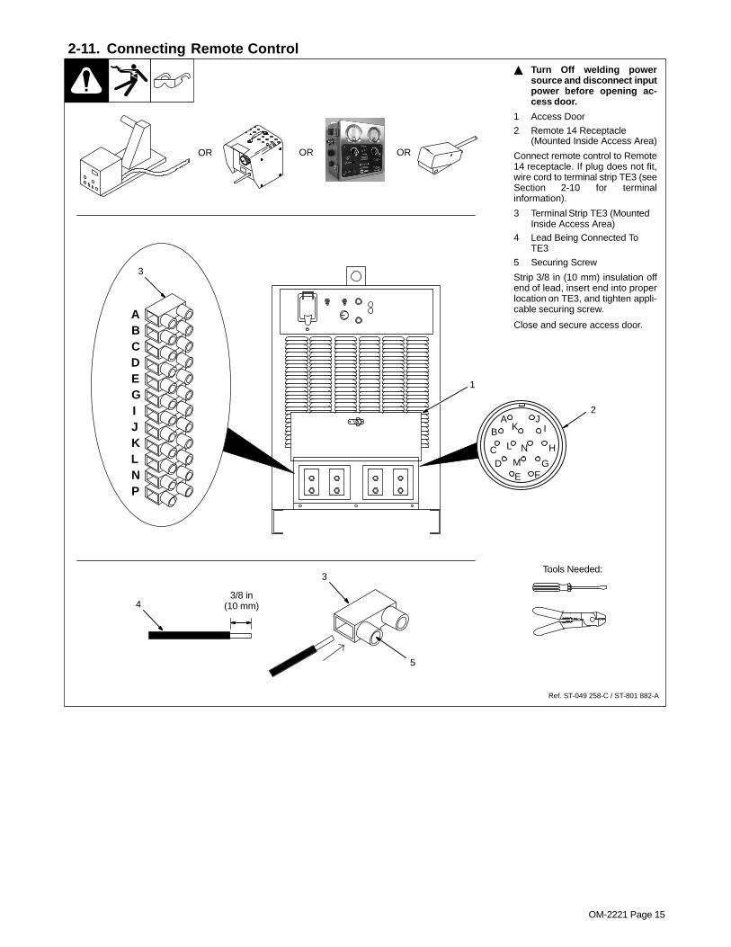
2-11. Connecting Remote Control
Ref. ST-049 258-C / ST-801 882-A
� Turn Off welding powersource and disconnect inputpower before opening ac-cess door.
1 Access Door
2 Remote 14 Receptacle(Mounted Inside Access Area)
Connect remote control to Remote14 receptacle. If plug does not fit,wire cord to terminal strip TE3 (seeSection 2-10 for terminalinformation).
3 Terminal Strip TE3 (MountedInside Access Area)
4 Lead Being Connected ToTE3
5 Securing Screw
Strip 3/8 in (10 mm) insulation offend of lead, insert end into properlocation on TE3, and tighten appli-cable securing screw.
Close and secure access door.
2
OR OR
A JB K I
C L N H
D M GE F
1
3
4
5
3Tools Needed:
3/8 in(10 mm)
ABCDEGIJKLNP
OR
OM-2221 Page 16
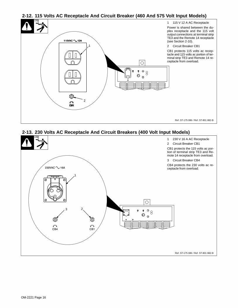
2-12. 115 Volts AC Receptacle And Circuit Breaker (460 And 575 Volt Input Models)1 115 V 12 A AC Receptacle
Power is shared between the du-plex receptacle and the 115 voltoutput connections at terminal stripTE3 and the Remote 14 receptacle(see Section 2-10).
2 Circuit Breaker CB1
CB1 protects 115 volts ac recep-tacle and 115 volts ac portion of ter-minal strip TE3 and Remote 14 re-ceptacle from overload.
1
Ref. ST-175 086 / Ref. ST-801 882-B
2
2-13. 230 Volts AC Receptacle And Circuit Breakers (400 Volt Input Models)1 230 V 16 A AC Receptacle
2 Circuit Breaker CB1
CB1 protects the 115 volts ac por-tion of terminal strip TE3 and Re-mote 14 receptacle from overload.
3 Circuit Breaker CB4
CB4 protects the 230 volts ac re-ceptacle from overload.
1
Ref. ST-175 086 / Ref. ST-801 882-B
3 2

OM-2221 Page 17
2-14. Electrical Service Guide
Three-Phase, 50/60 Hz Three-Phase, 60 Hz
Input Voltage 380/400/415 460 575
Input Amperes At Rated Output 143 124 100
Max Recommended Standard Fuse Or Circuit Breaker Rating In Amperes 200 175 150
Min Input Conductor Size In AWG/Kcmil 1/0 1 2
Max Recommended Input Conductor Length In Feet (Meters) 382 (116) 417 (127) 575 (175)
Min Grounding Conductor Size In AWG/Kcmil 6 6 6
Reference: 1997 National Electrical Code (NEC). S-0092-J
2-15. Connecting Input Power
L1
input_2 3/96 - Ref. ST-144 221 / Ref. ST-801 883-B
� Disconnect and lockout/tag-out input power before con-necting input conductorsfrom unit.
� Have only qualified personsmake this installation.
Check input voltage available atsite.
Remove left side panel.
1 Input And GroundingConductors
2 Line Disconnect Device OfProper Rating
See Section 2-14.
3 Access Hole And Strain ReliefConnector
4 Input Conductors
5 Grounding Conductor (Greenor Green With Yellow Stripe)
Insert conductors through strain re-lief.
6 Three-Phase Input Contactor
7 Ground Terminal
Connect grounding conductor toground terminal on frame first. Thenconnect input conductors to line ter-minals on contactor. Secure strainrelief on input power cable.
Install and connect grounding con-ductor and input conductors in con-duit or equivalent to deenergizedline disconnect device.
Be sure grounding conductor goesto an earth ground.
Reinstall side panel.
3/8 in
2
1
L2
L3
� Always connectgroundingconductor first.
= GND/PE
Tools Needed:
1
3
57
7/16 in
3/16 in
6
4
L1
L2 L3
� When using multiple units whichwill be linked with the synchro-nizing terminal strip TE4, ensurethat primary input power con-ductors are connected to eachunit in the same sequence (L1 toL1, L2 to L2, and L3 to L3.)
� See Section 2-16 for information ontesting for proper primary phasesequence.

OM-2221 Page 18
Unit B(Slave)
2-16. Matching Primary Lines L1, L2, And L3 When Using Multiple Units� Turn Off welding power
source and disconnect inputpower before opening ac-cess door.
This test must be performed on theunits that will be interconnected us-ing the synchronizing terminal stripTE4. This refers to the multiple unithook-ups shown in Sections 3-2,3-3, and 3-5.
Power On both units. Using an acvoltmeter, measure the voltage be-tween terminal A of terminal stripTE3 on both units as shown.
If the measured voltage is 0 (zero)volts, the primary lines are properlyphased.
If the measured voltage is 48 volts,swap the input conductor connec-tions to L1 and L3 on the primary in-put contactor of unit B.
If the measured voltage is 42 volts,swap L1 and L2 on the primary inputcontactor of unit B. The meter willthen read either 48 volts or 24 volts.If the meter reads 48 volts, swap L1and L3. If the meter reads 24 volts,swap L2 and L3.
If the measured voltage is 24 volts,swap L1 and L2 on the primary inputcontactor of unit B. The meter willthen read either 0 (zero) volts or 42volts. If the meter reads 0 volts, theprimary lines are properly phased.If the meter reads 42 volts, swap L1and L2 again, and swap L2 and L3.
When the second (slave) unit’s pri-mary line phase sequences arematched with the first (master) unit,test primary phasing between thirdunit (if applicable) and second unit.Always test and correct phasingbetween following unit and unit pre-vious to it.
Set on AC Volts Scale
Meter Polarity Does Not Matter
Ref. ST-801 882-A / Ref. 801 883-B
Unit A(Master)
L1
L2 L3
ABCDEGIJKLNP
Terminal StripTE3
ABCDEGIJKLNP
Terminal StripTE3
Input Contactor

OM-2221 Page 19
SECTION 3 – MAKING WELD OUTPUT CONNECTIONS
3-1. Work And Electrode Cable Connections For Single DC or AC Arcs� Turn Off welding power
source and disconnect inputpower before opening ac-cess door.
For dc electrode positive:
Connect the proper size and num-ber of weld output cables (see Sec-tion 2-8) to one of the welding powersource electrode terminals.
Connect the proper size and num-ber of ground cables to one of thewelding power source work termi-nals.
For dc electrode negative:
Connect the proper size and num-ber of weld output cables (see Sec-tion 2-8) to one of the welding powersource work terminals.
Connect the proper size and num-ber of ground cables to one of thewelding power source electrodeterminals.
For ac output:
Connect the proper size and num-ber of weld output cables (see Sec-tion 2-8) to one of the welding powersource electrode terminals.
Connect the proper size and num-ber of ground cables to one of thewelding power source work termi-nals.
� If there are any questions regardingthis procedure, contact the factory be-fore connecting units.
� High weld output current hazard! Remove all metal jewelry, such asrings and watches, and be careful with tools near output terminals.High current can cause severe burns from hot metal if touched tooutput terminals and unit is On. ALWAYS turn Off welding powersources and disconnect input power BEFORE making weld outputconnections.
� UNDERSIZED WELD CABLES can cause fire.
Work cable or electrode cable must be able to carry the weld output of the individual welding powersource (see Section 2-8).
Do not exceed duty cycle of welding power sources.
� ELECTRIC SHOCK can kill.
Do not touch live electrical parts.
Turn off welding power sources and disconnect input power before making any weld output con-nections.
See ANSI Z49.1 and OSHA Title 29, Chapter XVII, Part 1910, Subpart Q (addresses at begin-ning of manual).
Do not handle or come in contact with two live electrodes at the same time.
Connections For DC Electrode Positive
Or AC Output
Connections For DC Electrode
Negative Output
ST-801 882-A
To Electrode
To Work
To Work
To Electrode

OM-2221 Page 20
3-2. Using Multiple Units: DC Lead Arc, One or More AC Trailing Arcs With Separate Electrodes
� Turn Off welding powersource and disconnect inputpower before opening ac-cess door.
To use a dc electrode positive leadarc with one or more trailing ac arcs,make connections as shown.
When running more than one actrailing arc, set up the ac units ac-cording to Section 3-6 or 3-7, as ap-plicable.
� When using multiple arcs inparallel, be sure to followunit setup instructions care-fully. Severe damage to unitsmay occur if units are notcorrectly connected for par-allel operation.
� If there are any questions regardingthis procedure, contact the factory be-fore connecting units.
ToDC Output Elec-
trode #1
DC Output UnitConnections
First AC Output UnitConnections
To ACOutput
Electrode #3
To ACOutput
Electrode #2
� High weld output current hazard! Remove all metal jewelry, such as ringsand watches, and be careful with tools near output terminals. High cur-rent can cause severe burns from hot metal if touched to output terminalsand unit is On. ALWAYS turn Off welding power sources and disconnectinput power BEFORE making weld output connections.
� UNDERSIZED WELD CABLES can cause fire.
Work cable or electrode cable must be able to carry the weld output of the individual welding powersource (see Section 2-8).
Securely cover common connections with proper insulating material as shown in detail below.
Do not exceed duty cycle of welding power sources.
� ELECTRIC SHOCK can kill.
Do not touch live electrical parts.
Turn off welding power sources and disconnect input power before making any weld output con-nections.
See ANSI Z49.1 and OSHA Title 29, Chapter XVII, Part 1910, Subpart Q (addresses at begin-ning of manual).
Do not handle or come in contact with two live electrodes at the same time.
ST-801 882-A
Shielded Cable To Terminal Strip TE4
To Next ACUnit
Second AC Output Unit(And Following Units)
ConnectionsTo Work To Work To Work
OM-2221 Page 21
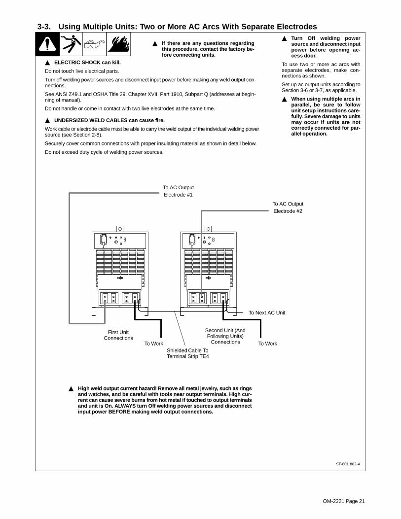
3-3. Using Multiple Units: Two or More AC Arcs With Separate Electrodes� Turn Off welding power
source and disconnect inputpower before opening ac-cess door.
To use two or more ac arcs withseparate electrodes, make con-nections as shown.
Set up ac output units according toSection 3-6 or 3-7, as applicable.
� When using multiple arcs inparallel, be sure to followunit setup instructions care-fully. Severe damage to unitsmay occur if units are notcorrectly connected for par-allel operation.
To AC OutputElectrode #1
First UnitConnections
Second Unit (AndFollowing Units)
Connections
To AC OutputElectrode #2
� High weld output current hazard! Remove all metal jewelry, such as ringsand watches, and be careful with tools near output terminals. High cur-rent can cause severe burns from hot metal if touched to output terminalsand unit is On. ALWAYS turn Off welding power sources and disconnectinput power BEFORE making weld output connections.
� If there are any questions regardingthis procedure, contact the factory be-fore connecting units.
� UNDERSIZED WELD CABLES can cause fire.
Work cable or electrode cable must be able to carry the weld output of the individual welding powersource (see Section 2-8).
Securely cover common connections with proper insulating material as shown in detail below.
Do not exceed duty cycle of welding power sources.
� ELECTRIC SHOCK can kill.
Do not touch live electrical parts.
Turn off welding power sources and disconnect input power before making any weld output con-nections.
See ANSI Z49.1 and OSHA Title 29, Chapter XVII, Part 1910, Subpart Q (addresses at begin-ning of manual).
Do not handle or come in contact with two live electrodes at the same time.
ST-801 882-A
Shielded Cable To Terminal Strip TE4
To Next AC Unit
To Work To Work
OM-2221 Page 22
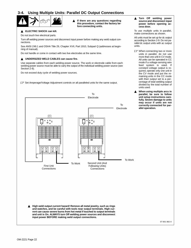
3-4. Using Multiple Units: Parallel DC Output Connections� Turn Off welding power
source and disconnect inputpower before opening ac-cess door.
To use multiple units in parallel,make connections as shown.
All units must be set up for dc outputaccording to Section 2-9. Do not pa-rallel dc output units with ac outputunits.
� When connecting two or moreunits in parallel, do not usemore than one unit in CV mode.All units can be operated in CCmode if a voltage-sensing wirefeed system is used. Ifconstant voltage output is re-quired, operate only one unit inthe CV mode and put the re-maining units in the CC modewith their output set to a per-centage of total welding outputdivided by the total number ofunits used.
� When using multiple arcs inparallel, be sure to followunit setup instructions care-fully. Severe damage to unitsmay occur if units are notcorrectly connected for par-allel operation.
To Work
ToElectrode
First UnitConnections
Second Unit (AndFollowing Units)
Connections
� High weld output current hazard! Remove all metal jewelry, such as ringsand watches, and be careful with tools near output terminals. High cur-rent can cause severe burns from hot metal if touched to output terminalsand unit is On. ALWAYS turn Off welding power sources and disconnectinput power BEFORE making weld output connections.
� If there are any questions regardingthis procedure, contact the factory be-fore connecting units.
� Set Amperage/Voltage Adjustment controls on all paralleled units for the same output.
� UNDERSIZED WELD CABLES can cause fire.
Use separate cables from each welding power source. The work or electrode cable from eachwelding power source must be able to carry the output of the individual welding power source (seeSection 2-8).
Do not exceed duty cycle of welding power sources.
� ELECTRIC SHOCK can kill.
Do not touch live electrical parts.
Turn off welding power sources and disconnect input power before making any weld output con-nections.
See ANSI Z49.1 and OSHA Title 29, Chapter XVII, Part 1910, Subpart Q (addresses at begin-ning of manual).
Do not handle or come in contact with two live electrodes at the same time.
ToElectrode
To Work
ST-801 882-A

OM-2221 Page 23
3-5. Using Multiple Units: Parallel AC Output Connections� Turn Off welding power
source and disconnect inputpower before opening ac-cess door.
� Always test for correct phas-ing before paralleling ac out-puts according to Section3-9.
To use multiple units in parallel,make connections as shown.
All units must be set up for ac outputaccording to Section 2-9. Do notparallel dc output units with ac out-put units.
The welding power source outputsmust be synchronized according toSection 3-6.
� When connecting two or moreunits in parallel, do not usemore than one unit in CV mode.All units can be operated in CCmode if a voltage-sensing wirefeed system is used. Ifconstant voltage output is re-quired, operate only one unit inthe CV mode and put the re-maining units in the CC modewith their output set to a per-centage of total welding outputdivided by the total number ofunits used.
� When using multiple arcs inparallel, be sure to followunit setup instructions care-fully. Severe damage to unitsmay occur if units are notcorrectly connected for par-allel operation.
� High weld output current hazard! Remove all metal jewelry, such as ringsand watches, and be careful with tools near output terminals. High cur-rent can cause severe burns from hot metal if touched to output terminalsand unit is On. ALWAYS turn Off welding power sources and disconnectinput power BEFORE making weld output connections.
� If there are any questions regardingthis procedure, contact the factory be-fore connecting units.
� Set Amperage/Voltage Adjustment controls on all paralleled units for the same output.
� UNDERSIZED WELD CABLES can cause fire.
Use separate cables from each welding power source. The work or electrode cable from eachwelding power source must be able to carry the output of the individual welding power source (seeSection 2-8).
Do not exceed duty cycle of welding power sources.
� ELECTRIC SHOCK can kill.
Do not touch live electrical parts.
Turn off welding power sources and disconnect input power before making any weld output con-nections.
See ANSI Z49.1 and OSHA Title 29, Chapter XVII, Part 1910, Subpart Q (addresses at begin-ning of manual).
Do not handle or come in contact with two live electrodes at the same time.
To Work
ToElectrode
First UnitConnections
Second Unit (AndFollowing Units)
Connections
ToElectrode
To Work
ST-801 882-A
Shielded Cable To Terminal Strip TE4(See Section 3-6)
To Next AC Unit

OM-2221 Page 24
3-6. Synchronizing Outputs For Parallel AC Arcs
� Turn Off welding powersource and disconnect inputpower before opening ac-cess door.
1 Terminal Strip TE4
This procedure allows the ac out-puts of two or more units to be syn-chronized so the waveformsmatch. To synchronize outputs,make connections between termi-nal strip TE4 on each ac output unitas shown in illustration.
� Do not disturb factory connec-tions to terminal strip TE4.
� Ensure that primary inputpower conductors are con-nected to each unit in thesame sequence (L1 to L1, L2to L2, and L3 to L3). See Sec-tion 2-15 for information onconnecting input power. SeeSection 2-16 for informationon testing for proper primaryphase sequence.
� Always test for correct phas-ing before paralleling ac out-puts according to Section3-9.
2 Lead Being Connected ToTE4
3 Securing Screw
Strip 3/8 in (10 mm) insulation offend of lead, insert end into properlocation on TE4, and tighten appli-cable securing screw.
Close and secure access door.
� Make certain control boardPC1 is set for synchronizedparallel ac arcs (see Section3-8).
� If there are any questions regarding this procedure, contact the factory before connecting units.
2
3
1
ToolsNeeded:
3/8 in(10 mm)
ABC
Connections from first to secondwelding power source:
terminal A to terminal E,terminal B to terminal B,terminal C to terminal C
1
� All synchronized units must be set up for ac output ac-cording to Section 2-9. Do not mix dc and ac output units.
DE
ABCDE
ABCDE
ABCDE
ABCDE
Terminal Strip TE4 Connections For Operating Multiple AC Units In Parallel
TE4 on firstwelding power
source
TE4 on secondwelding power
source
TE4 on thirdwelding power
source
Repeat same connection se-quence on following
welding power sources
Connections from second to thirdwelding power source:
terminal A to terminal E,terminal B to terminal B,terminal C to terminal C
Connections from third to fourthwelding power source:
terminal A to terminal E,terminal B to terminal B,terminal C to terminal C
ST-801 882-A
� Use two-conductor (12 to 20 gauge), with uninsulated ground,shielded cable to make TE4 connections. Connect ground toterminal C on TE4.
� When using multiple arcs inparallel, be sure to followunit setup instructions care-fully. Severe damage to unitsmay occur if units are notcorrectly connected for par-allel operation.
OM-2221 Page 25
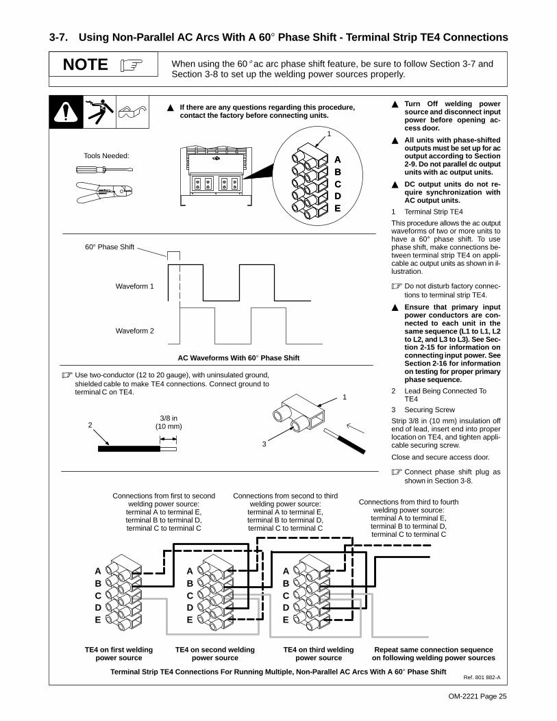
3-7. Using Non-Parallel AC Arcs With A 60� Phase Shift - Terminal Strip TE4 Connections
When using the 60� ac arc phase shift feature, be sure to follow Section 3-7 andSection 3-8 to set up the welding power sources properly.
NOTE
� Turn Off welding powersource and disconnect inputpower before opening ac-cess door.
� All units with phase-shiftedoutputs must be set up for acoutput according to Section2-9. Do not parallel dc outputunits with ac output units.
� DC output units do not re-quire synchronization withAC output units.
1 Terminal Strip TE4
This procedure allows the ac outputwaveforms of two or more units tohave a 60° phase shift. To usephase shift, make connections be-tween terminal strip TE4 on appli-cable ac output units as shown in il-lustration.
� Do not disturb factory connec-tions to terminal strip TE4.
� Ensure that primary inputpower conductors are con-nected to each unit in thesame sequence (L1 to L1, L2to L2, and L3 to L3). See Sec-tion 2-15 for information onconnecting input power. SeeSection 2-16 for informationon testing for proper primaryphase sequence.
2 Lead Being Connected ToTE4
3 Securing Screw
Strip 3/8 in (10 mm) insulation offend of lead, insert end into properlocation on TE4, and tighten appli-cable securing screw.
Close and secure access door.
� Connect phase shift plug asshown in Section 3-8.
� If there are any questions regarding this procedure, contact the factory before connecting units.
Tools Needed: ABC
1
DE
ABCDE
Terminal Strip TE4 Connections For Running Multiple, Non-Parallel AC Arcs With A 60� Phase Shift
AC Waveforms With 60� Phase Shift
Waveform 1
Waveform 2
60° Phase Shift
Connections from first to secondwelding power source:
terminal A to terminal E,terminal B to terminal D,terminal C to terminal C
ABCDE
ABCDE
ABCDE
TE4 on first weldingpower source
TE4 on second weldingpower source
TE4 on third weldingpower source
Repeat same connection sequenceon following welding power sources
Connections from second to thirdwelding power source:
terminal A to terminal E,terminal B to terminal D,terminal C to terminal C
Connections from third to fourthwelding power source:
terminal A to terminal E,terminal B to terminal D,terminal C to terminal C
Ref. 801 882-A
2
3
1
3/8 in(10 mm)
� Use two-conductor (12 to 20 gauge), with uninsulated ground,shielded cable to make TE4 connections. Connect ground toterminal C on TE4.
OM-2221 Page 26
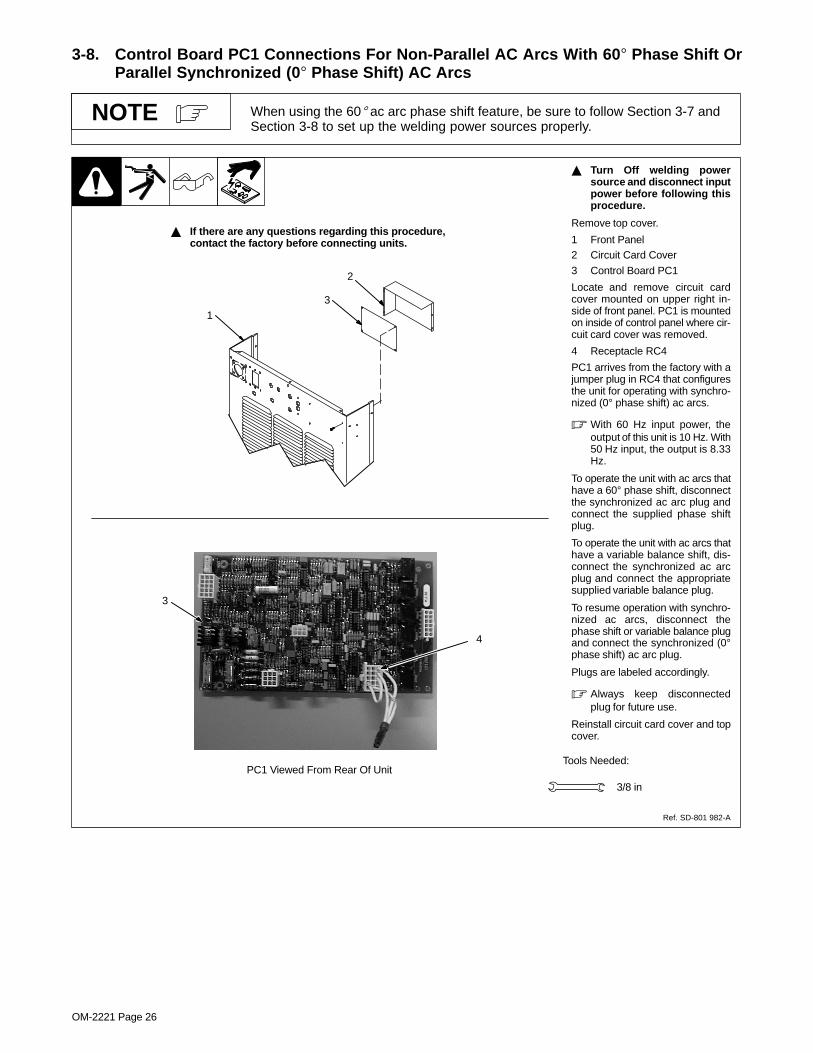
3-8. Control Board PC1 Connections For Non-Parallel AC Arcs With 60� Phase Shift OrParallel Synchronized (0� Phase Shift) AC Arcs
When using the 60� ac arc phase shift feature, be sure to follow Section 3-7 andSection 3-8 to set up the welding power sources properly.
NOTE
� Turn Off welding powersource and disconnect inputpower before following thisprocedure.
Remove top cover.
1 Front Panel2 Circuit Card Cover
3 Control Board PC1
Locate and remove circuit cardcover mounted on upper right in-side of front panel. PC1 is mountedon inside of control panel where cir-cuit card cover was removed.
4 Receptacle RC4
PC1 arrives from the factory with ajumper plug in RC4 that configuresthe unit for operating with synchro-nized (0° phase shift) ac arcs.
� With 60 Hz input power, theoutput of this unit is 10 Hz. With50 Hz input, the output is 8.33Hz.
To operate the unit with ac arcs thathave a 60° phase shift, disconnectthe synchronized ac arc plug andconnect the supplied phase shiftplug.
To operate the unit with ac arcs thathave a variable balance shift, dis-connect the synchronized ac arcplug and connect the appropriatesupplied variable balance plug.
To resume operation with synchro-nized ac arcs, disconnect thephase shift or variable balance plugand connect the synchronized (0°phase shift) ac arc plug.
Plugs are labeled accordingly.
� Always keep disconnectedplug for future use.
Reinstall circuit card cover and topcover.
� If there are any questions regarding this procedure, contact the factory before connecting units.
Tools Needed:
1
3/8 in
3
2
3
PC1 Viewed From Rear Of Unit
4
Ref. SD-801 982-A

OM-2221 Page 27
3-9. Testing AC Output Units For Correct Phasing Prior to Parallel Operation� Turn Off welding power
sources and disconnect in-put power before openingaccess door.
� If units are not phased cor-rectly, the welding powersources may be damaged.
� Open-circuit voltage will bepresent on all electrodesduring this check. If the ma-chines are not phased cor-rectly, the voltage betweenelectrodes may equal twotimes open-circuit voltage(135 - 145 volts ac). Have onlyqualified persons do thistesting.
Be sure synchronizing connectionsin Section 3-6 have been made be-fore performing this procedure.Make connections as shown in il-lustration. Connect ac voltmeterbetween electrode connected tofirst (master) unit and electrodeconnected to second (slave) unit.
Power On both units and place bothoutput control switches in On posi-tion. When the units are properlyphased, the voltmeter will readless than one volt ac.
If the meter reads more than onevolt ac, the unit’s primary lines arenot matched in the proper phasesequence (see Section 2-16).
After performing the test in Section2-16, retest the units for phasing.When the second (slave) unit is inphase with the first (master) unit,test phasing between third unit (ifapplicable) and second unit. Al-ways test and correct phasing be-tween following unit and the unitprevious to it (check fourth unitagainst third unit, fifth unit againstfourth unit, etc.).
After setting units up for correctsynchronizing, connect units ac-cording to section covering desiredmultiple unit use (see Sections 3-2,3-3, and 3-5).
To Work
To Separate Electrode(Electrically Isolated From
All Other Electrodes)
First (Master) UnitConnections
Second (Slave) Unit(And Following Units)
Connections
� If there are any questions regarding this procedure, contact the factory before connecting units.
To Separate Electrode(Electrically Isolated From
All Other Electrodes)
Set on AC Volts Scale
Meter Polarity Does Not Matter
To Work
ST-801 882-A
Shielded Cable To Terminal Strip TE4(See Section 3-6)
To Next AC Unit
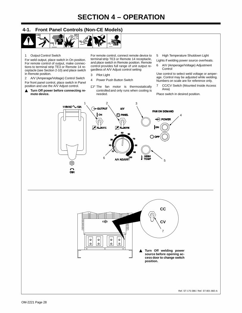
OM-2221 Page 28
SECTION 4 – OPERATION
4-1. Front Panel Controls (Non-CE Models)
1 Output Control SwitchFor weld output, place switch in On position.For remote control of output, make connec-tions to terminal strip TE3 or Remote 14 re-ceptacle (see Section 2-10) and place switchin Remote position.2 A/V (Amperage/Voltage) Control SwitchFor front panel control, place switch in Panelposition and use the A/V Adjust control.� Turn Off power before connecting re-
mote device.
For remote control, connect remote device toterminal strip TE3 or Remote 14 receptacle,and place switch in Remote position. Remotecontrol provides full range of unit output re-gardless of A/V Adjust control setting
3 Pilot Light
4 Power Push Button Switch
� The fan motor is thermostaticallycontrolled and only runs when cooling isneeded.
5 High Temperature Shutdown Light
Lights if welding power source overheats.
6 A/V (Amperage/Voltage) AdjustmentControl
Use control to select weld voltage or amper-age. Control may be adjusted while welding.Numbers on scale are for reference only.
7 CC/CV Switch (Mounted Inside AccessArea)
Place switch in desired position.
Ref. ST-175 086 / Ref. ST-801 882-A
1 2
4
6
� Turn Off welding powersource before opening ac-cess door to change switchposition.
3
5
CC
CV
7

OM-2221 Page 29
4-2. Front Panel Controls (CE Models)
1 Output Control SwitchFor weld output, place switch in On position.For remote control of output, make connec-tions to terminal strip TE3 or Remote 14 re-ceptacle (see Section 2-10) and place switchin Remote position.2 A/V (Amperage/Voltage) Control SwitchFor front panel control, place switch in Panelposition and use the A/V Adjust control.� Turn Off power before connecting re-
mote device.
For remote control, connect remote device toterminal strip TE3 or Remote 14 receptacle,and place switch in Remote position. Remotecontrol provides full range of unit output re-gardless of A/V Adjust control setting
3 Pilot Light
4 Power Push Button Switch
� The fan motor is thermostaticallycontrolled and only runs when cooling isneeded.
5 High Temperature Shutdown Light
Lights if welding power source overheats.
6 A/V (Amperage/Voltage) AdjustmentControl
Use control to select weld voltage or amper-age. Control may be adjusted while welding.Numbers on scale are for reference only.
7 CC/CV Switch (Mounted Inside AccessArea)
Place switch in desired position.
Ref. ST-175 086 / Ref. ST-801 882-A
1 2
4
6
� Turn Off welding powersource before opening ac-cess door to change switchposition.
3
5
CC
CV
7

OM-2221 Page 30
SECTION 5 – MAINTENANCE AND TROUBLESHOOTING
� Disconnect input power before maintaining.
� Maintain more oftenduring severe conditions.
5-1. Routine Maintenance
3 Months
Replace damagedor unreadablelabels.
Repair or replacecracked cables.
Replacecrackedtorch body.
Repair or replacecracked cables andcords.
Clean andtightenweld
terminals.
6 Months
Blow out inside.
5-2. Fuses F1 And F2
Ref. ST-801 883-B
� Turn Off welding powersource and disconnect inputpower before checking fuse.
Fuses F1 and F2 protect the 115volt ac winding of transformer T2. Iffuse F1 or F2 opens, the weldingpower source shuts down.
Remove top cover from unit to ac-cess fuses.
1 Fuse F1
Check F1 and replace if needed,using a fuse of the same rating.
2 Fuse F2
Check F2 and replace if needed,using a fuse of the same rating.
Use proper tool when removingfuses.
Reinstall top cover.
3/8 in
Tools Needed:
2
Rear of Unit
1

OM-2221 Page 31
5-3. Access Area Circuit Breakers� Turn Off welding power
source and disconnect inputpower before checking cir-cuit breakers.
1 Circuit Breaker CB2
CB2 protects the 24 VAC portion ofterminal strip TE3 and the Remote14 receptacle.
2 Circuit Breaker CB3
CB3 protects the 42 VAC portion ofterminal strip TE3.
Press button to reset breaker.
Ref. ST-175 086 / ST-801 882-A
1
2 ���
���
5-4. Troubleshooting
Trouble Remedy
No weld output; unit completely in-operative.
Place line disconnect switch in On position (see Section 2-15).
Check fuses F1 and F2 and replace if necessary (see Section 5-2).
Check and replace line fuse(s), if necessary, or reset circuit breaker (see Section 2-15).
Check for proper input power connections (see Section 2-15).
No weld output; pilot light On. Check, repair, or replace remote control.
Unit overheated. Allow unit to cool with fan On (see Section 2-2).
Have Factory Authorized Service Agent check control board PC1.
Erratic or improper weld output. Use proper size and type of weld cable (see Section 2-8).
Clean and tighten all weld connections.
Have Factory Authorized Service Agent check control board PC1.
No 115 volts ac output at duplexreceptacle, terminal strip TE3, and Re-mote 14 receptacle.
Reset circuit breaker CB1 (see Section 2-12).
No 230 volts ac output at duplex recep-tacle.
Reset circuit breaker CB4 (see Section 2-13).
No 24 volts ac output at terminal stripTE3 and Remote 14 receptacle.
Reset circuit breaker CB2 (see Section 5-3).
No 42 volts ac output at terminal stripTE3.
Reset circuit breaker CB3 (see Section 5-3).

OM-2221 Page 32
SECTION 6 – ELECTRICAL DIAGRAMS
193 775-A
Figure 6-1. Circuit Diagram For 460 And 575 VAC Input Models
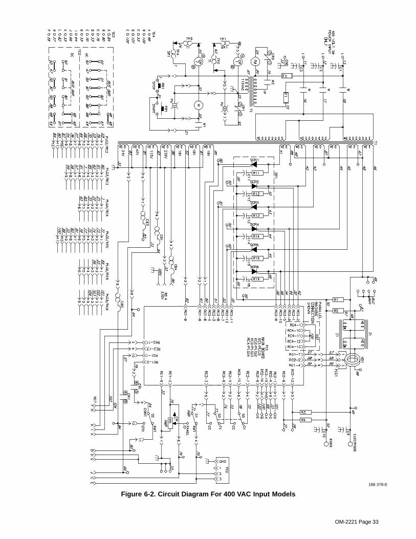
OM-2221 Page 33
188 378-E
Figure 6-2. Circuit Diagram For 400 VAC Input Models

OM-2221 Page 34
SECTION 7 – PARTS LIST
801 981-A
� Hardware is common andnot available unless listed.
1
2
34
5
69
10
11 12
13
14
15–(
Fig
. 7–3
)
16
17
1819
20
21
22
5
23
27
28
2927
30
241
31
(Fig
.7–2
) –3
2
2526
7 8
Figure 7-1. Main Assembly

OM-2221 Page 35
DescriptionPartNo.
Dia.Mkgs.
ItemNo.
Figure 7-1. Main Assembly
Quantity
1 071 624 PANEL, side 2. . . . . . . . . . . . . . . . . . . . . . . . . . . . . . . . . . . . . . . . . . . . . . . . . . . . . . . . . . . . . . . . . . . . . . 2 +070 555 COVER, top 1. . . . . . . . . . . . . . . . . . . . . . . . . . . . . . . . . . . . . . . . . . . . . . . . . . . . . . . . . . . . . . . . . . . . . . 3 134 327 LABEL, warning general precautionary 1. . . . . . . . . . . . . . . . . . . . . . . . . . . . . . . . . . . . . . . . . . . . . . . . 4 185 860 LABEL, warning electric shock 1. . . . . . . . . . . . . . . . . . . . . . . . . . . . . . . . . . . . . . . . . . . . . . . . . . . . . . . 5 184 340 CHANNEL, upright 4. . . . . . . . . . . . . . . . . . . . . . . . . . . . . . . . . . . . . . . . . . . . . . . . . . . . . . . . . . . . . . . . . 6 188 403 BRACKET, mtg lem 1. . . . . . . . . . . . . . . . . . . . . . . . . . . . . . . . . . . . . . . . . . . . . . . . . . . . . . . . . . . . . . . . 7 F1,F2 *012 639 FUSE, crtg 6A 600 V 2. . . . . . . . . . . . . . . . . . . . . . . . . . . . . . . . . . . . . . . . . . . . . . . . . . . . . . . 8 070 404 FUSE, holder 2. . . . . . . . . . . . . . . . . . . . . . . . . . . . . . . . . . . . . . . . . . . . . . . . . . . . . . . . . . . . . . . . . . . . . . 9 W 099 044 CONTACTOR, size 3-1/2 3P 1. . . . . . . . . . . . . . . . . . . . . . . . . . . . . . . . . . . . . . . . . . . . . . . . . . . .
W1,2 048 731 INTERLOCK, cntor No. size 3 2. . . . . . . . . . . . . . . . . . . . . . . . . . . . . . . . . . . . . . . . . . . . . . . . . . . . 10 C1-3 194 066 CAPACITOR 3. . . . . . . . . . . . . . . . . . . . . . . . . . . . . . . . . . . . . . . . . . . . . . . . . . . . . . . . . . . . . . . 11 184 349 BRACKET, mtg contactor 1. . . . . . . . . . . . . . . . . . . . . . . . . . . . . . . . . . . . . . . . . . . . . . . . . . . . . . . . . . 12 HD1 148 417 TRANSDUCER, current 1000A 1. . . . . . . . . . . . . . . . . . . . . . . . . . . . . . . . . . . . . . . . . . . . . . .
PLG1 130 204 CONNECTOR & SOCKET 1. . . . . . . . . . . . . . . . . . . . . . . . . . . . . . . . . . . . . . . . . . . . . . . . . . . . . . 13 TE2 187 739 TERMINAL ASSEMBLY, pwr output 1. . . . . . . . . . . . . . . . . . . . . . . . . . . . . . . . . . . . . . . . . . . . 14 184 359 BRACKET, mtg terminal assembly 2. . . . . . . . . . . . . . . . . . . . . . . . . . . . . . . . . . . . . . . . . . . . . . . . . . 15 Fig 7-3 REAR PANEL ASSEMBLY 1. . . . . . . . . . . . . . . . . . . . . . . . . . . . . . . . . . . . . . . . . . . . . . . . . . . . . . . . . . 16 185 856 LABEL, warning electric shock 1. . . . . . . . . . . . . . . . . . . . . . . . . . . . . . . . . . . . . . . . . . . . . . . . . . . . . . 17 Z1 184 350 STABILIZER 1. . . . . . . . . . . . . . . . . . . . . . . . . . . . . . . . . . . . . . . . . . . . . . . . . . . . . . . . . . . . . . . . . 18 T1 184 406 TRANSFORMER, pwr main (460 model) 1. . . . . . . . . . . . . . . . . . . . . . . . . . . . . . . . . . . . . . . . . 18 T1 188 222 TRANSFORMER, pwr main (575 model) 1. . . . . . . . . . . . . . . . . . . . . . . . . . . . . . . . . . . . . . . . . 18 T1 185 360 TRANSFORMER, pwr main (400 50/60hz model) 1. . . . . . . . . . . . . . . . . . . . . . . . . . . . . . . . .
TP2 163 266 THERMOSTAT, NC in trans. 150° C overload 1. . . . . . . . . . . . . . . . . . . . . . . . . . . . . . . . . . . . . . . . TP3 168 891 THERMOSTAT, NC in trans. 80° C fan on demand 1. . . . . . . . . . . . . . . . . . . . . . . . . . . . . . . . . . .
19 184 344 STOP, cover 1. . . . . . . . . . . . . . . . . . . . . . . . . . . . . . . . . . . . . . . . . . . . . . . . . . . . . . . . . . . . . . . . . . . . . 026 627 GASKET, lift eye 1. . . . . . . . . . . . . . . . . . . . . . . . . . . . . . . . . . . . . . . . . . . . . . . . . . . . . . . . . . . . . . . . . . . . . .
20 T2 094 237 TRANSFORMER, kva 1/2 115-230/460 (460 model) 1. . . . . . . . . . . . . . . . . . . . . . . . . . . . . . . 20 T2 096 145 TRANSFORMER, kva 1/2 115-230/575 (575 model) 1. . . . . . . . . . . . . . . . . . . . . . . . . . . . . . . 20 T2 185 359 TRANSFORMER, kva 1/2 115-220/400 (400 50/60hz model) 1. . . . . . . . . . . . . . . . . . . . . . . 21 184 342 LIFT, eye 1. . . . . . . . . . . . . . . . . . . . . . . . . . . . . . . . . . . . . . . . . . . . . . . . . . . . . . . . . . . . . . . . . . . . . . . . 22 184 341 BAR, cross lift eye 2. . . . . . . . . . . . . . . . . . . . . . . . . . . . . . . . . . . . . . . . . . . . . . . . . . . . . . . . . . . . . . . . 23 184 345 BRACKET, rectifier 1. . . . . . . . . . . . . . . . . . . . . . . . . . . . . . . . . . . . . . . . . . . . . . . . . . . . . . . . . . . . . . . . 24 SR1 184 357 RECTIFIER, scr main (consisting of) 1. . . . . . . . . . . . . . . . . . . . . . . . . . . . . . . . . . . . . . . . . . 25 026 947 STAND-OFF, insul .250-20 x 1.000 lg 3. . . . . . . . . . . . . . . . . . . . . . . . . . . . . . . . . . . . . . . . . . . . . . . 26 185 206 STRIP, mtg rectifier 2. . . . . . . . . . . . . . . . . . . . . . . . . . . . . . . . . . . . . . . . . . . . . . . . . . . . . . . . . . . . . . . 27 196 496 CLAMP, thyristor rectifier 4.750 6. . . . . . . . . . . . . . . . . . . . . . . . . . . . . . . . . . . . . . . . . . . . . . . . . . . . . 28 SCR1-6 148 091 THYRISTOR, scr 865 A 300 V 6. . . . . . . . . . . . . . . . . . . . . . . . . . . . . . . . . . . . . . . . . . . . 29 185 207 STRIP, spacing heat sink 3. . . . . . . . . . . . . . . . . . . . . . . . . . . . . . . . . . . . . . . . . . . . . . . . . . . . . . . . . .
082 852 BUS BAR, output rectifier 2. . . . . . . . . . . . . . . . . . . . . . . . . . . . . . . . . . . . . . . . . . . . . . . . . . . . . . . . . . . . . . 30 C11-16/. . .
R11-16 185 183 CAPACITOR/RESISTOR 6. . . . . . . . . . . . . . . . . . . . . . . . . . . . . . . . . . . . . . . . . . . . . . . . . . . . . . TP1 012 786 THERMOSTAT, NC open 165° F in SR1 overload 1. . . . . . . . . . . . . . . . . . . . . . . . . . . . . . . . . . . . TP4 168 894 THERMOSTAT, NC open 125° F in SR1 fan on demand 1. . . . . . . . . . . . . . . . . . . . . . . . . . . . . .
31 184 343 BASE 1. . . . . . . . . . . . . . . . . . . . . . . . . . . . . . . . . . . . . . . . . . . . . . . . . . . . . . . . . . . . . . . . . . . . . . . . . . . 32 Fig 7-2 FRONT PANEL ASSEMBLY 1. . . . . . . . . . . . . . . . . . . . . . . . . . . . . . . . . . . . . . . . . . . . . . . . . . . . . . . . .
+When ordering a component originally displaying a precautionary label, the label should also be ordered.*Recommended Spare Parts.To maintain the factory original performance of your equipment, use only Manufacturer’s SuggestedReplacement Parts. Model and serial number required when ordering parts from your local distributor.

OM-2221 Page 36
� Hardware is common andnot available unless listed.
SD-801 982-A
1
23
45
67
89
10
12
11 13
15
1617
18
14
23 24
25
26
27
528
2930
31
32
3334
35
36
37
19
2021
15
22
38
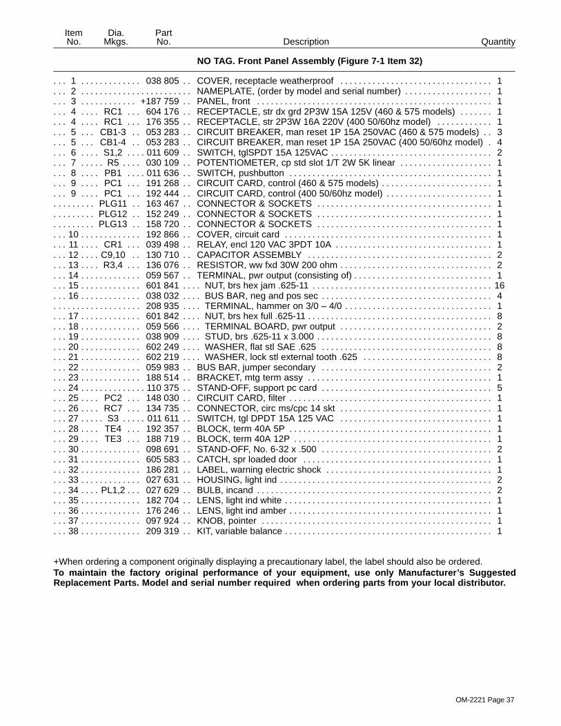
OM-2221 Page 37
DescriptionPartNo.
Dia.Mkgs.
ItemNo.
NO TAG. Front Panel Assembly (Figure 7-1 Item 32)
Quantity
1 038 805 COVER, receptacle weatherproof 1. . . . . . . . . . . . . . . . . . . . . . . . . . . . . . . . . . . . . . . . . . . . . . . . . . . 2 NAMEPLATE, (order by model and serial number) 1. . . . . . . . . . . . . . . . . . . . . . . . . . . . . . . . . . . . . . . . . . . . . . 3 +187 759 PANEL, front 1. . . . . . . . . . . . . . . . . . . . . . . . . . . . . . . . . . . . . . . . . . . . . . . . . . . . . . . . . . . . . . . . . . . . 4 RC1 604 176 RECEPTACLE, str dx grd 2P3W 15A 125V (460 & 575 models) 1. . . . . . . . . . . . . . . . . . . 4 RC1 176 355 RECEPTACLE, str 2P3W 16A 220V (400 50/60hz model) 1. . . . . . . . . . . . . . . . . . . . . . . . 5 CB1-3 053 283 CIRCUIT BREAKER, man reset 1P 15A 250VAC (460 & 575 models) 3. . . . . . . . . . . . 5 CB1-4 053 283 CIRCUIT BREAKER, man reset 1P 15A 250VAC (400 50/60hz model) 4. . . . . . . . . . . 6 S1,2 011 609 SWITCH, tglSPDT 15A 125VAC 2. . . . . . . . . . . . . . . . . . . . . . . . . . . . . . . . . . . . . . . . . . . . . . . . 7 R5 030 109 POTENTIOMETER, cp std slot 1/T 2W 5K linear 1. . . . . . . . . . . . . . . . . . . . . . . . . . . . . . . . . . 8 PB1 011 636 SWITCH, pushbutton 1. . . . . . . . . . . . . . . . . . . . . . . . . . . . . . . . . . . . . . . . . . . . . . . . . . . . . . . . . 9 PC1 191 268 CIRCUIT CARD, control (460 & 575 models) 1. . . . . . . . . . . . . . . . . . . . . . . . . . . . . . . . . . . . 9 PC1 192 444 CIRCUIT CARD, control (400 50/60hz model) 1. . . . . . . . . . . . . . . . . . . . . . . . . . . . . . . . . . .
PLG11 163 467 CONNECTOR & SOCKETS 1. . . . . . . . . . . . . . . . . . . . . . . . . . . . . . . . . . . . . . . . . . . . . . . . . . . PLG12 152 249 CONNECTOR & SOCKETS 1. . . . . . . . . . . . . . . . . . . . . . . . . . . . . . . . . . . . . . . . . . . . . . . . . . . PLG13 158 720 CONNECTOR & SOCKETS 1. . . . . . . . . . . . . . . . . . . . . . . . . . . . . . . . . . . . . . . . . . . . . . . . . . .
10 192 866 COVER, circuit card 1. . . . . . . . . . . . . . . . . . . . . . . . . . . . . . . . . . . . . . . . . . . . . . . . . . . . . . . . . . . . . . . 11 CR1 039 498 RELAY, encl 120 VAC 3PDT 10A 1. . . . . . . . . . . . . . . . . . . . . . . . . . . . . . . . . . . . . . . . . . . . . . 12 C9,10 130 710 CAPACITOR ASSEMBLY 2. . . . . . . . . . . . . . . . . . . . . . . . . . . . . . . . . . . . . . . . . . . . . . . . . . . 13 R3,4 136 076 RESISTOR, ww fxd 30W 200 ohm 2. . . . . . . . . . . . . . . . . . . . . . . . . . . . . . . . . . . . . . . . . . . . . 14 059 567 TERMINAL, pwr output (consisting of) 1. . . . . . . . . . . . . . . . . . . . . . . . . . . . . . . . . . . . . . . . . . . . . . . . 15 601 841 NUT, brs hex jam .625-11 16. . . . . . . . . . . . . . . . . . . . . . . . . . . . . . . . . . . . . . . . . . . . . . . . . . . . . . . . . . . 16 038 032 BUS BAR, neg and pos sec 4. . . . . . . . . . . . . . . . . . . . . . . . . . . . . . . . . . . . . . . . . . . . . . . . . . . . . . . . .
208 935 TERMINAL, hammer on 3/0 – 4/0 1. . . . . . . . . . . . . . . . . . . . . . . . . . . . . . . . . . . . . . . . . . . . . . . . . . . . . . . 17 601 842 NUT, brs hex full .625-11 8. . . . . . . . . . . . . . . . . . . . . . . . . . . . . . . . . . . . . . . . . . . . . . . . . . . . . . . . . . . . 18 059 566 TERMINAL BOARD, pwr output 2. . . . . . . . . . . . . . . . . . . . . . . . . . . . . . . . . . . . . . . . . . . . . . . . . . . . . 19 038 909 STUD, brs .625-11 x 3.000 8. . . . . . . . . . . . . . . . . . . . . . . . . . . . . . . . . . . . . . . . . . . . . . . . . . . . . . . . . . 20 602 249 WASHER, flat stl SAE .625 8. . . . . . . . . . . . . . . . . . . . . . . . . . . . . . . . . . . . . . . . . . . . . . . . . . . . . . . . . 21 602 219 WASHER, lock stl external tooth .625 8. . . . . . . . . . . . . . . . . . . . . . . . . . . . . . . . . . . . . . . . . . . . . . . . 22 059 983 BUS BAR, jumper secondary 2. . . . . . . . . . . . . . . . . . . . . . . . . . . . . . . . . . . . . . . . . . . . . . . . . . . . . . . 23 188 514 BRACKET, mtg term assy 1. . . . . . . . . . . . . . . . . . . . . . . . . . . . . . . . . . . . . . . . . . . . . . . . . . . . . . . . . . 24 110 375 STAND-OFF, support pc card 5. . . . . . . . . . . . . . . . . . . . . . . . . . . . . . . . . . . . . . . . . . . . . . . . . . . . . . . . 25 PC2 148 030 CIRCUIT CARD, filter 1. . . . . . . . . . . . . . . . . . . . . . . . . . . . . . . . . . . . . . . . . . . . . . . . . . . . . . . . 26 RC7 134 735 CONNECTOR, circ ms/cpc 14 skt 1. . . . . . . . . . . . . . . . . . . . . . . . . . . . . . . . . . . . . . . . . . . . . 27 S3 011 611 SWITCH, tgl DPDT 15A 125 VAC 1. . . . . . . . . . . . . . . . . . . . . . . . . . . . . . . . . . . . . . . . . . . . . . . . 28 TE4 192 357 BLOCK, term 40A 5P 1. . . . . . . . . . . . . . . . . . . . . . . . . . . . . . . . . . . . . . . . . . . . . . . . . . . . . . . . 29 TE3 188 719 BLOCK, term 40A 12P 1. . . . . . . . . . . . . . . . . . . . . . . . . . . . . . . . . . . . . . . . . . . . . . . . . . . . . . . 30 098 691 STAND-OFF, No. 6-32 x .500 2. . . . . . . . . . . . . . . . . . . . . . . . . . . . . . . . . . . . . . . . . . . . . . . . . . . . . . . 31 605 583 CATCH, spr loaded door 1. . . . . . . . . . . . . . . . . . . . . . . . . . . . . . . . . . . . . . . . . . . . . . . . . . . . . . . . . . . 32 186 281 LABEL, warning electric shock 1. . . . . . . . . . . . . . . . . . . . . . . . . . . . . . . . . . . . . . . . . . . . . . . . . . . . . . 33 027 631 HOUSING, light ind 2. . . . . . . . . . . . . . . . . . . . . . . . . . . . . . . . . . . . . . . . . . . . . . . . . . . . . . . . . . . . . . . . 34 PL1,2 027 629 BULB, incand 2. . . . . . . . . . . . . . . . . . . . . . . . . . . . . . . . . . . . . . . . . . . . . . . . . . . . . . . . . . . . . . . 35 182 704 LENS, light ind white 1. . . . . . . . . . . . . . . . . . . . . . . . . . . . . . . . . . . . . . . . . . . . . . . . . . . . . . . . . . . . . . . 36 176 246 LENS, light ind amber 1. . . . . . . . . . . . . . . . . . . . . . . . . . . . . . . . . . . . . . . . . . . . . . . . . . . . . . . . . . . . . . 37 097 924 KNOB, pointer 1. . . . . . . . . . . . . . . . . . . . . . . . . . . . . . . . . . . . . . . . . . . . . . . . . . . . . . . . . . . . . . . . . . . . 38 209 319 KIT, variable balance 1. . . . . . . . . . . . . . . . . . . . . . . . . . . . . . . . . . . . . . . . . . . . . . . . . . . . . . . . . . . . . . .
+When ordering a component originally displaying a precautionary label, the label should also be ordered.To maintain the factory original performance of your equipment, use only Manufacturer’s SuggestedReplacement Parts. Model and serial number required when ordering parts from your local distributor.

OM-2221 Page 38
DescriptionPartNo.
Dia.Mkgs.
ItemNo.
Figure 7-2. Rear Panel Assembly (Figure 7-1 Item 15)
Quantity
1 CR2 059 266 RELAY, encl 120 VAC DPDT 10A/120 VAC 1. . . . . . . . . . . . . . . . . . . . . . . . . . . . . . . . . . . . . 2 209 477 WINDTUNNEL, 20in 1. . . . . . . . . . . . . . . . . . . . . . . . . . . . . . . . . . . . . . . . . . . . . . . . . . . . . . . . . . . . . . . 3 R1,2 097 459 RESISTOR, ww fxd 375W 20 ohm 2. . . . . . . . . . . . . . . . . . . . . . . . . . . . . . . . . . . . . . . . . . . . . 4 032 616 BLADE, fan 20.000 3wg 21deg 1. . . . . . . . . . . . . . . . . . . . . . . . . . . . . . . . . . . . . . . . . . . . . . . . . . . . . . 5 +070 558 PANEL, rear 1. . . . . . . . . . . . . . . . . . . . . . . . . . . . . . . . . . . . . . . . . . . . . . . . . . . . . . . . . . . . . . . . . . . . . 6 183 167 CONNECTOR, clamp cable 2.000 1. . . . . . . . . . . . . . . . . . . . . . . . . . . . . . . . . . . . . . . . . . . . . . . . . . . 7 102 207 PLATE, adapter power cord 1. . . . . . . . . . . . . . . . . . . . . . . . . . . . . . . . . . . . . . . . . . . . . . . . . . . . . . . . . 8 FM 032 605 MOTOR, cap perm sp 1/4hp 230 VAC 1625rpm 1. . . . . . . . . . . . . . . . . . . . . . . . . . . . . . . . . . .
� Hardware is common andnot available unless listed.
1
2
34 5
7
8
6
SD-801 983
Figure 7-2. Rear Panel Assembly+When ordering a component originally displaying a precautionary label, the label should also be ordered.To maintain the factory original performance of your equipment, use only Manufacturer’s SuggestedReplacement Parts. Model and serial number required when ordering parts from your local distributor.

OM-2221 Page 39
Notes

OM-2221 Page 40
Notes


Warranty Questions?
Call1-800-4-A-MILLERfor your localMiller distributor.
miller_warr 6/02
Your distributor also givesyou ...
ServiceYou always get the fast,reliable response youneed. Most replacementparts can be in yourhands in 24 hours.
SupportNeed fast answers to thetough welding questions?Contact your distributor.The expertise of thedistributor and Miller isthere to help you, everystep of the way.
Effective January 1, 2002(Equipment with a serial number preface of “LC” or newer)This limited warranty supersedes all previous Miller warranties and is exclusive with no other
guarantees or warranties expressed or implied.
LIMITED WARRANTY – Subject to the terms and conditionsbelow, Miller Electric Mfg. Co., Appleton, Wisconsin, warrantsto its original retail purchaser that new Miller equipment soldafter the effective date of this limited warranty is free of defectsin material and workmanship at the time it is shipped by Miller.THIS WARRANTY IS EXPRESSLY IN LIEU OF ALL OTHERWARRANTIES, EXPRESS OR IMPLIED, INCLUDING THEWARRANTIES OF MERCHANTABILITY AND FITNESS.
Within the warranty periods listed below, Miller will repair orreplace any warranted parts or components that fail due tosuch defects in material or workmanship. Miller must benotified in writing within thirty (30) days of such defect orfailure, at which time Miller will provide instructions on thewarranty claim procedures to be followed.
Miller shall honor warranty claims on warranted equipmentlisted below in the event of such a failure within the warrantytime periods. All warranty time periods start on the date thatthe equipment was delivered to the original retail purchaser, orone year after the equipment is sent to a North Americandistributor or eighteen months after the equipment is sent to anInternational distributor.
1. 5 Years Parts — 3 Years Labor
* Original main power rectifiers* Inverters (input and output rectifiers only)
2. 3 Years — Parts and Labor
* Transformer/Rectifier Power Sources* Plasma Arc Cutting Power Sources* Semi-Automatic and Automatic Wire Feeders* Inverter Power Supplies* Intellitig* Engine Driven Welding Generators
(NOTE: Engines are warranted separately bythe engine manufacturer.)
3. 1 Year — Parts and Labor Unless Specified
* DS-2 Wire Feeder* Motor Driven Guns (w/exception of Spoolmate
Spoolguns)* Process Controllers* Positioners and Controllers* Automatic Motion Devices* RFCS Foot Controls* Induction Heating Power Sources* Water Coolant Systems* Flowgauge and Flowmeter Regulators (No Labor)* HF Units* Grids* Maxstar 85, 140* Spot Welders* Load Banks* Racks* Running Gear/Trailers* Plasma Cutting Torches (except APT & SAF
Models)* Field Options
(NOTE: Field options are covered under TrueBlue for the remaining warranty period of theproduct they are installed in, or for a minimum ofone year — whichever is greater.)
4. 6 Months — Batteries
5. 90 Days — Parts
* MIG Guns/TIG Torches* Induction Heating Coils and Blankets
* APT, ZIPCUT & PLAZCUT Model Plasma CuttingTorches
* Remote Controls* Accessory Kits
* Replacement Parts (No labor)* Spoolmate Spoolguns* Canvas Covers
Miller’s True Blue Limited Warranty shall not apply to:
1. Consumable components; such as contact tips,cutting nozzles, contactors, brushes, slip rings,relays or parts that fail due to normal wear.(Exception: brushes, slip rings, and relays arecovered on Bobcat, Trailblazer, and Legend models.)
2. Items furnished by Miller, but manufactured by others,such as engines or trade accessories. These items arecovered by the manufacturer’s warranty, if any.
3. Equipment that has been modified by any party otherthan Miller, or equipment that has been improperlyinstalled, improperly operated or misused based uponindustry standards, or equipment which has not hadreasonable and necessary maintenance, or equipmentwhich has been used for operation outside of thespecifications for the equipment.
MILLER PRODUCTS ARE INTENDED FOR PURCHASEAND USE BY COMMERCIAL/INDUSTRIAL USERS ANDPERSONS TRAINED AND EXPERIENCED IN THE USEAND MAINTENANCE OF WELDING EQUIPMENT.
In the event of a warranty claim covered by this warranty, theexclusive remedies shall be, at Miller’s option: (1) repair; or (2)replacement; or, where authorized in writing by Miller inappropriate cases, (3) the reasonable cost of repair orreplacement at an authorized Miller service station; or (4)payment of or credit for the purchase price (less reasonabledepreciation based upon actual use) upon return of the goodsat customer’s risk and expense. Miller’s option of repair orreplacement will be F.O.B., Factory at Appleton, Wisconsin, orF.O.B. at a Miller authorized service facility as determined byMiller. Therefore no compensation or reimbursement fortransportation costs of any kind will be allowed.
TO THE EXTENT PERMITTED BY LAW, THE REMEDIESPROVIDED HEREIN ARE THE SOLE AND EXCLUSIVEREMEDIES. IN NO EVENT SHALL MILLER BE LIABLE FORDIRECT, INDIRECT, SPECIAL, INCIDENTAL ORCONSEQUENTIAL DAMAGES (INCLUDING LOSS OFPROFIT), WHETHER BASED ON CONTRACT, TORT ORANY OTHER LEGAL THEORY.
ANY EXPRESS WARRANTY NOT PROVIDED HEREINAND ANY IMPLIED WARRANTY, GUARANTY ORREPRESENTATION AS TO PERFORMANCE, AND ANYREMEDY FOR BREACH OF CONTRACT TORT OR ANYOTHER LEGAL THEORY WHICH, BUT FOR THISPROVISION, MIGHT ARISE BY IMPLICATION,OPERATION OF LAW, CUSTOM OF TRADE OR COURSEOF DEALING, INCLUDING ANY IMPLIED WARRANTY OFMERCHANTABILITY OR FITNESS FOR PARTICULARPURPOSE, WITH RESPECT TO ANY AND ALLEQUIPMENT FURNISHED BY MILLER IS EXCLUDED ANDDISCLAIMED BY MILLER.
Some states in the U.S.A. do not allow limitations of how longan implied warranty lasts, or the exclusion of incidental,indirect, special or consequential damages, so the abovelimitation or exclusion may not apply to you. This warrantyprovides specific legal rights, and other rights may beavailable, but may vary from state to state.
In Canada, legislation in some provinces provides for certainadditional warranties or remedies other than as stated herein,and to the extent that they may not be waived, the limitationsand exclusions set out above may not apply. This LimitedWarranty provides specific legal rights, and other rights maybe available, but may vary from province to province.

PRINTED IN USA 2002 Miller Electric Mfg. Co. 1/02
Miller Electric Mfg. Co.An Illinois Tool Works Company1635 West Spencer StreetAppleton, WI 54914 USA
International Headquarters–USAUSA Phone: 920-735-4505 Auto-AttendedUSA & Canada FAX: 920-735-4134International FAX: 920-735-4125
European Headquarters –United KingdomPhone: 44 (0) 1204-593493FAX: 44 (0) 1204-598066
www.MillerWelds.com
Model Name Serial/Style Number
Purchase Date (Date which equipment was delivered to original customer.)
Distributor
Address
City
State Zip
Please complete and retain with your personal records.
Always provide Model Name and Serial/Style Number.
Call 1-800-4-A-Miller or see our website at www.MillerWelds.comto locate a DISTRIBUTOR or SERVICE AGENCY near you.
Welding Supplies and Consumables
Options and Accessories
Personal Safety Equipment
Service and Repair
Replacement Parts
Training (Schools, Videos, Books)
Technical Manuals (Servicing Informationand Parts)
Circuit Diagrams
Welding Process Handbooks
Contact the Delivering Carrier for:
For assistance in filing or settling claims,contact your distributor and/or equipmentmanufacturer’s Transportation Department.
For Service
Owner’s Record
File a claim for loss or damage duringshipment.
Contact your Distributor for: