summasign maintenance manual
DESCRIPTION
Summasign Vinyl Cutter Maintenance manualTRANSCRIPT

Service Manual
SummaSign Series
Summa NVRochesterlaan 6
8470 GistelBelgium
Service Manual SummaSign
TABLE OF CONTENTS......................................................................Page
SECTION 1 KEYBOARD CONTROL
1.1. THE CONTROL PANEL .......................................................................................1.1
1.1.1. THE LIQUID CRYSTAL DISPLAY ....................................................................1.3
1.1.2. THE RESET/LOAD KEY ..............................................................................1.3
1.1.3. THE ON LINE KEY ..........................................................................................1.4
1.1.4. THE MENU KEY ...............................................................................................1.4
1.1.5. THE ENTER KEY ..........................................................................................1.6
1.1.6. 2 THE 1 AND 2 KEYS ....................................................................................1.6
1.1.7.THE JOGGING KEYS ........................................................................................1.6
1.1.8. THE TOOL UP/DOWN KEY ..........................................................................1.6
1.1.9. THE TOOL SELECT KEY ................................................................................1.7
1.2. NORMAL OPERATION ........................................................................................1.8
1.2.1. ON LINE AND OFF LINE ..................................................................................1.8
1.2.2. LOCAL OPERATION ........................................................................................1.9
1.3. THE USER CONFIG MENU ...............................................................................1.10
1.3.1. KNIFE PRESSURE .........................................................................................1.12
1.3.2. PEN PRESSURE .............................................................................................1.12
1.3.3. POUNCING PRESSURE .................................................................................1.12
1.3.4. KNIFE OFFSET ...............................................................................................1.12
1.3.5. POUNCING GAP .............................................................................................1.13
Table of Contents TOC-i

SummaSign Service Manual
1.3.6. VELOCITY .......................................................................................................1.13
1.3.7. OVERCUT .......................................................................................................1.13
1.3.8. SYSTEM SETUP .............................................................................................1.13
1.4. SYSTEM SET UP ...............................................................................................1.14
1.4.1. CONCATENATION .........................................................................................1.14
1.4.2. SMOOTHING ...................................................................................................1.14
1.4.3. EMULATE .......................................................................................................1.14
1.4.4. TOOL ...............................................................................................................1.15
1.4.5. MENU UNITS ..................................................................................................1.15
1.4.6. ADDRESSING .................................................................................................1.15
1.4.7. BAUD RATE ....................................................................................................1.15
1.4.8. PARITY ............................................................................................................1.16
1.4.9. RTS/DTR .........................................................................................................1.16
1.4.10. DM/PL ERRORS ...........................................................................................1.17
1.4.11. HP/GL ERRORS ...........................................................................................1.17
1.4.12. HP/GL ORIGIN ..............................................................................................1.17
1.4.13. MEDIA SENSOR ...........................................................................................1.18
1.4.14. AUTOLOAD ..................................................................................................1.18
1.4.15. TOOL COMMAND .........................................................................................1.18
1.4.16. LOAD ON W COMMAND ..............................................................................1.18
1.4.17. FLEX-CUT .....................................................................................................1.19
TOC-ii Table of Contents

Service Manual SummaSign
1.4.18. RECUT OFFSET ...........................................................................................1.19
1.5. INTERNAL TEST MENU ....................................................................................1.20
1.5.1. TANG. KNIFE CALIBRATION ........................................................................1.21
1.5.2. ADJUST ORIGIN TEST ROUTINE .................................................................1.22
1.5.3. ADJUST LAT. TEST ROUTINE ......................................................................1.23
1.5.4. ADJUST LONG. TEST ROUTINE ...................................................................1.25
1.5.5. CUT BORDER .................................................................................................1.26
1.5.6. MENU PLOT ....................................................................................................1.26
1.5.7. CONFIDENCE CUT .........................................................................................1.27
1.5.8. DIN CUT ..........................................................................................................1.27
1.5.9. SYSTEM TESTS .............................................................................................1.27
1.6. SYSTEM TESTS ................................................................................................1.28
1.6.1. LANGUAGE ....................................................................................................1.28
1.6.2. ROM REVISION ..............................................................................................1.28
1.6.3. SERVICE PLOT ..............................................................................................1.28
1.6.4. SENSOR SETUP .............................................................................................1.29
1.6.5. CALIBRATION ................................................................................................1.29
1.6.6. TRACKING TEST ............................................................................................1.29
1.6.7. FRICTION PLOT .............................................................................................1.29
1.6.8. RS232 TEST ....................................................................................................1.29
1.6.9. RAM TEST ......................................................................................................1.30
Table of Contents TOC-iii
SummaSign Service Manual
1.6.10. INSTALL MENU ............................................................................................1.30
1.6.11. COIL SETUP .................................................................................................1.30
1.6.12. LCD CONTRAST ..........................................................................................1.30
SECTION 2 REPLACEMENT GUIDELINES
2.1. REMOVING THE LEFT-HAND COVER...................................................................3
2.2. REMOVING THE RIGHT-HAND COVER.................................................................3
2.3. REMOVING THE BOTTOM PLATE.........................................................................5
2.4. REPLACING THE CAMROLLERS..........................................................................5
2.5. REPLACING THE X-MOTOR IN THE 500, 610 AND THE OLD 750.....................7
2.6. REPLACING AN X-MOTOR IN THE MODELS 750/1010 AND 1300.....................9
2.7. REPLACING THE Y-MOTOR................................................................................11
2.8. REPLACING THE LCD OR THE KEYBOARD......................................................13
2.9. REPLACING THE MAIN PCB................................................................................15
2.10. REPLACING THE SMALL PCB ON THE MAIN PCB.........................................19
2.11. REPLACING A DRAG HEAD OR A TANGENTIAL HEAD.................................21
2.12. REPLACING THE FLAT CABLE FOR THE HEAD.............................................25
2.13. REPLACING THE Y-BELT..................................................................................29
2.14. REPLACING THE CUTTING STRIP....................................................................29
2.15. REPLACING THE SENSORS..............................................................................31
2.16. REPLACING THE FAN MOTOR..........................................................................31
2.17. REPLACING THE DRIVE DRUM.........................................................................33
TOC-iv Table of Contents
Service Manual SummaSign
SECTION 3 MAINTENANCE
3.1. CLEANING THE DRIVE SYSTEM........................................................................3.2
3.2. CLEANING THE SENSORS.................................................................................3.3
3.3. CLEANING THE NOSE PIECE.............................................................................3.4
3.4. OPERATING VOLTAGE CONVERSION..............................................................3.5
SECTION 4 CALIBRATION
4.1. MACHINE TYPE....................................................................................................4.2
4.2. MEDIA CALIBRATION.........................................................................................4.4
4.3. HEAD CALIBRATION...........................................................................................4.5
I. KNIFE CALIBRATION ( TANGENTIAL)...................................................................4.5
II. COIL CALIBRATION...............................................................................................4.5
4.5. OPOS CALIBRATION (OPTIONAL).....................................................................4.8
I. NORMAL CALIBRATION.........................................................................................4.8
II. FINE TUNING...........................................................................................................4.9
4.6. SENSOR TESTS.................................................................................................4.10
SECTION 5 ERROR CODES - TROUBLESHOOTING
5.1. MOTOR HOT.........................................................................................................5.2
5.2. ERROR IN X-AXIS................................................................................................5.2
5.3. ERROR IN Y-AXIS POSITION..............................................................................5.3
Table of Contents TOC-v
SummaSign Service Manual
5.4. LOW LINE VOLTAGE...........................................................................................5.3
5.5. HIGH LINE VOLTAGE..........................................................................................5.4
5.6. ILLEGAL PLOT COMMAND.................................................................................5.4
5.7. ILLEGAL CLIP & SCALE SETTINGS..................................................................5.4
5.8. SYNTAX ERROR..................................................................................................5.5
5.9. NVRAM FAILURES AND MESSAGES.................................................................5.5
5.10. RS232 ERROR....................................................................................................5.6
5.11. INTERNAL ERRORS..........................................................................................5.6
5.12. FLASHING ERRORS AND MESSAGES (ONLY ON NEW TYPE OF PCB)......5.7
5.13. ROM ERROR......................................................................................................5.7
5.14. RAM ERROR.......................................................................................................5.7
5.15. MACHINE UNABLE TO FIND THE KNIFE HOME POSITION...........................5.8
5.16. MARKERS NOT SENSED PROPERLY.............................................................5.8
SECTION 6 FIGURES
LEFT SIDE...................................................................................................................6-2
RIGHT SIDE (1)............................................................................................................6-3
KEYBOARD ASSY......................................................................................................6-4
RIGHT SIDE (2)............................................................................................................6-5
CUTTER CARRIAGE...................................................................................................6-6
TOC-vi Table of Contents

Service Manual SummaSign
T-HEAD........................................................................................................................6-7
D-HEAD........................................................................................................................6-8
BOTTOM......................................................................................................................6-9
REAR.........................................................................................................................6-10
MEDIA GUIDING SYSTEM........................................................................................6-11
MOTOR CONNECTIONS...........................................................................................6-12
CAMROLLER ASSY..................................................................................................6-13
SECTION 7 SPARE PARTS LIST
D500 SPARE PARTS..................................................................................................7-1
SUMMASIGN D610 SPARE PARTS...........................................................................7-2
SUMMASIGN D610 PRO SPARE PARTS..................................................................7-3
SUMMASIGN T610 SPARE PARTS...........................................................................7-4
SUMMASIGN T610 PRO SPARE PARTS...................................................................7-5
SUMMASIGN D750 SPARE PARTS...........................................................................7-6
SUMMASIGN D750 PRO SPARE PARTS..................................................................7-7
SUMMASIGN T750 SPARE PARTS...........................................................................7-8
SUMMASIGN T750 PRO SPARE PARTS...................................................................7-9
SUMMASIGN D1010 SPARE PARTS.......................................................................7-10
SUMMASIGN D1010 PRO SPARE PARTS..............................................................7-11
SUMMASIGN T1010 SPARE PARTS.......................................................................7-12
Table of Contents TOC-vii
SummaSign Service Manual
SUMMASIGN T1010 PLUS SPARE..........................................................................7-13
SUMMASIGN T1010 PRO SPARE............................................................................7-14
SUMMASIGN D1300 SPARE PARTS.......................................................................7-15
SUMMASIGN D1300 PRO SPARE PARTS..............................................................7-16
SUMMASIGN T1300 SPARE PARTS.......................................................................7-17
SUMMASIGN T1300 PRO SPARE PARTS...............................................................7-18
Appendix A removal of the left side
Appendix B procedure to flash from internal ROM’s
Appendix C procedure to set the pinch roller play
Appendix D procedure to change the motor on a T-head
TOC-viii Table of Contents
INTRODUCTION
1. OVERVIEW
This is the Summa Service Manual for the SummaSign series cutters. It providesinformation for servicing the cutters. All repairs are to be made by, or under thedirection of, authorised Summa service personnel.
This manual is copyrighted by Summa 1999. Summa reserves the right to change anyinformation contained in this manual without prior notice. Unauthorised copying,modification, distribution, or display is prohibited. All rights reserved.
2. MANUAL ORGANIZATION
This manual is divided into the following sections:
Table of Contents
Introduction
Keyboard controls
General replacement guidelines
Maintenance
Calibration
Troubleshooting
Figures - part numbers
List recommended spare parts
Keyboard control contains the following:
INTRODUCTION I-1

SummaSign Service Manual
This part contains an overview of the various tests and configurations that can beaccessed via the keyboard.
General replacement guidelines contains the following:
An overview of the removal and the replacement of various parts of the unit in the formof separate chapters. It is advisable to carefully read the procedure described in eachof the chapters prior to removing or replacing a particular part. In addition tostraightforward step by step procedures you will often find Notes and Cautions. Makesure you read these remarks as they will often facilitate re-installation and avoidmalfunctioning.
Maintenance contains the following:
An overview of the maintenance of various parts of the unit. It is advisable to carefullyread the procedure described in each of the chapters prior to removing or replacing aparticular part. You will often find Notes and Cautions. Make sure you read theseremarks as they will often avoid malfunctioning.
Calibration:
An overview of all the possible calibrations of the unit. Each time the machine isserviced check this section to see if any recalibration needs to be done.
Troubleshooting:
An overview of all the possible error messages that could appear on the LCD screen,and the possible solutions
Figures - part numbers:
Detailed figures of the various parts and assemblies of the machine.
Spare parts list
An overview of all the recommended spare parts. Normally only the parts figuring onthis list will be provided by Summa.
I-2 Introduction

Service Manual SummaSign
3. QUICK TOUR AROUND THE MACHINE
In order to get acquainted with your SummaSign Pro cutter, read the followingdescription of the rear panel components. Figure 1-1 shows the location of the maincomponents.
1. RS-232-C Port : - This DB-9P connector provides the communication linkbetween the cutter and a host computer. It allows bidirectional communicationbetween the host computer and the cutter.
Introduction I-3

SummaSign Service Manual
2. Parallel Port : - This 36-pin Centronics connector provides a unidirectionalcommunication link between the cutter and a host computer. The cutter canreceive but not transmit data via this port.
Note : only one interface can be active at any one time.The first port that receives data will be the active interface until the cutter is reset.
3. Power ON/OFF switch : - This rocker switch sets the cutter’s power to ON orOFF. To switch the power ON, press the “I” side of the rocker switch. To switchthe power OFF, press the “O” side of the rocker switch.
4. Power Entry Module : - The fuse box, the voltage select board and the AC powercord receptacle are located in the power entry module. The power-up procedure is explained in detail in Section 1.6. For information about the conversion of the cutter's operating voltage, seeSection 3.2.
5. Roll Media Guide Bushes : - The two guide bushes serve to keep the media rollin place when media is pulled from the roll.
6. Media Flanges : - The media flanges ensure proper routing of the media roll.
7. Media Support Roller : - Rotating support rollers for the media roll.
I-4 Introduction
Service Manual SummaSign
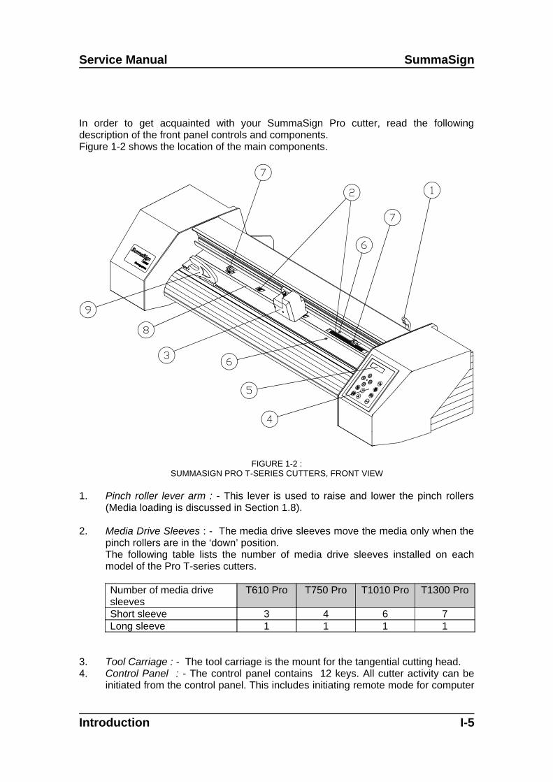
In order to get acquainted with your SummaSign Pro cutter, read the followingdescription of the front panel controls and components. Figure 1-2 shows the location of the main components.
FIGURE 1-2 :SUMMASIGN PRO T-SERIES CUTTERS, FRONT VIEW
1. Pinch roller lever arm : - This lever is used to raise and lower the pinch rollers(Media loading is discussed in Section 1.8).
2. Media Drive Sleeves : - The media drive sleeves move the media only when thepinch rollers are in the ‘down’ position.The following table lists the number of media drive sleeves installed on eachmodel of the Pro T-series cutters.
Number of media drivesleeves
T610 Pro T750 Pro T1010 Pro T1300 Pro
Short sleeve 3 4 6 7Long sleeve 1 1 1 1
3. Tool Carriage : - The tool carriage is the mount for the tangential cutting head.4. Control Panel : - The control panel contains 12 keys. All cutter activity can be
initiated from the control panel. This includes initiating remote mode for computer
Introduction I-5
SummaSign Service Manual
control, local mode for manual operation and menu mode. Each control panelfunction is explained in Section 2.1.
5. Display : - The 2x16 character display informs the user about the current statusof the cutting process or actions which need to be taken.
6. Sensors : - The sensors detect the presence of media to avoid any damage tothe cutting strip. Upon powering up the machine, they cause the media to moveall the way to the front edge of the platen.
7. Pinch rollers : - The pinch rollers (one at each side) hold the media clampedbetween the rubber rollers and the media drive sleeves.The T1010 and T1300 units are provided with an extra low pressure roller in themiddle to keep the vinyl media flat.
8. Cutting strip : - Soft strip to avoid any damage to the knife tip when no media hasbeen loaded. Since cutting is done on the cutting strip it is essential that thecutting strip remains intact.
9. Manual cut-off knife : - Upon completing a sign, move the media forward bypressing the key. Use the manual knife to cut the finished sign off the mediaroll. Leave the loaded media in place ready to start your next cut by pressing the
key again.
10. Stand : - The stand comes standard with the T1010 and T1300 units. For theT610 and T750 units the stand is optional.
I-6 Introduction

Keyboardcontrols 1-1
SECTION 1
KEYBOARD CONTROLS
THE CONTROL PANEL
The figure below shows the control panel of the SummaSign series cutters. The mainfunctions of the liquid crystal display (LCD) and the control panel keys are explained inthe following paragraphs. The explanation has been written for a T-series cutter. The only difference with the D-series is that some menu and configuration points have been omitted. The D-seriescutters work the same as T-series cutters when a drag knife is installed.
Keyboardcontrols 1-1

SummaSign series Cutters Service Manual
THE LIQUID CRYSTAL DISPLAY
The 32-character liquid crystal display (LCD) contains two lines of 16 characters each.The LCD provides cutter status information during operations and displays menuoptions for the configuration of the cutter.
The contrast of the LCD can be adjusted from the control panel in order to ensureoptimum readability under varying lighting conditions.Instructions for adjusting the LCD contrast are given in Section 1.6.12.
The various menu and submenu items are always presented in a loop, which meansthat, when the last menu or submenu item is displayed, pressing the appropriate keywill automatically take you back to the first item of the same menu or submenu.
Next to the status messages and/or menu options displayed on the LCD, arrow
symbols representing the , , , jogging keys and key will tellyou what keys to press to go to the next menu item (top line of the display) or to thenext value for a given submenu item (bottom line of the display).
THE RESET/LOAD KEY
The key (RESET/LOAD) is used to move the origin, to initiate a load sequence, to
reset the cutter, to abort the cut in progress or to recut the last file. When the key(RESET/LOAD) is pressed, the cutter goes off line, suspends all operations inprogress and displays the RESET/LOAD menu. Press the key until SET ORIGIN,LOAD, RESET, ABORT or RECUT is displayed. To confirm RESET, ABORT orRECUT press the key (ENTER). To execute the SET ORIGIN instruction move
the knife origin using the , , , jogging keys and press the key (ENTER)to confirm the new origin position. To initiate the LOAD instruction press the 1 or 2 keyto initiate a load sequence for a ROLL or SHEET respectively. Upon termination of anyof these instructions, the cutter goes on line again.
The SET ORIGIN instruction is used to move the knife origin.The LOAD instruction is used to initiate a load sequence. The RESET instruction performs a complete reset of the cutter. The ABORT instruction simply cancels the cut in progress. Aborting a cut will not resetthe cutter parameters: the parameters which had been selected for the cut remain ineffect.The RECUT instruction recuts the last file sent to the cutter (provided that it fitted intothe buffer).When using the multiple recut function the different copies will be cut in the media insuch a way that there is only a minimal loss of media. The distance between the copiescan be changed (See Section 1.4.18).
THE ON LINE KEY
1-2 Keyboardcontrols
Service Manual SummaSign series Cutters
The key (ON LINE) toggles between on line and off line operation. When the keyis pressed, the selected mode (ON LINE or OFF LINE) is displayed on the LCD.
Selecting OFF LINE will suspend all operations in progress. Pressing the key whilethe cutter is off line will make the cutter go on line again, resuming the suspendedoperation.
While the cutter is off line, the following operations can be performed:
Press the or jogging key to move the tool carriage to the left or right.
Press the or jogging key to make the media move forward (towards you)or backward (away from you). Moving the media forward will prove to be verypractical when you require to cut the finished sign off manually.
Press the key (TOOL UP/DOWN) to lower or raise the active tool. If the toolis not moved for approximately eight seconds, it is raised automatically.
The MENU Key
The key (MENU) is used to select one of the menus. Pressing the key will make
the cutter go off line and suspend all operations in progress. Pressing the keyrepeatedly will display the different menus one by one. As the menu options are on aloop, pressing the key when the last option is displayed will automatically returnyou to the first option.
Keyboardcontrols 1-3

SummaSign series Cutters Service Manual
ONLINE 1
Menu
800mm/ s 120g K
USER CONFIG 1
INTERNAL TESTS
SUMMASIGN SERIES CONFIGURATION SUBMENUS
To select a menu by scrolling through the different options, press the jogging key .
To exit from the menus and resume the previous on line operation, press the key(ON LINE).
Under normal conditions, the cutter is on line; it may then be selected by the hostcomputer for a cutting or plotting operation or deselected by the host computer.
Pressing the , or key will make the cutter go off line, in order to initiateanother operation.
1-4 Keyboardcontrols
Service Manual SummaSign series Cutters
MENU DESCRIPTION
USER CONFIG 1 (->4) Selects a given active cutter configuration from one of thefour sets of configuration parameters stored in the unit'smemory
INTERNAL TEST Activates one of the resident cutting plots provided forinformational purposes.
CONTENTS OF THE SUMMASIGN PRO T-SERIES MENUS
THE ENTER KEY
The key (ENTER) is used to select the item currently displayed on the LCD.
2 THE 1 AND 2 KEYS
The use of the 1 and 2 keys varies according to the operation in progress; their use isdisplayed on the LCD as appropriate.
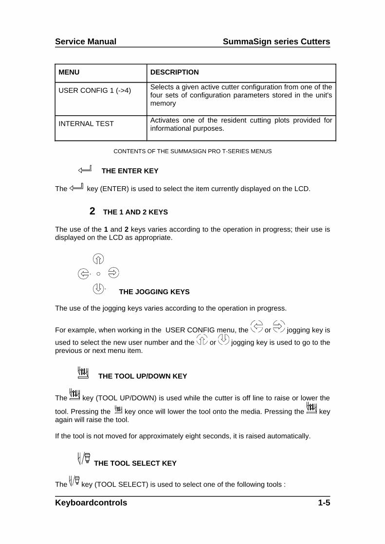
THE JOGGING KEYS
The use of the jogging keys varies according to the operation in progress.
For example, when working in the USER CONFIG menu, the or jogging key is
used to select the new user number and the or jogging key is used to go to theprevious or next menu item.
THE TOOL UP/DOWN KEY
The key (TOOL UP/DOWN) is used while the cutter is off line to raise or lower the
tool. Pressing the key once will lower the tool onto the media. Pressing the keyagain will raise the tool.
If the tool is not moved for approximately eight seconds, it is raised automatically.
THE TOOL SELECT KEY
The key (TOOL SELECT) is used to select one of the following tools :
Keyboardcontrols 1-5

SummaSign series Cutters Service Manual
a tangential knifea drag knifea ballpoint pen
To temporarily change the tool, press the key, then press the or joggingkey until the desired tool appears on the second line o the LCD. Press the key toconfirm the tool. An asterisk * appears next to the selected tool. When the cutter ispowered on the next time, the default tool will be selected. For setting up the defaulttool see Section 1.4.5.
1-6 Keyboardcontrols

Service Manual SummaSign series Cutters
NORMAL OPERATION
The term "normal operation" covers on line operation, off line operation and localoperation, i.e. the three types of operation for actual cutting or plotting. They areexplained in further detail in the following paragraphs.
ON LINE AND OFF LINE
On line and off line are two important concepts when using the SummaSign cutters.The cutter is on line only when the following message is displayed on the LCD :
800mm/s 120 g K.45mm(1) ON LINE 1
This display message should be read as follows :
800 mm/s = velocity120 g = knife pressure or pen pressureK = knife operation (K) or pen operation (P) or pouncing
operation.45 mm(1) = knife offset - only displayed when in drag knife modeON LINE = cutter is ready to receive data1 = user number
In all other cases, the cutter is off line.
When on line, the cutter can be addressed by the host computer, which means that thecutter will execute cutting or plotting instructions issued by the host computer'sapplication software. The host computer will first issue a SELECT sequence to the online cutter, and the message "*ON LINE" will be displayed on the LCD. The asteriskindicates that the host is in communication with the cutter : i.e. the cutter is now“selected” by the computer.When the cutter is on line and ready to receive instructions from the host computer, itwill remain deselected until actual instructions from the computer are received. Whenthe cutter is on line, but has not been selected by the host computer, the message "ONLINE" is displayed on the LCD, without the asterisk.
For normal cutting operations, the cutter MUST be on line, so that it can receiveinstructions from the host computer and the cutting/plotting software.
Keyboardcontrols 1-7

SummaSign series Cutters Service Manual
When the cutter is on line, but has not been selected by the host computer, thefollowing conditions must be met:
The cutter must be powered ON.
Media must be loaded. For detailed media loading instructions, see user’smanual .
The proper tool must be installed.
The cutter must be connected to the host computer via a RS-232-C link or aparallel interface.
The cutter must be configured for the scheduled operation.
To put the cutter off line, press the , or key. Pressing any of these keys willsuspend the current cutting/plotting operation until the cutter is put on line again.
LOCAL OPERATION
Local operation is only possible while the cutter is off line. Local operation means thatthe cutter is operated directly by the operator via instructions entered on the controlpanel.
To work in local operation mode, proceed as follows:
1. If the cutter is still on line, press the key once to select off line. The media willmove forward over a certain distance.
2. To move the carriage to the left or right, press the or jogging key.
3. To make the media move forwards (towards you) or backwards (away from you),
press the or jogging key.
4. To move the tool head up or down, press the key.
5. To end local mode and put the cutter on line again, press the key.
1-8 Keyboardcontrols

Service Manual SummaSign series Cutters
THE USER CONFIG MENU
The USER CONFIG(uration) menu gives access to different submenus which allow youto configure the cutter's operating parameters. It should be taken into account thataccess to some of the submenus will be determined by the plotting language you areusing.
Four different user configurations can be saved. The selected configuration number isdisplayed on the LCD next to the USER CONFIG message. These four USER CONFIG1(->4) menus are maintained independently.
To select another configuration number, proceed as follows:
1. Power on the cutter.
2. Press the key until USER CONFIG 1(->4) is displayed.
3. Press the or jogging key until the desired configuration number is dis-played next to USER CONFIG.
NOTE
Before altering any of the items in the USER CONFIG menu, make surethat you have previously selected the right configuration number in theUSER CONFIG 1(->4) menu.
To select and alter a configuration parameter, proceed as follows:
1. Power on the cutter.
2. Press the key until USER CONFIG 1(->4) is displayed.
3. Press the or jogging key until the desired submenu is displayed on thefirst line of the LCD.
4. Press the or jogging key until the desired value is displayed on thesecond line.
5. Press the key to confirm the selection, an * will be displayed next to theselected setting. (An * is always displayed next to the active value. )
Keyboardcontrols 1-9

SummaSign series Cutters Service Manual
* = IN DM/PL ONLY** = IN HP/GL AND HP/GL/2 ONLY
FLOWCHART SHOWING FACTORY PRESET MENU SETTINGS
1-10 Keyboardcontrols

Service Manual SummaSign series Cutters
KNIFE PRESSURE
The KNIFE PRESSURE submenu is used to set or modify the cutting pressure of theknife.
The default knife pressure value is 120 grams.The knife pressure can be set between 0 and 600 (400) grams.The knife pressure value is set in 5 gram increments.On the LCD, the active knife pressure value is marked with an *.
PEN PRESSURE
The PEN PRESSURE submenu is used to set or modify the pressure of the pen.The default pen pressure value is 80 grams (40grs).The pressure can be set between 0 and 600 (400) grams in 5 gram increments.On the LCD, the active pen pressure value is marked with an *.
POUNCING PRESSURE
The POUNCING PRESSURE submenu is used to set or modify the pressure of thepouncing tool.
The default pouncing pressure value is 120 grams.The pressure can be set between 0 and 600 grams in 5 gram increments.On the LCD, the active pouncing pressure value is marked with an *.
KNIFE OFFSET
The KNIFE OFFSET submenu is used to set or modify the distance between theDRAG knife blade tip and the centre axis. This routine applies to a drag knife only.
The default drag knife offset value is .45 mm.The value can be set between 0 and 1 mm.Make sure that the selected knife offset value matches that of the knife. Some finetuning may be necessary because of the mechanical tolerances on the knife. To verifythe knife offset, a test can be cut by pressing the 1 key.If the offset value is set too low, the rectangles will not close. When the offset value is set too high, the rectangles will be distorted.The offset test is illustrated below.
Keyboardcontrols 1-11

SummaSign series Cutters Service Manual
POUNCING GAP
The pouncing gap submenu is used to set or modify the distance between the pouncedwholes. This routine applies to the pouncer only.
The default pouncing gap value is 0 mm.The value can be set between o and 50 mm.On the LCD, the active pouncing gap value is marked with an *.
VELOCITY
The VELOCITY submenu is used to set or modify the velocity of the tool.The default velocity is 800 mm/s (32 ips).The velocity can be set between 50 mm/s (2 ips) and 1000 mm/s (40 ips).
OVERCUT
The OVERCUT submenu enables you to generate an overcut in order to facilitateweeding the cut.
The default overcut is set to 1.The overcut setting can be disabled (=0) or set to any value between 0(=off) and 10.One unit is about 0.1 mm or 0.004 ".On the LCD, the active value is marked with an *.
SYSTEM SETUP
The SYSTEM SETUP submenu covers the menu items you normally only need whenestablishing the initial setup e.g. when you install the cutter in combination with thesoftware you use.Press the key to access the different submenu items, which are explained insection 1.4.
1-12 Keyboardcontrols
Service Manual SummaSign series Cutters
SYSTEM SET UP
CONCATENATION
The CONCATENATION feature increases the speed and quality with which cut datahaving a very high resolution is cut. However when changing over to normal charactersagain, deactivate concatenation by setting this parameter to 0.On the LCD, the active concatenation value is marked with an *.
SMOOTHING
The SMOOTHING feature helps to cut smoother curves when curve data with manyshort vectors is received from the computer.The default setting is OFF.On the LCD, the active setting is marked with an *.
EMULATE
The EMULATE submenu is used to select the active cutting/plotting language for thecutter. The SummaSign Pro cutters support DM/PL , HP/GL and HP/GL/2.On the LCD, the active plotting language setting is marked with an *.
NOTE
The active cutting/plotting language MUST match the cutting software.
Always select a language which is supported by the host computer's cuttingsoftware.
Whenever possible, select the DM/PL menu option to set the active cutting/plottinglanguage to Houston Instrument Digital Microprocessor/Plotting Language (DM/PL).This selection will allow the cutter to operate with DM/PL-based cutting / plottingsoftware. This language, having special command extensions for cutting, normallygives superior cutting performance.
Select the HP/GL menu option to set the active cutting/plotting language to HP/GL. Thecutter will emulate an HP model 758xB plotter (with selectable origin, see 1.4.12).
TOOL
The TOOL submenu is used to select the default tool at power up.To configure the cutter for TANGENTIAL KNIFE cutting operations, select the TANG.KNIFE option.
Keyboardcontrols 1-13

SummaSign series Cutters Service Manual
To configure the cutter for PLOTTING operations, select the BALL POINT option.To configure the cutter for DRAG KNIFE cutting operations, select the DRAG KNIFEoption.To configure the cutter for POUNCING operations, select the POUNCING TOOLoption.To select a tool other than the default one temporarily, see section 1.1.9.
MENU UNITS
The MENU UNITS submenu allows you to select English or metric menu units forDM/PL. In HP/GL & HP/GL/2 the menu units are always in metric.
For models sold in the US, English units are the default setting.For models sold in Europe, metric units are the default setting.On the LCD, the active menu units setting is marked with an *.
ADDRESSING
The ADDRESSING submenu is used to select the cutter's default DM/PL user-addressable resolution. In HP/GL & HP/GL/2 the addressing is fixed at 0.025 mm.The default addressing resolution is 0.025 mm (Europe) or 0.001" (US).The user-addressable resolution can be set to 0.025 mm or 0.001" or 0.1 mm or0.005".On the LCD, the active resolution value is marked with an *
BAUD RATE
The BAUD RATE submenu is used to set or modify the operating baud rate for RS-232-C serial communications between your cutter and the host computer.
The default baud rate is 9600 bps.The baud rate can be set to any of the following values: 2400 bps, 4800 bps, 9600 bps,19200 and 38400 bps.On the LCD, the active baud rate value is marked with an *.
NOTEThe baud rate setting of your cutter MUST match the host computer's baudrate setting.
PARITY
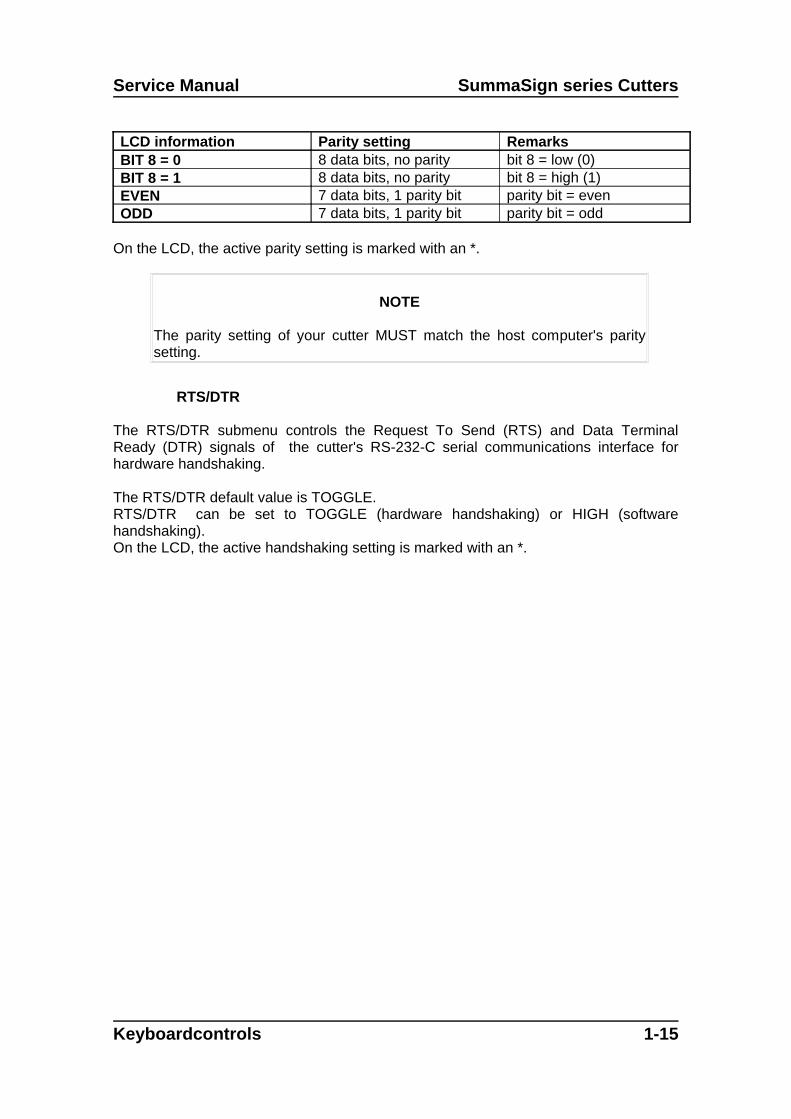
The PARITY submenu is used to set or modify the byte format and parity type for RS-232-C serial communications between your cutter and the host computer.
The default parity setting is bit 8 = 0 (8 data bits, no parity, the 8th bit being a low bit).The parity can be set to any of the following values:
1-14 Keyboardcontrols
Service Manual SummaSign series Cutters
LCD information Parity setting RemarksBIT 8 = 0 8 data bits, no parity bit 8 = low (0)BIT 8 = 1 8 data bits, no parity bit 8 = high (1)EVEN 7 data bits, 1 parity bit parity bit = evenODD 7 data bits, 1 parity bit parity bit = odd
On the LCD, the active parity setting is marked with an *.
NOTE
The parity setting of your cutter MUST match the host computer's paritysetting.
RTS/DTR
The RTS/DTR submenu controls the Request To Send (RTS) and Data TerminalReady (DTR) signals of the cutter's RS-232-C serial communications interface forhardware handshaking.
The RTS/DTR default value is TOGGLE.RTS/DTR can be set to TOGGLE (hardware handshaking) or HIGH (softwarehandshaking).On the LCD, the active handshaking setting is marked with an *.
Keyboardcontrols 1-15
SummaSign series Cutters Service Manual
DM/PL ERRORS
The DM/PL ERRORS submenu is used to determine whether or not different DM/PLerrors, such as illegal plot commands, invalid parameter ranges or communicationerrors, will be displayed on the LCD. This menu will only be displayed ifPLOT LANGUAGE is set to DM/PL.
The DM/PL ERRORS submenu can be set to REPORTED or IGNORED.On the LCD, the active setting is marked with an *.The feature is activated by selecting REPORTED. It is normally used only whenattempting to debug a communication link between the cutter and the host computer. After the communication link has been debugged, select IGNORED to disable thefeature.
HP/GL ERRORS
The HP/GL ERRORS submenu is used to determine whether or not different HP/GLerrors, such as illegal plot commands, invalid parameter ranges or communicationerrors, will be displayed on the LCD. This menu will only be displayed ifPLOT LANGUAGE is set to HP/GL.
The HP/GL ERRORS submenu can be set to REPORTED or IGNORED.On the LCD, the active setting is marked with an *.The feature is activated by selecting REPORTED. It is normally used only whenattempting to debug a communication link between the cutter and the host computer. After the communication link has been debugged, select IGNORED to disable thefeature.
HP/GL ORIGIN
The HP/GL ORIGIN submenu will only be displayed if the PLOT LANGUAGE is set toHP/GL. (See Paragraph 1.4.4.) The HP/GL ORIGIN submenu is used to set the originin the centre (see HP/GL 758x) or the bottom-right corner (see HP/GL 7475) of theloaded media.
The HP/GL ORIGIN option can be set to RIGHT_FRONT or CENTRE.On the LCD, the active setting is marked with an *.If the cut is found to be incomplete, and is wholly located in the upper left corner of themedia then modify the HP/GL ORIGIN setting to RIGHT FRONT. If the cut is found tobe incomplete, and is wholly located in the lower right corner of the media then changethe HP/GL ORIGIN setting to CENTRE.
1-16 Keyboardcontrols

Service Manual SummaSign series Cutters
MEDIA SENSOR
The MEDIA SENSOR submenu is used to activate or deactivate the media sensors.On the LCD, the active setting is marked with an *.The sensors detect whether media is loaded or detect the end of media. The sensorsprevent damage to the cutting strip and knife tip.
AUTOLOAD
The AUTOLOAD option enables the user to the change the vinyl unroll proceedings.When AUTOLOAD is ON , the cutter will automatically unroll the vinyl when needed.When the AUTOLOAD option is OFF, the operator himself should unroll enough mediabefore starting to cut.The default setting is ON. The best results and performance are guaranteed whenusing this setting. On the LCD display, the active setting is marked with an *.
TOOL COMMAND
The TOOL COMMAND is used to determine whether the DM/PL and HP/GL pen/knife-select commands (the P and SP commands respectively) are ignored or accepted. When the TOOL COMMAND option is set to “ACCEPT”, the P or SP commands willchange the selected tool in the cutter according to the suffix that follows the pen/knifecommand. The cutter’s LCD will, e.g. prompt the user with the following message:“INSERT PEN” when a P2 command is sent. When the TOOL COMMAND option is setto “IGNORE”, the pen/knife commands are ignored. On the LCD, the active setting is marked with an *. The default setting is “ACCEPT”.
LOAD ON W COMMAND
The LOAD ON W CMD submenu will only be displayed if the PLOT LANGUAGE is setto DM/PL (See Paragraph 1.4.4.). The LOAD ON W CMD determines, when receivingthe DM/PL Window-command (W-command), whether aside from the scaling function,media is loaded or not. Besides scaling, the W-command is also very useful whencutting long signs. With the W-command, media loading will go smoother. Sufficientmedia will be pulled off the roll at once. Even when AUTOLOAD is off, there is no needanymore to unroll the media manually.
Keyboardcontrols 1-17

SummaSign series Cutters Service Manual
FLEX-CUT
FLEX-CUT can be set to OFF, to Mode 1 or Mode 2. When the cutter is set to mode 1or mode 2, it will alternately cut one length with full pressure, and one length withreduced pressure. The feature FLEX-CUT offers the advantage that it cuts completelythrough the material, yet allowing the material to stay together by means of the smallmedia bridges.
MODE 1 is the quickest mode, but it is less precise because the pressure changesduring the cutting. MODE 2 is a lot slower, but at the same time it is much moreprecise, as the cutter stops at every change of pressure. Pressing the 1 key willactivate the configuration menu, which allows you to set the cutting pressure and thecut length.
1. CUT LENGTHThis parameter determines the length that is cut with full pressure. By pressing the 1key, the FLEX-CUT test pattern will be cut.
2. FLEX-CUT LENGTHThis parameter determines the length that will be cut with reduced pressure or withoutpressure. By pressing the 1 key, the FLEX-CUT pattern will be cut.
3. FLEX PRESSUREThis parameter determines the pressure of the FLEX-CUT LENGTH. By pressing the 1key, the FLEX-CUT test pattern is cut.
RECUT OFFSET
The recut offset submenu is used to set or modify the distances between the drawingswhen making multiple recuts.
The default recut offset value is 0 mm.The distance can be set between o and 255 mm.On the LCD, the active recut offset value is marked with an *.
1-18 Keyboardcontrols
Service Manual SummaSign series Cutters
INTERNAL TEST MENU
To access any internal test, proceed as follows:
1. Power the cutter on.
2. Load cutting or plotting media. 3. Install a knife or a pen.
4. Press the key until INTERNAL TEST is displayed and press the joggingkey.
5. Press the or jogging key until the desired internal test is displayed.
6. To perform the test, press the key.
To exit from this menu and go to another menu, press the key until the desiredmenu is displayed.
To exit from the menus and put the cutter on line again, press the key.
Keyboardcontrols 1-19

SummaSign series Cutters Service Manual
INTERNAL TESTS SUBMENUS
TANG. KNIFE CALIBRATION
The purpose of the knife calibration routine is to detect and, if need be, to correctproblems related with the concentricity of the TANGENTIAL knife blade. This routineshould only be run when required. When noticing cut quality problems with a new knife,perform a knife calibration test as described in the following paragraphs.
During the knife calibration routine, the cutter will cut a series of test patterns which willallow you to identify errors in knife rotation and concentricity. Corrective measures canbe taken using the control panel keys.
Knife calibration errors may be due to any of the following causes (see Fig. 1-5):
Concentricity misalignment. The knife tip is slightly rotated in relation to itstheoretical 0 angle. This error can be corrected by means of the ADJUSTORIGIN test routine.
Horizontal misalignment. The knife tip deviates from its theoretical longitudinalcentre. This error can be corrected by means of the ADJUST LONG. test routine.
1-20 Keyboardcontrols
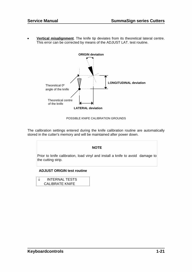
Service Manual SummaSign series Cutters
Vertical misalignment. The knife tip deviates from its theoretical lateral centre.This error can be corrected by means of the ADJUST LAT. test routine.
LONGITUDINAL deviation
LATERAL deviation
Theoretical centreof the knife
Theoretical 0ºangle of the knife
ORIGIN deviation
POSSIBLE KNIFE CALIBRATION GROUNDS
The calibration settings entered during the knife calibration routine are automaticallystored in the cutter's memory and will be maintained after power down.
NOTE
Prior to knife calibration, load vinyl and install a knife to avoid damage tothe cutting strip.
ADJUST ORIGIN test routine
INTERNAL TESTS CALIBRATE KNIFE
Keyboardcontrols 1-21
SummaSign series Cutters Service Manual
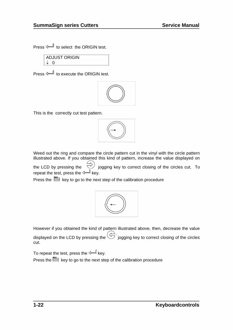
Press to select the ORIGIN test.
ADJUST ORIGIN 0
Press to execute the ORIGIN test.
This is the correctly cut test pattern.
Weed out the ring and compare the circle pattern cut in the vinyl with the circle patternillustrated above. If you obtained this kind of pattern, increase the value displayed on
the LCD by pressing the jogging key to correct closing of the circles cut. Torepeat the test, press the key.
Press the key to go to the next step of the calibration procedure
However if you obtained the kind of pattern illustrated above, then, decrease the value
displayed on the LCD by pressing the jogging key to correct closing of the circlescut.
To repeat the test, press the key.
Press the key to go to the next step of the calibration procedure
1-22 Keyboardcontrols

Service Manual SummaSign series Cutters
ADJUST LAT. test routine
ADJUST LAT 0 1
Press to execute the LAT test.
1 runs from the horizontal line at the bottom to the centre.2 runs from the horizontal line at the top to the centre.3 runs from the centre to the horizontal line at the top.4 runs from the centre to the horizontal line at the bottom.
Carefully check the alignment of the different cuts: the two vertical lines should meetseamlessly precisely in the middle, without any gaps.
Weed out the rectangle and if you obtained the kind of pattern illustrated above,
decrease the value displayed on the LCD by pressing the jogging key to correctclosing of the lines cut.To repeat the test, press the key.
Press the key to go to the next step of the procedure.
Keyboardcontrols 1-23

SummaSign series Cutters Service Manual
However, in case your cut resembles the pattern illustrated above, increase the value
displayed on the LCD by pressing the jogging key to correct closing of the linescut.To repeat the test, press the key.
A complementary test has been added to fine tune the LAT. adjustment. Press the 2 key to perform the vertical test shown above. All the squares should beidentical.
Press the key to go to the next step of the procedure.
ADJUST LONG. test routine
ADJUST LONG 0 1
Press to execute the LONG test.
The test pattern is similar to the LAT-test.Check the quality of the cuts: the end of the vertical cuts should coincide precisely withthe horizontal cuts, without any gaps.
Weed out the rectangle and if you obtained a pattern as illustrated above, decrease the
value displayed on the LCD by pressing the jogging key to correct closing of thelines cut.To repeat the test, press the key.
1-24 Keyboardcontrols

Service Manual SummaSign series Cutters
Press the key to repeat the calibration procedure or press the key to interruptthe routine.
However, if you obtained a pattern as illustrated above, increase the value displayed
on the LCD by pressing the jogging key to correct closing of the lines cut.To repeat the test, press the key.
Press the key to repeat the calibration procedure or press the key to interruptthe routine.
A complementary test has been added to fine tune the LONG. adjustment.Press the 1 key to perform the horizontal test; all the squares should be identical.
CUT BORDER
The CUT BORDER submenu is used to cut the border of the media area which wasdefined during the load sequence. This function is particularly useful if you want toverify the exact cutting area.
MENU PLOT
The MENU PLOT is a hard copy of the present cutter configuration, i.e. the itemsselected in the USER CONFIG submenus described in Section 1.3. The plot isorganised by menu categories to show the current values for the various USERCONFIG 1(->4) configurations. To run this plot, load a sheet of plotting paper andinstall a pen.
Keyboardcontrols 1-25
SummaSign series Cutters Service Manual
NOTE
It is strongly recommended to produce a MENU PLOT hard copy each timeyou alter the cutter configuration. The resulting plot should be kept with thecutter documentation in order to provide other users with details of theactual configurations of the unit.
CONFIDENCE CUT
The CONFIDENCE cut performs an electrical and mechanical test of the cutter to makesure that the cutter is fully operational. A media sheet of at least A3/A- size should beused for this plot.
DIN CUT
The DIN CUT also performs an electrical and mechanical test of the cutter, in order tocheck the cut quality, but also provides the user with feedback on knife setting, knifepressure, knife offset and cutting depth.
This cut is always run as a DIN A4 portrait/A-size image, regardless of the actual sizeof the media loaded. If the media loaded is smaller than DIN A4/A-size, part of theouter box will be clipped (not cut). This cut is always executed in the sequenceprescribed by the ISO DIN standard.
SYSTEM TESTS
The SYSTEM TESTS submenu covers the menu items you only occasionally need toadjust the cutting process.
Press the ENTER key to access the different submenu items which are explained insection 1.6 below.
1-26 Keyboardcontrols

Service Manual SummaSign series Cutters
SYSTEM TESTS
The SYSTEM TESTS menu is a special set of procedures which are not required fornormal cutter operation. Field service personnel, however, will use the SYSTEMTESTS menu occasionally. When in SYSTEM TESTS, the cutter is fully operationaland performs as described in this manual.
LANGUAGE
The MENU LANGUAGE submenu is used to set or modify the dialogue language on
the LCD. Press the or jogging key until the desired language is displayed onthe LCD and press to confirm.The information on the LCD can be displayed in English, French, German, Dutch,Spanish or Italian.
ROM REVISION
Selecting the ROM REVISION option, by pressing the key will furnish the detailson the cutter’s ROM revision. This information is often helpful to technicians whendiagnosing problems over the telephone.
SERVICE PLOT
The SERVICE PLOT provides information about the cutter, which is helpful whenrequesting service for your cutter. The SERVICE PLOT is always plotted at the samesize and should be performed with a pen on paper.
The plot shows the cutter model number, the revision numbers of the installed ROM(Read Only Memory) circuits, the selected baud rate, the resolution and buffer(memory) size.
CAUTION
The following test routines are normally restricted to CalComp Field ServicePersonnel.
Keyboardcontrols 1-27

SummaSign series Cutters Service Manual
SENSOR SETUP
The SENSOR SETUP option is a useful routine to check whether or not the front andrear media sensor are functioning properly and whether the switching levels of thesesensors are correctly set.
CALIBRATION
Calibration allows the length of the lines cut to be adjusted to within the specifications.For instance, if a cut line should measure 100 mm exactly, the cutter can be adjustedfor any discrepancy.
TRACKING TEST
This test allows the tracking quality of the machine to be verified.
FRICTION PLOT
This test routine must be performed with a pen and is used to detect problems with thecutter. The FRICTION PLOT is automatically scaled to fit the currently installed papersize. This test should only be performed by qualified service personnel.
RS232 TEST
The RS232 TEST routine verifies the cutter’s RS-232-C serial communications(transmit data, receive data, and hardware handshaking) circuits. This test does notrequire pen, knife or media to be loaded.
To run the RS-232-C test, proceed as follows :
1. Unplug the RS-232-C data cable from the rear panel of the cutter.
2. Use a loopback test cable to connect pin 2 of the cutter’s data connector to pin 3and pin 7 to pin 8.
3. With RS232 TEST displayed, press the ENTER key. The cutter will start transmittingand receiving data at all available baud rates and parity settings. The length ofthe transmissions will vary because of the different baud rates used. The unitthen checks the hardware handshake lines.
4. Upon completion of the test, remove the loopback test cable from the cutter rearpanel RS-232-C connector.
5. Plug the RS-232-C data cable into the connector.
RAM TEST
This test completely checks the RAM bit for bit.
1-28 Keyboardcontrols

Service Manual SummaSign series Cutters
When running this test the cutter will not respond. After this test, power the cutter off,then on .
INSTALL MENU
The INSTALL MENU routine restores the factory-defined menu settings in all fourUSER CONFIG menus. This test routine can be performed without a tool and withoutmedia.
COIL SETUP
This test is used to calibrate knife and pen pressure and to set the knife and pen“landing”.After adjustment, the value is saved in the system’s non-volatile RAM.To execute this test a tension gauge of ± 100 gr and ± 500 gr is required.In the upper line of the display the desired pressure appears and in the bottom line ofthe display the value that has to be sent to the head to reach this pressure (this valueis between 0 and 127).
LCD CONTRAST
The LCD CONTRAST submenu is used to adjust the contrast (or intensity) of the liquidcrystal display on the control panel.
Press the or jogging key toincrease or reduce the contrast and press to confirm.
Keyboardcontrols 1-29
Blank Page
Replacements Guidelines 2-1
SECTION 2
Replacements guidelines
General
This section contains information on replacing defective parts and adjustment procedures. A step-by-step removal/assembly procedure is provided in this section. On the left page you will find drawingsindicating the position of the parts. Use the last section of this manual for detailed assembly pictures.
Precautions
Observe simple, common sense rules and procedures whilst servicing the unit. They include, but arenot limited to the following:1.
The base of the unit has been assembled on a fixture to assure straightness all along the y-axis.To keep this :DO NOT REMOVE THE SIDE PLATES NOR THE Y-GUIDING.
Unplug the line cords and host cables before transporting the unit to other places.
Reassemble ALL parts (screws, ferrite shield, etc.) to maintain EMI integrity, and guide the loosewires afterwards with tie-wrap in the same manner they were before
Watch for sharp edges on the metal strips etc.
When the covers are off or open:
The printed circuits boards are electrostatically sensitive; use the proper handlingtechniques.
Keep sensors and reflection plates free of scratches and dirt.
Keep the guiding, at least dirtfree where the wheels of the carriage pass.
Replacements Guidelines 2-1
SummaSign Service Manual
2-2 Replacements Guidelines
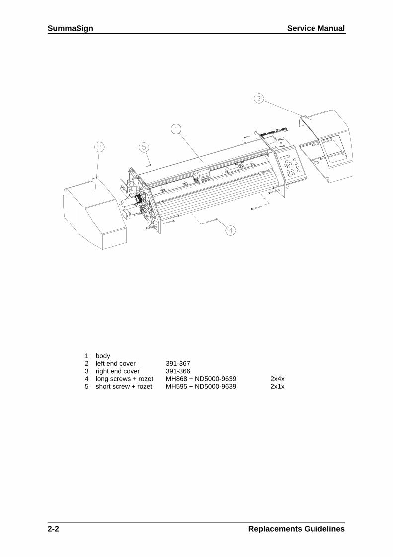
1 body2 left end cover 391-3673 right end cover 391-3664 long screws + rozet MH868 + ND5000-9639 2x4x5 short screw + rozet MH595 + ND5000-9639 2x1x

Service Manual SummaSign
REMOVING THE LEFT-HAND COVER
To remove the left-hand cover, proceed as follows:
2. Remove the five screws (four long screws and a short screw) holding the left-hand cover in place.Three are located at the front, one at the rear and one at the bottom (it is not necessary to turnthe unit upside down to remove the bottom screw). Pay close attention to where each of thescrews goes. They should be returned to their original location when re-installed.
3. Gently tap the top of the cover.
4. Remove the cover.
To re-install, proceed in the reverse order of removal. Make sure to firmly tighten all screws.
REMOVING THE RIGHT-HAND COVER
To remove the right-hand cover, proceed as follows:
5. Remove the five screws (four long screws and one short screw) holding the right-hand cover inplace. Three are located at the front, one at the rear and one at the bottom (it is not necessary toturn the unit upside down to remove the bottom screw).
Caution
The rear screw is located in the top corner of the plate, to the left of the threevertically-aligned screws. Only remove only the screw in the top corner becausethe others serve to hold the PCB in place.
Pay close attention to where each of the screws goes. They should be returned to their originallocation when re-installed.
6. Gently tap the top of the cover.
7. Remove the cover.
To re-install, proceed in the reverse order of removal. Make sure to firmly tighten all screws.
1.!
CAUTION2.3. Make sure that you do not jam any wires between the cover and the sideplate as this may cause considerable damage.4. Give special attention to the flat cables. Protruding parts inside the covercan partly unconnect the flat cables and inflict serious damage to several pcb’s.
5.6.
Replacement Guidelines 2-3

SummaSign Service Manual
2-4 Replacements Guidelines
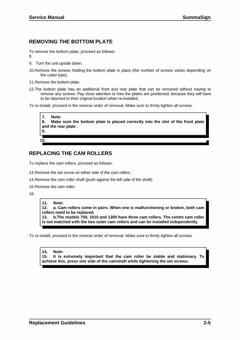
1 body2 bottom plate3 screws # depends on type of machine4 slot for bottom plate
1 camroller assy2 camroller3 camrollershaft4 setcrew
Service Manual SummaSign
REMOVING THE BOTTOM PLATE
To remove the bottom plate, proceed as follows:8.
9. Turn the unit upside down.
10.Remove the screws holding the bottom plate in place (the number of screws varies depending onthe cutter type).
11.Remove the bottom plate.
12.The bottom plate has an additional front and rear plate that can be removed without having toremove any screws. Pay close attention to how the plates are positioned, because they will haveto be returned to their original location when re-installed.
To re-install, proceed in the reverse order of removal. Make sure to firmly tighten all screws.
7. Note:8. Make sure the bottom plate is placed correctly into the slot of the front plateand the rear plate .9.
10.
REPLACING THE CAM ROLLERS
To replace the cam rollers, proceed as follows:
13.Remove the set screw on either side of the cam rollers .
14.Remove the cam roller shaft (push against the left side of the shaft).
15.Remove the cam roller.
16.
11. Note:12. a. Cam rollers come in pairs. When one is malfunctioning or broken, both camrollers need to be replaced.13. b.The models 750, 1010 and 1300 have three cam rollers. The centre cam rolleris not matched with the two outer cam rollers and can be installed independently.
To re-install, proceed in the reverse order of removal. Make sure to firmly tighten all screws.
14. Note:15. It is extremely important that the cam roller be stable and stationary. Toachieve this, press one side of the camshaft while tightening the set screws.
Replacement Guidelines 2-5

SummaSign Service Manual
2-6 Replacements Guidelines
1 body2 motor with encoder3 screws4 belt
1 motor2 capacitor3 connector encoder WATCH ORIENTATION !4 wires motor

Service Manual SummaSign
REPLACING THE X-MOTOR IN THE MODELS 500, 610 AND THE OLDMODEL 750
To replace the X-motor in these models, proceed as follows:
17.Remove the left-hand cover (see Chapter 2.1, Removing the left-hand cover).
18.Remove the connector from the encoder and solder off the black and the red wire to expose the X-motor.
19.Remove the three screws holding the X-motor in place.
20.Remove the X-motor.
To re-install, proceed in the reverse order of removal. Make sure to firmly tighten all screws.
16. Note:
17. When re-installing:
18. a.Make sure the wire of the connector attached to the encoder runs outward.
19. b.Make sure to solder the black wire to the minus (-) entry and the red wire tothe plus (+) entry. The (+) and (-) signs are located in the corners of the motor'slabel.
20. c.Be extremely careful to plug the connector into the correct holes of theencoder.
Move the pulley on the motor shaft to prevent the belt from slipping against the big pulley. Make sureto firmly tighten the set-screw.
Replacement Guidelines 2-7

SummaSign Service Manual
2-8 Replacements Guidelines
1 motor with encoder2 motor without encoder3 gap between belts
1 body2 motor with encoder3 motor without encoder4 screw5 belt
1 motor2 capacitor3 connector encoder WATCH
ORIENTATION !4 wires motor

Service Manual SummaSign
REPLACING AN X-MOTOR IN THE MODELS 750/1010 AND 1300
The models above are equipped with two X-motors. Although both motors are driven, only the onewith the encoder is used for feedback.
REPLACING THE X-MOTOR WITH THE ENCODER
To replace the X-motor with the encoder, proceed as follows:
21.Remove the left-hand cover (see Chapter 2.1, Removing the left-hand cover).
22.Disconnect the connector.
23.Remove the three screws holding the motor in place.
24.Remove the motor.
To re-install, proceed in the reverse order of removal. Make sure to firmly tighten all screws.
21. Note:
22. When re-installing:
23. a.Make sure the wire of the connector attached to the encoder runs outward.
24. b.Make sure to solder the black wire to the minus (-) entry and the red wire tothe plus (+) entry. The (+) and (-) signs are located in the corners of the motor'slabel.
25. c.Be extremely careful to plug the connector into the correct holes of theencoder.
REPLACING THE X-MOTOR WITHOUT THE ENCODER
To replace the X-motor without the encoder, proceed as follows:
25.Remove the left-hand cover (see Chapter 2.1, Removing the left-hand cover).
26.Remove the brown and the orange wire by soldering them off.
27.Remove the three screws holding the motor in place.
28.Remove the motor.
To re-install, proceed in the reverse order of removal. Make sure to firmly tighten all screws.
26. Caution:
27. a.Make sure the brown wire is soldered to the minus (-) entry and the orangewire to the plus (+) entry.
28. b.It is extremely important that the two rotating belts do not touch. Make sureto position each belt correctly to avoid malfunctioning.
Replacement Guidelines 2-9

SummaSign Service Manual
2-10 Replacements Guidelines
1 body2 y-motor3 screw (3x)
1 motor2 capacitor3 connector encoder WATCH ORIENTATION !4 wires motor

Service Manual SummaSign
REPLACING THE Y-MOTOR
To replace the Y-motor, proceed as follows:
29.Remove the right-hand cover (see Chapter 2.1, Removing the right-hand cover).
30.Remove the connector from the encoder and solder off the black and the red wire to expose the Y-motor.
31.Remove the three screws holding the Y-motor in place.
32.Remove the Y-motor.
To re-install, proceed in the reverse order of removal. Make sure to firmly tighten all screws.
29. Note:
30. When re-installing:
31. a.Make sure the wire of the connector attached to the encoder runs outward.
32. b.Make sure to solder the black wire to the minus (-) entry and the red wire tothe plus (+) entry. The (+) and (-) signs are located in the corners of the motor'slabel.
33. c.Be extremely careful to plug the connector into the correct holes of theencoder.
34. d.Move the pulley on the motor shaft to prevent the belt from slipping againstthe big pulley. Make sure to firmly tighten the set-screw.
35.
Replacement Guidelines 2-11

SummaSign Service Manual
2-12 Replacements Guidelines
1 body2 keyboard assy3 nut4 lockwasher5 grounding wire
1 LCD assy2 keyboard3 spacer4 washer5 nut M26 dust cover7 LCD cable
Service Manual SummaSign
REPLACING THE LCD OR THE KEYBOARD
REPLACING THE KEYBOARD
To replace the keyboard, proceed as follows:
33.Remove the right-hand cover (see Chapter 2.2, Removing the right-hand cover).
34.Loosen one end of the flat cable for the head by pulling the flat cable connector up. On both sides ofthe connector cover there is a small protuberance that you can pry up using a screwdriver. Gentlypull the flat cable out of the connector and pull the flat cable loose (it sticks to the other flatcables).
35.Pull the flat cable for the keyboard off the PCB.
36.Pull the flat cable for the LCD off the PCB.
37.Remove the four screws holding the keyboard in place.
38.Remove the keyboard.
To re-install, proceed in the reverse order of removal. Make sure to firmly tighten all screws.
REPLACING THE LCD
To replace the LCD, proceed as follows:
39.Remove the keyboard (see above).
40.Remove the four screws holding the LCD in place.
41.Remove the LCD.
To re-install, proceed in the reverse order of removal. Make sure to firmly tighten all screws.
Replacement Guidelines 2-13

SummaSign Service Manual
2-14 Replacements Guidelines
2a connector paper sensors 4 connector keyboard2b connector cam switch 5 connector LCD screen2c connector y-encoder 6 place for safeguard2d connector x-encoder 7 grounding clamps2e connector main power 8a completely unscrew this one2f connector y-motor 8b just loosen this one a bit2g connector x-motor with encoder 9 vertically aligned screws2h connector x-motor without (*) 10 fan motor connector3 connector flatcable
(*) on the older models on separate pcb
Service Manual SummaSign
REPLACING THE MAIN PCB
The SummaSign and SummaCut cutters manufactured since December 1995 have a different mainPCB from those manufactured before that date.The boards on the new cutters have the logic for the head control on the same main PCB whereasthe parallel input is on an extra board. You can obtain this option by ordering part number 421-174.The new type of boards are fully compatible with the old type of boards, the only difference being theposition of particular connectors, and certain parts, previously situated on the small PCB, that cannow be found on the main PCB.The old type of boards can be exchanged for the new type of boards.
Summarizing, there are two types of main PCBs:
0Type 1: Main PCBs dating from before December
1Type 2: Main PCBs dating from after December 1995
To replace a PCB, proceed as follows:
42.Remove the right-hand cover (see Chapter 2. 2, Removing the right-hand cover).
At the top of the PCB43.
44.Disconnect the various connectors. Pay close attention to the positioning of the connectors. Theyshould be returned to their original location when re-installed.
36. Note:37. In the Type 1 models the connector for the cam roller switch has to beremoved from the small PCB.
45.
46.Remove the flat cable for the head by pulling the flat cable connector up. On both sides of theconnector cover there is a small protuberance that you can pry up using a screwdriver. Gentlypull the flat cable out of the connector.
38. Note:39. In the Type 1 models this connector is located on the top of the small PCB.
47.
48.Remove the flat cable for the keyboard.
49.Remove the flat cable for the LCD.
At the rear of the PCB
50.Remove the safeguard located a few inches above the grounding wires.
Loosen the two grounding clamps so that the earthing wires can be removed.
Replacement Guidelines 2-15

SummaSign Service Manual
2-16 Replacements Guidelines
2a connector paper sensors 4 connector keyboard2b connector cam switch 5 connector LCD screen2c connector y-encoder 6 place for safeguard2d connector x-encoder 7 grounding clamps2e connector main power 8a completely unscrew this one2f connector y-motor 8b just loosen this one a bit2g connector x-motor with encoder 9 vertically aligned screws2h connector x-motor without (*) 10 fan motor connector3 connector flatcable
(*) on the older models on seperate pcb
Service Manual SummaSign
At the front of the PCB
51.Remove the left screw holding the power entry module in place and sufficiently loosen the rightscrew of the power entry module.
At the side of the PCB
52.Remove the three vertically-aligned screws located on the right-hand cover.
On the bottom of the PCB
53.Remove the fan motor connector.
40. Note:41. In the Type 1 models the connectors for the sensors also have to be removed.
54.
55.Remove the PCB.
To re-install, proceed in the reverse order of removal. Make sure to firmly tighten all screws.
42. Note:
43. a. When re-installing, be extremely careful to plug the connectors into thecorrect holes.
44. See the drawing in section 7 for the exact positioning of the connectors.The drawing shows the PCB of a new model (Type 2). The old model (Type 1) differson the following points:
45. The connector for the switch is located at the centre on the top of thesmall board.
46. The connector for the head is located right of centre on the top of thesmall PCB.
47. The connectors for the sensors are at the bottom of the main PCB.
48. The connector for the second X-motor is located on the small board at theback of the PCB.
49. Each connector on the PCB has a reference.
50. b. Once the new PCB has been installed, it is very important that the datastored on the PCB be brought in line with the head and vice versa. See section 4 oncalibration.
Replacement Guidelines 2-17

SummaSign Service Manual
2-18 Replacements Guidelines
1 main pcb2 small pcb3 cover plate4 screws5 hex nuts

Service Manual SummaSign
REPLACING THE SMALL PCB ON THE MAIN PCB
The SummaSign and SummaCut D500 cutters manufactured since December 1995 have a differentmain PCB from those manufactured before that date. This has also had consequences for the smallPCB.There are currently two types of main PCBs:
Type 1: Main PCBs dating from before December 1995
Type 2: Main PCBs dating from after December 1995
The small board on Type 1 main PCBs has head driver and head rotation functions and a parallelport.The small board on Type 2 main PCBs only has a parallel port.
To replace the small PCB, proceed as follows :
56.Remove the right-hand cover (see Chapter 2.2, Removing the right-hand cover).
57.Remove the main PCB (see Chapter 2.8, Replacing the main PCB).
58.Remove the screw on either side of the parallel port.
59.Remove the clamp on either side of the serial port.
60.Remove the cover.
61.Remove the two screws holding the small PCB in place.
62.Remove the screw or the two screws on the right-hand side that hold the drivers against the smallPCB (this only applies to Type 1 PCBs).
63.Remove the small PCB.
64.To re-install, proceed in the reverse order of removal. Make sure to firmly tighten all screws.
2The old PCB consists of: a 3-pin connector for the X-motor. Use the cable coming from the motor with the encoder if you are dealing with a
unit with 2 motors. Connect the motor without encoder to the small satellite board. 3-pin connector for the Y-motor; a 3-pin connector coming from the transformer; a 4-pin connector coming from the X-motor encoder; a 4-pin connector coming from the Y-motor encoder; 6 connectors that are not used.On the right-hand side you see the connectors for the LCD and the keyboard.On the bottom you find: a 2-pin connector coming from the fan motor; a 5-pin connector coming from the sensor; 2 connectors that are not used.
Replacement Guidelines 2-19

SummaSign Service Manual
2-20 Replacements Guidelines
1 cover head2 head3 screws cover head4 position screws to hold head5 flatcable

Service Manual SummaSign
REPLACING A DRAG HEAD OR A TANGENTIAL HEAD
Below is the description for the replacement of a standard drag head. The procedure described isalso roughly applicable to the replacement of a tangential head. The areas where the replacementprocedure for the tangential head differs are indicated between brackets and in italics.The only major difference between replacing a drag knife and a tangential knife is the positioning ofthe screws on the carriage plate.
To remove the drag head, proceed as follows:
65.Take the knife holder out of the drag head.
66.Remove the front cover of the drag head by loosening the two (three) screws .
67.Loosen the flat cable by pulling the flat cable connector cover up. On both sides of the connectorcover there is a small protuberance that you can pry up using a screwdriver. Gently pull the flatcable out of the connector
68.Remove the drag head. To do this, loosen the three screws with two counterclockwise rotationsusing a small diameter screw driver and lift the head upwards to remove it from the screws.
To re-install the drag head, proceed as follows:
69.Place the head back onto the screws. Tighten the screws with a 1 1/2 clockwise rotation. Do nottighten them firmly because the height and position of the head still need to be adjusted.
70.Put the knife holder into the drag head. (Put the nose piece into the tangential head).
71.
51. Caution:52. Make sure the tip of the knife does not protrude.
72.
73.Secure the knife holder.
74.
53. Note:54. This only applies to the re-installation of a drag head.
75.76.Adjust the height and position of the head.
77.
78.The standard operating procedure for doing this is described in the SummaSign Upgrade Kit(p/n 391-950).
55. Note:56. The operating procedure described in the Upgrade Kit applies to a tangentialhead. However, the procedure to be followed for a drag head is roughly applicable.
Replacement Guidelines 2-21
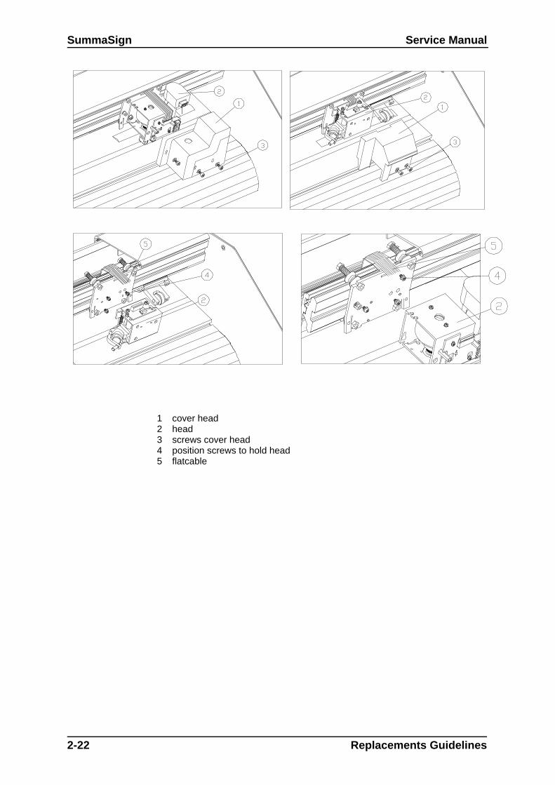
SummaSign Service Manual
2-22 Replacements Guidelines
1 cover head2 head3 screws cover head4 position screws to hold head5 flatcable

Service Manual SummaSign
Apart from the standard adjustment tools used in the standardoperating procedure, you can use an ordinary 3½" disk toadjust the height and position of the head. To do this, proceedas follows:
a. Put the disk against the drag head (the same way as youwould put an adjustment plate against it) to verify that the draghead is positioned perpendicularly to the cutting surface.
b. Slide the disk under the knife holder. If the disk touches theknife holder this means that the head is mounted too low.Readjust the mounting of the head.
79.
80.Firmly tighten the screws once the drag head is properly positioned.
81.Put the flat cable back into the connector and close the connector. To ensure good contact, the flatcable must be positioned as deeply as possible and in the middle of the connector.
82.Remount the front cover of the head and firmly tighten the screws.
83.Proceed in the reverse order of removal. Make sure to firmly tighten all screws.
84.
57. Note:58. Now that you have replaced the head, it is extremely important that you bringthe data stored on the PCB in line with the head and vice versa. See Chapter 11,Configuration of the head or the PCB for detailed information on how to do this.
59.60.
Replacement Guidelines 2-23

SummaSign Service Manual
61.62.
2-24 Replacements Guidelines
1 body2 flatcable path3 loop may not touch anything when head is completely on the left

Service Manual SummaSign
REPLACING THE FLAT CABLE FOR THE HEAD
Below is the description for the replacement of the flat cable in small cutters. Large cutters - themodels D/T 1300, D/T 1010 (plus) - have an extra strip that is located along the flat cable. Thepurpose of this additional strip is to prevent the flat cable from crumpling. For more information, seeAdditional strip in larger units at the end of this chapter.
To replace the flat cable for the head, proceed as follows:
85.Remove the left-hand cover (see Chapter 1, Removing the left-hand cover).
86.Remove the right-hand cover (see Chapter 2, Removing the right-hand cover).
87.Remove the two screws on either side of the top cover.
88.Remove the top cover.
89.Loosen one end of the flat cable (the one attached to the PCB) by pulling the flat cable connectorcover up. On both sides of the connector cover there is a small protuberance that you can pry upusing a screwdriver. Gently pull the flat cable out of the connector.
90.Pull the flat cable for the head off the flat cable for the keyboard.91.
63. Note: 64. Pay close attention to the way the flat cable has been folded. It is advisable tofold the flat cable in exactly the same way when re-installed.
92.
93.Loosen the flat cable which has been glued to the inner side of the shaft's upright edge.
94.Remove the two screws (three screws in the case of a T-head) of the top cover of the head holdingthe flat cable in place.
95.Remove the cover.96.
65. Note:66. Pay close attention to the way the flat cable has been folded. The flat cablewill need to be folded in exactly the same way when re-installed.67. Loosen the end of the flat cable attached to the head. Follow the sameprocedure as before (see point 5).
Replacement Guidelines 2-25

SummaSign Service Manual
2-26 Replacements Guidelines
1 additional strip2 glued for about 2cm3 flatcable
1 flatcable2 this edge is 110mm3 screw to hold flatcable holder4 screws to hold flatcable clamp5 flatcable holder6 flatcable clamp

Service Manual SummaSign
To re-install, proceed as follows:
97.Put the flat cable into the connector of the head and close the connector. To ensure good contact,the flat cable must be positioned as deeply as possible and in the middle of the connector.
98.
68. Note:69. If the flat cable is connected to a drag head it is advisable to allow for ±7centimeters of slack. This slack is necessary to be able to upgrade to a tangentialhead,the connector of whichis located in a lower position.
99.
100.Put the flat cable across the top of the head and fold it correctly .
101.102.Remount the top cover of the head. Press the cover down while firmly tightening the screws. Check
that the up/down part of the head can move freely.
103.Remount the flat cable clamp. Check that the flat cable runs parallel to the inner side of the shaft'supright edge and that the up/down part of the head can move freely.
104.Slide the flat cable in between the upright edge of the shaft and the top of the head.
105.Bring the head all the way to the left. Make a loop to allow the head to move unhampered along thelength of the unit.
70. Caution:71. Make sure the loop is neither too long nor too short. A very long loop may getcaught behind other parts and break. A very short loop may break as the headmoves along the length of the unit.
106.Glue the flat cable to the inner side of the shaft's upright edge, starting from the middle.
107.Slide the flat cable through the slot on the right-hand side of the shaft.
108.Put the flat cable into the connector and close the connector. The flat cable must be positioned asdeeply as possible in the middle of the connector to have good contact.
109.Fold the cable into the correct position and press it onto the flat cable for the keyboard.
110.Proceed in the reverse order of removal. Make sure to firmly tighten all screws.
111.
Additional strip in larger units:
As mentioned at the beginning of this chapter, larger units have an additional strip that runs alongsidethe flat cable to prevent the flat cable from creasing. If you need to replace this strip make sure youinsert the new strip as follows:112.
113.Glue ± 2 cm of this end of the strip to the shaft's upright edge.
114.Glue the other end of the strip to the other upright edge of the shaft starting at the protrusion shownin the figure on page 2-26.
Replacement Guidelines 2-27
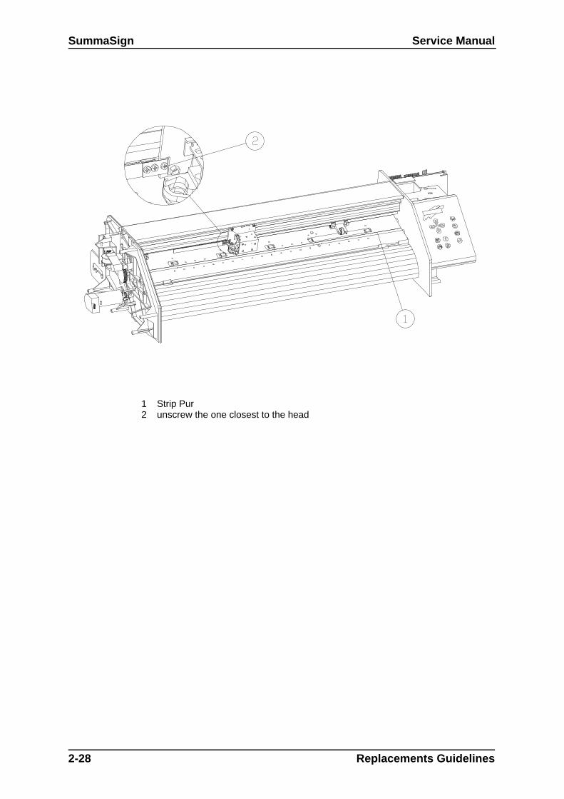
SummaSign Service Manual
2-28 Replacements Guidelines
1 Strip Pur2 unscrew the one closest to the head

Service Manual SummaSign
REPLACING THE Y-BELT
To replace the belt, proceed as follows:
115.Remove the left-hand cover (see Chapter 2. 1, Removing the left-hand cover).
116.Remove the right-hand cover (see Chapter 2.2, Removing the right-hand cover).
117.Remove the 2 screws holding the belt against the carriage plate. One is located to the left of thehead and the other to the right.
118.Remove the belt.
To re-install, proceed as follows:
119.Screw one end of the belt firmly against the carriage plate.
120.Put the belt around the left-hand pulley. Pull it along the length of the unit and put it around theright-hand pulley.
121.Screw the other end of the belt firmly to the carriage plate.
122.Proceed in the reverse order of removal. Make sure to firmly tighten all screws.
72. Note:73. Because the belt is equipped with a springload system, the belt tension neednot be adjusted.
123.
REPLACING THE CUTTING STRIP
To replace the cutting strip, proceed as follows:
124.Loosen the cutting strip on the left-hand (or right-hand) side .
125.Gently pull the cutting strip out of the strip slot.
126.Cut the new cutting strip to the correct length and stick it to the unit.
127.
74. Note:75. The newer models all have cutting strips with the tape included. There are twocutting strips. They have the following part numbers:76. 391-386 for all the models 500/610 and 750;77. 391-886 for all the models 1010 and 1300.
78.
79. Caution:80. In older models, the strip is glued to the unit. To replace it with the new type ofstrip, proceed as follows:81. 1. Loosen the strip on the left-hand (or right-hand) side.82. 2. Place a chisel under the strip and move gently along the length of the unit.83. 3. Remove any debris and thoroughly clean the strip slot.
128.
129. Cut the new strip to the correct length and stick it to the unit.
Replacement Guidelines 2-29

SummaSign Service Manual
130.
2-30 Replacements Guidelines
1 body2 fan3 fan guard4 screws + washers5 front sensor6 rear sensor

Service Manual SummaSign
REPLACING THE SENSORS
Cutters are equipped with two sensors. One is located at the front and the other at the rear of themachine.
84. Note:85. When one sensor is malfunctioning it is advisable to replace both sensors.Experience has shown that soon after replacing the broken sensor, the other sensortends to start malfunctioning as well. Therefore, to prevent having to perform thesame repair twice within a short span of time, it is advisable to replace bothsensors.
To replace the sensors, proceed as follows:
131.Remove the right-hand cover (see Chapter 2.2, Removing the right hand cover).
132.Turn the unit upside down.
133.Remove the bottom plate (see Chapter 2.3, Removing the bottom plate).
134.Remove the screws holding the two sensors in place. Pay close attention to the positioning of thedistance sleeves. They should be returned to their original location when re-installed.
135.Disconnect the other end of the sensor wire from the PCB.
136.Remove the sensors.
To re-install, proceed in the reverse order of removal. Make sure to firmly tighten all screws.
86. Caution:87. Make sure the sensor wire does not touch the drum. The rotating drum maydamage the wire and cause malfunctioning.
137.
REPLACING THE FAN MOTOR138.
To replace the fan motor, proceed as follows:
139.Remove the right-hand cover (see Chapter 2.2, Removing the right hand cover).
140.Turn the unit upside down.
141.Remove the bottom plate (see Chapter 2.3, Removing the bottom plate)
142.Remove the four screws holding the fan motor in place.
143.Disconnect the other end of the fan motor wire from the PCB.
144.Remove the fan motor.
To re-install, proceed in the reverse order of removal. Make sure to firmly tighten all screws.
88. Caution:89. Do not overtighten the 4 screws holding the fan in place as this may bend thefan's mounting flanges and cause malfunction.
90.
Replacement Guidelines 2-31

SummaSign Service Manual
91.
2-32 Replacements Guidelines
1 body2 drum3 screws # depending on the type 4 pulley5 see remark in text
det1 push all the bearing blocks in the same directiondet2 equal distancesdet3 push the pillow blocks against the sleeves
Service Manual SummaSign
REPLACING THE DRIVE DRUM
To replace the drive drum, proceed as follows:
145.Remove the left-hand cover (see Chapter 2. 1, Removing the left-hand cover).
146.Turn the unit upside down.
147.Remove the bottom plate (see Chapter 2.3, Removing the bottom plate).
148.Remove the four screws holding the fan motor in place. Put the fan motor to the side to expose thedrive drum.
149.Remove the screw of the sensor that goes across the drive drum. Put the sensor to the side toexpose the drum.
150.Remove the various screws holding the drum sleeves in place. The number of sleeves variesdepending on the cutter type.
151.Remove the three screws holding the X-motor(s) in place and put the motor to the side. It is notnecessary to disconnect the wires connected to the motor.
152.Remove the belt.
153.Loosen the two setscrews holding the drive drum pulley in place.
154.Pull the pulley out to its full extent. The pulley need not be removed from the unit.
155.Remove the drive drum.
92. Note:93. Because all the sleeves of the drive drum are accurately matched, it is notpossible to replace just one sleeve.
To re-install, proceed as follows:
156.Put the drum into the shaft in the correct position. The largest sleeve should be to the side of thekeyboard.
157.Put the screws into the blocks but do not tighten them yet.
94. Note:95. It is very important that the drive drum be stable and stationary to prevent themedia from shifting about. To achieve this, proceed as follows:96. a.Secure the block to the left (or right) of the large sleeve by tightening itsscrews. Make sure the block is positioned perpendicularly over the holes and thatthe long sleeve is positioned in the middle of the hole in the base plate.97. b.Press the block situatedto the right (or left) of the large sleeve firmly againstthe sleeve and tighten the screws of the block.
158.
159.Now firmly tighten the screws of the other blocks. Make sure they are positioned straight and thatthey do not have any play. Gently press the blocks against the sleeves when tightening thescrews.
160. Thoroughly clean the strip slot.
161.Push the pulley back into its place.
Replacement Guidelines 2-33

SummaSign Service Manual
162.
2-34 Replacements Guidelines
1 body2 drum3 screws # depending on the type 4 pulley5 see remark in text
det1 push all the bearing blocks in the same directiondet2 equal distancesdet3 push the pillow blocks against the sleeves
Service Manual SummaSign
163.
98. Note:99. Make sure the setscrew is positioned correctly so that it locks itself into theslot.
164.
165.Firmly tighten the screws of the drive drum pulley.
166.Put the belt back into its original position.
167.Re-install the X-motor. Make sure to properly tighten all screws.
168.Re-install the fan motor.
169.Re-install the sensor wire.
170.Proceed in the reverse order of removal. Make sure to firmly tighten all screws.
171.
100. Caution:101. Make sure the sensor wire does not touch the drive drum. The rotating drummay damage the wire and cause malfunctioning.
172.
102. Note:103. Not all the different type of machines have this last bearing block.104. If there is one make sure it is pushed to the side plate (a small ring insidemakes sure the drum is grounded)105. If there is none, check for a small brush which touches the shaft of the drum.If it is worn down, replace it. Here the brush ensures that the drum is grounded.
Replacement Guidelines 2-35

SummaSign Service Manual
106.
107.
2-36 Replacements Guidelines
Blank page

Maintenance and Cleaning 3-1
SECTION 3
MAINTENANCE
The SummaSign cutter range has a number of sliding surfaces made of smooth metalsand plastics. They are virtually friction-free and require no lubrication. They will,however, collect dust and lint which may affect the performance of the cutter. Keep thecutter as clean as possible by using a dust cover. When necessary, clean the unit witha soft cloth dampened with isopropyl alcohol or mild detergent. Do not use abrasives.
Maintenance and Cleaning 3-1

SummaSignT-sesiceUser’s Ma
CLEANING THE DRIVE SYSTEM
After a time, the sleeves of the drive drum may become clogged with accumulatedresidue from the media. This situation may affect traction as the media will tend to slipbetween the pinch rollers and the drive sleeves.
To clean the drive sleeves, proceed as follows:
1. First disable the sensors by covering them, or via the configuration menu (see1.4.12 Media Sensor).
2. Place the cutter in local operation. (See Section 1.2.2.) Local operation will allowyou to use the control panel jogging keys, even when no media is loaded.
3. Remove the backing from a piece of vinyl. Place the vinyl with the tacky sidedown between one of the pinch rollers and a drive sleeve. Lower the pinch rollerarm.
4. Use the and jogging keys to move the piece of vinyl backward andforward several times, until all residue is removed from the drive sleeves.
5. Raise the pinch roller arm and remove the piece of vinyl media.
6. Repeat steps 3 through 5 for the other drive sleeves.
7. Set the cutter's power switch to OFF.
SLEEVE
VINYL STRIP PINCH ROLLER
TACKY SIDE ON BOTTOM
CLEANING OF THE DRIVE SLEEVES
3-2 Maintenance and Cleaning

Service Manual SummaSignT-se
CLEANING THE SENSORS
After a certain time, the sensor may become dirty with accumulated residue from themedia. This situation may cause malfunctioning of the cutter.
To clean the sensor area, proceed as follows:
1. The sensors are located on the cutter’s right side. One sensor is located on thefront platen, the other sensor is located on the rear platen.
LOCATION OF THE SENSORS
2. To keep the sensors clean, it is sufficient to wipe them out now and then with acotton swab.
Maintenance and Cleaning 3-3

SummaSignT-sesiceUser’s Ma
CLEANING THE NOSE PIECE
CLEANIN
The nose piece may become dirty with accumulated residue from the vinyl and willresult in poor cut quality.
To clean the nose piece, proceed as follows:
1. Gently take out the knife or ball-point pen by turning the knife holder anticlockwise.
2. Observe the orientation of the nose piece first and then push it out of its holder.
3. Remove any remaining vinyl residue using a brush or a pair of tweezers.
4. Place the nose piece back .
5. Install the knife or ball-point pen holder as described in section 1.7.
3-4 Maintenance and Cleaning
Service Manual SummaSignT-se
3.2. OPERATING VOLTAGE CONVERSION
Maintenance and Cleaning 3-5

SummaSignT-sesiceUser’s Ma
OPERATING VOLTAGE CONVERSION
The power entry module cover shows four possible AC voltage settings (100 V, 120 V,220 V and 240 V). The pin in one of the holes indicates the cutter's active voltagesetting. If this setting does not match the voltage supplied to your site, you mustchange the voltage BEFORE powering on the cutter.
When changing the voltage setting, you will also have to change the fuses asappropriate to the voltage.
To change the fuse(s), remove the fuse(s) from the fuse box behind the cover plate ofthe power entry module.
For 100 or 120 V AC operation of cutters with 1 x-motor Pro unly 1.0 A Slo-Blo fuses.For 100 or 120 V AC operation of cutters with 2 x-motorsT750T,only 1.25 A Slo-Blofuses.For 220 or 240 V AC operation of cutters with 1 x-motor , Pr0.5 A Slo-Blo fuses.For 220 or 240 V AC operation of cutters with 2 x-motors /T1010 Pro/TusSlo-Blo fuses.
NOTE
Always make sure that you are using the correct fuses for yourvoltage selection.
POWER ENTRY MODULE
3-6 Maintenance and Cleaning

Service Manual SummaSignT-se
Maintenance and Cleaning 3-7
blank page

Calibration 4-1
SECTION 4
Calibration
General
This section contains information on the calibration of replaced parts and on the recalibrationof worn down parts. Each time a unit is serviced, check this section to see which calibrationhas to be or can be done.
Calibration 4-1

SummaSign Service Manual
MACHINE TYPE
The machine type has to be reset when:
The pcb has been changeda “special init” has been done
Configuration of the pcb:
via keyboard:
1. Initiate a start-up in Factory Set-up Mode (FSM mode or 3-key mode).Do this by switching on the unit while simultaneously pressing the up/down key, the"1" key and the Enter key until the message "Standard init" appears on the LCD.
1. Caution:2. WHEN STARTING IN 3-KEY MODE, NO LOAD PROCEDURE IS CARRIED
OUT. TO MAKE THE UNIT OPERATIONAL, A LOAD PROCEDURE HAS TO BE
CARRIED OUT (SEE USERS MANUAL). IF THIS LOAD PROCEDURE IS NOT
CARRIED OUT, THE UNIT MAY CRASH.
2.Use the arrow keys to select "Standard init" or "Special init". If you select "Specialinit" the default values are put into the NVRAM. It is advisable to use "Special init" ifthe unit does not start with "Standard init" or if the unit is completely disordered.
3. Caution:4. WHEN THE MACHINE HAS BEEN STARTED UP IN “SPECIAL INIT” THEN
EVERY PARAMETER IN THE MACHINE HAS BEEN DEFAULTED.
In 3-key mode the following extra items appear under system tests (along withseveral others, such as "Coil set-up", which are always available).:
a. Quality plotb. Set Margin: to set the marginsc. Burn in: only used in factoryd. Autobalance: only used in factorye. Set-up machine: to set the unit typef. Set-up tang. : to configure the tangential headg. Plot time h. System reg. : only used in factoryi. NEC values: only used in factoryj. ROM to flash: to flash from standard ROMs to flash EPROMs (to be used only
when the flash EPROM is broken). (not in the old type boards).
4-2 Calibration
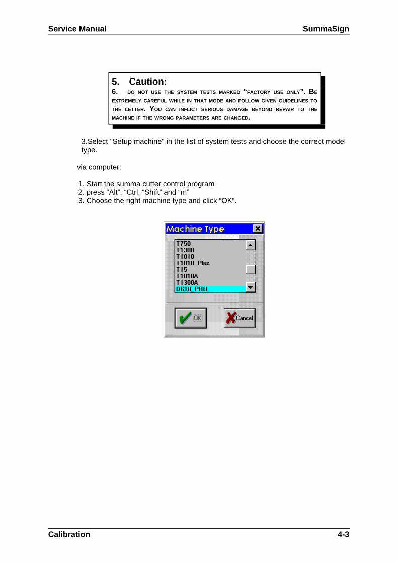
Service Manual SummaSign
5. Caution:6. DO NOT USE THE SYSTEM TESTS MARKED “FACTORY USE ONLY”. BE
EXTREMELY CAREFUL WHILE IN THAT MODE AND FOLLOW GIVEN GUIDELINES TO
THE LETTER. YOU CAN INFLICT SERIOUS DAMAGE BEYOND REPAIR TO THE
MACHINE IF THE WRONG PARAMETERS ARE CHANGED.
3.Select "Setup machine" in the list of system tests and choose the correct modeltype.
via computer:
1. Start the summa cutter control program2. press “Alt”, “Ctrl, “Shift” and “m”3. Choose the right machine type and click “OK”.
Calibration 4-3
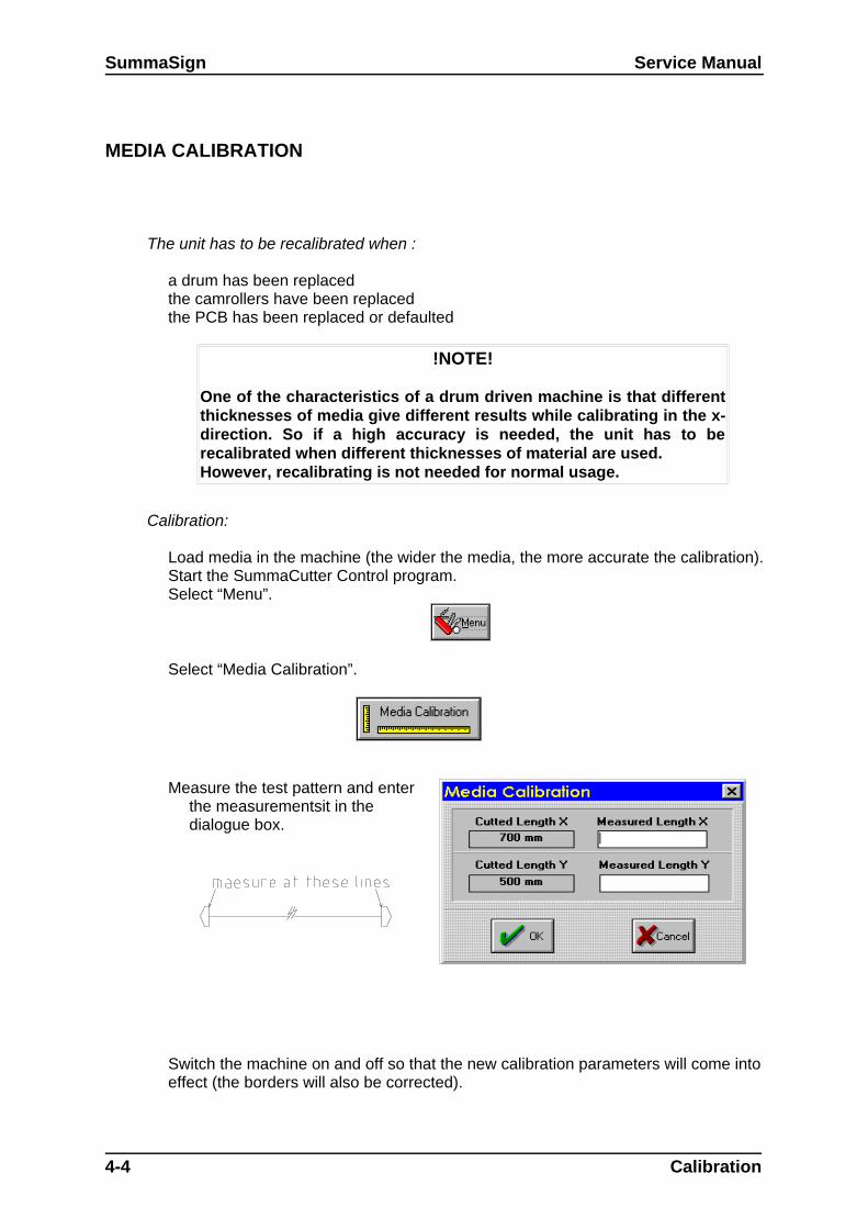
SummaSign Service Manual
MEDIA CALIBRATION
The unit has to be recalibrated when :
a drum has been replacedthe camrollers have been replacedthe PCB has been replaced or defaulted
!NOTE!
One of the characteristics of a drum driven machine is that differentthicknesses of media give different results while calibrating in the x-direction. So if a high accuracy is needed, the unit has to berecalibrated when different thicknesses of material are used.However, recalibrating is not needed for normal usage.
Calibration:
Load media in the machine (the wider the media, the more accurate the calibration).Start the SummaCutter Control program.Select “Menu”.
Select “Media Calibration”.
Measure the test pattern and enterthe measurementsit in thedialogue box.
Switch the machine on and off so that the new calibration parameters will come intoeffect (the borders will also be corrected).
4-4 Calibration

Service Manual SummaSign
Calibration 4-5

SummaSign Service Manual
HEAD CALIBRATION
4-6 Calibration
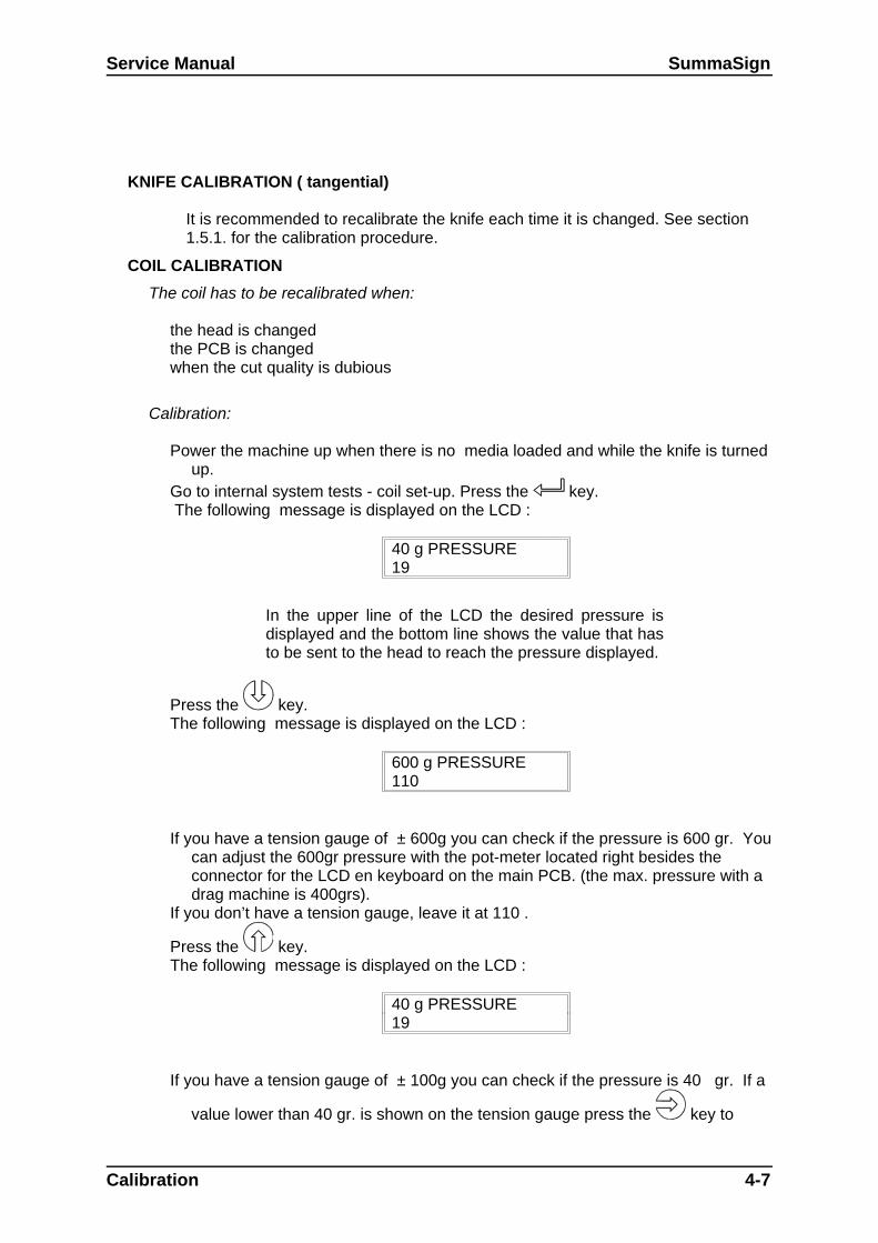
Service Manual SummaSign
KNIFE CALIBRATION ( tangential)
It is recommended to recalibrate the knife each time it is changed. See section1.5.1. for the calibration procedure.
COIL CALIBRATION
The coil has to be recalibrated when:
the head is changedthe PCB is changedwhen the cut quality is dubious
Calibration:
Power the machine up when there is no media loaded and while the knife is turnedup.
Go to internal system tests - coil set-up. Press the key. The following message is displayed on the LCD :
40 g PRESSURE19
In the upper line of the LCD the desired pressure isdisplayed and the bottom line shows the value that hasto be sent to the head to reach the pressure displayed.
Press the key.The following message is displayed on the LCD :
600 g PRESSURE110
If you have a tension gauge of ± 600g you can check if the pressure is 600 gr. Youcan adjust the 600gr pressure with the pot-meter located right besides theconnector for the LCD en keyboard on the main PCB. (the max. pressure with adrag machine is 400grs).
If you don’t have a tension gauge, leave it at 110 .
Press the key.The following message is displayed on the LCD :
40 g PRESSURE19
If you have a tension gauge of ± 100g you can check if the pressure is 40 gr. If a
value lower than 40 gr. is shown on the tension gauge press the key to
Calibration 4-7

SummaSign Service Manual
adjust. If a value higher then than 40 gr. is recorded on the tension gauge use
the key to adjust.If you don’t have a tension gauge leave it at 19.
Insert the drag knife holder into the head.
Press the key to adjust the drag knife landing pressure. The following messagewill be displayed :
DRAG LANDING14
Press the key repeatedly until the drag-knife moves upwards (value around2).
Press the key repeatedly until the drag knife holder moves down (valuearound 11).
Press the key another three times.
Insert the ball-point holder into the head.
Press the key to adjust the ball-point pen landing pressure. The followingmessage will be displayed :
PEN LANDING14
Press the key repeatedly until the ball-point pen moves upwards (valuearound 2).
Press the key repeatedly until the ball-point pen holder moves downwards(value around 11)
Press the key another three times.
Insert the knife holder into the head (the knife may not stick out).
Press the key to adjust the ball-point pen landing pressure. The followingmessage will be displayed :
TANG LANDING14
Press the key repeatedly until the tangential knife goes in the up position(value around 2).
Press the key repeatedly until the tangential knife moves down (value around11)
Press the key another three times.
Press the (ONLINE) key and power the machine down.
4-8 Calibration

Service Manual SummaSign
! NOTE!For a good cutting quality, the landing values must be at least 3 less then the40g pressure
Calibration 4-9

SummaSign Service Manual
OPOS CALIBRATION (optional)
NORMAL CALIBRATION
The CALIBRATION OPOS sub-menu is used to calibrate the OPOS (Opticalpositioning system).This calibration is normally done in the factory. When the system is no longerworking precisely a calibration test must be performed. Calibration allows to fixthe exact distance between the knife tip and the sensor.
To calibrate the optical system, proceed as follows:
1. Power up the unit and load a piece of black vinyl with a white backing. The loadprocedure is described in section 1.
2. Set the origin on a clean, blank part of the vinyl.
3. Press the key (MENU) key until the message ‘INTERNAL TEST’ is displayedon the LCD.
INTERNAL TESTS
4. Press the jogging key until the message ‘ CAL OPOS’ is displayed.
INTERNAL TESTS CAL. OPOS
Press the key to confirm the selection.
The cutter will now cut out a rectangle.
5. The message ‘WEED RECTANGLE’ will appear on the display:
WEED RECTANGLE
4-10 Calibration

Service Manual SummaSign
PRESS MENU
Weed carefully with tweezers the rectangle cut and press the key.
The cutter will now measure the rectangle and set its calibration parameters.
Calibration 4-11

SummaSign Service Manual
FINE TUNING
The Opos system has to be fine tuned when:
the normal calibration didn’t do the job.the Opos system has been removed from the head.The markers are extremely glossy (sometimes in cas of photoquality with thermal
wax transfer).
Calibration:
Load vinyl.Make sure the Opos system is placed perpendicular on the media.Go to the internal test - system test-optical sensor.Remove the black piece of vinyl from the Opos sensor.Turn the left pot meter 15 turns CCW and the 8 turns CW .Place the sensor top above a piece of white matt media.Turn the right pot meter CCW until the LCD display shows a value higher than 300.
Then turn CW until the value doesn’t decrease anymore and turn 1/8 of a turnCCW.
Place the sensor above a glossy piece of black material. Turn the left pot meterCCW until the display doesn’t increase anymore (more than 8 turns is useless).This value is usually between 1950 and 2000.
Continue with the normal calibration.
!NOTE!When the OPOS system still fails to work properly, do the fine tuning onthe media giving trouble. Change the “matt white media” with thetroublesome media and change “glossy black media” with the marker onthe troublesome media.If everything else fails just try to make the difference, between the readoutabove the markers and the readout above the media, more than 800.The left pot meter changes the gain and the right pot meter changes thethreshold level between black and white.
4-12 Calibration
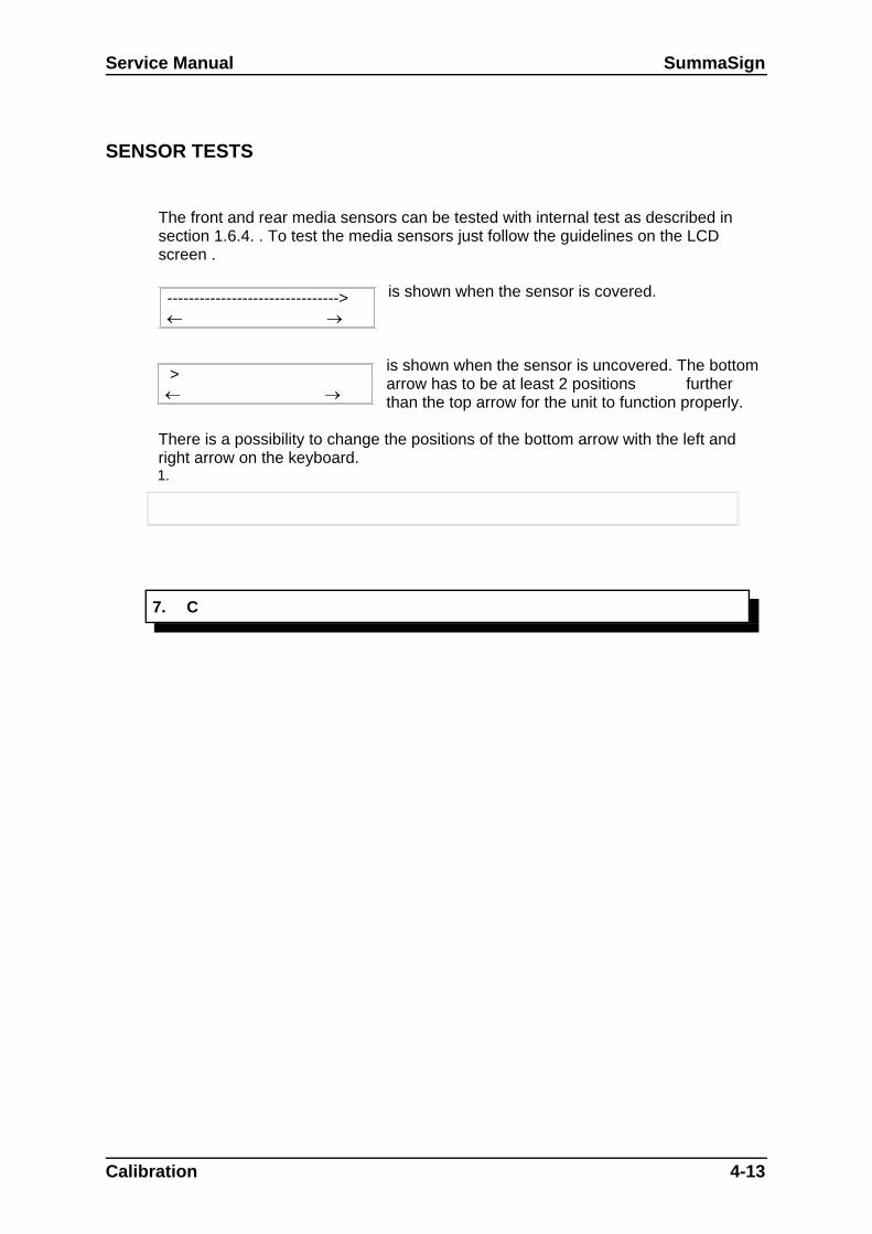
Service Manual SummaSign
SENSOR TESTS
The front and rear media sensors can be tested with internal test as described insection 1.6.4. . To test the media sensors just follow the guidelines on the LCDscreen .
is shown when the sensor is covered.
is shown when the sensor is uncovered. The bottomarrow has to be at least 2 positions furtherthan the top arrow for the unit to function properly.
There is a possibility to change the positions of the bottom arrow with the left andright arrow on the keyboard.1.
7. C
Calibration 4-13
-------------------------------->
>

Troubleshooting-Error Codes 5-1
SECTION 5
Troubleshooting - Error codes
General
This section contains information on the error codes which can appear on the LCD screen. Astep-by-step procedure is provided in this section to prevent this error.
Troubleshooting-Error Codes 5-1

SummaSign Service Manual
MOTOR HOT
Cause:
Heavy media can overload the motors, especially the X-motor. The µP on the PCBcalculates the power dissipated in the motors. When this dissipation becomes too high, themessage MOTOR HOT appears. This is not a fatal error. After a while this message willdisappear and the machine will continue its operation.
Action:
1. Wait until the motor has cooled down to an acceptable level.2. Lower the speed using the menu and use a lower knife pressure if possible.3. Use lighter or smaller media.4. Check the cam rollers, replace any damaged cam rollers.5. Call CalComp for assistance. A system register may have changed the default value.6. Check whether the drive drum is turning smoothly (first switch the machine off and place
the cam rollers in the up-position). Replace motor and/or drum.
ERROR IN X-AXIS
Cause:
The drum motor cannot move to the required position. This is a fatal error. It can only besolved by turning the power off and then on again. This error is usually caused by a mediacrash in the machine.
Action:
7. Remove the crashed media and restart the machine. Should this happen rather frequently,the cause can be :
knife depth or pressure is not well set. bad tracking because an unstabilised media type is used. bad tracking because the humidity is too high or too low. bad tracking because an unapproved type of media is used. the media hit something on the floor while cutting. the media shows already different tracks, so that the media does not know
which track to follow.8. Lower the speed of the media.9. Check whether the drive drum turns smoothly (first turn the power off and place the cam
rollers in the up-position).10.If the error in the x-axis happens at start-up, check the x-axis motor, the encoder
connectors and the cables.11.Replace the X-motor encoder.12.Replace the PCB.13.
5-2 Troubleshooting-Error Codes
Service Manual SummaSign
ERROR IN Y-AXIS POSITION
Cause:
The motor driving the machine head cannot move to the position wanted. This is a fatal error.It can only be solved by turning the power off and then on again. This error is usually causedby a media crash.
Action:
14.Remove the crashed media and restart the machine.15.Lower the speed and/or the knife pressure.16.Check whether the head moves smoothly (first turn the power off and position the cam
rollers on the outer edges of the media).17.Check the y-axis motor and the encoder cables.18.Replace the Y-motor.19.Replace the PCB.
LOW LINE VOLTAGE
Cause:
The secondary voltage of the transformer is measured by the µP on the PCB. When itmeasures a value lower than the lower limit setting, the machine will give this error. This is afatal error. Switching the power off and making a corrective action is the only solution.
Action:
20.Measure the line voltage. Check whether the voltage selector at the back of the machineis set to the correct line voltage. The line voltage should be between the selectedvoltage +8% or -10%.
21.Check the secondary voltage of the transformer. It should be at least 22VAC. If that is notthe case, replace the transformer.
22.Check the DC power on the PCB (on the power cable going to the machine interfaceboard). It should be at least 27VDC.
23.Disconnect the motor cables, the encoder cables, the flat cable going to the head, the fancable, the sensor cables and the 28V power cable going to the machine interfaceboard, and switch the machine on again.
24.When you have done this, plug in the cables one by one until the energy consumer isfound. Replace it.
25.Replace the main PCB.
Troubleshooting-Error Codes 5-3

SummaSign Service Manual
26.
HIGH LINE VOLTAGE
Cause:
The secondary voltage of the transformer is measured by the µP on the PCB. When itmeasures a value higher than the upper limit setting, the machine will give this error. This is afatal error. Switching the power off and making a corrective action is the only solution.
Action:
27.Measure the line voltage. Check whether the voltage selector at the back of the machineis set to the correct line voltage. The line voltage should be between the selectedvoltage +8% or -10%.
28.Check the secondary voltage of the transformer. It should be less than 30VAC. If that isnot the case, replace the transformer.
29.Check the DC voltage on the PCB. It should be less than 37VDC. 30.Replace the main PCB.31.
ILLEGAL PLOT COMMAND
Cause:
For DMPL, when a wrong set of instruction is sent to the machine. This message onlyappears when the machine is configured to report DMPL ERRORS.
Action:
32.Set DM/PL ERRORS to IGNORED in the MENU to avoid this message.33.If the cut result is not satisfactory, lower the baud rate at the machine side and at the
computer side. If the parallel interface is used, make the cable shorter.34.Check the cut file for unknown dm/pl commands.35.
ILLEGAL CLIP & SCALE SETTINGS
Cause:
Appears when wrong parameters are sent after a W command in DMPL. This message onlyappears when the machine is configured to report DMPL ERRORS.
Action:
36.Set DM/PL ERRORS to IGNORED in the MENU to avoid this message.37.If the cut result is not satisfactory, lower the baud rate at the machine side and at the
computer side. If the parallel interface is used, make the cable shorter.38.Check the cut file for unknown dm/pl commands.39.
SYNTAX ERROR
Cause:
5-4 Troubleshooting-Error Codes
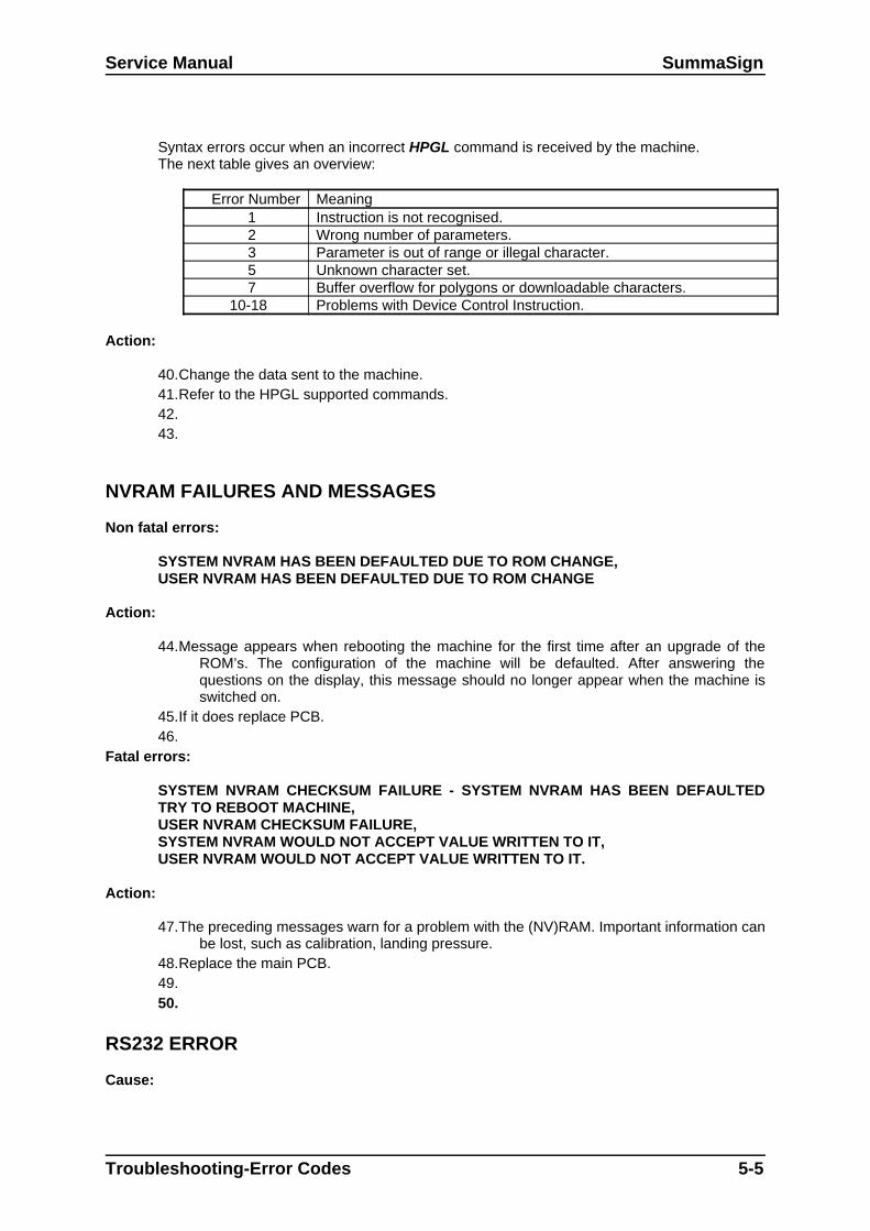
Service Manual SummaSign
Syntax errors occur when an incorrect HPGL command is received by the machine.The next table gives an overview:
Error Number Meaning 1 Instruction is not recognised. 2 Wrong number of parameters. 3 Parameter is out of range or illegal character. 5 Unknown character set. 7 Buffer overflow for polygons or downloadable characters.
10-18 Problems with Device Control Instruction.
Action:
40.Change the data sent to the machine. 41.Refer to the HPGL supported commands.42.43.
NVRAM FAILURES AND MESSAGES
Non fatal errors:
SYSTEM NVRAM HAS BEEN DEFAULTED DUE TO ROM CHANGE,USER NVRAM HAS BEEN DEFAULTED DUE TO ROM CHANGE
Action:
44.Message appears when rebooting the machine for the first time after an upgrade of theROM’s. The configuration of the machine will be defaulted. After answering thequestions on the display, this message should no longer appear when the machine isswitched on.
45.If it does replace PCB.46.
Fatal errors:
SYSTEM NVRAM CHECKSUM FAILURE - SYSTEM NVRAM HAS BEEN DEFAULTEDTRY TO REBOOT MACHINE,USER NVRAM CHECKSUM FAILURE,SYSTEM NVRAM WOULD NOT ACCEPT VALUE WRITTEN TO IT,USER NVRAM WOULD NOT ACCEPT VALUE WRITTEN TO IT.
Action:
47.The preceding messages warn for a problem with the (NV)RAM. Important information canbe lost, such as calibration, landing pressure.
48.Replace the main PCB.49.50.
RS232 ERROR
Cause:
Troubleshooting-Error Codes 5-5

SummaSign Service Manual
These errors can only happen when the RS232 test is being executed. A special loopbacktest cable is necessary to do this test. (This cable connects pin 2 to pin 3 and pin 7 to pin 8).Possible errors:
COULD NOT TRANSMIT DATACOULD NOT RECEIVE DATADATA RECEIVED DID NOT MATCH DATA TRANSMITTEDPARITY/FRAMING/OVERRUN ERRORCOULD NOT TOGGLE RTS HARDWARE HANDSHAKE LINE.
Action:
51.Make sure that the loopback connections have been made. 52.Check for bad contacts in the RS232 area on the PCB.53.Replace the main PCB.54.55.
INTERNAL ERRORS
Cause:
Happens when there is a Firmware problem or a problem with the main board (address busor data bus), the following list gives an overview:
Error Number Meaning1 bus error2 address error3 illegal instruction4 zero division5 chk instruction6 trapv instruction7 line 10108 line 1111
Action:56.This is an internal error. The cause of this error may be an unknown firmware problem in
the machine's EPROM’s. Do the internal confidence test. If this test is OK, check thedata sent to the machine.
57.Reflash the ROM’s on the main board. (change the ROM’s on the old type PCB)58.Replace the main PCB.
5-6 Troubleshooting-Error Codes

Service Manual SummaSign
59.
FLASHING ERRORS AND MESSAGES (ONLY ON NEW TYPE OF PCB)
60.Non fatal errors:
ERASING FLASH, PROGRAMMING,READING IN FLASH FILE
Action:
61.Message appears when the internal ROM’s are being reflashed. Just wait untill theoperation is done.
62.63.
Fatal errors:
ORDER ROMCOULD NOT ERASE FLASHCORRUPTED UPGRADE FILE
Action:
64.Those are fatal errors. The information in the internal ROM’s is not reliable any more.65.Order ROM’s and do an internal reflash.66.Change main PCB.67.
68.
ROM ERROR
Cause:
ROM’s are going bad.Action:
69.70.Reflash the ROM’s.71.Replace the main PCB.72.
RAM ERROR
Cause:
RAM’s are going bad.Action:
73.Replace the main PCB.
MACHINE UNABLE TO FIND THE KNIFE HOME POSITION
Cause:
The machine doesn’t find the home position for the tangential knife.
Troubleshooting-Error Codes 5-7
SummaSign Service Manual
Action:
74.Check whether the knife holder turns smoothly when the power is switched off. If not,something is wrong with the T-head. Replace the head or check the mechanical partsof the head.
75.Check the connection cable, which runs from the head to the PCB. 76.Check the machine with another head.77.Replace the flat cable which runs from the head to the PCB.78.Replace the main PCB.79.
MARKERS NOT SENSED PROPERLY
Cause:
The machine has trouble during its special load sequence.
Action:
80. Check whether there is dust on the sensor tip.81.Make sure that the markers are black on a white surface.82.Run the "OPTICAL SENSOR " test and use black and white vinyl to check the different
reflection levels.83.Make sure that the right settings are sent to the machine to sense the markers.84.Check the flat cable going from the head to the PCB.85.Should there still be problems, change OPOS.
86.
5-8 Troubleshooting-Error Codes

Figures 6-1
6. FIGURES
This section contains the detailed drawings of several assys of the SummaSign.There are no detailed drawings of the base, since the base (containing baseplateassys and the top beam assys) are considered as a whole and may never bedisassembled. If they should ever be taken apart (e.g. heavy transport damage), thenthe base has to be reassembled in the factory or by a CalComp technician).
Figures 6-1
1 391-344 assy motor with encoder2 391-809 assy motor without encoder3 ND5000-9694 screw M4x104 391-198 pulley+setscrew5 MB9124 belt 110T6 391-152
421-567pulley for 2 beltspulley for 1 belt
7 421-165 assy idler pulley8 ND5000-9643 standoff M4x409 ND5000-9683 standoff M4x30
10 ND5000-9769 spring

SummaSign Service Manual
6-2 Figures
1 391-132 plastic endplate right2 391-168
391-150assy display PRO-versionassy display
3 421-229 transfo4 391-344 assy motor with encoder5 391-346 assy power entry module6 391-342 assy switc pinch-roller7 MH0598 screw 6/328 MH0071 nut 6/329 ND5000-9175 screw M2x10
10 ND5000-9276 flatwasher M211 MH1323 screw 10/3212 MH0899 screw 6/3213 ND5000-0856 nut M314 ND5000-9265 lockwasher M3
15+16 391-361 assy grounding wire

Service Manual SummaSign
Figures 6-3
1 384-751 assy LCD module2 391-168 keyboard PRO series3 ND5000-9657 skiffy bus4 ND5000-9283 nylon washer 7x3.1x1.45 ND5000-9269 nut M26 ND5000-9358 Celrub 9x2mm7 384-682 LCD cable

SummaSign Service Manual
6-4 Figures
1 421-140 shaft2 MB0380 belt 150T3 391-315
391-555391-813
ass y-belt 610/750assy y-belt 1010assy y-belt 1300
4 ND5000-9151 PEMstud M35 391-935 assy final control board6 421-139 dbl pulley7 MH1317 E-ring

Service Manual SummaSign
Figures 6-5
1 391-100391-191
carriage plate 610/1010/1300carriage plate 750
2 391-365 assy, excentric shaft3 391-313 assy concentric shaft4 391-314 assy flatcable holder5 391-182 flatcable clamp6 ND5000-9667
ND5000-9668screw M2x4 (model 610/750)screw M2x5 (model 1010/1300
7 ND5000-9267 flatwasher M28 ND5000-9540 hexnut M49 ND5000-9231 lockwasher M4
10 ND5000-9620 washer 8x4.1x.311 ND5000-9602 screw M2x612 see prev. page13 ND5000-9587
ND5000-9604lockwasher M3screw M3
391-143 flatcable 610/750390-643 flatcable 1010/1300391-825 clear shield 915x25 (for 1010/1300)

SummaSign Service Manual
6-6 Figures
1 391-632 box tang head2 ND5000-9667 screw M2x43 ND5000-9267 flatwasher M24 391-655 assy motor tang head5 ND5000-9665 stand off M36 MH0624 washer7 ND5000-9663 stand off M28 391-662 pcb tang head9 391-657 assy main shaft
10 391-658 assy up/down (coil)11 391-627 nose piece (long)12 391-613 pulley13 MB9125 belt14 ND5000-9666 screw M2x415 391-656 assy wire encoder16 391-628 motor bracket17 391-661 magnet assy
1 391-201 assy up-down2 391-206 assy up-down support3 391-209 magnet assy4 391-213 bus mount assy5 391-216 pcb drag head6 391-215 guiding shaft7 ND5000-9586 roller cage 4/6.208 MR9002 o-ring 4x29 ND5000-9596 o-ring 4x1
10 ND5000-9382 truarc 3.211 ND5000-9585 roller cage 4/6/2.512 ND5000-9584 shaft 4x43.813 ND5000-9583 zackenring ZJ1014 ND5000-0856 nut M315 ND5000-9587 external lockwasher M316 ND5000-0328 flatwasher M317 ND5000-9582 spring .32x4.32x1918 ND5000-9581 screw M2.5x619 ND5000-9558 flatwasher M2.5
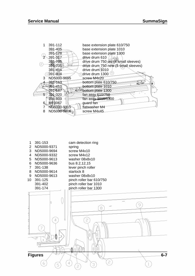
Service Manual SummaSign
Figures 6-7
1 391-112391-405391-178
base extension plate 610/750base extension plate 1010base extension plate 1300
2 391-317391-705391-735391-414391-804
drive drum 610drive drum 750 old (4 small sleeves)drive drum 750 new (5 small sleeves)drive drum 1010drive drum 1300
3 ND5000-9695 screw M4x204 391-113
391-410391-187
bottom plate 610/750bottom plate 1010bottom plate 1300
5 391-320391-803
fan assy 610/750fan assy 1010/1300
6 MF0067 guard fan7 ND5000-9315 flatwasher M48 ND5000-9606 screw M4x45
1 391-153 cam detection ring2 ND5000-9371 spring3 ND5000-9694 screw M4x104 ND5000-9332 screw M4x125 ND5000-9613 washer 08x8x106 ND5000-9636 bus 8.2,12,157 391-138 lever pinch roller8 ND5000-9614 starlock 89 ND5000-9613 washer 08x8x10
10 391-125391-402391-174
pinch roller bar 610/750pinch roller bar 1010pinch roller bar 1300

SummaSign Service Manual
6-8 Figures
1 391-147391-415391-751
rol 610/750rol 1010rol 1300
2 ND5000-9634 washer 8.2x25x2.53 391-130 distance bus 8x13x34 ND5000-9633 lockwasher M85 ND5000-9632 screw M8x166 ND5000-9499 corex cap7 ND5000-9631 screw M8x16 DIN 9128 391-183 brake9 391-171 roller guiding
1 391-171 roller guiding2 ND5000-9651 O-ring dia 48x53 ND5000-9698 O-ring dia 52x34 391-183 brake

Service Manual SummaSign
Figures 6-9
1 motor encoder2 red on +3 black on -4 connector 5pin5 tie-wrap holder6 tie-wrap7 capacitor MC1697
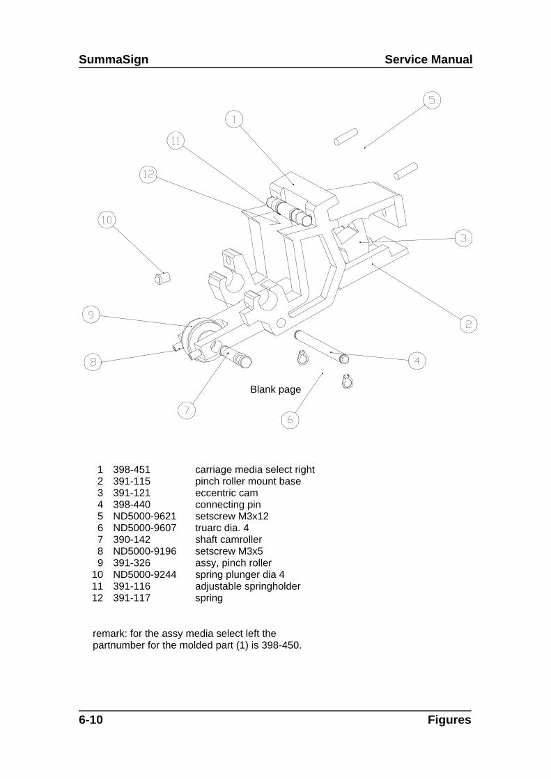
SummaSign Service Manual
6-10 Figures
1 398-451 carriage media select right2 391-115 pinch roller mount base3 391-121 eccentric cam4 398-440 connecting pin5 ND5000-9621 setscrew M3x126 ND5000-9607 truarc dia. 47 390-142 shaft camroller8 ND5000-9196 setscrew M3x59 391-326 assy, pinch roller
10 ND5000-9244 spring plunger dia 411 391-116 adjustable springholder12 391-117 spring
remark: for the assy media select left thepartnumber for the molded part (1) is 398-450.
Blank page
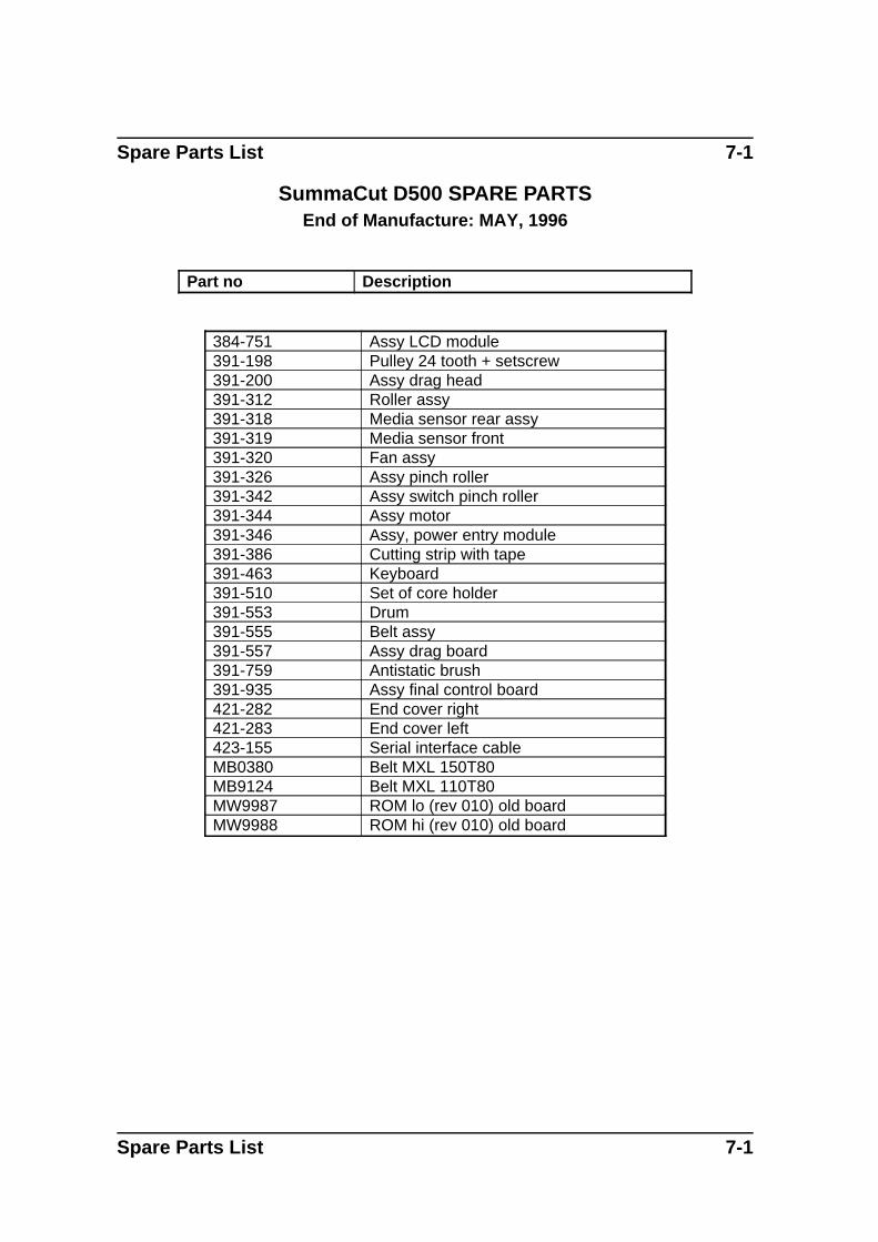
Spare Parts List 7-1
SummaCut D500 SPARE PARTSEnd of Manufacture: MAY, 1996
Part no Description
384-751 Assy LCD module391-198 Pulley 24 tooth + setscrew391-200 Assy drag head391-312 Roller assy391-318 Media sensor rear assy391-319 Media sensor front391-320 Fan assy391-326 Assy pinch roller391-342 Assy switch pinch roller391-344 Assy motor391-346 Assy, power entry module391-386 Cutting strip with tape391-463 Keyboard391-510 Set of core holder391-553 Drum391-555 Belt assy391-557 Assy drag board391-759 Antistatic brush391-935 Assy final control board421-282 End cover right421-283 End cover left423-155 Serial interface cableMB0380 Belt MXL 150T80MB9124 Belt MXL 110T80MW9987 ROM lo (rev 010) old boardMW9988 ROM hi (rev 010) old board
Spare Parts List 7-1

Spare Parts List 7-2
SummaSign D610 SPARE PARTSEnd of Manufacture: April, 1996
Part no. Description
384-682 LCD cable384-751 Assy LCD module391-117 Spring391-143 Flat cable391-144 Cutting Strip 84 cm391-150 Display keyboard 391-200 Assy, drag head391-222 Cover head391-224 Knife, offset 0.45391-227 Lock nut knife holder391-311 Centron drag & tang
board391-312 Roller assy391-315 Belt assy391-317 Drive drum, Assy391-318 Media sensor rear assy391-319 Media sensor front assy391-320 Fan assy391-326 Assy, pinch roller391-332 Knife holder assy391-342 Assy, switch pinch roller391-344 Assy, motor391-346 Power entry module391-366 Endcover right391-367 Endcover left391-386 Cutting strip with tape391-510 Set of Core holders391-935 Assy, final control boardMB0380 Belt 150T80MB9124 Belt 110T80MW9987 Rom U24 rev 010MW9988 Rom U17 rev 010ND5000-9622 Knob coreholderND5000-9646 O-ring
ACCESSORIES ANDCONSUMABLES
391-146 Manual Cut-Off Razor Blades(set of 10)
391-332 Standard Knife Holder
391-348 Razor Blade & Holder391-358 Sandblast Knife blade391-360 Standard Knife Blade391-363 Sandblast Knife Holder391-400 Cutter Stand (optional)391-500 Flange for Roll Media (single)391-510 Flanges for Roll Media (pair)391-595 Pouncing Tool Drag391-785 OPOS Field upgrade kit Drag423-155 Serial Interface KitMC1184 Power Supply Cables European
typeMC3545 Power Supply Cables American
typeMI9990 User’s Manual
Spare Parts List 7-2

Service Manual SummaSign
SummaSign D610 PRO SPARE PARTSEnd of Manufacture: Current
Part no. Description
384-682 LCD cable384-751 Assy LCD module391-117 Spring391-143 Flat cable391-144 Cutting Strip 84 cm391-168 Display keyboard 391-200 Assy, drag head391-222 Cover head391-224 Knife, offset 0.45391-227 Lock nut knife holder391-281 Nameplate D610 Pro391-312 Roller assy391-315 Belt assy391-317 Drive drum, Assy391-318 Media sensor rear
assy391-319 Media sensor front
assy391-320 Fan assy391-326 Assy, pinch roller391-332 Knife holder assy391-342 Assy, switch pinch
roller391-344 Assy, motor391-346 Power entry module391-366 Endcover right391-367 Endcover left391-386 Cutting strip with tape391-510 Core holders391-935 Assy, final control
boardMB0380 Belt 150T80MB9124 Belt 110T80ND5000-9622 Knob coreholderND5000-9646 O-ringND5000-9769 Y belt spring
Accessories and consumables
391-146 Manual Cut-Off RazorBlades (set of 10)
391-332 Standard Knife Holder
391-348 Razor Blade & Holder391-358 Sandblast Knife blade391-360 Standard Knife Blade391-363 Sandblast Knife Holder391-400 Cutter Stand (optional)391-500 Flange for Roll Media
(single)391-510 Flanges for Roll Media
(pair)391-595 Pouncing Tool391-785 OPOS Field upgrade kit
Drag423-155 Serial Interface KitMC1184 Power Supply Cables
European typeMC3545 Power Supply Cables
American typeMI9020 User’s Manual + Software
on CD
Spare Parts List 7-3
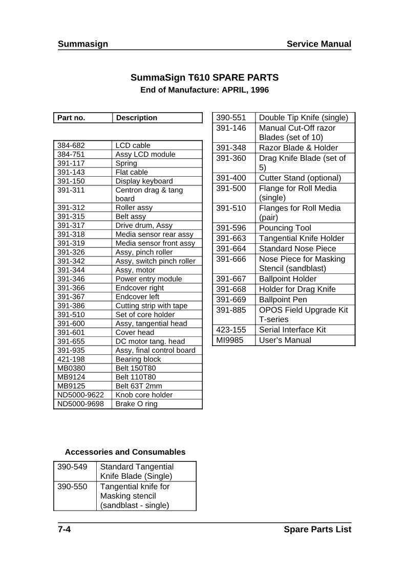
Summasign Service Manual
SummaSign T610 SPARE PARTSEnd of Manufacture: APRIL, 1996
Part no. Description
384-682 LCD cable384-751 Assy LCD module391-117 Spring391-143 Flat cable391-150 Display keyboard 391-311 Centron drag & tang
board391-312 Roller assy391-315 Belt assy391-317 Drive drum, Assy391-318 Media sensor rear assy391-319 Media sensor front assy391-326 Assy, pinch roller391-342 Assy, switch pinch roller391-344 Assy, motor391-346 Power entry module391-366 Endcover right391-367 Endcover left391-386 Cutting strip with tape391-510 Set of core holder391-600 Assy, tangential head391-601 Cover head391-655 DC motor tang. head391-935 Assy, final control board421-198 Bearing blockMB0380 Belt 150T80MB9124 Belt 110T80MB9125 Belt 63T 2mmND5000-9622 Knob core holderND5000-9698 Brake O ring
Accessories and Consumables
390-549 Standard TangentialKnife Blade (Single)
390-550 Tangential knife forMasking stencil(sandblast - single)
390-551 Double Tip Knife (single)391-146 Manual Cut-Off razor
Blades (set of 10)391-348 Razor Blade & Holder391-360 Drag Knife Blade (set of
5)391-400 Cutter Stand (optional)391-500 Flange for Roll Media
(single)391-510 Flanges for Roll Media
(pair)391-596 Pouncing Tool391-663 Tangential Knife Holder391-664 Standard Nose Piece391-666 Nose Piece for Masking
Stencil (sandblast)391-667 Ballpoint Holder391-668 Holder for Drag Knife391-669 Ballpoint Pen391-885 OPOS Field Upgrade Kit
T-series423-155 Serial Interface KitMI9985 User’s Manual
7-4 Spare Parts List

Service Manual SummaSign
SummaSign T610 PRO SPARE PARTSEnd of Manufacture: Current
Part no. Description
384-682 LCD cable384-751 Assy LCD module391-117 Spring391-143 Flat cable391-168 Display keyboard 391-282 Nameplate T610 Pro391-312 Roller assy391-315 Belt assy391-317 Drive drum, Assy391-318 Media sensor rear assy391-319 Media sensor front assy391-326 Assy, pinch roller391-342 Assy, switch pinch roller391-344 Assy, motor391-346 Power entry module391-366 Endcover right391-367 Endcover left391-386 Cutting strip with tape391-510 Set of core holder391-600 Assy, tangential head391-601 Cover head391-655 DC motor tang. head391-935 Assy, final control board421-198 Bearing blockMB0380 Belt 150T80MB9124 Belt 110T80MB9125 Belt 63T 2mmND5000-9622 Knob core holderND5000-9698 Brake O ringND5000-9769 Y belt spring
Accessories and Consumables
390-549 Standard Tangential KnifeBlade (Single)
390-550 Tangential knife forMasking stencil (sandblast)
390-551 Double Tip Knife (single)391-146 Manual Cut-Off razor
Blades (set of 10)391-348 Razor Blade & Holder391-360 Drag Knife Blade (set of 5)391-400 Cutter Stand (optional)391-500 Flange for Roll Media
(single)391-510 Flanges for Roll Media
(pair)391-596 Pouncing Tool391-663 Tangential Knife Holder391-664 Standard Nose Piece391-666 Nose Piece for Masking
Stencil (sandblast)391-667 Ballpoint Holder391-668 Holder for Drag Knife391-669 Ballpoint Pen391-885 OPOS Field Upgrade Kit T-
series423-155 Serial Interface KitMD9020 User’s Manual on CD
Spare Parts List 7-5

Summasign Service Manual
SummaSign D750 SPARE PARTSEnd of Manufacture: April, 1996
Part no. Description
384-682 LCD cable384-751 Assy LCD module391-117 Spring391-143 Flat cable391-144 Cutting Strip 84 cm391-150 Display keyboard 391-200 Assy, drag head391-222 Cover head391-224 Knife, offset 0.45391-227 Lock nut knife holder391-311 Centron drag & tang
board391-312 Roller assy391-315 Belt assy391-318 Media sensor rear assy391-319 Media sensor front assy391-320 Fan assy391-326 Assy, pinch roller391-332 Knife holder assy391-342 Assy, switch pinch roller391-344 Assy, motor391-346 Power entry module391-366 Endcover right391-367 Endcover left391-386 Cutting strip with tape391-510 Set of Core holders391-705 Drive drum, Assy391-935 Assy, final control boardMB0380 Belt 150T80MB9124 Belt 110T80MW9987 Rom U24 rev 010MW9988 Rom U17 rev 010ND5000-9622 Knob coreholderND5000-9646 O-ring
Accessories and consumables
391-146 Manual Cut-Off Razor Blades(set of 10)
391-332 Standard Knife Holder391-348 Razor Blade & Holder391-358 Sandblast Knife blade391-360 Standard Knife Blade391-363 Sandblast Knife Holder391-400 Cutter Stand (optional)391-500 Flange for Roll Media (single)391-510 Flanges for Roll Media (pair)391-595 Pouncing Tool Drag391-785 OPOS Field upgrade kit Drag423-155 Serial Interface KitMC1184 Power Supply Cables
European typeMC3545 Power Supply Cables
American typeMI9990 User’s Manual
7-6 Spare Parts List
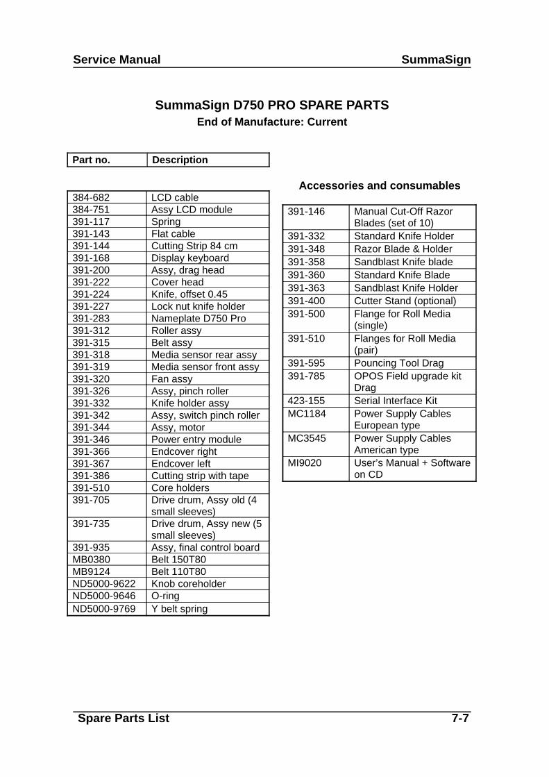
Service Manual SummaSign
SummaSign D750 PRO SPARE PARTSEnd of Manufacture: Current
Part no. Description
384-682 LCD cable384-751 Assy LCD module391-117 Spring391-143 Flat cable391-144 Cutting Strip 84 cm391-168 Display keyboard 391-200 Assy, drag head391-222 Cover head391-224 Knife, offset 0.45391-227 Lock nut knife holder391-283 Nameplate D750 Pro391-312 Roller assy391-315 Belt assy391-318 Media sensor rear assy391-319 Media sensor front assy391-320 Fan assy391-326 Assy, pinch roller391-332 Knife holder assy391-342 Assy, switch pinch roller391-344 Assy, motor391-346 Power entry module391-366 Endcover right391-367 Endcover left391-386 Cutting strip with tape391-510 Core holders391-705 Drive drum, Assy old (4
small sleeves)391-735 Drive drum, Assy new (5
small sleeves)391-935 Assy, final control boardMB0380 Belt 150T80MB9124 Belt 110T80ND5000-9622 Knob coreholderND5000-9646 O-ringND5000-9769 Y belt spring
Accessories and consumables
391-146 Manual Cut-Off RazorBlades (set of 10)
391-332 Standard Knife Holder391-348 Razor Blade & Holder391-358 Sandblast Knife blade391-360 Standard Knife Blade391-363 Sandblast Knife Holder391-400 Cutter Stand (optional)391-500 Flange for Roll Media
(single)391-510 Flanges for Roll Media
(pair)391-595 Pouncing Tool Drag391-785 OPOS Field upgrade kit
Drag423-155 Serial Interface KitMC1184 Power Supply Cables
European typeMC3545 Power Supply Cables
American typeMI9020 User’s Manual + Software
on CD
Spare Parts List 7-7

Summasign Service Manual
SummaSign T750 SPARE PARTSEnd of Manufacture: APRIL, 1996
Part no. Description
384-682 LCD cable384-751 Assy LCD module391-117 Spring391-143 Flat cable391-150 Display keyboard 391-311 Centron drag & tang
board391-312 Roller assy391-315 Belt assy391-318 Media sensor rear assy391-319 Media sensor front assy391-326 Assy, pinch roller391-342 Assy, switch pinch roller391-344 Assy, motor391-346 Power entry module391-366 Endcover right391-367 Endcover left391-386 Cutting strip with tape391-510 Set of core holders391-600 Assy, tangential head391-601 Cover head391-655 DC motor tang. head391-705 Drive drum, Assy391-935 Assy, final control board421-198 Bearing blockMB0380 Belt 150T80MB9124 Belt 110T80MB9125 Belt 63T 2mmND5000-9622 Knob core holderND5000-9698 Brake O ring
Accessories and Consumables
390-549 Standard Tangential KnifeBlade (Single)
390-550 Tangential knife forMasking stencil (sandblast- single)
390-551 Double Tip Knife (single)
391-146 Manual Cut-Off razorBlades (set of 10)
391-348 Razor Blade & Holder391-360 Drag Knife Blade (set of 5)391-400 Cutter Stand (optional)391-500 Flange for Roll Media
(single)391-510 Flanges for Roll Media
(pair)391-596 Pouncing Tool391-663 Tangential Knife Holder391-664 Standard Nose Piece391-666 Nose Piece for Masking
Stencil (sandblast)391-667 Ballpoint Holder391-668 Holder for Drag Knife391-669 Ballpoint Pen391-885 OPOS Field Upgrade Kit
T-series423-155 Serial Interface KitMI9985 User’s Manual
7-8 Spare Parts List

Service Manual SummaSign
SummaSign T750 PRO SPARE PARTSEnd of Manufacture: Current
Part no. Description
384-682 LCD cable384-751 Assy LCD module391-117 Spring391-143 Flat cable391-168 Display keyboard 391-224 Knife, offset 0.45391-284 Nameplate T750 Pro391-312 Roller assy391-315 Belt assy391-318 Media sensor rear assy391-319 Media sensor front assy391-326 Assy, pinch roller391-342 Assy, switch pinch roller391-344 Assy, motor391-346 Power entry module391-366 Endcover right391-367 Endcover left391-386 Cutting strip with tape391-510 Core holder391-600 Assy, tangential head391-601 Cover head391-655 DC motor tang. head391-705 Drive drum, Assy old (4
small sleeves)391-735 Drive drum, Assy new (5
small sleeves)391-935 Assy, final control board421-198 Bearing blockMB0380 Belt 150T80MB9124 Belt 110T80MB9125 Belt 63T 2mmND5000-9622 Knob core holderND5000-9698 Brake O ring
ND5000-9769 Y belt spring
Accessories and Consumables
390-549 Standard Tangential KnifeBlade (Single)
390-550 Tangential knife forMasking stencil(sandblast)
390-551 Double Tip Knife (single)391-146 Manual Cut-Off razor
Blades (set of 10)391-348 Razor Blade & Holder391-360 Drag Knife Blade (set of 5)391-400 Cutter Stand (optional)391-500 Flange for Roll Media
(single)391-510 Flanges for Roll Media
(pair)391-596 Pouncing Tool391-663 Tangential Knife Holder391-664 Standard Nose Piece391-666 Nose Piece for Masking
Stencil (sandblast)391-667 Ballpoint Holder391-668 Holder for Drag Knife391-669 Ballpoint Pen391-885 OPOS Field Upgrade Kit
T-series423-155 Serial Interface KitMD9020 User
’s Manual on CD
Spare Parts List 7-9

Summasign Service Manual
SummaSign D1010 SPARE PARTSEnd of Manufacture: April, 1996
Part no. Description
384-682 LCD cable384-751 Assy LCD module390-643 Flat cable391-117 Spring391-150 Display keyboard 391-200 Assy, drag head391-222 Cover head391-224 Knife, offset 0.45391-227 Lock nut knife holder391-311 Centron drag & tang
board391-312 Roller assy391-318 Media sensor rear assy391-319 Media sensor front assy391-326 Assy, pinch roller391-332 Knife holder assy391-342 Assy, switch pinch roller391-344 Assy, motor391-346 Power entry module391-366 Endcover right391-367 Endcover left391-414 Drive drum, Assy391-421 Belt assy391-510 Set of Core holders391-803 Fan assy391-809 Assy motor without
encoder391-886 Cutting strip with tape391-935 Assy, final control board398-198 Pulley 24 tooth +
setscrewMB0380 Belt 150T80
MB9124 Belt 110T80MW9987 Rom U24 rev 010MW9988 Rom U17 rev 010ND5000-9622 Knob coreholderND5000-9646 O-ring
Accessories and consumables
391-146 Manual Cut-Off RazorBlades (set of 10)
391-332 Standard Knife Holder391-348 Razor Blade & Holder391-358 Sandblast Knife blade391-360 Standard Knife Blade391-363 Sandblast Knife Holder391-500 Flange for Roll Media
(single)391-510 Flanges for Roll Media (pair)391-595 Pouncing Tool391-785 OPOS Field upgrade kit
Drag391-850 Cutter Stand 423-155 Serial Interface KitMC1184 Power Supply Cables
European typeMC3545 Power Supply Cables
American typeMI9990 User’s Manual
7-10 Spare Parts List

Service Manual SummaSign
SummaSign D1010 PRO SPARE PARTSEnd of Manufacture: Current
Part no. Description
384-682 LCD cable384-751 Assy LCD module390-643 Flat cable391-117 Spring391-168 Display keyboard 391-200 Assy, drag head391-222 Cover head391-224 Knife, offset 0.45391-227 Lock nut knife holder391-285 Nameplate D1010 Pro391-312 Roller assy391-318 Media sensor rear assy391-319 Media sensor front assy391-326 Assy, pinch roller391-332 Knife holder assy391-342 Assy, switch pinch roller391-344 Assy, motor391-346 Power entry module391-366 Endcover right391-367 Endcover left391-414 Drive drum, Assy391-421 Belt assy391-510 Core holders391-803 Fan assy391-886 Cutting strip with tape391-935 Assy, final control boardMB0380 Belt 150T80MB9124 Belt 110T80ND5000-9622 Knob coreholderND5000-9646 O-ringND5000-9769 Y belt spring
Accessories and consumables
391-146 Manual Cut-Off RazorBlades (set of 10)
391-332 Standard Knife Holder391-348 Razor Blade & Holder391-358 Sandblast Knife blade391-360 Standard Knife Blade391-363 Sandblast Knife Holder391-500 Flange for Roll Media
(single)391-510 Flanges for Roll Media
(pair)391-595 Pouncing Tool391-785 OPOS Field upgrade kit
Drag391-850 Cutter Stand (optional)423-155 Serial Interface KitMC1184 Power Supply Cables
European typeMC3545 Power Supply Cables
American typeMI9020 User’s Manual + Software
on CD
Spare Parts List 7-11
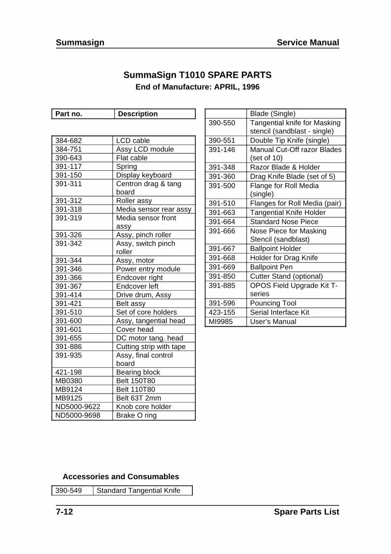
Summasign Service Manual
SummaSign T1010 SPARE PARTSEnd of Manufacture: APRIL, 1996
Part no. Description
384-682 LCD cable384-751 Assy LCD module390-643 Flat cable391-117 Spring391-150 Display keyboard 391-311 Centron drag & tang
board391-312 Roller assy391-318 Media sensor rear assy391-319 Media sensor front
assy391-326 Assy, pinch roller391-342 Assy, switch pinch
roller391-344 Assy, motor391-346 Power entry module391-366 Endcover right391-367 Endcover left391-414 Drive drum, Assy391-421 Belt assy391-510 Set of core holders391-600 Assy, tangential head391-601 Cover head391-655 DC motor tang. head391-886 Cutting strip with tape391-935 Assy, final control
board421-198 Bearing blockMB0380 Belt 150T80MB9124 Belt 110T80MB9125 Belt 63T 2mmND5000-9622 Knob core holderND5000-9698 Brake O ring
Accessories and Consumables
390-549 Standard Tangential Knife
Blade (Single)390-550 Tangential knife for Masking
stencil (sandblast - single)390-551 Double Tip Knife (single)391-146 Manual Cut-Off razor Blades
(set of 10)391-348 Razor Blade & Holder391-360 Drag Knife Blade (set of 5)391-500 Flange for Roll Media
(single)391-510 Flanges for Roll Media (pair)391-663 Tangential Knife Holder391-664 Standard Nose Piece391-666 Nose Piece for Masking
Stencil (sandblast)391-667 Ballpoint Holder391-668 Holder for Drag Knife391-669 Ballpoint Pen391-850 Cutter Stand (optional)391-885 OPOS Field Upgrade Kit T-
series391-596 Pouncing Tool423-155 Serial Interface KitMI9985 User’s Manual
7-12 Spare Parts List

Service Manual SummaSign
Spare Parts List 7-13
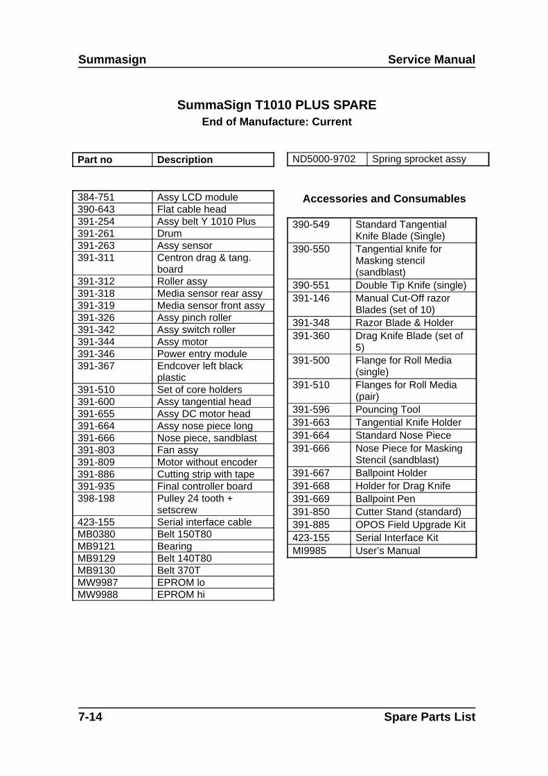
Summasign Service Manual
SummaSign T1010 PLUS SPAREEnd of Manufacture: Current
Part no Description
384-751 Assy LCD module390-643 Flat cable head391-254 Assy belt Y 1010 Plus391-261 Drum391-263 Assy sensor391-311 Centron drag & tang.
board391-312 Roller assy391-318 Media sensor rear assy391-319 Media sensor front assy391-326 Assy pinch roller391-342 Assy switch roller391-344 Assy motor391-346 Power entry module391-367 Endcover left black
plastic391-510 Set of core holders391-600 Assy tangential head391-655 Assy DC motor head391-664 Assy nose piece long391-666 Nose piece, sandblast391-803 Fan assy391-809 Motor without encoder391-886 Cutting strip with tape391-935 Final controller board398-198 Pulley 24 tooth +
setscrew423-155 Serial interface cableMB0380 Belt 150T80MB9121 BearingMB9129 Belt 140T80MB9130 Belt 370TMW9987 EPROM loMW9988 EPROM hi
ND5000-9702 Spring sprocket assy
Accessories and Consumables
390-549 Standard TangentialKnife Blade (Single)
390-550 Tangential knife forMasking stencil(sandblast)
390-551 Double Tip Knife (single)391-146 Manual Cut-Off razor
Blades (set of 10)391-348 Razor Blade & Holder391-360 Drag Knife Blade (set of
5)391-500 Flange for Roll Media
(single)391-510 Flanges for Roll Media
(pair)391-596 Pouncing Tool391-663 Tangential Knife Holder391-664 Standard Nose Piece391-666 Nose Piece for Masking
Stencil (sandblast)391-667 Ballpoint Holder391-668 Holder for Drag Knife391-669 Ballpoint Pen391-850 Cutter Stand (standard)391-885 OPOS Field Upgrade Kit423-155 Serial Interface KitMI9985 User’s Manual
7-14 Spare Parts List
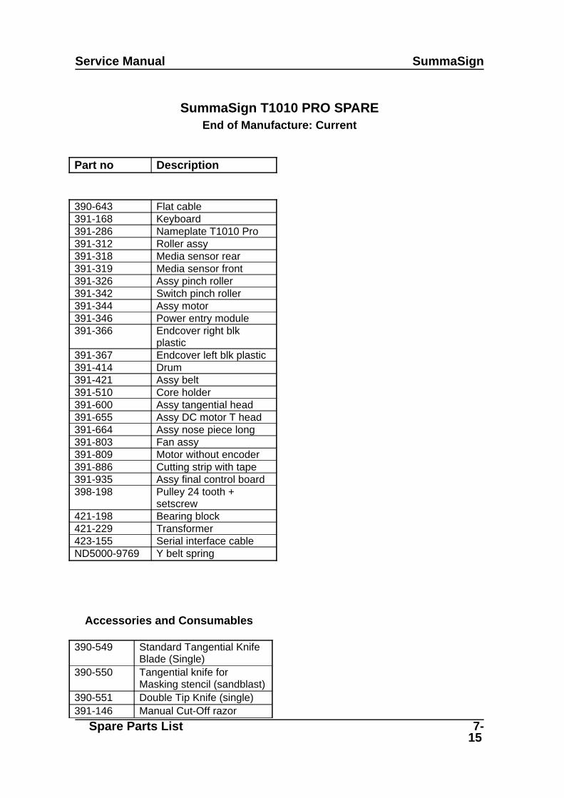
Service Manual SummaSign
SummaSign T1010 PRO SPAREEnd of Manufacture: Current
Part no Description
390-643 Flat cable391-168 Keyboard391-286 Nameplate T1010 Pro391-312 Roller assy391-318 Media sensor rear391-319 Media sensor front391-326 Assy pinch roller391-342 Switch pinch roller391-344 Assy motor391-346 Power entry module391-366 Endcover right blk
plastic391-367 Endcover left blk plastic391-414 Drum391-421 Assy belt391-510 Core holder391-600 Assy tangential head391-655 Assy DC motor T head391-664 Assy nose piece long391-803 Fan assy391-809 Motor without encoder391-886 Cutting strip with tape391-935 Assy final control board398-198 Pulley 24 tooth +
setscrew421-198 Bearing block421-229 Transformer423-155 Serial interface cableND5000-9769 Y belt spring
Accessories and Consumables
390-549 Standard Tangential KnifeBlade (Single)
390-550 Tangential knife forMasking stencil (sandblast)
390-551 Double Tip Knife (single)391-146 Manual Cut-Off razor
Spare Parts List 7-15

Summasign Service Manual
7-16 Spare Parts List

Service Manual SummaSign
Blades (set of 10)391-348 Razor Blade & Holder391-360 Drag Knife Blade (set of 5)391-500 Flange for Roll Media
(single)391-510 Flanges for Roll Media
(pair)391-596 Pouncing Tool391-663 Tangential Knife Holder391-664 Standard Nose Piece391-666 Nose Piece for Masking
Stencil (sandblast)391-667 Ballpoint Holder391-668 Holder for Drag Knife391-669 Ballpoint Pen391-850 Cutter Stand (standard)391-885 OPOS Field Upgrade Kit423-155 Serial Interface KitMD9020 User’s Manual
Spare Parts List 7-17

Summasign Service Manual
SummaSign D1300 SPARE PARTSEnd of Manufacture: APRIL, 1996
Part no. Description
384-682 LCD cable384-751 Assy LCD module390-643 Flat cable391-117 Spring391-150 Display keyboard 391-200 Assy, drag head391-222 Cover head391-224 Knife, offset 0.45391-311 Centron drag & tang. board391-312 Roller assy391-318 Media sensor rear assy391-319 Media sensor front assy391-320 Fan assy391-326 Assy, pinch roller391-332 Knife holder assy391-342 Assy, switch pinch roller391-344 Assy, motor391-346 Power entry module391-366 Endcover right391-367 Endcover left391-510 Set of core holders391-803 Fan assy391-804 Drive drum, Assy391-809 Assy motor without
encoder391-813 Belt assy391-860 Assy driver PCB 1300391-886 Cutting strip with tape391-935 Assy, final control board421-198 Bearing blockMB0380 Belt timingMB9124 Belt 110MW9955 Rom U24MW9965 Rom U17
Accessories and consumables
391-146 Manual Cut-Off RazorBlades (set of 10)
391-332 Standard Knife Holder391-348 Razor Blade & Holder391-358 Sandblast Knife blade391-360 Standard Knife Blade391-363 Sandblast Knife Holder391-500 Flange for Roll Media
(single)391-510 Flanges for Roll Media
(pair)391-595 Pouncing Tool391-785 OPOS Field Upgrade
Kit391-850 Cutter Stand423-155 Serial Interface KitMC1184 Power Supply CablesMI9990 User’s Manual
7-18 Spare Parts List
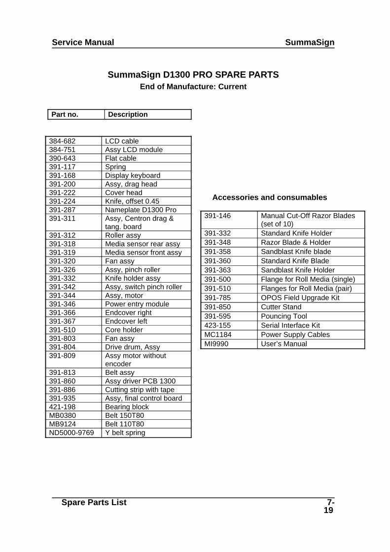
Service Manual SummaSign
SummaSign D1300 PRO SPARE PARTSEnd of Manufacture: Current
Part no. Description
384-682 LCD cable384-751 Assy LCD module390-643 Flat cable391-117 Spring391-168 Display keyboard 391-200 Assy, drag head391-222 Cover head391-224 Knife, offset 0.45391-287 Nameplate D1300 Pro391-311 Assy, Centron drag &
tang. board391-312 Roller assy391-318 Media sensor rear assy391-319 Media sensor front assy391-320 Fan assy391-326 Assy, pinch roller391-332 Knife holder assy391-342 Assy, switch pinch roller391-344 Assy, motor391-346 Power entry module391-366 Endcover right391-367 Endcover left391-510 Core holder391-803 Fan assy391-804 Drive drum, Assy391-809 Assy motor without
encoder391-813 Belt assy391-860 Assy driver PCB 1300391-886 Cutting strip with tape391-935 Assy, final control board421-198 Bearing blockMB0380 Belt 150T80MB9124 Belt 110T80ND5000-9769 Y belt spring
Accessories and consumables
391-146 Manual Cut-Off Razor Blades(set of 10)
391-332 Standard Knife Holder391-348 Razor Blade & Holder391-358 Sandblast Knife blade391-360 Standard Knife Blade391-363 Sandblast Knife Holder391-500 Flange for Roll Media (single)391-510 Flanges for Roll Media (pair)391-785 OPOS Field Upgrade Kit391-850 Cutter Stand391-595 Pouncing Tool423-155 Serial Interface KitMC1184 Power Supply CablesMI9990 User’s Manual
Spare Parts List 7-19

Summasign Service Manual
SummaSign T1300 SPARE PARTSEnd of Manufacture: APRIL, 1996
Part no. Description
384-571 Assy LCD module384-682 LCD cable390-643 Flat cable391-150 Display keyboard 391-311 Centron drag & tang. board391-312 Roller assy391-318 Media sensor rear assy391-319 Media sensor front assy391-326 Assy, pinch roller391-342 Assy, swit ch pinch roller391-344 Assy, motor391-346 Power entry module391-366 Endcover right391-367 Endcover left391-510 Set of core holders391-600 Assy, tangential head391-601 Cover head391-655 DC motor tang. head391-803 Fan assy391-804 Drive drum, Assy391-809 Motor without encoder391-813 Belt assy D1300391-860 Assy driver PCB 1300391-886 Cutting strip with tape391-935 Final control board T1300MB0380 Belt 150T80MB9124 Belt 110T80MB9125 Belt 63T 2mmMW9987 Rom U24MW9988 Rom U17
Accessories and Consumables
390-549 Standard Tangential KnifeBlade (Single)
390-550 Tangential knife forMasking stencil (sandblast)
390-551 Double Tip Knife (single)391-146 Manual Cut-Off razor
Blades (set of 10)391-348 Razor Blade & Holder
391-360 Drag Knife Blade (set of 5)391-500 Flange for Roll Media
(single)391-510 Flanges for Roll Media
(pair)391-596 Pouncing Tool391-663 Tangential Knife Holder391-664 Standard Nose Piece391-666 Nose Piece for Masking
Stencil (sandblast)391-667 Ballpoint Holder391-668 Holder for Drag Knife391-669 Ballpoint Pen391-850 Cutter Stand (standard)391-885 OPOS Field Upgrade Kit423-155 Serial Interface KitMI9985 User’s Manual
7-20 Spare Parts List
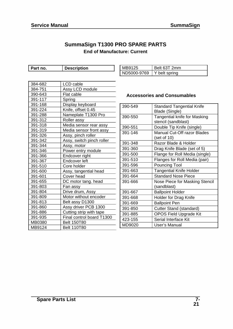
Service Manual SummaSign
SummaSign T1300 PRO SPARE PARTSEnd of Manufacture: Current
Part no. Description
384-682 LCD cable384-751 Assy LCD module390-643 Flat cable391-117 Spring391-168 Display keyboard 391-224 Knife, offset 0.45391-288 Nameplate T1300 Pro391-312 Roller assy391-318 Media sensor rear assy391-319 Media sensor front assy391-326 Assy, pinch roller391-342 Assy, switch pinch roller391-344 Assy, motor391-346 Power entry module391-366 Endcover right391-367 Endcover left391-510 Core holder391-600 Assy, tangential head391-601 Cover head391-655 DC motor tang. head391-803 Fan assy391-804 Drive drum, Assy391-809 Motor without encoder391-813 Belt assy D1300391-860 Assy driver PCB 1300391-886 Cutting strip with tape391-935 Final control board T1300MB0380 Belt 150T80MB9124 Belt 110T80
MB9125 Belt 63T 2mmND5000-9769 Y belt spring
Accessories and Consumables
390-549 Standard Tangential KnifeBlade (Single)
390-550 Tangential knife for Maskingstencil (sandblast)
390-551 Double Tip Knife (single)391-146 Manual Cut-Off razor Blades
(set of 10)391-348 Razor Blade & Holder391-360 Drag Knife Blade (set of 5)391-500 Flange for Roll Media (single)391-510 Flanges for Roll Media (pair)391-596 Pouncing Tool391-663 Tangential Knife Holder391-664 Standard Nose Piece391-666 Nose Piece for Masking Stencil
(sandblast)391-667 Ballpoint Holder391-668 Holder for Drag Knife391-669 Ballpoint Pen391-850 Cutter Stand (standard)391-885 OPOS Field Upgrade Kit423-155 Serial Interface KitMD9020 User’s Manual
Spare Parts List 7-21

CHANGING THE O-RING ON THEBRAKE
To remove the left-hand cover, proceed as follows:
1. Remove the five screws (four long screws and a short screw) holding the left-hand cover in place.Three are located at the front, one at the rear and one at the bottom (it is not necessary to turnthe unit upside down to remove the bottom screw). Pay close attention to where each of thescrews goes. They should be returned to their original location when re-installed.
2. Gently tap the top of the cover.
3. Remove the cover. (fig1)
fig14. Unscrew the black bolt situated on place 1 in fig 2.
5. Gently lift the lift and slide the two bushing which normaly hold the flanges.
6. Take the o-ring(s) of the brake (black part on the end of theroll).
7. Put new o-rings on it.
fig2
To re-install, proceed in the reverse order of removal. Make sure to firmly tighten all screws.

REMOVING THE LEFT HAND COVER
To remove the left-hand cover, proceed as follows:
1. Remove the five screws holding the left cover in place. Two are located at the back, one at the top, oneat the bottom and in front just under the baseplate Pay attention to where each of the screw goes. Theyshould be returned to their original location when re-installed.
2. Gently tap the top of the cover.
3. Be careful not to tear the flatcable off the keyboard
4. Remove the connector. Play close attention to where the connector of the flatcable goes. It should bereturned to its original location (top three pins uncovered)
5. Remove the cover.
To re-install, proceed in the reverse order of removal. Make sure to firmly tighten all screws.
! CAUTION
Make sure that you do not jam any wires between the cover and the sideplate as this may cause considerable damage.
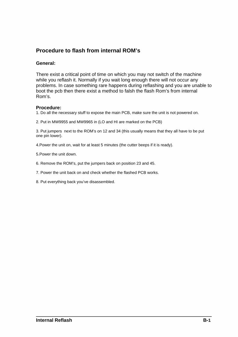
Procedure to flash from internal ROM’s
General:
There exist a critical point of time on which you may not switch of the machinewhile you reflash it. Normally if you wait long enough there will not occur anyproblems. In case something rare happens during reflashing and you are unable toboot the pcb then there exist a method to falsh the flash Rom’s from internalRom’s.
Procedure:1. Do all the necessary stuff to expose the main PCB, make sure the unit is not powered on.
2. Put in MW9955 and MW9965 in (LO and HI are marked on the PCB)
3. Put jumpers next to the ROM’s on 12 and 34 (this usually means that they all have to be putone pin lower).
4.Power the unit on, wait for at least 5 minutes (the cutter beeps if it is ready).
5.Power the unit down.
6. Remove the ROM’s, put the jumpers back on position 23 and 45.
7. Power the unit back on and check whether the flashed PCB works.
8. Put everything back you’ve disassembled.
Internal Reflash B-1

APPENDIX A
Removal of the left side
General
Under normal conditions, it is not advisable to remove the left side because the base is assembledwith different fixtures and molds to ensure straightness of the base. However in someunexceptional conditions, it might be necessary to do so. The following procedure is a guideline todo so, but does not guarentee succes. Some unforseen things can happen which will make theunit unstable. Therefore the suggested test at the end of the explanation should be performmedmeticolous to either ensure good performance of the machine or either suggest a special handling,done by a certified calcomp thechnitian, or a second “operation” guided over the phone with acalcomp technician.Also make sure that you a spare stralock for 8 as a spare since the one that will be removed willbe damaged during removal.
Procedure
To remove the left side proceed as follows:
1. Take the machine of its stand. Put it on a steady and flat table.
1. !!Open the camrollers and leave the lever in that position until the topcover is back on the machine!!
2. Remove the left and right cover. (2 times 5 screws)
3. Remove the top cover. (4 screws - mind the washers, if any, between the cover and the side.)
4. Remove the headcover. (2 screws for the d and 3 for the t) Slide the head to the right.
2. !!Mind the two washers of the t-head, so they do not end up inside thehead through magnetism !!
5. Measure the distance between the nose piece or knife holder and the cutting strip on the left and
right. Write down and remember the values, you wil have to reassemble the unit in exact thesame way.
6. Push the idler y-pulley to the side to take the tension of the y-belt.
7. Unscrew the y-belt (only the right screw situated on the left side of the headcarriage)
8. Release the idler pulley gently (so the spring does not jumps away).
9. Remove the idler pulley and the spring (in the mean time the y-belt will have to come out of theside plate.)
10.Remove the belt(s) from the x-motor(s). Do this by pushing the motor(s) towards the x- pulley andturning movement.
Left Plate Removal A-1

11.Unscrew the motor(s). 3 screws a piece. There is no need to disconnect them, just lay themapart.
12. Remove the x-pulley. (1 or 2 setscrews)
13. Remove the plastic endplate. This plate is held with only1 screw situated near the drum (up-left).
14.Unscrew the guiding rol near the machine. On the other side the rol is fixed with (removable)loctite so the screw on the left side should come loose the first.
15. Remove the two caps from the screws holding the rear guiding rol. Remove the rol.
16. Remove the star lock from the pinch roller bar. Remove the nylon bush.
17. Measure the distance between the base plate and the top beam. Also check theperpendiculrity between the top beam and the base plate. Write down and remember thevalues, you will have to reassemble the unit in exact the same way.
18. Put something soft between the base and the table and between the base and the top beam.
19. Unscrew the left steel plate. (6 screws) if it does not have to be replaced, then just put alittle bit aside just enough to reach the faulty components.
20. Now the camroller assys or the headcarriage can be removed. The headcarriage sitsbetween the outer camrollercarriages and has to be removed if there is a defect with the rightcamroller.
21. Remove and replace the faulty components.
3. !! If a Ccamroller assy is replaced, make sure the plastic cam inside theassy is4. positioned the same way as the one the are removed!!
To reassemble:
22.Reseat hte left steel plate.
23.First secure the base plate with three screws, beginning with the one closest to the drive drum.Screw the first one almost completely in, the check whether the sideplate is perpendicularto the table then secure it. The hight of the base will be almost correct since the diameterof the hole in the siede plate for this screw is the smallest. Then secure the side plate tothe base with the other two screws.
24.Secure the top-beam with three screw, beginning with the lowest one. check the hight andperpendicularity between the base and the top beam before thightining the screw. Adjust ifnecessary. Secure the top beam with the other two screws.
25.Proceed in the reverse order of removal starting from 16.
26.
5. CAUTION6. While reinstalling the belt, make sure the right double pulley seats in itsplace7. Also make sure the long y-belt follows the right path
Check the hight between the nose piece or knife holder and the cutting strip left and right, if theydiffer more then .3mm then the base has to be adjusted a little bit.
Left Plate Removal A-2

8. !! IMPORTANT !!9.10. If the unit is assembled, then do following test :11. cutting dept test :12. Load the widest vinyl available.13. Set the knife depth critical on the right side14. Check the knife over the full width of the machine, check for irregularity in 15. cutting dept - be critical.16. If not in order reset the top beam and base plate or call for help17. tracking test :18. Do a couple of tracking test (preferably over 6m or more) to ensure thetracking19. quality20. If it fails the test then following action might be taken :21. Check the sleeves for dirt22. Check the brake on the roller guiding23. Try switching the camrollers24. Try and set the rear backscrews in the camrollerassy the same as the oneyou might25. have removed.26. Measure the pressure each camroller has and change if necesarry
Left Plate Removal A-3

APPENDIX B
Procedure to flash from internal ROM’s
General:
There exist a critical point of time on which you may not switch of the machinewhile you reflash it. Normally if you wait long enough there will not occur anyproblems. In case something rare happens during reflashing and you are unable toboot the pcb then there exist a method to falsh the flash Rom’s from internalRom’s.
Procedure:1. Do all the necessary stuff to expose the main PCB, make sure the unit is not powered on.
2. Put in MW9955 and MW9965 in (LO and HI are marked on the PCB)
3. Put jumpers next to the ROM’s on 12 and 34 (this usually means that they all have to be putone pin lower).
4. Power on the unit whilst pressing on PEN_UPDOWN, ONE and ENTER (FSM mode). Thisbrings the unit in a special mode, from now on anything can go wrong.
If the display shows FSM MODESTANDARD INIT
Then => press ENTER
Note:
If the displays shows a message concerning the NVRAM or new ROM revision remark, then gothrough the usual procedure until you get at the above mentioned message and follow theprocedure further (just follow the guidelines on the display)
Flashing :
go to INTERNAL TESTS => press MENU MENUsearch SYSTEM TEST => press several times UP and then ENTERsearch ROM TO FLASH => press several times UP and then ENTERdisplay shows ERASING FLASH
PLEASE WAIT
PROGRAMMING FLASHPLEASE WAIT
Wait until display shows “ROM COPIED SUCCESSFULLY TO FLASH “ Then the PCB is flashedsuccessful
5.Power the unit down.
6. Remove the ROM’s, put the jumpers back on position 23 and 45.
Internal Reflash B-1

7. Power the unit back on and check whether the flashed PCB works.
8. Put everything back you’ve disassembled.
Internal Reflash B-2

APPENDIX C
Procedure to set the pinch roll lever play
General:
The amount of play the lever has is not critical, but there should be at least some. Otherwise youhave troubles with tracking. The following procedure describes how to check it and how torecalibrate is the setting is off.
Procedure:
1. Remove the right hand cover.
2. Put the camrollers in the up position. Loosen the setscrew in the lever (item 7).
3. Put the camrollers down on the sleeves without media under them.
4. In order to avoid damage to the cam detection switch (blue switch, not visible on figure), loosencareful the cam detection ring (item 1 - 1 setscrew).
5. Stand in front of the machine.
6. Whilst holding the pinch roller bar (it 10) and the lever with one hand loosen the other setscrewin the lever.
7. Turn the pinchroller bar away from you whilst pushing it to the right, then turn it 3 degreesback.
8. Tighten the setscrew in the lever.
9. Check the play of the lever by measuring the distance between the bumper and the lever , thisdistance should be between 2 a 7mm. By play I mean that you can move the lever beforethe cams on the pinch roller bar begin to push the camroller upwards.
10.Put the camroller up and tighten the second setscrew on the lever.
11.Push the lever of the blue switch against the switch so you can reposition the cam detectionring again.
12.Turn the cam detection ring clockwise so that the long screw (it 4) is just under the end of thelever on the blue switch. Before tightening the setscrew be sure that there is no lateral play onthe pinch roller bar
Lever play C-1

Lever play C-2
1 cam detection ring 6 bus 8.2,12,152 spring 7 lever pinch roller3 screw M4x10 8 starlock 84 screw M4x12 9 washer 08x8x105 washer 08x8x10 10 pinch roller bar

APPENDIX D
Procedure to set change the motor on a T-head
General:
Although a head is considered as a spare part on its whole (because fixtures are used in PR whileassembling it) there exist a method to change the motor on its own.
Procedure:
1. For removal of the head and putting it back on the machine, refer to the service manual
2. Once the head is off and before taking off the motor check the tension of the belt and rememberit. When you will replace the motor then the tension of the belt should be exactly the same(more or less). The tension this belt needs is not as much as one should think.
3. disconnect the motor from the head.
4. loosen the setscrew in the pulley on the motor in order to access more easily the hex screws
5. remove the motor from the head (two hex screw 4mm)
6. put the new motor on with the two hex screws you can set the belt tension, but do not securethe pulley on the motor yet.
7. connect the motor to the head and connect the head to the flatcable of the machine
8. start the machine in FSM mode (standard)
9. press the "menu" key until you come to "internal test" 10 press the "up arrow " until you get toknife calibration 11 press "enter"
10.press "2" this will set the motor on the head in its origin position.
11.turn the nose piece holder so that the two holes in it (there to hold the nose piece) face the backof the head. Be sure it is aligned with the head because you are now busy setting themechanical zero point of the knife. If you are to far off then you will never be able to set theorigin correct if you do knife calibration. It is here that in production a fixture is used to putthe head in so that the mechanical origin is set almost perfect.
12.when you are sure that the nose piece holder is aligned and that you haven't turned the motorshaft , then you may secure the pulley on the motor shaft. to be sure press the "2" key againto check whether the origin point of the knife is correct (after pressing "2" thenosepieceholder should be aligned with the head and the two holes should be facing theback of the head.)
13.Power the machine down, the head is now ready to be remounted.
Changing the motor on a T-head D-1

Changing the motor on a T-head D-2
1 motor assy2 motor pulley3 setscrew on motor pulley4 check belt tension5 disconnect encoder here6 disconnect motor here7 hex screws8 holes facing rear of head