summary type series booklet - spnorm & spbloc
TRANSCRIPT
Page 1 of 13
1. Design
SPnorm: Horizontal self priming volute casing pumps, single stage with semi open impeller, in back pull out design. Long coupled on baseplate, suction lift up to 7 metres. SPbloc: Horizontal self priming volute casing pumps, single stage with semi open impeller, in back pull out design. Monobloc, mono shaft design, hydraulics are assembled on extended motor shaft, suction lift up to 7 metres.
2. Principle
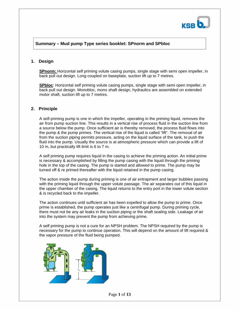
A self-priming pump is one in which the impeller, operating in the priming liquid, removes the air from pump suction line. This results in a vertical rise of process fluid in the suction line from a source below the pump. Once sufficient air is thereby removed, the process fluid flows into the pump & the pump primes. The vertical rise of the liquid is called “lift”. The removal of air from the suction piping permits pressure, acting on the liquid surface of the tank, to push the fluid into the pump. Usually the source is at atmospheric pressure which can provide a lift of 10 m, but practically lift limit is 6 to 7 m. A self priming pump requires liquid in the casing to achieve the priming action. An initial prime is necessary & accomplished by filling the pump casing with the liquid through the priming hole in the top of the casing. The pump is started and allowed to prime. The pump may be turned off & re primed thereafter with the liquid retained in the pump casing. The action inside the pump during priming is one of air entrapment and larger bubbles passing with the priming liquid through the upper volute passage. The air separates out of this liquid in the upper chamber of the casing. The liquid returns to the entry port in the lower volute section & is recycled back to the impeller. The action continues until sufficient air has been expelled to allow the pump to prime. Once prime is established, the pump operates just like a centrifugal pump. During priming cycle, there must not be any air leaks in the suction piping or the shaft sealing side. Leakage of air into the system may prevent the pump from achieving prime. A self priming pump is not a cure for an NPSH problem. The NPSH required by the pump is necessary for the pump to continue operation. This will depend on the amount of lift required & the vapor pressure of the fluid being pumped.
Summary – Mud pump Type series booklet: SPnorm and SPbloc
Page 2 of 13
3. Applications Suitable pump for pumping muddy water, sewage, polluted liquids including solids etc. applications where priming & foot valve is to be avoided. Industry wise applications: Industrial: pumping petroleum products, chemicals, effluents, Sewage, ash-water etc. Civil Construction: Dewatering foundation, trenches and pits. Mobile Machinery: Cooling water for marine engines & showels. Public utilities: Sewage pumping. Tiles & Marble industry: for handling waste water. Marine: Pumping water from docks, ports, vessels.
4. Driver Details TEFC, extended shaft motor for monobloc version. Voltage: 415 +/-10% for 3 phase AC & 280 +/- 10% for single phase AC. 0.75 kW / 1 HP available in single & 3 phase. IP44 protection as standard, IP55 on request. Temperature limited to class B insulation.
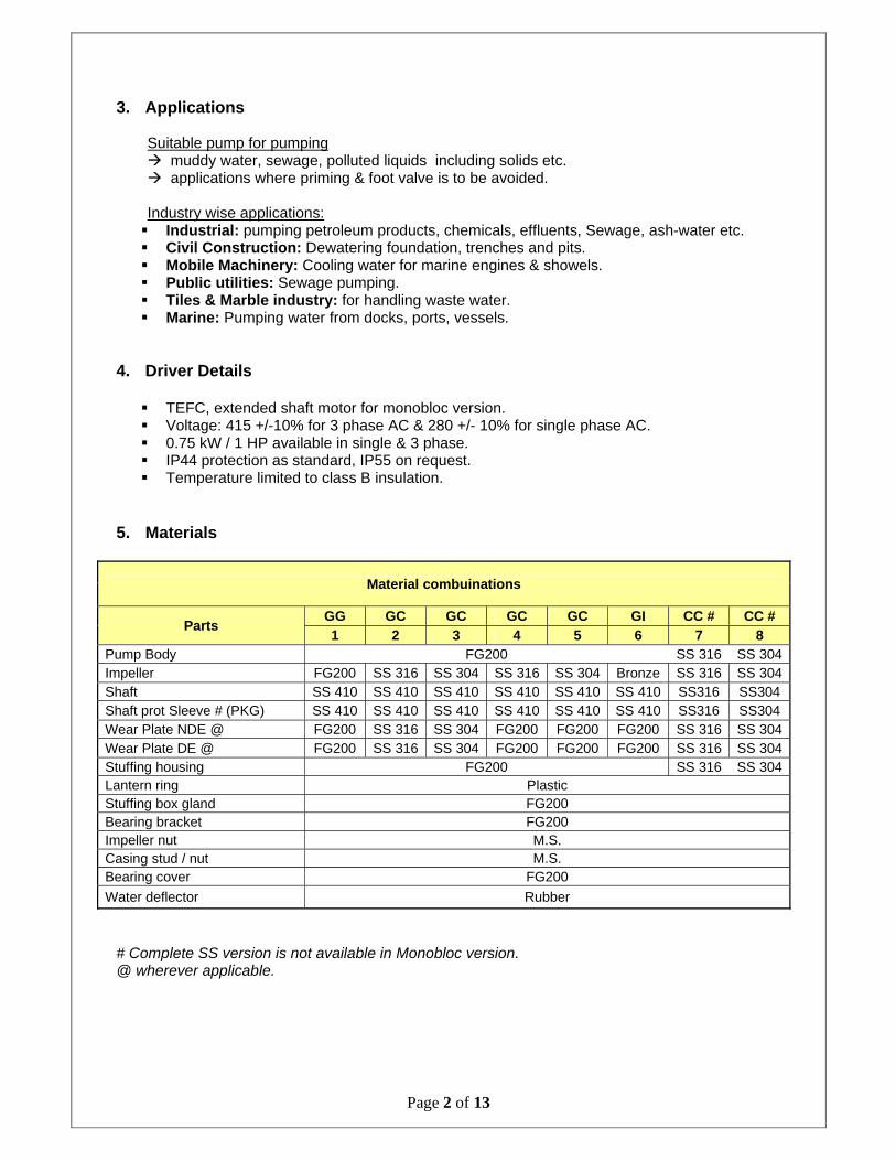
5. Materials
Material combuinations
Parts GG GC GC GC GC GI CC # CC # 1 2 3 4 5 6 7 8
Pump Body FG200 SS 316 SS 304Impeller FG200 SS 316 SS 304 SS 316 SS 304 Bronze SS 316 SS 304Shaft SS 410 SS 410 SS 410 SS 410 SS 410 SS 410 SS316 SS304 Shaft prot Sleeve # (PKG) SS 410 SS 410 SS 410 SS 410 SS 410 SS 410 SS316 SS304 Wear Plate NDE @ FG200 SS 316 SS 304 FG200 FG200 FG200 SS 316 SS 304Wear Plate DE @ FG200 SS 316 SS 304 FG200 FG200 FG200 SS 316 SS 304Stuffing housing FG200 SS 316 SS 304Lantern ring Plastic Stuffing box gland FG200 Bearing bracket FG200 Impeller nut M.S. Casing stud / nut M.S. Bearing cover FG200
Water deflector Rubber
# Complete SS version is not available in Monobloc version. @ wherever applicable.
Page 3 of 13
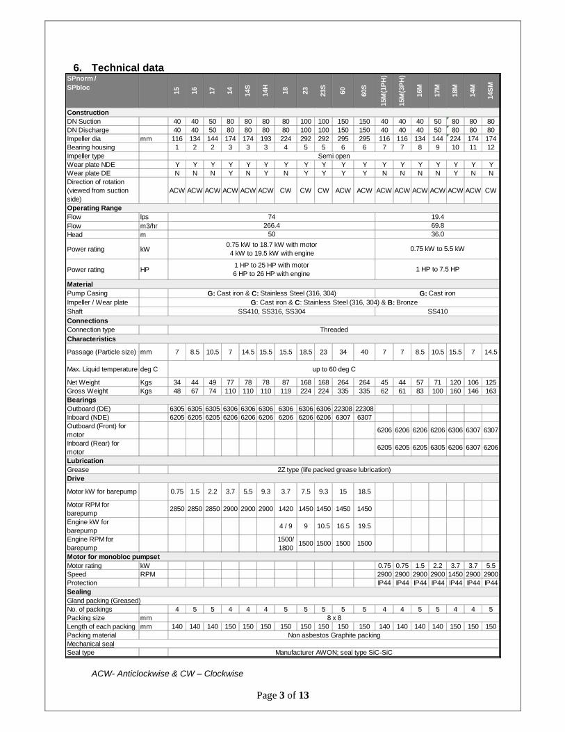
6. Technical data
ACW- Anticlockwise & CW – Clockwise
SPnorm /SPbloc
15 16 17 14 14S
14H
18 23 23S
60 60S
15M
(1P
H)
15M
(3P
H)
16M
17M
18M
14M
14S
M
ConstructionDN Suction 40 40 50 80 80 80 80 100 100 150 150 40 40 40 50 80 80 80DN Discharge 40 40 50 80 80 80 80 100 100 150 150 40 40 40 50 80 80 80Impeller dia mm 116 134 144 174 174 193 224 292 292 295 295 116 116 134 144 224 174 174Bearing housing 1 2 2 3 3 3 4 5 5 6 6 7 7 8 9 10 11 12Impeller type Semi openWear plate NDE Y Y Y Y Y Y Y Y Y Y Y Y Y Y Y Y Y YWear plate DE N N N Y N Y N Y Y Y Y N N N N Y N NDirection of rotation (viewed from suction side)
ACW ACW ACW ACW ACW ACW CW CW CW ACW ACW ACW ACW ACW ACW ACW ACW CW
Operating RangeFlow lpsFlow m3/hrHead m
Power rating kW
Power rating HP
MaterialPump CasingImpeller / Wear plateShaftConnectionsConnection typeCharacteristics
Passage (Particle size) mm 7 8.5 10.5 7 14.5 15.5 15.5 18.5 23 34 40 7 7 8.5 10.5 15.5 7 14.5
Max. Liquid temperature deg C
Net Weight Kgs 34 44 49 77 78 78 87 168 168 264 264 45 44 57 71 120 106 125Gross Weight Kgs 48 67 74 110 110 110 119 224 224 335 335 62 61 83 100 160 146 163BearingsOutboard (DE) 6305 6305 6305 6306 6306 6306 6306 6306 6306 22308 22308Inboard (NDE) 6205 6205 6205 6206 6206 6206 6206 6206 6206 6307 6307Outboard (Front) for motor
6206 6206 6206 6206 6306 6307 6307
Inboard (Rear) for motor
6205 6205 6205 6305 6206 6307 6206
LubricationGrease 2Z type (life packed grease lubrication)Drive
Motor kW for barepump 0.75 1.5 2.2 3.7 5.5 9.3 3.7 7.5 9.3 15 18.5
Motor RPM for barepump
2850 2850 2850 2900 2900 2900 1420 1450 1450 1450 1450
Engine kW for barepump
4 / 9 9 10.5 16.5 19.5
Engine RPM for barepump
1500/1800
1500 1500 1500 1500
Motor for monobloc pumpsetMotor rating kW 0.75 0.75 1.5 2.2 3.7 3.7 5.5Speed RPM 2900 2900 2900 2900 1450 2900 2900Protection IP44 IP44 IP44 IP44 IP44 IP44 IP44SealingGland packing (Greased)No. of packings 4 5 5 4 4 4 5 5 5 5 5 4 4 5 5 4 4 5Packing size mm 8 x 8Length of each packing mm 140 140 140 150 150 150 150 150 150 150 150 140 140 140 140 150 150 150Packing material Non asbestos Graphite packingMechanical sealSeal type Manufacturer AWON; seal type SiC-SiC
0.75 kW to 18.7 kW with motor4 kW to 19.5 kW with engine
0.75 kW to 5.5 kW
1 HP to 25 HP with motor6 HP to 26 HP with engine
1 HP to 7.5 HP
74266.4
50
19.469.836.0
up to 60 deg C
G: Cast iron & C: Stainless Steel (316, 304) G: Cast ironG: Cast iron & C: Stainless Steel (316, 304) & B: Bronze
SS410, SS316, SS304 SS410
Threaded

Page 4 of 13
7. Performance table (Flow in LPS) (Note: Performance applicable to liquid of specific gravity 1 & viscosity as of water)
Page 5 of 13
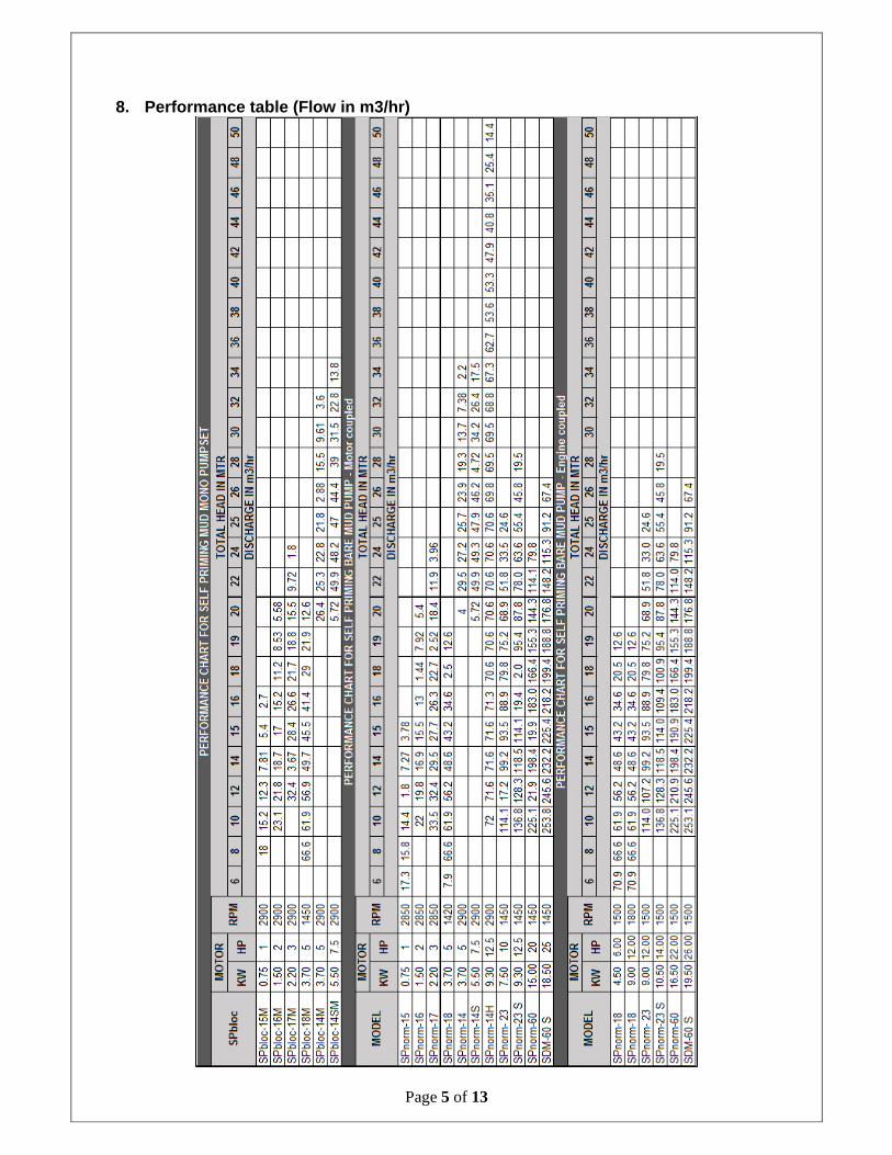
8. Performance table (Flow in m3/hr)
Page 6 of 13
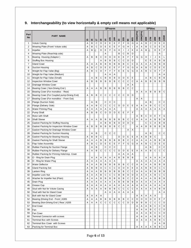
9. Interchangeability (to view horizontally & empty cell means not applicable)
Part No
PART NAME
15 16 17 18 14 14S
14H
23 23S
60 60S
15M
(1P
H)
15M
(3P
H)
16M
17M
18M
14M
14S
M
1 Volute Casing A B C D E E E F F G G A A B C D E E
2 Wearing Plate (Front/ Volute side) A B C D E E E F G H I A A B C D E E
3 Impeller A B C D E F G H I J K A A B C D E F
4 Wearing Plate (Rear/Adp.side) A B C B D A
5 Bearing Housing (Adaptor ) A B B C D D D E E F F G G H I J K L
6 Stuffing Box Housing A B B B C C D D E E A B B
7 Gland Cover A A A B B B B B B C C A A A A B B B
8 Suction Housing A B C D E E E F F G G A A B C D E E
9 Weight for Flap Valve (Big) A B C D F F F E E G G A A B C D F F
10 Weight for Flap Valve (Medium) A A A A A
11 Weight for Flap Valve (Small) A B C B B B D D E E A B C B B
12 Inspection Window Cover A B B B B B B C C C C A A B B B B B
13 Drainage Window Cover A A
14 Bearing Cover ( Non-Driving End ) A A A B B B B B B C C
15 Bearing Cover (For monobloc - Rear) A A A B B B C
16 Bearing Cover (For Coupled pump-Driving End) A B B C C C C C C D D
17 Bearing Cover (For monobloc - Front Out) A A
19 Flange (Suction Side) A B C C C A B C C
20 Flange (Delivery Side) A A B C C C C D D E E A A A B C C C
21 Water Priming Plug A A A A A A A A A A A A A A
22 Pump Shaft A B B C D D D E E F F
23 Rotor with Shaft A B C D E F G
24 Shaft Sleeve A A A B B B B B B C C A A A A B B B
25 Gasket Packing for Stuffing Housing A B B B D D D D C C A B B
26 Gasket Packing for Inspection Window Cover A B B B B B B C C A A B B B B B
27 Gasket Packing for Drainage Window Cover A A
28 Gasket Packing for Suction Housing A B C C C A B C C
29 Gasket Packing for Bearing Housing A B B C D D E E A A B B C
30 Gasket Packing for Shaft Sleeve A A A B B B B B B C C A A A A B B B
31 Flap Valve Assembly A B C D E E E F F G G A A B C D E E
32 Rubber Packing for Suction Flange A B C C C A B C C
33 Rubber Packing for Delivery Flange A A B C C C C D D E E A A A B C C C
34 Rubber Packing for Priming Hole/insp. Cover A A A A
35 O - Ring for Drain Plug A A A A A A B B B B A A A A A
36 O - Ring for Water Plug A A A A A A A A A A A A A A
37 Water Deflector A A A B B B B B B C C A A A A B B B
38 Gland Packing Set A B B D C C C D D E E A A B B D C C
39 Lantern Ring A A A B B B B B B C C A A A B B B B
42 Impeller Lock Nut A A A B C C C B B D D A A A A B C C
43 Washer for Impeller Nut (Plain) A A A B B B B B B C C A A A A B B B
45 Drain Plug A A A A A A A B B B B A A A A A A A
46 Grease Cup A A A A A A A A A A A A A A A A A A
49 Stud with Nut for Volute Casing A A A A B B B C C C C A A A A A B B
50 Stud with Nut for Gland Cover A A A A A A A A A
51 Bolt with Nut for Gland Cover A A A A A A A A A
52 Bearing (Driving End - Front ) 6305 A A A B B B B B B C C D D D D E E F
53 Bearing (Non-Driving End ( Rear ) 6205 A A A C C C C C C D D B B B C C C D
57 End Cover A A A B C C D
58 Fan A A A B C C D
59 Fan Cover A A A B C C D
60 Terminal Connector with screws A A A A B B C
61 Terminal Box with Screws A A A A B B C
62 Terminal Box Cover with Screws A A B
63 Packing for Terminal Box A A A A B B C
SPnorm SPbloc
Page 7 of 13
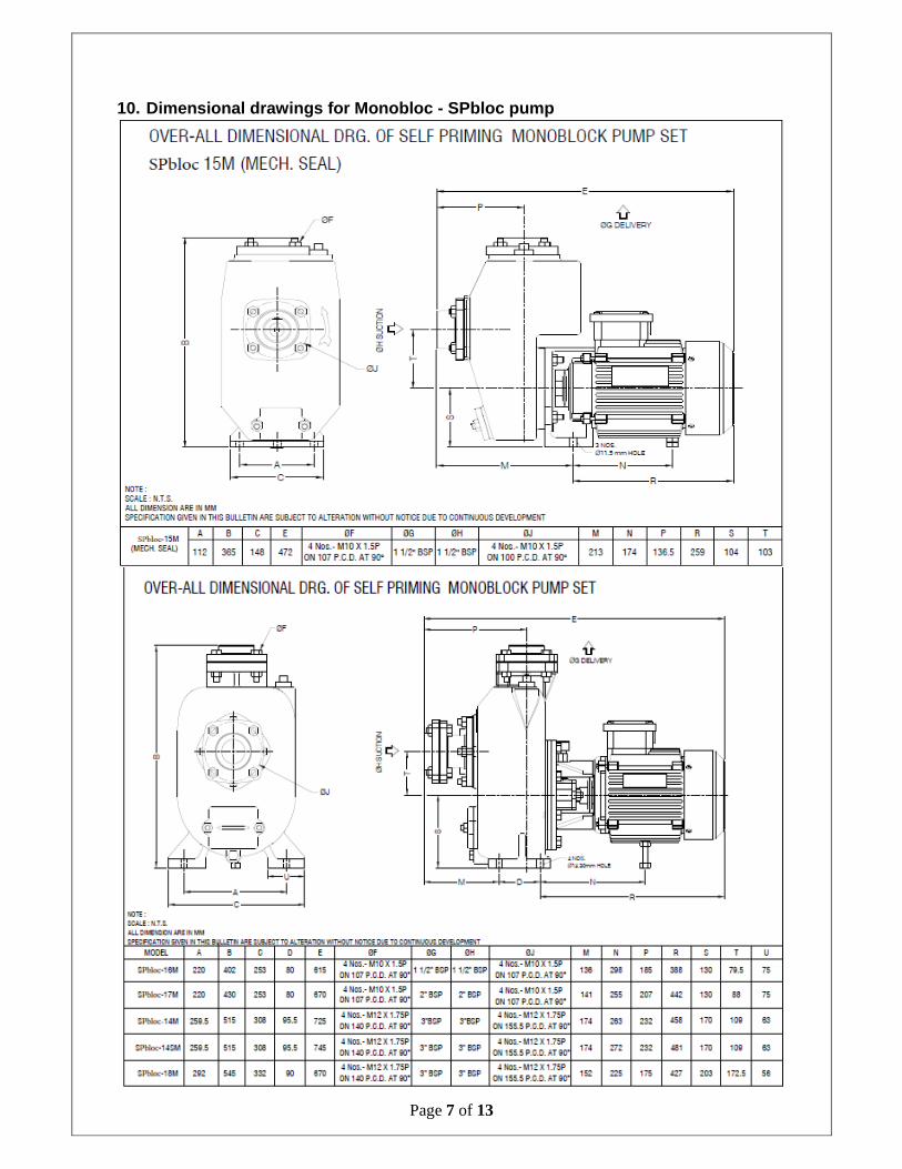
10. Dimensional drawings for Monobloc - SPbloc pump
Page 8 of 13
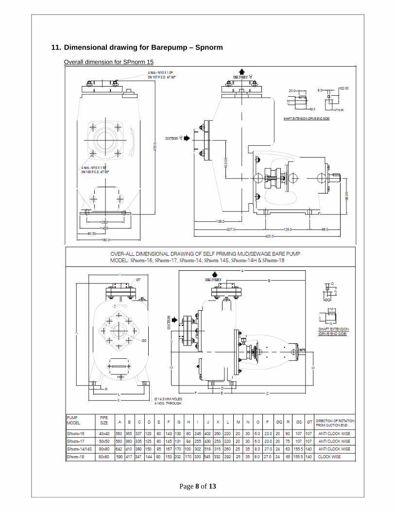
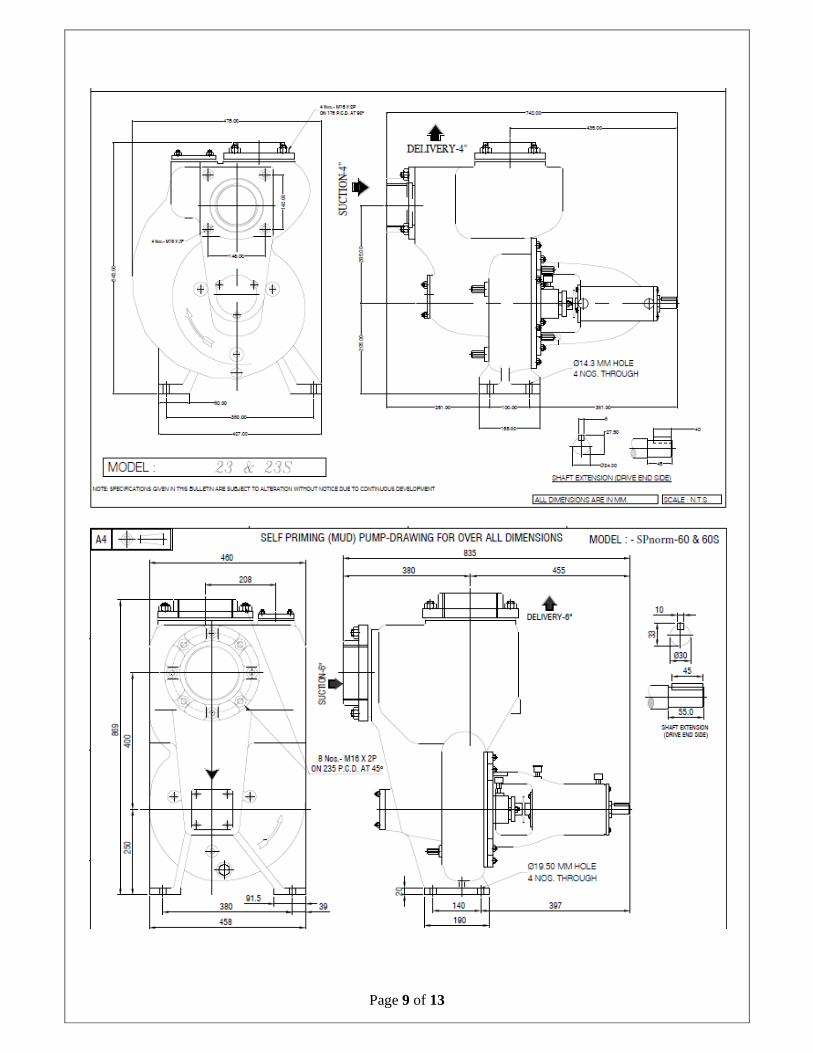
11. Dimensional drawing for Barepump – Spnorm Overall dimension for SPnorm 15
Page 9 of 13

Page 10 of 13
12. Exploded views & Cross sectional Model
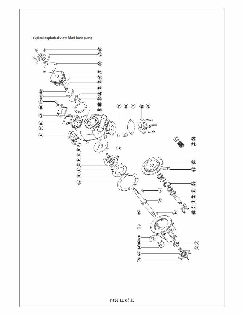
Page 11 of 13
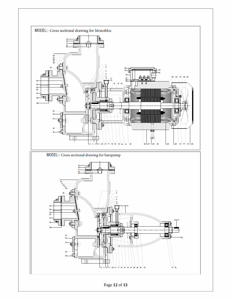
Page 12 of 13
Page 13 of 13
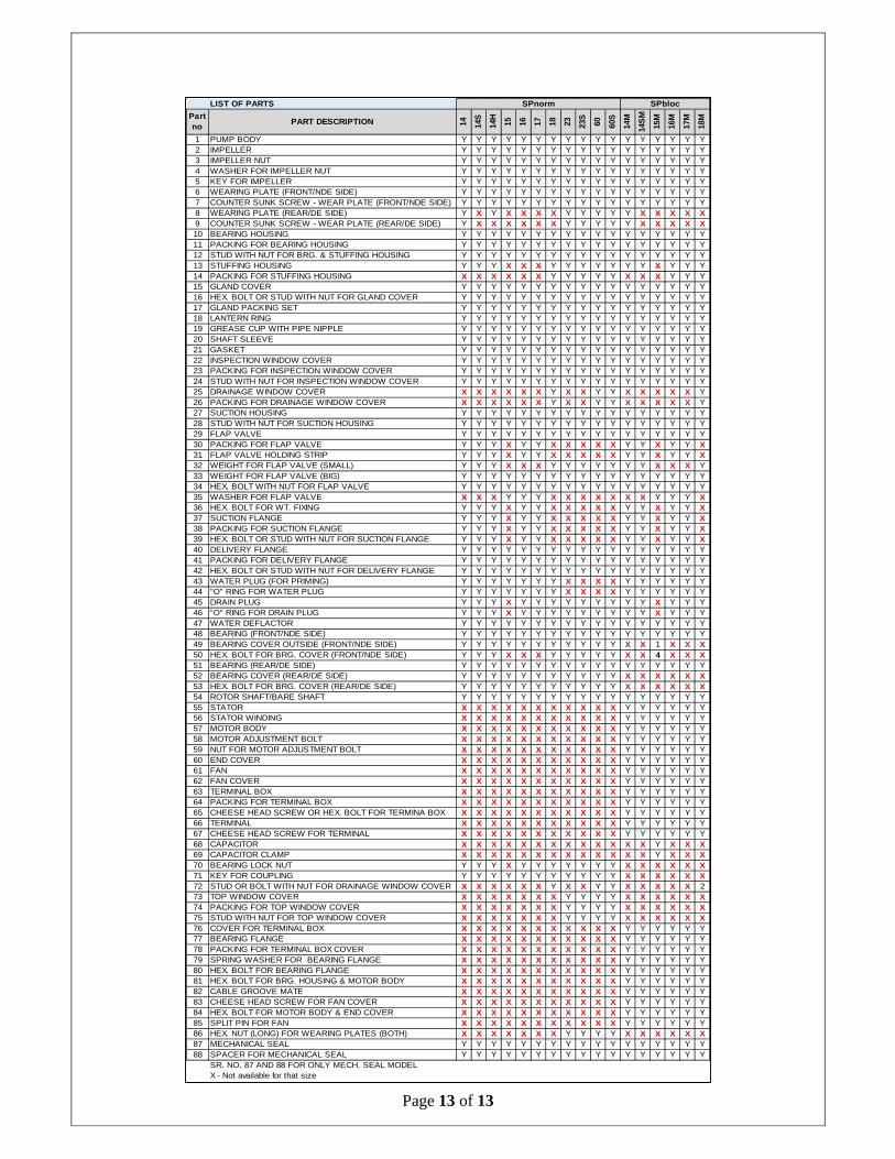
LIST OF PARTS
Part no
PART DESCRIPTION 14 14S
14H
15 16 17 18 23 23S
60 60S
14M
14S
M
15M
16M
17M
18M
1 PUMP BODY Y Y Y Y Y Y Y Y Y Y Y Y Y Y Y Y Y2 IMPELLER Y Y Y Y Y Y Y Y Y Y Y Y Y Y Y Y Y3 IMPELLER NUT Y Y Y Y Y Y Y Y Y Y Y Y Y Y Y Y Y4 WASHER FOR IMPELLER NUT Y Y Y Y Y Y Y Y Y Y Y Y Y Y Y Y Y5 KEY FOR IMPELLER Y Y Y Y Y Y Y Y Y Y Y Y Y Y Y Y Y6 WEARING PLATE (FRONT/NDE SIDE) Y Y Y Y Y Y Y Y Y Y Y Y Y Y Y Y Y7 COUNTER SUNK SCREW - WEAR PLATE (FRONT/NDE SIDE) Y Y Y Y Y Y Y Y Y Y Y Y Y Y Y Y Y8 WEARING PLATE (REAR/DE SIDE) Y X Y X X X X Y Y Y Y Y X X X X X9 COUNTER SUNK SCREW - WEAR PLATE (REAR/DE SIDE) Y X X X X X X Y Y Y Y Y X X X X X10 BEARING HOUSING Y Y Y Y Y Y Y Y Y Y Y Y Y Y Y Y Y11 PACKING FOR BEARING HOUSING Y Y Y Y Y Y Y Y Y Y Y Y Y Y Y Y Y12 STUD WITH NUT FOR BRG. & STUFFING HOUSING Y Y Y Y Y Y Y Y Y Y Y Y Y Y Y Y Y13 STUFFING HOUSING Y Y Y X X X Y Y Y Y Y Y Y X Y Y Y14 PACKING FOR STUFFING HOUSING X X X X X X Y Y Y Y Y X X X Y Y Y15 GLAND COVER Y Y Y Y Y Y Y Y Y Y Y Y Y Y Y Y Y16 HEX. BOLT OR STUD WITH NUT FOR GLAND COVER Y Y Y Y Y Y Y Y Y Y Y Y Y Y Y Y Y17 GLAND PACKING SET Y Y Y Y Y Y Y Y Y Y Y Y Y Y Y Y Y18 LANTERN RING Y Y Y Y Y Y Y Y Y Y Y Y Y Y Y Y Y19 GREASE CUP WITH PIPE NIPPLE Y Y Y Y Y Y Y Y Y Y Y Y Y Y Y Y Y20 SHAFT SLEEVE Y Y Y Y Y Y Y Y Y Y Y Y Y Y Y Y Y21 GASKET Y Y Y Y Y Y Y Y Y Y Y Y Y Y Y Y Y22 INSPECTION WINDOW COVER Y Y Y Y Y Y Y Y Y Y Y Y Y Y Y Y Y23 PACKING FOR INSPECTION WINDOW COVER Y Y Y Y Y Y Y Y Y Y Y Y Y Y Y Y Y24 STUD WITH NUT FOR INSPECTION WINDOW COVER Y Y Y Y Y Y Y Y Y Y Y Y Y Y Y Y Y25 DRAINAGE WINDOW COVER X X X X X X Y X X Y Y X X X X X Y26 PACKING FOR DRAINAGE WINDOW COVER X X X X X X Y X X Y Y X X X X X Y27 SUCTION HOUSING Y Y Y Y Y Y Y Y Y Y Y Y Y Y Y Y Y28 STUD WITH NUT FOR SUCTION HOUSING Y Y Y Y Y Y Y Y Y Y Y Y Y Y Y Y Y29 FLAP VALVE Y Y Y Y Y Y Y Y Y Y Y Y Y Y Y Y Y30 PACKING FOR FLAP VALVE Y Y Y X Y Y X X X X X Y Y X Y Y X31 FLAP VALVE HOLDING STRIP Y Y Y X Y Y X X X X X Y Y X Y Y X32 WEIGHT FOR FLAP VALVE (SMALL) Y Y Y X X X Y Y Y Y Y Y Y X X X Y33 WEIGHT FOR FLAP VALVE (BIG) Y Y Y Y Y Y Y Y Y Y Y Y Y Y Y Y Y34 HEX. BOLT WITH NUT FOR FLAP VALVE Y Y Y Y Y Y Y Y Y Y Y Y Y Y Y Y Y35 WASHER FOR FLAP VALVE X X X Y Y Y X X X X X X X Y Y Y X36 HEX. BOLT FOR WT. FIXING Y Y Y X Y Y X X X X X Y Y X Y Y X37 SUCTION FLANGE Y Y Y X Y Y X X X X X Y Y X Y Y X38 PACKING FOR SUCTION FLANGE Y Y Y X Y Y X X X X X Y Y X Y Y X39 HEX. BOLT OR STUD WITH NUT FOR SUCTION FLANGE Y Y Y X Y Y X X X X X Y Y X Y Y X40 DELIVERY FLANGE Y Y Y Y Y Y Y Y Y Y Y Y Y Y Y Y Y41 PACKING FOR DELIVERY FLANGE Y Y Y Y Y Y Y Y Y Y Y Y Y Y Y Y Y42 HEX. BOLT OR STUD WITH NUT FOR DELIVERY FLANGE Y Y Y Y Y Y Y Y Y Y Y Y Y Y Y Y Y43 WATER PLUG (FOR PRIMING) Y Y Y Y Y Y Y X X X X Y Y Y Y Y Y44 "O" RING FOR WATER PLUG Y Y Y Y Y Y Y X X X X Y Y Y Y Y Y45 DRAIN PLUG Y Y Y X Y Y Y Y Y Y Y Y Y X Y Y Y46 "O" RING FOR DRAIN PLUG Y Y Y X Y Y Y Y Y Y Y Y Y X Y Y Y47 WATER DEFLACTOR Y Y Y Y Y Y Y Y Y Y Y Y Y Y Y Y Y48 BEARING (FRONT/NDE SIDE) Y Y Y Y Y Y Y Y Y Y Y Y Y Y Y Y Y49 BEARING COVER OUTSIDE (FRONT/NDE SIDE) Y Y Y Y Y Y Y Y Y Y Y X X 1 X X X50 HEX. BOLT FOR BRG. COVER (FRONT/NDE SIDE) Y Y Y X X X Y Y Y Y Y X X 4 X X X51 BEARING (REAR/DE SIDE) Y Y Y Y Y Y Y Y Y Y Y Y Y Y Y Y Y52 BEARING COVER (REAR/DE SIDE) Y Y Y Y Y Y Y Y Y Y Y X X X X X X53 HEX. BOLT FOR BRG. COVER (REAR/DE SIDE) Y Y Y Y Y Y Y Y Y Y Y X X X X X X54 ROTOR SHAFT/BARE SHAFT Y Y Y Y Y Y Y Y Y Y Y Y Y Y Y Y Y55 STATOR X X X X X X X X X X X Y Y Y Y Y Y56 STATOR WINDING X X X X X X X X X X X Y Y Y Y Y Y57 MOTOR BODY X X X X X X X X X X X Y Y Y Y Y Y58 MOTOR ADJUSTMENT BOLT X X X X X X X X X X X Y Y Y Y Y Y59 NUT FOR MOTOR ADJUSTMENT BOLT X X X X X X X X X X X Y Y Y Y Y Y60 END COVER X X X X X X X X X X X Y Y Y Y Y Y61 FAN X X X X X X X X X X X Y Y Y Y Y Y62 FAN COVER X X X X X X X X X X X Y Y Y Y Y Y63 TERMINAL BOX X X X X X X X X X X X Y Y Y Y Y Y64 PACKING FOR TERMINAL BOX X X X X X X X X X X X Y Y Y Y Y Y65 CHEESE HEAD SCREW OR HEX. BOLT FOR TERMINA BOX X X X X X X X X X X X Y Y Y Y Y Y66 TERMINAL X X X X X X X X X X X Y Y Y Y Y Y67 CHEESE HEAD SCREW FOR TERMINAL X X X X X X X X X X X Y Y Y Y Y Y68 CAPACITOR X X X X X X X X X X X X X Y X X X69 CAPACITOR CLAMP X X X X X X X X X X X X X Y X X X70 BEARING LOCK NUT Y Y Y X Y Y Y Y Y Y Y X X X X X X71 KEY FOR COUPLING Y Y Y Y Y Y Y Y Y Y Y X X X X X X72 STUD OR BOLT WITH NUT FOR DRAINAGE WINDOW COVER X X X X X X Y X X Y Y X X X X X 273 TOP WINDOW COVER X X X X X X X Y Y Y Y X X X X X X74 PACKING FOR TOP WINDOW COVER X X X X X X X Y Y Y Y X X X X X X75 STUD WITH NUT FOR TOP WINDOW COVER X X X X X X X Y Y Y Y X X X X X X76 COVER FOR TERMINAL BOX X X X X X X X X X X X Y Y Y Y Y Y77 BEARING FLANGE X X X X X X X X X X X Y Y Y Y Y Y78 PACKING FOR TERMINAL BOX COVER X X X X X X X X X X X Y Y Y Y Y Y79 SPRING WASHER FOR BEARING FLANGE X X X X X X X X X X X Y Y Y Y Y Y80 HEX. BOLT FOR BEARING FLANGE X X X X X X X X X X X Y Y Y Y Y Y81 HEX. BOLT FOR BRG. HOUSING & MOTOR BODY X X X X X X X X X X X Y Y Y Y Y Y82 CABLE GROOVE MATE X X X X X X X X X X X Y Y Y Y Y Y83 CHEESE HEAD SCREW FOR FAN COVER X X X X X X X X X X X Y Y Y Y Y Y84 HEX. BOLT FOR MOTOR BODY & END COVER X X X X X X X X X X X Y Y Y Y Y Y85 SPLIT PIN FOR FAN X X X X X X X X X X X Y Y Y Y Y Y86 HEX. NUT (LONG) FOR WEARING PLATES (BOTH) X X X X X X X Y Y Y Y X X X X X X87 MECHANICAL SEAL Y Y Y Y Y Y Y Y Y Y Y Y Y Y Y Y Y88 SPACER FOR MECHANICAL SEAL Y Y Y Y Y Y Y Y Y Y Y Y Y Y Y Y Y
SR. NO. 87 AND 88 FOR ONLY MECH. SEAL MODELX - Not available for that size
SPnorm SPbloc