sulfur management in natural gas treating plants: a state ... · sulfur management in natural gas...
TRANSCRIPT

Sulfur Management in Natural Gas Treating Plants: A state-of-the-art approach for LNG Plants
Peter Hawes, ZEOCHEM AG, Uetikon/ Switzerland Justin Hearn, BASF AG, Ludwigshafen/ Germany Max-Michael Weiss, Lurgi Oel •
Gas • Chemie GmbH, Frankfurt/ Germany Presented by:
Dr. Ulrich Wagner, Executive Director Technology, Lurgi Oel Gas Chemie GmbH
12th International Oil, Gas and Petrochemical Congress, Iran
ABSTRACT
Natural gas demand for the production of pipeline gas, liquefied natural gas (LNG) or as feedstock for the production of chemicals, such as methanol or fertilizers is growing worldwide. A growth rate above 8% per year is predicted for some regions.
Proven natural gas reserves are growing, too. But very often the quality of the raw
gas worsens because it features high concentrations of sulfur components like H2S
and mercaptans for example, and/or CO2. This makes the upgrading of the gas for
final use complex and frequently imposes a heavy burden on the environment.
In LNG Plants, acidic components like H 2O and CO2 are removed by means of
chemically absorbing Acid Gas Removal units (AGR), whereas the Mercaptans are removed in Molecular Sieve Units (MSU). The enriched acid gas from the AGR is processed to elemental sulfur in a Sulfur Recovery Unit (SRU), consisting of a Claus unit and an associated tailgas treating unit if higher recovery rates are specified for the SRU itself. The MSU as a batch process, is periodically regenerated thermally. The mercaptan-rich regeneration gas is often merely incinerated in a boiler. This leads to an environmental burden, because only 93 to 96 % of the sulfur contained in the raw natural gas are recovered as elemental sulfur. To eliminate these constraints, Lurgi has developed a new concept for improving the overall sulfur recovery rate and curbing capital investment and operating costs. This new concept is based on Lurgi's proprietary know-how and encompasses the following key processes:
• AGR with aMDEA® of BASF
• SRU with Lurgi Claus®, LTGT®, AQUISULF® • MSU with 13X Zeolite of ZEOCHEM
• RSH Recovery with PURISOL®
Page 1 of 18Gas To Chemicals
2/24/2004mk:@MSITStore:E:\congress.chm::/UWB1000.htm

This concept allows for an overall sulfur recovery rate of up to 99 % +.
Lurgi has recently licensed this 'Lurgi Sulfur Management Concept' technology to an Iranian customer. Details of the plant will be presented and benefits will be discussed in this paper.
Introduction
Natural gas is one of the major energy sources on earth. In the early days of exploitation of fossil energy sources it was often simply flared, as it was just an unwanted by-product of oil production. In recent decades, the situation has changed tremendously and natural gas has become more and more important. World's population is growing and naturally the demand for more energy and food is growing. Further, many countries are trying to improve their living standards by growing their basic industries.
That is why the natural gas demand for the production of pipeline gas, liquefied natural gas (LNG) or, as feedstock for the production of chemicals such as methanol or fertilizers is growing worldwide.
A growth rate above 8% per year is predicted for some regions.
New natural gas sources
Proven natural gas reserves are growing, too. But very often the quality of the raw
gas worsens because it features high concentrations of sulfur components like H2S, COS and Mercaptans for example, and/or CO2. This makes the upgrading of the
gas for final use very complex and frequently imposes a heavy burden on the environment.
Page 2 of 18Gas To Chemicals
2/24/2004mk:@MSITStore:E:\congress.chm::/UWB1000.htm

There have been new reservoirs explored, mainly of associated gas.
Some prominent fields are:
Caspian Sea (Tengiz and Kashagan), very sour gas with up to 25 % H2S and up to 25 % of CO2.
Persian Gulf (North Field and South Pars), sour gas with major portions of Mercaptans and COS.
Southeast Asia (Natuna and others), sour gas with up 70 % CO2.
A lot of efforts have been made to utilize the so-called stranded gas, i.e. associated gas actually being flared in desert areas. Having neither infrastructure nor a local market, this only makes sense by the production of high value added and transportable products. This in turn calls for specialized gas treatment.
Set-up of a typical natural gas treating plant
Natural gas coming from the well typically contains hydrocarbons, nitrogen, CO2,
H2S together with many other impurities. A treatment of the gas is required in
order to make it suited for the various applications. Thereby, special attention is
paid on the sour compounds CO2 and H2S. When the gas is used as sales gas, CO2
might be left in the treated gas up to several percent. Higher concentrations can lead to corrosion problems in downstream, equipment and pipelines, thus making a partial removal of CO2 necessary. For an application where the treated gas is undergoing cryogenic treatment, like NGL recovery or LNG production, the specification is 50 ppm by volume, i.e. virtually all of the CO2 needs to be removed.
Page 3 of 18Gas To Chemicals
2/24/2004mk:@MSITStore:E:\congress.chm::/UWB1000.htm

The sulfur compounds have to be removed in any case in order to avoid corrosion, for environmental reasons, but also to meet specifications for the final products like NGL or LNG.
In LNG Plants, acidic components like H 2S and CO2 are removed by means of
chemically absorbing Acid Gas Removal units (AGR), whereas the moisture and the mercaptans are removed in Molecular Sieve Units (MSU). The enriched acid gas from the AGR is processed to elemental sulfur in a Sulfur Recovery Unit (SRU), consisting of a Claus unit and an associated tailgas treating unit if higher recovery rates are specified for the SRU itself.
The MSU as a batch process is periodically regenerated thermally. The mercaptan-rich regeneration gas is often merely incinerated in a boiler or flared. By that a measurable part of the possible hydrocarbon product is lost. This leads further to an environmental burden, because only 93 to 96 % of the sulfur contained in the raw natural gas are recovered as elemental sulfur.
If the mercaptans of the regeneration gas could be recovered as elemental sulfur, this would result in a drastic reduction of the environmental pollution. Up to 99.3% sulfur recovered would be possible.
There are other concepts available on the market with sulfur removal done in the liquid products downstream. For example, dehydration of the sweetened gas is done by means of a glycol-absorbing unit or a mole-sieve unit, letting pass all the mercaptans. These have to be removed from the recovered natural gas liquids individually by means of a catalytic caustic treatment, which leads finally to an undesired waste product (Di-Sulfide-Oil). Now in more modern plants molecular sieves are used for this task. Here the regeneration procedure of the MSU in liquid service is similar to those in gas-phase service, still leaving the question where to get rid of the RSH-containing regeneration gases. In-depth studies have shown economic benefits for the gas-phase RSH removal.
Page 4 of 18Gas To Chemicals
2/24/2004mk:@MSITStore:E:\congress.chm::/UWB1000.htm

Development of the Sulphur Management Concept
» Puzzle of processes
For a new natural gas treating plant to be built a series of tasks are to be performed:
• Pre-Feasibility study
• Feasibility study
• FEED contract
• EPC contract
A potential investor will hire a consultant or has his own in-house staff to perform the first two tasks. Here the available technologies are screened, judged and finally selected to be part of the front-end engineering design. The FEED contractor harmonizes the numerous interfaces in the puzzle of process pieces and prepares the basis of the EPC stage. Any piece selected in the early stages, which then turns out during FEED not fitting in the overall scheme or even fails at a later stage is a very costly item.
Thus it is of key importance to make the right choice during licensor selection.
» Responsibilities and Liabilities
Taking the typical example of the natural gas treating set-up, there are four main blocks, which usually means four licensors:
• Acid Gas Removal • Molecular Sieve Unit • Mercury Removal • Sulphur Recovery Unit
Four license contracts to be made, each defining thoroughly the battery limit conditions of the single unit. Four different sets of guarantees and liabilities as well as lot of interfaces between the licensed blocks. This often results in four good excuses, when it doesn't work accordingly when the plant is in operation. If one unit fails to deliver the negotiated feed to the next unit it is nearly impossible to claim for liabilities of the other three licensors. Each licensor will include his own safety margins within his design for safeguarding his liabilities. Thus the overall concept is not optimized regarding capital and operating expenditures.
» OmniSulf®, the state-of-the-art-approach
To eliminate all these constraints discussed above, a new concept has been developed for improving, but not limited to, the overall sulfur recovery rate and curbing capital investment and operating costs.
The trade name is OmniSulf® (former Lurgi Sulfur Management Complex –LSMC).
Page 5 of 18Gas To Chemicals
2/24/2004mk:@MSITStore:E:\congress.chm::/UWB1000.htm
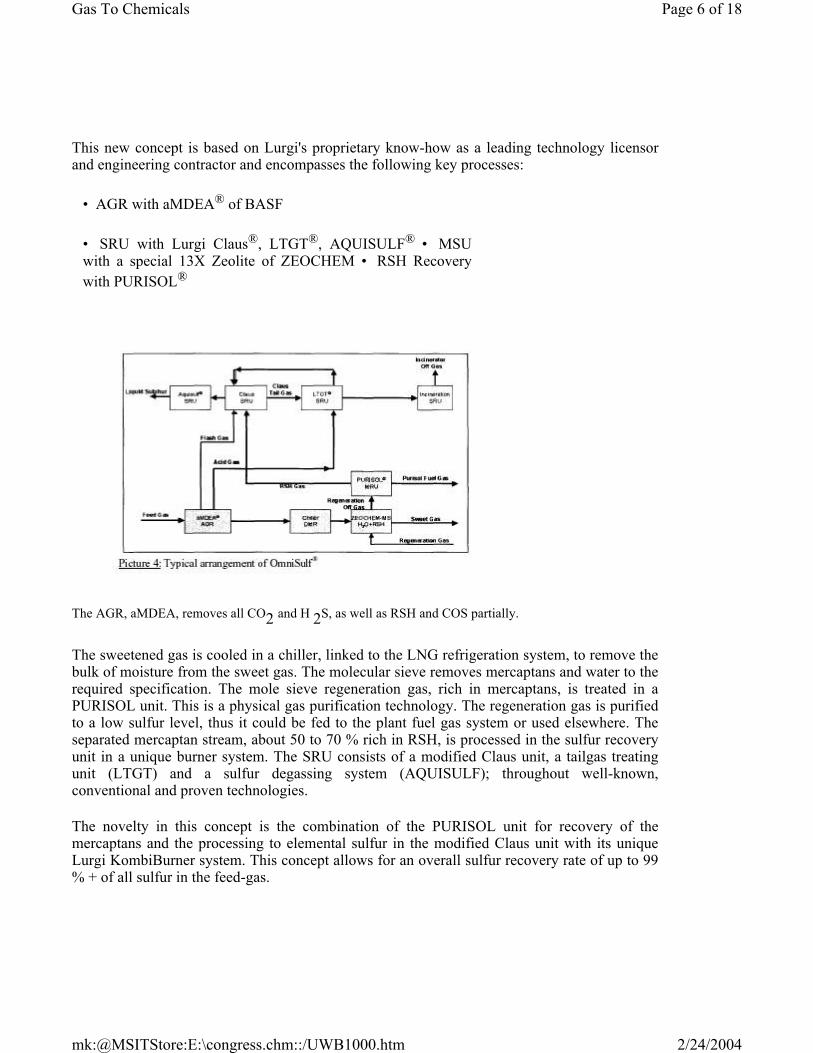
This new concept is based on Lurgi's proprietary know-how as a leading technology licensor and engineering contractor and encompasses the following key processes:
• AGR with aMDEA® of BASF
• SRU with Lurgi Claus®, LTGT®, AQUISULF® • MSU with a special 13X Zeolite of ZEOCHEM • RSH Recovery with PURISOL®
The AGR, aMDEA, removes all CO2 and H 2S, as well as RSH and COS partially.
The sweetened gas is cooled in a chiller, linked to the LNG refrigeration system, to remove the bulk of moisture from the sweet gas. The molecular sieve removes mercaptans and water to the required specification. The mole sieve regeneration gas, rich in mercaptans, is treated in a PURISOL unit. This is a physical gas purification technology. The regeneration gas is purified to a low sulfur level, thus it could be fed to the plant fuel gas system or used elsewhere. The separated mercaptan stream, about 50 to 70 % rich in RSH, is processed in the sulfur recovery unit in a unique burner system. The SRU consists of a modified Claus unit, a tailgas treating unit (LTGT) and a sulfur degassing system (AQUISULF); throughout well-known, conventional and proven technologies.
The novelty in this concept is the combination of the PURISOL unit for recovery of the mercaptans and the processing to elemental sulfur in the modified Claus unit with its unique Lurgi KombiBurner system. This concept allows for an overall sulfur recovery rate of up to 99 % + of all sulfur in the feed-gas.
Page 6 of 18Gas To Chemicals
2/24/2004mk:@MSITStore:E:\congress.chm::/UWB1000.htm

With this concept the following is achieved:
Single line responsibility:
? One license contract, one overall guarantee and liability, one transparent license fee
? The overall design is done by a single company, Lurgi
? Tailor-made design to avoid multiplying internal design margins; which can result in significant CAPEX and OPEX savings
Full flexibility:
? The three (non-American) partners, Lurgi, BASF, ZEOCHEM, are among the leaders in their respective fields. ? Thus OmniSulf® can be licensed without restrictions, to practically all parts of the sales gas and LNG-producing world. ? It can be tailored as the full concept for the production of sulfur or, e.g. restricted to fuelgas treatment and acid gas re-injection, only. See picture 5, below.
Besides the NIOC LNG project, where this sulfur management solution was already licensed, there are a number of sales gas and LNG projects having already selected or are considering this attractive technology option.
Status of the NIOC LNG project
In 2001 Lurgi has licensed this 'Lurgi Sulfur Management Complex' technology for the first Iranian LNG project to NIOC International, Tehran. The basic engineering of the LSMC has been completed and JGC, as the contractor, is integrating this package in the overall FEED.
Page 7 of 18Gas To Chemicals
2/24/2004mk:@MSITStore:E:\congress.chm::/UWB1000.htm

The FEED is expected to be finished end of this year. Parallel basic engineering have been made by competing licensors of the LNG cryogenic section. The selection of the LNG technology is expected soon.
The plant will be located at the South Pars Gas Field in Iran.
Two trains of 780 MMSCFD each will operate at a feed gas pressure of 68 bar.
A total of 2 x 367 t/d of sulfur, degassed to below 10 mg H 2S/kg S, will be
produced.
As easily could be deducted from the balance between feed gas and sweet product
gas, the losses are essentially limited to the CO2 and the H2S removed. Any
hydrocarbon losses are minimized.
Process guarantees given for the NIOC LNG project:
• Overall Sulfur recovery rate = 99 % • Purisol Fuel gas purity = 100 ppm v RSH • Off gas to
atmosphere = 10 ppm wt H2S • Sweet gas to LNG plant: CO2
= 50 ppm H2O = 1 ppm H2S = 3.5 ppm RSH = 5 ppm Total S = 17.5 ppm
Page 8 of 18Gas To Chemicals
2/24/2004mk:@MSITStore:E:\congress.chm::/UWB1000.htm

Picture 7: Overall guarantees given for the NIOC LNG project
Guarantees given on the sweet gas quality could be more stringent if a customer needs this.
aMDEA® in LNG service
The activated MDEA technology has been developed for more than 30 years now and is licensed by BASF AG and authorized sub-licensors. It uses an aqueous mixture of generic MDEA (Methyl-Di-Ethanol-Amine) and a proprietary activator. Its outstanding performance has been proven in more than 100 operating plants. With regard to its characteristics like a very low hydrocarbon co-absorption rate, the energy-efficient solvent regeneration and, last but not least, being non-degrading/non-corrosive, activated MDEA acts as a benchmark for competing technologies. This triggered an ongoing development of similar solvents or mere copies.
• Corrosion
An illustrative example of the non-corrosive behavior of the aMDEA solvent is the solution swap performed at P.T. Badak in Indonesia. P.T. Badak operates the world's largest natural gas liquefaction plant in Kalimantan, Indonesia. The gas treatment system originally used Mono-Ethanol-Amine [MEA], which caused unplanned shutdowns, mainly due to stress corrosion cracking and general corrosion.
In 1989, MEA was replaced by a "formulated" MDEA solution to increase capacity and reduce corrosion. The results of the solvent swap were disappointing as the plant still suffered from severe corrosion and scaling. High concentrations on nickel, chromium and iron built up in the solvent circuits coincided by a considerable accumulation of heat stable salts. Failures of major equipment and the pipework caused numerous extra shutdowns and adversely effected plant safety.
Considering plant reliability to be essential for economic production, a second conversion
Page 9 of 18Gas To Chemicals
2/24/2004mk:@MSITStore:E:\congress.chm::/UWB1000.htm

project was carried out between 1997 and 1999. A total of eight have been swapped to BASF's aMDEA solvent. Plant records show the eradication of earlier corrosion and scaling problems. Solvent circulation rates can be reduced by 30%, providing energy savings and operational freedom. The selection of the aMDEA solvent has thus made a substantial contribution to both the reliability and the economy of the P.T. Badak LNG plant.
To illustrate the corrosion inside the acid gas removal plant, Picture 9 shows the solvent heat exchanger tube-sheet after one year in service with aMDEA, compared with one year of service with "formulated" MDEA.
• COS removal capacity
Aqueous MDEA systems are widely used in acid gas removal units. H 2S as a
strong acid is easily absorbed in basic solutions, so even non-activated aqueous
MDEA systems are suitable for selective H2S removal. If the bulk removal of CO2
is required, the addition of at least one activator is necessary, since the speed of absorption for CO2 is quite low in generic MDEA. As an example, BASF's
aMDEA® process is well known for the removal of CO2 and/or H2S.
Amine systems are widely used for the treatment of natural gas and LNG. Here, not only the removal of H2S and CO2 is of interest, but also of other sour gases like COS and mercaptans. However, up to now there was a lack of investigation concerning the solubility and speed of absorption of these components and little was known about how and by which measures the absorption of these trace sulfur compounds can be influenced. This gap has recently been closed since BASF has developed a new MDEA based solvent family designed for deep COS removal.
> COS - Pilot plant test
Page 10 of 18Gas To Chemicals
2/24/2004mk:@MSITStore:E:\congress.chm::/UWB1000.htm

The weak absorption of COS with aqueous MDEA solutions is confirmed by tests carried out by BASF in a pilot scale plant. The plant was furnished with a single stage absorber and a stripper (Picture 10). Natural gas from a gas field in Canada
was used as a feed stock, containing CO2, H2S and a considerable amount of COS
between 30 and 150 ppm by volume. Extensive tests have been carried out varying the operating conditions with respect to gas flow rate and composition, solvent circulation rate and absorber top temperature.
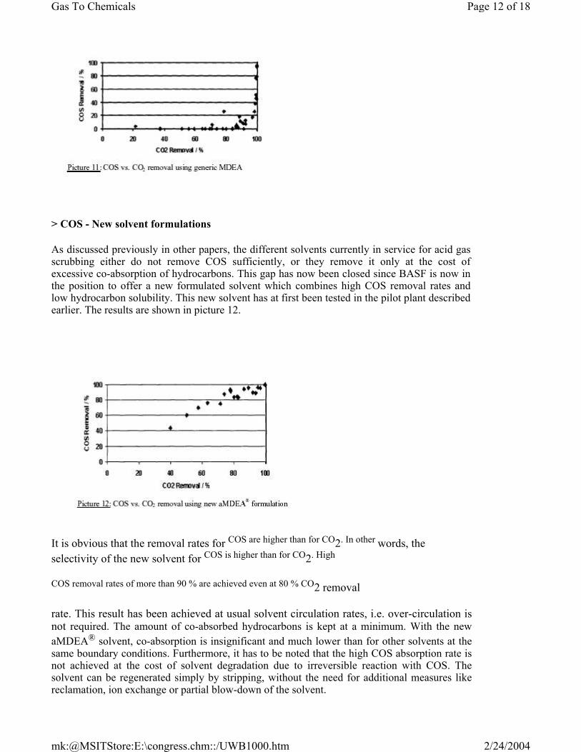
Up to a CO2 removal rate of 80 % the COS removal rate remains virtually zero (see picture 11). Only at very high
CO2 removal rates is the COS also removed to a
higher extent. As discussed above, with generic MDEA, a substantial CO2 removal
rate can only be achieved when the absorber is operated at a very high solvent circulation rate. This, on the other hand, allows the removal of a large part of the COS simply by physical absorption. The result achieved with generic MDEA is very well in accordance with the theory on physical absorption. The high COS
absorption rate should have been at the cost of high co-absorption rates for C3 and
higher compounds. At the same time the increased solvent circulation rate leads to an uneconomical high energy demand.
Page 11 of 18Gas To Chemicals
2/24/2004mk:@MSITStore:E:\congress.chm::/UWB1000.htm
> COS - New solvent formulations
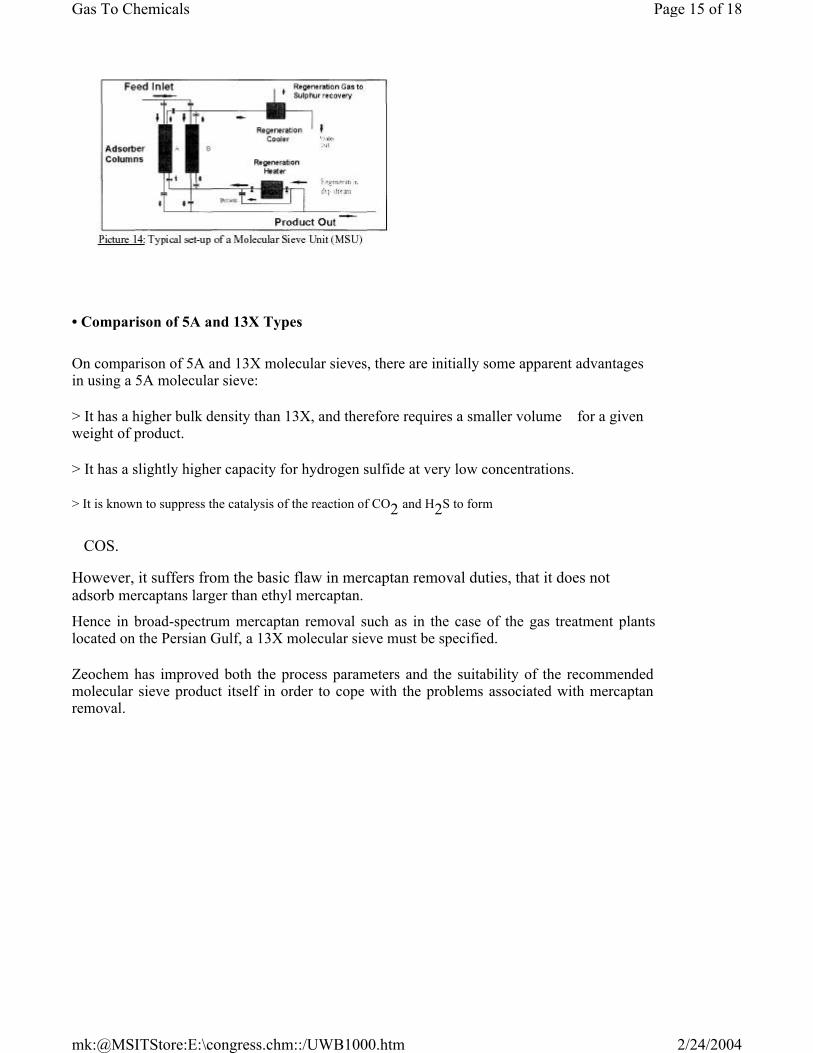
As discussed previously in other papers, the different solvents currently in service for acid gas scrubbing either do not remove COS sufficiently, or they remove it only at the cost of excessive co-absorption of hydrocarbons. This gap has now been closed since BASF is now in the position to offer a new formulated solvent which combines high COS removal rates and low hydrocarbon solubility. This new solvent has at first been tested in the pilot plant described earlier. The results are shown in picture 12.
It is obvious that the removal rates for COS are higher than for CO2. In other words, the selectivity of the new solvent for COS is higher than for CO2. High
COS removal rates of more than 90 % are achieved even at 80 % CO2 removal
rate. This result has been achieved at usual solvent circulation rates, i.e. over-circulation is not required. The amount of co-absorbed hydrocarbons is kept at a minimum. With the new aMDEA® solvent, co-absorption is insignificant and much lower than for other solvents at the same boundary conditions. Furthermore, it has to be noted that the high COS absorption rate is not achieved at the cost of solvent degradation due to irreversible reaction with COS. The solvent can be regenerated simply by stripping, without the need for additional measures like reclamation, ion exchange or partial blow-down of the solvent.
Page 12 of 18Gas To Chemicals
2/24/2004mk:@MSITStore:E:\congress.chm::/UWB1000.htm

> COS - Experience
The new solvent was first applied in a full-scale plant when a solution swap was carried out in two parallel trains of a gas plant in Canada (picture 13).
The plant suffered from unsatisfactory trace sulfur removal, and severe corrosion was a further problem. Before the solution swap the two units had been operated with an amine-based solvent. Several additives had been tried in order to improve the trace sulfur removal rate. However, the only effect of these additives, if any, was an increase of hydrocarbon co-absorption. The sulfur specification could not be met. Finally the solution was exchanged against the new aMDEA® solvent from BASF. Prior to start-up the operating conditions of the plant were thoroughly calculated. The set points of the control systems were adjusted in order to get the greatest benefit from the unique features of the new solvent. Then the solvent circulation was established and gas was fed to the system. Right from the beginning the total sulfur specification was met. Gas samples were taken from the feed gas and treated gas, and the results of the analysis show, that almost 99 % of the COS present in the feed gas is removed. This result could be achieved at a fairly low solvent circulation rate. The acid gas loading of the rich solution in this very case was as high as 0.58 moles of acid gas per mole of amine. This figure is by far higher than what is possible with competing solvents, even when no COS removal is required or achieved. In the meantime, the acid gas loading figures are even higher after fine-tuning of the operating parameters.
Since no over-circulation is required, it is no wonder that co-absorption of
hydrocarbons is not an issue. The co-absorption rate for hydrocarbons C1 to C5 in
this very case is only in the range of 0.3%, i.e. only about 0.3% of the hydrocarbons contained in the gas to be treated are absorbed. The respective figures for amine systems with physical additives would be in the range of 2 to 20%, whereby the higher figures apply for the longer chained hydrocarbons.
Page 13 of 18Gas To Chemicals
2/24/2004mk:@MSITStore:E:\congress.chm::/UWB1000.htm

ZEOCHEM's developments in gas-phase Mercaptane removal
• Zeolite in natural gas service Both 13X and 5A molecular sieves have traditionally been used for a variety of desulphurising duties, where very low levels of residual sulfur compounds are required in the outlet stream. However it has been argued that there are no "World-Scale" plants operating with such technology. Further, experience has shown a short lifetime for molecular sieves in such applications. Zeochem technology has evaluated process and laboratory results and has modified process parameters to enable such plants to operate economically. Molecular sieves have been used on many regenerative applications over the last thirty years. They are generally used in applications where very low outlet concentrations are required.
Typical simple examples are:
Moisture Removal
E.g. natural gas dehydration, LNG plants, ethylene crackers, industrial gases
CO2 removal
E.g. air pre-purification plants for the cryogenic separation of air
Hydrogen sulfide / mercaptan removal
E.g. many liquid phase and several gas phase units.
While moisture removal is traditionally done with the smaller pore-sized 3A and 4A molecular sieves the
CO2 removal and sulfur removal duties are done using the larger pore 5A and 13X types of molecular sieve.
Page 14 of 18Gas To Chemicals
2/24/2004mk:@MSITStore:E:\congress.chm::/UWB1000.htm
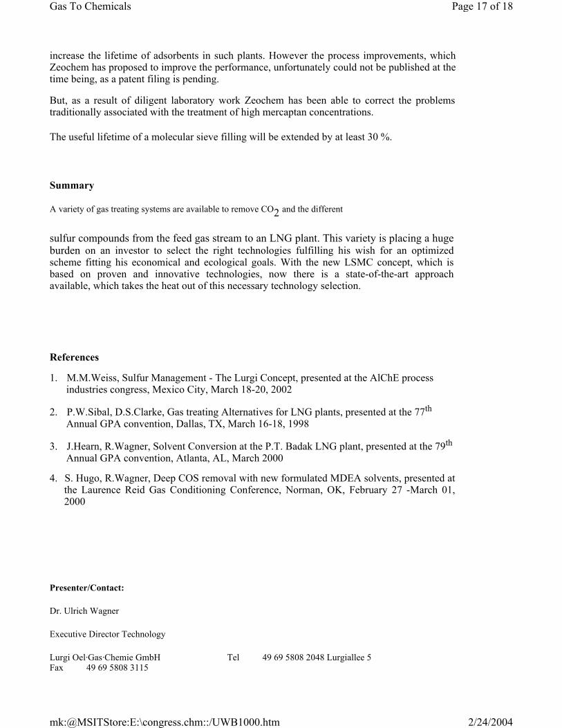
• Comparison of 5A and 13X Types
On comparison of 5A and 13X molecular sieves, there are initially some apparent advantages in using a 5A molecular sieve:
> It has a higher bulk density than 13X, and therefore requires a smaller volume for a given weight of product.
> It has a slightly higher capacity for hydrogen sulfide at very low concentrations.
> It is known to suppress the catalysis of the reaction of CO2 and H2S to form
COS.
However, it suffers from the basic flaw in mercaptan removal duties, that it does not adsorb mercaptans larger than ethyl mercaptan. Hence in broad-spectrum mercaptan removal such as in the case of the gas treatment plants located on the Persian Gulf, a 13X molecular sieve must be specified.
Zeochem has improved both the process parameters and the suitability of the recommended molecular sieve product itself in order to cope with the problems associated with mercaptan removal.
Page 15 of 18Gas To Chemicals
2/24/2004mk:@MSITStore:E:\congress.chm::/UWB1000.htm

• Liquid vs. gas-phase application
Zeochem produces many hundreds of tons a year of 13X molecular sieve for regenerative applications, and thus has much experience in many of the applications for this product.
Zeochem routinely supplies 13X molecular sieve to many sweetening duties around the world. These plants vary in size from larger scale plants operating on refineries, gas plants etc, to small scale plants operating bottling plants or can filling operations. Many of these operations are liquid phase operations and the adsorption process shows much slower kinetics in comparison to gas phase operations. They are therefore more difficult to run effectively than gas phase
plants. In BOTH cases, the regeneration phase is carried out in the same way, i.e. by heating the molecular sieve adsorbent in a dry hydrocarbon gas stream. Hence this part of the process is identical whether gas or liquid phase adsorption takes place. The only difference in the process steps is that liquid phase operations require emptying and refilling steps in addition.
• Enhanced lifetime development
While Zeochem has undertaken much development work over the last ten years, and has improved the capacity of its 13X by 20 plus percent, it is the kinetics, i.e. the rate at which adsorption occurs, which also makes it a preferred adsorbent.
The problems are associated with the short lifetime of molecular sieves in gas phase applications of mercaptan removal, i.e. coking of the molecular sieve during the regeneration, causing a loss of capacity and early change-out of the filling.
Zeochem has undertaken much laboratory work to back up their industrial experiences, and to help develop molecular sieve optimized for mercaptan removal processes. Laboratory work is generally done at a lower breakthrough capacity of 0.1 ppm, rather than the 1 ppm level specified under plant conditions. Hence quoted capacities may be low compared to plant use.
The key issue is not whether 5A or 13X molecular sieve is used, but the main point of interest is the regeneration stage of the process. Zeochem is now proposing a modified technology to
Page 16 of 18Gas To Chemicals
2/24/2004mk:@MSITStore:E:\congress.chm::/UWB1000.htm
increase the lifetime of adsorbents in such plants. However the process improvements, which Zeochem has proposed to improve the performance, unfortunately could not be published at the time being, as a patent filing is pending.
But, as a result of diligent laboratory work Zeochem has been able to correct the problems traditionally associated with the treatment of high mercaptan concentrations.
The useful lifetime of a molecular sieve filling will be extended by at least 30 %.
Summary
A variety of gas treating systems are available to remove CO2 and the different
sulfur compounds from the feed gas stream to an LNG plant. This variety is placing a huge burden on an investor to select the right technologies fulfilling his wish for an optimized scheme fitting his economical and ecological goals. With the new LSMC concept, which is based on proven and innovative technologies, now there is a state-of-the-art approach available, which takes the heat out of this necessary technology selection.
References
1. M.M.Weiss, Sulfur Management - The Lurgi Concept, presented at the AlChE process industries congress, Mexico City, March 18-20, 2002
2. P.W.Sibal, D.S.Clarke, Gas treating Alternatives for LNG plants, presented at the 77th Annual GPA convention, Dallas, TX, March 16-18, 1998
3. J.Hearn, R.Wagner, Solvent Conversion at the P.T. Badak LNG plant, presented at the 79th Annual GPA convention, Atlanta, AL, March 2000
4. S. Hugo, R.Wagner, Deep COS removal with new formulated MDEA solvents, presented at the Laurence Reid Gas Conditioning Conference, Norman, OK, February 27 -March 01, 2000
Presenter/Contact:
Dr. Ulrich Wagner
Executive Director Technology
Lurgi Oel·Gas·Chemie GmbH Tel 49 69 5808 2048 Lurgiallee 5 Fax 49 69 5808 3115
Page 17 of 18Gas To Chemicals
2/24/2004mk:@MSITStore:E:\congress.chm::/UWB1000.htm
60295 Frankfurt, Germany Email [email protected]
Page 18 of 18Gas To Chemicals
2/24/2004mk:@MSITStore:E:\congress.chm::/UWB1000.htm