suitability of uml4odp for an engineering specification … higher institute of technology of...
TRANSCRIPT

14th
LACCEI International Multi-Conference for Engineering, Education, and Technology: “Engineering Innovations for
Global Sustainability”, 20-22 July 2016, San José, Costa Rica.
Suitability of UML4ODP for an Engineering Specification of a
Distributed Environment for Teaching Embedded Systems
Mohamed Mhamdi, Technologist Professor 1, Hamadou Saliah-Hassane, Senior IEEE Member2
Rafik Braham, Professor3, Wahid Bannour, Technologist Lecturer4 1 ISET, Higher Institute of Technology of Sousse, Tunisia, [email protected]
2 TELUQ, University of Quebec, Canada, [email protected] 3 PRINCE Research Unit of Sousse, Tunisia, [email protected]
4 ISET, Higher Institute of Technology of Mahdia, Tunisia, [email protected]
Abstract– In this paper, we will contribute to an engineering
specification of a distributed environment that will help to generate
remote Lab work supports for teaching embedded systems. Our
main objective is to show the appropriateness of adopting the ODP-
RM (Open Distributed Processing - Reference Model) model
proposed by the ISO (International Organization for
Standardization) to express the specification of our environment
from an engineering point of view. By choosing the UML4ODP
language that comprises all the ODP-RM concepts to express the
specification of such point of view we will try to specify our
environment as a distributed system composed of a set of objects
and that support the necessary mechanisms and functions for their
distributed interactions. Software architecture styles, such as SOA,
MVC and N-tier, are considered in our engineering specification,
since they are closely related to the distribution strategy. Keywords-
- ODP-RM, UML4ODP, Distributed Environment, Remote lab
work, Online laboratory.
Digital Object Identifier (DOI):
http://dx.doi.org/10.18687/LACCEI2016.1.1.383
ISBN: 978-0-9822896-9-3
ISSN: 2414-6390

14th LACCEI International Multi-Conference for Engineering, Education, and Technology: “Engineering Innovations for
Global Sustainability”, 20-22 July 2016, San José, Costa Rica. 1
Suitability of UML4ODP for an Engineering Specification of a Distributed Environment
for Teaching Embedded Systems
Mohamed Mhamdi, Technologist Professor 1, Hamadou Saliah-Hassane, Senior IEEE Member2
Rafik Braham, Professor3, Wahid Bannour, Technologist Lecturer4
1 ISET, Higher Institute of Technology of Sousse, Tunisia, [email protected] 2 TELUQ, University of Quebec, Canada, [email protected]
3 PRINCE Research Unit of Sousse, Tunisia, [email protected] 4 ISET, Higher Institute of Technology of Mahdia, Tunisia, [email protected]
Abstract– In this paper, we will contribute to an engineering
specification of a distributed environment that will help to generate
remote Lab work supports for teaching embedded systems. Our
main objective is to show the appropriateness of adopting the ODP-
RM (Open Distributed Processing - Reference Model) model
proposed by the ISO (International Organization for
Standardization) to express the specification of our environment
from an engineering point of view.
By choosing the UML4ODP language that comprises all the
ODP-RM concepts to express the specification of such point of view
we will try to specify our environment as a distributed system
composed of a set of objects and that support the necessary
mechanisms and functions for their distributed interactions.
Software architecture styles, such as SOA, MVC and N-tier,
are considered in our engineering specification, since they are
closely related to the distribution strategy.
Keywords-- ODP-RM, UML4ODP, Distributed Environment,
Remote lab work, Online laboratory.
I. INTRODUCTION
This work presents original and innovative ways of
considering research axes on Online Laboratories based on the
acquired experience within the framework of two projects
carried on at LICEF Research Center in Montreal: LORNET
and EduSource projects.
The main goal of the EduSource project was to create a
repository of interoperable networked learning objects. In the
framework of LORNET project, laboratory components as
learning objects stored in repositories was presented in [1].
One of LORNET project’s goal was to define a generic
concept of an online laboratory allowing students to realize
practical works remotely and as well as in collaboration. This
generic architecture is based on the specification defined by
most known e-learning standards. It is also based on the use of
ontological model to describe the controlled devices of the
embedded automated systems.
We recall that the main objective of this paper is to
perform, based in the ODP- RM (Open Distributed Processing
- Reference Model) [2], an engineering specification of a
distributed environment that will help to generate distance lab
work or Remote lab work supports for teaching embedded
systems. We called this environment "a Tele-LabWork System
Environment Generator for Teaching Embedded System" or
"TeleLWS_EG", for short.
Three Software architecture styles (N-tier, MVC, SOA)
related to the distribution aspect of the TeleLWS_EG will be
considered by our engineering specification as follows [3]:
1) The Presentation: The TeleLWS_EG will be
presented as a 4-tier distributed system.
2) The interaction: The interaction aspect of
TeleLWS_EG will be modeled according to a MVC
architecture.
The embedded platform that represents the central
element of the remote lab work activities will be accessible via
the services of a SOA architecture. As shown in Fig. 1, this
platform is composed of a remote embedded control devices
combined with a 3D representation of an operative part of an
automated system [4].
The second section of this paper gives an overview of the
engineering specification of the TeleLWS_EG in UML4ODP.
The third section focuses on the node configuration model
used to deploy the TeleLWS_EG.
The forth section concentrates on the description of the
node structures of this configuration model in terms of Basic
Engineering Objects (BeOs).
Fig. 1: The Labwork embedded platform.
Network
Student
Student
Teacher
µC
PLC
Real part of the
Command part platform
Virtual part of the
Operative part platform
Digital Object Identifier (DOI): http://dx.doi.org/10.18687/LACCEI2016.1.1.383ISBN: 978-0-9822896-9-3ISSN: 2414-6390
14th LACCEI International Multi-Conference for Engineering, Education, and Technology: “Engineering Innovations for
Global Sustainability”, 20-22 July 2016, San José, Costa Rica. 2
II. AN OVERVIEW OF THE ENGINEERING SPECIFICATION OF
THE TELELWS_EG IN UML4ODP
The engineering language of the ODP model will enable
us to express an engineering specification that will define the
functions and the mechanisms required to support the
execution and the distributed interaction between the
engineering objects of the TeleLWS_EG system.
From an engineering point of view, our system
TeleLWS_EG will be specified as a distributed application
composed of a set of basic engineering objects interacting via
communication channels. The concepts of this language are:
node (computer), kernel (operating system), capsule (address
space) and cluster (modules linked to form an executable) and
object engineering (program module).
All these concepts that express the engineering
specification will be defined in a model, stereotyped as
"Engineering_Spec" and written in the UML4ODP language
[2].
Table 1 shows the schematic profile UML4ODP that
summarizes the UML extensions for engineering language of
the ODP_RM model.
To improve the clarity of the diagrams in this paper, the
icons shown in this table will be used to represent the instances
of the corresponding stereotypes.
TABLE I
ENGINEERING LANGUAGE ICONS
«NV_Object» «NV_ClusterManager»
«NV_BEO» «NV_CapsuleManager»
«NV_TypeObject» «NV_Nucleus»
«NV_TemplateObject» «NV_CommunicationAu
thority»
«NV_Checkpoint» «NV_Channel»
«NV_ClusterCheckpoint» «NV_Stub»
«NV_Cluster» «NV_Binder»
«NV_Capsule» «NV_Interceptor»
«NV_Node» «NV_ProtocolObject»
«NV_CommunicationDomain»
«NV_ InterfaceReferenceManagementDomain »
III. NODE CONFIGURATION MODEL
Like many standards our TeleLWS_EG distributed system
for the development and execution of remote laboratory
activities supports data persistence, transactions, security and
business processing.
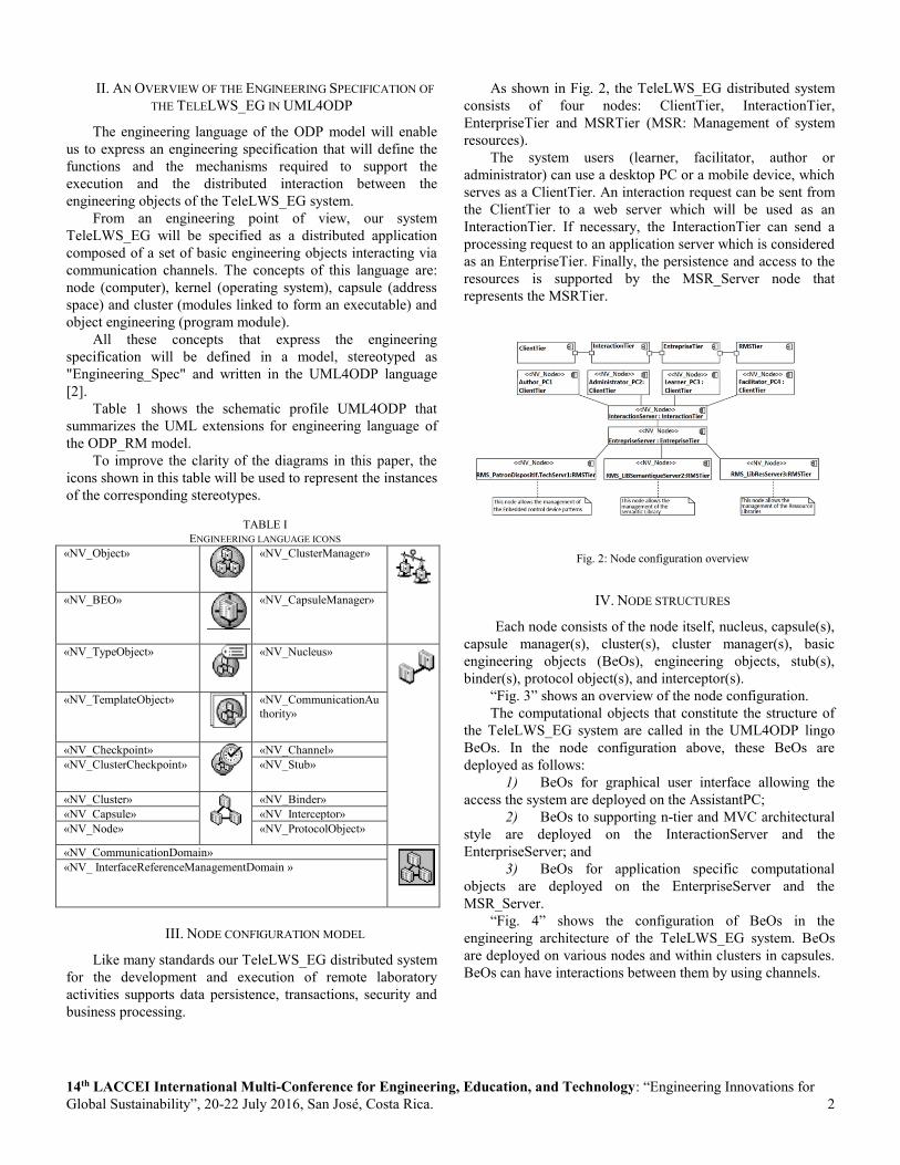
As shown in Fig. 2, the TeleLWS_EG distributed system
consists of four nodes: ClientTier, InteractionTier,
EnterpriseTier and MSRTier (MSR: Management of system
resources).
The system users (learner, facilitator, author or
administrator) can use a desktop PC or a mobile device, which
serves as a ClientTier. An interaction request can be sent from
the ClientTier to a web server which will be used as an
InteractionTier. If necessary, the InteractionTier can send a
processing request to an application server which is considered
as an EnterpriseTier. Finally, the persistence and access to the
resources is supported by the MSR_Server node that
represents the MSRTier.
Fig. 2: Node configuration overview
IV. NODE STRUCTURES
Each node consists of the node itself, nucleus, capsule(s),
capsule manager(s), cluster(s), cluster manager(s), basic
engineering objects (BeOs), engineering objects, stub(s),
binder(s), protocol object(s), and interceptor(s).
“Fig. 3” shows an overview of the node configuration.
The computational objects that constitute the structure of
the TeleLWS_EG system are called in the UML4ODP lingo
BeOs. In the node configuration above, these BeOs are
deployed as follows:
1) BeOs for graphical user interface allowing the
access the system are deployed on the AssistantPC;
2) BeOs to supporting n-tier and MVC architectural
style are deployed on the InteractionServer and the
EnterpriseServer; and
3) BeOs for application specific computational
objects are deployed on the EnterpriseServer and the
MSR_Server.
“Fig. 4” shows the configuration of BeOs in the
engineering architecture of the TeleLWS_EG system. BeOs
are deployed on various nodes and within clusters in capsules.
BeOs can have interactions between them by using channels.

14th LACCEI International Multi-Conference for Engineering, Education, and Technology: “Engineering Innovations for
Global Sustainability”, 20-22 July 2016, San José, Costa Rica. 3
Fig. 3 BeOs configuration of the TeleLWS_EG (Engineering_Spec).
For instance, Browser_APC1 BeO on AssistantPC1 node
communicates with Controller BeO on InteractionServer node
via Channel1.
In the following clauses of this section we will present with
more detail these BeOs by indicating the computational
objects that they support.
A. The BeOs of the ClientTier Node
The BeO that is deployed on the "ClientTier» node is
generally a GUI that allows the user to access to the
TeleLWS_EG system via an interaction object.
This BeOS integrates usually a thin client application
software which is extracted from the primary resource library
(tools, documents, software locally installed, web browser, or
applets Plugin) of the TeleLWS_EG system.
In the example shown by Fig. 5, this level consists of three
nodes that are used by the main users (administrator, facilitator
and learner) involved in the use and exploration of DLWMPrJ
(Distance Lab Work Management Project).
Depending on the equipment installed at the client node,
there is a wide variety of thin client software that can be used:
Fig. 4 Entreprise Internal Configuration Server.
we can use a web browser with a standard desktop as we can
use a wireless internet browser (WIB), supporting Wireless
Markup language (WML) with a mobile device Like a
Personal Digital Assistant (PDA).
Fig. 5: Mobile Client node based on a two BeOs supporting a Wireless
Internet Browser and a VRML Viewer.

14th LACCEI International Multi-Conference for Engineering, Education, and Technology: “Engineering Innovations for
Global Sustainability”, 20-22 July 2016, San José, Costa Rica. 4
In a very particular context related to the teaching of the
automated system the browser of the client node is requested
to visualize the virtual mechanical part of the DLWMPrJ
platform using a "3D viewer". This virtual mechanical part
which is modeled in a 3D language (VRML) as a modular
robot will be combined via a communication protocol with a
real embedded control device during handling of the platform
of TP@D.
B. The BeOs of the InteractionServer Node
The BeOs that represent the presentation objects and that
support the MVC architectural model are deployed on two
nodes: the InteractionServer and The EnterpriseServer nodes.
The system functions related to the presentation and to the
interaction with the user and that must be provided by the
TeleLWS_EG system are assigned to this type of BeOS.
These BeOs allow the user to interact with the business objects
in a secure and intuitive manner.
An interaction object is in fact an aggregation which is
composed of three types of objects according to the MVC
Model (Model-View-Controller): the controller object, the
model object and the view object.
The controller is a control object which is always coupled
to a view object. It handles user requires coming from the
client workstations and orders a business or a model object to
respond to the user's request appropriately.
For example, a learner who wants to look for a learning
object representing a pattern of one of the components of the
distance lab work platform can use a GUI provided by an
interaction object to perform this research.
The interaction object submits this order to a business
object, which checks the platform’s components pattern
libraries that are available via a manager object that performs
the necessary functions for accessing and sending.
Once the user request was processed, the system can
provide various views. The current examples are:
1) A GUI displaying a 3D learning Robot to be
manipulated by the learner as shown by Fig. 6;
2) A GUI showing the virtual control device that will be
programmed by the learner.
Fig. 6: The view of the BeO supporting the DLWMPrJ interactive
Environment delivered by the InteractionServer Node.
C. The BeOs of the EnterpriseTier Node
The BeOs corresponding to the business computational
objects and the interfaceGRS’s manager objects are deployed
on the EnterpriseServer node.
1) The "EnterpriseTier" includes Enterprise components
that represent the business logic of the TeleLWS_EG system.
2) The system calls to these objects are performed by the
ClientTier via the InteractionTier (WebTier).
3) If necessary the EnterpriseTier interchanges with the
recording layer (RMS: Resources Management System) to
access to the resources invoked by the said calls. These
business objects are responsible the production system of the
TeleLWS_EG’s aggregation resources that are organized in
four levels of a cascaded architecture [5] as shown in Fig. 7.
These objects are particularly global: The first level of this
production cascade which is represented by the basic system
"TeleLWS_EG Core" allows us to produce the objects of the
second level. These ones are really a set of distance labwork
platforms and they are technically known as DLWMS
(Distance Labwork Management System). The DLWMS are
used to generate the objects of the third level of our cascade
that are called DLWMPrJs (Distance Labwork Management
Project). The DLWMPrJ which is an application software used
as an environment to remotely practice Lab works on
embedded system. It is used to produce a set of aggregated
products that will constitute the fourth level of the cascade.
These products are the results of the practice activities
performed by the different actors concerned by the execution
of the DLWMPrJ [6]. These products are assembled in a set of
portfolios (portfolio) or DLWMPrDs (distance Labwork
Management Product).
Fig. 7: The four levels of the TeleLWS_EG’s cascaded architecture.
D. The BeOs of the RMS_Server Nodes
The BeOs corresponding to the computational objects of
the library managers are deployed on the RMS_Server nodes.
The RMSTier level (Resource Management System Tier)
allows the enterprise objects to be independent from the
library and the physical resources of the system.
This level of the network architecture includes three nodes:
14th LACCEI International Multi-Conference for Engineering, Education, and Technology: “Engineering Innovations for
Global Sustainability”, 20-22 July 2016, San José, Costa Rica. 5
1) The first node is used to deploy the managers of the
different types of the resource libraries that contain the entire
information system of the TeleLWS_EG, except the managers
of the embedded system control devices that are deployed on
another node. These libraries include different types of
resource aggregations [5] [6]: 1) the primary resource libraries
include documents and tools (D, T), Users (U) and operations
(O). A simple text editor that lets create a control code to be
executed by the control device can be among the tools of these
libraries; 2) the secondary resource libraries comprises the
interfaced resources (the interaction objects) resulting from the
combination of a control component or a HMI with a primary
resource or from the aggregation of primary or interfaced
resources; The four types of HMI (Assembly O.P Diagram
HMI, Datalink Map Connection HMI, Programming HMI and
Cosimulation HMI modelling) that we have developed and that
constitute the modelling and simulating system of the 3D Web
Based robots that are coupled with control devices to teach
embedded systems, can be considered as secondary resources;
3) the tertiary resource libraries grouping the most important
enterprise objects of our TeleLWS_EG system: Core system,
DLWMS, DLWMPrJ and DLWMPrD.
2) A second node for managing the semantics library of
the TeleLWS_EG system. This node contains several semantic
repository managers.
The mainly managers that are deployed on that node are those
of ontologies [7] written in SOCOM (Software Component
Metadata).
We have adopted this semantic representation to construct the
semantic repositories that describe the system resources and
their administrative and technical context of use.
One of the specific ontology that was used has been defined as
spatiotemporal patterns [2] which combines the concepts of
SOCOM [7] and MADS [8] formalism to describe a 3D
Semantic Data Library that produce descriptions of 3D robots
for distance Labwork.
3) A third node for the management of the control
devices embedded systems: due to many reasons related to the
genericity of the distance labwork scenarios and to the
specificities that characterize access to the control component
of the embedded automated systems, we have chosen to deploy
their manager on an independent node.
In fact, the manager of these devices is a very specific tool that
ensures mainly the functions of referencing, research and
access to these control components.
The Control devices of the embedded automated systems, are
declared in the Labwork scenarios of our Generic
environments (PLC, microcontroller etc.) as Universal
Resource Locators (URLs) to the desired devices like any
other object (document, script, etc.) on the Web [9].
To ensure the genericity of these scenarios, it is necessary that
these URLs localize the control devices and their expected
functionalities and not the address of the labwork platform
server because in this case the scenario would be specific to a
single labwork platform in the world.
It is possible to achieve this objective, through the use of an
embryonic ontology that we have built to describe the
components of a real control device associated with their
functionalities.
This ontology that we have built is an extension of the
metadata specification SOCOM defined in [5] for the
referencing of the software components.
Once a new type of a control device or an extension of an
existing type is physically installed, the administrator of the
labwork platform uses Control device Interface Management
Tool to declare it as the device access server by creating a new
pattern or, a pattern derived from an existing pattern (to limit
the declaration of additional components and functionalities)
and thus make it available to users.
Once the pattern is created, the administrator must declare (by
using the manager) the links between the functionalities
described by the pattern and the physical hardware
components (for example, the functionality "Load program" of
the component "microcontroller" is associated with the URL
"http://41.229.255.197:8080/FournisseurService/NIcRio9025/
UC/Load" of the control unit of the device "microcontroller
National Instrument cRIO-9022" [10]).
The SOA (Service Oriented Architecture) architecture based
on the JNI (Java Naming Interface) technology shown in Fig. 8
is proposed for the implementation and integration of
distributed embedded control devices whose components and
services are accessible via the device access server. We will
adopt this architecture to describe a thin environment (the
device access server) for exploration and use of services that
represent fast connectable embedded control devices [11].
Fig. 8: Embedded Control Device Access Server based on Jini
Technology.
V. CONCLUSION
This paper has discussed the specification of the
TeleLWS_EG’s system from an ODP engineering point of
view. In the ongoing work we will describe the implementation
of the TeleLWS_EG’s system from an ODP technological
point of view. This point of view ODP will allow us to
describe the realization of the TeleLWS_EG system in terms
of technological object configuration that represents hardware,
software and network components of the system. We believe

14th LACCEI International Multi-Conference for Engineering, Education, and Technology: “Engineering Innovations for
Global Sustainability”, 20-22 July 2016, San José, Costa Rica. 6
that this paper is a valuable contribution for the IEEE-SA
P1876™ Working Group.
REFERENCES
[1] H. Saliah-Hassane, A. Kourri, I. De la Tejal, “Building a repository for
online laboratory learning scenarios”, Frontiers in Education Conference,
36th Annual Volume Issue 27-31, pp.19 – 22, October 2006.
[2] Information technology – Open distributed processing – Use of UML for
ODP system specifications, ITU-T, October 2014.
http://www.lcc.uma.es/~av/download/UML4ODP_IS_V2.pdf
[3] M. Mhamdi, H. Saliah-Hassane and R. Braham, "Expressed in
UML4ODP: an Engineering Specification of a Distributed Environment
for Teaching Embedded Systems", ICEER2013 (International Conference
on Engeneering and Education and Research), Marrakech,Maroco,
Juillet, 2013.
[4] M.Mhamdi, R.Braham, M.Moalla, H.Saliah-Hassane, “A Virtual
Verification and Execution of Grafcet Using VRML”, Special
Volume:ENGINEERING EDUCATION AND RESEARCH, pp 381-389,
2004.
[5] A. Masmoudi, G. Paquette, R. Champagne, “Metadata-Based software
components repository’s reuse”, 3rd Annual Scientific Conference
LORNET Research Network, Montreal, Quebec, 2006.
[6] G. Paquette, F. Magnan, “An executable model for virtual campus
environments”, Handbook on Information Technologies for Education,
eds A. sberger, H. Heimo , K. Pawlowski, J. Martin, Springer. pp. 363-
403, 2008
[7] A. Masmoudi, et al. “Développement d'un scénario de laboratoire en
ligne par une agrégation de composants logiciels basée sur les
ontologies”, The 3rd International Symposium on Distance Education,
Tunisia, 2006.
[8] A.Vakaloudis, B. Theodoulidis, “Formalizing interactive behavior in 3D-
spatiotemporal worlds”, the working conference on advanced visual
interfaces, Palermo, Italy, 2000.
[9] A. Lelevé, H. Benmohamed, P. Prévôt, “Mise à distance de travaux
pratiques en automatique”, Revue Skholê: cahiers de la recherche et du
développement, Vol. 14, pp 87-99, 2008.
[10] User manual and specifications, Intelligent real-time embedded
controller for CompactRIO, NI. http://www.ni.com/pdf/manuals
/375102g.pdf
[11] F. Bouchaib, “Granularité et agrégation des interfaces graphiques de
laboratoires en ligne distribués”, Ecole de technologie de l’information,
Université du Québec, 2005.