subsea field development and production enhancement (ior) development.pdf · subsea field...
TRANSCRIPT

Subsea Field Development and Production Enhancement (IOR)
byJan O. HallsetTechnology DirectorPoseidon Group September 2009
Presented at Offshore Europe 2009 in Aberdeen
Poseidon Group
Specialists in subsea systems:Engineering & studiesSolutions & equipment packages (EPC)Installation & operational support
Key facts: Founded:2000Staff: 150 (2009)Turnover: 50 MUSD (2009E)Offices: Aberdeen, Stavanger
Visit us at: www.poseidongroup.co.uk
AberdeenStavanger
Slide Slide 22

A Subsea Field Development?
Slide Slide 33

Components in a Subsea Production System
Topsides Process
Well
Umbilical
Flowline
Reservoir
Manifold Well Head
Slide Slide 44
Platform
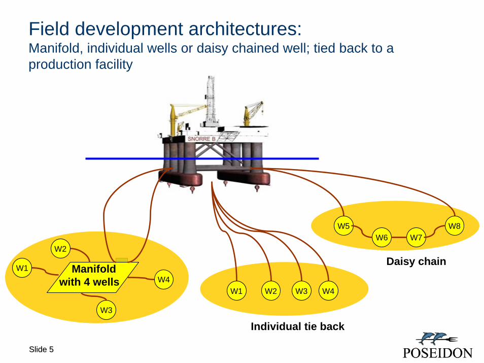
Field development architectures: Manifold, individual wells or daisy chained well; tied back to aproduction facility
W1 W2 W3 W4
W5W6 W7
W8
Daisy chain
Slide Slide 55
Individual tie back
W1
W2
W3
W4Manifold
with 4 wells
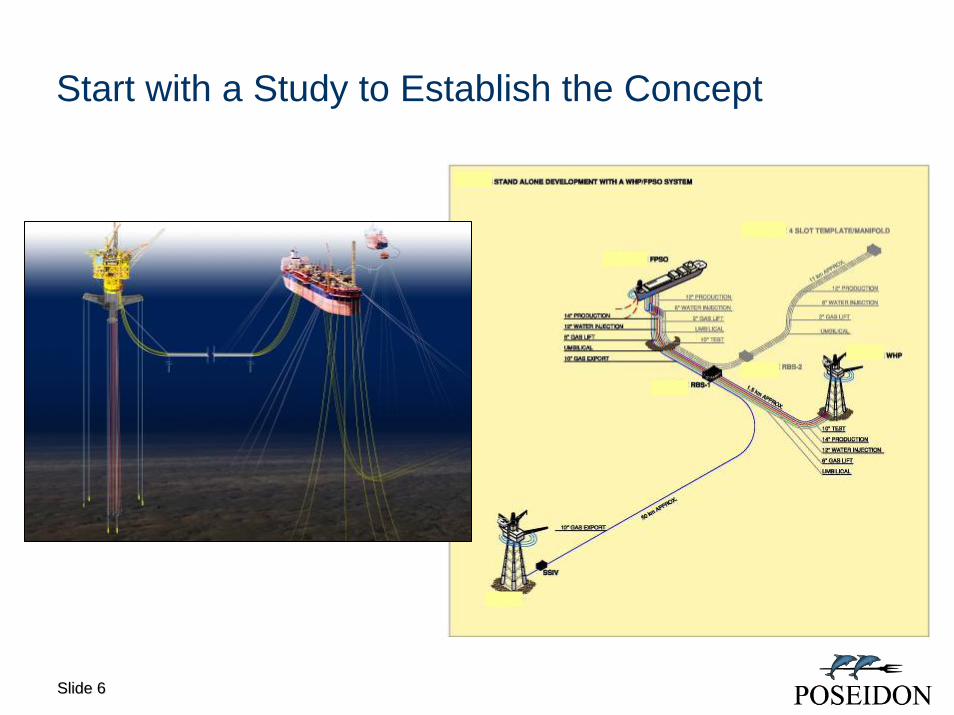
Start with a Study to Establish the Concept
Slide Slide 66

Girrasol(Total) : Well clusters with manifolds
Slide Slide 77
1400 meters depth

Ormen Lange (Shell): Long Step out / Deep Water
Slide Slide 88
Template B
Template A
PLET
42” export line
2 x 30” flow line2xMEG + 2x Umb
Shore terminal
120 km from land850 meters depth

What tools can be used for IOR (Increased Oil Recovery) given the typical production profile for gas/oil wells?
Slide Slide 99
Time
We want to lift the curve
Prod
uctio
n R
ate
Slide Slide 1010
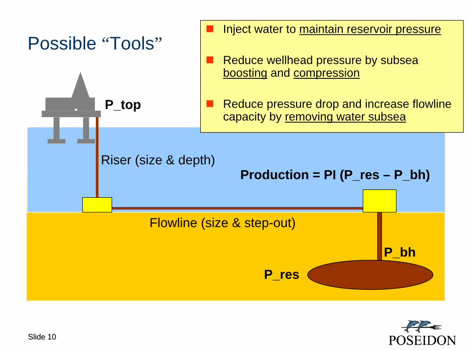
Possible “Tools”
Flowline (size & step-out)
Riser (size & depth)Production = PI (P_res – P_bh)
P_resP_bh
Inject water to maintain reservoir pressure
Reduce wellhead pressure by subsea boosting and compression
Reduce pressure drop and increase flowlinecapacity by removing water subsea
P_top
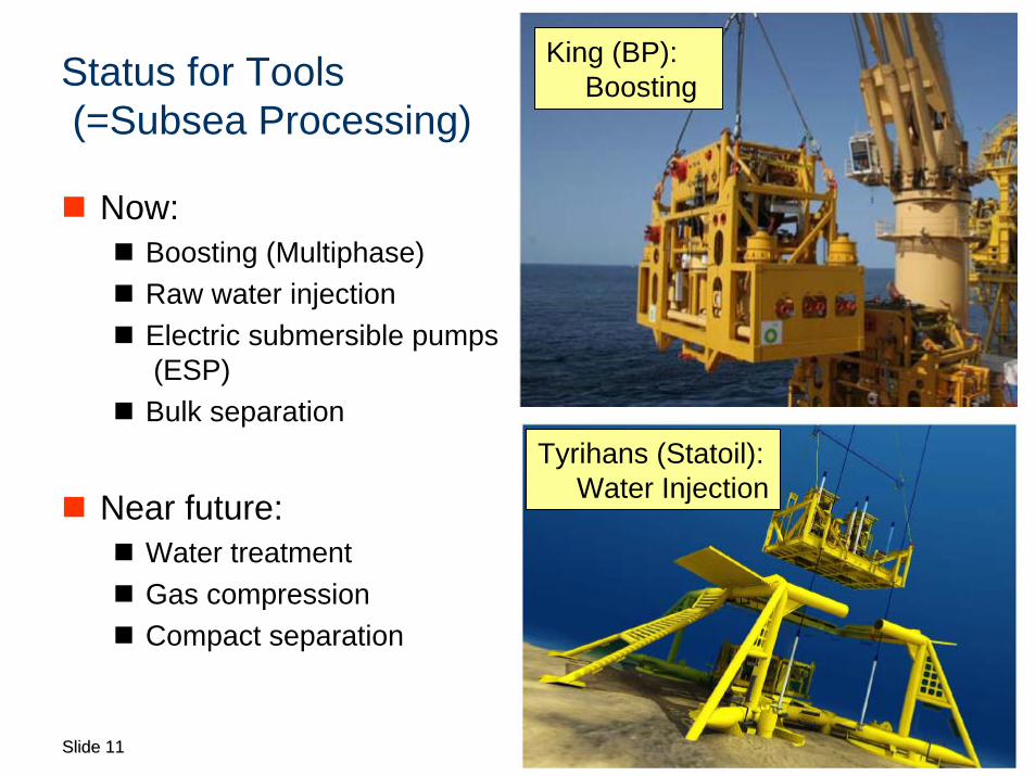
King (BP): BoostingStatus for Tools
(=Subsea Processing)
Now:Boosting (Multiphase)Raw water injectionElectric submersible pumps(ESP)Bulk separation
Near future:Water treatmentGas compressionCompact separation
Slide Slide 1111
Tyrihans (Statoil): Water Injection
Slide Slide 1212
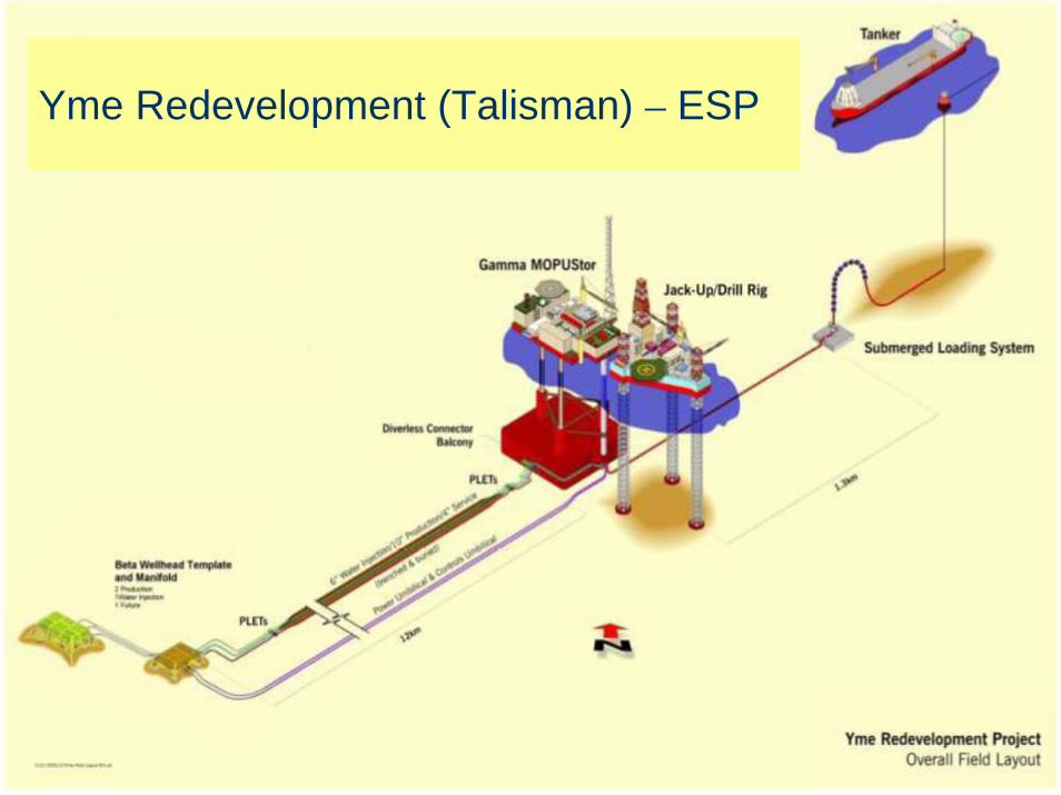
Yme Redevelopment (Talisman) – ESP
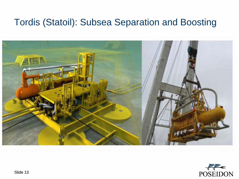
Tordis (Statoil): Subsea Separation and Boosting
Slide Slide 1313

Pazflor (Total): Subsea Separation and Boosting
Slide Slide 1414

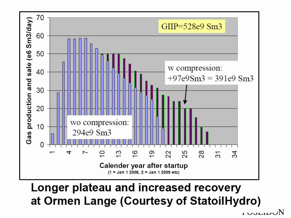
Ormen Lange (Shell): Subsea Compression
Length: 60m
Width: 38m
Height: 12m
Weight: 3,300 t
Slide Slide 1515
Slide Slide 1616
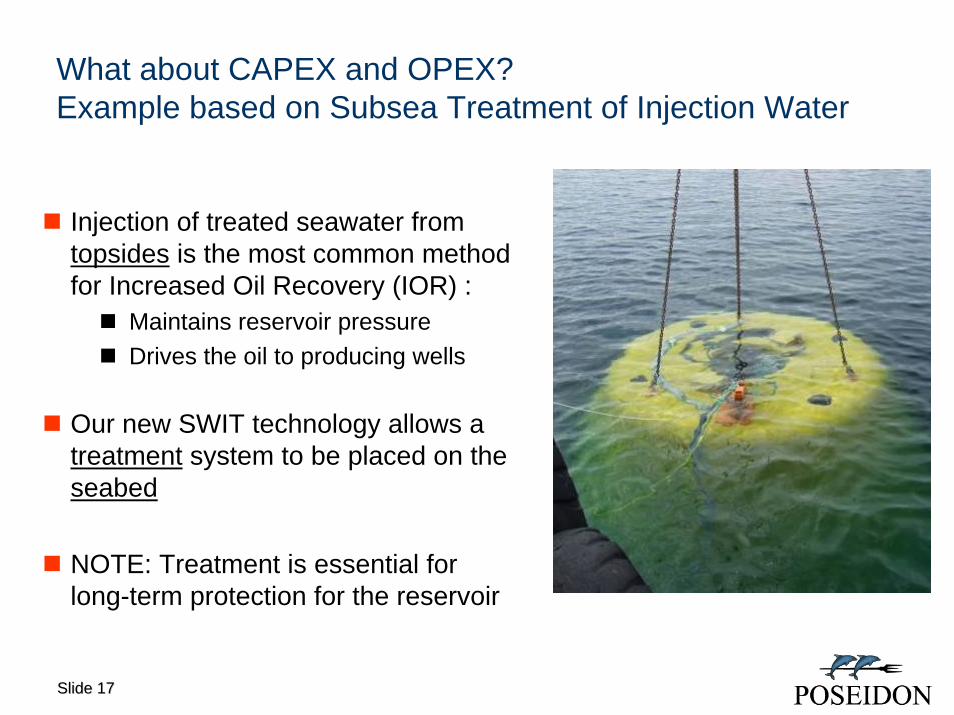
What about CAPEX and OPEX? Example based on Subsea Treatment of Injection Water
Injection of treated seawater from topsides is the most common method for Increased Oil Recovery (IOR) :
Maintains reservoir pressure Drives the oil to producing wells
Our new SWIT technology allows a treatment system to be placed on the seabed
NOTE: Treatment is essential for long-term protection for the reservoir
Slide Slide 1717
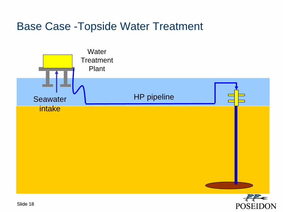
Base Case -Topside Water Treatment
Seawaterintake
HP pipeline
Water Treatment
Plant
Slide Slide 1818

SWIT Enables Seabed Based Water Treatment
SeawaterintakePower
cable
Save on major cost itemsTopside treatmentHP PipelineLow OPEXCAPEX when needed
SWIT
Slide Slide 1919
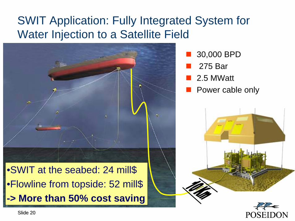
SWIT Application: Fully Integrated System for Water Injection to a Satellite Field
Slide Slide 2020
•SWIT at the seabed: 24 mill$•Flowline from topside: 52 mill$-> More than 50% cost saving
30,000 BPD 275 Bar
2.5 MWattPower cable only