submitting projects to the national geodetic survey for inclusion into the national spatial...
TRANSCRIPT

Submitting projects to the National Geodetic Survey for inclusion into the
National Spatial Reference System
[email protected],NGS State Advisor to
Maryland410.545.8963 (voice)
Blue Booking

OVERVIEW ( 1 of 2)
• Data must be submitted in digital form using NGS specified formats.
• Minimum accuracy order is 1st order horizontal and 2nd order vertical
• Data standards and accuracies must be verified by provider using NGS software.
• Monumentation must be uniquely identified and conform to NGS standards.

OVERVIEW (2 of 2)
• Original field records (or acceptable copies) must be submitted.
• Station descriptions must be provided using the NGS WDDPROC software.
• A project report and survey sketch are required.
• Users must submit a minimally constrained and a fully constrained adjustment.
Is there a fee?
• There is no charge for quality review, archiving and the distribution of data if the requirements are met.
• While the NGS project reviewers may fix minor errors in a project submission, they will return a project if numerous errors are found.

OVERVIEW
• Obtain software and documentation.• Prepare a plan and submit it to NGS.• Observe project according to plan.• Reduce observations to vectors.• Organize data and prepare needed files.• Perform adjustments (free and constrained)• Check project accuracies and write report.

Software You Need
• ELLACC• WDDPROC• ADJUST• CR8BB• BBACCUR• MODGEE• QQRECORD
• ELEVUP• MAKE86• COMPGB• CHKOBS• WCHKDESC• OBSDES•

Documentation

Documentation

Documentation

Documentation
Create an Observation Plan
• Complete station listing (new and existing)
• Sketch of network.
• Characteristics of monuments established.
• Occupation scheme (number and length of time)
• Intended accuracy.
• Types and number of instruments.

Submit Plan to NGS for Approval
• The NGS Project Development Branch must approve your plan.
• A response will be provided within 10 business days.
• Plans are reviewed for adherence to NGS published guidelines.

Observe Project
• Make observations according to the approved plan.
• Rubbings, photographs or detailed sketch are required of each point.
• Descriptions or recoveries are required for each point.
• Log sheets and obstruction diagrams are required for all points.

Reduce observations to vectors
• Perform data reductions using your software. Verify solutions are good.
• Either compute all possible baselines or the independent baselines only.
• For height modernization surveys use the specifications in TM 58.

Create Required Files
NGS program ADJUST uses three input files:B-File - station occupation records and station
a priori positionsA-File - adjustment parameters and
constraintsG-File – GPS vectors, standard deviations and
correlations.

INPUT FILES - “BLUE BOOK”
•Header Records (*10*, *12*, *13*)
•GPS Occupation Records (*25*, *27*)
•Instrument Records (*70*, *72*)
•Control Point Records (*80*)
•Height Record (*86*)

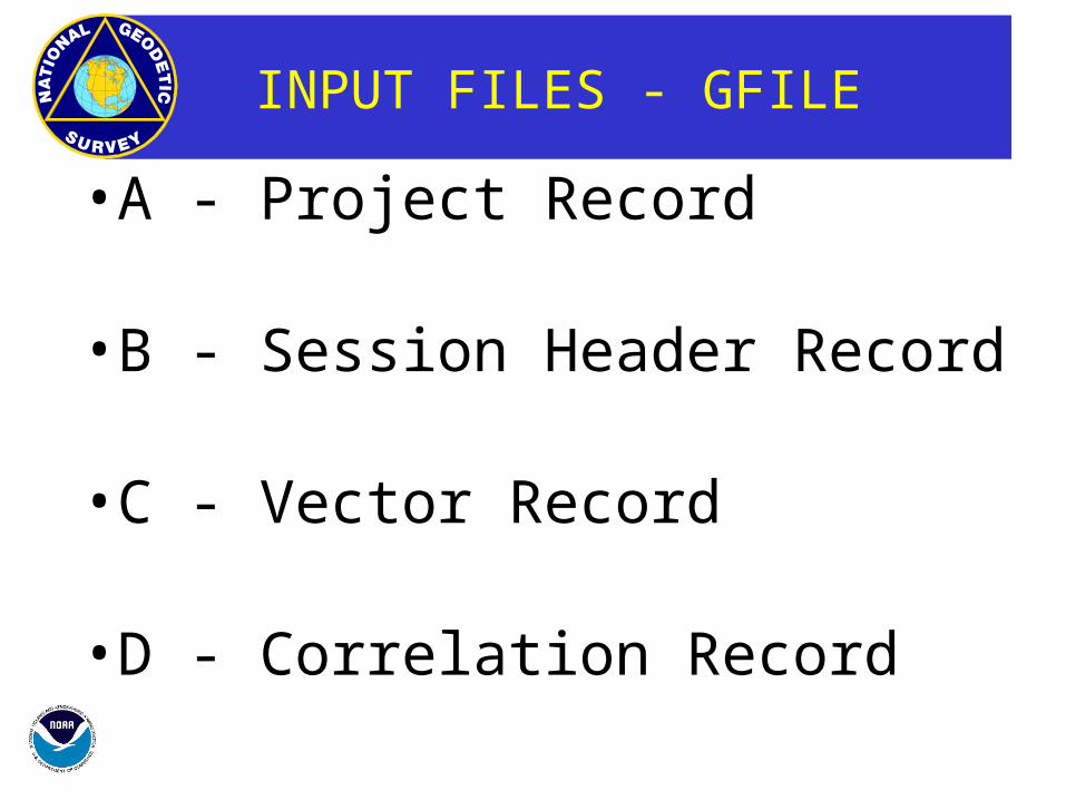
INPUT FILES - GFILE
•A - Project Record
•B - Session Header Record
•C - Vector Record
•D - Correlation Record
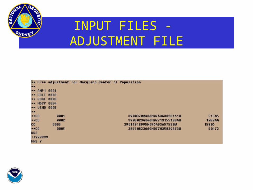
INPUT FILES - ADJUSTMENT FILE
•CC - Constrained Coordinate Record
•DD - Dimensionality Record
•II - Iteration Record
•MM - Adjustment Mode Record
•PP - Print Output Record
•QQ - Accuracy Computation Record

ADJUSTMENT FLOW
“Blue Book”
GFILE
AFILE
ADJUST
Adjusted“Blue Book”
AdjustmentOutput
VALIDITYCHECKINGPROGRAMS
Input Formats and Specifications of the National Geodetic SurveyData BaseVolume I. Horizontal Control ,Data
Silver Spring, MD 20910
September 1994
U.S. DEPARTMENT OF CommerceNational Oceanic and Atmospheric AdministrationNational Ocean ServiceCoast and Geodetic Survey

“INPUT FORMATS” TABLE OF CONTENTS
Chapter 1 - HORIZONTAL CONTROL (HZTL) DATA
Chapter 2 - HORIZONTAL OBSERVATION (HZTL OBS) DATA
Chapter 3 - GEODETIC CONTROL DESCRIPTIVE (GEOD DESC) DATA
ANNEX A - NGS STATE AND COUNTRY CODES
ANNEX B - STATE PLANE COORDINATES (SPC) ZONE CODES
ANNEX C - CONTRIBUTORS OF GEODETIC CONTROL DATA
ANNEX D - GUIDELINES FOR CONTROL POINT DESIGNATIONS
ANNEX E - STATIONS ORDER-AND-TYPE (OT) CODES
ANNEX F - NGS SURVEY EQUIPMENT CODES
ANNEX G - ELLIPSOID HEIGHT ORDER-AND-CLASS (OC) CODES
ANNEX H - STANDARD TIME ZONES
ANNEX I - SUMMARY OF CODES USED IN GEODETIC SURVEY POINT DEXCRIPTIONS
ANNEX J - GPS ANTENNA CODES (Superceded by ANNEX M)
ANNEX K - PROJECT REPORT INSTRUCTIONS
ANNEX L - GUIDELINES FOR SUBMITTING GPS RELATIVE POSITIONING DATA
ANNEX M - GPS ANTENNA CODES (This new annex supercedes ANNEX J)
ANNEX N - GLOBAL POSITIONING SYSTEM DATA TRANSFER FORMAT
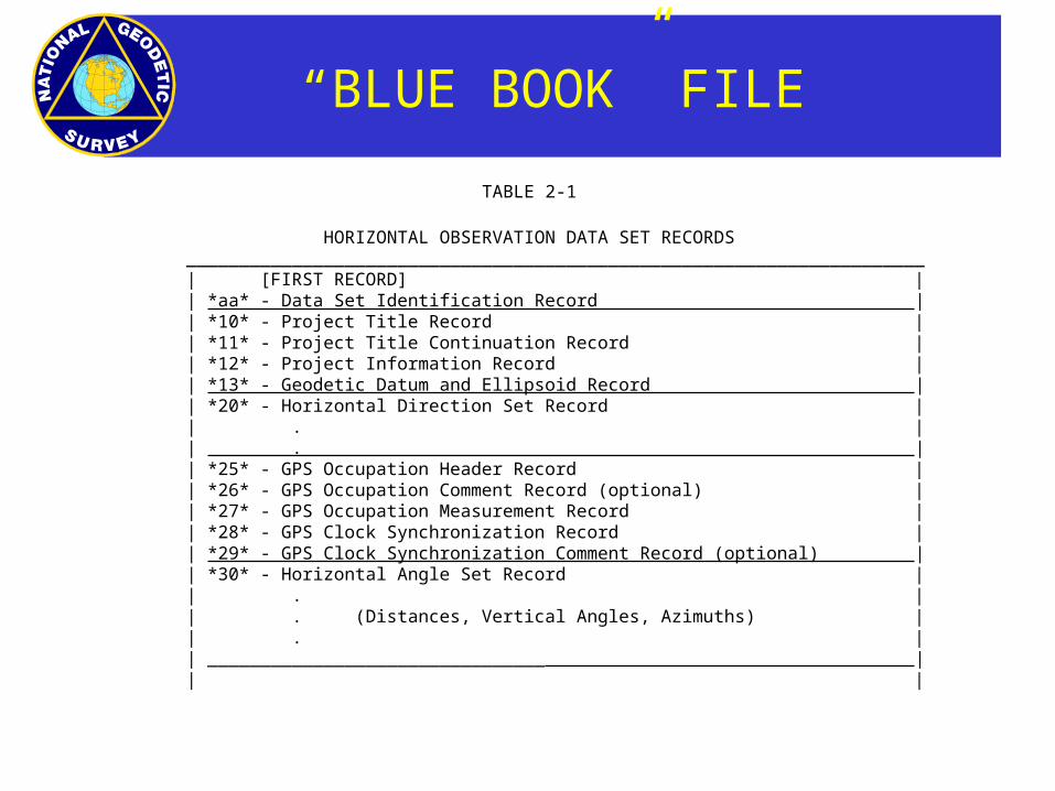
“BLUE BOOK” FILE
TABLE 2-1
HORIZONTAL OBSERVATION DATA SET RECORDS ______________________________________________________________________
| [FIRST RECORD] || *aa* - Data Set Identification Record || *10* - Project Title Record || *11* - Project Title Continuation Record || *12* - Project Information Record || *13* - Geodetic Datum and Ellipsoid Record || *20* - Horizontal Direction Set Record || . || . || *25* - GPS Occupation Header Record || *26* - GPS Occupation Comment Record (optional) || *27* - GPS Occupation Measurement Record || *28* - GPS Clock Synchronization Record || *29* - GPS Clock Synchronization Comment Record (optional) || *30* - Horizontal Angle Set Record || . || . (Distances, Vertical Angles, Azimuths) || . || ________________________________ || |
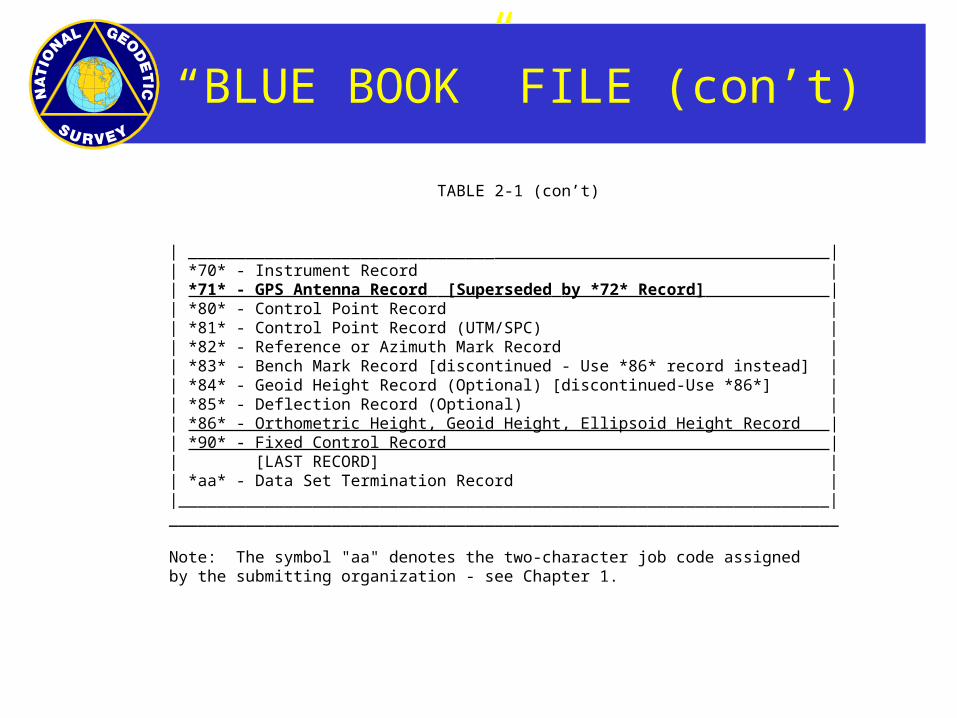
TABLE 2-1 (con’t)
| ________________________________ || *70* - Instrument Record |
| *71* - GPS Antenna Record [Superseded by *72* Record] | | *80* - Control Point Record |
| *81* - Control Point Record (UTM/SPC) || *82* - Reference or Azimuth Mark Record || *83* - Bench Mark Record [discontinued - Use *86* record instead] || *84* - Geoid Height Record (Optional) [discontinued-Use *86*] || *85* - Deflection Record (Optional) || *86* - Orthometric Height, Geoid Height, Ellipsoid Height Record || *90* - Fixed Control Record || [LAST RECORD] || *aa* - Data Set Termination Record ||____________________________________________________________________|______________________________________________________________________
Note: The symbol "aa" denotes the two-character job code assignedby the submitting organization - see Chapter 1.
“BLUE BOOK” FILE (con’t)
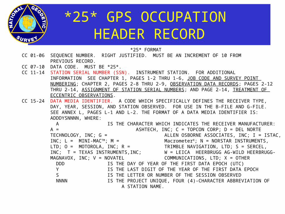
*25* GPS OCCUPATION HEADER RECORD
*25* FORMATCC 01-06 SEQUENCE NUMBER. RIGHT JUSTIFIED. MUST BE AN INCREMENT OF 10 FROM
PREVIOUS RECORD. CC 07-10 DATA CODE. MUST BE *25*.CC 11-14 STATION SERIAL NUMBER (SSN). INSTRUMENT STATION. FOR ADDITIONAL
INFORMATION SEE CHAPTER 1, PAGES 1-2 THRU 1-6, JOB CODE AND SURVEY POINT NUMBERING; CHAPTER 2, PAGES 2-8 THRU 2-9, OBSERVATION DATA RECORDS; PAGES 2-12 THRU 2-14, ASSIGNMENT OF STATION SERIAL NUMBERS; AND PAGE 2-14, TREATMENT OF ECCENTRIC OBSERVATIONS.
CC 15-24 DATA MEDIA IDENTIFIER. A CODE WHICH SPECIFICALLY DEFINES THE RECEIVER TYPE, DAY, YEAR, SESSION, AND STATION OBSERVED. FOR USE IN THE B-FILE AND G-FILE. SEE ANNEX L, PAGES L-1 AND L-2. THE FORMAT OF A DATA MEDIA IDENTIFIER IS: ADDDYSNNNN, WHERE: A IS THE CHARACTER WHICH INDICATES THE RECEIVER MANUFACTURER: A = ASHTECH, INC; C = TOPCON CORP; D = DEL NORTE TECHNOLOGY, INC; G = ALLEN OSBORNE ASSOCIATES, INC; I = ISTAC, INC; L = MINI-MACTM; M = MacrometerR; N = NORSTAR INSTRUMENTS, LTD; O = MOTOROLA, INC; R = TRIMBLE NAVIGATION, LTD; S = SERCEL, INC; T = TEXAS INSTRUMENTS,INC; W = LEICA HEERBRUGG AG-WILD HEERBRUGG-MAGNAVOX, INC; V = NOVATEL COMMUNICATIONS, LTD; X = OTHER DDD IS THE DAY OF YEAR OF THE FIRST DATA EPOCH (UTC) Y IS THE LAST DIGIT OF THE YEAR OF THE FIRST DATA EPOCH S IS THE LETTER OR NUMBER OF THE SESSION OBSERVED NNNN IS THE PROJECT UNIQUE, FOUR (4)-CHARACTER ABBREVIATION OF
A STATION NAME.
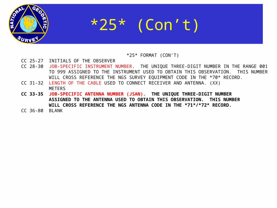
*25* (Con’t)
*25* FORMAT (CON’T)CC 25-27 INITIALS OF THE OBSERVERCC 28-30 JOB-SPECIFIC INSTRUMENT NUMBER. THE UNIQUE THREE-DIGIT NUMBER IN THE RANGE 001
TO 999 ASSIGNED TO THE INSTRUMENT USED TO OBTAIN THIS OBSERVATION. THIS NUMBER WILL CROSS REFERENCE THE NGS SURVEY EQUIPMENT CODE IN THE *70* RECORD.
CC 31-32 LENGTH OF THE CABLE USED TO CONNECT RECEIVER AND ANTENNA. (XX) METERS
CC 33-35 JOB-SPECIFIC ANTENNA NUMBER (JSAN). THE UNIQUE THREE-DIGIT NUMBERASSIGNED TO THE ANTENNA USED TO OBTAIN THIS OBSERVATION. THIS NUMBERWILL CROSS REFERENCE THE NGS ANTENNA CODE IN THE *71*/*72* RECORD.
CC 36-80 BLANK

*27* GPS OCCUPATION MEASUREMENT RECORD
*27* FORMAT
CC 01-06 SEQUENCE NUMBER. RIGHT JUSTIFIED. MUST BE AN INCREMENT OF 10 FROM PREVIOUS RECORD.
CC 07-10 DATA CODE. MUST BE *27*.CC 11-14 STATION SERIAL NUMBER (SSN). INSTRUMENT STATION. FOR ADDITIONAL INFORMATION
SEE CHAPTER 1, PAGES 1-2 THRU 1-6, JOB CODE AND SURVEY POINT NUMBERING; CHAPTER 2, PAGES 2-8 THRU 2-9, OBSERVATION DATA RECORDS; PAGES 2-12 THRU 2-13, ASSIGNMENT OF STATION SERIAL NUMBERS;
CC 15-20 DATE OF OBSERVATION.(UTC) YEAR, MONTH, DAY (YYMMDD). SEE CHAPTER 2, PAGES 2-18, DATE AND TIME.
CC 21-24 TIME. HOURS, MINUTES (HHMM)(UTC). SEE CHAPTER 2, PAGE 2-7, TIME, AND PAGE 2-18, DATE AND TIME.
CC 25-29 HEIGHT OF THE ANTENNA L1 PHASE CENTER ABOVE THE MONUMENT (XX.xxx) IN METERS.
*27* (Con’t)
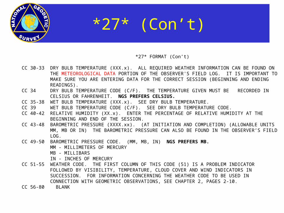
*27* FORMAT (Con’t)
CC 30-33 DRY BULB TEMPERATURE (XXX.x). ALL REQUIRED WEATHER INFORMATION CAN BE FOUND ON THE METEOROLOGICAL DATA PORTION OF THE OBSERVER'S FIELD LOG. IT IS IMPORTANT TO MAKE SURE YOU ARE ENTERING DATA FOR THE CORRECT SESSION (BEGINNING AND ENDING READINGS).
CC 34 DRY BULB TEMPERATURE CODE (C/F). THE TEMPERATURE GIVEN MUST BE RECORDED IN CELSIUS OR FAHRENHEIT. NGS PREFERS CELSIUS.
CC 35-38 WET BULB TEMPERATURE (XXX.x). SEE DRY BULB TEMPERATURE.CC 39 WET BULB TEMPERATURE CODE (C/F). SEE DRY BULB TEMPERATURE CODE.CC 40-42 RELATIVE HUMIDITY (XX.x). ENTER THE PERCENTAGE OF RELATIVE HUMIDITY AT THE
BEGINNING AND END OF THE SESSION.CC 43-48 BAROMETRIC PRESSURE (XXXX.xx). (AT INITIATION AND COMPLETION) (ALLOWABLE UNITS
MM, MB OR IN) THE BAROMETRIC PRESSURE CAN ALSO BE FOUND IN THE OBSERVER’S FIELD LOG.
CC 49-50 BAROMETRIC PRESSURE CODE. (MM, MB, IN) NGS PREFERS MB. MM - MILLIMETERS OF MERCURY MB - MILLIBARS IN - INCHES OF MERCURY
CC 51-55 WEATHER CODE. THE FIRST COLUMN OF THIS CODE (51) IS A PROBLEM INDICATOR FOLLOWED BY VISIBILITY, TEMPERATURE, CLOUD COVER AND WIND INDICATORS IN SUCCESSION. FOR INFORMATION CONCERNING THE WEATHER CODE TO BE USED IN CONNECTION WITH GEOMETRIC OBSERVATIONS, SEE CHAPTER 2, PAGES 2-10.
CC 56-80 BLANK

*70* INSTRUMENT RECORD
*70* FORMAT
CC 01-06 SEQUENCE NUMBER. RIGHT JUSTIFIED. MUST BE AN INCREMENT OF 10 FROM THE PREVIOUS RECORD.
CC 07-10 DATA CODE. MUST BE *70*.CC 11-13 JOB-SPECIFIC INSTRUMENT NUMBER (JSIN). MUST BE UNIQUE FOR EACH INSTRUMENT IN JOB.
SEE PAGES 2-10 AND 2-28.CC 14-16 NGS SURVEY EQUIPMENT CODE. SEE ANNEX F. USED TO IDENTIFY THE INSTRUMENT WHICH
WAS ASSIGNED THE JSIN IN CC 11-13 ABOVE.CC 17-20 RESOLUTION OF THE INSTRUMENT. RECORD THE SIZE OF THE SMALLEST DIRECTLY READABLE
MEASUREMENT UNIT OR THE RESOLUTION PUBLISHED BY THE INSTRUMENT MANUFACTURER, WHICHEVER IS LARGER (XXxx).
CC 21-22 UNITS. UNITS OF THE RESOLUTION USED IN CC 17-20 ABOVE. SEE PAGE 2-28, RESOLUTION OF THE INSTRUMENT AND UNITS.
CC 23-40 MANUFACTURER OF THE INSTRUMENT. SEE ANNEX F. (EXAMPLES: WILD, ZEISS/JENA, HEWLETT PACKARD).
CC 41-62 TYPE OF INSTRUMENT OR TRADE NAME. SEE ANNEX F. (EXAMPLES; DIRECTION THEODOLITE, CALIB INVAR TAPE, RANGE MASTER, TELLUROMETER).
CC 63-70 MODEL OR CLASS OF INSTRUMENT. SEE ANNEX F. (EXAMPLES: T-3, MA-100, 30-MT, 100-FT).
CC 71-80 SERIAL NUMBER. ALPHANUMERIC AND LEFT JUSTIFIED. LEAVE BLANK IF THE SERIAL NUMBER IS NOT KNOWN.
*72* GPS ANTENNA RECORD
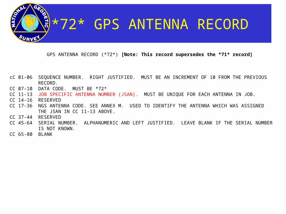
GPS ANTENNA RECORD (*72*) [Note: This record supersedes the *71* record]
cC 01-06 SEQUENCE NUMBER. RIGHT JUSTIFIED. MUST BE AN INCREMENT OF 10 FROM THE PREVIOUS RECORD.
CC 07-10 DATA CODE. MUST BE *72*CC 11-13 JOB SPECIFIC ANTENNA NUMBER (JSAN). MUST BE UNIQUE FOR EACH ANTENNA IN JOB. CC 14-16 RESERVEDCC 17-36 NGS ANTENNA CODE. SEE ANNEX M. USED TO IDENTIFY THE ANTENNA WHICH WAS ASSIGNED
THE JSAN IN CC 11-13 ABOVE. CC 37-44 RESERVEDCC 45-64 SERIAL NUMBER. ALPHANUMERIC AND LEFT JUSTIFIED. LEAVE BLANK IF THE SERIAL NUMBER
IS NOT KNOWN. CC 65-80 BLANK

*80* CONTROL POINT RECORD
*80* FORMAT
CC 01‑06 SEQUENCE NUMBER. RIGHT JUSTIFIED. INCREMENT BY 10 FROM THE PREVIOUS RECORD. CC 07‑10 DATA CODE. MUST BE *80*. CC 11‑14 STATION SERIAL NUMBER (SSN). SEE PAGES 1‑1, JOB CODE AND SURVEY POINT NUMBERING AND 2‑12, ASSIGNMENT OF STATION SERIAL NUMBERS. CC 15‑44 STATION NAME. MUST NOT EXCEED 30 CHARACTERS. THE NAME OF A HORIZONTAL CONTROL POINT WITH PERIPHERAL REFERENCE MARKS AND/OR AZIMUTH MARKS MUST NOT EXCEED 24 CHARACTERS TO ALLOW FOR ADDING RM 1, RM 2, AND/OR AZ MK TO THE NAME WITHOUT EXCEEDING THE 30
CHARACTER LENGTH LIMIT. CC 45‑55 LATITUDE. DEGREES, MINUTES, SECONDS (DDMMSSsssss). CC 56 DIRECTION OF LATITUDE. RECORD CODE "N" FOR NORTH OR CODE "S" FOR
SOUTH. CC 57‑68 LONGITUDE. DEGREES, MINUTES, SECONDS, (DDDMMSSsssss). CC 69 DIRECTION OF LONGITUDE. RECORD CODE "E" FOR EAST OR CODE "W" FOR
WEST.
NGS PREFERS THAT YOU USE THE NEW *86* RECORD FOR RECORDING THE ELEVATION (ORTHOMETRIC HEIGHT) AND ELEVATION CODE INSTEAD OF THE TWO DATA FIELDS THAT FOLLOW. REFER TO PAGES 2-83 THRU 2-85.

*80* CONTROL POINT RECORD
*80* FORMAT (Con’t)
CC 70‑75 ELEVATION. RECORD ELEVATION OF MARK ABOVE MEAN SEA LEVEL. IN METERS (MMMMmm). ENTER THE ELEVATION TO THE NEAREST CENTIMETER (cm). IF MEASUREMENT IS ONLY OBSERVED TO THE NEAREST DECIMETER (dm), LEAVE CC 75 BLANK, IF OBSERVED ONLY TO THE NEAREST METER (M), LEAVE CC 74-75 BLANK. THE APPROPRIATE ELEVATION CODE MUST
BE ENTERED IN CC 76. REFER TO PAGES 2‑34 and 2‑35, ELEVATION AND ELEVATION CODE.
CC 76 ELEVATION CODE. CC 77‑78 STATE OR COUNTRY CODE. IF THE CONTROL STATE IS LOCATED IN THE UNITED STATES/CANADA, ENTER THE CODE FROM ANNEX A FOR THE STATE/PROVINCE OR TERRITORY WHICH CONTAINS THE STATION. IF NOT, ENTER THE CODE FROM ANNEX A FOR THE COUNTRY WHICH CONTAINS THE STATION. SEE ANNEX A. CC 79‑80 STATION ORDER AND TYPE. REFER TO PAGES 2‑35 THRU 2‑38, STATION ORDER AND TYPE AND SEE ANNEX E.
*86* CONTROL POINT RECORD
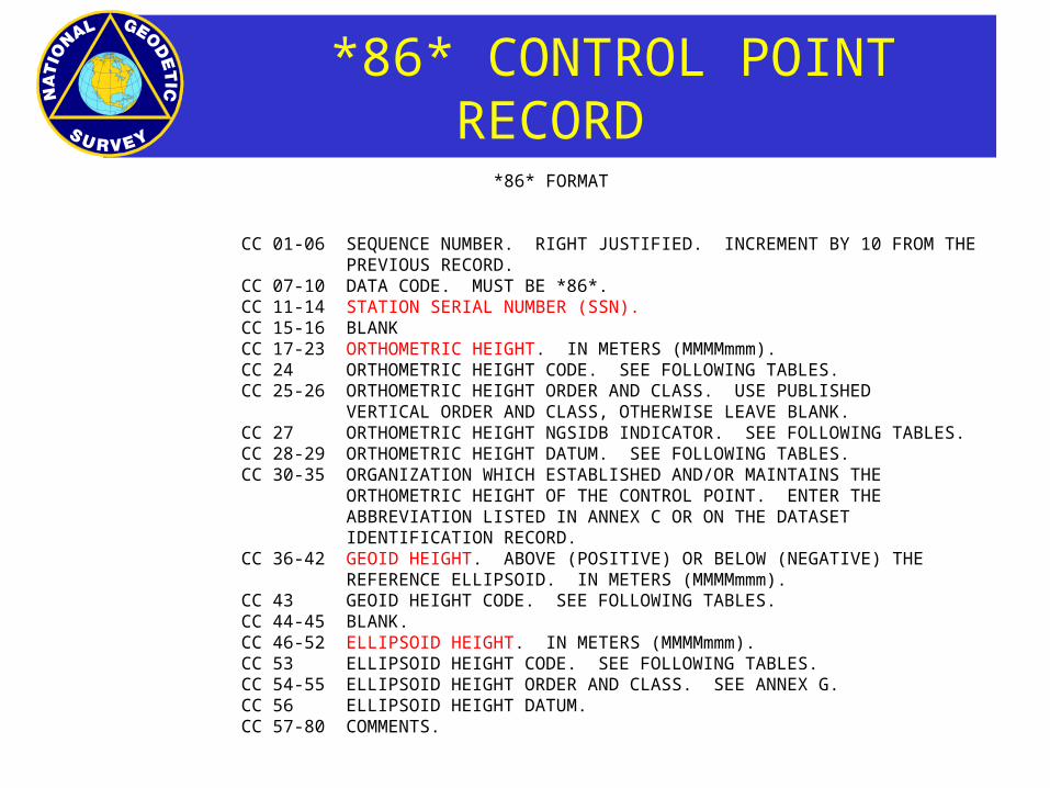
*86* FORMAT
CC 01-06 SEQUENCE NUMBER. RIGHT JUSTIFIED. INCREMENT BY 10 FROM THE PREVIOUS RECORD.
CC 07-10 DATA CODE. MUST BE *86*.CC 11-14 STATION SERIAL NUMBER (SSN).CC 15-16 BLANKCC 17-23 ORTHOMETRIC HEIGHT. IN METERS (MMMMmmm).CC 24 ORTHOMETRIC HEIGHT CODE. SEE FOLLOWING TABLES.CC 25-26 ORTHOMETRIC HEIGHT ORDER AND CLASS. USE PUBLISHED
VERTICAL ORDER AND CLASS, OTHERWISE LEAVE BLANK.CC 27 ORTHOMETRIC HEIGHT NGSIDB INDICATOR. SEE FOLLOWING TABLES.CC 28-29 ORTHOMETRIC HEIGHT DATUM. SEE FOLLOWING TABLES.CC 30-35 ORGANIZATION WHICH ESTABLISHED AND/OR MAINTAINS THE
ORTHOMETRIC HEIGHT OF THE CONTROL POINT. ENTER THE ABBREVIATION LISTED IN ANNEX C OR ON THE DATASET IDENTIFICATION RECORD.
CC 36-42 GEOID HEIGHT. ABOVE (POSITIVE) OR BELOW (NEGATIVE) THE REFERENCE ELLIPSOID. IN METERS (MMMMmmm).
CC 43 GEOID HEIGHT CODE. SEE FOLLOWING TABLES.CC 44-45 BLANK.CC 46-52 ELLIPSOID HEIGHT. IN METERS (MMMMmmm).
CC 53 ELLIPSOID HEIGHT CODE. SEE FOLLOWING TABLES. CC 54-55 ELLIPSOID HEIGHT ORDER AND CLASS. SEE ANNEX G. CC 56 ELLIPSOID HEIGHT DATUM. CC 57-80 COMMENTS.

CR8BB Program
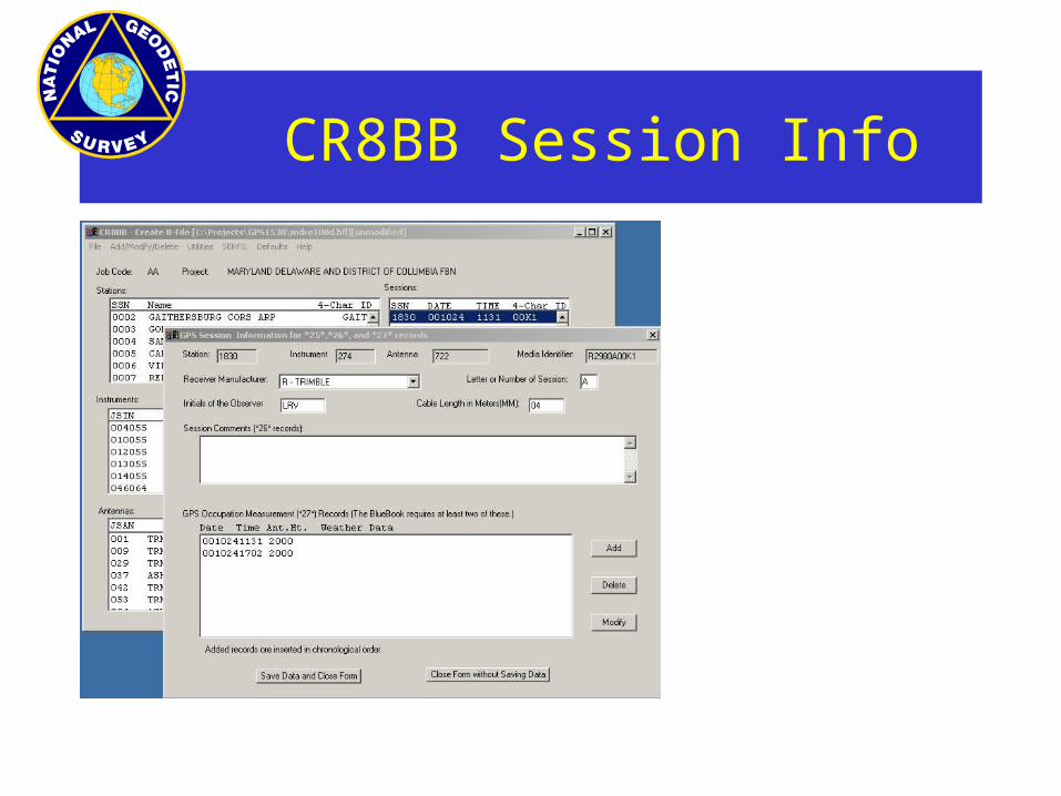
CR8BB Session Info

B-File Session Info
INPUT FILES - GFILE
•A - Project Record
•B - Session Header Record
•C - Vector Record
•D - Correlation Record

Sample GFILE

GFILE - PROJECT RECORD
Project Record
01‑01 A 02‑03 Job Code (Chapter 1) Alpha04‑07 Year, Start of Project (local) (CCYY) Integer08‑09 Month, Start of Project (local) (MM) Integer10‑11 Day, Start of Project (local) (DD) Integer12‑15 Year, End of Project (local) (CCYY) Integer16‑17 Month, End of Project (local) (MM) Integer18‑19 Day, End of Project (local) (DD) Integer20‑78 Title of project Alpha79-80 Reserved
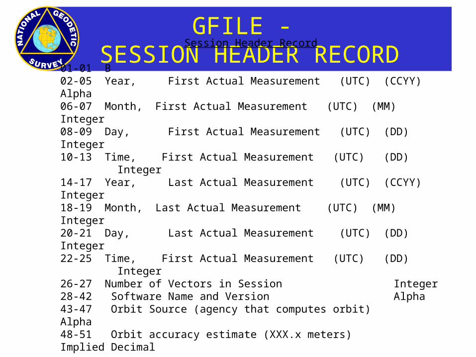
GFILE - SESSION HEADER RECORD
Session Header Record
01-01 B02-05 Year, First Actual Measurement (UTC) (CCYY) Alpha06-07 Month, First Actual Measurement (UTC) (MM) Integer08-09 Day, First Actual Measurement (UTC) (DD) Integer10-13 Time, First Actual Measurement (UTC) (DD) Integer14-17 Year, Last Actual Measurement (UTC) (CCYY) Integer18-19 Month, Last Actual Measurement (UTC) (MM) Integer20-21 Day, Last Actual Measurement (UTC) (DD) Integer22-25 Time, First Actual Measurement (UTC) (DD) Integer26-27 Number of Vectors in Session Integer28-42 Software Name and Version Alpha43-47 Orbit Source (agency that computes orbit) Alpha48-51 Orbit accuracy estimate (XXX.x meters) Implied Decimal

GFILE - SESSION HEADER RECORD
Session Header Record (con’t)
52-53 Solution Coordinate System code (table, N-6) Integer 54-55 Solution meteorological use code (table, N-6) Integer56-57 Solution ionosphere use code (table, N-6) Integer 58-59 Solution time parameter use code (table, N-6) Integer60-60 Nominal accuracy code (table, N-6) Integer61-66 Processing agency code (Annex C) Alpha67-70 Year of processing (CCYY) Integer71-72 Month of processing (MM) Integer73-74 Day of processing (DD) Integer75-80 Solution type (table, N-7) Integer
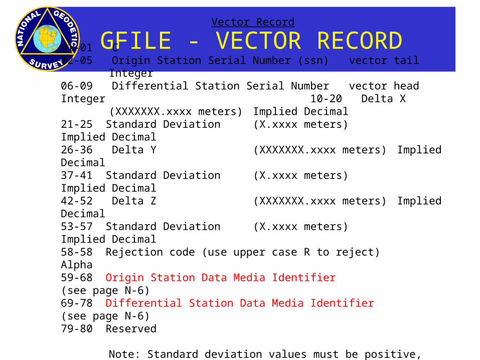
GFILE - VECTOR RECORD
Vector Record
01-01 C02-05 Origin Station Serial Number (ssn) vector tail Integer06-09 Differential Station Serial Number vector head Integer 10-20 Delta X (XXXXXXX.xxxx meters) Implied Decimal21-25 Standard Deviation (X.xxxx meters) Implied Decimal26-36 Delta Y (XXXXXXX.xxxx meters) Implied Decimal37-41 Standard Deviation (X.xxxx meters) Implied Decimal42-52 Delta Z (XXXXXXX.xxxx meters) Implied Decimal53-57 Standard Deviation (X.xxxx meters) Implied Decimal58-58 Rejection code (use upper case R to reject) Alpha59-68 Origin Station Data Media Identifier (see page N-6)69-78 Differential Station Data Media Identifier (see page N-6)79-80 Reserved
Note: Standard deviation values must be positive, non-zero numbers

GFILE - CORRELATION RECORD
Correlation Record
01-01 D02-04 Row Index Number Integer05-07 Column Index Number Integer 08-16 Correlation (XX.xxxxxxx meters) Implied Decimal17-19 Row Index Number Integer20-22 Column Index Number Integer 23-31 Correlation (XX.xxxxxxx meters) Implied Decimal32-34 Row Index Number Integer35-37 Column Index Number Integer 38-46 Correlation (XX.xxxxxxx meters) Implied Decimal47-49 Row Index Number Integer50-52 Column Index Number Integer 53-61 Correlation (XX.xxxxxxx meters) Implied Decimal62-64 Row Index Number Integer65-67 Column Index Number Integer 68-76 Correlation (XX.xxxxxxx meters) Implied Decimal79-80 Reserved

INPUT FILES - ADJUSTMENT FILE
•CC - Constrained Coordinate Record
•DD - Dimensionality Record
•II - Iteration Record
•MM - Adjustment Mode Record
•PP - Print Output Record
•QQ - Accuracy Computation Record
INPUT FILES - ADJUSTMENT FILE

AFILE - CC Record• CC ‑ Constrained Coordinate Record
• A Constrained Coordinate record specifies that a station is a control point, that its coordinate(s) are constrained or "held fixed" during the adjustment.
• This record follows the format of the Blue Book *80* record. • Columns Descriptions and Defaults Type• ‑‑‑‑‑‑‑‑‑‑‑‑‑‑‑‑‑‑‑‑‑‑‑‑‑‑‑‑‑‑‑‑‑‑‑‑‑‑‑‑‑‑‑‑‑‑‑‑‑‑‑‑‑‑‑‑‑‑‑‑• 01‑02 CC• 03‑10 Reserved• 11‑14 Station Serial Number (integer)• 15‑20 Latitude Standard Deviation (integer)• 21‑26 Longitude Standard Deviation (integer)• 27‑32 Height Standard Deviation (integer)• 33‑44 Reserved• 45‑46 Degrees Latitude (integer)• 47‑48 Minutes Latitude (integer)• 49‑55 Seconds Latitude (integer)• 56‑56 Latitude Code (N ‑‑ POSITIVE NORTH)• 57‑59 Degrees Longitude (integer)• 60‑61 Minutes Longitude (integer)• 62‑69 Seconds Longitude (integer)• 56‑56 Longitude Code (W ‑‑ POSITIVE WEST)• 70‑76 Height, units of millimeters (integer)• 77‑80 Reserved

AFILE - DD Record
• DD ‑ Dimensionality Record
• The Dimensionality record controls the number of spatial dimensions in which the program adjusts. ADJUST may adjust in 1, 2, 2.5, or 3 dimensions.
• Columns Descriptions and Defaults Type• ‑‑‑‑‑‑‑‑‑‑‑‑‑‑‑‑‑‑‑‑‑‑‑‑‑‑‑‑‑‑‑‑‑‑‑‑‑‑‑‑‑‑‑‑‑‑‑‑‑‑‑‑‑‑‑‑‑‑‑‑• 01‑02 DD• 03‑03 Dimensions of adjustment, no default (integer)• “3” for a 3 dimensional adjustment• 04‑05 ".5" for a 2.5 dimensional adjustment• 06‑80 Reserved
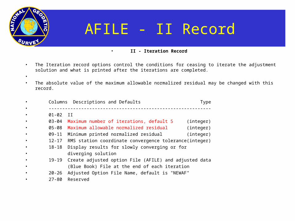
AFILE - II Record• II ‑ Iteration Record
• The Iteration record options control the conditions for ceasing to iterate the adjustment solution and what is printed after the iterations are completed.
• • The absolute value of the maximum allowable normalized residual may be changed with this
record.
• Columns Descriptions and Defaults Type• ‑‑‑‑‑‑‑‑‑‑‑‑‑‑‑‑‑‑‑‑‑‑‑‑‑‑‑‑‑‑‑‑‑‑‑‑‑‑‑‑‑‑‑‑‑‑‑‑‑‑‑‑‑‑‑‑‑‑‑‑• 01‑02 II• 03‑04 Maximum number of iterations, default 5 (integer)• 05‑08 Maximum allowable normalized residual (integer)• 09‑11 Minimum printed normalized residual (integer)• 12‑17 RMS station coordinate convergence tolerance(integer)• 18‑18 Display results for slowly converging or for• diverging solution• 19‑19 Create adjusted option File (AFILE) and adjusted data• (Blue Book) File at the end of each iteration• 20‑26 Adjusted Option File Name, default is "NEWAF"• 27‑80 Reserved

AFILE - MM Record
• MM ‑ Adjustment Mode Record
• The Adjustment Mode record controls the mode of adjustment, that is, to not iterate (Mode 0), or what should be done after
• The next two options on this record control whether or not a new Blue Book file should be created containing the adjusted positions. If it is to be created, a name for the file can be specified.
• Mode 0 ‑ This is a simulation mode. There are no iterations. This mode is normally used for network design with simulated data.
• Mode 1 ‑ The standard deviations of the residuals are assumed to be the same as the standard deviations of the observations. Also, the standard deviations of the parameters and station locations are not calculated.
• Mode 2 ‑ Same as Mode 1 except standard deviations of parameters and station locations are calculated.
• Mode 3 ‑ Same as Mode 2 except standard deviations of residuals are calculated.

AFILE - MM Record
• MM ‑ Adjustment Mode Record
• Columns Descriptions and Defaults Type• ‑‑‑‑‑‑‑‑‑‑‑‑‑‑‑‑‑‑‑‑‑‑‑‑‑‑‑‑‑‑‑‑‑‑‑‑‑‑‑‑‑‑‑‑‑‑‑‑‑‑‑‑‑‑‑‑‑‑‑‑• 01‑02 MM• 03‑03 Mode indicator• 3 -- Compute normal residuals and inverse• 04‑04 Post‑adjustment indicator
• N (default) ‑‑ DO NOT SCALE STANDARD DEVIATIONS BY A‑POSTERIORI • STANDARD DEVIATION OF UNIT WEIGHT
• Y ‑‑ Scale standard deviations by a-posteriori • standard deviation of unit weight • 05‑05 Create Adjusted Data (Blue Book) File• Y ‑‑ Create adjusted data file• 06‑12 Adjusted Data File Name• 13‑13 Abort if solution is singular• 14‑14 Create Adjusted Position File• 15‑21 Adjusted Position File Name• 22‑80 Reserved

AFILE - PP Record• PP ‑ Print Output Record
• The Print Output record contains the options for controlling what is listed in the output and with what format.
• Columns Descriptions and Defaults Type• ‑‑‑‑‑‑‑‑‑‑‑‑‑‑‑‑‑‑‑‑‑‑‑‑‑‑‑‑‑‑‑‑‑‑‑‑‑‑‑‑‑‑‑‑‑‑‑‑‑‑‑‑‑‑‑‑‑‑‑‑• 01‑02 PP• 03‑03 Echo Blue Book File• 0 ‑‑ ECHO ALL BLUE BOOK RECORDS (default)• 1 ‑‑ Echo observations only• 2 ‑‑ Echo large misclosures only• 04‑04 Echo G‑Format File• 0 ‑‑ ECHO ALL G‑FORMAT RECORDS (default)• 1 ‑‑ Echo observations only• 2 ‑‑ Echo large misclosures only• 05‑05 Display Constraints• 06‑08 Residual Output Tolerance, units of 0.1 sigma• 09‑ Display Direction ... Angle... Zenith Distance ... Distance • ... GPS ... Constrained Residuals ... Residuals Grouped Around• Intersection Sta…. Position Shifts ... Position Googe Numbers…• Observational Summary... Adjusted Position …Doppler ...• -23 N‑E‑U GPS Residuals• 24‑80 Reserved

AFILE - QQ Record• QQ ‑ Accuracy Computation Record
• Accuracy Computation record directs that the adjusted value of the distance, azimuth, and vertical angle between two stations be calculated together with associated statistics indicating the accuracy of these adjusted quantities.
• Columns Descriptions and Defaults Type• ‑‑‑‑‑‑‑‑‑‑‑‑‑‑‑‑‑‑‑‑‑‑‑‑‑‑‑‑‑‑‑‑‑‑‑‑‑‑‑‑‑‑‑‑‑‑‑‑‑‑‑‑‑‑‑‑‑‑‑‑• 01‑02 QQ• 03‑04 Classical and GPS survey order type (character)• 1, 21, 22, 3 for classical surveys• AA, A, B for a GPS survey• 04‑10 Reserved• 11‑14 Station Serial Number, required (integer)• 15‑50 Reserved• 51‑54 Station Serial Number, required (integer)• 55‑80 Reserved
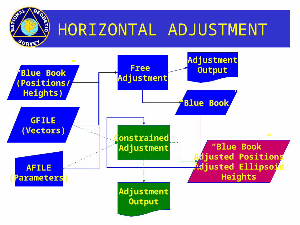
HORIZONTAL ADJUSTMENT
“Blue Book”(Positions/Heights)
GFILE(Vectors)
AFILE(Parameters)
Free Adjustment
Constrained Adjustment “Blue Book”
Adjusted PositionsAdjusted Ellipsoid
Heights
AdjustmentOutput
AdjustmentOutput
“Blue Book”

VERTICAL ADJUSTMENT
“Blue Book”(Positions/Heights)
GFILE(Vectors)
AFILE(Parameters)
VerticalFree
Adjustment
VerticalConstrained Adjustment
“Blue Book”Adjusted Orthometric
HeightsGeoid Heights
AdjustmentOutput
AdjustmentOutput
“Blue Book”

ADJUSTMENT OUTPUT 1of3

ADJUSTMENT OUTPUT 2 of 3
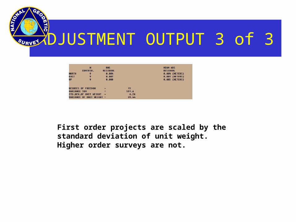
ADJUSTMENT OUTPUT 3 of 3
First order projects are scaled by the standard deviation of unit weight. Higher order surveys are not.

GUIDELINES
• Gather Source Material Digitized Files Sketches Field Reports/Logs
• Keep Good Records for Final Report
• Identify Control - Horizontal and Vertical
• Verify Reference Systems System used for Reduction = System Used in
Adjustment
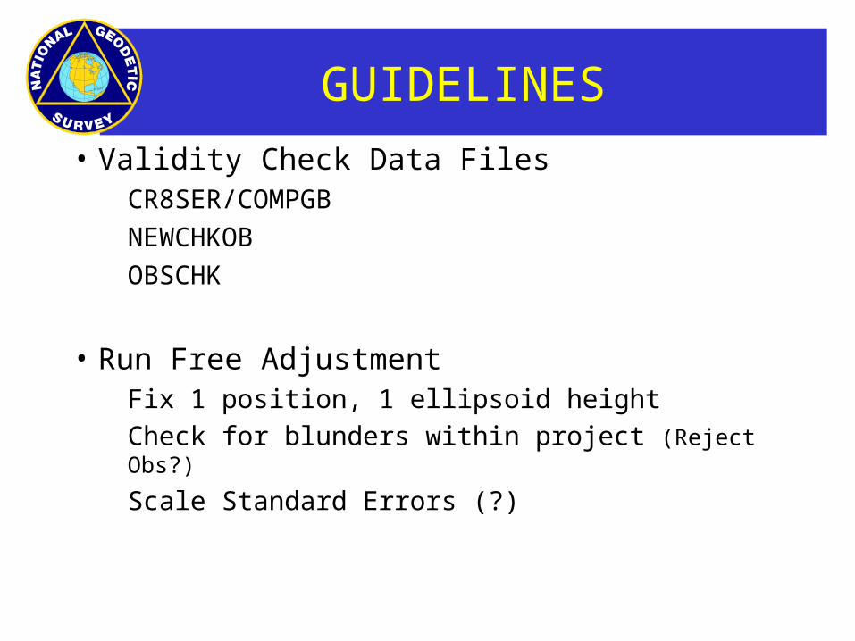
GUIDELINES
• Validity Check Data Files CR8SER/COMPGB
NEWCHKOB
OBSCHK
• Run Free Adjustment Fix 1 position, 1 ellipsoid height Check for blunders within project (Reject Obs?)
Scale Standard Errors (?)

GUIDELINES
• Run Horizontal Constrained Adjustment Fix all published positions and ellipsoid heights Evaluate residuals for consistency with control (Readjust Positions, Ellipsoid Heights?)
• Run Vertical Free Adjustment Add Geoid Heights Fix 1 position, one published orthometric height,
confirm statistics match horizontal free

GUIDELINES
• Run Vertical Constrained Adjustment Add Geoid Heights Fix 1 position, all published orthometric heights Evaluate residuals for consistency with control (Readjust
Orthometric Heights?)
• Run Free Adjustment to compute accuracies Fix 1 position and 1 ellipsoid height Determine if accuracies meet requirements (Readjust
Positions?)

GUIDELINES
• Post processing Compute ellipsoid height accuracies Create final complete blue book file Rerun checking programs Write report
• Appendices Processing Programs Processing and Report Checklists

SUBMIT FROM OBSERVING SESSIONS:
•From each Station:- “To reach” description/recovery, corrections noted- Visibility Obstruction Diagram, corrections noted
•From each Observation Session:- Raw GPS Data on 3.5” diskette- RINEX2 Data (Obs and Nav files) on 3.5” diskette- Observation Log- Pencil Rubbing Form
Note: keep for 5 years as backup - 3.5” diskettes of raw data, photocopy of Observation Logs

SUBMIT FROM ADJUSTMENT PROCESSING:
The following may be ASCII files or paper listings unless otherwise noted. Keep backups until notified that the database has been loaded.
•Free Adjustment•Constrained Horizontal Adjustment•Constrained Vertical Adjustment (NAVD88)•Free Adjustment with Accuracies•Final combined Blue Book file (ASCII)•Final Gfile (ASCII)

SUBMIT FROM ADJUSTMENT PROCESSING:
•Accuracy Listing - BBACCUR Output (paper)•ELLACC Output•COMPGB* Output•OBSCHK* Output
•Copies of Data Used to Identify (Horizontal and Vertical) Fixed Control
*Error or Warning Messages Must Be Explained

SUBMIT FROM ADJUSTMENT PROCESSING:
•CHKDESC* Output•OBSDES* Output
•Final Description File (ASCII)
*Error or Warning Messages Must Be Explained

PROJECT SUBMISSIONCHECKLIST
PROJECT SUBMISSION CHECKLISTGPS PROJECTS
Project Title: _____________________________________________
Accession Number: _____________________________________________
Submitting Agency: _____________________________________________
Observing Agency: _____________________________________________
Receiver Type: _____________________________________________
PACKAGE CONTENTS
Project Report and Attachments Required For
( ) Project Report All Projects( ) Approved Reconnaissance Project Sketch All Projects( ) Project Instructions or Contract Specifications All Projects( ) Final Station List All Projects( ) Station Visibility Diagrams All Projects( ) Final Observing Schedule All Projects( ) Observation Logs All Projects( ) Equipment Failure Logs NGS Projects( ) Loop Misclosures Optional
PROJECT SUBMISSIONCHECKLIST
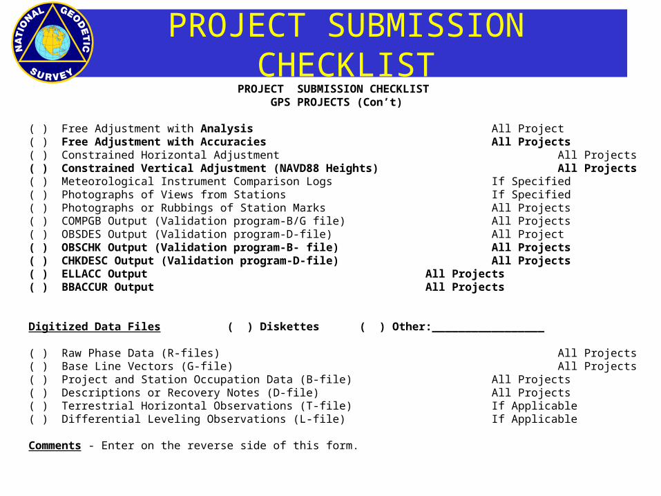
PROJECT SUBMISSION CHECKLISTGPS PROJECTS (Con’t)
( ) Free Adjustment with Analysis All Project( ) Free Adjustment with Accuracies All Projects( ) Constrained Horizontal Adjustment All Projects( ) Constrained Vertical Adjustment (NAVD88 Heights) All Projects( ) Meteorological Instrument Comparison Logs If Specified( ) Photographs of Views from Stations If Specified( ) Photographs or Rubbings of Station Marks All Projects( ) COMPGB Output (Validation program-B/G file) All Projects( ) OBSDES Output (Validation program-D-file) All Project( ) OBSCHK Output (Validation program-B- file) All Projects( ) CHKDESC Output (Validation program-D-file) All Projects( ) ELLACC Output All Projects( ) BBACCUR Output All Projects
Digitized Data Files ( ) Diskettes ( ) Other:_________________
( ) Raw Phase Data (R-files) All Projects( ) Base Line Vectors (G-file) All Projects( ) Project and Station Occupation Data (B-file) All Projects( ) Descriptions or Recovery Notes (D-file) All Projects( ) Terrestrial Horizontal Observations (T-file) If Applicable( ) Differential Leveling Observations (L-file) If Applicable
Comments - Enter on the reverse side of this form.

NEW STANDARDS FOR GEODETIC CONTROL
Two accuracy standards (http://fgdc.er.usgs.gov/standards/status/swgstat.html)
local accuracy ------------- adjacent points
network accuracy ---------- relative to CORS
Numeric quantities, units in cm (or mm)
Both are relative accuracy measures
Do not use distance dependent expression
Horizontal accuracies are radius of 2-D 95% error circle
Ellipsoidal/Orthometric heights are 1-D (linear) 95% error

NATIONAL GEODETIC SURVEY USEFUL WEB SITES
• NGS PC Software:– ADJUST, ADJUST Utilities, COMPGB, CR8BB, DDPROC,
GEOID96, HTDP, NADCON, VERTCON, and others• http://www.ngs.noaa.gov/PC_PROD/pc_prod.shtml
• NGS Tool Kit:– On-line Applications (includes OPUS)
• http://www.ngs.noaa.gov/TOOLS/
• Publications of the National Geodetic Survey:– Catalog
• http://www.ngs.noaa.gov/PC_PROD/pc_prod.shtml
– On-line• http://www.ngs.noaa.gov/PC_PROD/pc_prod.shtml
– On-line includes Guidelines for Establishing GPS-Derived Ellipsoid Heights (Standards: 2 CM and 5 CM),Version 4.3
• http://www.ngs.noaa.gov/PC_PROD/pc_prod.shtml

NATIONAL GEODETIC SURVEY USEFUL WEB SITES
• Input Formats and Specifications of the National Geodetic Survey Data Base (Blue Book):– http://www.ngs.noaa.gov/FGCS/BlueBook/
• Policy Statement for Incorporation of Geodetic Data into the National Geodetic Survey Data Base:– http://www.ngs.noaa.gov/INFO/incorp_data.html
• Geospatial Positioning Accuracy Standards– http://www.fgdc.gov/standards/status/textstatus.html
• Frequently asked questions:– http://www.ngs.noaa.gov/faq.shtml

ASK A GEODESIST
Do you have a scientific question?
Ask one of the NGS scientists!
If your question is about… Then ask...
The geoid [email protected]
Crustal motion [email protected]
Vertical Datum [email protected]
Horizontal Datum [email protected]
Heights, in general [email protected]
GeodeticAdvisors [email protected]
See the NGS Personnel Directory for current phone numbers.