submittal package cast iron service weight system · 5” 5.94 5.30 3.00 4.94 0.18 0.15 ......
TRANSCRIPT
1
SUBMITTAL PACKAGE
Submittal Package Cast Iron Service Weight System
(Updated July 18, 2018)
© 2018 Charlotte Pipe and Foundry Company
SUB-PAC-CI-SV
2
Cast Iron Service Submittal Package
Page
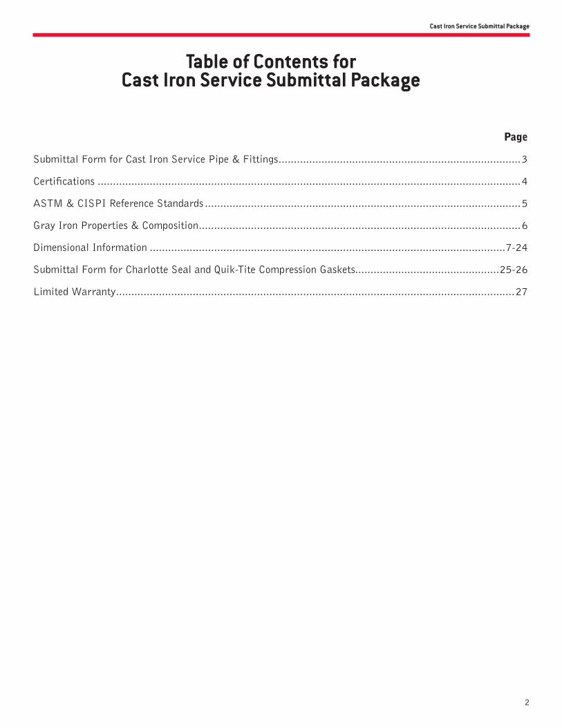
Submittal Form for Cast Iron Service Pipe & Fittings ...............................................................................3
Certifications ..........................................................................................................................................4
ASTM & CISPI Reference Standards .......................................................................................................5
Gray Iron Properties & Composition .........................................................................................................6
Dimensional Information ....................................................................................................................7-24
Submittal Form for Charlotte Seal and Quik-Tite Compression Gaskets ...............................................25-26
Limited Warranty ..................................................................................................................................27
Table of Contents forCast Iron Service Submittal Package
3FO-SUB-CI-SV (10-14-15)
Date: ________________Job Name: ______________________________ Location: _______________________________Engineer: _______________________________ Contractor: ______________________________
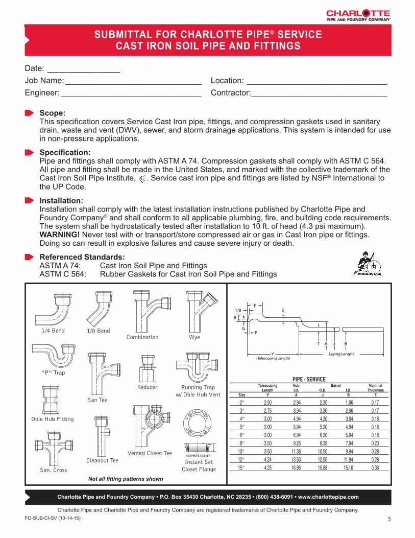
Scope: This specification covers Service Cast Iron pipe, fittings, and compression gaskets used in sanitary drain, waste and vent (DWV), sewer, and storm drainage applications. This system is intended for use in non-pressure applications.
Specification: Pipe and fittings shall comply with ASTM A 74. Compression gaskets shall comply with ASTM C 564. All pipe and fitting shall be made in the United States, and marked with the collective trademark of the Cast Iron Soil Pipe Institute, . Service cast iron pipe and fittings are listed by NSF® International to the UP Code.
Installation: Installation shall comply with the latest installation instructions published by Charlotte Pipe and Foundry Company® and shall conform to all applicable plumbing, fire, and building code requirements. The system shall be hydrostatically tested after installation to 10 ft. of head (4.3 psi maximum). WARNING! Never test with or transport/store compressed air or gas in Cast Iron pipe or fittings. Doing so can result in explosive failures and cause severe injury or death.
Referenced Standards: ASTM A 74: Cast Iron Soil Pipe and FittingsASTM C 564: Rubber Gaskets for Cast Iron Soil Pipe and Fittings
Not all fitting patterns shown
PIPE - SERVICE Telescoping Hub Barrel Nominal Length I.D. O.D. I.D. Thickness Size Y A J B T
2” 2.50 2.94 2.30 1.96 0.17 3” 2.75 3.94 3.30 2.96 0.17 4” 3.00 4.94 4.30 3.94 0.18 5” 3.00 5.94 5.30 4.94 0.18 6” 3.00 6.94 6.30 5.94 0.18 8” 3.50 9.25 8.38 7.94 0.23 10” 3.50 11.38 10.50 9.94 0.28 12” 4.24 13.50 12.50 11.94 0.28 15” 4.25 16.95 15.88 15.16 0.36
(Telescoping Length)Laying Length
BJAT
Y
PG
R
1/8 SF
Vented Closet TeeInstant Set
Closet FlangeCleanout Tee
Dble Hub Fitting
Running Trapw/ Dble Hub Vent
“P” Trap
Reducer
San Tee
Combination Wye1/8 Bend1/4 Bend
San. Cross
SUBMITTAL FOR CHARLOTTE PIPE® SERVICE CAST IRON SOIL PIPE AND FITTINGS
Charlotte Pipe and Charlotte Pipe and Foundry Company are registered trademarks of Charlotte Pipe and Foundry Company.
Charlotte Pipe and Foundry Company • P.O. Box 35430 Charlotte, NC 28235 • (800) 438-6091 • www.charlottepipe.com
4
Cast Iron Service Submittal Package
Very truly yours,
Hooper Hardison, President
Notary Public My commission expires July 02, 2022
TERRI L WILSON NOTARY PUBLIC
UNION COUNTY, NC My Commission Expires 7-2-2022
LC-Cl (7-18-18)
PO Box 35430 Charlotte, NC 28235 USA 704/372-5030 800/438-6091 FAX 800/553-1605
www.charlottepipe.com
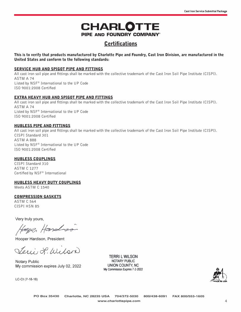
This is to verify that products manufactured by Charlotte Pipe and Foundry, Cast Iron Division, are manufactured in the United States and conform to the following standards:
SERVICE HUB AND SPIGOT PIPE AND FITTINGSAll cast iron soil pipe and fittings shall be marked with the collective trademark of the Cast Iron Soil Pipe Institute (CISPI).ASTM A 74Listed by NSF® International to the UP CodeISO 9001:2008 Certified
EXTRA HEAVY HUB AND SPIGOT PIPE AND FITTINGSAll cast iron soil pipe and fittings shall be marked with the collective trademark of the Cast Iron Soil Pipe Institute (CISPI).ASTM A 74Listed by NSF® International to the UP CodeISO 9001:2008 Certified
HUBLESS PIPE AND FITTINGSAll cast iron soil pipe and fittings shall be marked with the collective trademark of the Cast Iron Soil Pipe Institute (CISPI).CISPI Standard 301ASTM A 888Listed by NSF® International to the UP CodeISO 9001:2008 Certified
HUBLESS COUPLINGSCISPI Standard 310ASTM C 1277Certified by NSF® International
HUBLESS HEAVY DUTY COUPLINGSMeets ASTM C 1540
COMPRESSION GASKETSASTM C 564CISPI HSN 85
Certifications
Very truly yours,
Hooper Hardison, President
Notary Public My commission expires July 02, 2022
TERRI L WILSON NOTARY PUBLIC
UNION COUNTY, NC My Commission Expires 7-2-2022
LC-Cl (7-18-18)
PO Box 35430 Charlotte, NC 28235 USA 704/372-5030 800/438-6091 FAX 800/553-1605
www.charlottepipe.com
5
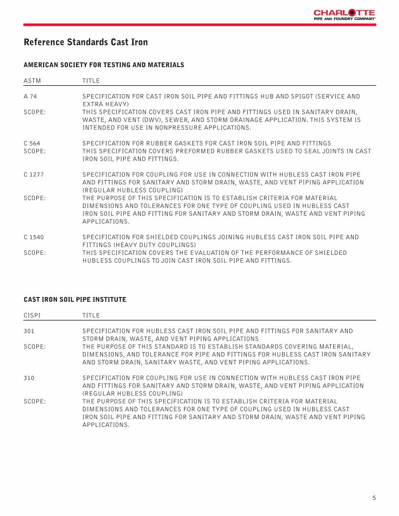
AMERICAN SOCIETY FOR TESTING AND MATERIALS
ASTM TITLE
A 74 SPECIFICATION FOR CAST IRON SOIL PIPE AND FITTINGS HUB AND SPIGOT (SERVICE AND EXTRA HEAVY)
SCOPE: THIS SPECIFICATION COVERS CAST IRON PIPE AND FITTINGS USED IN SANITARY DRAIN, WASTE, AND VENT (DWV), SEWER, AND STORM DRAINAGE APPLICATION. THIS SYSTEM IS INTENDED FOR USE IN NONPRESSURE APPLICATIONS.
C 564 SPECIFICATION FOR RUBBER GASKETS FOR CAST IRON SOIL PIPE AND FITTINGSSCOPE: THIS SPECIFICATION COVERS PREFORMED RUBBER GASKETS USED TO SEAL JOINTS IN CAST
IRON SOIL PIPE AND FITTINGS.
C 1277 SPECIFICATION FOR COUPLING FOR USE IN CONNECTION WITH HUBLESS CAST IRON PIPE AND FITTINGS FOR SANITARY AND STORM DRAIN, WASTE, AND VENT PIPING APPLICATION (REGULAR HUBLESS COUPLING)
SCOPE: THE PURPOSE OF THIS SPECIFICATION IS TO ESTABLISH CRITERIA FOR MATERIAL DIMENSIONS AND TOLERANCES FOR ONE TYPE OF COUPLING USED IN HUBLESS CAST IRON SOIL PIPE AND FITTING FOR SANITARY AND STORM DRAIN, WASTE AND VENT PIPING APPLICATIONS.
C 1540 SPECIFICATION FOR SHIELDED COUPLINGS JOINING HUBLESS CAST IRON SOIL PIPE AND FITTINGS (HEAVY DUTY COUPLINGS)
SCOPE: THIS SPECIFICATION COVERS THE EVALUATION OF THE PERFORMANCE OF SHIELDED HUBLESS COUPLINGS TO JOIN CAST IRON SOIL PIPE AND FITTINGS.
CAST IRON SOIL PIPE INSTITUTE
CISPI TITLE
301 SPECIFICATION FOR HUBLESS CAST IRON SOIL PIPE AND FITTINGS FOR SANITARY AND STORM DRAIN, WASTE, AND VENT PIPING APPLICATIONS
SCOPE: THE PURPOSE OF THIS STANDARD IS TO ESTABLISH STANDARDS COVERING MATERIAL, DIMENSIONS, AND TOLERANCE FOR PIPE AND FITTINGS FOR HUBLESS CAST IRON SANITARY AND STORM DRAIN, SANITARY WASTE, AND VENT PIPING APPLICATIONS.
310 SPECIFICATION FOR COUPLING FOR USE IN CONNECTION WITH HUBLESS CAST IRON PIPE AND FITTINGS FOR SANITARY AND STORM DRAIN, WASTE, AND VENT PIPING APPLICATION (REGULAR HUBLESS COUPLING)
SCOPE: THE PURPOSE OF THIS SPECIFICATION IS TO ESTABLISH CRITERIA FOR MATERIAL DIMENSIONS AND TOLERANCES FOR ONE TYPE OF COUPLING USED IN HUBLESS CAST IRON SOIL PIPE AND FITTING FOR SANITARY AND STORM DRAIN, WASTE AND VENT PIPING APPLICATIONS.
Reference Standards Cast Iron
6
Cast Iron Service Submittal Package
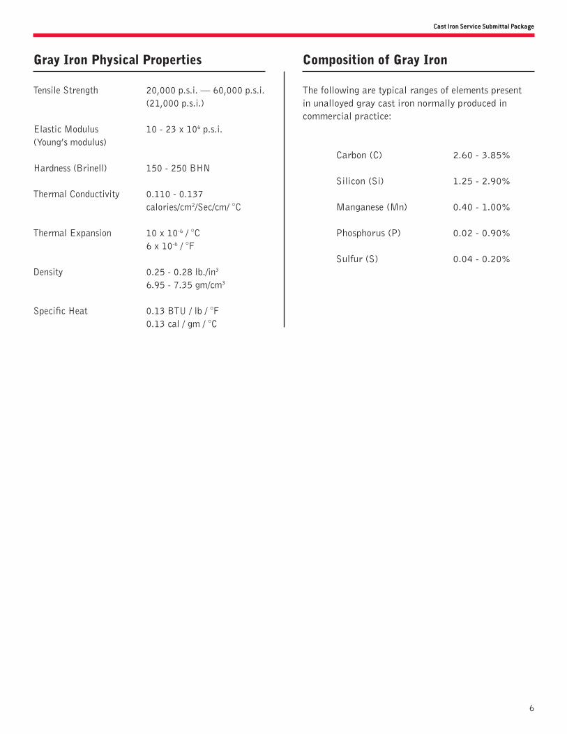
Gray Iron Physical Properties
Tensile Strength 20,000 p.s.i. — 60,000 p.s.i. (21,000 p.s.i.)
Elastic Modulus 10 - 23 x 106 p.s.i.(Young’s modulus)
Hardness (Brinell) 150 - 250 BHN
Thermal Conductivity 0.110 - 0.137 calories/cm2/Sec/cm/ °C
Thermal Expansion 10 x 10-6 / °C 6 x 10⁻⁶ / °F
Density 0.25 - 0.28 lb./in3
6.95 - 7.35 gm/cm3
Specific Heat 0.13 BTU / lb / °F 0.13 cal / gm / °C
Composition of Gray Iron
The following are typical ranges of elements present in unalloyed gray cast iron normally produced in commercial practice:
Carbon (C) 2.60 - 3.85%
Silicon (Si) 1.25 - 2.90%
Manganese (Mn) 0.40 - 1.00%
Phosphorus (P) 0.02 - 0.90%
Sulfur (S) 0.04 - 0.20%
7
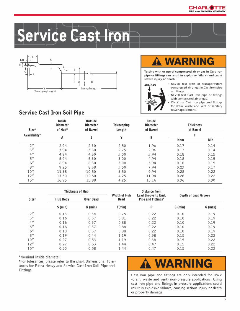
Service Cast Iron
Inside Outside Inside Diameter Diameter Telescoping Diameter Thickness SizeA of HubB of Barrel Length of Barrel of Barrel
AvailabilityB T
A J Y B Nom Min
Service Cast Iron Soil Pipe
2” 0.13 0.34 0.75 0.22 0.10 0.19 3” 0.16 0.37 0.81 0.22 0.10 0.19 4” 0.16 0.37 0.88 0.22 0.10 0.19 5” 0.16 0.37 0.88 0.22 0.10 0.19 6” 0.18 0.37 0.88 0.22 0.10 0.19 8” 0.19 0.44 1.19 0.38 0.15 0.22 10” 0.27 0.53 1.19 0.38 0.15 0.22 12” 0.27 0.53 1.44 0.47 0.15 0.22 15” 0.30 0.58 1.44 0.47 0.15 0.22
Thickness of Hub Distance from Width of Hub Lead Groove to End, Depth of Lead Groove SizeA Hub Body Over Bead Bead Pipe and FittingsB
S (min) R (min) F(min) P G (min) G (max)
2” 2.94 2.30 2.50 1.96 0.17 0.14 3” 3.94 3.30 2.75 2.96 0.17 0.14 4” 4.94 4.30 3.00 3.94 0.18 0.15 5” 5.94 5.30 3.00 4.94 0.18 0.15 6” 6.94 6.30 3.00 5.94 0.18 0.15 8” 9.25 8.38 3.50 7.94 0.23 0.17 10” 11.38 10.50 3.50 9.94 0.28 0.22 12” 13.50 12.50 4.25 11.94 0.28 0.22 15” 16.95 15.88 4.25 15.16 0.36 0.30
ANominal inside diameter.BFor tolerances, please refer to the chart Dimensional Toler-ances for Extra Heavy and Service Cast Iron Soli Pipe and Fittings.
• NEVER test with or transport/store compressed air or gas in Cast Iron pipe or fittings.
• NEVER test Cast Iron pipe or fittings with compressed air or gas.
• ONLY use Cast Iron pipe and fittings for drain, waste and vent or sanitary sewer applications.
Testing with or use of compressed air or gas in Cast Iron pipe or fittings can result in explosive failures and cause severe injury or death.
Cast Iron pipe and fittings are only intended for DWV (drain, waste and vent) non-pressure applications. Using cast iron pipe and fittings in pressure applications could result in explosive failures, causing serious injury or death or property damage.
(Telescoping Length)Laying Length
BJAT
Y
PG
R
1/8 SF
8
Cast Iron Service Submittal Package
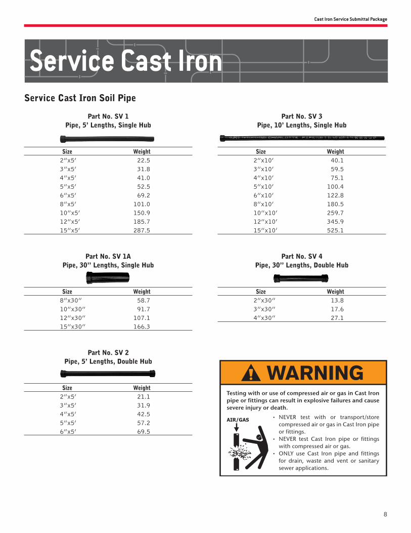
Service Cast Iron
Part No. SV 1Pipe, 5’ Lengths, Single Hub
Size Weight 2”x5’ 22.5 3”x5’ 31.8 4”x5’ 41.0 5”x5’ 52.5 6”x5’ 69.2 8”x5’ 101.0 10”x5’ 150.9 12”x5’ 185.7 15”x5’ 287.5
Part No. SV 1APipe, 30” Lengths, Single Hub
Size Weight 8”x30” 58.7 10”x30” 91.7 12”x30” 107.1 15”x30” 166.3
Part No. SV 2Pipe, 5’ Lengths, Double Hub
Size Weight 2”x5’ 21.1 3”x5’ 31.9 4”x5’ 42.5 5”x5’ 57.2 6”x5’ 69.5
Part No. SV 3Pipe, 10’ Lengths, Single Hub
Size Weight 2”x10’ 40.1 3”x10’ 59.5 4”x10’ 75.1 5”x10’ 100.4 6”x10’ 122.8 8”x10’ 180.5 10”x10’ 259.7 12”x10’ 345.9 15”x10’ 525.1
Part No. SV 4Pipe, 30” Lengths, Double Hub
Size Weight 2”x30” 13.8 3”x30” 17.6 4”x30” 27.1
• NEVER test with or transport/store compressed air or gas in Cast Iron pipe or fittings.
• NEVER test Cast Iron pipe or fittings with compressed air or gas.
• ONLY use Cast Iron pipe and fittings for drain, waste and vent or sanitary sewer applications.
Testing with or use of compressed air or gas in Cast Iron pipe or fittings can result in explosive failures and cause severe injury or death.
Service Cast Iron Soil Pipe
9
Service Pipe and Fittings
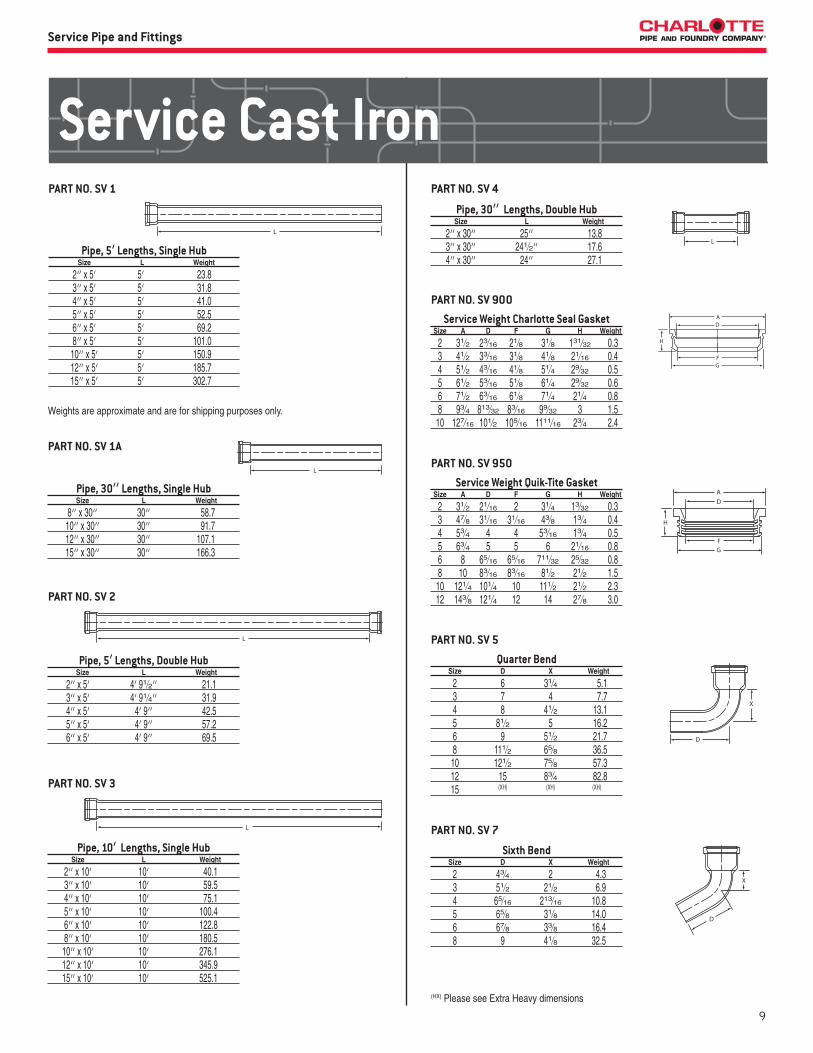
Pipe, 5’ Lengths, Single Hub Size L Weight
2” x 5’ 5’ 23.8 3” x 5’ 5’ 31.8 4” x 5’ 5’ 41.0 5” x 5’ 5’ 52.5 6” x 5’ 5’ 69.2 8” x 5’ 5’ 101.0 10” x 5’ 5’ 150.9 12” x 5’ 5’ 185.7 15” x 5’ 5’ 302.7
PART NO. SV 1
Weights are approximate and are for shipping purposes only.
Service Cast Iron
Pipe, 5’ Lengths, Double Hub Size L Weight
2” x 5’ 4’ 91⁄2” 21.1 3” x 5’ 4’ 91⁄4” 31.9 4” x 5’ 4’ 9” 42.5 5” x 5’ 4’ 9” 57.2 6” x 5’ 4’ 9” 69.5
Pipe, 10’ Lengths, Single Hub Size L Weight
2” x 10’ 10’ 40.1 3” x 10’ 10’ 59.5 4” x 10’ 10’ 75.1 5” x 10’ 10’ 100.4 6” x 10’ 10’ 122.8 8” x 10’ 10’ 180.5 10” x 10’ 10’ 276.1 12” x 10’ 10’ 345.9 15” x 10’ 10’ 525.1
PART NO. SV 3
PART NO. SV 2
Pipe, 30” Lengths, Single Hub Size L Weight
8” x 30” 30” 58.7 10” x 30” 30” 91.7 12” x 30” 30” 107.1 15” x 30” 30” 166.3
PART NO. SV 1A
Pipe, 30” Lengths, Double Hub Size L Weight
2” x 30” 25” 13.8 3” x 30” 241⁄2” 17.6 4” x 30” 24” 27.1
PART NO. SV 4
PART NO. SV 900
Service Weight Charlotte Seal Gasket Size A D F G H Weight
2 31⁄2 23⁄16 21⁄8 31⁄8 131⁄32 0.3 3 41⁄2 33⁄16 31⁄8 41⁄8 21⁄16 0.4 4 51⁄2 43⁄16 41⁄8 51⁄4 29⁄32 0.5 5 61⁄2 53⁄16 51⁄8 61⁄4 29⁄32 0.6 6 71⁄2 63⁄16 61⁄8 71⁄4 21⁄4 0.8 8 93⁄4 813⁄32 83⁄16 99⁄32 3 1.5 10 127⁄16 101⁄2 105⁄16 1111⁄16 23⁄4 2.4
PART NO. SV 950
Service Weight Quik-Tite Gasket Size A D F G H Weight
2 31⁄2 21⁄16 2 31⁄4 13⁄32 0.3 3 47⁄8 31⁄16 31⁄16 43⁄8 13⁄4 0.4 4 53⁄4 4 4 53⁄16 13⁄4 0.5 5 63⁄4 5 5 6 21⁄16 0.8 6 8 65⁄16 65⁄16 711⁄32 25⁄32 0.8 8 10 83⁄16 83⁄16 81⁄2 21⁄2 1.5 10 121⁄4 101⁄4 10 111⁄2 21⁄2 2.3 12 143⁄8 121⁄4 12 14 27⁄8 3.0
GF
DA
H
H
GF
A
D
Sixth Bend Size D X Weight
2 43⁄4 2 4.3 3 51⁄2 21⁄2 6.9 4 65⁄16 213⁄16 10.8 5 65⁄8 31⁄8 14.0 6 67⁄8 33⁄8 16.4 8 9 41⁄8 32.5
PART NO. SV 7
Quarter Bend Size D X Weight
2 6 31⁄4 5.1 3 7 4 7.7 4 8 41⁄2 13.1 5 81⁄2 5 16.2 6 9 51⁄2 21.7 8 111⁄2 65⁄8 36.5 10 121⁄2 75⁄8 57.3 12 15 83⁄4 82.8 15 (XH) (XH) (XH)
PART NO. SV 5
(HX) Please see Extra Heavy dimensions
10
Cast Iron Service Submittal PackageService Pipe and Fittings
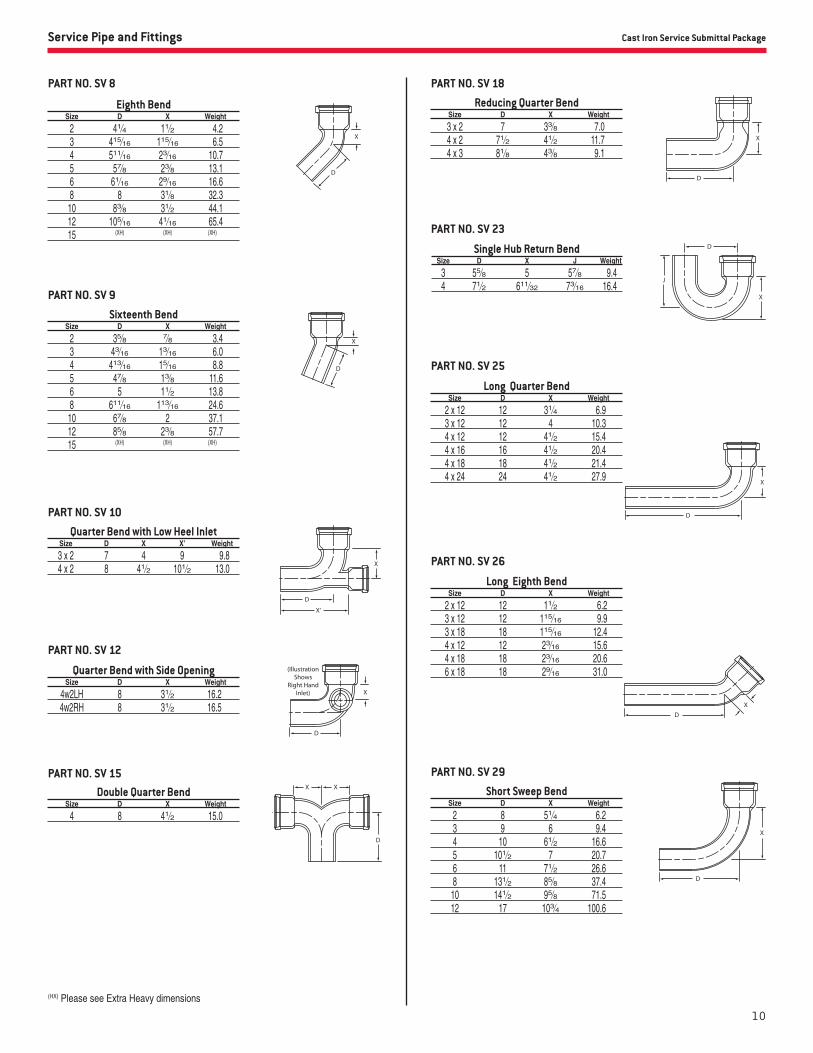
Eighth Bend Size D X Weight
2 41⁄4 11⁄2 4.2 3 415⁄16 115⁄16 6.5 4 511⁄16 23⁄16 10.7 5 57⁄8 23⁄8 13.1 6 61⁄16 29⁄16 16.6 8 8 31⁄8 32.3 10 83⁄8 31⁄2 44.1 12 105⁄16 41⁄16 65.4 15 (XH) (XH) (XH)
Sixteenth Bend Size D X Weight
2 35⁄8 7⁄8 3.4 3 43⁄16 13⁄16 6.0 4 413⁄16 15⁄16 8.8 5 47⁄8 13⁄8 11.6 6 5 11⁄2 13.8 8 611⁄16 113⁄16 24.6 10 67⁄8 2 37.1 12 85⁄8 23⁄8 57.7 15 (XH) (XH) (XH)
PART NO. SV 8
PART NO. SV 9
(HX) Please see Extra Heavy dimensions
Quarter Bend with Side Opening Size D X Weight
4w2LH 8 31⁄2 16.2 4w2RH 8 31⁄2 16.5
Double Quarter Bend Size D X Weight
4 8 41⁄2 15.0
PART NO. SV 12
PART NO. SV 15
Quarter Bend with Low Heel Inlet Size D X X’ Weight
3 x 2 7 4 9 9.8 4 x 2 8 41⁄2 101⁄2 13.0
PART NO. SV 10
Reducing Quarter Bend Size D X Weight
3 x 2 7 33⁄8 7.0 4 x 2 71⁄2 41⁄2 11.7 4 x 3 81⁄8 43⁄8 9.1
PART NO. SV 18
Long Quarter Bend Size D X Weight
2 x 12 12 31⁄4 6.9 3 x 12 12 4 10.3 4 x 12 12 41⁄2 15.4 4 x 16 16 41⁄2 20.4 4 x 18 18 41⁄2 21.4 4 x 24 24 41⁄2 27.9
PART NO. SV 25
Single Hub Return Bend Size D X J Weight
3 55⁄8 5 57⁄8 9.4 4 71⁄2 611⁄32 73⁄16 16.4
PART NO. SV 23
Long Eighth Bend Size D X Weight
2 x 12 12 11⁄2 6.2 3 x 12 12 115⁄16 9.9 3 x 18 18 115⁄16 12.4 4 x 12 12 23⁄16 15.6 4 x 18 18 23⁄16 20.6 6 x 18 18 29⁄16 31.0
PART NO. SV 26
Short Sweep Bend Size D X Weight
2 8 51⁄4 6.2 3 9 6 9.4 4 10 61⁄2 16.6 5 101⁄2 7 20.7 6 11 71⁄2 26.6 8 131⁄2 85⁄8 37.4 10 141⁄2 95⁄8 71.5 12 17 103⁄4 100.6
PART NO. SV 29
11
Service Pipe and Fittings
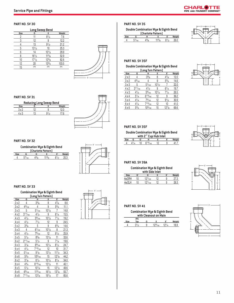
Long Sweep Bend Size D X Weight
2 11 81⁄4 7.6 3 12 9 12.2 4 13 91⁄2 21.2 5 131⁄2 10 25.3 6 14 101⁄2 29.9 8 161⁄2 115⁄8 52.9 10 171⁄2 125⁄8 82.6 12 20 133⁄4 103.5 15 (XH) (XH) (XH)
PART NO. SV 30
Reducing Long Sweep Bend Size D X Weight
3 x 2 12 9 12.0 4 x 3 13 91⁄2 17.6
PART NO. SV 31
Combination Wye & Eighth Bend (Charlotte Pattern)
Size G H X X’ Weight
4 57⁄16 43⁄8 113⁄8 61⁄2 20.3
PART NO. SV 32
Combination Wye & Eighth Bend (Long Turn Pattern)
Size G H X X’ Weight
2 x 2 4 33⁄8 8 47⁄8 8.6 3 x 2 43⁄16 4 9 53⁄4 11.1 3 x 3 5 51⁄16 101⁄2 7 14.8 4 x 2 311⁄16 41⁄2 9 61⁄4 15.5 4 x 3 41⁄2 59⁄16 101⁄2 71⁄2 19.2 4 x 4 41⁄2 71⁄2 12 9 24.5 5 x 2 33⁄8 5 9 63⁄4 14.6 5 x 3 4 61⁄16 101⁄2 8 21.3 5 x 4 41⁄4 75⁄16 12 91⁄2 25.9 5 x 5 51⁄2 85⁄8 131⁄2 11 33.6 6 x 2 211⁄16 51⁄2 9 71⁄4 19.6 6 x 3 31⁄8 69⁄16 101⁄4 81⁄2 24.7 6 x 4 41⁄4 713⁄16 12 10 31.7 6 x 5 51⁄16 91⁄8 131⁄2 111⁄2 34.3 6 x 6 53⁄4 105⁄16 15 127⁄8 44.2 8 x 2 31⁄8 61⁄2 101⁄2 81⁄4 34.0 8 x 4 43⁄4 813⁄16 131⁄2 11 40.1 8 x 5 51⁄2 101⁄8 15 121⁄2 49.6 8 x 6 65⁄16 115⁄16 161⁄2 137⁄8 55.7 8 x 8 711⁄16 137⁄8 191⁄2 17 85.6
PART NO. SV 33
Double Combination Wye & Eighth Bend (Charlotte Pattern)
Size G H X X’ Weight
4 57⁄16 43⁄8 113⁄8 61⁄2 26.0
PART NO. SV 35
Double Combination Wye & Eighth Bend (Long Turn Pattern)
Size G H X X’ Weight
2 x 2 4 33⁄8 8 47⁄8 12.0 3 x 2 43⁄16 4 9 53⁄4 14.6 3 x 3 5 51⁄16 101⁄2 7 22.0 4 x 2 311⁄16 41⁄2 9 61⁄4 19.7 4 x 3 41⁄2 59⁄16 101⁄2 71⁄2 26.5 4 x 4 51⁄4 613⁄16 12 9 36.2 5 x 4 41⁄4 75⁄16 12 91⁄2 30.9 6 x 4 41⁄4 713⁄16 12 10 41.0 6 x 6 53⁄4 105⁄16 15 127⁄8 69.6
PART NO. SV 35F
Combination Wye & Eighth Bend with Side Inlet
Size G’ H X X’ Weight
4w/2RH 10 121⁄16 12 9 27.3 4w/2LH 10 121⁄16 12 9 28.3
PART NO. SV 39A
Combination Wye & Eighth Bend with Cleanout on Main
IPS Size Tap G X X’ Weight
4 31⁄2 9 123⁄16 121⁄4 18.9
PART NO. SV 41
Double Combination Wye & Eighth Bend with 2” Cup Hub Inlet
Size G G’ H X X’ Weight
4 41⁄4 10 613⁄16 12 9 41.7
PART NO. SV 35F
12
Cast Iron Service Submittal PackageService Pipe and Fittings
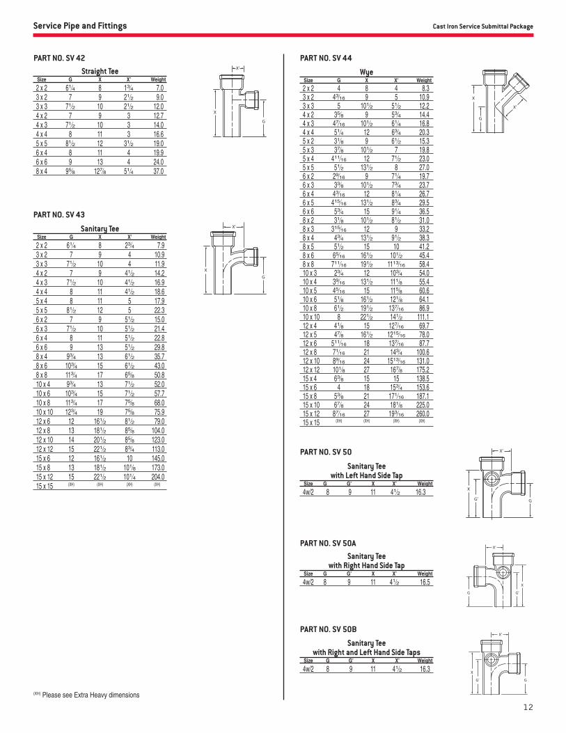
Sanitary Tee Size G X X’ Weight
2 x 2 61⁄4 8 23⁄4 7.9 3 x 2 7 9 4 10.9 3 x 3 71⁄2 10 4 11.9 4 x 2 7 9 41⁄2 14.2 4 x 3 71⁄2 10 41⁄2 16.9 4 x 4 8 11 41⁄2 18.6 5 x 4 8 11 5 17.9 5 x 5 81⁄2 12 5 22.3 6 x 2 7 9 51⁄2 15.0 6 x 3 71⁄2 10 51⁄2 21.4 6 x 4 8 11 51⁄2 22.8 6 x 6 9 13 51⁄2 29.8 8 x 4 93⁄4 13 61⁄2 35.7 8 x 6 103⁄4 15 61⁄2 43.0 8 x 8 113⁄4 17 65⁄8 50.8 10 x 4 93⁄4 13 71⁄2 52.0 10 x 6 103⁄4 15 71⁄2 57.7 10 x 8 113⁄4 17 75⁄8 68.0 10 x 10 123⁄4 19 75⁄8 75.9 12 x 6 12 161⁄2 81⁄2 79.0 12 x 8 13 181⁄2 85⁄8 104.0 12 x 10 14 201⁄2 85⁄8 123.0 12 x 12 15 221⁄2 83⁄4 113.0 15 x 6 12 161⁄2 10 145.0 15 x 8 13 181⁄2 101⁄8 173.0 15 x 12 15 221⁄2 101⁄4 204.0 15 x 15 (XH) (XH) (XH) (XH)
PART NO. SV 43
(XH) Please see Extra Heavy dimensions
Wye Size G X X’ Weight
2 x 2 4 8 4 8.3 3 x 2 43⁄16 9 5 10.9 3 x 3 5 101⁄2 51⁄2 12.2 4 x 2 35⁄8 9 53⁄4 14.4 4 x 3 47⁄16 101⁄2 61⁄4 16.8 4 x 4 51⁄4 12 63⁄4 20.3 5 x 2 31⁄8 9 61⁄2 15.3 5 x 3 37⁄8 101⁄2 7 19.8 5 x 4 411⁄16 12 71⁄2 23.0 5 x 5 51⁄2 131⁄2 8 27.0 6 x 2 29⁄16 9 71⁄4 19.7 6 x 3 33⁄8 101⁄2 73⁄4 23.7 6 x 4 43⁄16 12 81⁄4 26.7 6 x 5 415⁄16 131⁄2 83⁄4 29.5 6 x 6 53⁄4 15 91⁄4 36.5 8 x 2 31⁄8 101⁄2 81⁄2 31.0 8 x 3 315⁄16 12 9 33.2 8 x 4 43⁄4 131⁄2 91⁄2 38.3 8 x 5 51⁄2 15 10 41.2 8 x 6 65⁄16 161⁄2 101⁄2 45.4 8 x 8 711⁄16 191⁄2 1113⁄16 58.4 10 x 3 23⁄4 12 103⁄4 54.0 10 x 4 39⁄16 131⁄2 111⁄8 55.4 10 x 5 45⁄16 15 115⁄8 60.6 10 x 6 51⁄8 161⁄2 121⁄8 64.1 10 x 8 61⁄2 191⁄2 137⁄16 86.9 10 x 10 8 221⁄2 141⁄2 111.1 12 x 4 41⁄8 15 127⁄16 69.7 12 x 5 47⁄8 161⁄2 1215⁄16 78.0 12 x 6 511⁄16 18 137⁄16 87.7 12 x 8 71⁄16 21 143⁄4 100.6 12 x 10 89⁄16 24 1513⁄16 131.0 12 x 12 101⁄8 27 167⁄8 175.2 15 x 4 63⁄8 15 15 138.5 15 x 6 4 18 153⁄4 153.6 15 x 8 53⁄8 21 171⁄16 187.1 15 x 10 67⁄8 24 181⁄8 225.0 15 x 12 87⁄16 27 193⁄16 260.0 15 x 15 (XH) (XH) (XH) (XH)
PART NO. SV 44
Sanitary Tee with Left Hand Side Tap
Size G G’ X X’ Weight
4w/2 8 9 11 41⁄2 16.3
PART NO. SV 50
Sanitary Tee with Right Hand Side Tap
Size G G’ X X’ Weight
4w/2 8 9 11 41⁄2 16.5
Sanitary Tee with Right and Left Hand Side Taps
Size G G’ X X’ Weight
4w/2 8 9 11 41⁄2 16.3
PART NO. SV 50A
PART NO. SV 50B
Straight Tee Size G X X’ Weight
2 x 2 61⁄4 8 13⁄4 7.0 3 x 2 7 9 21⁄2 9.0 3 x 3 71⁄2 10 21⁄2 12.0 4 x 2 7 9 3 12.7 4 x 3 71⁄2 10 3 14.0 4 x 4 8 11 3 16.6 5 x 5 81⁄2 12 31⁄2 19.0 6 x 4 8 11 4 19.9 6 x 6 9 13 4 24.0 8 x 4 95⁄8 127⁄8 51⁄4 37.0
PART NO. SV 42
13
Service Pipe and Fittings
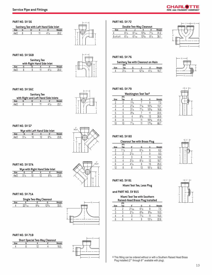
Sanitary Tee with Left Hand Side Inlet Size G G’ X X’ Weight
4w/2 8 9 11 41⁄2 20.2
PART NO. SV 56
Sanitary Tee with Right and Left Hand Side Inlets
Size G G’ X X’ Weight
4w/2 8 9 11 41⁄2 23.1
Sanitary Tee with Right Hand Side Inlet
Size G G’ X X’ Weight
4w/2 8 9 11 41⁄2 20.0
PART NO. SV 56B
PART NO. SV 56C
Wye with Left Hand Side Inlet Size G G’ X X’ Weight
4w/2 51⁄4 10 12 63⁄4 23.8
Wye with Right Hand Side Inlet Size G G’ X X’ Weight
4w/2 51⁄4 10 12 63⁄4 23.8
PART NO. SV 57
PART NO. SV 57A
Short Special Two-Way Cleanout Size G X X’ Weight
4 8 12 4 16.0
Single Two-Way Cleanout Size X E’ G Weight
4 227⁄16 93⁄8 123⁄4 33.5
Double Two-Way Cleanout Size G J X X’ Weight
4 61⁄2 67⁄16 135⁄8 71⁄2 31.2 6 x 4 x 4 61⁄2 67⁄16 135⁄8 81⁄4 39.1
PART NO. SV 71A
PART NO. SV 71B
PART NO. SV 72
Sanitary Tee with Cleanout on Main IPS Size Tap G X X’ Weight
4 31⁄2 8 121⁄8 41⁄2 16.7
PART NO. SV 76
Miami Test Tee, Less Plug
Cleanout Tee with Brass Plug IPS Size Tap E’ G X Weight
2 11⁄2 2 61⁄4 8 6.2 3 2 21⁄2 7 9 9.3 4 3 3 8 11 14.6 5 4 31⁄2 81⁄2 12 18.7 6 4 41⁄4 9 13 25.3 12 8 8 13 181⁄2 92.2
Washington Test Tee¥ IPS Size Tap E’ G X Weight
2 2 13⁄4 7 9 7.3 3 4 27⁄8 71⁄8 103⁄4 13.1 4 4 31⁄4 71⁄4 105⁄8 16.8 5 5 35⁄8 7 11 22.5 6 6 4 83⁄4 13 26.9 8 8 5 11 163⁄8 41.6 10 10 71⁄2 11 175⁄8 68.7
PART NO. SV 79
PART NO. SV 80
PART NO. SV 81
¥ This fitting can be ordered without or with a Southern Raised Head Brass Plug installed (2” through 8” available with plug).
Miami Test Tee with SouthernRaised-Head Brass Plug Installed
IPS Size Tap E’ G X Weight
2 2 21⁄32 61⁄2 9 7.0 3 3 21⁄2 65⁄8 95⁄8 10.0 4 4 3 71⁄4 11 15.5 6 6 4 9 131⁄4 22.8
and PART NO. SV 81S
14
Cast Iron Service Submittal PackageService Pipe and Fittings
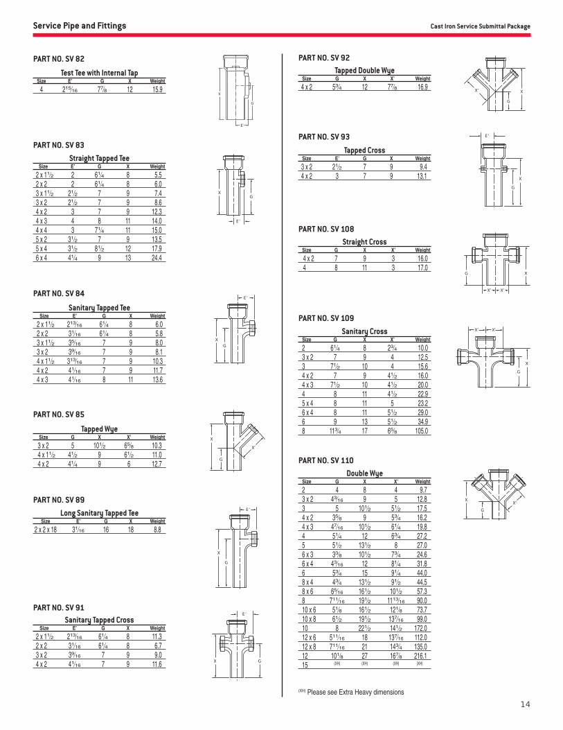
PART NO. SV 82
Test Tee with Internal Tap Size E’ G X Weight
4 215⁄16 77⁄8 12 15.9
Straight Tapped Tee Size E’ G X Weight
2 x 11⁄2 2 61⁄4 8 5.5 2 x 2 2 61⁄4 8 6.0 3 x 11⁄2 21⁄2 7 9 7.4 3 x 2 21⁄2 7 9 8.6 4 x 2 3 7 9 12.3 4 x 3 4 8 11 14.0 4 x 4 3 71⁄4 11 15.0 5 x 2 31⁄2 7 9 13.5 5 x 4 31⁄2 81⁄2 12 17.9 6 x 4 41⁄4 9 13 24.4
Sanitary Tapped Tee Size E’ G X Weight
2 x 11⁄2 213⁄16 61⁄4 8 6.0 2 x 2 31⁄16 61⁄4 8 5.8 3 x 11⁄2 35⁄16 7 9 8.0 3 x 2 39⁄16 7 9 8.1 4 x 11⁄2 313⁄16 7 9 10.3 4 x 2 41⁄16 7 9 11.7 4 x 3 41⁄16 8 11 13.6
PART NO. SV 83
PART NO. SV 84
Long Sanitary Tapped Tee Size E’ G X Weight
2 x 2 x 18 31⁄16 16 18 8.8
Tapped Wye Size G X X’ Weight
3 x 2 5 101⁄2 65⁄8 10.3 4 x 11⁄2 41⁄2 9 61⁄2 11.0 4 x 2 41⁄4 9 6 12.7
PART NO. SV 85
PART NO. SV 89
Sanitary Tapped Cross Size E’ G X Weight
2 x 11⁄2 213⁄16 61⁄4 8 11.3 2 x 2 31⁄16 61⁄4 8 6.7 3 x 2 39⁄16 7 9 9.0 4 x 2 41⁄16 7 9 11.6
Tapped Double Wye Size G X X’ Weight
4 x 2 53⁄4 12 77⁄8 16.9
PART NO. SV 91
PART NO. SV 92
Tapped Cross Size E’ G X Weight
3 x 2 21⁄2 7 9 9.4 4 x 2 3 7 9 13.1
PART NO. SV 93
Sanitary Cross Size G X X’ Weight
2 61⁄4 8 23⁄4 10.0 3 x 2 7 9 4 12.5 3 71⁄2 10 4 15.6 4 x 2 7 9 41⁄2 16.0 4 x 3 71⁄2 10 41⁄2 20.0 4 8 11 41⁄2 22.9 5 x 4 8 11 5 23.2 6 x 4 8 11 51⁄2 29.0 6 9 13 51⁄2 34.9 8 113⁄4 17 65⁄8 105.0
PART NO. SV 109
Straight Cross Size G X X’ Weight
4 x 2 7 9 3 16.0 4 8 11 3 17.0
PART NO. SV 108
Double Wye Size G X X’ Weight
2 4 8 4 9.7 3 x 2 43⁄16 9 5 12.8 3 5 101⁄2 51⁄2 17.5 4 x 2 35⁄8 9 53⁄4 16.2 4 x 3 47⁄16 101⁄2 61⁄4 19.8 4 51⁄4 12 63⁄4 27.2 5 51⁄2 131⁄2 8 27.0 6 x 3 33⁄8 101⁄2 73⁄4 24.6 6 x 4 43⁄16 12 81⁄4 31.8 6 53⁄4 15 91⁄4 44.0 8 x 4 43⁄4 131⁄2 91⁄2 44.5 8 x 6 65⁄16 161⁄2 101⁄2 57.3 8 711⁄16 191⁄2 1113⁄16 90.0 10 x 6 51⁄8 161⁄2 121⁄8 73.7 10 x 8 61⁄2 191⁄2 137⁄16 99.0 10 8 221⁄2 141⁄2 172.0 12 x 6 511⁄16 18 137⁄16 112.0 12 x 8 711⁄16 21 143⁄4 135.0 12 101⁄8 27 167⁄8 216.1 15 (XH) (XH) (XH) (XH)
PART NO. SV 110
(XH) Please see Extra Heavy dimensions
15
Service Pipe and Fittings
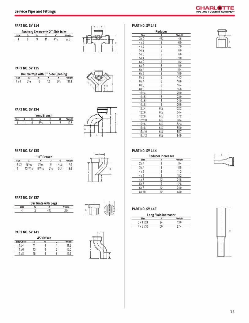
Sanitary Cross with 2” Side Inlet Size G G’ X X’ Weight
4 8 9 11 41⁄2 27.0
PART NO. SV 114
“H” Branch Size X X’ J G Weight
4 x 3 123⁄16 79⁄16 6 41⁄2 17.0 4 1315⁄16 811⁄16 61⁄2 51⁄4 19.6
Double Wye with 2” Side Opening Size G H X X’ Weight
4 x 4 51⁄4 10 12 63⁄4 31.8
PART NO. SV 115
PART NO. SV 135
Bar Grate with Legs Size G X Weight
4 3 43⁄4 2.0
45° Offset Size/Offset X G’ J Weight
4 x 4 11 4 4 11.6 4 x 6 13 4 6 15.0 4 x 8 15 4 8 15.6
PART NO. SV 137
PART NO. SV 141
Vent BranchSize X X’ J G G’ Weight
4 11 6 61⁄2 4 8 19.6
PART NO. SV 134
Reducer Size X Weight
3 x 2 43⁄4 4.6 4 x 2 5 6.0 4 x 3 5 7.0 5 x 2 5 6.6 5 x 3 5 6.8 5 x 4 5 9.0 6 x 2 5 8.2 6 x 3 5 9.9 6 x 4 5 10.4 6 x 5 5 10.9 8 x 3 6 14.3 8 x 4 6 16.6 8 x 5 6 16.4 8 x 6 6 16.8 10 x 4 6 20.0 10 x 5 6 23.9 10 x 6 6 24.0 10 x 8 6 26.5 12 x 4 61⁄2 32.2 12 x 6 61⁄2 34.4 12 x 8 61⁄2 37.2 12 x 10 61⁄2 38.4 15 x 6 61⁄2 52.3 15 x 8 61⁄2 55.0 15 x 10 61⁄2 55.7 15 x 12 61⁄2 64.9
PART NO. SV 143
Reducer Increaser Size X Weight
2 x 4 9 9.4 3 x 4 9 8.8 4 x 5 9 11.3 4 x 6 9 15.2 4 x 8 12 24.5 5 x 6 9 12.8 6 x 8 12 24.0 8 x 10 12 44.0
PART NO. SV 144
Long Plain Increaser Size X Weight
3 x 4 x 24 24 13.6 4 x 5 x 30 30 27.4
PART NO. SV 147
16
Cast Iron Service Submittal PackageService Pipe and Fittings
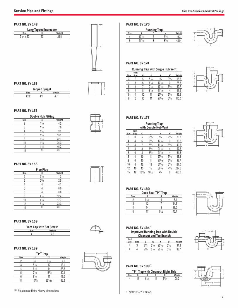
Long Tapped Increaser Size X Weight
2 x 4 x 30 30 22.8
PART NO. SV 148
Tapped Spigot Size A Weight
4 x 2 41⁄4 4.7
PART NO. SV 151
Vent Cap with Set Screw Size Weight
4 2.6
Pipe Plug Size X Weight
2 31⁄2 1.3 3 33⁄4 2.5 4 4 4.1 5 4 6.0 6 4 8.0 8 41⁄2 12.4 10 41⁄2 17.7 12 51⁄4 23.3 15 (XH) (XH)
Double Hub Fitting Size X Weight
2 11⁄4 4.2 3 11⁄4 7.0 4 11⁄2 9.1 6 11⁄2 13.1 8 11⁄2 22.1 10 11⁄2 36.3 12 11⁄2 46.3 15 (XH) (XH)
PART NO. SV 153
PART NO. SV 155
PART NO. SV 159
“P” Trap Size J X Weight
2 4 91⁄2 7.1 3 51⁄2 12 13.1 4 61⁄2 14 23.2 5 71⁄2 151⁄2 30.4 6 81⁄2 17 42.0 8 101⁄2 221⁄16 86.2
PART NO. SV 169
(XH) Please see Extra Heavy dimensions
Running Trap Size X C J Weight
4 171⁄2 6 61⁄2 19.3 6 211⁄2 8 81⁄2 48.0
Running Trap with Single Hub Vent Vent Size Size C J X X’ Weight
3 3 5 51⁄2 15 21⁄2 15.3 4 4 6 61⁄2 171⁄2 3 28.3 5 4 7 71⁄2 191⁄2 31⁄2 39.7 6 4 8 81⁄2 211⁄2 4 45.9 8 4 10 11 275⁄8 51⁄4 95.9 8 6 10 11 275⁄8 51⁄4 110.0
PART NO. SV 170
PART NO. SV 174
Running Trap with Double Hub Vent
Vent Size Size C J X X’ Weight
3 3 5 51⁄2 15 21⁄2 23.0 4 4 6 61⁄2 171⁄2 3 36.3 5 4 7 71⁄2 191⁄2 31⁄2 42.5 6 4 8 81⁄2 211⁄2 4 57.3 6 6 8 81⁄2 211⁄2 4 61.5 8 4 10 11 275⁄8 51⁄4 98.8 8 6 10 11 275⁄8 51⁄4 99.7 10 8 12 13 315⁄8 61⁄4 187.0 12 10 15 15 383⁄4 71⁄4 287.6 15 12 181⁄2 181⁄2 45 9 460.0
PART NO. SV 175
Deep Seal “P” Trap Size X J Weight
2 91⁄2 6 8.1 3 12 7 14.3 4 14 8 29.0 6 17 91⁄2 40.4
“P” Trap with Cleanout Right Side Size X J B D Weight
4 14 61⁄2 11 51⁄2 20.0
Improved Running Trap with Double Cleanout and Tee Branch
Vent Size Size E G X X’ Weight
4 3 51⁄4 61⁄4 201⁄2 51⁄2 34.3 4 4 53⁄8 61⁄4 201⁄2 51⁄2 33.7
PART NO. SV 180
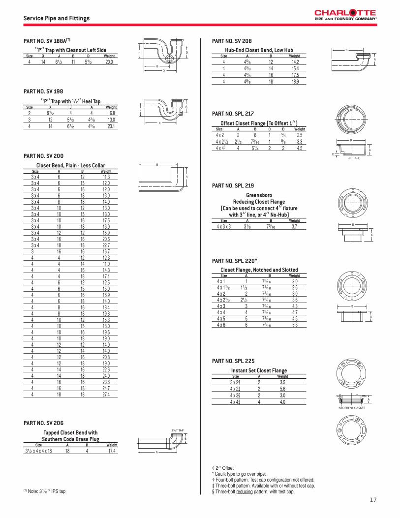
PART NO. SV 184(T)
PART NO. SV 188(T)
(T) Note: 31⁄2” IPS tap
17
Service Pipe and Fittings
“P” Trap with 1⁄2” Heel Tap Size X J A Weight
2 91⁄2 4 4 6.8 3 12 51⁄2 43⁄8 13.0 4 14 61⁄2 45⁄8 23.1
PART NO. SV 198
“P” Trap with Cleanout Left Side Size X J B D Weight
4 14 61⁄2 11 51⁄2 20.0
PART NO. SV 188A(T)
(T) Note: 31⁄2” IPS tap
PART NO. SV 200
Closet Bend, Plain - Less Collar Size A B Weight
3 x 4 6 12 11.3 3 x 4 6 15 12.0 3 x 4 6 16 12.0 3 x 4 6 18 13.0 3 x 4 8 18 14.0 3 x 4 10 12 13.0 3 x 4 10 15 13.0 3 x 4 10 16 17.5 3 x 4 10 18 16.0 3 x 4 12 12 15.9 3 x 4 16 16 20.6 3 x 4 18 18 22.7 3 16 16 16.7 4 4 12 12.3 4 4 14 11.0 4 4 16 14.3 4 4 18 17.1 4 6 12 12.5 4 6 15 15.0 4 6 16 16.9 4 6 18 14.0 4 8 16 18.4 4 8 18 19.8 4 10 12 15.3 4 10 15 18.0 4 10 16 19.6 4 10 18 19.0 4 12 12 14.0 4 12 14 14.0 4 12 16 20.8 4 12 18 19.0 4 14 16 22.6 4 14 18 24.0 4 16 16 23.8 4 16 18 24.7 4 18 18 27.4
Hub-End Closet Bend, Low Hub Size A B Weight
4 45⁄8 12 14.2 4 45⁄8 14 15.4 4 45⁄8 16 17.5 4 45⁄8 18 18.9
PART NO. SV 208
Greensboro Reducing Closet Flange
(Can be used to connect 4” fixture with 3” line, or 4” No-Hub)
Size A B Weight
4 x 3 x 3 31⁄8 73⁄16 3.7
PART NO. SPL 219
Offset Closet Flange (To Offset 1”) Size A B C D Weight
4 x 2 2 6 1 5⁄8 2.5 4 x 21⁄2 21⁄2 73⁄16 1 5⁄8 3.3 4 x 4◊ 4 61⁄4 2 2 4.5
PART NO. SPL 217
PART NO. SV 206
Tapped Closet Bend withSouthern Code Brass Plug
Size A B Weight
31⁄2 x 4 x 4 x 18 18 4 17.4
Closet Flange, Notched and Slotted Size A B Weight
4 x 1 1 73⁄16 2.0 4 x 11⁄2 11⁄2 73⁄16 2.6 4 x 2 2 73⁄16 3.0 4 x 21⁄2 21⁄2 73⁄16 3.6 4 x 3 3 73⁄16 4.3 4 x 4 4 73⁄16 4.7 4 x 5 5 73⁄16 4.5 4 x 6 6 73⁄16 5.3
PART NO. SPL 220*
Instant Set Closet Flange Size A Weight
3 x 2† 2 3.5 4 x 2‡ 2 5.6 4 x 3§ 2 3.0 4 x 4‡ 4 4.0
PART NO. SPL 225
◊ 2” Offset* Caulk type to go over pipe.† Four-bolt pattern. Test cap configuration not offered.‡ Three-bolt pattern. Available with or without test cap.§ Three-bolt reducing pattern, with test cap.

18
Cast Iron Service Submittal PackageService Pipe and Fittings
PART NO. SV 458Vented Closet Tee with 2” Top Vent
and 2” Extended Side Inlet (Right Hand or Left Hand; Designed for use
below the floor; Fitting does not require a baffle) Size A B C D E Weight
4x4x2x2x4 RH 11 41⁄2 53⁄16 49⁄16 43⁄16 37.0 4x4x2x2x4 LH 11 41⁄2 53⁄16 49⁄16 43⁄16 37.8
Sission Insertable Joint Size A B C Weight
2 14 6 6 7.0 3 16 8 63⁄4 11.6 4 141⁄2 7 6 12.9 5 157⁄8 9 57⁄8 17.0 6 163⁄16 81⁄2 6 20.4 8 18 10 63⁄4 37.0
PART NO. SV 253
Iron Body Cleanout Ferrule, Body Only, Less Brass Plug
PART NO. SV 228
(XH) Please see Extra Heavy dimensions.¥ This fitting not available with plug installed in 4 x 31⁄2 and 4 x 8 fitting sizes.
Iron Body Cleanout Ferrule with SouthernRaised-Head Brass Plug Installed ¥
Size Tap Size A Weight
2 11⁄2 31⁄2 1.3 3 21⁄2 33⁄4 2.0 4 3 41⁄4 3.6 5 4 41⁄4 4.5 6 5 41⁄4 5.2 8 6 41⁄2 11.7 10 6 41⁄2 16.3 12 6 51⁄4 25.5 15 (XH) (XH) (XH)
4 x 31⁄2 31⁄2 41⁄2 4.0 4 x 8 31⁄2 8 8.1 4 x 12 31⁄2 12 9.2
and PART NO. SV 228S
PART NO. SV 460
Vented Closet Tee with 2” Top Vent (Right Hand or Left Hand; Designed for use
below the floor; Fitting does not require a baffle) Size A B C Weight
4 x 4 x 2 x 4 RH 11 41⁄2 53⁄16 35.0 4 x 4 x 2 x 4 LH 11 41⁄2 53⁄16 35.0
PART NO. SV 459D
Vented Closet Cross with 2” Top Ventand 2” Extended Side Inlet
(Designed for use below the floor; Fitting does not have a baffle)
Size A B C Weight
4 x 4 x 2 x 2 x 4 11 61⁄4 43⁄4 47.0
PART NO. SV 566
Tapped Long Sweep Tee Size A B C D Weight
2 x 2 51⁄2 31⁄8 4 55⁄8 6.2
PART NO. SV 463D
Vented Closet Cross with 2” Top Vent and 2" Extended Side Inlet
(Designed for use below the floor; Fitting does not have a baffle)
Size A B C Weight
4 x 4 x 2 11 61⁄4 43⁄4 43.8
PART NO. SV 581
Double Sink Stack-1770(Designed for use above the floor)
Size A B C D E Weight
3 x 2 x 2 123⁄4 41⁄2 65⁄8 41⁄2 53⁄4 18.0
PART NO. SV 581
Double Sink Stack-1770(Designed for use above the floor)
Size A B C D Weight
4 x 2 x 2 121⁄2 5 71⁄2 41⁄2 21.4
19
Service Pipe and Fittings
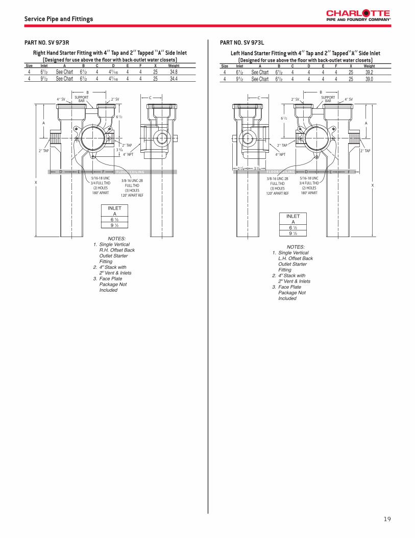
NOTES:1. Single Vertical R.H. Offset Back Outlet Starter Fitting2. 4”Stack with 2”Vent & Inlets3. Face Plate Package Not Included
PART NO. SV 973R
Right Hand Starter Fitting with 4” Tap and 2” Tapped “A” Side Inlet(Designed for use above the floor with back-outlet water closets)
Size Inlet A B C D E F X Weight
4 61⁄2 See Chart 61⁄2 4 41⁄16 4 4 25 34.8 4 91⁄2 See Chart 61⁄2 4 41⁄16 4 4 25 34.4
INLETA
6 1⁄29 1⁄2
NOTES:1. Single Vertical L.H. Offset Back Outlet Starter Fitting2. 4”Stack with 2”Vent & Inlets3. Face Plate Package Not Included
PART NO. SV 973L
Left Hand Starter Fitting with 4” Tap and 2” Tapped“A” Side Inlet(Designed for use above the floor with back-outlet water closets)
Size Inlet A B C D E F X Weight
4 61⁄2 See Chart 61⁄2 4 4 4 4 25 39.2 4 91⁄2 See Chart 61⁄2 4 4 4 4 25 39.0
INLETA
6 1⁄29 1⁄2
20
Cast Iron Service Submittal PackageService Pipe and Fittings
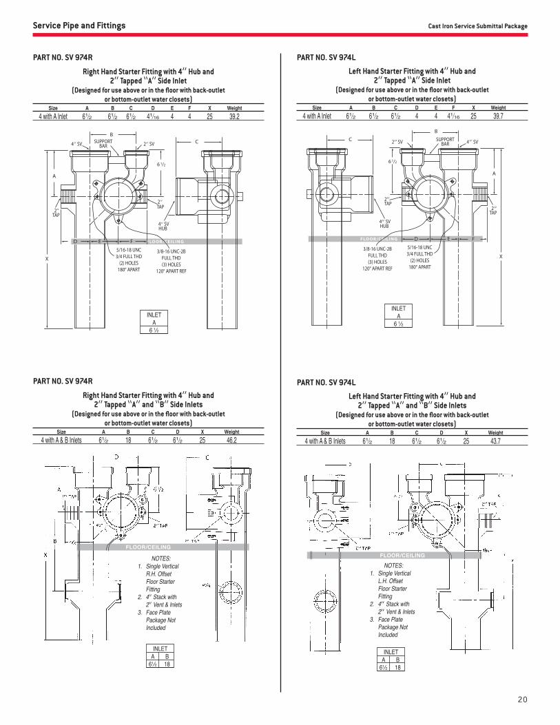
INLET A B 61⁄2 18
Right Hand Starter Fitting with 4” Hub and 2” Tapped “A” and “B” Side Inlets
(Designed for use above or in the floor with back-outlet or bottom-outlet water closets)
Size A B C D X Weight
4 with A & B Inlets 61⁄2 18 61⁄2 61⁄2 25 46.2
PART NO. SV 974R
NOTES:1. Single Vertical R.H. Offset Floor Starter Fitting2. 4” Stack with 2” Vent & Inlets3. Face Plate Package Not Included
FLOOR/CEILING
PART NO. SV 974R
Right Hand Starter Fitting with 4” Hub and 2” Tapped “A” Side Inlet
(Designed for use above or in the floor with back-outlet or bottom-outlet water closets)
Size A B C D E F X Weight
4 with A Inlet 61⁄2 61⁄2 61⁄2 41⁄16 4 4 25 39.2
INLETA
6 1⁄2
NOTES:1. Single Vertical L.H. Offset Floor Starter Fitting2. 4” Stack with 2” Vent & Inlets3. Face Plate Package Not Included
INLET A B 61⁄2 18
Left Hand Starter Fitting with 4” Hub and 2” Tapped “A” and “B” Side Inlets
(Designed for use above or in the floor with back-outlet or bottom-outlet water closets)
Size A B C D X Weight
4 with A & B Inlets 61⁄2 18 61⁄2 61⁄2 25 43.7
PART NO. SV 974L
FLOOR/CEILING
PART NO. SV 974L
Left Hand Starter Fitting with 4” Hub and 2” Tapped “A” Side Inlet
(Designed for use above or in the floor with back-outlet or bottom-outlet water closets)
Size A B C D E F X Weight
4 with A Inlet 61⁄2 61⁄2 61⁄2 4 4 41⁄16 25 39.7
INLETA
6 1⁄2
21
Service Pipe and Fittings
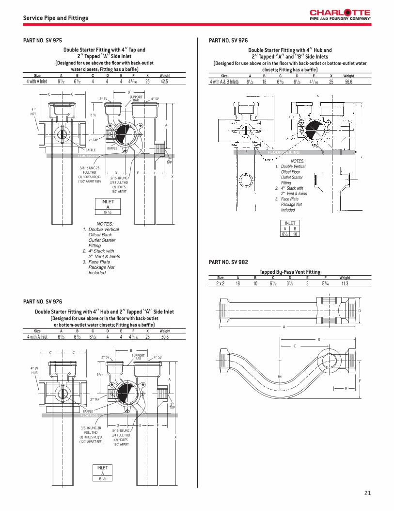
PART NO. SV 976
INLETA
6 1⁄2
Double Starter Fitting with 4” Hub and 2” Tapped “A” Side Inlet (Designed for use above or in the floor with back-outlet
or bottom-outlet water closets; Fitting has a baffle) Size A B C D E F X Weight
4 with A Inlet 61⁄2 61⁄2 61⁄2 4 4 41⁄16 25 50.8
NOTES:1. Double Vertical Offset Back Outlet Starter Fitting2. 4”Stack with 2” Vent & Inlets3. Face Plate Package Not Included
PART NO. SV 975
INLETA
9 1⁄2
Double Starter Fitting with 4” Tap and2” Tapped “A” Side Inlet
(Designed for use above the floor with back-outlet water closets; Fitting has a baffle)
Size A B C D E F X Weight
4 with A Inlet 91⁄2 61⁄2 4 4 4 41⁄16 25 42.5
INLET A B 61⁄2 18
Double Starter Fitting with 4” Hub and 2” Tapped “A” and “B” Side Inlets
(Designed for use above or in the floor with back-outlet or bottom-outlet water closets; Fitting has a baffle)
Size A B C D E X Weight
4 with A & B Inlets 61⁄2 18 61⁄2 61⁄2 41⁄16 25 56.6
PART NO. SV 976
NOTES:1. Double Vertical Offset Floor Outlet Starter Fitting2. 4” Stack with 2” Vent & Inlets3. Face Plate Package Not Included
FLOOR/CEILING
PART NO. SV 982
Tapped By-Pass Vent Fitting Size A B C D E F Weight
2 x 2 18 10 61⁄2 31⁄2 3 51⁄4 11.3
22
Cast Iron Service Submittal PackageService Pipe and Fittings
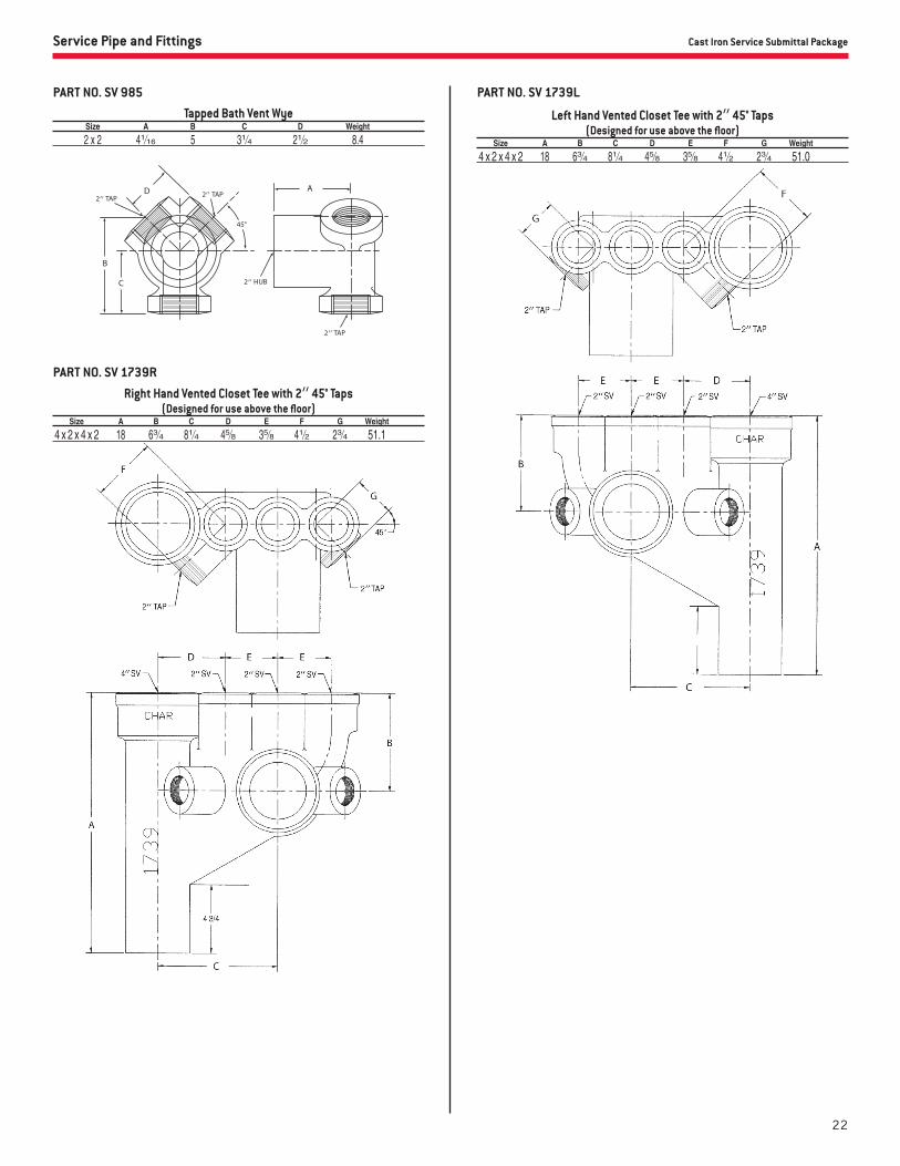
PART NO. SV 985
Tapped Bath Vent Wye Size A B C D Weight
2 x 2 41⁄16 5 31⁄4 21⁄2 8.4
PART NO. SV 1739R
Right Hand Vented Closet Tee with 2” 45° Taps(Designed for use above the floor)
Size A B C D E F G Weight
4 x 2 x 4 x 2 18 63⁄4 81⁄4 45⁄8 35⁄8 41⁄2 23⁄4 51.1
PART NO. SV 1739L
Left Hand Vented Closet Tee with 2” 45° Taps (Designed for use above the floor)
Size A B C D E F G Weight
4 x 2 x 4 x 2 18 63⁄4 81⁄4 45⁄8 35⁄8 41⁄2 23⁄4 51.0
23
Service Pipe and Fittings
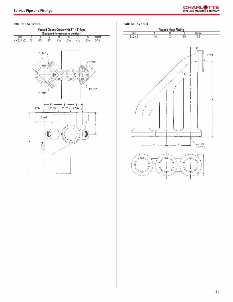
PART NO. SV 1739 D
Vented Closet Cross with 2” 45° Taps(Designed for use above the floor)
Size A B C D E F G Weight
4 x 2 x 4 x 2 18 63⁄4 81⁄4 45⁄8 35⁄8 41⁄2 23⁄4 57.5
PART NO. SV 1801
Tapped Harp Fitting Size A B C Weight
2 x 2 x 2 117⁄16 2 35⁄8 15.5
24
Cast Iron Service Submittal Package
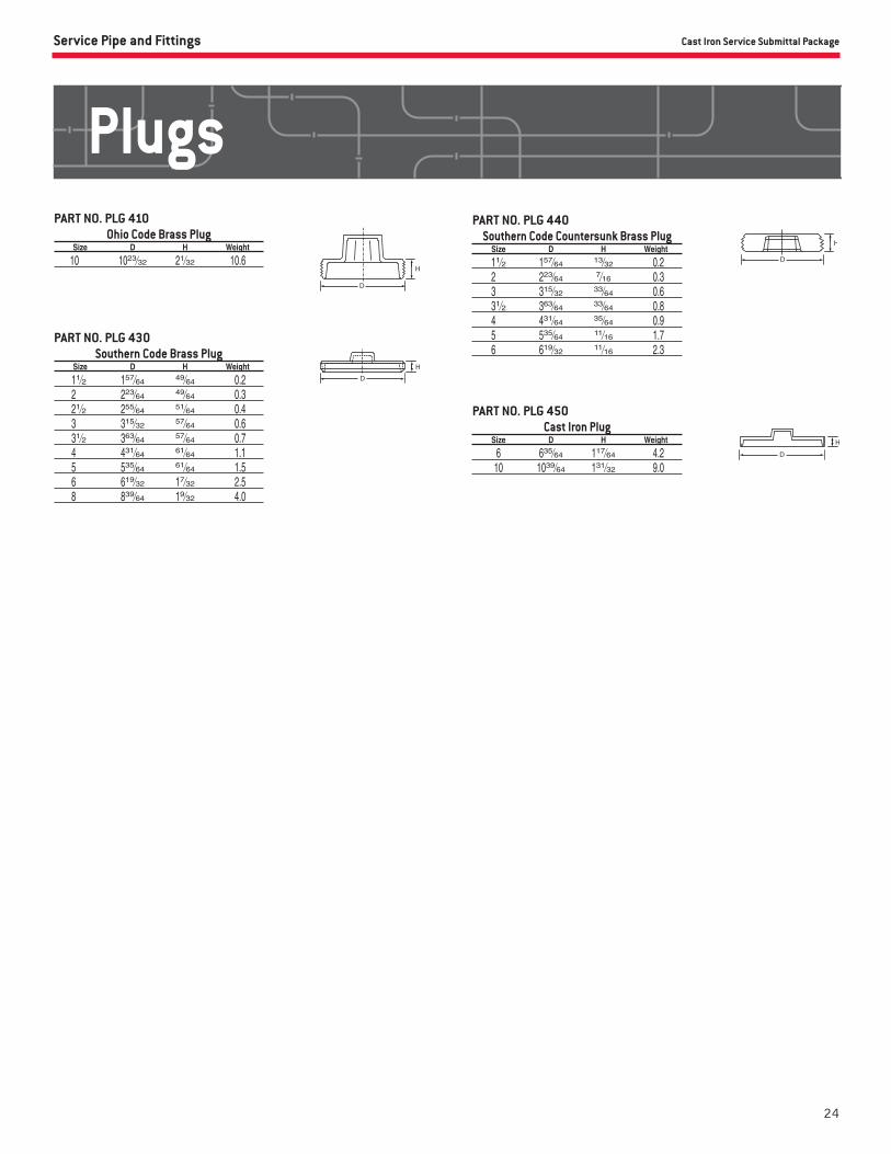
Ohio Code Brass Plug Size D H Weight
10 1023⁄32 21⁄32 10.6
PART NO. PLG 410
Southern Code Brass Plug Size D H Weight
11⁄2 157⁄64 49⁄64 0.2 2 223⁄64 49⁄64 0.3 21⁄2 255⁄64 51⁄64 0.4 3 315⁄32 57⁄64 0.6 31⁄2 363⁄64 57⁄64 0.7 4 431⁄64 61⁄64 1.1 5 535⁄64 61⁄64 1.5 6 619⁄32 17⁄32 2.5 8 839⁄64 19⁄32 4.0
PART NO. PLG 430
Southern Code Countersunk Brass Plug Size D H Weight
11⁄2 157⁄64 13⁄32 0.2 2 223⁄64 7⁄16 0.3 3 315⁄32 33⁄64 0.6 31⁄2 363⁄64 33⁄64 0.8 4 431⁄64 35⁄64 0.9 5 535⁄64 11⁄16 1.7 6 619⁄32 11⁄16 2.3
PART NO. PLG 440
Cast Iron Plug Size D H Weight
6 635⁄64 117⁄64 4.2 10 1039⁄64 131⁄32 9.0
PART NO. PLG 450
Service Pipe and Fittings
Plugs
25
For more information, call us at 1-800-438-6091 or log on to www.charlottepipe.com.
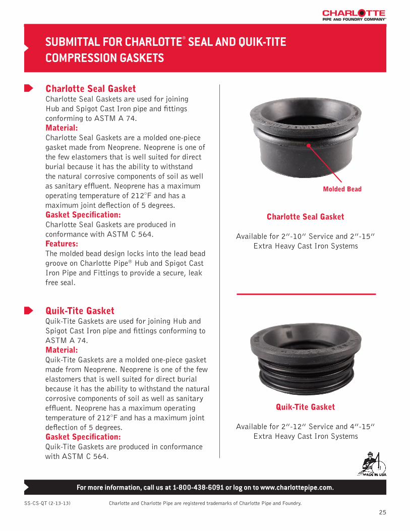
SUBMITTAL FOR CHARLOTTE® SEAL AND QUIK-TITE COMPRESSION GASKETS
Charlotte Seal GasketCharlotte Seal Gaskets are used for joining Hub and Spigot Cast Iron pipe and fittings conforming to ASTM A 74.Material:Charlotte Seal Gaskets are a molded one-piece gasket made from Neoprene. Neoprene is one of the few elastomers that is well suited for direct burial because it has the ability to withstand the natural corrosive components of soil as well as sanitary effluent. Neoprene has a maximum operating temperature of 212°F and has a maximum joint deflection of 5 degrees.Gasket Specification:Charlotte Seal Gaskets are produced in conformance with ASTM C 564.Features:The molded bead design locks into the lead bead groove on Charlotte Pipe® Hub and Spigot Cast Iron Pipe and Fittings to provide a secure, leak free seal.
Quik-Tite GasketQuik-Tite Gaskets are used for joining Hub and Spigot Cast Iron pipe and fittings conforming to ASTM A 74.Material:Quik-Tite Gaskets are a molded one-piece gasket made from Neoprene. Neoprene is one of the few elastomers that is well suited for direct burial because it has the ability to withstand the natural corrosive components of soil as well as sanitary effluent. Neoprene has a maximum operating temperature of 212°F and has a maximum joint deflection of 5 degrees.Gasket Specification:Quik-Tite Gaskets are produced in conformance with ASTM C 564.
Charlotte Seal Gasket
Available for 2”-10” Service and 2”-15” Extra Heavy Cast Iron Systems
Quik-Tite Gasket
Available for 2”-12” Service and 4”-15” Extra Heavy Cast Iron Systems
Molded Bead
SS-CS-QT (2-13-13) Charlotte and Charlotte Pipe are registered trademarks of Charlotte Pipe and Foundry.
26
Cast Iron Service Submittal Package
For more information, call us at 1-800-438-6091 or log on to www.charlottepipe.com.
SUBMITTAL FOR CHARLOTTE® SEAL AND QUIK-TITE COMPRESSION GASKETS
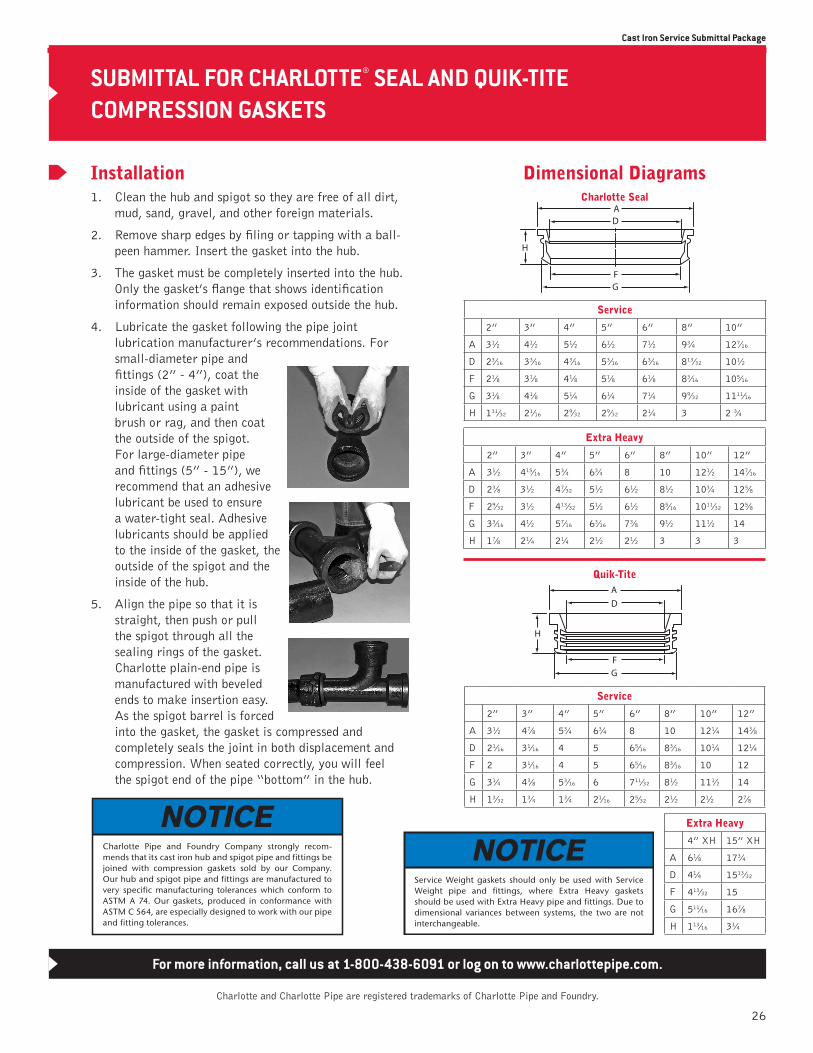
Installation1. Clean the hub and spigot so they are free of all dirt,
mud, sand, gravel, and other foreign materials.
2. Remove sharp edges by filing or tapping with a ball-peen hammer. Insert the gasket into the hub.
3. The gasket must be completely inserted into the hub. Only the gasket’s flange that shows identification information should remain exposed outside the hub.
4. Lubricate the gasket following the pipe joint lubrication manufacturer’s recommendations. For small-diameter pipe and fittings (2” - 4”), coat the inside of the gasket with lubricant using a paint brush or rag, and then coat the outside of the spigot. For large-diameter pipe and fittings (5” - 15”), we recommend that an adhesive lubricant be used to ensure a water-tight seal. Adhesive lubricants should be applied to the inside of the gasket, the outside of the spigot and the inside of the hub.
5. Align the pipe so that it is straight, then push or pull the spigot through all the sealing rings of the gasket. Charlotte plain-end pipe is manufactured with beveled ends to make insertion easy. As the spigot barrel is forced into the gasket, the gasket is compressed and completely seals the joint in both displacement and compression. When seated correctly, you will feel the spigot end of the pipe “bottom” in the hub.
GF
DA
H
H
GF
A
D
Service
2” 3” 4” 5” 6” 8” 10”
A 31⁄2 41⁄2 51⁄2 61⁄2 71⁄2 93⁄4 127⁄16
D 23⁄16 33⁄16 43⁄16 53⁄16 63⁄16 813⁄32 101⁄2
F 21⁄8 31⁄8 41⁄8 51⁄8 61⁄8 83⁄16 105⁄16
G 31⁄8 41⁄8 51⁄4 61⁄4 71⁄4 99⁄32 1111⁄16
H 131⁄32 21⁄16 29⁄32 29⁄32 21⁄4 3 2 3⁄4
Extra Heavy
2” 3” 4” 5” 6” 8” 10” 12”
A 31⁄2 415⁄16 53⁄4 63⁄4 8 10 121⁄2 147⁄16
D 23⁄8 31⁄2 47⁄32 51⁄2 61⁄2 81⁄2 103⁄4 125⁄8
F 29⁄32 31⁄2 413⁄32 51⁄2 61⁄2 85⁄16 1011⁄32 125⁄8
G 33⁄16 41⁄2 57⁄16 63⁄16 73⁄8 91⁄2 111⁄2 14
H 17⁄8 21⁄4 21⁄4 21⁄2 21⁄2 3 3 3
Service
2” 3” 4” 5” 6” 8” 10” 12”
A 31⁄2 47⁄8 53⁄4 63⁄4 8 10 121⁄4 143⁄8
D 21⁄16 31⁄16 4 5 65⁄16 83⁄16 101⁄4 121⁄4
F 2 31⁄16 4 5 65⁄16 83⁄16 10 12
G 31⁄4 43⁄8 53⁄16 6 711⁄32 81⁄2 111⁄2 14
H 13⁄32 13⁄4 13⁄4 21⁄16 25⁄32 21⁄2 21⁄2 27⁄8
Extra Heavy
4” XH 15” XH
A 61⁄8 173⁄4
D 41⁄4 1513⁄32
F 413⁄32 15
G 511⁄16 167⁄8
H 113⁄16 31⁄4
Dimensional DiagramsCharlotte Seal
Quik-Tite
Charlotte Pipe and Foundry Company strongly recom-mends that its cast iron hub and spigot pipe and fittings be joined with compression gaskets sold by our Company. Our hub and spigot pipe and fittings are manufactured to very specific manufacturing tolerances which conform to ASTM A 74. Our gaskets, produced in conformance with ASTM C 564, are especially designed to work with our pipe and fitting tolerances.
Service Weight gaskets should only be used with Service Weight pipe and fittings, where Extra Heavy gaskets should be used with Extra Heavy pipe and fittings. Due to dimensional variances between systems, the two are not interchangeable.
Charlotte and Charlotte Pipe are registered trademarks of Charlotte Pipe and Foundry.
27
Limited Warranty
Charlotte Pipe and Foundry Company® (Charlotte Pipe®) Products are warranted to be free from manufacturing defects and to conform to currently applicable ASTM standards for a period of five (5) years from date of delivery. Buyer’s remedy for breach of this warranty is limited to replacement of, or credit for, the defective product. This warranty excludes any expense for removal or reinstallation of any defective product and any other incidental, consequential, or punitive damages. This limited warranty is the only warranty made by seller and is expressly in lieu of all other warranties, express and implied, including any warranties of merchantability and fitness for a particular purpose. No statement, conduct or description by Charlotte Pipe or its representative, in addition to or beyond this Limited Warranty, shall constitute a warranty. This Limited Warranty may only be modified in writing signed by an officer of Charlotte Pipe.This Limited Warranty will not apply if:1) The Products are used for purposes other than their
intended purpose as defined by local plumbing and building codes, and the applicable ASTM standard.
2) The Products are not installed in good and workmanlike manner consistent with normal industry standards; installed in compliance with the latest instructions published by Charlotte Pipe and good plumbing practices; and installed in conformance with all applicable plumbing, fire and building code requirements.
3) This limited warranty does not apply when the products of Charlotte Pipe are used with the products of other manufacturers that do not meet the applicable ASTM or CISPI standards or that are not marked in a manner to indicate the entity that manufactured them.
4) In hubless cast iron installations, this warranty will not apply if products are joined with unshielded hubless couplings. Charlotte Pipe requires that its hubless cast iron pipe and fittings be joined only with shielded hubless couplings manufactured in accordance with CISPI 310, ASTM C 1277 and certified by NSF® International or with Heavy Duty Couplings meeting ASTM C 1540.
5) The Products fail due to defects or deficiencies in design, engineering, or installation of the piping system of which they are a part.
6) The Products have been the subject of modification; misuse; misapplication; improper maintenance or repair; damage caused by the fault or negligence of anyone other than Charlotte Pipe; or any other act or event beyond the control of Charlotte Pipe.
7) The Products fail due to the freezing of water in the Products.
8) The Products fail due to contact with chemical agents, fire stopping materials, thread sealant, plasticized vinyl products, or other aggressive chemical agents that are not compatible.
9) Pipe outlets, sound attenuation systems or other devices are permanently attached to the surface of Charlotte® PVC, ABS or CPVC products with solvent cement or adhesive glue.
Charlotte Pipe products are manufactured to the applicable ASTM or CISPI standard. Charlotte Pipe and Foundry cannot accept responsibility for the performance, dimensional accuracy, or compatibility of pipe, fittings, gaskets, or couplings not manufactured or sold by Charlotte Pipe and Foundry. Any Charlotte Pipe products alleged to be defective must be made available to Charlotte Pipe at the following address for verification, inspection and determination of cause:
Charlotte Pipe and Foundry CompanyAttention: Technical Services
2109 Randolph RoadCharlotte, North Carolina 28207
Purchaser must obtain a return materials authorization and instructions for return shipment to Charlotte Pipe of any product claimed defective or shipped in error. Please refer to the Return Material Policy on the back of this page for specific instructions on returning materials to Charlotte Pipe.Any Charlotte Pipe product proved to be defective in manufacture will be replaced F.O.B. point of original delivery, or credit will be issued, at the discretion of Charlotte Pipe.
4/24/15
PO Box 35430 Charlotte, NC 28235 USA 704/348-6450 800/572-4199 FAX 800/553-1605 www.charlottepipe.com
Charlotte Pipe and Charlotte are registered trademarks of Charlotte Pipe and Foundry Company. © 1901-2017 Charlotte Pipe and Foundry Company
WA (1-17-17)
PO BOX 35430
CHARLOTTE
NORTH CAROLINA 28235
PHONE (704) 348-6450
(800) 438-6091
FAX (800) 553-1605
WWW.CHARLOTTEPIPE.COM
All products manufactured by Charlotte Pipe and Foundry Company
are proudly made in the U.S.A.