submittal package cast iron no-hub system · composition of gray iron the following are typical...
TRANSCRIPT

1
SUBMITTAL PACKAGE
Submittal Package Cast Iron No-Hub System
(Updated May 18, 2018)
© 2018 Charlotte Pipe and Foundry Company
SUB-PAC-CI-NH
2
Cast Iron No-Hub Submittal Package
Page
Submittal Form for Cast Iron No-Hub Pipe & Fittings ..............................................................................3
Certifications ..........................................................................................................................................4
ASTM & CISPI Reference Standards .......................................................................................................5
Gray Iron Properties & Composition .........................................................................................................6
Dimensional Information ....................................................................................................................7-24
Submittal Form for Charlotte Standard No-Hub Couplings ................................................................25-26
Submittal Form for Charlotte Heavy-Duty (MD) No-Hub Couplings ....................................................27-28
Submittal Form for Charlotte Heavy-Duty (HD) No-Hub Couplings .....................................................29-30
Submittal Form for Charlotte 12” and 15” Heavy-Duty No-Hub Couplings.........................................31-32
Limited Warranty ..................................................................................................................................33
Table of Contents forCast Iron No-Hub Submittal Package
3
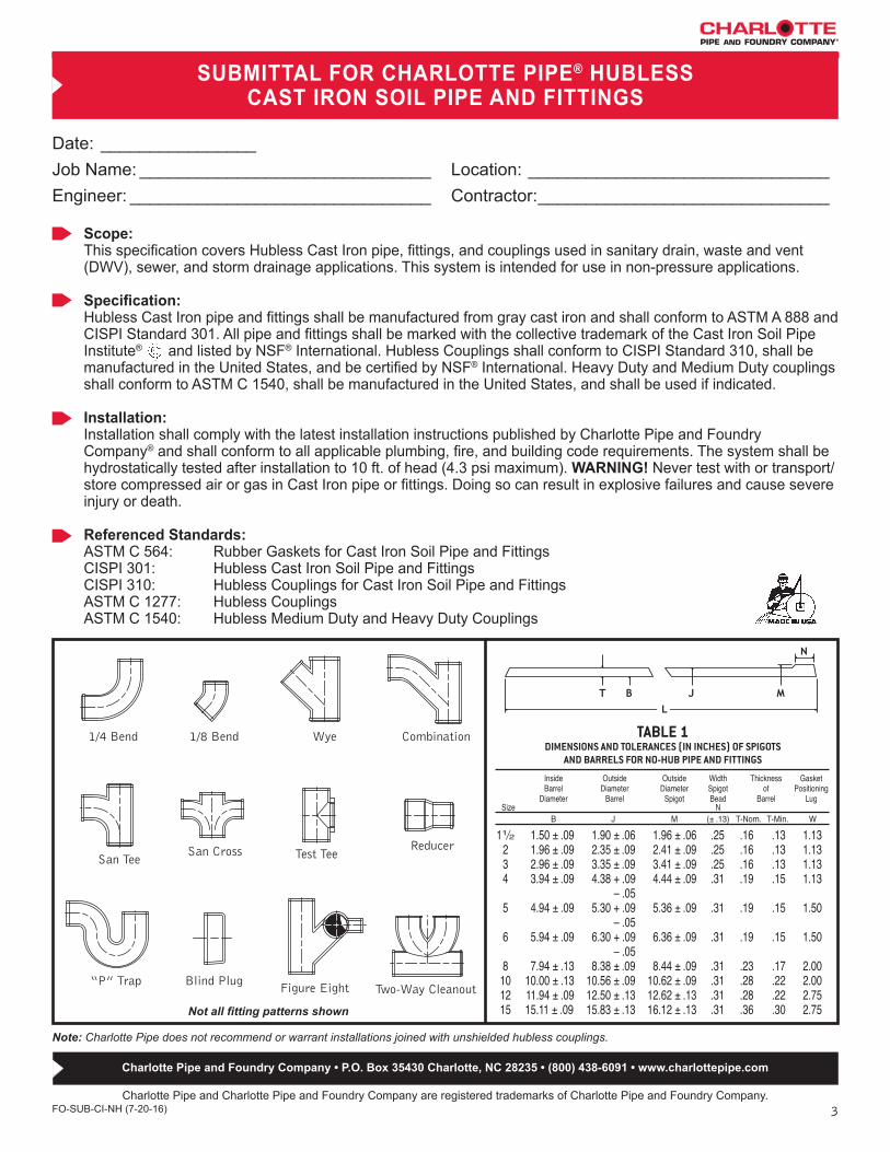
SUBMITTAL FOR CHARLOTTE PIPE® HUBLESS CAST IRON SOIL PIPE AND FITTINGS
Charlotte Pipe and Charlotte Pipe and Foundry Company are registered trademarks of Charlotte Pipe and Foundry Company.FO-SUB-CI-NH (7-20-16)
Date: ________________Job Name: ______________________________ Location: _______________________________Engineer: _______________________________ Contractor: ______________________________
Scope: This specification covers Hubless Cast Iron pipe, fittings, and couplings used in sanitary drain, waste and vent (DWV), sewer, and storm drainage applications. This system is intended for use in non-pressure applications.
Specification: Hubless Cast Iron pipe and fittings shall be manufactured from gray cast iron and shall conform to ASTM A 888 and CISPI Standard 301. All pipe and fittings shall be marked with the collective trademark of the Cast Iron Soil Pipe Institute® and listed by NSF® International. Hubless Couplings shall conform to CISPI Standard 310, shall be manufactured in the United States, and be certified by NSF® International. Heavy Duty and Medium Duty couplings shall conform to ASTM C 1540, shall be manufactured in the United States, and shall be used if indicated.
Installation: Installation shall comply with the latest installation instructions published by Charlotte Pipe and Foundry Company® and shall conform to all applicable plumbing, fire, and building code requirements. The system shall be hydrostatically tested after installation to 10 ft. of head (4.3 psi maximum). WARNING! Never test with or transport/store compressed air or gas in Cast Iron pipe or fittings. Doing so can result in explosive failures and cause severe injury or death.
Referenced Standards: ASTM C 564: Rubber Gaskets for Cast Iron Soil Pipe and FittingsCISPI 301: Hubless Cast Iron Soil Pipe and FittingsCISPI 310: Hubless Couplings for Cast Iron Soil Pipe and FittingsASTM C 1277: Hubless CouplingsASTM C 1540: Hubless Medium Duty and Heavy Duty Couplings
Not all fitting patterns shown
Two-Way Cleanout
Test Tee
Blind Plug“P” Trap
ReducerSan Tee
CombinationWye1/8 Bend1/4 Bend
San Cross
Figure Eight
Note: Charlotte Pipe does not recommend or warrant installations joined with unshielded hubless couplings.
TABLE 1DIMENSIONS AND TOLERANCES (IN INCHES) OF SPIGOTS
AND BARRELS FOR NO-HUB PIPE AND FITTINGS
Inside Outside Outside Width Thickness Gasket Barrel Diameter Diameter Spigot of Positioning Diameter Barrel Spigot Bead Barrel Lug Size N B J M (± .13) T-Nom. T-Min. W 11⁄2 1.50 ± .09 1.90 ± .06 1.96 ± .06 .25 .16 .13 1.13 2 1.96 ± .09 2.35 ± .09 2.41 ± .09 .25 .16 .13 1.13 3 2.96 ± .09 3.35 ± .09 3.41 ± .09 .25 .16 .13 1.13 4 3.94 ± .09 4.38 + .09 4.44 ± .09 .31 .19 .15 1.13 – .05 5 4.94 ± .09 5.30 + .09 5.36 ± .09 .31 .19 .15 1.50 – .05 6 5.94 ± .09 6.30 + .09 6.36 ± .09 .31 .19 .15 1.50 – .05 8 7.94 ± .13 8.38 ± .09 8.44 ± .09 .31 .23 .17 2.00 10 10.00 ± .13 10.56 ± .09 10.62 ± .09 .31 .28 .22 2.00 12 11.94 ± .09 12.50 ± .13 12.62 ± .13 .31 .28 .22 2.75 15 15.11 ± .09 15.83 ± .13 16.12 ± .13 .31 .36 .30 2.75
Charlotte Pipe and Foundry Company • P.O. Box 35430 Charlotte, NC 28235 • (800) 438-6091 • www.charlottepipe.com
4
Cast Iron No-Hub Submittal Package
Very truly yours,
Hooper Hardison, President
Notary Public My commission expires July 02, 2022
LC-Cl (6-28-17)
TERRI L WILSON NOTARY PUBLIC
UNION COUNTY, NC My Commission Expires 7-2-2022
PO Box 35430 Charlotte, NC 28235 USA 704/372-5030 800/438-6091 FAX 800/553-1605
www.charlottepipe.com
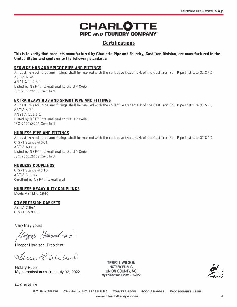
This is to verify that products manufactured by Charlotte Pipe and Foundry, Cast Iron Division, are manufactured in the United States and conform to the following standards:
SERVICE HUB AND SPIGOT PIPE AND FITTINGSAll cast iron soil pipe and fittings shall be marked with the collective trademark of the Cast Iron Soil Pipe Institute (CISPI).ASTM A 74ANSI A 112.5.1Listed by NSF® International to the UP CodeISO 9001:2008 Certified
EXTRA HEAVY HUB AND SPIGOT PIPE AND FITTINGSAll cast iron soil pipe and fittings shall be marked with the collective trademark of the Cast Iron Soil Pipe Institute (CISPI).ASTM A 74ANSI A 112.5.1Listed by NSF® International to the UP CodeISO 9001:2008 Certified
HUBLESS PIPE AND FITTINGSAll cast iron soil pipe and fittings shall be marked with the collective trademark of the Cast Iron Soil Pipe Institute (CISPI).CISPI Standard 301ASTM A 888Listed by NSF® International to the UP CodeISO 9001:2008 Certified
HUBLESS COUPLINGSCISPI Standard 310ASTM C 1277Certified by NSF® International
HUBLESS HEAVY DUTY COUPLINGSMeets ASTM C 1540
COMPRESSION GASKETSASTM C 564CISPI HSN 85
Certifications
Very truly yours,
Hooper Hardison, President
Notary Public My commission expires July 02, 2022
LC-Cl (6-28-17)
TERRI L WILSON NOTARY PUBLIC
UNION COUNTY, NC My Commission Expires 7-2-2022
PO Box 35430 Charlotte, NC 28235 USA 704/372-5030 800/438-6091 FAX 800/553-1605
www.charlottepipe.com

5
AMERICAN SOCIETY FOR TESTING AND MATERIALS
ASTM TITLE
A 74 SPECIFICATION FOR CAST IRON SOIL PIPE AND FITTINGS HUB AND SPIGOT (SERVICE AND EXTRA HEAVY)
SCOPE: THIS SPECIFICATION COVERS CAST IRON PIPE AND FITTINGS USED IN SANITARY DRAIN, WASTE, AND VENT (DWV), SEWER, AND STORM DRAINAGE APPLICATION. THIS SYSTEM IS INTENDED FOR USE IN NONPRESSURE APPLICATIONS.
C 564 SPECIFICATION FOR RUBBER GASKETS FOR CAST IRON SOIL PIPE AND FITTINGSSCOPE: THIS SPECIFICATION COVERS PREFORMED RUBBER GASKETS USED TO SEAL JOINTS IN CAST
IRON SOIL PIPE AND FITTINGS.
C 1277 SPECIFICATION FOR COUPLING FOR USE IN CONNECTION WITH HUBLESS CAST IRON PIPE AND FITTINGS FOR SANITARY AND STORM DRAIN, WASTE, AND VENT PIPING APPLICATION (REGULAR HUBLESS COUPLING)
SCOPE: THE PURPOSE OF THIS SPECIFICATION IS TO ESTABLISH CRITERIA FOR MATERIAL DIMENSIONS AND TOLERANCES FOR ONE TYPE OF COUPLING USED IN HUBLESS CAST IRON SOIL PIPE AND FITTING FOR SANITARY AND STORM DRAIN, WASTE AND VENT PIPING APPLICATIONS.
C 1540 SPECIFICATION FOR SHIELDED COUPLINGS JOINING HUBLESS CAST IRON SOIL PIPE AND FITTINGS (HEAVY DUTY COUPLINGS)
SCOPE: THIS SPECIFICATION COVERS THE EVALUATION OF THE PERFORMANCE OF SHIELDED HUBLESS COUPLINGS TO JOIN CAST IRON SOIL PIPE AND FITTINGS.
CAST IRON SOIL PIPE INSTITUTE
CISPI TITLE
301 SPECIFICATION FOR HUBLESS CAST IRON SOIL PIPE AND FITTINGS FOR SANITARY AND STORM DRAIN, WASTE, AND VENT PIPING APPLICATIONS
SCOPE: THE PURPOSE OF THIS STANDARD IS TO ESTABLISH STANDARDS COVERING MATERIAL, DIMENSIONS, AND TOLERANCE FOR PIPE AND FITTINGS FOR HUBLESS CAST IRON SANITARY AND STORM DRAIN, SANITARY WASTE, AND VENT PIPING APPLICATIONS.
310 SPECIFICATION FOR COUPLING FOR USE IN CONNECTION WITH HUBLESS CAST IRON PIPE AND FITTINGS FOR SANITARY AND STORM DRAIN, WASTE, AND VENT PIPING APPLICATION (REGULAR HUBLESS COUPLING)
SCOPE: THE PURPOSE OF THIS SPECIFICATION IS TO ESTABLISH CRITERIA FOR MATERIAL DIMENSIONS AND TOLERANCES FOR ONE TYPE OF COUPLING USED IN HUBLESS CAST IRON SOIL PIPE AND FITTING FOR SANITARY AND STORM DRAIN, WASTE AND VENT PIPING APPLICATIONS.
Reference Standards Cast Iron

6
Cast Iron No-Hub Submittal Package
Gray Iron Physical Properties
Tensile Strength 20,000 p.s.i. — 60,000 p.s.i. (21,000 p.s.i.)
Elastic Modulus 10 - 23 x 106 p.s.i.(Young’s modulus)
Hardness (Brinell) 150 - 250 BHN
Thermal Conductivity 0.110 - 0.137 calories/cm2/Sec/cm/ °C
Thermal Expansion 10 x 10-6 / °C 6 x 10⁻⁶ / °F
Density 0.25 - 0.28 lb./in3
6.95 - 7.35 gm/cm3
Specific Heat 0.13 BTU / lb / °F 0.13 cal / gm / °C
Composition of Gray Iron
The following are typical ranges of elements present in unalloyed gray cast iron normally produced in commercial practice:
Carbon (C) 2.60 - 3.85%
Silicon (Si) 1.25 - 2.90%
Manganese (Mn) 0.40 - 1.00%
Phosphorus (P) 0.02 - 0.90%
Sulfur (S) 0.04 - 0.20%
7
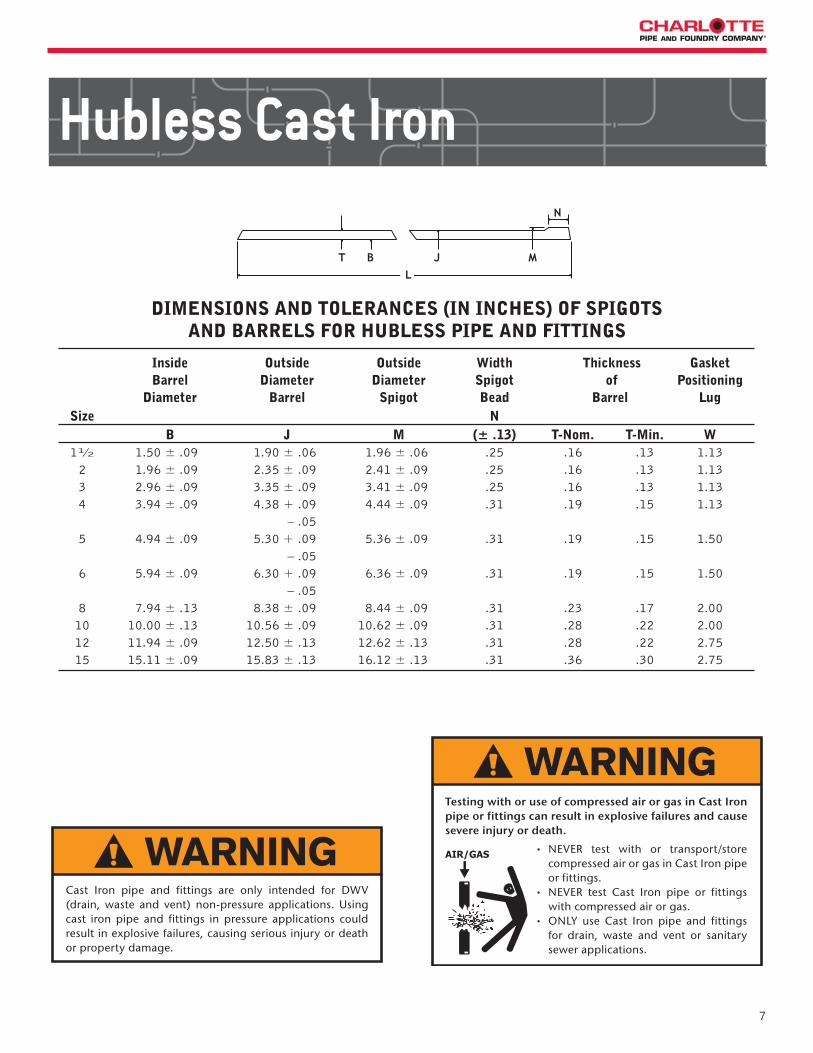
DIMENSIONS AND TOLERANCES (IN INCHES) OF SPIGOTSAND BARRELS FOR HUBLESS PIPE AND FITTINGS
Inside Outside Outside Width Thickness Gasket Barrel Diameter Diameter Spigot of Positioning Diameter Barrel Spigot Bead Barrel Lug Size N B J M (± .13) T-Nom. T-Min. W 11⁄2 1.50 ± .09 1.90 ± .06 1.96 ± .06 .25 .16 .13 1.13 2 1.96 ± .09 2.35 ± .09 2.41 ± .09 .25 .16 .13 1.13 3 2.96 ± .09 3.35 ± .09 3.41 ± .09 .25 .16 .13 1.13 4 3.94 ± .09 4.38 + .09 4.44 ± .09 .31 .19 .15 1.13 – .05 5 4.94 ± .09 5.30 + .09 5.36 ± .09 .31 .19 .15 1.50 – .05 6 5.94 ± .09 6.30 + .09 6.36 ± .09 .31 .19 .15 1.50 – .05 8 7.94 ± .13 8.38 ± .09 8.44 ± .09 .31 .23 .17 2.00 10 10.00 ± .13 10.56 ± .09 10.62 ± .09 .31 .28 .22 2.00 12 11.94 ± .09 12.50 ± .13 12.62 ± .13 .31 .28 .22 2.75 15 15.11 ± .09 15.83 ± .13 16.12 ± .13 .31 .36 .30 2.75
Hubless Cast Iron
• NEVER test with or transport/store compressed air or gas in Cast Iron pipe or fittings.
• NEVER test Cast Iron pipe or fittings with compressed air or gas.
• ONLY use Cast Iron pipe and fittings for drain, waste and vent or sanitary sewer applications.
Testing with or use of compressed air or gas in Cast Iron pipe or fittings can result in explosive failures and cause severe injury or death.
Cast Iron pipe and fittings are only intended for DWV (drain, waste and vent) non-pressure applications. Using cast iron pipe and fittings in pressure applications could result in explosive failures, causing serious injury or death or property damage.

8
Cast Iron No-Hub Submittal Package
Hubless Cast Iron
Part No. NH 2No-Hub (Hubless) Pipe
Size Weight 11⁄2”x10’ 28.5 2”x10’ 37.1 3”x10’ 54.0 4”x10’ 71.2 5”x10’ 97.6 6”x10’ 117.8 8”x10’ 170.9 10”x10’ 254.6 12”x10’ 318.1 15”x10’ 492.6
• NEVER test with or transport/store compressed air or gas in Cast Iron pipe or fittings.
• NEVER test Cast Iron pipe or fittings with compressed air or gas.
• ONLY use Cast Iron pipe and fittings for drain, waste and vent or sanitary sewer applications.
Testing with or use of compressed air or gas in Cast Iron pipe or fittings can result in explosive failures and cause severe injury or death.
Hubless Cast Iron Soil Pipe
Cast Iron pipe and fittings are only intended for DWV (drain, waste and vent) non-pressure applications. Using cast iron pipe and fittings in pressure applications could result in explosive failures, causing serious injury or death or property damage.
9
No-Hub Pipe and Fittings
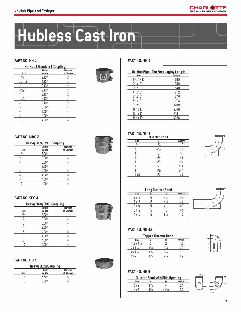
Long Quarter Bend Size D E Weight
2 x 12 12 41⁄2 5.4 2 x 18 18 41⁄2 8.8 2 x 24 24 41⁄2 10.7 3 x 12 12 5 8.5 4 x 12 12 51⁄2 11.2
No-Hub (Standard) Coupling Shield Number Size Width of Clamps
11⁄2 2.13” 2 2 x 11⁄2 2.13” 2 2 2.13” 2 3 x 2 2.13” 2 3 2.13” 2 4 x 3 2.13” 2 4 2.13” 2 5 3.00” 4 6 3.00” 4 8 4.00” 4 10 4.00” 4
No-Hub Pipe - Ten Feet Laying Length Size Weight
11⁄2” x 10’ 28.5 2” x 10’ 35.0 3” x 10’ 54.0 4” x 10’ 71.2 5” x 10’ 97.6 6” x 10’ 117.8 8” x 10’ 170.9 10” x 10’ 254.6 12” x 10’ 318.1 15” x 10’ 492.6
Quarter Bend Size D Weight
11⁄2 41⁄4 1.7 2 41⁄2 2.2 3 5 3.7 4 51⁄2 6.5 5 61⁄2 9.3 6 7 15.0 8 81⁄2 23.1 4 x 3 51⁄2 5.5
PART NO. NH 1 PART NO. NH 2
PART NO. NH 4
Heavy Duty (HD) Coupling Shield Number Size Width of Clamps
11⁄2 3.00” 4 2 3.00” 4 3 3.00” 4 4 3.00” 4 5 4.00” 6 6 4.00” 6 8 4.00” 6 10 4.00” 6
PART NO. SDC 4
Heavy Duty (MD) Coupling Shield Number Size Width of Clamps
11⁄2 3.00” 4 2 3.00” 4 3 3.00” 4 4 3.00” 4 5 4.00” 6 6 4.00” 6 8 4.00” 6 10 4.00” 6
PART NO. MDC 2
Heavy Duty Coupling Shield Number Size Width of Clamps
12 5.50” 6 15 5.50” 6
PART NO. HD 1
Quarter Bend with Side Opening Size E D Weight
3 x 2 31⁄4 4 5.1 4 x 2 33⁄4 45⁄16 7.5
PART NO. NH 6
Tapped Quarter Bend Size D E Weight
11⁄2 x 11⁄2 3 2 1.9 2 x 11⁄4 31⁄4 21⁄4 2.0 2 x 11⁄2 31⁄4 21⁄4 1.8 2 x 2 31⁄4 21⁄4 2.9
PART NO. NH 4A
Hubless Cast Iron

10
Cast Iron No-Hub Submittal PackageNo-Hub Pipe and Fittings
Double Quarter Bend Size D Weight
2 41⁄2 4.5 3 5 7.1 4 51⁄2 9.7
Eighth Bend Size D Weight
11⁄2 25⁄8 1.5 2 23⁄4 1.5 3 3 2.9 4 31⁄8 4.0 5 37⁄8 7.4 6 41⁄16 9.1 8 5 14.9 10 515⁄16 31.7 12 69⁄16 31.6 15 713⁄16 62.0
Sixth Bend Size D Weight
2 31⁄4 2.2 3 31⁄2 3.0 4 313⁄16 5.3
Fifth Bend Size D Weight
2 311⁄16 2.3 3 41⁄16 3.7 4 47⁄16 6.1
PART NO. NH 12
PART NO. NH 10
PART NO. NH 9
PART NO. NH 8A
Quarter Bend with Heel Opening Size D E Weight
3 x 2 5 27⁄8 5.6 4 x 2 51⁄2 31⁄4 7.2
PART NO. NH 8
Extended Quarter Bend with Low Heel Outlet
Size D E Weight
3 x 2 5 101⁄2 7.8
PART NO. NH 8B
Short Sweep Size D Weight
2 61⁄2 3.1 3 7 6.3 4 71⁄2 8.1 5 81⁄2 13.1 6 9 17.1 8 101⁄2 31.0 10 12 53.4 12 131⁄4 61.3 15 143⁄4 105.6
PART NO. NH 16
Sixteenth Bend Size D Weight
11⁄2 21⁄8 1.2 2 21⁄8 1.4 3 21⁄4 2.1 4 25⁄16 3.4 5 27⁄8 5.4 6 3 6.7 8 33⁄4 12.0
PART NO. NH 14
Long Eighth Bend Size D E Weight
2 x 12 12 23⁄4 4.6 2 x 18 18 23⁄4 7.3 3 x 12 12 3 8.0 3 x 18 18 3 10.2 4 x 12 12 31⁄8 9.7
PART NO. NH 12
Extended Short Sweep Size E F Weight
2 x 18 61⁄2 18 8.0 2 x 24 61⁄2 24 11.0 2 x 34 61⁄2 34 13.9
PART NO. EZS 14
11
No-Hub Pipe and Fittings
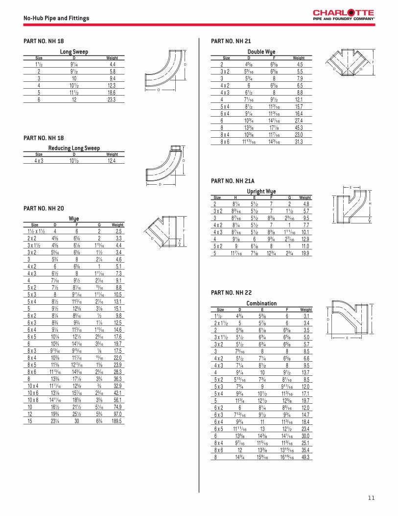
Long Sweep Size D Weight
11⁄2 91⁄4 4.4 2 91⁄2 5.8 3 10 9.4 4 101⁄2 12.3 5 111⁄2 18.6 6 12 23.3
PART NO. NH 18
Reducing Long Sweep Size D Weight
4 x 3 101⁄2 12.4
PART NO. NH 18
Double Wye Size D F Weight
2 45⁄8 65⁄8 4.5 3 x 2 55⁄16 65⁄8 5.5 3 53⁄4 8 7.9 4 x 2 6 65⁄8 6.5 4 x 3 61⁄2 8 8.8 4 71⁄16 91⁄2 12.1 5 x 4 81⁄2 113⁄16 15.7 6 x 4 91⁄4 113⁄16 16.4 6 103⁄4 141⁄16 27.4 8 133⁄8 171⁄8 45.3 8 x 4 103⁄8 117⁄16 23.0 8 x 6 1113⁄16 143⁄16 31.3
PART NO. NH 21
Wye Size D F G Weight
11⁄2 x 11⁄2 4 6 2 2.5 2 x 2 45⁄8 65⁄8 2 3.3 3 x 11⁄2 45⁄8 61⁄8 115⁄16 4.4 3 x 2 55⁄16 65⁄8 11⁄2 3.4 3 53⁄4 8 21⁄4 4.6 4 x 2 6 65⁄8 1 5.1 4 x 3 61⁄2 8 111⁄16 7.3 4 71⁄16 91⁄2 27⁄16 9.1 5 x 2 71⁄2 81⁄16 15⁄16 8.8 5 x 3 8 911⁄16 111⁄16 10.5 5 x 4 81⁄2 113⁄16 27⁄16 13.1 5 91⁄2 125⁄8 31⁄8 15.1 6 x 2 81⁄4 85⁄16 1⁄2 9.8 6 x 3 83⁄4 93⁄4 11⁄4 12.5 6 x 4 91⁄4 113⁄16 115⁄16 14.6 6 x 5 101⁄4 121⁄2 29⁄16 17.6 6 103⁄4 141⁄16 35⁄16 19.7 8 x 3 913⁄16 915⁄16 1⁄8 17.5 8 x 4 103⁄8 117⁄16 15⁄16 22.0 8 x 5 113⁄8 1213⁄16 15⁄8 23.9 8 x 6 1113⁄16 143⁄16 25⁄16 28.3 8 133⁄8 171⁄8 33⁄4 36.3 10 x 4 1111⁄16 125⁄8 3⁄4 32.9 10 x 6 131⁄8 157⁄16 23⁄16 42.1 10 x 8 1411⁄16 183⁄8 35⁄8 56.1 10 161⁄2 211⁄2 51⁄16 74.9 12 193⁄4 251⁄2 53⁄4 97.0 15 231⁄4 30 63⁄4 189.5
PART NO. NH 20
Upright Wye Size H E F G Weight
2 81⁄4 51⁄2 7 2 4.8 3 x 2 83⁄16 51⁄2 7 11⁄2 5.7 3 87⁄16 51⁄2 83⁄8 23⁄16 9.5 4 x 2 81⁄4 51⁄2 7 1 7.7 4 x 3 87⁄16 51⁄2 83⁄8 111⁄16 10.1 4 91⁄8 6 93⁄4 27⁄16 12.9 5 x 2 9 61⁄8 8 1 11.0 5 117⁄16 71⁄8 123⁄4 23⁄4 19.9
PART NO. NH 21A
Combination Size D E F Weight
11⁄2 43⁄4 53⁄8 6 3.1 2 x 11⁄2 5 57⁄8 6 3.4 2 53⁄8 61⁄8 65⁄8 3.5 3 x 11⁄2 51⁄2 63⁄4 65⁄8 5.0 3 x 2 51⁄2 63⁄4 65⁄8 5.7 3 75⁄16 8 8 8.5 4 x 2 51⁄2 71⁄4 65⁄8 6.6 4 x 3 71⁄4 81⁄2 8 9.5 4 91⁄4 10 91⁄2 13.7 5 x 2 515⁄16 73⁄4 81⁄16 8.5 5 x 3 73⁄4 9 911⁄16 12.0 5 x 4 93⁄4 101⁄2 113⁄16 17.1 5 113⁄4 121⁄2 125⁄8 19.7 6 x 2 6 81⁄4 85⁄16 12.0 6 x 3 713⁄16 91⁄2 93⁄4 14.7 6 x 4 93⁄4 11 113⁄16 18.4 6 x 5 1111⁄16 13 121⁄2 23.4 6 135⁄8 143⁄8 141⁄16 30.0 8 x 4 97⁄16 115⁄16 113⁄16 25.1 8 x 6 12 133⁄8 1315⁄16 35.4 8 143⁄4 159⁄16 1615⁄16 49.3
PART NO. NH 22
12
Cast Iron No-Hub Submittal PackageNo-Hub Pipe and Fittings
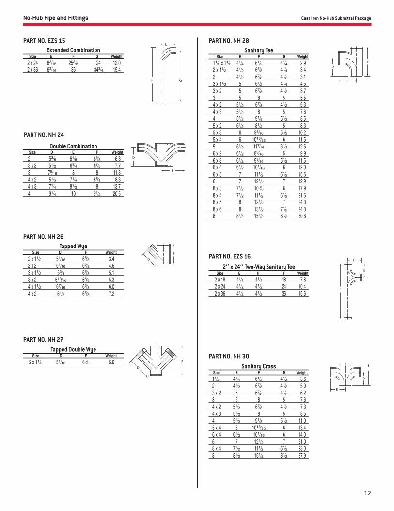
Extended Combination Size E F G Weight
2 x 24 63⁄16 253⁄8 24 12.0 2 x 36 63⁄16 36 343⁄4 15.4
PART NO. EZS 15
Double Combination Size D E F Weight
2 53⁄8 61⁄8 65⁄8 6.3 3 x 2 51⁄2 63⁄4 65⁄8 7.7 3 75⁄16 8 8 11.8 4 x 2 51⁄2 71⁄4 65⁄8 8.3 4 x 3 71⁄4 81⁄2 8 13.7 4 91⁄4 10 91⁄2 20.5
Tapped Wye Size D F Weight
2 x 11⁄2 51⁄16 65⁄8 3.4 2 x 2 51⁄16 65⁄8 4.6 3 x 11⁄2 53⁄4 65⁄8 5.1 3 x 2 513⁄16 65⁄8 5.3 4 x 11⁄2 67⁄16 65⁄8 6.0 4 x 2 61⁄2 65⁄8 7.2
PART NO. NH 24
PART NO. NH 26
Tapped Double Wye Size D F Weight
2 x 11⁄2 51⁄16 65⁄8 5.6
PART NO. NH 27
Sanitary Tee Size E F D Weight
11⁄2 x 11⁄2 41⁄4 61⁄2 41⁄4 2.9 2 x 11⁄2 41⁄2 65⁄8 41⁄4 3.4 2 41⁄2 67⁄8 41⁄2 3.1 3 x 11⁄2 5 61⁄2 41⁄4 4.5 3 x 2 5 67⁄8 41⁄2 3.7 3 5 8 5 5.5 4 x 2 51⁄2 67⁄8 41⁄2 5.3 4 x 3 51⁄2 8 5 7.6 4 51⁄2 91⁄8 51⁄2 8.5 5 x 2 61⁄2 81⁄2 5 8.3 5 x 3 6 95⁄16 51⁄2 10.2 5 x 4 6 1013⁄32 6 11.5 5 61⁄2 117⁄16 61⁄2 12.5 6 x 2 61⁄2 83⁄16 5 9.9 6 x 3 61⁄2 93⁄16 51⁄2 11.5 6 x 4 61⁄2 101⁄16 6 12.0 6 x 5 7 111⁄2 61⁄2 15.6 6 7 121⁄2 7 12.9 8 x 3 71⁄2 103⁄8 6 17.9 8 x 4 71⁄2 111⁄2 61⁄2 21.6 8 x 5 8 121⁄2 7 24.0 8 x 6 8 131⁄2 71⁄2 24.0 8 81⁄2 151⁄2 81⁄2 30.8
PART NO. NH 28
Sanitary Cross Size E F D Weight
11⁄2 41⁄4 61⁄2 41⁄2 3.6 2 41⁄2 67⁄8 41⁄2 5.0 3 x 2 5 67⁄8 41⁄2 6.2 3 5 8 5 7.6 4 x 2 51⁄2 67⁄8 41⁄2 7.3 4 x 3 51⁄2 8 5 8.5 4 51⁄2 91⁄8 51⁄2 11.0 5 x 4 6 1013⁄32 6 13.4 6 x 4 61⁄2 101⁄16 6 14.0 6 7 121⁄2 7 21.0 8 x 4 71⁄2 111⁄2 61⁄2 23.0 8 81⁄2 151⁄2 81⁄2 37.9
2” x 24” Two-Way Sanitary Tee Size E H F Weight
2 x 18 41⁄2 41⁄2 18 7.8 2 x 24 41⁄2 41⁄2 24 10.4 2 x 36 41⁄2 41⁄2 36 15.6
PART NO. EZS 16
PART NO. NH 30
13
No-Hub Pipe and Fittings
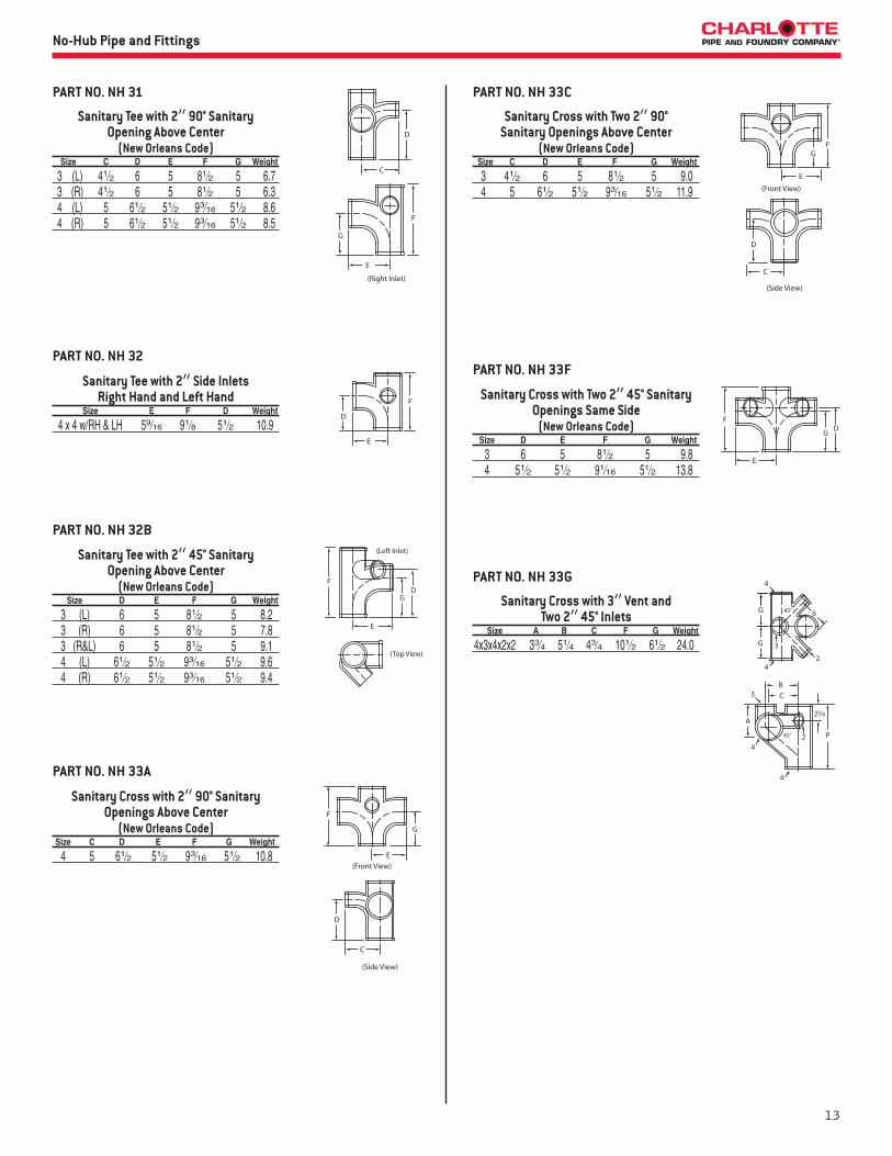
Sanitary Tee with 2” 90° Sanitary Opening Above Center
(New Orleans Code) Size C D E F G Weight
3 (L) 41⁄2 6 5 81⁄2 5 6.7 3 (R) 41⁄2 6 5 81⁄2 5 6.3 4 (L) 5 61⁄2 51⁄2 93⁄16 51⁄2 8.6 4 (R) 5 61⁄2 51⁄2 93⁄16 51⁄2 8.5
Sanitary Tee with 2” Side InletsRight Hand and Left Hand
Size E F D Weight
4 x 4 w/RH & LH 59⁄16 91⁄8 51⁄2 10.9
PART NO. NH 31
PART NO. NH 32
Sanitary Cross with Two 2” 90° Sanitary Openings Above Center
(New Orleans Code) Size C D E F G Weight
3 41⁄2 6 5 81⁄2 5 9.0 4 5 61⁄2 51⁄2 93⁄16 51⁄2 11.9
PART NO. NH 33A
PART NO. NH 33C
Sanitary Cross with 2” 90° Sanitary Openings Above Center
(New Orleans Code) Size C D E F G Weight
4 5 61⁄2 51⁄2 93⁄16 51⁄2 10.8
Sanitary Tee with 2” 45° Sanitary Opening Above Center
(New Orleans Code) Size D E F G Weight
3 (L) 6 5 81⁄2 5 8.2 3 (R) 6 5 81⁄2 5 7.8 3 (R&L) 6 5 81⁄2 5 9.1 4 (L) 61⁄2 51⁄2 93⁄16 51⁄2 9.6 4 (R) 61⁄2 51⁄2 93⁄16 51⁄2 9.4
PART NO. NH 32B
Sanitary Cross with Two 2” 45° Sanitary Openings Same Side
(New Orleans Code) Size D E F G Weight
3 6 5 81⁄2 5 9.8 4 51⁄2 51⁄2 91⁄16 51⁄2 13.8
Sanitary Cross with 3” Vent and Two 2” 45° Inlets
Size A B C F G Weight
4x3x4x2x2 33⁄4 51⁄4 43⁄4 101⁄2 61⁄2 24.0
PART NO. NH 33F
PART NO. NH 33G
14
Cast Iron No-Hub Submittal PackageNo-Hub Pipe and Fittings
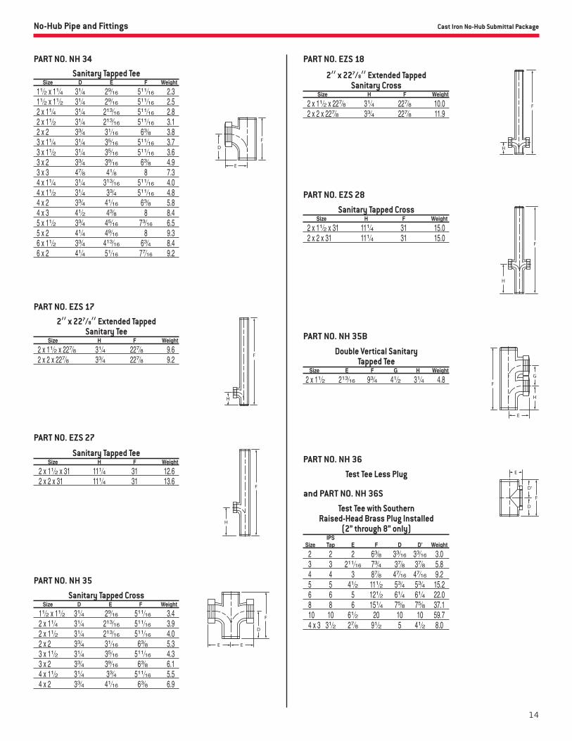
2” x 227⁄8” Extended Tapped Sanitary Tee
Size H F Weight
2 x 11⁄2 x 227⁄8 31⁄4 227⁄8 9.6 2 x 2 x 227⁄8 33⁄4 227⁄8 9.2
PART NO. EZS 17
Sanitary Tapped Cross Size D E F Weight
11⁄2 x 11⁄2 31⁄4 29⁄16 511⁄16 3.4 2 x 11⁄4 31⁄4 213⁄16 511⁄16 3.9 2 x 11⁄2 31⁄4 213⁄16 511⁄16 4.0 2 x 2 33⁄4 31⁄16 63⁄8 5.3 3 x 11⁄2 31⁄4 35⁄16 511⁄16 4.3 3 x 2 33⁄4 39⁄16 63⁄8 6.1 4 x 11⁄2 31⁄4 33⁄4 511⁄16 5.5 4 x 2 33⁄4 41⁄16 63⁄8 6.9
PART NO. NH 35
Sanitary Tapped Tee Size H F Weight
2 x 11⁄2 x 31 111⁄4 31 12.6 2 x 2 x 31 111⁄4 31 13.6
PART NO. EZS 27
2” x 227⁄8” Extended Tapped Sanitary Cross
Size H F Weight
2 x 11⁄2 x 227⁄8 31⁄4 227⁄8 10.0 2 x 2 x 227⁄8 33⁄4 227⁄8 11.9
PART NO. EZS 18
Double Vertical Sanitary Tapped Tee
Size E F G H Weight
2 x 11⁄2 213⁄16 93⁄4 41⁄2 31⁄4 4.8
Sanitary Tapped Cross Size H F Weight
2 x 11⁄2 x 31 111⁄4 31 15.0 2 x 2 x 31 111⁄4 31 15.0
PART NO. EZS 28
PART NO. NH 35B
PART NO. NH 36
Test Tee Less Plug
and PART NO. NH 36S
Test Tee with SouthernRaised-Head Brass Plug Installed
(2” through 8” only) IPS Size Tap E F D D’ Weight
2 2 2 63⁄8 33⁄16 33⁄16 3.0 3 3 211⁄16 73⁄4 37⁄8 37⁄8 5.8 4 4 3 87⁄8 47⁄16 47⁄16 9.2 5 5 41⁄2 111⁄2 53⁄4 53⁄4 15.2 6 6 5 121⁄2 61⁄4 61⁄4 22.0 8 8 6 151⁄4 75⁄8 75⁄8 37.1 10 10 61⁄2 20 10 10 59.7 4 x 3 31⁄2 27⁄8 91⁄2 5 41⁄2 8.0
Sanitary Tapped Tee Size D E F Weight
11⁄2 x 11⁄4 31⁄4 29⁄16 511⁄16 2.3 11⁄2 x 11⁄2 31⁄4 29⁄16 511⁄16 2.5 2 x 11⁄4 31⁄4 213⁄16 511⁄16 2.8 2 x 11⁄2 31⁄4 213⁄16 511⁄16 3.1 2 x 2 33⁄4 31⁄16 63⁄8 3.8 3 x 11⁄4 31⁄4 35⁄16 511⁄16 3.7 3 x 11⁄2 31⁄4 35⁄16 511⁄16 3.6 3 x 2 33⁄4 39⁄16 63⁄8 4.9 3 x 3 47⁄8 41⁄8 8 7.3 4 x 11⁄4 31⁄4 313⁄16 511⁄16 4.0 4 x 11⁄2 31⁄4 33⁄4 511⁄16 4.8 4 x 2 33⁄4 41⁄16 63⁄8 5.8 4 x 3 41⁄2 43⁄8 8 8.4 5 x 11⁄2 33⁄4 45⁄16 73⁄16 6.5 5 x 2 41⁄4 49⁄16 8 9.3 6 x 11⁄2 33⁄4 413⁄16 63⁄4 8.4 6 x 2 41⁄4 51⁄16 77⁄16 9.2
PART NO. NH 34
15
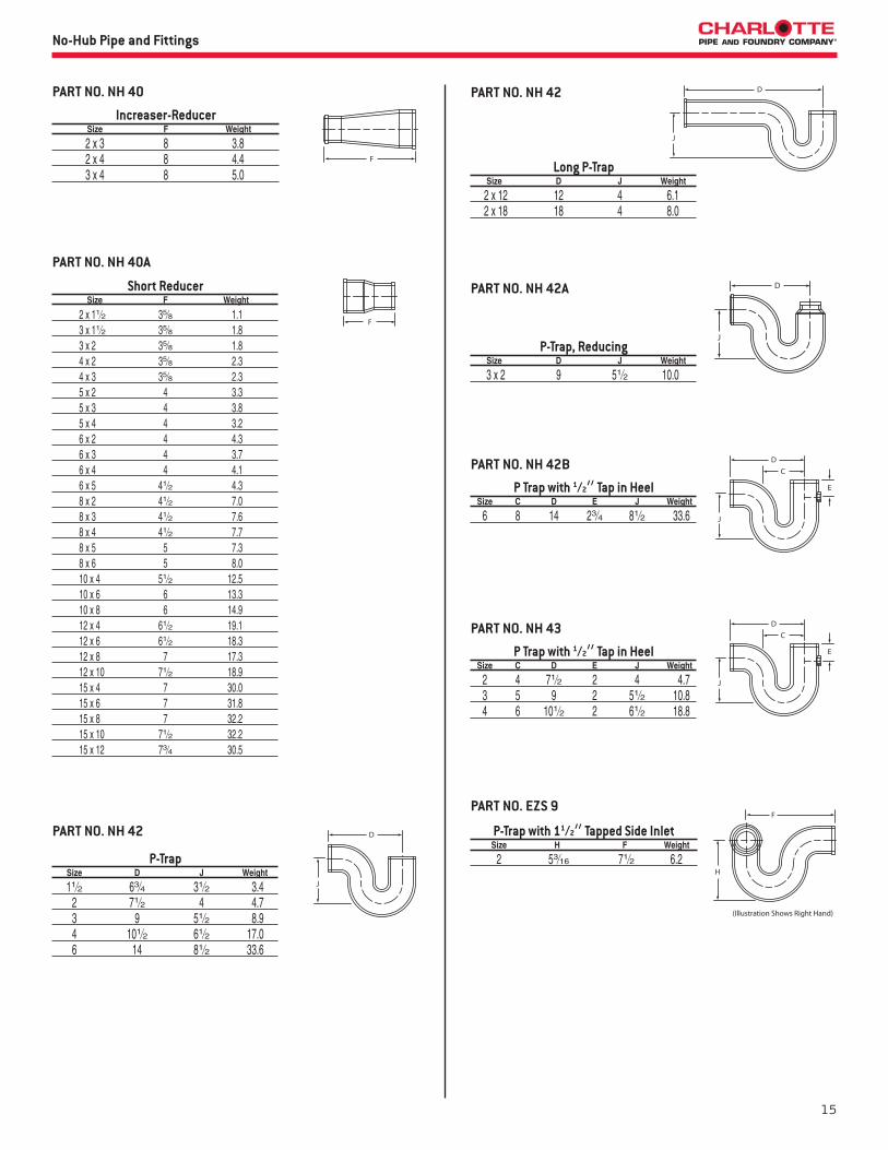
Increaser-Reducer Size F Weight
2 x 3 8 3.8 2 x 4 8 4.4 3 x 4 8 5.0
PART NO. NH 40
No-Hub Pipe and Fittings
Short Reducer Size F Weight
2 x 11⁄2 35⁄8 1.1 3 x 11⁄2 35⁄8 1.8 3 x 2 35⁄8 1.8 4 x 2 35⁄8 2.3 4 x 3 35⁄8 2.3 5 x 2 4 3.3 5 x 3 4 3.8 5 x 4 4 3.2 6 x 2 4 4.3 6 x 3 4 3.7 6 x 4 4 4.1 6 x 5 41⁄2 4.3 8 x 2 41⁄2 7.0 8 x 3 41⁄2 7.6 8 x 4 41⁄2 7.7 8 x 5 5 7.3 8 x 6 5 8.0 10 x 4 51⁄2 12.5 10 x 6 6 13.3 10 x 8 6 14.9 12 x 4 61⁄2 19.1 12 x 6 61⁄2 18.3 12 x 8 7 17.3 12 x 10 71⁄2 18.9 15 x 4 7 30.0 15 x 6 7 31.8 15 x 8 7 32.2 15 x 10 71⁄2 32.2 15 x 12 73⁄4 30.5
PART NO. NH 40A
P-Trap Size D J Weight
11⁄2 63⁄4 31⁄2 3.4 2 71⁄2 4 4.7 3 9 51⁄2 8.9 4 101⁄2 61⁄2 17.0 6 14 81⁄2 33.6
PART NO. NH 42
P Trap with 1⁄2” Tap in Heel Size C D E J Weight
2 4 71⁄2 2 4 4.7 3 5 9 2 51⁄2 10.8 4 6 101⁄2 2 61⁄2 18.8
PART NO. NH 43
Long P-Trap Size D J Weight
2 x 12 12 4 6.1 2 x 18 18 4 8.0
PART NO. NH 42
P-Trap, Reducing Size D J Weight
3 x 2 9 51⁄2 10.0
PART NO. NH 42A
P Trap with 1⁄2” Tap in Heel Size C D E J Weight
6 8 14 23⁄4 81⁄2 33.6
PART NO. NH 42B
P-Trap with 11⁄2” Tapped Side Inlet Size H F Weight
2 53⁄16 71⁄2 6.2
PART NO. EZS 9

16
Cast Iron No-Hub Submittal Package
P-Trap with 2” Side Inlet Size C D J Weight
2 13⁄16 71⁄2 31⁄16 6.4
PART NO. EZS 10
Deep Seal P Trap Size C D J Weight
2 4 71⁄2 7 6.6 3 5 9 7 11.0 4 6 101⁄2 8 18.6
PART NO. NH 44A
P-Trap with Tapped Inlet Size C D J Weight
11⁄2 x 11⁄2 31⁄2 63⁄4 31⁄2 3.0 2 x 11⁄2 4 71⁄2 4 4.5 2 x 2 4 71⁄2 4 5.4
PART NO. NH 44
Running Trap with Double Vent Size C D E F G Weight
4 6 61⁄2 41⁄2 15 101⁄2 21.4
PART NO. NH 45A
Running Trap with Vent Size D E F G Weight
4 61⁄2 41⁄2 15 101⁄2 20.5
PART NO. NH 45
No-Hub Pipe and Fittings
Vented Tub Wye Size G H F Weight
2 91⁄2 51⁄4 15 9.4 2 24 51⁄4 291⁄2 13.7
PART NO. EZS 38
45° Vented Tub Wye Size E F G Weight
2 12 51⁄4 153⁄4 10.1
PART NO. EZS 13
Vented Tub WyeRight Hand
Size G H F Weight
2 91⁄2 33⁄4 15 9.0
PART NO. EZS 38 R
Vented Tub WyeLeft Hand
Size G H F Weight
2 91⁄2 33⁄4 15 10.0
PART NO. EZS 38 L
Tapped Adapters IPS Size F Tapping Weight
11⁄2 x 11⁄2 25⁄8 11⁄2 1.3 2 x 11⁄4 23⁄16 11⁄4 1.0 2 x 11⁄2 23⁄16 11⁄2 0.9 2 x 2 25⁄8 2 1.7 3 x 2 23⁄16 2 1.0
PART NO. NH 48
17
No-Hub Pipe and Fittings
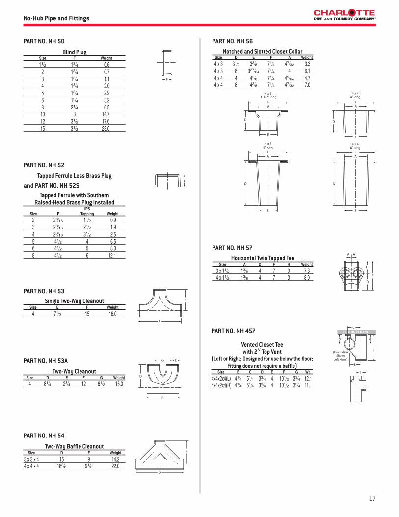
Two-Way Cleanout Size D E F G Weight
4 81⁄4 23⁄4 12 61⁄2 15.0
PART NO. NH 53A
Single Two-Way Cleanout Size E F Weight
4 71⁄2 15 16.0
PART NO. NH 53
Tapped Ferrule Less Brass Plug
PART NO. NH 52
Blind Plug Size F Weight
11⁄2 13⁄4 0.6 2 13⁄4 0.7 3 13⁄4 1.1 4 13⁄4 2.0 5 13⁄4 2.9 6 13⁄4 3.2 8 21⁄4 6.5 10 3 14.7 12 31⁄2 17.6 15 31⁄2 28.0
PART NO. NH 50
and PART NO. NH 52STapped Ferrule with Southern
Raised-Head Brass Plug Installed IPS Size F Tapping Weight
2 23⁄16 11⁄2 0.9 3 23⁄16 21⁄2 1.9 4 23⁄16 31⁄2 2.5 5 41⁄2 4 6.5 6 41⁄2 5 8.0 8 41⁄2 6 12.1
Two-Way Baffle Cleanout Size D F Weight
3 x 3 x 4 15 9 14.2 4 x 4 x 4 183⁄8 91⁄2 22.0
PART NO. NH 54
H
D
F
Horizontal Twin Tapped Tee Size A D F H Weight
3 x 11⁄2 13⁄8 4 7 3 7.3 4 x 11⁄2 13⁄8 4 7 3 8.0
PART NO. NH 57
Notched and Slotted Closet Collar Size D E F A Weight
4 x 3 31⁄2 33⁄8 71⁄4 47⁄32 3.3 4 x 3 8 327⁄64 71⁄4 4 6.1 4 x 4 4 43⁄8 71⁄4 49⁄64 4.7 4 x 4 8 43⁄8 71⁄4 47⁄32 7.0
PART NO. NH 56
Vented Closet Teewith 2” Top Vent
(Left or Right; Designed for use below the floor; Fitting does not require a baffle)
Size B C D E F G Wt.
4x4x2x4(L) 41⁄4 51⁄4 33⁄4 4 101⁄2 33⁄4 12.14x4x2x4(R) 41⁄4 51⁄4 33⁄4 4 101⁄2 33⁄4 11.
PART NO. NH 457

18
Cast Iron No-Hub Submittal PackageNo-Hub Pipe and Fittings
Vented Closet Cross with 2” Top Vent and 2” Side Opening
(Designed for use below the floor;Fitting has a baffle)
Size A B C D E F G Wt.
4x4x2x2x4x4 81⁄8 41⁄4 51⁄4 71⁄2 4 101⁄2 33⁄4 15.6
PART NO. NH 464
Vented Closet Cross with 2” Top Vent(Designed for use below the floor;
Fitting has a baffle) Size B C D E F G Wt
4x4x2x4x4 41⁄4 51⁄4 33⁄4 4 101⁄2 33⁄4 15.0
PART NO. NH 463
Vented Closet Teewith 2” Top Vent and 2” Side Opening
(Left or Right; Designed for use below the floor;Fitting does not require a baffle)
Size A B C D E F G Wt.
4x4x2x2x4(L) 81⁄8 41⁄4 51⁄4 71⁄2 4 101⁄2 33⁄4 12.34x4x2x2x4(R) 81⁄8 41⁄4 51⁄4 71⁄2 4 101⁄2 33⁄4 12.2
PART NO. NH 458 PART NO. NH 502
4” No Hub Prison Fitting with 2” Top Vent(Designed for use above the floor; Baffle helps prevent
passage of contraband between cells) Part No. Size UPC# 611942- A C F G Weight
NH 502 4 Less Tap 00639 8 5 1⁄4 12 8 20.3 NH 502 4 With Tap 00640 8 5 1⁄4 12 8 20.8 NH 502 4x3 Less Tap 11119 8 5 1⁄4 12 8 23.4 NH 502 4x3 With Tap 11120 8 5 1⁄4 12 8 23.4
PART NO. EZS 50*
10” Closet Fittings with 2” Inlet(Double, Left Hand or Right Hand; Designed for use below the floor;
Fitting does not have a baffle) Part No. Size UPC# 611942- A B C D F Weight
EZS 50D*** 4 04484 103⁄4 61⁄2 33⁄4 4 41⁄2 15.0 EZS 50L 4 04476 103⁄4 61⁄2 33⁄4 4 41⁄2 12.3 EZS 50R 4 04477 103⁄4 61⁄2 33⁄4 4 41⁄2 12.2
* When ordering please specify Double, Left or Right.*** Double closet fitting does not have a baffle.
19
No-Hub Pipe and Fittings
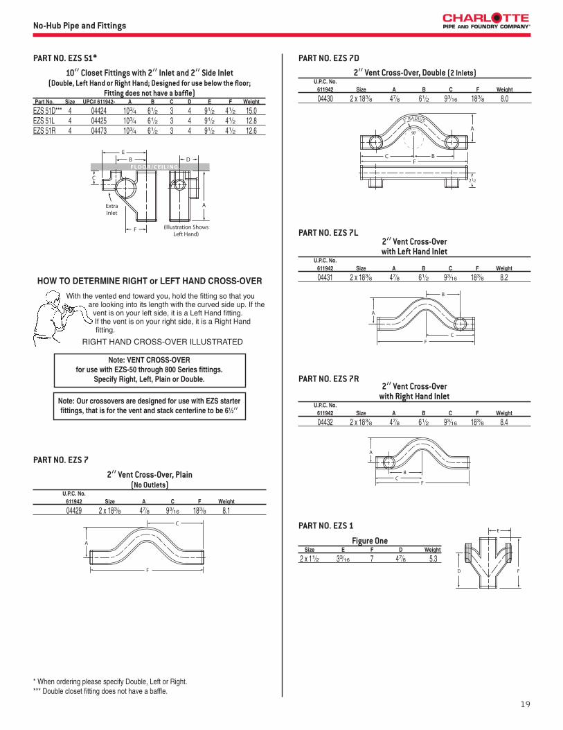
10” Closet Fittings with 2” Inlet and 2” Side Inlet(Double, Left Hand or Right Hand; Designed for use below the floor;
Fitting does not have a baffle) Part No. Size UPC# 611942- A B C D E F Weight
EZS 51D*** 4 04424 103⁄4 61⁄2 3 4 91⁄2 41⁄2 15.0EZS 51L 4 04425 103⁄4 61⁄2 3 4 91⁄2 41⁄2 12.8 EZS 51R 4 04473 103⁄4 61⁄2 3 4 91⁄2 41⁄2 12.6
PART NO. EZS 51*
* When ordering please specify Double, Left or Right.*** Double closet fitting does not have a baffle.
RIGHT HAND CROSS-OVER ILLUSTRATED
With the vented end toward you, hold the fitting so that you are looking into its length with the curved side up. If the
vent is on your left side, it is a Left Hand fitting. If the vent is on your right side, it is a Right Hand fitting.
HOW TO DETERMINE RIGHT or LEFT HAND CROSS-OVER
Note: Our crossovers are designed for use with EZS starter fittings, that is for the vent and stack centerline to be 61⁄2”
2” Vent Cross-Over, Plain (No Outlets)
U.P.C. No. 611942 Size A C F Weight
04429 2 x 183⁄8 47⁄8 93⁄16 183⁄8 8.1
PART NO. EZS 7
Note: VENT CROSS-OVER for use with EZS-50 through 800 Series fittings.
Specify Right, Left, Plain or Double.
2” Vent Cross-Over, Double (2 Inlets) U.P.C. No. 611942 Size A B C F Weight
04430 2 x 183⁄8 47⁄8 61⁄2 93⁄16 183⁄8 8.0
PART NO. EZS 7D
2” Vent Cross-Over with Left Hand Inlet
U.P.C. No. 611942 Size A B C F Weight
04431 2 x 183⁄8 47⁄8 61⁄2 93⁄16 183⁄8 8.2
PART NO. EZS 7L
Figure One Size E F D Weight
2 x 11⁄2 33⁄16 7 47⁄8 5.3
PART NO. EZS 1
2” Vent Cross-Over with Right Hand Inlet
U.P.C. No. 611942 Size A B C F Weight
04432 2 x 183⁄8 47⁄8 61⁄2 93⁄16 183⁄8 8.4
PART NO. EZS 7R
20
Cast Iron No-Hub Submittal PackageNo-Hub Pipe and Fittings
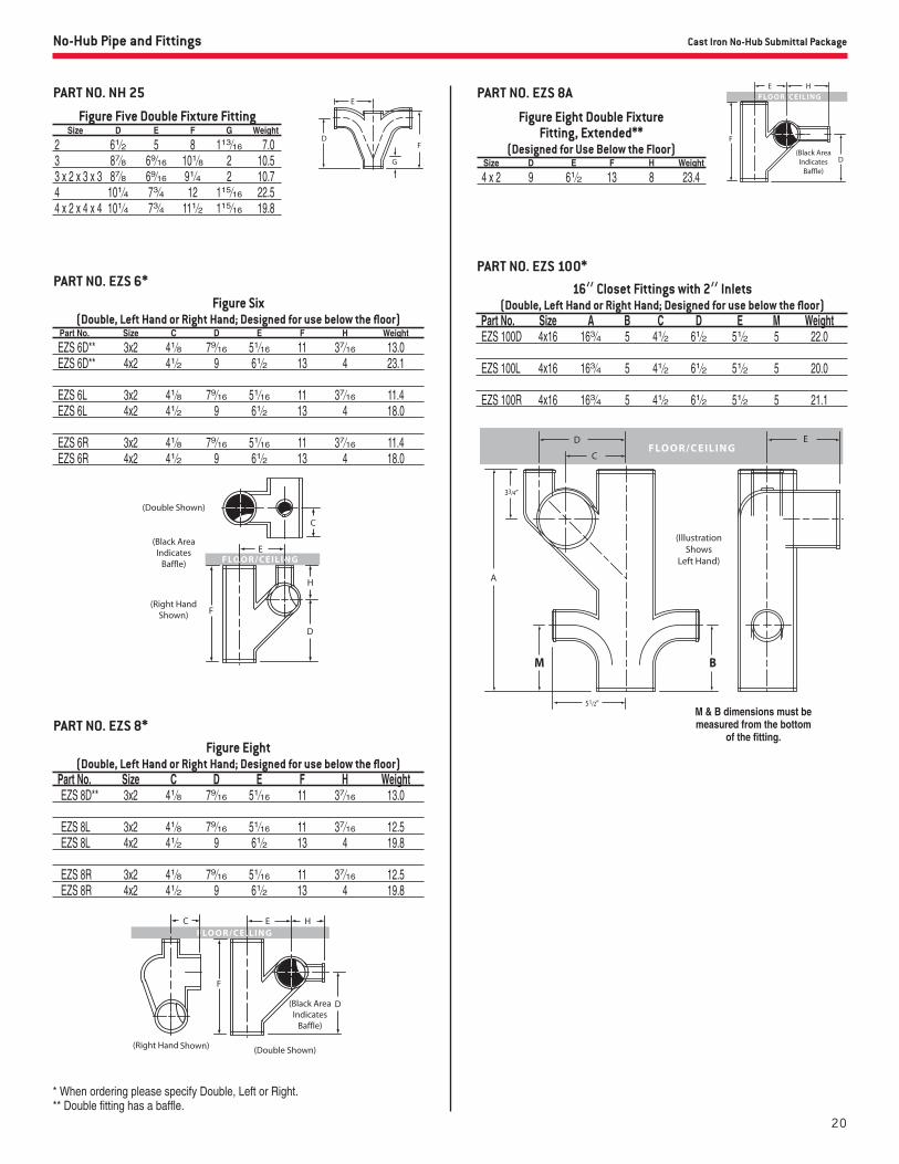
Figure Five Double Fixture Fitting Size D E F G Weight
2 61⁄2 5 8 113⁄16 7.0 3 87⁄8 69⁄16 101⁄8 2 10.5 3 x 2 x 3 x 3 87⁄8 69⁄16 91⁄4 2 10.7 4 101⁄4 73⁄4 12 115⁄16 22.5 4 x 2 x 4 x 4 101⁄4 73⁄4 111⁄2 115⁄16 19.8
PART NO. NH 25
PART NO. EZS 6*Figure Six
(Double, Left Hand or Right Hand; Designed for use below the floor) Part No. Size C D E F H Weight
EZS 6D** 3x2 41⁄8 79⁄16 51⁄16 11 37⁄16 13.0 EZS 6D** 4x2 41⁄2 9 61⁄2 13 4 23.1
EZS 6L 3x2 41⁄8 79⁄16 51⁄16 11 37⁄16 11.4 EZS 6L 4x2 41⁄2 9 61⁄2 13 4 18.0
EZS 6R 3x2 41⁄8 79⁄16 51⁄16 11 37⁄16 11.4 EZS 6R 4x2 41⁄2 9 61⁄2 13 4 18.0
PART NO. EZS 100*
16” Closet Fittings with 2” Inlets(Double, Left Hand or Right Hand; Designed for use below the floor)
Part No. Size A B C D E M Weight EZS 100D 4x16 163⁄4 5 41⁄2 61⁄2 51⁄2 5 22.0
EZS 100L 4x16 163⁄4 5 41⁄2 61⁄2 51⁄2 5 20.0
EZS 100R 4x16 163⁄4 5 41⁄2 61⁄2 51⁄2 5 21.1
M & B dimensions must be measured from the bottom
of the fitting.
* When ordering please specify Double, Left or Right.** Double fitting has a baffle.
Figure Eight Double Fixture Fitting, Extended**
(Designed for Use Below the Floor) Size D E F H Weight
4 x 2 9 61⁄2 13 8 23.4
PART NO. EZS 8A
PART NO. EZS 8*Figure Eight
(Double, Left Hand or Right Hand; Designed for use below the floor) Part No. Size C D E F H Weight EZS 8D** 3x2 41⁄8 79⁄16 51⁄16 11 37⁄16 13.0
EZS 8L 3x2 41⁄8 79⁄16 51⁄16 11 37⁄16 12.5 EZS 8L 4x2 41⁄2 9 61⁄2 13 4 19.8
EZS 8R 3x2 41⁄8 79⁄16 51⁄16 11 37⁄16 12.5 EZS 8R 4x2 41⁄2 9 61⁄2 13 4 19.8

21
No-Hub Pipe and Fittings
PART NO. EZS 400*
* When ordering please specify Double, Left or Right.** Double starter fittings have a baffle.
30” Closet Fittings with 2” Inlet(Double, Left Hand or Right Hand; Designed for use in the floor)
Part No. Size A B C D E M Weight EZS 400L 4x30 30 0 41⁄2 61⁄2 51⁄2 0 34.0 EZS 400L 4x30 30 61⁄2 41⁄2 61⁄2 51⁄2 0 34.2 EZS 400L 4x30 30 12 41⁄2 61⁄2 51⁄2 0 37.8 EZS 400L 4x30 30 261⁄2 41⁄2 61⁄2 51⁄2 0 34.3 EZS 400L 4x30 30 0 41⁄2 61⁄2 51⁄2 4 34.0 EZS 400L 4x30 30 261⁄2 41⁄2 61⁄2 51⁄2 4 34.0 EZS 400L 4x30 30 0 41⁄2 61⁄2 51⁄2 61⁄2 33.1 EZS 400L 4x30 30 61⁄2 41⁄2 61⁄2 51⁄2 61⁄2 34.0 EZS 400L 4x30 30 261⁄2 41⁄2 61⁄2 51⁄2 61⁄2 36.8 EZS 400L 4x30 30 0 41⁄2 61⁄2 51⁄2 12 31.0 EZS 400L 4x30 30 261⁄2 41⁄2 61⁄2 51⁄2 12 30.0
EZS 400R 4x30 30 0 41⁄2 61⁄2 51⁄2 0 32.9 EZS 400R 4x30 30 61⁄2 41⁄2 61⁄2 51⁄2 0 34.5 EZS 400R 4x30 30 12 41⁄2 61⁄2 51⁄2 0 37.1 EZS 400R 4x30 30 261⁄2 41⁄2 61⁄2 51⁄2 0 33.8 EZS 400R 4x30 30 0 41⁄2 61⁄2 51⁄2 4 34.0 EZS 400R 4x30 30 261⁄2 41⁄2 61⁄2 51⁄2 4 28.9 EZS 400R 4x30 30 0 41⁄2 61⁄2 51⁄2 61⁄2 33.9 EZS 400R 4x30 30 61⁄2 41⁄2 61⁄2 51⁄2 61⁄2 35.4 EZS 400R 4x30 30 261⁄2 41⁄2 61⁄2 51⁄2 61⁄2 35.4 EZS 400R 4x30 30 0 41⁄2 61⁄2 51⁄2 12 31.0 EZS 400R 4x30 30 261⁄2 41⁄2 61⁄2 51⁄2 12 28.5
EZS 400D 4x30 30 0 41⁄2 61⁄2 51⁄2 0 29.3 EZS 400D 4x30 30 61⁄2 41⁄2 61⁄2 51⁄2 0 36.4 EZS 400D 4x30 30 12 41⁄2 61⁄2 51⁄2 0 39.6 EZS 400D 4x30 30 0 41⁄2 61⁄2 51⁄2 4 38.0 EZS 400D 4x30 30 0 41⁄2 61⁄2 51⁄2 61⁄2 35.6 EZS 400D 4x30 30 261⁄2 41⁄2 61⁄2 51⁄2 61⁄2 38.9 EZS 400D 4x30 30 0 41⁄2 61⁄2 51⁄2 12 35.7 EZS 400D 4x30 30 261⁄2 41⁄2 61⁄2 51⁄2 12 38.0
A & B Dimensions must be measured from the top
of the fitting.
Threaded Starter Fitting with or without No-Hub Inlets(Double, Left Hand or Right Hand; Designed for use above the floor with
back-outlet water closets; Double Starter fittings have a baffle) Part No. Size A B C D E Weight EZS 700D** 4x28 0 0 51⁄2 28 61⁄2 40.0 EZS 700D** 4x28 0 81⁄2 51⁄2 28 61⁄2 42.0 EZS 700D** 4x28 231⁄2 81⁄2 51⁄2 28 61⁄2 42.0
EZS 700L 4x28 0 0 51⁄2 28 61⁄2 34.6 EZS 700L 4x28 0 81⁄2 51⁄2 28 61⁄2 35.7 EZS 700L 4x28 14 81⁄2 51⁄2 28 61⁄2 36.3 EZS 700L 4x28 231⁄2 81⁄2 51⁄2 28 61⁄2 32.0
EZS 700R 4x28 0 0 51⁄2 28 61⁄2 30.0 EZS 700R 4x28 0 81⁄2 51⁄2 28 61⁄2 34.0 EZS 700R 4x28 14 81⁄2 51⁄2 28 61⁄2 35.3 EZS 700R 4x28 231⁄2 81⁄2 51⁄2 28 61⁄2 32.0
PART NO. EZS 700*
2” inlets available
FLOOR/CEILING
Note: Trim package not included in price of fitting “O” dimension denotes the absence of the designated inlet.

22
Cast Iron No-Hub Submittal PackageNo-Hub Pipe and Fittings
Note: Trim package not included in price of fitting “O” dimension denotes the absence of the designated inlet.
A & B Dimensions must be measured from the top
of the fitting.
Threaded Starter Fitting with or without No-Hub Inlets(Double, Left Hand or Right Hand; Designed for use above the floor with
back-outlet water closets; Double starter fittings have a baffle) Part No. Size A B C D E Weight EZS 800D** 4x28 16 0 51⁄2 28 61⁄2 42.0 EZS 800D** 4x28 16 81⁄2 51⁄2 28 61⁄2 42.0
EZS 800L 4x28 16 0 51⁄2 28 61⁄2 35.4 EZS 800L 4x28 16 81⁄2 51⁄2 28 61⁄2 36.3
EZS 800R 4x28 16 0 51⁄2 28 61⁄2 35.6 EZS 800R 4x28 16 81⁄2 51⁄2 28 61⁄2 35.3
PART NO. EZS 800*
A & B Dimensions must be measured from the top
of the fitting.
No-Hub Starter Fitting with or without 2” No-Hub Inlets(Double, Left Hand or Right Hand; Designed for use above the floor with
back-outlet water closets; Double starter fittings have a baffle) Part No. Size A B C D E Weight EZS 710D** 4x28 0 0 51⁄2 28 4 43.0 EZS 710D** 4x28 0 81⁄2 51⁄2 28 4 43.0 EZS 710D** 4x28 231⁄2 81⁄2 51⁄2 28 4 43.0
EZS 710L 4x28 0 0 51⁄2 28 4 36.6 EZS 710L 4x28 0 81⁄2 51⁄2 28 4 36.6 EZS 710L 4x28 14 81⁄2 51⁄2 28 4 36.6 EZS 710L 4x28 231⁄2 81⁄2 51⁄2 28 4 36.6
EZS 710R 4x28 0 0 51⁄2 28 4 36.6 EZS 710R 4x28 0 81⁄2 51⁄2 28 4 36.6 EZS 710R 4x28 14 81⁄2 51⁄2 28 4 36.6 EZS 710R 4x28 231⁄2 81⁄2 51⁄2 28 4 36.6
PART NO. EZS 710*
2” inlets available
(IllustrationShows Left Hand)
(IllustrationShows Double)
Note: Not designed for use with trim package “O” dimension denotes the absence of the designated inlet.
* When ordering please specify Double, Left or Right.** Double starter fittings have a baffle.
2” inlets available
FLOOR/CEILING(Illustration
Shows Right Hand)
(IllustrationShows Double)
2” inlets available

23
No-Hub Pipe and Fittings
A & B Dimensions must be measured from the top
of the fitting.
No-Hub Starter Fitting with or without 2” No-Hub Inlets(Double, Left Hand or Right Hand; Designed for use above the floor with
back-outlet water closets; Double starter fittings have a baffle) Part No. Size A B C D E Weight EZS 810D** 4x28 16 0 51⁄2 28 61⁄2 43.0 EZS 810D** 4x28 16 81⁄2 51⁄2 28 61⁄2 43.0
EZS 810L 4x28 16 0 51⁄2 28 61⁄2 36.6 EZS 810L 4x28 16 81⁄2 51⁄2 28 61⁄2 36.6
EZS 810R 4x28 16 0 51⁄2 28 61⁄2 36.6 EZS 810R 4x28 16 81⁄2 51⁄2 28 61⁄2 36.6
PART NO. EZS 810*
2” inlets available
(IllustrationShows Right Hand)
(IllustrationShows Double)
Note: Not designed for use with trim package “O” dimension denotes the absence of the designated inlet.
MOUNTING HARDWARE
PART NO. EZS 22 Trim Package, Support Frame Assembly
PART NO. EZS 23 Trim Package, Floor-Mounted Back-Outlet Assembly(Note: Not to be used with PART NO. EZS 22 Support Frame Assembly)
1—FRAME1—LEFT LEG1—RIGHT LEG1—SUPPORT LEG (used for single only)5—1⁄2” x 11⁄4” BOLTS5—1⁄2” FLAT WASHERS
PART NO. EZS 24 Trim Package, Wall-Hung Back-Outlet Assembly(Note: To be used with PART NO. EZS 22 Support Frame Assembly)
1—4” PVC Sch. 80 NIPPLE with TEST CAP1—BOWL GASKET2—5⁄16” x 12” RODS2—5⁄16” HEX NUTS2—5⁄16” FLAT WASHERS2—5⁄16” CAP NUTS
Exploded View of Support Assembly Hardware
1—4” PVC Sch. 80 NIPPLE with TEST CAP1—BOWL GASKET4—5⁄8” x 12” RODS4—5⁄8” CHROME CAP NUTS8—5⁄8” JAM NUTS4—5⁄8” FLAT WASHERS4—5⁄8” FIBER WASHERS3—3⁄8” x 11⁄2” BOLTS FOR FACEPLATE3—3⁄8” FLAT WASHERS4—5⁄8” STAR WASHERS EZS 22 and EZS 24 Assemblies Illustrated
A B C D
20 9 71⁄2 4
* When ordering please specify Double, Left or Right.** Double starter fittings have a baffle.
24
Cast Iron No-Hub Submittal PackageNo-Hub Pipe and Fittings
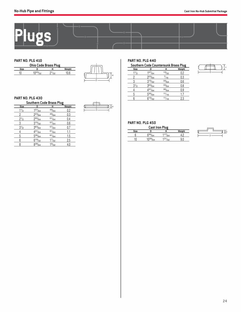
Ohio Code Brass Plug Size D H Weight
10 1023⁄32 21⁄32 10.6
PART NO. PLG 410
Southern Code Brass Plug Size D H Weight
11⁄2 157⁄64 49⁄64 0.2 2 223⁄64 49⁄64 0.3 21⁄2 255⁄64 51⁄64 0.4 3 315⁄32 57⁄64 0.6 31⁄2 363⁄64 57⁄64 0.7 4 431⁄64 61⁄64 1.1 5 535⁄64 61⁄64 1.5 6 619⁄32 17⁄32 2.5 8 839⁄64 19⁄32 4.0
PART NO. PLG 430
Southern Code Countersunk Brass Plug Size D H Weight
11⁄2 157⁄64 13⁄32 0.2 2 223⁄64 7⁄16 0.3 3 315⁄32 33⁄64 0.6 31⁄2 363⁄64 33⁄64 0.8 4 431⁄64 35⁄64 0.9 5 535⁄64 11⁄16 1.7 6 619⁄32 11⁄16 2.3
PART NO. PLG 440
Cast Iron Plug Size D H Weight
6 635⁄64 117⁄64 4.2 10 1039⁄64 131⁄32 9.0
PART NO. PLG 450
Plugs
25FO-SUB-CI-NHC (1115)
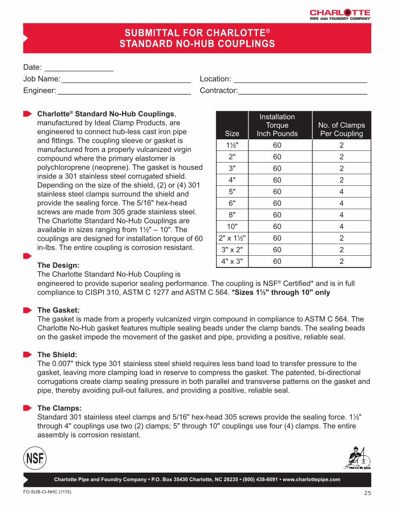
Date: ________________Job Name: ______________________________ Location: _______________________________Engineer: _______________________________ Contractor: ______________________________
Charlotte® Standard No-Hub Couplings, manufactured by Ideal Clamp Products, are engineered to connect hub-less cast iron pipe and fittings. The coupling sleeve or gasket is manufactured from a properly vulcanized virgin compound where the primary elastomer is polychloroprene (neoprene). The gasket is housed inside a 301 stainless steel corrugated shield. Depending on the size of the shield, (2) or (4) 301 stainless steel clamps surround the shield and provide the sealing force. The 5/16" hex-head screws are made from 305 grade stainless steel. The Charlotte Standard No-Hub Couplings are available in sizes ranging from 11⁄2" – 10". The couplings are designed for installation torque of 60 in-lbs. The entire coupling is corrosion resistant.
The Design: The Charlotte Standard No-Hub Coupling is
SUBMITTAL FOR CHARLOTTE® STANDARD NO-HUB COUPLINGS
engineered to provide superior sealing performance. The coupling is NSF® Certified* and is in full compliance to CISPI 310, ASTM C 1277 and ASTM C 564. *Sizes 11⁄2" through 10" only
The Gasket:The gasket is made from a properly vulcanized virgin compound in compliance to ASTM C 564. The Charlotte No-Hub gasket features multiple sealing beads under the clamp bands. The sealing beads on the gasket impede the movement of the gasket and pipe, providing a positive, reliable seal.
The Shield:The 0.007" thick type 301 stainless steel shield requires less band load to transfer pressure to the gasket, leaving more clamping load in reserve to compress the gasket. The patented, bi-directional corrugations create clamp sealing pressure in both parallel and transverse patterns on the gasket and pipe, thereby avoiding pull-out failures, and providing a positive, reliable seal.
The Clamps:Standard 301 stainless steel clamps and 5/16" hex-head 305 screws provide the sealing force. 11⁄2" through 4" couplings use two (2) clamps; 5" through 10" couplings use four (4) clamps. The entire assembly is corrosion resistant.
Installation Torque No. of Clamps Size Inch Pounds Per Coupling 11⁄2" 60 2 2" 60 2 3" 60 2 4" 60 2 5" 60 4 6" 60 4 8" 60 4 10" 60 4 2" x 11⁄2" 60 2 3" x 2" 60 2 4" x 3" 60 2
Charlotte Pipe and Foundry Company • P.O. Box 35430 Charlotte, NC 28235 • (800) 438-6091 • www.charlottepipe.com
26
Cast Iron No-Hub Submittal Package
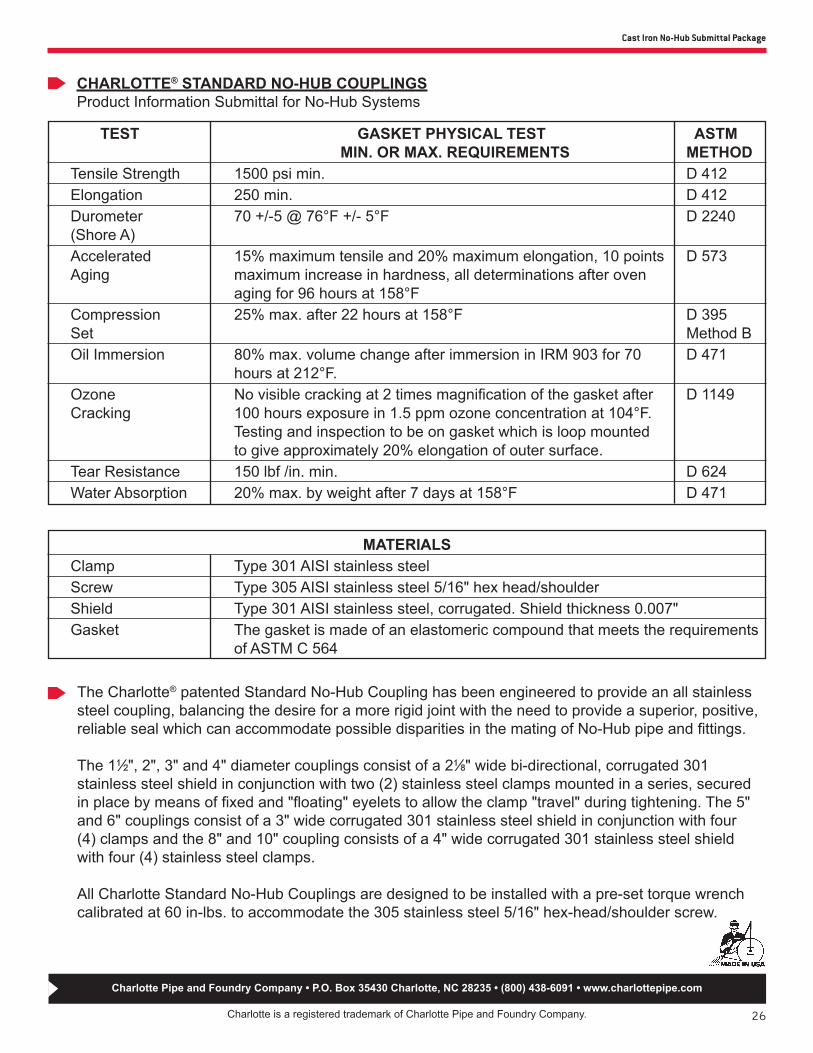
CHARLOTTE® STANDARD NO-HUB COUPLINGSProduct Information Submittal for No-Hub Systems
Charlotte is a registered trademark of Charlotte Pipe and Foundry Company.
Charlotte Pipe and Foundry Company • P.O. Box 35430 Charlotte, NC 28235 • (800) 438-6091 • www.charlottepipe.com
TEST GASKET PHYSICAL TEST ASTM MIN. OR MAX. REQUIREMENTS METHOD Tensile Strength 1500 psi min. D 412 Elongation 250 min. D 412 Durometer 70 +/-5 @ 76°F +/- 5°F D 2240 (Shore A) Accelerated 15% maximum tensile and 20% maximum elongation, 10 points D 573 Aging maximum increase in hardness, all determinations after oven aging for 96 hours at 158°F Compression 25% max. after 22 hours at 158°F D 395 Set Method B Oil Immersion 80% max. volume change after immersion in IRM 903 for 70 D 471 hours at 212°F. Ozone No visible cracking at 2 times magnification of the gasket after D 1149 Cracking 100 hours exposure in 1.5 ppm ozone concentration at 104°F. Testing and inspection to be on gasket which is loop mounted to give approximately 20% elongation of outer surface. Tear Resistance 150 lbf /in. min. D 624 Water Absorption 20% max. by weight after 7 days at 158°F D 471
The Charlotte® patented Standard No-Hub Coupling has been engineered to provide an all stainless steel coupling, balancing the desire for a more rigid joint with the need to provide a superior, positive, reliable seal which can accommodate possible disparities in the mating of No-Hub pipe and fittings.
The 11⁄2", 2", 3" and 4" diameter couplings consist of a 21⁄8" wide bi-directional, corrugated 301 stainless steel shield in conjunction with two (2) stainless steel clamps mounted in a series, securedin place by means of fixed and "floating" eyelets to allow the clamp "travel" during tightening. The 5"and 6" couplings consist of a 3" wide corrugated 301 stainless steel shield in conjunction with four(4) clamps and the 8" and 10" coupling consists of a 4" wide corrugated 301 stainless steel shieldwith four (4) stainless steel clamps.
All Charlotte Standard No-Hub Couplings are designed to be installed with a pre-set torque wrench calibrated at 60 in-lbs. to accommodate the 305 stainless steel 5/16" hex-head/shoulder screw.
MATERIALS Clamp Type 301 AISI stainless steel Screw Type 305 AISI stainless steel 5/16" hex head/shoulder Shield Type 301 AISI stainless steel, corrugated. Shield thickness 0.007" Gasket The gasket is made of an elastomeric compound that meets the requirements of ASTM C 564

27FO-SUB-CI-MDC (1115)
Date: ________________Job Name: ______________________________ Location: _______________________________Engineer: _______________________________ Contractor: ______________________________
Charlotte® Heavy-Duty "MD" (yellow shield)No-Hub Couplings, manufactured by Ideal Clamp Products, are engineered to connect No-Hub cast iron pipe in applications replacing the less-efficient hub & spigot material. Coupling consists of an elastomeric compound gasket (ASTM C 564) housed inside a 304 stainless steel corrugated shield. Depending on the size of the shield, (4) or (6) 304 stainless steel clamps surround the shield and provide the sealing force. The 5/16" hex-head screws are made from 305 stainless steel. The Charlotte patented Heavy-Duty "MD" No-Hub Couplings are available in sizes ranging from 11⁄2" – 10". The couplings are designed to be torqued to 80 in-lbs. The entire coupling is corrosion resistant.
SUBMITTAL FOR CHARLOTTE® HEAVY-DUTY "MD" NO-HUB COUPLINGS
Conforms to ASTM C 1540.
The Design: The Charlotte Heavy-Duty "MD" No-Hub Couplings are engineered to provide all the extra holding power of a Heavy-Duty coupling without all the extra cost. Conforms to ASTM C 1540.
The Gasket:Made from high-quality elastomeric compound (ASTM C 564), the Charlotte No-Hub gasket features a pattern of multiple thick sealing sectors and adjacent groove sectors laterally spaced. When the clamps are tightened, this pattern permits the clamping bands and the shield to form a restriction impeding the movement of the shield relative to the gasket.
The Shield:0.008" thick type 304 stainless steel yellow shield requires less band load to transfer pressure to the gasket, leaving more clamping load in reserve to compress the gasket. The patented, bi-directional corrugations create clamp sealing pressure in both parallel and transverse patterns on the gasket and pipe, thereby avoiding pull-out failures, and providing a positive, reliable seal.
The Clamps:Heavy-duty 304 stainless steel clamps and 5/16" hex-head 305 screws provide the sealing force. 11⁄2" through 4" couplings use four (4) clamps; 5" through 10" couplings use six (6) clamps. The entire assembly is corrosion resistant.
Installation Torque No. of Clamps Size Inch Pounds Per Coupling 11⁄2" 80 4 2" 80 4 3" 80 4 4" 80 4 5" 80 6 6" 80 6 8" 80 6 10" 80 6
Charlotte Pipe and Foundry Company • P.O. Box 35430 Charlotte, NC 28235 • (800) 438-6091 • www.charlottepipe.com
Heavy-Duty "MD" No-Hub Couplings

28
Cast Iron No-Hub Submittal Package
CHARLOTTE® HEAVY-DUTY "MD" NO-HUB COUPLINGSProduct Information Submittal for No-Hub Systems
Charlotte is a registered trademark of Charlotte Pipe and Foundry Company.
Charlotte Pipe and Foundry Company • P.O. Box 35430 Charlotte, NC 28235 • (800) 438-6091 • www.charlottepipe.com
TEST GASKET PHYSICAL TEST ASTM MIN. OR MAX. REQUIREMENTS METHOD Tensile Strength 1500 psi min. D 412 Elongation 250 min. D 412 Durometer 70 +/-5 @ 76°F +/- 5°F D 2240 (Shore A) Accelerated 15% maximum tensile and 20% maximum elongation, 10 points D 573 Aging maximum increase in hardness, all determinations after oven aging for 96 hours at 158°F Compression 25% max. after 22 hours at 158°F D 395 Set Method B Oil Immersion 80% max. volume change after immersion in IRM 903 for 70 D 471 hours at 212°F. Ozone No visible cracking at 2 times magnification of the gasket after D 1149 Cracking 100 hours exposure in 1.5 ppm ozone concentration at 104°F. Testing and inspection to be on gasket which is loop mounted to give approximately 20% elongation of outer surface. Tear Resistance 150 lbf /in. min. D 624 Water Absorption 20% max. by weight after 7 days at 158°F D 471
The Charlotte® Heavy-Duty "MD" No-Hub Coupling has been engineered to provide a mid-range, all stainless steel coupling, balancing the desire for a more rigid joint with the need to provide a superior, positive seal which can accommodate possible disparities in the mating of No-Hub pipe and fittings. This has been accomplished by manufacturing our coupling with a mid-range corrugated shield of sufficient width to accommodate additional surface-bearing sealing clamps.The additional sealing clamps, when torqued to 80 in-lbs, deliver additional performance benefits. First the overall dimensional thickness of the clamp and shield, in conjunction with the additional width of the coupling, result in a more uniformly rigid joint, with the load being supported at both the outer edge of the coupling and the centerline of the joint. Second, the additional sealing clamps yield increased surface-bearing contact between the coupling and the pipe or fittings, thereby inhibiting joint movement at higher internal pressures not commonly associated with DWV systems.The 11⁄2", 2", 3" and 4" diameter couplings consist of a 3" wide bi-directional, corrugated 304 stainless steel shield in conjunction with four (4) stainless steel clamps mounted in a series, secured in place by means of fixed and "floating" eyelets to allow the clamp "travel" during tightening. The 5", 6" 8" and 10" couplings consist of a 4" corrugated 304 stainless steel shield and six (6) stainless steel clamps.All Charlotte Heavy-Duty "MD" No-Hub Couplings are designed to be installed with a pre-set torque wrench calibrated at 80 in-lbs. accommodates the 305 stainless steel 5/16" hex-head/ shoulder screw.
MATERIALS Clamp Type 304 AISI stainless steel Screw Type 305 AISI stainless steel 5/16" hex head/shoulder Shield Type 304 AISI stainless steel, corrugated. Shield thickness 0.008" Gasket The gasket is made of an elastomeric compound that meets the requirements of ASTM C 564

29FO-SUB-CI-HDC (1117)
Date: ________________Job Name: ______________________________ Location: _______________________________Engineer: _______________________________ Contractor: ______________________________
Charlotte® Heavy-Duty "HD" (green shield) No-Hub Couplings, manufactured by Ideal Clamp Products, are engineered to connect No-Hub cast iron pipe in applications replacing the less-efficient hub & spigot material. The Coupling consists of an elastomeric compound gasket (ASTM C 564) housed inside a 304 stainless steel corrugated shield. Depending on the size of the shield, (4) or (6) 304 stainless steel clamps surround the shield and provide the sealing force. The 3/8" hex-head screws are made from 305 stainless- steel. Charlotte Heavy-Duty "HD" No-Hub Couplings are available in sizes ranging from 11⁄2" – 10". The couplings are designed to be torqued to 80 in-lbs. The entire coupling is corrosion resistant. Conforms to ASTM C 1540.
SUBMITTAL FOR CHARLOTTE® HEAVY-DUTY "HD" NO-HUB COUPLINGS
The Design: Charlotte Heavy-Duty "HD" No-Hub Couplings have been re-engineered to install with 80 in-lbs. of screw torque and boasts an ultimate torque rating exceeding 100 in/lbs. Our patented, extra wide bi-directional shield is now constructed with a heavier gauge stainless steel. The mechanically interlocked 9/16" wide clamps have also been augmented with a heavier gauge stainless steel and a 3/8" hex-head screw. These changes, teamed with our specially beaded gasket, enable our new Heavy-Duty "HD" coupling to exert exceptional hold on the pipe for a positive, reliable seal. Conforms to ASTM C 1540.
The Gasket:Made from high-quality elastomeric compound (ASTM C 564), the Charlotte No-Hub gasket features a pattern of multiple thick sealing sectors and adjacent groove sectors laterally spaced. When the clamps are tightened, this pattern permits the clamping bands and the shield to form a restriction impeding the movement of the shield relative to the gasket.
The Shield:0.008" thick type 304 stainless steel green shield requires less band load to transfer pressure to the gasket, leaving more clamping load in reserve to compress the gasket. The patented, bi-directional corrugations create clamp sealing pressure in both parallel and transverse patterns on the gasket and pipe, thereby avoiding pull-out failures, and providing a positive, reliable seal.
The Clamps:Heavy-duty 304 stainless steel clamps and 3/8" hex-head 305 screws provide the sealing force. 1½" through 4" couplings use four (4) clamps; 5" through 10" couplings use six (6) clamps. The entire assembly is corrosion resistant.
Installation Torque No. of Clamps Size Inch Pounds Per Coupling 11⁄2" 80 4 2" 80 4 3" 80 4 4" 80 4 5" 80 6 6" 80 6 8" 80 6 10" 80 6
Charlotte Pipe and Foundry Company • P.O. Box 35430 Charlotte, NC 28235 • (800) 438-6091 • www.charlottepipe.com
Heavy-Duty "HD" No-Hub Couplings
30
Cast Iron No-Hub Submittal Package
CHARLOTTE® HEAVY-DUTY "HD" NO-HUB COUPLINGSProduct Information Submittal for No-Hub Systems
Charlotte is a registered trademark of Charlotte Pipe and Foundry Company.
Charlotte Pipe and Foundry Company • P.O. Box 35430 Charlotte, NC 28235 • (800) 438-6091 • www.charlottepipe.com
TEST GASKET PHYSICAL TEST ASTM MIN. OR MAX. REQUIREMENTS METHOD Tensile Strength 1500 psi min. D 412 Elongation 250 min. D 412 Durometer 70 +/-5 @ 76°F +/- 5°F D 2240 (Shore A) Accelerated 15% maximum tensile and 20% maximum elongation, 10 points D 573 Aging maximum increase in hardness, all determinations after oven aging for 96 hours at 158°F Compression 25% max. after 22 hours at 158°F D 395 Set Method B Oil Immersion 80% max. volume change after immersion in IRM 903 for 70 D 471 hours at 212°F. Ozone No visible cracking at 2 times magnification of the gasket after D 1149 Cracking 100 hours exposure in 1.5 ppm ozone concentration at 104°F. Testing and inspection to be on gasket which is loop mounted to give approximately 20% elongation of outer surface. Tear Resistance 150 lbf /in. min. D 624 Water Absorption 20% max. by weight after 7 days at 158°F D 471
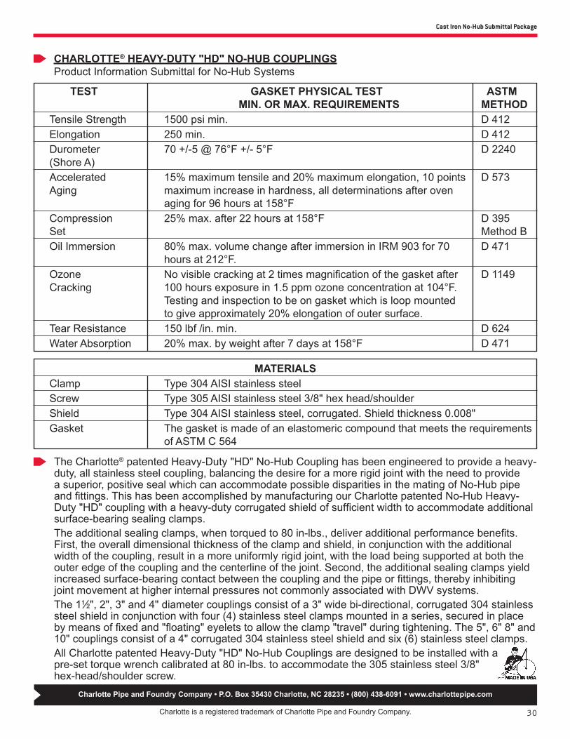
The Charlotte® patented Heavy-Duty "HD" No-Hub Coupling has been engineered to provide a heavy-duty, all stainless steel coupling, balancing the desire for a more rigid joint with the need to provide a superior, positive seal which can accommodate possible disparities in the mating of No-Hub pipe and fittings. This has been accomplished by manufacturing our Charlotte patented No-Hub Heavy-Duty "HD" coupling with a heavy-duty corrugated shield of sufficient width to accommodate additional surface-bearing sealing clamps.The additional sealing clamps, when torqued to 80 in-lbs., deliver additional performance benefits. First, the overall dimensional thickness of the clamp and shield, in conjunction with the additional width of the coupling, result in a more uniformly rigid joint, with the load being supported at both the outer edge of the coupling and the centerline of the joint. Second, the additional sealing clamps yield increased surface-bearing contact between the coupling and the pipe or fittings, thereby inhibiting joint movement at higher internal pressures not commonly associated with DWV systems.The 11⁄2", 2", 3" and 4" diameter couplings consist of a 3" wide bi-directional, corrugated 304 stainless steel shield in conjunction with four (4) stainless steel clamps mounted in a series, secured in place by means of fixed and "floating" eyelets to allow the clamp "travel" during tightening. The 5", 6" 8" and 10" couplings consist of a 4" corrugated 304 stainless steel shield and six (6) stainless steel clamps.All Charlotte patented Heavy-Duty "HD" No-Hub Couplings are designed to be installed with a pre-set torque wrench calibrated at 80 in-lbs. to accommodate the 305 stainless steel 3/8" hex-head/shoulder screw.
MATERIALS Clamp Type 304 AISI stainless steel Screw Type 305 AISI stainless steel 3/8" hex head/shoulder Shield Type 304 AISI stainless steel, corrugated. Shield thickness 0.008" Gasket The gasket is made of an elastomeric compound that meets the requirements of ASTM C 564

31FO-SUB-CI-HDC-LD (1115)
Date: ________________Job Name: ______________________________ Location: _______________________________Engineer: _______________________________ Contractor: ______________________________
Charlotte® Heavy-Duty No-Hub Couplings, manufactured by Ideal Clamp Products, are engineered to connect No-Hub cast iron pipe in applications replacing the less-efficient hub & spigot material. The Couplings consist of an elastomeric compound gasket (ASTM C 564) housed inside a 304 stainless steel corrugated shield. Six (6) 304 stainless steel clamps surround the shield and provide the sealing force. The 3/8" hex-head screws are made from 305 stainless steel. The Couplings are designed for installation torque of 120 in-lbs. The entire coupling is corrosion resistant.
SUBMITTAL FOR CHARLOTTE® 12" AND 15" HEAVY-DUTY NO-HUB COUPLINGS
The Design: Charlotte 12" and 15" Heavy-Duty No-Hub Couplings are engineered to provide superior performance at a very competitive cost. Conforms to ASTM C 1277.
The Gasket:Made from high-quality elastomeric compound (ASTM C 564), the Charlotte No-Hub gasket features a pattern of multiple, thick sealing sectors and adjacent groove sectors laterally spaced. When the clamps are tightened, this pattern permits the clamping bands and the shield to form a restriction impeding the movement of the shield relative to the gasket.
The Shield:0.008" thick type 304 stainless steel shield requires less band load to transfer pressure to the gasket, leaving more clamping load in reserve to compress the gasket. The patented, bi-directional corrugations create clamp sealing pressure in both parallel and transverse patterns on the gasket and pipe, thereby avoiding pull-out failures, and providing a positive, reliable seal. In addition, the shield design adjusts to differences in the circumference and outside diameters of the pipes being joined. This eliminates gasket wrinkling and thereby eliminating leak paths.
The Clamps:Heavy-duty 304 stainless steel clamps and 3/8" hex-head 305 screws provide the sealing force. Both the 12" and the 15" coupling use six (6) 5/8" wide clamps. The entire assembly is corrosion resistant.
12" & 15" Heavy-Duty No-Hub Couplings
Installation Torque No. of Clamps Size Inch Pounds Per Coupling 12" 120 6 15" 120 6
Charlotte Pipe and Foundry Company • P.O. Box 35430 Charlotte, NC 28235 • (800) 438-6091 • www.charlottepipe.com

32
Cast Iron No-Hub Submittal Package
CHARLOTTE® 12" & 15" NO-HUB COUPLINGSProduct Information Submittal for No-Hub Systems
Charlotte is a registered trademark of Charlotte Pipe and Foundry Company.
Charlotte Pipe and Foundry Company • P.O. Box 35430 Charlotte, NC 28235 • (800) 438-6091 • www.charlottepipe.com
TEST GASKET PHYSICAL TEST ASTM MIN. OR MAX. REQUIREMENTS METHOD Tensile Strength 1500 psi min. D 412 Elongation 250 min. D 412 Durometer 70 +/-5 @ 76°F +/- 5°F D 2240 (Shore A) Accelerated 15% maximum tensile and 20% maximum elongation, 10 points D 573 Aging maximum increase in hardness, all determinations after oven aging for 96 hours at 158°F Compression 25% max. after 22 hours at 158°F D 395 Set Method B Oil Immersion 80% max. volume change after immersion in IRM 903 for 70 D 471 hours at 212°F. Ozone No visible cracking at 2 times magnification of the gasket after D 1149 Cracking 100 hours exposure in 1.5 ppm ozone concentration at 104°F. Testing and inspection to be on gasket which is loop mounted to give approximately 20% elongation of outer surface. Tear Resistance 150 lbf /in. min. D 624 Water Absorption 20% max. by weight after 7 days at 158°F D 471
The Charlotte® Heavy-Duty No-Hub Coupling has been engineered to provide an all stainless steel coupling, balancing the desire for a more rigid joint with the need to provide a superior, positive, reliable seal which can accommodate possible disparities in the mating of No-Hub pipe and fittings. This has been accomplished by manufacturing our coupling with our standard corrugated shield of sufficient width to accommodate additional surface-bearing sealing clamps.
The additional sealing clamps, when torqued to 120 in-lbs., deliver additional performance benefits. First, the overall dimensional thickness of the clamp and shield, in conjunction with the additional width of the coupling, result in a more uniformly rigid joint, with the load being supported at both the outer edge of the coupling and the centerline of the joint. Second, the additional sealing clamps yield increased surface-bearing contact between the coupling and the pipe or fittings, thereby inhibiting joint movement at higher internal pressures not commonly associated with DWV systems.
The 12" and 15" diameter couplings consist of a 5 1/2" wide bi-directional, corrugated 304 stainless steel shield in conjunction with six (6) stainless steel clamps mounted in a series, secured in place by means of fixed and "floating" eyelets to allow the clamp "travel" during tightening.
MATERIALS Clamp Type 304 AISI stainless steel Screw Type 305 AISI stainless steel 3/8" hex head/shoulder Shield Type 304 AISI stainless steel, corrugated. Shield thickness 0.008" Gasket The gasket is made of an elastomeric compound that meets the requirements of ASTM C 564

33
Limited Warranty
Charlotte Pipe and Foundry Company® (Charlotte Pipe®) Products are warranted to be free from manufacturing defects and to conform to currently applicable ASTM standards for a period of five (5) years from date of delivery. Buyer’s remedy for breach of this warranty is limited to replacement of, or credit for, the defective product. This warranty excludes any expense for removal or reinstallation of any defective product and any other incidental, consequential, or punitive damages. This limited warranty is the only warranty made by seller and is expressly in lieu of all other warranties, express and implied, including any warranties of merchantability and fitness for a particular purpose. No statement, conduct or description by Charlotte Pipe or its representative, in addition to or beyond this Limited Warranty, shall constitute a warranty. This Limited Warranty may only be modified in writing signed by an officer of Charlotte Pipe.This Limited Warranty will not apply if:1) The Products are used for purposes other than their
intended purpose as defined by local plumbing and building codes, and the applicable ASTM standard.
2) The Products are not installed in good and workmanlike manner consistent with normal industry standards; installed in compliance with the latest instructions published by Charlotte Pipe and good plumbing practices; and installed in conformance with all applicable plumbing, fire and building code requirements.
3) This limited warranty does not apply when the products of Charlotte Pipe are used with the products of other manufacturers that do not meet the applicable ASTM or CISPI standards or that are not marked in a manner to indicate the entity that manufactured them.
4) In hubless cast iron installations, this warranty will not apply if products are joined with unshielded hubless couplings. Charlotte Pipe requires that its hubless cast iron pipe and fittings be joined only with shielded hubless couplings manufactured in accordance with CISPI 310, ASTM C 1277 and certified by NSF® International or with Heavy Duty Couplings meeting ASTM C 1540.
5) The Products fail due to defects or deficiencies in design, engineering, or installation of the piping system of which they are a part.
6) The Products have been the subject of modification; misuse; misapplication; improper maintenance or repair; damage caused by the fault or negligence of anyone other than Charlotte Pipe; or any other act or event beyond the control of Charlotte Pipe.
7) The Products fail due to the freezing of water in the Products.
8) The Products fail due to contact with chemical agents, fire stopping materials, thread sealant, plasticized vinyl products, or other aggressive chemical agents that are not compatible.
9) Pipe outlets, sound attenuation systems or other devices are permanently attached to the surface of Charlotte® PVC, ABS or CPVC products with solvent cement or adhesive glue.
Charlotte Pipe products are manufactured to the applicable ASTM or CISPI standard. Charlotte Pipe and Foundry cannot accept responsibility for the performance, dimensional accuracy, or compatibility of pipe, fittings, gaskets, or couplings not manufactured or sold by Charlotte Pipe and Foundry. Any Charlotte Pipe products alleged to be defective must be made available to Charlotte Pipe at the following address for verification, inspection and determination of cause:
Charlotte Pipe and Foundry CompanyAttention: Technical Services
2109 Randolph RoadCharlotte, North Carolina 28207
Purchaser must obtain a return materials authorization and instructions for return shipment to Charlotte Pipe of any product claimed defective or shipped in error. Please refer to the Return Material Policy on the back of this page for specific instructions on returning materials to Charlotte Pipe.Any Charlotte Pipe product proved to be defective in manufacture will be replaced F.O.B. point of original delivery, or credit will be issued, at the discretion of Charlotte Pipe.
4/24/15
PO Box 35430 Charlotte, NC 28235 USA 704/348-6450 800/572-4199 FAX 800/553-1605 www.charlottepipe.com
Charlotte Pipe and Charlotte are registered trademarks of Charlotte Pipe and Foundry Company. © 1901-2017 Charlotte Pipe and Foundry Company
WA (1-17-17)

PO BOX 35430
CHARLOTTE
NORTH CAROLINA 28235
PHONE (704) 348-6450
(800) 438-6091
FAX (800) 553-1605
WWW.CHARLOTTEPIPE.COM
All products manufactured by Charlotte Pipe and Foundry Company
are proudly made in the U.S.A.