subject: internetworking and lan technologies - vsu.rukas/doc/siemens_networks/networks01.pdf ·...
TRANSCRIPT

Subject: Internetworking and LAN technologiesq Instructor: Andrey S. Kovalq E-mail: koval#cs.vsu.ruqObjective: To improve English language
skills within the network technologies
1
skills within the network technologies context during the basic course lessons.
qNotes based on “Computer Networking: A Top Down Approach Featuring the Internet”, 2005, 3d edition, Jim Kurose, Keith Ross, Addison-Wesley.
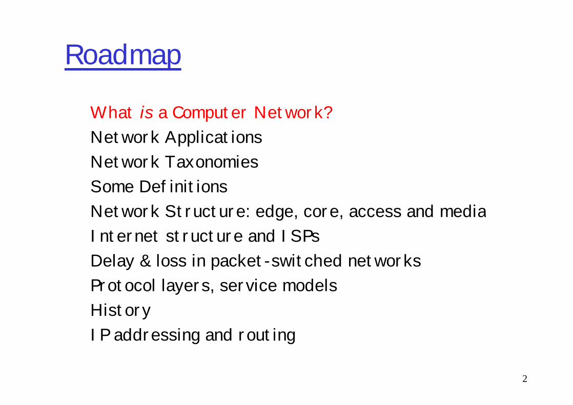
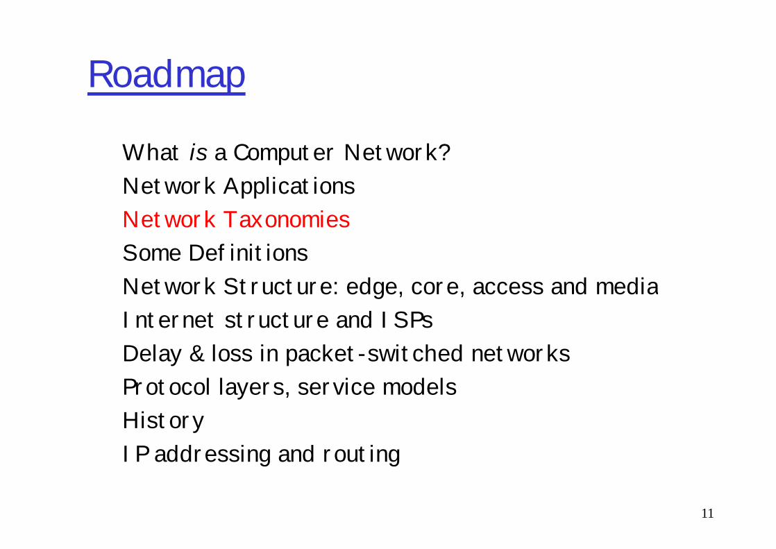
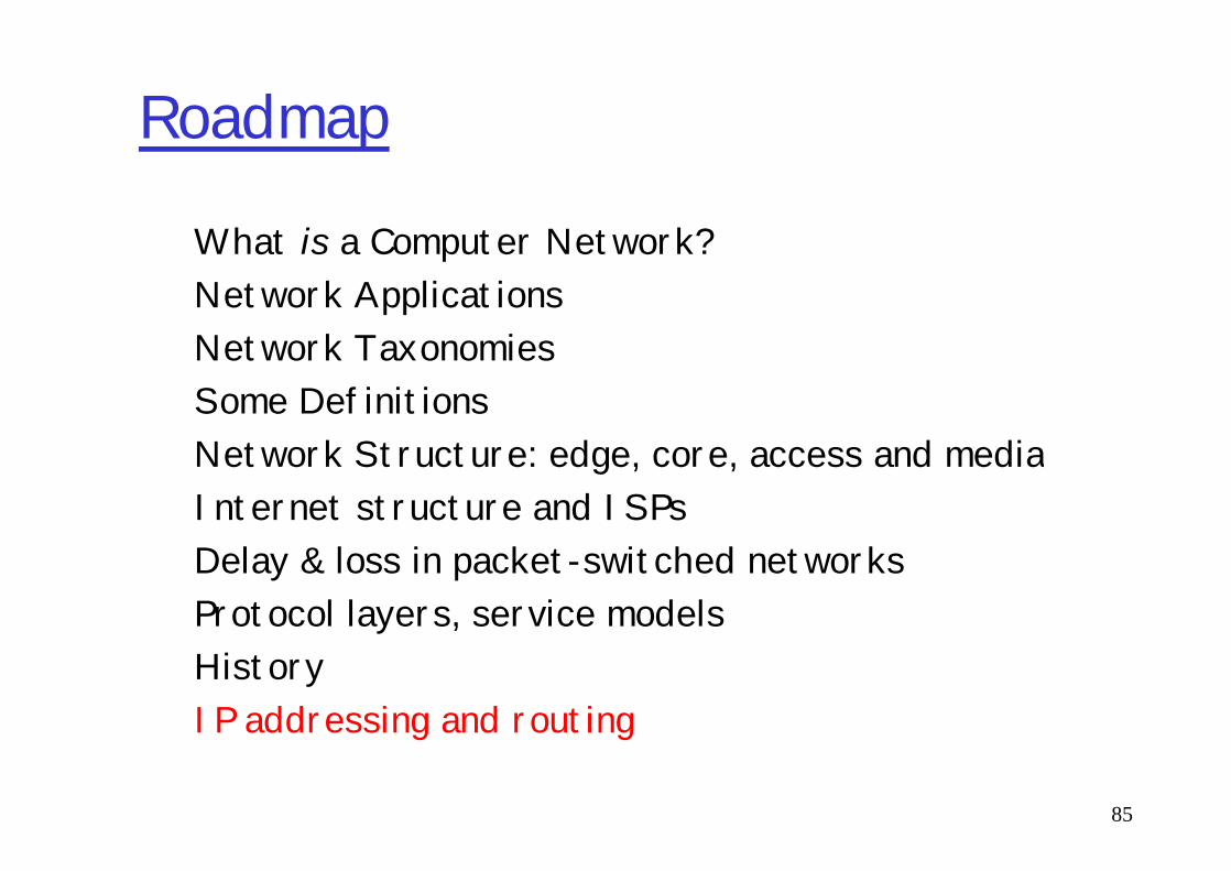
Roadmap
What is a Computer Network?Network ApplicationsNetwork TaxonomiesSome DefinitionsNetwork Structure: edge, core, access and media
2
Network Structure: edge, core, access and mediaInternet structure and ISPsDelay & loss in packet-switched networksProtocol layers, service modelsHistoryIP addressing and routing
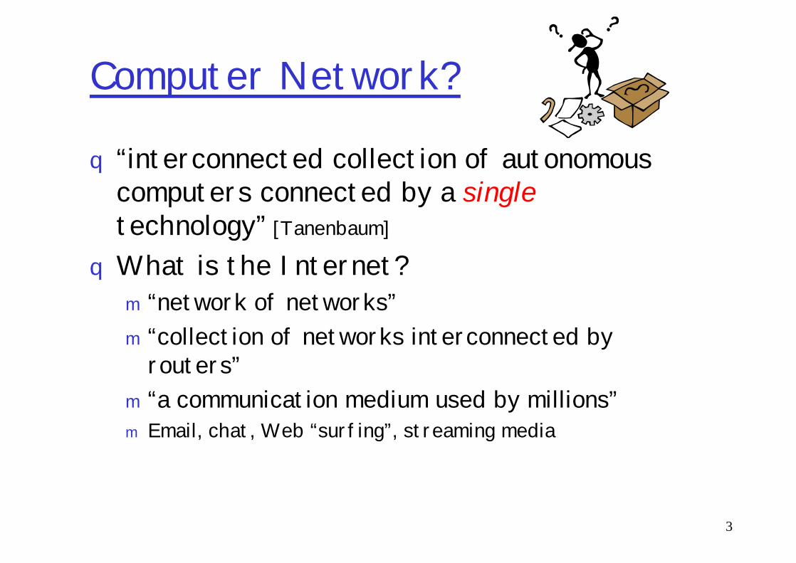
Computer Network?
q “interconnected collection of autonomous computers connected by a singletechnology” [Tanenbaum]
qWhat is the Internet?
3
What is the Internet?m “network of networks”m “collection of networks interconnected by
routers”m “a communication medium used by millions”m Email, chat, Web “surfing”, streaming media
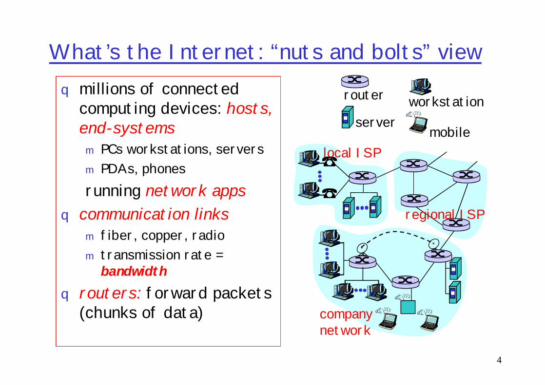
What’s the Internet: “nuts and bolts” viewq millions of connected
computing devices: hosts, end-systemsm PCs workstations, serversm PDAs, phonesrunning network apps
local ISP
router workstationserver
mobile
4
running network appsq communication links
m fiber, copper, radiom transmission rate =
bandwidthq routers: forward packets
(chunks of data) companynetwork
regional ISP
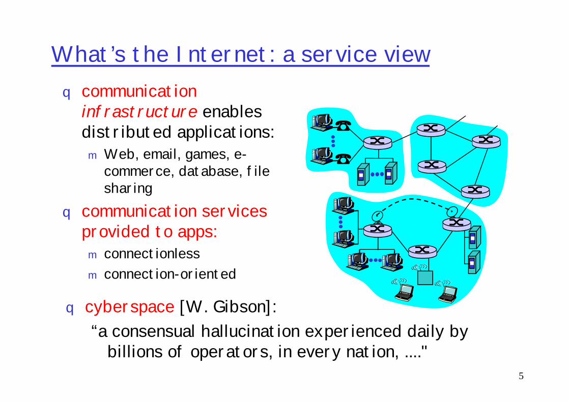
What’s the Internet: a service viewq communication
infrastructure enables distributed applications:m Web, email, games, e-
commerce, database, file sharing
communication services
5
q communication services provided to apps:m connectionlessm connection-oriented
q cyberspace [W. Gibson]:“a consensual hallucination experienced daily by
billions of operators, in every nation, ...."

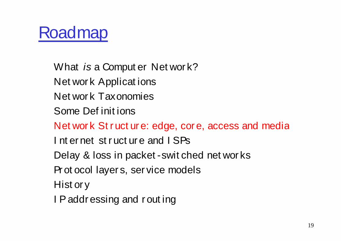
Roadmap
What is a Computer Network?Network ApplicationsNetwork TaxonomiesSome DefinitionsNetwork Structure: edge, core, access and media
6
Network Structure: edge, core, access and mediaInternet structure and ISPsDelay & loss in packet-switched networksProtocol layers, service modelsHistoryIP addressing and routing

Applications (1)q end systems (hosts):
m run application programsm e.g. Web, emailm at “edge of network”
q client/server model
7
client/server modelm client host requests, receives
service from always-on serverm e.g. Web browser/server;
email client/server

Applications (2)q peer-2-peer model:
m No fixed clients or serversm Each host can act as both client & server
q Examples: Napster, Gnutella, KaZaA, Torrent
8

Applications (3)qWWWq File Transfer (FTP, SMB, Peer-to-Peer)q E-mailq Instant Messaging (Internet chat, text
messaging)
9
messaging)q Remote Login and Terminals (SSH, RDP)q Internet Phoneq Video-on-demandqNetwork Games

“Cool” internet appliances
IP picture framehttp://www.ceiva.com/
10
World’s smallest web serverhttp://www-ccs.cs.umass.edu/~shri/iPic.html
Roadmap
What is a Computer Network?Network ApplicationsNetwork TaxonomiesSome DefinitionsNetwork Structure: edge, core, access and media
11
Network Structure: edge, core, access and mediaInternet structure and ISPsDelay & loss in packet-switched networksProtocol layers, service modelsHistoryIP addressing and routing

Network Taxonomy: Topologies
12
q Network topology – configuration of nodes interconnection (which is absent at this figure?)

Network Taxonomy: on a network scale
Scale BER, bit
error ratio Nerr/Ntx
Maximum distance between nodes, km
Typical transfer rate, Mbps Lines are in
PAN* 10-7 – 10-9 0.1** 1-10 private property -9
13
LAN* 10-9 1 10-10000*** private property
MAN* 10-6 50 622-2488 private or municipal property
WAN* 10-3 – 10-5 > 50 10-2488 property of tel.co. Notes:
* PAN, LAN, MAN, WAN = Personal, Local, Metropolitan, Wide Area Network
** IEEE 802.15.1, Bluetooth
*** IEEE 802.3ae/an, 10Gigabit Ethernet

Roadmap
What is a Computer Network?Network ApplicationsNetwork TaxonomiesSome more DefinitionsNetwork Structure: edge, core, access and media
14
Network Structure: edge, core, access and mediaInternet structure and ISPsDelay & loss in packet-switched networksProtocol layers, service modelsHistoryIP addressing and routing

Low-level network structure
digital interface
digital interface DTE DCE DCE DTE phy.
medium
Host A Host B
DTE – Data Terminating Equipment DCE - Data Circuit-terminating Equipment
15
Host A Host B
Host C
digital interface DTE DCE
phy. medium
digital interface DCE DTE
digital interface DCE DTE
Point-to-point and multipoint configurations

Data Flowsq Duplex (full-duplex)q Half-duplexq Simplex
16

What’s a protocol?human protocols:q “what’s the time?”q “I have a question”q introductions
network protocols:q machines rather than
humansq all communication
activity in Internet governed by protocols
17
… specific msgs sent… specific actions taken
when msgs received, or other events
governed by protocols
protocols define: format, order of msgs sent and received among network
entities, and actionstaken on msg
transmission, receipt
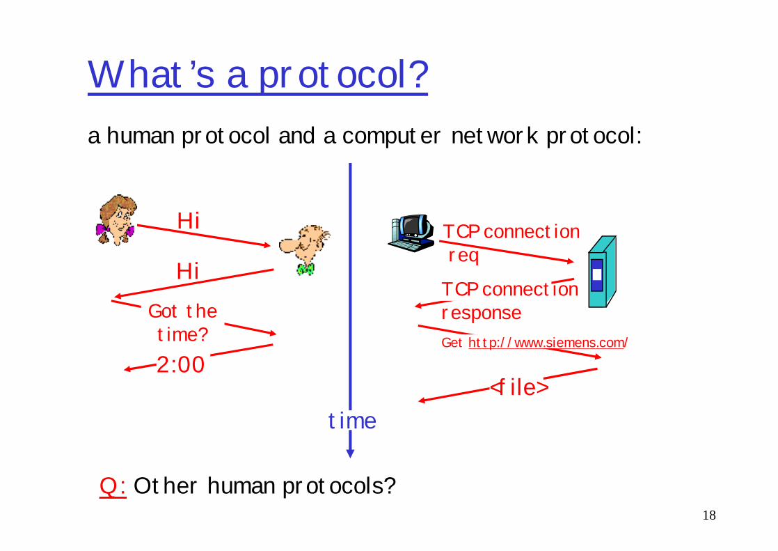
What’s a protocol?a human protocol and a computer network protocol:
Hi
HiTCP connectionreq
TCP connection
18
Q: Other human protocols?
HiGot thetime?2:00
TCP connectionresponseGet http://www.siemens.com/
<file>time
Roadmap
What is a Computer Network?Network ApplicationsNetwork TaxonomiesSome DefinitionsNetwork Structure: edge, core, access and media
19
Network Structure: edge, core, access and mediaInternet structure and ISPsDelay & loss in packet-switched networksProtocol layers, service modelsHistoryIP addressing and routing

A closer look at network structure:
q network edge:applications and hosts
q network core:
20
network core:m routersm network of
networksq access networks,
physical media:communication links
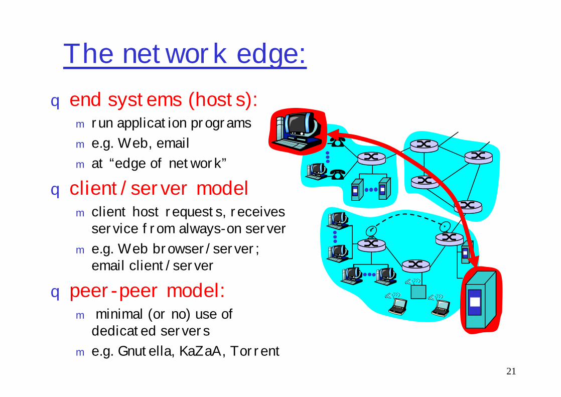
The network edge:q end systems (hosts):
m run application programsm e.g. Web, emailm at “edge of network”
q client/server model
21
client/server modelm client host requests, receives
service from always-on serverm e.g. Web browser/server;
email client/server
q peer-peer model:m minimal (or no) use of
dedicated serversm e.g. Gnutella, KaZaA, Torrent

Network edge: connection-oriented service
Goal: data transfer between end systems
q handshaking: setup (prepare for) data transfer ahead of time
TCP service [RFC 793]q reliable, in-order byte-
stream data transferm loss: acknowledgements
and retransmissions
22
transfer ahead of timem Hello, hello back human
protocolm set up “state” in two
communicating hostsq TCP - Transmission
Control Protocol m Internet’s connection-
oriented service
and retransmissionsq flow control:
m sender won’t overwhelm receiver
q congestion control:m senders “slow down sending
rate” when network congested

Network edge: connectionless service
Goal: data transfer between end systemsm same as before!
q UDP - User Datagram Protocol [RFC 768]:
App’s using TCP:q HTTP (Web), FTP (file
transfer), Telnet (remote login), SMTP (email)
23
Protocol [RFC 768]: Internet’s connectionless servicem unreliable data
transferm no flow controlm no congestion control
(email)
App’s using UDP:q streaming media,
teleconferencing, DNS, Internet telephony
q Q: Why m/media?

The Network Core
q mesh of interconnected routers
q the fundamental question: how is data transferred through net?
24
transferred through net?m circuit switching:
dedicated circuit per call: telephone net
m packet-switching: data sent thru net in discrete “chunks”

Network Core: Circuit Switching
End-end resources reserved for “call”
q link bandwidth, switch capacitydedicated resources:
25
q dedicated resources: no sharing
q circuit-like (guaranteed) performance
q call setup required
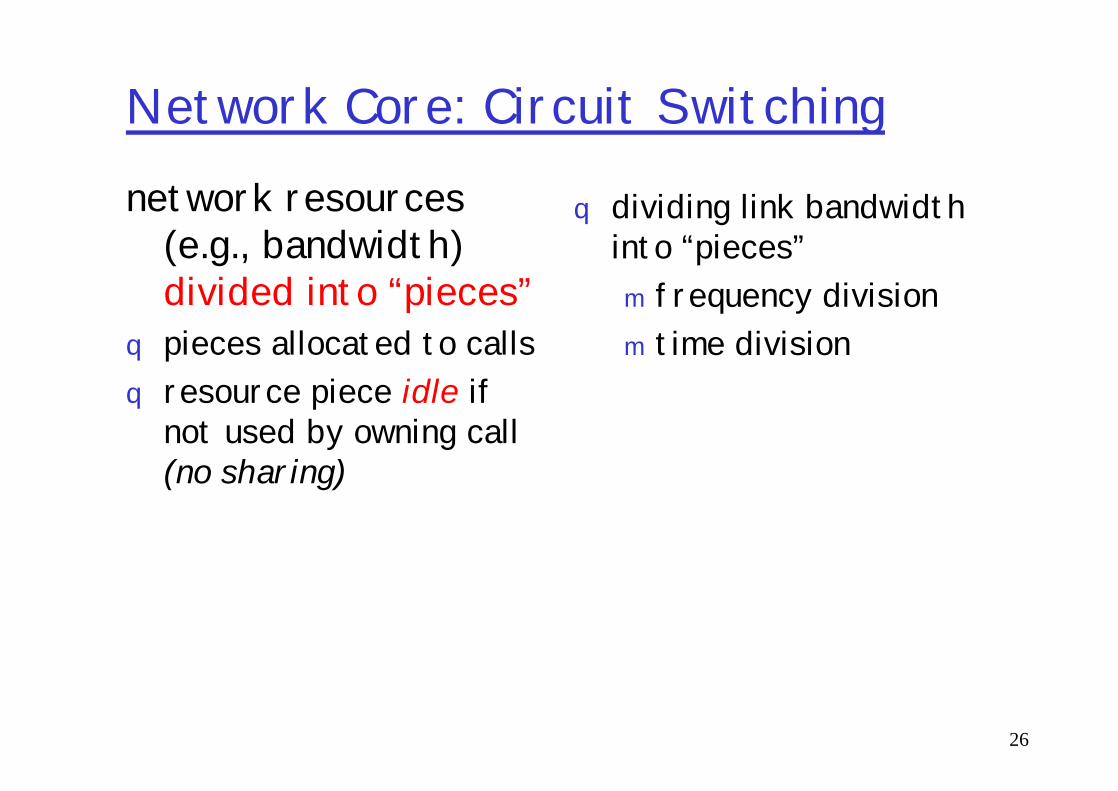
Network Core: Circuit Switchingnetwork resources
(e.g., bandwidth) divided into “pieces”
q pieces allocated to callsq resource piece idle if
q dividing link bandwidth into “pieces”m frequency divisionm time division
26
q resource piece idle if not used by owning call (no sharing)

Circuit Switching: FDMA and TDMA
FDMA
frequency
4 usersExample:
27
timeTDMA
frequency
time
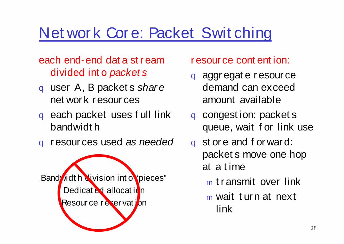
Network Core: Packet Switchingeach end-end data stream
divided into packetsq user A, B packets share
network resourcesq each packet uses full link
bandwidth
resource contention:q aggregate resource
demand can exceed amount available
q congestion: packets queue, wait for link use
28
bandwidth q resources used as needed
queue, wait for link useq store and forward:
packets move one hop at a timem transmit over linkm wait turn at next
link
Bandwidth division into “pieces”Dedicated allocationResource reservation
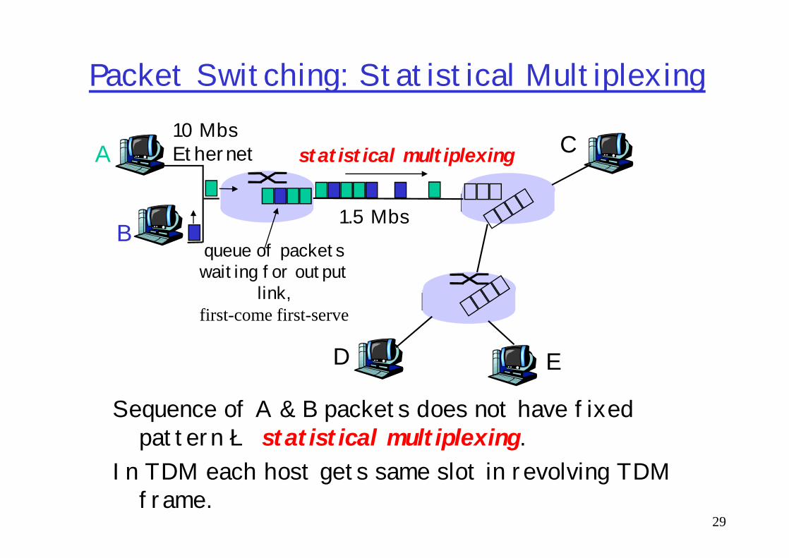
Packet Switching: Statistical Multiplexing
A
B
C10 MbsEthernet
1.5 Mbs
statistical multiplexing
queue of packetswaiting for output
29
Sequence of A & B packets does not have fixed pattern è statistical multiplexing.
In TDM each host gets same slot in revolving TDM frame.
D E
waiting for outputlink,
first-come first-serve

Packet switching versus circuit switching
q Great for bursty datam resource sharingm simpler, no call setup
q Excessive congestion: packet delay and loss
Is packet switching a “slam dunk winner?”
30
q Excessive congestion: packet delay and lossm protocols needed for reliable data transfer,
congestion controlq Q: How to provide circuit-like behavior?m bandwidth guarantees needed for audio/video
apps

Packet-switched networks: forwarding
q Goal: move packets through routers from source to destination
q datagram network:m destination address in packet determines next hopm routes may change during session
analogy: driving, asking directions
31
m analogy: driving, asking directions q virtual circuit network:
m each packet carries tag (virtual circuit ID), tag determines next hop
m fixed path determined at call setup time, remains fixed thru call
m network equipment maintain per-call state

Yet another Network TaxonomyTelecommunication
networks
Circuit-switchednetworks
Packet-switchednetworks
32
FDM TDM Networkswith VCs
DatagramNetworks
• Datagram network is not either connection-oriented or connectionless.• Internet provides both connection-oriented (TCP) and connectionless services (UDP) to apps.
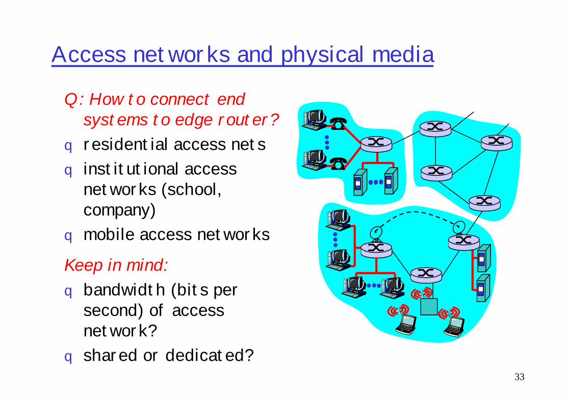
Access networks and physical media
Q: How to connect end systems to edge router?
q residential access netsq institutional access
networks (school, company)
33
company)q mobile access networks
Keep in mind: q bandwidth (bits per
second) of access network?
q shared or dedicated?
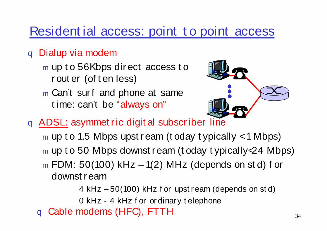
Residential access: point to point accessq Dialup via modemm up to 56Kbps direct access to
router (often less)m Can’t surf and phone at same
time: can’t be “always on”
ADSL: asymmetric digital subscriber line
34
q ADSL: asymmetric digital subscriber linem up to 1.5 Mbps upstream (today typically < 1 Mbps)m up to 50 Mbps downstream (today typically<24 Mbps)m FDM: 50(100) kHz – 1(2) MHz (depends on std) for
downstream4 kHz – 50(100) kHz for upstream (depends on std)0 kHz - 4 kHz for ordinary telephone
q Cable modems (HFC), FTTH

Company access: local area networks
q company/univ local area network (LAN) connects end system to edge router
q Ethernet:m shared or dedicated link
connects end system
35
connects end system and router
m 10 Mbs, 100Mbps, 1-10 Gigabit Ethernet
q deployment: institutions, home LANs happening now
q LANs: will study further

Wireless access networksq shared wireless access network
connects end system to routerm via base station aka “access point”
q wireless LANs:m 802.11b/g/n (WiFi): 11/54/300-
600 Mbpsbase
station
router
36
600 Mbpsm Infrastructure and Ad-Hoc modes
q wider-area wireless accessm provided by telco operatorm 3Gm WAP/GPRS
station
mobilehosts
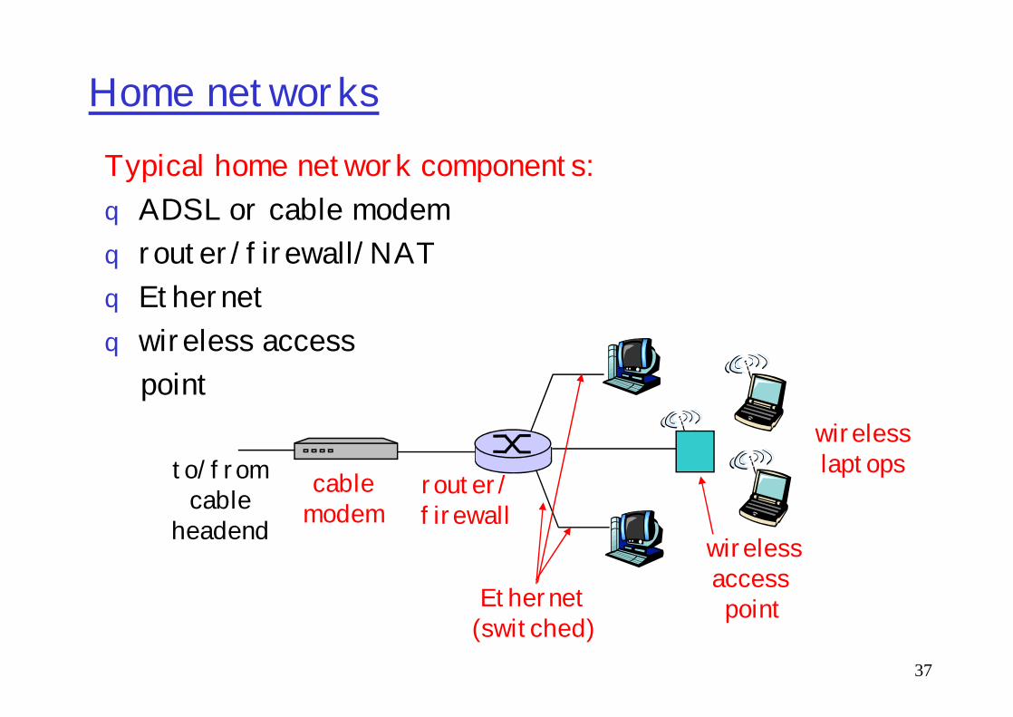
Home networksTypical home network components: q ADSL or cable modemq router/firewall/NATq Ethernetq wireless access
37
wireless accesspoint
wirelessaccess point
wirelesslaptops
router/firewall
cablemodem
to/fromcable
headend
Ethernet(switched)

Physical Media
q Bit: propagates betweentransmitter/rcvr pairs
q physical link: what lies between transmitter & receiver
Twisted Pair (TP)q two insulated copper
wiresm Category 3: traditional
phone wires, 10 Mbps Ethernet
38
receiverq guided media:
m signals propagate in solid media: copper, fiber, coax
q unguided media:m signals propagate freely,
e.g., radio
Ethernetm Category 5, 5e, 6, 6a, 7:
100 .. 10000Mbps

Guided media: coax-cable, TP, FO
39

Unguided media
40

IR lasers
41

Electromagnetic spectrum
42

FO cables: MMF, SMF
43

FO: attenuation in IR region
44
Physical Media: coax, fiber
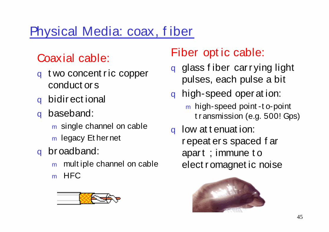
Coaxial cable:q two concentric copper
conductorsq bidirectionalq baseband:
Fiber optic cable:q glass fiber carrying light
pulses, each pulse a bitq high-speed operation:
m high-speed point-to-point transmission (e.g. 500! Gps)
45
q baseband:m single channel on cablem legacy Ethernet
q broadband:m multiple channel on cablem HFC
transmission (e.g. 500! Gps)q low attenuation:
repeaters spaced far apart ; immune to electromagnetic noise
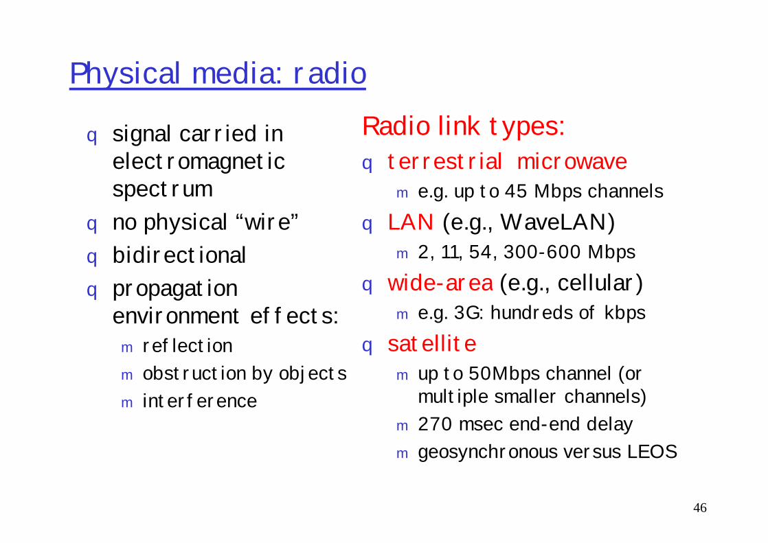
Physical media: radio
q signal carried in electromagnetic spectrum
q no physical “wire”q bidirectional
propagation
Radio link types:q terrestrial microwave
m e.g. up to 45 Mbps channelsq LAN (e.g., WaveLAN)
m 2, 11, 54, 300-600 Mbpswide-area (e.g., cellular)
46
q propagation environment effects:m reflection m obstruction by objectsm interference
q wide-area (e.g., cellular)m e.g. 3G: hundreds of kbps
q satellitem up to 50Mbps channel (or
multiple smaller channels)m 270 msec end-end delaym geosynchronous versus LEOS

Roadmap
What is a Computer Network?Network ApplicationsNetwork TaxonomiesSome DefinitionsNetwork Structure: edge, core, access and media
47
Network Structure: edge, core, access and mediaInternet structure and ISPsDelay & loss in packet-switched networksProtocol layers, service modelsHistoryIP addressing and routing
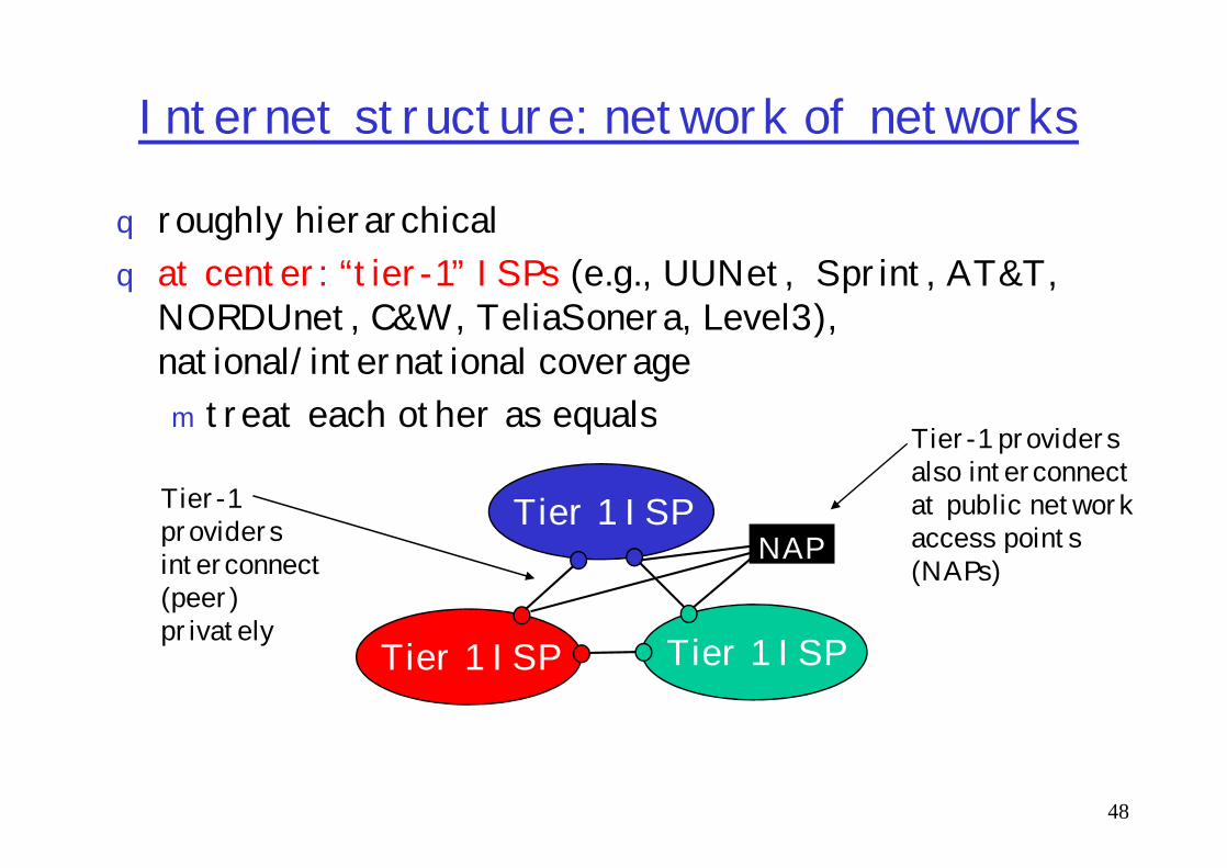
Internet structure: network of networks
q roughly hierarchicalq at center: “tier-1” ISPs (e.g., UUNet, Sprint, AT&T,
NORDUnet, C&W, TeliaSonera, Level3), national/international coveragem treat each other as equals
Tier-1 providers
48
treat each other as equals
Tier 1 ISP
Tier 1 ISP
Tier 1 ISP
Tier-1 providers interconnect (peer) privately
NAP
Tier-1 providers also interconnect at public network access points (NAPs)

Tier-1 ISP: e.g., SprintSprint US backbone network
49

Internet structure: network of networks
q “Tier-2” ISPs: smaller (often regional) ISPsm Connect to one or more tier-1 ISPs, possibly other tier-2 ISPs
Tier-2 ISPTier-2 ISP pays Tier-2 ISPs also peer
50
Tier 1 ISP
Tier 1 ISP
Tier 1 ISP
NAP
Tier-2 ISPTier-2 ISP
Tier-2 ISP Tier-2 ISP
Tier-2 ISP
Tier-2 ISP pays tier-1 ISP for connectivity to rest of Internetq tier-2 ISP is customer oftier-1 provider
also peer privately with each other, interconnect at NAP
Internet structure: network of networks
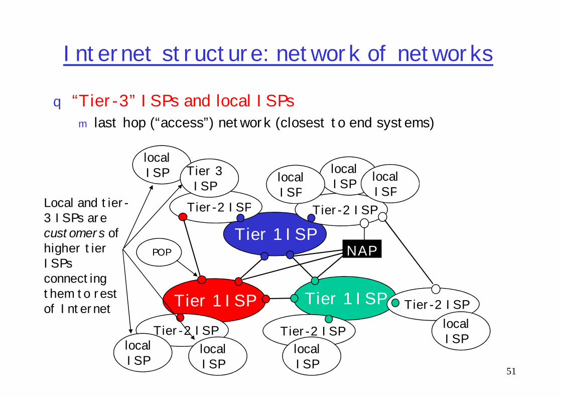
q “Tier-3” ISPs and local ISPs m last hop (“access”) network (closest to end systems)
Tier-2 ISP
localISPlocal
ISPlocalISP
localISP Tier 3
ISPLocal and tier-
51
Tier 1 ISP
Tier 1 ISP
Tier 1 ISP
NAP
Tier-2 ISPTier-2 ISP
Tier-2 ISP Tier-2 ISP
Tier-2 ISP
ISP ISP
localISP
localISP
localISP
localISP
Local and tier-3 ISPs are customers ofhigher tier ISPsconnecting them to rest of Internet
POP

Internet structure: network of networks
q a packet passes through many networks!
Tier-2 ISP
localISPlocal
ISPlocalISP
localISP Tier 3
ISP
52
Tier 1 ISP
Tier 1 ISP
Tier 1 ISP
NAP
Tier-2 ISPTier-2 ISP
Tier-2 ISP Tier-2 ISP
Tier-2 ISP
ISP ISP
localISP
localISP
localISP
localISP

MSK-IX
53
M9-IX1Gbps

Typical usage of Internet eXchange (IX)
54


Roadmap
What is a Computer Network?Network ApplicationsNetwork TaxonomiesSome DefinitionsNetwork Structure: edge, core, access and media
56
Network Structure: edge, core, access and mediaInternet structure and ISPsDelay & loss in packet-switched networksProtocol layers, service modelsHistoryIP addressing and routing
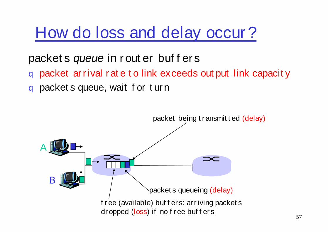
How do loss and delay occur?packets queue in router buffersq packet arrival rate to link exceeds output link capacityq packets queue, wait for turn
packet being transmitted (delay)
57
A
B
packet being transmitted (delay)
packets queueing (delay)free (available) buffers: arriving packets dropped (loss) if no free buffers
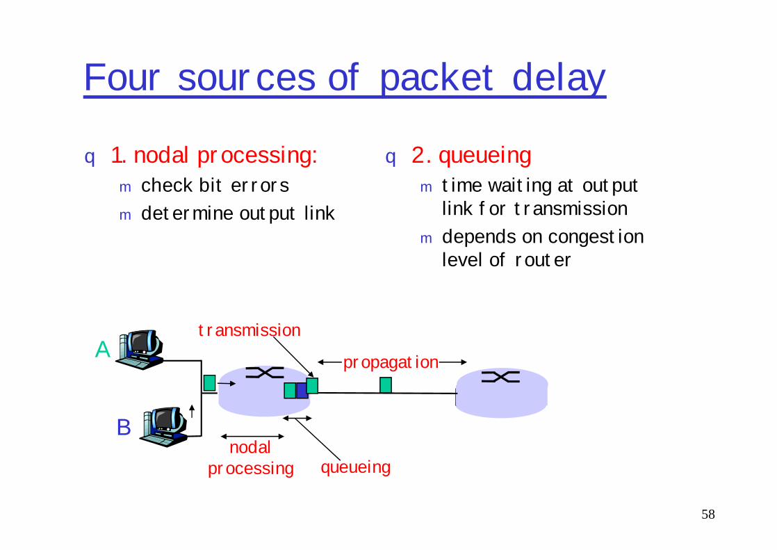
Four sources of packet delay
q 1. nodal processing:m check bit errorsm determine output link
q 2. queueingm time waiting at output
link for transmission m depends on congestion
level of router
58
A
B
propagation
transmission
nodalprocessing queueing
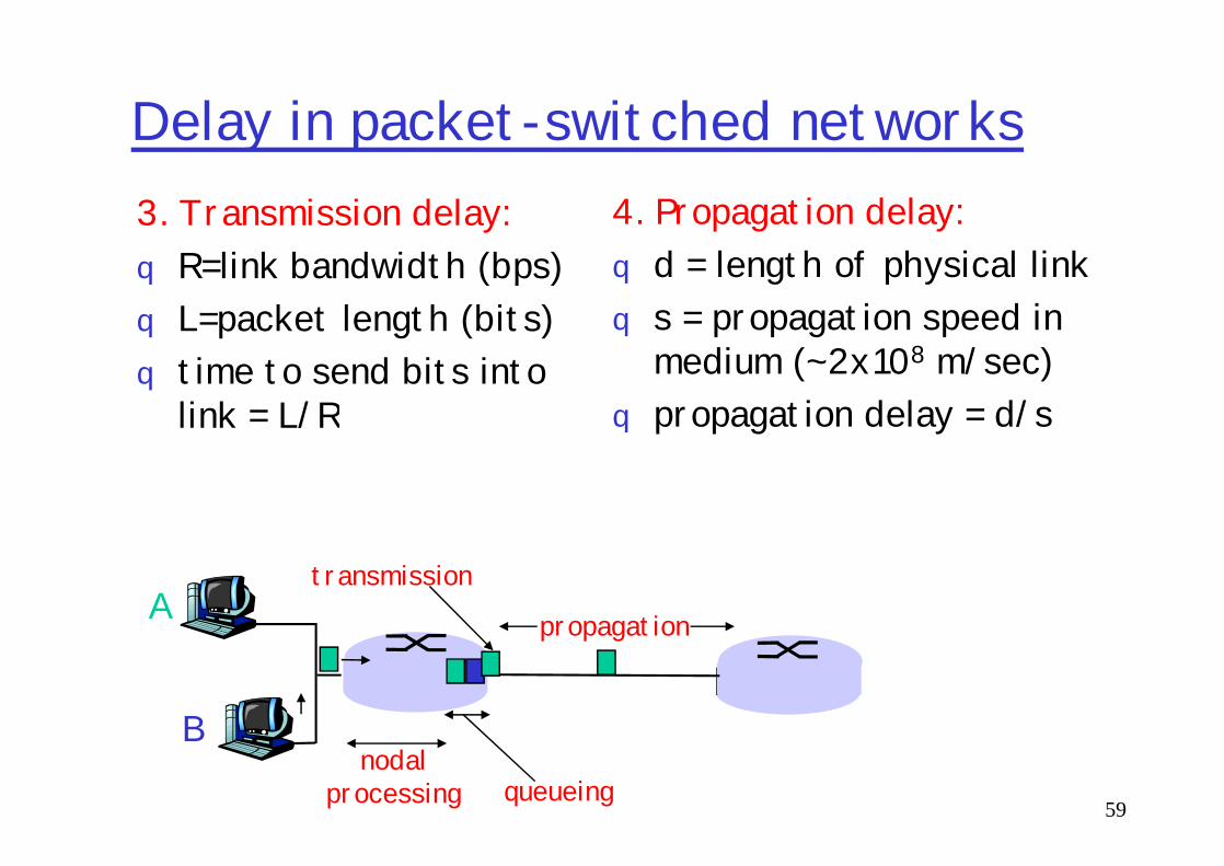
Delay in packet-switched networks3. Transmission delay:q R=link bandwidth (bps)q L=packet length (bits)q time to send bits into
link = L/R
4. Propagation delay:q d = length of physical linkq s = propagation speed in
medium (~2x10⁸ m/sec)q propagation delay = d/s
59
link = L/R q propagation delay = d/s
A
B
propagation
transmission
nodalprocessing queueing
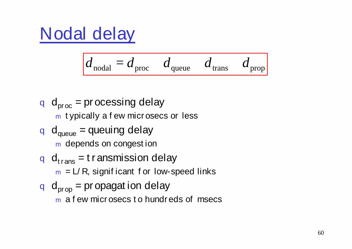
Nodal delay
q dproc = processing delaym typically a few microsecs or less
d = queuing delay
proptransqueueprocnodal ddddd +++=
60
q dqueue = queuing delaym depends on congestion
q dtrans = transmission delaym = L/R, significant for low-speed links
q dprop = propagation delaym a few microsecs to hundreds of msecs
“Real” Internet delays and routes
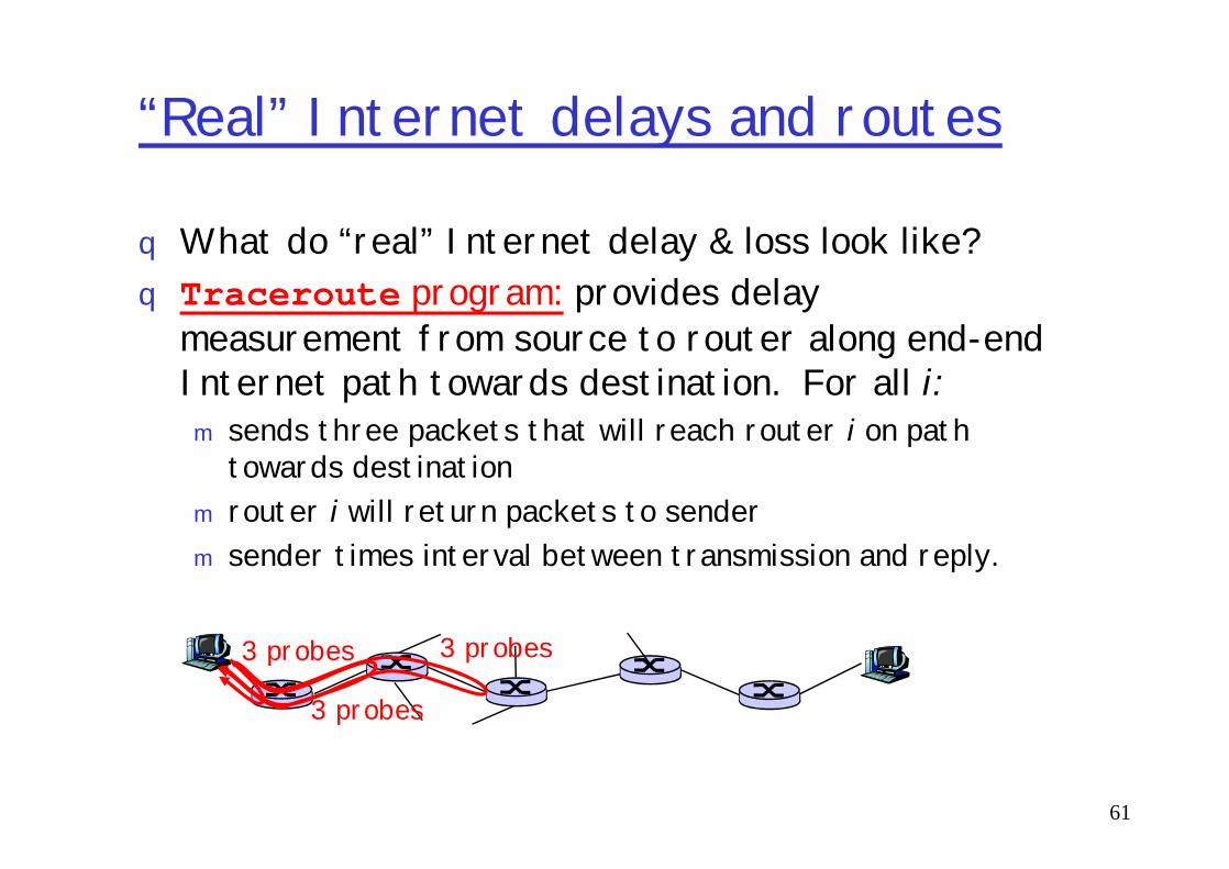
q What do “real” Internet delay & loss look like? q Traceroute program: provides delay
measurement from source to router along end-end Internet path towards destination. For all i:m sends three packets that will reach router i on path
61
m sends three packets that will reach router i on path towards destination
m router i will return packets to senderm sender times interval between transmission and reply.
3 probes
3 probes
3 probes
“Real” Internet delays and routes
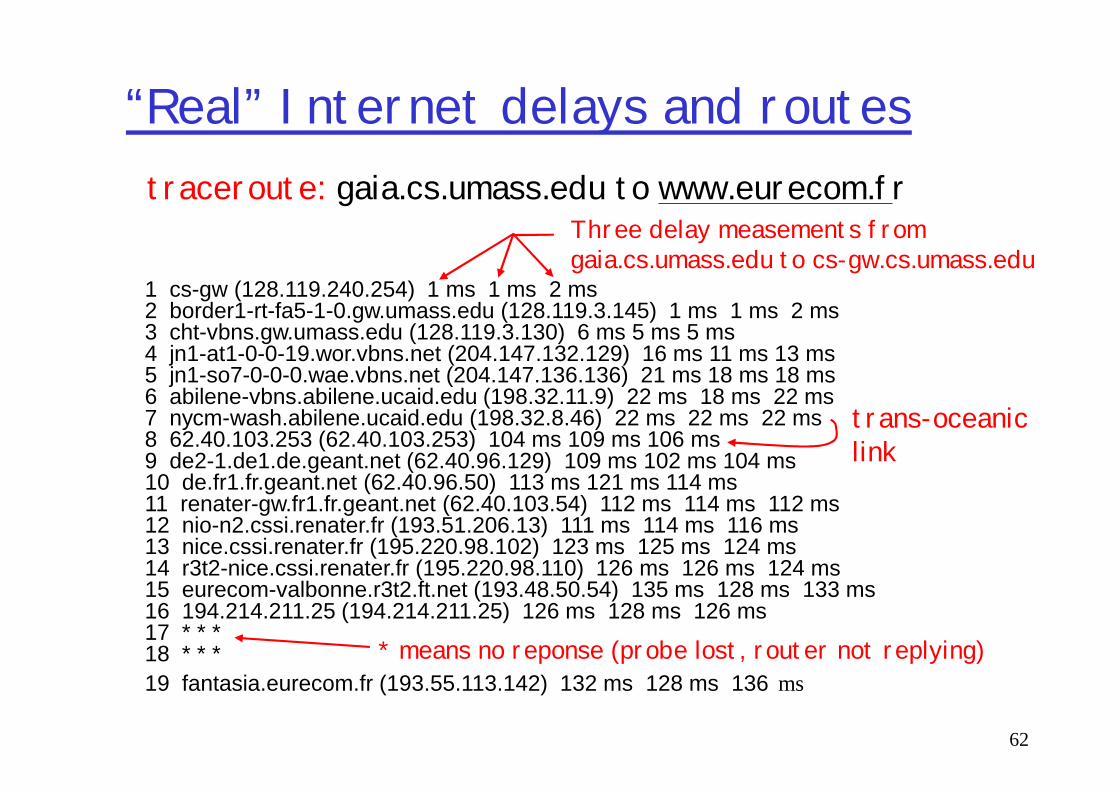
1 cs-gw (128.119.240.254) 1 ms 1 ms 2 ms2 border1-rt-fa5-1-0.gw.umass.edu (128.119.3.145) 1 ms 1 ms 2 ms3 cht-vbns.gw.umass.edu (128.119.3.130) 6 ms 5 ms 5 ms4 jn1-at1-0-0-19.wor.vbns.net (204.147.132.129) 16 ms 11 ms 13 ms 5 jn1-so7-0-0-0.wae.vbns.net (204.147.136.136) 21 ms 18 ms 18 ms 6 abilene-vbns.abilene.ucaid.edu (198.32.11.9) 22 ms 18 ms 22 ms
traceroute: gaia.cs.umass.edu to www.eurecom.frThree delay measements from gaia.cs.umass.edu to cs-gw.cs.umass.edu
62
6 abilene-vbns.abilene.ucaid.edu (198.32.11.9) 22 ms 18 ms 22 ms7 nycm-wash.abilene.ucaid.edu (198.32.8.46) 22 ms 22 ms 22 ms8 62.40.103.253 (62.40.103.253) 104 ms 109 ms 106 ms9 de2-1.de1.de.geant.net (62.40.96.129) 109 ms 102 ms 104 ms10 de.fr1.fr.geant.net (62.40.96.50) 113 ms 121 ms 114 ms11 renater-gw.fr1.fr.geant.net (62.40.103.54) 112 ms 114 ms 112 ms12 nio-n2.cssi.renater.fr (193.51.206.13) 111 ms 114 ms 116 ms13 nice.cssi.renater.fr (195.220.98.102) 123 ms 125 ms 124 ms14 r3t2-nice.cssi.renater.fr (195.220.98.110) 126 ms 126 ms 124 ms15 eurecom-valbonne.r3t2.ft.net (193.48.50.54) 135 ms 128 ms 133 ms16 194.214.211.25 (194.214.211.25) 126 ms 128 ms 126 ms17 * * *18 * * *19 fantasia.eurecom.fr (193.55.113.142) 132 ms 128 ms 136 ms
* means no reponse (probe lost, router not replying)
trans-oceaniclink

Packet loss
q queue (aka buffer) preceding link in buffer has finite capacity
q when packet arrives to full queue, packet is dropped (aka lost)
63
dropped (aka lost)q lost packet may be retransmitted by
previous node, by source end system, or not retransmitted at all

Roadmap
What is a Computer Network?Network ApplicationsNetwork TaxonomiesSome DefinitionsNetwork Structure: edge, core, access and media
64
Network Structure: edge, core, access and mediaInternet structure and ISPsDelay & loss in packet-switched networksProtocol layers, service modelsHistoryIP addressing and routing

Protocol “Layers”Networks are complex! q many “pieces”:m hostsm routersm links of various
Question:Is there any hope of organizing structure of
65
m links of various media
m applicationsm protocolsm hardware,
software
organizing structure of network?
Or at least our discussion of networks?

Why layering?Dealing with complex systems:q explicit structure allows identification,
relationship of complex system’s piecesm layered reference model for discussion
q modularization eases maintenance, updating of
66
q modularization eases maintenance, updating of systemm change of implementation of layer’s service
transparent to rest of systemm e.g., change in gate procedure doesn’t affect
rest of systemq layering considered harmful?

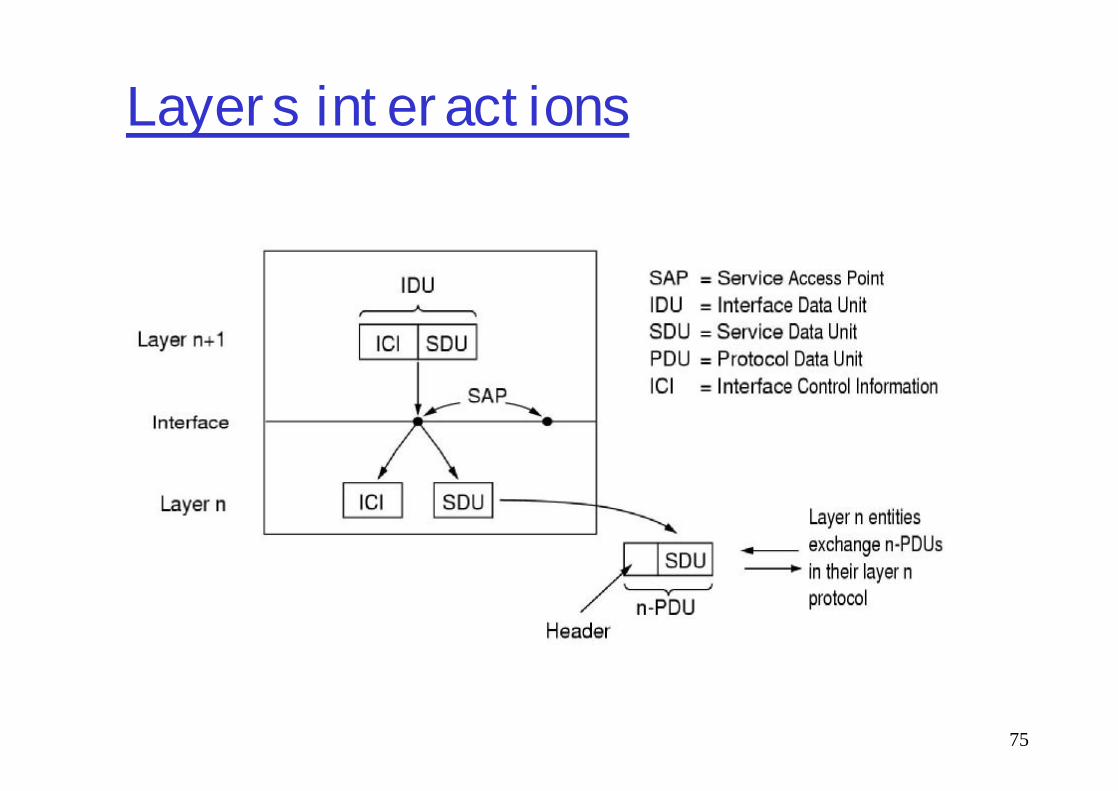
Layers, Protocols, Interfaces
Application logicprotocol
Reliable delivery
ApplicationServices
Communication
ApplicationServices
Communication
Layer Interface
67
Web Server Web Client
Reliable deliveryprotocol
Transfer “bits”protocol
Network Services
CommunicationService
Network Services
CommunicationService
Layer Interface

Layered Architecture (Review 1/2)
qNetworks organized as a stack of layers?m The purpose of a layer is to offer services to
the layer above it using an interface(programming language analogy: libraries hide details while providing a service)Reduces design complexity
68
details while providing a service)m Reduces design complexity
q Protocols: peer-to-peer layer-n conversations
qData Transfer: each layer passes data & control information to the layer below; eventually physical medium is reached.

Layered Architecture Review (2/2)
qA set of layers & protocols sometimes is called a Network Architecture. These specifications enable hardware/software developers to build systems compliant with a particular architecture.
69
a particular architecture.m E.g., TCP/IP, OSI
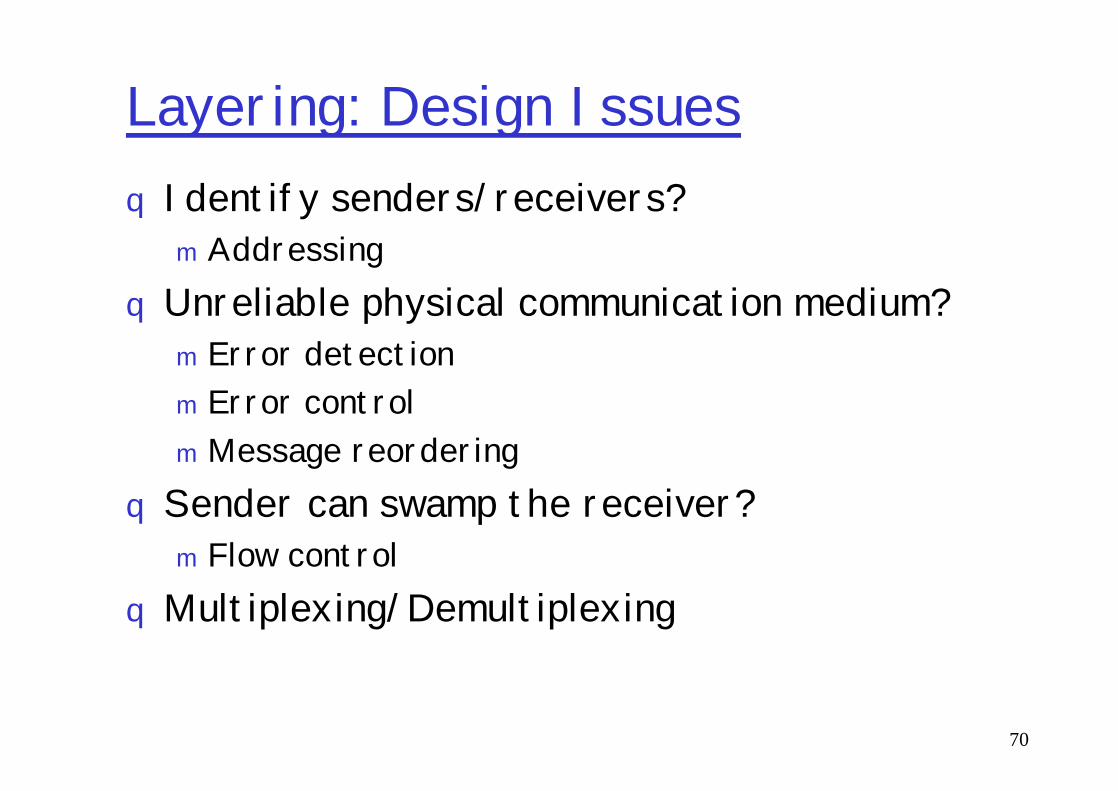
Layering: Design Issuesq Identify senders/receivers?m Addressing
qUnreliable physical communication medium?m Error detectionm Error control
70
m Error controlmMessage reordering
qSender can swamp the receiver?m Flow control
qMultiplexing/Demultiplexing

Reference Models
q TCP/IP ModelqOpen Systems Interconnection (OSI)
Model
71

TCP/IP Model: History
qOriginally used in the ARPANETqARPANET required networks
using leased telephone lines & radio/satellite networks to interoperate
Application
Transport(Host-2-Host)
Internet
72
radio/satellite networks to interoperate
q Goals of the model are:m Seamless interoperabilitymWide-ranging applicationsm Fault-tolerant to some extent
Internet
Host-to-Network
(Network Access)

OSI/ISO (1984)
73
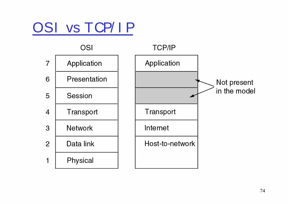
OSI vs TCP/IP
74
Layers interactions
75
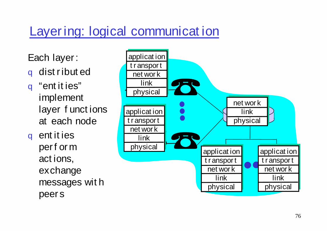
Layering: logical communication
applicationtransportnetwork
linkphysical
applicationtransport
networklink
physical
Each layer:q distributedq “entities”
implement layer functions at each node
76
applicationtransportnetwork
linkphysical application
transportnetwork
linkphysical
applicationtransportnetwork
linkphysical
linkphysical
layer functions at each node
q entities perform actions, exchange messages with peers

Layering: logical communication
applicationtransportnetwork
linkphysical
applicationtransport
networklink
physical
dataE.g.: transportq take data from appq add addressing,
reliability check info to form “datagram”
transport
ack
77
applicationtransportnetwork
linkphysical application
transportnetwork
linkphysical
applicationtransportnetwork
linkphysical
linkphysical
data
“datagram”q send datagram to
peerq wait for peer to
ack receiptq analogy: post
office
data
transport

Layering: physical communication
applicationtransportnetwork
linkphysical
applicationnetwork
link
data
78
applicationtransportnetwork
linkphysical
applicationtransportnetwork
linkphysical
applicationtransportnetwork
linkphysical
linkphysical
data
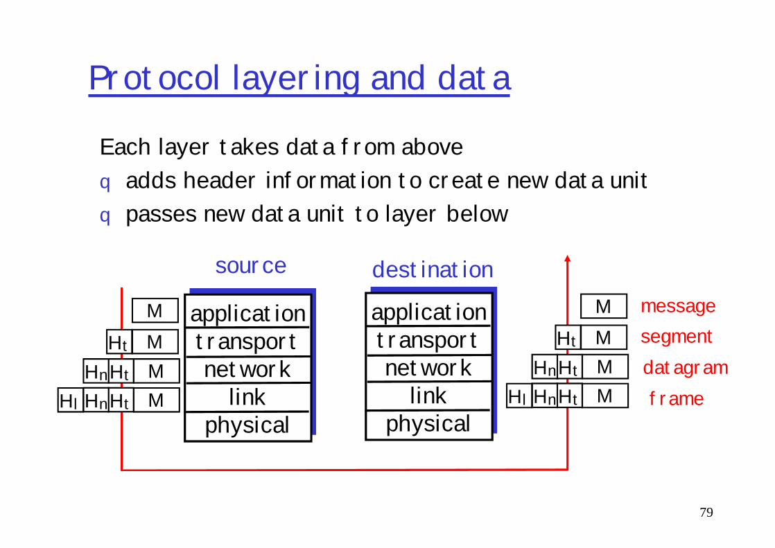
Protocol layering and data
Each layer takes data from aboveq adds header information to create new data unitq passes new data unit to layer below
source destination
79
applicationtransportnetwork
linkphysical
applicationtransportnetwork
linkphysical
source destinationMMMM
Ht
HtHnHtHnHl
MMMM
Ht
HtHnHtHnHl
messagesegmentdatagramframe
Roadmap
What is a Computer Network?Network ApplicationsNetwork TaxonomiesSome DefinitionsNetwork Structure: edge, core, access and media
80
Network Structure: edge, core, access and mediaInternet structure and ISPsDelay & loss in packet-switched networksProtocol layers, service modelsHistoryIP addressing and routing
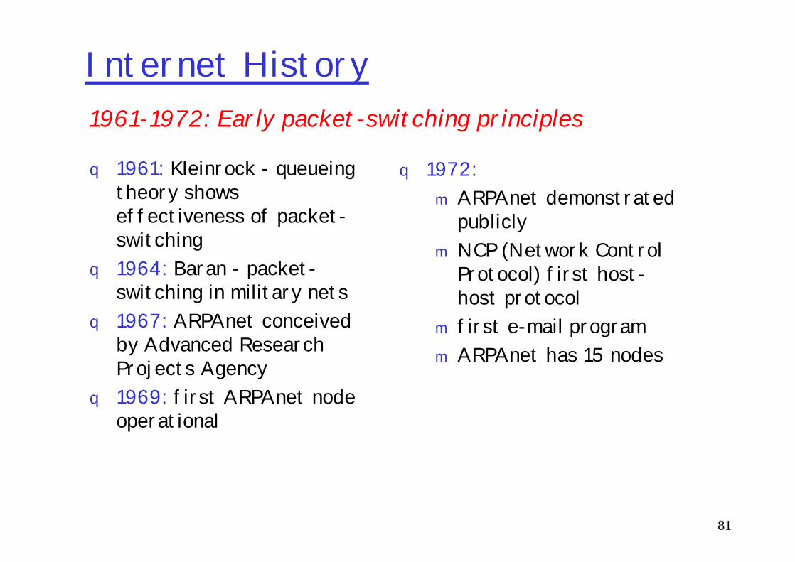
Internet History
q 1961: Kleinrock - queueing theory shows effectiveness of packet-switching
q 1964: Baran - packet-switching in military nets
q 1972:m ARPAnet demonstrated
publiclym NCP (Network Control
Protocol) first host-
1961-1972: Early packet-switching principles
81
1964: Baran - packet-switching in military nets
q 1967: ARPAnet conceived by Advanced Research Projects Agency
q 1969: first ARPAnet node operational
Protocol) first host-host protocol
m first e-mail programm ARPAnet has 15 nodes

Internet History
q 1970: ALOHAnet satellite network in Hawaii
q 1973: Metcalfe’s PhD thesis proposes Ethernet
q 1974: Cerf and Kahn -architecture for
Cerf and Kahn’s internetworking principles:m minimalism, autonomy -
no internal changes required to interconnect networks
1972-1980: Internetworking, new and proprietary nets
82
architecture for interconnecting networks
q late70’s: proprietary architectures: DECnet, SNA, XNA
q late 70’s: switching fixed length packets (ATM precursor)
q 1979: ARPAnet has 200 nodes
required to interconnect networks
m best effort service model
m stateless routersm decentralized control
define today’s Internet architecture
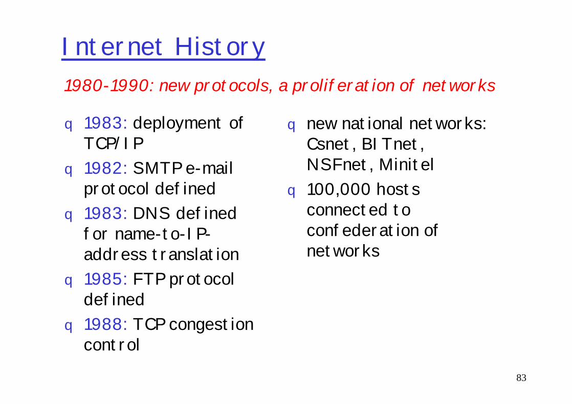
Internet History
q 1983: deployment of TCP/IP
q 1982: SMTP e-mail protocol defined 1983: DNS defined
q new national networks: Csnet, BITnet, NSFnet, Minitel
q 100,000 hosts connected to
1980-1990: new protocols, a proliferation of networks
83
q 1983: DNS defined for name-to-IP-address translation
q 1985: FTP protocol defined
q 1988: TCP congestion control
connected to confederation of networks

Internet History
q Early 1990’s: ARPAnet decommissioned
q 1991: NSF lifts restrictions on commercial use of NSFnet (decommissioned, 1995)
Late 1990’s – 2000’s:q more killer apps: instant
messaging, peer2peer file sharing (e.g., Naptser)
q network security to
1990, 2000’s: commercialization, the Web, new apps
84
(decommissioned, 1995)q early 1990s: Web
m hypertext [Bush 1945, Nelson 1960’s]
m HTML, HTTP: Berners-Leem 1994: Mosaic, later Netscapem late 1990’s:
commercialization of the Web
q network security to forefront
q est. 50 million host, 100 million+ users
q backbone links running at Gbps
q Internet-2
Roadmap
What is a Computer Network?Network ApplicationsNetwork TaxonomiesSome DefinitionsNetwork Structure: edge, core, access and media
85
Network Structure: edge, core, access and mediaInternet structure and ISPsDelay & loss in packet-switched networksProtocol layers, service modelsHistoryIP addressing and routing

IP Addressing: introductionq IP address: 32-bit
identifier for host, router interface
q interface: connection between host/router and physical link
223.1.1.1
223.1.1.2
223.1.1.3
223.1.1.4 223.1.2.9
223.1.2.2
223.1.2.1
223.1.3.27
86
and physical linkm router’s typically have
multiple interfacesm host may have multiple
interfacesm IP addresses
associated with each interface
223.1.3.2223.1.3.1
223.1.1.1 = 11011111 00000001 00000001 00000001
223 1 11

IP Addressingq IP address:
m network part (high order bits)
m host part (low order bits)
q What’s a network ?
223.1.1.1
223.1.1.2
223.1.1.3
223.1.1.4 223.1.2.9
223.1.2.2
223.1.2.1
223.1.3.27
87
q What’s a network ? (from IP address perspective)m device interfaces with
same network part of IP address
m can physically reach each other without intervening router
223.1.3.2223.1.3.1
network consisting of 3 IP networks(for IP addresses starting with 223, first 24 bits are network address)
LAN

IP AddressingHow to find the
networks?q Detach each
interface from router, host
q create “islands of
223.1.1.1
223.1.1.3
223.1.1.4
223.1.1.2
223.1.7.0223.1.9.2
88
q create “islands of isolated networks
223.1.2.2223.1.2.1
223.1.2.6
223.1.3.2223.1.3.1
223.1.3.27
223.1.7.1223.1.8.0223.1.8.1
223.1.9.1
Interconnected system consisting
of six networks

IP Addresses
0network hostA
class1.0.0.0 to127.255.255.255
given notion of “network”, let’s re-examine IP addresses:
“class-full” addressing:
89
10 network host
110 network host
1110 multicast address
B
C
D
127.255.255.255128.0.0.0 to191.255.255.255192.0.0.0 to223.255.255.255
224.0.0.0 to239.255.255.255
32 bits
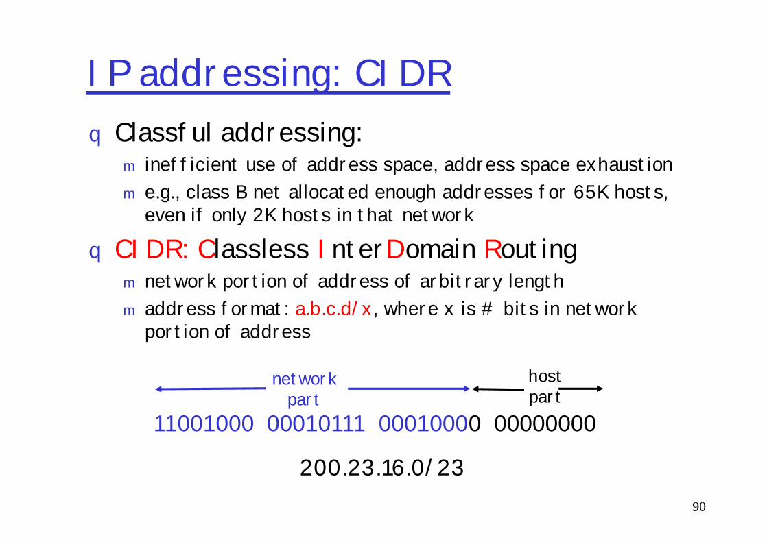
IP addressing: CIDRq Classful addressing:
m inefficient use of address space, address space exhaustionm e.g., class B net allocated enough addresses for 65K hosts,
even if only 2K hosts in that network
q CIDR: Classless InterDomain Routingnetwork portion of address of arbitrary length
90
m network portion of address of arbitrary lengthm address format: a.b.c.d/x, where x is # bits in network
portion of address
11001000 00010111 00010000 00000000
networkpart
hostpart
200.23.16.0/23

Variable Length Subnet Masks (VLSMs)q Classless routing protocols should support
advertisement of subnet informationq Can be used with RIPv2, EIGRP, or OSPF
91

IP addresses: how to get one?
Q: How does host get IP address?
q hard-coded by system admin in a filemWintel: control-panel->network->configuration-
92
mWintel: control-panel->network->configuration->tcp/ip->properties
mUNIX: /etc/rc.configq DHCP: Dynamic Host Configuration Protocol:
dynamically get address from as serverm “plug-and-play”
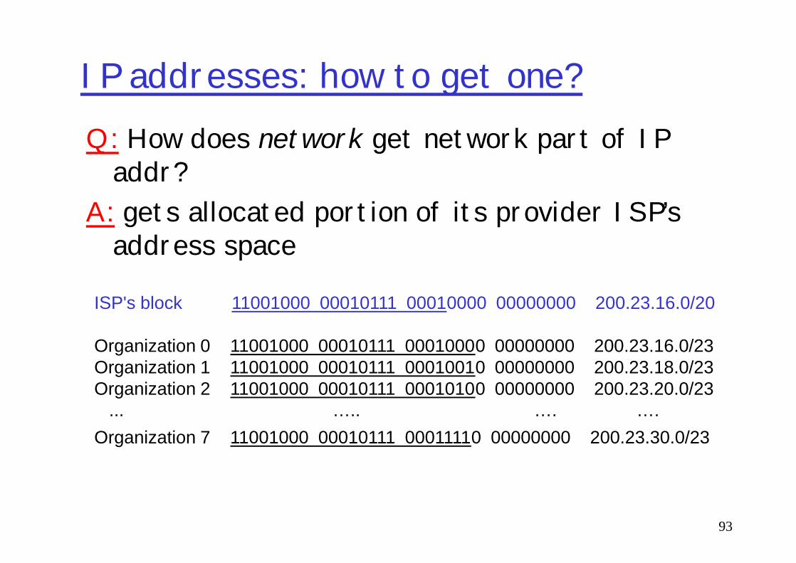
IP addresses: how to get one?Q: How does network get network part of IP
addr?A: gets allocated portion of its provider ISP’s
address space
93
ISP's block 11001000 00010111 00010000 00000000 200.23.16.0/20
Organization 0 11001000 00010111 00010000 00000000 200.23.16.0/23 Organization 1 11001000 00010111 00010010 00000000 200.23.18.0/23 Organization 2 11001000 00010111 00010100 00000000 200.23.20.0/23
... ….. …. ….Organization 7 11001000 00010111 00011110 00000000 200.23.30.0/23

Hierarchical addressing: route aggregation (aka summarization)
“Send me anything
200.23.16.0/23
200.23.18.0/23
Organization 0
Organization 1
Hierarchical addressing allows efficient advertisement of routing information:
94
“Send me anythingwith addresses beginning 200.23.16.0/20”
200.23.18.0/23
200.23.30.0/23
Fly-By-Night-ISP
Organization 7Internet
ISPs-R-Us “Send me anythingwith addresses beginning 199.31.0.0/16”
200.23.20.0/23Organization 2
...
...

Hierarchical addressing: more specific routes
ISPs-R-Us has a more specific route to Organization 1
“Send me anythingwith addresses
200.23.16.0/23Organization 0
95
with addresses beginning 200.23.16.0/20”
200.23.18.0/23
200.23.30.0/23
Fly-By-Night-ISP
Organization 7Internet
Organization 1
ISPs-R-Us “Send me anythingwith addresses beginning 199.31.0.0/16or 200.23.18.0/23”
200.23.20.0/23Organization 2
...
...

Troubleshooting IP Addressing(CISCO’s way)q ping 127.0.0.1q ping NIC's addressq ping the default gateway/ routerq ping the remote server
96
q ping the remote serverq ping user ;) if 1-4 OK.

IP addressing: the last word...
Q: How does an ISP get block of addresses?A: ICANN: Internet Corporation for Assigned
Names and Numbersm allocates addresses
97
m allocates addressesmmanages DNSm assigns domain names, resolves disputes

Getting a datagram from source to dest.
IP datagram:
223.1.1.1Amisc
fieldssourceIP addr
destIP addr data
Dest. Net. next router Nhops223.1.1 1223.1.2 223.1.1.4 2223.1.3 223.1.1.4 2
forwarding table in A
98
223.1.1.1
223.1.1.2
223.1.1.3
223.1.1.4 223.1.2.9
223.1.2.2
223.1.2.1
223.1.3.2223.1.3.1
223.1.3.27
A
BE
fields IP addr IP addr
q datagram remains unchanged, as it travels source to destination
q addr fields of interest here

Getting a datagram from source to dest.
Starting at A, send IP datagram addressed to B:
q look up net. address of B in forwarding table
Dest. Net. next router Nhops223.1.1 1223.1.2 223.1.1.4 2223.1.3 223.1.1.4 2
miscfields 223.1.1.1 223.1.1.3 data
223.1.1.1A
forwarding table in A
99
q look up net. address of B in forwarding table
q find B is on same net. as Aq link layer will send datagram
directly to B inside link-layer framem B and A are directly
connected
223.1.1.1
223.1.1.2
223.1.1.3
223.1.1.4 223.1.2.9
223.1.2.2
223.1.2.1
223.1.3.2223.1.3.1
223.1.3.27
A
BE
Getting a datagram from source to dest.
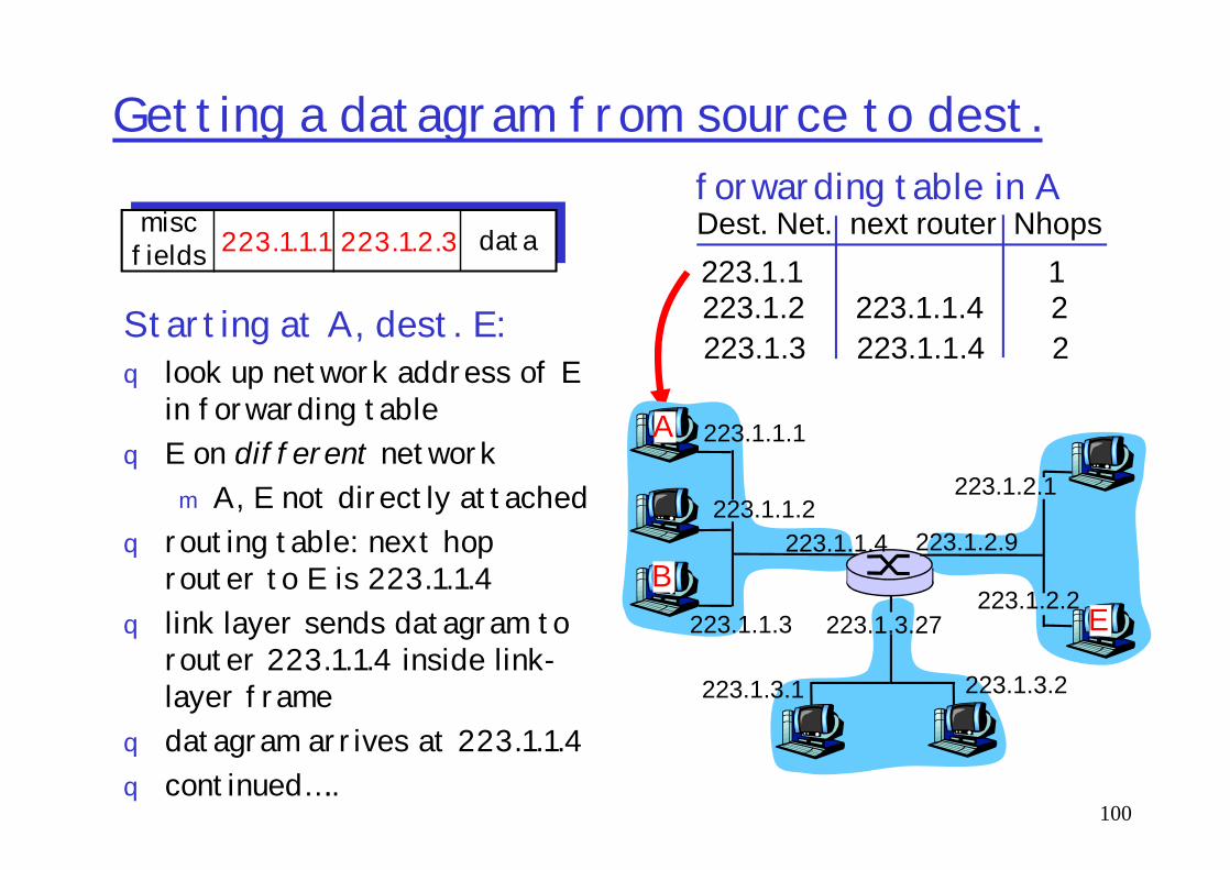
Dest. Net. next router Nhops223.1.1 1223.1.2 223.1.1.4 2223.1.3 223.1.1.4 2
Starting at A, dest. E:q look up network address of E
in forwarding tableE on different network
miscfields 223.1.1.1 223.1.2.3 data
223.1.1.1A
forwarding table in A
100
q E on different networkm A, E not directly attached
q routing table: next hop router to E is 223.1.1.4
q link layer sends datagram to router 223.1.1.4 inside link-layer frame
q datagram arrives at 223.1.1.4 q continued…..
223.1.1.1
223.1.1.2
223.1.1.3
223.1.1.4 223.1.2.9
223.1.2.2
223.1.2.1
223.1.3.2223.1.3.1
223.1.3.27
A
BE

Getting a datagram from source to dest.
Arriving at 223.1.4, destined for 223.1.2.2
q look up network address of E in router’s forwarding table
miscfields 223.1.1.1 223.1.2.3 data Dest. Net router Nhops interface
223.1.1 - 1 223.1.1.4223.1.2 - 1 223.1.2.9223.1.3 - 1 223.1.3.27
223.1.1.1A
forwarding table in router
101
look up network address of E in router’s forwarding table
q E on same network as router’s interface 223.1.2.9m router, E directly attached
q link layer sends datagram to 223.1.2.2 inside link-layer frame via interface 223.1.2.9
q datagram arrives at 223.1.2.2
223.1.1.1
223.1.1.2
223.1.1.3
223.1.1.4 223.1.2.9
223.1.2.2
223.1.2.1
223.1.3.2223.1.3.1
223.1.3.27
A
BE
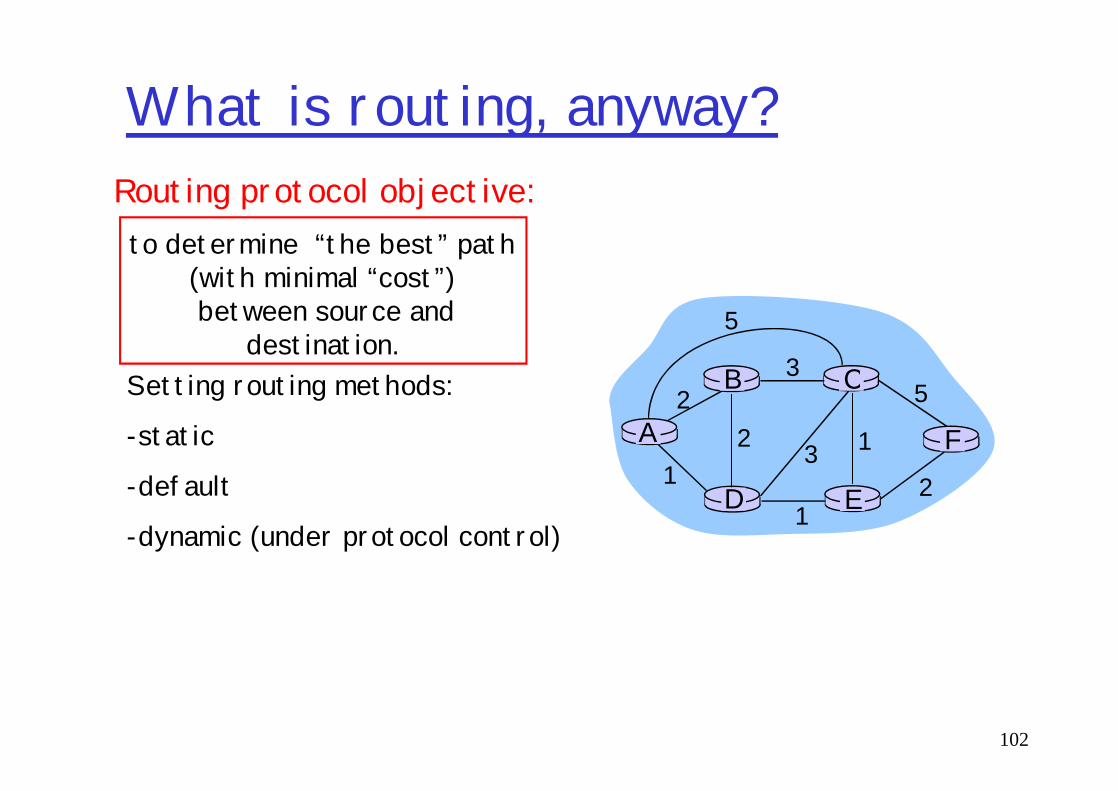
What is routing, anyway?
to determine “the best” path (with minimal “cost”)between source and
destination.CB
2 53
5
Routing protocol objective:
Setting routing methods:
102
A
ED
CB
F2
21
3
1
1
2
5Setting routing methods:
-static
-default
-dynamic (under protocol control)

Routing Algorithm classificationGlobal or decentralized
information?Global:q all routers have complete
topology, link cost infoq “link state” algorithms
Static or dynamic?Static:q routes change slowly
over timeDynamic:
103
q “link state” algorithmsDecentralized:q router knows physically-
connected neighbors, link costs to neighbors
q iterative process of computation, exchange of info with neighbors
q “distance vector” algorithms
Dynamic:q routes change more
quicklym periodic updatem in response to link
cost changes

IP datagram format
ver length
32 bits
16-bit identifierInternetchecksum
time tolive
32 bit source IP address
IP protocol versionnumber
header length(bytes)
max numberremaining hops
(decremented at each router)
forfragmentation/reassembly
total datagramlength (bytes)head.
lentype ofservice
“type” of data flgs fragmentoffset
upperlayer
104
data (variable length,typically a TCP
or UDP segment)
32 bit source IP addresseach router)
upper layer protocolto deliver payload to
32 bit destination IP address
Options (if any) E.g. timestamp,record routetaken, specifylist of routers to visit.
how much overhead with TCP?
q 20 bytes of TCPq 20 bytes of IPq = 40 bytes + app
layer overhead
Internet Routing
105
scale: with 200 million destinations:
q can’t store all dest’s in routing tables!
q routing table exchange would swamp links!
administrative autonomyq internet = network of
networksq each network admin may
want to control routing in its own network
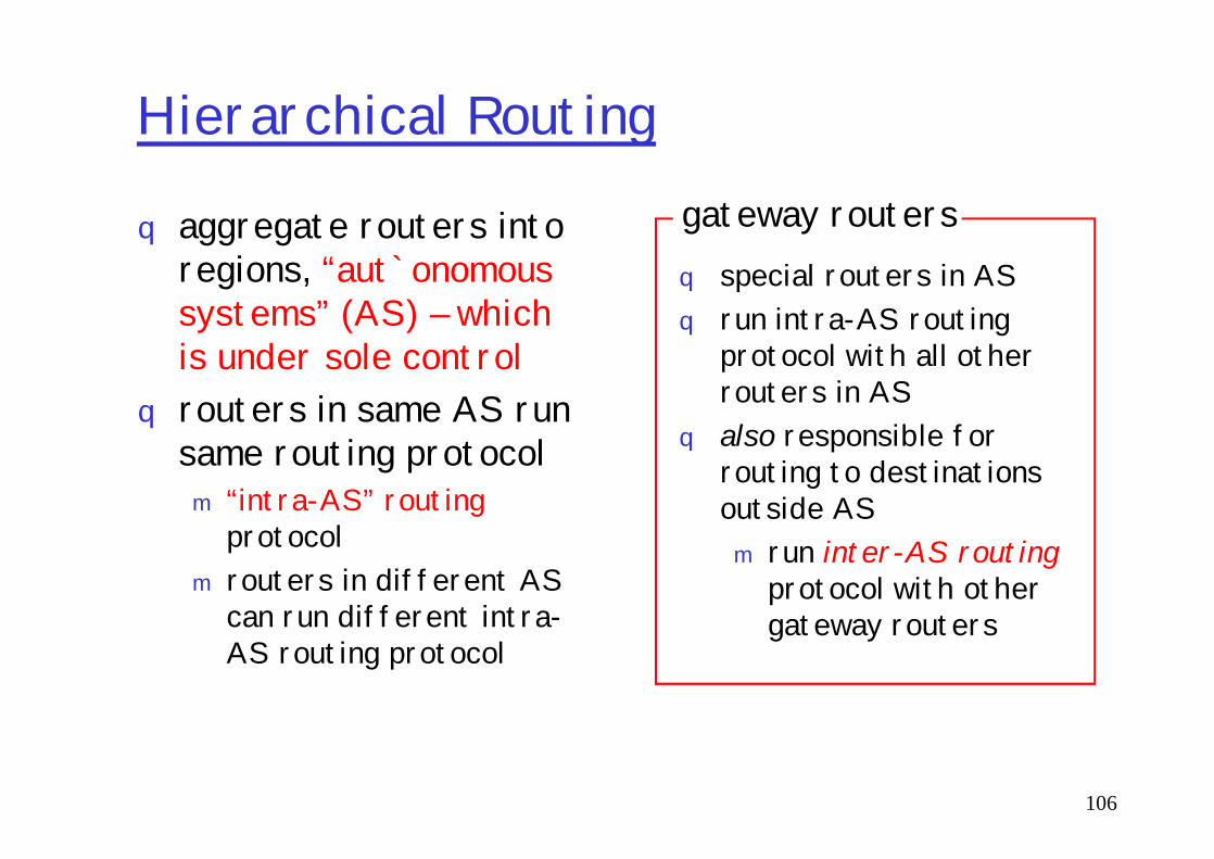
Hierarchical Routing
q aggregate routers into regions, “aut`onomous systems” (AS) – which is under sole control
q routers in same AS run same routing protocol
q special routers in ASq run intra-AS routing
protocol with all other routers in AS
q also responsible for
gateway routers
106
routers in same AS run same routing protocolm “intra-AS” routing
protocolm routers in different AS
can run different intra-AS routing protocol
q also responsible for routing to destinations outside ASm run inter-AS routing
protocol with other gateway routers

Intra-AS and Inter-AS routing
Host h2
ab
aaC
B
A.aA.c
C.bB.a
cb
Host
Inter-ASroutingbetween A and B
107
b
a
A
Bd c
Hosth1
Intra-AS routingwithin AS A
Intra-AS routingwithin AS B
q We’ll examine specific inter-AS and intra-AS Internet routing protocols shortly

Routing in the Internetq The Global Internet consists of Autonomous Systems
(AS) interconnected with each other:m Stub AS: small corporation: one connection to other AS’sm Multihomed AS: large corporation (no transit): multiple
connections to other AS’sm Transit AS: provider, hooking many AS’s together
108
m Transit AS: provider, hooking many AS’s together
q Two-level routing: m Intra-AS: administrator responsible for choice of routing
algorithm within networkm Inter-AS: unique standard for inter-AS routing: BGP
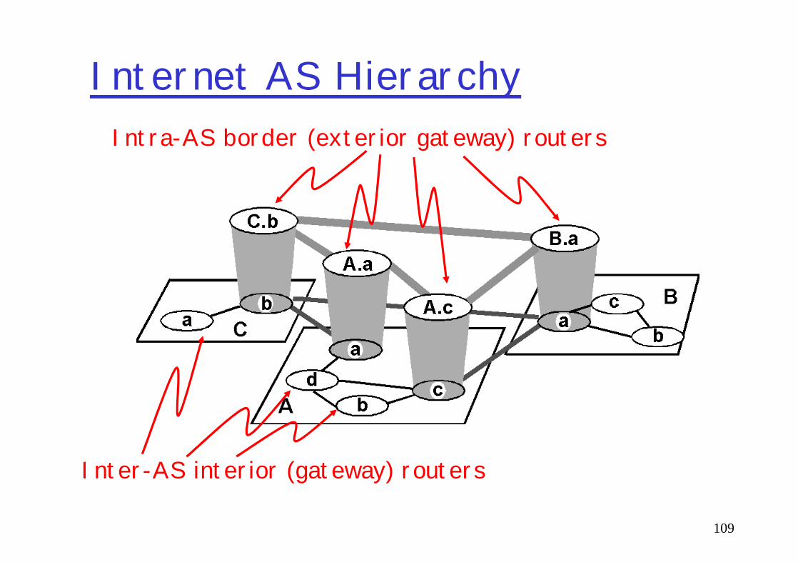
Internet AS HierarchyIntra-AS border (exterior gateway) routers
109
Inter-AS interior (gateway) routers

Internet AS HierarchyInternet backbone
110
Autonomous System N

Intra-AS Routing
q Also known as Interior Gateway Protocols (IGP)q Most common Intra-AS routing protocols:
m RIP(1,2): Routing Information Protocol
mOSPF: Open Shortest Path First
111
mOSPF: Open Shortest Path First
m (E)IGRP: Interior Gateway Routing Protocol (Cisco proprietary)

RIP ( Routing Information Protocol)
q Distance vector algorithmq Included in BSD-UNIX Distribution in 1982q Distance metric: # of hops (max = 15 hops)q Distance vectors: exchanged among neighbors every
30 sec via Response Message (also called
112
30 sec via Response Message (also called advertisement)
q Each advertisement: list of up to 25 destination nets within AS

OSPF (Open Shortest Path First)
q “open”: publicly availableq Uses Link State algorithm
m LS packet disseminationm Topology map at each nodem Route computation using Dijkstra’s algorithm
113
q OSPF advertisement carries one entry per neighbor router
q Advertisements disseminated to entire AS (via flooding)m Carried in OSPF messages directly over IP (rather than TCP
or UDP
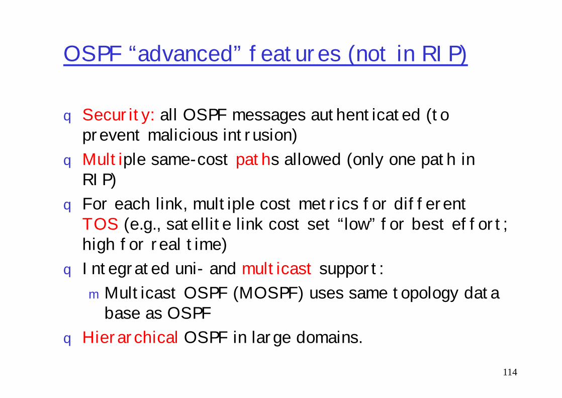
OSPF “advanced” features (not in RIP)
q Security: all OSPF messages authenticated (to prevent malicious intrusion)
q Multiple same-cost paths allowed (only one path in RIP)
q For each link, multiple cost metrics for different
114
q For each link, multiple cost metrics for different TOS (e.g., satellite link cost set “low” for best effort; high for real time)
q Integrated uni- and multicast support: mMulticast OSPF (MOSPF) uses same topology data
base as OSPFq Hierarchical OSPF in large domains.

Inter-AS routing in the Internet: BGP
AS2 (OSPF
intra-AS routing)
AS1 (RIP intra-AS
routing) BGP
AS3 (OSPF intra-AS
routing)
BGP
R3
R4
R5
115
Figure 4.5.2-new2: BGP use for inter-domain routing
routing)
R1 R2

Internet inter-AS routing: BGP
q BGP (Border Gateway Protocol): the de facto standard
q Path Vector protocol:m similar to Distance Vector protocolm each Border Gateway broadcast to neighbors
116
m each Border Gateway broadcast to neighbors (peers) entire path (i.e., sequence of AS’s) to destination
m BGP routes to networks (ASs), not individual hosts
NAT: Network Address Translation
10.0.0.1
10.0.0.210.0.0.4
138.76.29.7
local network(e.g., home network)
10.0.0/24
rest ofInternet
117
10.0.0.3
138.76.29.7
Datagrams with source or destination in this networkhave 10.0.0/24 address for source, destination (as usual)
All datagrams leaving localnetwork have same single source
NAT IP address: 138.76.29.7,different source port numbers
NAT: Network Address Translation
q Motivation: local network uses just one IP address as far as outside word is concerned:m no need to be allocated range of addresses from ISP:
- just one IP address is used for all devicesm can change addresses of devices in local network
118
m can change addresses of devices in local network without notifying outside world
m can change ISP without changing addresses of devices in local network
m devices inside local net not explicitly addressable, visible by outside world (a security plus).

NAT: Network Address Translation
qNAT is controversial:m routers should only process up to layer 3m violates end-to-end argument
• NAT possibility must be taken into account by app designers, eg, P2P applications
119
designers, eg, P2P applicationsm address shortage should instead be solved by
IPv6

ICMP: Internet Control Message Protocol
q used by hosts & routers to communicate network-level informationm error reporting:
unreachable host, network, port, protocolecho request/reply (used
Type Code description0 0 echo reply (ping)3 0 dest. network unreachable3 1 dest host unreachable3 2 dest protocol unreachable3 3 dest port unreachable
120
m echo request/reply (used by ping)
q network-layer “above” IP:m ICMP msgs carried in IP
datagramsq ICMP message: type, code plus
first 8 bytes of IP datagram causing error
3 3 dest port unreachable3 6 dest network unknown3 7 dest host unknown4 0 source quench (congestion
control - not used)8 0 echo request (ping)9 0 route advertisement10 0 router discovery11 0 TTL expired12 0 bad IP header

IPv6q Initial motivation: 32-bit address space soon?
to be completely allocated, problems in China.qAdditional motivation:m header format helps speed processing/forwardingm header changes to facilitate QoS
121
m header changes to facilitate QoS IPv6 datagram format:m fixed-length 40 byte headerm no fragmentation allowed
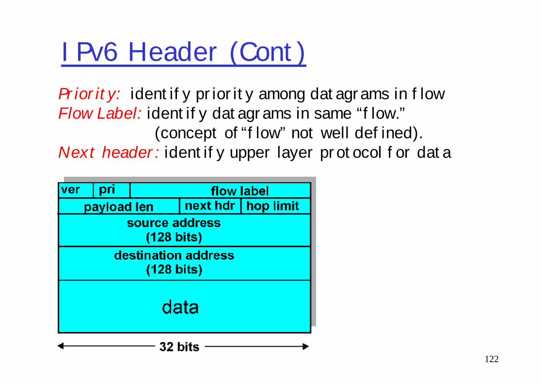
IPv6 Header (Cont)Priority: identify priority among datagrams in flowFlow Label: identify datagrams in same “flow.”
(concept of“flow” not well defined).Next header: identify upper layer protocol for data
122

Other Changes from IPv4
q Checksum: removed entirely to reduce processing time at each hop
qOptions: allowed, but outside of header, indicated by “Next Header” field
123
indicated by “Next Header” fieldq ICMPv6: new version of ICMPm additional message types, e.g. “Packet Too Big”mmulticast group management functions
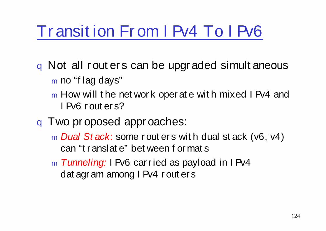
Transition From IPv4 To IPv6
qNot all routers can be upgraded simultaneousm no “flag days”mHow will the network operate with mixed IPv4 and
IPv6 routers? Two proposed approaches:
124
q Two proposed approaches:m Dual Stack: some routers with dual stack (v6, v4)
can “translate” between formatsm Tunneling: IPv6 carried as payload in IPv4
datagram among IPv4 routers
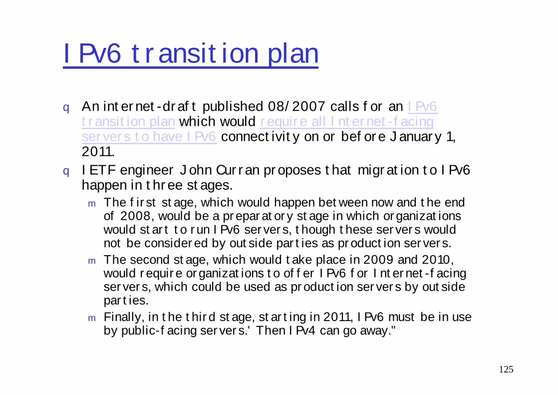
IPv6 transition plan q An internet-draft published 08/2007 calls for an IPv6
transition plan which would require all Internet-facing servers to have IPv6 connectivity on or before January 1, 2011.
q IETF engineer John Curran proposes that migration to IPv6 happen in three stages.
The first stage, which would happen between now and the end
125
m The first stage, which would happen between now and the end of 2008, would be a preparatory stage in which organizations would start to run IPv6 servers, though these servers would not be considered by outside parties as production servers.
m The second stage, which would take place in 2009 and 2010, would require organizations to offer IPv6 for Internet-facing servers, which could be used as production servers by outside parties.
m Finally, in the third stage, starting in 2011, IPv6 must be in use by public-facing servers.' Then IPv4 can go away."

Dual Stack Approach
A B E F
IPv6 IPv6 IPv6 IPv6
C D
IPv4 IPv4
Flow: XSrc: ADest: F
Flow: ??Src: ADest: F
Src:ADest: F
Src:ADest: F
126
data datadata
A-to-B:IPv6
data
B-to-C:IPv4
B-to-C:IPv4
B-to-C:IPv6

TunnelingA B E F
IPv6 IPv6 IPv6 IPv6
tunnelLogical view:
A B E F
IPv6 IPv6 IPv6 IPv6
C D
IPv4 IPv4
Flow: X Flow: XSrc:B Src:B
127
Implementation view:
Flow: XSrc: ADest: F
data
Flow: XSrc: ADest: F
data
Flow: XSrc: ADest: F
data
Src:BDest: E
Flow: XSrc: ADest: F
data
Src:BDest: E
A-to-B:IPv6
E-to-F:IPv6B-to-C:
IPv6 insideIPv4
B-to-C:IPv6 inside
IPv4

Network layer service models:
NetworkArchitecture
Internet
ATM
ServiceModel
best effort
CBR
Bandwidth
none
constantrate
Loss
no
yes
Order
no
yes
Timing
no
yes
Congestionfeedback
no (inferredvia loss)nocongestion
Guarantees ?
128
ATM
ATM
ATM
VBR(rt,nrt)
ABR
UBR
rateguaranteedrateguaranteed minimumnone
yes
no
no
yes
yes
yes
yes
no
no
congestionnocongestionyes
no
q Internet model being extended: Intserv, Diffservq Note: C=constant, U=unspecified, A=available, V=variable

Introduction: SummaryCovered a “ton” of material!q Network taxonomiesq Basic definitionsq Network structure: edge,
core, access packet-switching versus
You now have:q context, overview,
“feel” of networkingq more depth, detail to
follow!
129
m packet-switching versus circuit-switching
q Internet/ISP/AS structureq performance: loss, delayq layering and service modelsq historyq IP addressing and routing

Dynamic Routing
q Routing Protocol finds networks and updatesrouting table on router.
q The Administrative Distance (AD) is used to rate the level of trust of routing information received on a router from a neighbor router.
130
on a router from a neighbor router.q After receiving updates, the router will place in
IP-table the route with lowest AD, if ADs are equal, with lowest metric (route’s quality).
q In case of equal metrics and ADs à router performs load ballancing.
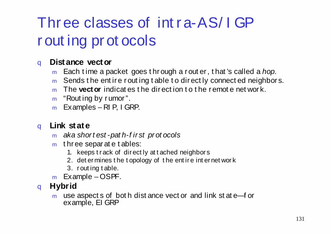
Three classes of intra-AS/IGP routing protocolsq Distance vector
m Each time a packet goes through a router, that’s called a hop.m Sends the entire routing table to directly connected neighbors.m The vector indicates the direction to the remote network.m “Routing by rumor”.m Examples – RIP, IGRP.
131
q Link statem aka shortest-path-first protocolsm three separate tables:
1. keeps track of directly attached neighbors2. determines the topology of the entire internetwork3. routing table.
m Example – OSPF.q Hybrid
m use aspects of both distance vector and link state—for example, EIGRP

Distance-vector routing
132
converged
Starting …

Routing loop
1. Network 5 fails, Router E tells Router C2. Router C to stop routing to Network5 through Router E
133
1. Network 5 fails, Router E tells Router C2. Router C to stop routing to Network5 through Router E3. But Routers A, B, D don’t know about Network 5 yet and keep sending updates4. Router C will eventually send out its update and cause B to stop routing to Network
5, but Routers A and D are still not updated. To them, it appears that Network 5 is still available through Router B with a metric of 3.
5. The problem occurs when Router A sends out its regular 30-second update message, which includes the ability to reach Network 5 and now Routers B and D receive the news that Network 5 can be reached from Router A, so Routers B and D then send out the information that Network 5 is available. Any packet destined for Network 5 will go to Router A, to Router B, and then back to Router A.
Routing loop 2
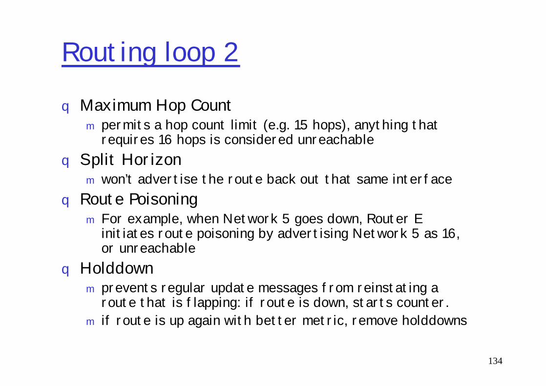
q Maximum Hop Countm permits a hop count limit (e.g. 15 hops), anything that
requires 16 hops is considered unreachableq Split Horizon
m won’t advertise the route back out that same interfaceq Route Poisoning
134
q Route Poisoningm For example, when Network 5 goes down, Router E
initiates route poisoning by advertising Network 5 as 16, or unreachable
q Holddownm prevents regular update messages from reinstating a
route that is flapping: if route is down, starts counter.m if route is up again with better metric, remove holddowns

RIPq Open standardq maximum allowable hop count of 15q Versions: – RIP1, RIP2, RIPngq AD=120q Can perform load balancing for up to six equal-cost links
(four by default)q version RIPng supports IPv6
Version 2 similar to version 1, but in addition:
135
version RIPng supports IPv6q Version 2 similar to version 1, but in addition:
m sends subnet mask information with the route updates – can be considered as classless routing protocol,
m can support VLSMs andm summarization of network boundaries,m authentication,m uses multicast instead of ver.1 broadcastsm can support discontiguous networking.
q Aka R.I.P.

RIP timersq Route update timer
m Sets the interval (typically 30 seconds) between periodic routing updates, in which the router sends a complete copy of its routing table out to all neighbors.
q Route invalid timerm Determines the length of time that must elapse (180 seconds) before a
router determines that a route has become invalid. It will come to this conclusion if it hasn’t heard any updates about a particular route for that period. When that happens, the router will send out updates to all its neighbors letting them know that the route is invalid.
136
its neighbors letting them know that the route is invalid.q Holddown timer
m This sets the amount of time during which routing information is suppressed. The default is 180 seconds.
q Route flush timer m Sets the time between a route becoming invalid and its removal from
the routing table (240 seconds). Before it’s removed from the table, the router notifies its neighbors of that route’s impending demise. The value of the route invalid timer must be less than that of the route flush timer.
q RIP can perform load balancing for up to six equal-cost links (four by default)

Configuring RIPLab(config)#router ripLab(config-router)#network 192.168.20.0Lab(config-router)#network 192.168.30.0Lab(config-router)#network 192.168.40.0Lab(config-router)#network 192.168.50.0?Lab(config-router)#version 2?Lab(config-router)#passive-interface serial 0/1Lab(config-router)#^Z
137
Lab(config-router)#^ZLab#
Lab#sh ip route[...]R 192.168.30.0 [120/1] via 192.168.40.1, 00:00:04, Serial0/0Q: what's wrong?
show ip protocoldebug ip rip

Interior Gateway Routing Protocol (IGRP)
138
Replacement is Enhanced IGRP (EIGRP)IGRP can load-balance up to 6 unequal links, uses bandwidth to determine how to load-balance. To load-balance over unequal-cost links, the variance command controls the load balancing between the best metric and the worst acceptable metric.Note: Reliability, load, and maximum transmission unit (MTU) can also be used to calculate composite metric, although they are not used by default.
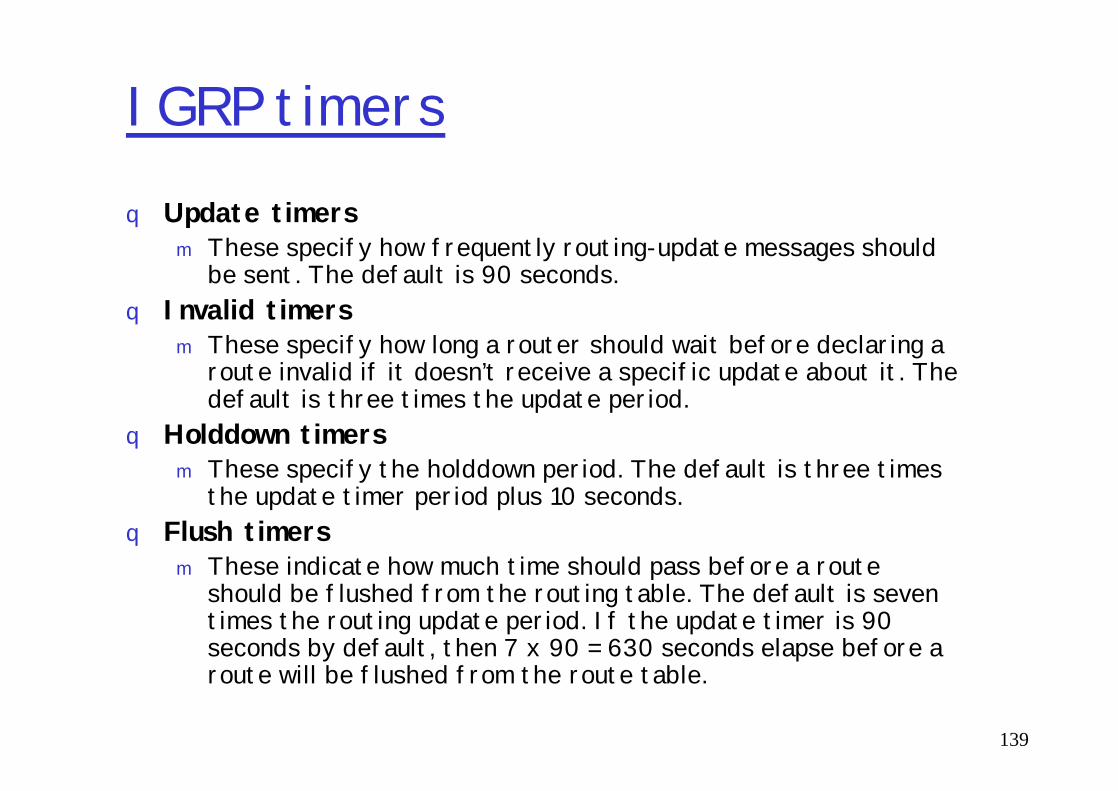
IGRP timersq Update timers
m These specify how frequently routing-update messages should be sent. The default is 90 seconds.
q Invalid timersm These specify how long a router should wait before declaring a
route invalid if it doesn’t receive a specific update about it. The default is three times the update period.
139
default is three times the update period.q Holddown timers
m These specify the holddown period. The default is three times the update timer period plus 10 seconds.
q Flush timersm These indicate how much time should pass before a route
should be flushed from the routing table. The default is seven times the routing update period. If the update timer is 90seconds by default, then 7 x 90 = 630 seconds elapse before a route will be flushed from the route table.

Configuring IGRPLab#config tLab(config)#router igrp 10Lab(config-router)#netw 192.168.10.0Lab(config-router)#netw 192.168.20.0Lab(config-router)#^ZLab#
Lab#sh ip route
140
Lab#sh ip route[…]C 192.168.50.0 is directly connected, FastEthernet 0/0C 192.168.40.0 is directly connected, Serial0/0I 192.168.30.0 [100/143723] via 192.168.40.1, 00:00:42, Serial0/0I 192.168.20.0 [100/152365] via 192.168.40.1, 00:00;52, Serial0/0I 192.168.10.0 [100/158350] via 192.168.20.1, 00:00:36, Serial0/0Lab_C#Note: 158350 – composite metric
debug ip igrp eventsdebug ip igrp transactionsundebug all
Enhanced IGRP (EIGRP)
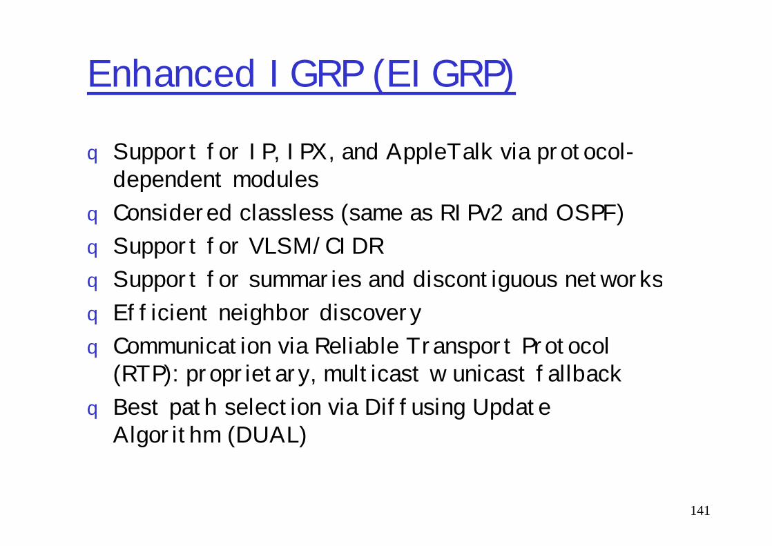
q Support for IP, IPX, and AppleTalk via protocol-dependent modules
q Considered classless (same as RIPv2 and OSPF) q Support for VLSM/CIDRq Support for summaries and discontiguous networks
141
q Support for summaries and discontiguous networksq Efficient neighbor discoveryq Communication via Reliable Transport Protocol
(RTP): proprietary, multicast w unicast fallbackq Best path selection via Diffusing Update
Algorithm (DUAL)

Neighbor Discovery
q neighborship (aka adjacencies) establishment:mHello or ACK receivedm AS numbers matchm Identical metrics (K values)
to maintain the neighborship relationship,
142
q to maintain the neighborship relationship, EIGRP routers must also continue receiving Hellos from their neighbors.
q IGRP advertises its entire routing table only when it discovers a new neighbor and forms an adjacency
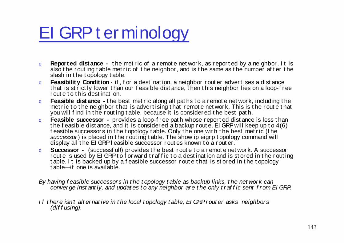
EIGRP terminologyq Reported distance - the metric of a remote network, as reported by a neighbor. It is
also the routing table metric of the neighbor, and is the same as the number after the slash in the topology table.
q Feasibility Condition - if, for a destination, a neighbor router advertises a distance that is strictly lower than our feasible distance, then this neighbor lies on a loop-free route to this destination.
q Feasible distance -the best metric along all paths to a remote network, including the metric to the neighbor that is advertising that remote network. This is the route that you will find in the routing table, because it is considered the best path.
q Feasible successor - provides a loop-free path whose reported distance is less than the feasible distance, and it is considered a backup route. EIGRP will keep up to 4(6)
143
q Feasible successor - provides a loop-free path whose reported distance is less than the feasible distance, and it is considered a backup route. EIGRP will keep up to 4(6) feasible successors in the topology table. Only the one with the best metric (the successor) is placed in the routing table. The show ip eigrp topology command will display all the EIGRP feasible successor routes known to a router.
q Successor - (successful!) provides the best route to a remote network. A successor route is used by EIGRP to forward traffic to a destination and is stored in the routing table. It is backed up by a feasible successor route that is stored in the topology table—if one is available.
By having feasible successors in the topology table as backup links, the network can converge instantly, and updates to any neighbor are the only traffic sent from EIGRP.
If there isn’t alternative in the local topology table, EIGRP router asks neighbors (diffusing).
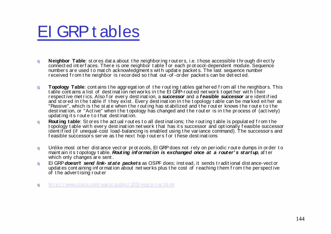
EIGRP tablesq Neighbor Table: stores data about the neighboring routers, i.e. those accessible through directly
connected interfaces. There is one neighbor table for each protocol-dependent module. Sequence numbers are used to match acknowledgments with update packets. The last sequence number received from the neighbor is recorded so that out-of-order packets can be detected.
q Topology Table: contains the aggregation of the routing tables gathered from all the neighbors. This table contains a list of destination networks in the EIGRP-routed network together with their respective metrics. Also for every destination, a successor and a feasible successor are identified and stored in the table if they exist. Every destination in the topology table can be marked either as "Passive", which is the state when the routing has stabilized and the router knows the route to the destination, or "Active" when the topology has changed and the router is in the process of (actively) updating its route to that destination.
144
updating its route to that destination. q Routing table: Stores the actual routes to all destinations; the routing table is populated from the
topology table with every destination network that has its successor and optionally feasible successor identified (if unequal-cost load-balancing is enabled using the variance command). The successors and feasible successors serve as the next hop routers for these destinations
q Unlike most other distance vector protocols, EIGRP does not rely on periodic route dumps in order to maintain its topology table. Routing information is exchanged once at a router's startup, after which only changes are sent.
q EIGRP doesn’t send link-state packets as OSPF does; instead, it sends traditional distance-vector updates containing information about networks plus the cost of reaching them from the perspective of the advertising router
q http://www.cisco.com/warp/public/103/eigrp-toc.html

EIGRP metric
q bandwidth = 10000000/bandwidth(Kbps))q delay = delay(mks)
Default K values: K1=1; K2=0; K3=1; K4=0; K5=0, hence
145
q Default K values: K1=1; K2=0; K3=1; K4=0; K5=0, hence metric = 256*(bandwidth + delay)
q Reliability’s range [1..255], 255 – most reliableq Load belongs to range [1..255], 255 - saturated
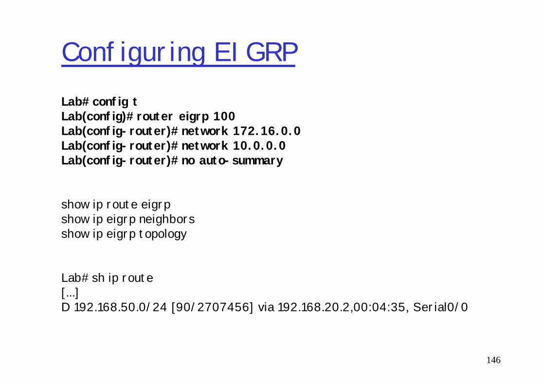
Configuring EIGRPLab#config tLab(config)#router eigrp 100Lab(config-router)#network 172.16.0.0Lab(config-router)#network 10.0.0.0Lab(config-router)#no auto-summary
146
show ip route eigrpshow ip eigrp neighborsshow ip eigrp topology
Lab#sh ip route[...]D 192.168.50.0/24 [90/2707456] via 192.168.20.2,00:04:35, Serial0/0
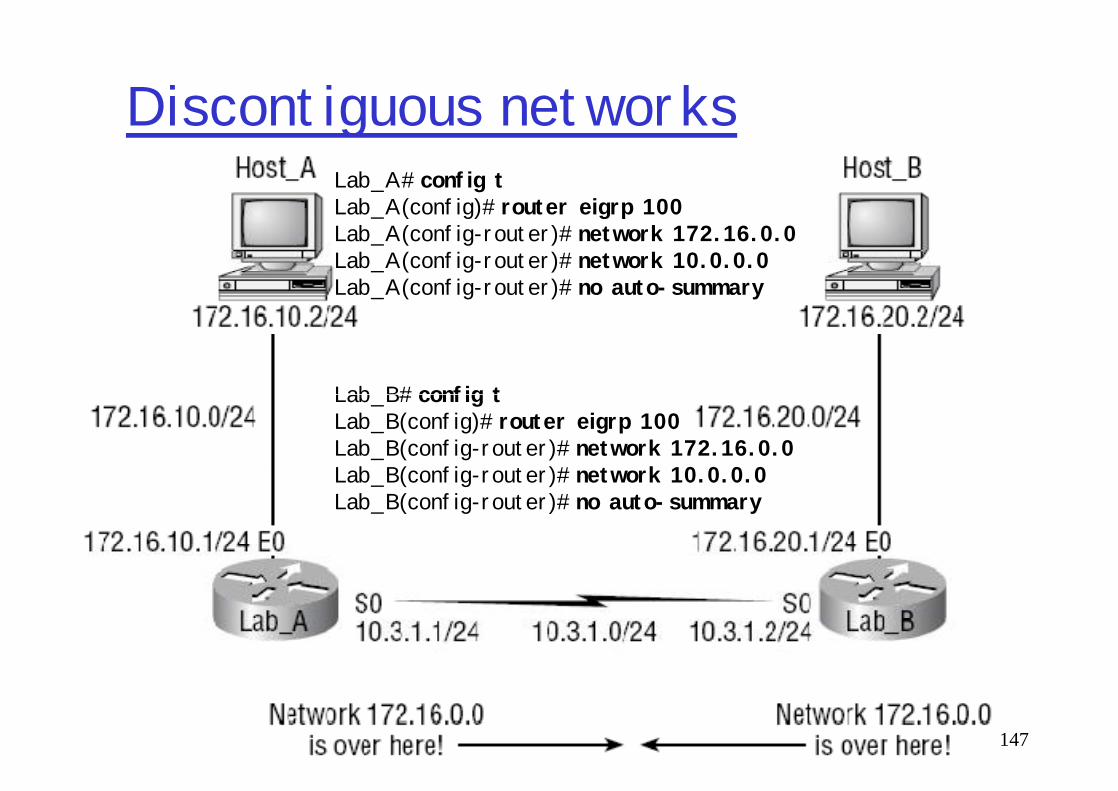
Discontiguous networksLab_A#config tLab_A(config)#router eigrp 100Lab_A(config-router)#network 172.16.0.0Lab_A(config-router)#network 10.0.0.0Lab_A(config-router)#no auto-summary
Lab_B#config t
147
Lab_B#config tLab_B(config)#router eigrp 100Lab_B(config-router)#network 172.16.0.0Lab_B(config-router)#network 10.0.0.0Lab_B(config-router)#no auto-summary
Redistribution
q Routes originated within a specific AS in IGRP are called internal EIGRP route
q External EIGRP routes (AD=170) appear within EIGRP route tables courtesy of either manual or automatic redistribution, and they represent
148
automatic redistribution, and they represent networks that originated outside of the EIGRP autonomous system
q If the same AS number set for EIGRP that used for IGRP, EIGRP will automatically redistribute the routes from IGRP into EIGRP with AD=170
Configuring EIGRP andOSPF Summary Routes
149
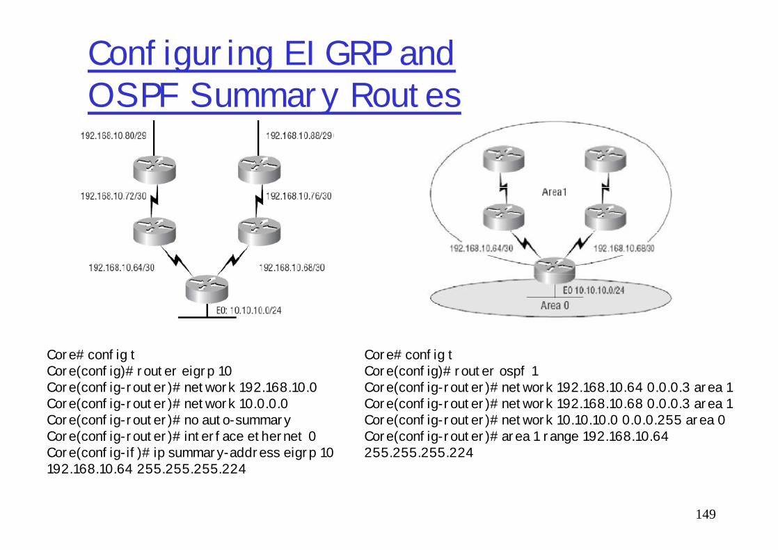
Core#config tCore(config)#router eigrp 10Core(config-router)#network 192.168.10.0Core(config-router)#network 10.0.0.0Core(config-router)#no auto-summaryCore(config-router)#interface ethernet 0Core(config-if)#ip summary-address eigrp 10 192.168.10.64 255.255.255.224
Core#config tCore(config)#router ospf 1Core(config-router)#network 192.168.10.64 0.0.0.3 area 1Core(config-router)#network 192.168.10.68 0.0.0.3 area 1Core(config-router)#network 10.10.10.0 0.0.0.255 area 0Core(config-router)#area 1 range 192.168.10.64 255.255.255.224
Open Shortest Path First (OSPF)
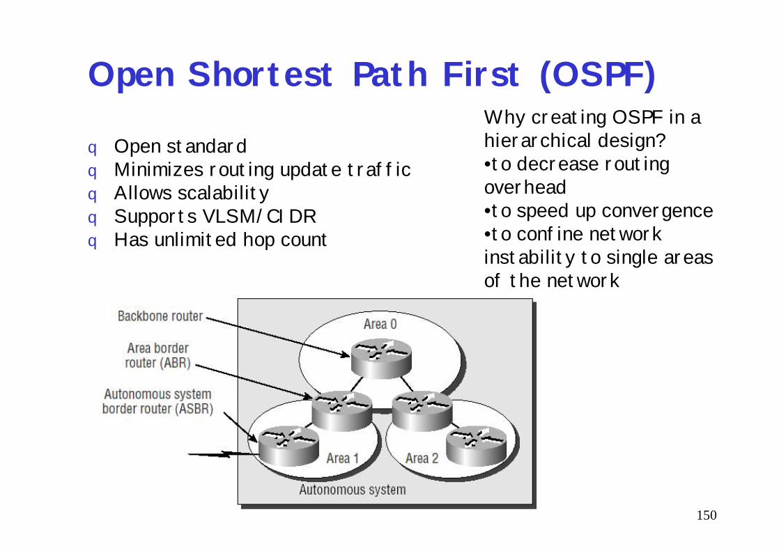
q Open standardq Minimizes routing update trafficq Allows scalabilityq Supports VLSM/CIDRq Has unlimited hop count
Why creating OSPF in a hierarchical design?•to decrease routing overhead•to speed up convergence•to confine network instability to single areas of the network
150
of the network

Open Shortest Path First (OSPF)2q Routers in the same broadcast domain or at each
end of a point-to-point telecommunications link form adjacencies when they have detected each other, when "see" itselfs in a hello packets.
q OSPF uses both unicast and multicast to send "hello packets" and link state updates. Multicast addresses 224.0.0.5 (all SPF/link state routers)
151
"hello packets" and link state updates. Multicast addresses 224.0.0.5 (all SPF/link state routers) and 224.0.0.6 (all Designated Routers) are reserved for OSPF. OSPF does not use TCP or UDP but uses IP directly
q The routers elect a designated router (DR) and a backup designated router (BDR) which act as a hub to reduce traffic between routers in case of broadcast network. BDR, DR are not used in P2P.

OSPF vs RIP
152
OSPF terminologyq Router ID (RID) - is an IP address used to identify the router.
Cisco chooses the RID by using the highest IP address of all configured loopback interfaces. If no loopback interfaces are configured with addresses, OSPF will choose the highest IP address of all active physical interfaces.
q Adjacency - is a relationship between two routers that permits the direct exchange of route updates. And not all neighbors will become adjacent—this depends upon both the type of network and the configuration of the routers.
153
adjacent—this depends upon both the type of network and the configuration of the routers.
q Link State Advertisement (LSA) - is an OSPF data packet containing link-state and routing information that’s shared among OSPF routers.
q Hello protocol - provides dynamic neighbor discovery and maintains neighbor relationships. Hello packets and Link State Advertisements (LSAs) build and maintain the topological database. Hello packets are addressed to 224.0.0.5.
q Area - is a grouping of contiguous networks and routers. All routers in the same area share a common Area ID. Because a router can be a member of more than one area at a time, the Area ID is associated with specific interfaces on the router.
OSPF databases
q Neighborship database - is a list of all OSPF routers for which Hello packets have been seen. A variety of details, including the RID and state, are maintained on each router in the neighborship database.
154
database.q Topology database - contains information from all
of the Link State Advertisement packets that have been received for an area. The router uses the information from the topology database as input into the Dijkstra algorithm that computes the shortest path to every network.

OSPF
q each router calculates the best/shortest path to every network in that same area forming a tree. This calculation is based upon the information collected in the topology database and an algorithm called
155
topology database and an algorithm called shortest path first (SPF).
qOSPF uses a metric referred to as cost -which is associated with every outgoing interface included in an SPF tree.
q CISCO’s OSPF cost=108/bandwidth

Configuring OSPF
qDisabling protocols with higher ADm Lab(config)#no router eigrp 10m Lab(config)#no router igrp 10
q Enabling OSPF (PID is locally significant)
156
q Enabling OSPF (PID is locally significant)m Lab(config)#router ospf ?m <1-65535>m Lab(config)#router ospf 1
q Configuring OSPF areasm network 10.0.0.0 0.255.255.255 area 0

Configuring OSPF 2Lab#config tLab(config)#router ospf 64999Lab(config-router)#network 192.168.40.0 0.0.0.255 area 0Lab(config-router)#network 192.168.50.0 0.0.0.255 area 0Lab(config-router)#^ZLab#
show ip ospfshow ip ospf database
157
show ip ospf databaseshow ip ospf interface
shows: IP, Area assignment, Process ID, RID, Network type, Cost, Priority, DR/BDR election information (if applicable), Hello and Dead timer intervals, Adjacent neighbor information
show ip ospf neighborshow ip protocols
Lab#sh ip route[…]O 192.168.30.0/24 [110/65] via 192.168.20.2, 00:01:07, Serial0/0
Configuring Loopback Interfaces
Lab#config tLab(config)#int loopback 0Lab(config-if)#ip address 172.16.10.1 255.255.255.255Lab(config-if)#no shutLab(config-if)#^ZLab#
158
Lab#
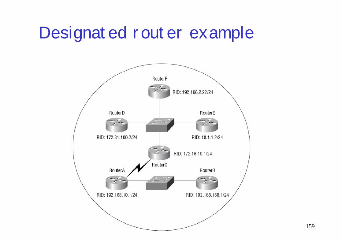
Designated router example
159

AD’s values
160

Inter-AS routing in the Internet: BGP
AS2 (OSPF
intra-AS routing)
AS1 (RIP intra-AS
routing) BGP
AS3 (OSPF intra-AS
routing)
BGP
R3
R4
R5
161
Figure 4.5.2-new2: BGP use for inter-domain routing
routing)
R1 R2
Substitution of EGP
Since 1994, version 4 of the protocol has been in use on the Internet

Internet inter-AS routing: BGP
q BGP (Border Gateway Protocol): the de facto standard
q Path Vector protocol:m similar to Distance Vector protocolm each Border Gateway broadcast to neighbors
162
m each Border Gateway broadcast to neighbors (peers) entire path (i.e., sequence of AS’s) to destination
m BGP routes to ASs networks , not individual hosts
m E.g., Gateway X may send its path to dest. Z:
Path (X,Z) = X,Y1,Y2,Y3,…,Z

Internet inter-AS routing: BGP
Suppose: gateway X send its path to peer gateway Wq W may or may not select path offered by Xm cost, policy (don’t route via competitors AS), loop
prevention reasons.q If W selects path advertised by X, then:
163
q If W selects path advertised by X, then:Path (W,Z) = x, Path (X,Z)
q Note: X can control incoming traffic by controlling it route advertisements to peers:m e.g., don’t want to route traffic to Z -> don’t
advertise any routes to Z

BGP: controlling who routes to you
A
B
C
W X
Y
legend:
customer network:
provider network
164
Figure 4.5-BGPnew: a simple BGP scenario q A,B,C are backbone provider networksq X,W,Y are customers networksq X is dual-homed: attached to two networksm X does not want to route from B via X to Cm .. so X will not advertise to B a route to C

BGP: controlling who routes to you
A
B
C
W X
Y
legend:
customer network:
provider network
165
Figure 4.5-BGPnew: a simple BGP scenario q A advertises to B the path AW q B advertises to X the path BAW q Should B advertise to C the path BAW?
m No. B gets no “revenue” for routing CBAW since neither W nor C are B’s customers
m B wants to force C to route to w via Am B wants to route only to/from its customers!

BGP operation
Q: What does a BGP router do?q Receiving and filtering route advertisements from
directly attached neighbor(s). q Route selection.
To route to destination X, which path )of
166
m To route to destination X, which path )of several advertised) will be taken?
q Sending route advertisements to neighbors.

BGP messages
q BGP messages exchanged using TCP port=179.q BGP messages:mOPEN: opens TCP connection to peer and
authenticates sendermUPDATE: advertises new path (or withdraws old)
167
mUPDATE: advertises new path (or withdraws old)m KEEPALIVE keeps connection alive in absence of
UPDATES; also ACKs OPEN requestmNOTIFICATION: reports errors in previous msg;
also used to close connection

Route parameters (BGP’s attributes):Weight
Local preference
Multi-exit discriminator
Origin
168
Origin
AS_path
Next hop
Community
http://www.cisco.com/univercd/cc/td/doc/cisintwk/ito_doc/bgp.htm

Configuring BGP
q router BGP 7777m where 7777 - AS is under your control
q neighbor 1.2.3.4 remote-as 8888q network 9.10.11.0 mask 255.255.255.0
169
q network 9.10.11.0 mask 255.255.255.0
q show ip bgp summaryq show ip bgp

Access Lists
170
Managing Traffic withAccess Listsq access list - is essentially a list of
conditions that categorize packetsq Rules:1. always starts with the first line of the
access list, then go to line 2, and so on.
171
access list, then go to line 2, and so on.2. packet is compared with lines of the
access list only until a match is made.3. if a packet doesn’t match the condition on
any of the lines in the access list, the packet will be discarded (implicit "deny").

IOS commands related to access listsq access-list Creates a list of tests to filter the networks.q
q host Specifies a single host address.q
q any same as the 0.0.0.0 255.255.255.255.q
q 0.0.0.0 255.255.255.255 Specifies any host or any networkq
q ip access-group Applies an IP access list to an interface.
172
q ip access-group Applies an IP access list to an interface.q
q access-class Applies a standard IP access list to a VTY line.q
q show access-list Shows all the access lists configured on the router.q
q show access-list 110 Shows only access-list 110.q
q show ip access-list Shows only the IP access lists.q
q show ip interface Shows which interfaces have IP access lists applied.
Two main types of access lists
qStandard access listsm Router(config)# access-list 10 deny 172.16.10.0 0.0.0.255m Router(config)# access-list 10 deny host 172.16.30.2m Router(config)# access-list 10 permit anym or Router(config)# access-list 10 permit 0.0.0.0 255.255.255.255m or Router(config)# access-list 10 permit 0.0.0.0 255.255.255.255
logm Router(config)# int s0/0
173
m Router(config)# int s0/0m Router(config-if)# ip access-group 10 out
qExtended access listsm Router(config)#access-list 110 deny tcp any 172.16.50.0 0.0.0.255
eq 23m Router(config)#access-list 110 permit ip any anym Router(config)#interface s0/0m Router(config-if)#ip access-group 110 out
qNamed access lists are created and referred to using words vs numbers

Controlling VTY
q Router(config)#access-list 50 permit host 172.16.10.3q Router(config)#line vty 0 4q Router(config-line)#access-class 50 in
174

Verifying access lists
q Router#show running-configq Router#show access-listq Router#show access-list 110q Router#show ip access-listq Router#show ip interface
175
q Labs 10.1-5 (load 8.11 configuration)