sub-1 ghz connected home network design guide - ti.com · system description 2 system description...
TRANSCRIPT
Chronos watch
Smoke sensor
Access point
Motion sensor
Lamp
Window sensor
Temp sensor
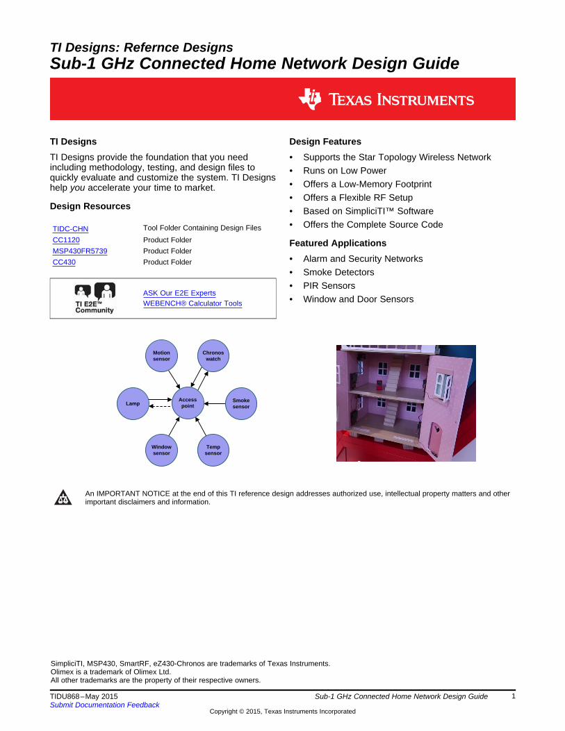
TI Designs: Refernce DesignsSub-1 GHz Connected Home Network Design Guide
TI Designs Design FeaturesTI Designs provide the foundation that you need • Supports the Star Topology Wireless Networkincluding methodology, testing, and design files to • Runs on Low Powerquickly evaluate and customize the system. TI Designs
• Offers a Low-Memory Footprinthelp you accelerate your time to market.• Offers a Flexible RF Setup
Design Resources • Based on SimpliciTI™ Software• Offers the Complete Source CodeTool Folder Containing Design FilesTIDC-CHN
CC1120 Product Folder Featured ApplicationsMSP430FR5739 Product Folder
• Alarm and Security NetworksCC430 Product Folder• Smoke Detectors• PIR Sensors
ASK Our E2E Experts• Window and Door SensorsWEBENCH® Calculator Tools
An IMPORTANT NOTICE at the end of this TI reference design addresses authorized use, intellectual property matters and otherimportant disclaimers and information.
SimpliciTI, MSP430, SmartRF, eZ430-Chronos are trademarks of Texas Instruments.Olimex is a trademark of Olimex Ltd.All other trademarks are the property of their respective owners.
1TIDU868–May 2015 Sub-1 GHz Connected Home Network Design GuideSubmit Documentation Feedback
Copyright © 2015, Texas Instruments Incorporated

Key System Specifications www.ti.com
1 Key System Specifications
Table 1. 1 Key System Specifications
PARAMETER SPECIFICATIONS COMMENTSSymbol Rate 50 kbps ConfigurableFrequency Band 868 MHz Configurable to other frequency bands.
See Section 4.9.Modulation GFSKNetwork topology Full-house coverage, star network based
on SimpliciTIFlash and RAM requirements 10kB Flash, 0.5kB RAMBattery life Up to 20 years Based on measurements in Section 8.
2 Sub-1 GHz Connected Home Network Design Guide TIDU868–May 2015Submit Documentation Feedback
Copyright © 2015, Texas Instruments Incorporated
www.ti.com System Description
2 System DescriptionThe TI Design for the connected home network shows how to create a Sub-1 GHz star network with full-house coverage for security and sensor applications (see Achieving Optimum Radio Range (SWRA479).This TI Design is a pure software design using standard TI development boards from TI’s Sub-1 GHzwireless connectivity portfolio. To learn more about TI’s 169 MHz, 315 MHz, 433 MHz, 470 MHz, 868MHz, 915 MHz, and 920 MHz solutions, see our Sub-1 GHz page. In this network, the central device istypically powered directly while the other devices are battery powered.
2.1 CC1120 DeviceThe CC1120 device is a fully integrated single-chip radio transceiver designed for high performance atvery low-power and low-voltage operation. All filters are integrated, rendering expensive external SAWand IF filters unnecessary. The device is intended for the industrial, scientific, and medical (ISM) usageand short-range device (SRD) frequency bands at 164 to 192 MHz, 274 to 320 MHz, 410 to 480 MHz, and820 to 960 MHz.
The CC1120 device provides extensive hardware support for packet handling, data buffering, bursttransmissions, clear channel assessment, link quality indication, and Wake-On-Radio. The CC1120 deviceis controlled through an SPI interface. The CC1120 device is typically used with a microcontroller and afew external passive components.
2.2 MSP430FR5739 Microcontroller ConfigurationThe MSP430F543xA and MSP430F541xA series are microcontroller configurations with the following:• Three 16-bit timers• A high-performance 12-bit analog-to-digital converter (ADC)• Up to four universal serial communication interfaces (USCIs)• A hardware multiplier• DMA• A real-time clock module with alarm capabilities• Up to 87 I/O pins
2.3 CC430F6137 Microcontroller ConfigurationThe CC430F61xx series are microcontroller SoC configurations that combine the excellent performance ofthe CC1101 sub-1-GHz RF transceiver with the following:• The MSP430™ CPUXV2• Up to 32 KB of in-system programmable flash memory• Up to 4 KB of RAM• Two 16-bit timers• A high-performance 12-bit analog-to-digital converter (ADC) with eight external inputs plus internal
temperature and battery sensors on CC430F613x devices• A comparator• Universal serial communication interfaces (USCIs)• A 128-bit AES security accelerator• A hardware multiplier• DMA• A real-time clock (RTC) module with alarm capabilities• An LCD driver• Up to 44 I/O pins
For more information on each of these devices, see the product folders at www.TI.com.
3TIDU868–May 2015 Sub-1 GHz Connected Home Network Design GuideSubmit Documentation Feedback
Copyright © 2015, Texas Instruments Incorporated
Out:Status
Sensor data
Out:Status
In:Commands (broadcast)
Out:StatusSensor data
Out:Status
Sensor data
Out:StatusSensor dataData requests
In:System status
Chronos watchED
Smoke sensor ED
Access point
Motion sensor ED
LampED
Window sensorED
Out:StatusSensor data
Temp sensor ED
Block Diagram www.ti.com
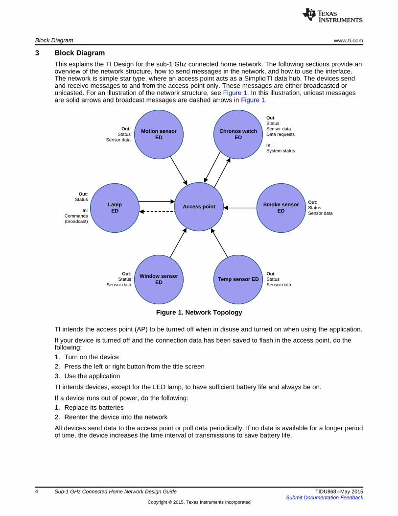
3 Block DiagramThis explains the TI Design for the sub-1 Ghz connected home network. The following sections provide anoverview of the network structure, how to send messages in the network, and how to use the interface.The network is simple star type, where an access point acts as a SimpliciTI data hub. The devices sendand receive messages to and from the access point only. These messages are either broadcasted orunicasted. For an illustration of the network structure, see Figure 1. In this illustration, unicast messagesare solid arrows and broadcast messages are dashed arrows in Figure 1.
Figure 1. Network Topology
TI intends the access point (AP) to be turned off when in disuse and turned on when using the application.
If your device is turned off and the connection data has been saved to flash in the access point, do thefollowing:1. Turn on the device2. Press the left or right button from the title screen3. Use the application
TI intends devices, except for the LED lamp, to have sufficient battery life and always be on.
If a device runs out of power, do the following:1. Replace its batteries2. Reenter the device into the network
All devices send data to the access point or poll data periodically. If no data is available for a longer periodof time, the device increases the time interval of transmissions to save battery life.
4 Sub-1 GHz Connected Home Network Design Guide TIDU868–May 2015Submit Documentation Feedback
Copyright © 2015, Texas Instruments Incorporated

www.ti.com System Design Theory
4 System Design Theory
4.1 Message Format and TypesThe system has two message formats: unicast messages and broadcast messages.
4.1.1 Unicast MessagesUnicast messages are sent either from devices to access point or from access point to devices. Thepayload of the unicast messages is a four byte frame sent as unsinged integers. For an example of theunicast message frame, see Figure 2.
Device Type Message Type Message Packet Number
Figure 2. Unicast Message Frame
The frame is split into three types:• Device type• Message type• Predefined message (or a sensor value)
Sensor values are detected and parsed depending on device and data type.
The device type indicates what kind of device sent the message. Types of devices include the following:• Access Point• Motion Sensor• Alarm Motion Sensor• Temperature Sensor• Door Sensor• LED Lamp• Chronos Watch
Message types indicate what kind of message is sent. Message types include the following:• Event• Data• Command• Status
The predefined messages include the following:• Motion/No Motion• Open/Closed• Smoke/No Smoke• Arm/Disarm Alarm• Alarm Toggle• Data Request• Status OK
5TIDU868–May 2015 Sub-1 GHz Connected Home Network Design GuideSubmit Documentation Feedback
Copyright © 2015, Texas Instruments Incorporated
System Design Theory www.ti.com
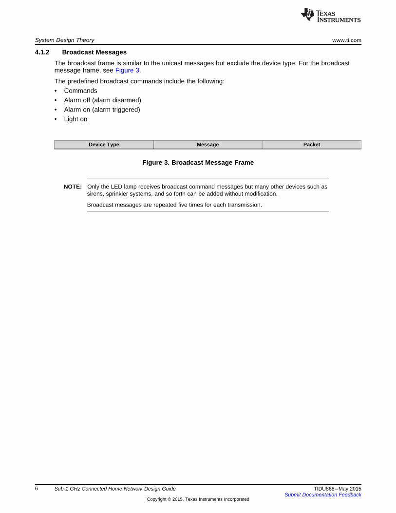
4.1.2 Broadcast MessagesThe broadcast frame is similar to the unicast messages but exclude the device type. For the broadcastmessage frame, see Figure 3.
The predefined broadcast commands include the following:• Commands• Alarm off (alarm disarmed)• Alarm on (alarm triggered)• Light on
Device Type Message Packet
Figure 3. Broadcast Message Frame
NOTE: Only the LED lamp receives broadcast command messages but many other devices such assirens, sprinkler systems, and so forth can be added without modification.
Broadcast messages are repeated five times for each transmission.
6 Sub-1 GHz Connected Home Network Design Guide TIDU868–May 2015Submit Documentation Feedback
Copyright © 2015, Texas Instruments Incorporated

Erase flash Left or right?Listen for button
press
Info to flash Right?
Button pressed
Toggle alarm
Alarm armed?
IDLE
Receive unicast event message
from ED
Process message
Timer interrupt(3 minutes)
Check for inactive peers
Join request(ED)
Enter ED into PAN
Left
RightLeft
Right
www.ti.com System Design Theory
4.2 Device Description
4.2.1 Access Point (AP)The access point is a SimpliciTI data hub and contains most of the logic of the network. When on, theaccess point loads previously-saved linked devices from flash. The access point listens continuouslyreceives devices trying to connect to the network and messages from connected devices. The accesspoint receives messages from devices and acts according to state of alarm and content of the message.To use access point in demo applications, ensure that you save your link data to flash. For a flowchartillustrating the processes of the access point, see Figure 4.
Message processing has been split up into one flowchart for each type of message.The process that checks for inactive peers checks if a device sent status messages in the last two minutes. If not,access point sets device status on LCD to inactive.
Figure 4. Access Point Flowchart
.
7TIDU868–May 2015 Sub-1 GHz Connected Home Network Design GuideSubmit Documentation Feedback
Copyright © 2015, Texas Instruments Incorporated
Process message Arm alarm?
Toggle alarm?
Disarm alarm?
Data request?
Arm alarm
Alarm armed?
Disarm alarm
Send unicast message response
to ED(system status)
Broadcast alarm OFF
IDLEYes
Yes
Yes
Yes
No
No
NoNo
Yes
Process messageMotion
detected?Alarm armed? Broadcast light ON
IDLE
Set alarm to triggered(active)
Smoke detected?
Door break? Alarm armed?
Yes
Yes No
No
Yes
No
Yes No
System Design Theory www.ti.com
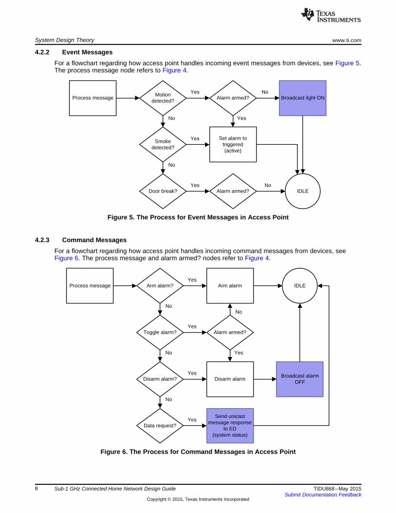
4.2.2 Event MessagesFor a flowchart regarding how access point handles incoming event messages from devices, see Figure 5.The process message node refers to Figure 4.
Figure 5. The Process for Event Messages in Access Point
4.2.3 Command MessagesFor a flowchart regarding how access point handles incoming command messages from devices, seeFigure 6. The process message and alarm armed? nodes refer to Figure 4.
Figure 6. The Process for Command Messages in Access Point
8 Sub-1 GHz Connected Home Network Design Guide TIDU868–May 2015Submit Documentation Feedback
Copyright © 2015, Texas Instruments Incorporated

Process message Update ED data IDLE
Process messageClear device timeout-timer
IDLE
www.ti.com System Design Theory
4.2.4 Status MessagesStatus messages indicate to access point if a device is active or inactive. All devices send statusmessages every two minutes. If the access point has not received a status message for a timeout period,the access point considers the device inactive and denotes the inactivity in the GUI. Each device linked tothe access point has an activity timer. If the timer counts two minutes, the device becomes inactive. Eachtime the access point receives a status message, it clears the timer for that device. For a flowchartregarding how access point handles the incoming status messages from devices, see Figure 7.
Figure 7. The Process for Status Messages in Access Point
4.2.5 Data MessagesData messages contain only temperature data and print to the LCD instead of being buffered or saved. TIintends data messages to be parsed. This process depends on the type of device and type of datareceived. For a flowchart regarding how the access point handles incoming data messages from devices(for example, the temperature sensor), see Figure 8.
Figure 8. The Data Message Process in Access Point
9TIDU868–May 2015 Sub-1 GHz Connected Home Network Design GuideSubmit Documentation Feedback
Copyright © 2015, Texas Instruments Incorporated

Timer interrupt(1 minute)
Sleep
Button pressed
Send temperature data unicast to AP
Send temperature data unicast to AP
Send status unicast to AP
System Design Theory www.ti.com
4.3 Temperature SensorThe temperature sensor operates in sleep mode after starting up (in both the radio and CPU) and wakesperiodically to send status and temperature data unicasts to the access point. If using the TrxEBevaluation board, press the left button to cause a port interrupt to wake up the temperature sensor.
The device uses the built-in temperature sensor in the radio (CC112x or CC12xx) that requires one-pointcalibration. Set the calibration value defined in c112x temp read.c. The temperature value is accurate onlyin proximity to the temperature used for calibration. The sensor sends data as an unsigned integercausing only positive Celsius temperatures to give a correct value on the system GUI. For an illustration ofoperating of the temperature sensor, see Figure 9.
Figure 9. Temperature Sensor Operation
10 Sub-1 GHz Connected Home Network Design Guide TIDU868–May 2015Submit Documentation Feedback
Copyright © 2015, Texas Instruments Incorporated
Timer interrupt(1 minute)
Sleep
Button pressed
Send temperature data unicast to AP
Send temperature data unicast to AP
Send status unicast to AP
www.ti.com System Design Theory
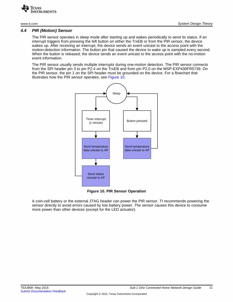
4.4 PIR (Motion) SensorThe PIR sensor operates in sleep mode after starting up and wakes periodically to send its status. If aninterrupt triggers from pressing the left button on either the TrxEB or from the PIR sensor, the devicewakes up. After receiving an interrupt, the device sends an event unicast to the access point with themotion-detection information. The button pin that caused the device to wake up is sampled every second.When the button is released, the device sends an event unicast to the access point with the no-motionevent information.
The PIR sensor usually sends multiple interrupts during one-motion detection. The PIR sensor connectsfrom the SPI header pin 3 to pin P2.4 on the TrxEB and from pin P2.0 on the MSP-EXP430FR5739. Onthe PIR sensor, the pin 1 on the SPI header must be grounded on the device. For a flowchart thatillustrates how the PIR sensor operates, see Figure 10.
Figure 10. PIR Sensor Operation
A coin-cell battery or the external JTAG header can power the PIR sensor. TI recommends powering thesensor directly to avoid errors caused by low battery power. The sensor causes this device to consumemore power than other devices (except for the LED actuator).
11TIDU868–May 2015 Sub-1 GHz Connected Home Network Design GuideSubmit Documentation Feedback
Copyright © 2015, Texas Instruments Incorporated

Timer interrupt(2 minutes)
Sleep
Smoke detected
6HQG�³VPRNH�
GHWHFWHG´�XQLFDVW�
to AP
Send status unicast to AP
Still smoke?6HQG�³QR�VPRNH�
GHWHFWHG´�XQLFDVW�
to AP
Yes
No
System Design Theory www.ti.com
4.5 Smoke SensorThe smoke sensor operates in sleep mode after starting up and wakes every minute and sends a statusunicast to the access point. If you press the left button, an interrupt wakes the device. This interrupt sendsa event unicast indicating that smoke is detected to the access point. When the device registers asreleased, the button pin is sampled each second. The device registers the sample when smoke is nolonger detected and a sends a unicast event message of no smoke indicated to the access point. For anillustration of how the smoke sensor operates, see Figure 11.
Figure 11. Smoke Sensor Operation
12 Sub-1 GHz Connected Home Network Design Guide TIDU868–May 2015Submit Documentation Feedback
Copyright © 2015, Texas Instruments Incorporated

Timer interrupt(2 minutes)
Sleep
Intrusion detected(left button pressed)
6HQG�³RSHQ´�
unicast to APSend status
unicast to AP
Still open?6HQG�³FORVHG´�
unicast to AP
Yes
No
Toggle alarm(right button
pressed
6HQG�³WRJJOH�
DODUP´�XQLFDVW�WR�
AP
www.ti.com System Design Theory
4.6 Door and Window SensorThe door and window sensor is similar to the smoke sensor. The door emulates door breakage with theleft button like the smoke sensor emulates smoke detection. The door and window sensor can send thealarm toggle command unicast to the access point by pressing the right button. For an example of how thedoor and window sensor operates, see Figure 12.
Figure 12. Door and Window Sensor Operation
13TIDU868–May 2015 Sub-1 GHz Connected Home Network Design GuideSubmit Documentation Feedback
Copyright © 2015, Texas Instruments Incorporated

Timer interrupt(1 minute)
Idle
RX
Receive broadcast message
Send status unicast to AP
What command?
Start LED blinking(alarm)
Turn off main LED
Alarm off
Alarm on
Turn on LED for 5 seconds(on timer)
Light on Optional RGB LEDs blink red
Optional RGB LEDs turn green for a short while,
then turn off
System Design Theory www.ti.com
4.7 LED Lamp ActuatorAfter starting up the LED lamp actuator, the MCU is always on and the radio is always in RX. If the LEDlamp actuator detects a message, it checks if the message was broadcasted. If the message wasbroadcasted, it reads the message and follows the process in the flowchart in Figure 13. The LED lampactuator sends status unicasts to the access point every minute.
You can connect an additional RGB, LED, or LED strip. When you connect a strip, P10.1 is red, P10.3 isgreen, and P10.5 is blue. Red and green are available. The LED lamp actuator can receive three differentcommands: alarm off, alarm on, and light on. Alarm on indicates that an alarm has been triggered. Whenthe alarm has been triggered, the LED lamp actuator will start flashing its light and RGB LED light ifconnected. If the command is alarm off, actuator disarms the alarm and stops flashing its light. If the RGBLED light is connected, it will turn green for a few seconds before turning off. The light on command willturn the light on for five seconds. You must use the buttons on the actuator to continue from the titlescreen.
Figure 13. LED Lamp Actuator Operation
If the device is turned off, it will reenter the network after starting up (continue from title screen) if anaccess point is present. The LED lamp actuator consumes more power than other devices and TIrecommends powering it directly.
14 Sub-1 GHz Connected Home Network Design Guide TIDU868–May 2015Submit Documentation Feedback
Copyright © 2015, Texas Instruments Incorporated

Sleep
Button pressed
Which button?Door intrusion
detectedSmoke detected
Motion detected
Button held for >3 seconds?
Button held for >3 seconds?
Arm alarm
Re-link Set time*
Disarm alarm
Down
Backlight button
No
#*No
Yes Yes
Up
www.ti.com System Design Theory
4.8 Chronos WatchAfter starting up, the Chronos watch operates in sleep mode. Interrupts wake the watch each second toincrease the clock counter. The Chronos watch polls data from the access point every two seconds to getthe alarm status.
By using the three button on the right, the Chronos watch can emulate the three alarm types, the arm, anddisarm commands. The watch tries to relink five times. If unsuccessful, the device will no longer link to anyaccess point or device. To reenter the network, reenter relink mode. After a successful relink, the watchwill display a heart.
If the watch is unable to poll data for five consecutive polls, the device increases the poll interval to oneminute to save battery life and clears the bottom line on the display. If the watch is unable to poll data, thedevice might be out of the range of the access point or the access point might be off. When in range of anactive access point, the watch will poll data, update its display, and change the polling interval to each twoseconds.
An example of the process of button events for the Chronos watch, see Figure 14. For an example of theprocess of timer events in the Chronos watch, see Figure 15.
Figure 14. The Process of Button Events in the Chronos Watch
15TIDU868–May 2015 Sub-1 GHz Connected Home Network Design GuideSubmit Documentation Feedback
Copyright © 2015, Texas Instruments Incorporated

Sleep
Timer interrupt(1 minute)
Timer interrupt(poll rate)
Send status unicast to AP
Send data request unicast to AP
Received answer from
AP?
Missed polls >5?
Set long poll rateReceive alarm
status unicast from AP
Set short poll rateUpdate Chronos
display
Timer interrupt(1 second)
Tick clock
Yes
No
Yes
No
System Design Theory www.ti.com
Figure 15. Process of Timer Events in the Chronos Watch
NOTE: A variant of the Chronos project in the TI Design software exists that TI intends to be usedas a monitor instead of a watch.
That device shows a static message on the top row of the display instead of the time.
16 Sub-1 GHz Connected Home Network Design Guide TIDU868–May 2015Submit Documentation Feedback
Copyright © 2015, Texas Instruments Incorporated

www.ti.com System Design Theory
4.9 Physical Layer ConfigurationThis TI Design uses the physical layer and radio configuration. For the information regarding the settingsof the physical layer and radio configurations, see Table 2. These settings are the same as those in theEasyMode software in TI LPRF EASYMODE (SWRA472).
Table 2. Physical Layer and Radio Configuration
Modulation format 2-GFSKDeviation 25 kHzBit rate 50 kbit/s
RX filter bandwidth 100 kHzCenter frequency 868 MHzTX output power 15 dBm
Sync Word 0x55557A0E
The physical layer and radio configuration can be changed by using SmartRF™ Studio 7 to complete thefollowing steps:1. Start SmartRF Studio 7.2. Choose CC1120.3. Select either the Packet TX or Packet RX tab.4. Set the physical parameters.5. Press Register Export.6. Under Templates, select SimpliciTI Settings.7. Under Template View/Edit, check the Parameter summary.8. Under registers, press Select.9. Press >>> to add all registers to the export.10. Press Ok.11. Press Export to file.12. Navigate to the project root .13. Navigate to Components\mrfi\smartrf\CC1120.14. To save the old configuration, rename the smartrf_CC1120.h file (TI recommended).15. Save the exported file as smartrf_CC1120.h.16. Recompile all nodes in the network.
The new configuration should affect all nodes.
17TIDU868–May 2015 Sub-1 GHz Connected Home Network Design GuideSubmit Documentation Feedback
Copyright © 2015, Texas Instruments Incorporated

Getting Started www.ti.com
5 Getting Started
5.1 HardwareTo evaluate this TI Design, you need at least one Performance Line Development Kit (CC1120DK). Thiskit contains everything to make an access point and one device based on both the TrxEB and CC1120evaluation module.
The software provided as a part of this TI Design also supports the EXP430FR5739 LaunchPad for alldevices except the LED lamp. This device has a few LEDs, instead of an LCD, and offers less visualfeedback.
The PIR sensor used in the motion sensor design is based on Ultra-Low Power Motion Detection Usingthe MSP430F2013 (SLAA283A). The hardware used in this TI Design is available from Olimex™.
The hardware to run the complete TI Design with eight devices and one access point follows:• 1 × CC1120DK• 6 × MSP-EXP430FR5739• 3 × CC1120EMK (868-915 MHz)• 1 × eZ430-Chronos™• 2 × MSP430-PIR
CC1120DK – Performance Line Development Kithttp://www.ti.com/tool/cc1120dk
The CC1120DK consists of the following:• Two TrxEB evaluation boards• Two CC1120 evaluation modules for 868 MHz with antennas• A MSP430 Debug Probe• All cables
MSP-EXP430FR5739 Experimenter Boardhttp://www.ti.com/tool/msp-exp430fr5739
The experimenter board consists of the following:• The experimenter board• A native connector for adding a CC1120 evaluation module• A CC1120EMK
CC1120EMK – Evaluation Module Kit 868-915 MHzhttp://www.ti.com/tool/CC1120EMK-868-915
CC1120 evaluation module kit consists of the following:• Two CC1120 evaluation modules and antennas• An evaluation or experimenter board
eZ430 Chronos Wireless Development Toolhttp://www.ti.com/tool/ez430-chronos
The Chronos development kit is a self-contained development kit that contains everything to get startedwith the CC430 platform. The Chronos watch can be used to view the status of the system, send testmessages, and disarm the alarm.
MSP430-PIR Motion Sensor
https://www.olimex.com/Products/MSP430/Starter/MSP430-PIR/
The MSP430-PIR device is based on Ultra-Low Power Motion Detection Using the MSP430F2013(SLAA283). The TI Design software packet includes software to program this device.
18 Sub-1 GHz Connected Home Network Design Guide TIDU868–May 2015Submit Documentation Feedback
Copyright © 2015, Texas Instruments Incorporated

www.ti.com Firmware
6 FirmwareThe MSP430 device supports the IAR Embedded Workbench. The software in this TI Design has beentested with a IAR Embedded Workbench for the MSP430 version 6.10.5.
Get a 30-day trial version from IAR at: http://www.iar.com/Service-Center/Downloads/
6.1 Installing the Firmware: Setting up the IARTo get started with this TI Design using IAR Embedded Workbench, you need a TrxEB device, aCC1120EM device for the access point, and hardware for one device. The device can either be anotherTrxEB device and a CC1120EM device, a EXP430FR5739 device and a CC1120EM device, or a eZ430-Chronos device.
To program a board, do the following:1. Open the IAR Embedded Workbench for the MSP430 device.2. Go to File.3. Go to Open.4. Go to Workspace.5. Find the directory with the TI Design software package.6. Go to Projects\Examples\TrxEB\Connected_Home\IAR7. Open Connected_Home.eww8. In Figure 16, select device compile.
Selecting the device will include only the source files and configuration file for that device.
Figure 16. Connected Home IAR Project Workspace
9. Go to Project.10. Press F7 to Make.11. Connect the board.12. Go to Project.13. Press Shift-D to download and debug.
The software for the MSP430-PIR device can be found in Projects\Examples\Applications\TI_Design_Sensor_Application\PIR-sensor. Program this device using the steps in this section.
19TIDU868–May 2015 Sub-1 GHz Connected Home Network Design GuideSubmit Documentation Feedback
Copyright © 2015, Texas Instruments Incorporated

Firmware www.ti.com
6.2 Running the Firmware: Quick StartTo start the firmware, do the following:1. Ensure all devices are off.2. Turn on the access point.3. Press the left or right button to continue from title screen on the access point.4. Start the devices one at a time (On TrxEB devices, press the left or right button to continue from the
start screen. On the Chronos, press up. On EXP430FR5739, press nothing).
If some devices are labeled as inactive or do not appear on the access point display, restart the deviceand check the batteries.
Using the Access Point Interface• Press the right button to toggle the arm or disarm status of the alarm.
1. Press the left button to enter the menu for to erase or save data to flash.2. Press left button again to erase data on the flash.3. Press the right button to save the device information to the flash.
• Save the information of the device to flash to avoid having to restart all devices to relink to accesspoint the next time you use the system.
Using the PIR Sensor Interface• Move in front of the PIR sensor to turn on the light or trigger the alarm (depending on alarm and
project setting).• Press and hold the left button to emulate the motion detection from the PIR sensor (if no PIR sensor is
present or if the batteries of the sensor are dead).
Using the Door and Window Sensor Interface• Press and hold the left button to emulate the door or window being open or closed (while button is
pressed, the device considers the door or window open).• Press the right button to toggle the arm or disarm status of the alarm.
Using the Smoke Sensor Interface• Press and hold the right button to indicate that smoke is detected (while the button is pressed, the
device considers smoke detected).
Using the Chronos Watch Interface• Press * to arm the alarm.• Press # to disarm and deactivate the alarm.• Press and hold up to emulate detecting a door intrusion.• Press and hold the backlight button to emulate detecting a motion (middle right button).
20 Sub-1 GHz Connected Home Network Design Guide TIDU868–May 2015Submit Documentation Feedback
Copyright © 2015, Texas Instruments Incorporated

www.ti.com Firmware
6.3 Quick Event Reference
6.3.1 Emulating a Broken Door or WindowOn the door and window sensor and the access point, the display will show door open or window openwhile the button is pressed. When the button is released, the display will show door closed or windowclosed. If the alarm is armed, the LED lamp actuator will blink until the alarm is disarmed.
6.3.2 Emulating Smoke DetectionOn the smoke sensor and the access point, the display will show smoke while button is pressed and nosmoke when the button is released. The alarm will trigger and the LED lamp actuator will blink until thealarm is disarmed.
6.3.3 Toggling the Alarm StatusYou can toggle the alarm status from armed to disarmed on the door sensor, the Chronos watch, and theaccess point. If the alarm is triggered, toggling the alarm status will deactivate the alarm.
6.3.4 Arming and Disarming the PIR SensorOn the PIR sensor and the access point, the display will show motion when the device detects it, and nomotion when the device detects nothing. The device checks for motion every second. If the alarm isarmed, the LED lamp actuator will blink until the alarm is disarmed. If the alarm is not armed, the LEDlamp actuator will turn the light on for 5 seconds on a timer. To turn the light off sooner, send a commandto disarm the alarm from the access point, the Chronos watch, or the door sensor.
6.3.5 Setting Periodic EventsEvery two minutes, all devices send a status message to the access point. If the access point does notreceive a status message from a device after three minutes, the access point sets the device status asinactive on the LCD. The temperature sensor sends the temperature value to the access point everyminute. The access point and temperature sensor LCD display this value.
6.3.6 Using the Chronos Watch to Emulate EventsTo emulate the door, motion sensor, and smoke alarm, do the following:1. Press and hold up to emulate the door opening and closing.2. Press and hold ¤ to emulate the motion sensor.3. Press and hold down to emulate the smoke alarm.
To set the time, do the following:1. Press and hold * to relink the watch to the access point.2. Press and hold # to set the hour.3. Toggle up and down to set the hour.4. Press # to set the minutes.5. Toggle up and down buttons to set the minutes.6. Press # to exit.
6.3.7 LED Lamp ActuatorThe actuator receives messages from the access point to turn on light or activate the alarm. This deviceconsumes power at a higher rate than the other devices and should be powered directly.
21TIDU868–May 2015 Sub-1 GHz Connected Home Network Design GuideSubmit Documentation Feedback
Copyright © 2015, Texas Instruments Incorporated

PC
MSP430FR5739
Agilent N6705B DC power
Test Setup www.ti.com
7 Test SetupWe used a USB cable to connect a Agilent N6705B DC Power Analyzer to a PC to record themeasurements. A USB connection to the PC powered the MSP430FR5739 device.
We used the setup in Figure 17 when measuring the radio. When we measured the MSP430 device, weused the MSP_PWR jumper instead of the RF_PWR jumper.
Figure 17. Radio Measurement Setup
8 Test DataMost nodes in the connected home network are battery-powered but must last a long time. Because theconnected home network has an asymmetric power budget, the battery nodes can operate at low powerand assume the access point is always on. The nodes can send a message at anytime and assume thatthe access point will receive it.
For an illustration of the active power consumption of the CC1120 transceiver of a door and windowsensor during the transmission of a device status, see Figure 18 .Figure 18 illustrates the stages wherethe device wakes up, enters TX, changes mode to RX, waits in RX for an ACK, and then goes to sleep.Sending a status and getting an acknowledge takes about 11.1 ms. The average power consumptionduring this period is approximately 28.5 mA.
For the average current of the CC1120 device when the radio is in sleep mode, see Figure 19.
22 Sub-1 GHz Connected Home Network Design Guide TIDU868–May 2015Submit Documentation Feedback
Copyright © 2015, Texas Instruments Incorporated

www.ti.com Test Data
Figure 18. Door and Window Sensor Average Power Consumption While Active, CC1120 Radio Only
Figure 19. Window and Door Sensor Power Consumption During Sleep Mode, CC1120 Radio Only
23TIDU868–May 2015 Sub-1 GHz Connected Home Network Design GuideSubmit Documentation Feedback
Copyright © 2015, Texas Instruments Incorporated

Design Files www.ti.com
The nodes send a status message every two minutes by default. For a calculation of the average powerconsumption, see Table 3. This average power consumption is based on real power measurements on theCC1120 device and the MSP430FR5739 device, where sleep means power mode 3 (PM3). To have allpins of the MSP430FR5739 device in a configuration that draw the least power, we took specialconsiderations. The exact pin configuration will depend on the board and what pins are used.
The calculations in Table 3 assume the added asynchronous radio activity created when sensor valuesare triggered to be sent will be less than the contribution of the status messages over time.
With the average current in Table 3 and two AA batteries connected with 2100 mAh capacity, the averagebattery time of the node is approximately 20 years.
NOTE: The MSP in Table 3 has 9 µA sleep current which consumes the majority of power budget.
With a sleep current of approximately 1 µA, the MSP430FR4133 device has a higher batterylife.
Table 3. Average Power Consumption
Time [ms] CC1120 [mA] MSP430 Time × CurrentActive 11.10 28.5 0.8 325.23Sleep 119988.9 0.00015 0.009 1097.9
Average Current [µA] 11.9
Example End Device Life Time (1)
9 Design FilesHardware reference designs in this software reference design are available for the different platforms inthe following reference designs:
CC1120EM 868/915MHz reference design
CC430 Chronos reference design
9.1 Bill of MaterialsTo download the bill of materials, see the following reference designs:
CC1120EM 868/915MHz reference design
CC430 Chronos reference design
9.2 Software FilesTo download the software files, see the design files at TIDC-CHN.
10 References
1. TI LPRF Easy Mode Application Note (SWRA472)2. Achieving Optimum Radio Range (SWRA479)
24 Sub-1 GHz Connected Home Network Design Guide TIDU868–May 2015Submit Documentation Feedback
Copyright © 2015, Texas Instruments Incorporated

www.ti.com About the Author
11 About the AuthorNIKLAS NORIN is an applications engineer at TI, where he works with software and firmware for thewireless connectivity team. Niklas holds an M.Sc in Electronics Engineering.
TORSTEIN ERMESJØ is an applications engineer at TI, where he works with hardware setup and systemdesign for the wireless connectivity team. Torstein holds an M.Sc in Electronics Engineering.
25TIDU868–May 2015 Sub-1 GHz Connected Home Network Design GuideSubmit Documentation Feedback
Copyright © 2015, Texas Instruments Incorporated

IMPORTANT NOTICE FOR TI REFERENCE DESIGNS
Texas Instruments Incorporated ("TI") reference designs are solely intended to assist designers (“Buyers”) who are developing systems thatincorporate TI semiconductor products (also referred to herein as “components”). Buyer understands and agrees that Buyer remainsresponsible for using its independent analysis, evaluation and judgment in designing Buyer’s systems and products.TI reference designs have been created using standard laboratory conditions and engineering practices. TI has not conducted anytesting other than that specifically described in the published documentation for a particular reference design. TI may makecorrections, enhancements, improvements and other changes to its reference designs.Buyers are authorized to use TI reference designs with the TI component(s) identified in each particular reference design and to modify thereference design in the development of their end products. HOWEVER, NO OTHER LICENSE, EXPRESS OR IMPLIED, BY ESTOPPELOR OTHERWISE TO ANY OTHER TI INTELLECTUAL PROPERTY RIGHT, AND NO LICENSE TO ANY THIRD PARTY TECHNOLOGYOR INTELLECTUAL PROPERTY RIGHT, IS GRANTED HEREIN, including but not limited to any patent right, copyright, mask work right,or other intellectual property right relating to any combination, machine, or process in which TI components or services are used.Information published by TI regarding third-party products or services does not constitute a license to use such products or services, or awarranty or endorsement thereof. Use of such information may require a license from a third party under the patents or other intellectualproperty of the third party, or a license from TI under the patents or other intellectual property of TI.TI REFERENCE DESIGNS ARE PROVIDED "AS IS". TI MAKES NO WARRANTIES OR REPRESENTATIONS WITH REGARD TO THEREFERENCE DESIGNS OR USE OF THE REFERENCE DESIGNS, EXPRESS, IMPLIED OR STATUTORY, INCLUDING ACCURACY ORCOMPLETENESS. TI DISCLAIMS ANY WARRANTY OF TITLE AND ANY IMPLIED WARRANTIES OF MERCHANTABILITY, FITNESSFOR A PARTICULAR PURPOSE, QUIET ENJOYMENT, QUIET POSSESSION, AND NON-INFRINGEMENT OF ANY THIRD PARTYINTELLECTUAL PROPERTY RIGHTS WITH REGARD TO TI REFERENCE DESIGNS OR USE THEREOF. TI SHALL NOT BE LIABLEFOR AND SHALL NOT DEFEND OR INDEMNIFY BUYERS AGAINST ANY THIRD PARTY INFRINGEMENT CLAIM THAT RELATES TOOR IS BASED ON A COMBINATION OF COMPONENTS PROVIDED IN A TI REFERENCE DESIGN. IN NO EVENT SHALL TI BELIABLE FOR ANY ACTUAL, SPECIAL, INCIDENTAL, CONSEQUENTIAL OR INDIRECT DAMAGES, HOWEVER CAUSED, ON ANYTHEORY OF LIABILITY AND WHETHER OR NOT TI HAS BEEN ADVISED OF THE POSSIBILITY OF SUCH DAMAGES, ARISING INANY WAY OUT OF TI REFERENCE DESIGNS OR BUYER’S USE OF TI REFERENCE DESIGNS.TI reserves the right to make corrections, enhancements, improvements and other changes to its semiconductor products and services perJESD46, latest issue, and to discontinue any product or service per JESD48, latest issue. Buyers should obtain the latest relevantinformation before placing orders and should verify that such information is current and complete. All semiconductor products are soldsubject to TI’s terms and conditions of sale supplied at the time of order acknowledgment.TI warrants performance of its components to the specifications applicable at the time of sale, in accordance with the warranty in TI’s termsand conditions of sale of semiconductor products. Testing and other quality control techniques for TI components are used to the extent TIdeems necessary to support this warranty. Except where mandated by applicable law, testing of all parameters of each component is notnecessarily performed.TI assumes no liability for applications assistance or the design of Buyers’ products. Buyers are responsible for their products andapplications using TI components. To minimize the risks associated with Buyers’ products and applications, Buyers should provideadequate design and operating safeguards.Reproduction of significant portions of TI information in TI data books, data sheets or reference designs is permissible only if reproduction iswithout alteration and is accompanied by all associated warranties, conditions, limitations, and notices. TI is not responsible or liable forsuch altered documentation. Information of third parties may be subject to additional restrictions.Buyer acknowledges and agrees that it is solely responsible for compliance with all legal, regulatory and safety-related requirementsconcerning its products, and any use of TI components in its applications, notwithstanding any applications-related information or supportthat may be provided by TI. Buyer represents and agrees that it has all the necessary expertise to create and implement safeguards thatanticipate dangerous failures, monitor failures and their consequences, lessen the likelihood of dangerous failures and take appropriateremedial actions. Buyer will fully indemnify TI and its representatives against any damages arising out of the use of any TI components inBuyer’s safety-critical applications.In some cases, TI components may be promoted specifically to facilitate safety-related applications. With such components, TI’s goal is tohelp enable customers to design and create their own end-product solutions that meet applicable functional safety standards andrequirements. Nonetheless, such components are subject to these terms.No TI components are authorized for use in FDA Class III (or similar life-critical medical equipment) unless authorized officers of the partieshave executed an agreement specifically governing such use.Only those TI components that TI has specifically designated as military grade or “enhanced plastic” are designed and intended for use inmilitary/aerospace applications or environments. Buyer acknowledges and agrees that any military or aerospace use of TI components thathave not been so designated is solely at Buyer's risk, and Buyer is solely responsible for compliance with all legal and regulatoryrequirements in connection with such use.TI has specifically designated certain components as meeting ISO/TS16949 requirements, mainly for automotive use. In any case of use ofnon-designated products, TI will not be responsible for any failure to meet ISO/TS16949.IMPORTANT NOTICE
Mailing Address: Texas Instruments, Post Office Box 655303, Dallas, Texas 75265Copyright © 2015, Texas Instruments Incorporated