stx - fordham plasticsfordhamplastics.com/.../2016/08/vertical-machine-x-pump-stx.pdf ·...
TRANSCRIPT
STXSERIES
STX10STX20
CATALOG 1503
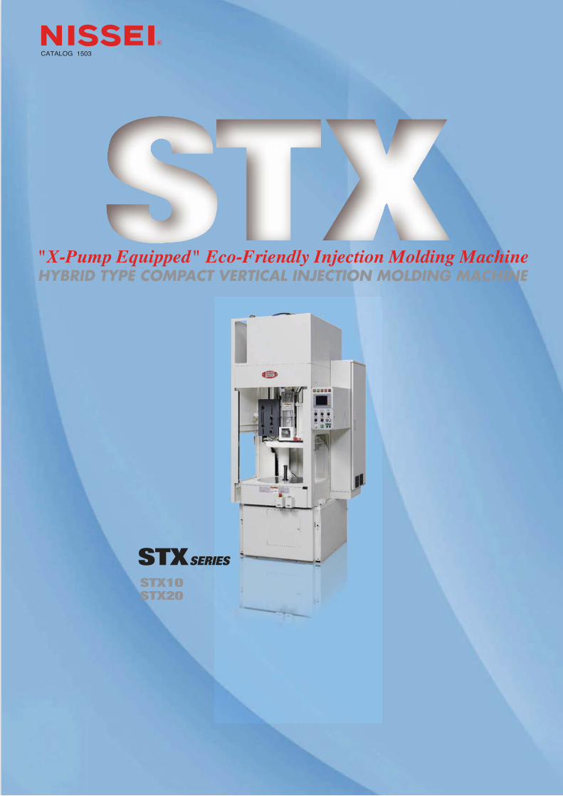
"X-Pump Equipped" Eco-Friendly Injection Molding Machine

STXSERIES
1
Eco-Friendly Injection Molding Machine (Hybrid Type)
Evolving from the ST Series, the STX Series is equipped with the hybrid "X-Pump" system, inheriting its compact design and automation flexibility from the predecessor.It offers outstanding injection performance and energy-efficiency, possessing excellent capability for the molding of high-precision automotive and electronics parts.
Flexible, Compact, and Energy-Efficient Vertical Machine!
Characteristics of The All-NEW STX Series
*In comparison with the conventional machines
●High-response injection Response time: approx. 1/2*●High-speed injection Injection speed: 1.3 times faster*●Stable control in ultra-low speed range
●Energy-saving Power consumption: approx. 40%*less●Space-saving design
●Tie-bar-less clamping mechanism ideal for insert molding

2
Best Technology Award (The Japan Society of Polymer Processing)
Energy-Conserving Machinery Award(The Japan Machinery Federation)
(Equipped with options)
(Equipped with options)
3
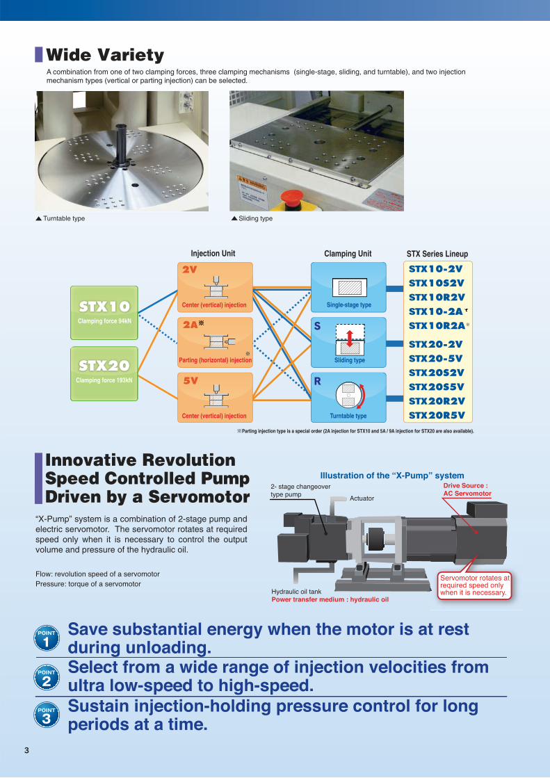
STX10-2VSTX10S2VSTX10R2VSTX10-2ASTX10R2A
STX20-2VSTX20-5VSTX20S2VSTX20S5VSTX20R2VSTX20R5V
S
R
Clamping force 94kN
Center (vertical) injection
Center (vertical) injection
Clamping force 193kN
Parting (horizontal) injection
Clamping UnitInjection Unit
Single-stage type
Sliding type
Turntable type
STX Series Lineup
※Parting injection type is a special order (2A injection for STX10 and 5A / 9A injection for STX20 are also available).
Wide VarietyA combination from one of two clamping forces, three clamping mechanisms (single-stage, sliding, and turntable), and two injection mechanism types (vertical or parting injection) can be selected.
Sliding typeTurntable type
Illustration of the “X-Pump” system
Actuator
Drive Source : AC Servomotor
Flow: revolution speed of a servomotorPressure: torque of a servomotor
2- stage changeover type pump
Hydraulic oil tankPower transfer medium : hydraulic oil
Servomotor rotates at required speed only when it is necessary.
Innovative Revolution Speed Controlled Pump Driven by a Servomotor
Save substantial energy when the motor is at rest during unloading.Select from a wide range of injection velocities from ultra low-speed to high-speed.Sustain injection-holding pressure control for long periods at a time.
“X-Pump” system is a combination of 2-stage pump and electric servomotor. The servomotor rotates at required speed only when it is necessary to control the output volume and pressure of the hydraulic oil.
4
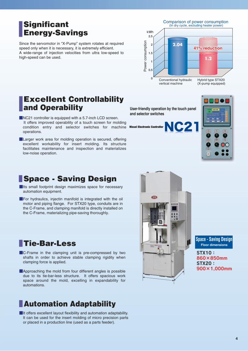
STX10:860×850mmSTX20:900×1,000mm
Floor dimensions
SignificantEnergy-Savings
Comparison of power consumption (In dry cycle, excluding heater power)
Pow
er c
onsu
mpt
ion
Conventional hydraulicvertical machine
Hybrid type STX20(X-pump equipped)
Excellent Controllability and Operability
■NC21 controller is equipped with a 5.7-inch LCD screen. It offers improved operability of a touch screen for molding
condition entry and selector switches for machine operations.
■Larger work area for molding operation is secured, offering excellent workability for insert molding. Its structure facilitates maintenance and inspection and materializes low-noise operation.
User-friendly operation by the touch panel and selector switches
Nissei Electronic Controller
Space - Saving Design
Space - Saving Design■Its small footprint design maximizes space for necessary
automation equipment.
■For hydraulics, injectin manifold is integrated with the oil motor and piping flange. For STX20 type, conduits are in the C-Frame, and clamping manifold is directly installed on the C-Frame, materializing pipe-saving thoroughly.
Since the servomotor in “X-Pump” system rotates at required speed only when it is necessary, it is extremely efficient.A wide-range of injection velocities from ultra low-speed to high-speed can be used.
Tie-Bar-Less■C-Frame in the clamping unit is pre-compressed by two
shafts in order to achieve stable clamping rigidity when clamping force is applied.
■Approaching the mold from four different angles is possible due to its tie-bar-less structure. It offers spacious work space around the mold, excelling in expandability for automations.
Automation Adaptability■It offers excellent layout flexibility and automation adaptability.
It can be used for the insert molding of micro precision parts or placed in a production line (used as a parts feeder).
41% reduction41% reduction

5
User-friendly operation by the touch panel and selector switches
Nissei Electronic Controller
■It is equipped with a compact, bright, and easy-to-see 5.7-inch color LCD screen.
■Velocity, pressure, time, and temperatures are entered via touch panel, and the operation panel is the selector switch type. It offers excellent operability and helps to prevent operation errors.
■High-speed multi CPU is equipped, offering excellent control response and operation stability.
■Injection process control is a 3-stage velocity and pressure type.
■It remotely controls nozzle and barrel temperatures, which are displayed and entered on the screen. Barrel heat-up function (calendar timer) comes standard.
■When errors occur (clamping, cycle, monitor, etc.), an alarm lamp will be activated, and the error message (error location and details) will be displayed. Timestamped error history is also displayed on the event screen, which can be utilized for production management and maintenance.
■15 molding conditions can be stored in the internal memory, which makes it easy to reload the conditions after mold change. 100 molding conditions can be stored if an external memory (optional USB flash drive) is used.
■A USB port comes standard. → External memory device (optional USB flash drive) can be
connected. It can save and read molding conditions as well as export screen shot and monitor data.
NC21 Main Screens
Injection
Production management
Temperature
Monitoring
Event
Condition change

6
STXSERIES
STX10-2V (Single-stage) STX10S2V (Sliding) STX10R2V (Turntable)
1.13×1.78×2.50 1.18×1.19×2.50 1.21×1.19×2.50
STX20-□V (Single-stage) STX20S□V (Sliding) STX20R□V (Turntable)
1.20×1.79×2.50 1.31×1.23×2.50 1.31×1.23×2.501.20×1.79×2.501.31×(φ22:2.59、φ26・30:2.64)×2.50
1.31×1.23×2.50
Performance Specifications
Models
Specification item
Injection Screw diameter
Injection capacity
Plasticizing capacity (PS)
Injection pressure
Injection rate
Injection velocity
Screw rotation speed
Hopper capacity (optional)
Clamping Clamping force
Clamping stroke
Min. mold thickness
Max. daylight opening
Tie bar clearance (H×V)
Ejector stroke
Others Pump motor
Heater band capacity
Hydraulic oil quantity
Machine dimensions (L×W×H)
Floor dimensions (L×W)
Machine weight
Unit
Injectiontype
●Actual plasticizing capacity may vary, depending on the materials and molding conditions.●Specifications are subject to change without notice due to continuous performance improvement.●1MPa = 10.2kgf/cm2 ≒10kgf/cm2 , 1kN = 0.102tf ≒ 0.1tf
mm
cm3
kg/h
MPa [kgf/cm2]
cm3/s
mm/s
rpm
L
kN [tf]
mm
mm
mm
mm
mm
kW
kW
L
m
m
t
Models
Specification item
Injection Screw diameter
Injection capacity
Plasticizing capacity (PS)
Injection pressure
Injection rate
Injection velocity
Screw rotation speed
Hopper capacity (optional)
Clamping Clamping force
Clamping stroke
Min. mold thickness
Max. daylight opening
Tie bar clearance (H×V)
Ejector stroke
Others Pump motor
Heater band capacity
Hydraulic oil quantity
Machine dimensions (L×W×H)
Floor dimensions (L×W)
Machine weight
Unit
Injectiontype
mm
cm3
kg/h
MPa [kgf/cm2]
cm3/s
mm/s
rpm
L
kN [tf]
mm
mm
mm
mm
mm
kW
kW
L
m
m
t

7
Main Equipment List
[Standard equipment]Injection unitClamping unit/mold
Injection unit
Molding system control/production control
Cooling/hydraulic oil
Operation safety
[Optional equipment]
Molding system control/production control
Cooling/hydraulic oil
Operation safety
Power
Clamping unit/mold
Maintenance, installation, and others
1 Mold LS rail with scale
2 Independent adjustment of clamping pressure
3 Low pressure clamping (velocity and pressure)
4 Initial mold opening velocity slowdown
5 Multiple ejector operation (1~9 times)
6 Ejector pause (0.00~9.99 seconds)
7 Ejector start timer
8 Ejector pressure/velocity setting
9 Mold set (mold mounting)
10 Clamping error alarm
1 Nozzle/barrel heater disconnection alarm
2 Nozzle temperature rise extension
3 2-point control of nozzle temperature
4 Barrel heater SSR
5 Hopper throat temperature control or hopper throat temperature display (on screen)
6 Back pressure control (manual setting with a digital handle or digital setting)
7 Decompression / before metering
8 Wear/corrosion resistant screw and barrel
9 Special-purpose screw and barrel
10 High-temperature specification barrel
11 Spring shut-off nozzle or hydraulic shut-off nozzle
12 Extended nozzle (length to be specified)/drooling prevention nozzle
13 Heat retaining nozzle
14 Barrel insulation cover
15 Hopper/hopper extension/hopper magnet
16 High injection speed specification: 300mm/s (2V and 5V)
1 Air blow
2 Hydraulic core pull or air core pull
3 Total running hour of molding machine
4 Stagnant material flow prevention
5 Take-out robot error alarm
6 Water alarm/air alarm
7 Switchable trilingual display (Japanese, English, and Chinese)
8 Emergency power shutdown delay timer
9 Hour meter (external installation)
1 Hydraulic oil temperature screen display (with upper/lower alarm)
2 Hydraulic oil heat-up
3 Oil temperature stabilizer
4 Cooling water filter
5 Additional cooling water circuit
6 Cooling circuit (with return stop valve)
7 Cooling circuit (with flow checker)
8 Water temperature gauge
9 Low oil level alarm
1 Alarm bell
2 Alarm lamp with a stand
3 Rotating beacon (Patlite) or layered indicator lamp (signal tower)
4 Emergency stop buttons (x2)
5 Door type side safety cover (with interlock)
6 Front safety light curtain (photoelectric safety device) (single - stage type)
7 Front safety door (sliding type / turntable type)
8 Primary power supply indicator lamp
9 High-pressure changeover confirmation lamp
1 Main power breaker or main power leakage breaker
2 Additional built-in electrical outlet
3 Outlet circuit power shutdown
1 Tool kit
2 Spare parts
3 SAT clamp
4 Easy clamp
5 Mold positioning pin and block
6 Mounting pad
7 Bed support base
8 Custom color paint (contact us to specify the area to be painted)
9 Ladder (footstool)
1 Digital setting of injection position
2 Injection process control: 3-speed and 3-pressure
3 Digital display of screw rotation speed
4 Back pressure control (manual setting)
5 Over-pack prevention circuit
6 Decompression
7 Injection start timer / Nozzle backward timer / Metering start timer
8 Automatic purging circuit (operation A)
9 Purging guard (with interlock, excluding single-stage type)
10 Screw cold-start prevention (all-point start-delay type)
11 Nozzle/barrel temperature PID control (screen setting)
12 Nozzle heater SSR
13 Nozzle/barrel temperature holding circuit (forced and emergency temperature holding)
14 Nozzle/barrel temperature upper limit alarm
15 Barrel insulation cover
1 Counter switch / Shot counter
2 Production control counter / Production lot control counter / Defective category counter
3 Grand total shot
4 Monitor display
5 Product pass/fail judgment function
6 Barrel heart -up / Automatic mold heat-up (calendar timer)
7 Internal memory for molding conditions (15 conditions)
8 USB port / Saving data to an external memory (USB flash drive)
9 Error history display (64 events)
10 Self-diagnostic function
11 Color LCD (5.7-inch)
12 Switchable bilingual display (Japanese and English)
13 Error display function
14 Emergency power shutdown
15 Cycle alarm
1 Cooling water manifold (3 circuits: hopper throat, upper mold, and lower mold)
2 Hydraulic oil temperature display
1 Alarm lamp/alarm buzzer
2 Emergency stop button (x1)
3 Safety light curtain (photoelectric safety device) (sliding type / turntable type)
4 Front safety door (single - stage type)
5 Fixed type side safety cover
6 Password protected molding data
7 Next cycle start circuit (turntable type)
8 Mold area access permission lamp
1 Digital setting of mold open/close and ejector position
2 Daylight extension
3 Locate ring diameter change or built-in locate ring (fixed type)
4 Insulation plate
5 Additional mold mounting bolt hole
6 3-stage high-speed mold closing velocity
7 Mold clamping pause, mold clamping halfway slowdown, mold open pause, or 2-stage high-speed mold opening velocity※
8 Ejector pause (initial/final)
9 Ejector plate return confirmation
10 Manual ejector (independent selector switch)
11 Mold temperature control or mold temperature display (on screen)
12 Mold temperature upper/lower limit alarm
13 Mold heater disconnection alarm
※One of these can be selected. Multiple items can be selected for "Digital setting of mold open/close and ejector position" option.

8

9

10
Printed in Japan 6 MAR 2015-01-No.2T-200
NISSEI PLASTIC INDUSTRIAL CO., LTD.HEAD OFFICE & FACTORY:2110 Minamijo, Sakaki-machi, Hanishina-gun, Nagano-ken 389-0693, Japan[Export Department]TEL: +81-268-81-1070 FAX: +81-268-81-1098, 1099E-mail: [email protected][URL] http://www.nisseijushi.co.jp/en/
NISSEI Overseas NetworkUSA : Los Angeles, Chicago, Jamesburg, Atlanta, Auburn, TampaMexico : Mexico City, Monterrey, GuadalajaraBelgium : BrusselsSingapore : SingaporeMalaysia : Kuala Lumpur, PenangPhilippines : LagunaIndonesia : JakartaThailand : BangkokChina : Hong Kong, Dongguan, Shanghai, Taicang, Tianjin, Dalian, WuhanTaiwan : TaipeiKorea : SeoulVietnam : Ho Chi Minh City, HanoiIndia : Gurgaon
●Specifications, designs, and other information in this brochure are subject to change without notice due to continuous performance improvement.