study on structural characteristics of tubular bridges
TRANSCRIPT

Proc. Schl. Eng. Tokai Univ., Ser. E (2014)■-■
Vol. XXXI, 2007
―1―
*1 Graduate Student, Graduate School of Science andTechnology, Course of Science and Technology
*2 Professor, Department of Civil Engineering
Study on Structural Characteristics of
Tubular Bridges with Steel Pipes
by
Turki JARWALI *1 and Shunichi NAKAMURA *2
(Received on Mar. 18, 2014 and accepted on May 15, 2014)
Abstract
A new type of footbridge, the tubular bridge with steel pipe girders, is proposed. The walkway is covered by tubular section consisting of six steel pipe girders which form a hexagon. Steel pipes are produced at steel mills and require a small amount of fabrication to make them to the girders, which makes the new bridge economical. As this tubular bridge is structurally new and different from conventional girder bridges, static structural analysis is conducted for the design loads. The upper pipe girder is in compression, the lower pipe girder is in tension, and the center pipe girder has no axial force. Bending moments decrease or increase between the adjacent two rings. All of the pipe girders behave as one piece because the vertical displacements are the same. As the tubular bridge is three-dimensional and may be vulnerable against global buckling, elastic plastic large deformation analysis is conducted to evaluate the collapse process and the ultimate strength of the tubular bridge. It is found that plastic hinges are formed in the center pipe girders near the pier ends, which leads to the collapse of the whole bridge. No global buckling is observed and the obtained ultimate strength is sufficiently large. Keywords: tubular bridge; static behavior; ultimate strength; collapse process; elastic plastic large deformation analysis
1. Introduction An attractive footbridge was designed by Calatrava: the Peace Bridge1) in Calgary, Canada (Fig.1). The walkway is covered by circular closed sections consisting of steel members and transparent covers. Although this bridge looks nice and modern in harmony with the surrounding urban scenery, the structural detail is very complex and its construction cost is high, which delayed the construction schedule1). This bridge was completed in March, 2012. The authors have proposed a similar footbridge 2),3),4) : a tubular bridge with steel pipe girders (Fig.2). The walkway is covered by tubular section consisting of six steel pipe girders which form a hexagon. These steel pipe girders are connected together with steel rings. As steel pipes are produced at steel mills, fabrication cost to make them to structural members is very low. This is an advantage of the proposed bridge
keeping the same function of the Peace Bridge. As this tubular bridge is structurally new and different from conventional girder bridges, no research has been conducted in the past. Static structural analysis is therefore conducted for the design loads to clarify its structural characteristics. Sectional forces and deformations of pipe girders are obtained and basic structural behaviors are discussed. As the tubular bridge is three dimensional and resistance against global buckling is unknown, elastic plastic large deformation analysis is then conducted to evaluate the collapse process and the ultimate strength of the tubular bridge.
2. Bridge model The model bridge with a span length of 50.0 m is studied in this paper (Fig.3). Three bridge models with three different ring distances are considered: Model-A with a ring distance of 5000 mm, Model-B with a ring distance of 6250 mm and Model-C with a ring distance of 8333 mm. Six steel pipe
Vol. ⅩⅩⅩⅨ, 2014 - 33-
Proc. Schl. Eng. Tokai Univ., Ser. E39 (2014) 33-40

Turki JARWALI and Shunichi Nakamura
Proceedings of the School of Engineering Tokai University, Series E
―2―
Fig.4 Cross section
Fig.6 Steel ring with I-section
girders are used to form a hexagonal tubular section with an outside diameter of 5.7 m (Fig.4). The pipe girder is assumed to be 502 mm in diameter and 14 mm in thickness with steel grade of SM490Y 5) (tensile strength of 490 MPa, yield strength of 355 MPa, allowable tensile strength of 210 MPa), as shown in Fig.5. These dimensions are determined by the
allowable stress method so that the stress due to the design load is within the allowable stress. Although the rings are illustrated as a solid shape in Fig.2, the steel I-section is assumed in the design stage from a practical point of view (Fig.6). The steel ring is welded to the steel pipe and the connection is assumed to be rigid in the analysis.
Fig.1 Peace Bridge
Fig.3 Side view of three model bridge (unit: mm)
Fig.7 Live load cases
Fig.5 Steel pipe girder
Fig.2 Tubular Bridge with steel pipes
Fig.8 Analytical model of tubular bridge with steel pipes
10 @ 5,000 = 50,000
8 @ 6,250 = 50,000
6 @ 8,333 = 50,000
2.5
m
1.25
L1
L2
Model – A
Model – C
Model – B
800
746
502
2727
500
Z
Y
Y
Z
502474 14
SM490Y
14
Turki JARWALI and Shunichi Nakamura
Proceedings of the School of Engineering Tokai University, Series E
―2―
2500
3300
2500
400400
502
650650 2000
800 4100 800
Fig.4 Cross section
Fig.6 Steel ring with I-section
girders are used to form a hexagonal tubular section with an outside diameter of 5.7 m (Fig.4). The pipe girder is assumed to be 502 mm in diameter and 14 mm in thickness with steel grade of SM490Y 5) (tensile strength of 490 MPa, yield strength of 355 MPa, allowable tensile strength of 210 MPa), as shown in Fig.5. These dimensions are determined by the
allowable stress method so that the stress due to the design load is within the allowable stress. Although the rings are illustrated as a solid shape in Fig.2, the steel I-section is assumed in the design stage from a practical point of view (Fig.6). The steel ring is welded to the steel pipe and the connection is assumed to be rigid in the analysis.
Fig.1 Peace Bridge
Fig.3 Side view of three model bridge (unit: mm)
Fig.7 Live load cases
Fig.5 Steel pipe girder
Fig.2 Tubular Bridge with steel pipes
Fig.8 Analytical model of tubular bridge with steel pipes
10 @ 5,000 = 50,000
8 @ 6,250 = 50,000
6 @ 8,333 = 50,000
2.5
m
1.25
L1
L2
Model – A
Model – C
Model – B
800
746
502
2727
500
Z
Y
Y
Z
502474 14
SM490Y
14
Proceedings of the School of Engineering,Tokai University, Series E- 34-
Turki JARWALI and Shunichi NAKAMURA
Structural Characteristics of Tubular Bridgess with Steel Pipes
Vol. XXXI, 2007
―3―
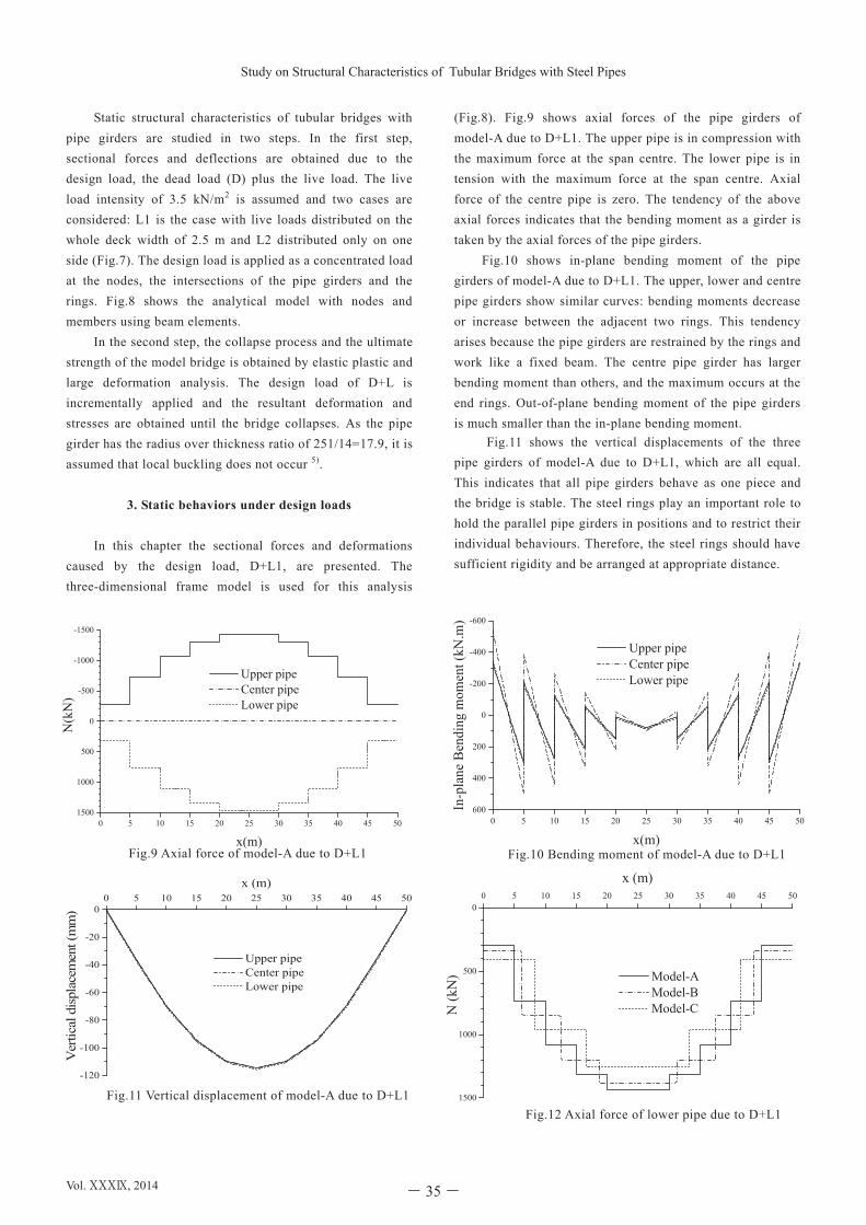
Static structural characteristics of tubular bridges with pipe girders are studied in two steps. In the first step, sectional forces and deflections are obtained due to the design load, the dead load (D) plus the live load. The live load intensity of 3.5 kN/m2 is assumed and two cases are considered: L1 is the case with live loads distributed on the whole deck width of 2.5 m and L2 distributed only on one side (Fig.7). The design load is applied as a concentrated load at the nodes, the intersections of the pipe girders and the rings. Fig.8 shows the analytical model with nodes and members using beam elements. In the second step, the collapse process and the ultimate strength of the model bridge is obtained by elastic plastic and large deformation analysis. The design load of D+L is incrementally applied and the resultant deformation and stresses are obtained until the bridge collapses. As the pipe girder has the radius over thickness ratio of 251/14=17.9, it is assumed that local buckling does not occur 5).
3. Static behaviors under design loads In this chapter the sectional forces and deformations caused by the design load, D+L1, are presented. The three-dimensional frame model is used for this analysis
(Fig.8). Fig.9 shows axial forces of the pipe girders of model-A due to D+L1. The upper pipe is in compression with the maximum force at the span centre. The lower pipe is in tension with the maximum force at the span centre. Axial force of the centre pipe is zero. The tendency of the above axial forces indicates that the bending moment as a girder is taken by the axial forces of the pipe girders.
Fig.10 shows in-plane bending moment of the pipe girders of model-A due to D+L1. The upper, lower and centre pipe girders show similar curves: bending moments decrease or increase between the adjacent two rings. This tendency arises because the pipe girders are restrained by the rings and work like a fixed beam. The centre pipe girder has larger bending moment than others, and the maximum occurs at the end rings. Out-of-plane bending moment of the pipe girders is much smaller than the in-plane bending moment.
Fig.11 shows the vertical displacements of the three pipe girders of model-A due to D+L1, which are all equal. This indicates that all pipe girders behave as one piece and the bridge is stable. The steel rings play an important role to hold the parallel pipe girders in positions and to restrict their individual behaviours. Therefore, the steel rings should have sufficient rigidity and be arranged at appropriate distance.
1500
1000
500
00 5 10 15 20 25 30 35 40 45 50
x (m)
N (k
N)
Model-A Model-B Model-C
Fig.12 Axial force of lower pipe due to D+L1
Fig.10 Bending moment of model-A due to D+L1
-120
-100
-80
-60
-40
-20
00 5 10 15 20 25 30 35 40 45 50
Ver
tical
dis
plac
emen
t (m
m)
x (m)
Upper pipe Center pipe Lower pipe
Fig.11 Vertical displacement of model-A due to D+L1
Fig.9 Axial force of model-A due to D+L1
0 5 10 15 20 25 30 35 40 45 501500
1000
500
0
-500
-1000
-1500
N(k
N)
Upper pipe Center pipe Lower pipe
x(m)
0 5 10 15 20 25 30 35 40 45 50600
400
200
0
-200
-400
-600
In-p
lane
Ben
ding
mom
ent (
kN.m
)
Upper pipe Center pipe Lower pipe
x(m)
Turki JARWALI and Shunichi Nakamura
Proceedings of the School of Engineering Tokai University, Series E
―2―
2500
3300
2500
400400
502
650650 2000
800 4100 800
Fig.4 Cross section
Fig.6 Steel ring with I-section
girders are used to form a hexagonal tubular section with an outside diameter of 5.7 m (Fig.4). The pipe girder is assumed to be 502 mm in diameter and 14 mm in thickness with steel grade of SM490Y 5) (tensile strength of 490 MPa, yield strength of 355 MPa, allowable tensile strength of 210 MPa), as shown in Fig.5. These dimensions are determined by the
allowable stress method so that the stress due to the design load is within the allowable stress. Although the rings are illustrated as a solid shape in Fig.2, the steel I-section is assumed in the design stage from a practical point of view (Fig.6). The steel ring is welded to the steel pipe and the connection is assumed to be rigid in the analysis.
Fig.1 Peace Bridge
Fig.3 Side view of three model bridge (unit: mm)
Fig.7 Live load cases
Fig.5 Steel pipe girder
Fig.2 Tubular Bridge with steel pipes
Fig.8 Analytical model of tubular bridge with steel pipes
10 @ 5,000 = 50,000
8 @ 6,250 = 50,000
6 @ 8,333 = 50,000
2.5
m
1.25
L1
L2
Model – A
Model – C
Model – B
800
746
502
2727
500
Z
Y
Y
Z
502474 14
SM490Y
14
Vol. ⅩⅩⅩⅨ, 2014 - 35-
Study on Structural Characteristics of Tubular Bridges with Steel Pipes

Turki JARWALI and Shunichi Nakamura
Proceedings of the School of Engineering Tokai University, Series E
―4―
The maximum stress of model-A occurs at the upper edge of the centre pipe girder (diameter of 502 mm and thickness of 14 mm) at the end ring. The stress check ratio at this position is a little less than 1.0. In this study the same size steel pipes are used for all the pipe girders.
As the tubular bridge behaves as a beam, the upper and lower pipe girders mainly take bending moment. That is why the upper pipe girder is in compression and the lower pipe
girder is in tension. The centre pipe girder is on the neutral axis and no axial force occurs. On the other hand, bending moment occurs because the pipe girder behaves as a fixed ended beam between the two adjacent rings. The tendency of axial forces and bending moment of the three pipe girders is similar to that of a Vierendeel bridge.
Fig.12 shows axial forces of the lower pipe girders of model-A, B and C due to D+L1. They all show similar curves.
-200
-150
-100
-50
00 5 10 15 20 25 30 35 40 45 50
Ver
tical
dis
plac
emen
t (m
m)
x(m)
Model-A Model-B Model-C
Fig.14 Vertical displacement of center pipe due to D+L1
350
300
250
200
150
100
50
00 5 10 15 20 25 30 35 40 45 50
N (k
N)
x (m)
L1 L2 (Right) L2 (Left)
Fig.15 Axial force of lower pipe of model-A (Live loads)
0 5 10 15 20 25 30 35 40 45 50120
80
40
0
-40
-80
-120
In-p
lane
Ben
ding
mom
ent (
kN.m
)
L1 L2 (Right) L2 (Left)
x (m)Fig.16 Bending moment of center pipe of model-A (Live loads)
-30
-20
-10
00 5 10 15 20 25 30 35 40 45 50
Ver
tical
dis
plac
emen
t (m
m)
x (m)
L1 L2 (Right) L2 (Left)
Fig.17 Vertical displacement of center pipe of model-A (Live load)
Fig.13 Bending moment of center pipe due to D+L1
Fig.18 Bending moment and axial force of end ring of model-A (D+L1)
-322 kN-322 kN --
-189 kN.m-
+
Bending momentAxial force
+
-
161 kN.m
0 5 10 15 20 25 30 35 40 45 50800
600
400
200
0
-200
-400
-600
-800
In-p
lane
Ben
ding
mom
ent (
kN.m
)
Model-A Model-B Model-C
x(m)
Proceedings of the School of Engineering,Tokai University, Series E- 36-
Turki JARWALI and Shunichi NAKAMURA

Structural Characteristics of Tubular Bridgess with Steel Pipes
Vol. XXXI, 2007
―5―
The maximum tension occurs at the mid-span and it is larger in model-A, model-B and model-C in this order, showing that the shorter ring distance causes larger tension.
Fig.13 shows in-plane bending moments of the centre pipe girders of model-A, B and C due to D+L1. They all show similar curves: bending moments decrease or increase between the adjacent two rings. The maximum bending moment occurs near the end ring and it is larger in model-C, model-B and model-A in this order, showing that the longer ring distance causes larger bending moment.
Fig.14 shows the vertical displacements of the three pipe girders of model-A, B and C due to D+L1. The maximum vertical displacement at the mid-span is larger in model-C, model-B and model-A in this order. The ring distance significantly affects the bending stiffness and the longer ring distance causes larger displacement.
It is understood from Figs.12-14 that the maximum bending moments and vertical displacement are larger in model-C, model-B and model-A in this order because the bending stiffness decreases with the ring distance. The axial forces have different tendency. Bending stresses are more dominant than axial stresses and, therefore, the shorter ring distance provides economical pipe sections.
Fig.15 shows axial forces of lower pipe of model-A due to two live load cases, L1 and L2. The axial force due to L2 is half of that of L1. Those of right and left pipe girders due to L2 are not much different, indicating that the eccentric load does not affect much because of the sufficient torsional rigidity.
Fig.16 shows bending moments of the centre pipe girder of model-A due to two live load cases, L1 and L2. The bending moment due to L2 is about half of that of L1. That of the left girder due to L2 is larger than that of the right girder by about 15%.
Fig.17 shows vertical displacements of the centre girder of model-A due to two live load cases, L1 and L2. The displacement due to L2 is about half of that of L1. That of the left girder due to L2 is also larger than that of the right girder by about 15%. The vertical deflection due to live load is 24.4 mm which is within the allowable value of 100 mm (=L/500, L: span length) 4). This confirms that the serviceability of the tubular bridge is satisfied.
It is understood from Figs.15-17 that the effect of eccentricity of live loads is not large within 15% because of sufficient torsional rigidity. The rings play an important role to secure this torsional rigidity.
Fig.18 shows the bending moments and axial forces of the end ring which is larger than other rings. The pipe girders are supported at two bottom nodes. There exist bending moments and axial forces which are resisted by the steel
I-section rings, whose stresses are within the allowable stress.
4. Ultimate strength
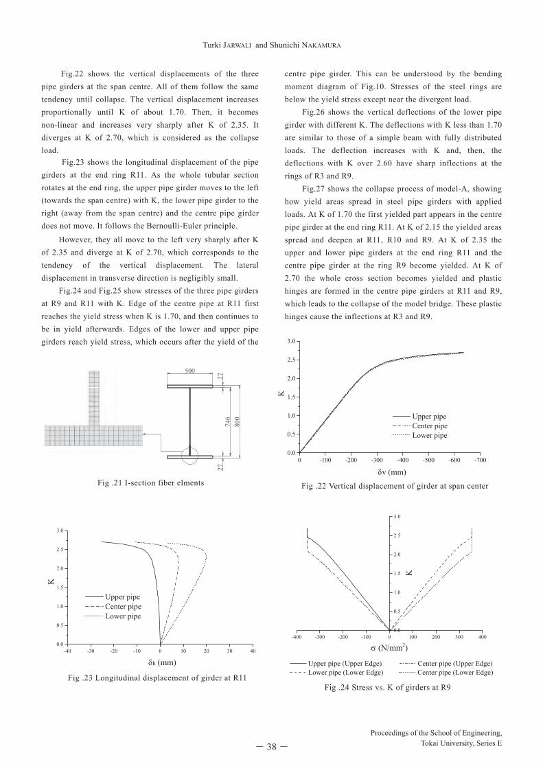
Elastic plastic and large deformation analysis is conducted for the model bridge. Fig.19 shows the assumed stress versus strain relation, an idealized bi-linear curve, for steel pipes and plates with steel grade SM490Y. Yield stress of the steel grade SM490Y is 355MPa. The analytical model is three dimensional, and steel pipe girders and the steel rings are divided into fibre elements. The pipe section is divided into 150 parts in circumferential direction and each part is divided into 5 layers in thickness, as shown in Fig.20. The flange and web of the I-section of the ring is divided into 100 parts and 4 layers for the flange and 2 layers for the web in thickness, as shown in Fig.21. The general purpose FEM program, FRAME/3D (Forum 8), is used for this calculation. The design load D+L is first applied and, then, it is incrementally applied until the model bridge collapses. It is expressed by:
P = K ( D + L ) (1)
where, P: applied load, K: load factor. The increment of the load factor varies depending on the resultant deformation. The minimum load increment factor is set at 0.05.
Fig .20 Steel pipe girder fiber elments
Fig.19 Stress vs. strain (SM490Y)
Stress
Strain
σy
-σy
502474 14
SM490Y
14
Structural Characteristics of Tubular Bridgess with Steel Pipes
Vol. XXXI, 2007
―5―
The maximum tension occurs at the mid-span and it is larger in model-A, model-B and model-C in this order, showing that the shorter ring distance causes larger tension.
Fig.13 shows in-plane bending moments of the centre pipe girders of model-A, B and C due to D+L1. They all show similar curves: bending moments decrease or increase between the adjacent two rings. The maximum bending moment occurs near the end ring and it is larger in model-C, model-B and model-A in this order, showing that the longer ring distance causes larger bending moment.
Fig.14 shows the vertical displacements of the three pipe girders of model-A, B and C due to D+L1. The maximum vertical displacement at the mid-span is larger in model-C, model-B and model-A in this order. The ring distance significantly affects the bending stiffness and the longer ring distance causes larger displacement.
It is understood from Figs.12-14 that the maximum bending moments and vertical displacement are larger in model-C, model-B and model-A in this order because the bending stiffness decreases with the ring distance. The axial forces have different tendency. Bending stresses are more dominant than axial stresses and, therefore, the shorter ring distance provides economical pipe sections.
Fig.15 shows axial forces of lower pipe of model-A due to two live load cases, L1 and L2. The axial force due to L2 is half of that of L1. Those of right and left pipe girders due to L2 are not much different, indicating that the eccentric load does not affect much because of the sufficient torsional rigidity.
Fig.16 shows bending moments of the centre pipe girder of model-A due to two live load cases, L1 and L2. The bending moment due to L2 is about half of that of L1. That of the left girder due to L2 is larger than that of the right girder by about 15%.
Fig.17 shows vertical displacements of the centre girder of model-A due to two live load cases, L1 and L2. The displacement due to L2 is about half of that of L1. That of the left girder due to L2 is also larger than that of the right girder by about 15%. The vertical deflection due to live load is 24.4 mm which is within the allowable value of 100 mm (=L/500, L: span length) 4). This confirms that the serviceability of the tubular bridge is satisfied.
It is understood from Figs.15-17 that the effect of eccentricity of live loads is not large within 15% because of sufficient torsional rigidity. The rings play an important role to secure this torsional rigidity.
Fig.18 shows the bending moments and axial forces of the end ring which is larger than other rings. The pipe girders are supported at two bottom nodes. There exist bending moments and axial forces which are resisted by the steel
I-section rings, whose stresses are within the allowable stress.
4. Ultimate strength
Elastic plastic and large deformation analysis is conducted for the model bridge. Fig.19 shows the assumed stress versus strain relation, an idealized bi-linear curve, for steel pipes and plates with steel grade SM490Y. Yield stress of the steel grade SM490Y is 355MPa. The analytical model is three dimensional, and steel pipe girders and the steel rings are divided into fibre elements. The pipe section is divided into 150 parts in circumferential direction and each part is divided into 5 layers in thickness, as shown in Fig.20. The flange and web of the I-section of the ring is divided into 100 parts and 4 layers for the flange and 2 layers for the web in thickness, as shown in Fig.21. The general purpose FEM program, FRAME/3D (Forum 8), is used for this calculation. The design load D+L is first applied and, then, it is incrementally applied until the model bridge collapses. It is expressed by:
P = K ( D + L ) (1)
where, P: applied load, K: load factor. The increment of the load factor varies depending on the resultant deformation. The minimum load increment factor is set at 0.05.
Fig .20 Steel pipe girder fiber elments
Fig.19 Stress vs. strain (SM490Y)
Stress
Strain
σy
-σy
502474 14
SM490Y
14
Vol. ⅩⅩⅩⅨ, 2014 - 37-
Study on Structural Characteristics of Tubular Bridges with Steel Pipes
Turki JARWALI and Shunichi Nakamura
Proceedings of the School of Engineering Tokai University, Series E
―6―
Fig.22 shows the vertical displacements of the three pipe girders at the span centre. All of them follow the same tendency until collapse. The vertical displacement increases proportionally until K of about 1.70. Then, it becomes non-linear and increases very sharply after K of 2.35. It diverges at K of 2.70, which is considered as the collapse load.
Fig.23 shows the longitudinal displacement of the pipe girders at the end ring R11. As the whole tubular section rotates at the end ring, the upper pipe girder moves to the left (towards the span centre) with K, the lower pipe girder to the right (away from the span centre) and the centre pipe girder does not move. It follows the Bernoulli-Euler principle.
However, they all move to the left very sharply after K of 2.35 and diverge at K of 2.70, which corresponds to the tendency of the vertical displacement. The lateral displacement in transverse direction is negligibly small.
Fig.24 and Fig.25 show stresses of the three pipe girders at R9 and R11 with K. Edge of the centre pipe at R11 first reaches the yield stress when K is 1.70, and then continues to be in yield afterwards. Edges of the lower and upper pipe girders reach yield stress, which occurs after the yield of the
centre pipe girder. This can be understood by the bending moment diagram of Fig.10. Stresses of the steel rings are below the yield stress except near the divergent load.
Fig.26 shows the vertical deflections of the lower pipe girder with different K. The deflections with K less than 1.70 are similar to those of a simple beam with fully distributed loads. The deflection increases with K and, then, the deflections with K over 2.60 have sharp inflections at the rings of R3 and R9. Fig.27 shows the collapse process of model-A, showing how yield areas spread in steel pipe girders with applied loads. At K of 1.70 the first yielded part appears in the centre pipe girder at the end ring R11. At K of 2.15 the yielded areas spread and deepen at R11, R10 and R9. At K of 2.35 the upper and lower pipe girders at the end ring R11 and the centre pipe girder at the ring R9 become yielded. At K of 2.70 the whole cross section becomes yielded and plastic hinges are formed in the centre pipe girders at R11 and R9, which leads to the collapse of the model bridge. These plastic hinges cause the inflections at R3 and R9.
-40 -30 -20 -10 0 10 20 30 400.0
0.5
1.0
1.5
2.0
2.5
3.0
Upper pipe Center pipe Lower pipe
h (mm)
Fig .23 Longitudinal displacement of girder at R11
0 -100 -200 -300 -400 -500 -600 -7000.0
0.5
1.0
1.5
2.0
2.5
3.0
Upper pipe Center pipe Lower pipe
v (mm)
Fig .22 Vertical displacement of girder at span center
-400 -300 -200 -100 0 100 200 300 4000.0
0.5
1.0
1.5
2.0
2.5
3.0
Upper pipe (Upper Edge) Center pipe (Upper Edge) Lower pipe (Lower Edge) Center pipe (Lower Edge)
(N/mm2)
Fig .24 Stress vs. K of girders at R9
Fig .21 I-section fiber elments
800
746
2727
500
Proceedings of the School of Engineering,Tokai University, Series E- 38-
Turki JARWALI and Shunichi NAKAMURA

Structural Characteristics of Tubular Bridgess with Steel Pipes
Vol. XXXI, 2007
―7―
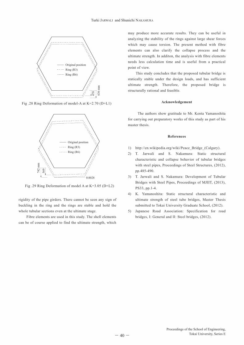
Fig.28 shows the ring deformation of R3 and R6 of model-A due to 2.7*(D+L1), the ultimate loads. There cannot be seen any sign of buckling in the ring. It can be therefore judged that the rings are stable and hold the whole tubular sections even at the ultimate stage.
Fig.29 shows the ring deformation of R3 and R6 of model-A due to 3.05*(D+L2) at the ultimate stage. Although the ring inclines due to the eccentric live loads, its inclined angle is 0.0028 rad which is very small. As there seems no sign of buckling and excessive deformation, the rings are rigid and stable for the eccentric live loads.
5. Conclusion A new type of footbridge, the tubular bridge with steel pipe girders, is proposed and its static behaviours and ultimate strength is studied in this paper. Static behaviours, sectional forces and deflections, are obtained due to the design load. The upper pipe girder is in compression, the lower pipe girder is in tension, and the centre pipe girder has no axial force. Bending moments
decrease or increase between the adjacent two rings. The centre pipe girder has the larger bending moments. The vertical displacements of the three pipe girders are all equal, indicating that all pipe girders behave as a one piece and the bridge is stable. The collapse process and the ultimate strength of the model bridge are obtained by elastic plastic and large deformation analysis. The vertical displacements at span centre increases linearly until K of about 1.70, increases very sharply after K of 2.35, and diverges at K of 2.70. At K of 1.70 the first yielded part appears in the centre pipe girder at the end ring R11. At K of 2.00 the upper and lower pipe girders at the end ring R10 and the centre pipe girder at the ring R8 become yielded. At K of 2.70 the whole cross section becomes yielded and plastic hinges are formed in the centre pipe girders at R11 and R9, which leads to the collapse of the model bridge. These plastic hinges cause the inflections at R3 and R9. The pipe girders are supported at two bottom nodes of the rings. The steel I-section is assumed for the rings. The rings play an important role to hold the bending and torsional
-400 -300 -200 -100 0 100 200 300 4000.0
0.5
1.0
1.5
2.0
2.5
3.0
Upper pipe (Upper Edge) Center pipe (Upper Edge) Lower pipe (Lower Edge) Center pipe (Lower Edge)
(N/mm2)
Fig .25 Stress vs. K of girders at R11
-800
-600
-400
-200
00 5 10 15 20 25 30 35 40 45 50
Ver
tical
dis
plac
emen
t (m
m)
x (m)
K=1.00 K=2.35 K=2.60 K=2.70
Fig .26 Vertical deflection of lower pipe girder of model-A Fig .27 Collapse process of Model-A
Vol. ⅩⅩⅩⅨ, 2014 - 39-
Study on Structural Characteristics of Tubular Bridges with Steel Pipes
Turki JARWALI and Shunichi Nakamura
Proceedings of the School of Engineering Tokai University, Series E
―8―
rigidity of the pipe girders. There cannot be seen any sign of buckling in the ring and the rings are stable and hold the whole tubular sections even at the ultimate stage.
Fibre elements are used in this study. The shell elements can be of course applied to find the ultimate strength, which
may produce more accurate results. They can be useful in analyzing the stability of the rings against large shear forces which may cause torsion. The present method with fibre elements can also clarify the collapse process and the ultimate strength. In additon, the analysis with fibre elements needs less calculation time and is useful from a practical point of view. This study concludes that the proposed tubular bridge is statically stable under the design loads, and has sufficient ultimate strength. Therefore, the proposed bridge is structurally rational and feasible.
Acknowledgement The authors show gratitude to Mr. Kenta Yamanoshita for carrying out preparatory works of this study as part of his master thesis.
References 1) http://en.wikipedia.org/wiki/Peace_Bridge_(Calgary). 2) T. Jarwali and S. Nakamura: Static structural
characteristic and collapse behavior of tubular bridges with steel pipes, Proceedings of Steel Structures, (2012), pp.485-490.
3) T. Jarwali and S. Nakamura: Development of Tubular Bridges with Steel Pipes, Proceedings of MJIIT, (2013), PS33, pp.1-4.
4) K. Yamanoshita: Static structural characteristic and ultimate strength of steel tube bridges, Master Thesis submitted to Tokai University Graduate School, (2012).
5) Japanese Road Association: Specification for road bridges, I: General and II: Steel bridges, (2012).
Fig .28 Ring Deformation of model-A at K=2.70 (D+L1)
Fig .29 Ring Deformation of model A at K=3.05 (D+L2)
0.0028
569
Original positionRing (R3)Ring (R6)
742
mm
470
Original positionRing (R3)Ring (R6)
636
mm
Proceedings of the School of Engineering,Tokai University, Series E- 40-
Turki JARWALI and Shunichi NAKAMURA