study of supercapacitor in the application of power ... · pdf filestudy of supercapacitor in...
TRANSCRIPT
Study of Supercapacitor in the Application of Power Electronics
Yi cheng Zhang, Li Wei, Xiaojun Shen, Haiquan Liang
School of Electronics and Information
Tongji University, Shanghai
4800, Cao’an Road, Shanghai
P.R. China
[email protected], [email protected], [email protected], [email protected]
Abstract: - The purpose of this paper is to carry out a comprehensive study of supercapacitor in the application
of power electronics. According to the practical demand and feasibility of power electronics, the modelling,
voltage management and topology of supercapacitor-based power system have been discussed. Further more, in
order to study the terminal behaviour of supercapacitor and voltage balancing strategy for the application of
power electronics, a test bench based on HP-VEE has been built. The measurements on supercapacitor’s
capacitance, ESR (Equivalent serial resistance) and the consistency of a group of serial supercapacitors,
concerning practical application have been suggested. As an example, Maxwell’s BCAP0120 supercapacitors
have been selected for a 1.5kW hybrid supercapacitor- fuel cell power system. Tests have been carried out and
the results show that the ESR is higher and the capacitance is lower compared with the values supplied by
manufacturers; and the consistency of them is good, thus the voltage initialization strategy can be used for
voltage balancing.
Key-Words: - Supercapacitor, Power Electronics, Voltage-balancing, Capacitance, ESR
1 Introduction Supercapacitor is a kind of electrical energy
storage device. The advantages of supercapacitor are
high power density, high efficiency, fast charging
and discharging speed, long cycle life, wide
operating temperature range and environment
friendly. It has become an ideal option for high-
power applications, such as hybrid power systems,
regenerative energy systems and instantaneous back-
up power source [1-2].
When designing a supercapacitor-based power
system, building a proper model for supercapacitor,
taking the appropriate methodology of voltage
management, choosing a right topology of power
system, and knowing the dynamic terminal
behaviour are very important factors for the
performance of power system. Power electronics
device, such as DC/DC converter, is an
indispensable part for the power system.
In power electronics applications, we concern
more about the dynamic parameters of
supercapacitors for they are often used for high duty
cycle applications. Regarding that parameters on
data sheet supplied by manufacturers are the static
value. Hence, a supercapacitor testing method is
needed in order to test the dynamic characteristic
parameters.
Due to the low cell voltage of supercapacitor
(0.9~3.3V), a series connection of supercapacitor
cells is necessary to obtain higher voltage. However,
the unequal distribution of cell voltage will affect the
performance and lifetime of the cell. Reference [3]
has recommended 37several voltage balancing
strategies. Another way to overcome the problem is
so-called Voltage initialization described by
Okamura [4]. It has yet to be decided that the
consistency of supercapacitors in order to choose a
proper voltage balancing strategy.
The paper has carried out a comprehensive study
of supercapacitor from the view of power
electronics. Methodologies on modelling, voltage
management and topology of supercapacitor-based
power system have been discussed. A test bench
based on HP-VEE has been built. Experiments on
deciding the dynamic behaviour of supercapacitor
and studying the consistency of supercapacitors for
power electronics application have been carried out.
2 Supercapacitor Description 2.1 Principle of EDLC Below the decomposition voltage, while the current
does not flow, an electric double layer occurs at the
boundary of electrode and electrolyte. The electrons
are charged across the double layer and form a
capacitor. Energy is stored in the double-layer
capacitor as charge separation in the double-layer
WSEAS TRANSACTIONS on CIRCUITS and SYSTEMS Yi Cheng Zhang, Li Wei, Xiaojun Shen, Haiquan Liang
ISSN: 1109-2734 508 Issue 6, Volume 8, June 2009
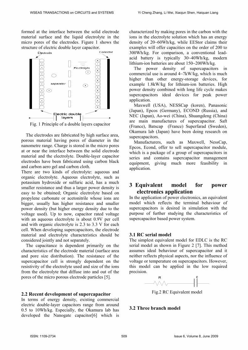
formed at the interface between the solid electrode
material surface and the liquid electrolyte in the
micro pores of the electrodes. Figure 1 shows the
structure of electric double layer capacitor.
Fig. 1 Principle of a double layers capacitor
The electrodes are fabricated by high surface area,
porous material having pores of diameter in the
nanometre range. Charge is stored in the micro pores
at or near the interface between the solid electrode
material and the electrolyte. Double-layer capacitor
electrodes have been fabricated using carbon black
and carbon aero gel and carbon cloth.
There are two kinds of electrolyte: aqueous and
organic electrolyte. Aqueous electrolyte, such as
potassium hydroxide or sulfuric acid, has a much
smaller resistance and thus a larger power density is
easy to be obtained; Organic electrolyte based on
propylene carbonate or acetonitrile whose ions are
bigger, usually has higher resistance and smaller
power density (but higher energy density due to the
voltage used). Up to now, capacitor rated voltage
with an aqueous electrolyte is about 0.9V per cell
and with organic electrolyte is 2.3 to 3.3 V for each
cell. When developing supercapacitors, the electrode
material and electrolyte characteristics should be
considered jointly and not separately.
The capacitance is dependent primarily on the
characteristics of the electrode material (surface area
and pore size distribution). The resistance of the
supercapacitor cell is strongly dependent on the
resistivity of the electrolyte used and size of the ions
from the electrolyte that diffuse into and out of the
pores of the micro porous electrode particles [5].
2.2 Recent development of supercapacitor In terms of energy density, existing commercial
electric double-layer capacitors range from around
0.5 to 10Wh/kg. Especially, the Okamura lab has
developed the Nanogate capacitor[6] which is
characterized by making pores in the carbon with the
ions in the electrolyte solution which has an energy
density of 20~60Wh/kg, while EEStor claims their
examples will offer capacities on the order of 200 to
300Wh/kg. For comparison, a conventional lead-
acid battery is typically 30~40Wh/kg, modern
lithium-ion batteries are about 150~200Wh/kg.
The power density of supercapacitors in
commercial use is around 4~7kW/kg, which is much
higher than other energy-storage devices, for
example 1.8kW/kg for lithium-ion batteries. High
power density combined with long life cycle makes
supercapacitors ideal devices for peak power
application.
Maxwell (USA), NESSCap (koren), Panasonic
(Japan), Epcos (Germany), ECOND (Russia), and
NEC (Japan), Ao-wei (China), Shuangdeng (China)
are main manufactures of supercapacitor. Saft
(France), Batscap (France) Superfarad (Sweden),
Okamura lab (Japan) have been doing research on
supercapacitors.
Manufacturers, such as Maxwell, NessCap,
Epcos, Econd, offer to sell supercapacitor module,
which is a package of a group of supercapacitors in
series and contains supercapacitor management
equipment, giving much more feasibility in
application.
3 Equivalent model for power
electronics application In the application of power electronics, an equivalent
model which reflects the terminal behaviour of
supercapacitors is desired in simulation with the
purpose of further studying the characteristics of
supercapacitor based power system.
3.1 RC serial model The simplest equivalent model for EDLC is the RC
serial model as shown in Figure 2 [7]. This method
assumes ideal behaviour of supercapacitor and it
neither reflects physical aspects, nor the influence of
voltage or temperature on supercapacitors. However,
this model can be applied in the low required
precision.
Fig.2 RC Equivalent model
3.2 Three branch model
WSEAS TRANSACTIONS on CIRCUITS and SYSTEMS Yi Cheng Zhang, Li Wei, Xiaojun Shen, Haiquan Liang
ISSN: 1109-2734 509 Issue 6, Volume 8, June 2009
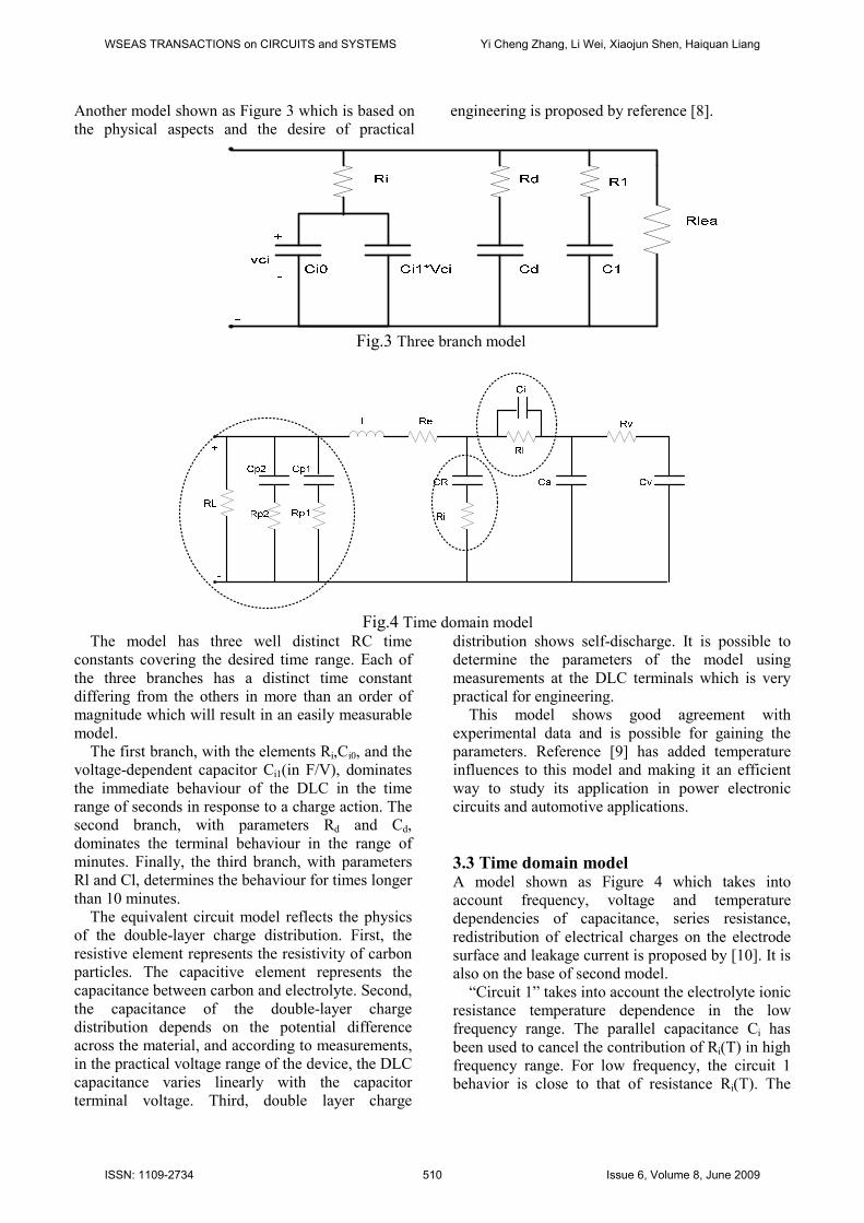
Another model shown as Figure 3 which is based on
the physical aspects and the desire of practical
engineering is proposed by reference [8].
Fig.3 Three branch model
Fig.4 Time domain model
The model has three well distinct RC time
constants covering the desired time range. Each of
the three branches has a distinct time constant
differing from the others in more than an order of
magnitude which will result in an easily measurable
model.
The first branch, with the elements Ri,Ci0, and the
voltage-dependent capacitor Ci1(in F/V), dominates
the immediate behaviour of the DLC in the time
range of seconds in response to a charge action. The
second branch, with parameters Rd and Cd,
dominates the terminal behaviour in the range of
minutes. Finally, the third branch, with parameters
Rl and Cl, determines the behaviour for times longer
than 10 minutes.
The equivalent circuit model reflects the physics
of the double-layer charge distribution. First, the
resistive element represents the resistivity of carbon
particles. The capacitive element represents the
capacitance between carbon and electrolyte. Second,
the capacitance of the double-layer charge
distribution depends on the potential difference
across the material, and according to measurements,
in the practical voltage range of the device, the DLC
capacitance varies linearly with the capacitor
terminal voltage. Third, double layer charge
distribution shows self-discharge. It is possible to
determine the parameters of the model using
measurements at the DLC terminals which is very
practical for engineering.
This model shows good agreement with
experimental data and is possible for gaining the
parameters. Reference [9] has added temperature
influences to this model and making it an efficient
way to study its application in power electronic
circuits and automotive applications.
3.3 Time domain model A model shown as Figure 4 which takes into
account frequency, voltage and temperature
dependencies of capacitance, series resistance,
redistribution of electrical charges on the electrode
surface and leakage current is proposed by [10]. It is
also on the base of second model.
“Circuit 1” takes into account the electrolyte ionic
resistance temperature dependence in the low
frequency range. The parallel capacitance Ci has
been used to cancel the contribution of Ri(T) in high
frequency range. For low frequency, the circuit 1
behavior is close to that of resistance Ri(T). The
WSEAS TRANSACTIONS on CIRCUITS and SYSTEMS Yi Cheng Zhang, Li Wei, Xiaojun Shen, Haiquan Liang
ISSN: 1109-2734 510 Issue 6, Volume 8, June 2009

relationship between Ri and the temperature can be
established from experimental results by using EIS.
“Circuit 2”is introduced to increase the value of
capacitance of the average frequencies. Their
behaviour is the one of a phase shifter.
“Circuit 3” describes the leakage current and the
internal charge redistribution. The self discharge
behaviour of supercapacitors is an important factor
because it determines the duration time of stored
energy on open circuit. The supercapacitor self-
discharge is also a function of temperature. It is
necessary to use two different time constant circuits
RC by elements Rp1Cp1, Rp2Cp2 which depend on the
voltage and on the operating temperature. It also
includes a parallel RL resistance, which gives the
long time leakage current contribution.
It depends on the practical application to decide a
proper model which meets the requirement.
Generally speaking, the RC serial model can be
used in a system with low precision; the three
branch model is fit for the application which has
requirement on dynamic characteristics; while the
time domain model is often used for precise study. It
is suggested that the three branch model is the most
appropriate choice for power electronics
applications.
Fig.5 Passive Balancing
Fig.6 Active Balancing
4 Management of supercapacitor
power systems When connecting many capacitors in series, the
issue of voltage balancing inevitably comes into
play [11]. Basically there are two reasons for an
imbalance of voltages in a serial string of
supercapacitors: (i) deviations from the nominal
capacitance of the capacitors and (ii) deviations in
self discharge performance. While the first topic is
mainly important during dynamic performance of
the capacitor string, the latter topic dominates for
static capacitor performance during constant voltage
phases. A cell management circuit maximizes the
performance and life of supercapacitors installed in
series [12-14].
Generally speaking, there are two ways in voltage
balancing, one is passive balancing, and the other is
active balancing. Another way to overcome the
problem caused by unbalance of voltage is so-called
voltage initialization described by Okamura[4].
4.1 Passive balancing A passive balancing system is designed to
overwhelm the inherent variations in leakage current
by installing a resistor in parallel with each other.
The resistor is typically sized at 10 times the
average leakage current of the cell. The benefits to
this balancing method are simplicity and low cost.
The drawback of this technique is slow response due
to the linearity of leakage current with voltage and
high parasitic losses due to the 10-time additional
leakage current. Passive balancing is mainly used in
low-duty cycle applications such as in backup
power systems. Fig 5 shows a simple balancing
network with resistors.
WSEAS TRANSACTIONS on CIRCUITS and SYSTEMS Yi Cheng Zhang, Li Wei, Xiaojun Shen, Haiquan Liang
ISSN: 1109-2734 511 Issue 6, Volume 8, June 2009

4.2 Active balancing In contrast to passive solutions, an active balancing
circuit behaves nonlinearly and works to force the
cells to have an equal voltage, resulting in the most
effective use of the supercapacitor string. Fig.6
shows a simplified diagram of an active balancing
circuit incorporating a comparator. In this
configuration, each circuit stretches across two cells,
comparing their voltage and moving charge to
equalize the two cells. A number of schemes are
used to achieve active balancing and many are
patented. Active balancing circuit is required in high
duty-cycle applications and where low parasitic
losses are necessary.
4.3 Voltage Initialization The principle of voltage initialization is that all
capacitors are balanced at the upper voltage limit of
the capacitor module. As a consequence, when the
module is discharged, the individual capacitors will
adopt different voltages on a lower level. When
recharged to the upper voltage, all the capacitors
will be balanced again. Provided that the
capacitances of individual capacitors change slowly
with time, an occasional initialization of the module
will keep the capacitors balanced at the upper
working voltage. This is shown by Figure7.
Fig.7 Principle of voltage initialization
This method is much more feasible and less
expensive. Reference [15] has implemented it with
an occasional initialization of all capacitors, which
has achieved a nice result. However, it demands
sound consistency and high quality of
supercapacitor.
5 Topology of supercapacitor energy storage system
The terminal voltage of supercapacitor changes
significantly when being charged or discharged. For
this reason, a power electronics device —DC/DC
converter is necessary to form a supercapacitor
power system [16-18]. The non-isolated Buck-Boost
bidirectional DC/DC converter shown as Figure 8 is
the first choice for that. The advantage of this
topology is high efficiency, high reliability, low
power loss, less expensive and small in size.
Fig.8 Supercapacitor energy storage system
topology This bidirectional Buck-Boost DC/DC converter
allows the power transfer in both directions. This
feature enables the process of charging and
discharging through one unit. The current from the
supercapacitor is fully controlled by bidirectional
DC/DC converter, and the voltage of DC link is
dependent on the control result of it. When charging
the supercapacitor bank, the DC/DC converter
works in Buck mode, and supplies a constant charge
current. The power flows from DC-link to
supercapacitor bank. When discharging, the DC/DC
converter works in Boost mode, and keeps the
voltage of DC-link constant. The power flows from
supercapacitor bank to DC-link.
6 Supercapacitor measurement Regarding that parameters on data sheet supplied by
manufacturers are the static value. In power
electronics applications, we concern more about the
dynamic parameters of supercapacitors for they are
often used for high duty cycle applications. Hence, a
supercapacitor testing method is needed in order to
test the dynamic characteristic parameters.
In this section, a test bench based on HP-VEE has
been built firstly. Then, methods on testing
supercapacitor’s capacitance, ESR (Equivalent
serial resistance) and the consistency of a group of
serial supercapacitors, concerning practical
application have been suggested. As an example,
Maxwell’s BCAP0120 supercapacitors have been
tested for a project which was to build up a hybrid
supercapacitor-fuel cell power system of 1.5kW.
WSEAS TRANSACTIONS on CIRCUITS and SYSTEMS Yi Cheng Zhang, Li Wei, Xiaojun Shen, Haiquan Liang
ISSN: 1109-2734 512 Issue 6, Volume 8, June 2009
6.1Review of testing methods for
supercapacitors Currently, electrochemical impedance spectroscopy
(EIS) and constant current charge and discharge are
two main ways in research of supercapacitors. EIS
is used to characterize electrode material for
supercapacitors in frequency domain, and
professional electrochemical equipment is required
for doing this test [19-21]. However, for power
electronics applications, we concern more about the
terminal behaviour. Hence, constant current charge
and discharge is used for this study.
6.2 Test bench based on HP-VEE The test bench is based on HP-VEE, which is a
graphical programming language optimized for
designing test and measurement applications, and
programs with operator interfaces. Through HP-
VEE, we can design a test procedure; communicate
with test equipment over a general purpose interface
bus (GPIB), and record data of measurements. Table
1 shows the main equipment for building this test
bench.
Table 1: Equipment for building the test bench.
Equipment Parameters
Programmable
DC electronic Load:
Chroma 6310
Current 0~40A,
voltage 0~80V,
resolution 1mA/10mV
Programmable
Power Source :
ITech 6121
Current 0~40A,
voltage 0~80V,
resolution 1mA/10mV
Agilent34970A Data Acquisition Unit,
61/2-digit multimeter
accuracy
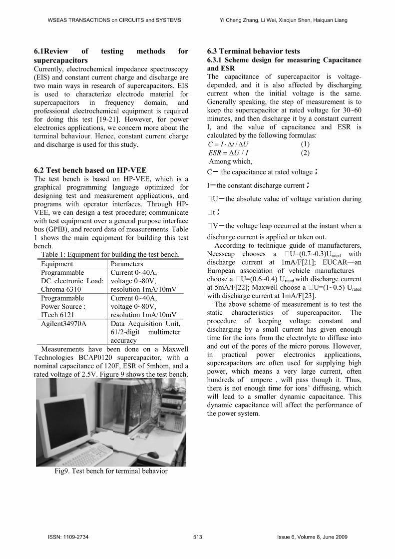
Measurements have been done on a Maxwell
Technologies BCAP0120 supercapacitor, with a
nominal capacitance of 120F, ESR of 5mhom, and a
rated voltage of 2.5V. Figure 9 shows the test bench.
Fig9. Test bench for terminal behavior
6.3 Terminal behavior tests 6.3.1 Scheme design for measuring Capacitance
and ESR
The capacitance of supercapacitor is voltage-
depended, and it is also affected by discharging
current when the initial voltage is the same.
Generally speaking, the step of measurement is to
keep the supercapacitor at rated voltage for 30~60
minutes, and then discharge it by a constant current
I, and the value of capacitance and ESR is
calculated by the following formulas:
UtIC ∆∆⋅= / (1)
IUESR /∆= (2)
Among which,
C- the capacitance at rated voltage;
I-the constant discharge current;
NU-the absolute value of voltage variation during
Nt;
NV-the voltage leap occurred at the instant when a
discharge current is applied or taken out.
According to technique guide of manufacturers,
Necsscap chooses a NU=(0.7~0.3)Urated with
discharge current at 1mA/F[21]; EUCAR—an
European association of vehicle manufactures—
choose a NU=(0.6~0.4) Urated with discharge current
at 5mA/F[22]; Maxwell choose a NU=(1~0.5) Urated
with discharge current at 1mA/F[23].
The above scheme of measurement is to test the
static characteristics of supercapacitor. The
procedure of keeping voltage constant and
discharging by a small current has given enough
time for the ions from the electrolyte to diffuse into
and out of the pores of the micro porous. However,
in practical power electronics applications,
supercapacitors are often used for supplying high
power, which means a very large current, often
hundreds of ampere , will pass though it. Thus,
there is not enough time for ions’ diffusing, which
will lead to a smaller dynamic capacitance. This
dynamic capacitance will affect the performance of
the power system.
WSEAS TRANSACTIONS on CIRCUITS and SYSTEMS Yi Cheng Zhang, Li Wei, Xiaojun Shen, Haiquan Liang
ISSN: 1109-2734 513 Issue 6, Volume 8, June 2009
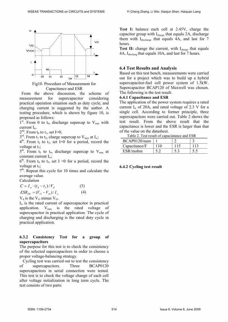
Fig10. Procedure of Measurement for
Capacitance and ESR
From the above discussion, the scheme of
measurement for supercapacitor considering
practical operation situation such as duty cycle, and
charging current is suggested by the author. A
testing procedure, which is shown by figure 10, is
proposed as follows:
1st. From 0 to t0, discharge supercap to Vmin with
current Iw.
2nd. From t0 to t1, set I=0;
3rd. From t1 to t2, charge supercap to Vmax at Iw;
4th. From t2 to t3, set I=0 for a period, record the
voltage at t3;
5th. From t3 to t4, discharge supercap to Vmin at
constant current Iw;
6th. From t4 to t5, set I =0 for a period, record the
voltage at t5;
7th. Repeat this cycle for 10 times and calculate the
average value.
Calculation
dw VttIC /)( 34 −⋅= (3)
wttDC IVVESR /)( 45 −= (4)
Vd is the Vt3 minus Vt5.
Iw is the rated current of supercapacitor in practical
application. Vmax is the rated voltage of
supercapacitor in practical application. The cycle of
charging and discharging is the rated duty cycle in
practical application.
6.3.2 Consistency Test for a group of
supercapacitors
The purpose for this test is to check the consistency
of the selected supercapacitors in order to choose a
proper voltage-balancing strategy.
Cycling test was carried out to test the consistency
of supercapacitors. Three BCAP0120
supercapacitors in serial connection were tested.
This test is to check the voltage change of each cell
after voltage initialization in long term cycle. The
test consists of two parts:
Test I: balance each cell at 2.45V, charge the
capacitor group with Icharge that equals 2A, discharge
them with Idischarge that equals 4A, and last for 7
hours.
Test II: change the current, with Icharge that equals
4A, Idischarg that equals 10A, and last for 7 hours.
6.4 Test Results and Analysis Based on this test bench, measurements were carried
out for a project which was to build up a hybrid
supercapacitor-fuel cell power system of 1.5kW.
Supercapacitor BCAP120 of Maxwell was chosen.
The following is the test result.
6.4.1 Capacitance and ESR
The application of the power system requires a rated
current Iw of 20A, and rated voltage of 2.3 V for a
single cell. According to former principle, three
supercapacitors were carried out. Table 2 shows the
test result. From the above result that the
capacitance is lower and the ESR is larger than that
of the value on the datasheet. Table 2. Test result of capaciatance and ESR
BCAP0120/num 1 2 3
Capacitance/F 110 115 113
ESR/mohm 5.2 5.3 5.5
6.4.2 Cycling test result
WSEAS TRANSACTIONS on CIRCUITS and SYSTEMS Yi Cheng Zhang, Li Wei, Xiaojun Shen, Haiquan Liang
ISSN: 1109-2734 514 Issue 6, Volume 8, June 2009
0 1 2 3 4 5 6 7-0.2
-0.1
0.0
0.1
0.2
∆volt(V)
∆volt(V)
(V1-V3)
(V1-V2)
(V2-V3)
Time(Hour)
∆volt(V)
0 1 2 3 4 5 6 7-0.1
0.0
0.1
0.2
Time(Hour)
0 1 2 3 4 5 6 7-0.2
-0.1
0.0
0.1
0.2
Time(Hour)
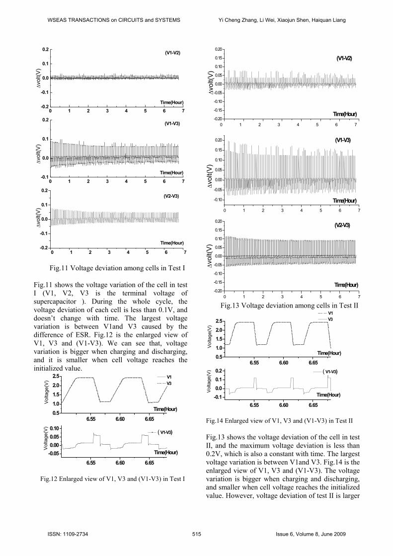
Fig.11 Voltage deviation among cells in Test I
Fig.11 shows the voltage variation of the cell in test
I (V1, V2, V3 is the terminal voltage of
supercapacitor ). During the whole cycle, the
voltage deviation of each cell is less than 0.1V, and
doesn’t change with time. The largest voltage
variation is between V1and V3 caused by the
difference of ESR. Fig.12 is the enlarged view of
V1, V3 and (V1-V3). We can see that, voltage
variation is bigger when charging and discharging,
and it is smaller when cell voltage reaches the
initialized value.
6.55 6.60 6.650.5
1.0
1.5
2.0
2.5
6.55 6.60 6.65
-0.05
0.00
0.05
0.10
Time(Hour)
Voltage(V)
Voltage(V)
Time(Hour)
V1 V3
(V1-V3)
Fig.12 Enlarged view of V1, V3 and (V1-V3) in Test I
0 1 2 3 4 5 6 7
-0.20
-0.15
-0.10
-0.05
0.00
0.05
0.10
0.15
0.20
0 1 2 3 4 5 6 7
-0.10
-0.05
0.00
0.05
0.10
0.15
0.20
0 1 2 3 4 5 6 7
-0.20
-0.15
-0.10
-0.05
0.00
0.05
0.10
0.15
0.20
∆volt(V)
∆volt(V)
∆volt(V)
Time(Hour)
(V1-V2)
Time(Hour)
(V1-V3)
Time(Hour)
(V2-V3)
Fig.13 Voltage deviation among cells in Test II
6.55 6.60 6.650.5
1.0
1.5
2.0
2.5
6.55 6.60 6.65
-0.1
0.0
0.1
0.2
Time(Hour)
Voltage(V)
Voltage(V)
Time(Hour)
V1 V3
( V1-V3)
Fig.14 Enlarged view of V1, V3 and (V1-V3) in Test II
Fig.13 shows the voltage deviation of the cell in test
II, and the maximum voltage deviation is less than
0.2V, which is also a constant with time. The largest
voltage variation is between V1and V3. Fig.14 is the
enlarged view of V1, V3 and (V1-V3). The voltage
variation is bigger when charging and discharging,
and smaller when cell voltage reaches the initialized
value. However, voltage deviation of test II is larger
WSEAS TRANSACTIONS on CIRCUITS and SYSTEMS Yi Cheng Zhang, Li Wei, Xiaojun Shen, Haiquan Liang
ISSN: 1109-2734 515 Issue 6, Volume 8, June 2009

than that of test I, resulted of higher discharging
current.
From the result, we can conclude that the voltage
variation among cells after voltage initialization has
relationship with charge and discharge current and
the initialized voltage. There is no apparently
voltage change in long time cycle, which means the
BCAP0120 supercapacitors show good consistency
during cycling. Hence, an occasional voltage
initialization of all capacitors can be adopted for
voltage management.
7 Conclusion The paper focuses on the study of supercapacitors
for power electronics applications. Methodologies
on modeling, voltage management and topology of
supercapacitor-based power system have been
discussed. A test bench has been built, and the
scheme of measurement for supercapacitor’s
characteristic parameters considering practical
operation situation such as duty cycle, and
discharging current is proposed. Cycling test for
studying the consistency of supercapacitor has also
been carried out. According to the test result,
Maxwell BCAP0120 supercapacitor has shown
good consistency, thus voltage initialization strategy
can be applied in its management.
Acknowledgement
This paper is supported by Chinese National Natural
Science Foundation (No.50877054).
The authors are grateful to the center for energy and
process (CEP) of ecole des mines de Paris (EMP) in
Sophia-Antipolis, France. The author would like to
thank P. Achard, R. Metkemeijer, S. Berthon-Fabry
and P. Leroux for valuable discussions and help
during the study in France.
Reference: [1] P. Thounthong, S. Raël, B. Davat, Fuel cell and
supercapacitors for automotive Hybrid
Electrical system, ECTI Transactions on
Electrical Eng., Electronics, and
Communications, vol.3, No.1, 2005, pp.20-30
[2] A. Rufer, P. Barrade, A supercapacitor-based energy-storage system for elevators with soft
commutated interface, IEEE Transactions on
Industry Applications, Vol.38, 2002, pp.1151-
1159
[3] Dirk Linzen, Stephan Buller, Analysis and evaluation of charge-balancing circuits on
performance, reliability, and lifetime of
supercapacitor systems, IEEE Transactions on
industry applications, Vol.41, No.5, 2005,
pp.1135-1141
[4] M. Okamura, ECaSS: System Improvements &
Discussion, proceedings of the 13th
International Seminar on Double Layer
Capacitors and Hybrid Energy Storage
Devices, 2003, pp.1-12
[5] H. Gualour, D. Bouquain, Experimental study
of supercapacitor serial resistance and
capacitance variations with temperature.
Journal of power sources, Vol.123, 2003 pp.86-
93
[6] M.Okamura, K.Mitsui, Production status of
nanogate capacitors and integrated electronics-
Part I, The 14th international seminar on
double layer capacitors and similar energy
storage devices, 2004, pp.1-8
[7] R.L Spyker, Discharge characteristics of high energy storage double layer capacitors, IECEC-
97, Proceedings of the 32nd Intersociety, Vol 1,
1997, pp.292-296
[8] Luis Zubieta, Richard Bonert, Characterization of double-layer capacitors for power electronics
applications, IEEE transaction on industry
applications, vol.36, 2000, pp.199-205
[9] H.Gualour, D.Bouquain, Experimental study of
supercapacitor serial resistance and capacitance
variations with temperature. Journal of power
sources ,Vol.123, 2003, pp86-93
[10] F.Rafik, H.Gualous, Frequency, thermal and
voltage supercapacitor characterization and
modeling, Journal of power sources,Vol.165,
2007, pp 928-934
[11] N.Rizoug, P.Bartholomeüs, B.Vulturescu,
Voltage sharing in supercapacitor
modules:experimental study, 35th Annual
IEEE power electronics specialists conference,
2004 pp.690-696
[12] D.linzen,S.Buller,E,Karden, Analysis and
evaluation of charge-balancing circuits on
performance, reliability, and lifetime of
supercapacitor systems, IEEE Transactions on
industry applications, Vol.41, No.5, 2005,
pp.1135-1141
[13] R.Kötz, J-C.Sauter, Voltage balancing of a 250 Volt supercapacitor module for a hybrid fuel
cell vehicle, International seminar on double
layer capacitors, 2007, pp.79-86
[14] N.Rizoug, P.Bartholomeüs, Voltage sharing in
supercapacitor modules: experimental study,
WSEAS TRANSACTIONS on CIRCUITS and SYSTEMS Yi Cheng Zhang, Li Wei, Xiaojun Shen, Haiquan Liang
ISSN: 1109-2734 516 Issue 6, Volume 8, June 2009

35th Annual IEEE power electronics specialists
conference, 2004, pp.690-696
[15] R.Kötz, J-C.Sauter, Voltage balancing of a 250 Volt supercapacitor module for a hybrid fuel
cell vehicle, International seminar on double
layer capacitors, 2007, pp.79-86
[16] H.Y.Zhang, T.Z. Wei, Study on ultracapacitor
energy storage. Power system technology,
Vol.30, 2006, pp.92-95
[17] Rufer A, Hotelher D, Barrade P. A
supercapacitor-based energy storage substation
for voltage compensation in weak
transportation networks. Delivery IEEE
Transactions, Vol.19, 2004, pp.629-636
[18] Sng E K K, Choi S Skian, Analysis of series compensation and DC-link Voltage controls of
transformer self-discharging dynamic voltage
restorer. IEEE Transactions on Power Delivery,
Vol.19, 2004, pp.1511-1518
[19] F. Rafik, H.Gualous, Frequency, thermal and
voltage supercapacitor characterization and
modeling, Journal of power sources, Vol.165,
2007, pp.928-934
[20] Eckhard Karden, Stephan Buller, A frequency domain approach to dynamical modeling of
electrochemical power sources, Electrochimica
Acta, Vol.47, 2002, pp.2347-2356
[21] Nesscap ultracapacitor technical guide,
Nesscap Co., Ltd. 2008
[22] P. Kurzweil, B. Frenzel, Capacitance
characterization methods and ageing behaviout
of supercapacitors, The 15th International
seminar on double layer capacitors, 2005
[23] Ultracapacitor product guide, Maxwell Co.,
Ltd. 2008
WSEAS TRANSACTIONS on CIRCUITS and SYSTEMS Yi Cheng Zhang, Li Wei, Xiaojun Shen, Haiquan Liang
ISSN: 1109-2734 517 Issue 6, Volume 8, June 2009