study of lanco 2*600 mw udupi thermal power plant
TRANSCRIPT
1
A
Project Report on
STUDY OF 600MW THERMAL POWER PLANT UDUPI POWER CORPORATION LIMITED 2*600 MW
(LANCO POWER GROUP)
Thermal Power Plant Training Institute
Submitted to Synergem, Nagpur in partial fulfillment for the requirement of
One Year Post Graduate Program in Thermal Power Plant Engineering
During 2013-2014
Submitted By
(KALYANAM SUDHEER KUMAR) (KARTHICK POOBATHI) (SHAFIQUR REEHMAN)
(P. SRINIVAS CHARI)
Under the Esteemed Guidance of
(Mr. C. Pradeep)
AGM Operations
2
A
Project Report on
“STUDY OF 600MW THERMAL POWER PLANT
UDUPI POWER CORPORATION LIMITED 2*600 MW”
Submitted By
(KALYANAM SUDHEER KUMAR) (KARTHICK POOBATHI) (SHAFIQUR REHMAN) (P.SRINIVAS CHARI)
During One Year Post Graduate Program in Thermal Power Plant Engineering
2013-2014
Thermal Power Plant Training Institute
(CEA Recognized)
SYNERGEM

3
“C E R T I F I C A T E”
This is to certify that the project report
“STUDY OF 600MW THERMAL POWER PLANT
UDUPI POWER CORPORATION LIMITED 2*600 MW”
SUBMITED BY
(KALYANAM SUDHEER KUMAR)
(KARTHICK POOBATHI)
(SHAFIQUR REHMAN)
(P.SRINIVAS CHARI)
In the partial fulfillment for the award of
One Year Post Graduate Program in Thermal Power Plant Engineering Nagpur
Session 2013-2014
Mr. Gulshan Sachdev
DIRECTOR SYNERGEM- Thermal Power Plant Training Institute
4
ACKNOWLEDGEMENT
It is an immense pleasure for me to complete the project entitled “Study of THERMAL POWER
PLANT OPERATIONS AND MAINTENANCE”. I express my deep respect & gratitude towards the
invaluable guidance, enormous assistance & excellent cooperation extended to form every corner of the
knowledge.
The word sincere gratitude will not be adequate to express the feelings for my honored mentor Mr.
C. PRADEEP, who has formed the aura to this project. Their benevolent support has blossomed this
endeavor. I thank Mr. Nagraj (HR-HOD), Mr. Gangadhar Sheri (HOD Performance), Maintenance Team and
all the field engineers for their invaluable guidance & inspiration which was constantly provided till the end at
Udupi Power Corporation Limited (2*600 MW)..
Mentee Mentor
(Mr. M.KARTHICK POOBATHI) (Mr. C. PRADEEP)
(Graduate Internship Trainee-Power) (AGM Operations)
(UPCL LANCO Power) (UPCL LANCO Power)

5
DECLARATION
We, the Student of SYNERGEM institute humbly submit that I have completed from time to time the
project work as described in this report by my own skill and study during Semester I as per the guidance of
Mr. C. Pradeep (AGM Operations).
However, the quantum of my contribution has been approved by the mentor and that; I have not copied the
report or its appreciable part from any other literature in the contravention of the academic thesis.
(Name of the students)
M.KARTHICK POOBATHI
K.SUDHEER KUMAR
P.SHRINIVASA CHARI
SHAFIQUR RAHMAN

6
INDEX
SR.NO TOPIC PAGE NO.
1 TECHNICAL SPECIFICATIONS
1.1 Boiler main specifications
1.2 Turbine auxiliaries specifications
(10-18)
10
14
2 SCHEME TRACING
2.1 Auxiliary PRDS
2.2 Deaerator Piping
2.3 Turbine Gland Steam System
2.4 HP LP BY PASS SYSTEM
2.5 Motor Driven Boiler Feed Pump Block Diagram
2.6 HPH Drain System
2.7 LPH Drain System
2.8 Turbine Driven BFP Block Diagram
2.9 Turbine Governing System
2.10 Seal Oil System
2.11 Stator Water Cooling System
2.12 Distribution of Sea Water
2.13 Structure of Bled Steam Water Heater
2.14Design of a 600 MW Dong Fang Make Steam Turbine
2.15 MOT Design and Turbine Jacking Oil System
2.16 Feed Water Cycle
(18-27)
18
19
19
20
20
21
21
22
22
23
23
24
24
25
25
26
7
2.17 Condensate Cycle
2.18 Arrangement of a Compressor House
2.19 Arrangement of TAC & Fluidizing Air Blowers
26
27
27
3
ELECTRICAL SYSTEM IN POWERPLANT
3.1 Steam turbine generator specifications
3.2 Static excitation system
3.3 High voltage switch yard
(28-31)
28
28
30
4
COAL HANDLING PLANT
4.1 Main components of CHP
4.2 Coal mills
4.3 Coal analysis
(32-38)
32
35
36
5 FLUEGAS DESULPHURIATION
(38-39)
6 ASH HANDLING PLANT 6.1 Bottom Ash Handling
6.2 Economizer Ash Handling
6.3 Fly Ash Handling
(40-42) 40
41
41
7 OIL HANDLING PLANT 43
8 SEA WATER INTAKE PUMP HOUSE (43-44)
9 CW AND ACW PUMP HOUSE
9.1 CW pump house
9.2 chlorination plant
9.3 ACW pump house
(44-46)
44
44
45
10 EFFLUENT TREATMENT PLANT (46-47)
11 WATER TREATMENT PLANT & D.M. PLANT (47-51)
12 SAMPLE WATER ANALYSIS SYSTEM 51
13 SINGLE DIAGRAM OF ELECTRICAL SUPPLY SYSTEM (52-54)
8
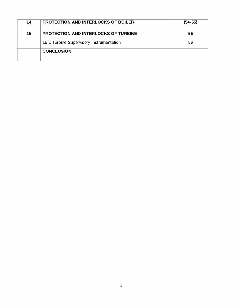
14 PROTECTION AND INTERLOCKS OF BOILER (54-55)
15 PROTECTION AND INTERLOCKS OF TURBINE
15.1 Turbine Supervisory Instrumentation
55
56
CONCLUSION

9
UDUPI POWER CORPORATION LIMITED
Udupi Power Corporation Limited is one of the group companies of LANCO
POWER.
Udupi Power Corporation Limited has established 2*600 MW imported coal
based power project in Udupi District of KarnatakaState in the western coastal
region of India.
The Udupi Power Project supplies 90% of the power generated to Karnataka
state and 10% to Punjab state.
UPCL is the first independent power project using 100% imported coal as fuel in
the company.
UPCL has committed to contribute to reduction of the power shortage in the
state of Karnataka.
10
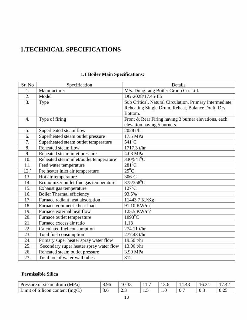
1.TECHNICAL SPECIFICATIONS
1.1 Boiler Main Specifications:
Sr. No Specification Details
1. Manufacturer M/s. Dong fang Boiler Group Co. Ltd.
2. Model DG-2028/17.45-II5
3. Type Sub Critical, Natural Circulation, Primary Intermediate
Reheating Single Drum, Reheat, Balance Draft, Dry
Bottom.
4. Type of firing Front & Rear Firing having 3 burner elevations, each
elevation having 5 burners.
5. Superheated steam flow 2028 t/hr
6. Superheated steam outlet pressure 17.5 MPa
7. Superheated steam outlet temperature 5410C
8. Reheated steam flow 1717.3 t/hr
9. Reheated steam inlet pressure 4.08 MPa
10. Reheated steam inlet/outlet temperature 330/5410C
11. Feed water temperature 2810C
12.` Pre heater inlet air temperature 250C
13. Hot air temperature 3060C
14. Economizer outlet flue gas temperature 375/3580C
15. Exhaust gas temperature 1270C
16. Boiler Thermal efficiency 93.5%
17. Furnace radiant heat absorption 11443.7 KJ/Kg
18. Furnace volumetric heat load 91.10 KW/m3
19. Furnace external heat flow 125.5 KW/m2
20. Furnace outlet temperature 10930C
21. Furnace excess air ratio 1.18
22. Calculated fuel consumption 274.11 t/hr
23. Total fuel consumption 277.43 t/hr
24. Primary super heater spray water flow 19.50 t/hr
25. Secondary super heater spray water flow 13.00 t/hr
26. Reheated steam outlet pressure 3.90 MPa
27. Total no. of water wall tubes 812
Permissible Silica
Pressure of steam drum (MPa) 8.96 10.33 11.7 13.6 14.48 16.24 17.42
Limit of Silicon content (mg/L) 3.6 2.3 1.5 1.0 0.7 0.3 0.25
11
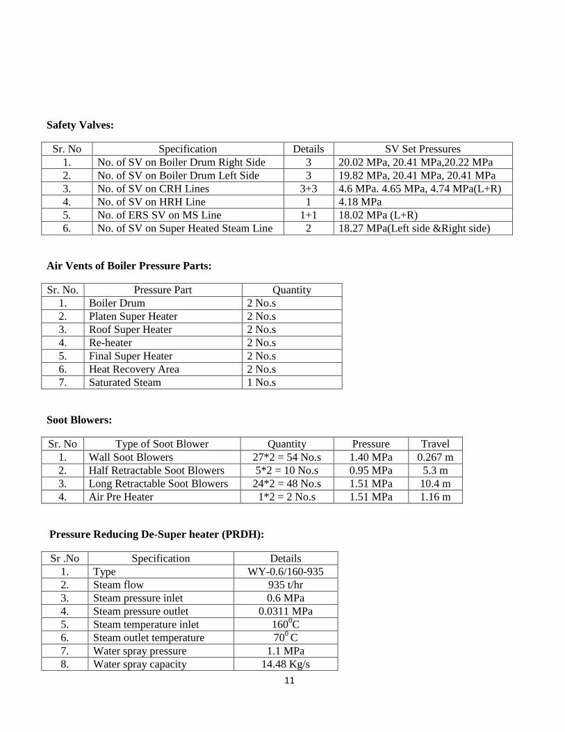
Safety Valves:
Sr. No Specification Details SV Set Pressures
1. No. of SV on Boiler Drum Right Side 3 20.02 MPa, 20.41 MPa,20.22 MPa
2. No. of SV on Boiler Drum Left Side 3 19.82 MPa, 20.41 MPa, 20.41 MPa
3. No. of SV on CRH Lines 3+3 4.6 MPa. 4.65 MPa, 4.74 MPa(L+R)
4. No. of SV on HRH Line 1 4.18 MPa
5. No. of ERS SV on MS Line 1+1 18.02 MPa (L+R)
6. No. of SV on Super Heated Steam Line 2 18.27 MPa(Left side &Right side)
Air Vents of Boiler Pressure Parts:
Sr. No. Pressure Part Quantity
1. Boiler Drum 2 No.s
2. Platen Super Heater 2 No.s
3. Roof Super Heater 2 No.s
4. Re-heater 2 No.s
5. Final Super Heater 2 No.s
6. Heat Recovery Area 2 No.s
7. Saturated Steam 1 No.s
Soot Blowers:
Sr. No Type of Soot Blower Quantity Pressure Travel
1. Wall Soot Blowers 27*2 = 54 No.s 1.40 MPa 0.267 m
2. Half Retractable Soot Blowers 5*2 = 10 No.s 0.95 MPa 5.3 m
3. Long Retractable Soot Blowers 24*2 = 48 No.s 1.51 MPa 10.4 m
4. Air Pre Heater 1*2 = 2 No.s 1.51 MPa 1.16 m
Pressure Reducing De-Super heater (PRDH):
Sr .No Specification Details
1. Type WY-0.6/160-935
2. Steam flow 935 t/hr
3. Steam pressure inlet 0.6 MPa
4. Steam pressure outlet 0.0311 MPa
5. Steam temperature inlet 1600C
6. Steam outlet temperature 700
C
7. Water spray pressure 1.1 MPa
8. Water spray capacity 14.48 Kg/s

12
PA FAN (Axial flow, 2*50%) Specifications:
Sr. No Specification Details
1. Power 2650 KW
2. Stator Voltage 6.6 KV
3. Stator Current 265 A
4. Frequency 50 Hz
5. Power factor 0.904
6. Speed 1493 rpm
7. Stator winding connection 3 phase star connected
8. Impeller Stages 2
9. No. of blades in a stage 24
10. Outlet pressure 11600 Pa (BMCR)
FD Fan (Axial Flow, 2*50%) Specifications:
Sr. No Specification Details
1. Power 2300 KW
2. Stator Voltage 6.6 KV
3. Stator Current 241A
4. Frequency 50 Hz
5. Power Factor 0.864
6. Speed 995 rpm
7. Stator winding connection 3 phase star connected
8. Impeller stages 1
9. No. of blades in a stage 16
10. Outlet pressure 3470 Pa (BMCR)
ID Fan (Axial Flow, 2*50%) Specifications:
Sr. No Specification Details
1. Power 4700 KW
2. Stator Voltage 6.6 KV
3. Stator Current 500A
4. Frequency 50 Hz
5. Power Factor 0.89
6. Speed 747 rpm
7. Stator winding connection 3 phase star connected
8. Outlet pressure 5991 Pa (BMCR)
9. Impeller stages 1
10. No. of blades in a stage 13
13
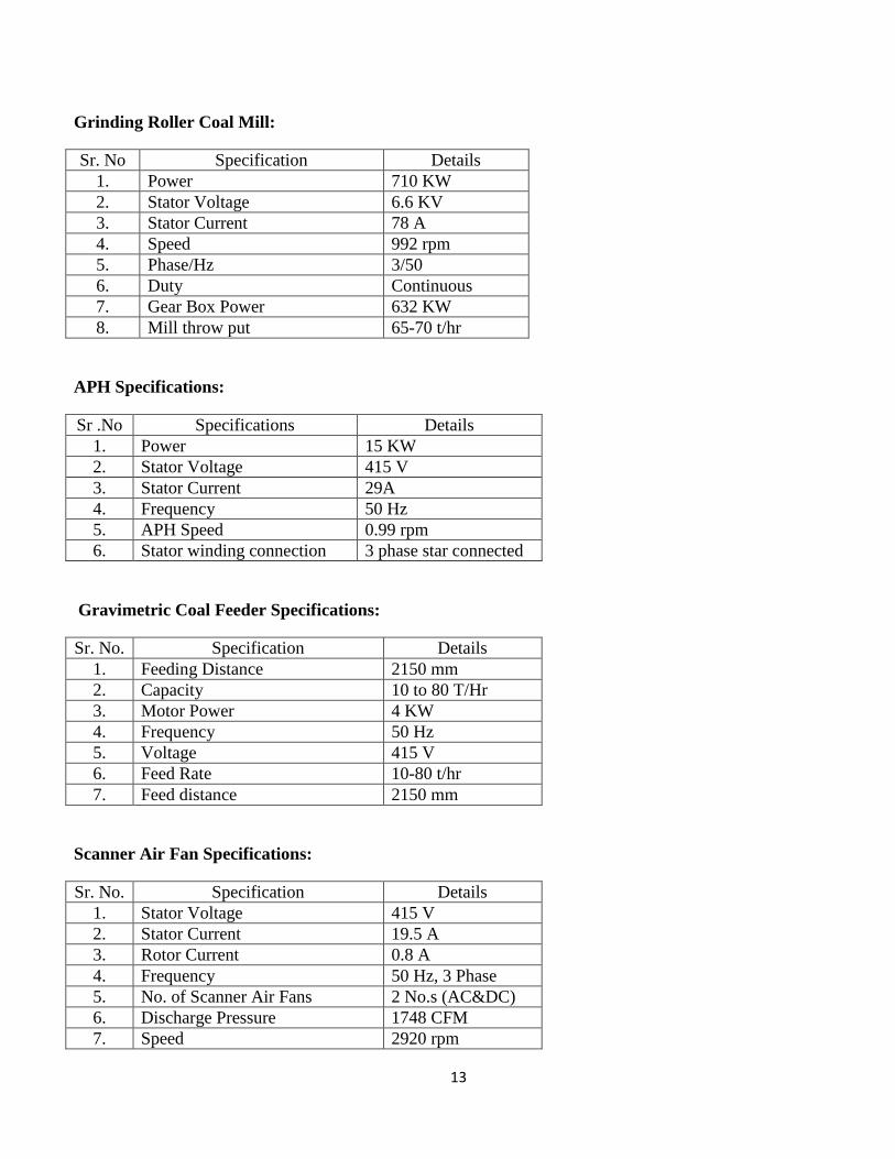
Grinding Roller Coal Mill:
Sr. No Specification Details
1. Power 710 KW
2. Stator Voltage 6.6 KV
3. Stator Current 78 A
4. Speed 992 rpm
5. Phase/Hz 3/50
6. Duty Continuous
7. Gear Box Power 632 KW
8. Mill throw put 65-70 t/hr
APH Specifications:
Sr .No Specifications Details
1. Power 15 KW
2. Stator Voltage 415 V
3. Stator Current 29A
4. Frequency 50 Hz
5. APH Speed 0.99 rpm
6. Stator winding connection 3 phase star connected
Gravimetric Coal Feeder Specifications:
Sr. No. Specification Details
1. Feeding Distance 2150 mm
2. Capacity 10 to 80 T/Hr
3. Motor Power 4 KW
4. Frequency 50 Hz
5. Voltage 415 V
6. Feed Rate 10-80 t/hr
7. Feed distance 2150 mm
Scanner Air Fan Specifications:
Sr. No. Specification Details
1. Stator Voltage 415 V
2. Stator Current 19.5 A
3. Rotor Current 0.8 A
4. Frequency 50 Hz, 3 Phase
5. No. of Scanner Air Fans 2 No.s (AC&DC)
6. Discharge Pressure 1748 CFM
7. Speed 2920 rpm
14
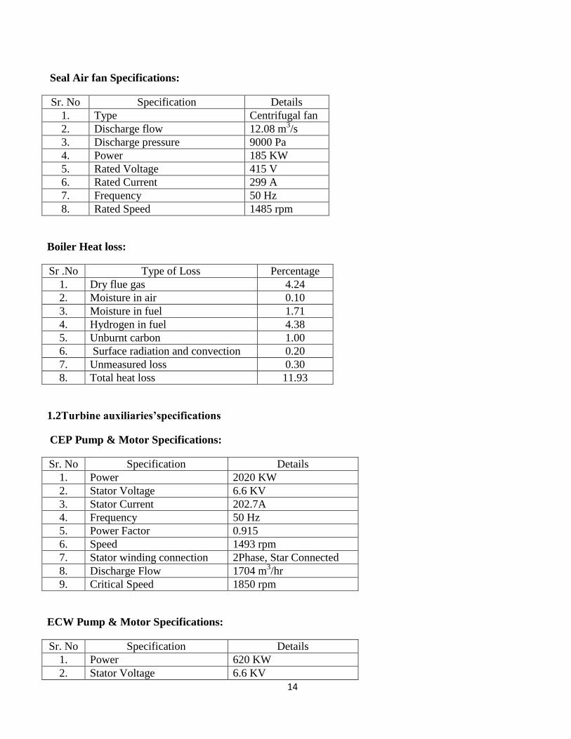
Seal Air fan Specifications:
Sr. No Specification Details
1. Type Centrifugal fan
2. Discharge flow 12.08 m3/s
3. Discharge pressure 9000 Pa
4. Power 185 KW
5. Rated Voltage 415 V
6. Rated Current 299 A
7. Frequency 50 Hz
8. Rated Speed 1485 rpm
Boiler Heat loss:
Sr .No Type of Loss Percentage
1. Dry flue gas 4.24
2. Moisture in air 0.10
3. Moisture in fuel 1.71
4. Hydrogen in fuel 4.38
5. Unburnt carbon 1.00
6. Surface radiation and convection 0.20
7. Unmeasured loss 0.30
8. Total heat loss 11.93
1.2Turbine auxiliaries’specifications
CEP Pump & Motor Specifications:
Sr. No Specification Details
1. Power 2020 KW
2. Stator Voltage 6.6 KV
3. Stator Current 202.7A
4. Frequency 50 Hz
5. Power Factor 0.915
6. Speed 1493 rpm
7. Stator winding connection 2Phase, Star Connected
8. Discharge Flow 1704 m3/hr
9. Critical Speed 1850 rpm
ECW Pump & Motor Specifications:
Sr. No Specification Details
1. Power 620 KW
2. Stator Voltage 6.6 KV
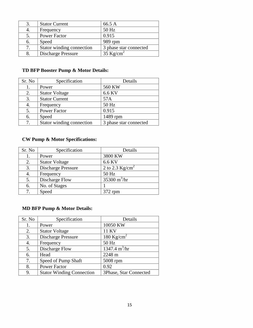
15
3. Stator Current 66.5 A
4. Frequency 50 Hz
5. Power Factor 0.915
6. Speed 989 rpm
7. Stator winding connection 3 phase star connected
8. Discharge Pressure 35 Kg/cm2
TD BFP Booster Pump & Motor Details:
Sr. No Specification Details
1. Power 560 KW
2. Stator Voltage 6.6 KV
3. Stator Current 57A
4. Frequency 50 Hz
5. Power Factor 0.915
6. Speed 1489 rpm
7. Stator winding connection 3 phase star connected
CW Pump & Motor Specifications:
Sr. No Specification Details
1. Power 3800 KW
2. Stator Voltage 6.6 KV
3. Discharge Pressure 2 to 2.3 Kg/cm2
4. Frequency 50 Hz
5. Discharge Flow 35300 m3/hr
6. No. of Stages 1
7. Speed 372 rpm
MD BFP Pump & Motor Details:
Sr. No Specification Details
1. Power 10050 KW
2. Stator Voltage 11 KV
3. Discharge Pressure 180 Kg/cm2
4. Frequency 50 Hz
5. Discharge Flow 1347.4 m3/hr
6. Head 2248 m
7. Speed of Pump Shaft 5008 rpm
8. Power Factor 0.92
9. Stator Winding Connection 3Phase, Star Connected
16
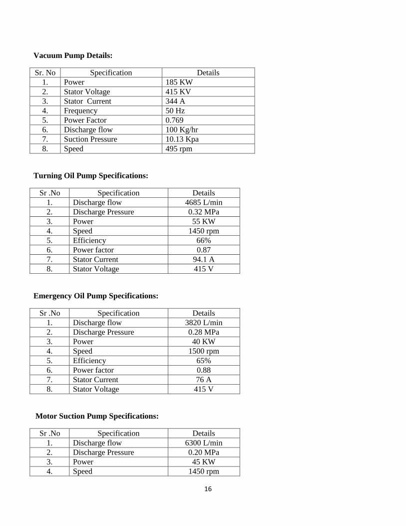
Vacuum Pump Details:
Sr. No Specification Details
1. Power 185 KW
2. Stator Voltage 415 KV
3. Stator Current 344 A
4. Frequency 50 Hz
5. Power Factor 0.769
6. Discharge flow 100 Kg/hr
7. Suction Pressure 10.13 Kpa
8. Speed 495 rpm
Turning Oil Pump Specifications:
Sr .No Specification Details
1. Discharge flow 4685 L/min
2. Discharge Pressure 0.32 MPa
3. Power 55 KW
4. Speed 1450 rpm
5. Efficiency 66%
6. Power factor 0.87
7. Stator Current 94.1 A
8. Stator Voltage 415 V
Emergency Oil Pump Specifications:
Sr .No Specification Details
1. Discharge flow 3820 L/min
2. Discharge Pressure 0.28 MPa
3. Power 40 KW
4. Speed 1500 rpm
5. Efficiency 65%
6. Power factor 0.88
7. Stator Current 76 A
8. Stator Voltage 415 V
Motor Suction Pump Specifications:
Sr .No Specification Details
1. Discharge flow 6300 L/min
2. Discharge Pressure 0.20 MPa
3. Power 45 KW
4. Speed 1450 rpm
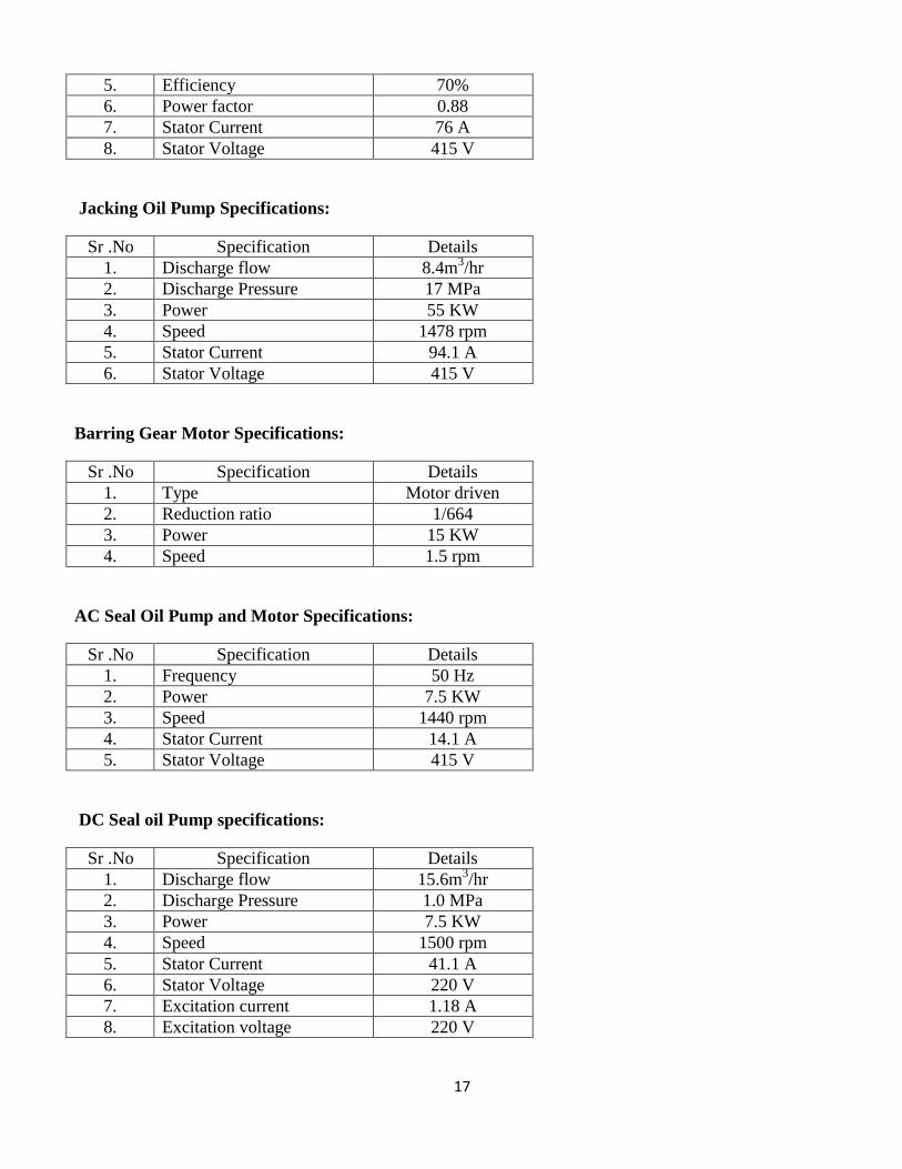
17
5. Efficiency 70%
6. Power factor 0.88
7. Stator Current 76 A
8. Stator Voltage 415 V
Jacking Oil Pump Specifications:
Sr .No Specification Details
1. Discharge flow 8.4m3/hr
2. Discharge Pressure 17 MPa
3. Power 55 KW
4. Speed 1478 rpm
5. Stator Current 94.1 A
6. Stator Voltage 415 V
Barring Gear Motor Specifications:
Sr .No Specification Details
1. Type Motor driven
2. Reduction ratio 1/664
3. Power 15 KW
4. Speed 1.5 rpm
AC Seal Oil Pump and Motor Specifications:
Sr .No Specification Details
1. Frequency 50 Hz
2. Power 7.5 KW
3. Speed 1440 rpm
4. Stator Current 14.1 A
5. Stator Voltage 415 V
DC Seal oil Pump specifications:
Sr .No Specification Details
1. Discharge flow 15.6m3/hr
2. Discharge Pressure 1.0 MPa
3. Power 7.5 KW
4. Speed 1500 rpm
5. Stator Current 41.1 A
6. Stator Voltage 220 V
7. Excitation current 1.18 A
8. Excitation voltage 220 V
18
Critical Speeds of Turbine:
First critical speed R/min Second critical speed R/min
Shafting design value Tandem design value Shafting design value Tandem design value
HIP Rotor 1722 1621 >4000 >4000
LP Rotor A 1839 1723 3521 >4000
LP Rotor B 1903 1750 >4000 >4000
Generator
Rotor
984 1070 >3400 3338
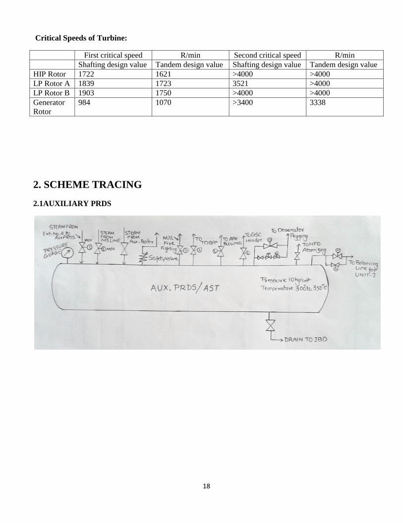
2. SCHEME TRACING
2.1AUXILIARY PRDS
19
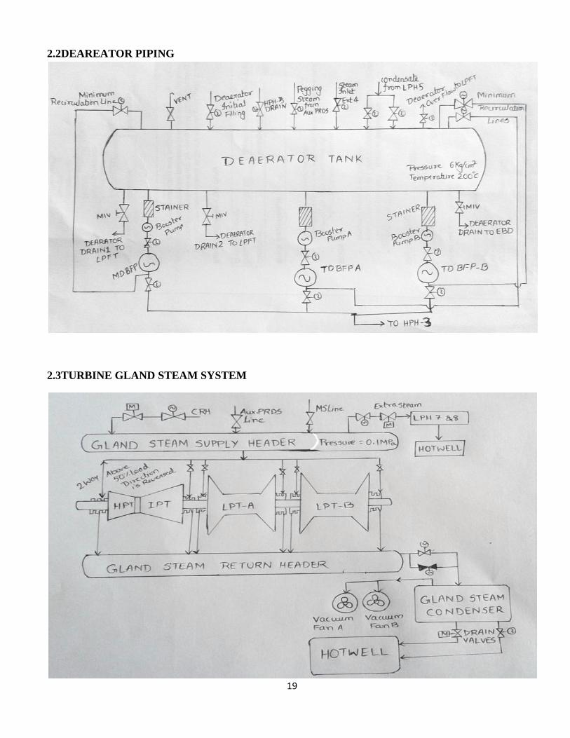
2.2DEAREATOR PIPING
2.3TURBINE GLAND STEAM SYSTEM
20
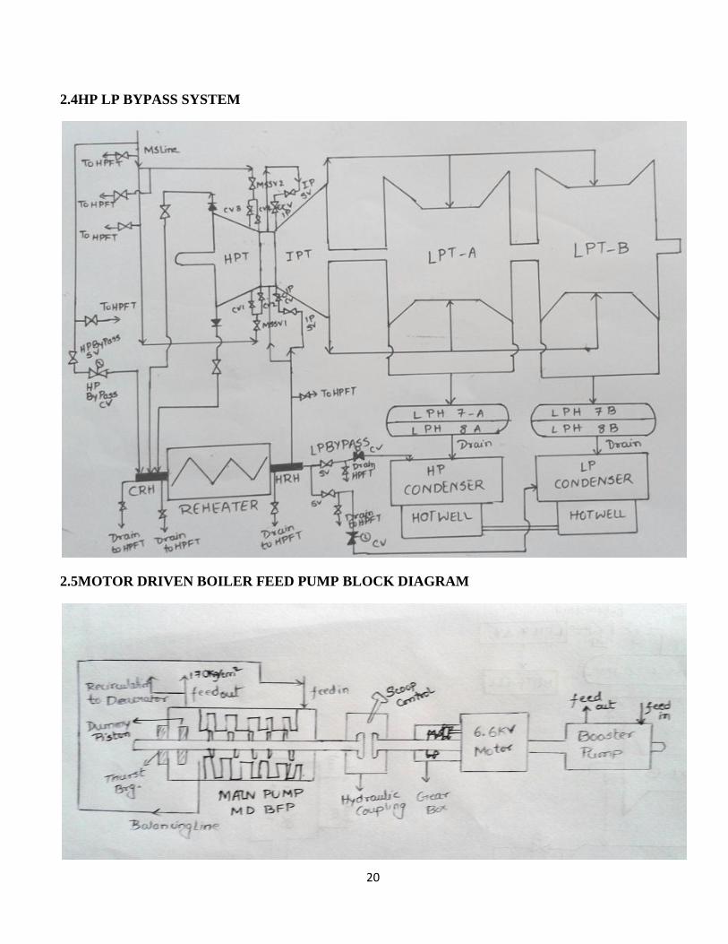
2.4HP LP BYPASS SYSTEM
2.5MOTOR DRIVEN BOILER FEED PUMP BLOCK DIAGRAM

21
2.6HPH DRAINS SYSTEM
2.7LPH DRAINS SYSTEM
22
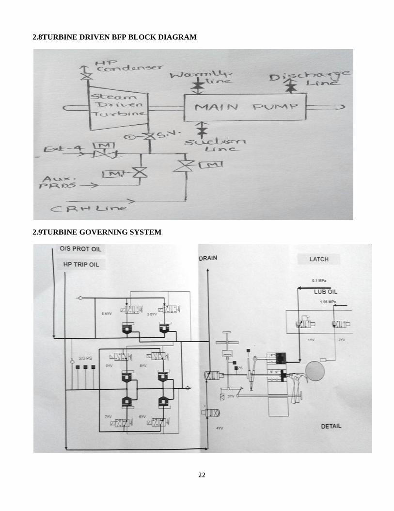
2.8TURBINE DRIVEN BFP BLOCK DIAGRAM
2.9TURBINE GOVERNING SYSTEM
23
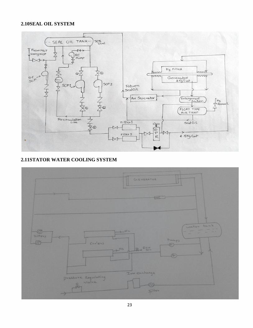
2.10SEAL OIL SYSTEM
2.11STATOR WATER COOLING SYSTEM
24
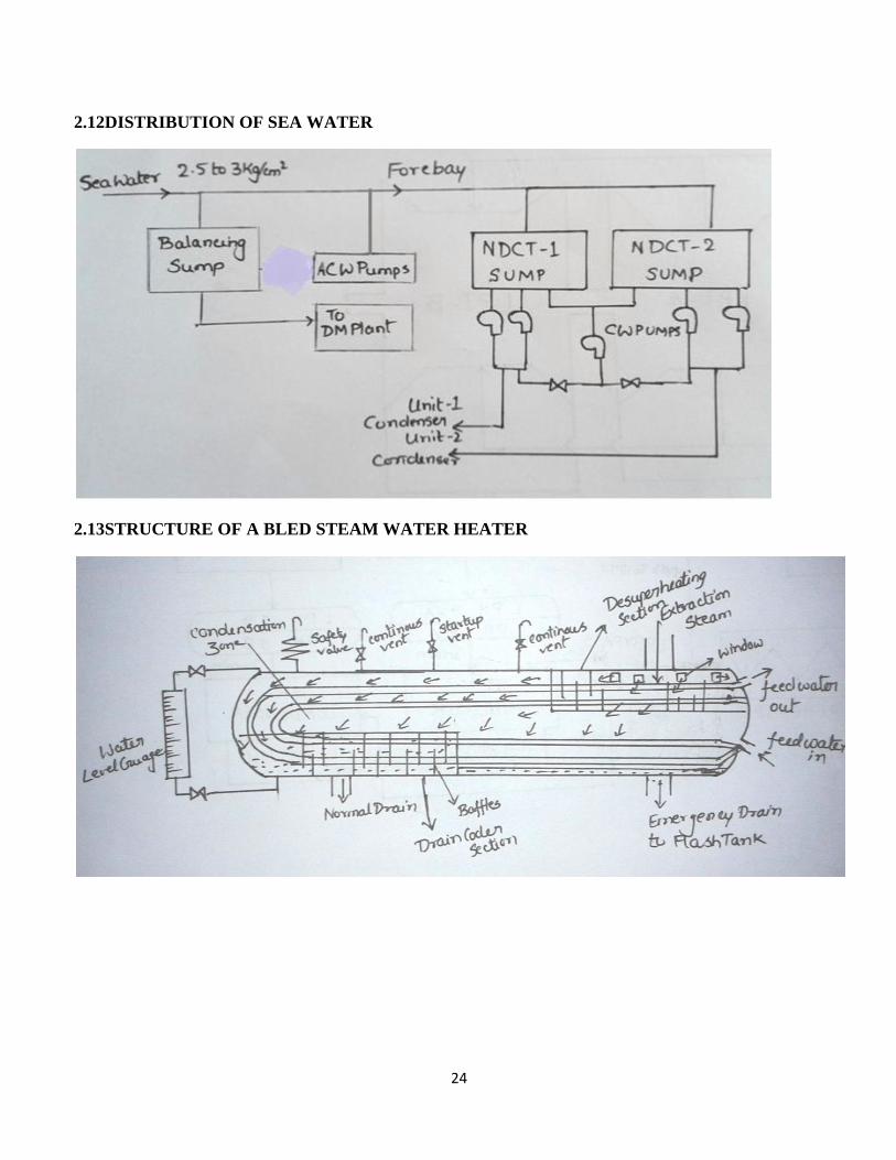
2.12DISTRIBUTION OF SEA WATER
2.13STRUCTURE OF A BLED STEAM WATER HEATER
25
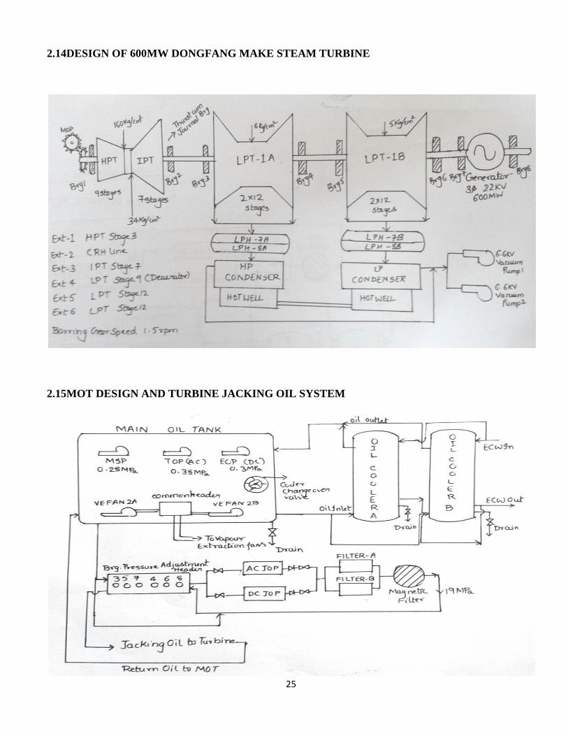
2.14DESIGN OF 600MW DONGFANG MAKE STEAM TURBINE
2.15MOT DESIGN AND TURBINE JACKING OIL SYSTEM
26
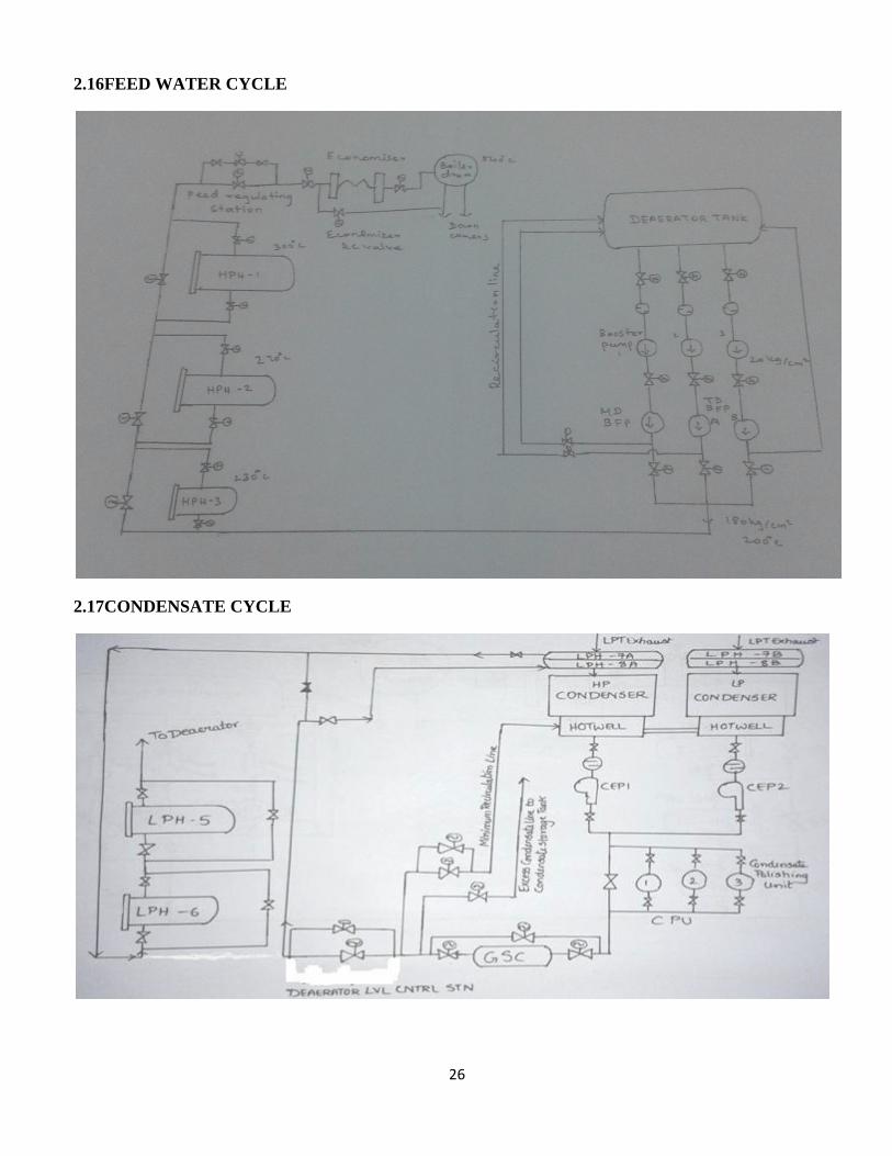
2.16FEED WATER CYCLE
2.17CONDENSATE CYCLE
27
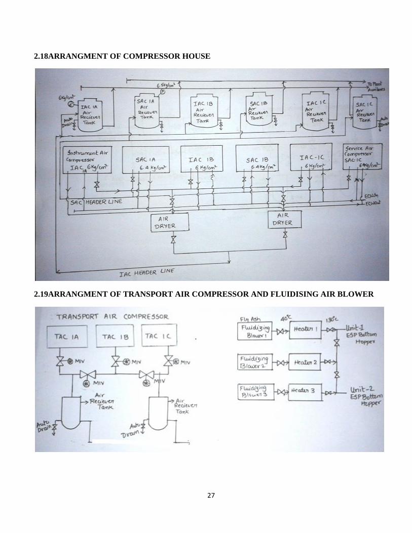
2.18ARRANGMENT OF COMPRESSOR HOUSE
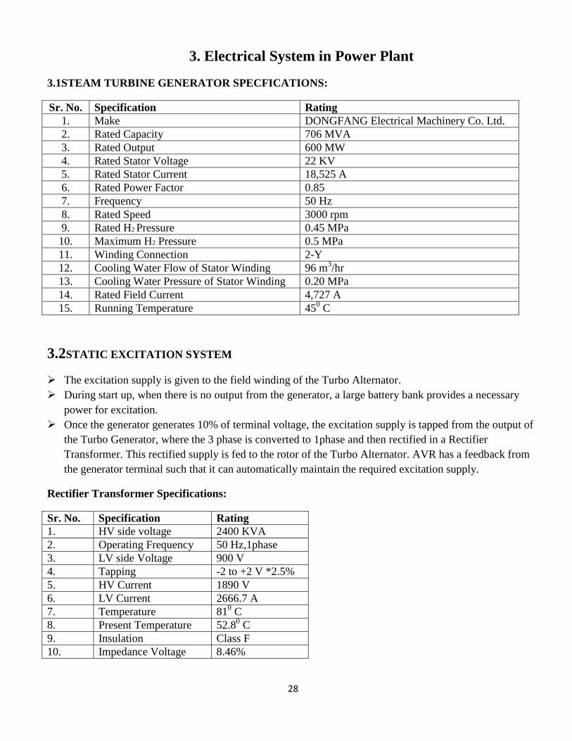
2.19ARRANGMENT OF TRANSPORT AIR COMPRESSOR AND FLUIDISING AIR BLOWER
28
3. Electrical System in Power Plant
3.1STEAM TURBINE GENERATOR SPECFICATIONS:
Sr. No. Specification Rating
1. Make DONGFANG Electrical Machinery Co. Ltd.
2. Rated Capacity 706 MVA
3. Rated Output 600 MW
4. Rated Stator Voltage 22 KV
5. Rated Stator Current 18,525 A
6. Rated Power Factor 0.85
7. Frequency 50 Hz
8. Rated Speed 3000 rpm
9. Rated H2 Pressure 0.45 MPa
10. Maximum H2 Pressure 0.5 MPa
11. Winding Connection 2-Y
12. Cooling Water Flow of Stator Winding 96 m3/hr
13. Cooling Water Pressure of Stator Winding 0.20 MPa
14. Rated Field Current 4,727 A
15. Running Temperature 450 C
3.2STATIC EXCITATION SYSTEM
The excitation supply is given to the field winding of the Turbo Alternator.
During start up, when there is no output from the generator, a large battery bank provides a necessary
power for excitation.
Once the generator generates 10% of terminal voltage, the excitation supply is tapped from the output of
the Turbo Generator, where the 3 phase is converted to 1phase and then rectified in a Rectifier
Transformer. This rectified supply is fed to the rotor of the Turbo Alternator. AVR has a feedback from
the generator terminal such that it can automatically maintain the required excitation supply.
Rectifier Transformer Specifications:
Sr. No. Specification Rating
1. HV side voltage 2400 KVA
2. Operating Frequency 50 Hz,1phase
3. LV side Voltage 900 V
4. Tapping -2 to +2 V *2.5%
5. HV Current 1890 V
6. LV Current 2666.7 A
7. Temperature 810 C
8. Present Temperature 52.80 C
9. Insulation Class F
10. Impedance Voltage 8.46%

29
Generator Excitation Specifications:
Sr .No Specification Details
1. Rated excitation voltage 431 V
2. Ceiling voltage of excitation system 1000V
3. Rated continuous excitation current 4727 A
4. Ceiling voltage for 20 seconds 8986 A
5. Response time 80 ms
6. Excitation Mode DC 220 V
7. Total power consumption of excitation cabinet 58 KW
400KV GT-1 Transformer Details:
Transformer capacity in MVA 250 * 3
Transformer total capacity in MVA 750
HV voltage rating in kV (primary) 420
HV current rating in kA (primary)
LV voltage rating in kV (secondary) 22
LV current rating in kA (secondary)
HV Side CT - primary in Amps 2000
HV Side CT - secondary in Amps 1
LV Side CT - primary in Amps 25000
LV Side CT - secondary in Amps 5
Rated Voltage in Kv 420
Voltage at Maximum tap in kV 441
Voltage at Minimum tap in kV 399
Transformer % Impedance 14.8
OLTC Range = +5% to -5%
Vector Group YNd11
400KV/220KV ICT#1 (R3A&R3B)Transformer Details: Power in MVA 315
HV1 side Voltage in kV 400
HV2 side Voltage in kV 400
LV side Voltage in kV 220
HV1 side CTR Primary in A 2000
HV1 side CTR secondary in A 1
HV2 side CTR Primary in A 2000
% Impedance 0.103
HV2 side CTR secondary in A 1
LV side CTR Primary in A 1600
LV side CTR secondary in A 1
Vector Group YNyn0
OLTC Range 10%
30
STATION TRANSFORMER-1: 220/11.5/6.9 kV, 63 MVA TRANSFORMER Details:
Power 63 MVA
HV side Voltage 220 kV
HV side CT Ratio 1600/1 Amps
LV1 side Voltage 11.5 kV
LV1 side CT Ratio 2500/1 Amp
LV2 side Voltage 6.9 kV
LV2 side CT Ratio 2500/1 Amp
% Impedance 25%
Vector Group YNyn0yn0
3.3High Voltage Switch Yard [400KV & 220KV]
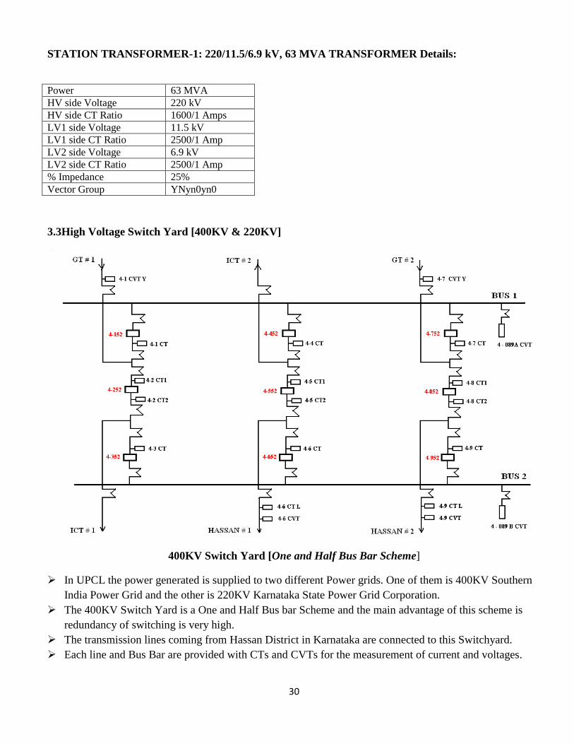
400KV Switch Yard [One and Half Bus Bar Scheme]
In UPCL the power generated is supplied to two different Power grids. One of them is 400KV Southern
India Power Grid and the other is 220KV Karnataka State Power Grid Corporation.
The 400KV Switch Yard is a One and Half Bus bar Scheme and the main advantage of this scheme is
redundancy of switching is very high.
The transmission lines coming from Hassan District in Karnataka are connected to this Switchyard.
Each line and Bus Bar are provided with CTs and CVTs for the measurement of current and voltages.
31
There are no tapping for the station transformer on the 400KV side. The Generator Transformer is not
directly connected with the 220KV switch yard. 400KV switchyard is connected with 220KV switchyard
with a Interconnected Transformer (ICT) which can step up or step down the voltages.
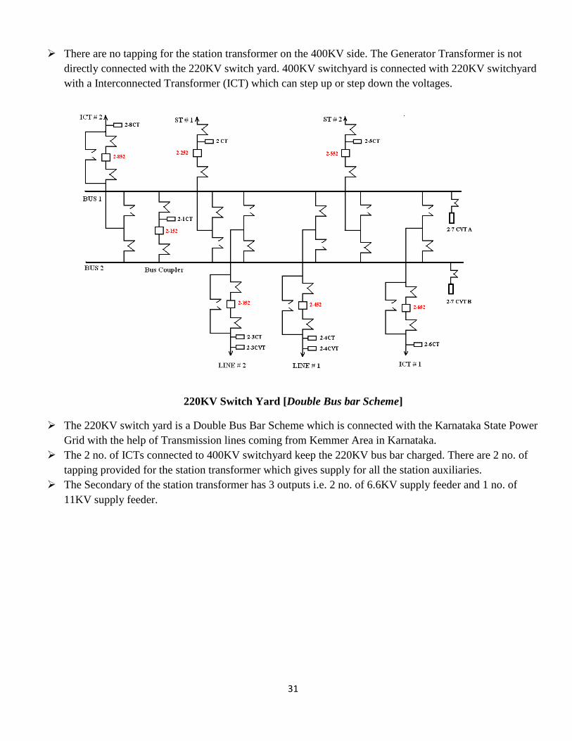
220KV Switch Yard [Double Bus bar Scheme]
The 220KV switch yard is a Double Bus Bar Scheme which is connected with the Karnataka State Power
Grid with the help of Transmission lines coming from Kemmer Area in Karnataka.
The 2 no. of ICTs connected to 400KV switchyard keep the 220KV bus bar charged. There are 2 no. of
tapping provided for the station transformer which gives supply for all the station auxiliaries.
The Secondary of the station transformer has 3 outputs i.e. 2 no. of 6.6KV supply feeder and 1 no. of
11KV supply feeder.
32
4. Coal Handling Plant
Coal handling is most important part of fuel management of a Thermal Power Plant where a lot of money
is invested in purchasing a high quality coal and care to be taken reduce production cost by using a
minimum fuel including transport losses for producing one unit of Power.
In LANCO (Udupi Power Corporation Limited), 2*600 MW, coal is imported from countries like
Indonesia and South Africa through water ways.
For a Cargo ship, it can carry coal up to of 70,000 to 90,000 Tons. In a month, approximately 5 to 6 ships
are unloaded for UPCL Plant. A total of approximately 3.2 to 3.5 lakhs tons of coal is consumed by the
plant in a month.
From New Mangalore Port Trust (NMPT) with the help of Southern Railways and Konkan Railways, the
coal is transported to the plant by Bogie Bottom Open Rapid Discharge Railway wagons.
4.1MAIN COMPONENTS OF CHP
Track Hopper:
It is a place where coal is unloaded from railway wagons. Here bottom discharge box type is
used. It has Pneumatic cylinder which requires an air pressure of 6.3 bar for opening and closing of
bottom doors of the wagon. This air pressure is supplied by air compressors present beside the track
hopper. 6 trains are unloaded in a day.
Capacity of Track hopper = 4000 Tons
Speed of conveyer = 2.9 m/s
Total no. of crushers = 20
Capacity of each bunker = 660T/hr
Total no. of Junction towers = 9
Conveyor Belt capacity = 1000T/hr
Paddle Feeder:
There are 2 no’s of paddle feeder in order to feed coal to two conveyor belts 1A and 1B from
the track hopper. The paddle feeder has got a load to measure the flow of coal. This can be adjusted
by the operator to control the flow of coal of conveyor belt.
33
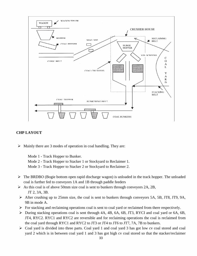
CHP LAYOUT
Mainly there are 3 modes of operation in coal handling. They are:
Mode 1 - Track Hopper to Bunker.
Mode 2 - Track Hopper to Stacker 1 or Stockyard to Reclaimer 1.
Mode 3 - Track Hopper to Stacker 2 or Stockyard to Reclaimer 2.
The BRDBO (Bogie bottom open rapid discharge wagon) is unloaded in the track hopper. The unloaded
coal is further fed to conveyors 1A and 1B through paddle feeders
As this coal is of above 50mm size coal is sent to bunkers through conveyors 2A, 2B,
JT 2, 3A, 3B.
After crushing up to 25mm size, the coal is sent to bunkers through conveyors 5A, 5B, JT8, JT9, 9A,
9B in mode A.
For stacking and reclaiming operations coal is sent to coal yard or reclaimed from there respectively.
During stacking operations coal is sent through 4A, 4B, 6A, 6B, JT3, RYCI and coal yard or 6A, 6B,
JT4, RYC2. RYC1 and RYC2 are reversible and for reclaiming operations the coal is reclaimed from
the coal yard through RYC1 and RYC2 to JT3 or JT4 to JT6 to JT7, 7A, 7B to bunkers.
Coal yard is divided into three parts. Coal yard 1 and coal yard 3 has got low cv coal stored and coal
yard 2 which is in between coal yard 1 and 3 has got high cv coal stored so that the stacker/reclaimer

34
can get easy access of both coal yard 1 and coal yard 2. There are 2 no’s of stacker/reclaimer for the
coal yard.
There are 6 no’s of bunkers for each unit in which under full load 5 bunkers will be under operation.
The coal is fed to the bunkers through the travelling tipplers.
Layout of CHP in UPCL (2*600 MW)
CRUSHER HOUSE
3A, 3B conveyors belt coal to the top of the crusher house >50mm. For this purpose a HT motor is
used of 11 KV. It is further connected to driving pulley through scoop mechanism.
The coal enters through the ILMS where the iron pieces are removed and thrown out of the conveyer
belt from the coal.
Another set of ILMS is present at JT7. Pent house contains metal detector which detects metal parts.
4A and 4B are reversible belt and can be used for both bunkering and stacking operations.
STACKER/RECLAIMER
LANCO UPCL Plant has got 2 no’s of stacker/reclaimer one between CY1, CY2 and the other
between CY2 and CY3.
35
The RYC1 and RYC2 has got 2 no’s of LT motors at their ends running at exact equal speed.
In case of stacking operation, the RYC1 is coal is lifted up into the machine then to intermediate
conveyor and then to boom conveyor and then to coal yard. In this case, the bunkers remain idle.
In case of reclaiming operations, the coal from coal yard if lifted by rotating buckets in the coal heap
and coal is cut in benches. The coal heap can be trapezoidal or conical. The coal lifted by the buckets
fall down on the boom conveyors and then transferred to RYC1 and RYC2.
In order to life the boom Hydro power pack luff is provided. The portion of RYC1 where it bends and
moves upwards into the machine SR is called Trippler Conveyor.
RYC1 and RYC2 is also called Long Travel conveyor.
Vibration feeder is provided below the chute.
To move the sleeve right or left, sleeve drive is provided and it is rotated by 2 no’s sleeve wheels
using 2no’s of meters.
ELECTRICAL MOTORS USED IN STACKER/RECLAIMER
Bucker wheel 75 KW ABB
Intermediate conveyor motor 55 KW ABB
Boom Conveyor motor 55 KW, ABB
Vibro feeder motor 22 KW, ABB
Long travelling motor 5.5 KW, ABB
And dry type Transformer of 11KVA/50KVA is used.
COAL FEEDER AND BUNKERS
The coal comes to the bunkers through long conveyors 8A, 8B and these conveyors are again driven by
HT motors of 11KV.
The coal is then enters the bunkers through conveyors 9A, 9B. The travelling tippler fills the bunkers as
per requirement.
In this plant, each unit has got 6 bunkers. Capacity of bunker is 660 tones.
From the bunker, coal is fed to coal mill through gravity metric coal feeder.
For removing coal dust, the top of the bunkers are provided with Dust Extraction System and exhaust
fans.
4.2COAL MILLS:
There are 6 no. of coal mills provided for each unit out namely A, B, C, D, E & F of which 5 of them will
be running at full load and 1 will be in standby. Mills A, B, F are connected to the rear side of the furnace
and C, D, E are connected to the front side of the furnace. The mills are of Bowl & Roller type mills
which has a through put of 65 to 70 tons per hour. The fineness of the coal mill is 70% of 200 meshes.
There are 2 air inlets for the coal mill i.e., hot air inlet tapped after APH and cold air inlet tapped before
APH. The function of cold air inlet is to maintain mill temperature in between 70 to 800C. Both of the
cold air inlet and hot air inlet is damper controlled.
36
The coal enters the mill from the feeder through a central shaft pipe. The powdered coal mixes with the
hot air is provided by PA fan and rises up through a clarifier where heavier coal particles again fall down
into the bowl of the mill. There are 5 outlet pipe which carry to the coal elevations.
The coal mills have 3 inlets for seal air provided by the 2 no. of seal air fans for each unit. The guide
bearing, support bearing and gear box are sealed by seal air which acts as a protection by restricting the
coal to enter inside gear box and bearings.
The lube oil of each mill is cooled by oil coolers provided for each mill.
SAFETY SYSTEMS AND EMERGENCY
Pull Chord:
In case of emergency or hazard, pull chord can be operated by the operator to immediately
stop the conveyor. Pull chord wire runs throughout the conveyor.
Belt sway switch:
If the belt is running out of axis, it is sensed by the Belt Sway switch and the belt is stopped.
Zero speed switch:
Zero speed switches sends a pulse signal depending upon the speed of the conveyor. If the
speed of conveyor is zero due to any reason, the zero speed gets activated and trips the machine.
Since coal is a combustible element, it can easily catch fire. Auto fire detection systems are provided
through out the conveyor belt which is provided with a cable wire. If the cable wire burns, then the water
immediately flushes through the pipe and extinguish the fire.
4.3COAL ANALYSIS
GCV of Indonesian coal is 5400 to 6400 kcal/kg.
UPCL requires 6000 tons per day to produce 600MW of Power for each unit.
Indonesian coal has a moisture content of 15%. Ash content of 2 to 12%. Volatile Matter 40%.
There are 2 types of analysis of coal a) Proximate analysis
b) Ultimate analysis
Ultimate analysis is not done in the plant. It is to be done before setting up of the plant as the capacity
and structure of the plant.
a) Proximate analysis: Proximate analysis of coal is done to find
1) Total Moisture
2) Ash
3) Carbon fixed
4) Volatile matter
5) GCV of coal
37
b) Ultimate analysis: In this analysis we fine the percentage of Calcium, Sulphur, Nitrogen, Hydrogen
and Oxygen.
Sample coal of around 350KG with total moisture is taken and mill to a size of 12mm and put into a cone
and when coal takes the structure of cone, the cone is removed and the coal is flattened from above so
that it takes the shape of a circle.
The circle is made into 4 quadrants. The top and the bottom quadrant are again taken as sample. This
sample is again milled to a size of 2.5mm and a sample 500gms with total moisture is taken. It is heated
up to 105+2 or 105-2 to find out total moisture.
Take 1kg of coal and dry it for 24 hours at room temperature. This coal should pass through 200micron
mesh at least for 300gm to 400gm.
FC = 100- (IM + VM + ash)
COAL LABORATORY
The coal analysis is done on two bases
1) As received basis
2) As air dried basis
And samples are taken at NMPT, Coal yard and Bunker
Only Proximate analysis is carried out here and the percentages of Ash, Internal Moisture and volatile
matter are found out here.
Internal Moisture:
Gross weight 34.800 gms + 10 gms = 44.82 gms
This 44.82 gms of coal is heat at 105 deg C to 106 deg C for 2 hours in hot air oven.
Ash:
Silica dish weight 26.88gm+1.00gm=27.892gm
This 27.892gm of coal is heated up to 750degc for 1 hour in muffler furnace Metal dish with cap
49.44gm+1.0gm =59.443 gm. This 59.443gm is heated at 900degc for 7 minutes in muffler furnace.
Now let us assume W1, W2, W3 which are the dish weight, dish weight with sample weight and the
final weight after burning/burning respectively.
Now,
Internal moisture% = W2-W1/W2-W3*100
Ash% = W2-W1/W3-W1*100
FC = 100-(IM+VM+Ash)
The IM, ash and VM of coal sample can be calculated combined using automatic multiple thermo
gravimetric analyzers. GCV is found using Bomb calorimeter.
Ash sample is taken before ESP and 1gm of sample is heated at 750degc for 1 hour. For shift two
samples are taken. The sample formula mentioned above is used to find the ash%.
Flue gas sample is titrated with KOH for detect CO2% and pyrogalol to detect O2%. Generally CO will
be 15% and O2 will be 5 to 6%.
38
Calorimeter result:
Weight-1.0080gm
Sulphur-0.80
Initial temp-25.83
Jacket temp-29.99
EE value-2397.5
Spike weight-0.00
Acid-10.00
Gross Heat-6167.74 cal/g
5. FLUE GAS DESULPHURIZATION
One of the major constituents of flue gas is Sulphur oxides and Nitrous oxides. Sulphur oxides when
mixes with moisture in air below dew point (around 100degc) it forms H2SO4 .
The Sox, NOx when reacts with atmosphere, it may pollute the atmosphere.
In order to prevent this happening both the units of UPCL are installed with Desulphurization plant
which remove sulphur from the flue gas not completely but to acceptable limits.
The desulphurization plant mainly consists of a scrubber units of 2 no’s technically called as absorber.
Absorbers are connected through a duct to the main flue gas path after the ID fans and before the
chimney.
Booster fans are connected in parallel to the flue gas path to absorb part of the flue gas from which
sulphur is removed. Booster fans have got blade pitch control to control the flow of flue gas to absorber.
The absorber units are provided with limestone storage tanks. Limestone is basic in nature; it reacts with
sulphur which is acidic in nature and neutralizes forming Gypsum. CaCO3 + SO2------------CaSO3+CO2
½ 02+CaSO3+2H20-----------CaSO4+2H2O

39
In the absorber, limestone powder has to be fed from the top of it, but limestone is received in the form of
solid lumps which has to be crushed.
VFD weigh Belt feeder is provided below the limestone silo in order to weigh the lime consumption.
After the belt weight feeder the lime stone falls on a reversible belt where it can be fed to ball mill 1 or 2.
Hydro cyclone works on the principle of cyclone precipitators where heavy particles settle down and
lighter particles raises upwards.
After hydro cyclone, the lime slurry with water in the slurry recirculation tank and this slurry water is fed
to the absorber which falls down the top and flue gas enters from the bottom.
Agitations are provided at the bottom of the absorber to provide thorough mixing of flue gas with lime
slurry.
Oxidation blowers are provided to give extra O2 to form gypsum and to remove air from gypsum. The
gypsum formed at the bottom of absorber is in liquid state and to make it to solid state vacuum belt fitter
are provided.
Temperatures inside the absorber are continuously monitored. Temperature should not exceed above
100degc as the internals of the absorber are made up of rubber. If temperature exceeds above normal
level, water is flushed through quenching spray to reduce temperatures.
Density of limestone after ball mill should be 1.02 to 1.12kg/cm3 and PH of lime is in between 5.5 to 6.5.
40
6. ASH HANDLING PLANT
6.1BOTTOM ASH HANDLING
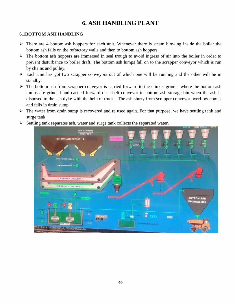
There are 4 bottom ash hoppers for each unit. Whenever there is steam blowing inside the boiler the
bottom ash falls on the refractory walls and then to bottom ash hoppers.
The bottom ash hoppers are immersed in seal trough to avoid ingress of air into the boiler in order to
prevent disturbance to boiler draft. The bottom ash lumps fall on to the scrapper conveyor which is run
by chains and pulley.
Each unit has got two scrapper conveyors out of which one will be running and the other will be in
standby.
The bottom ash from scrapper conveyor is carried forward to the clinker grinder where the bottom ash
lumps are grinded and carried forward on a belt conveyor to bottom ash storage bin when the ash is
disposed to the ash dyke with the help of trucks. The ash slurry from scrapper conveyor overflow comes
and falls in drain sump.
The water from drain sump is recovered and re used again. For that purpose, we have settling tank and
surge tank.
Settling tank separates ash, water and surge tank collects the separated water.

41
6.2 ECONOMIZER ASH HANDLING:
After Economizer, there is a bend in duct of the boiler furnace and then flue gas goes to air pre heater.
As ash travelling in this path and due to a sudden change in its path, the ash tries to settle down due to
gravity.
At this path, 7 hoppers are provided for each unit to collect economizer ash.
Each economizer hopper is provided with a manual gate and solenoid gate to open and close. The
hopper’s end is enclosed in a seal trough to avoid ingress of air into boiler furnace to avoid disturbance to
boiler furnace.
The economizer ash reaches the scrapper conveyor where the next process is all same as in the case of
bottom ash handling. After seal trough the economizer ash is sprinkled with water in the flushing
apparatus.
6.3 FLY ASH HANDLING
Fly ash is totally collected in “Electro static precipitator”. The ESP contains a cathode and anode in every
field which are supplied with a DC voltage of 60KV.
When the ash particles enter the ESP fields, they get negatively charged and gets pushed away from the
cathode as like charges repel. The ash particles get attracted by the anode walls which are positively
charged. The ash particles are uniformly distributed to each ESP Field by a Gas Discharger Plate. Thus
clean flue gas moves out from the ESP outlet. The efficiency of ESP is 99.7%.
To avoid fouling of the anode, cathode and gas discharger of ESP by the ash particles, emitting electrode
rappers, collecting electrode rappers and gas discharger plate rappers are provided.
After rapping of the electrodes the ash is finally collected in the ESP hoppers which are transported to the
Buffer Hopper by 3 no. of vacuum pumps out of which 2 vacuum pumps are generally in running.

42
The buffer hopper consists of a bag filter to which the ash gets deposited. The ash particles fall down in
the buffer hopper by giving a puffing of Instrument Air of 6 bar which are then moved to ALU.
The fly ash is collected in the Air Lock Vessel (ALV) is transmitted to Ash Silo as air + ash mixture with
the help of 3 no’s of TAC (Transport Air Compressor) having a pressure of 2.5 to 3 kg/cm2.
ASH SILO
For fly ash disposal system, there are 4 Silos constructed far away from the main plant. The fly ash which
is collected in the ESP is transferred to the Silo with the use of 3 no. of Transport Air compressor (TAC).
Each Silo has got a height of 16mts. Each meter can store up to 90 tons. Thereby the capacity of each silo
is 16*90=1440 tons. Total capacity of 4 silos is 5760 tons.
Bag filter is installed at the top of the silo. Three Pneumatic valves for 3 pipe lines (2 for two units each
and 1 is common) is installed at the top of the silo. Purging of Bag filters is done at regular intervals.
Vent fans are provided to remove compressed air and to maintain vacuum.
Aeration blowers are provided at the bottom of the silo which blows air through fluidized bed in order to
level the fly ash and prevent choking of silo.
The bottom of the silo is provided with pneumatic gate and paddle feeder and volumetric feeders to load
the fly ash through chute provided at the bottom of the silo. Scavenging air fan is provided to maintain
the vacuum in the chute.
The ash collected in the Ash Silo is moved out of the plant by ash carrying trucks to the Ash Dyke or to
the cement manufacturing companies.
7. OIL HANDLING PLANT
43
There are two tanks for LDO, each having a capacity of 180KL and 3 tanks for HFO, each having a
capacity of 500KL.
All steam return lines are given to a local Intermediate blow down (IBD) tank which contains condenses
the steam and sends to Effluent treatment plant (ETP).
HFO forward lines are provided with 3 no’s of line heaters to carry HFO to main plant.
To unload HFO from the oil tankers, the HFO is heated at a temp of 250degc and pressure of 12 kg/cm2
with the help of a hose by which it turns into liquid form. Short recirculation is provided to HFO tank and
oil tanker.
In the same way long recirculation is provided to transport oil from HFO tank to main plant faster.
Each HFO/LDO tank is provided with C& I instruments to measure level, Viscosity, turbidity, moisture
etc.
The oil in the tank is heated by sending hot steam through mat heaters present inside the tank.
The LDO and HFO pumps are provided with temperature gauge and pressure gauge. Before filling the oil
tanks oil is purified using strainers.
8. SEA WATER INTAKE PUMP HOUSE
Raw water is taken from the Arabian Sea with the help of gravity by GRP pipelines into the fore bay
which is of 7.5mts of depth. Sump is further divided into 4 canals.
The intensity of a water intake totally depends upon the wave intensity. For a high tide water intake will
be more and low tide water intake will be less.
4 stop gates for two intake pipelines are provided to stop the water intake if necessary.
Cleaning/maintenance can be done at this time.
There are 2 pipe lines provided to mix chlorine water in the sump water for chlorination in order to
reduce turbidity. 2 gates are provided to stop chlorination.
There are 3 no’s of 11KV intake pumps which pumps water to the balancing sump and NDCT in the
plant and the water is further sent to clarifier. Under normal condition 1 pump will be running and 2
pumps will be in standby. The flow through the pipe will be 5500m3/hr. The pump runs with a pressure
of 4 kg/cm2.
Before the pump intakes water there are travelling screens present in the way which will stop the entry
large size particles like dust/fungus, plastic, fish, prawns, grass etc. A back flush jet is provided to clean
the travelling screens. The dust is all collected in a separate drain tank. Cleaning of screens is done for
20 minutes in a shift.
There are certain permissive for a pump to start like thrust bearing temperature, winding temperature,
current sump level, NRV open and flow in the pipe etc.
There are total 3 no’s of intake pipes (2GRP, 1MS)and 2 no’s of return drain pipe from and to the sea
from the main plant.

44
9. CW AND ACW PUMP HOUSE
9.1 CW PUMP HOUSE
CW pump specifications:
Pump output flow: 35300m3/hr
Input voltage: 6.6kv
Power: 3000kw
Speed: 372 rpm
Discharge pressure: 2 to 2.3 kg/cm2
Header pressure: 2.7 kg/cm2
In order to refresh, the cooling water is blow down is provided and at the bottom of the sump and fresh
water is added as make up.
In order to treat sea water and reduce algae, chlorination is done for sea water.
9.2Chlorination Plant:
For chlorine dozing, the sea water is taken from CW pump outlet normally. Two sea water pumps are
also provided for this purpose.
The sea water then moves on to 4 no’s of Electrolyzes out of which 2 no’s of Electrolyzes will be in
running.
The Electrolyze will be consisting of one cathode and one anode and it is supplied with a dc voltage of
135V and current of 750 A. 4 no’s rectifier cubicles are present for this purpose.
The sea water then moves on towards 4 no. of Electrolyzes out of which 2 no. of Electrolyzes will be in
running and 2 no. will be in standby.
45
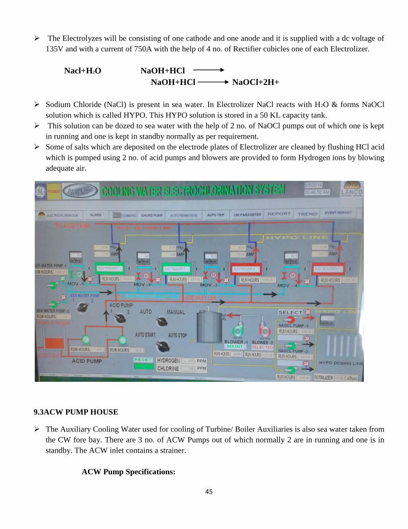
The Electrolyzes will be consisting of one cathode and one anode and it is supplied with a dc voltage of
135V and with a current of 750A with the help of 4 no. of Rectifier cubicles one of each Electrolizer.
Nacl+H2O NaOH+HCl
NaOH+HCl NaOCl+2H+
Sodium Chloride (NaCl) is present in sea water. In Electrolizer NaCl reacts with H2O & forms NaOCl
solution which is called HYPO. This HYPO solution is stored in a 50 KL capacity tank.
This solution can be dozed to sea water with the help of 2 no. of NaOCl pumps out of which one is kept
in running and one is kept in standby normally as per requirement.
Some of salts which are deposited on the electrode plates of Electrolizer are cleaned by flushing HCl acid
which is pumped using 2 no. of acid pumps and blowers are provided to form Hydrogen ions by blowing
adequate air.
9.3ACW PUMP HOUSE
The Auxiliary Cooling Water used for cooling of Turbine/ Boiler Auxiliaries is also sea water taken from
the CW fore bay. There are 3 no. of ACW Pumps out of which normally 2 are in running and one is in
standby. The ACW inlet contains a strainer.
ACW Pump Specifications:
46
Power - 449.4KW
Voltage - 6.6KV
Speed - 1490 rpm
TDH - 52.4mm
No. of stages - 1
Balancing sump depth - 3.7 mtrs
GUARD POND:
The waste water or return water from DM plant, BOP, Boiler, CW sump are collected here and this water
should be sent to disposal, into sea. For this, there are 5no’s of pumps out of which 2 are running normally
and 3 no’s of pumps are standby.
Guard pond Pump specifications: Motor details:
Make: Flow more limited Make: Marathon Electric
Pump input: 138.6KW Voltage: 415V, 50HZ
TDH: 21Mtr Capacity: 180 KW
Speed: 1485RPM Amps: 305A, RPM: 1485, PF: 0.86
Capacity: 2000m3/hr Efficiency: 95%
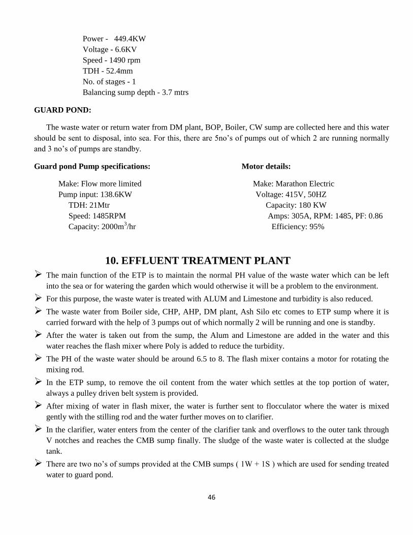
10. EFFLUENT TREATMENT PLANT
The main function of the ETP is to maintain the normal PH value of the waste water which can be left
into the sea or for watering the garden which would otherwise it will be a problem to the environment.
For this purpose, the waste water is treated with ALUM and Limestone and turbidity is also reduced.
The waste water from Boiler side, CHP, AHP, DM plant, Ash Silo etc comes to ETP sump where it is
carried forward with the help of 3 pumps out of which normally 2 will be running and one is standby.
After the water is taken out from the sump, the Alum and Limestone are added in the water and this
water reaches the flash mixer where Poly is added to reduce the turbidity.
The PH of the waste water should be around 6.5 to 8. The flash mixer contains a motor for rotating the
mixing rod.
In the ETP sump, to remove the oil content from the water which settles at the top portion of water,
always a pulley driven belt system is provided.
After mixing of water in flash mixer, the water is further sent to flocculator where the water is mixed
gently with the stilling rod and the water further moves on to clarifier.
In the clarifier, water enters from the center of the clarifier tank and overflows to the outer tank through
V notches and reaches the CMB sump finally. The sludge of the waste water is collected at the sludge
tank.
There are two no’s of sumps provided at the CMB sumps ( 1W + 1S ) which are used for sending treated
water to guard pond.
47
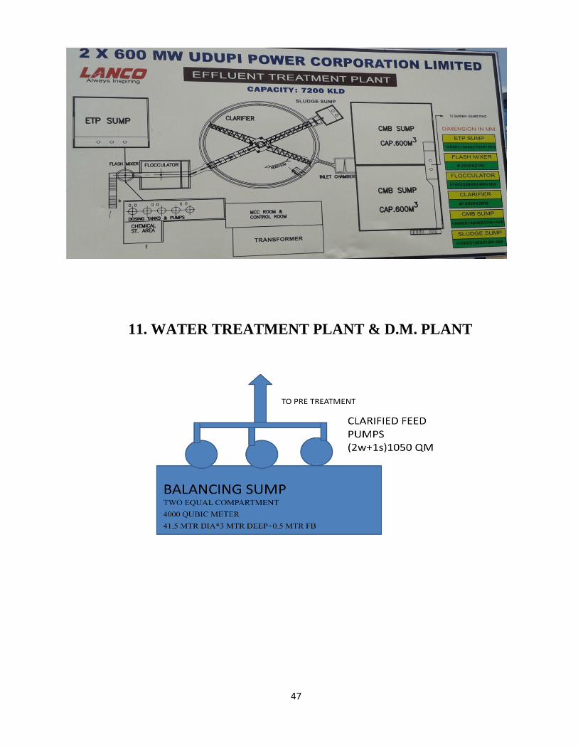
11. WATER TREATMENT PLANT & D.M. PLANT

48
Cascade Aerator:
Water from the sea water balancing sump is pumped to Cascade Aerator with the help of 3 no. of
Clarifier feed pumps out of which one is working and the other is in standby. In cascade aerator sea
water is exposed to oxygen and ultraviolet radiation of sun in order to improve taste and odor.
NaOCl is added to the sea water in cascade aerator for chlorination purpose to reduce algae formation.
The chlorinated water moves forward to the stilling chamber.
Flow rate, maximum of cascade aerator is 2400 m3/hour and Number of steps in cascade aerator are 8.
Stilling Chamber:
The velocity of the water is reduced in the stilling chamber so that we can maintain stable water flow.
FeCl3 & PolyElectrolyte to be added in the path of stilling chamber and flash mixer.
FeCl3 is used to gather all small particles in water. Poly Electrolyte is used to gather all suspended
particles present in the water. The capacity of stilling chamber is 20m3.
Flash Mixer:
Alum and Lime solution is dozed for coagulation through dosing pump. 1 no. of agitator is provided for
proper mixing. The capacity of Flash mixer is 40 m3.
Clariflocculator:
2 no. of Clarriflocculator of circular type are provided with rotating bridge and suspended scrapper.
Clariflocculator is a combination of flocculation and clarification in a single tank.
It has 2 concentric tanks where the inner tank act as a flocculator and outer tank act as a clarifier.
49
In the clariflucculator, the water enters the flocculator where the rotating bridge improves the
flocculation of the solids.
As heavy particles settle at the bottom, the liquid flows upwards in the clarifier zone. The clarifier
discharges water over a peripheral weir into the peripheral launder.
The deposited sludge is settled at the bottom from where it is routed to the sludge sump and discharged to
the sludge tank. Thus general service water is produced for drinking and other domestic purposes.
The normal feed flow through the Clariflocculator is 1050 m3/hr and maximum feed flow is 1200m
3/hr.
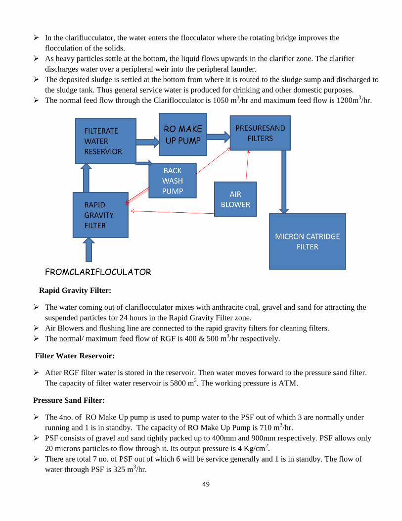
Rapid Gravity Filter:
The water coming out of clariflocculator mixes with anthracite coal, gravel and sand for attracting the
suspended particles for 24 hours in the Rapid Gravity Filter zone.
Air Blowers and flushing line are connected to the rapid gravity filters for cleaning filters.
The normal/ maximum feed flow of RGF is 400 & 500 m3/hr respectively.
Filter Water Reservoir:
After RGF filter water is stored in the reservoir. Then water moves forward to the pressure sand filter.
The capacity of filter water reservoir is 5800 m3. The working pressure is ATM.
Pressure Sand Filter:
The 4no. of RO Make Up pump is used to pump water to the PSF out of which 3 are normally under
running and 1 is in standby. The capacity of RO Make Up Pump is 710 m3/hr.
PSF consists of gravel and sand tightly packed up to 400mm and 900mm respectively. PSF allows only
20 microns particles to flow through it. Its output pressure is 4 Kg/cm2.
There are total 7 no. of PSF out of which 6 will be service generally and 1 is in standby. The flow of
water through PSF is 325 m3/hr.
50
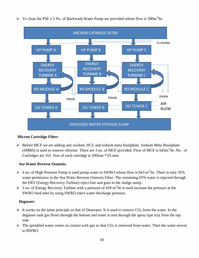
To clean the PSF a 3 No. of Backwash Water Pump are provided whose flow is 580m3/hr.
Micron Cartridge Filter:
Before MCF we are adding anti oxidant, HCL and sodium meta bisulphate. Sodium Meta Bisulphate
(SMBS) is used to remove chlorine. There are 3 no. of MCF provided. Flow of MCF is 643m3/hr. No. of
Cartridges are 161. Size of each cartridge is 100mm * 65 mm.
Sea Water Reverse Osmosis:
4 no. of High Pressure Pump is used pump water to SWRO whose flow is 643 m3/hr. There is only 35%
water permissive in the Sea Water Reverse Osmosis Filter. The remaining 65% water is rejected through
the ERT (Energy Recovery Turbine) reject line and goes to the sludge sump.
3 no. of Energy Recovery Turbine with a pressure of 418 m3/hr is used increase the pressure at the
SWRO feed inlet by using SWRO reject water discharge pressure.
Degasser:
It works on the same principle as that of Deaerator. It is used to remove CO2 from the water. In the
degasser tank gas flows through the bottom and water is sent through the spray type tray from the top
side.
The sprinkled water comes in contact with gas so that CO2 is removed from water. Then the water moves
to BWRO.
51
Back Water Reverse Osmosis:
There is only 20% water permissive in Back Water Reverse Osmosis Filter. The remaining 80% of
water is sent back to the reject line to sludge sump.
The permitted water moves to mixed bed Filter.
Mixed Bed Filter:
Mixed bed filter contains cation and anion resins for removing cations and anions from the water.
For the continuous activation of resins we are adding HCL for cations and NaOH for anions.
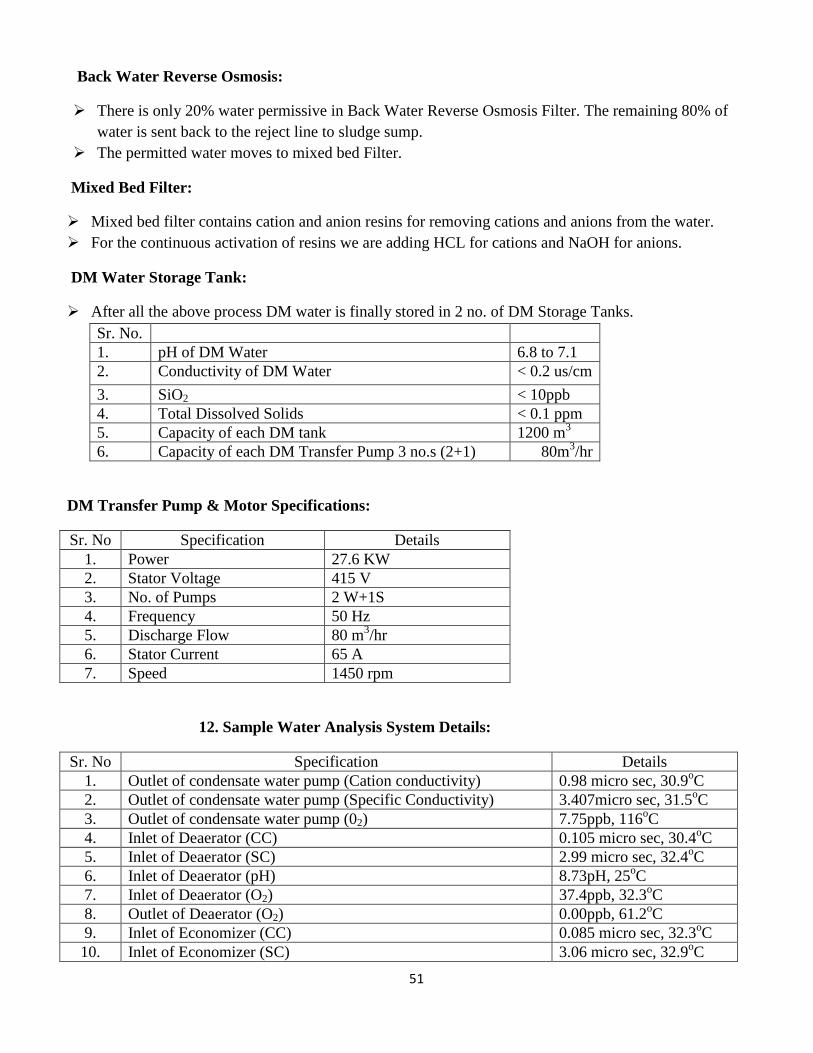
DM Water Storage Tank:
After all the above process DM water is finally stored in 2 no. of DM Storage Tanks.
Sr. No.
1. pH of DM Water 6.8 to 7.1
2. Conductivity of DM Water < 0.2 us/cm
3. SiO2 < 10ppb
4. Total Dissolved Solids < 0.1 ppm
5. Capacity of each DM tank 1200 m3
6. Capacity of each DM Transfer Pump 3 no.s (2+1) 80m3/hr
DM Transfer Pump & Motor Specifications:
Sr. No Specification Details
1. Power 27.6 KW
2. Stator Voltage 415 V
3. No. of Pumps 2 W+1S
4. Frequency 50 Hz
5. Discharge Flow 80 m3/hr
6. Stator Current 65 A
7. Speed 1450 rpm
12. Sample Water Analysis System Details:
Sr. No Specification Details
1. Outlet of condensate water pump (Cation conductivity) 0.98 micro sec, 30.9oC
2. Outlet of condensate water pump (Specific Conductivity) 3.407micro sec, 31.5oC
3. Outlet of condensate water pump (02) 7.75ppb, 116oC
4. Inlet of Deaerator (CC) 0.105 micro sec, 30.4oC
5. Inlet of Deaerator (SC) 2.99 micro sec, 32.4oC
6. Inlet of Deaerator (pH) 8.73pH, 25oC
7. Inlet of Deaerator (O2) 37.4ppb, 32.3oC
8. Outlet of Deaerator (O2) 0.00ppb, 61.2oC
9. Inlet of Economizer (CC) 0.085 micro sec, 32.3oC
10. Inlet of Economizer (SC) 3.06 micro sec, 32.9oC
52
11. Inlet of Economizer (pH) 8.84pH, 32.1oC
12. Inlet of Economizer (O2) 1.17ppb, 32.2oC
13. Boiler water left & right (pH) 9.38pH, 33.9oC
14. Boiler water left & right (SC) 12.4 micro sec, 34.9oC
15. Saturated steam left & right (SC) 4.57micro sec, 32.6oC
16. Saturated steam left & right (CC) 0.127 micro sec, 32.4oC
17. Saturated steam pH left & right 7.85pH, 25oC
18. Superheated steam left & right (CC) 0.145 micro sec, 29.8oC
19. Reheated steam left & right (CC) 0.097micro sec, 29.9oC
20. Sealing cooling water (SC) 19.1 micro sec, 29.3oC
21. Sealing Cooling water (pH) 9.07pH, 27OC
22. Boiler drum PO4 0.07ppm, 0.00ppm
23. CEP Sodium 10.13PH, 0.57 ppb
24. SS Sodium 2.1ppb, 10.4 pH
25. Feed water Silica 0.0ppb
26. Main Steam silica 0.0 ppb
27. Boiler left & right silica 33.1 ppb, 0.0ppb
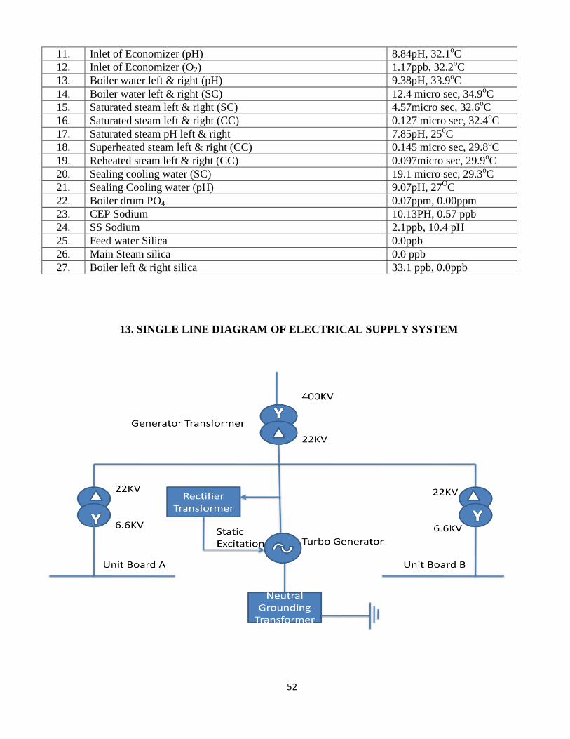
13. SINGLE LINE DIAGRAM OF ELECTRICAL SUPPLY SYSTEM
53
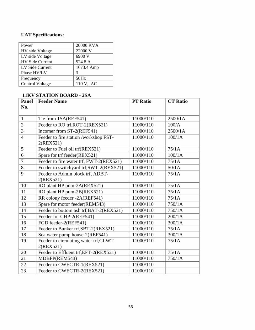
UAT Specifications:
Power 20000 KVA
HV side Voltage 22000 V
LV side Voltage 6900 V
HV Side Current 524.8 A
LV Side Current 1673.4 Amp
Phase HV/LV 3
Frequency 50Hz
Control Voltage 110 V, AC
11KV STATION BOARD - 2SA
Panel
No.
Feeder Name PT Ratio CT Ratio
1 Tie from 1SA(REF541) 11000/110 2500/1A
2 Feeder to RO trf,ROT-2(REX521) 11000/110 100/A
3 Incomer from ST-2(REF541) 11000/110 2500/1A
4 Feeder to fire station /workshop FST-
2(REX521)
11000/110 100/1A
5 Feeder to Fuel oil trf(REX521) 11000/110 75/1A
6 Spare for trf feeder(REX521) 11000/110 100/1A
7 Feeder to fire water trf, FWT-2(REX521) 11000/110 75/1A
8 Feeder to switchyard trf,SWT-2(REX521) 11000/110 50/1A
9 Feeder to Admin block trf, ADBT-
2(REX521)
11000/110 75/1A
10 RO plant HP pum-2A(REX521) 11000/110 75/1A
11 RO plant HP pum-2B(REX521) 11000/110 75/1A
12 RR colony feeder -2A(REF541) 11000/110 75/1A
13 Spare for motor feeder(REM543) 11000/110 750/1A
14 Feeder to bottom ash trf,BAT-2(REX521) 11000/110 750/1A
15 Feeder for CHP-2(REF541) 11000/110 200/1A
16 FGD feeder-2(REF541) 11000/110 300/1A
17 Feeder to Bunker trf,SBT-2(REX521) 11000/110 75/1A
18 Sea water pump house-2(REF541) 11000/110 300/1A
19 Feeder to circulating water trf,CLWT-
2(REX521)
11000/110 75/1A
20 Feeder to Effluent trf,EFT-2(REX521) 11000/110 75/1A
21 MDBFP(REM543) 11000/110 750/1A
22 Feeder to CWECTR-1(REX521) 11000/110
23 Feeder to CWECTR-2(REX521) 11000/110
54
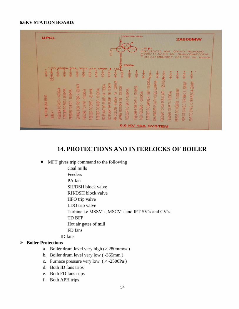
6.6KV STATION BOARD:
14. PROTECTIONS AND INTERLOCKS OF BOILER
MFT gives trip command to the following Coal mills
Feeders
PA fan
SH/DSH block valve
RH/DSH block valve
HFO trip valve
LDO trip valve
Turbine i.e MSSV’s, MSCV’s and IPT SV’s and CV’s
TD BFP
Hot air gates of mill
FD fans
ID fans
Boiler Protections
a. Boiler drum level very high (> 280mmwc)
b. Boiler drum level very low ( -365mm )
c. Furnace pressure very low ( < -2500Pa )
d. Both ID fans trips
e. Both FD fans trips
f. Both APH trips
55
g. Scanner cooling air pressure very low (<3KPa )
h. 220V dc supply fail in MFT ( Triconex )
i. Furnace flame off
j. Air flow < 30%
k. RH Protection ( when fuel flow < 78 T/hr )
l. Both PA fans trips/stopped when any mill is running and no oil gun is in service
m. Turbine trip to boiler trip when load is < 40%
n. All BFP’s Trip
o. Operator’s choice ( MFT )
p. Triconex 230V AC power supply fail power monitoring relay
LDO Protections:
a. Light oil pressure very low
b. Atomizing air pressure very low
c. MFT to LOFT
d. Operator’s choice LOFT
e. At least one oil gun must in service for light oil pressure very low
f. For Light oil trip valve to open. No MFT should persist. All nozzle valves to be closed. Oil
leak test to be completed or leak test to be by passed and LDO pressure adequate before trip
valve.
HFO Protections:
a. Heavy oil pressure very low
b. Atomizing steam pressure very low
c. Heavy oil temperatures very low
d. MFT to HOFT
e. Operator’s choice MFT
f. At least one oil gun must be in service for HO pressure very low and atomizing steam pressure very
low and oil temp low protection to act.
g. For heavy oil trip valve to open NO MFT should persist, all nozzle valves must be closed. Oil lead
test to be completed or leak test to be by passed and heavy oil pressure adequate before the trip
valve.
15. PROTECTIONS AND INTERLOCKS OF TURBINE
a. Over speed
b. Axial movement
c. Lub oil pressure low 0.07 MPa
d. EH oil pressure low 7.8 MPa
e. LPT exhaust temperature high 1070c
f. Low vacuum trip -74.5KPa
g. Thrust pad metal temp 1100c
h. DEH failure trip
i. HP bypass fail (only applicable in HP start up mode)
56
j. LP bypass fail (HP bypass CV in closed condition and LP bypass CV command >30%)
k. Main inlet temp low (Alarm 4740c, Trip 460
0c when load>50%)
l. MFT trip
m. Generator failure trip
n. HP exhaust metal high temperature trip 4200c
o. Generator cooling water low
p. Turbine shaft vibration high trip (alarm 120 microns & trip 250 microns)
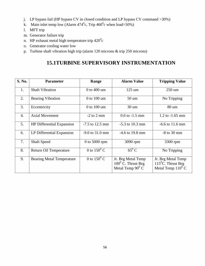
15.1TURBINE SUPERVISORY INSTRUMENTATION
S. No. Parameter Range Alarm Value Tripping Value
1. Shaft Vibration 0 to 400 um 125 um 250 um
2. Bearing Vibration 0 to 100 um 50 um No Tripping
3. Eccentricity 0 to 100 um 30 um 80 um
4. Axial Movement -2 to 2 mm 0.6 to -1.5 mm 1.2 to -1.65 mm
5. HP Differential Expansion -7.5 to 12.5 mm -5.3 to 10.3 mm -6.6 to 11.6 mm
6. LP Differential Expansion -9.0 to 31.0 mm -4.6 to 19.8 mm -8 to 30 mm
7. Shaft Speed 0 to 5000 rpm 3090 rpm 3300 rpm
8. Return Oil Temperature 0 to 1500 C 65
0 C No Tripping
9. Bearing Metal Temperature 0 to 1500 C Jr. Brg Metal Temp
1000 C. Thrust Brg
Metal Temp 900 C
Jr. Brg Metal Temp
1150C. Thrust Brg
Metal Temp 1100 C
57
CONCLUSION:
As per the time limit considerations this book has covered the almost all critical aspects of Thermal Power
Plant starting from Coal Handling to importing and exporting of power generated in the power plant. This
book mainly focuses on Operations and Maintenance aspects of a Thermal Power Plant and important
systems are line traced.
BIBLIOGRAPHY
1) UPCL Technical Dairy
2) UPCL P & ID’s
3) UPCL Engineer’s Manual