study of helicopter performance and terminal instrument ... · pdf filestudy of helicopter...
TRANSCRIPT
Report No. FAA-RD-80-58
STUDY OF HELICOPTER PERFORMANCEAND
TERMINAL INSTRUMENT PROCEDURES, A.G. DeLucien
D.L. GreenO H.R. Pricelet F.D. Smith
PACER Systems, Inc.1755 S. Jefferson Davis Highway
Arlington, Virginia 22202
011k
June 1980
FINAL REPORT
Document is available to the U.S. public throughthe National Technical Information Service,
Springfield, Virginia 22161.
Prepared for
U.S. DEPARTMENT OF TRANSPORTATION0: FEDERAL AVIATION ADMINISTRATION
Systems Research & Development ServiceWashington, D.C. 20590
o, , m. .,
NOTICE
This document is disseminated under the sponsorship of the Department of
Transportation in the interest of information exchange. The United States
Government assumes no liability for the contents or use thereof.
Techaical bpmt Decinties Pep
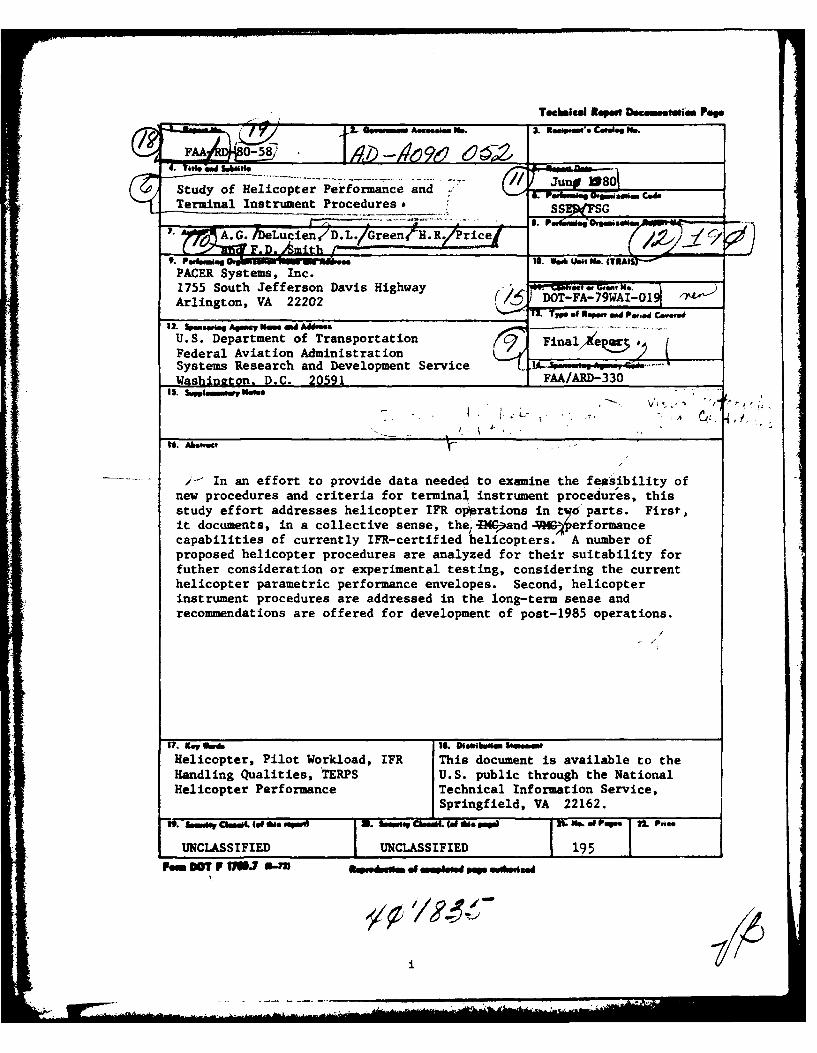
FAA 0- 5 8
Study of Helicopter Performance and G.-%*40jo,"s OTerminal Instrument Proceduress,
7 A.G. /DLucien /D.L./ee : 7Q e
9. - .iga 10. %A~ Unit Pl.. (TRA16lSPACER Systems, Inc.1755 South Jefferson Davis HighwayArlington, VA 22202 ( DOT-FA-79WAI-1-
___ ___ ___ ___ ___ ___ ___ ___ ___ ___ 73 . .M f ipwt OW P...dC....d
12. $b-s..'. Agan.em. AMW .U.S. Department of Transportation Fna,~aFederal Aviation Administration ______________________
Systems Research and Development Service $. ______1_
Washinaton. D.C. 20591 FMA/ARD-330
It. Abe...
i- In an effort to provide data needed to examine the feasibility ofnew procedures and criteria for terminal instrument procedures, thisstudy effort addresses helicopter IFR oiprations in t qo parts. First-,it documents, in a collective sense, the 4Mand HG erformancecapabilities of currently IFR-certified helicopters. A number ofproposed helicopter procedures are analyzed for their suitability forfuther consideration or experimental testing, considering the currenthelicopter parametric performance envelopes. Second, helicopterinstrument procedures are addressed in the long-term sense andrecommendations are offered for development of post-1985 operations.
Helicopter, Pilot Workload, IFR This document is available to theHandling Qualities, TERPS U.S. public through the NationalHelicopter Performance Technical Information Service,
Springfield, VA 22162.
ff. Mmw mI.IEd.. Swimk CE=L.0 A.E peI 2n. N*.of Form 22. Pri..
UNCLASSIFIED UNCLASSIFIED 195Pm OW P USJ S-fl in-Awli.e of =G~.. pep mG d
il"
:10
d c; -
I To
10 16 T II 1c Ta
6 .3 3 ~ m .1
asI
N a ;0 a
tz~~~~ igt£~ ta
PREFACE
The study described in this report was sponsored by the Helicopter
Systems Branch of the Systems Research and Development Service, Federal
Aviation Administration, U.S. Department of Transportation, under Contract
No. DOT-FA-79WA1-019. Mr Glen D. Adams (ARD-330) served as technical
monitor and engineer for SRDS. The authors wish to express their apprecia-
tion to the branches and sections of the FAA; namely, the Office of Flight
Operations (AFO-203), and the Flight Standards National Field Office
(AFO-560 and AFO-507) at Oklahoma City, for their cooperation in this
research effort.
Additionally, the authors wish to extend heartfelt appreciation to
Mrs. Adahmarie Hyatt, Ms. Anne Smoot and Ms. Ginny Herensperger for the
long hours of typing and retyping of this report; also to Ms. Herensperger
for her efforts in generating most of the graphics.
Accesson For--
DTIC T's
DiTst '-
ft-ii, i

TABLE OF CONTENTS
Section Page
1 INTRODUCTION . .. .. .. .. .. .. .. .. . .. 1- 1
2 HELICOPTER PERFORMANCE .. .. .. .. .. .. . .. 2- 1
INTRODUCTION ....... .................. ... 2- 1
GENERALIZATIONS ON CHARACTERISTICS OF IFRCAPABLE HELICOPTERS. . ............ 2- 2
Data Sources . . ........ . . . . .. . 2- 2
Overview of Certification Limits ......... . 2- 2
Aspects of Performance Considered. . . . . . . 2- 4
DISCUSSION OF HELICOPTER CAPABILITIES INRELATION TO CURRENT CERTIFICATIONREQUIREMENTS ...... ................. ... 2- 6
Arrival Phase ...... ................. ... 2-10
Practical Limits On Rate Of Descent. . . . . 2-10
Visual Approach Segment Profiles . . . . . . 2-11
Advantages Of Steeper Precision Approaches . 2-17
Parametric Analysis Of HelicopterApproach Performance .... ............ . 2-19
Recommended Extensions To HelicopterTERPS Approach Criteria ................ 2-25
Departure/Missed Approach Phase 2-26
SUMMARY OF HELICOPTER PERFORMANCE ........... 2-33
3 FUTURE DEVELOPMENTS ..... ................ ... 3- 1
INTRODUCTION ....... .................... 3- 1
HANDLING QUALITIES IN SLOW FLIGHT ... .. . . 3- 2
Instrumentation and Cues ... .......... . 3- 2
Slow Flight Performance. . . . . . .. 3- 3
Control Augmentation ... . . . . . . . . 3- 4
iv
TABLE OF CONTENTS
Section Page
Army Experience ...... ................ ... 3- 5
APPROACH PROFILES IN SLOW FLIGHT .......... . 3- 6
Height-Speed Envelope ........ . .... . . 3- 6
Approach Corridor Considerations .......... 3- 8
Very Steep, Constant Speed Approaches . .... 3- 9
APPENDIX A INDIVIDUAL HELICOPTER PERFORMANCESUMMARIES .. . ................ A- i
REFERENCES .......... .......................... . R- 1
V
-k,- " : ... .. .. . i . . . -. .
LIST OF ILLUSTRATIONS
Figure Page
2- 1 Overview of Bounds on HelicopterIFR Flight Envelope ..... ............... ... 2- 3
2- 2 Envelope of Autorotation Characteristics . . . . 2- 5
2- 3 Variation of Rate of Climb with GroundspeedNecessary to Maintain a 1:20 Climb Gradient. • 2- 7
2- 4 Variation of Rate of Climb with GroundspeedNecessary to Maintain a 1:40 Climb Gradient. * 2- 7
2- 5 Example Carpet Plot of ClimbPerformance Capability for aRepresentative Modern Helicopter ......... ... 2- 8
2- 6 Variation of Rate of Descent with Aircraft
Speed and Descent Angle or Slope ......... ... 2-12
2- 7 Average VFR Altitude Profiles ............. ... 2-14
2- 8 Average Ground-Speed Profiles ............. ... 2-15
2- 9 Computer-Generated Deceleration Profiles for
Different Airspeed and Altitude Conditions . • 2-16
2-10 Correspondence of Altitude with Rangefor Various Descent Angles ... .......... . 2-18
2-11 Variation of Rate of Descent withVarious Approach Speeds and Descent Angles . . 2-20
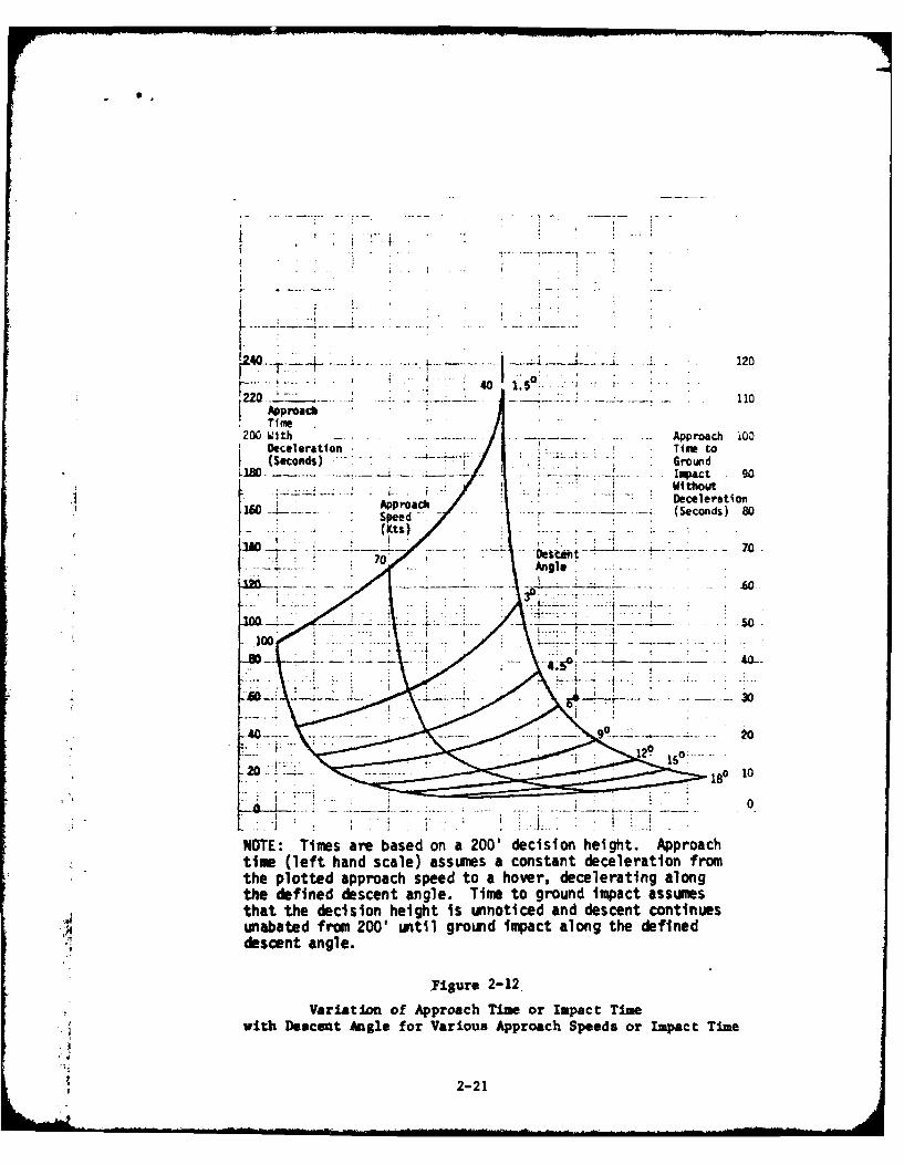
2-12 Variation of Approach Time or Impact Timewith Descent Angle for Various ApproachSpeeds or Impact Time ....... .......... 2-21
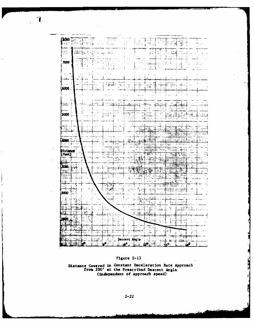
2-13 Distance Covered in Constant DecelerationRate Approach from 200' at thePrescribed Descent Angle ... ........... ... 2-22
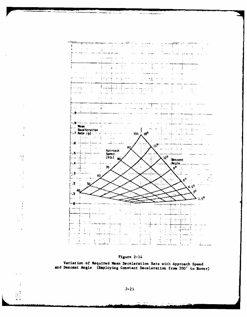
2-14 Variation of Required Mean DecelerationRate with Approach Speed and DescentAngle (Employing Constant Decelerationfrom 200' to Hover) ..... .............. .... 2-23
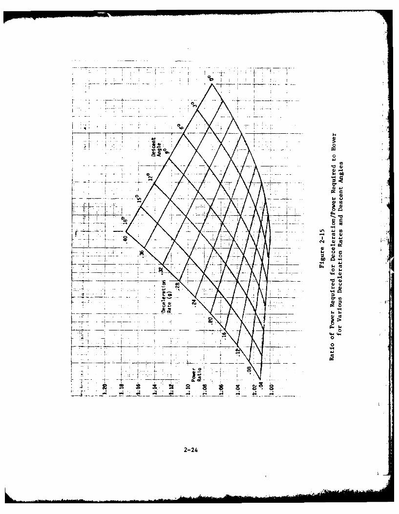
2-15 Ratio of Power Required for Deceleration/Power Required to Hover for VariousDeceleration Rates and Descent Angles ..... 2-24
vi
LIST OF ILLUSTRATIONS
FPage
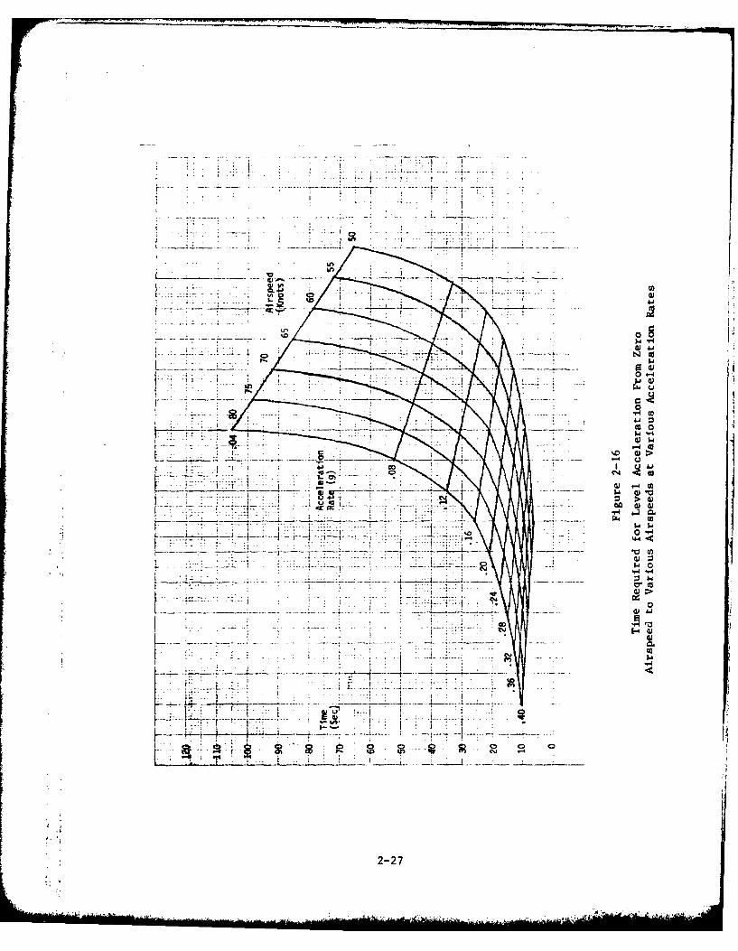
2-16 Time Required for Level Acceleration FromZero Airspeed to Various Airspeeds atVarious Acceleration Rates ... .......... . 2-27
2-17 Distance Required for Level Acceleration FromZero Airspeed to Various Airspeeds at VariousAcceleration Rates .................. 2-28
2-18 Variation of Rate of Climb with Airspeed . . . . 2-32
3- 1 Composite Height - Speed Diagramfor Single-Engine IFR Certificated Helicopters 3- 7
3- 2 Composite Height - Speed Diagramfor Multi-Engine IFR Certificated Helicopters. 3- 7
3- 3 Variation of Ground Speed with Rate ofDescent and Descent Angle for Steep Descents . 3-11
vii
LIST OF ABBREVIATIONS
AC Advisory Circular
ASW Antisubmarine Warfare
DH Decision Height
DME Distance Measuring Equipment
DOD Department of Defense
FAA Federal Aviation Administration
HIGE Hover In Ground Effect
HOGE Hover Out of Ground Effect
H-V Height-Speed (Height-Velocity)
IFR Instrument Flight Rules
ILS Instrument Landing System
IMC Instrument Meteorological Conditions
MLS Microwave Landing System
NAS National Airspace System
NASA National Aeronautics and Space Administration
ROC Rate of Climb
ROD Rate of Descent
RVR Runway Visual Range
SRDS Systems Research and Development Service
TERPS Terminal Instrument Procedures
TCA Terminal Control Area
TN Technical Note
viii
LIST OF ABBREVIATIONS
USCG United States Coast Guard
VMC Visual Meteorological Conditions
V/STOL Vertical/Short Takeoff and Landing
LIST OF SYMBOLS
V Velocity.
V Velocity never exceed.ne
V Velocity, vertical, knots or feet/minutev
VTOSS Takeoff safety speed
y Flight path angle, degrees
9 Acceleration due to gravity (32.2 ft/sec )
ix/x
SECTION 1
INTRODUCTION
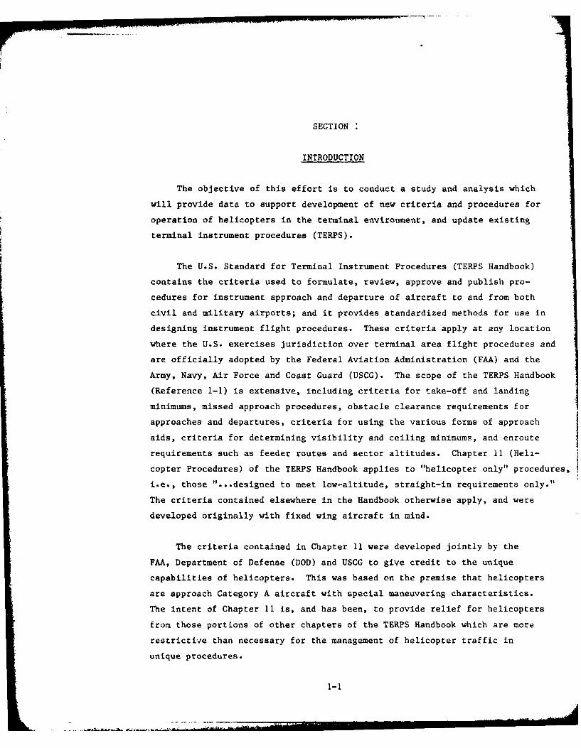
The objective of this effort is to conduct a study and analysis which
will provide data to support development of new criteria and procedures for
operation of helicopters in the terminal environment, and update existing
terminal instrument procedures (TERPS).
The U.S. Standard for Terminal Instrument Procedures (TERPS Handbook)
contains the criteria used to formulate, review, approve and publish pro-
cedures for instrument approach and departure of aircraft to and from both
civil and military airports; and it provides standardized methods for use in
designing instrument flight procedures. These criteria apply at any location
where the U.S. exercises jurisdiction over terminal area flight procedures and
are officially adopted by the Federal Aviation Administration (FAA) and the
Army, Navy, Air Force and Coast Guard (USCG). The scope of the TERPS Handbook
(Reference 1-1) is extensive, including criteria for take-off and landing
minimums, missed approach procedures, obstacle clearance requirements for
approaches and departures, criteria for using the various forms of approach
aids, criteria for determining visibility and ceiling minimums, and enroute
requirements such as feeder routes and sector altitudes. Chapter 11 (Hell-
copter Procedures) of the TERPS Handbook applies to "helicopter only" procedures,
i.e., those "...designed to meet low-altitude, straight-in requirements only."
The criteria contained elsewhere in the Handbook otherwise apply, and were
developed originally with fixed wing aircraft in mind.
The criteria contained in Chapter 11 were developed jointly by the
FAA, Department of Defense (DOD) and USCG to give credit to the unique
capabilities of helicopters. This was based on the premise that helicopters
are approach Category A aircraft with special maneuvering characteristics.
The intent of Chapter 11 is, and has been, to provide relief for helicopters
from those portions of other chapters of the TERPS Handbook which are more
restrictive than necessary for the management of helicopter traffic in
unique procedures.
1-1
When Chapter 11 was first issued in 1970, numerous military helicop-
ters were operating under instrument meteorological conditions, but only
two civil helicopter models were certified for flight under Instrument Flight
Rules (IFR). Because the vast majority of IFR-capable helicopters were in
the military, much of the data used in developing Chapter 11 were derived
from flight tests with military equipment. At present, more than 11 civil
helicopter models are IFR-certified, others are undergoing the certifi-
cation process, and most future helicopters are expected to be offered by
manufacturers IFR-certified "off-the-shelf". This has been the result of
operator demand and some industry estimates suggest that the number of IFR
capable helicopters operating in the United States may number well into the
thousands in the 1980s.
As the state-of-the-art of the helicopter industry improves, the FAA
continues to revise TERPS to permit greater latitude in helicopter IFR
operations. Industry requests for additional freedom have been based upon
assertions of unique capabilities of helicopters. Such requests typically
include: reduced landing and takeoff minimums, less restrictive alternate
minimums, steeper approach angles, revised obstruction clearance gradients,
relaxed weather reporting criteria, and more.
When addressing the operation of helicopters under instrument meteor-
ological conditions (IMC) within the national airspace system (NAS), there
is one particular segment of that airspace system that is readily identi-
fied as being critical, with significant impact on operational profiles:
the terminal environment. That terminal environment typically is a highly
structured airspace that ranges from high-density Terminal Control Areas
(TCAs) to light and medium-density airport traffic areas. As the heli-
copter becomes more and more integrated into the IFR operational environ-
ment, terminal operations foreseeably may include a number of remote
traffic areas suitable only for helicopter use.
1-2
In an effort to provide the data needed to examine the feasibility of
new procedures and criteria for helicopter terminal instrument procedures,
this study effort addresses helicopter IFR operations in two parts. First, it
documents, in a collective sense, the IMC and visual meteorological condi-
tions (VMC) performance capabilities of currently IFR-certified helicopters.
Second, it addresses helicopter instrument procedures in the long-term sense
(future TERPS) and offers recommendations for post - 1985 operations.
1-3/4
SECTION 2
HELICOPTER PERFORMANCE
INTRODUCTION
This section addresses capabilities of helicopters as they bear upon
the problems of managing IFR operations in approach, missed approach and
departure at sites uniquely suited for helicopters or other forms of
Vertical/Short Takeoff and Landing (V/STOL) aircraft. The discussion
centers on limiting aspects of helicopter performance capabilities to
ensure that criteria for IFR terminal procedures intended for "Copter Only"
utilization may be considered within the envelope of physical capability
rather than scoped entirely by experience evolved from operations with
fixed wing aircraft.
The discussion of helicopter capabilities addresses performance of
helicopters as defined by current certification standards, the most signif-
icant aspect of which is the definition of a minimum IFR airspeed for
each certificated helicopter. Consequently, the discussion focuses on
Category I and II approaches in which the airspeed is stable upon reaching
decision height and minimal changes are necessary to effect a missed
approach. Corollary issues concern the IMC procedural interfaces with the
visual decelerating segment to the landing spot and the visual acceleration
segment during departure.
As an introduction to the discussion, characteristics of currently
active IFR capable helicopters have been reviewed. Data, principally
obtained from their respective flight manuals, have been summarized for
each of eleven different helicopters, mostly civil, with certification for
IMC operations in the U.S. plus a few military helicopters to complete the
spectrum of size and configuration. Individual summaries are presented in
Appendix A.
2-1
GENERALIZATIONS ON CHARACTERISTICS OF IFR CAPABLE HELICOPTERS
Data Sources
The summaries of performance data contained in Appendix A are limited
in scope to those data of nearly universal availability in FAA approved (or
analogous military) flight manuals. Generally speaking, these manuals
reveal information concerning limitations on capability specified in the
Type Certificate or IFR Supplementary Type Certificate and a modest scope
of performance characteristics in climb, hover, and cruising flight. Some
information concerning autorotation characteristics is provided, but
several manufacturers had to be directly consulted to obtain rates-of-
descent associated with their recommended airspeeds. Military manuals were
much more comprehensive, but neither military nor civil manuals provided
direct data or discussion of handling characteristics. It may only be
inferred from these manuals that handling qualities are acceptable within
the limitations imposed. but there is no assurance that handling qualities
meet current criteria beyond those limitations. In particular, it may be
assumed that the minimum IFR airspeed of a civil helicopter represents a
boundary below which criteria regarding control force or position stability
characteristics cannot be satisfied. Military aircraft do not universally
impose a minimum IFR airspeed; however, most military flight manuals
reviewed did suggest that airspeeds below 40-50 knots be avoided during IMC
operations due tc the unreliability of pitot-static instrumentation in that
flight regime. Civil regulations do not establish performance requirements
for airspeed measuring systems which completely cover the low airspeed
spectrum of the helicopter performance envelope.
Overview of Certification Limits
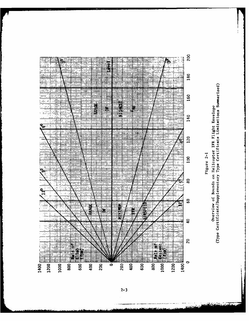
Figure 2-1 provides an overvicw of the boundaries imposed by certi-
fication limits. Minimum IFR airspeeds for level or descending flight
range between 40 and 60. The range of maximum V runs from 130-175 knotsne
for the aircraft summarized in Appendix A. However, V is decreased belowne
this maximum limit for all of these aircraft when altitude is increased and
2-2
C)
~0 0 m
C- Wj.J
77 -U -
ri. .
0)
t co
w u
C).
C>
oD 0D 0D 0 0 D 0 a 0 0 ) a 0 00CD (DJ 0 D CD C Ci CD 90 D 0D CD C)
2-3
and for many when gross weight is increased. This variation can reduce Vne
to the point that some models of helicopter barely satisfy minimum IFR air-
speed requirements while operating at the reduced Vne at maximum authorized
altitudes and/or weights. Additional limitations have been imposed on aircraft
individually regarding maximum rates of climb or descent, steepest approach
angle, or maximum altitude for landing and takeoff. These additional limita-
tions have resulted, in some cases, from the extent to which capabilities have
been demonstrated and, in others, from inherent bounds on capability vis-a-vis
certification requirements. Flight manuals do not identify the rationale for
such limitations, only the performance boundaries.
Aspects of Performance Considered
Three aspects of performance are documented in the data packages of
Appendix A for each IFR capable helicopter. These are autorotation per-
formance, climb performance and hover performance. Autorotation perfor-
mance is discussed in this report to define physical limitations on rate of
descent. Climb performance is documented for best rate-of-climb airspeed
or recommended IFR climb airspeed, when different, using maximum continuous
power. Hover performance significantly influences considerations for possible
employment of decelerating or other innovative approaches to be discussed in
Section 3 and may be employed to advantage in reviewing missed approach
procedures for "Copter Only" within current certification requirements as
well.
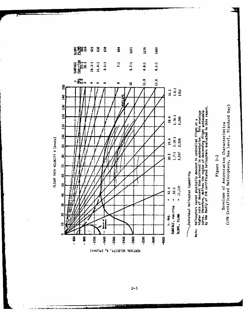
Autorotation performance capabilities are summarized in Figure 2-2.
Where data were available, airspeed and rate-of-descent have been plotted
for each helicopter at the speed for minimum rate-of-descent in autorota-
tion and also at the speed for shallowest glide angle. Collectively, the
individual performance curves have been bounded by an envelope curve in
Figure 2-2. This shows that helicopters, in general, are physically limited
to rates of descent of as little as 1400 fpm at airspeeds between 50-70 knots
and may not be capable of descent angles (under no wind conditions) steeper
than 100 at airspeeds above 100 knots.
2-4
V% qn a. c
000
0~~4 an vC ~2 __2 - -cc
, , I . '0 u
P /W / C .c ,-.01
-A a $
4o 4u v an
-o N
.o c 4
.4, ; Z 0
0 00 -4
.- 41 41
CO~ -
-D LOW*
040
(U W1,4)A A AII313A V3la
-2-5.
The carpet plots of climb performance shown in Appendix A do not provide
such a useful opportunity for generalization regarding capabilities as the
autorotation data do. It can be seen from examining the climb performance
data for any of the helicopters that, for some combinations of gross weight,
temperature and altitude, each helicopter is absolutely unable to climb at
maxlum continuous power. Inasmuch as climb performance of helicopters is not
readily generalized, it is more useful to look at a generalization of the
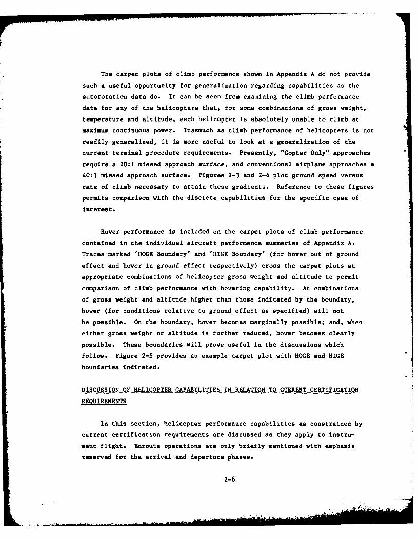
current terminal procedure requirements. Presently, "Copter Only" approaches
require a 20:1 missed approach surface, and conventional airplane approaches a
40:1 missed approach surface. Figures 2-3 and 2-4 plot ground speed versus
rate of climb necessary to attain these gradients. Reference to these figures
permits comparison with the discrete capabilities for the specific case of
interest.
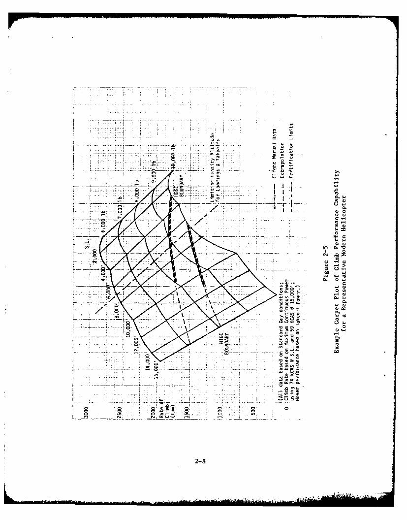
Hover performance is included on the carpet plots of climb performance
contained in the individual aircraft performance summaries of Appendix A.
Traces marked 'HOGE Boundary' and 'HIGE Boundary' (for hover out of ground
effect and hover in ground effect respectively) cross the carpet plots at
appropriate combinations of helicopter gross weight and altitude to permit
comparison of climb performance with hovering capability. At combinations
of gross weight and altitude higher than those indicated by the boundary,
hover (for conditions relative to ground effect as specified) will not
be possible. On the boundary, hover becomes marginally possible; and, when
either gross weight or altitude is further reduced, hover becomes clearly
possible. These boundaries will prove useful in the discussions which
follow. Figure 2-5 provides an example carpet plot with HOGE and HIGE
boundaries indicated.
DISCUSSION OF HELICOPTER CAPABILITIES IN RELATION TO CURRENT CERTIFICATION
REQUIREMENTS
In this section, helicopter performance capabilities as constrained by
current certification requirements are discussed as they apply to instru-
ment flight. Enroute operations are only briefly mentioned with emphasis
reserved for the arrival and departure phases.
2-6
70D
600
note L.
d .4 ...
A-- 166 50 0 40~ 0 go O.1 U0. Ito-. 1)0 -. 40 ISO
_____Gtyund Spqod .(.9noQ 4
Figure 2-3
Variation of Rate of Climb with Groundspeed Necessaryto Mantain a 1:20 Climb Gradient
5W ~ ------ ___
.... D5 0 ... 80 90.-100-1 12-2140 IS0
Si 4 4
Figure 2-4
Varato of Rate of Climb with Groundspeed Necessaryto Maintain a 1:40 Climb Gradient
2-7
-7 7
7~
,0c 0-0
0 . - x G j1
co I . I
- 4~
CDo
7-C>u. a)
Ln
C ~C 3
0T 0 41
3? 42 6 -44
M0 Gj C.
(Aj0.U - 4-
.0 tv
28 z0 )
Certification requirements regularly result in definition of three
limitations which impact enroute performance of helicopters operating IMC.
These are the definition of minimum IFR airspeed--typically ranging from
40-60 knots in level or descending flight; maximum altitude--variously
defined as pressure or density altitude and typically of the order of
15,000-20,000 feet; and V --the maximum values of which range betweenne
130 and 175 knots. These data are summarized in Figure 2-1. Helicopters
may also be limited by handling qualities to maximum rates of descent or
climb in IMC; and, in some cases, higher minimum IFR speeds apply during
climb--ranging up to 70 knots.
Limits shown in Figure 2-1 represent the range of maximum V forne
the aircraft considered. Published V always decreases from the maximumne
as a function of increasing altitude and/or temperature. Many helicopters
also inhibit V for increasing gross weight. Each civil aircraft mustme
display a placard of V variations. At the greatest extremes of densityne
altitude (and sometimes gross weight) V is reduced to airspeeds of thene
order of 70 to 100 knots. (In one case the minimum V is actually lessme
than the corresponding minimum IFR airspeed). Helicopter V is usuallyme
defined by structural or control considerations, such as the approach of
retreating blade stall (determined by blade loading, true airspeed and air
density). The published limits are determined through the certification
process, but they are linked to performance limitations which reflect both
excessive vibration and the onset of controllability problems. Vne when
expressed as calibrated airspeed, is typically constant with increasing
altitude until a critical density altitude is reached at which blade stall
effects require a further limitation in airspeed. Density altitudes at
which this transition occurs are a function of gross weight and reflect the
arbitrary design choices resulting from tradeoffs. Density altitudes of
3000-5000 feet are typically the regime in which blade stall effects begin
to limit Vme' but individual designs or extremes in gross weight may
result in significant deviations. Once blade stall effects are encountered,
V ne must be reduced by approximately 3-8 knots per 1000' of additional
altitude. The rate of reduction again results from design choices peculiar
2-9
to the individual helicopter. In the immediate future, application ofnoise standards may also impact the design choices which influence V
ne
inasmuch as rotor impulsive noise is associated with the high local Mach
numbers near the tip of the advancing blades at the same time that stall
considerations apply to the aerodynamic performance of the retreating
blades. The several phenomena which now, or shortly will, influence Vne
all contribute to a very pragmatic preference among helicopter pilots for
the lowest feasible enroute altitudes.
Arrival Phase
The arrival phase of instrument operations is not, generally, impacted
by additional certification constraints. (An exception; one helicopter is
precluded from precision approaches involving glide paths steeper than
3.50.) However, practical limits on rate of descent must be considered
in evaluating helicopter approach capabilities.
Practical Limits On Rate Of Descent
With the prospective advent of Microwave Landing Systems (MLS) which
will provide precision elevation guidance signals up to 200, much interest
has been shown by the helicopter community in flying steeper precision
approaches than are supportable with present Instrument Landing Systems
(ILS) (slightly more than 3 ). Figure 2-2 shows curves of limiting rate
of descent in autorotation for IFR capable helicopters. An envelope curve
has been inferred and drawn which bounds the autorotation curves of each of
the individual helicopters. Autorotation is a physical limitation on rate
of descent of helicopters, so a buffer descent rate of approximately
400-500 fpm is necessary to define a mean sustainable rate of descent or
descent angle. The buffer is needed because autorotation is a state of
operations in which the rotor system is driven by the descent of the
helicopter rather than power from the engine(s). Rotor speed is no
longer governed by the engine power management system, and controllability
may become marginal. If attempting to track a prescribed glidepath, pilots
2-10
should not be expected to correct from a high, fast error position by
operating near the autorotation boundary. Consequently, 1,000 fpm would
appear to be the reasonable maximum rate of descent which can be practically
achieved in the airspeed regime of 40-70 knots. This figure gradually
increases to 1,500 fpm by 110 knots. These recommendations correspond to
descent angles which range from 140 at the low end of the airspeed
spectrum to 80 at 110 knots. Above 110 knots, at all airspeeds, descent
angles of up to 80 should be sustainable throughout the allowable air-
speed range unless handling qualities should deteriorate at very high
speeds and high rates of descent.
Two factors should be considered in attempting to evaluate the impli-
cations of these limits on descent rate or descent angle. First, steep
descent angles can only be achieved at the low end of the airspeed spectrum
near the minimum IFR airspeed. The influence of wind on flight path is
most severe at the lower speeds since any given amount of wind represents a
higher proportion of the approach speed; and, at minimum IFR airspeed,
the aspects of handling qualities have already been shown to be marginal.
The second factor relates to non-precision approaches. According to
helicopter TERPS, the steepest permissible gradient for such approaches is
800 feet per nautical mile, which corresponds to 7.50 (with no wind).
This already presses the limiting capability of helicopters at the higher
airspeeds which many flight manuals recommend for such approaches, so there
is little opportunity to increase the non-precision approach gradient.
Consequently, instrument approaches steeper than now authorized may only
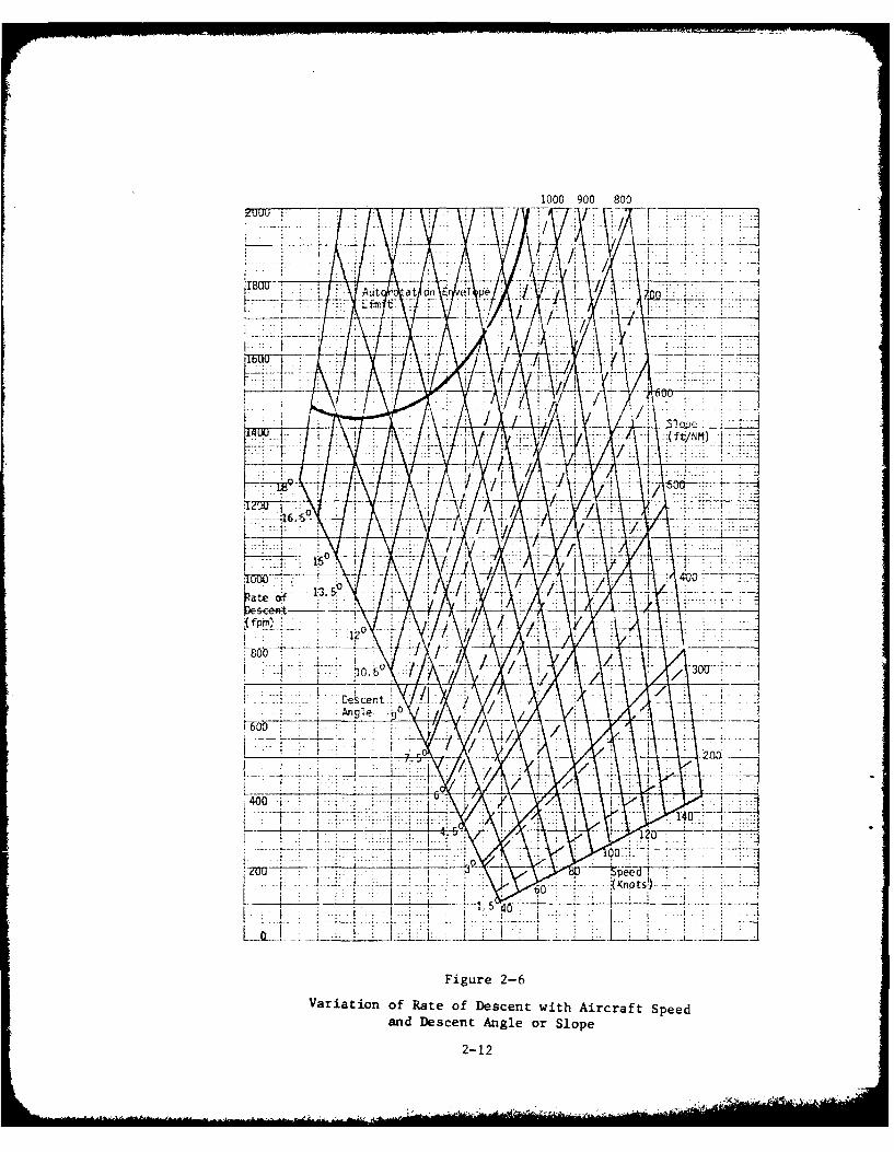
become practical for MLS supported precision approaches. Figure 2-6 shows
the relationship of rate of descent (ROD) to either descent angle or slope
and airspeed over the total range of IFR airspeeds.
Visual Approach Segment Profiles
The steeper approaches, which can be made possible through use of MLS,
require consideration of not only helicopter performance during the
approach to decision height, but also the visual continuation segment from
2-11
1000 900 800
7 I-IT
KJ.
2-12
decision height decelerating to hover. National Aeronautics and Space
Administration Technical Note (NASA TN) D-8275, "A Parametric Analysis of
Visual Approaches for Helicopters" provides excellent insight into the
characteristics of normal, visual helicopter approaches. Utilizing four
very different helicopters, representative of all but the very heaviest
members of the helicopter community, "normal" approaches were flown from
three different initial airspeeds--50, 80, 100 knots--and three different
initial altitudes--500, 1,000, 1,500 feet. A variety of pilots were used
and all were proficient in the helicopters flown. Pilots were instructed
to maintain initial altitude and airspeed until they desired to initiate
deceleration and/or descent toward the point of intended landing. All were
instructed to fly as though there were commercial passengera embarked and,
thus, to avoid abrupt maneuvers. The intent of the study wab tn accurately
define parameters of comfortable, desirable approach profiles freely chosen by
the subject pilots in order to establish a useful data base for improvement of
helicopter instrument approaches. The resulting approach profiles proved to
be essentially independent of pilot or aircraft type. Consequently, it is
possible to generalize the characteristics of desirable approach profiles.
Descent angles ranged from approximately 60 - 120. The steepest approaches
were associated with slowest entry speeds and the two highest entry altitudes.
Descent angles became progressively more shallow as entry speed increased. It
may be inferred from these data that the optimum descent angles range between
6 and 90 but that angles up to 12 were acceptable. No approaches
involved angles significantly steeper nor more shallow than this range.
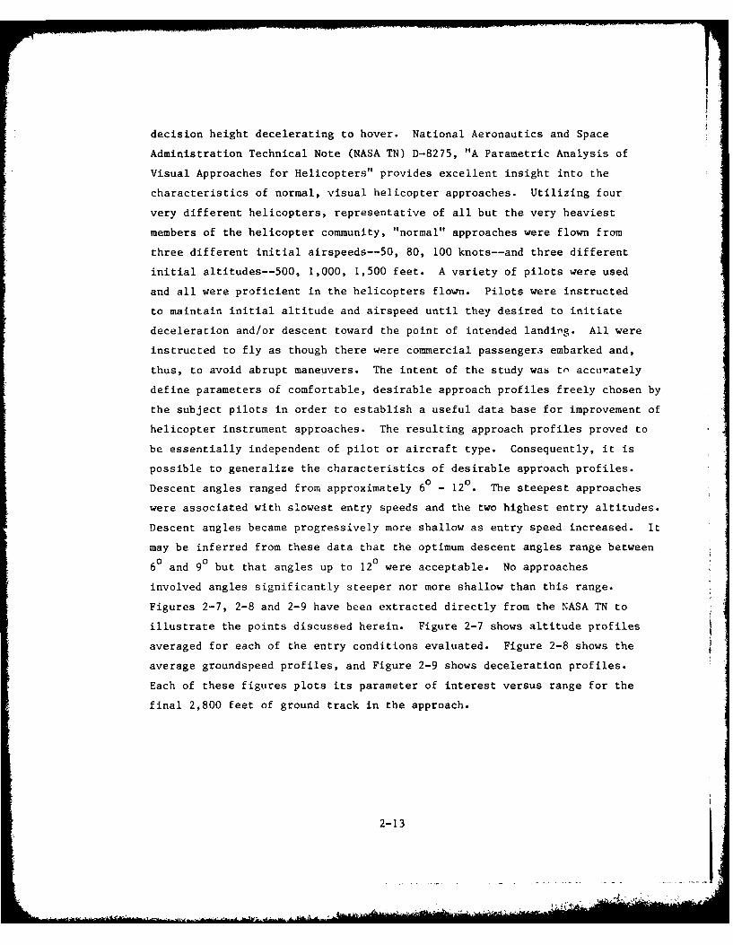
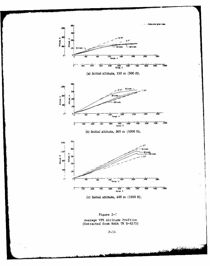
Figures 2-7, 2-8 and 2-9 have been extracted directly from the NASA TN to
illustrate the points discussed herein. Figure 2-7 shows altitude profiles
averaged for each of the entry conditions evaluated. Figure 2-8 shows the
average groundspeed profiles, and Figure 2-9 shows deceleration profiles.
Each of these figures plots its parameter of interest versus range for the
final 2,800 feet of ground track in the approach.
2-13
400- -Reference glide sloe
1200-
300-
Boo-- & *
4D- 100 t knot "Oltf 's 100k nots
0L 0 400 800 1200 1600 200 2400 2800Range, m
0 1003 2000 3802 M~ 50 6 7?j 81 9 lRange. If
(a) Initial altitude, 150 m (500 ft).
400-
S400~
0 400 803 1200 1600 2030 2400
Range, m
0 100 2000 3800 44000 50 600 ? o 400Range. It
(b) Initial altitude, 300 m (1000 ft).
1600r 50
E 100 knots
* 300 -
000
z 200 -
0 0 400 0 100 2 1 600 Z00 2400 28DU1Range. m
r. 1000 2000 3000 4WD0 5000 6000 70))000 m 9400 1000Range, ft
(c) Initial altitude, 450 m (1500 ft).
Figure 2- 7
Average VFR Altitude Profiles(Extracted from NASA TN D-8275)
2-14
60[ 150 M M It I
d$OmIg00ft 30D m (IWO0 It)
0o 10 20 3i0 400 A60 60 70 960 1000Range, mn
o 400 800 w 120 600 M( 2400 2800 3200Range. II
(a) Initial approach airspeed, 50 knots.
80- 150 Mn 1500 ftl300 M 0 000 t I
S60- 450 i15M t)
o 100 00 300 400 500 60 00 90 0l
Range m
0 400 80 20 10 00 240 2800 312WRange It
(b) Initial approach airspeed, 80 knots.
IOOF 150OMnl500 It)
300 Mn 111Y.00
0 0 i00 2w0 1200' 1600 2000 -AF0 -soo800 320Range. rt
(c) Initial approach airspeed, 100 knots.
Figure 2-8Average Ground-Speed Profiles(Extracted from NASA TN D-8275)
2-15

AA
a 1-
U
6 IoI ICc
00
U4;J
0~ r~.-
xo. '
5 ~1
uCu
05 A j
U9 lit to*~-
07 . .
o 4 0 I,- In In
-PO" 3 0 NG
2-1-
..........
Advantages Of Steeper Precision Approaches
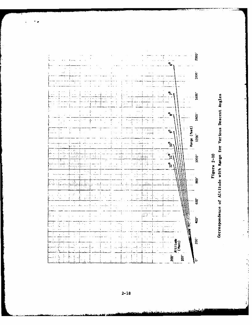
Two advantages would result from steeper approaches in the 60 -
120 range of descent angles. First, the perspective of the landing site
gained at decision height would be normal and confortable requiring no
abrupt transition maneuvers to complete the visual segment of the approach.
Second, consider the nature of an isolated heliport. As an example, assume
a 200 foot decision height (DH) approach; Figure 2-10 illustrates the corres-
ponding runway visual range (RVR) necessary to see the point of intended
landing (hover) upon reaching DH. With an RVR requirement of 1,200 feet,
these data imply that descent angles slightly greater than 90 will be
required to ensure sighting of the landing point upon reaching DH. With more
shallow approach gradients, the landing point may be beyond visual range; and
some form of guidance will be needed along the approach path to aid the
helicopter pilot during the visual segment of his approach. Positioning of
heliports often precludes installation of visual aids along the approach path
(e.g. rooftop heliports or offshore platforms). Therefore, approach gradient
can be tailored to permit the final approach to deliver the helicopter at DH
in a natural position to complete the approach from within the prescribed RVR
minimum. Approaches steeper than 120 can be considered, but further investi-
gation is essential to ensure that the visual segment will comfortably connect
with the instrument segment of the approach. Of significaat concern in
approaches steeper than 120 will be cockpit cutoff interference with visual
perspective at DH. Approaches more shallow than 60 have a long history of
success using ILS. It should be remembered, though, that the ILS approaches
have generally provided visual segments with approach lights and runways to
lead the helicopter pilot onward to his landing site. Precision approaches
slightly steeper than the norm for ILS are now accommodated by helicopter
TERPS, which prescribes minimum decision heights of 100' for descent angles
(glide slopes) of 3.80 or less, 150' for descent angles between 3.810 and
5.7° and 200' for descent angles greater than 5.70 . A limiting airspeed
of 90 knots (maximum) is also imposed. It is the intent of these constraints
to permit adequate time upon reaching decision height to initiate deceleration,
check the rate of descent and arrive comfortably over the intended point of
landing. Before addressing these points further, several parametric relation-
ships concerning approach to hover will be introduced.
2-17
- - - - - --
00
-------.----- - - ---------- . .- .....
... - . - ---- --
... . . . . .. . . . . . .
. . . . 14
2-18
Parametric Analysis Of Helicopter Approach Performance
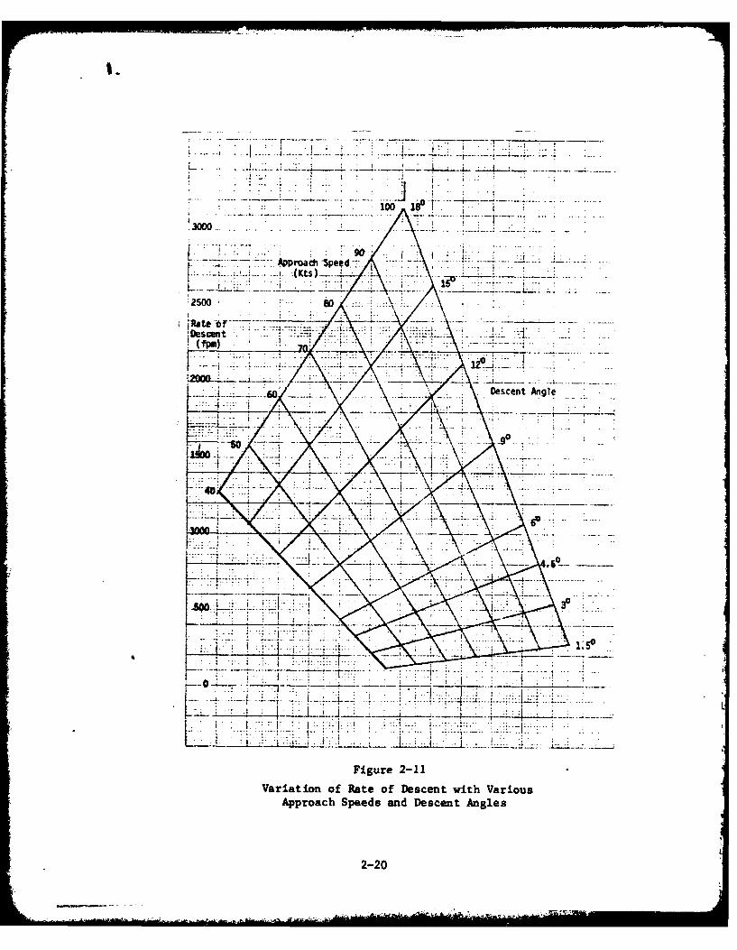
Figures 2-11 through 2-15 introduce a series of parametric analyses
into aspects of helicopter performance. Input parameters used in these
figures are predominantly descent angle and approach speed to define the
corresponding values of associated ROD in Figure 2-11, approach time or
time to ground impact in Figure 2-12, distance covered in Figure 2-13 and
mean deceleration rate in Figure 2-14. Figure 2-15 uses descent angle and
peak deceleration rate to define power requirements. These figures are
based on very simple computations solely to define the nature of the
relationships shown and the order of magnitude which should be expected.
The characteristics of no particular helicopter have been used as a basis
for these data. Normalized equations were used and appropriate parameters
chosen to eliminate the need for displaying such parameters as weight.
Figure 2-11 results from simple trigonometric relationships in which
approach speed is the speed along the flight path. Figure 2-12 is based on
an assumption of a constant deceleration rate which may be more conveniently
considered to be the mean deceleration rate. Two output time variables are
shown. The left margin depicts approach time between the assumed 200 foot
DH and the hover based on the mean deceleration rate necessary to sustain
the descent angle. The right hand margin depicts the time between a 200
foot DH and ground impact if DH goes unnoticed and flight is continued
without modification of approach speed or descent angle. Figure 2-13
depicts the ground distance between DH and hover for various descent angles
which are maintained throughout the visual approach segment. Figure 2-14
identifies the mean deceleration rate necessary to reach a hover along a
constant descent angle from 200 foot employing a specific approach speed to
DH. Figure 2-15 provides an estimate of the peak power necessary to
decelerate to a hover associated with descent angle and the expected
deceleration rate. In employing Figure 2-15 an expected deceleration rate
1.5 time greater than the mean determined from Figure 2-14 should be used.
This thumb rule is justified by inspection of Figure 2-9, which shows that
the maximum deceleration rate occurs just before reading hover and is typ-
ically about 1.5 times the mean. Figure 2-15 also required an estimate of
2-19
.4. .- -.--. -....... .
10001..
Aproach 3pee4 ---.
Ruatebr-
Descent Angle _
-go.
...............................
Figure 2-11Variation of Rate of Descent with Various
Approach Speeds and Descent Angles
2-20
0*- 2
Time
200 With .- . . .- . . -. Approach 100
Deceleration ~.Time to(Seconds) .. .Ground
- Wi thout-, Aproac - .2 . .Decelerationi
* Speed> -. . . - (Seconds) 80
70' Angle
........................ O
the- plte approac spe toahvrteeortn ln
Figure 2-12
VOETmsa r aeo 00 eiion ofiht ApproachTieoIpctie
th didescent anggle foTaius Approh Spds orsImaesim
Fiu2-12
17
I.4.
.1 -i - .
'es4e9 ......
2-2
1.5
, 0
2 4. so .
Figure 2-14Variation of Required Mean Deceleration Rate with Approach Speed
and Descent Angle (Employing Constant Deceleration from 200' to Hover)
2-23
- -- - - .............. . .6
7 7
04*1 .cc
4.hcc
Iag
$4 0 0
-- --- --- -
400
w sIK> c-. cm
II. w24 44
2-24
hover performance in its construction. For these purposes a hover-figure-
of-merit of .6 has been arbitrarily assumed to ensure that the added power
for deceleration is presented in appropriate proportion to the total power
needed to hover. Hover-figure-of-merit is the ratio of the theoretical
power required to hover to actual power required which considers such factors
as friction and accessory losses and tail rotor power. The .6 value is
typical of modern helicopters operating near gross weight. A better or
higher figure of merit would increase the ratio of needed power for deceler-
ation to hover power and a lesser or worse figure-of-merit would reduce that
ratio. The Figures 2-11 through 2-14 assumed constant deceleration or defined
a necessary mean deceleration. Figure 2-15 should be entered with a maximum
deceleration based on 1.5 times the mean defined by Figure 2-14.
As an example in using these charts, assume that we wish to evaluate a
90 approach angle maintaining 70 knots to DH. Figure 2-11 shows that the
associated rate of descent is 1100 feet per minute. Figure 2-12 shows that
the visual segment at constant deceleration would take 22 seconds for a 200'
decision height. That figure also shows that a failure to react at decision
height would result in ground contact 11 seconds after passing through 200'.
Figure 2-13 shows that 1280' would be the distance made good over the ground
while continuing on the 90 glide slope. Figure 2-14 shows that the mean
deceleration rate required would be .17g. To estimate the peak acceleration
the mean rate of .17g is multipled by 1.5 yielding .26g. Figure 2-15 shows
that a 90 glide slope with .26g maximum deceleration results in a peak power
during the approach 6 1/2% greater than that required to hover.
IRecommended Extension To Helicopter TERPS Approach Criteria
Returning to the helicopter TERPS criteria previously introduced,
descent angles of 3.80, 5.70 and 7.60 flown at the 90 knot maximum
allowable airspeed for "Copter Only" approaches results in rates of descent
of 605, 906 and 1207 fpm respectively. These descent rates and the corres-
2-25

ponding decision heights of 100, 150 and 200 feet each define an interval
of ten seconds between DH and ground impact if descent should continue
unabated. A ten second time interval should be adequate for missed
approach initiation even if a two second delay in execution is assumed at
DH. Referring again to NASA TN D-8275, analysis of the data presented in
Figure 2-7 reveals that all approach profiles flown converged on a flight
path which brought the helicopter through a gate about 50-60 feet above the
intended point of landing with 35-40 knots of ground speed and a 500
fpm ROD. Each approach profile based on the present TERPS criteria can
readily achieve the deceleration required to converge on the visual pro-
files defined by the NASA tests. It must, of course, be assumed that the
modest power margins required are, in fact, available.
For approaches to be flown at descent angles greater than 7.60, it
is recommended that TERPS criteria require a reduction in the maximum
approach airspeed to permit use of a 200 foot DH while retaining the ten
second time margin inherent in the current criteria for more shallow
approaches. As an example of such a steep approach, a 120 glideslope
would require 55-60 knots airspeed (Figure 2-12) and not more than .2g
(Figure 2-14) mean deceleration. If peak deceleration 1.5 times the mean
is assumed, this example would use a maximum of about 9% more power to
decelerate (Figure 2-15) than would be needed once hover is achieved. The
approach would be completed 20 seconds after reaching DH (Figure 2-12) and
would advance 970 feet over the ground from DH to the hover point (Figure
2-13).
Departure/Missed Approach Phase
Departure and missed approach share many of the same considerations.
IFR departure, however, first involves acceleration to obtain milimum IFR
airspeed; missed approach rarely involves an acceleration requirement.
Figure 2-16 displays the time required for level acceleration, and Figure
2-17 displays the corresponding distance required. Power margins required
2-26
IV i
CL 4JtA D
to -1
W ~ ~~~ - --- 0
0
4J
so0
OD -I
2-27

%00
4)0
-4 J
4D.
4 C) 0
CMl
d- "-4
0CC0
di 4D
ev0
2-28
may again be determined from Figure 2-15 using the 00 descent angle
since power required to accelerate and decelerate is equivalent. Accelera-
tion from hover may be readily approximated by a simple step increase to a
constant acceleration rate; thus, for example .4g acceleration in level
flight from hover needs about 7% more power than needed while stationary.
Constant acceleration is readily sustainable since power required diminishes
as airspeed increases (assuming a no wind hover initially). A .4g accelera-
tion in purely level flight would result in an uncomfortable nose down0rotation of approximately 20 . Most flight manuals recommend a more
modest rotation of 100 and an accelerating shallow climb until reaching
takeoff safety speed (V TOSS) or airspeed for best rate of climb. The
level acceleration profile and step acceleration rate input are used to
approximate the more sophisticated normal procedure.
Climb for departure differs from climb for missed approach in only one
aspect. No discrete considerations are included in helicopter TERPS for
climbout on departure. Consequently, helicopters are governed by normal
airplane requirements even though leaving a heliport, and a 40:1 criterion
applies in defining the climb surface. Rates of climb corresponding Co
this requirement are shown with corresponding ground speeds in Figure 2-4.
On the other hand, a "Copter Only" missed approach may use a climb surface
with a 20:1 gradient. Rates of climb corresponding to this requirement are
shown with corresponding ground speeds in Figure 2-3. Data contained in
Appendix A show that the maximum rate of climb for helicopters is obtained
at airspeeds ranging from 50 to 80 knots (calibrated airspeed). Rates of
climb are shown in Appendix A for each of the IFR helicopters summarized
therein with the corresponding recommended climb airspeed. Climb perfor-
mance data are shown for maximum continuous power; therefore, more power
would be available to initiate a missed approach or to accelerate after
takeoff. Inasmuch as climb performance is very sensitive to changes in
altitude, gross weight and temperature, carpet plots of these variations
are also provided in Appendix A based on maximum continuous power and best
rate of climb airspeed. These plots clearly show that some combinations
of performance parameters preclude sufficient rates-of-climb to sustain the
2-29
missed approach or departure gradients. Generalizations based on climb
performance alone do not define a useful performance envelope analogous to
the limitations in rate-of-descent definable by autorotation chararteris-
tics. There is, however, a consistent relationship between hover perfor-
mance and climbing performance. To illustrate this relationship, hover
performance boundaries have been plotted across the carpet plots contained
in the summaries of Appendix A. These boundaries are plotted for both HOGE
and HIGE conditions (where data are published for both) and define hover
performance limits based on combinations of the same three parameters which
impact climb performance. Consequently, superposition of the hover bound-
aries on the carpet plots of climb performance permits instant comparison
of climb capability with hover capability. It can be seen through evalua-
tion of the performance summaries that HOGE capability ensures sufficient
power to climb compatibly with a 20:1 gradient for those aircraft capable
of IFR operation at the airspeed for best rate of climb. HIGE capability
does not provide the same assurance, but does demonstrate compatibility
with a 40:1 gradient with the same restriction. These comments, of course,
assume no wind conditions as the worst case. Too much tail wind can, in
all cases, degrade climbout gradient unacceptably. These characteristics
imply that flight plannning which ensures HOGE capability at all enroute
stops will concurrently ensure adequate climb capability to execute IFR
missed approach at each stop. However, this insurance may not apply if
airspeeds significantly higher than speed for best rate of climb are
utilized. Figure 2-3 shows that rate of climb requirements to maintain the
20:1 gradient increase rapidly with increasing airspeed. The required
increase is 5 feet per minute per knot of groundspeed. Since the surplus
of power which may be applied to climbing flight is reduced when airspeed
is increased, as well, it becomes doubly important for helicopter pilots to
maintain an appropriate climb speed during "Copter Only" missed approach
procedures. Flight planning to ensure HIGE will also ensure sufficient
climb capability to satisfy 40:1 departure climb gradients, but accelera-
tion to minimum IFR airspeed or best rate of climb airspeed will require a
reasonable horizontal distance if takeoff is conducted near the hovering
performance limit.
2-30
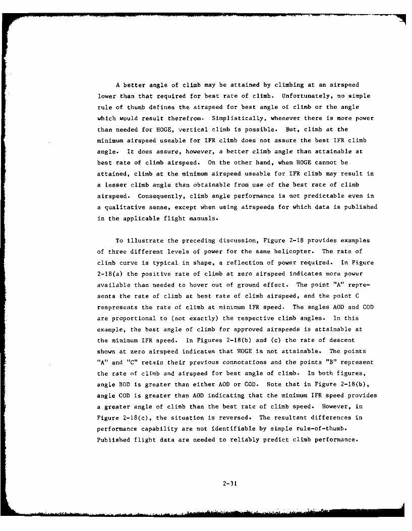
A better angle of climb may be attained by climbing at an airspeed
lower than that required for best rate of climb. Unfortunately, no simple
rule of thumb defines the airspeed for best angle of climb or the angle
which would result therefrom. Simplistically, whenever there is more power
than needed for HOGE, vertical climb is possible. But, climb at the
minimum airspeed useable for IFR climb does not assure the best IFR climb
angle. It does assure, however, a better climb angle than attainable at
best rate of climb airspeed. On the other hand, when HOGE cannot be
attained, climb at the minimum airspeed useable for IFR climb may result in
a lesser climb angle than obtainable from use of the best rate of climb
airspeed. Consequently, climb angle performance is not predictable even in
a qualitative sense, except when using airspeeds for which data is published
in the applicable flight manuals.
To illustrate the preceding discussion, Figure 2-18 provides examples
of three different levels of power for the same helicopter. The rate of
climb curve is typical in shape, a reflection of power required. In Figure
2-18(a) the positive rate of climb at zero airspeed indicates more power
available than needed to hover out of ground effect. The point "A" repre-
sents the rate of climb at best rate of climb airspeed, and the point C
respresents the rate of climb at minimum IFR speed. The angles AOD and COD
are proportional to (not exactly) the respective climb angles. In this
example, the best angle of climb for approved airspeeds is attainable at
the minimum IFR speed. In Figures 2-18(b) and (c) the rate of descent
shown at zero airspeed indicates that HOGE is not attainable. The points
"A" and "C" retain their previous connotations and the points "B" represent
the rate of climb and airspeed for best angle of climb. In both figures,
angle BOD is greater than either AOD or COD. Note that in Figure 2-18(b),
angle COD is greater than AOD indicating that the minimum IFR speed provides
a greater angle of climb than the best rate of climb speed. However, in
Figure 2-18(c), the situation is reversed. The resultant differences in
performance capability are not identifiable by simple rule-of-thumb.
Published flight data are needed to reliably predict climb performance.
2-31

Rate o f -- Rate ofCl imb l b
D_
Rate of Rate ofDescent ..r Descent
Airspeed -0 Airspeed -*
(a) (b)
DRate ofClimb
Rate ofDescent
0Airspeed-.
(c)
Figure 2-18. Variation of Rate of Climb with Airspeed(Undimensioned typical curves)
2-32
SUMMARY OF HELICOPTER PERFORMANCE
Data extracted from the flight manuals of a broad spectrum of IFR
helicopters are contained in Appendix A. These data reveal the general
character of the performance of IFR capable helicopters showing that all
are limited by current certification requirements to minimum IFR airspeeds
(40-60 knots) only slightly below the minimum power speeds which are
associated with the best rate of climb (ROC) and minimum ROD during auto-
rotation. From a practical point of view, autorotation may be found to
limit the descent capability of modern, IFR helicopters, as a class, to ROD
approximately 1000 fpm near the minimum IFR airspeeds and to ROD generating
descent angles of 8 or less as Vne is approached. ROC varies sosignificantly with altitude, gross weight, and air temperature that all
helicopters studied fail to be able to sustain positive ROC for some
combinations of these parameters. However, combinations of these three
parameters which assure HOGE capability were found also to ensure a suf-
ficient ROC to satisfy TERPS missed approach climb gradient requirements
(20:1) for "Copter Only" approach procedures provided the airspeed for best
ROC is employed.
Within the scope of current certification requirements it was found
that there are advantages to "Copter Only" approaches employing descent
angles up to 120 in terms of improved compatibility with the approach
profiles normally employed under VMC. Such steep approaches also move the
intercept of DH and the approach path to a point which can be within RVR
minimums. This last characteristic will benefit heliports so located that
approach lighting placement would be impractical. It was found that
airspeed should be reduced below the current "Copter Only" maximum of 90
knots when the glideslope becomes steeper than 7.60.
2-33/34
SECTION 3
FUTURE DEVELOPMENTS
INTRODUCTION
This section attempts to forecast future development in helicopter
procedures for TERPS. In attempting to define the nature of future changes,
the concerns of a wide spectrum of the helicopter operating industry have
been reviewed. It was found that industry appears to focus its interest
on three basic changes: that block time be minimized, that terminal minimums
be reduced to the lowest possible values, and that navigation and approach
aids should ideally be as self contained as possible. (This latter issue
is beyond the scope of the present discussion.) Of the first two issues,
the greatest interest was shown in reduced minimums, reflecting a desire
for increased mission dependability. Interest was shown in reduction of
both ceiling minimums and visibility minimums. Consequently, two aspects
of performance attain especial significance, steeper approaches to more
readily ensure obstacle clearance and lower airspeed to sustain or reduce
ceiling and visibility requirements in conjunction with steeper approach
paths.
The potential changes of interest center on exploitation of the low
speed flight regime of helicopters in which instrument flight is pursued on
the "back side of the power curve", i.e., speeds below the speed for
minimum power and mostly below the current "minimum IFR airspeed". For
purposes of discussion in this section, this flight regime will be referred
to as "slow flight".
This slow flight regime, which includes the ability to hover
downwind or crosswind, is the aspect of flight which distinguishes heli-
copters from airplanes. To be sure, airplanes do fly on the back side of
their power curves but, under normal circumstances, only briefly during
acceleration on takeoff or the final stages of landing. Helicopters have
3-1
operated VMC in this flight regime to great advantage enabling landing and
departure at confined sites, utilization as an airborne crane, or very slow
patrolling operations. An almost infinite variety of similar tasks can be
predicated on the demonstrated ability of helicopters to land and takeoff
vertically, hover for prolonged periods at a point in space, or fly in
precisely controlled but very low speed motion. Most such operations seem
inconsistent with instrument meteorological conditions except for takeoff
and landing. The whole objective of the NAS is to foster safe movement of
aircraft in IMC. It seems only logical, then, to pursue every reasonable
opportunity to extend that capability to exploit rather than inhibit these
unique characteristics of helicopters by opening the slow flight regime
more fully to terminal operations in the NAS, thus fostering the helicopter
operators quest for greater mission dependability.
HANDLING QUALITIES IN SLOW FLIGHT
Each civil helicopter, for which performance is summarized in Appendix
A, has imposed upon it a minimum IFR airspeed. Below these speeds the
aircraft are not certificated for instrument flight, yet they must rou-
tinely operate under VMC in that slower flight regime and do so quite
successfully. Several factors influence these certification limits, most
of which are not made manifest in either the type certificate or the flight
manual. Handling qualities in slow flight are judged to be unsatisfactory.
Why? They are judged to be unsatisfactory in relationship to the cues
available for instrument flight. This permits postulation of two attacks
on the problem--improve the handling qualities or improve the cues.
Probably a combination of these two approaches is most reasonable.
Instrumentation and Cues
The most significant cues lost in IFR flight at slow speed are those
which relate a sense of motion to the pilot. In VMC, visual cues are
provided by various aspects of the scene including peripheral vision. The
typically expansive window areas of helicopters permit instant perception
3-2
A J
of changes in velocity laterally, vertically and longitudinally. These
cues are developed by movement relative to objects; thus they are 'round-
speed related. In IMC they can be generated by doppler radar systems or by
synthesis from precision positioning information such as MLS with distance
measuring equipment (DME). Mere readout of rate is helpful, but does not
synthesize the tertiary aspect of the background relative motion sensed
through peripheral vision. Slow speed three axis rate information has been
displayed to military pilots in ASW missions for many years, but manual
control with this limited degree of cue augmentation has proven to be very
difficult. A form of display analogous to the peripheral visual scene
would enhance utilization of rate cues and reduce workload.
Slow Flight Performance
Helicopter performance characteristics are determined by airspeed, not
groundspeed. A fundamental problem in helicopter slow flight is airspeed
measurement. Certification standards for both transport and utility heli-
copters are carefully worded to permit use of conventional pitot-static
systems by helicopters for measurement of airspeed. This was a pragmatic
choice, when the standards were established, inasmuch as no alternative
airspeed indicating systems were available. Nevertheless, the consequence
has been, and remains so with such systems, that helicopters do not have a
reliable indication of airspeed in slow flight. This is true when the
helicopter is moving directly into the wind with the pitot tube aligned
with the relative motion; the problem becomes more pronounced when lateral
components of relative motion are introduced. There is no provision for
measuring the direction of relative motion with conventional pitot-static
tube airspeed indicating systems, only the magnitude of the velocity and
that imperfectly at low speeds or with sideslip. Current requirements
specify measurement of airspeeds ranging upward from about 30 knots (for
Part 29 multi-engine helicopters) or 80%, of climbout speed (for Part
27 and single engine Part 29 helicopters). Consequently, helicopter pilots
have never enjoyed a truly valid basis for assessing aircraft performance
in slow flight, since they have used mostly groundspeed rather than air-
speed cues.
3-3
These airspeed instrumentation considerations affect the significance
of handling characteristics. For example, trim may vary through the slow
flight regime in such a manner that the same combinations of attitude and
cyclic stick position apply to trimmed flight at more than one airspeed.
Such characteristics are clearly unsatisfactory when no airspeed measurement
is available to provide a basis for correlating expected aircraft response
to control inputs. However, if airspeed were reliably (i.e., promptly and
repeatably) displayed in vector form (either direction and magnitude or
orthogonal components), these adverse trim characteristics would become far
less significant. With such instrumentation, it would become more important
to consider any discontinuities in control position or force gradients tha.,
merely their sense and magnitude. Flight demonstration with adequate
airspeed measurement is needed to establish handling quality criteria
appropriate to IMC operation more fully into the slow flight regime.
Control Augmentation
Handling qualities may be directly improved for slow flight although
this is not a simple task. The significant trim changes which occur in the
slow flight regime result from the transition of rotor wash from a vertical
flow to a nearly horizontal flow and the related development of two vortices
along the wake in translational flight. The significant changes in flow
move across the aircraft body and interact with various parts of it to
produce pitching and yawing moments which build and fade throughout the
transition. Thus, trim characteristics are innately variable in the
slow flight regime. Augmented flight control systems could be devised to
isolate the pilot from these variations and produce trim force and position
gradients acceptable under the present standards. Alternatively (or
additionally) approaches could be directly coupled to remove the pilot from
the control input loop during the slow flight phase of approach. However,
programming a control system to perfora either of these functions on a
repeatable basis requires a performance measurement system that accurately
senses the total nature of the flight condition, namely a low airspeed
direction and velocity measurement system as just discussed.
3-4
Army Experience
The U.S. Army at Fort Monmouth has conducted tests of decelerating
instrument approaches using a four cue flight director system. Success has
been claimed for the system in both manual and coupled precision decelerating
approaches to hovering flight for glideslopes ranging between 30 and 120.
The approach aid is a military MLS system with precision DME which provides
localizer, glideslope, range and range rate to the aircraft for processing by
the flight director computer. Test results were summarized before the American
Helicopter Society (AHS) at the 35th Annual National Forum in May 1979 in a
paper entitled, "Advances in Decelerating Steep Approach and Landing for
Helicopter Instrument Approaches". All approaches reported upon were based on
use of a constant initial approach speed of 60 knots (range rate along glide-
path) and deceleration rate of 0.05g. Consequently, the slant range for the
deceleration phase of each approach was 3125 feet and the elapsed time 62.5
seconds for all glideslope angles. The resulting height above touchdown
for initiation of the deceleration phase varies as the sine of the glide
0 0slope from 164 feet for 3 to 650 feet for 12 . Initial airspeed was
unreported, but necessarily varied as a function of wind velocity to establish
the 60 knot initial range rate.
The aircraft utilized was an unspecified single engine version of the
UH- I series which would closely approximate the flying characteristics of
the Bell Model 212 reported on in Appendix A. This implies that the
reporting agency, the U.S. Army Avionics R&D Activity (AURADA) was satis-
fied with the man/machine performance that resulted from use of the pilot
cues presented by the four cue flight director in the slow flight regime
below the 40 knot minimum IFR airspeed which applies to the Bell 212. The
cues utilized provided commands in pitch, roll and collective throughout
the approach profile and yaw below 45 knots airspeed.
3-5
APPROACH PROFILES IN SLOW FLIGHT
If the issues involving certification criteria for slow flight are
resolved, decelerating approaches in IMC to much lower minimums than now
utilized will become practical considerations. Two questions remain, the
first of which is not germane to this discussion. First, the quality of
the supporting navigation system must permit positioning of the aircraft in
three dimensions to the accuracy required for safe operations at each site.
(Heliports may be as small as 1.5 rotor diameters for the largest helicop-
ter to be operated.) Second, approach profiles must be defined which are
within the safe performance capabilities of the aircraft.
Height-Speed Envelope Considerations
Performance capabilities germane to questions of slow flight are
summed up for each helicopter in its limiting height-speed (H-V) envelope.
A set of composite height-speed envelopes for the helicopters summarized in
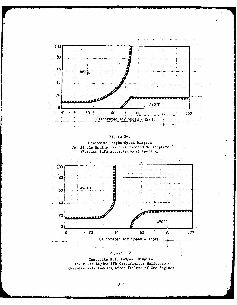
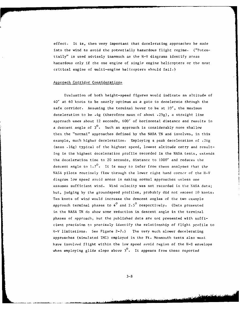
Appendix A is shown as Figures 3-1 for single engine helicopters and 3-2
for multi-engine helicopters. It can be seen from these figures that the
present performance of multi-engine helicopters permits slightly higher
safe hover height and significantly reduced airspeed. The low altitude,
high speed portions of the two composite H-V envelopes are essentially
equivalent. Limiting H-V performance is the source of some consternation
for slow speed IMC operations. Prudence would seem to require that an IMC
approach to a hover should require a somewhat greater hover height than a
normal, VMC approach. For example, the U.S. Navy uses a hover height of 40
feet (over water) for its IMC operations in the antisubmarine warfare (ASW)
mission. Yet, the H-V diagrams imply that a limit of 10-15 feet would
predominate among current helicopters. Furthermore, the decelerating
approach path would encroach, at least marginally, on the "avoid" regimes
in reaching a hover at such heights. Wind considerations have not been
central to any of the earlier discussion; they now become especially
significant. Notice that Figures 3-1 and 3-2 are based on calibrated
airspeed. A headwind, in effect, blows the leading edge of the "avoid"
area away. Conversely, a tail wind would have the undesirable opposite
3-6
100
80 -
460
.60 AVOID , • - " --- l .... -- . .i"-
. 4..- 0 -------...
-0O 20 40 i 0 80 100
Calibrated Air Speed -Knots -i
Figure 3-i
Composite Height-Speed Diagramfor Single Engine IFR Certificated Helicopters
(Permits Safe Autorotational Landing)
100
I ----
60 ' ; AVOID -
20
0O 20 40 60 80 100
Calibrated Air Speed - Knots
Figure 3-2
Composite Height-Speed Diagramfor Multi Engine IFR Certificated Helicopters
(Permits Safe Landing After Failure of One Engine)
3-7
effect. It is, then very important that decelerating approaches be made
into the wind to avoid the potentially hazardous flight regime. ("Poten-
tially" is used advisely inasmuch as the H-V diagrams identify areas
hazardous only if the one engine of single engine helicopters or the most
critical engine of multi-engine helicopters should fail.)
Approach Corridor Considerations
Evaluation of both height-speed figures would indicate an altitude of
40' at 60 knots to be nearly optimum as a gate to decelerate through the
safe corridor. Assuming the terminal hover to be at 10', the maximum
deceleration to be .4g (therefore mean of about .25g), a straight line
approach uses about 12 seconds, 600' of horizontal distance and results in
a descent angle of 3° • Such an approach is considerably more shallow
then the "normal" approaches defined by the NASA TN and involves, in this
example, much higher deceleration. Employing a peak deceleration of .24g
(mean .16g) typical of the highest speed, lowest altitude entry and result-
ing in the highest deceleration profile recorded in the NASA tests, extends
the deceleration time to 20 seconds, distance to 1000' and reduces the
descent angle to 1.70. It is easy to infer from these analyses that the
NASA pilots routinely flew through the lower right hand corner of the H-V
diagram low speed avoid areas in making normal approaches unless one
assumes sufficient wind. Wind velocity was not recorded in the NASA data;
but, judging by the groundspeed profiles, probably did not exceed 10 knots.
Ten knots of wind would increase the descent angles of the two example
approach terminal phases to 40 and 2.50 respectively. (Data presented
in the NASA TN do show some reduction in descent angle in the terminal
phases of approach, but the published data are not presented with suffi-
cient precision to precisely identify the relationship of flight profile to
H-V limitations. See Figure 2-7.) The very much slower decelerating
approaches (simulated IMC) employed in the Ft. Monmouth tests also must
have involved flight within the low speed avoid region of the H-S envelope
when employing glide slope above 30. It appears from these reported
3-8

tests and from analysis of the necessary performance characteristics that
it is neither practical nor desirable to consider the H-V envelope as an
aircraft limitation during landing approach.
Very Steep, Constant Speed Approaches
The future portends a requirement to support not only helicopters, but also
advanced V/STOL aircraft which will have their own particular performance
limitations. It has been characteristic of high disc loading V/STOL
aircraft to date that vertical landing is usually initiated from a high
hover, out of ground effect and typically of the order of 100 feet above
the point of landing. Takeoff usually involves a rapid, primarily vertical
ascent to a similar altitude before initiating transition into forward
flight. Two factors have generated the need for those profiles, neither of
which has any obvious solution that may permit future V/STOL aircraft to
emulate current helicopters in landing and takeoff maneuvers. These
characteristics are an adverse or negative ground effect sometimes referred
to as "suck down" and a propensity to recirculate the hot exhaust gases
into the engine intakes during flight in ground effect. The hot gas
recirculation can have an adverse effect on power available in a power
critical flight regime. Safety considerations are stimulating military
requirements to ensure sufficient power redundancy to permit safe landing
following engine failure within this high, slow flight regime.
Helicopters could equally well use similar arrival and departure
profiles, and to some advantage. Of course, similar considerations for
safety in the event of helicopter power failure would also be required.
Some multi-engine helicopters can now effectively demonstrate such redun-
dancy under certain loads. The distinct advantages of a high hover with
steep approach cone arrival and departure profiles results from the oppor-
tunity to always orient the slow speed flight directly into the wind. This
minimizes power required in the hover phase, ensuring a greater margin of
3-9
...
safety. Direction and magnitude of the airspeed vector are wanted cockpit
information for proper management of the flight profile. Helicopter pilots
will want it for determination of power margin. Pilots in jet V/STOL
aircraft will want it to avoid a hazardous limitation resulting from
slip-roll coupling.
We will briefly examine helicopter implications of such procedures.
Needed are H-V characteristics which essentially eliminate the high alti-
tude, low airspeed avoid areas shown in Figure 3-2. Inasmuch as orien-
tation can be maintained into the wind throughout the deceleration into a
high hover, and orientation on the steep approach cone can be varied to
ensure heading into the wind, a small avoid area of ten knots or less may
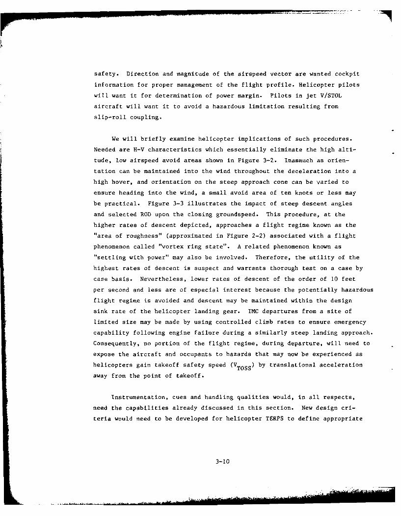
be practical. Figure 3-3 illustrates the impact of steep descent angles
and selected ROD upon the closing groundspeed. This procedure, at the
higher rates of descent depicted, approaches a flight regime known as the
"area of roughness" (approximated in Figure 2-2) associated with a flight
phenomenon called "vortex ring state". A related phenomenon known as
"settling with power" may also be involved. Therefore, the utility of the
highest rates of descent is suspect and warrants thorough test on a case by
case basis. Nevertheless, lower rates of descent of the order of 10 feet
per second and less are of especial interest because the potentially hazardous
flight regime is avoided and descent may be maintained within the design
sink rate of the helicopter landing gear. IMC departures from a site of
limited size may be made by using controlled climb rates to ensure emergency
capability following engine failure during a similarly steep landing approach.
Consequently, no portion of the flight regime, during departure, will need to
expose the aircraft and occupants to hazards that may now be experienced as
helicopters gain takeoff safety speed (VTOsS) by translational acceleration
away from the point of takeoff.
Instrumentation, cues and handling qualities would, in all respects,
need the capabilities already discussed in this section. New design cri-
teria would need to be developed for helicopter TERPS to define appropriate
3-10
----- ----- 2236
34 j:.TJ 1 T2 jI. 20
32a~ L 19
30 -18_ __
28 .1
2 6 -- ------ - ... ... 1615
2 4--------- - - ~ d 1
24 (~f ) -- .
22 1
20 -r1
188
-7 7
211
3-11
approach and departure paths and stipulate requirements for assurance of
supporting aircraft performance. Horizontal deceleration to hover followed
by gradual steep descent would reduce pilot workload significantly in
comparison to a simultaneously descending, decelerating approach along a
precision glide path; and steep descent would permit a constant, creeping
approach speed with ROD that is entirely compatible to the design charac-
teristics of the landing gear.
3-12
APPENDIX A
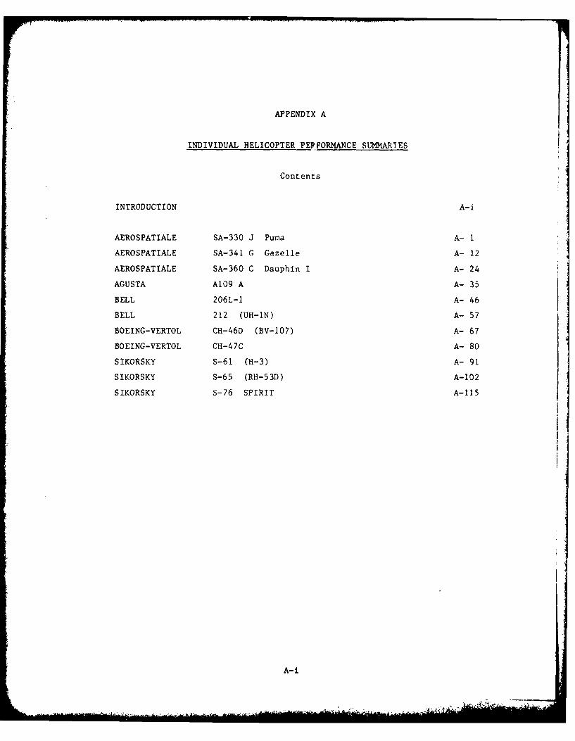
INDIVIDUAL HELICOPTER PEP FORMA1NCE SUMMARI ES
Contents
INTRODUCTION A-i
AEROSPATIALE SA-330 J Puma A- 1
AEROSPATIALE SA-341 G Gazelle A- 12
AEROSPATIALE SA-360 C Dauphin I A- 24
AGUSTA A109 A A- 35
BELL 206L-1 A- 46
BELL 212 (UH-1N) A- 57
BOEING-VERTOL CH-46D (BV-107) A- 67
BOEING-VERTOL CH-47C A- 80
SIKORSKY S-61 (H--3) A- 91
SIKORSKY S-65 (RH-53D) A- 102
SIKORSKY S-76 SPIRIT A-11 5
A-i.
APPENDIX A
INDIVIDUAL HELICOPTER PERFORMANCE SUMMARIES
INTRODUCTION
This appendix compiles performance summaries extracted from the flight
manuals of a group of IFR certificated civil helicopters plus a few IFR
capable military helicoters.
Each summary starts with an overview sheet which provides a picture
plus a listing of the most cogent descriptive characteristics. This is
followed by a narrative introduction which presents a more elaborate
general description.
Following the introductory narrative is a sheet of data on which are
listed the flight limitations which impact instrument flight rule (IFR)
performance. These data are extracted from many locations in the basic
flight manval and the IFR supplement, if applicable. Most such data are
published in the limitations sections of these sources. To complete orien-
tation to the aircraft, three view drawings with dimensions are provided.
The remainder of each summary consists of data which varies with one
or more parameters. Charts, graphs, or nomograms of the never exceed speed
(V ) and the height-speed (H-V) diagram are provided to show physicalNE
limitations on safely usable maximum and minimum airspeeds. PACER inter-
pretations of flight manual data present figures of the variation of
rate-of-descent (ROD) with airspeed in autorotation for that range of
airspeeds which includes minimum ROD and shallowest glide angle (therefore
maximum gliding distance). The remaining charts deal with climb performance.
The first chart shows rate-of-climb (ROC) and associated calibrated airspeed
(CAS) at maximum gross weight and a nearly empty gross weight. These data
represent sea level, standard day conditions as do the autorotation data.
A-ii
+I ' '-'+ + " .....- .... m... ... "".. ... ". '. iH
The last charts present the variability of ROC with altitude and gross
weight for two different temperature conditions - standard day and standard
day plus 20 C. These data are presented for maximum continuous power with
all engines operating and airspeed held at the prescribed best rate of
climb (BROC) airspeed. Carpet plots are employed to reflect the interre-
lationships of the two parameters in defining ROC. Superimposed upon the
carpet plots are boundary traces which represent the liUiting combinations
of gross weight and altitude that permit hover out of ground effect (HOGE)
and hover in ground effect (HIGE). Hover data are based on takeoff power.
The traces of these boundaries demonstrate the ROC which may be expected at
BROC airspeed for the combinations of altitude and gross weight which
reflect margiial hover capability. Any region above a boundary ensures
hover for the conditions specified by the boundary (in ground effect or out
of ground effect).
A-iii/iv 94
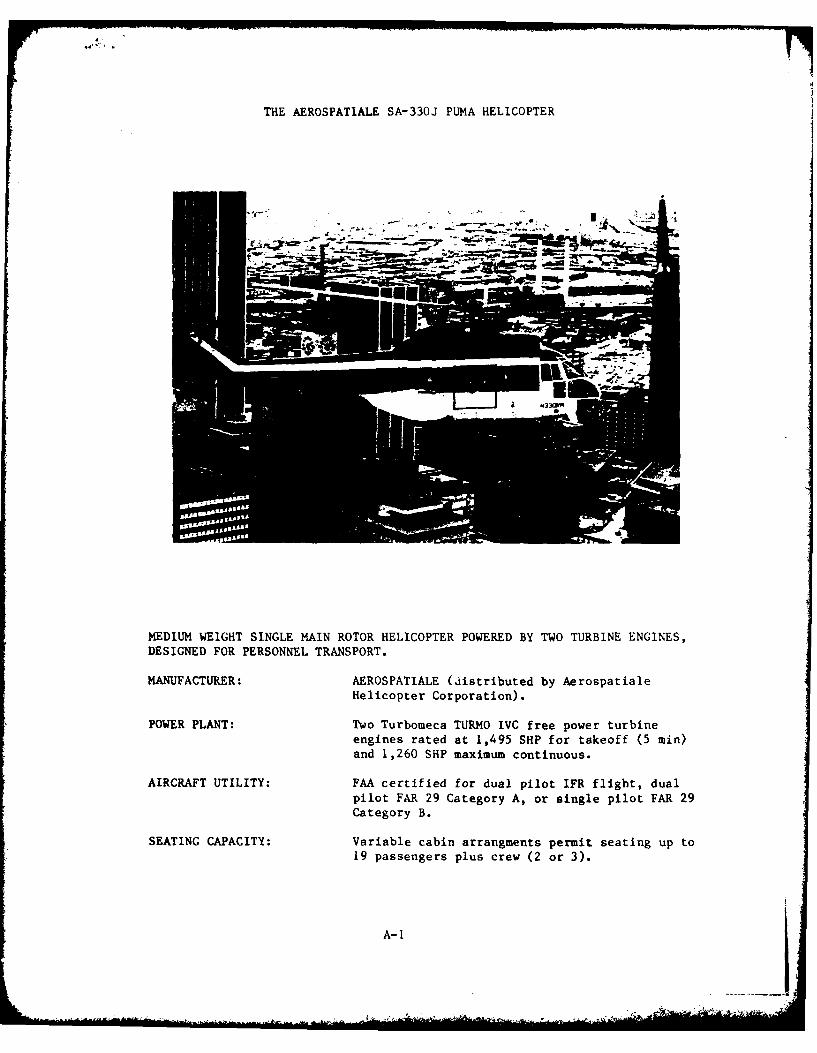
THE AEROSPATIALE SA-330J PUMA HELICOPTER
MEDIUM WEIGHT SINGLE MAIN ROTOR HELICOPTER POWERED BY TWO TURBINE ENGINES,DESIGNED FOR PERSONNEL TRANSPORT.
MANUFACTURER: AEROSPATIALE (distributed by AerospatialeHelicopter Corporation).
POWER PLANT: Two Turbomeca TURMO IVC free power turbineengines rated at 1,495 SHP for takeoff (5 min)and 1,260 SHP maximum continuous.
AIRCRAFT UTILITY: FAA certified for dual pilot IFR flight, dualpilot FAR 29 Category A, or single pilot FAR 29Category B.
SEATING CAPACITY: Variable cabin arrangments permit seating up to19 passengers plus crew (2 or 3).
A-i
INTRODUCTION
The SA-330J Puma is a 19 passenger medium helicopter manufactured bySociete Nationale Industrielle Aerospatiale of Marignane, France andmarketed in the U.S. by Aerospatiale Helicopter Corporation of GrandPrarie, Texas. The helicopter was originally designed for troop carryingand battlefield supply missions. It is used by the military of severalEuropean nations. (It is jointly produced with Westland HelicoptersLimited, UK).
The SA-330J is certificated under Type Certificate H4EU (Rev. 2) forTransport Category A and B operations and two pilot IFR operations. It isa compact single main rotor design with a four bladed main and five bladedanti-torque rotors. Retractable tricyle wheeled landing gear are used.
The aircraft is powered by two free power turbine Turbomeca TURMO IVCengines. Each engire is rated at 1,495 SHP (5 min limit) for normal dualengine takeoff operations and 1,260 SHP maximum continuous operations.Emergency ratings for operation of a single remaining engine permit 1,555SHP (2 1/2 min) or 1,380 SHP (30 min). The main gearbox is rated at 2,427SHP for dual engine takeoff and 1,742 SHP continuous rating (either singleor dual engine operations).
Performance data presented herein are extracted from the SA-330J PumaFlight Manual (approval date April 29, 1976).
A-2
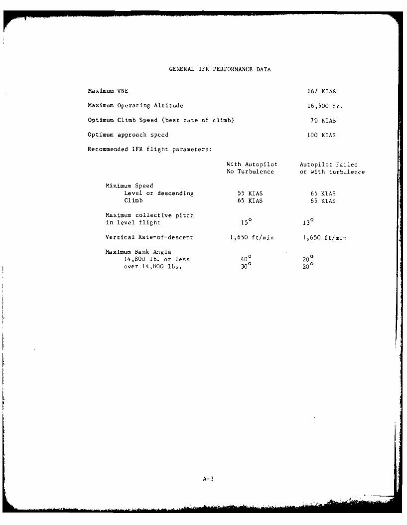
GENERAL IFR PERFORMANCE DATA
Maximum VNE 167 KIAS
Maximum Operating Altitude 16,500 fL.
Optimum Climb Speed (best rdte of climb) 70 KIAS
Optimum approach speed 100 KIAS
Recommended IFR flight parameters:
With Autopilot Autopilot Failed
No Turbulence or with turbulence
Minimum SpeedLevel or descending 55 KIAS 65 KIAS
Climb 65 KIAS 65 KIAS
Maximum collective pitch
in level flight 15° 130
Vertical Rate-of-descent 1,650 ft/min 1,650 ft/min
Maximum Bank Angle
14,800 lb. or less 400 200
over 14,800 lbs. 300 200
A-3
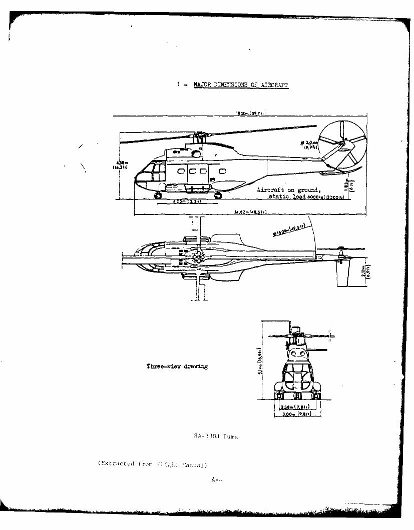
1-MAJOR DDOSIONS OF AIRCRAFT
0 /4
asf
(Extrstatic lrad Fl f.Ia Vauu
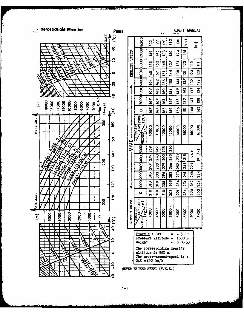
* w rospatiale iMlkaptifs Puma FLIGHT MANUAL
00
E-4z
Nr I
0 2 NN '0~O
0_
C> '0E -0 0 0 0
0 -- 00 0 C4
0 - -
0 z
N 0 - L -- Z
N N'4 C4 F
o. w K_0
(n w C4 10 V)C4(N (N C4
4 -(4 ~ 00 0000 00'
- ) 0 0 0000 00
0 In 2 " 0 " R0. Nv
11 0 Eample AT =- 5OPressure altitude = 1000 mweight w6000 kg
The corresponding density0 altitude is 500 a.
The never-exceed-speed is-CAS - 290 km/h.
nM EXCED SEE (V..E)
Ntc 7A0

1-4
250 4 A
* ..., ..... ..... _ _ _ _
20 5 b * 3 Ko
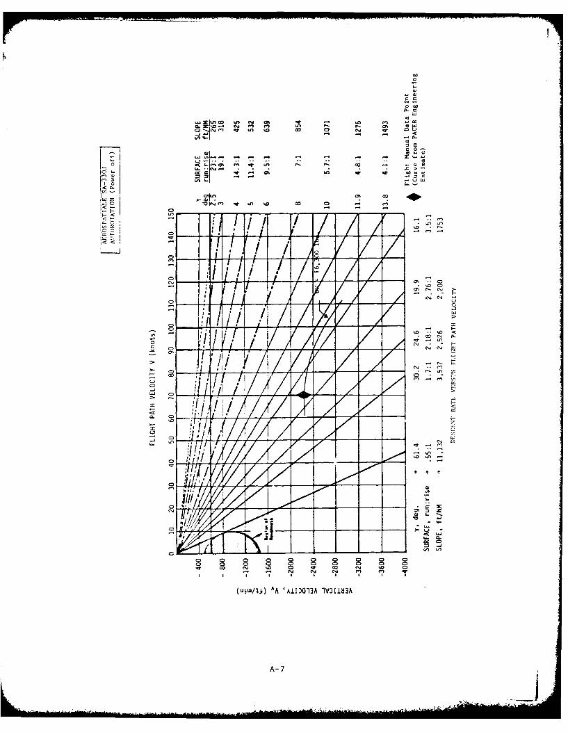
000
6.
c0
I~ o 0
~~~~l U) 1 c0es- -7-
.10. !
L.4~In v ,. 1 w
00'W ) OOX-~
<1- - 1. 4 1
cm V,/ I
C) , -
coj 04- C" r
A- 7
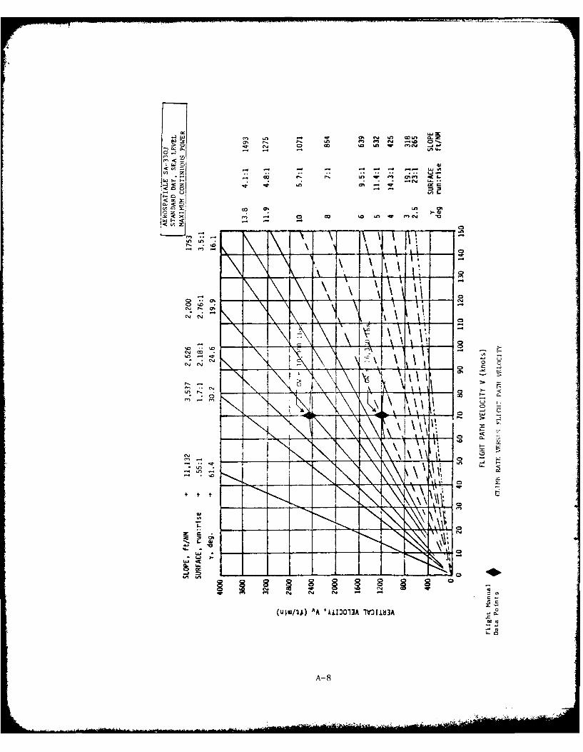
m. UUfU".-f 0-
0 N lj C.
O.- -l -I In-% L
r< c
x- 1c tI n r en C I4
Le 01
LI- \I' LUICD
n . I
- NIn
La.
NC
-j
..... ....
Climb Rates
The following two figures present carpet plots of the best rate of
climb attainable at optimum climb speed and maximum continuous power for
a spectrum of aircraft weight and pressure altitude. One figure presents
data for standard day performance and the other, hot day performance when
temperatures are uniformly 200C warmer than standard day at each altitude.
Two traces, one labeled HOGE (hover out of ground effect) Boundary and
the other, HIGE (hover in ground effect) Boundary, cross the carpet plots
to identify those combinations of gross weight and altitude at which hover
capability becomes correspondingly limited. (Hover performance is based on
dual engine takeoff power vice maximum continuous power.)
A-9

0 0 lC
Ln L)
C))
C.) 4x
.0 0i*-a cm LD.J.0
C) 0C. 0
04 -L.UC_ 0)S~ C
C, *'"C- A x0
CDD0 tv
r ll
7 .-.
00
o 0
c)-C)D
C) :j
04
0C
'.0
A-10
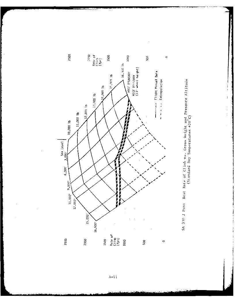
C, G
CVC
CC
C7 co 'o.
CL C-L 41
.C) C . .
C-)-C
C'N
C)CC) En
Cii
- 4C4
C)'
C) CCC
A- I I
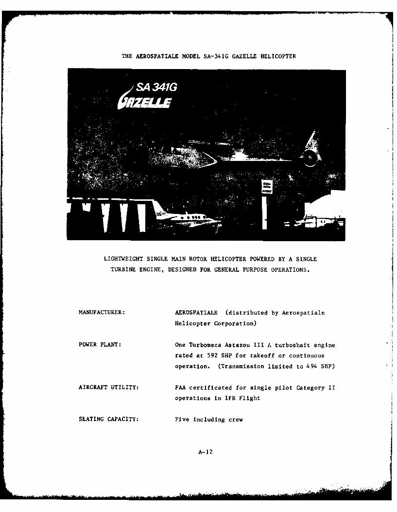
THE AEROSPATIALE MODEL SA-341G GAZELLE HELICOPTERA
LIGHTWEIGHT SINGLE MAIN ROTOR HELICOPTER POWERED BY A SINGLE
TURBINE ENGINE, DESIGNED FOR GENERAL PURPOSE OPERATIONS.
MANUFACTURER: AEROSPATIALE (distributed by Aerospatiale
Helicopter Corporation)
POWER PLANT: One Turbomeca Astazou III A turboshaft engine
rated at 592 SHP for takeoff or continuous
operation. (Transmission limited to 494 SHP)
AIRCRAFT UTILITY: FAA certificated for single pilot Category II
operations in IFR Flight
SLATING CAPACITY: Five including crew
A-12
INTRODUCTION
The SA-341G Gazelle is a five place (pilot plus four) light utility
helicopter originally designed for use by the French and British armed
forces. It is manufactured by the Helicopter Divison of Societe Nationale
Industrielle Aerospatiale of Marignane, France and marketed in the U.S by
Aerospatiale Helicopter Corporation of Grand Prairie, Texas.
The SA-341G is certificated under Type Certificate H6EU (Rev 3). With
appropriate supplemental type certificate(s), it can be certified for
single pilot IFR Category I (and Category II). It employs a single, fully
articulated, three-bladed main rotor and a multibladed fan-in-fin, or
fenestron, type of anti-torque tail rotor. Skid type landing gear is
employed.
The aircraft is powered by one, single spool Turbomeca Astazou IliA
engine rated at 592 SHP. The same rating applies for both takeoff and
maximum continuous power. The transmission i3 limited to 494 SHP. Again
takeoff and maximum continuous ratings are the same.
Performance data presented herein have been extracted from the SA-341G
Gazelle Flight Manual (approval date December 1974), IFR Supplement (dated
October 28, 1975) and Category II IFR Supplement (dated February 2, 1977).
A-13
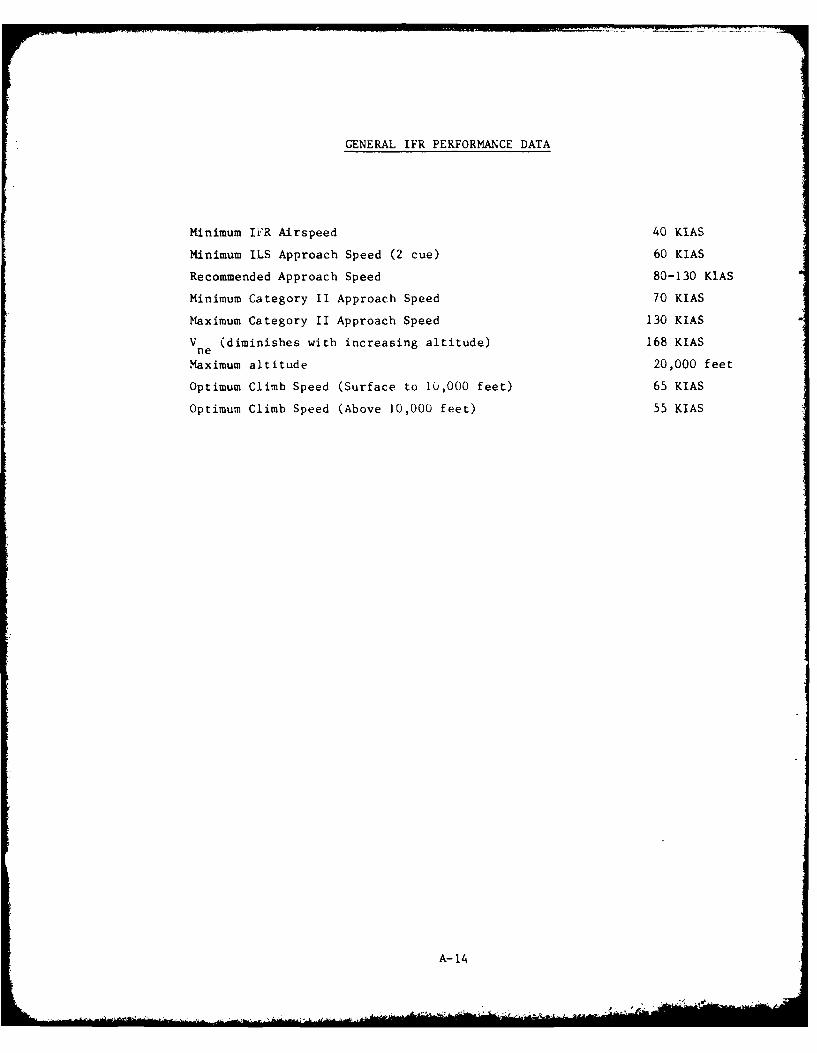
GENERAL IFR PERFORMANCE DATA
Minimum IiR Airspeed 40 KIAS
Minimum ILS Approach Speed (2 cue) 60 KIAS
Recommended Approach Speed 80-130 KIAS
Minimum Category II Approach Speed 70 KIAS
Maximum Category II Approach Speed 130 KIAS
V (diminishes with increasing altitude) 168 KIASne
Maximum altitude 20,000 feet
Optimum Climb Speed (Surface to 10,000 feet) 65 KIAS
Optimum Climb Speed (Above 10,000 feet) 55 KIAS
A-14
k__
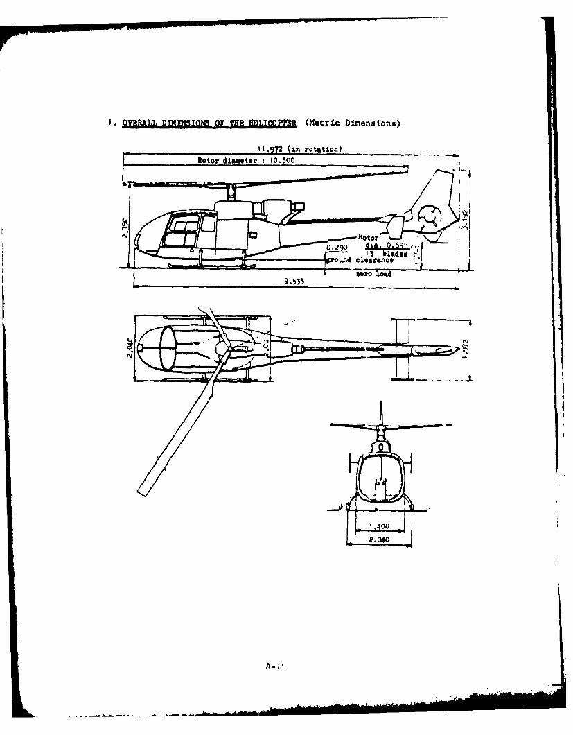
* VERLL D(DINS O1TI I.OPTERZ (Metric Dim~ensions)
-11.972 (Ln rotation)Rotor diaeter 1 10.500
9.533 -T sr U
A- i.
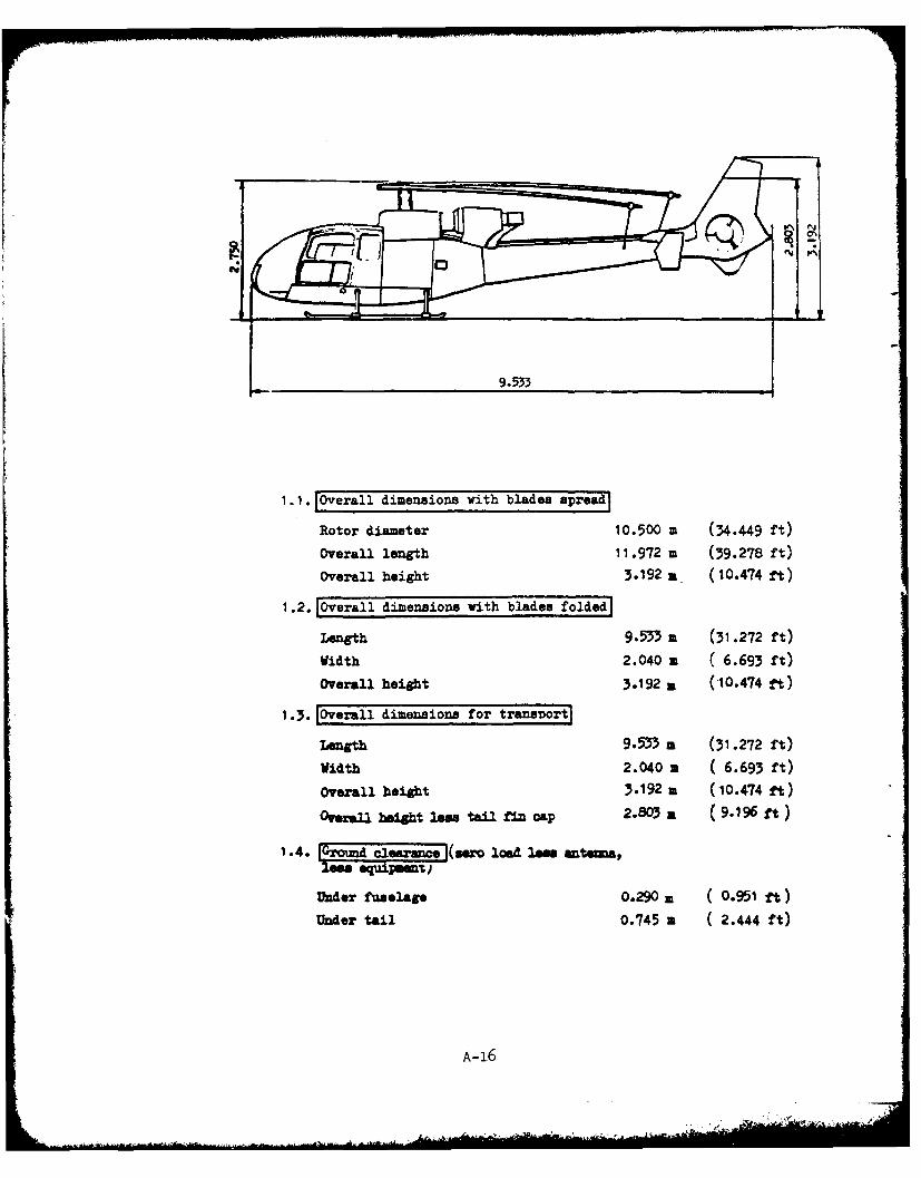
1.1.1Overall dimensions with blades spread]
Rotor diameter 10.500 m (34.449 ft)
Overall length 11.972 m (39.278 ft)
Overall height 3.192 a (10.474 ft)
1.2.1Overall dimensions with blades foldedl
Length 9.533 a (31 .272 ft)
Width 2.040 a ( 6.693 ft)Overall height 3.192 a (10.474 ft)
1.3. Overall dimensions for trans-Dort]
Length 9.533 a (31 .272 ft)
Width 2.040 m ( 6.693 ft)
Overall height 3.192 a (10.474 ft)
Overall huight leos tail fin cap 2.803 a (9.196 ft)
1.4. l~o(s-c~er-=p xo load low ante=&,less equipment)
Under fuselage O.2 9 0 2 0.951 ft)
Under tail 0.745 a C2.444 ft)
A-16
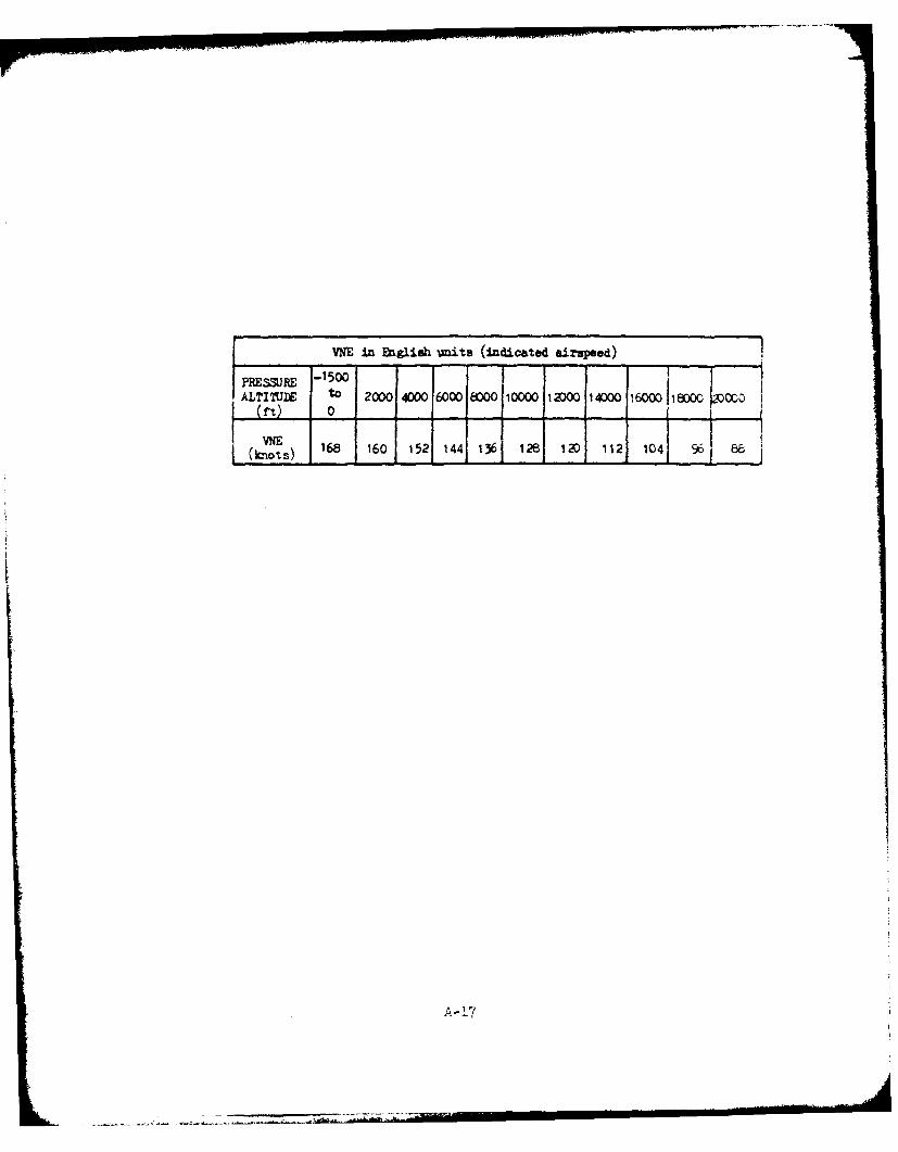
VNE in Engliah units (indicated airspeed)
PRSSR -1500IALTITUDE to 2000 400016000 8000 10000 12DO0 14000 i6000 18ow0 00~
(ft)
~ ~t) 168 160 1 521 144 1361 126,i 1 041 96 8 I
A-17

IAVOID CDNTI,.-hUU2 C-PEATION
0 00 - 1
200f
700
2001l - ----
,i~~r~ 1501 0A0
05 0 (m
50+$.
100-V2O~t cpar~at ~ wih3 Ea~r 7-aper
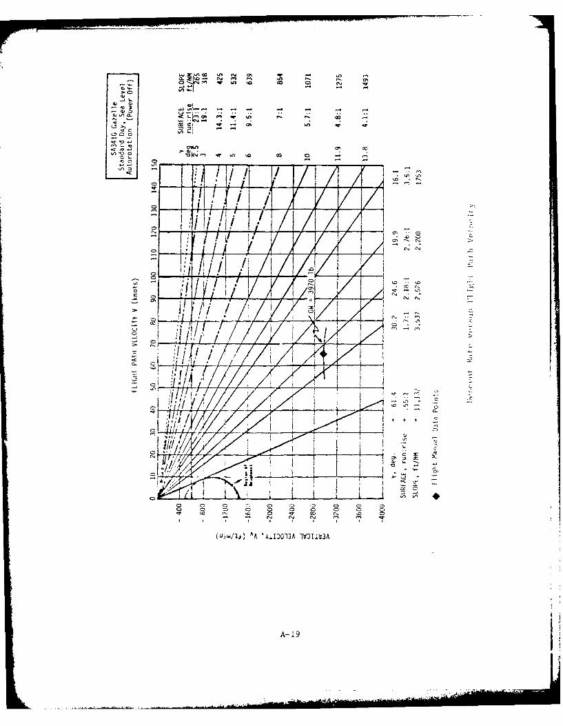
>01
0 qw . co ~00
0, C
C5~ I z C~ 1
0,
IFI
0 CD 0 0D 0 0 0 0 0
o~"C 0 0o0 0
A- 19
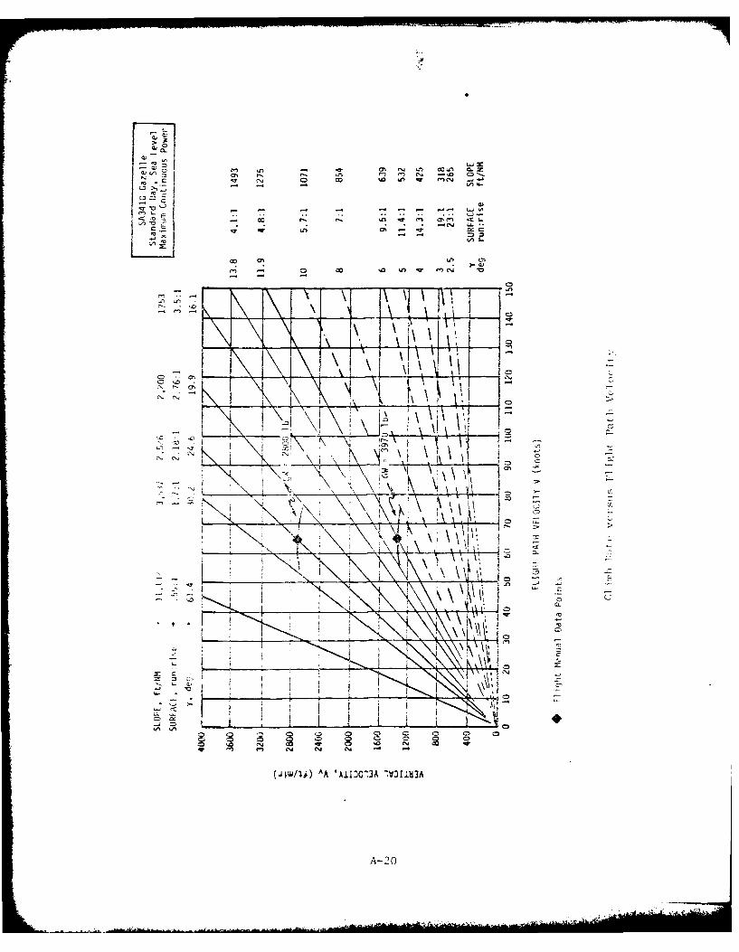
0 co w c4
1r C
i CL
oc
X X\
A-20
Climb Rates
The following two figures present carpet plots of best rate of climb
attainable at optimum speed and minimum continuous power for a spectrum of
aircraft weight and pressure altitude. One figure presents standard day
performance and the other hot day performance based on temperatures uni-
formly 200C warmer than standard day for all altitudes.
Each figure employs two carpets. The right hand carpet covers pressure
altitudes from sea level to 10,000 feet; the left hand, from 10,000 to
20,000 feet. The double presentation results from a power limit imposed on
the SA-341G below 10,000 feet. Two collective pitch control detents are
utilized in the flight control system. Collective pitch is not to be
increased beyond the first detent below 10,000 feet. Collective pitch up
to the second detent is permitted to 20,000 feet. In all cases transmission
torque limits are to be observed.
A-21
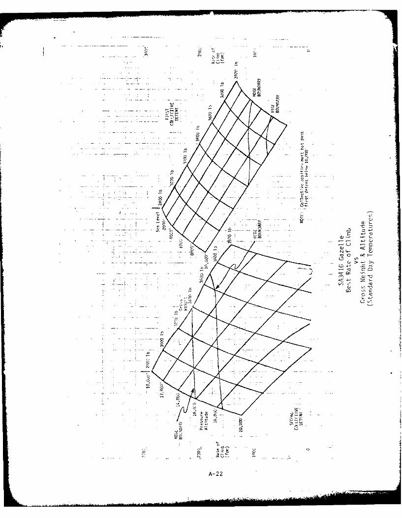
CCA
CIJI
CI CU
co _ - -Z!~-
A-22;
CM)
............. ...... 0.....
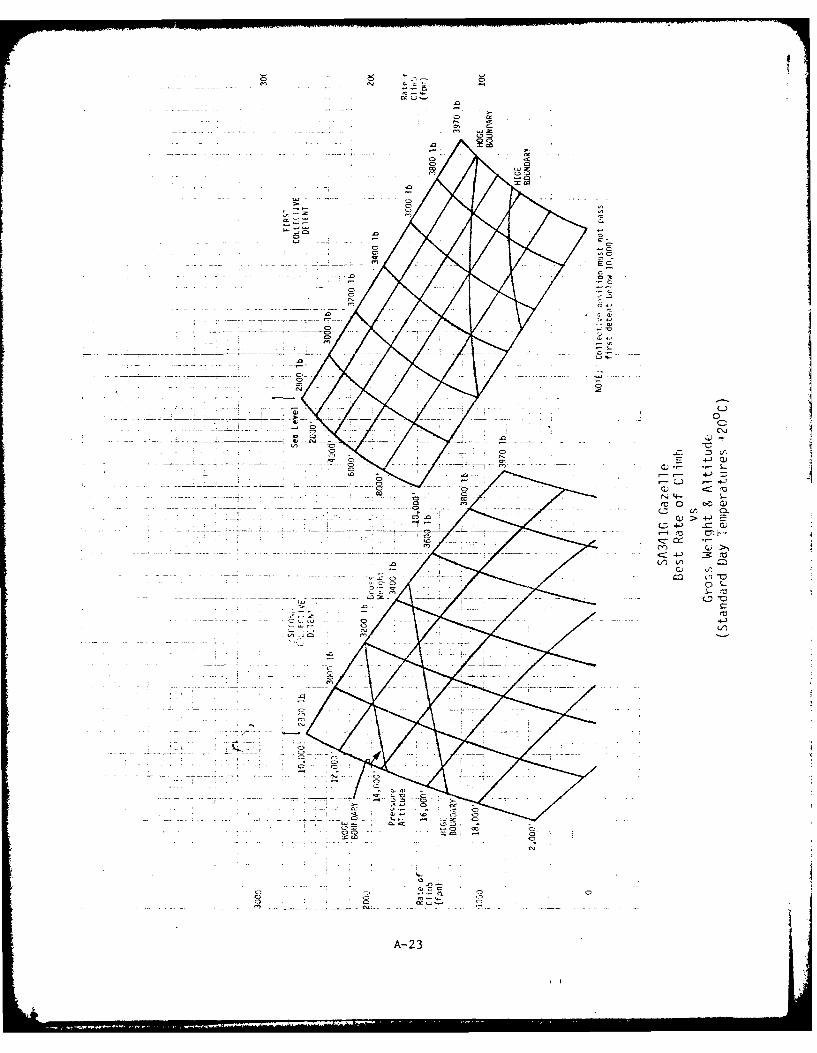
CD.
0 0
cn, C,.-
E 4-'
V ) > -
4-)
x- -- C,
A-230
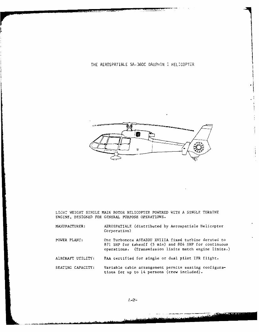
THE AEROSPATIALE SA-360C DAUPHIN I HELICOPTER
LIGHT WEIGHT SINGLE MAIN ROTOR HELICOPTER POWERED WITH A SINGLE TURBINEENGINE, DESIGNED FOR GENERAL PURPOSE OPERATIONS.
MANUFACTURER: AEROSPATIALE (distributed by Aerospatiale Helicopter
Corporation)
POWER PLANT: One Turbomreca ASTAZOU XVIIIA fixed turbine derated to
871 SHP for takeoff (5 min) and 804 SHP for continuousoperations. (Transmission limits match engine limits.)
AIRCRAFT UTILITY: FAA certified for single or dual pilot IFR flight.
SEATING CAPACITY: Variable cabin arrangement permits seating configura-
tions for up to 14 persons (crew included).
A-2 4
INTRODUCTION
The SA-360C Dauphin is a 14-place lightweight helicopter manufacturedby Societe Nationale Industrielle Aerospatiale of Marignane, France, andmarketed in the U.S. by Aerospatiale Helicopter Corporation of GrandPrairie, Texas. The helicopter is designed for general purpose uses in thecivil sector. (The U.S. Coast Guard has recently ordered a twin-enginevariant for their use; otherwise it is not used in any U.S. Militaryforces.) It has been FAA certificated for single pilot IFR when equippedwith an attitude hold SAS and for dual pilot IFR without SAS when dualcontrols and instruments are installed.
Standard configuration includes fixed wheel conventional landing gear,four bladed main rotor and fan-in-fin or fenestron enclosed tail rotor.
The SA-360C is powered by one Turbomeca ASTAZOU XVIIIA single spoolturboshaft engine. The engine has an integral reduction gear and auto-matic speed governor. The engine is flat rated at 871 SHP for takeoff (5min) and 804 SHP continuous. (Takeoff power is derated from 991 SHP).
Performance data presented herein are extracted from the Dauphin FlightManual (approval date December 21, 1976) unless otherwise noted.
A2
A- 25
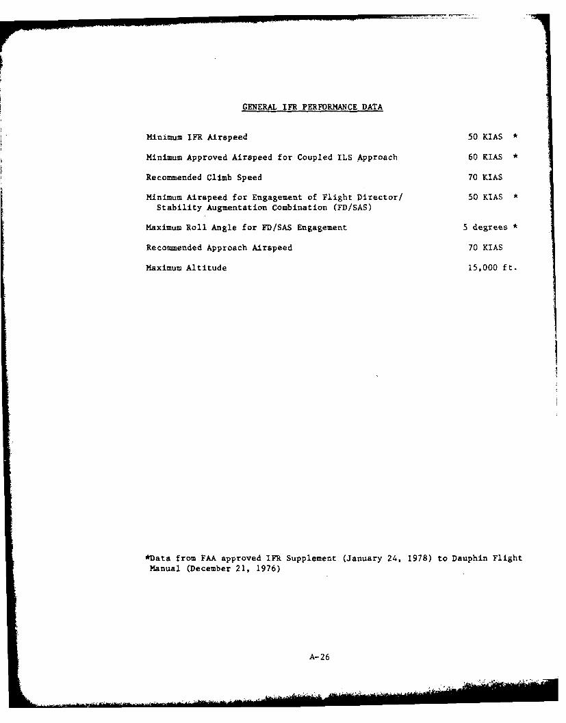
GENERAL IFR PERFORMANCE DATA
Minimum IFR Airspeed 50 KIAS *
Minimum Approved Airspeed for Coupled ILS Approach 60 KIAS *
Recommended Climb Speed 70 KIAS
Minimum Airspeed for Engagement of Flight Director/ 50 KIAS *Stability Augmentation Combination (FD/SAS)
Maximum Roll Angle for FD/SAS Engagement 5 degrees *
Recommended Approach Airspeed 70 KIAS
Maximum Altitude 15,000 ft.
*Data from FAA approved IFR Supplement (January 24, 1978) to Dauphin Flight
Manual (December 21, 1976)
A-26
' , ... , .'- ' ,;au.. -.- -*,, .'-l s ' -
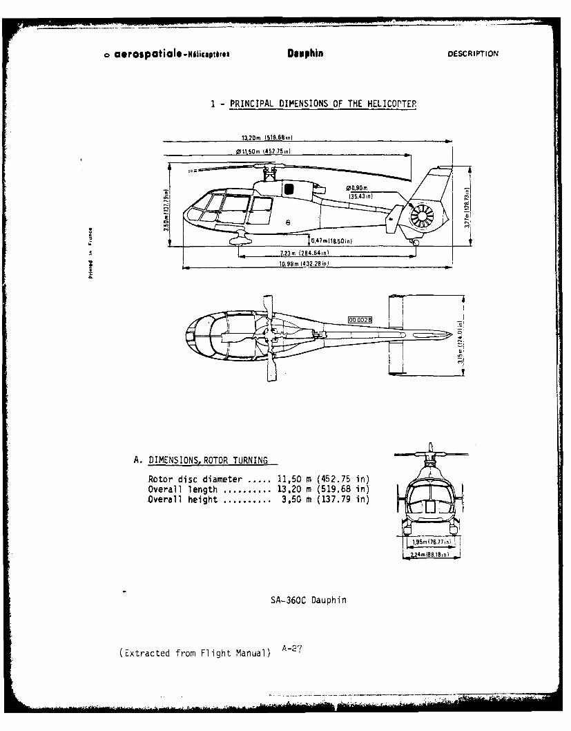
aerosptil -Nlicptits Dauphin DESCRIPTION
1 -PRINCIPAL DIMENSIONS OF THE HELICOPTER
13,20m 1519.68in)
Rotor dis ~ 01,50 diaete....750 45.5 n
00,90(6.7,n
0,4m(88.18 in)
SA-36C Dauph6in)
(Extactd fomFigh9Maua m 432.2in
A.~~ ~ ~ DIESOSOO TURIN
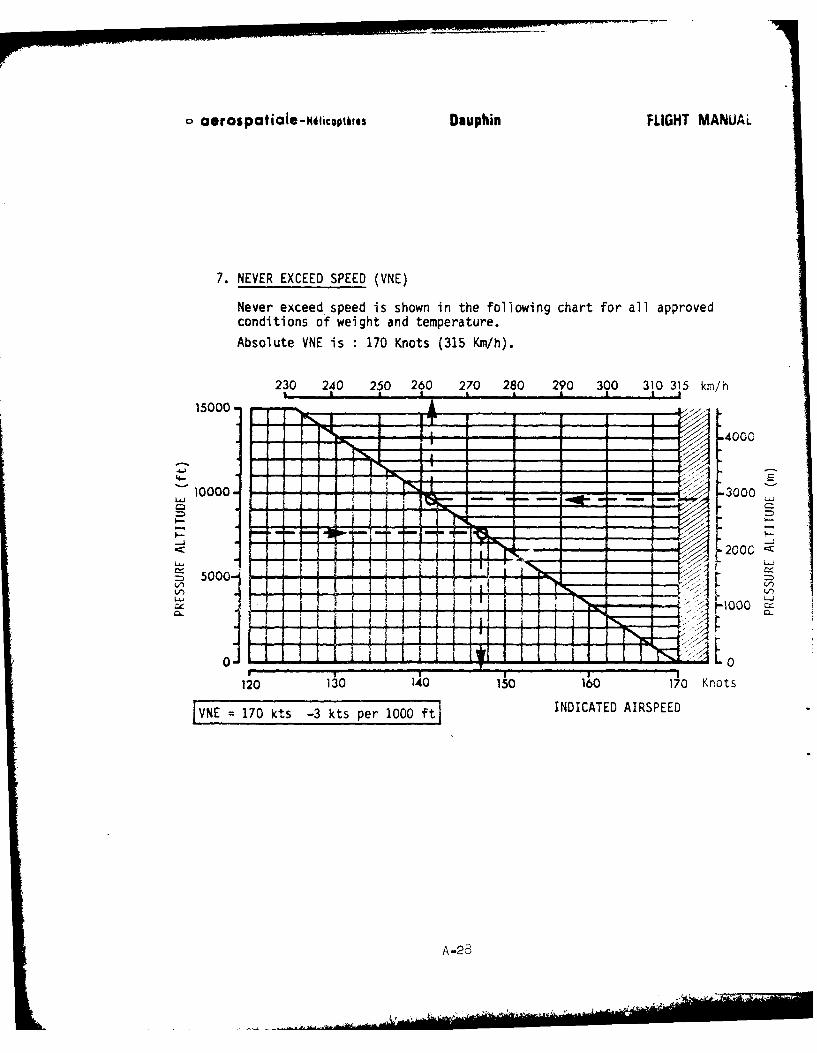
o aeraspaticle.-iw4icopites Dauphin FLIGHT MANUAL
7. NEVER EXCEED SPEED (VNE)
Never exceed-speed is shown in the following chart for all approvedconditions of weight and temperature.
Absolute VNE is 170 Knots (315 Km/h).
230 240 250 260 270 280 290 300 310 315 km/h
15000-
- - - - -4000
E
10000---- ~ - - - - -' 3000
__ -, t200C_
50001 z r t -~ F - -j
0- 0
120 130 10150 160 170 Knots
VNE =170 kts -3 kts per 1000f INDICATED AIRSPEED
A-28
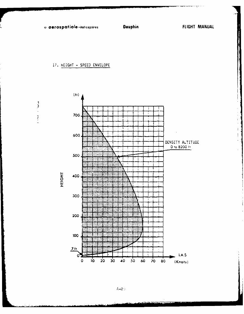
a erospaticie -Nolcoptirus Dauphin FLIGHT MANUAL
17. hEIGHT - SPEED ENVELOPE
(f 0
700 1
600
z DENSITY ALTITUDE
500
Z 400
30......... ... .. ...
200
0 0 0 0 40 50 60 7 8 (nos
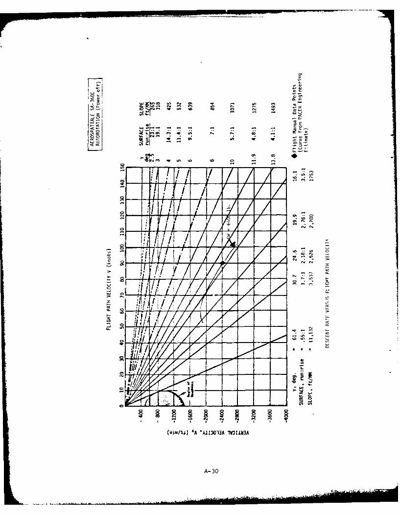
CO
LA~
C- -
La g 0
V1cr m w Gn G8- 0 u
- n LO
10
-%. -l
7 ~ ~
x -.
-jJ C'
- -5
40
A-3-
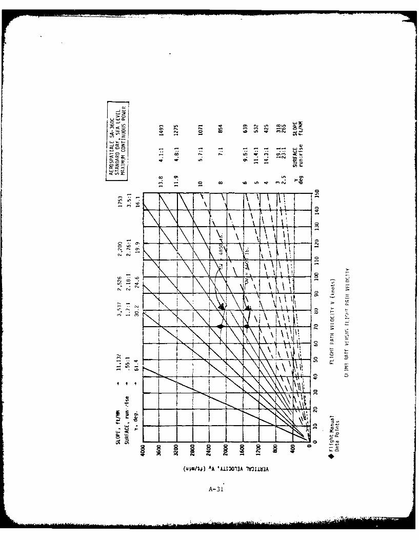
L ) L(40
C9 w! CA -co %D "M In m t~c'( V
(A u
C\. C a
- *. .61..1- "~ ~ . I C5 QeC c
* * -'4 TN
cn05
- UWj% AA 6 0 (A n SU
-A 3
- 1 0k
Climb Rates
The following two figures present carpet plots of best rate of climb
attainable at optimum speed and minimum continuous power for a spectrum of
aircraft weight and pressure altitude. One figure presents standard day
performance and the other hot day performance based on temperatures uni-
formly 20 0C warmer than standard day for all altitudes.
Each figure employs two carpets. The right hand carpet covers pressure
altitudes from sea level to 6,000 feet; the left hand, from 6,000 to 15,OOC
feet. The double presentation results from a power limit imposed on the
SA-360C below 6,000 feet. Two collective pitch control detents are utilized
i. the flight control system. Collective pitch is not to be increased
beyond the first detent below 6,000 feet. Collective pitch up to the
second detent is permitted to 15,000 feet. in all cases transmission
torque limits are to be observed.
A-32
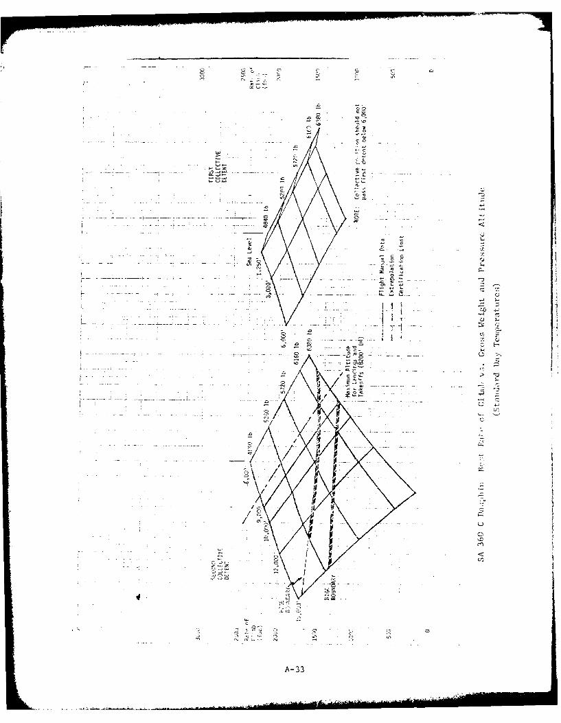
- aa a K--. ~ a
C- -A ~-. - -
0 0
~ ------ ~,---- 0 - a. -
* - -
0) 00
* a. ---. - --
0) 'C
------....... C ~0') 0 ..~- Ca** -
* -
a - Ot S- *J -- - a* 0 ~0' 0. -
- ---. ~S0.~.)~) -~ ---) 4-Q
1 - -
I' - - -a
S*i I~1------------.-----. ---------.---- ~'~2 -a
-0 -1~ .- '
Ii a-~ C)
g.j CE-
0 -C:C
a---- -cas, -
0/0 4-
C
C
V C.
I I '-. 4
/I
I- C-'
a (2(1
a- II Li-a
-'-'a ICC ~
V
c~., - * - 0 - 0
.0 $ - C
0 CU (N C) 0
A 33
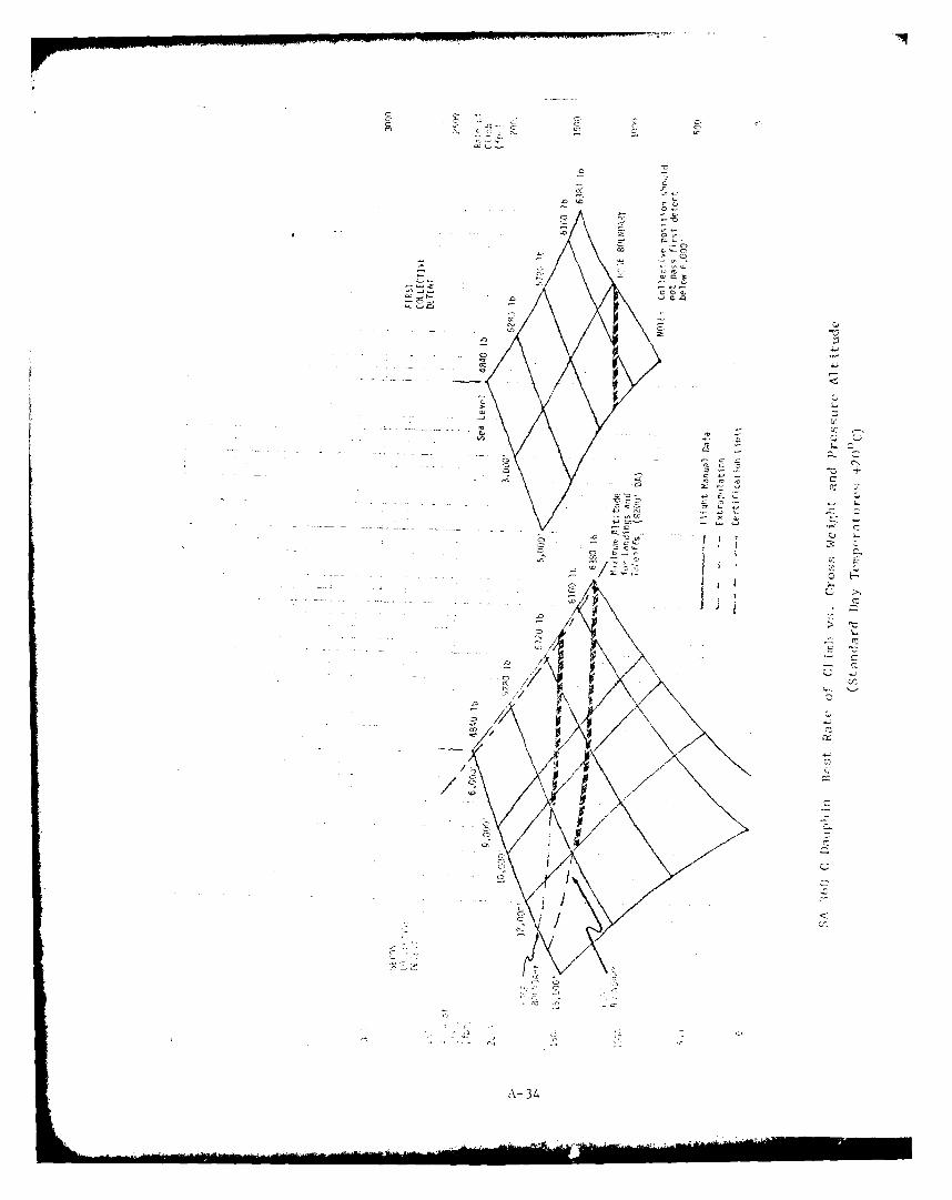
C -- -~C~C ~
cC CL
U - - Co
C,.- C> Ct
~ CCCL
- cCC-. ~
U
O -~0 C-.;
C CL-~ ~ CCC, C +CCC. CC CV CC
- - - CC' CC- C C 0.~CCC CC' CCCJ~i CCC CC CC C,,'CCCL - CC CL
CC - C-CC.,
.CL CCCCC-CrC., -- CC C-CC.CC CCC C~C-* C-
C QCCL C--
'C jiC
-/11-.
E -z
-'C--CCLC C-...'
cC
'-c'C
C,'
C' CO 'C
A-34
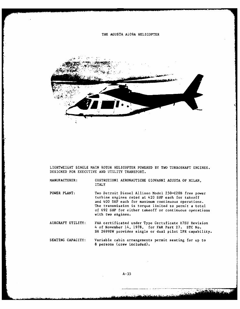
THE AGUSTA AI09A HELICOPTER
LIGHTWEIGHT SINGLE MAIN ROTOR HELICOPTER POWERED BY TWO TURBOSHAFT ENGINES.DESIGNED FOR EXECUTIVE AND UTILITY TRANSPORT.
MANUFACTURER: COSTRUZIONI AERONAUTICHE GIOVANNI AGUSTA OF MILAN,ITALY
POWER PLANT: Two Detroit Diesel Allison Model 250-C20B free powerturbine engines rated at 420 SHP each for takeoffand 400 SHP each for maximum continuous operations.The transmission is torque limited to permit a totalof 692 SHP for either takeoff or continuous operationswith two engines.
AIRCRAFT UTILITY: FAA certificated under Type Certificate H7EU Revision4 of November 14, 1978, for FAR Part 27. STC No.SH 2699SW provides single or dual pilot IFR capability.
SEATING CAPACITY: Variable cabin arrangements permit seating for up to8 persons (crew included).
A-35
..... . .* .~ .' .. ...
INTRODUCTION
The A1O9A is an 8-place lightweight helicopter manufactured byCostruzioni Aeronautiche Giovanni Agusta of Milan, Italy. The helicopterwas designed for civil use in executive and utility transport roles.
Standard configuration includes a four-bladed, single, main rotor withanti-torque tail rotor. Landing gear is retractable in tricycle configuration.
The A109A is powered by two Detroit Diesel Alison Model 250-C20B turbo-shaft engines. Each engine can produce 420 SHP at takeoff (5 minute) rating or400 SHP continuously. The transmission is torque limited to 692 SHP with bothengines operating without time limit. Following failure of one engine thetransmission may accept 400 SHP from the remaining engine for 5 minutes or385 SHP continuously.
Performance data presented herein have been extracted from the AgustaA109A Flight Manual (approval date March 4, 1976) unless otherwise noted.(Autorotation rate of descent data were obtained directly from the manufacturersince they are not published in the manual.)
A-36
-
"
i
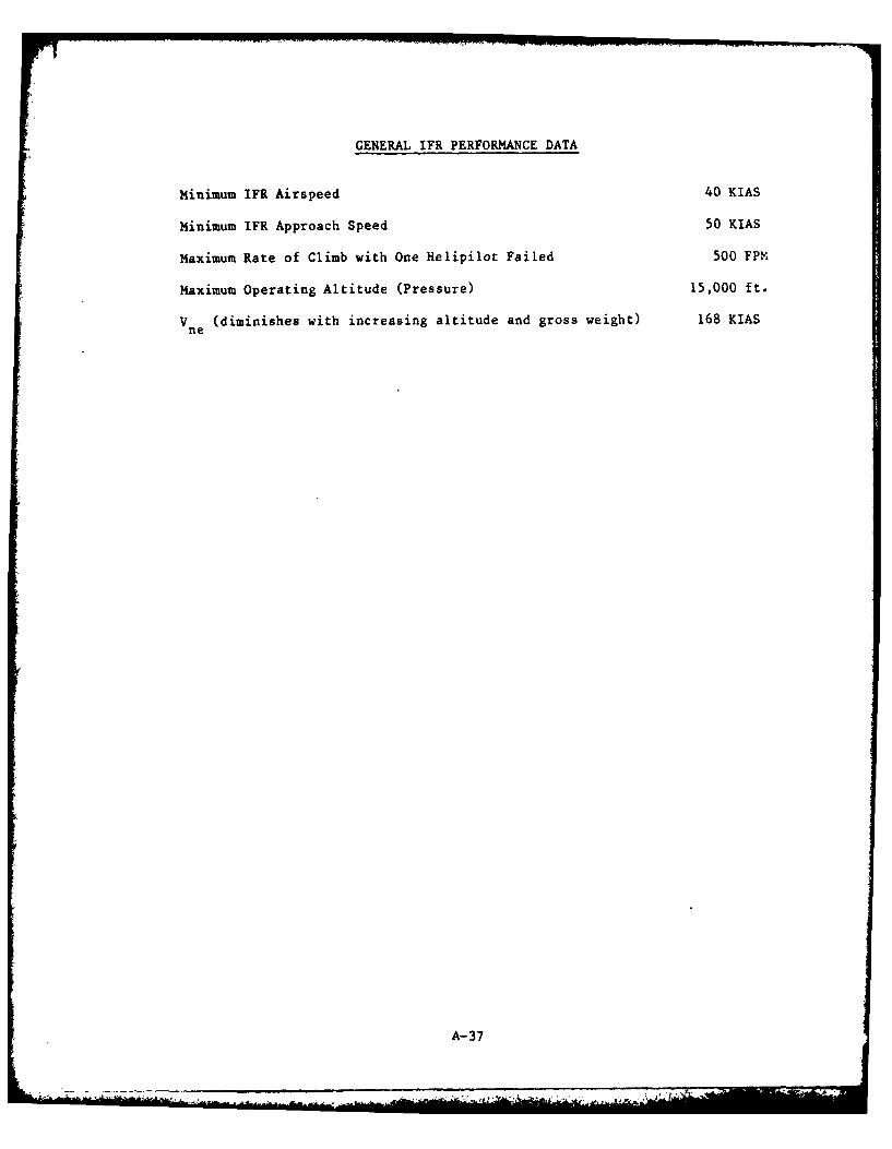
GENERAL IFR PERFORMANCE DATA
Minimum IFR Airspeed 40 KIAS
Minimum IFR Approach Speed 50 KIAS
Maximum Rate of Climb with One Helipilot Failed 500 FPM
Maximum Operating Altitude (Pressure) 15,000 ft.
Vne (diminishes with increasing altitude and gross weight) 168 KIAS
A-37
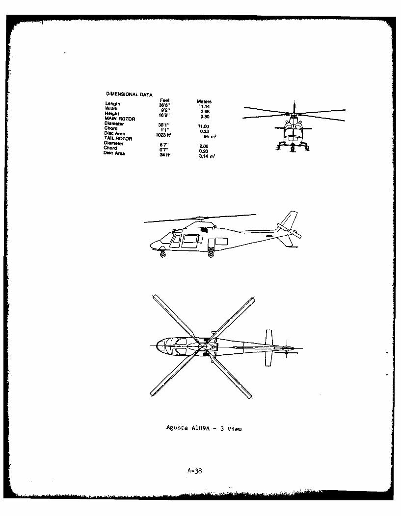
DIMENSIONAL DATAFeet MotersLength 36'8 11.14Width 97' 2.88Height 1019" 3&30MAIN ROTOR
Diameter 61"11.00Chord 0.33Disc Area103t95m
TAIL ROTOR 10396mDiameter 67' 2.00Chord 07" 0.20Disc Area 34Wf 3,14 ml
Agusta A109A -3 V!iew
A- 38
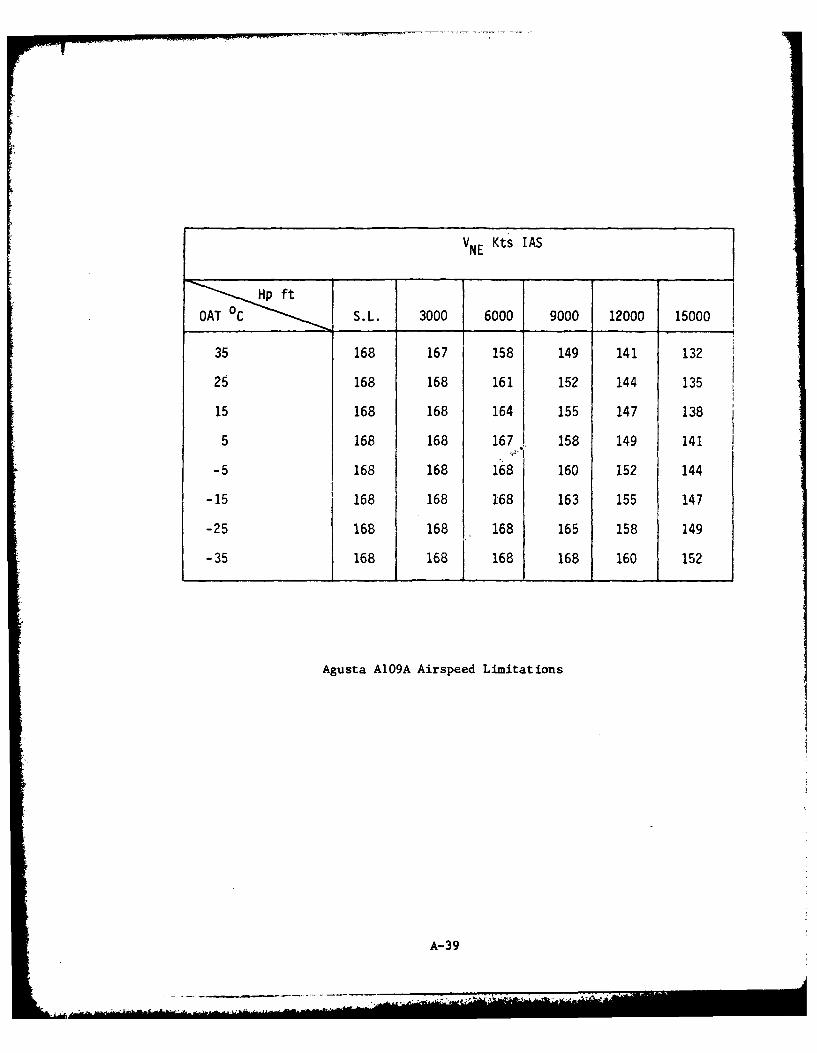
VNE Kts IAS
Hp ft
OAT 0C S.L. 3000 6000 9000 12000 15000
35 168 167 158 149 141 132
25 168 168 161 152 144 135
15 168 168 164 155 147 138
5 168 168 167 158 149 141
-5 168 168 168 160 152 144
-15 168 168 168 163 155 147
-25 168 168 168 165 158 149
-35 168 168 168 168 160 152
Agusta A1O9A Airspeed Limitations
A-39
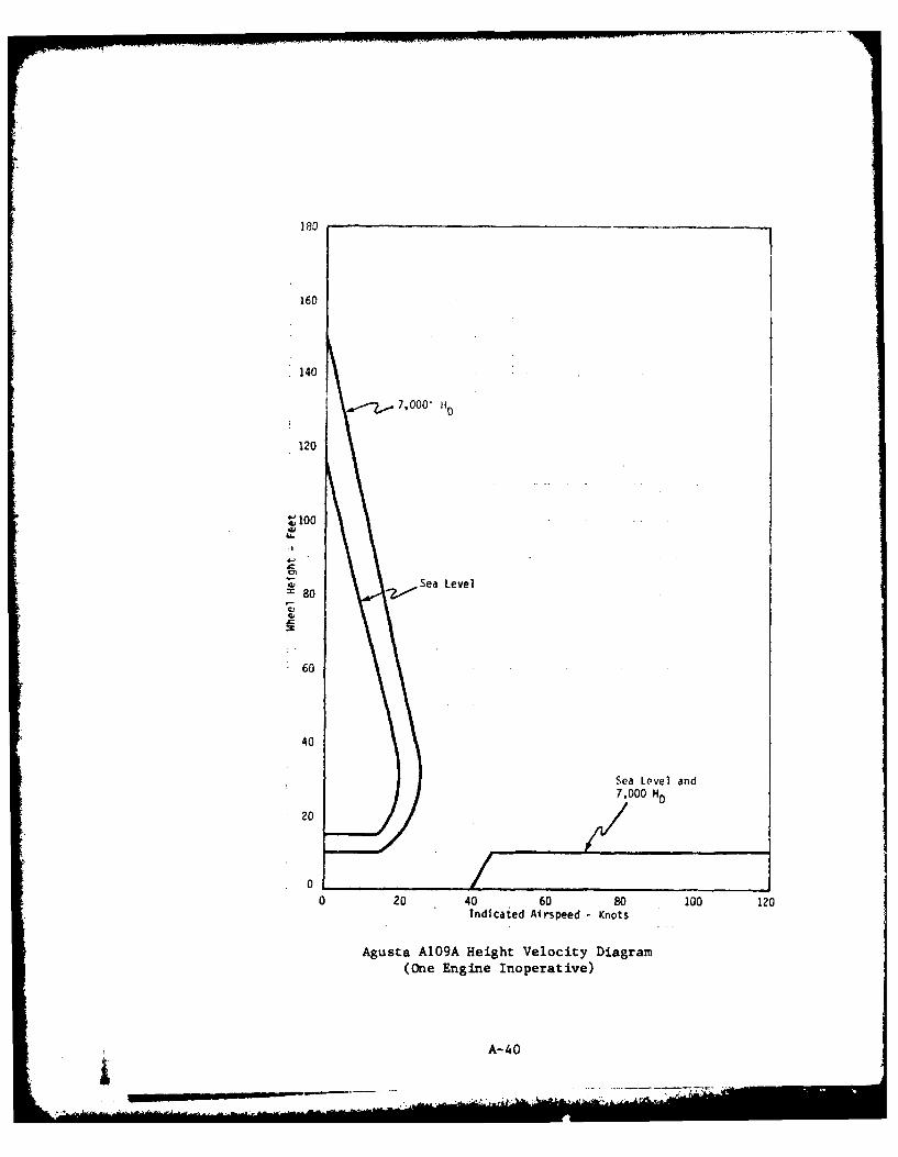
160
140
A7.7,000-
120
~100
4, Sea Level80 2
60
40
Sea Level and7,000 HO
20
0 ___0 20 40 60 80 100 120
Indicated Airspeed K Inots
Agusta A109A Height Velocity Diagram(One Engine Inoperative)
__ - A-40
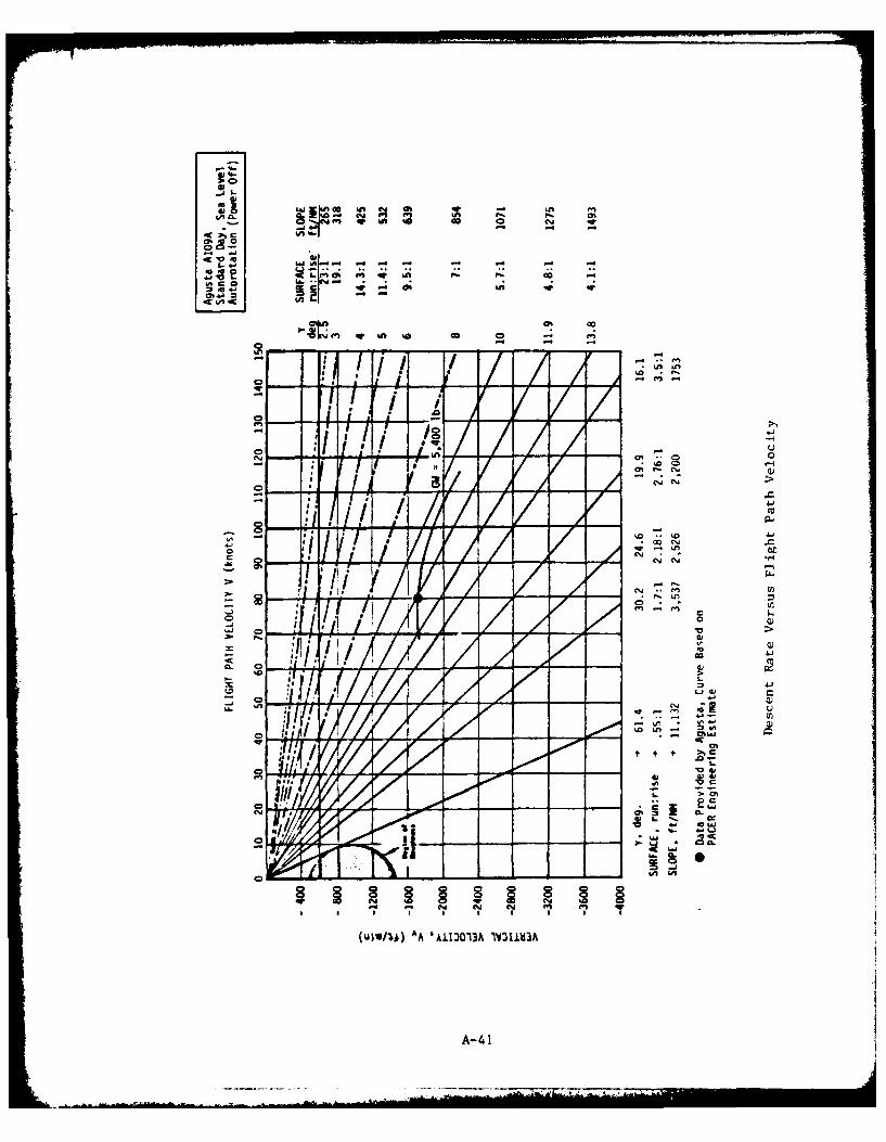
.0
-C 4
WZ~ IA A~ r 0Pa
0.~~P 4. mA * 0 0'a' s U
~ (A
I. " A %a o 40 - E1
*h' IVI YAI
e e l ..%0 be
C * 2 1- a.
7 !f CD
N 4.J
L.
C',
CL.'4A L
A-41-
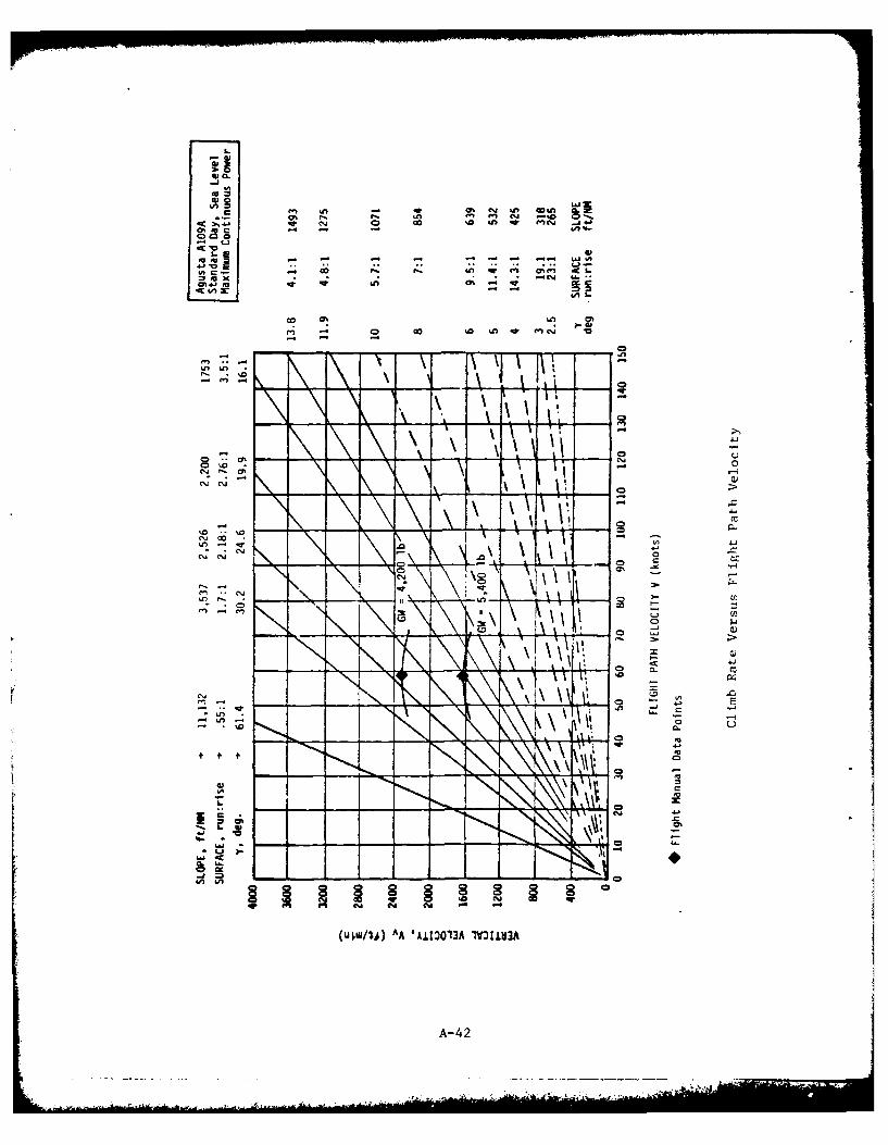
a
,
!k
0%j cy, Q),
u)- w 4
LE. 4 0
U, 11
~ 0% Ix
Ift-
C-44
.' ' . .... .. ..
Climb Rates
The following two figures present carpet plots of the best rate of
climb attainable at optimum climb speed and maximum continuous power for
a spectrum of aircraft weight and pressure altitude. One figure presents
data for standard day performance and the other, hot day performance when
temperatures are uniformly 20°C warmer than standard day at each altitude.
Two traces, ope labeled HOGE (hover out of ground effect) Boundary and
the other, HIGE (hover in ground effect) Boundary, cross the carpet plots
to identify those combinations of gross weight and altitude at which hover
capability becomes correspondingly limited. (Hover performance is based on
dual engine takeoff power vice maximum continuous power.)
A-43
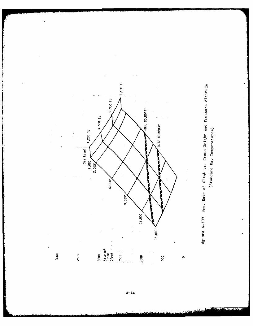
Ln,
0D
cc cI r
00
Ci~ '4n
C)- CD
A-4
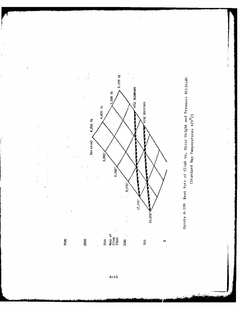
.0D
Q0X ~ c
.0 c~ '~C= Q +
4J
toco
cJH~
Ci.
C c
~V)Co
clii
C) C)C
0n -0
A-45o
I4- ... A
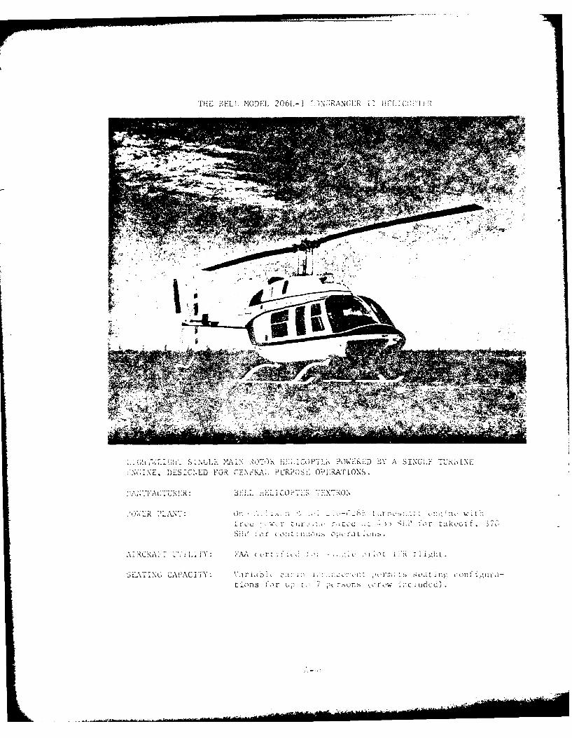
THE BEL.L MOD7l. 2061,-l ''NGEANCER 11 f, GUI (T'
(U7iG .S INGLE Wj ~"uR~jL~fj POVERED BY A SINGLE URININ(V;7NE, DESIGNED FOR r7\ i A il UR? SC OlPEiRAT !ONS
A\ T A> L-~,'iIIY: FAAo ..-,. .i. lot fi~t
BEL\i C, CAPACITY: ri, cjAA A : .dig.'l;u-t ions f or t,, 7 pt ronis ,CrCW ihC I LC~d)
INTRODUCTION
The Model 206L-l .LongRanger 1I is a 7-place lightweight helicoptermanufactured by Bell Helicopter Textron of Fert Worth, Texas. The heli-copter is designed for general purpose uses in the civil sector. It is astretched version of the Model 206 JetRanger series which includes thesLilitary light observation helicopter OH-58A Kiowa and the naval traininghelicopter TH-57A SeaRanger. The LongRanger II has been FAA certificatedfor single pilot IFR when equipped with functioning autopilot, force trimand normally required instruments, navigation and co-mmunication equipment.Flight into IMC is prohibited upon installation of certain auxiliary equip-ment packages such as the cargo hook, several landing gear and flotationoptions and other externally carried equipment not approved for IFR flight.
Standard configuration includes fixed skid landing gear, teeteringtwo-bladed main rotor and conventional two-bladed tail rotor. Weightedmain rotor blades ensure high rotational inertia for good auto rotationallanding capabilities and minimized gust sensitivity.
The Model 206L-I is powered by one Detroit Diesel Allison Model250-C28B turboahaft engine of the free power turbine type. The powerturbine section is two stage. Integral reduction gearing reduces outputshaft rpm to 6000. Maximu horsepower is 435 SEP. Continuous rating isfor 370 SUP.
A-47
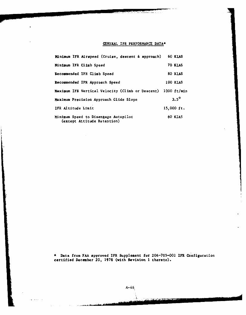
GENERAL1~ FR PERFORMANCE DATA*
MIinimumn IFR Airspeed (Cruise, descent & approach) 60 KIAS
Minimum IFR Climb Speed 70 KIAS
Recommended IFR Climb Speed 80 KIAS
Recommended IFR Approach Speed 100 KIAS
Maximum IFR Vertical Velocity (Climb or Descent) 1000 ft/mmn
Maximum Precision Approach Glide Slope 3.5 0
IFR Altitude Limit 15,000 ft.
Minimum Speed to Disengage Autopilot 60 KIAS
(except Attituxde Retention)
*Data from FAA approved IFR Supplement for 206-705-001 IFR Configurationcertified December 20, 1978 (with Revision 1 thereto).
A- 48
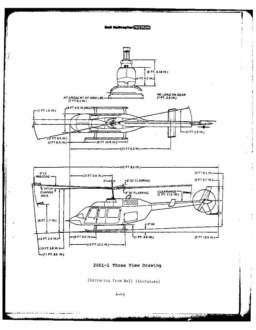
L L6 FT. 4. 18 1 N.)
(4FT4.01N.
NO LOAD ON GEARAT GROSS WT OF 4000 LBS. Fr. 2.0 IN.)
(7 FT 8.1 IN.)
.(4 FT 4.0 INJO(I FT 1.0 IN.)
07 FT 0.0 IN.)
F43 FT2.9 IN.)
(3 FT 8.0 IN.) fff#(9 FT 10.9 IN.)
23 FT 6.2 IN.)--r-
(42 FT 8.5 IN.)
2*15' (9 FT 6.1 IN.)PRECONE (10 FT 0.4 IN.) 5 8*30' FLAPPING (6 FT 5.7 IN.)
t PITC + CLEARANCE
ACCHANGE 8*30'FLAPPING (I FT. 113 IN.)
(6 F I N(6 FT 2.7 IN.) 2* 09'
.7
H
10 1 N. L (I FT. 3f0 IN.) (2 FT 10.5 IN.)TX T10 FT 2.4 IN.)
I(10 FT 3 .a IN+- (12 FT 10.2 INJ-
, I FT(I I FT. 8.3 IN.)
206L-1 Three View Drawing
(Extracted from Bell literature)
A-49
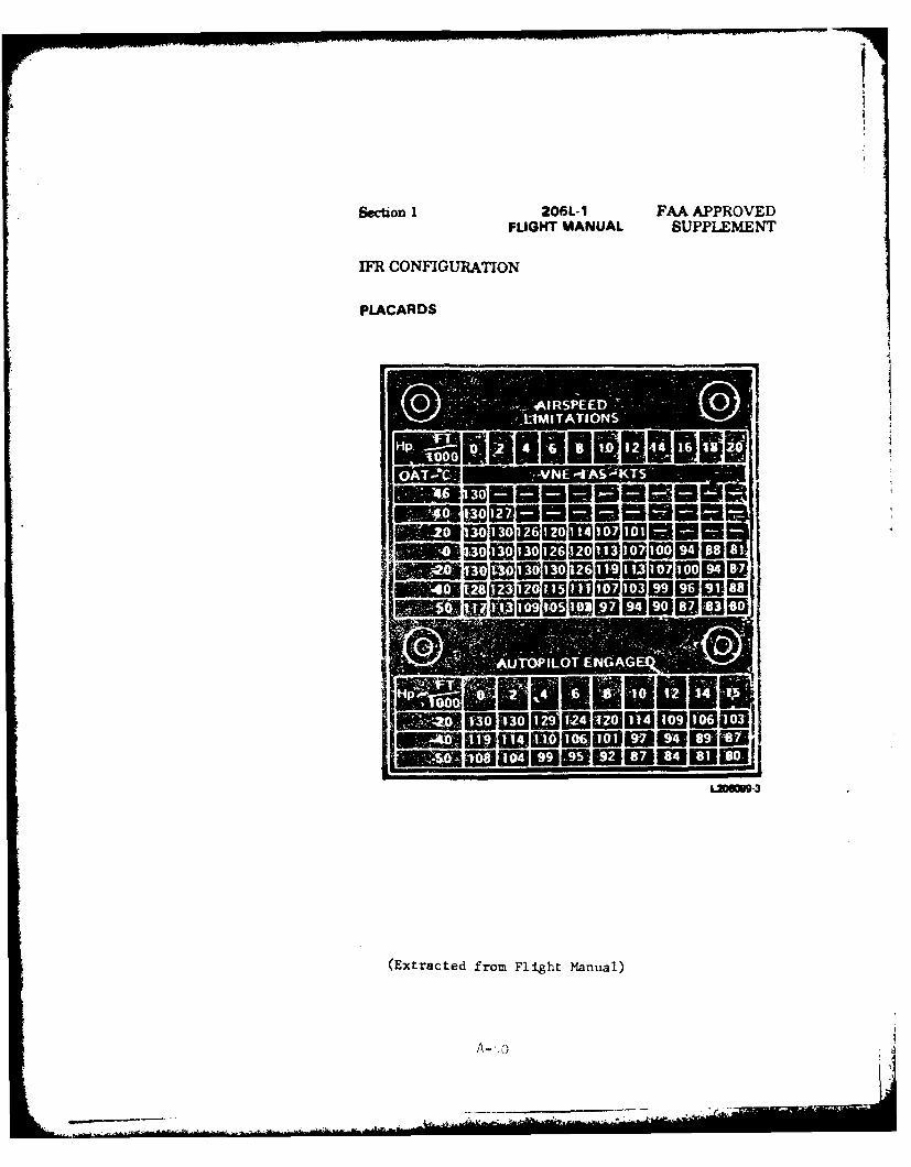
Section 1 206L-1 FAA APPROVEDFLIGHT MANUAL SUPPLEM4ENT
IFR CONFIGUR~ATION
PLACARDS
-_A-RSP-u
all 1202ow6www3
(Extracted from Flight Manual)
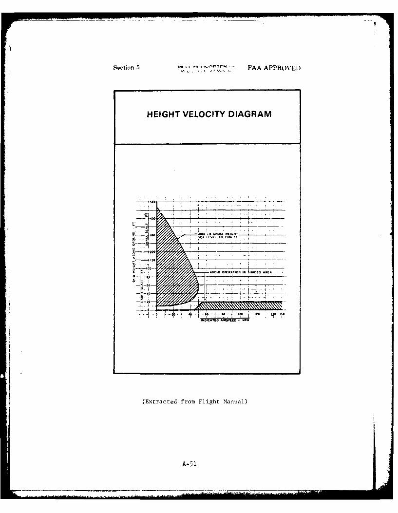
Section 5 :CCwl FAA APPROVED
H EIGHT VELOCITY DIAGRAM
- £00 LB GRO S$ C G
-to _"010IATE OA TON -0 MPHA DAE
(EtaceCfo FihtMnul
A-05
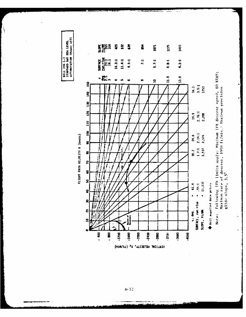
to -. - -p , ti - -
~~ff.
U~~l~~iP'~~ E' & -
r..X
A A/ L
CLC
tiE
A- 52~
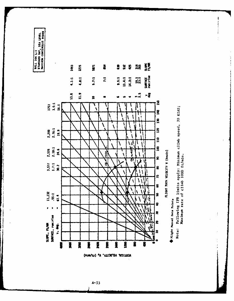
'0-b
4! ~~ V! It 0!mor4w -a
to #A I on 94
wt 6n- - - - W
* .
r L
a c
-4 X
I-All
MNVU NAA3 *I
Sn A-53
Climb Rates
The following two figures present carpet plots of the rate of climb
attainable at the recommended IFR climb speed (80 knots CAS) and maximum
continuous power for a spectrum of aircraft weights and pressure altitudes.
One figure presents data for standard day performance and the other hot dry
performance for temperatures uniformly 200C warmer than standard day at
each altitude.
Two traces, one labelled HOGE (hover out of ground effect) Boundary
and the other HIGE (hover in ground effect) Boundary cross the carpet plots
to identify those combinations of altitude and gross weight at which hover
capability becomes correspondingly limited. (Hover performance is based
on takeoff power vice maximum continuous power used during climb.)
It can be seen that the IFR climb capability of the Bell 206L-I does
not satisfy the rule of thumb for climb gradient since combinations of
gross weight and altitude exist on the hot day plot for which HOGE is
possible but rate of climb is insufficient to ensure a 20:1 climb gradient
(approximately 100 fpm for each 20 kts of airspeed). Consequently, pilots
of this aircraft must also compute expected climb performance and its
relationship to a 20:1 missed approach gradient to ensure that an adequate
climb profile can be sustained if a missed approach should become necessarv.
Computation of expected hover performance does not alone provide such
assurance as would be the case if the best rate of climb airspeed were
within the envelope of acceptable IFR climb speedb.
A-54
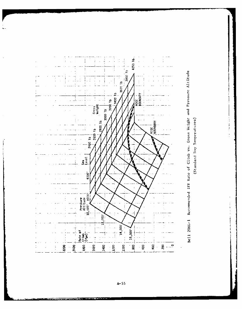
* C.,
. C0
CC
Az, m
cc. CD
m> 0
CDCC
A-. CC
ov- 4o
Cb . 4= 0&fql em.
A- 55
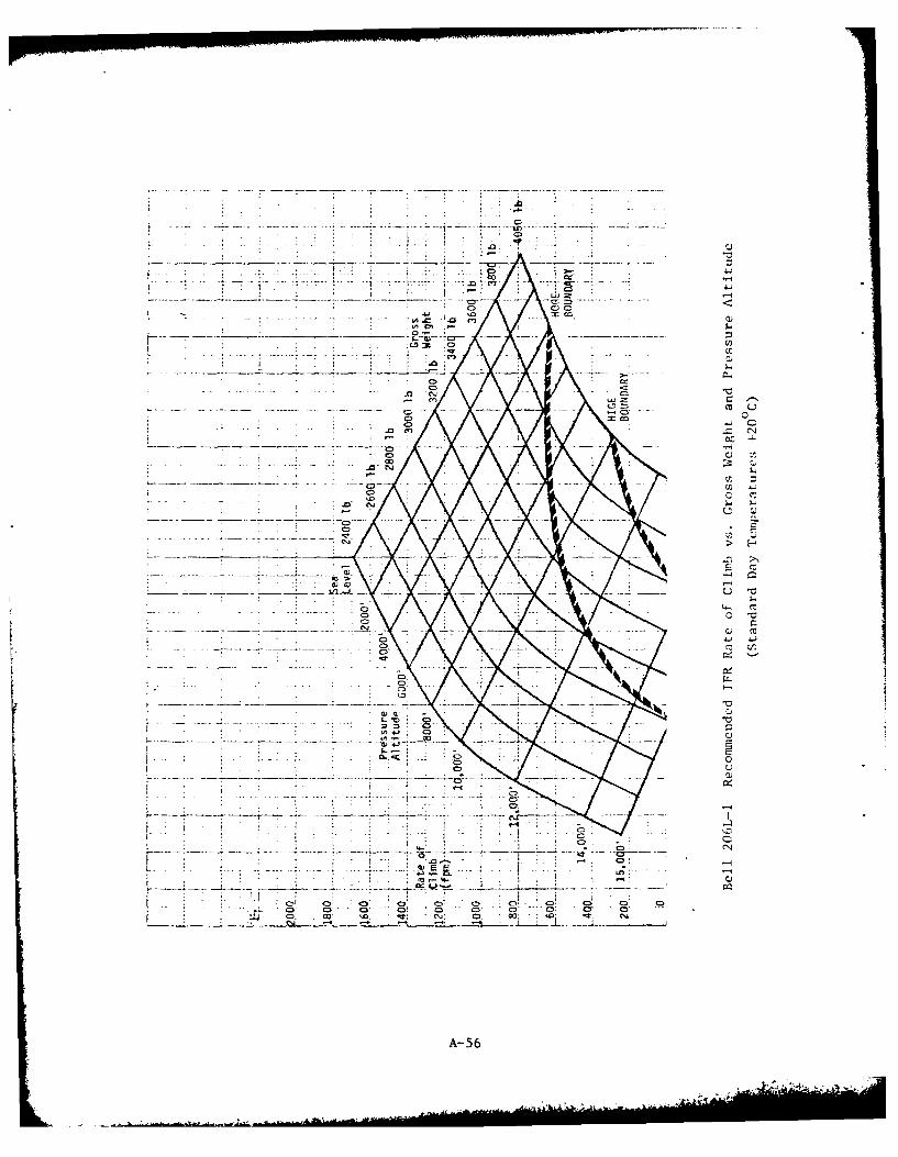
C> -
ci:
- -~~~0I- - - -- ------ C: .
C>o cm
-C~
CC
*~0 - 0
A- -L
41.4
455
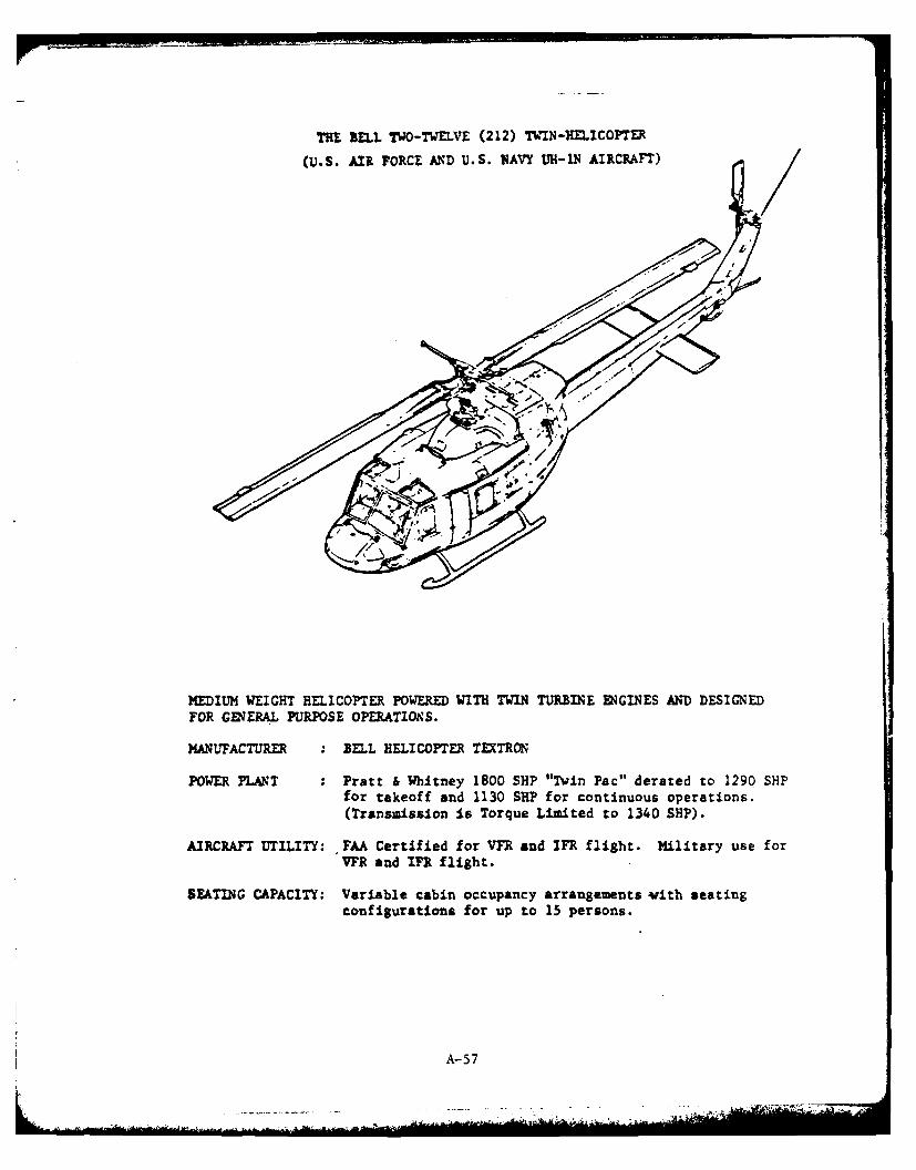
THE BELL TWO-TWELVE (212) TWIN-HELICOPTER
(U.S. AIR FORCE AND U.S. NAVY UH-IN AIRCRAFT)
MEDIUM WEIGHT HELICOPTER POWERED WITH TWIN TURBINE ENGINES AND' DESIGNEDFOR GENERAL PURPOSE OPERATION~S.
MANUFACTURER :BELL HELICOPTER TEXTRON
POWER PLANT : Pratt & Whitney 1800 SHP "Twin Pac" derated to 1290 SHIPfor takeoff and 1130 SHP for continuous operations.(Transmission is Torque Limited to 1340 SHP).
AIRCRAFT UTILITY: FAA Certified for VFR and IFR flight. Military use forVYR and IFR flight.
SEATING CAPACITY: Variable cabin occupancy arrangements with seatingconfigurations for up to 15 persons.
A- 57
INTRODUCTION
The Two-Twelve Twin is a 15-place medium weight helicopter manufacturedby the Bell lelicopter Textron Company. The helicopter is designed for gen-eral purpose operations in both the civil sector (Bell 212) and the military(U.S. Alr Force and U.S. Navy, UH-IN). Both the civil and military versionsare capable of In flight. The civil version has been FAA approved for IFRflight in two versions:
o Be11-212; FAA certified for If flight with a two-pilot aircrewvith the Bell inK system installed. The system contains singlestring, SIMPLEX, stability and control augmentation system, attituderetention autopilot, mechanical control-mixing unit, associatedinstruments, avionics, and controls.
" Sperry/Bell-212; FAA certified for in7 flight with a one-pilotaircrew with the Sperry IFR system installed. The system containsredundant actuator strings, DUPLEX, stability and control augmen-tation systems, attitude-hold systems, associated instruments,avionics, and controls.
The military version, UH-IN, is capable of operation from prepared orunprepared takeoff and landing areas, under visual (VFR) or instrumentconditions (In), day or night.
The Two-Twelve is powered by a 1800 SEP Pratt & Whitney "Twin Pac"turboshaft engine system (civil, PT6T-3 or military T400-CP-400). Theengine consists of two independent power sections driving into a combininggearbox. The "TWin Pac" is derated to 1290 SEP (for Takeoff Power) and1130 SEP (for Maximum continuous operation). A torque Limiting systemprevents power in excess of 1340 SUP from being applied to the trans-mision in the derated installation, For single engine operation, 900 SHPis available for 30 minutes and 800 SEP for continuous use. Full use wasmade of performance data on the Bell-212 helicopter as obtained fromreports, research data, k torcraft Flight Manuals, RFM, (in7 Book and VnRBook) as well as other supporting information and data on takeoff, descent,and climb performance as shown in material such as military flight hand-books and NATOPS Flight Manuals. This information was utilized to preparethe general performance data and to construct the PERFORHMMNCE AND MAKEUVEFCIARTS AND ENVELOPES shown on the following pages.
A-58
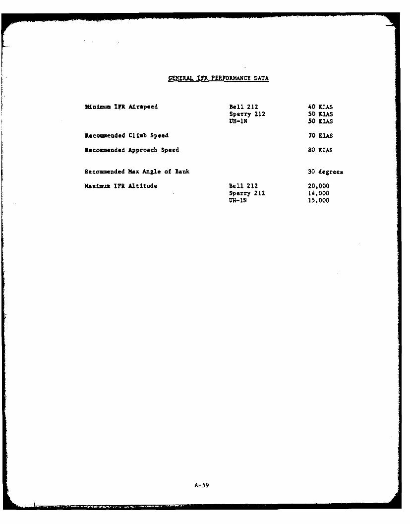
GENERAL InR PERFORMANCE DATA
Minim-a IFR Airspeed Bell 212 40 KIASSperry 212 50 MISUm-IN 30 [lAS
Recomended Climb Speed 70 [LAS
Recommended Approach Speed 80 [lAS
Recommended Max Angle of Bank 30 degrees
Maximum IFR Altitude Bell 212 20,000Sperry 212 14,000tm-IN 15,000
A- 59
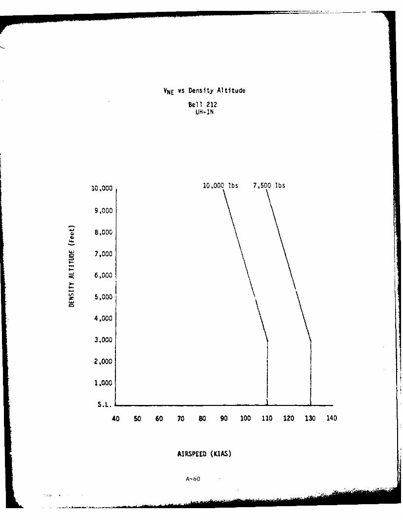
VNE vs Density Altitude
Bell 212
UH-1N
10,000 10,000 lbs 7,500 lbs
9,000
8,000
7,000
6,000
5,000
4,000
3,000
S.1.
40 50 60 70 80 90 100 110 120 130 140
AIRSPEED (KIAS)
A-60

700 - - - - - - - - - - - - - - - - - -
-~ -4-Soo
300
200 I
100
00 20. 40 -0IO 0
ESTIMATE DATA
REFRECE .AOP FLIGH W A FOIH (el22NAAI 1-10C-1d ted MRC-177
0Wh 1*c* igo orda ~n aueEE
0 20 40 0 AO 60
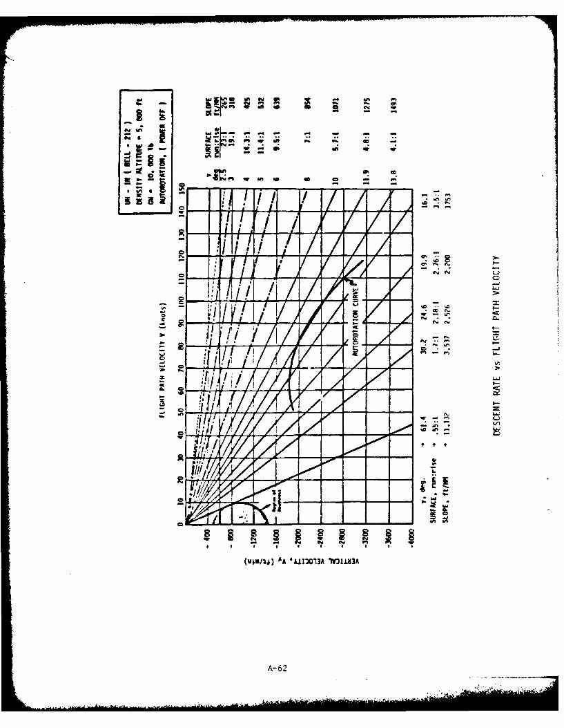
./ A /I-
7" N *
C ~C,
* ~//I I.- A x -o
9N -
666
A-62
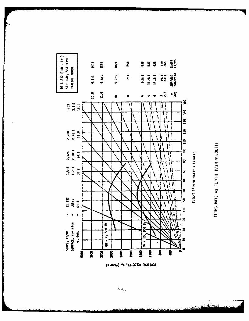
m A 14 2110
0- fit
U,* , ~ - q
-d -
~~L10
*AU03 10 PIN
-A-6
Climb Rates
The following two figures present carpet plots of the best rate of
climb attainable at optimum climb speed and maximum continuous power for
a spectrum of aircraft weight and pressure altitude. One figure presents
data for standard day performance and the other, hot day performance when0temperatures are uniformly 20 C warmer than standard day at each altitude.
Two traces, one labeled HOGE (hover out of ground effect) Boundary and
the other, HIGE (hover in ground effect) Boundary, cross the carpet plots
to identify those combinations of gross weight and altitude at which hover
capability becomes correspondingly limited. (Hover performance is based on
dual engine takeoff power vice maximum continuous power.)
A-64
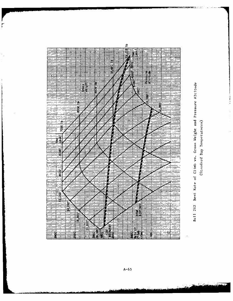
777:~ .61
=1__ _ Er
A- 65
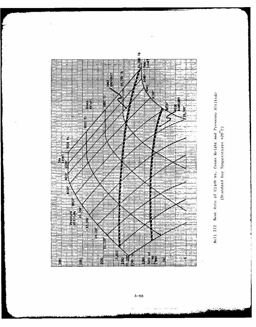
.0r
__cc +
InE~
c. cz
ocir
A- 66
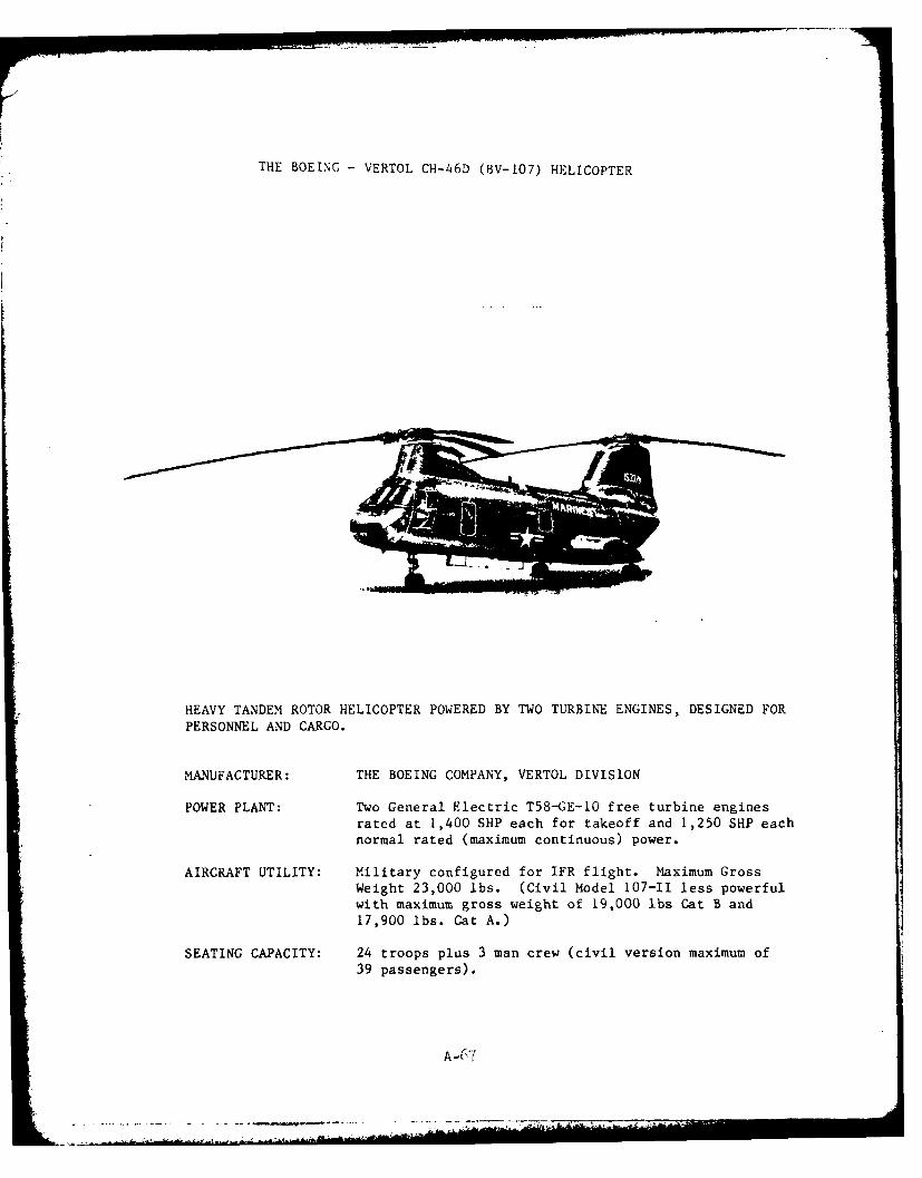
THE BOEING - VERTOL CH-46D (BV-107) HELICOPTER
HEAVY TANDEM ROTOR HELICOPTER POWERED BY TWO TURBINE ENGINES, DESIGNED FOR
PERSONNEL AND CARGO.
MANUFACTURER: THE BOEING COMPANY, VERTOL DIVISION
POWER PLANT: Two General Electric T58-GE-1O free turbine enginesrated at 1,400 SHP each for takeoff and 1,250 SHP each
normal rated (maximum continuous) power.
AIRCRAFT UTILITY: Military configured for IFR flight. Maximum GrossWeight 23,000 lbs. (Civil Model 107-11 less powerful
with maximum gross weight of 19,000 lbs Cat B and
17,900 lbs. Cat A.)
SEATING CAPACITY: 24 troops plus 3 man crew (civil version maximum of
39 passengers).
A-67
k ..... A....
-2 - --- - -
INTRODUCTION
The CH-46D is utilized by the military for two distinct missions. TheU.S. Marines use it primarily for troop movement as an assault transportwith a secondary role of resupply carrying cargo internally or externally.The U.S. Navy uses it primarily for external lift of supplies betweensupport and combatant ships. Cargo hook capacity is 10,000 lbs. (Aslightly less powerful civil version, the BV 107 is currently used princi-pally in logging operations.) Both military and civil operations require aminimum crew consisting of pilot and copilot.
The CH-46D has fixed tricycle landing gear for land operations and anemergency water landing capability with integral flotation. The rotorsystem consists of two three-bladed, fully-articulated rotors of equaldiameter arranged in an overlapping tandem configuration. The CH-46D ispowered by two T58-CE-10 turboshaft engines employing a single stage freepower turbine. These are rated at 1,400 SHP (military power) for 30
minutes or 1,250 SHP (normal power) continuously. (The similar CT58-110-1engines of the civil version are rated at 1,250 SHP takeoff limit for 5minutes and at 1,050 SHP for maximum continuous operation. Emergencyratings with one engine inoperative permit 2 1/2 minutes operation at 1,350SHP or 30 minutes operation at 1,250 SHP.) Both engines drive a transmis-sion mix box located just forward of the aft transmission. The mix box
combines the inputs of both engines to drive the aft transmission directlyand the forward transmission by means of a synchronizing drive shaft.
The performance data shown herein have been extracted from the mili-tary NATOPS (Naval Air Training and Operating Procedures) Flight Manual forCH-46D/F and Lh-46D aircraft.
A-68

GENERAL IFR PERFORMANCE DATA
Minimum IFR Airspeed 40 KIAS
Recommended Climb Speed 70 KIAS
Maximum Bank Angle for Climbing Turn 200
VNE 145 K1AS*
Recommended Approach Airspeed Cruising Speed**
* 145 KIAS limit applies Lo aircraft equipped with an integral system for
determining rotor blade spar integrity. H-46 aircraft not so equippedare limited to not more than 125 KIAS.
** Best range cruise speeds are typically of the order of 100-130 KIAS
depending in weight and altitude with the higher speeds associated withlower altitudes. These correspond to 110-130 KTS TAS for standard dayconditions. The military recommendation is based on minimization ofcross wind effects in approach through use of maximum practical airspeed.
A-69
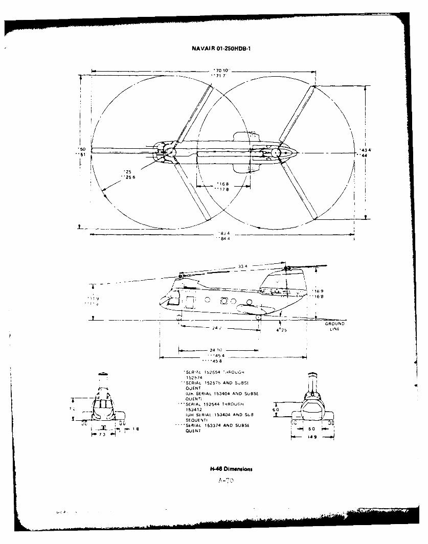
PJAVAIR 01-2501HDB-l
*7010-
50
84 4
- 33 4
/1 --
I ~ I GROUND
24 ** 4'25 LINE
..-.. 458-
152574
SERIAL 152575 AND SUBS[OUENT
A (UH SERIAL 153404 AND SUBSE -
QuENT)* SERIAL 152544 THROUGH
7 1 53412 60
IUI4 SERIAL 153404 AND SUB _ 4
U EN TSERIAL 153374 AND SUBSE ~6 4
14-46 Dimensions
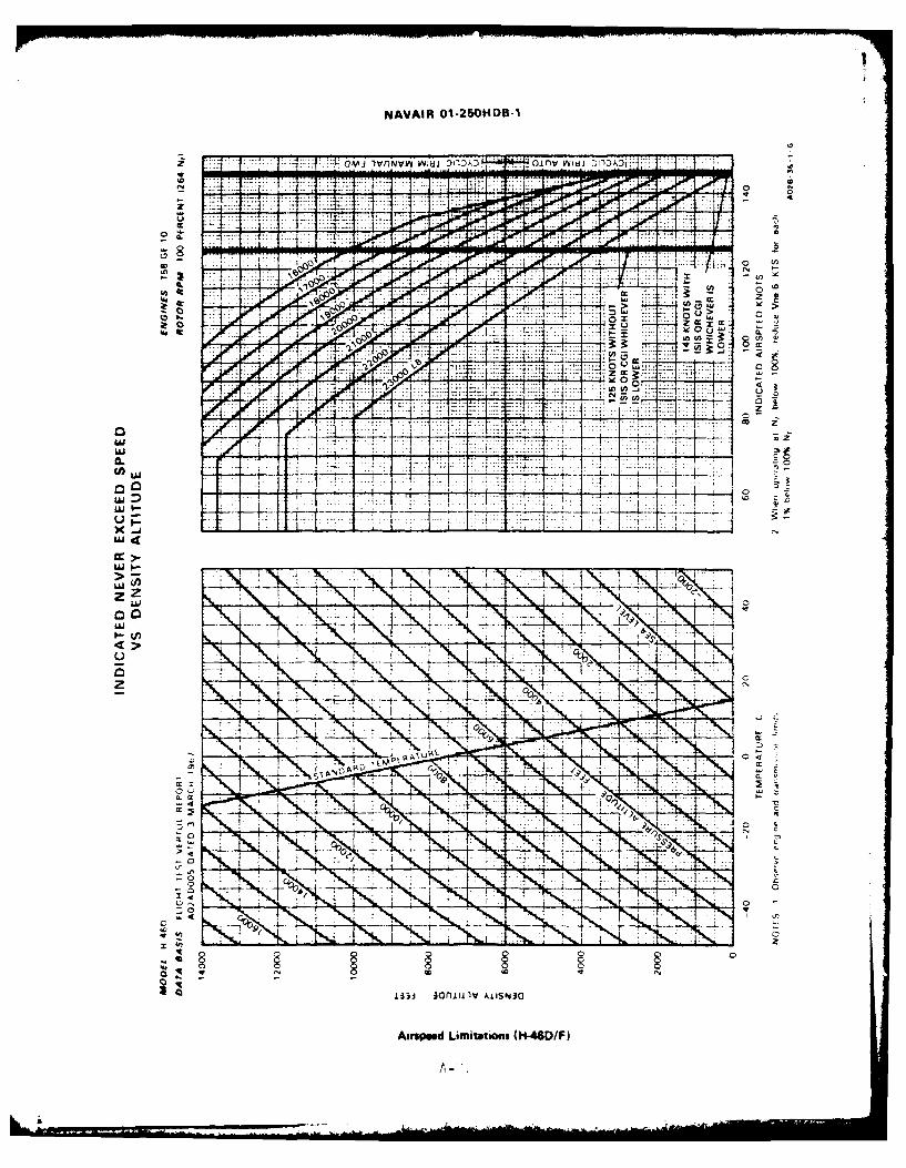
NAVAIR 01-250HDB-l
.. . . . ...
CL 7
aMiM-1 - -7
000
-or
00
0 ...... ...
i33~~Al iulIW iS3
Aiuweed~. L..ttm n ..-.....
LII-
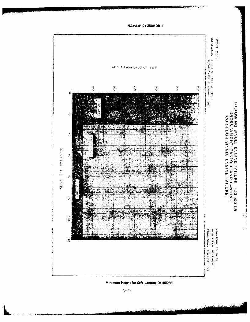
NAVAIR 01-25ON4DB-1
HEIGHIT ABOVE GRO)UNf FFE7
I-n
C~ u 0C
CC
-n0n
7 T'-
~>
-4; 7:,11 -
7t 00rn
M7rmu >egtfrSf adn 14DF
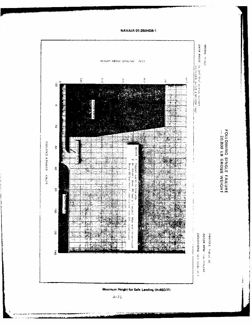
NAVAIR 01-25OHDB-1
HEIGEIr ABOVE GHOUNO FEET
nC
M x
00
0
L2
7:o cr
C
G_ _ _ _ __4
0
ZC
Minimum Height tor Safe Landing (H-460/F)
A- 7

nC
3-7,-
rtzl
I awn '
77 uN)
r.
1
oolkfl
4 KI'Wr

0 r4 C
- -
(~0
z 40z
C, Ln 'a o o 5
o ' ,
-t 0
In, CD 0
'a
(U.LW/11)~~I- A 44*D1AIV~U
o ' "4A-75
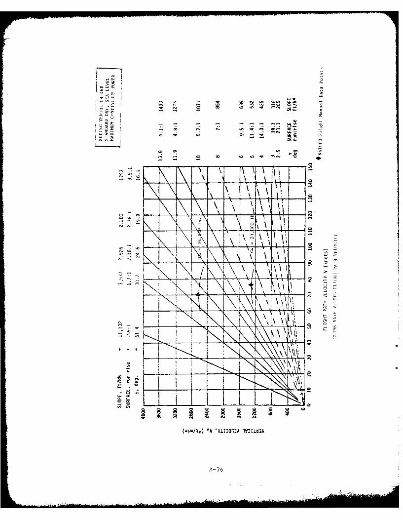
- 0% 61 In, C-
cl 00 -W c'
z Cc - on e 0I
00 01 LI R r
- -
K
0~ 0~ T\' 'CD
A-70
Climb Rates
The following two figures present carpet plots of the best rate of
climb attainable at optimum climb speed and maximum continuous power for
a spectrum of aircraft weight and pressure altitude. One figure presents
data for standard day performance and the other, hot day performance when
temperatures are uniformly 200C warmer than standard day at each altitude.
Two traces, one labeled HOGE (hover out of ground effect) Boundary and
the other, HIGE (hover in ground effect) Boundary, cross the carpet plots
to identify those combinations of gross weight and altitude at which hover
capability becomes correspondingly limited. (Hover performance is based on
dual engine takeoff power vice maximum continuous power.)
A-77
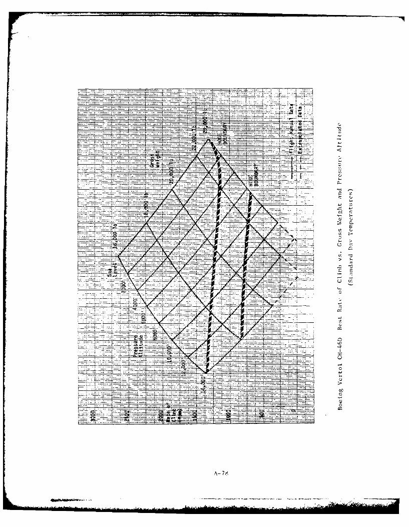
_________~~ ----- - - ----- - . .
4-J
A-7-

-yc-
A- 79
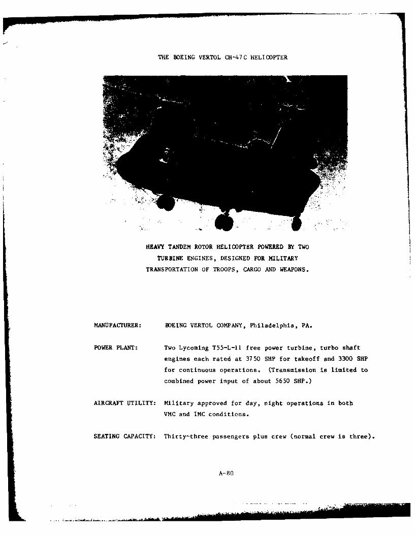
THE BOEING VERTOL CH-47C HELICOPTER
HEAVY TANDEM ROTOR HELICOPTER POWERED BY TWO
TURBINE ENGINES, DESIGNED FOR MILITARY
TRANSPORTATION OF TROOPS, CARGO AND WEAPONS.
MANUFACTURER: BOEING VERTOL COMPANY, Philadelphia, PA.
POWER PLANT: Two Lycoming T55-L-I1 free power turbine, turbo shaft
engines each rated at 3750 SHP for takeoff and 3300 SHP
for continuous operations. (Transmission is limited to
combined power input of about 5650 SHP.)
AIRCRAFT UTILITY: Military approved for day, night operations in both
VMC and IMC conditions.
SEATING CAPACITY: Thirty-three passengers plus crew (normal crew is three).
A-80
INTRODUCTION
The CH-47C Chinook helicopter is a heavy military transport helicopter
used for movement of troops, cargo and weapons. It is employed by the U.S.
Army and derivative versions are used in the armed forces of many foreign
nations. No civil versions are currently certificated, but development of
a civil derivative is underway for deliveries commencing in 1981. The
Chinook is manufactured by the Boeing Vertol Company in Philadelphia,
Pennsylvania, and by Cost-ruzioni Aeronautiche Giovanni Agusta under license
in Italy.
The CH-47C is a tandem rotor, twin engine helicopter with a large cabin
volume and rear loading ramp. Landing gear is not retractable. It consists
of two fixed forward tandem mounts and two full swiveling single aft
mounts, one of which is steerable. The two main rotors each consist of
three blades and counterrotate to offset torque effects.
The aircraft reported on is powered by two Lycoming T55-L-lI engines
which develop 3750 SHP for takeoff (10 min rating), and sustain the 3750
SHP at military rating (30 min). Maximum continuous power is 3300 SHP.
Transmission torque limits are reached at about 5650 SHP for dual engine
operations and at 3625 SHP for single engine operations.
Performance data presented herein have been extracted from the U. S.
Army CH-47C Operators Manual, TM55-1520-227-I0-2 (dated 23 August 1971 with
Changes I and 2 incorporated).
A-81
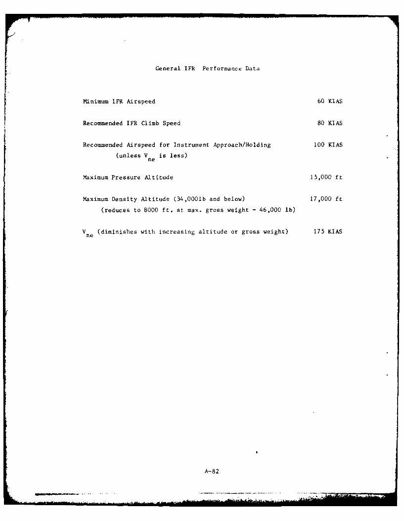
General IFR Performance Data
Minimum IFR Airspeed 60 KIAS
Recommended IFR Climb Speed 80 KIAS
Recommended Airspeed for Instrument Approach/Holding 100 KIAS
(unless V is less)ne
Maximum Pressure Altitude 15,000 ft
Maximum Density Altitude (34,0001b and below) 17,000 ft
(reduces to 8000 ft. at max. gross weight - 46,000 lb)
V (diminishes with increasing altitude or gross weight) 175 KIASne
A- 82
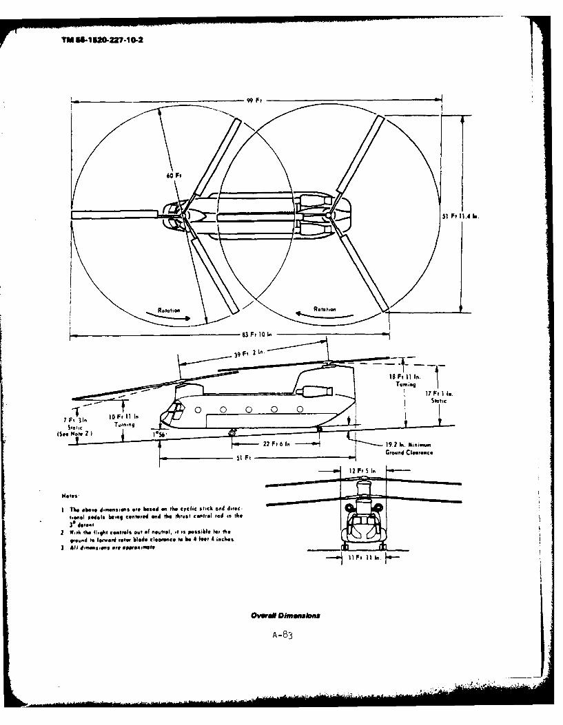
TIN 55-tU*-227-1O.2
83 det10nI
Ovw~17 Ftm I In.
Stati
10~. Fil I
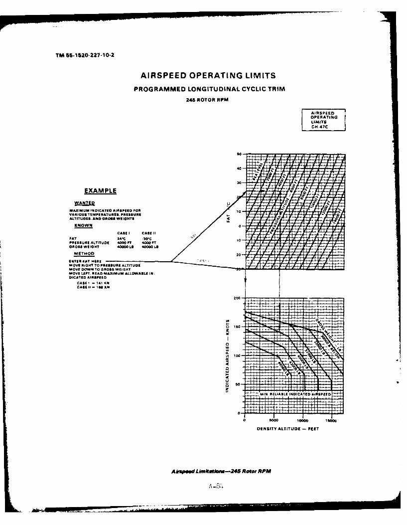
TM 55-1520-227-10-2
AIRSPEED OPERATING LIMITS
PROGRAMMED LONGITUDINAL CYCLIC TRIM
245 ROTOR RPM
OPER ATI NGU M ITSCH-47C j
EXAMPLE
WANT!ED
MAXIMUM INDICATED AIRSPEED FOR 1VARIOUS TEMPERATURES, PRESSUREALTITUDE$. AND GROSS WEIGHTS -
KNOWN 0
CASE I CASE 11PAT 24M *30*CpRESSURE ALTITUDE 4000 FT 4000OFTGROSSwEIOHT 40000 LB 40000 Le
METHOD.2
ENTER FAT HEREMOVE RIGHT To PRESSURE ALTITUDEiMOVE DOWN TOGROSS WEIGHTMOVE LitFT R EAD MAXIMUM ALLOWABLE IN-DICATED AIRSPEEDo
CASE' - 41 1,1,CAS I SO65E
I T I
0150-Z
MIN, REI.IAEI.E INDICATED AIRSPEED
0-
0 S000 Io000 law0
DENSITY ALTITUDE - FEET
Aksped Lkimtat~ia-245 Reoo RPM#
A -84+
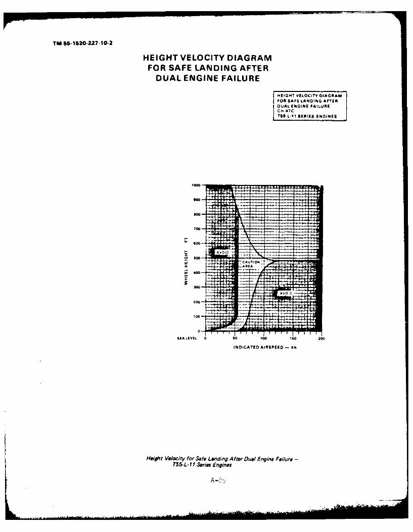
TM 55-1520-227-10-2
HEIGHT VELOCITY DIAGRAMFOR SAFE LANDING AFTER
DUAL ENGINE FAILURE
HEIGHT VELOCITY DIAGRAMFOR SAF E LANdDINIG AFTE RDUAL ENGINiE FAILURECm 47CT56 L-11 SERIES ENGINES
T
SE 1EVL0 6 00 0 0
IICTE ISPE
lfigtVeoit orSfeLndngAte ua ngn Fiur
T5-- 1SrisEnie
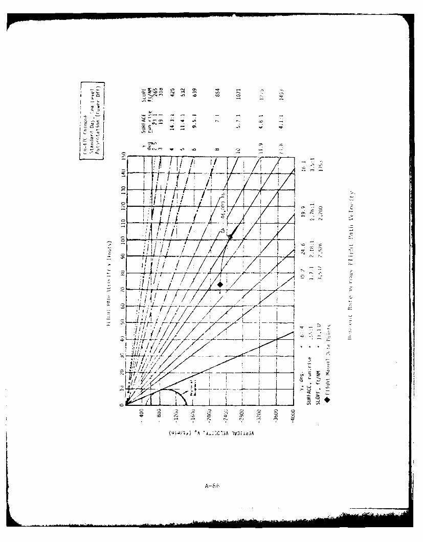
10 II
3' A
CDC
LID
- 65.,.~
o ow
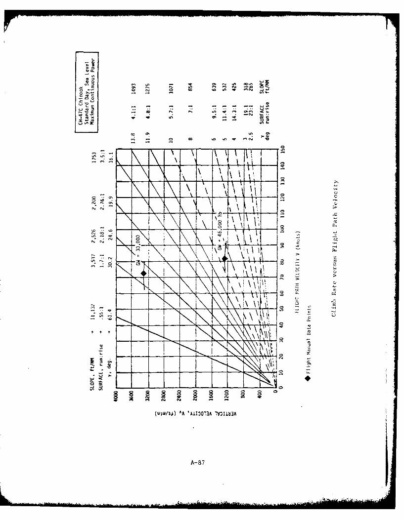
-4,
00 10 In, -Wn V
0 7: ON ~ 4 (CJ .J
CD 0~ci,-, cl
C14- - -
- CDl~ ~ 0(
*~ ~ Ai CD -
~~ \l N%-
0-. 2-
C4 r SO
qr en C-4 ~j N
(oW "A~.2 'A1303 _V113
A-87 Li
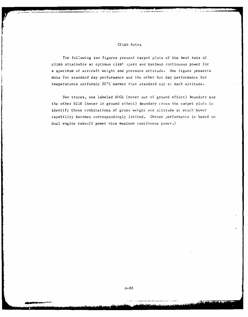
Climb Rates
The following two figures present carpet plots of the best rate of
climb attainable at optimum climb speed and maximum continuous power for
a spectrum of aircraft weight and pressure attitude. One figure presents
data for standard day performance and the other hot day performance for
temperatures uniformly 20C warmer than standard day a: each altitude.
Two traces, one labeled HOGE (hover out of ground effect) Boundary and
the other HIGE (hover in ground effect) Boundary cross the carpet plots to
identify those combinations of gross weight and altitude at which hover
capability becomes correspondingly limited. (hover performance is based on
dual engine takeoff power vice maximum continuous power.)
A-88
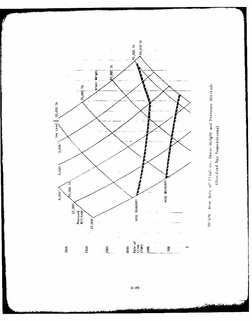
C> 1
0-0c
C)I-
-E C
CC 0
C),
CD CC
CDC
CiCON9
c>C
03 a 00 - 0)m 4-
-- C
A-89
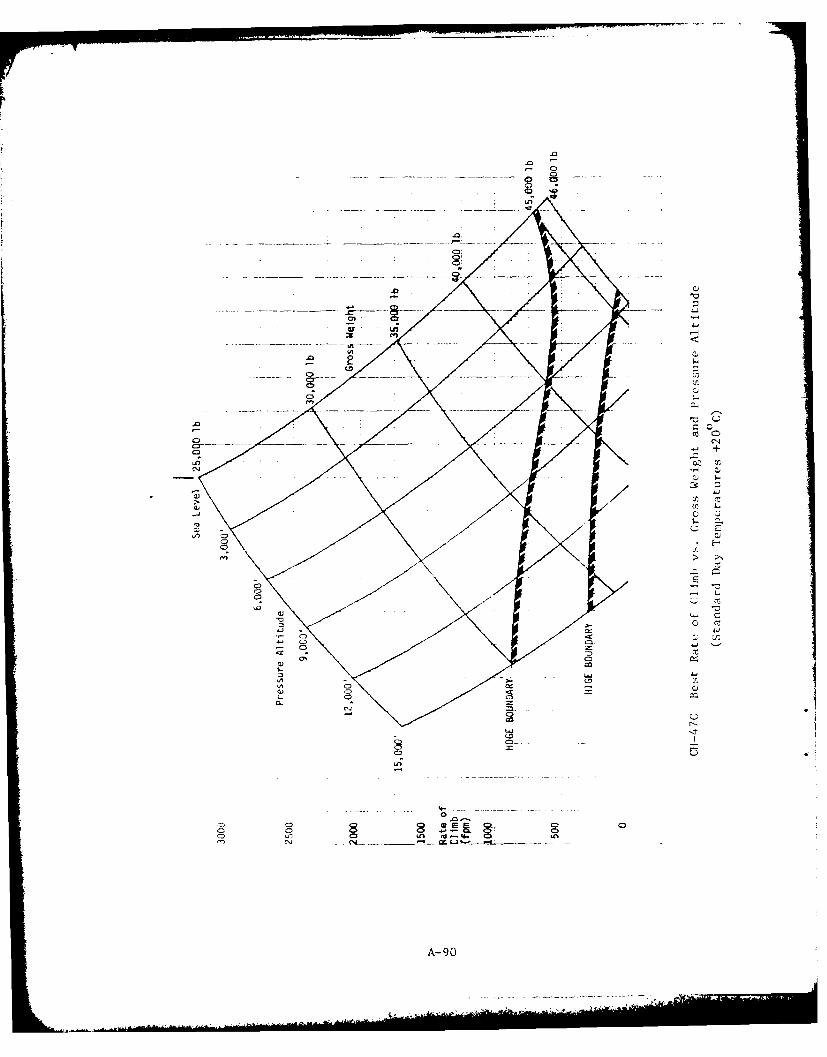
0
C-
tr0
C(C
C3C-
CC C-D
CD-
C! C5
41 C.
A-90
------ ------
INTRODUCTION
The S-61N helicopter is designed to transport cargo and passengersboth over land and water. .Configuration is a single rotary wing, twinturbine powered helicopter with emergency amphibious landing capability.The military version, SH-3 and EH-3 series, comes in several config-urations with mission areas in utility, search and rescue, and anti-submarine warfare.
Both the civil and military versions are fully IFR capable withthe exception of flying in known icing conditions. All versions havea three directional automatic flight control system (AFCS) and abarometric altitude hold capability. The AFCS is required for flightin instrument conditions.
The S-61N and H-3 are powered by twin turbine engines rated at1400 SEP each with 1250 SEP for continuous operations. For singleengine operations 1400 SEP is available for 30 minutes. Full use wasmade of performance data as obtained from reports, research data,Rotocraft Flight Manuals, and military flight handbooks. This infor-mation was utilized to prepare the general performance data and toconstruct the Performance and Maneuver Charts shown on the followingpages.
A-92
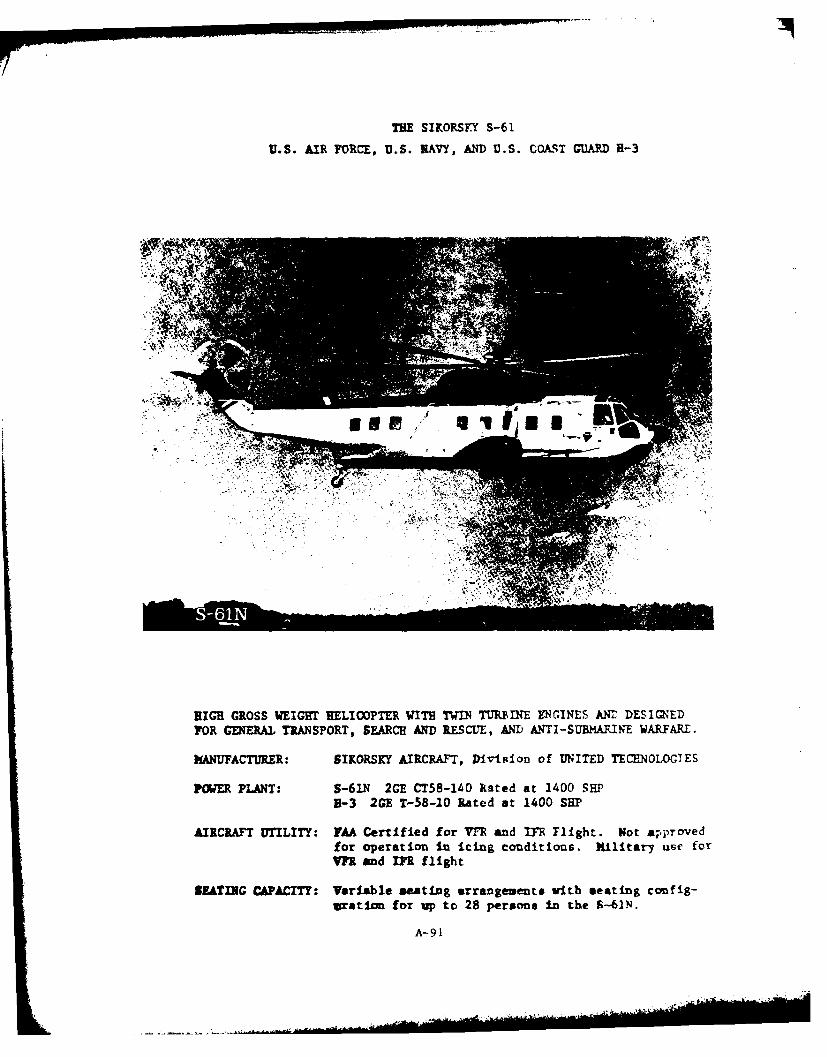
THE SIKORSY S-61
U.S. AIR FORCE, U.S. NAVY, AND U.S. COAST GUARD H-3
RIGH GROSS WEIGHT BELICOPTER WITH TWIN3 TURBIN E ENGINES AN-L DESIMED
FOR GENERAL TRANSPORT, SEARCH AND RESCUTE, AND ANTI SURMARINE WARFARE.
MANUFACTURER: SIKORSKY AIRCRAFT, Division of UNITED TECHNOLOGIES
PWER PLANT: S-61N 2GE CT58-140 Rated at 1400 SHP1-3 2GE T-58-10 Rated at 1400 SHP'
AIRCRAFT UTILITY: FAA Certified for VY-R and IYR Flight. Not approvedfor operation In icing conditions. Military us~e forYFR and rPX flight
OUATING CAPACITY: Variable seating arrangements with seating conf ig-
wration for up to 28 persons in the 5.-61N.
A- 91
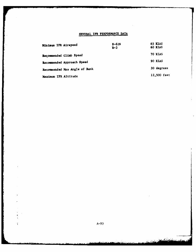
GExERAL in1 PER oRmA~cE DATA
Mmiium in1Airspeed S-61N 45 MlSB-3 60 [LAS
Recommended Climb Speed 70 [lAS
Recommended Approach Speed 90 [lAS
Recomended Max Angle of Bank 30 degrees
)IAx4mink17 ltitude 12.500 feet
A- 93
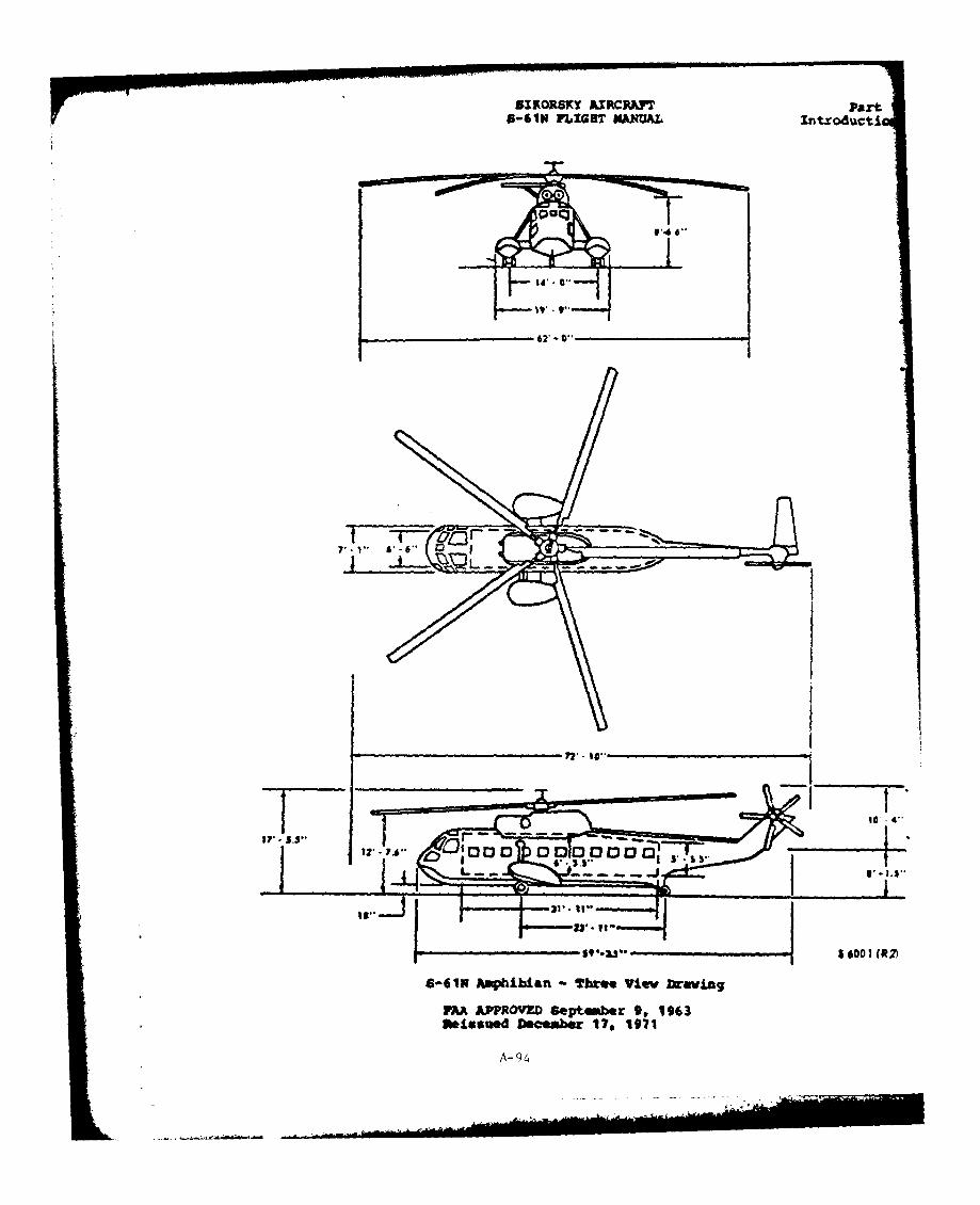
SIKORSKY AtCPhF Part86 IN FLIGHT NAJNUAL Intxoducti
dip--
V - $T, 1 $1,
6613N Ampiblan Tbree View ftev"lg
MA #"ROME "Skpter 9, 1963Vwissued December 179 1971
A- 94
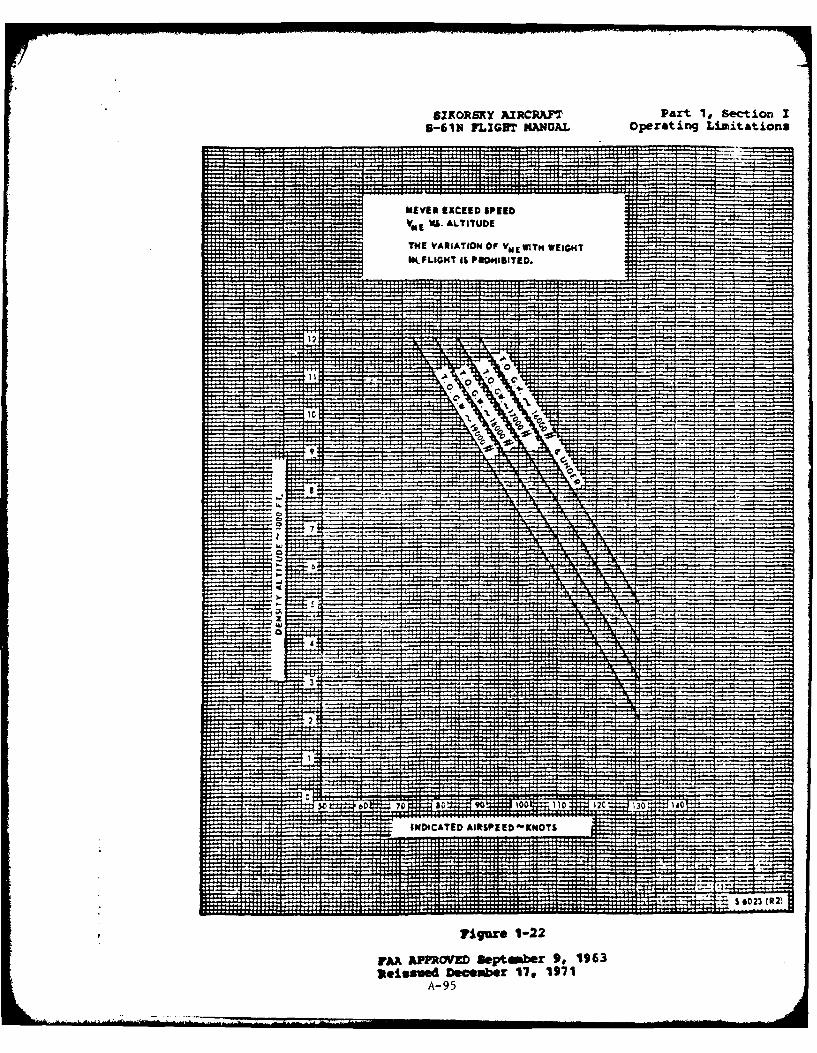
SZKORSKY AIRCRAFT Part 1, Section I6-6u1 FLIGBT MMANAL operating Limitations
'I HH4.4i
NE VER EXCEED SPEED
v* V. ALTITUDE
.......... .THE VARIATION OF Vd E WITH WEIGHT
WFLGH ISROE .PHBIE. 16
9-9
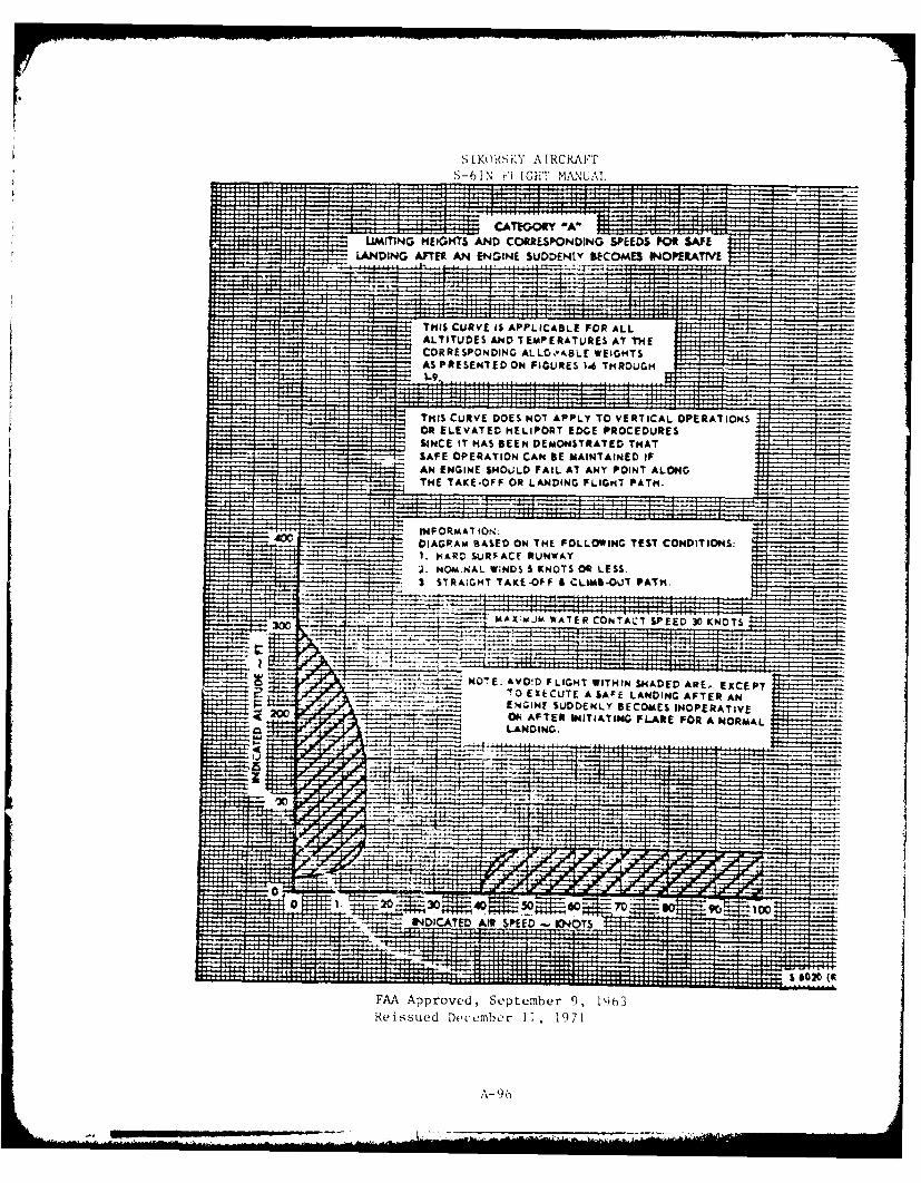
SIKORS'KY ATRCRAFTS-61\ i'l IGHT MAINUAI,
Hi-H.1
CATEOM 'A"LLMMNG HEIGHTS AND CORRESPONDING SPEEDS IP01 SAFE
LANDING AIFTElt AN ENGINE SUDDENLY BECOMES INOPERATTVE. . ......... ......
THIS CURVE IS APPLICABLE FOR ALLALTITUDES AND I EMPERATURES AT THECORRESPONDING ALLO VJIBLE WEIGHTSAS PRESENTED ON FIGURES 1-6 TMROU0MU91 ......
THIS CURVE DOES NOT APPLY TO VERTICAL OPERATIONSOR ELEVATED HELIPORT EDGE PROCEDURESSINCE IT HAS BEEN DEMONSTRATED THATSAFE OPERATION CAN BE MAINTAINED IFAN ENGINE $MOULD FAIL AT ANY POINT ALONGTHE TAKE-OFF OR LANDING FLIGHT PATH.
P iINFORMATION;DIAGRAM 13ASED ON THE FOLLOWING TEST CONDITIONS:1. NARD SURPACE RUNWAYJ. NOMItNAL WINDS 5 KNOTS OR LESS.3, STRAIGHT TAKE-OFF & CLUAB-OUT PATH.
IAX;MJM WATER CONTACT SPEED 31D KN TS
-Z;4
kO7'E: AVO!D FLIGHT WITHIN SHADED ARE- EXCEPTR 70 EXECUTE A SAFE LANDING AFTER AN
ENGINE SUDDENLY BECOMES INOPERATIVE2w OR AFTER INITIATING FLARE FOR A NORMALLANDING.
20 30 40 50 60- n 90 100_ PINDICATED AIR SPEED 1040TS
-- ----- ----- .... .. . ------- -
FAA Approved, September 9, 1963Reissued December 1-1, 19/11
A- () 6
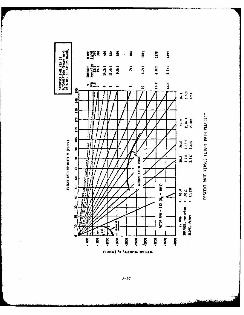
OEw Eqrpm,%
Eq Z,; c
CA vs
#I C Eq
Eqq
E~em .. E
/,4i k ., LA-d~
_ E E
+r +
'gE AA "ALU0M 0M
A- 97

La /I
(V I. AA -A303 .nn
p.A- 9 S
Climb Rates
The following two figures present carpet plots of the best rate of
climb attainable at optimum climb speed and maximum continuous power for
a spectrum of aircraft weight and pressure altitude. One figure presents
data for standard day performance and the other, hot day performance when
temperatures are uniformly 200 C warmer than standard day at each altitude.
Two traces, one labeled HOGE (hover out of ground effect) Boundary and
the other, HIGE (hover in ground effect) Boundary, cross the carpet plots
to identify those combinations of gross weight and altitude at which hover
capability becomes correspondingly limited. (Hover performance is based on
dual engine takeoff power vice maximum continuous power.)
A-99
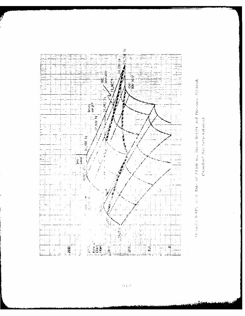
_ _j1
77
La -'7gy
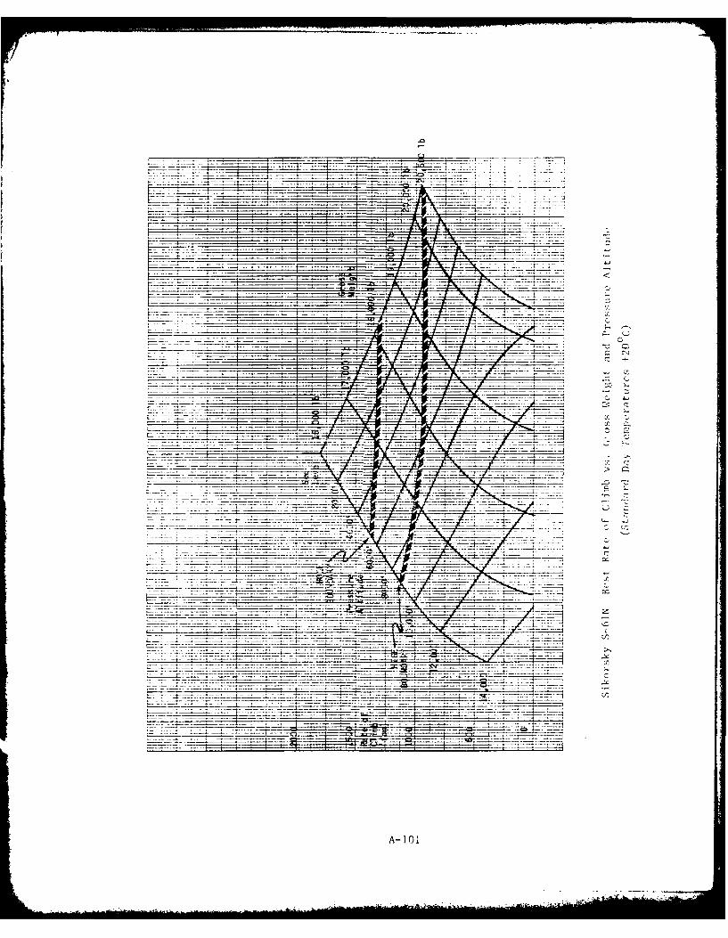
SC
A- 10 1
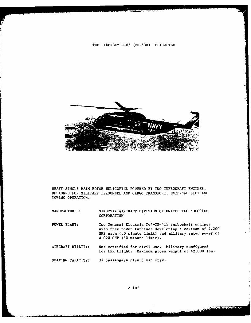
THE SIKORSKY S-65 (RH-53D) HELICOPTER
HEAVY SINGLE MAIN ROTOR HELICOPTER POWERED BY TWO TURBOSHAFT ENGINES,DESIGNED FOR MILITARY PERSONNEL AND CARGO TRANSPORT, EXTERNAL LIFT AND
TOWING OPERATION.
MANUFACTURER: SIKORSKY AIRCRAFT DIVISION OF UNITED TECHNOLOGIES
CORPORATION
POWER PLANT: Two General Electric T64-GE-415 turboshaft engineswith free power turbines developing a maximum of 4.200SHP each (10 minute limit) and military rated power of4,020 SHP (30 minute limit).
AIRCRAFT UTILITY: Not certified for civil use. Military configuredfor IFR flight. Maximum gross weight of 42,000 lbs.
SEATING CAPACITY: 37 passengers plus 3 man crew.
A-102
INTRODUCTION *
The RH-53D is the most powerful of the twin engine versions of the Model
S-ib, manufactured by Sikorsky Aircraft Division of United Technologies.
The helicopter has been adapted from an original design for USMC use as a
heavy assault transport. The primary naval mission is mine countermeasures
in which the aircraft is employed towing waterborne equipment designed to
clear minefields. Secondary missions include cargo lift; externally or
internally, and passenger transport. External cargo lift is limited to
loads of 25,000 lbs. and towing operations may not exceed 15,000 lbs
(using a specialized tow hook, not the cargo hook). The S-65 series ofhelicopters has not been certificated for civil use, so flight performance
data are not completely analogous to data for civil aircraft (e.g. no
minimum IFR airspeed has been defined.) Minimum crew for military opera-
tions consists of pilot, copilot, and crewman.
In standard configuration, the RH-53D helicopter uses retractable
tricycle landing gear; six-bladed fully articulated main rotor and semi-
articulated four-bladed tail rotor.
The RH-53D is powered by two General Electric T64-GE-415 turboshaft
engines employing two stage free power turbines. Maximum power (10 minute
limit) and military power (30 minute limit) limits are defined in terms of
gas generator rpm and turbine inlet temperature limits. For sea level
standard day conditions, these limits correspond to 4,200 SHP and 4,020 SHP
respectively. The transmission is torque limited to 7,560 SHP total or3,780 SHP per engine (for 30 minutes) and 6,400 SHP total continuously
(3200 SHP per engine) .**
The l'imit load factor is 2.38 g's at the maximum gross weight of
42,000 Ibs. The limiting load factor increases to 3.0 g's tor gross
weights of 33,500 lbs. or less.
All Data contained herein have been extracted from the Naval Air
Training and Operating Procedures Standardization (NATOPS) Flight
Manual.
•* Marine Corps CE-53 aircraft are similar, but with less installed power.
CH-53A aircraft utilize T64-GE-6 engines of 3070 SHP maximum and 2890SHP military rated. CH-53D aircraft (the most widely used) employ
T64-GE-413 engines of 4020 and 3500 SHP respectively. Of the perfor-
mance parameters listed herein only rate-of-climb is affected by these
differences. CH-53A are capable of best rate-of-climb of 1600-2300 fpm
(42,000 lb GW-30,000 lb GW) and CH-53D are capable of 2100-2900 fpm
(42,00 lb GW-30,0001b GW).
A-103
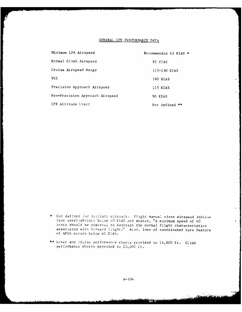
GENERAL IFR PERFORMANCE DATA
Minimum IFR Airspeed Recommended 40 KIAS
Normal Climb Airspeed 85 KIAS
Cruise Airspeed Range 115-130 KIAS
VNE 160 KIAS
Precision Approach Airspeed 115 KIAS
Non-Precision Approach Airspeed 90 KIAS
IFR Altitude Limit Not defined **
Not defined for military aircraft. Flight manual cites airspeed indica-tion unreliability below 40 KIAS and states, "A minimum speed of 40knots should be observed to maintain the normal flight characteristicsassociated with forward flight." Also, loss of coordinated turn featureof AFCS occurs below bO KIAS.
** Hover and cruise performance charts provided to 14,000 ft. Climb
performance charts provided to 20,000 ft.
A-104

NAVAIR Ol-H53AAA-1
17 FT 9 IN.
K 10 FT I
10 F T16
FT 2 IN.
6~~1 FT 1..8 II.N.F
55F FT2 6INN
23 FAT I1I IN.
-~85 FT 8 IN.
FT ~ ~ ~ ~ ~ 6 2.4 5.5 IN.BAESA TTI RO
72~~: FTF.3TN
iTFT3 FTl
CAP~~~~~I N.lFTII N 0F
I~~6 FT1IN
737 FT T. IN.N
A FT~ 2.BN IH LDSA SAI RO
/ 1A -1 0
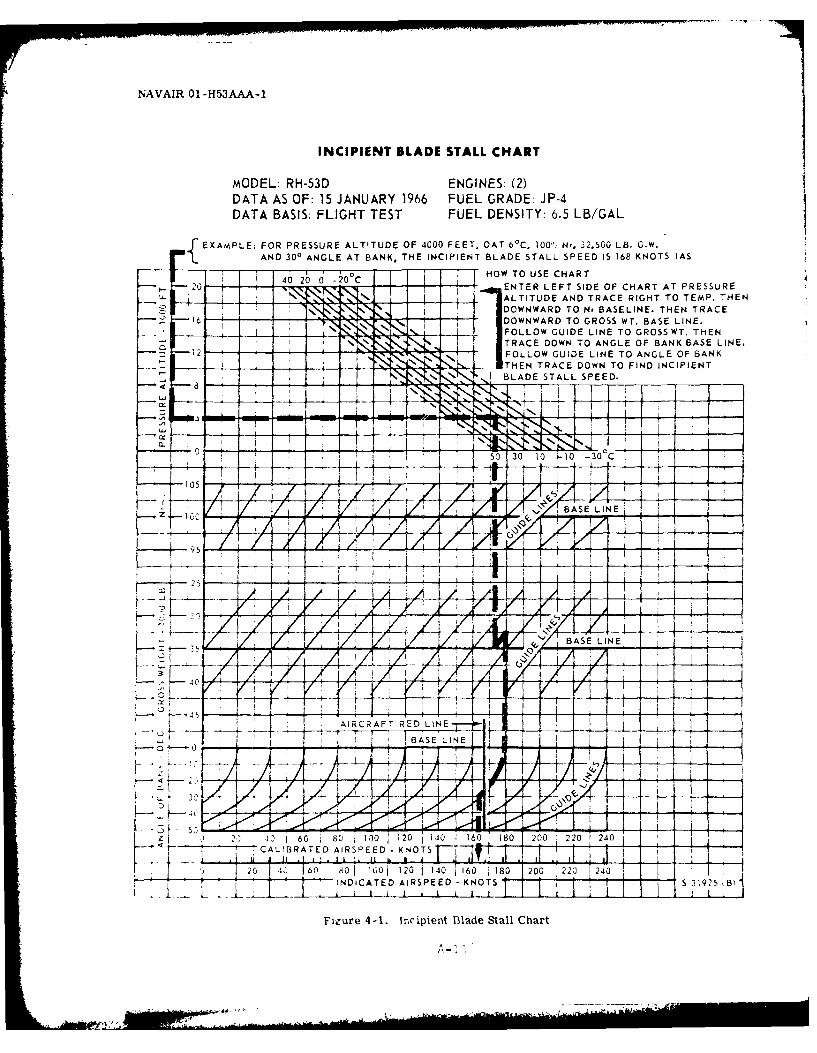
NAVAIR O1-H53AAA-1
INCIPIENT BLADE STALL CHART
MODEL: RH-53D ENGINES: (2)DATA AS OF: 15 JANUARY 1966 FUEL GRADE: JP-4DATA BASIS: FLIGHT TEST FUEL DENSITY: 6.5 LB/GAL
fEXAMPLE: FOR PRESSURE ALTITUDE OF 4000 FEET, OAT 60 C, 100",, N,, 32.500 LB. G.W.]~AND 300 ANGLE AT BANK, THE INCIPIENT BLADE STALL SPEED IS 168 KNOTS IAS
-~ 4000' ~C V K IL HOW TO USE CHART420 ENTER LEFT SIDE OF CHART AT PRESSURE
S _ -ALTITUDE AND TRACE RIGHT TO TEMP. THENDOWNWARD TO Hr BASELINE. THEN TRACE
16 DOWN WARD TO GROSS Wr. BASE LINE.i OLLOW GUIDE LINE TO GROSS WT. THEN
__ __ V± TRACE DOWN TO ANGLE OF BANK BASE LINE.12 FOLLOW GUIDE LINE TO ANGLE OF BANK
T -HEN TRACE DOWN TO FIND INCIPIENT
cx
z __V /Q BASE LINE,
Al_ ,-- f 7I+tif
2 4J160 80 100 120 1 40 160 180 200 1 220 t 24 O -
TCALIBRATED AIRSPEED .KNOT~
r, 1 412 140 60 180 200 20 *t4
14 . iCAE AIRSPEED - KNOTS- jIIIII, S319 B
Figure 4-1. In~cipient Blade Stall Chart
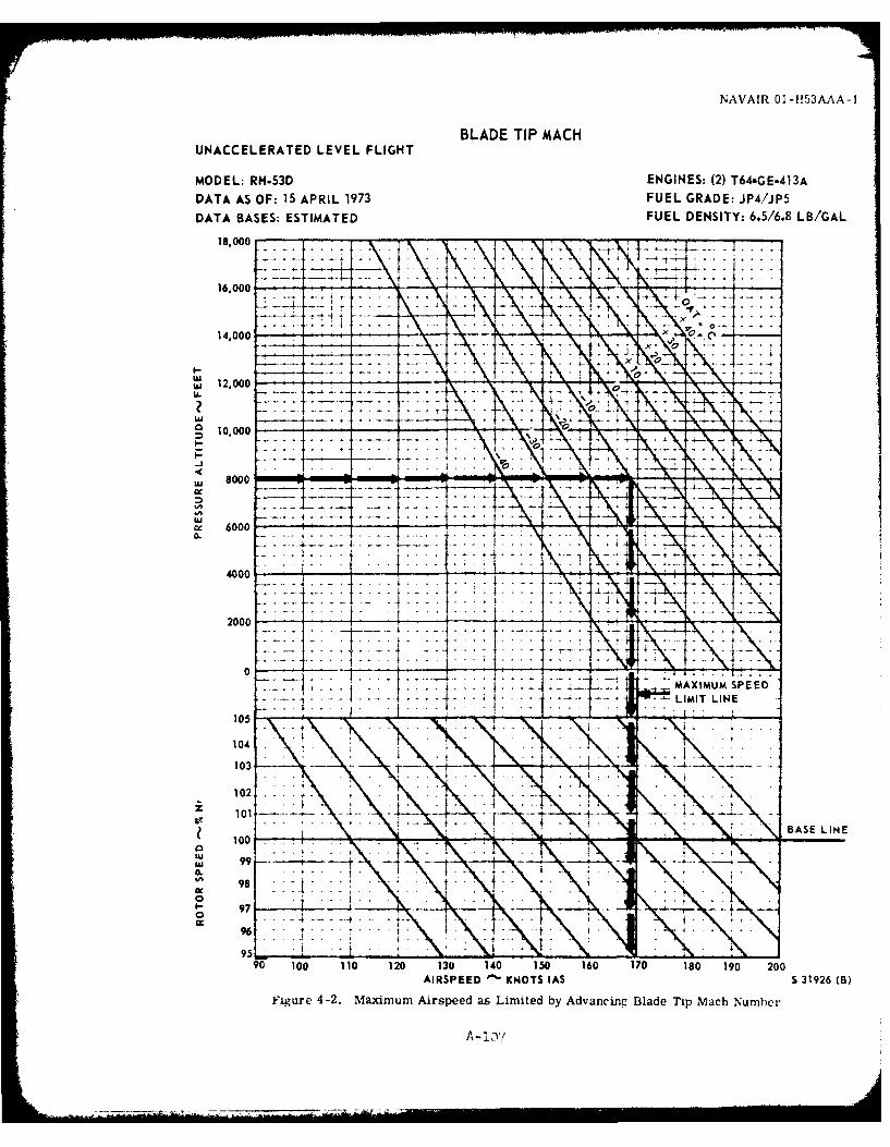
NAVAIR 01-1153AAA-1
BLADE TIP MACHUNACCELERATED LEVEL FLIGHT
MODEL: RH.53D ENGINES: (2) T64-GE-413ADATA AS OF: 15 APRIL 1973 FUEL GRADE: JP4/JP5DATA BASES: ESTIMATED FUEL DENSITY: 6.5/6.8 LB/GAL
18-000 - - -I16,000
14,000 * --.- -
S12,000 - - ~
0 ,o
j 1000-n-
w~ - 7
S6000-- -
4000 - --
2000 - -
10
LIBASE LINE
10
00
1A - I C)
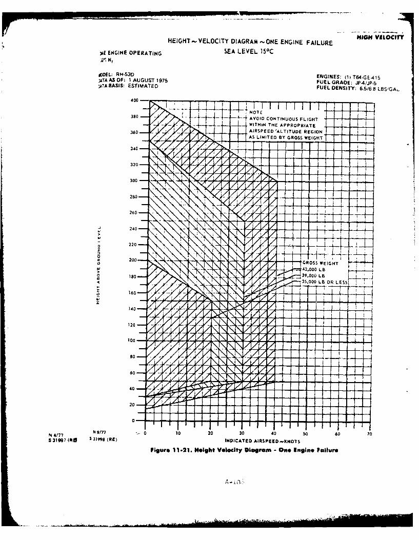
HEIGHT-VELOCITY DIAGRAM -ONE ENGINE FAILURE HIHILIY
YE ENGINE OPERATING SEA LEVEL 150C
0DDEL: RH-53D ENGINES: (IiT64.GEA15DATA AS OF: I AUGUST 1975 FUEL GRADE: JP.4/JP.5)ATA BASIS: ESTIMATED FUEL DENSITY: 6.5/6.8 LOSIGAL
380 AVOID CONTINUOUS FLIGHT- - -WITHIN THE APPROPRIATE
360- AIRSPEED 'ALTITUDE REGIONI AS LIMITED BY GROSS WEIGHT
340.
30 - -p -i
J 40
IL-
2400- --
180 -A 00 LB
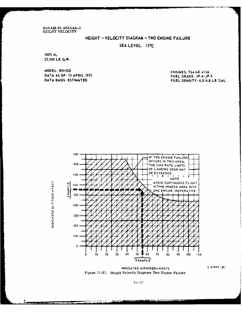
NAVAIR1 01-H53AAA-1HEIGHT VELOCITY
HEIGHT VELOCITY DIAGRAM TWO ENGINE FAILURE
SEA LEVEL 150C
100% N,33,500 LB G.W.
MODEL: RH-53D ENGINES: T64-GE-413ADATA AS OF: 15 APRIL 1973 FUEL GRADE: JP-4,'JP-5DATA BASIS: ESTIMATED FUEL DENSITY: 6.5/6.8 LB 'GAL
OCCURS IN THIS AREA.
-- OF LANDING GEAR MAY
- AVOID CONTINUOUS FLIGHT
ONE ENGINE INOPERATIVE
'740
Uj
00
0 10 20 30 40 50 60 70 80 90 100 110
EXAMPLE
INDICATED AIRSPEED,-KNOTS S 31997 8B)
Figure 11-21. Height Velocity Diagram Two Engine Failure
A -1. ,
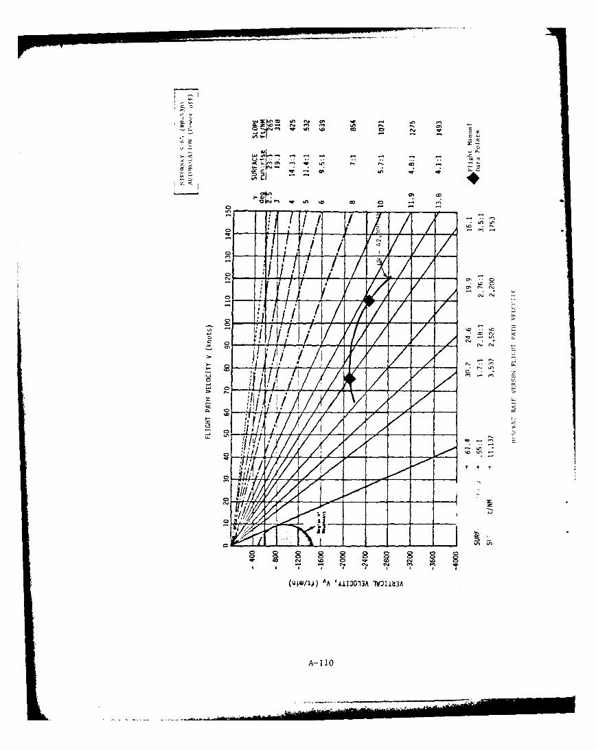
-o M C".-
CL
'r <:
C1. cI
0 1 //
o -o
101
I-X
cv %0
A- 110
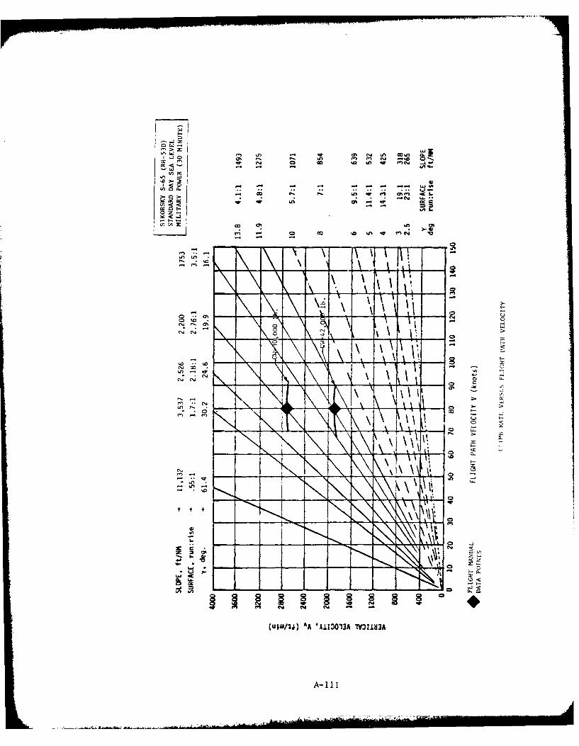
LaC~~~% C - - - - --
cL.3
vi w U, 0% M K L
14 -l 0o "I0%l * %'
m -!
u ,
! 41 u
c~j a% u-
7:0e',j ou
Ln0
In
Z cm
(UjW/jj) AA 'AI303A MUML~3
A- Ill
Climb Rates
The following two figures present carpet plots of the best rate of
climb attainable at optimum climb speed and maximum continuous power for
a spectrum of aircraft weight and pressure altitude. One figure presents
data for standard day performance and the other, hot day performance when
temperatures are uniformly 20°C warmer than standard day at each altitude.
Two traces, one labeled HOGE (hover out of ground effect) Boundary and
the other, HIGE (hover in ground effect) Boundary, cross the carpet plots
to identify those combinations of gross weight and altitude at which hover
capability becomes correspondingly limited. (Hover performance is based on
dual engine takeoff power vice maximum continuous power.)
A-112
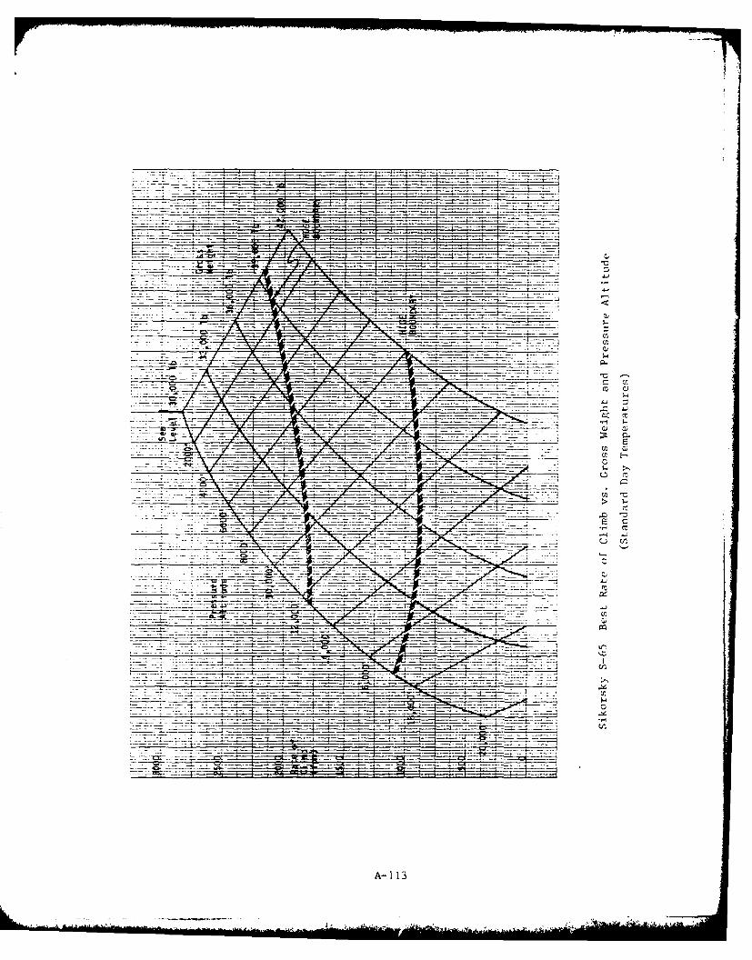
4A4
C)
4jCC C
.,-O~
C) C)
---- -- C-
:77 -lo
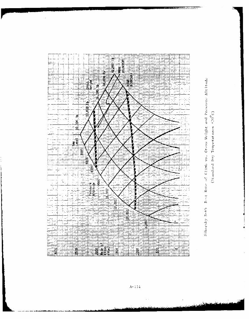
- - - - ~
4j4
17 -- - - ------ ----
A- 114
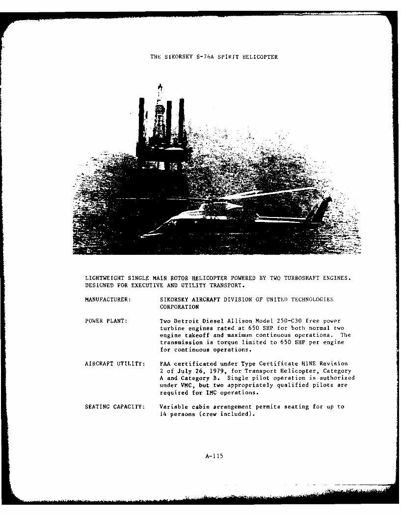
THE SIKORSKY S-76A SPIRIT HELICOPTER
4
LIGHTWEIGHT SINGLE MAIN ROTOR HELICOPTER POWERED BY TWO TURBOSHAFT ENGINES.
DESIGNED FOR EXECUTIVE AND UTILITY TRANSPORT.
MANUFACTURER: SIKORSKY AIRCRAFT DIVISION OF UNITED TECHNOLOGIES
CORPORATION
POWER PLANT: Two Detroit Diesel Allison Model 250-C30 free power
turbine engines rated at 650 SHP for both normal twoengine takeoff and maximum continuous operations. The
transmission is torque limited to 650 SHP per engine
for continuous operations.
AIRCRAFT UTILITY: FAA certificated under Type Certificate HINE Revision
2 of July 26, 1979, for Transport Helicopter, CategoryA and Category B. Single pilot operation is authorized
under VMC, but two appropriately qualified pilots are
required for IMC operations.
SEATING CAPACITY: Variable cabin arrangement permits seating for up to
14 persons (crew included).
A-115
INTRODUCTION
The S-76A Spirit is a 14-place lightweight helicopter manufactured by
the Sikorsky Aircraft Division of The United Technologies Corporation. The
helicopter was designed for civil use in executive and utility transport
roles. It has no military counterpart. Consequently, the market Laphasis
has resulted in IFR certification within the basic type certificate.
Standard configuration includes a four-bladed, single, main rotor with
anti-torque tail rotor. Landing gear is retractable in tricycle configura-
tion.
The S-76A is powered by two Detroit Diesel Allison Model 250-C30
turboshaft engines. Engines and transmission are both rated for 650 SHP
per engine at takeoff and continuous ratings. Following engine failure,
contingency ratings for the remaining engine and transmission permit
operation of one engine at 694 SHP for 2 1/2 minutes or 655 SHP for 30
minutes.
Takeoff and landing operations are presently limited to density
altitudes at and below 6,900 feet. This limitation results from the extent
of demonstration currently reflected in the type certificate. Subsequent
demonstration may be expected to result in less restrictive takeoff and
landing limitations.
Performance data presented herein have been extracted from the Sikorsky
Model S-76A Flight Manual (approval date November 21, 1978, revised October
4, iq79) unless otherwise noted. (Autorotation rate of descent data were
not provided in the Flight Manual, but were instead derived from power
required curves obtained through Sikorsky marketing.)
A-_16
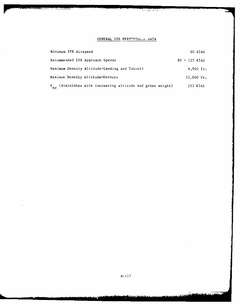
GENERAL IFR PERFnR LA\. DATA
Minimum IFR Airspeed 60 KIAS
Recommended IFR Approach Speeds 80 - 125 KIAS
Maximum Density Altitude-Landing and Takeoff 6,900 ft.
Maximum Density Altitude-Enroute 15,000 ft.
V (diminishes with increasing altitude and gross weight) 155 KIASne
A-11 7
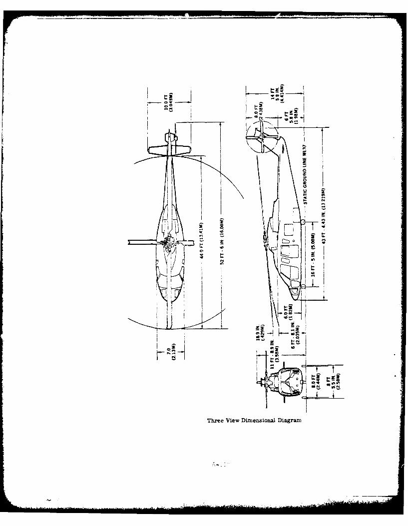
0~ Ow
~emu
-C-
~~Co
In-
The iwDmnsoaKiga
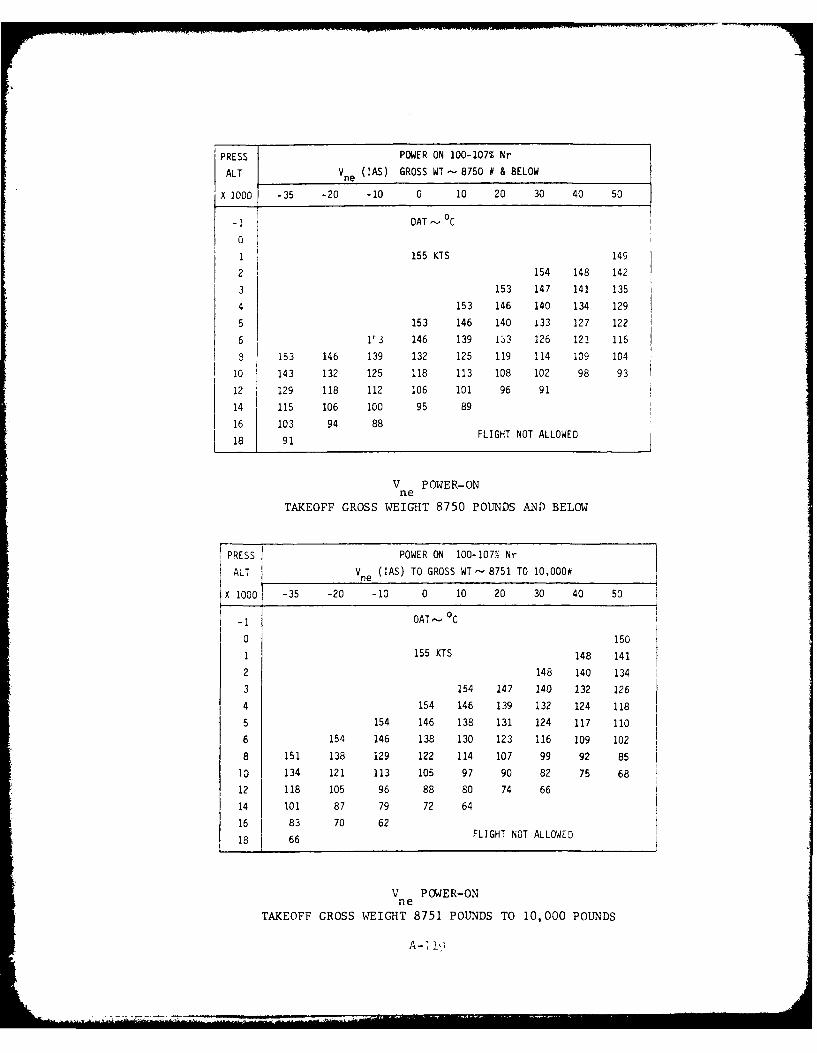
PRESS 1 POWER ON 100-107% Nr
ALT I Vne (IAS) GROSS WT-8750 # & BELOW
X 1000 -35 -20 -10 0 10 20 30 40 50
-1 OAT- C
0
1 155 KTS 149
2 154 148 142
3 153 147 141 135
4 153 146 140 134 129
5 153 146 140 133 127 122
6 1r3 146 139 133 126 121 116
8 153 146 139 132 125 119 114 109 104
10 143 132 125 118 113 108 102 98 93
12 129 118 112 106 101 96 91
14 115 106 100 95 89
16 103 94 88
18 91 FLIGHT NOT ALLOWED
V POWER-ONne
TAKEOFF GROSS WEIGHT 8750 POUNDS AND BELOW
PRESS POWER ON 100-107% Nr
ALT Vne (IAS) TO GROSS WT - 8751 TO 10,000#
x 1000 -35 -20 -10 0 10 20 30 40 50
-1 OAT - C
0 150
1 155 KTS 148 141
2 148 140 1343 154 147 140 132 126
4 154 146 139 132 124 118
5 154 146 138 131 124 117 110
6 154 146 138 130 123 116 109 102
8 151 138 129 122 114 107 99 92 85
13 134 121 113 105 97 90 82 75 68
12 118 105 96 88 80 74 66
14 101 87 79 72 64
16 83 70 62
18 66 FLIGHT NOT ALLOWED
V POWER-ONne
TAKEOFF GROSS WEIGHT 8751 POUNDS TO 10,000 POUNDS
A - I]
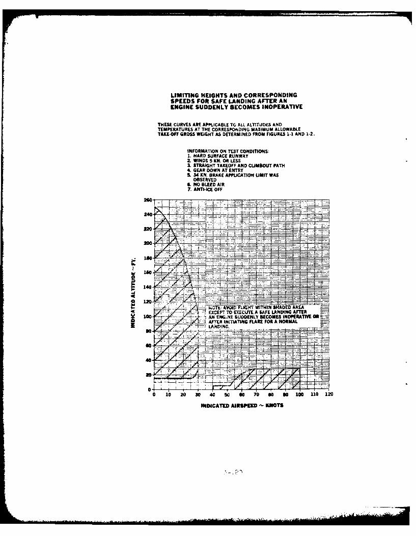
LIMITNG HE19HTS AND CORRESPONDINGSPEEDS FOR SAFE LANDING AFTER ANENGINE SUDDENLY BECOMES INOPERATIVE
THESE CURVES ARE APPLICABLE TO AL. ALr-.TUDES ANDTEMPERATURES AT THE CORRESPOftOING MAXIMUM ALLOWABLETAKE.O#T GROSS WEIGHT AS DETERMINED FROM FIGURES 1-1 AND 1.2.
INFORMATION ON TEST CONDITMOS:1. HARD SURFACE RUNWAY2. WINDS 5 KN. OR LESS& STRAIGHT TAKEOFF AND CUMBOUT PATH4. GEAR DOWN AT ENTRY5. 34 KN. BRAKE APPLICATION LIMIT WAS
OBSERVED6NO BLEED AIR
7. ANTI-ICE OFF
240'
no-
2W.
dc EXEPT TO EXECU~TE A SAFE LANDING AFTER100 AN ENG;NE SUDDENLY BECOMES INOPERATIVE OR
= 4l AMTR INITIATING FLARE FOR A NORMAL-
0 10 20 30 40 50 60 70 0O S0 100 110 120
INDICATED AIRSPEED -~ KNOTS
... .. .- ...
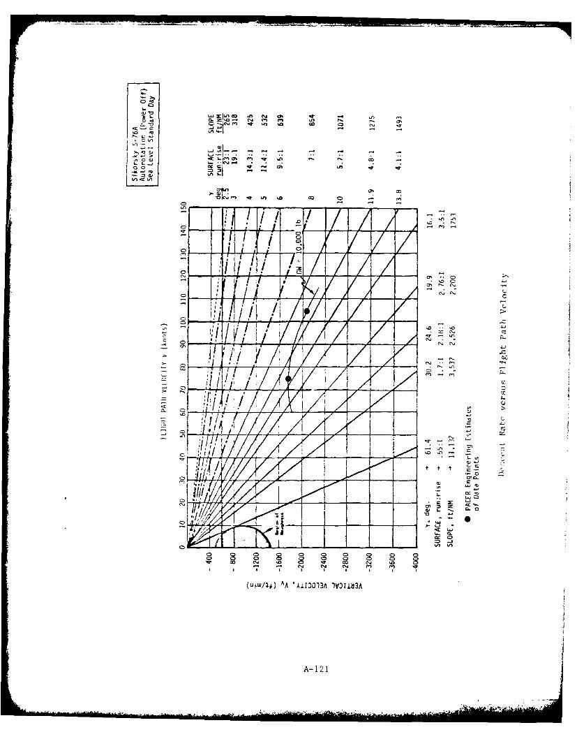
C0 a
c0SC.G
,.... C .-
AA//
100
cl
CD~ ar~~~j -JIll e
0UW4)AA'iD1AI013
A- 1 21
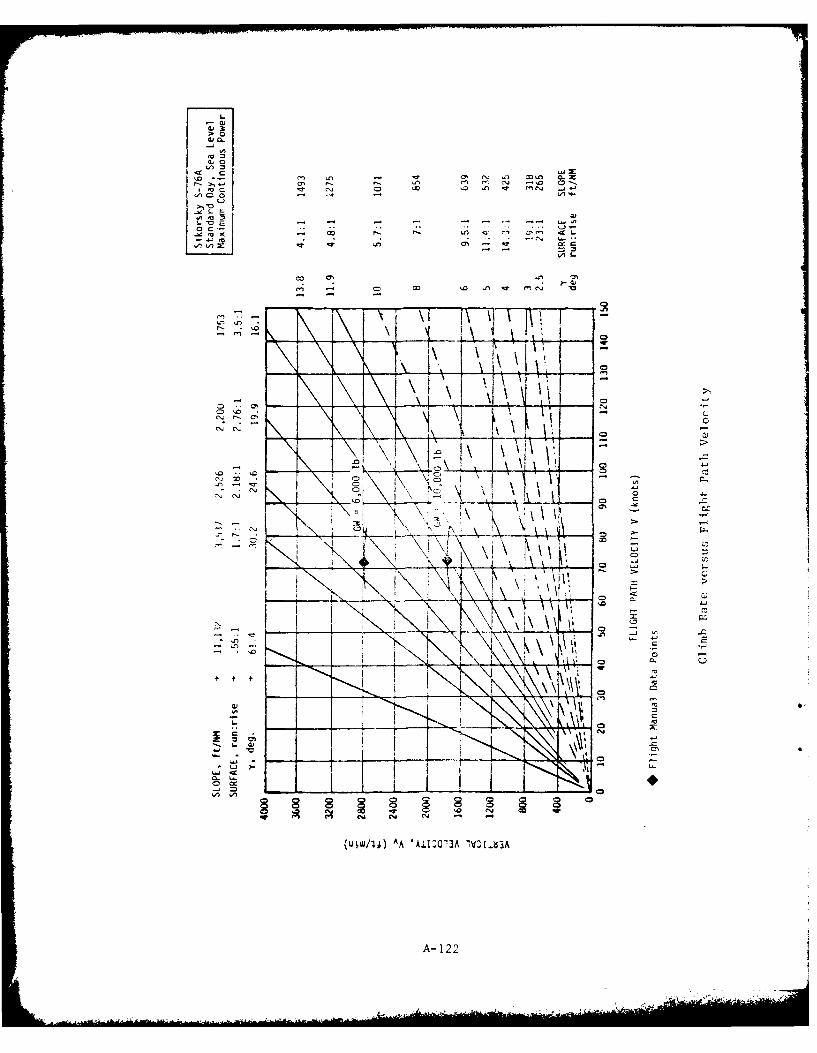
> 0
C) - 0 1 c N . _j~f
- E~ - N f _ - ~ -
S- "o0 . 0 ~ A . N
>~ -D
'A~~ V)2
-o In \ '
C), .4, co
lo4.
I H t
InI
C,4.
(UjW1j) A 'iIM 3A ! ' tld3
A- 02

Climb Rates
The following two figures present carpet plots of the best rate ofclimb attainable at optimum climb speed and maximum continuous power for aspectrum of aircraft weight and pressure altitude. One figure presentsdata for standard day performance and the other, hot day performance whentemperatures are uniformly 20 0Cwarmer than standard day at each altitude.
Two traces, one labeled HOGE (hover out of ground effect) Boundary andthe other, HIGE (hover in ground effect) Boundary, cross the carpetplots to identify those combinations of gross weight and altitude at whichhover capability becomes correspondingly limited. (Hover performance isbased on dual engine takeoff power vice maximum continous power.) For thisaircraft data were not presented which permitted identification of thehover boundaries at the highest altitudes for which climb performance datahave been presented. Consequently, hover boundaries have been extrapolatedto provide an estimate of capabilities. All other data presented in thesefigures are drawn from published Flight Manual Data except the HIGE Boundary.This information is not contained in the Flight Manual so it was drawn frompublished Sikorsky marketing information.
The S-76A Spirit has not yet demonstrated landing and takeoff opera-tions for certification purposes above 6,900 feet density altitude norenroute flight above 15,000 feet density altitude. These heights, there-fore, currently limit the certificated operational envelope and are thus,marked on the carpet plots to graphically provide this information.
A-123
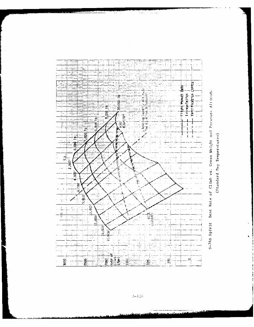
7--7~
-- _ _ _ _ --- --------
--- ------
____________Lt --.I ~ , .
z --
(I) E
-- crC
r U r
a_ 41
A'. \\a
C> .- . d
-4:-

-'- ~ - -- - -
----- ...
ri C:
w +L
do--.
7.- - , ,-
____ C.
A- 125
REFERENCES
1- 1. ANON: U.S. Standard for Terminal Instrument Procedures (TERPS),Department of Transportation, Federal Aviation Administration,
Washington, D.C., July 1976.
2- 1. Gessow, Alfred and Garry C. Myer, Jr., Aerodyna ics of theHelicopter, New York, Frederick Unger Publishing Co., 1967
2- 2. Saunders, George H., Dynamics of Helicopter Flight, New York,
John Wiley & Sons, Inc., 1975
2- 3. Nicolai, Leland M., Fundamentals of Aircraft Design, Xenia, Ohio,METS, Inc., 1975
2- 4. Hurt, H.H., Jr., Aerodynamics for Naval Aviators, U.S. Navy, 1960
2- 5. Green, David L., Helicopter Stability and Control, Naval Test Pilot
School Flight Test Manual, USNTPS-FTM No. 101, 1968
2- 6. Richards, Robert B., Principles of Helicopter Performance, NavalTest Pilot School Textbook, USNTPS-T-No. 1, 1968
2- 7. Moen, Gene C., Daniel J. DiCarlo and Kenneth R. Yenni, A ParametricAnalysis of Visual Approaches for Helicopters, National Aero-
nautics and Space Administration, NASA TN D-8275, 1976
2- 8. ANON: Federal Aviation Regulations, (FARs), Parts 27, 29 and 77,
U.S. Department of Transportation, Federal Aviation Administration,
Washington, D.C.
5- 1. WoiKovitch, Julian and John A. Hoffman, Stability and Control ofHelicopters in Steep Approaches, Vol. I, Summary Report, USAAVLABS
Technical Report No. 70-74A, 1971.
5- 2. Demko, Paul S. and Boschma. Capt James H., "Acvances in DeceleratingSteep Approach and Landing for Helicopter Instrument Approaches",
U.S. Army Avionics R&D Activity, paper presented at the 35th AnnualNational Forum of the American Helicopter Society, Washington, D.C.,
Preprint No. 79-66, May 1979.
R-1/2