study and characterization of bent crystals for laue...
TRANSCRIPT

Noname manuscript No.(will be inserted by the editor)
Study and characterization of bent crystals for Lauelenses
Vincenzo Liccardo · Enrico Virgilli ·Filippo Frontera · Vineeth Valsan · ElisaBuffagni · Claudio Ferrari, · AndreaZappettini · Vincenzo Guidi · ValerioBellucci · Riccardo Camattari
Received: date / Accepted: date
Abstract We report results obtained from the testing of bent Silicon, Germa-nium and Gallium Arsenide crystals, which are being used for focusing photonsin the 90-300 keV energy range, in the framework of the LAUE project. Suchcrystals represent the best choice for building Laue lenses thanks to their highreflectivity and to the narrow Point Spread Function they can provide. Thecharacterization aims to select the best material, to optimize the thicknessand to estimate the curvature radius of the crystal tiles that will be used forbuilding a 20 m focal length Laue lens petal.
Keywords Laue lens · Astrophysics · Bent Crystals · X-ray Telescopes ·X-ray Diffraction · Experimental.
1 INTRODUCTION
Results from flat mosaic crystals selected for the building of a Laue lens proto-type were already reported [1]. However, flat crystals are not suitable for a longfocal length Laue lens, a petal of which is being built within the LAUE project
V. Liccardo · E. Virgilli · F. Frontera · V. ValsanDepartment of Physics, University of Ferrara, Via Saragat 1/c, 44122 Ferrara, ItalyE-mail: [email protected]
V. Liccardo · V. ValsanUniversite de Nice Sophia-Antipolis, Parc Valrose, 06108 Nice Cedex 2, France
E. Buffagni · C. Ferrari, · A. ZappettiniCNR-IMEM Institute, Parco Area delle Scienze 37/A, 43124 Parma, Italy
V. Guidi · V. Bellucci · R. CamattariDepartment of Physics, University of Ferrara, Via Saragat 1/c, 44122 Ferrara, Italy
2 Vincenzo Liccardo et al.
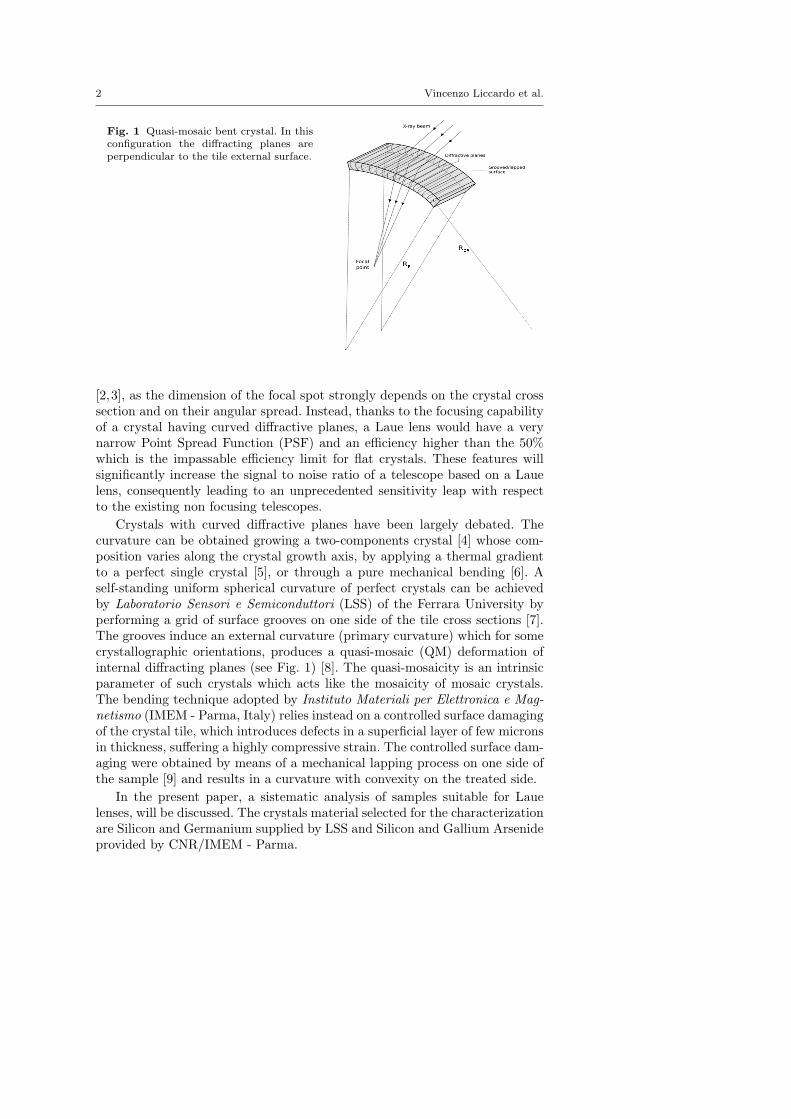
Fig. 1 Quasi-mosaic bent crystal. In thisconfiguration the diffracting planes areperpendicular to the tile external surface.
[2,3], as the dimension of the focal spot strongly depends on the crystal crosssection and on their angular spread. Instead, thanks to the focusing capabilityof a crystal having curved diffractive planes, a Laue lens would have a verynarrow Point Spread Function (PSF) and an efficiency higher than the 50%which is the impassable efficiency limit for flat crystals. These features willsignificantly increase the signal to noise ratio of a telescope based on a Lauelens, consequently leading to an unprecedented sensitivity leap with respectto the existing non focusing telescopes.
Crystals with curved diffractive planes have been largely debated. Thecurvature can be obtained growing a two-components crystal [4] whose com-position varies along the crystal growth axis, by applying a thermal gradientto a perfect single crystal [5], or through a pure mechanical bending [6]. Aself-standing uniform spherical curvature of perfect crystals can be achievedby Laboratorio Sensori e Semiconduttori (LSS) of the Ferrara University byperforming a grid of surface grooves on one side of the tile cross sections [7].The grooves induce an external curvature (primary curvature) which for somecrystallographic orientations, produces a quasi-mosaic (QM) deformation ofinternal diffracting planes (see Fig. 1) [8]. The quasi-mosaicity is an intrinsicparameter of such crystals which acts like the mosaicity of mosaic crystals.The bending technique adopted by Instituto Materiali per Elettronica e Mag-netismo (IMEM - Parma, Italy) relies instead on a controlled surface damagingof the crystal tile, which introduces defects in a superficial layer of few micronsin thickness, suffering a highly compressive strain. The controlled surface dam-aging were obtained by means of a mechanical lapping process on one side ofthe sample [9] and results in a curvature with convexity on the treated side.
In the present paper, a sistematic analysis of samples suitable for Lauelenses, will be discussed. The crystals material selected for the characterizationare Silicon and Germanium supplied by LSS and Silicon and Gallium Arsenideprovided by CNR/IMEM - Parma.
Study and characterization of bent crystals for Laue lenses 3
2 Crystals test apparatus
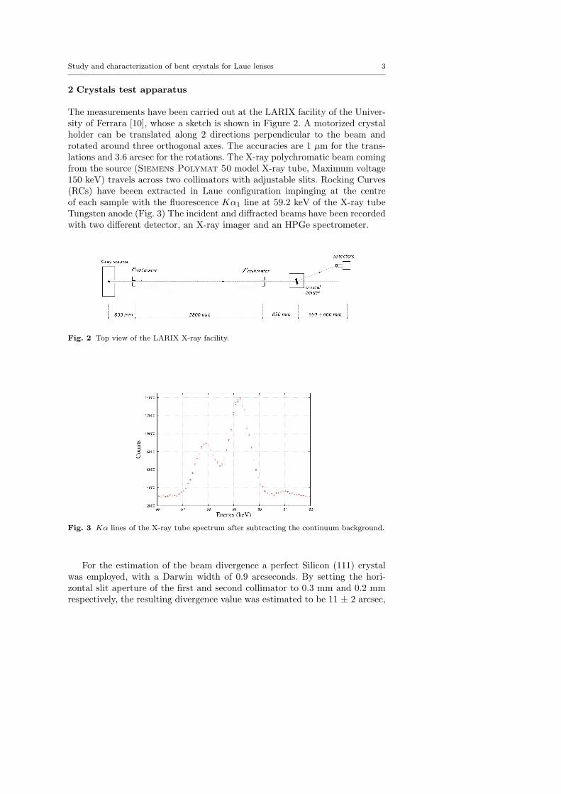
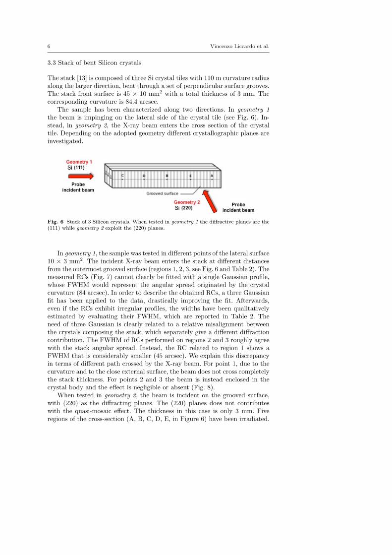
The measurements have been carried out at the LARIX facility of the Univer-sity of Ferrara [10], whose a sketch is shown in Figure 2. A motorized crystalholder can be translated along 2 directions perpendicular to the beam androtated around three orthogonal axes. The accuracies are 1 µm for the trans-lations and 3.6 arcsec for the rotations. The X-ray polychromatic beam comingfrom the source (Siemens Polymat 50 model X-ray tube, Maximum voltage150 keV) travels across two collimators with adjustable slits. Rocking Curves(RCs) have beeen extracted in Laue configuration impinging at the centreof each sample with the fluorescence Kα1 line at 59.2 keV of the X-ray tubeTungsten anode (Fig. 3) The incident and diffracted beams have been recordedwith two different detector, an X-ray imager and an HPGe spectrometer.
Fig. 2 Top view of the LARIX X-ray facility.
Fig. 3 Kα lines of the X-ray tube spectrum after subtracting the continuum background.
For the estimation of the beam divergence a perfect Silicon (111) crystalwas employed, with a Darwin width of 0.9 arcseconds. By setting the hori-zontal slit aperture of the first and second collimator to 0.3 mm and 0.2 mmrespectively, the resulting divergence value was estimated to be 11 ± 2 arcsec,

4 Vincenzo Liccardo et al.
Table 1 Tested samples.
Institute Sample Material Dimensions structure bending
Number (mm) × (mm) × (mm) curvature method
1 Si 15 × 15 × 0.75 Perfect Flat –
2 Si 15 × 15 × 0.75 Perfect Bent (60 m) Surface lapping
IMEM 3 Si 15 × 15 × 0.75 Perfect Bent (27 m) Surface lapping
4 GaAs 15 × 15 × 2 Mosaic Flat –
5 GaAs Rounded shape × 2 Mosaic Bent Surface lapping
6 Si 25 × 25 × 1 Perfect Bent (60 m) Indentations
LSS 7 Si Stack of 3 tiles: 45 × 10 × 1 Perfect Bent (110 m) Indentations
that is a good compromise between brightness and divergence of the beamthat impinges the crystal under test. A subset of the tested crystals providedby the two institutes is shown in Table 1.
3 Measurements and results
3.1 Flat and bent Silicon (220) crystals
A flat perfect and two bent Silicon samples (60 m and 27 m curvature radii)were provided by IMEM-Parma, with dimensions 15 × 15 × 0.75 mm3. Thebending is obtained through the surface lapping technique. Being the crys-tals extracted from the same ingot, their intrinsic properties are expected tobe comparable. Hence, the comparison can provide informations about theefficiency as a function of the applied curvature.
Fig. 4 Plot of the Integrated Reflectivity of the (220) diffraction planes, normalized to theincident beam, as function of the crystal curvature (R=∞, R=60 m, R=27 m).

Study and characterization of bent crystals for Laue lenses 5
RCs were recorded with the 59.2 keV radiation impinging on the 15 ×15 mm2 sample surface parallel to the (001) planes, i.e. using the (220) asdiffracting planes. The integrated reflectivity was estimated for each sampledividing the area under the reflectivity curve by the Kα1 line total numberof incident photons. The continuum radiation spectrum has been subtractedfor the calculation of the integrated reflectivity. As shown in Figure 4, theintegrated reflectivity at 59.2 keV increases linearly as a function of the crystalcurvature. For the 60 m and 27 m curvature radii the integrated reflectivityincreases by a factor 2 and 3, respectively, with respect to that of the flatcrystal.
3.2 Flat and bent Gallium Arsenide (220) mosaic crystals
Two GaAs mosaic samples, coming from the same ingot, were tested byanalysing the radiation coming from the (220) diffractive planes. The anal-ysed samples, one flat and one bent (40 m curvature radius), have the samethickness (2 mm). The recorded RCs are shown in Fig. 5. The intrinsic FWHMof the mosaic spread [11] is obtained from the Gaussian spread FWHMmeas ofthe measured RC through the following equation [12]:
FWHM =√FWHM2
meas − FWHM2div, (1)
where FWHMdiv is the spread due to the beam divergence. We find thatthe peak reflectivity, at 59.2 keV, of the samples is 30-35% with a mosaicity of25-30 arcsec. The applied curvature does not seem to significantly affect themosaicity, being the local mosaic spread unchanged. Nevertheless, the curva-ture influences the global behaviour of the crystal tile allowing the focusingeffect.
Fig. 5 Flat (Left) and bent (Right) GaAs (220) crystals rocking curves collected at 59.2keV, both normalized by the intensity of the incident beam. In the lower panels the residualsbetween data and model are shown in units of sigma.
6 Vincenzo Liccardo et al.
3.3 Stack of bent Silicon crystals
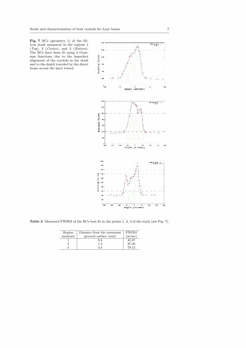
The stack [13] is composed of three Si crystal tiles with 110 m curvature radiusalong the larger direction, bent through a set of perpendicular surface grooves.The stack front surface is 45 × 10 mm2 with a total thickness of 3 mm. Thecorresponding curvature is 84.4 arcsec.
The sample has been characterized along two directions. In geometry 1the beam is impinging on the lateral side of the crystal tile (see Fig. 6). In-stead, in geometry 2, the X-ray beam enters the cross section of the crystaltile. Depending on the adopted geometry different crystallographic planes areinvestigated.
Fig. 6 Stack of 3 Silicon crystals. When tested in geometry 1 the diffractive planes are the(111) while geometry 2 exploit the (220) planes.
In geometry 1, the sample was tested in different points of the lateral surface10 × 3 mm2. The incident X-ray beam enters the stack at different distancesfrom the outermost grooved surface (regions 1, 2, 3, see Fig. 6 and Table 2). Themeasured RCs (Fig. 7) cannot clearly be fitted with a single Gaussian profile,whose FWHM would represent the angular spread originated by the crystalcurvature (84 arcsec). In order to describe the obtained RCs, a three Gaussianfit has been applied to the data, drastically improving the fit. Afterwards,even if the RCs exhibit irregular profiles, the widths have been qualitativelyestimated by evaluating their FWHM, which are reported in Table 2. Theneed of three Gaussian is clearly related to a relative misalignment betweenthe crystals composing the stack, which separately give a different diffractioncontribution. The FWHM of RCs performed on regions 2 and 3 roughly agreewith the stack angular spread. Instead, the RC related to region 1 shows aFWHM that is considerably smaller (45 arcsec). We explain this discrepancyin terms of different path crossed by the X-ray beam. For point 1, due to thecurvature and to the close external surface, the beam does not cross completelythe stack thickness. For points 2 and 3 the beam is instead enclosed in thecrystal body and the effect is negligible or absent (Fig. 8).
When tested in geometry 2, the beam is incident on the grooved surface,with (220) as the diffracting planes. The (220) planes does not contributeswith the quasi-mosaic effect. The thickness in this case is only 3 mm. Fiveregions of the cross-section (A, B, C, D, E, in Figure 6) have been irradiated.
Study and characterization of bent crystals for Laue lenses 7
Fig. 7 RCs (geometry 1) of the Sil-icon stack measured in the regions 1(Top), 2 (Center), and 3 (Bottom).The RCs have been fit using 3 Gaus-sian functions, due to the imperfectalignment of the crystals in the stackand to the depth traveled by the directbeam across the layer tested.
Table 2 Measured FWHM of the RCs best fit in the points 1, 2, 3 of the stack (see Fig. 7).
Region Distance from the outermost FWHManalyzed grooved surface (mm) (arcsec)
1 0.4 45.872 1.5 87.463 2.3 79.12

8 Vincenzo Liccardo et al.
Fig. 8 Top view of the bent Silicon stack. The different paths crossed by the radiation arealso visible.
Fig. 9 Diffracted counts from different regions of the stack.
The results of the test (Fig. 9) confirm the fact that the crystals compos-ing the stack are not perfectly aligned with each other, with the maximummisalignment being more relevant in the external regions (C and A).
3.4 Quasi-mosaic Silicon (111) crystal
The sample cross-section is 20 × 20 mm2 and 2 mm thickness, with primarycurvature radius RP of 60 m. The diffracting planes (111), in transmission con-figuration, are orthogonal to the square surface. From the theory of elasticityof bent crystals diffraction, the ratio between the internal curvature radiusRQM and RP is ∼ 2.614 for the orientation considered [14], with a consequentQM curvature of the diffracting (111) planes of 157 m.From the measured rocking curve, the derived angular spread is 12 ± 2 arcsecwhich agrees with the expectations if the beam divergence and the primarycurvature seen by the incident beam are considered. The experimental RC, at

Study and characterization of bent crystals for Laue lenses 9
59.2 keV, is reported in Figure 10. Due to the beam divergence the measuredpeak value is lower than the intrinsic diffraction efficiency.
Fig. 10 Measured and theoretical RCs. The dashed line represents the theoretical functionas obtained by convolving the rectangular shape distribution of the secondary curvature,with the Gaussian distribution of the beam divergence, taking also into account the beamwidth. Red points are the recorded intensities of the diffracted beam.
The results show that Silicon is a good material for Laue lenses. Unfortu-nately, the required thickness for a satisfying efficiency at energies beyond 150keV is too high (Fig. 11 left) [15] since with the current bending techniquesbent crystals with thickness greater than 2 mm cannot be manufactured.On the other hand, Germanium crystals, which are expected to have the sameproperties as Silicon because of their identical crystalline structure, at presentare more suitable for a Laue lens working at high energies (>100 keV) thanksto their requested best thickness (Fig. 11 right).
Fig. 11 Bent Silicon (Left) and Germanium (Right) crystals best thickness as a functionof energy for different diffracting planes.
10 Vincenzo Liccardo et al.
4 Curvature test of the crystal tiles produced for the LAUE project
One of the main goals of the LAUE project is the development and constructionof a lens petal, with a focal length of 20 m, made of Ge (111) and GaAs(220) crystals whose curvature radius must be 40 m. It has been recentlydemonstrated [15] that the advantage of the focusing effect of bent crystalscan be fully exploited if only the proper curvature is obtained. A reasonablevalue of 5% accuracy in the curvature radius can be accepted. In the LARIXfacilty a run of measurements has been realized to test whether or not thecurvature radius of each tile is consistent with that requested by the project.
4.1 Technique for the crystal curvature determination
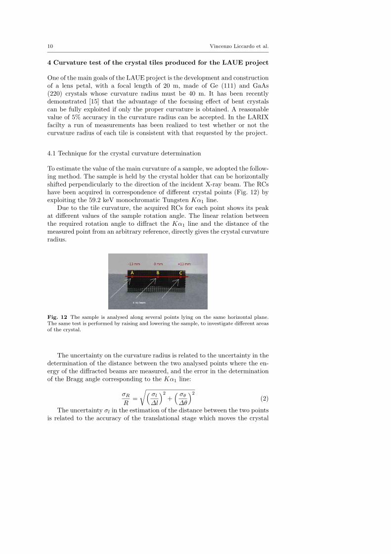
To estimate the value of the main curvature of a sample, we adopted the follow-ing method. The sample is held by the crystal holder that can be horizontallyshifted perpendicularly to the direction of the incident X-ray beam. The RCshave been acquired in correspondence of different crystal points (Fig. 12) byexploiting the 59.2 keV monochromatic Tungsten Kα1 line.
Due to the tile curvature, the acquired RCs for each point shows its peakat different values of the sample rotation angle. The linear relation betweenthe required rotation angle to diffract the Kα1 line and the distance of themeasured point from an arbitrary reference, directly gives the crystal curvatureradius.
Fig. 12 The sample is analysed along several points lying on the same horizontal plane.The same test is performed by raising and lowering the sample, to investigate different areasof the crystal.
The uncertainty on the curvature radius is related to the uncertainty in thedetermination of the distance between the two analysed points where the en-ergy of the diffracted beams are measured, and the error in the determinationof the Bragg angle corresponding to the Kα1 line:
σRR
=
√( σl∆l
)2
+( σθ∆θ
)2
(2)
The uncertainty σl in the estimation of the distance between the two pointsis related to the accuracy of the translational stage which moves the crystal
Study and characterization of bent crystals for Laue lenses 11
and allows the beam to impinge on two adjacent points of the sample. Theaccuracy is 1 µm that for a typical distance ∆l ∼ 4 mm gives:( σl
∆l
)∼ 2.5× 10⁻⁴ (3)
The actuator angular uncertainty is instead 10−4 degrees. For two pointsat distance ∆l the value of ∆θ is given by the ratio between their distance andthe curvature radius (approximately 40 m):( σθ
∆θ
)∼ 10−4
few × 10−3∼ few × 10−2 (4)
The translational stage uncertainty is then negligible compared with theangular one. Based on the above considerations a curvature radius can be esti-mated with an uncertainty better than 2 m (5%) for a sample with tentatively40 m curvature radius.
4.2 Tested crystals
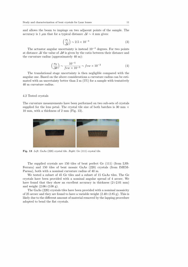
The curvature measurements have been performed on two sub-sets of crystalssupplied for the lens petal. The crystal tile size of both batches is 30 mm ×10 mm, with a thickness of 2 mm (Fig. 13).
Fig. 13 Left : GaAs (220) crystal tile. Right : Ge (111) crystal tile.
The supplied crystals are 150 tiles of bent perfect Ge (111) (from LSS-Ferrara) and 150 tiles of bent mosaic GaAs (220) crystals (from IMEM-Parma), both with a nominal curvature radius of 40 m.
We tested a subset of 45 Ge tiles and a subset of 15 GaAs tiles. The Gecrystals have been provided with a nominal angular spread of 4 arcsec. Wehave found that they show an excellent accuracy in thickness (2÷2.01 mm)and weight (2.06÷2.08 g).
The GaAs (220) crystals tiles have been provided with a nominal mosaicityof 25 arcsec and they are found to have a variable weight (2.40÷2.85 g). This islikely due to the different amount of material removed by the lapping procedureadopted to bend the flat crystals.

12 Vincenzo Liccardo et al.
Table 3 Curvature radii of the Ge (111) samples analyzed for the LAUE project.
Sample Curvature Sample Curvature Sample CurvatureNumber Radius (m) Number Radius (m) Number Radius (m)
8 44.7 29 43.0 58 41.89 44.2 30 40.5 68 42.810 37.4 31 37.4 71 43.711 44.3 32 26.0 72 44.713 44.7 33 40.5 73 43.114 37.3 34 43.3 80 37.915 40.5 35 42.7 81 38.416 38.5 36 38.0 82 44.217 41.8 37 33.0 83 30.421 39.5 47 54.5 92 40.924 46.4 48 45.7 94 52.625 51.1 49 39.4 94 52.626 47.7 50 41.3 119 39.327 43.5 51 42.3 126 47.028 41.5 56 41.2 153 44.3
4.2.1 Germanium (111) crystal tiles
The results of the curvature radius measurements are shown in Table 3. All theGe (111) crystal tiles show a bending radius extremely uniform throughout thecrystal, even if in some cases we found a discrepancy between the curvaturemeasured with a profilometer at the LSS laboratory and that measured withthe LARIX facility. For those crystals that exhibit a curvature radius smallerthan that expected, it has been demonstrated that through an etching process,is possible to adjust the curvature to the value of 40 meters with an uncertaintyof 5% [16]. Some examples of the crystal curvature measurements are given inFig. 14.
Fig. 14 Bending estimations for different samples of Germanium. The measured radii arecompared with the expected curvature (40 m). The x and y axes show respectively thedistance from the center of the crystal (zero), and the angle required to diffract the 59.2keV photons.

Study and characterization of bent crystals for Laue lenses 13
4.2.2 Gallium Arsenide (220) crystal tiles
The set of GaAs tested crystals and results are given in Table 4, where thecurvature radii measured at IMEM and at LARIX facility are also compared.It can be observed a discrepancy between our and IMEM estimates. In thiscase, the curvature determination has been obtained with the same technique,with the exception of the configuration adopted, Bragg (reflection) at IMEM[17] and Laue (transmission) at LARIX.
Table 4 Curvature radii of the GaAs (220) set of samples.
Sample Weight Rc Rc Deviation (%) Mosaicity (arcsec)Number (g) IMEM LARIX IMEM-LARIX LARIX
1 2.40 40.3 35.0 13.9% 25.52 2.05 42.4 39.5 7.3% 27.43 2.66 41.9 39.3 6.5% 23.64 2.67 38.8 39.2 1.1% 21.2
4.8 2.55 39.4 35.9 8.75% -4.9 2.62 38.7 36.3 6% -5 2.85 40.0 38.2 4.5% 25.2
5.2 2.35 40.0 39.9 0.2% -5.10 2.42 40.0 40.0 -% -
6 2.60 40.0 36.5 9.2% 23.46.4 2.65 40.0 38.9 0.2% -6.6 2.62 42.0 40.5 3.75% -6.10 2.52 38.8 36.8 5.0% -6.11 2.60 38.6 34.7 9.7% -6.12 2.55 41.1 42.38 3.2% -
Some evidence of non-uniform curvature of some GaAs samples has beenrevealed that could be due to the presence of low angle grain boundaries inGaAs crystals. A distortion for some of the samples is observed at the edgesof the tiles (an example is the crystal C03 in Figure 15).
Fig. 15 Bending estimations for some samples of GaAs. The measured radii are comparedwith the expected curvature (40 m). The x and y axes show respectively the distance fromthe center of the crystal (zero), and the corresponding 59.2 keV Bragg angle.

14 Vincenzo Liccardo et al.
Fig. 16 Mosaic GaAs (220) rocking curve as recorded at the LARIX facility. The FWHMof the gaussian fit is 31.2 arcsec. After the correction of the beam divergence, the mosaicityvalue obtained was ∼ 25 arcsec.
Figure 16 shows an example of rocking curve of a GaAs crystal. From therecorded RCs and Eq. 1 the mosaicity has been estimated for some samples,and the results are in agreement with the expectations (Table 4).
4.3 Distribution of the curvature radii
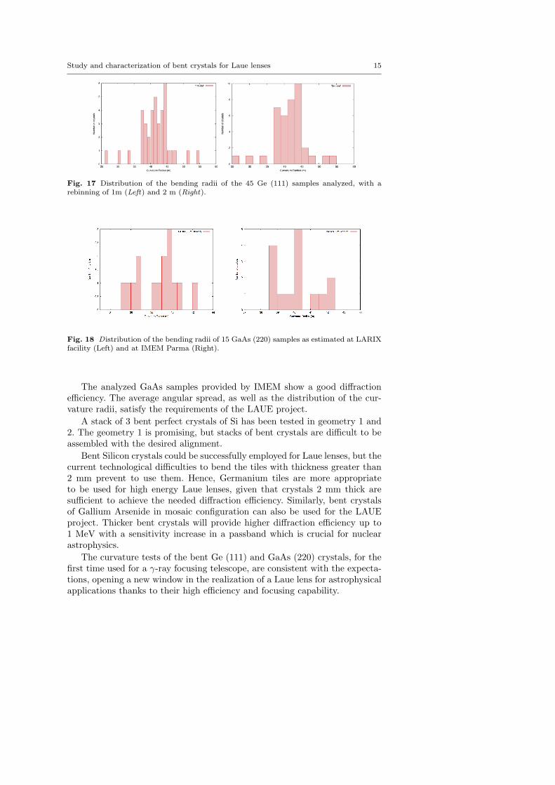
Figure 17 shows the distribution of the measured curvature radii of Ge (111)crystal tiles. We have found that 36% of the tested tiles have a curvatureradius of 40 m within 5%, while 60% of the tiles have a curvature radius of40 m within 10%. Crystals with a curvature radius that does not satisfy therequirements will be further treated for refining the curvature.
For GaAs (220) crystal tiles, due to the small number of tested crystals ithas not been possible to get a significant distribution of the curvature radii(see Fig. 18). In any case, from the results obtained, we can see that 44% ofthe samples tested have a curvature of 40 m within 5%, whereas the curvatureof 83% of the tiles is 40 m within 10%. Also for GaAs tiles the curvature canbe correct to fulfil the 40 m request, by an etching procedure if the curva-ture exceed the requested value and by a further surface treatment when thecurvature is too low.
5 Conclusions
In this paper, various bent and flat crystals have been tested for their pos-sible use in Laue lenses. We have also performed curvature measurements toestablish the real curvature of the supplied crystals. For each sample, angularspread and diffraction efficiency at 59.2 keV have been measured as a func-tion of the crystal thickness and curvature radius, and compared with thoseobtained using flat crystals.
Study and characterization of bent crystals for Laue lenses 15
Fig. 17 Distribution of the bending radii of the 45 Ge (111) samples analyzed, with arebinning of 1m (Left) and 2 m (Right).
Fig. 18 D istribution of the bending radii of 15 GaAs (220) samples as estimated at LARIXfacility (Left) and at IMEM Parma (Right).
The analyzed GaAs samples provided by IMEM show a good diffractionefficiency. The average angular spread, as well as the distribution of the cur-vature radii, satisfy the requirements of the LAUE project.
A stack of 3 bent perfect crystals of Si has been tested in geometry 1 and2. The geometry 1 is promising, but stacks of bent crystals are difficult to beassembled with the desired alignment.
Bent Silicon crystals could be successfully employed for Laue lenses, but thecurrent technological difficulties to bend the tiles with thickness greater than2 mm prevent to use them. Hence, Germanium tiles are more appropriateto be used for high energy Laue lenses, given that crystals 2 mm thick aresufficient to achieve the needed diffraction efficiency. Similarly, bent crystalsof Gallium Arsenide in mosaic configuration can also be used for the LAUEproject. Thicker bent crystals will provide higher diffraction efficiency up to1 MeV with a sensitivity increase in a passband which is crucial for nuclearastrophysics.
The curvature tests of the bent Ge (111) and GaAs (220) crystals, for thefirst time used for a γ-ray focusing telescope, are consistent with the expecta-tions, opening a new window in the realization of a Laue lens for astrophysicalapplications thanks to their high efficiency and focusing capability.

16 Vincenzo Liccardo et al.
Acknowledgements The authors wish acknowledge the financial support by the ItalianSpace Agency (ASI) through the project “LAUE - Una Lente per i raggi Gamma” undercontract I/068/09/0. V. Valsan and V. Liccardo are supported by the Erasmus MundusJoint Doctorate Program by Grant Number 2010-1816 from the EACEA of the EuropeanCommission.
References
1. E. Virgilli, F. Frontera, V. Valsan, V. Liccardo, V. Carassiti, F. Evangelisti,S. Squerzanti, in Society of Photo-Optical Instrumentation Engineers (SPIE) Confer-ence Series, vol. 8147 (2011), vol. 8147. DOI 10.1117/12.895233
2. E. Virgilli, F. Frontera, V. Valsan, V. Liccardo, V. Carassiti, S. Squerzanti, M. Statera,M. Parise, S. Chiozzi, F. Evangelisti, E. Caroli, J. Stephen, N. Auricchio, S. Silvestri,A. Basili, F. Cassese, L. Recanatesi, V. Guidi, V. Bellucci, R. Camattari, C. Ferrari,A. Zappettini, E. Buffagni, E. Bonnini, M. Pecora, S. Mottini, B. Negri, in Society ofPhoto-Optical Instrumentation Engineers (SPIE) Conference Series, vol. 8861 (2013),vol. 8861. DOI 10.1117/12.2023593
3. F. Frontera, E. Virgilli, V. Valsan, V. Liccardo, V. Carassiti, E. Caroli, F. Cassese,C. Ferrari, V. Guidi, S. Mottini, M. Pecora, B. Negri, L. Recanatesi, L. Amati, N. Au-ricchio, L. Bassani, R. Campana, R. Farinelli, C. Guidorzi, C. Labanti, R. Landi, A. Mal-izia, M. Orlandini, P. Rosati, V. Sguera, J. Stephen, L. Titarchuk, in Optics for EUV,X-Ray, and Gamma-Ray Astronomy VI, vol. 8861 (SPIE Conference Series, 2013), vol.8861
4. S. Keitel, C. Malgrange, T. Niemoller, J.R. Schneider, Acta Crystallogr. A A55, 855(1999)
5. R.K. Smither, K.A. Saleem, D.E. Roa, M.A. Beno, P.V. Ballmoos, G.K. Skinner, Exp.Astron. 20, 201 (2005)
6. H. Kawata, M. Sato, Y. Higashi, Nucl. Instrum. Meth. A 467468, Part 1, 404 (2001)7. V. Bellucci, R. Camattari, V. Guidi, I. Neri, N. Barriere, Experimental Astronomy 31,
45 (2011)8. Y.M. Ivanov, A.A. Petrunin, V.V. Skorobogatov, Journal of Experimental and Theo-
retical Physics Letters 81, 99?101 (2005)9. E. Buffagni, C. Ferrari, F. Rossi, L. Marchini, A. Zappettini, in Optical Engineering
51(5), 056501 (2012) (2012)10. G. Loffredo, F. Frontera, D. Pellicciotta, A. Pisa, V. Carassiti, S. Chiozzi, F. Evangelisti,
L. Landi, M. Melchiorri, S. Squerzanti, Experimental Astronomy 20, 413 (2005)11. F. Frontera, P. von Ballmoos, X-Ray Optics and Instrumentation, 2010. Special Issue
on X-Ray Focusing: Techniques and Applications, id.215375 2010, 215375 (2010). DOI10.1155/2010/215375
12. C. Ferrari, E. Buffagni, L. Marchini, A. Zappettini, in Optical Engineering 51(4), 046502(2012) (2012)
13. I. Neri, R. Camattari, V. Bellucci, V. Guidi, P. Bastie, J. Appl. Cryst. 46, 953 (2013).DOI 10.1107/S0021889813011333
14. R. Camattari, V. Guidi, V. Bellucci, I. Neri, F. Frontera, M. Jentschel, AIP Review ofScientific Instruments 84 (2013)
15. V. Valsan, E. Virgilli, F. Frontera, V. Liccardo, in Optics for EUV, X-Ray, and Gamma-Ray Astronomy VI, vol. 8861 (2013), vol. 8861
16. R. Camattari, V. Guidi, L. Lanzoni, I. Neri, Meccanica 48, 1875 (2013). DOI10.1007/s11012-013-9734-7
17. E. Buffagni, E. Bonnini, A. Zappettini, G.M. Guadalupi, F. Rossi, C. Ferrari, in Opticsfor EUV, X-Ray, and Gamma-Ray Astronomy VI, vol. 8861 (SPIE Conference Series,2013), vol. 8861