study and analysis on the performance of condenser and cooling
TRANSCRIPT
International Journal of Engineering Research and Modern Education (IJERME)
ISSN (Online): 2455 - 4200
(www.rdmodernresearch.com) Volume I, Issue I, 2016
473
STUDY AND ANALYSIS ON THE PERFORMANCE OF CONDENSER AND COOLING TOWER TO
FOREBAY WATER ENERGY J. Ashok* & Dr. K. Karuppasamy**
* PG Scholar, Master of Thermal Engineering, Anna University Regional Campus, Tirunelveli, Tamilnadu
** Assistant Professor, Mechanical Engineering, Anna University Regional Campus, Tirunelveli, Tamilnadu
Abstract: Demand for Electrical power is increasing at a repaid pace in our country. In order
to meet the repaid increase in demand the installation of Thermal Power Station is on obvious choice. In Thermal Power Station condenser place a vital role. When the performances of the condenser will more the operation efficiency of thermal power plant will be high. The effective operations of a turbine depend on the efficient performance of condenser.. This improves the efficiency to increase the subsidiary power production a choice of hydro power generation in the fore bay steam can be adopted instead of low power output solar systems inside the power plant. To generate hydroelectric power from the fore bay to assist power production inside the power plant. Estimation cost is low compare than solar plant. The design study showed that construction of micro-hydroelectric project was feasible in the project site and there were no major problems apparent at the design and implementation stages of the micro-hydro-electric power plant. The results showed that study area has potential sites from 75 KW to 85 KW. Index Terms: Micro-Hydro-Electric Power Plant, Cooling Tower Exhaust Fore Bay, Condenser Performance, Micro Hydro Turbine & Low Head Hydro Technologies 1. Introduction:
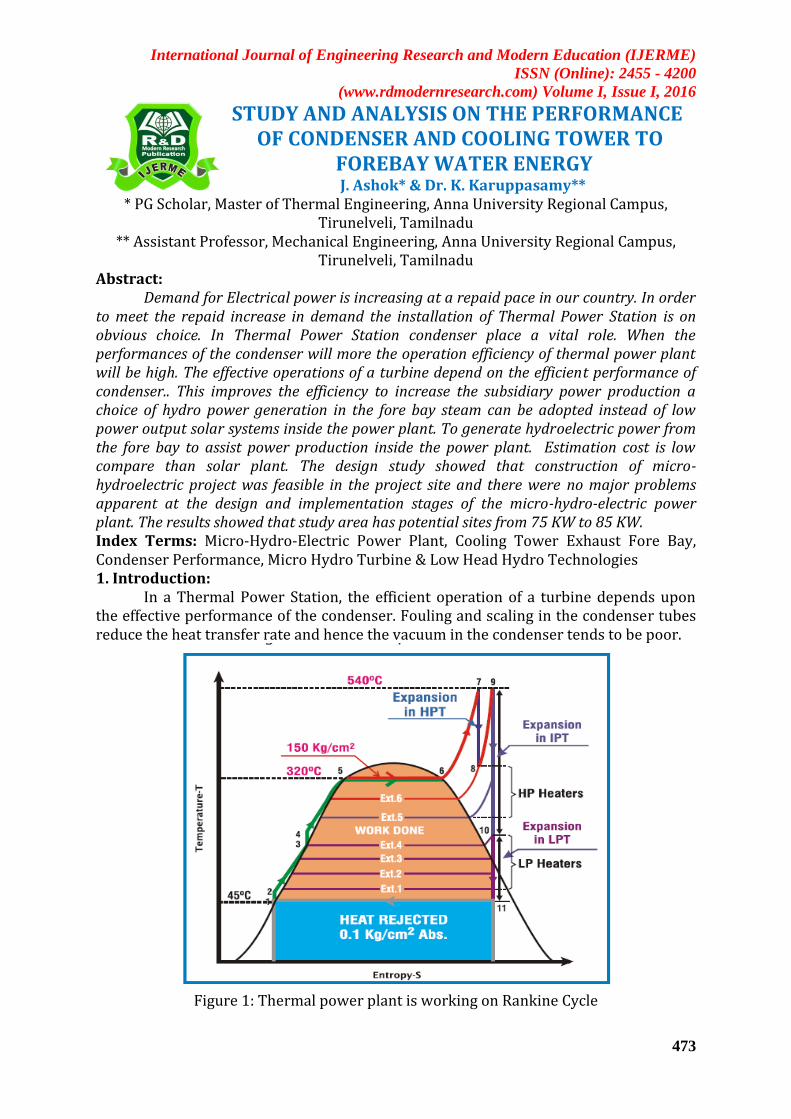
In a Thermal Power Station, the efficient operation of a turbine depends upon the effective performance of the condenser. Fouling and scaling in the condenser tubes reduce the heat transfer rate and hence the vacuum in the condenser tends to be poor.
Figure 1: Thermal power plant is working on Rankine Cycle
International Journal of Engineering Research and Modern Education (IJERME)
ISSN (Online): 2455 - 4200
(www.rdmodernresearch.com) Volume I, Issue I, 2016
474
Poor condenser performance is one of the major losses in efficiency of power plant. In practical the problems occurred by following reasons. Low cleanliness factor, Low pumping function, exhaust capacity, Low heat transfer co-efficient, Air leakage. After the steam has surrendered its useful heat to the turbine, it passes to the condenser. The work obtained by the turbine from the steam will increase as the back pressure is reduced, so it is always desirable to operate at the minimum economic back pressure, i.e. the condensate temperature should be as low as possible. If the condensing surface were infinite, the condensing temperature would equal the temperature of the inlet cooling water (CW). However, there is a practical limit and in practice the average temperature.
Of the condensate is about 15°C above the inlet temperature, but even so the size of condensing plant is considerable. For example, and a 660 MW unit the condenser may have 20,000X 25mm dia. Tubes, each 20 meters long. The reason for such a massive hear-transfer surface is apparent when it is realized that for a generator output of 660 MW about 780 MW of energy will be surrendered to the cooling water. 2. Objects of a Steam Condenser: The main object is to maintain low pressure (below atmospheric pressure).
Some extra work is obtained due to exhaust at a pressure lower than that the atmospheric. This improves the efficiency of the plant. Air inside the condenser should be pumped out continuously in order to maintain the vacuum.
The condensation of steam occurs in the range of 25°C to 38°C The secondary object is to supply pure feed water to the hot well, from where it
is pumped back to the boiler. Design Considerations of Micro-Hydroelectric Power Plants for Cooling Tower Outlet: 2.1 Flow Duration Curve: The choice of turbine type, size and speed is based on the net head and maximum water flow rate, which must be determined by the river or stream where the turbine shall be installed. 2.2 Flow Rate Measurement: Cooling tower base in capacity and circulating water flow rate to identify the slow rate. 2.3 Weir and Open Channel: In open channel foundation two requirements must be satisfied: The stability: channel is a rigid structure and do not permit deformations Channel does not support thrust or up lift pressure. The flow of water in open channel is considered uniform the water depth; area and velocity in every cross-section of the channel are constant. The energy gradient line, surface line and bottom channel line are parallel to each other. 2.4 Head Measurement: Velocity and gravity is used to find out the head. 2.5 Turbine Selection: Turbine power and speed is depending on the head and water flow rate. 2.6 Advantages of online Ball Cleaning System: Simple installation and maintenance, Thorough cleaning with uniform spread of sponge balls to both central and peripheral tubes, High reliability, Simple maintenance through continuous, automatic on-line cleaning, eliminating condenser downtime, Accurate control of the cleaning process: cleaning periods are customizable to maintain a high level of performance and minimize balls' wear, No heating of the condenser inlet caused by warm water re-injection, Single supplier for all units (both condensers and BOP cooling units) in the plant, automatic tube cleaning system (ATCS) is the most efficient and reliable automatic on-line solution for keeping shell and tube heat exchangers continuously clean and working at full capacity, chemical-free.

International Journal of Engineering Research and Modern Education (IJERME)
ISSN (Online): 2455 - 4200
(www.rdmodernresearch.com) Volume I, Issue I, 2016
475
2.7 Cooling Tower to Fore Bay Water Energy: There are a number of issues with recovering the energy from the stack exhaust of a cooling tower. Hydro turbine to design for not affecting the condenser performance. Micro-hydro: From 5kW up to 100 kW Pico-hydro: From 300 watts up to 5kW
Figure 2: DCS circulating water System
3. Performance Improvement Analysis for Condenser and Hydro Power Generation for Fore bay Water Energy: 3.1 Water Power is the Combination of Head and Flow: Consider typical hydro system water is diverted from a stream into a pipeline.
International Journal of Engineering Research and Modern Education (IJERME)
ISSN (Online): 2455 - 4200
(www.rdmodernresearch.com) Volume I, Issue I, 2016
476
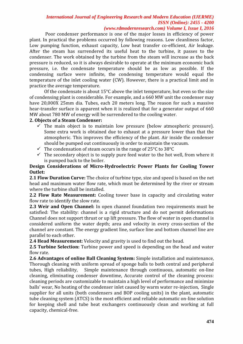
The vertical drop (HEAD) creates pressure at the bottom end of the pipeline. The pressurized water emerging from mouth of the fore bay creates the force that drives the turbine. More FLOW and more HEAD produce more power. Water is fed from stream/canal to the turbine by a closed pipe (penstock) through diversion works. The turbine in turn rotates the generator for electricity generation. These are the principles behind hydro electricity generation, which is applied in the cooling tower exit to fore bay stream in order to produce required power 3.1.1 Why Need of Hydro Power in NLC TPS-I EXPN: NLC has implemented Solar Electricity generating photocells for a sum of 10 lakh rupees which gives a power output of 3-5KW. In order to improvise the subsidiary power generation for running the auxiliary pumps in the power plant we came to a conclusion that power can be produced from the water flowing from cooling tower through the fore bay stream. This will help to produce power more than that of solar and will also help the organization to save money spent on low power resources. By constructing turbines according to the Head, Flow, Velocity of the water we can achieve a greater power output from the system. 3.1.2 Head: Head is created by the difference in elevation between the water intake and the turbine (m). 3.1.3 Flow: Flow is water quantity which flows through the stream (m3/sec). 3.1.4 Velocity: It is the ratio between distance and time of the water flow (m/sec). 3.2 Types of Hydro Turbines: Hydraulic Turbines: Impulse Turbines: hydraulic head is converted to kinetic energy before water enters the runner. 3.2.1 Pelton Turbines: Reaction Turbines: the runner is completely submerged and both pressure and velocity decrease from runner inlet to outlet. Francis turbines (radial or mixed flow) Axial turbines (axial flow): Kaplan (adjustable blade pitch), propeller (fixed blade pitch)
3.3 Head v Flow Hydro Turbine Selection Graph (Those that Work Very Well below 3m Head): Low Head Hydro Technologies: A range of technologies have been developed for low head higher flow sites
which tend to rely on ‘reaction’ rather than ‘impulse’ machines. Reaction machines develop torque by reacting to the weight and low pressure of
water and are lighter and cheaper to manufacture.

International Journal of Engineering Research and Modern Education (IJERME)
ISSN (Online): 2455 - 4200
(www.rdmodernresearch.com) Volume I, Issue I, 2016
477
Impulse machines develop torque from high pressure high velocity jets and therefore require casings (Pelton, Turgo, Ossberger Crossflow, Motor Pump Sets). Cross flow turbines are also suitable for low heads.
Reaction machines which are suitable for rivers and beck's include:- Traditional Waterwheels (overshot, midshot, undershot, backshot) – Propeller (Kaplan, Francis, compact axial, bulb type, stratflo, H&VAWT) – Archimedean Screw Turbines (old but proven technology) – Optimizations of these machine types to increase efficiencies and others:-
Zuppinger (German), Sagebien and Poncelot (French) Venturi (suction) effect to reduce net head or Siphon device (water to air) Floating wheel (much less efficient but no civil & low environmental effects) Other novel turbine devices (e.g. conveyor, gravity wheel, contra rotating) Darius & Gorlov turbines (developed for deep rivers and tidal streams/estuaries)
3.4 Type of Water Flow in Fore Bay Stream Run of River: No storage. The output is subject to instantaneous flow. Reliability of discharge and geological conditions Should be ensured.
3.5 Intake Structure: Assured water supply Suitable quality of water Control over supply of water Safety against flood
3.6 Type of Weirs: Trench weir Rock fill weirs Vertical drop weirs Concrete weir with sloping glacis Coanda weir Inflated weir/ Rubber dam
3.7 Construction Criteria of the Cooling Tower and Fore Bay System: Capacity= 33000 m3/hr. Inlet temperature=43°C , outlet temperature=34°C. Cooling range=9°C . Height=114.20m. Fore bay head – inclining with increase in depth from 3m-12m.
Figure 3: A model design of turbine blades Design of Rotating turbine mechanism Low
Head Hydro Technologies 10- 30kW, from 0.5- 1.5m head, Clean energy Production

International Journal of Engineering Research and Modern Education (IJERME)
ISSN (Online): 2455 - 4200
(www.rdmodernresearch.com) Volume I, Issue I, 2016
478
Figure 4: Clean and efficient hydro power generation
Figure 5: Zero and Ultra Low Head Devices
Modern efficient waterwheels – showing how old principles and modern technologies can work together (35 and 80kW courtesy of Hydrowatt) Water wheel produces the 55kw to 85kw In this type of turbine is used for fore bay to recover the water energy and to generate hydro power. 4. Results and Discussion: 4.1 Hydro Power Generation:
Low head hydro technologies are suitable one for fore bay water energy. Clean energy production Ltd providing new type of zero head and ultra head turbine which is used to construct the small hydro plant for cooling tower exhaust for bay water energy. Design of the ultra head hydro turbine having high efficiency for after implementation of the turbine efficiency is reaches 85% to 88%
Condenser performance of unit – 1 & 2 was analyzed and its performance indices were found to be averagely for the data collected Temperature rise in °C = 7.31052733°C Condenser Heat load =240891432kcal/hr Cleanliness factor =85 %
International Journal of Engineering Research and Modern Education (IJERME)
ISSN (Online): 2455 - 4200
(www.rdmodernresearch.com) Volume I, Issue I, 2016
479
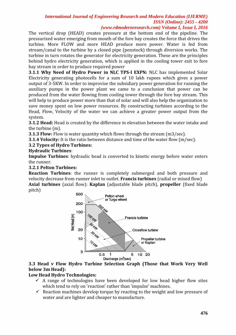
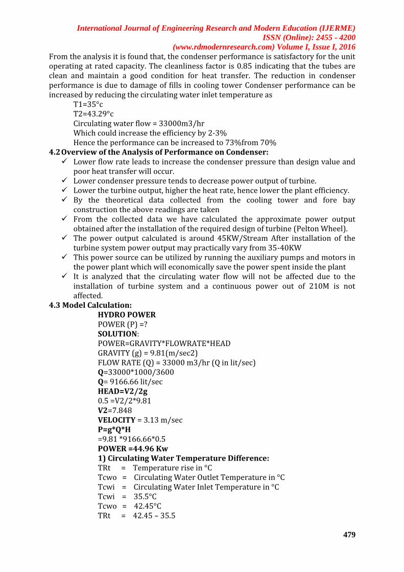
From the analysis it is found that, the condenser performance is satisfactory for the unit operating at rated capacity. The cleanliness factor is 0.85 indicating that the tubes are clean and maintain a good condition for heat transfer. The reduction in condenser performance is due to damage of fills in cooling tower Condenser performance can be increased by reducing the circulating water inlet temperature as
T1=35°c T2=43.29°c Circulating water flow = 33000m3/hr Which could increase the efficiency by 2-3% Hence the performance can be increased to 73%from 70%
4.2 Overview of the Analysis of Performance on Condenser: Lower flow rate leads to increase the condenser pressure than design value and
poor heat transfer will occur. Lower condenser pressure tends to decrease power output of turbine. Lower the turbine output, higher the heat rate, hence lower the plant efficiency. By the theoretical data collected from the cooling tower and fore bay
construction the above readings are taken From the collected data we have calculated the approximate power output
obtained after the installation of the required design of turbine (Pelton Wheel). The power output calculated is around 45KW/Stream After installation of the
turbine system power output may practically vary from 35-40KW This power source can be utilized by running the auxiliary pumps and motors in
the power plant which will economically save the power spent inside the plant It is analyzed that the circulating water flow will not be affected due to the
installation of turbine system and a continuous power out of 210M is not affected.
4.3 Model Calculation: HYDRO POWER POWER (P) =? SOLUTION: POWER=GRAVITY*FLOWRATE*HEAD GRAVITY (g) = 9.81(m/sec2) FLOW RATE (Q) = 33000 m3/hr (Q in lit/sec) Q=33000*1000/3600 Q= 9166.66 lit/sec HEAD=V2/2g 0.5 =V2/2*9.81 V2=7.848 VELOCITY = 3.13 m/sec P=g*Q*H =9.81 *9166.66*0.5 POWER =44.96 Kw 1) Circulating Water Temperature Difference: TRt = Temperature rise in °C Tcwo = Circulating Water Outlet Temperature in °C Tcwi = Circulating Water Inlet Temperature in °C Tcwi = 35.5°C Tcwo = 42.45°C TRt = 42.45 – 35.5
International Journal of Engineering Research and Modern Education (IJERME)
ISSN (Online): 2455 - 4200
(www.rdmodernresearch.com) Volume I, Issue I, 2016
480
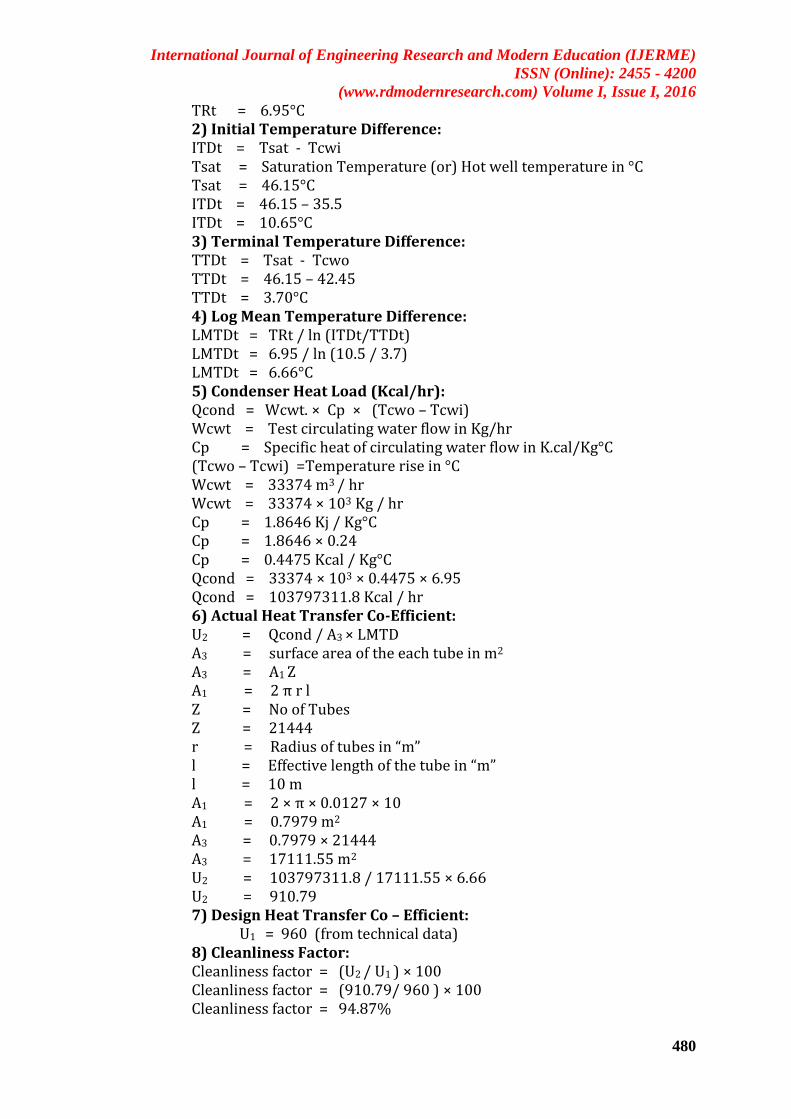
TRt = 6.95°C 2) Initial Temperature Difference: ITDt = Tsat - Tcwi Tsat = Saturation Temperature (or) Hot well temperature in °C Tsat = 46.15°C ITDt = 46.15 – 35.5 ITDt = 10.65°C 3) Terminal Temperature Difference: TTDt = Tsat - Tcwo TTDt = 46.15 – 42.45 TTDt = 3.70°C 4) Log Mean Temperature Difference: LMTDt = TRt / ln (ITDt/TTDt) LMTDt = 6.95 / ln (10.5 / 3.7) LMTDt = 6.66°C 5) Condenser Heat Load (Kcal/hr): Qcond = Wcwt. × Cp × (Tcwo – Tcwi) Wcwt = Test circulating water flow in Kg/hr Cp = Specific heat of circulating water flow in K.cal/Kg°C (Tcwo – Tcwi) =Temperature rise in °C Wcwt = 33374 m3 / hr Wcwt = 33374 × 103 Kg / hr Cp = 1.8646 Kj / Kg°C Cp = 1.8646 × 0.24 Cp = 0.4475 Kcal / Kg°C Qcond = 33374 × 103 × 0.4475 × 6.95 Qcond = 103797311.8 Kcal / hr 6) Actual Heat Transfer Co-Efficient: U2 = Qcond / A3 × LMTD A3 = surface area of the each tube in m2 A3 = A1 Z A1 = 2 π r l Z = No of Tubes Z = 21444 r = Radius of tubes in “m” l = Effective length of the tube in “m” l = 10 m A1 = 2 × π × 0.0127 × 10 A1 = 0.7979 m2 A3 = 0.7979 × 21444 A3 = 17111.55 m2 U2 = 103797311.8 / 17111.55 × 6.66 U2 = 910.79 7) Design Heat Transfer Co – Efficient:
U1 = 960 (from technical data) 8) Cleanliness Factor: Cleanliness factor = (U2 / U1 ) × 100 Cleanliness factor = (910.79/ 960 ) × 100 Cleanliness factor = 94.87%

International Journal of Engineering Research and Modern Education (IJERME)
ISSN (Online): 2455 - 4200
(www.rdmodernresearch.com) Volume I, Issue I, 2016
481
5. Conclusions: Result and theoretical calculation of this project mini hydro Plant designed successfully for cooling tower exhaust fore bay. Ultra head turbine blades having 3m length and light weight material are used. After implementation of the hydro turbine is not affecting the circulating water flow rate. Low Head sites are not being developed due to a lack of awareness of technologies, perceived costs and disproportionate regulation. In this mini hydro Potential is v high, Implementation v slow. Readings and Graphical result showing condenser performance will depends on the cooling tower water flow rate. Circulating water flow rate is low means condenser performance will be decreased. Condenser performance is most important for obtaining high efficiency of the thermal plant. Design and theoretical calculation of the zero head or ultra head turbine efficiency obtained for 85%. Hydro power upto 75 KW. Design of ultra head turbine is successfully done. 6. References:
1. Lorenzo Damiani, Alessandro Pini Prato. “Simulation of a Power Regulation System for Steam Power Plants” 2014 energy.
2. Bilal Abdullah Nasir “Design of Micro - Hydro - Electric Power Station” 2013International Journal of Engineering and Advanced Technology.
3. Livio De Santoli, Saverio Bergh, Daniele Brusch “A schematic framework to assess mini hydro potentials in the Italian Regional Energy and Environmental Plans”2015
4. Vladana N. Rajakovi Ognjanovi, Dragana Z.Zivojinovic, Branimir N. Grgur, Ljubinka V. Rajakovi, "Improvement of chemical control in the water-steam cycle of thermal powerplants", 2011 journal for applied thermal engineering.
5. Dragana Z. Zivojinovic , Ljubinka V. Rajakovic, “Application and validation of ion chromatography for the analysis of power plants water: Analysis of corrosive anions in conditioned water–steam cycles", 2011.
6. J. Ahmad, J. Purbolaksono, L.C. BengThermal “fatigue and corrosion fatigue in heat recovery area wall side tubes”, 2010.
7. Emre Akyuz, Metin Celik “A methodological extension to human reliability analysis for cargo tank cleaning operation on board chemical tanker ships”
8. Rong Cheng, Can Cheng, Guo-hua Liu , Xiang Zheng, Guanqing Li, Jie Li “Removing pentachlorophenol from water using a nanoscale zero-valent iron/H2O2 system”.