studio ii machining & mechactronics …singhose.marc.gatech.edu/courses/me2110...
TRANSCRIPT
ME 2110 – Studio II P a g e | 1 of 13 Ver. 2.0
Georgia Institute of Technology George W. Woodruff School of Mechanical Engineering
ME 2110 - Creative Decisions and Design Spring 2014
STUDIO II
MACHINING & MECHACTRONICS PROJECT: DRIVEN DOUBLE PENDULUM
In order to successfully design and build a product, you must understand the capabilities of the tools and supplies at your disposal. For example, you must understand how motors and sensors work. Furthermore, you must have knowledge of manufacturing processes, such as machining with milling machines, lathes, bandsaws, and drill presses. This project will help you develop an understanding of the supplies and manufacturing processes available to you in ME2110.
Pendulums are ubiquitous in engineering. Some useful pendulum systems include cranes, clocks, and the human walking gait. However, the dynamics of pendulum systems become complicated as the number of links is increased. Such systems may exhibit nonlinear effects such as bifurcations and chaos. Your goal is to build a machine to demonstrate some of the nonlinear effects associated with pendulum systems.
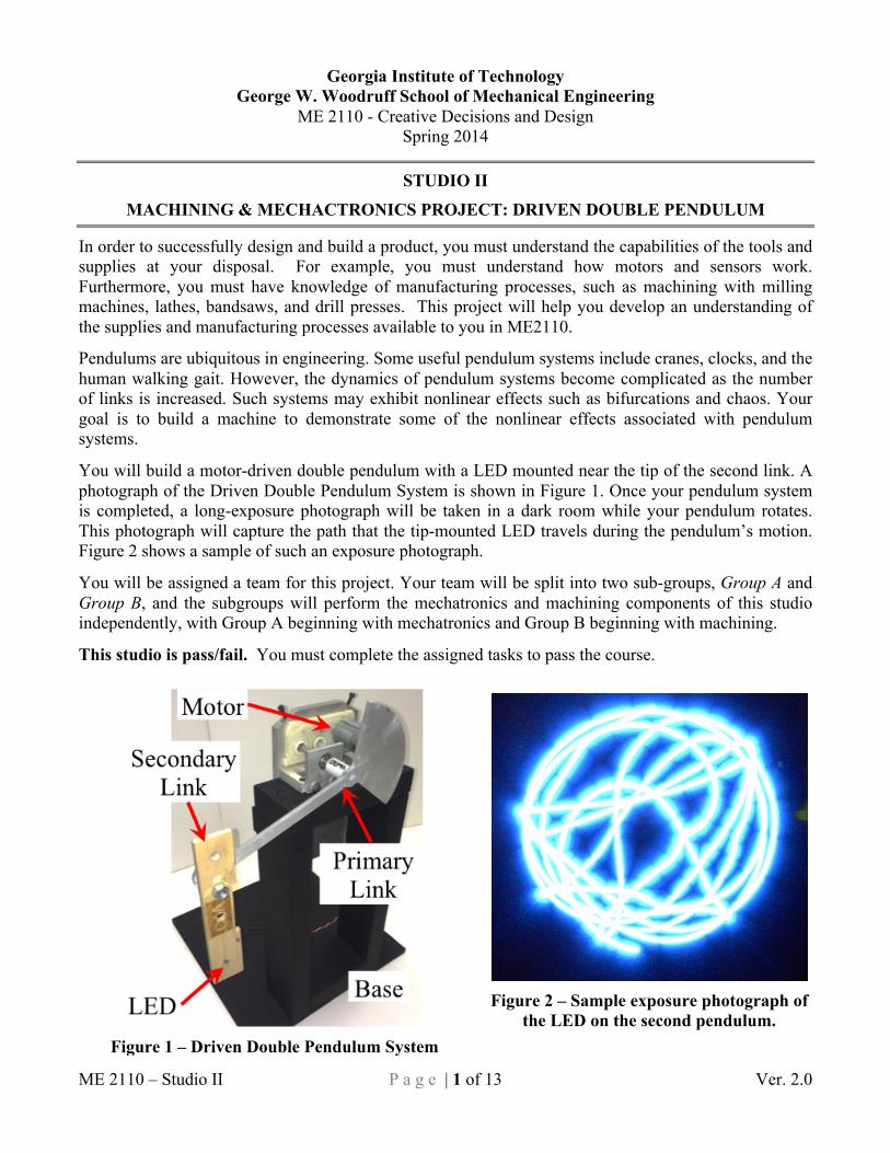
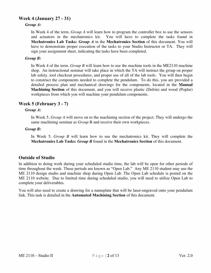
You will build a motor-driven double pendulum with a LED mounted near the tip of the second link. A photograph of the Driven Double Pendulum System is shown in Figure 1. Once your pendulum system is completed, a long-exposure photograph will be taken in a dark room while your pendulum rotates. This photograph will capture the path that the tip-mounted LED travels during the pendulum’s motion. Figure 2 shows a sample of such an exposure photograph.
You will be assigned a team for this project. Your team will be split into two sub-groups, Group A and Group B, and the subgroups will perform the mechatronics and machining components of this studio independently, with Group A beginning with mechatronics and Group B beginning with machining.
This studio is pass/fail. You must complete the assigned tasks to pass the course.
Figure 1 – Driven Double Pendulum System
Figure 2 – Sample exposure photograph of
the LED on the second pendulum.
ME 2110 – Studio II P a g e | 2 of 13 Ver. 2.0
Week 4 (January 27 - 31) Group A:
In Week 4 of the term, Group A will learn how to program the controller box to use the sensors and actuators in the mechatronics kit. You will have to complete the tasks found in Mechatronics Lab Tasks: Group A in the Mechatronics Section of this document. You will have to demonstrate proper execution of the tasks to your Studio Instructor or TA. They will sign your assignment sheet, indicating the tasks have been completed.
Group B:
In Week 4 of the term, Group B will learn how to use the machine tools in the ME2110 machine shop. An instructional seminar will take place in which the TA will instruct the group on proper lab safety, tool checkout procedures, and proper use of all of the lab tools. You will then begin to construct the components needed to complete the pendulum. To do this, you are provided a detailed process plan and mechanical drawings for the components, located in the Manual Machining Section of this document, and you will receive plastic (Delrin) and wood (Poplar) workpieces from which you will machine your pendulum components.
Week 5 (February 3 - 7) Group A:
In Week 5, Group A will move on to the machining section of the project. They will undergo the same machining seminar as Group B and receive their own workpieces.
Group B:
In Week 5, Group B will learn how to use the mechatronics kit. They will complete the Mechatronics Lab Tasks: Group B found in the Mechatronics Section of this document.
Outside of Studio In addition to doing work during your scheduled studio time, the lab will be open for other periods of time throughout the week. These periods are known as “Open Lab.” Any ME 2110 student may use the ME 2110 design studio and machine shop during Open Lab. The Open Lab schedule is posted on the ME 2110 website. Due to limited time during scheduled studio, you will need to utilize Open Lab to complete your deliverables.
You will also need to create a drawing for a nameplate that will be laser-engraved onto your pendulum link. This task is detailed in the Automated Machining Section of this document.

ME 2110 – Studio II P a g e | 3 of 13 Ver. 2.0
Week 6 (February 10 - 14) By Week 6 of the semester, you will need to have completed the pendulum link and nameplate drawing. You will write you initials on the back of the pendulum link and turn it in to your TA. Before studio, you must email a nameplate drawing file to your TA. The rest of this week will give you time to finish the Pendulum Coupler and mechatronics exercises.
Week 7 in Studio (February 17 - 21) – Machining Contest By Week 7, you will have completed your pendulum components and gained sufficient knowledge of the operation of the mechatronics kit. You will use your pendulum components to compete against other students in your studio to determine who can create the “best” exposure photo trace of their pendulum. The instructor and TA will nominate the top three photos, and the studio section will vote to decide which photo wins.
You will get three opportunities to run your pendulum for 10 seconds, during which time an 8-second exposure photo will be taken using an iPad. You must complete the pendulum assembly using the Coupler and Secondary Pendulum Link that you machined during this studio. You can mount your Secondary Pendulum Link to the Primary Link pivot using any of the three holes you drilled.
A high-torque, low-speed DC motor will drive the pendulum system. The speed of this DC motor may be controlled using the controller box. Each student will need to program his or her own 10-second speed profile to run on the team’s controller box. Your controller box will then be connected to the motor. The program should begin executing your motor speed profile when a switch is pressed, and stop the motor after 10 seconds. The pendulum system will be available for testing in the machine shop throughout the duration of this studio. You should practice several times and test your code to determine what sort of speed profiles and pivot hole locations create the most interesting motion of the LED.
Deliverables Table 1 shows the deliverable schedule for this project.
Table 1 - Deliverables for Each Individual During Weeks 5 - 7.
Group A Group B
Week 5 Deliverables, due at the Beginning of studio
(February 3 - 7)
-3 of 5 completed and signed Mechatronics Lab Tasks: Group A
- Secondary Pendulum Link
- 1 Drawing for a Nameplate
Week 6 Deliverables, due at the Beginning of studio
(February 10 - 14)
- Secondary Pendulum Link
- 1 Drawing for a Nameplate
- Pendulum Coupler
- 3 of 5 completed and signed Mechatronics Lab Tasks: Group B
Week 7 Deliverables, due at the Beginning of studio
(February 17 - 21)
- Pendulum Coupler
- All 5 completed and signed Mechatronics Lab Tasks: Group A
- All 5 completed and signed Mechatronics Lab Tasks: Group B
ME 2110 – Studio II P a g e | 4 of 13 Ver. 2.0
Mechatronics Section This lab will provide experience with integrating electrical, mechanical, and pneumatic systems. The lab comprises two sections performed over two weeks. During the first week, Group A will complete one part of the lab, labeled "Mechatronics Lab Tasks: Group A," the second part will be completed by Group B during the second week. Although the programming style will not be graded, the code written during these two labs should be helpful in developing the code for the final project. Therefore, it is important to program using standard structure and commenting practices so that the program will be easy to follow when used as a reference later in the semester. The suggested format for your code is: • Constants Table • Program Variables • Main Program • Subroutines Before attempting to perform these programming tasks, read through the Mechatronics and Pneumatics Manual which is available on the course website. The manual should provide a good background to the layout of the controller box and how to implement the electro-mechanical-pneumatic components in a design. Note that there are two versions of this manual: one for the ME2110 Basic Stamp Controller Box and another for the National Instruments myRIO Controller. Be sure to use the manual that is written for your controller.
This project has two checkpoints for each Group. Group A must have 3 of the 5 Group A exercises completed by Week 5. Group B must have 3 of the 5 Group B exercises completed by Week 6. Both Groups must have finished all 5 of their assigned exercises by Week 7 at the beginning of studio. At the time of each checkpoint, each student is responsible for showing progress through the assignment as indicated by a signed task checklist. The task for Group A and Group B, and the associated checklists, are provided on the subsequent two pages. After each task is completed, the operation must be successfully demonstrated to either the section instructor or the section TA. The instructor or TA will initial the checklist confirming that the team has successfully completed that task element. Remember that each individual needs a separately signed checklist. Feel free to ask the professor, TA, or peers for help in completion of this assignment, however each student in the team must be prepared to answer questions about the program before the instructor or TA will initial the checklist.
ME 2110 – Studio II P a g e | 5 of 13 Ver. 2.0
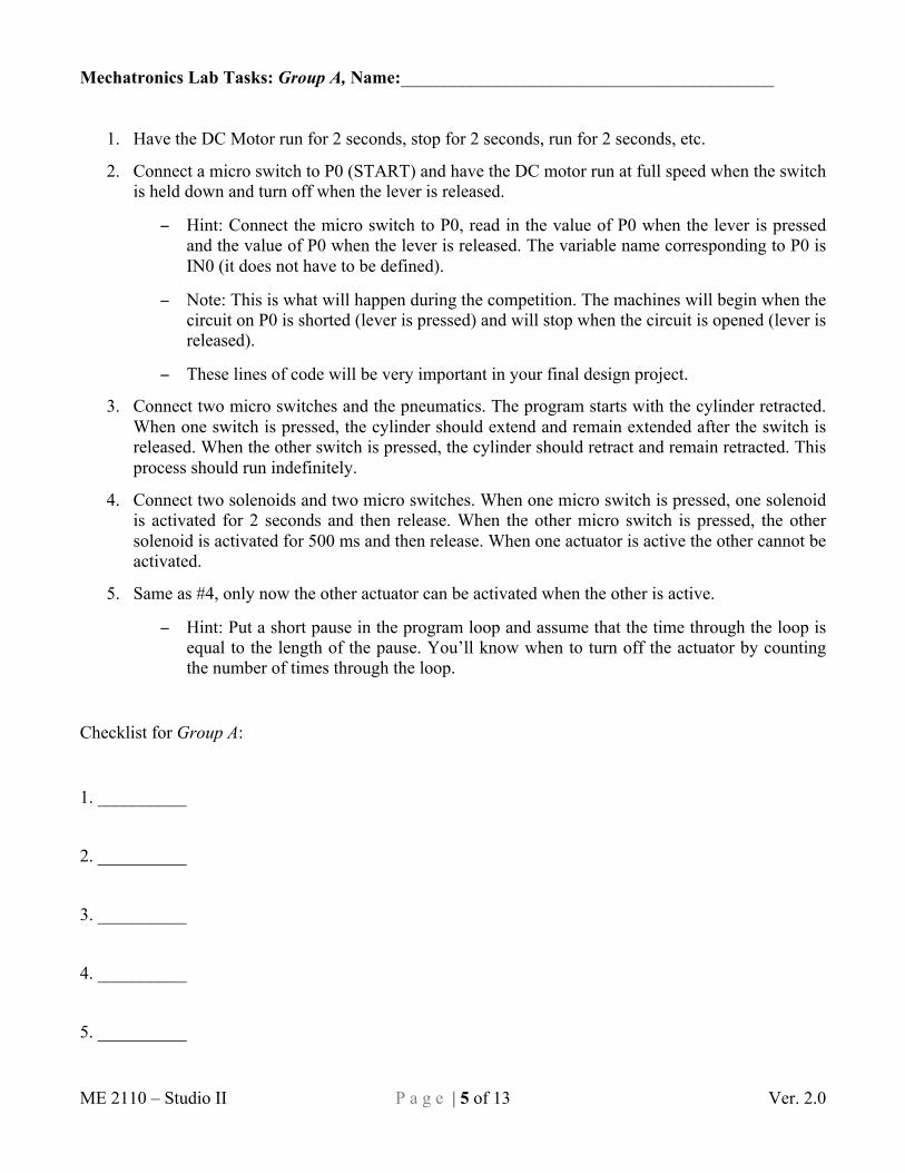
Mechatronics Lab Tasks: Group A, Name:__________________________________________
1. Have the DC Motor run for 2 seconds, stop for 2 seconds, run for 2 seconds, etc.
2. Connect a micro switch to P0 (START) and have the DC motor run at full speed when the switch is held down and turn off when the lever is released.
− Hint: Connect the micro switch to P0, read in the value of P0 when the lever is pressed and the value of P0 when the lever is released. The variable name corresponding to P0 is IN0 (it does not have to be defined).
− Note: This is what will happen during the competition. The machines will begin when the circuit on P0 is shorted (lever is pressed) and will stop when the circuit is opened (lever is released).
− These lines of code will be very important in your final design project.
3. Connect two micro switches and the pneumatics. The program starts with the cylinder retracted. When one switch is pressed, the cylinder should extend and remain extended after the switch is released. When the other switch is pressed, the cylinder should retract and remain retracted. This process should run indefinitely.
4. Connect two solenoids and two micro switches. When one micro switch is pressed, one solenoid is activated for 2 seconds and then release. When the other micro switch is pressed, the other solenoid is activated for 500 ms and then release. When one actuator is active the other cannot be activated.
5. Same as #4, only now the other actuator can be activated when the other is active.
− Hint: Put a short pause in the program loop and assume that the time through the loop is equal to the length of the pause. You’ll know when to turn off the actuator by counting the number of times through the loop.
Checklist for Group A:
1. __________
2. __________
3. __________
4. __________
5. __________
ME 2110 – Studio II P a g e | 6 of 13 Ver. 2.0
Mechatronics Lab Tasks: Group B, Name:__________________________________________
1. Connect both DC motors. Make them run clockwise for five seconds, stop for 2.5 seconds, run counter-clockwise for five seconds, and then stop for 2.5 seconds. Repeat this sequence five times.
2. Perform the same act as #1, but always have the two DC motors rotating in opposite directions.
3. Connect the IR distance sensor and one DC motor. Have the motor run if the reading is greater than 128 and have the motor stop if the reading is less than 127. Put a two-second pause between distance sensor readings.
4. Connect the encoder and have the DC motor run at full speed when the encoder is being rotated and stopped when it is not being rotated.
5. Connect the encoder and the pneumatics. When the encoder is rotated 5 complete revolutions, the actuator should extend and remain extended until the encoder is rotated 3 complete revolutions. The cylinder should only extend 4 times and then remain retracted regardless of how many times the encoder is rotated.
Checklist for Group B:
1. __________
2. __________
3. __________
4. __________
5. __________
ME 2110 – Studio II P a g e | 7 of 13 Ver. 2.0
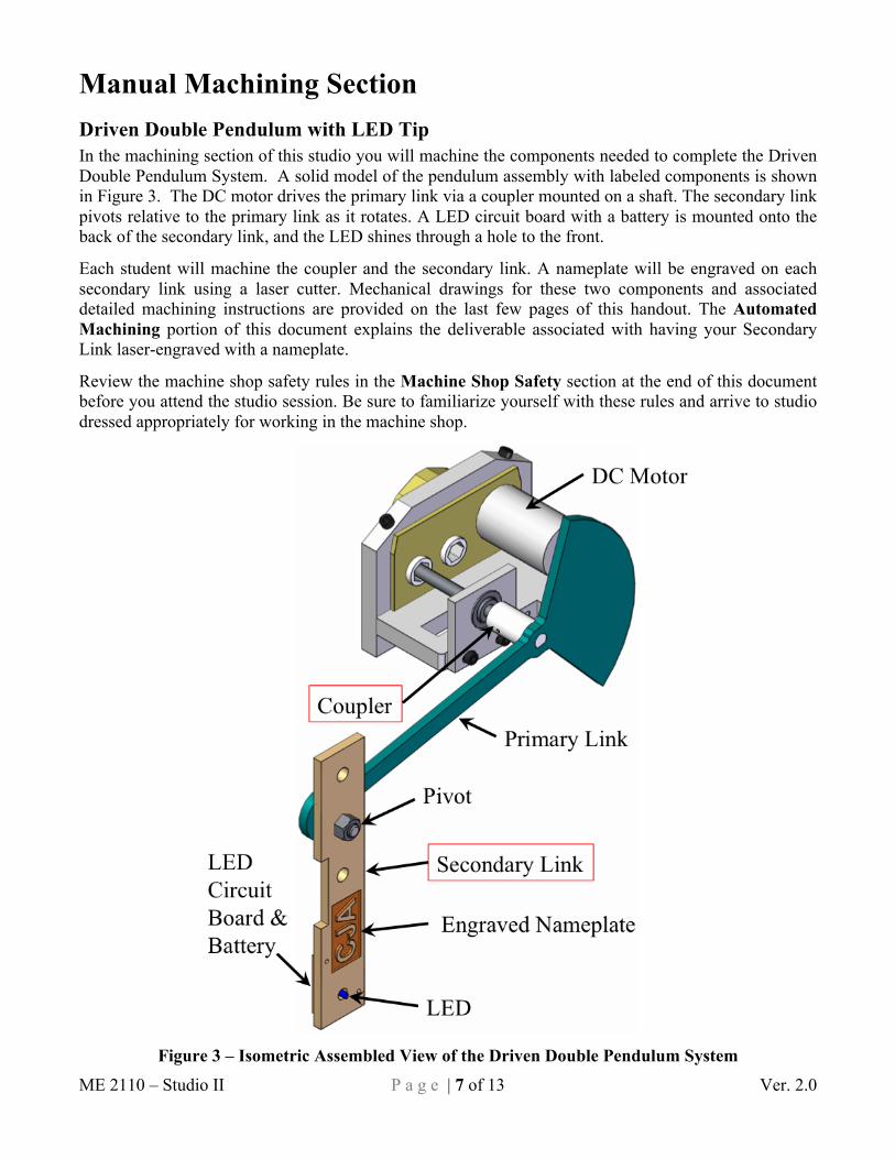
Manual Machining Section Driven Double Pendulum with LED Tip In the machining section of this studio you will machine the components needed to complete the Driven Double Pendulum System. A solid model of the pendulum assembly with labeled components is shown in Figure 3. The DC motor drives the primary link via a coupler mounted on a shaft. The secondary link pivots relative to the primary link as it rotates. A LED circuit board with a battery is mounted onto the back of the secondary link, and the LED shines through a hole to the front.
Each student will machine the coupler and the secondary link. A nameplate will be engraved on each secondary link using a laser cutter. Mechanical drawings for these two components and associated detailed machining instructions are provided on the last few pages of this handout. The Automated Machining portion of this document explains the deliverable associated with having your Secondary Link laser-engraved with a nameplate.
Review the machine shop safety rules in the Machine Shop Safety section at the end of this document before you attend the studio session. Be sure to familiarize yourself with these rules and arrive to studio dressed appropriately for working in the machine shop.
Figure 3 – Isometric Assembled View of the Driven Double Pendulum System
ME 2110 – Studio II P a g e | 8 of 13 Ver. 2.0
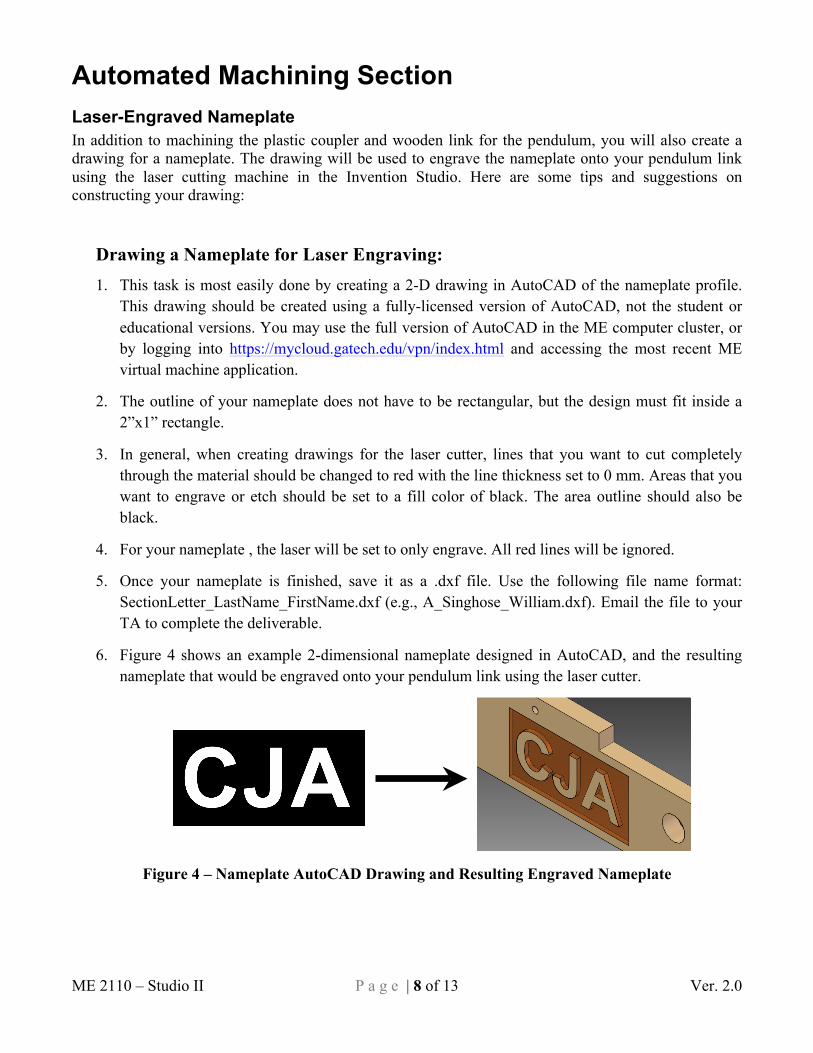
Automated Machining Section Laser-Engraved Nameplate In addition to machining the plastic coupler and wooden link for the pendulum, you will also create a drawing for a nameplate. The drawing will be used to engrave the nameplate onto your pendulum link using the laser cutting machine in the Invention Studio. Here are some tips and suggestions on constructing your drawing:
Drawing a Nameplate for Laser Engraving: 1. This task is most easily done by creating a 2-D drawing in AutoCAD of the nameplate profile.
This drawing should be created using a fully-licensed version of AutoCAD, not the student or educational versions. You may use the full version of AutoCAD in the ME computer cluster, or by logging into https://mycloud.gatech.edu/vpn/index.html and accessing the most recent ME virtual machine application.
2. The outline of your nameplate does not have to be rectangular, but the design must fit inside a 2”x1” rectangle.
3. In general, when creating drawings for the laser cutter, lines that you want to cut completely through the material should be changed to red with the line thickness set to 0 mm. Areas that you want to engrave or etch should be set to a fill color of black. The area outline should also be black.
4. For your nameplate , the laser will be set to only engrave. All red lines will be ignored.
5. Once your nameplate is finished, save it as a .dxf file. Use the following file name format: SectionLetter_LastName_FirstName.dxf (e.g., A_Singhose_William.dxf). Email the file to your TA to complete the deliverable.
6. Figure 4 shows an example 2-dimensional nameplate designed in AutoCAD, and the resulting nameplate that would be engraved onto your pendulum link using the laser cutter.
Figure 4 – Nameplate AutoCAD Drawing and Resulting Engraved Nameplate
ME 2110 – Studio II P a g e | 9 of 13 Ver. 2.0
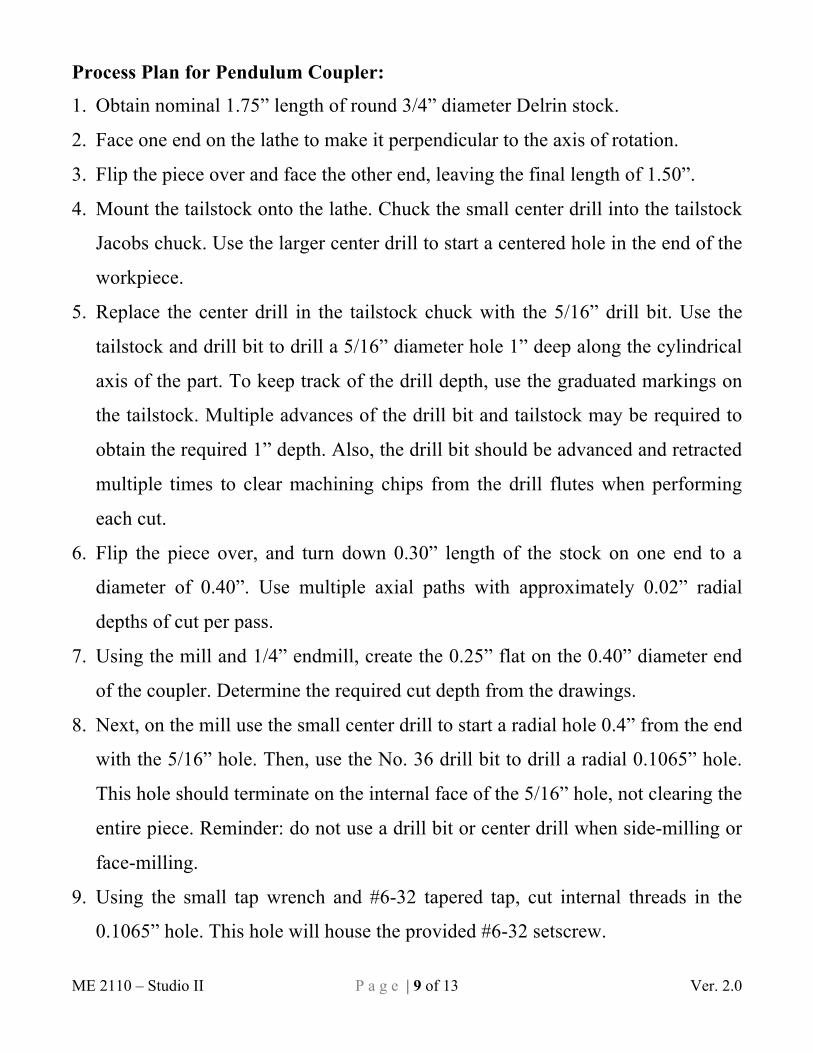
Process Plan for Pendulum Coupler:
1. Obtain nominal 1.75” length of round 3/4” diameter Delrin stock.
2. Face one end on the lathe to make it perpendicular to the axis of rotation.
3. Flip the piece over and face the other end, leaving the final length of 1.50”.
4. Mount the tailstock onto the lathe. Chuck the small center drill into the tailstock
Jacobs chuck. Use the larger center drill to start a centered hole in the end of the
workpiece.
5. Replace the center drill in the tailstock chuck with the 5/16” drill bit. Use the
tailstock and drill bit to drill a 5/16” diameter hole 1” deep along the cylindrical
axis of the part. To keep track of the drill depth, use the graduated markings on
the tailstock. Multiple advances of the drill bit and tailstock may be required to
obtain the required 1” depth. Also, the drill bit should be advanced and retracted
multiple times to clear machining chips from the drill flutes when performing
each cut.
6. Flip the piece over, and turn down 0.30” length of the stock on one end to a
diameter of 0.40”. Use multiple axial paths with approximately 0.02” radial
depths of cut per pass.
7. Using the mill and 1/4” endmill, create the 0.25” flat on the 0.40” diameter end
of the coupler. Determine the required cut depth from the drawings.
8. Next, on the mill use the small center drill to start a radial hole 0.4” from the end
with the 5/16” hole. Then, use the No. 36 drill bit to drill a radial 0.1065” hole.
This hole should terminate on the internal face of the 5/16” hole, not clearing the
entire piece. Reminder: do not use a drill bit or center drill when side-milling or
face-milling.
9. Using the small tap wrench and #6-32 tapered tap, cut internal threads in the
0.1065” hole. This hole will house the provided #6-32 setscrew.

ME 2110 – Studio II P a g e | 10 of 13 Ver. 2.0
Process Plan for Secondary Pendulum Link:
1. Obtain nominal 9.5”x1.5” piece of 1/4”-thick poplar.
2. Using the bandsaw, cut the piece down to the desired 8” length.
3. Using the mill, create the 2”-long slot on one side of the part. Orient the piece
with one of the long, narrow sides facing upwards when performing this milling
operation.
4. Using the large drill press and size W drill bit, drill up to three 0.386” holes.
These holes should be within the 3.5”x1” area permitted for holes indicated by
the dashed rectangle in the secondary pendulum link part drawing.
5. Drill the 5/16” and 0.1065” holes using the LED circuit board drilling template,
a drill driver, and the 5/16” and No. 36 drill bits, respectively. A drill driver and
the drilling template may be checked out from the TA on duty using your
Buzzcard. Before drilling, clamp the part to a workbench, then clamp the
drilling template on top of the part in the correct location and orientation. Make
sure there is also some backing material under the part so you do not drill into
the workbench.
6. Using the small tap wrench and #6-32 tapered tap, cut internal threads in the two
0.1065” holes. These threaded holes will be used to mount the LED circuit
board to the back of pendulum link. The LED will then shine through the 5/16”
hole to the front face of the link.
7. Turn in the nearly-complete secondary pendulum link to your TA. Your TA will
then engrave your submitted 2”x1” nameplate drawing onto the pendulum link
using a laser cutter.

ME 2110 – Studio II P a g e | 11 of 13 Ver. 2.0
DRAW
N
DIM
ENSI
ONS
ARE
IN IN
CHES
TWO
PLA
CE D
ECIM
AL ±
0.01
THRE
E PL
ACE
DECI
MAL
±0.
005
UNL
ESS
OTH
ERW
ISE
INDI
CATE
D
C. A
dam
s12
/11/
13M
E 21
10Ge
orgi
a Te
chTI
TLE
SIZE A
DWG
NO
SHEE
T 1
OF
2
MAT
ERIA
L
0.25
0.30
1.50
0.35
6+0
.005
-0.0
000.
40+0
.01
-0.0
0O
AA
DRIL
L O
5/16
` 1
0.4
DRIL
L O
No.
36
THRU
TAP
#6-
32 U
NC T
HRU
0.75
O NOM
INAL
SECT
ION
A-A
Coupler
Whi
te D
elrin
Pla
stic
SCAL
E: 2
:1

ME 2110 – Studio II P a g e | 12 of 13 Ver. 2.0
DRAW
N
DIM
ENSI
ONS
ARE
IN IN
CHES
TWO
PLA
CE D
ECIM
AL ±
0.01
THRE
E PL
ACE
DECI
MAL
±0.
005
UNL
ESS
OTH
ERW
ISE
INDI
CATE
D
C. A
dam
s12
/11/
13M
E 21
10Ge
orgi
a Te
chTI
TLE
SIZE A
DWG
NO
SHEE
T 2
OF
2
MAT
ERIA
L
SCAL
E: 1
:1
Seco
ndar
y Pe
ndul
um L
ink
1/4"
Pop
lar
(or
sim
ilar
woo
d)
1.00
2.00
8.00
0±0
.062
1.5 NOM
INAL
4.50
0.12
2.00
3.00
0.75
Engr
aved
Nam
epla
te(S
ampl
e Sh
own)
0.69
DRIL
L O
5/16
THR
U
3.5
1.0
B
DETA
IL B
1.107
0.20
0.50
1.437
2x D
RILL
O N
o. 3
6 TH
RUTA
P #
6-32
UNC
THR
U
0.25
0.5
3x D
RILL
O W
THR
ULO
CATE
D W
HOLL
Y W
ITHI
N BO
UND
ARY
0.25
ME 2110 – Studio II P a g e | 13 of 13 Ver. 2.0
MACHINE SHOP SAFETY
ALWAYS WEAR SAFETY GLASSES • Even when you are not working on a machine, you must wear safety glasses. A chip from a machine someone else is working on could fly into your eye.
CLOTHING, JEWELRY, AND HAIR • Wear long pants (to your shoes). • Wear short sleeves or roll up sleeves. • Wear closed toe shoes and socks. • Remove all jewelry - watches, bracelets, rings, necklaces, dangling earrings, etc. • Long hair or beards must be tied back.
•If your hair is caught in spinning machinery, it will be pulled out if you are lucky. If you are unlucky, you will be pulled into the machine.
• No ties, scarves, and dangling clothes. SAFE CONDUCT IN THE MACHINE SHOP • Be aware of what's going on around you.
•For example, be careful not to bump into someone while they're cutting with the bandsaw (they could lose a finger!).
• Concentrate on what you're doing. If you get tired, leave. • Don't hurry. If you catch yourself rushing, slow down. • Don't let someone else talk you into doing something dangerous. • Don't attempt to measure a part that's moving. • No fooling around. MACHINING • Follow directions. If you don’t know how to do something, ask. • Before you start the machine:
• Study the machine. Know which parts move, which are stationary, and which are sharp. • Double check that your workpiece is securely held. • Remove chuck keys and wrenches.
• Don't rush speeds and feeds. You'll end up damaging your part, the tools, and maybe the machine itself. • Listen to the machine/tool. If something doesn't sound right, turn the machine off. • Do not leave machines running unattended. • Clean up machines after you use them: a dirty machine is unsafe and uncomfortable to work on. • Do not use compressed air to blow machines clean. This endangers people's eyes and can force dirt into machine bearings. • Report all broken or non-working machines.
VIOLATIONS OF THESE RULES WILL RESULT IN IMMEDIATE EJECTION FROM THE MACHINE SHOP.