studio air final journal
DESCRIPTION
ÂTRANSCRIPT
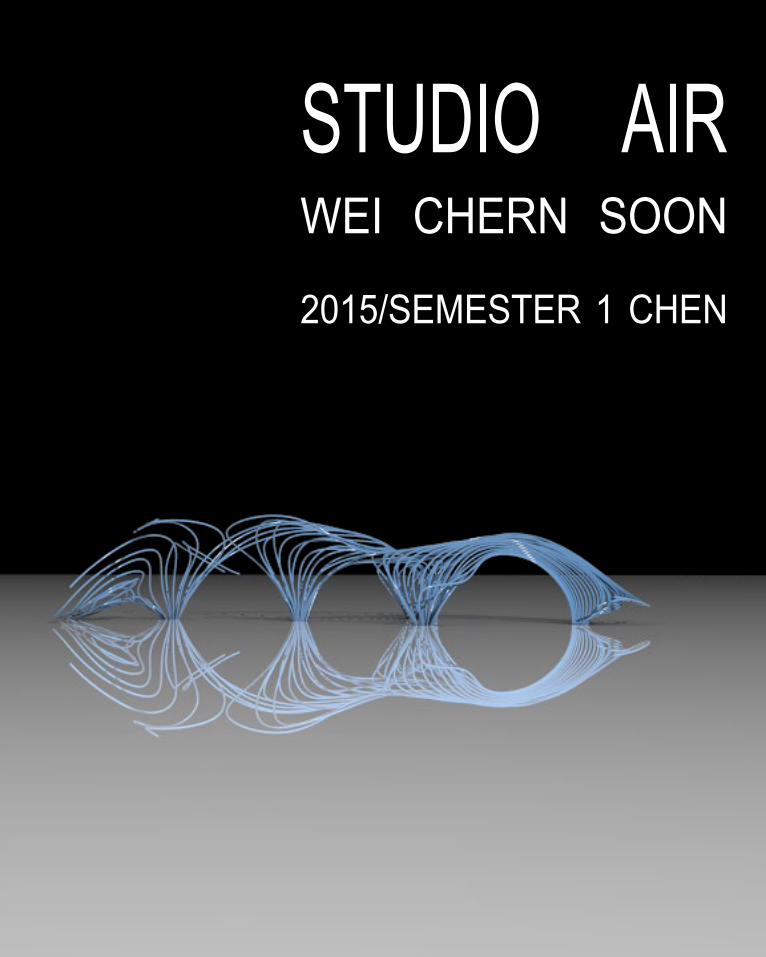
STUDIO AIRWEI CHERN SOON
2015/SEMESTER 1 CHEN
A great building must begin with the unmeasurable, must go through measurable means when it is being designed and in the end must be unmeasurable.
-----------LOUIS KAHN
CONTENT
INTRODUCTION4
A1. DESIGN FUTURING9
A2. DESIGN COMPUTATION13
A3. COMPOSITION/GENERATION17
CONCLUSION18
LEARNING OUTCOME19
APPENDIX & ALGORITHM SKETCHBOOK21
REFERENCES23
INTRODUCTION
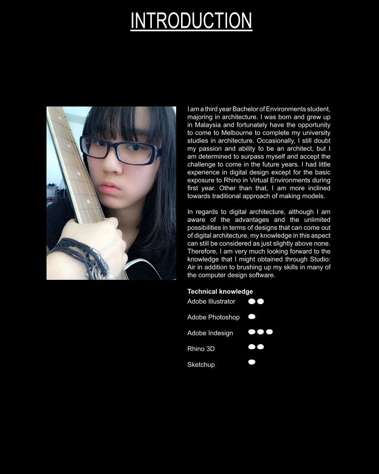
I am a third year Bachelor of Environments student, majoring in architecture. I was born and grew up in Malaysia and fortunately have the opportunity to come to Melbourne to complete my university studies in architecture. Occasionally, I still doubt my passion and ability to be an architect, but I am determined to surpass myself and accept the challenge to come in the future years. I had little experience in digital design except for the basic exposure to Rhino in Virtual Environments during first year. Other than that, I am more inclined towards traditional approach of making models.
In regards to digital architecture, although I am aware of the advantages and the unlimited possibilities in terms of designs that can come out of digital architecture, my knowledge in this aspect can still be considered as just slightly above none. Therefore, I am very much looking forward to the knowledge that I might obtained through Studio: Air in addition to brushing up my skills in many of the computer design software.
Technical knowledgeAdobe Illustrator
Adobe Photoshop
Adobe Indesign
Rhino 3D
Sketchup
CONCEPTUALISATION
PAGE 5
ACONCEPTUALISATION
A1: DESIGN FUTURINGTHE EDEN PROJECT
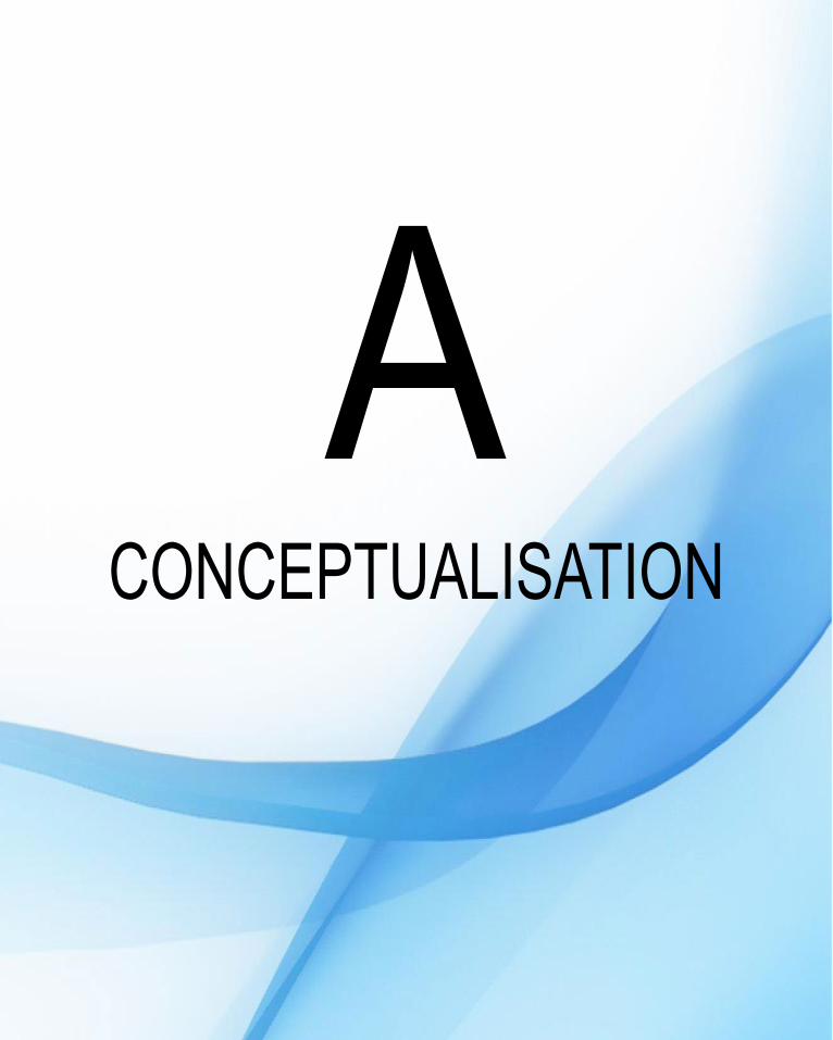
The Eden project is a giant, multi-domed greenhouse which houses plants from around the globe led by architect Nicholas Grimshaw and Partners also horticulture engineer, Tim Smitt.1 To date, it still functions to educate the public about the importance of relationship between plants, people and resources, with the aim of achieving a sustainable environment in the future through the study of plants.2
PROJECT CONTRIBUTION
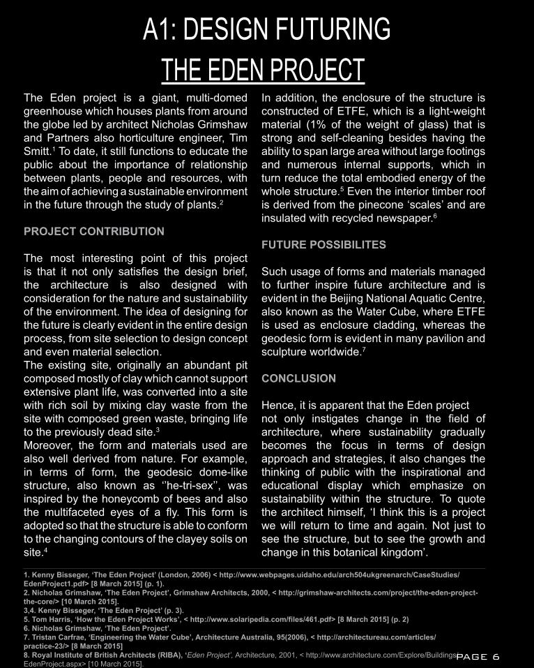
The most interesting point of this project is that it not only satisfies the design brief, the architecture is also designed with consideration for the nature and sustainability of the environment. The idea of designing for the future is clearly evident in the entire design process, from site selection to design concept and even material selection. The existing site, originally an abundant pit composed mostly of clay which cannot support extensive plant life, was converted into a site with rich soil by mixing clay waste from the site with composed green waste, bringing life to the previously dead site.3
Moreover, the form and materials used are also well derived from nature. For example, in terms of form, the geodesic dome-like structure, also known as ‘’he-tri-sex’’, was inspired by the honeycomb of bees and also the multifaceted eyes of a fly. This form is adopted so that the structure is able to conform to the changing contours of the clayey soils on site.4
In addition, the enclosure of the structure is constructed of ETFE, which is a light-weight material (1% of the weight of glass) that is strong and self-cleaning besides having the ability to span large area without large footings and numerous internal supports, which in turn reduce the total embodied energy of the whole structure.5 Even the interior timber roof is derived from the pinecone ‘scales’ and are insulated with recycled newspaper.6
FUTURE POSSIBILITES
Such usage of forms and materials managed to further inspire future architecture and is evident in the Beijing National Aquatic Centre, also known as the Water Cube, where ETFE is used as enclosure cladding, whereas the geodesic form is evident in many pavilion and sculpture worldwide.7
CONCLUSION
Hence, it is apparent that the Eden project not only instigates change in the field of architecture, where sustainability gradually becomes the focus in terms of design approach and strategies, it also changes the thinking of public with the inspirational and educational display which emphasize on sustainability within the structure. To quote the architect himself, ‘I think this is a project we will return to time and again. Not just to see the structure, but to see the growth and change in this botanical kingdom’.
1. Kenny Bisseger, ‘The Eden Project’ (London, 2006) < http://www.webpages.uidaho.edu/arch504ukgreenarch/CaseStudies/EdenProject1.pdf> [8 March 2015] (p. 1).2. Nicholas Grimshaw, ‘The Eden Project’, Grimshaw Architects, 2000, < http://grimshaw-architects.com/project/the-eden-project-the-core/> [10 March 2015].3,4. Kenny Bisseger, ‘The Eden Project’ (p. 3).5. Tom Harris, ‘How the Eden Project Works’, < http://www.solaripedia.com/files/461.pdf> [8 March 2015] (p. 2)6. Nicholas Grimshaw, ‘The Eden Project’. 7. Tristan Carfrae, ‘Engineering the Water Cube’, Architecture Australia, 95(2006), < http://architectureau.com/articles/practice-23/> [8 March 2015]8. Royal Institute of British Architects (RIBA), ‘Eden Project’, Architecture, 2001, < http://www.architecture.com/Explore/Buildings/EdenProject.aspx> [10 March 2015].
PAGE 6
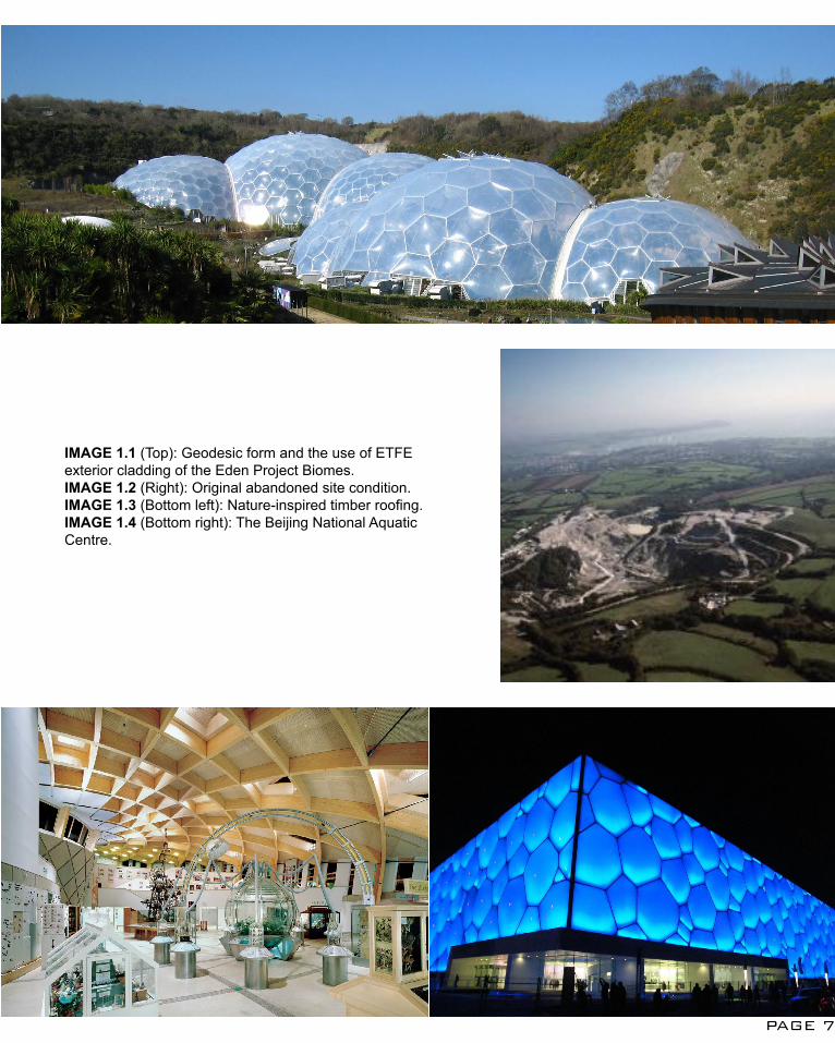
IMAGE 1.1 (Top): Geodesic form and the use of ETFE exterior cladding of the Eden Project Biomes.IMAGE 1.2 (Right): Original abandoned site condition.IMAGE 1.3 (Bottom left): Nature-inspired timber roofing.IMAGE 1.4 (Bottom right): The Beijing National Aquatic Centre.
PAGE 7
A1: DESIGN FUTURINGSERPENTINE PAVILION
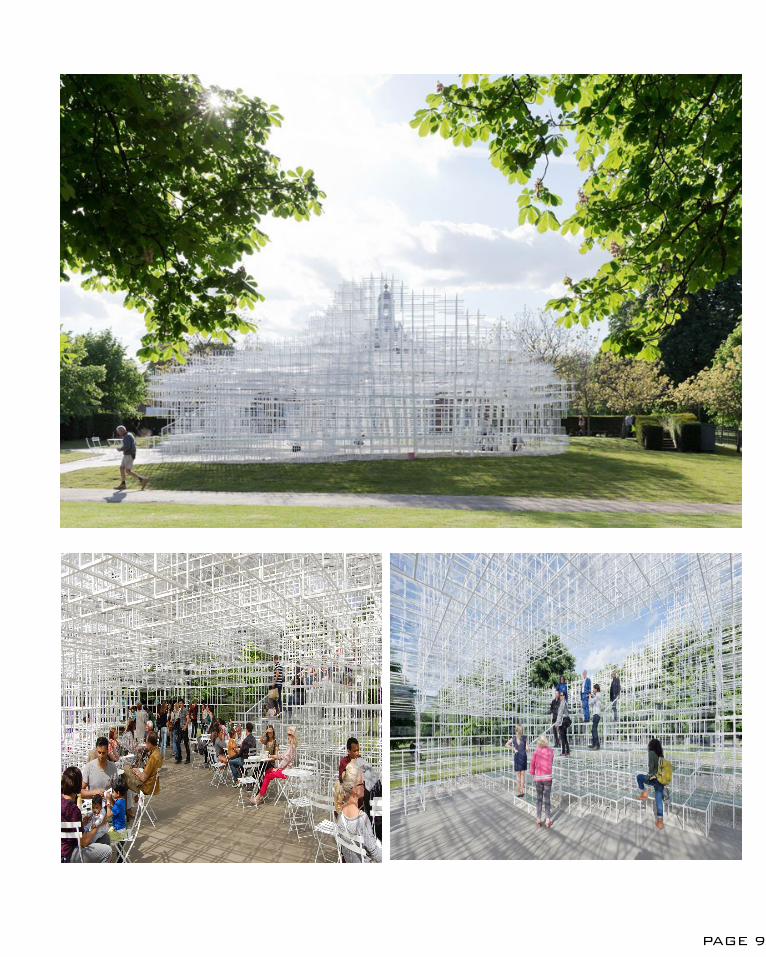
The Serpentine Pavilion, nicknamed ‘Cloud’, is designed by Japanese architect Sou Fujimoto in 2013 in a short 2 month time from design to execution in collaboration with structural engineers AECOM.1
PROJECT CONTRIBUTION
Moving away from the typical architecture definition where a building structure must consists of an enclosed space; Sou Fujimoto took the leap of creating a ‘translucent architecture’, where the pavilion itself blends into the site background and is semi-enclosed to allow people to explore the site in a new and diverse ways, i.e. via the architecture itself. The used of semi-transparent white steel tubes allow the structure to meld with the nature and even human while creating a vague view of the background to the approaching user. This instils curiosity in the user to interact with and explore further about the site and the architecture.2
The pavilion is constructed of repetitive cubic steel grid placed together at different depth which creates interesting spaces for the user to be innovative and decide on how the spaces are to be used. For instance, human sized simple cube can act as seating, viewing platform or even just as a partition of space.3 It is a fresh insight to see how the users are able to create their own experience within the architecture instead of having the architecture providing the experience that the architect wants the user to experience.
CONCLUSION
Although the Serpentine Pavilion is a temporary exhibition, it showcased a concept of architecture being part of the terrain and how an overall interesting and multi-purpose structure can be created from series of repetitive geometry.
1. AECOM, Serpentine Pavilion 2013 (London, AECOM,2013) <http://www.aecom.com/deployedfiles/Internet/Geographies/Europe/360%20Ingenuity%20Awards/serpentine_pavilion_2013.pdf> [13 March 2015] (p. 1).2. Daniel Portilla, Serpentine Pavilion/ Sou Fujimoto(Archdaily, 2013) < http://www.archdaily.com/384289/serpentine-pavilion-sou-fujimoto/> [13 March 2015].3. Daniel Portilla, Serpentine Pavilion/Sou Fujimoto.
IMAGE 2.1 (Top): The semi-transparent Serpentine Pavilion framing the backdrop of the siteIMAGE 2.2 (Bottom left): Semi-enclosed interior space allow view from inside to outside and vice-versaIMAGE 2.3 (Bottom right): Used of the different depth of cube to create multi-purpose space.Centre.
PAGE 8
PAGE 9
A2: DESIGN COMPUTATIONICD/ITKE RESEARCH PAVILION 2013-14
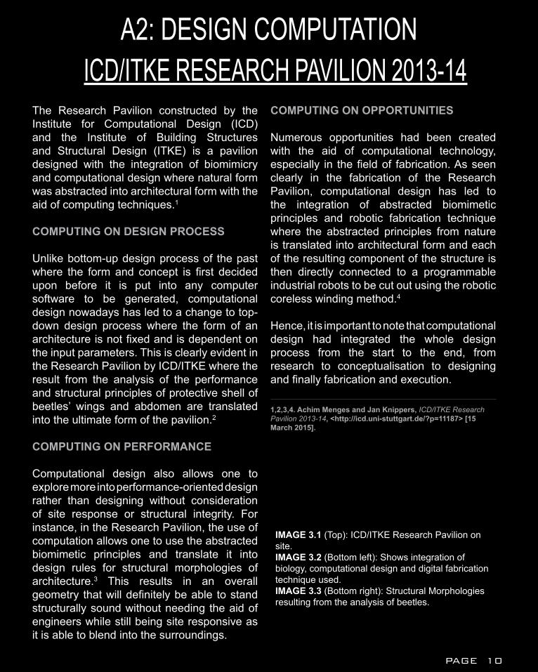
The Research Pavilion constructed by the Institute for Computational Design (ICD) and the Institute of Building Structures and Structural Design (ITKE) is a pavilion designed with the integration of biomimicry and computational design where natural form was abstracted into architectural form with the aid of computing techniques.1
COMPUTING ON DESIGN PROCESS
Unlike bottom-up design process of the past where the form and concept is first decided upon before it is put into any computer software to be generated, computational design nowadays has led to a change to top-down design process where the form of an architecture is not fixed and is dependent on the input parameters. This is clearly evident in the Research Pavilion by ICD/ITKE where the result from the analysis of the performance and structural principles of protective shell of beetles’ wings and abdomen are translated into the ultimate form of the pavilion.2
COMPUTING ON PERFORMANCE
Computational design also allows one to explore more into performance-oriented design rather than designing without consideration of site response or structural integrity. For instance, in the Research Pavilion, the use of computation allows one to use the abstracted biomimetic principles and translate it into design rules for structural morphologies of architecture.3 This results in an overall geometry that will definitely be able to stand structurally sound without needing the aid of engineers while still being site responsive as it is able to blend into the surroundings.
COMPUTING ON OPPORTUNITIES
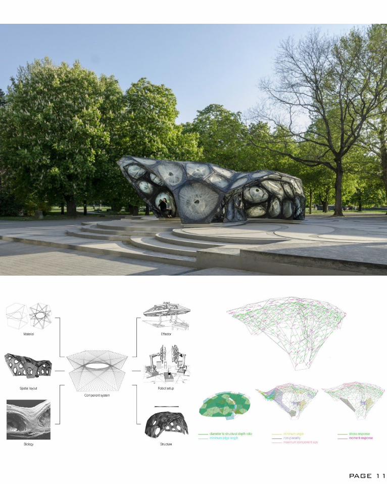
Numerous opportunities had been created with the aid of computational technology, especially in the field of fabrication. As seen clearly in the fabrication of the Research Pavilion, computational design has led to the integration of abstracted biomimetic principles and robotic fabrication technique where the abstracted principles from nature is translated into architectural form and each of the resulting component of the structure is then directly connected to a programmable industrial robots to be cut out using the robotic coreless winding method.4
Hence, it is important to note that computational design had integrated the whole design process from the start to the end, from research to conceptualisation to designing and finally fabrication and execution.
1,2,3,4. Achim Menges and Jan Knippers, ICD/ITKE Research Pavilion 2013-14, <http://icd.uni-stuttgart.de/?p=11187> [15 March 2015].
IMAGE 3.1 (Top): ICD/ITKE Research Pavilion on site.IMAGE 3.2 (Bottom left): Shows integration of biology, computational design and digital fabrication technique used.IMAGE 3.3 (Bottom right): Structural Morphologies resulting from the analysis of beetles.Centre.
PAGE 10
PAGE 11
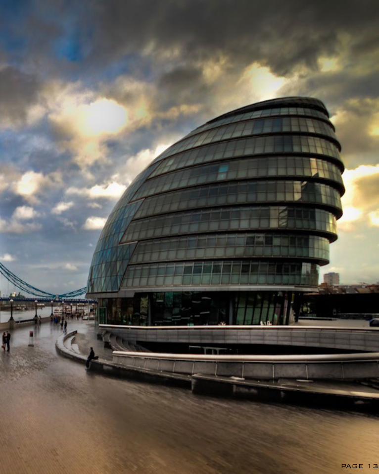
A2: DESIGN COMPUTATIONLONDON CITY HALL
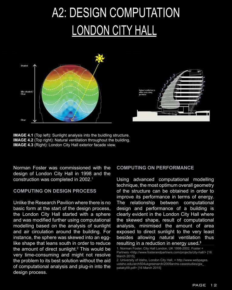
Norman Foster was commissioned with the design of London City Hall in 1998 and the construction was completed in 2002.1
COMPUTING ON DESIGN PROCESS
Unlike the Research Pavilion where there is no basic form at the start of the design process, the London City Hall started with a sphere and was modified further using computational modelling based on the analysis of sunlight and air circulation around the building. For instance, the sphere was skewed into an egg-like shape that leans south in order to reduce the amount of direct sunlight.2 This would be very time-consuming and might not resolve the problem to its best solution without the aid of computational analysis and plug-in into the design process.
COMPUTING ON PERFORMANCE
Using advanced computational modelling technique, the most optimum overall geometry of the structure can be obtained in order to improve its performance in terms of energy. The relationship between computational design and performance of a building is clearly evident in the London City Hall where the skewed shape, result of computational analysis, minimised the amount of area exposed to direct sunlight to the very least besides allowing natural ventilation thus resulting in a reduction in energy used.3
1. Norman Foster, City Hall London, UK 1998-2002, Foster + Partners <http://www.fosterandpartners.com/projects/city-hall/> [16 March 2015].2. University of Idaho, London City Hall, < http://www.webpages.uidaho.edu/arch504ukgreenarch/2009archs-casestudies/gla_pataky09.pdf> [16 March 2015]
IMAGE 4.1 (Top left): Sunlight analysis into the buidling structure. IMAGE 4.2 (Top right): Natural ventilation throughout the building.IMAGE 4.3 (Right): London City Hall exterior facade view.tre.
PAGE 12
PAGE 13
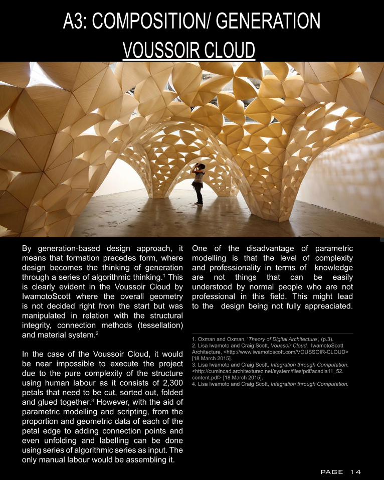
A3: COMPOSITION/ GENERATIONVOUSSOIR CLOUD
By generation-based design approach, it means that formation precedes form, where design becomes the thinking of generation through a series of algorithmic thinking.1 This is clearly evident in the Voussoir Cloud by IwamotoScott where the overall geometry is not decided right from the start but was manipulated in relation with the structural integrity, connection methods (tessellation) and material system.2
In the case of the Voussoir Cloud, it would be near impossible to execute the project due to the pure complexity of the structure using human labour as it consists of 2,300 petals that need to be cut, sorted out, folded and glued together.3 However, with the aid of parametric modelling and scripting, from the proportion and geometric data of each of the petal edge to adding connection points and even unfolding and labelling can be done using series of algorithmic series as input. The only manual labour would be assembling it.
One of the disadvantage of parametric modelling is that the level of complexity and professionality in terms of knowledge are not things that can be easily understood by normal people who are not professional in this field. This might lead to the design being not fully appreaciated.
1. Oxman and Oxman, ‘Theory of Digital Architecture’, (p.3).2. Lisa Iwamoto and Craig Scott, Voussoir Cloud, IwamotoScott Architecture, <http://www.iwamotoscott.com/VOUSSOIR-CLOUD> [18 March 2015].3. Lisa Iwamoto and Craig Scott, Integration through Computation, <http://cumincad.architexturez.net/system/files/pdf/acadia11_52.content.pdf> [18 March 2015].4. Lisa Iwamoto and Craig Scott, Integration through Computation.
PAGE 14
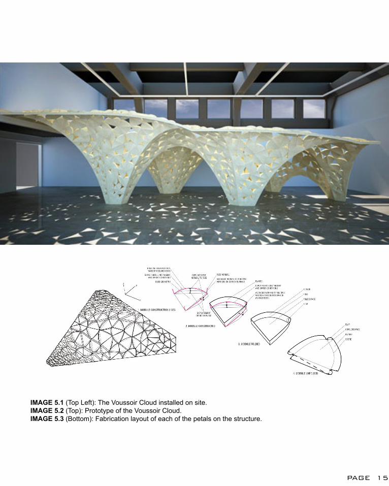
IMAGE 5.1 (Top Left): The Voussoir Cloud installed on site.IMAGE 5.2 (Top): Prototype of the Voussoir Cloud.IMAGE 5.3 (Bottom): Fabrication layout of each of the petals on the structure.
PAGE 15
METROPOL PARASOLA3: COMPOSITION/ GENERATION
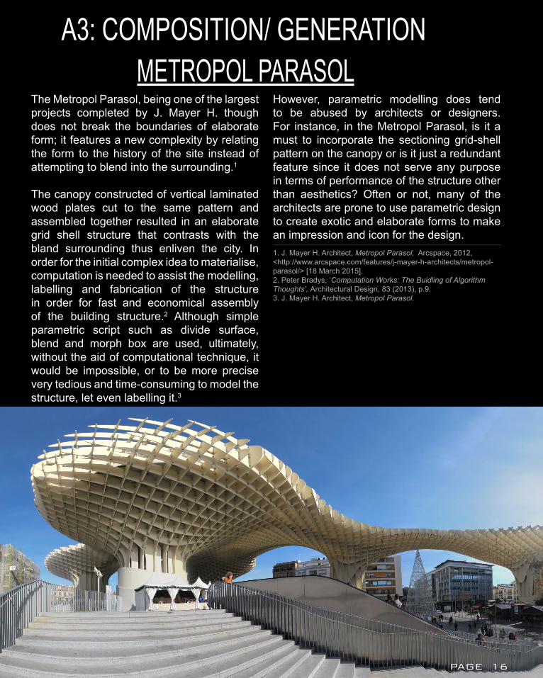
The Metropol Parasol, being one of the largest projects completed by J. Mayer H. though does not break the boundaries of elaborate form; it features a new complexity by relating the form to the history of the site instead of attempting to blend into the surrounding.1
The canopy constructed of vertical laminated wood plates cut to the same pattern and assembled together resulted in an elaborate grid shell structure that contrasts with the bland surrounding thus enliven the city. In order for the initial complex idea to materialise, computation is needed to assist the modelling, labelling and fabrication of the structure in order for fast and economical assembly of the building structure.2 Although simple parametric script such as divide surface, blend and morph box are used, ultimately, without the aid of computational technique, it would be impossible, or to be more precise very tedious and time-consuming to model the structure, let even labelling it.3
However, parametric modelling does tend to be abused by architects or designers. For instance, in the Metropol Parasol, is it a must to incorporate the sectioning grid-shell pattern on the canopy or is it just a redundant feature since it does not serve any purpose in terms of performance of the structure other than aesthetics? Often or not, many of the architects are prone to use parametric design to create exotic and elaborate forms to make an impression and icon for the design.1. J. Mayer H. Architect, Metropol Parasol, Arcspace, 2012, <http://www.arcspace.com/features/j-mayer-h-architects/metropol-parasol/> [18 March 2015].2. Peter Bradys, ‘Computation Works: The Buidling of Algorithm Thoughts’, Architectural Design, 83 (2013), p.9.3. J. Mayer H. Architect, Metropol Parasol.
PAGE 16
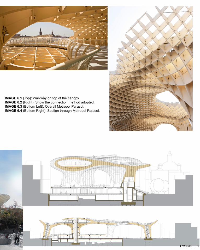
IMAGE 6.1 (Top): Walkway on top of the canopyIMAGE 6.2 (Right): Show the connection method adopted.IMAGE 6.3 (Bottom Left): Overall Metropol Parasol.IMAGE 6.4 (Bottom Right): Section through Metropol Parasol.
PAGE 17
CONCLUSIONArchitecture has progressed and advanced following the turn of the century from hand-drawn to computational drafting and now gradually progressing into parametric modelling and scripting. The aid of computational modelling has led to more complex and interesting overall geometry in buildings these days, some being extravagantly bombastic whereas the others being more logical and follows a specific system of rules.
My intended design approach is to make full use of the parametric modelling technique to create a design with a balance between exquisiteness and subtlety as the site is located in the middle of Mother Nature. It is vital that the design is able to respect the site while still achieving the overall aesthetics and functionality. Of course, most importantly, it is my utmost intention to design a space beneficial to the users at the site, be it visitors or locals, which is multi-purpose depending on how the user perceive the space similar to that of Serpentine Pavilion.
PAGE 18
LEARNING OUTCOMEPrior to commencing in Studio: Air, I have close to no knowledge in regards to the more complex aspect of architectural computing, such as algorithmic scripting and parametric modelling. For the past few weeks, after experimenting with Grasshopper, it has open up my eyes to the infinite possibilities that computational modelling can offer to us, be it the numerous interesting geometrical outcomes just by developing a mere surface using different commands or the ability to plug in site information into the parametric script so that the design is more site responsive. Being a person who is more bogged down with pens and pencils, the knowledge of the power of parametric modelling has sparked my interest to explore further in the field of computational design and to incorporate it into my future designs.
PAGE 19
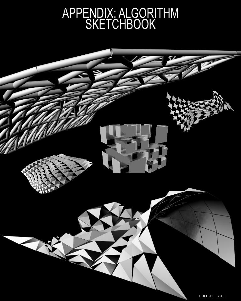
APPENDIX: ALGORITHM SKETCHBOOK
PAGE 20
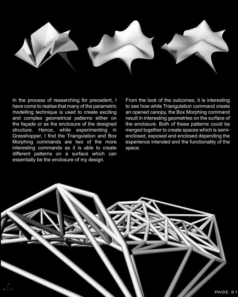
In the process of researching for precedent, I have come to realise that many of the parametric modelling technique is used to create exciting and complex geometrical patterns either on the façade or as the enclosure of the designed structure. Hence, while experimenting in Grasshopper, I find the Triangulation and Box Morphing commands are two of the more interesting commands as it is able to create different patterns on a surface which can essentially be the enclosure of my design.
From the look of the outcomes, it is interesting to see how while Triangulation command create an opened canopy, the Box Morphing command result in interesting geometries on the surface of the enclosure. Both of these patterns could be merged together to create spaces which is semi-enclosed, exposed and enclosed depending the experience intended and the functionality of the space.
PAGE 21
1. Achim Menges and Jan Knippers, ‘ICD/ITKE Research Pavilion 2013-14’, Universitat Stuttgart (2014) < http://icd.uni-stuttgart.de/?p=11187> [15 March 2015].
2. AECOM, Serpentine Pavilion 2013 (London, AECOM, 2013) <http://www.aecom.com/deployedfiles/Internet/Geographies/Europe/360%20Ingenuity%20AAward/serpentine_pavilion_2013pdf> [13 March 2015] (p.1)
3. Daniel Portilla, ‘Serpentine Pavilion/ Sou Fujimoto’, Archdaily (2013) < http://www.archdaily.com/384289/serpentine-pavilion-sou-fujimoto/> [13 March 2015].
4. J. Mayer H. Architect, ‘Metropol Parasol’, Arcspace (2012) < http://www.arcspace.com/features/j-mayer-h-architects/metropol-parasol/> [18 March 2015].
5. Lisa Iwamoto and Craig Scott, ‘Voussoir Cloud’, IwamotoScott Architecture, < http://www.iwamotoscott.com/VOUSSOIR-CLOUD> [ 18 March 2015].
6. Lisa Iwamoto and Craig Scott, Integration through Computation < http://cumincad.architexturez.net/system/files/pdf/acadia11_52.content.pdf> [18 March 2015].
7. Norman Foster, ‘City Hall London, UK 1998-2002’, Foster + Partners < http://www.fosterandpartners.com/projects/city-hall/%3E> [ 16 March 2015].
8. Peter Bradys, ‘Computation Works: The Building of Algorithm Thoughts’, Architectural Design, 83.2 (2013), p.9.
9. Rivka Oxman and Robert Oxman, Theory of Digital Architecture. (London: Routledge, 2014), (p.3).
REFERENCES
PAGE 22
1.1 https://cactuslouise.files.wordpress.com/2011/03/eden.jpg1.2 http://grimshaw-architects.com/media/cache/24/02/24023245aefc956b5049f84f1dac55fc.jpg1.3 http://grimshaw-architects.com/media/cache/62/5e/625e7ef2654e176096c4e9798ab615b2.jpg1.4 http://innovativebuildings.net/wp-content/uploads/2010/06/Water-Cube2.jpg
2.1 http://www.serpentinegalleries.org/sites/default/files/styles/half_width_custom_user_large_1x/public/images/B%20image%20serpentine_gallery_pavilion_sou_fujimoto_2013_1.jpg?itok=QSM_qYMe2.2 https://davisla.files.wordpress.com/2013/08/serpentine-gallery-pavilion-2013-sou-fujimoto-detail-entrance.jpg2.3 http://www.designboom.com/wp-content/uploads/2013/06/sou-fujimoto-serpentine-gallery-pavilion-designboom-02.jpg 3.1 http://ad009cdnb.archdaily.net.s3.amazonaws.com/wp-content/uploads/2014/06/53b21346c07a806b4b0001bb_icd-itke-research-pavilion-2015-icd-itke-university-of-stuttgart_icd-itke_rp13-14_image20-1000x707.jpg3.2 http://icd.uni-stuttgart.de/wp-content/gallery/rp2013-14-process/icd-itke_rp13-14_process09.jpg3.3 http://icd.uni-stuttgart.de/wp-content/gallery/rp2013-14-process/icd-itke_rp13-14_process10.jpg 4.1 http://www.fosterandpartners.com/media/Projects/1027/development/img13.jpg4.2 http://www.fosterandpartners.com/media/Projects/1027/development/img14.jpg4.3 http://www.fosterandpartners.com/media/1701663/img3.jpg 5.1 http://payload.cargocollective.com/1/4/140786/1871783/IwamotoScott%20VC_Figure06s_16_1040.jpg5.2 http://www.bdonline.co.uk/Journals/Graphic/k/o/t/20analysis.gif5.3 http://cumincad.architexturez.net/system/files/pdf/acadia11_52.content.pdf
6.1 http://www.arcspace.com/CropUp/-/media/756891/Metropol-Parasol-J-Maher-H-11-franck6519.jpg6.2 http://www.jmayerh.de/19-0-Metropol-Parasol.html6.3 http://upload.wikimedia.org/wikipedia/commons/6/69/Espacio_Parasol_Sevilla.jpg6.4 http://www.designboom.com/cms/images/jayme01/metropole/met17.jpg & http://api.ning.com/files/Ey2-oX-rSOvaST2OVE8uBxTO5h1ISBr4WRK5aafQ1Np35ZjQn*xGnn2XrGtPRBvkS5IpNKZwlNNoMZT2Z5PcHzKSkQ2u4wIf/SEV_Sections2.jpg
REFERENCESIMAGES
PAGE 23
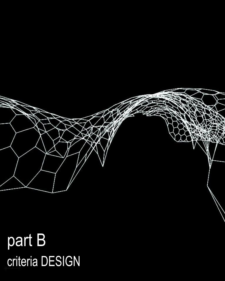
part Bcriteria DESIGN
criteria DESIGN
B1: RESEARCH FIELD : BIOMIMICRYICD/ITKE RESEARCH PAVILION 2011
OPPORTUNITIES
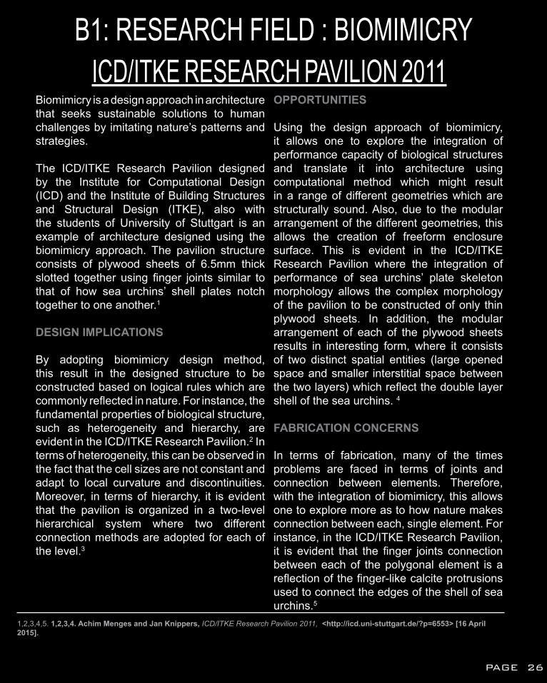
Using the design approach of biomimicry, it allows one to explore the integration of performance capacity of biological structures and translate it into architecture using computational method which might result in a range of different geometries which are structurally sound. Also, due to the modular arrangement of the different geometries, this allows the creation of freeform enclosure surface. This is evident in the ICD/ITKE Research Pavilion where the integration of performance of sea urchins’ plate skeleton morphology allows the complex morphology of the pavilion to be constructed of only thin plywood sheets. In addition, the modular arrangement of each of the plywood sheets results in interesting form, where it consists of two distinct spatial entities (large opened space and smaller interstitial space between the two layers) which reflect the double layer shell of the sea urchins. 4
FABRICATION CONCERNS
In terms of fabrication, many of the times problems are faced in terms of joints and connection between elements. Therefore, with the integration of biomimicry, this allows one to explore more as to how nature makes connection between each, single element. For instance, in the ICD/ITKE Research Pavilion, it is evident that the finger joints connection between each of the polygonal element is a reflection of the finger-like calcite protrusions used to connect the edges of the shell of sea urchins.5
Biomimicry is a design approach in architecture that seeks sustainable solutions to human challenges by imitating nature’s patterns and strategies.
The ICD/ITKE Research Pavilion designed by the Institute for Computational Design (ICD) and the Institute of Building Structures and Structural Design (ITKE), also with the students of University of Stuttgart is an example of architecture designed using the biomimicry approach. The pavilion structure consists of plywood sheets of 6.5mm thick slotted together using finger joints similar to that of how sea urchins’ shell plates notch together to one another.1
DESIGN IMPLICATIONS
By adopting biomimicry design method, this result in the designed structure to be constructed based on logical rules which are commonly reflected in nature. For instance, the fundamental properties of biological structure, such as heterogeneity and hierarchy, are evident in the ICD/ITKE Research Pavilion.2 In terms of heterogeneity, this can be observed in the fact that the cell sizes are not constant and adapt to local curvature and discontinuities. Moreover, in terms of hierarchy, it is evident that the pavilion is organized in a two-level hierarchical system where two different connection methods are adopted for each of the level.3
1,2,3,4,5. 1,2,3,4. Achim Menges and Jan Knippers, ICD/ITKE Research Pavilion 2011, <http://icd.uni-stuttgart.de/?p=6553> [16 April 2015].
PAGE 26
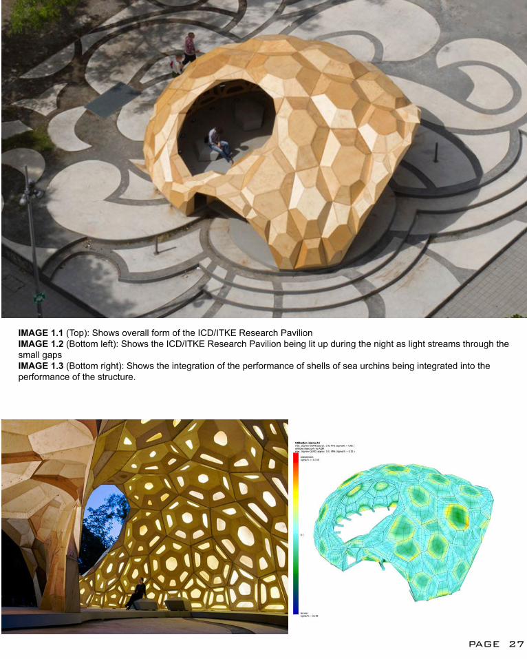
IMAGE 1.1 (Top): Shows overall form of the ICD/ITKE Research PavilionIMAGE 1.2 (Bottom left): Shows the ICD/ITKE Research Pavilion being lit up during the night as light streams through the small gapsIMAGE 1.3 (Bottom right): Shows the integration of the performance of shells of sea urchins being integrated into the performance of the structure.
PAGE 27
B2: CASE STUDY 1.0THE MORNING LINE
Collaboration between architect Aranda Lasch, artist Matthew Ritchie and Daniel Bosia of Arup’s AGU, commissioned by Thyssen-Bomemisza Art Contemporary, The Morning Line is an open cellular structure that incorporate the convergence of art, science and technology.1 By that, it means that each modular component of the structure is interchangeable and can adapt to changes in surrounding space.
The main concept behind The Morning Line is it being a modular structure, consisting of fractal building block that grows and is scaled by a fixed ratio in three dimensions to create lines, spaces and structure of the piece. This means that the fractal building block align itself along the curves which reflect the organization of modular fractal geometries following a recursive pattern or script.2
However, in order to improve the aesthetics aspect of the structure, the final structure is constructed using blackened frames which are based on patterns generated on each of the surface of the fractal geometries.3 Despite the fact that the surfaces are converted into polylines of blackened frames, it still follows the main concept that is series of geometries following the curve pattern based on a certain rules set up.
1. Thyssen-Bomemisza Art Contemporary, The Morning Line - Matthew Ritchie Aranda Lasch/ ARUP, < http://www.tba21.org/augarten_activities/49/page_2> [15 April 2015]. 2. Thyssen-Bomemisza Art Contemporary, The Morning Line - Matthew Ritchie Aranda Lasch/ ARUP.3. Thyssen-Bomemisza Art Contemporary, The Morning Line - Matthew Ritchie Aranda Lasch/ ARUP.
PAGE 28
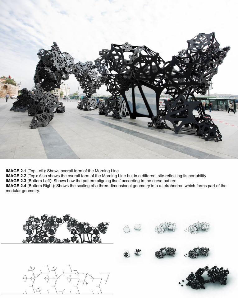
IMAGE 2.1 (Top Left): Shows overall form of the Morning LineIMAGE 2.2 (Top): Also shows the overall form of the Morning Line but in a different site reflecting its portabilityIMAGE 2.3 (Bottom Left): Shows how the pattern aligning itself according to the curve patternIMAGE 2.4 (Bottom Right): Shows the scaling of a three-dimensional geometry into a tetrahedron which forms part of the modular geometry.
B2: CASE STUDY 1.0
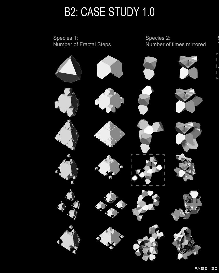
Species 1: Number of Fractal Steps
Species 2:Number of times mirrored
Species 3:Types of curve
PAGE 30
Species 2:Number of times mirrored
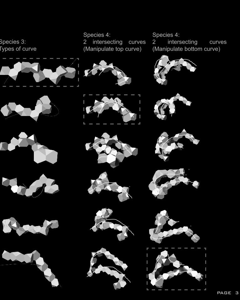
Species 3:Types of curve
Species 4:2 intersecting curves (Manipulate top curve)
Species 4:2 intersecting curves (Manipulate bottom curve)
PAGE 31
B2: CASE STUDY 1.0ANALYSIS
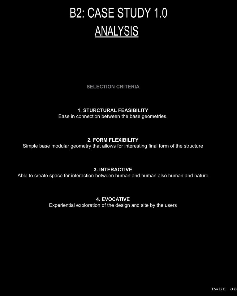
SELECTION CRITERIA
1. STURCTURAL FEASIBILITYEase in connection between the base geometries.
2. FORM FLEXIBILITYSimple base modular geometry that allows for interesting final form of the structure
3. INTERACTIVEAble to create space for interaction between human and human also human and nature
4. EVOCATIVEExperiential exploration of the design and site by the users
PAGE 32
SPECIES 1
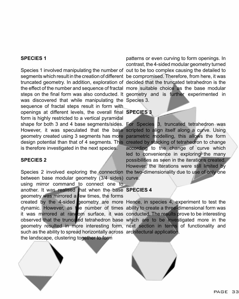
Species 1 involved manipulating the number of segments which result in the creation of different truncated geometry. In addition, exploration of the effect of the number and sequence of fractal steps on the final form was also conducted. It was discovered that while manipulating the sequence of fractal steps result in form with openings at different levels, the overall final form is highly restricted to a vertical pyramidal shape for both 3 and 4 base segments/sides. However, it was speculated that the base geometry created using 3 segments has more design potential than that of 4 segments. This is therefore investigated in the next species.
SPECIES 2
Species 2 involved exploring the connection between base modular geometry (3/4 sides) using mirror command to connect one to another. It was realised that when the base geometry was mirrored a few times, the forms created by the 4-sided geometry are more dynamic. However, as the number of times it was mirrored at random surface, it was observed that the truncated tetrahedron base geometry resulted in more interesting form, such as the ability to spread horizontally across the landscape, clustering together to form
patterns or even curving to form openings. In contrast, the 4-sided modular geometry turned out to be too complex causing the detailed to be compromised. Therefore, from here, it was decided that the truncated tetrahedron is the more suitable choice as the base modular geometry and is further experimented in Species 3.
SPECIES 3
For Species 3, truncated tetrahedron was scripted to align itself along a curve. Using parametric modelling, this allows the form created by stacking of tetrahedron to change according to the change of curve which led to convenience in exploring the many possibilities as seen in the iterations created. However, the iterations were still limited by the two-dimensionality due to use of only one curve.
SPECIES 4
Hence, in species 4, experiment to test the ability to create a three-dimensional form was conducted. The results prove to be interesting which are to be investigated more in the next section in terms of functionality and architectural application.
PAGE 33
B2: CASE STUDY 1.0DESIGN SPECULATION
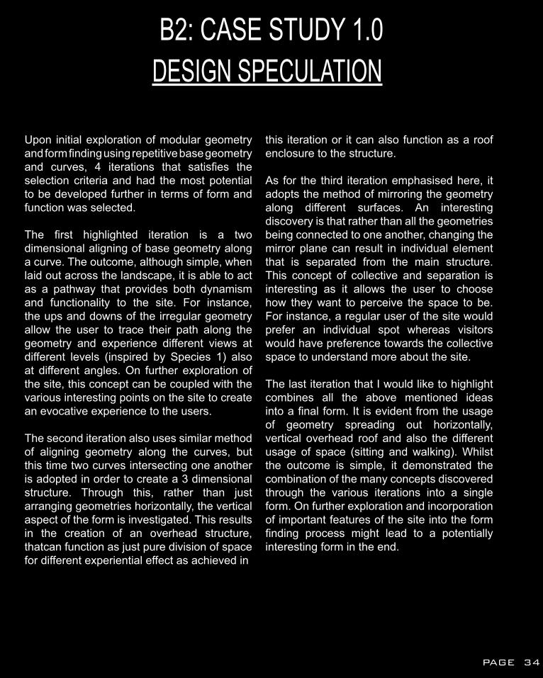
Upon initial exploration of modular geometry and form finding using repetitive base geometry and curves, 4 iterations that satisfies the selection criteria and had the most potential to be developed further in terms of form and function was selected.
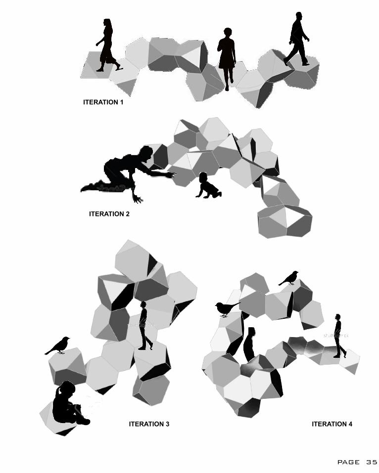
The first highlighted iteration is a two dimensional aligning of base geometry along a curve. The outcome, although simple, when laid out across the landscape, it is able to act as a pathway that provides both dynamism and functionality to the site. For instance, the ups and downs of the irregular geometry allow the user to trace their path along the geometry and experience different views at different levels (inspired by Species 1) also at different angles. On further exploration of the site, this concept can be coupled with the various interesting points on the site to create an evocative experience to the users.
The second iteration also uses similar method of aligning geometry along the curves, but this time two curves intersecting one another is adopted in order to create a 3 dimensional structure. Through this, rather than just arranging geometries horizontally, the vertical aspect of the form is investigated. This results in the creation of an overhead structure, thatcan function as just pure division of space for different experiential effect as achieved in
this iteration or it can also function as a roof enclosure to the structure.
As for the third iteration emphasised here, it adopts the method of mirroring the geometry along different surfaces. An interesting discovery is that rather than all the geometries being connected to one another, changing the mirror plane can result in individual element that is separated from the main structure. This concept of collective and separation is interesting as it allows the user to choose how they want to perceive the space to be. For instance, a regular user of the site would prefer an individual spot whereas visitors would have preference towards the collective space to understand more about the site.
The last iteration that I would like to highlight combines all the above mentioned ideas into a final form. It is evident from the usage of geometry spreading out horizontally, vertical overhead roof and also the different usage of space (sitting and walking). Whilst the outcome is simple, it demonstrated the combination of the many concepts discovered through the various iterations into a single form. On further exploration and incorporation of important features of the site into the form finding process might lead to a potentially interesting form in the end.
PAGE 34
ITERATION 1
ITERATION 2
ITERATION 3 ITERATION 4
PAGE 35
B3: CASE STUDY 2.0REVERSE ENGINEERING
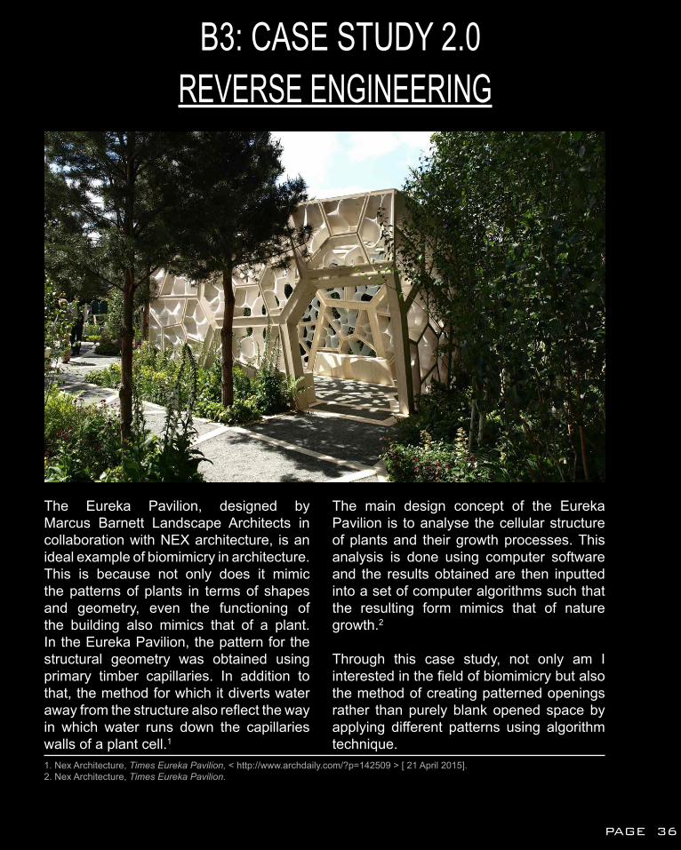
The Eureka Pavilion, designed by Marcus Barnett Landscape Architects in collaboration with NEX architecture, is an ideal example of biomimicry in architecture. This is because not only does it mimic the patterns of plants in terms of shapes and geometry, even the functioning of the building also mimics that of a plant. In the Eureka Pavilion, the pattern for the structural geometry was obtained using primary timber capillaries. In addition to that, the method for which it diverts water away from the structure also reflect the way in which water runs down the capillaries walls of a plant cell.1
The main design concept of the Eureka Pavilion is to analyse the cellular structure of plants and their growth processes. This analysis is done using computer software and the results obtained are then inputted into a set of computer algorithms such that the resulting form mimics that of nature growth.2
Through this case study, not only am I interested in the field of biomimicry but also the method of creating patterned openings rather than purely blank opened space by applying different patterns using algorithm technique.
1. Nex Architecture, Times Eureka Pavilion, < http://www.archdaily.com/?p=142509 > [ 21 April 2015].2. Nex Architecture, Times Eureka Pavilion.
PAGE 36
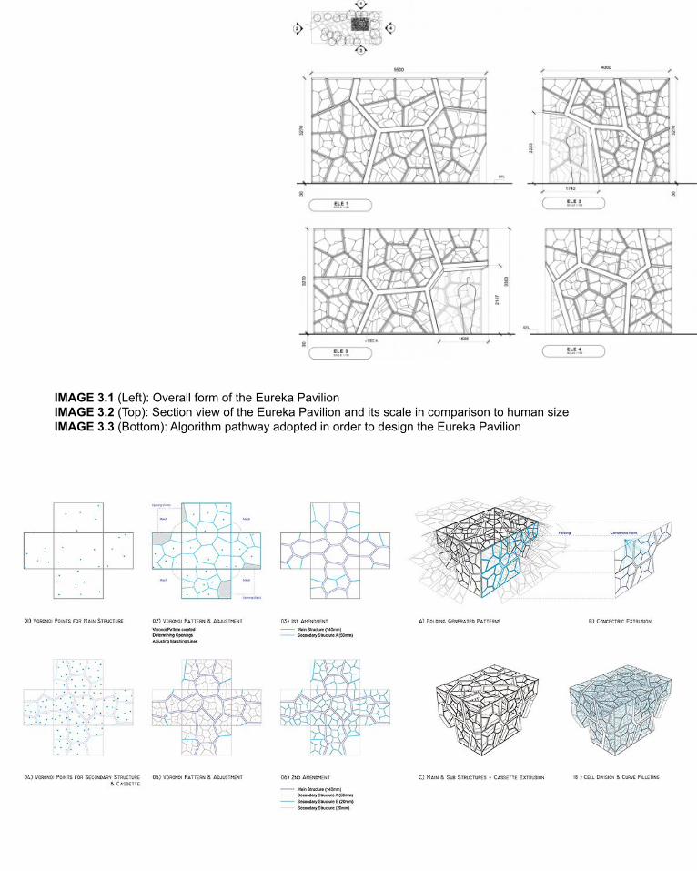
IMAGE 3.1 (Left): Overall form of the Eureka PavilionIMAGE 3.2 (Top): Section view of the Eureka Pavilion and its scale in comparison to human sizeIMAGE 3.3 (Bottom): Algorithm pathway adopted in order to design the Eureka Pavilion
B3: CASE STUDY 2.0REVERSE ENGINEERING
1 2 3
5 6
CURVE POPULATE 2D VORONOI 2D REGION INTERSECTION
CURVE- 0.25
21
7
PAGE 38
- 0.25
4
7
6
5
4
3
2
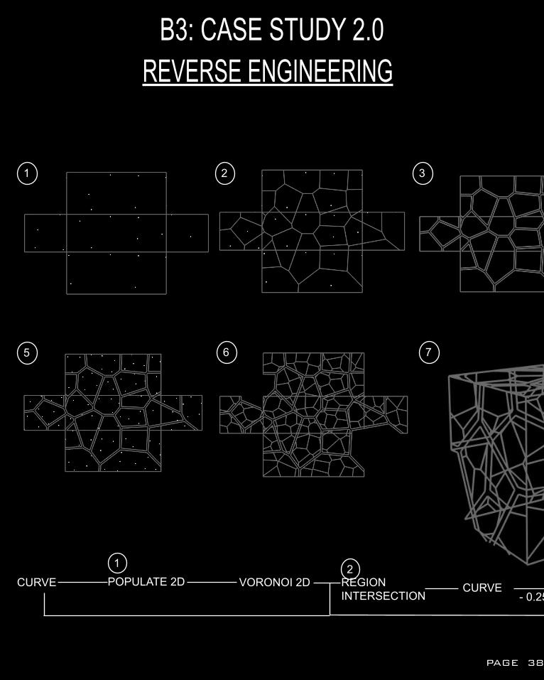
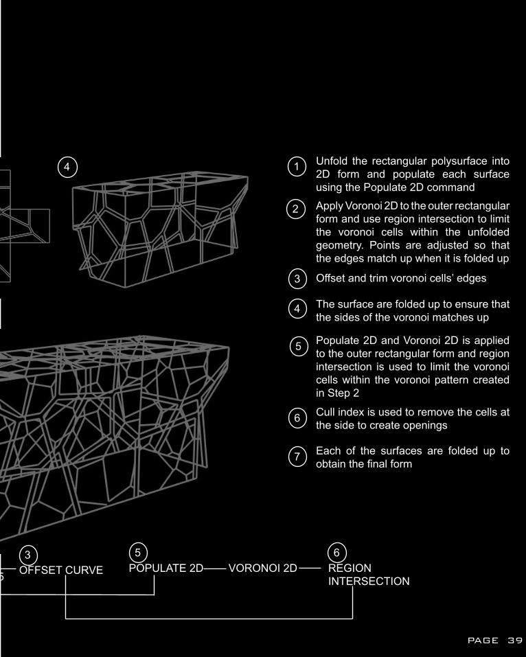
1 Unfold the rectangular polysurface into 2D form and populate each surface using the Populate 2D commandApply Voronoi 2D to the outer rectangular form and use region intersection to limit the voronoi cells within the unfolded geometry. Points are adjusted so that the edges match up when it is folded up
Offset and trim voronoi cells’ edges
The surface are folded up to ensure that the sides of the voronoi matches up
Populate 2D and Voronoi 2D is applied to the outer rectangular form and region intersection is used to limit the voronoi cells within the voronoi pattern created in Step 2
Cull index is used to remove the cells at the side to create openings
Each of the surfaces are folded up to obtain the final form
POPULATE 2D VORONOI 2D REGION INTERSECTION
OFFSET CURVE653
PAGE 39
REVERSE ENGINEERINGB3: CASE STUDY 2.0
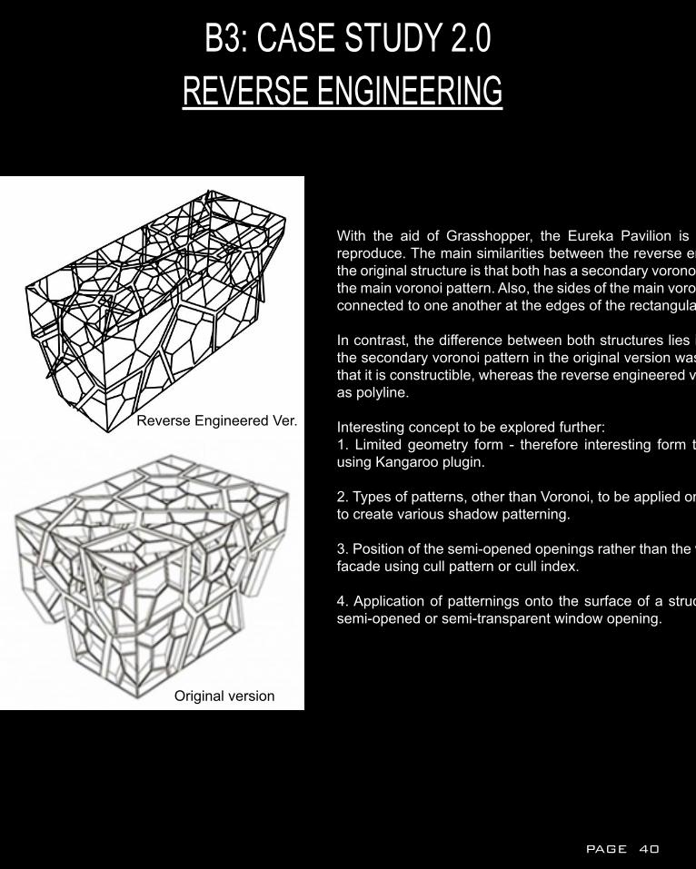
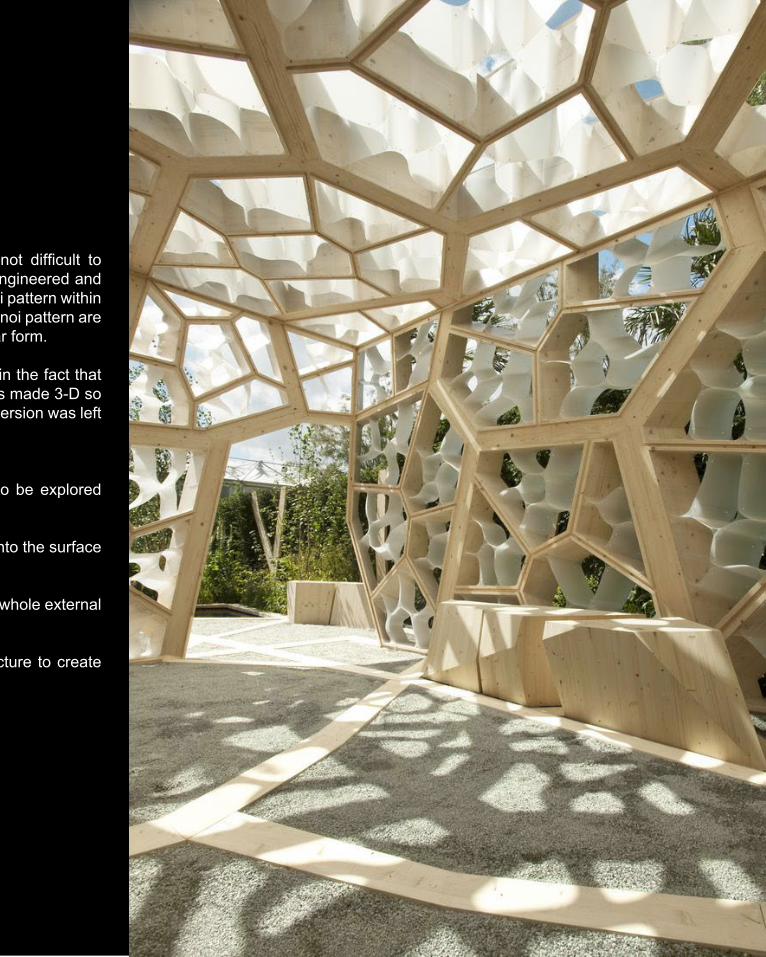
With the aid of Grasshopper, the Eureka Pavilion is not difficult to reproduce. The main similarities between the reverse engineered and the original structure is that both has a secondary voronoi pattern within the main voronoi pattern. Also, the sides of the main voronoi pattern are connected to one another at the edges of the rectangular form.
In contrast, the difference between both structures lies in the fact that the secondary voronoi pattern in the original version was made 3-D so that it is constructible, whereas the reverse engineered version was left as polyline.
Interesting concept to be explored further:1. Limited geometry form - therefore interesting form to be explored using Kangaroo plugin.
2. Types of patterns, other than Voronoi, to be applied onto the surface to create various shadow patterning.
3. Position of the semi-opened openings rather than the whole external facade using cull pattern or cull index.
4. Application of patternings onto the surface of a structure to create semi-opened or semi-transparent window opening.
Reverse Engineered Ver.
Original version
PAGE 40
With the aid of Grasshopper, the Eureka Pavilion is not difficult to reproduce. The main similarities between the reverse engineered and the original structure is that both has a secondary voronoi pattern within the main voronoi pattern. Also, the sides of the main voronoi pattern are connected to one another at the edges of the rectangular form.
In contrast, the difference between both structures lies in the fact that the secondary voronoi pattern in the original version was made 3-D so that it is constructible, whereas the reverse engineered version was left as polyline.
Interesting concept to be explored further:1. Limited geometry form - therefore interesting form to be explored using Kangaroo plugin.
2. Types of patterns, other than Voronoi, to be applied onto the surface to create various shadow patterning.
3. Position of the semi-opened openings rather than the whole external facade using cull pattern or cull index.
4. Application of patternings onto the surface of a structure to create semi-opened or semi-transparent window opening.
B4: TECHNIQUE DEVELOPMENTITERATIONS
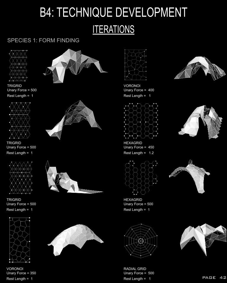
TRIGRIDUnary Force = 500 Rest Length = 1
TRIGRIDUnary Force = 500Rest Length = 1
TRIGRIDUnary Force = 500Rest Length = 1
VORONOIUnary Force = 350Rest Length = 1
VORONOIUnary Force = 400Rest Length = 1
HEXAGRIDUnary Force = 450Rest Length = 1.2
HEXAGRIDUnary Force = 500 Rest Length = 1
RADIAL GRIDUnary Force = 500Rest Length = 1
SPECIES 1: FORM FINDING
PAGE 42
ITERATIONSB4: TECHNIQUE DEVELOPMENT
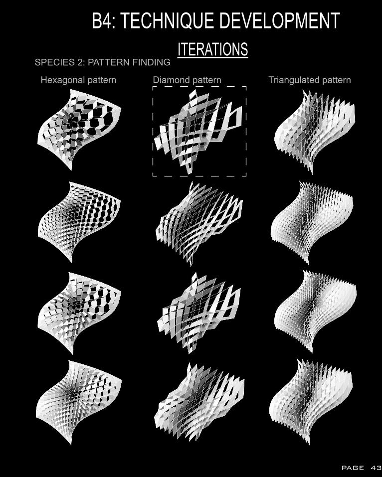
SPECIES 2: PATTERN FINDING
Hexagonal pattern Diamond pattern Triangulated pattern
PAGE 43
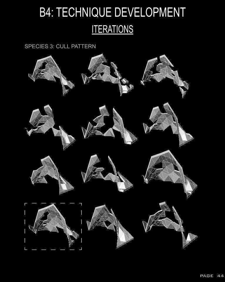
SPECIES 3: CULL PATTERN
B4: TECHNIQUE DEVELOPMENTITERATIONS
PAGE 44
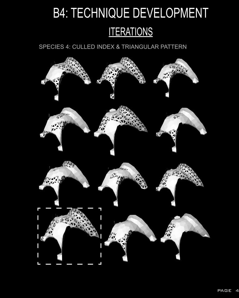
B4: TECHNIQUE DEVELOPMENTITERATIONS
SPECIES 4: CULLED INDEX & TRIANGULAR PATTERN
PAGE 45
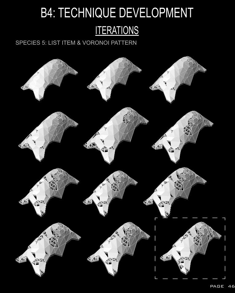
B4: TECHNIQUE DEVELOPMENTITERATIONS
SPECIES 5: LIST ITEM & VORONOI PATTERN
PAGE 46
B4: TECHNIQUE DEVELOPMENTANALYSIS
SELECTION CRITERIA REVISIT
1. CONSTRUCTION FEASIBILITYEase in connection between the components
2. INTERACTIVEAble to create space for interaction between human and human also human and nature
3. EVOCATIVEExperiential exploration of the design and site by the users
PAGE 47
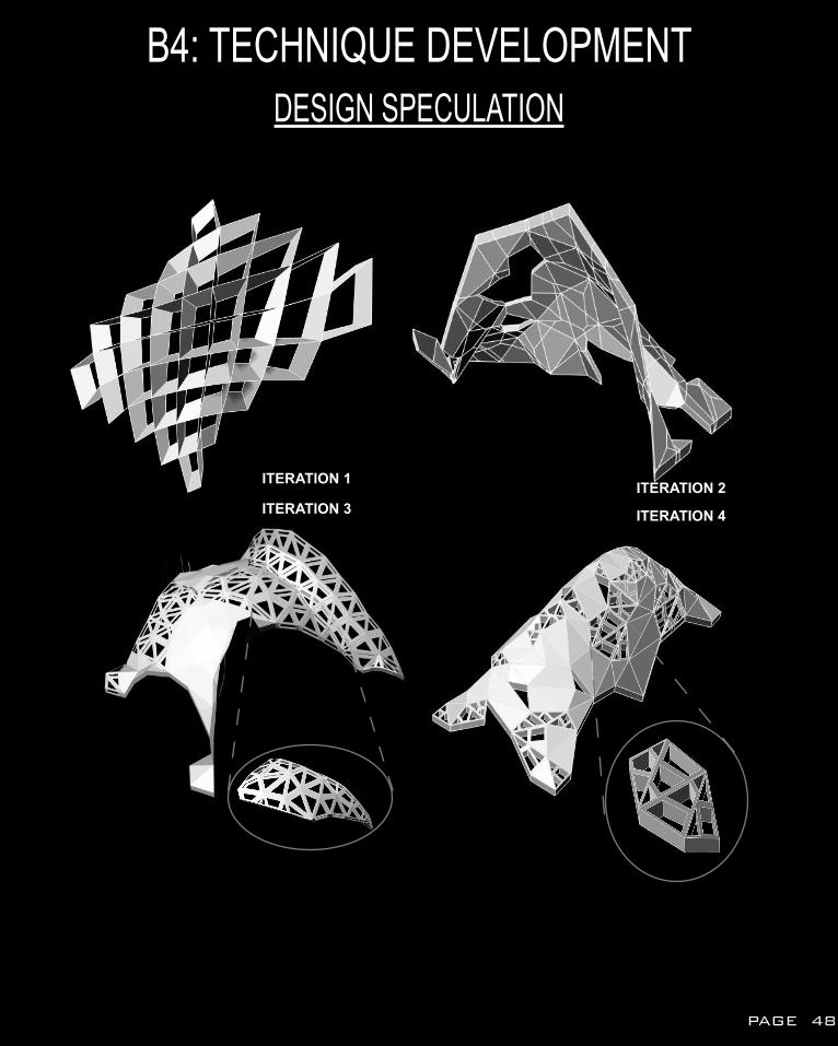
B4: TECHNIQUE DEVELOPMENTDESIGN SPECULATION
ITERATION 1 ITERATION 2ITERATION 3 ITERATION 4
PAGE 48
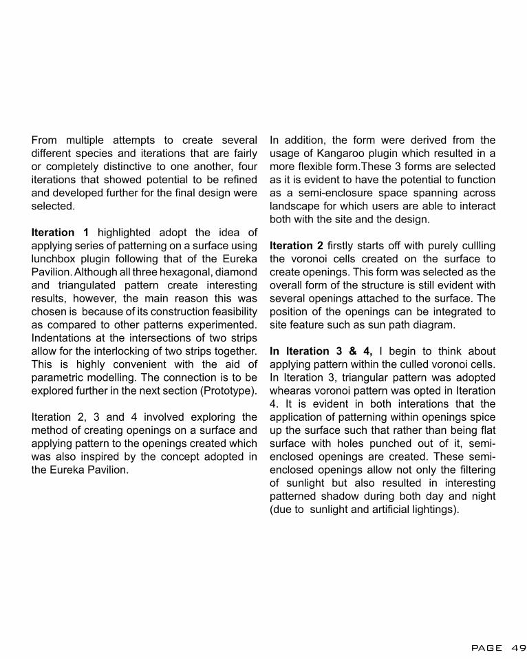
From multiple attempts to create several different species and iterations that are fairly or completely distinctive to one another, four iterations that showed potential to be refined and developed further for the final design were selected.
Iteration 1 highlighted adopt the idea of applying series of patterning on a surface using lunchbox plugin following that of the Eureka Pavilion. Although all three hexagonal, diamond and triangulated pattern create interesting results, however, the main reason this was chosen is because of its construction feasibility as compared to other patterns experimented. Indentations at the intersections of two strips allow for the interlocking of two strips together.This is highly convenient with the aid of parametric modelling. The connection is to be explored further in the next section (Prototype).
Iteration 2, 3 and 4 involved exploring the method of creating openings on a surface and applying pattern to the openings created which was also inspired by the concept adopted in the Eureka Pavilion.
In addition, the form were derived from the usage of Kangaroo plugin which resulted in a more flexible form.These 3 forms are selected as it is evident to have the potential to function as a semi-enclosure space spanning across landscape for which users are able to interact both with the site and the design.
Iteration 2 firstly starts off with purely cullling the voronoi cells created on the surface to create openings. This form was selected as the overall form of the structure is still evident with several openings attached to the surface. The position of the openings can be integrated to site feature such as sun path diagram.
In Iteration 3 & 4, I begin to think about applying pattern within the culled voronoi cells. In Iteration 3, triangular pattern was adopted whearas voronoi pattern was opted in Iteration 4. It is evident in both interations that the application of patterning within openings spice up the surface such that rather than being flat surface with holes punched out of it, semi-enclosed openings are created. These semi-enclosed openings allow not only the filtering of sunlight but also resulted in interesting patterned shadow during both day and night (due to sunlight and artificial lightings).
PAGE 49
B5: TECHNIQUE: PROTOTYPE
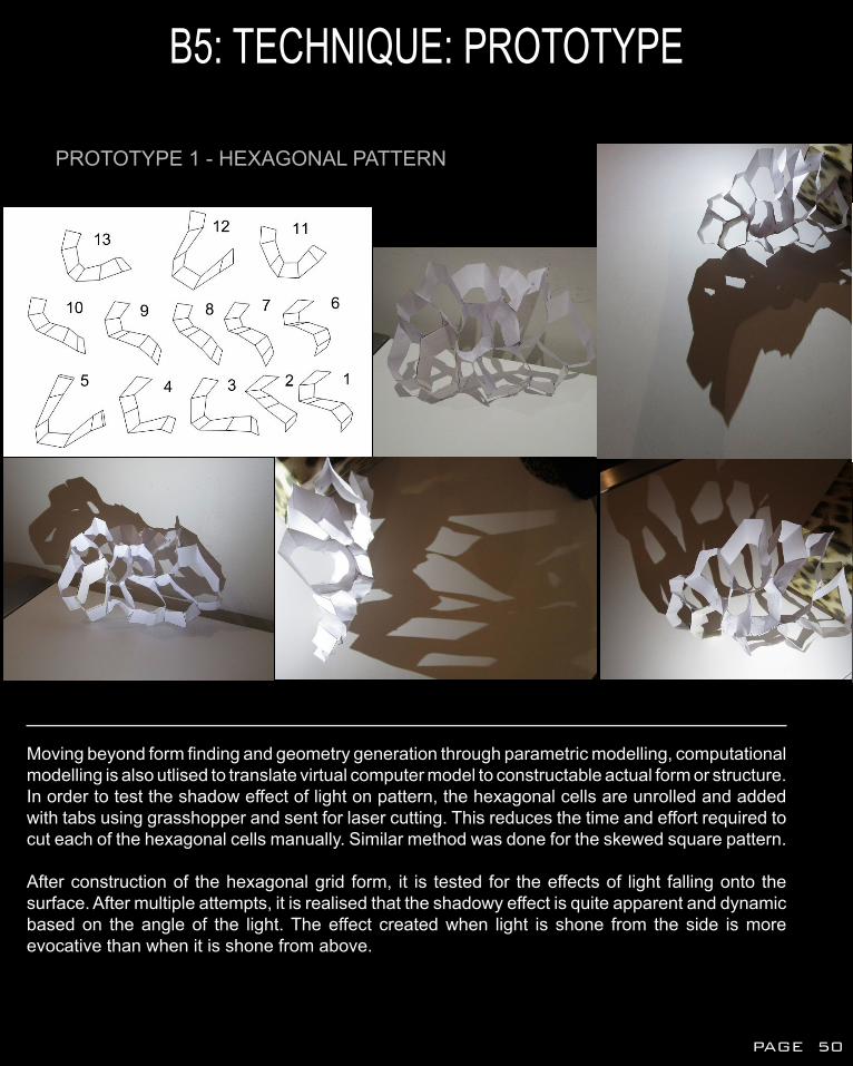
PROTOTYPE 1 - HEXAGONAL PATTERN
Moving beyond form finding and geometry generation through parametric modelling, computational modelling is also utlised to translate virtual computer model to constructable actual form or structure. In order to test the shadow effect of light on pattern, the hexagonal cells are unrolled and added with tabs using grasshopper and sent for laser cutting. This reduces the time and effort required to cut each of the hexagonal cells manually. Similar method was done for the skewed square pattern.
After construction of the hexagonal grid form, it is tested for the effects of light falling onto the surface. After multiple attempts, it is realised that the shadowy effect is quite apparent and dynamic based on the angle of the light. The effect created when light is shone from the side is more evocative than when it is shone from above.
PAGE 50
B5: TECHNIQUE: PROTOTYPE
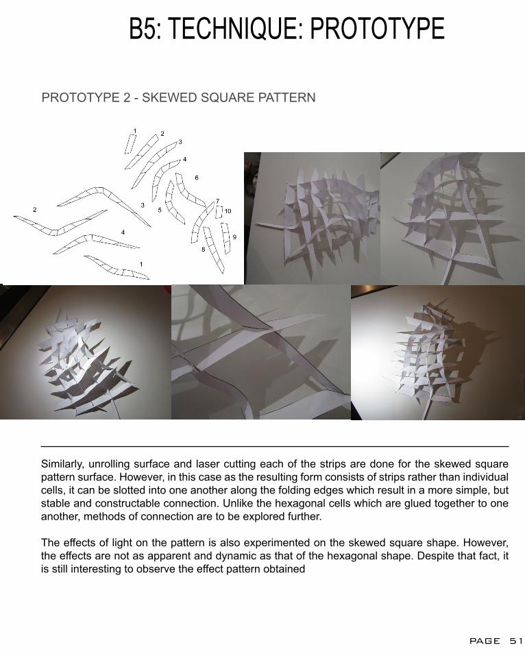
PROTOTYPE 2 - SKEWED SQUARE PATTERN
Similarly, unrolling surface and laser cutting each of the strips are done for the skewed square pattern surface. However, in this case as the resulting form consists of strips rather than individual cells, it can be slotted into one another along the folding edges which result in a more simple, but stable and constructable connection. Unlike the hexagonal cells which are glued together to one another, methods of connection are to be explored further.
The effects of light on the pattern is also experimented on the skewed square shape. However, the effects are not as apparent and dynamic as that of the hexagonal shape. Despite that fact, it is still interesting to observe the effect pattern obtained
PAGE 51
B6: DESIGN PROPOSALSITE ANALYSIS
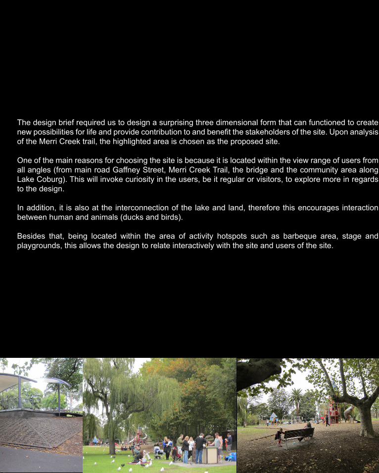
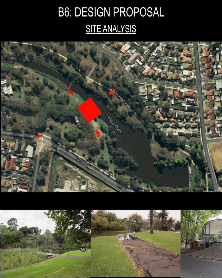
The design brief required us to design a surprising three dimensional form that can functioned to create new possibilities for life and provide contribution to and benefit the stakeholders of the site. Upon analysis of the Merri Creek trail, the highlighted area is chosen as the proposed site.
One of the main reasons for choosing the site is because it is located within the view range of users from all angles (from main road Gaffney Street, Merri Creek Trail, the bridge and the community area along Lake Coburg). This will invoke curiosity in the users, be it regular or visitors, to explore more in regards to the design.
In addition, it is also at the interconnection of the lake and land, therefore this encourages interaction between human and animals (ducks and birds).
Besides that, being located within the area of activity hotspots such as barbeque area, stage and playgrounds, this allows the design to relate interactively with the site and users of the site.
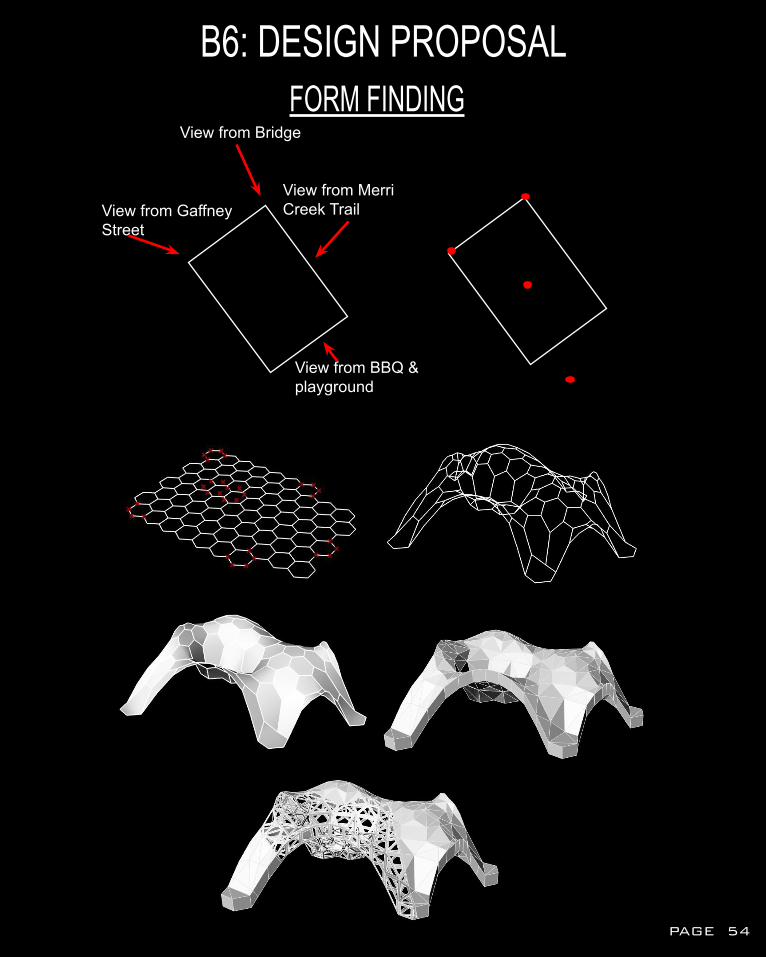
B6: DESIGN PROPOSALFORM FINDING
View from Gaffney Street
View from Bridge
View from Merri Creek Trail
View from BBQ & playground
PAGE 54
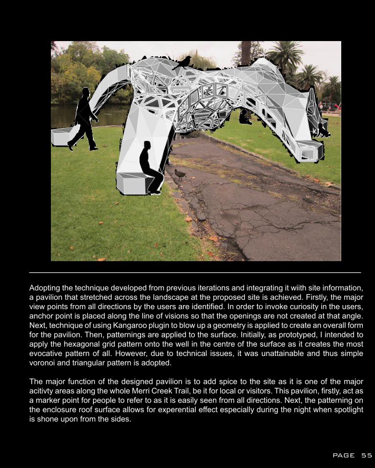
Adopting the technique developed from previous iterations and integrating it wiith site information, a pavilion that stretched across the landscape at the proposed site is achieved. Firstly, the major view points from all directions by the users are identified. In order to invoke curiosity in the users, anchor point is placed along the line of visions so that the openings are not created at that angle. Next, technique of using Kangaroo plugin to blow up a geometry is applied to create an overall form for the pavilion. Then, patternings are applied to the surface. Initially, as prototyped, I intended to apply the hexagonal grid pattern onto the well in the centre of the surface as it creates the most evocative pattern of all. However, due to technical issues, it was unattainable and thus simple voronoi and triangular pattern is adopted.
The major function of the designed pavilion is to add spice to the site as it is one of the major acitivty areas along the whole Merri Creek Trail, be it for local or visitors. This pavilion, firstly, act as a marker point for people to refer to as it is easily seen from all directions. Next, the patterning on the enclosure roof surface allows for experential effect especially during the night when spotlight is shone upon from the sides.
PAGE 55
B7: LEARNING OBJECTIVES & OUTCOME
Through this design process, my ability to make a case for proposals has improved through the consistent feedback of my work each week from the tutor and reflecting on it thereafter. Through this, I had realized that for every step that we take in terms of design process, it is important to evaluate the limitations and possibilities that it can provide us with and not just blindly following instructions without having a deep critical analysis of the knowledge obtained.
In terms of computational techniques, after multiple attempts at reverse engineering and experimenting with different scripts from the forum in order to push the iterations to its boundaries, I finally had the slightest bit of knowledge in terms of computational and parametric modelling. Also, through the numerous case-study projects that led to multiple failures and manual trimming due to insufficient knowledge in terms of grasshopper, although frustrating at times, had led to a clearer understanding of the fundamental logic underlying algorithm patterns and also the limitless boundaries that computational modelling offers to designers.
Through research and looking for design projects that relate to my research field, only did I realized that there are many projects out there that might look complex from the exterior view of it but in actual fact can be obtained using Grasshopper and various plugins. It is apparent that computation has gradually become the dominant method of designing especially among the younger generation.
As a whole, looking at precedents and tweaking with parametric modelling script provided had widen my horizon in the field of computational modelling and a better understanding as to how each component function and are connected to one another. Although manually writing up a whole script for a design structure might still be a bit of an extreme request on my side, however, I had had the basic understanding of parametric modelling and how it can be applied into design process through the reverse engineering exercise and matrix table.
PAGE 56
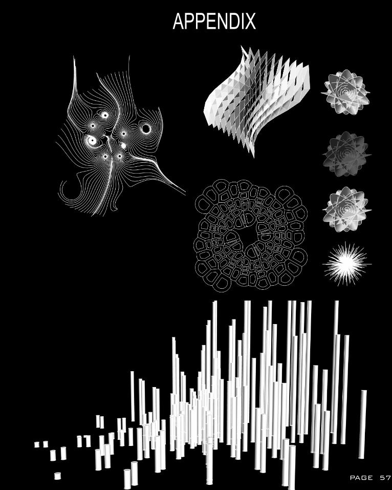
APPENDIX
PAGE 57
REFERENCES
1.1 http://static1.squarespace.com/static/51eed906e4b0953024980af9/52756b1fe4b0144957d2f690/52756b20e4b08c252c72a381/1383426850066/1.jpg1.2 http://icd.uni-stuttgart.de/icd-imagedb/Web_ICD_ResearchPavilion_2011.jpg1.3 http://www.detail-online.com/uploads/pics/431_800_709_01.jpg
2.1 http://www.tb-cms.org/data/exhibition/103/3384.jpg2.2 http://images.andrearosengallery.com/www_andrearosengallery_com/03___Photo_by_Uli_Deck0.jpg2.3 https://farm4.staticflickr.com/3098/3191703998_315e2450e9_b.jpg2.4 http://www.cambridgeliteraryreview.org/wp-content/uploads/3376593247_e0674d728e_b2.jpg
3.1 http://ad009cdnb.archdaily.net/wp-content/uploads/2011/06/1307636154-image-final-d.jpg3.2 http://ad009cdnb.archdaily.net/wp-content/uploads/2011/06/1307636090-plans-final-b-528x470.jpg3.3 http://www.e-architect.co.uk/images/jpgs/london/eureka_pavilion_n150611_11.jpg
IMAGES
1. Achim Menges and Jan Knippers, ‘ICD/ITKE Research Pavilion 2011’, Universitat Stuttgart (2011) < http://icd.uni-stuttgart.de/?p=6553> [16 April 2015].
2. Nex Architecture, ‘Times Eureka Pavilion’, < http://www.archdaily.com/142509/times-eureka-pavilion-nex-architecture/> [21 April 2015].
3. Thyssen- Bomemisza Art Contemporary, ‘The Morning Line- Matthew Ritchie Aranda Lasch/ ARUP’, < http://www.tba21.org/augarten_activities/49/page_2> [16 April 2015].
PAGE 58
detailed DESIGN
part Cdetailed DESIGN
C1: DESIGN CONCEPTFEEDBACK REFLECTION
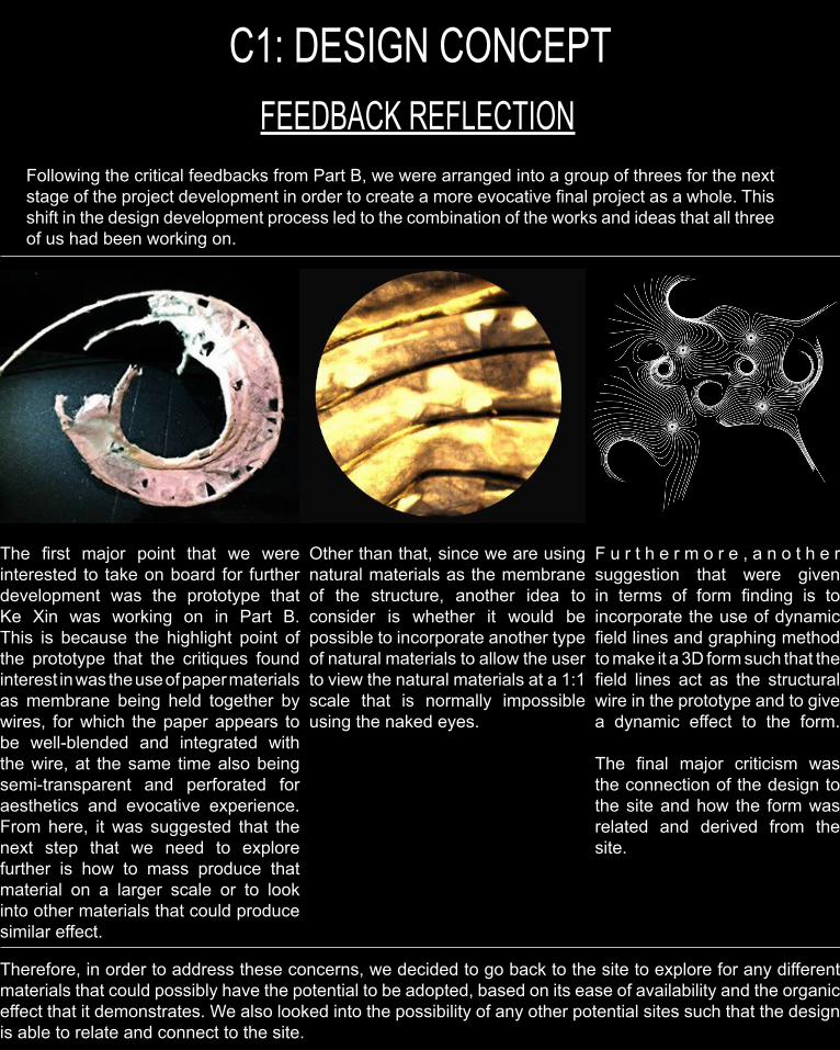
Following the critical feedbacks from Part B, we were arranged into a group of threes for the next stage of the project development in order to create a more evocative final project as a whole. This shift in the design development process led to the combination of the works and ideas that all three of us had been working on.
The first major point that we were interested to take on board for further development was the prototype that Ke Xin was working on in Part B. This is because the highlight point of the prototype that the critiques found interest in was the use of paper materials as membrane being held together by wires, for which the paper appears to be well-blended and integrated with the wire, at the same time also being semi-transparent and perforated for aesthetics and evocative experience. From here, it was suggested that the next step that we need to explore further is how to mass produce that material on a larger scale or to look into other materials that could produce similar effect.
Other than that, since we are using natural materials as the membrane of the structure, another idea to consider is whether it would be possible to incorporate another type of natural materials to allow the user to view the natural materials at a 1:1 scale that is normally impossible using the naked eyes.
F u r t h e r m o r e , a n o t h e r suggestion that were given in terms of form finding is to incorporate the use of dynamic field lines and graphing method to make it a 3D form such that the field lines act as the structural wire in the prototype and to give a dynamic effect to the form.
The final major criticism was the connection of the design to the site and how the form was related and derived from the site.
Therefore, in order to address these concerns, we decided to go back to the site to explore for any different materials that could possibly have the potential to be adopted, based on its ease of availability and the organic effect that it demonstrates. We also looked into the possibility of any other potential sites such that the design is able to relate and connect to the site.
C1: DESIGN CONCEPTFINAL DESIGN CONCEPT
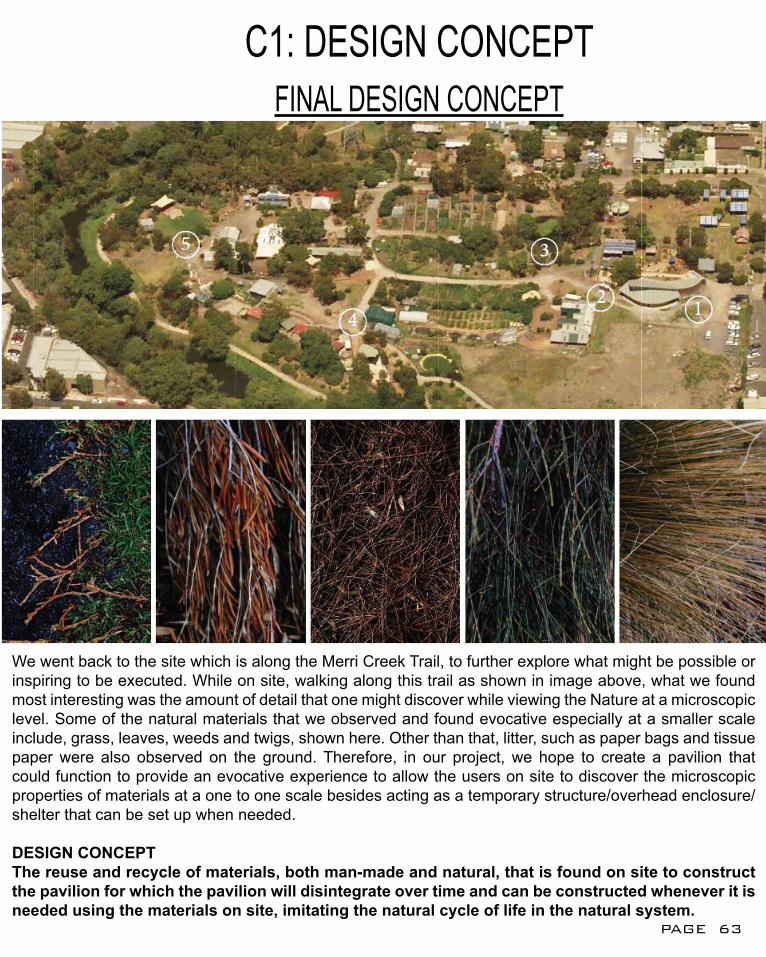
We went back to the site which is along the Merri Creek Trail, to further explore what might be possible or inspiring to be executed. While on site, walking along this trail as shown in image above, what we found most interesting was the amount of detail that one might discover while viewing the Nature at a microscopic level. Some of the natural materials that we observed and found evocative especially at a smaller scale include, grass, leaves, weeds and twigs, shown here. Other than that, litter, such as paper bags and tissue paper were also observed on the ground. Therefore, in our project, we hope to create a pavilion that could function to provide an evocative experience to allow the users on site to discover the microscopic properties of materials at a one to one scale besides acting as a temporary structure/overhead enclosure/shelter that can be set up when needed.
DESIGN CONCEPTThe reuse and recycle of materials, both man-made and natural, that is found on site to construct the pavilion for which the pavilion will disintegrate over time and can be constructed whenever it is needed using the materials on site, imitating the natural cycle of life in the natural system.
PAGE 63
C1: DESIGN CONCEPTSITE ANALYSIS REVISIT
FLOW/CIRCULATION
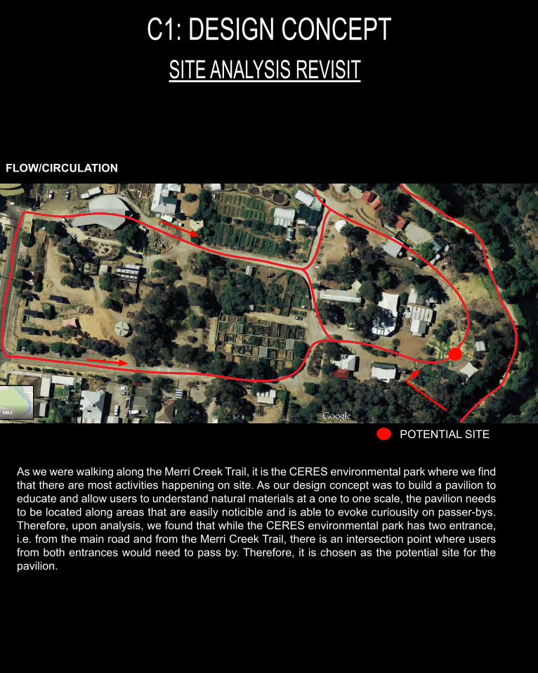
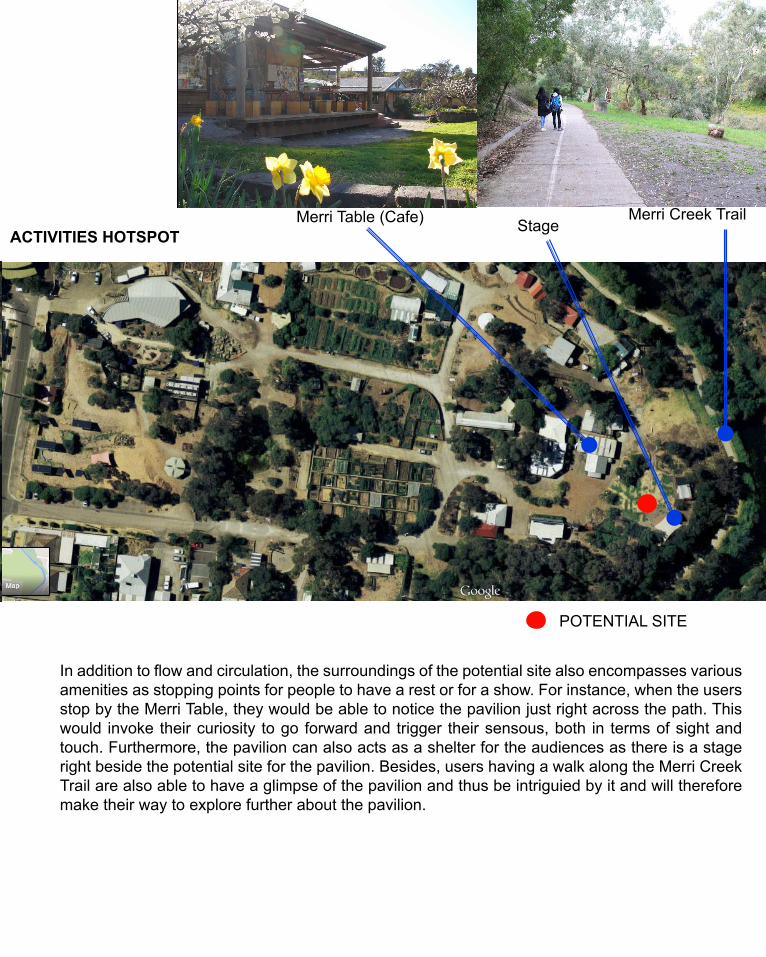
As we were walking along the Merri Creek Trail, it is the CERES environmental park where we find that there are most activities happening on site. As our design concept was to build a pavilion to educate and allow users to understand natural materials at a one to one scale, the pavilion needs to be located along areas that are easily noticible and is able to evoke curiousity on passer-bys. Therefore, upon analysis, we found that while the CERES environmental park has two entrance, i.e. from the main road and from the Merri Creek Trail, there is an intersection point where users from both entrances would need to pass by. Therefore, it is chosen as the potential site for the pavilion.
POTENTIAL SITE
ACTIVITIES HOTSPOT
POTENTIAL SITE POTENTIAL SITE
In addition to flow and circulation, the surroundings of the potential site also encompasses various amenities as stopping points for people to have a rest or for a show. For instance, when the users stop by the Merri Table, they would be able to notice the pavilion just right across the path. This would invoke their curiosity to go forward and trigger their sensous, both in terms of sight and touch. Furthermore, the pavilion can also acts as a shelter for the audiences as there is a stage right beside the potential site for the pavilion. Besides, users having a walk along the Merri Creek Trail are also able to have a glimpse of the pavilion and thus be intriguied by it and will therefore make their way to explore further about the pavilion.
Merri Table (Cafe) StageMerri Creek Trail
C1: DESIGN CONCEPTFORM FINDING
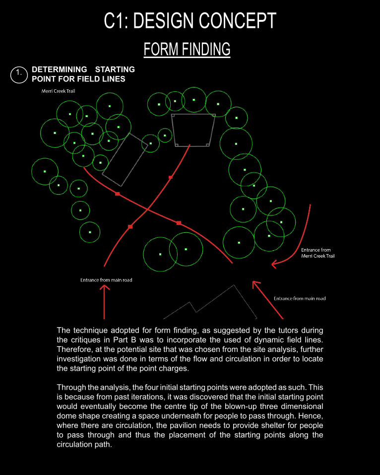
1. DETERMINING STARTING POINT FOR FIELD LINES
The technique adopted for form finding, as suggested by the tutors during the critiques in Part B was to incorporate the used of dynamic field lines. Therefore, at the potential site that was chosen from the site analysis, further investigation was done in terms of the flow and circulation in order to locate the starting point of the point charges.
Through the analysis, the four initial starting points were adopted as such. This is because from past iterations, it was discovered that the initial starting point would eventually become the centre tip of the blown-up three dimensional dome shape creating a space underneath for people to pass through. Hence, where there are circulation, the pavilion needs to provide shelter for people to pass through and thus the placement of the starting points along the circulation path.
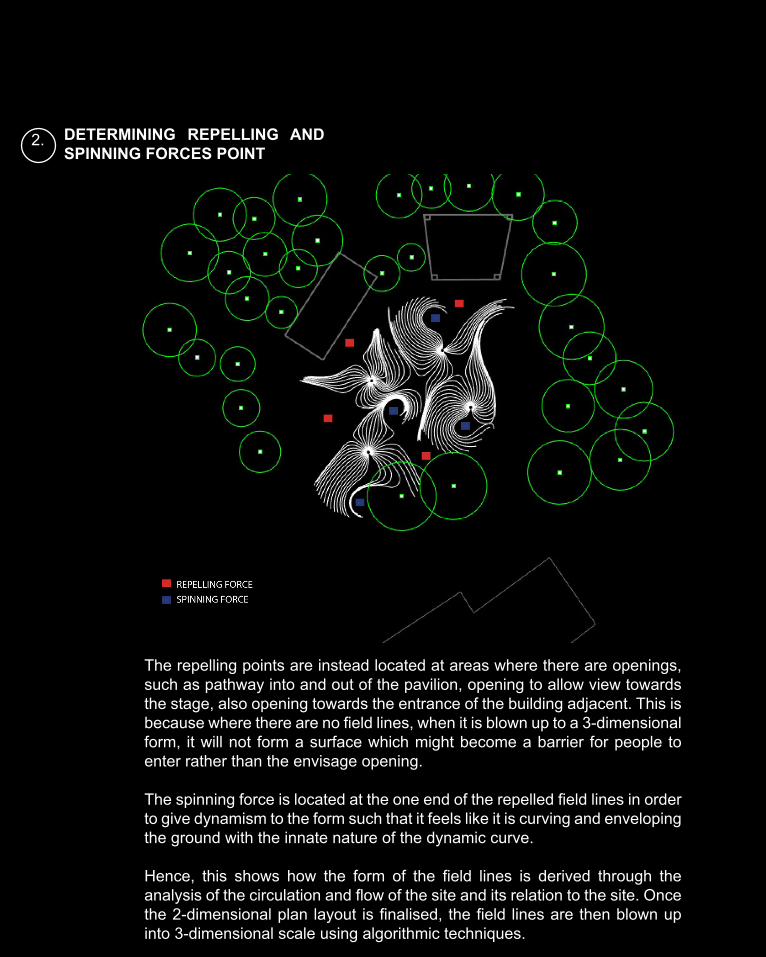
2. DETERMINING REPELLING AND SPINNING FORCES POINT
The repelling points are instead located at areas where there are openings, such as pathway into and out of the pavilion, opening to allow view towards the stage, also opening towards the entrance of the building adjacent. This is because where there are no field lines, when it is blown up to a 3-dimensional form, it will not form a surface which might become a barrier for people to enter rather than the envisage opening.
The spinning force is located at the one end of the repelled field lines in order to give dynamism to the form such that it feels like it is curving and enveloping the ground with the innate nature of the dynamic curve.
Hence, this shows how the form of the field lines is derived through the analysis of the circulation and flow of the site and its relation to the site. Once the 2-dimensional plan layout is finalised, the field lines are then blown up into 3-dimensional scale using algorithmic techniques.
C1: DESIGN CONCEPTFINAL ALGORITHMIC TECHNIQUE
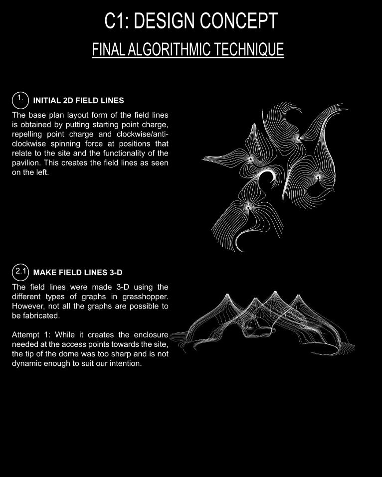
1. INITIAL 2D FIELD LINES
The base plan layout form of the field lines is obtained by putting starting point charge, repelling point charge and clockwise/anti-clockwise spinning force at positions that relate to the site and the functionality of the pavilion. This creates the field lines as seen on the left.
2.1 MAKE FIELD LINES 3-D
The field lines were made 3-D using the different types of graphs in grasshopper. However, not all the graphs are possible to be fabricated.
Attempt 1: While it creates the enclosure needed at the access points towards the site, the tip of the dome was too sharp and is not dynamic enough to suit our intention.
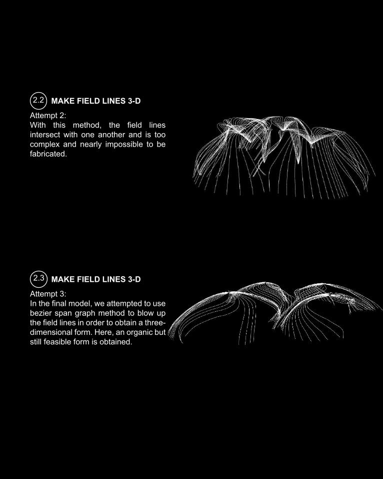
2.2 MAKE FIELD LINES 3-D
Attempt 2: With this method, the field lines intersect with one another and is too complex and nearly impossible to be fabricated.
2.3 MAKE FIELD LINES 3-D
Attempt 3:In the final model, we attempted to use bezier span graph method to blow up the field lines in order to obtain a three-dimensional form. Here, an organic but still feasible form is obtained.
C1: DESIGN CONCEPTFINAL ALGORITHMIC TECHNIQUE
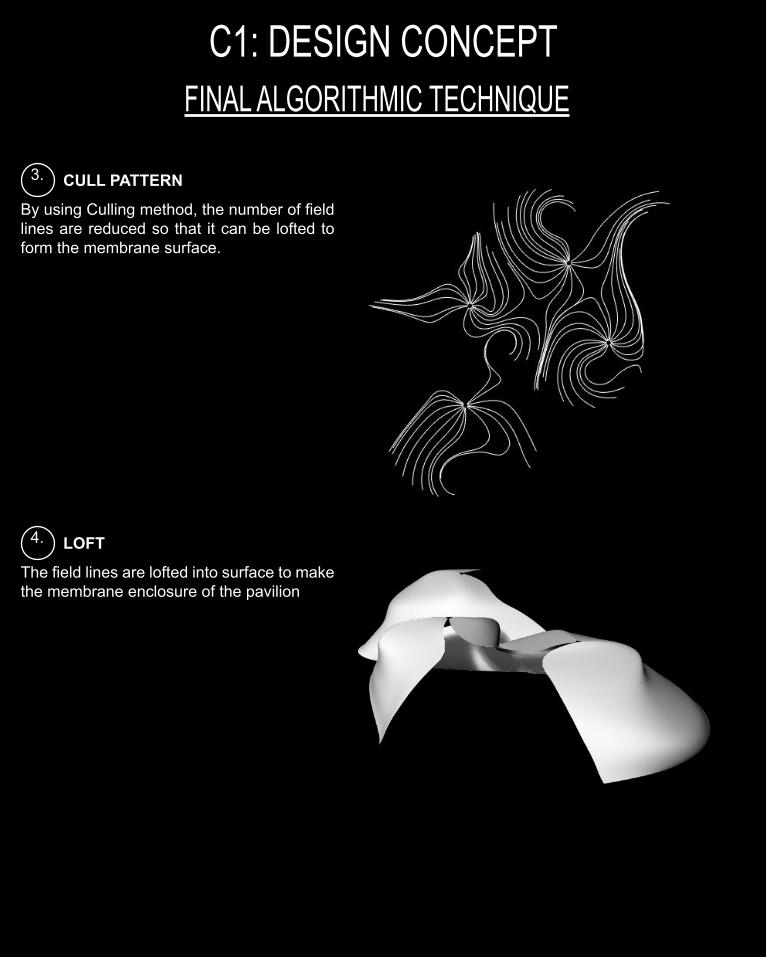
3. CULL PATTERN
By using Culling method, the number of field lines are reduced so that it can be lofted to form the membrane surface.
4. LOFT
The field lines are lofted into surface to make the membrane enclosure of the pavilion
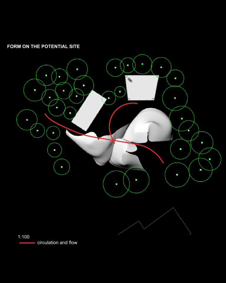
FORM ON THE POTENTIAL SITE
1:100 circulation and flow
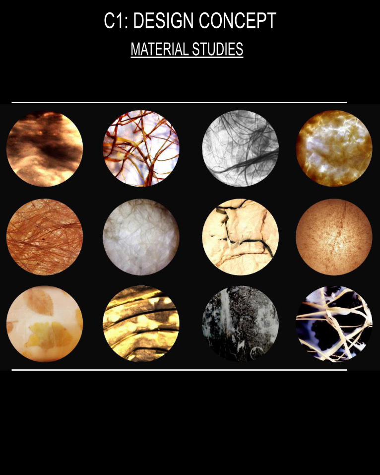
C1: DESIGN CONCEPTMATERIAL STUDIES
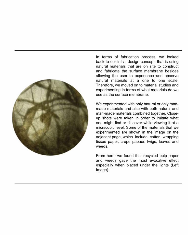
In terms of fabrication process, we looked back to our initial design concept, that is using natural materials that are on site to construct and fabricate the surface membrane besides allowing the user to experience and observe natural materials at a one to one scale. Therefore, we moved on to material studies and experimenting in terms of what materials do we use as the surface membrane.
We experimented with only natural or only man-made materials and also with both natural and man-made materials combined together. Close-up shots were taken in order to imitate what one might find or discover while viewing it at a micrscopic level. Some of the materials that we experimented are shown in the image on the adjacent page, which include, cotton, wrapping tissue paper, crepe papaer, twigs, leaves and weeds.
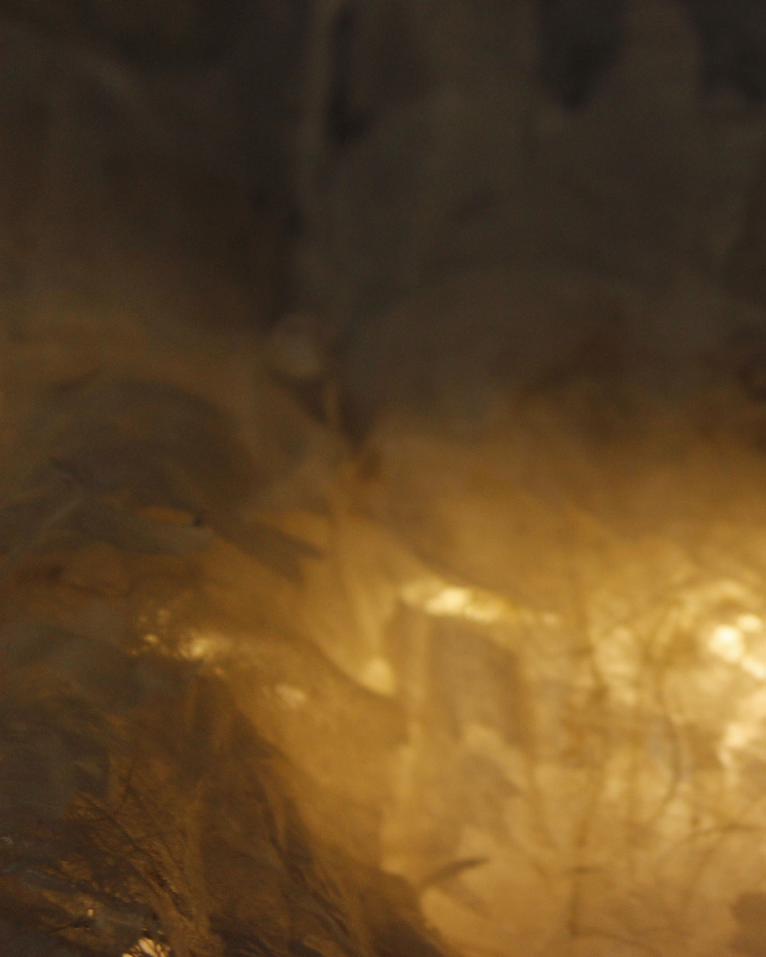
From here, we found that recycled pulp paper and weeds gave the most evocative effect especially when placed under the lights (Left Image).
C1: DESIGN CONCEPTMATERIAL STUDIES
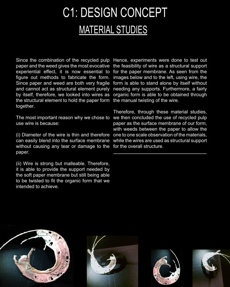
Since the combination of the recycled pulp paper and the weed gives the most evocative experiential effect, it is now essential to figure out methods to fabricate the form. Since paper and weed are both very fragile and cannot act as structural element purely by itself, therefore, we looked into wires as the structural element to hold the paper form together.
The most important reason why we chose to use wire is because:
(i) Diameter of the wire is thin and therefore can easily blend into the surface membrane without causing any tear or damage to the paper.
(ii) Wire is strong but malleable. Therefore, it is able to provide the support needed by the soft paper membrane but still being able to be twisted to fit the organic form that we intended to achieve.
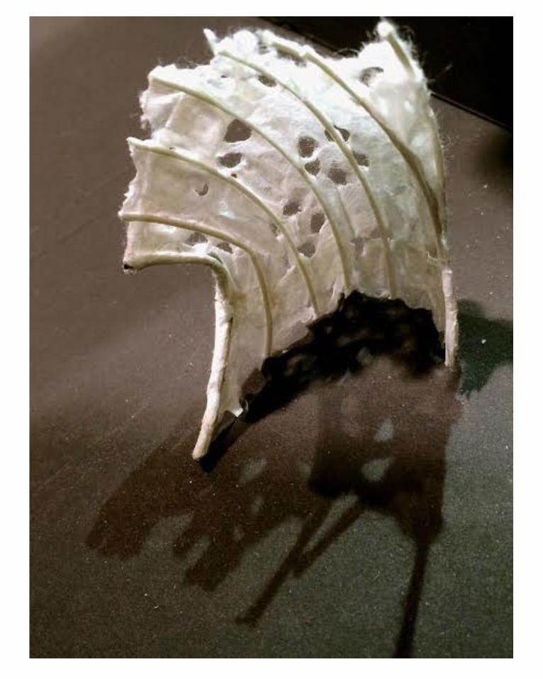
Hence, experiments were done to test out the feasibility of wire as a structural support for the paper membrane. As seen from the images below and to the left, using wire, the form is able to stand alone by itself without needing any supports. Furthermore, a fairly organic form is able to be obtained through the manual twisting of the wire.
Therefore, through these material studies, we then concluded the use of recycled pulp paper as the surface membrane of our form, with weeds between the paper to allow the one to one scale observation of the materials, while the wires are used as structural support for the overall structure.
C1: DESIGN CONCEPTCONSTRUCTION METHOD
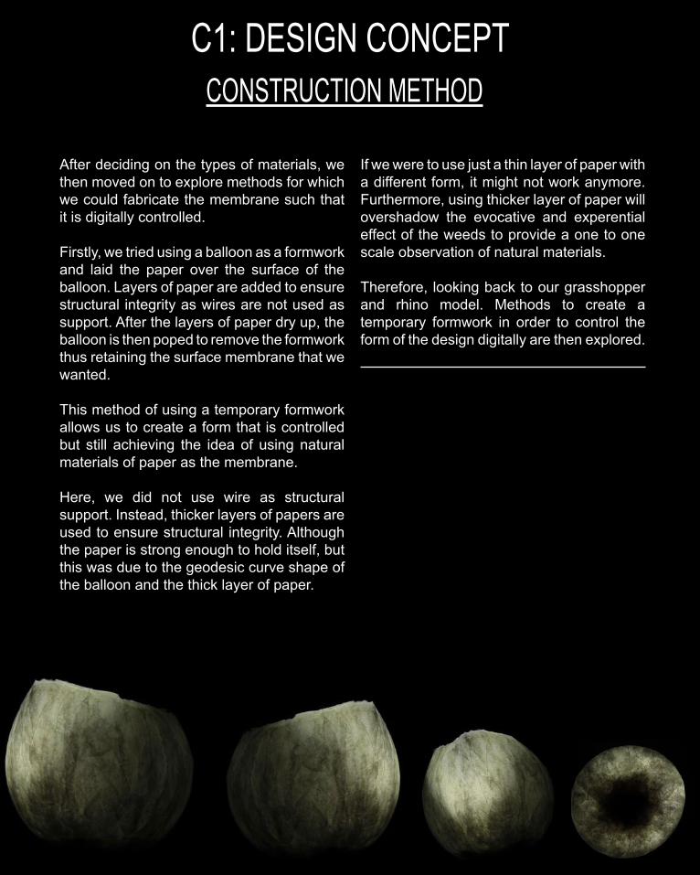
After deciding on the types of materials, we then moved on to explore methods for which we could fabricate the membrane such that it is digitally controlled.
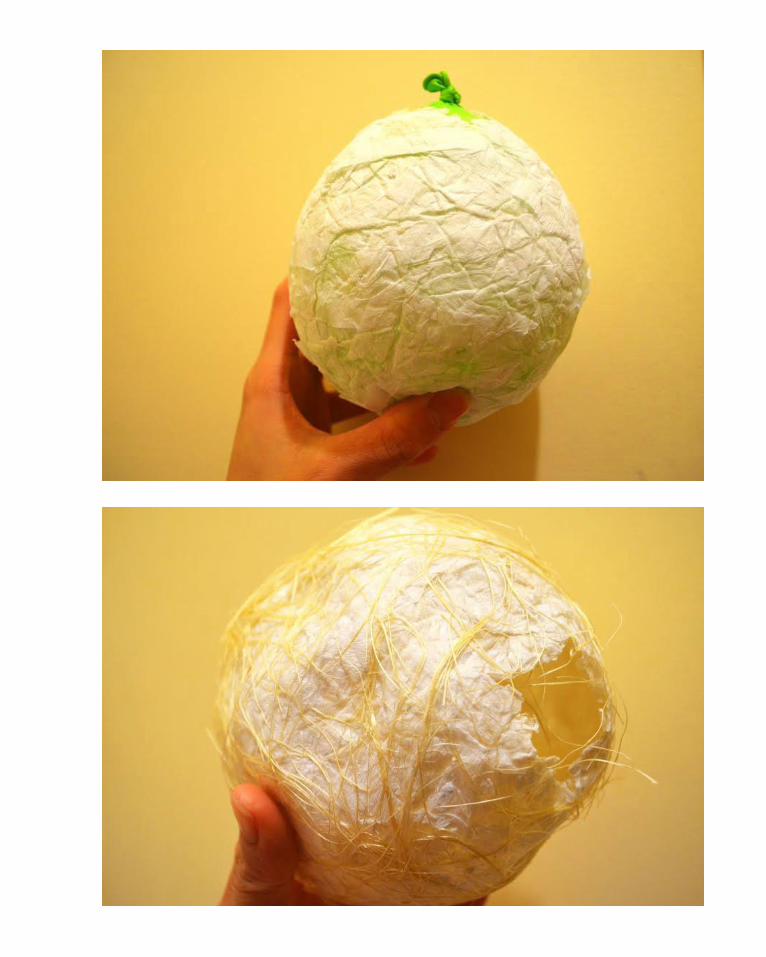
Firstly, we tried using a balloon as a formwork and laid the paper over the surface of the balloon. Layers of paper are added to ensure structural integrity as wires are not used as support. After the layers of paper dry up, the balloon is then poped to remove the formwork thus retaining the surface membrane that we wanted.
This method of using a temporary formwork allows us to create a form that is controlled but still achieving the idea of using natural materials of paper as the membrane.
Here, we did not use wire as structural support. Instead, thicker layers of papers are used to ensure structural integrity. Although the paper is strong enough to hold itself, but this was due to the geodesic curve shape of the balloon and the thick layer of paper.
If we were to use just a thin layer of paper with a different form, it might not work anymore. Furthermore, using thicker layer of paper will overshadow the evocative and experential effect of the weeds to provide a one to one scale observation of natural materials.
Therefore, looking back to our grasshopper and rhino model. Methods to create a temporary formwork in order to control the form of the design digitally are then explored.
C1: DESIGN CONCEPTPROPOSED CONSTRUCTION METHOD
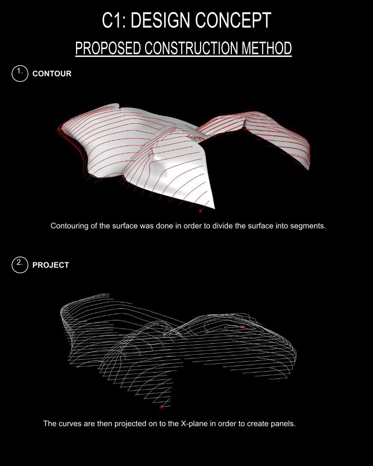
1. CONTOUR
Contouring of the surface was done in order to divide the surface into segments.
2. PROJECT
The curves are then projected on to the X-plane in order to create panels.
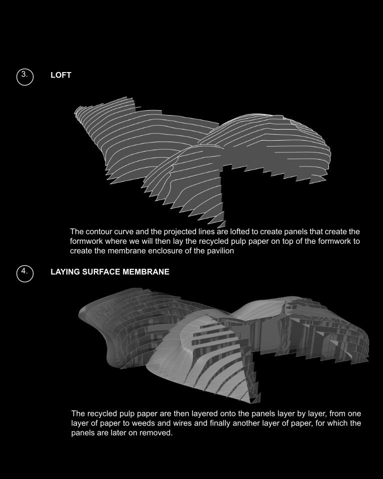
3. LOFT
The contour curve and the projected lines are lofted to create panels that create the formwork where we will then lay the recycled pulp paper on top of the formwork to create the membrane enclosure of the pavilion
4. LAYING SURFACE MEMBRANE
The recycled pulp paper are then layered onto the panels layer by layer, from one layer of paper to weeds and wires and finally another layer of paper, for which the panels are later on removed.
tectonic element & PROTOTYPE
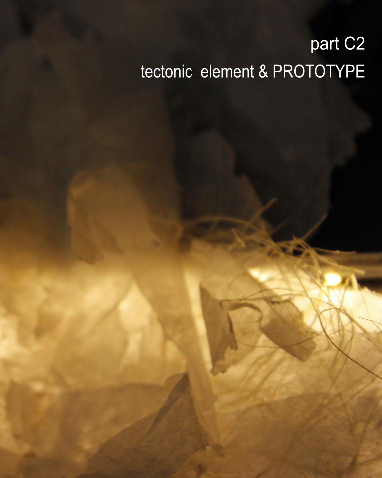
tectonic element & PROTOTYPEpart C2
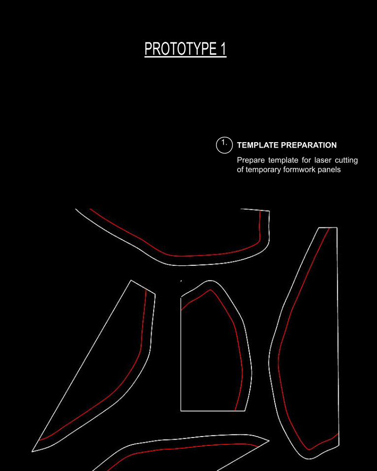
PROTOTYPE 1
1. TEMPLATE PREPARATION
Prepare template for laser cutting of temporary formwork panels
In our first prototype, we tried to test out the feasibility of the panels to act as temporary formwork for us to lay out the paper in a controlled form manner.
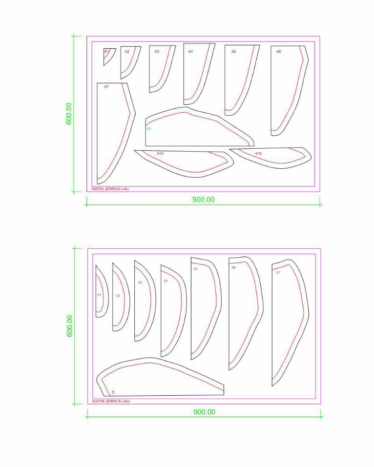
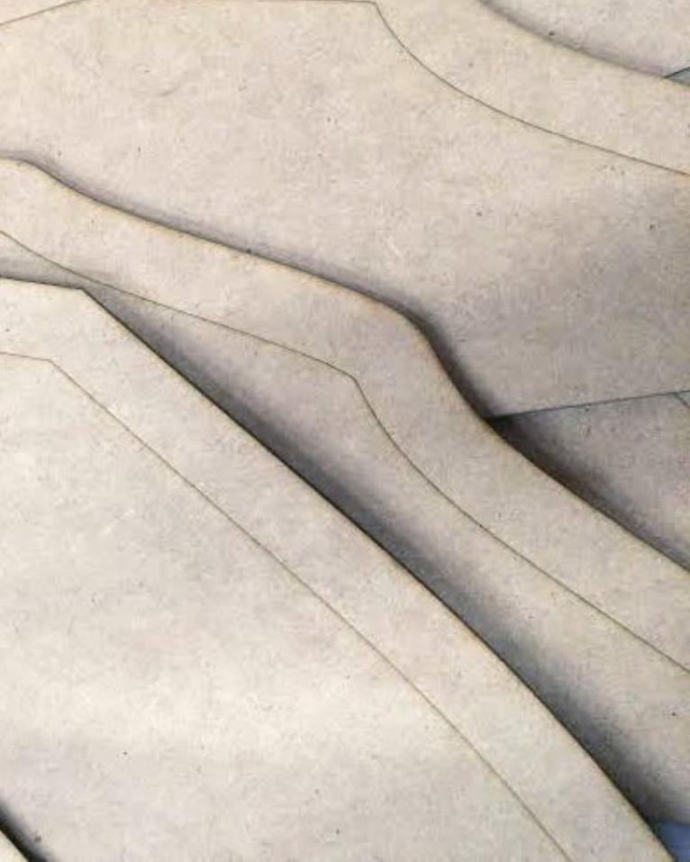
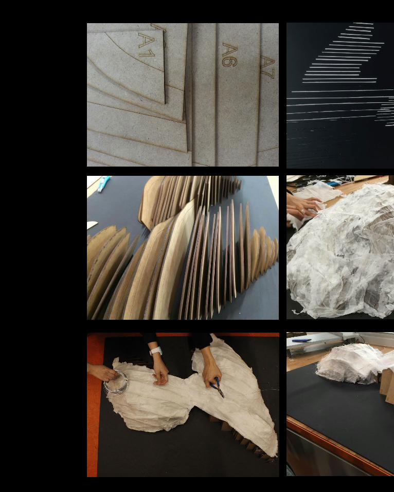
Firstly, the panels that was obtained through grasshopper were laid in the same plane and labelled to allow ease in identification during assembling stage. In terms of choice of materials of the panels, we needed materials which are not too thick so that the paper membrane can be easily removed, but also not too thin such that it cannot support itself. Therefore, we resorted with a 3.0mm MDF board as the material for the panels of the temporary formwork.
In addition, the slot to slide in the panels were also laser cutted on a thick board to act as the base of the formwork.
In terms of the assembly process, we first fix the panels onto the slots according to the labels and numberings of the panels. Once all the panels are slotted in, the first layer of papers are pasted onto the series of panels such that it follows the intended form. Due to concern about the structural integrity of the paper, we laid a few layers of paper before laying the weeds and wires on top of the paper. Then, another layer of paper are the pasted on top of the wire so as to hold the wire in place using the sandwich method.
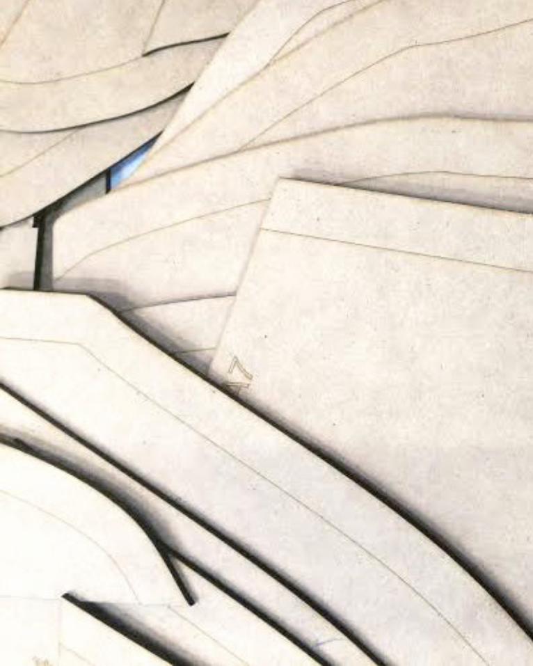
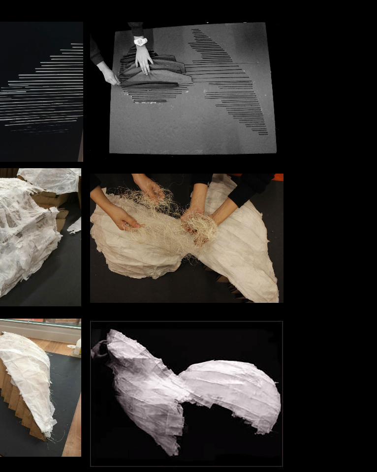
The laid materials (paper, weeds and wires) are left to dry overnight to ensure that the glue is holding the materials well enough to ensure structural integrity.
Lastly, the surface membrane of paper is then removed from the temporary formwork , for which it is held in place by the wire running longitudinally to the membrane.
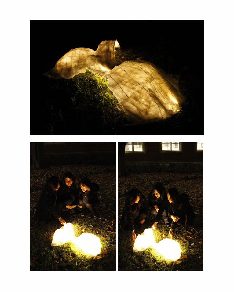
Strip lighting is used to light up the pavilion such that it would be able to allow the users to observe and discover the natural materials that are held within the paper strips at a one to one scale.
The effects of the lighting were tested out during the night and was found to be evocative. However, the weeds were not defined enough. Also, it was less dynamic than what we had in the field lines.
Therefore, in prototype 2, we tried to reduce the thickness of the paper layer in order to emphasise the weeds and also to project the field lines onto the membrane surface where the field lines represent the wire rather than just wires running in a longitudinal direction over the surface membrane.
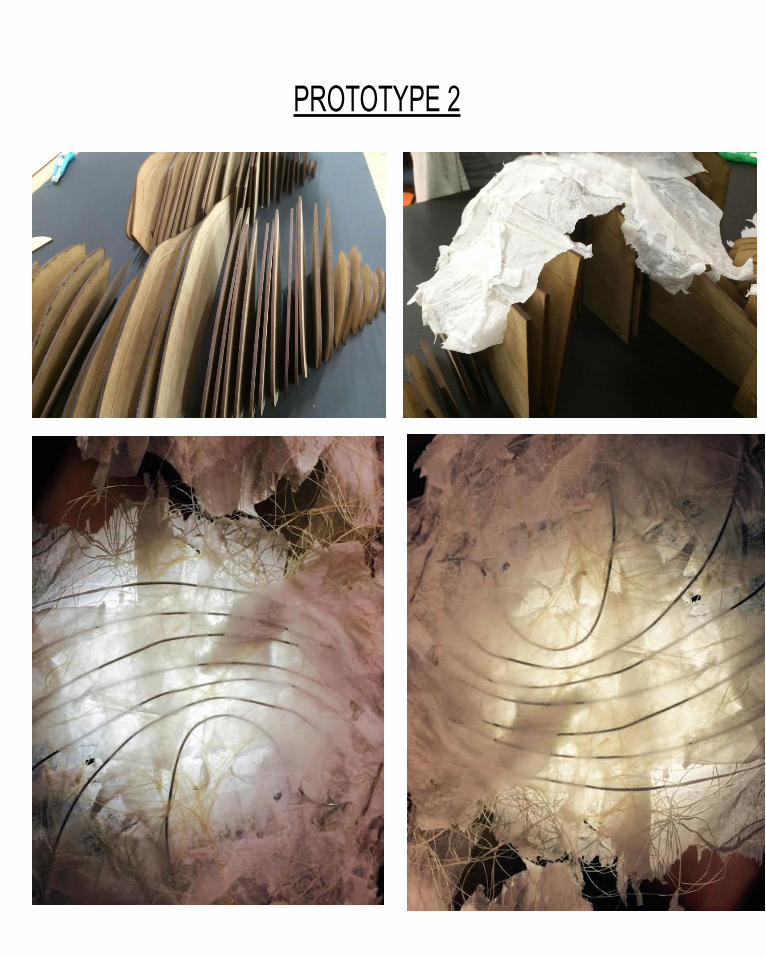
PROTOTYPE 2
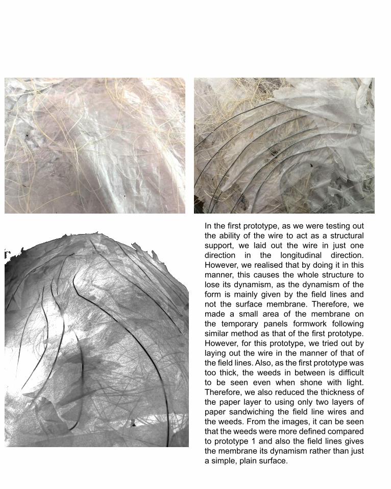
In the first prototype, as we were testing out the ability of the wire to act as a structural support, we laid out the wire in just one direction in the longitudinal direction. However, we realised that by doing it in this manner, this causes the whole structure to lose its dynamism, as the dynamism of the form is mainly given by the field lines and not the surface membrane. Therefore, we made a small area of the membrane on the temporary panels formwork following similar method as that of the first prototype. However, for this prototype, we tried out by laying out the wire in the manner of that of the field lines. Also, as the first prototype was too thick, the weeds in between is difficult to be seen even when shone with light. Therefore, we also reduced the thickness of the paper layer to using only two layers of paper sandwiching the field line wires and the weeds. From the images, it can be seen that the weeds were more defined compared to prototype 1 and also the field lines gives the membrane its dynamism rather than just a simple, plain surface.
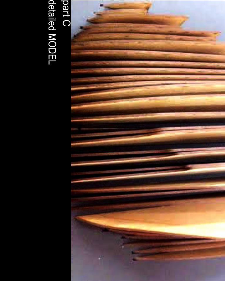
detailed MODEL
part C

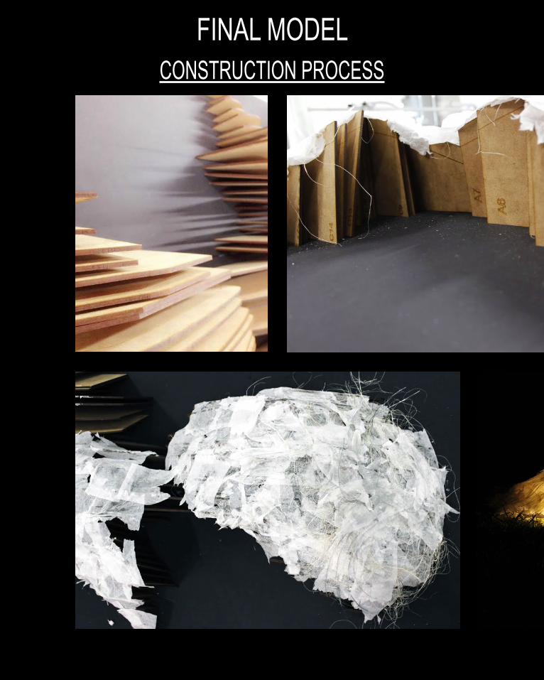
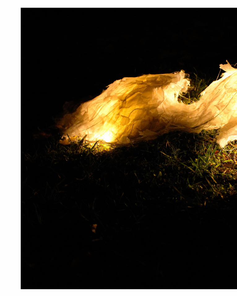
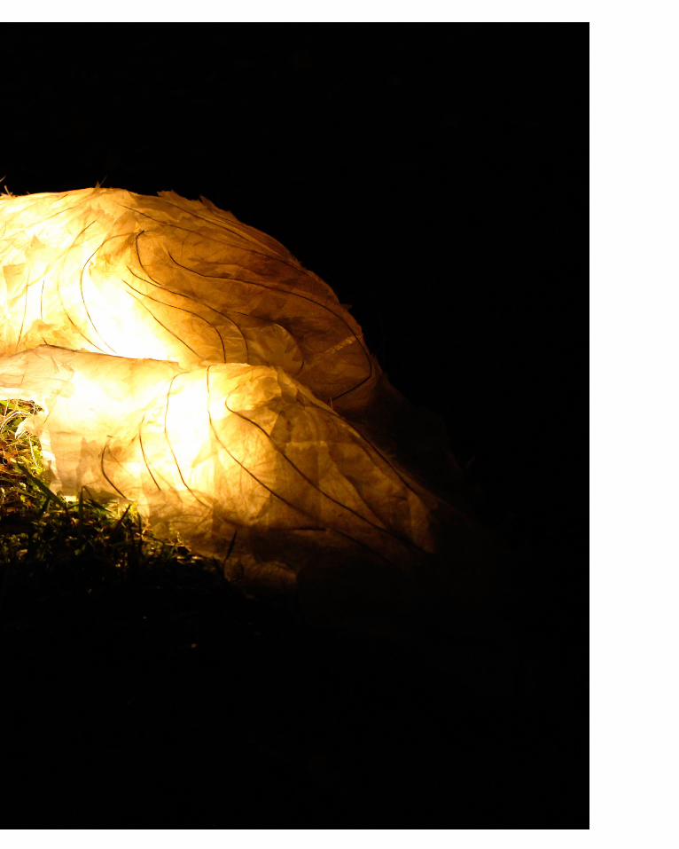
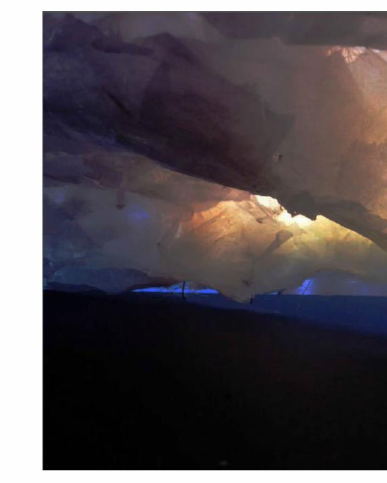
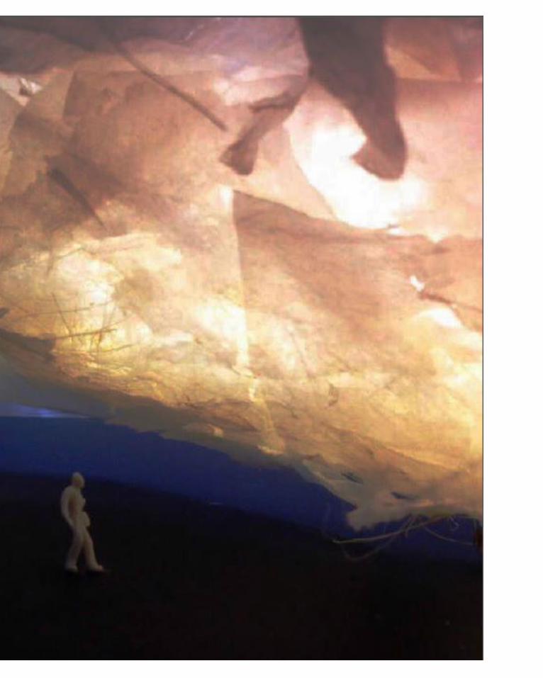
CONSTRUCTION PROCESSFINAL MODEL
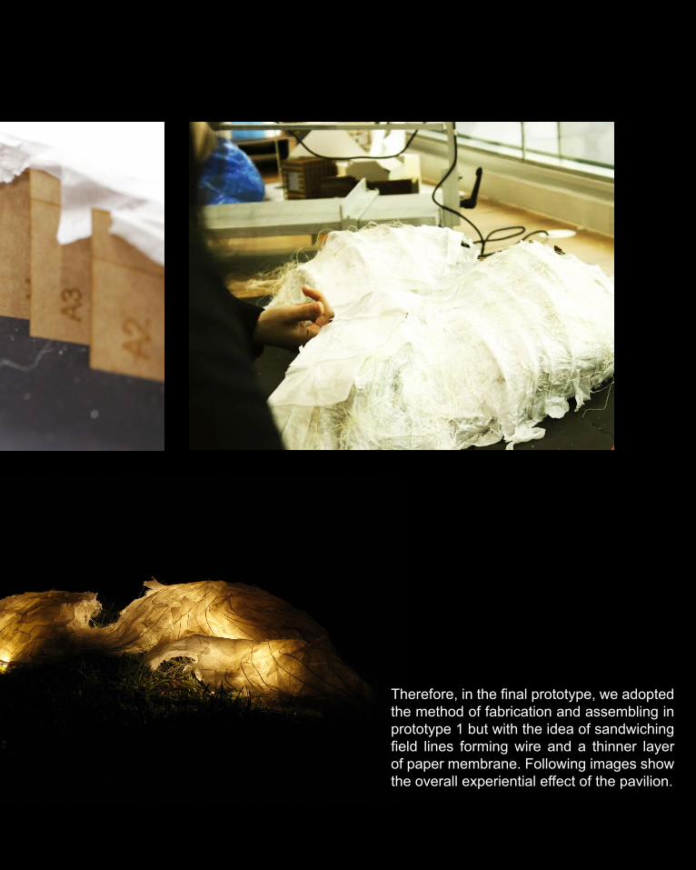
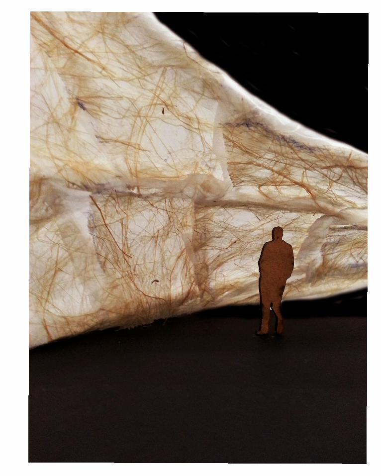
Therefore, in the final prototype, we adopted the method of fabrication and assembling in prototype 1 but with the idea of sandwiching field lines forming wire and a thinner layer of paper membrane. Following images show the overall experiential effect of the pavilion.
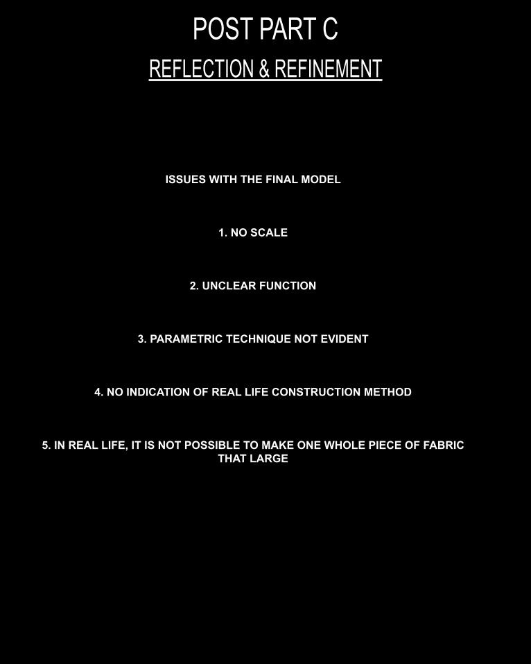
REFLECTION & REFINEMENTPOST PART C
ISSUES WITH THE FINAL MODEL
1. NO SCALE
2. UNCLEAR FUNCTION
3. PARAMETRIC TECHNIQUE NOT EVIDENT
4. NO INDICATION OF REAL LIFE CONSTRUCTION METHOD
5. IN REAL LIFE, IT IS NOT POSSIBLE TO MAKE ONE WHOLE PIECE OF FABRIC THAT LARGE
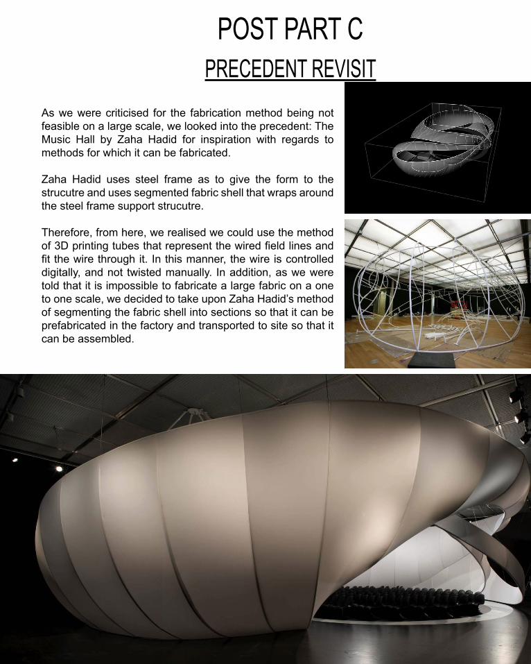
PRECEDENT REVISITPOST PART C
As we were criticised for the fabrication method being not feasible on a large scale, we looked into the precedent: The Music Hall by Zaha Hadid for inspiration with regards to methods for which it can be fabricated.
Zaha Hadid uses steel frame as to give the form to the strucutre and uses segmented fabric shell that wraps around the steel frame support strucutre.
Therefore, from here, we realised we could use the method of 3D printing tubes that represent the wired field lines and fit the wire through it. In this manner, the wire is controlled digitally, and not twisted manually. In addition, as we were told that it is impossible to fabricate a large fabric on a one to one scale, we decided to take upon Zaha Hadid’s method of segmenting the fabric shell into sections so that it can be prefabricated in the factory and transported to site so that it can be assembled.
REFLECTION & REFINEMENTPOST PART C
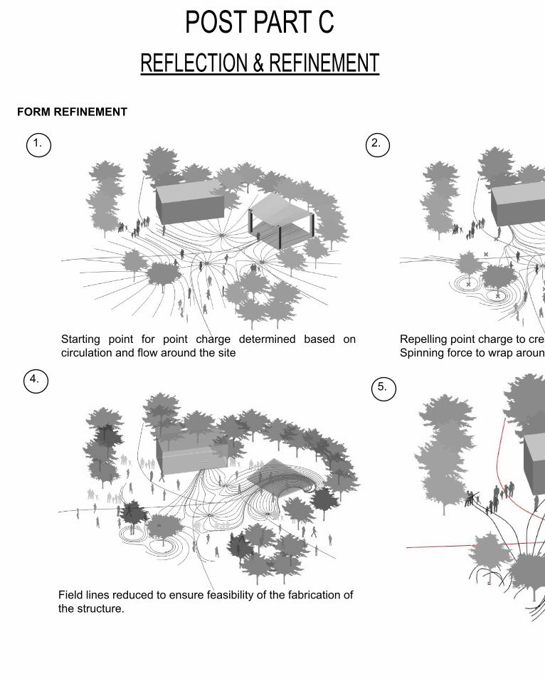
FORM REFINEMENT
1. 2.
4.5.
Starting point for point charge determined based on circulation and flow around the site
Repelling point charge to create openings.Spinning force to wrap around trees surrounding.
Field lines reduced to ensure feasibility of the fabrication of the structure.
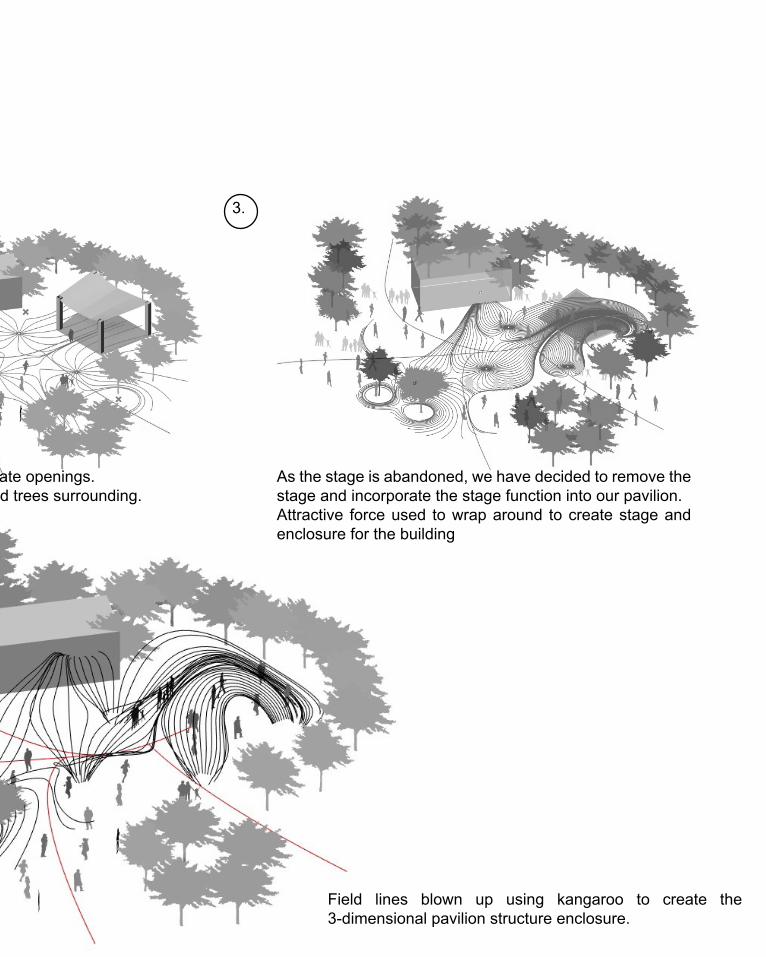
3.
Repelling point charge to create openings.Spinning force to wrap around trees surrounding.
As the stage is abandoned, we have decided to remove the stage and incorporate the stage function into our pavilion.Attractive force used to wrap around to create stage and enclosure for the building
Field lines blown up using kangaroo to create the 3-dimensional pavilion structure enclosure.
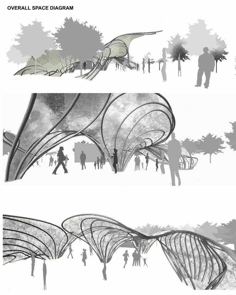
OVERALL SPACE DIAGRAM
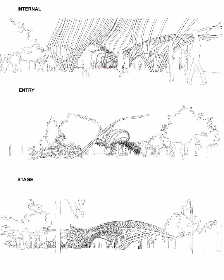
INTERNAL
ENTRY
STAGE
REFLECTION & REFINEMENTPOST PART C
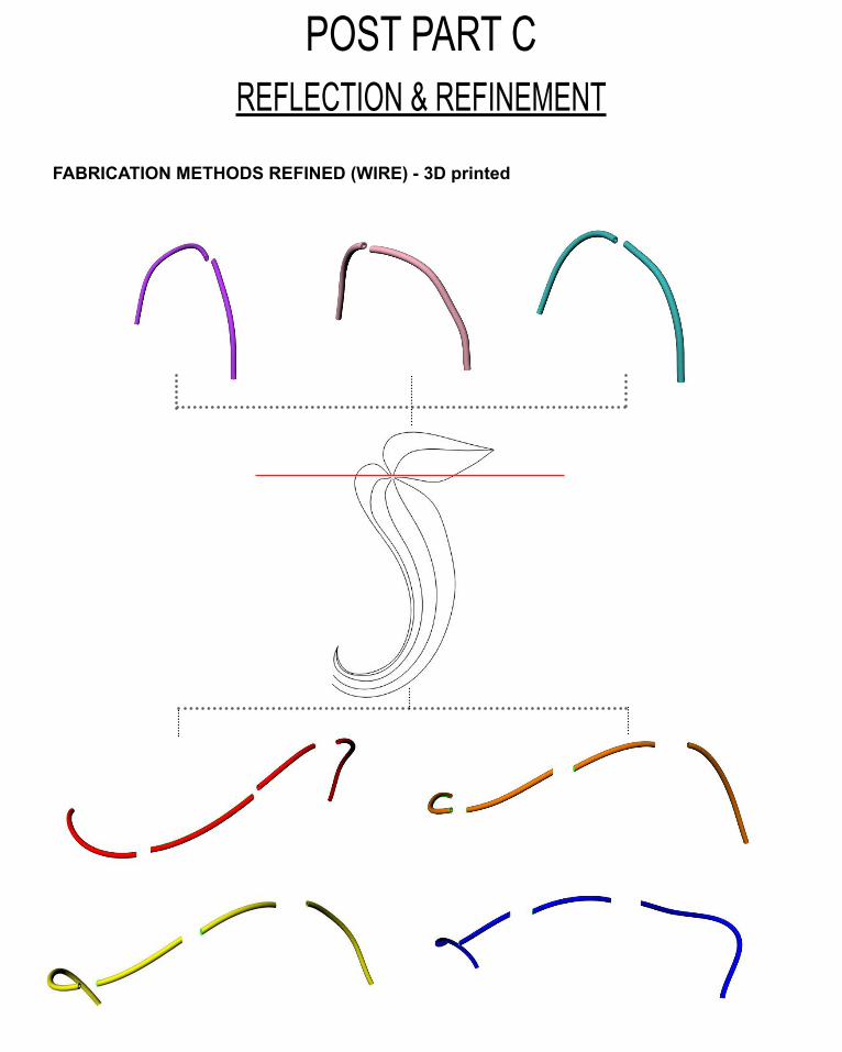
FABRICATION METHODS REFINED (WIRE) - 3D printed
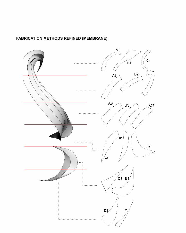
FABRICATION METHODS REFINED (MEMBRANE)
REFLECTION & REFINEMENTPOST PART C
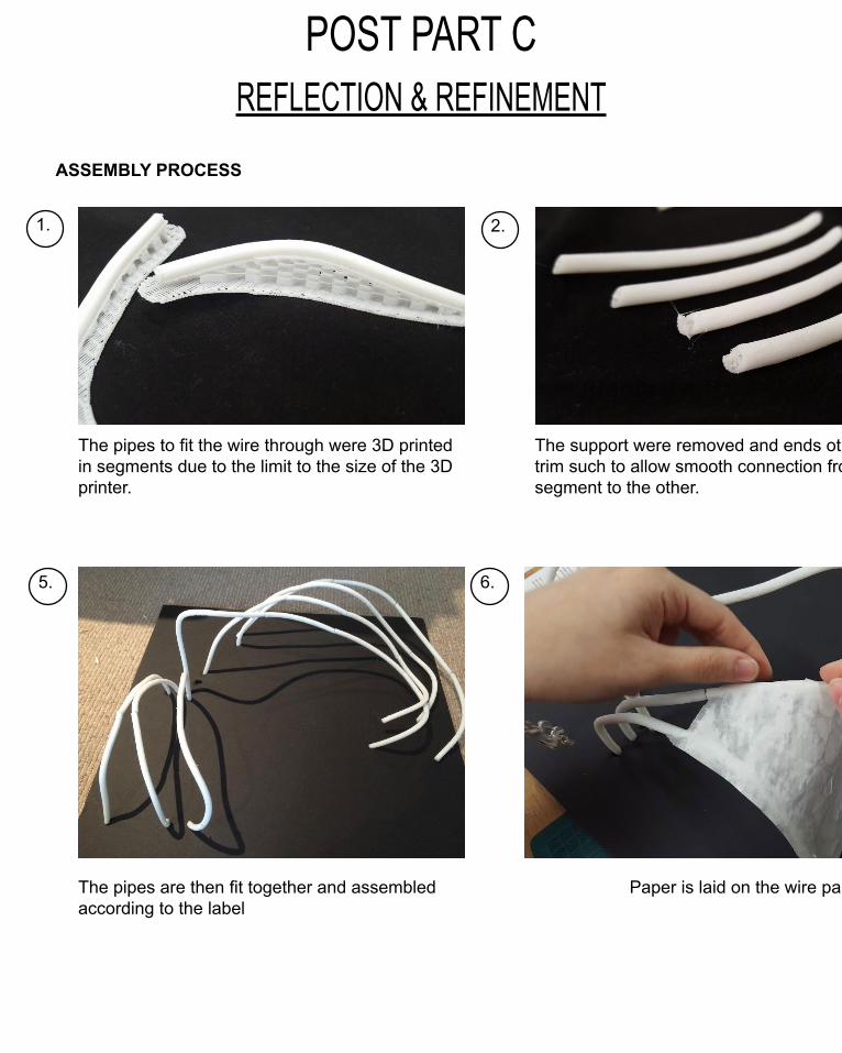
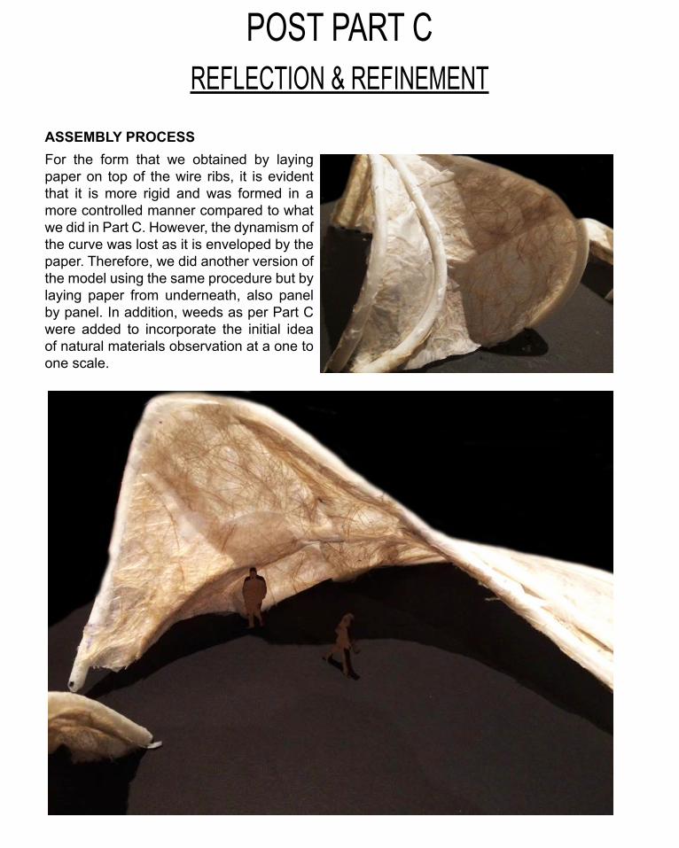
ASSEMBLY PROCESS
1. 2.
5.
The pipes to fit the wire through were 3D printed in segments due to the limit to the size of the 3D printer.
The support were removed and ends ot the pipe trim such to allow smooth connection from one segment to the other.
The pipes are then fit together and assembled according to the label
6.
Paper is laid on the wire panel by panel
3. 4.
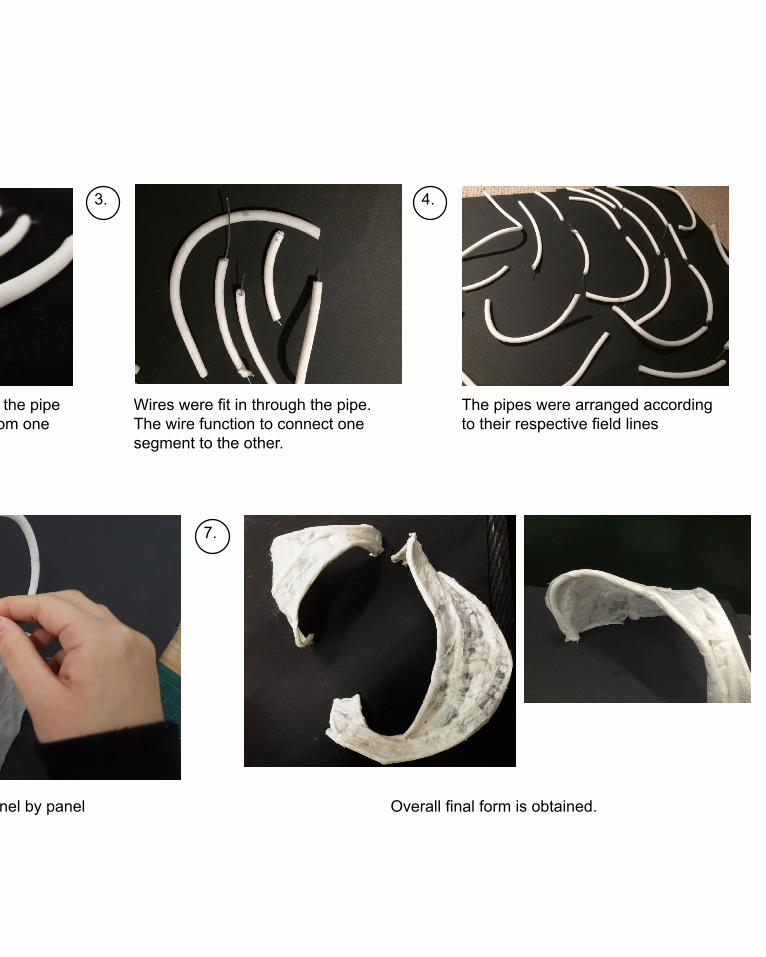
The support were removed and ends ot the pipe trim such to allow smooth connection from one segment to the other.
Wires were fit in through the pipe. The wire function to connect one segment to the other.
The pipes were arranged according to their respective field lines
Paper is laid on the wire panel by panel
7.
Overall final form is obtained.
REFLECTION & REFINEMENTPOST PART C
ASSEMBLY PROCESSFor the form that we obtained by laying paper on top of the wire ribs, it is evident that it is more rigid and was formed in a more controlled manner compared to what we did in Part C. However, the dynamism of the curve was lost as it is enveloped by the paper. Therefore, we did another version of the model using the same procedure but by laying paper from underneath, also panel by panel. In addition, weeds as per Part C were added to incorporate the initial idea of natural materials observation at a one to one scale.
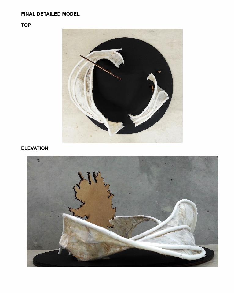
FINAL DETAILED MODEL
TOP
ELEVATION
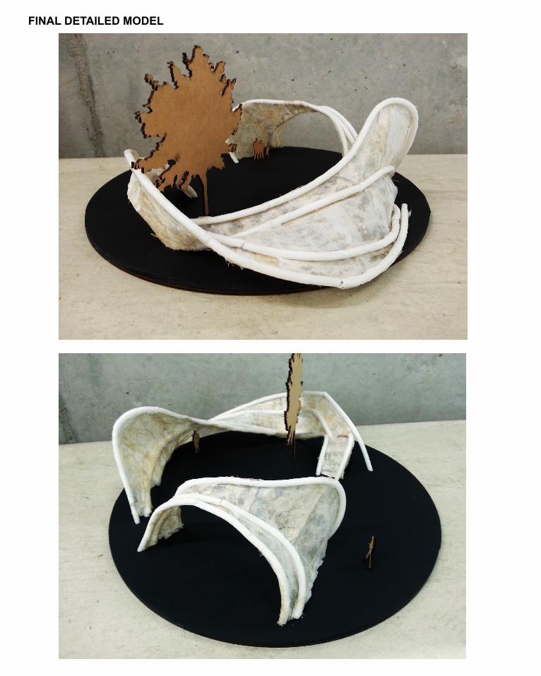
FINAL DETAILED MODEL
LEARNING OBJECTIVES & OUTCOME
Throughout the whole semester of Architecture Studio: Air, although on various aspects and terms, it was quite tough and stressful as someone who has little knowledge and exposure to parametric modelling and being unfamiliar with computer software, sitting through the whole semester, it turned out to be a fairly rewarding and fun learning process.
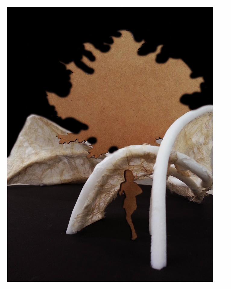
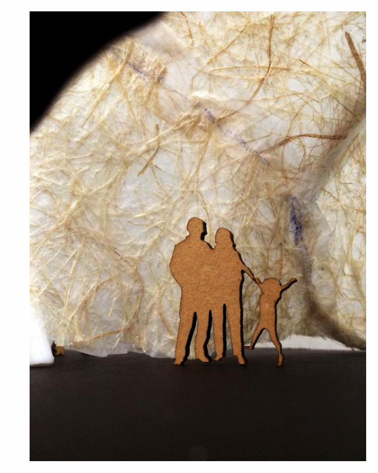
Being exposed to grasshopper and parametric modelling, I was able to explore the realm of computational modelling technique and realise the infinite possibilities provided by the software. For instance, using the technique of field lines and Kangaroo plug-in and setting various controlled settings such that it fits to the site and design proposal, many different evocative and dynamic outcomes that provide spatial interactions were able to be achieved. From here, the importance of scale and space in architecture is also realized.
Overall, Studio Air taught me a lot of different skills, from coming up with my own design proposal to site selection, computational modelling software and also brushed up on my skills in terms of layout and Adobe software. I am sure that the skills that I learned from this studio would be very beneficial throughout the course of architecture.
In addition, due to the large scale of the site and the open brief provided, on one hand, it allows flexibility and realm for creativity. On the other hand, analytical and selective skills are needed such that one is able to analyse and pick the site that suits the whole design proposal. Furthermore, this studio also pushes me to think about real life fabrication method, whether the designed project is feasible to be constructed in the real world, through the use of digital fabrication. This is a skill that was not obtained through previous studios which are more focused on design and conceptual aspect rather than real fabrication feasibility.
