studies of carbon{element bond forming reactions mediated
TRANSCRIPT

Studies of Carbon–Element Bond Forming Reactions Mediated by Complexes FeaturingUnsaturated Group 8 — Group 14 Interactions
By
Patrick William Smith
A dissertation submitted in partial satisfaction of the
requirements for the degree of
Doctor of Philosophy
in
Chemistry
in the
Graduate Division
of the
University of California, Berkeley
Committee in charge:
Professor T. Don Tilley, ChairProfessor John Arnold
Professor Donald J. DePaolo
Summer 2018


Abstract
Studies of Carbon–Element Bond Forming Reactions Mediated by Complexes FeaturingUnsaturated Group 8 — Group 14 Interactions
by
Patrick William Smith
Doctor of Philosophy in Chemistry
University of California, Berkeley
Professor T. Don Tilley, Chair
Chapter 1 Fundamental aspects of transition metal–Si chemistry are discussed, par-ticularly in the context of silylene complexes. A discussion of the basic aspects of Si chem-istry, namely the much lower electronegativity of Si vs. C, leads to the conclusion thatparticularly for late transition metal–Si bonds the bond may be polarized toward the metal,leading to a partial positive charge at Si in such molecules. This, along with the inherentweakness of π–bonding to Si, explains the high degree of electrophilicity often observed forsilylene complexes. Electrophilic Si centers bound to transition metals have a tendency tointeract with other, negatively charged ligands (in particular hydrides), forming nonclas-sical, delocalized bonding motifs. Because of this, Si—H bond activations often define acontinuum, in contrast to the well–defined bond activations observed for C–based systems.
Chapter 2. This Chapter details reactions of the iron allyl complex Cp∗(iPr2MeP)-Fe(η3−C3H5) (2.1) with sterically demanding silanes. These reactions lead to stoichiometrichydrosilation of the allyl ligand, and dehydrocoupling reactions between the silane and theallyl group. Furthermore, this system has allowed access to a Si—H oxidative addition-reductive elimination equilibrium involving Cp∗(iPr2MeP)FeH2(SiH2DMP) (2.5) and Cp∗-(iPr2MeP)FeH(N2) (2.6), which was independently synthesized.
Chapter 3. The iron mesityl dimer [FeMes2]2 has provided access to half–sandwichiron complexes using two strategies involving a formal protonolysis of one Mes ligand. Inthe first strategy, initial, in situ formation of a monometallic “(L)FeMes2” is proceededby a reaction with Cp∗H to lose mesitylene and form Cp∗(L)FeMes (L = PiPr2Me, 3.2a;PPh3, 3.2b; dppe, 3.2c) complexes. In the second strategy, [FeMes2]2 is used to deprotonateIiPrHCl and form (IiPr)FeMesCl which then reacts with Cp∗K. These mesityl complexes arereadily derivatized by E—H reagents (E = H, Cl, Si) to introduce the donor atom, E.
1

Chapter 4. Two new base-free hydrosilylene complexes of iron were synthesized using
the novel starting material Cp∗(iPr2MeP)FeMes (3.2a). These Cp∗(iPr2MeP)Fe(H)SiHR (R= DMP, 4.5; R = Trip, 4.4) complexes are in equilibrium with the corresponding iron silylcomplexes, Cp∗(iPr2MeP)FeSiH2R, which for R = Trip can be trapped by N2 and char-acterized as Cp∗(iPr2MeP)Fe(N2)SiH2Trip (4.3). Unlike the Ru analogues, the Fe silylenecomplex with R = DMP is observed to undergo an intramolecular C—H activation involvingformal addition of a benzylic C— bond across the Fe—Si bond. This increased activity forbond activations is also observed for reactions with hydrogen, where Fe reacts faster than aRu analog to form the hydrogenation product, Cp∗(iPr2MeP)H2FeSiH2DMP (2.5).
Chapter 5. Cationic iron complexes [Cp∗(iPr2MeP)FeH2SiHR]+, generated and cha-racterized in solution, are efficient catalysts for the hydrosilation of terminal alkenes andinternal alkynes by primary silanes or SiH4 at low catalyst loading (0.1 mol %) and ambienttemperature to yield only the corresponding secondary silane product. Mechanistic inves-tigations indicate a mechanism similar to that of the homologous Ru–silylene system, witha lower–energy dissociative silane exchange (product release) accounting for higher rates ofreaction for Fe relative to Ru.
Chapter 6. The dihydridoruthenate, {[(solv)Na][Cp∗(iPr2MeP)RuH2]}2 (6.2, solv
= THF, Et2O), was synthesized from Cp∗(iPr2MeP)RuCl (6.1) and sodium triethylborohy-dride. Compound 6.2 was used to generate Cp∗(iPr2MeP)RuH equivalents by salt metathesiswith 6.1, which resonance Raman spectroscopy indicates is a mixture of the terminal dini-trogen complex, Cp∗(iPr2MeP)RuH(N2) (6.4), and diastereomers of the bridging dinitrogencomplex, [Cp∗(iPr2MeP)RuH]2(µ−N2) (6.5 and 6.6). Compound 6.2 also reacted with thelate transition metal chloride complexes [(COD)IrCl]2 and (IPr)CuCl to form novel hydride–bridged heterobimetallic complexes Cp∗(iPr2MeP)Ru(µ–H)2Ir(COD) (6.7) and Cp∗(iPr2-MeP)Ru(µ–H)2CuIPr(6.8) which feature weakened Ru—H interactions relative to 6.2.
Chapter 7. The hydridoruthenate {[(solv)Na][Cp∗(iPr2MeP)RuH2]}2 (6.2; solv =
THF, Et2O) has provided access to Ru metallostannylene Cp∗(iPr2MeP)RuH2SnDMP (DMP= 2,6-dimesitylphenyl) (7.1) and metalloplumbylene Cp∗(iPr2MeP)RuH2PbArTrip2 (ArTrip2
= 2,6-bis(2,4,6-triisopropylphenyl)phenyl) (7.2) compounds by salt metathesis reactions withthe corresponding [ArEX]2 precursors. The Sn complex 7.1 reacted cleanly with MeI as anucleophile to generate the addition product Cp∗(iPr2MeP)RuH2SnI(Me)DMP (7.3) whilea complex mixture was observed for Pb. A Ru monohydride synthon generated from 6.2also provided access to the chlorostannylene and bromoplumbylene complexes Cp∗(iPr2-MeP)RuH(SnClDMP) (7.4) and Cp∗(iPr2MeP)RuH(PbBrArTrip2) (7.5), respectively. Thesecompounds have distorted trigonal planar geometries at Sn and Pb, with the Pb geometryvery nearly T–shaped. The electronic structures of these molecules were investigated usingdensity functional theory.
2

To my family: Rebecca, Harvest, Tom and Krista.
It is customary to regard the bonding of atoms from Li to Ne as normal and thus to considerthe behavior of the heavy elements as “abnormal”...it is rather the heavy elements whichbehave normally and not the more familiar elements of the first row.
–Werner Kutzelnigg
All you really need to know for the moment is that the universe is a lot more complicated thanyou might think, even if you start from a position of thinking its pretty damn complicated inthe first place.
–Douglas Adams
i

ii

Acknowledgments
Special thanks are due to my family. Rebecca and Harvest, whose support and love havebeen unfailing the last several years. Without you two this all would have been so much moredifficult. My parents, Thomas and Krista Smith, for welcoming us home and joining us onvacations when we needed to relax and, more importantly, for their support and belief in methroughout my childhood, B.S., and Ph.D. To my grandmother, Joan Schlax, who has beenthere for every important event in my life. My brother, Gavin, and my cousin, Kevin, whohave joined on adventures over the years. My extended family, especially those from SouthernCalifornia who welcomed me into their homes and lives while I was an undergraduate awayfrom home — Bob, Mindy, Ian, Shannon, and not least David, who (eventually) followed meto Berkeley.
I would like to thank my advisor, Don Tilley, who has allowed me to pursue chemistrywherever it has taken me, and whose advice and experience has provided invaluable contextand guidance. Thank you for encouraging the high quality of work that I hope this Disser-tation reflects; thanks also for the many enlightening discussions about chemistry and othersubjects during some excellent Faculty Club visits and around the fire at group camping trips.
The Tilley group has been a fulfilling and entertaining place to work for the last 6 years,due largely to Don’s eclectic taste in both chemistry and the people who do it. Thanks to allthe Tilley group from the years I’ve been here, and some from years past. Particularly, thosewith whom I shared 577 Tan: Allegra Lieberman–Martin, my longest companion; TrumanWambach, the nutty Canadian; Nick Phillips, partner in awful music; Rex Handford, thenuttier Canadian to whom the torch passes; and Miriam Bowring, Beatriz Brando, and JanaSchmitt. I would also like to thank silicon chemists from the group — those I worked with,Mark Lipke, Rick Liu, and Yuyang Dong; and those who laid the ground work, in particularPaul Hayes and Meg Fasulo. I want to specially thank Daniel Levine, who joined the groupwith me 6 years ago; since then I’ve been lucky to count him as a friend, both professionallyand personally. While I can’t possibly name all my friends from the group over the years,some have been particularly memorable: Gavin Kiel, Irene Cai, Ryan Witzke, Ben Suslick,Mike Lipschutz, Micah Ziegler, Andy Nguyen, Andrew Wijaya, and Raul Huerta–Lavorie,you all helped the days pass faster and more enjoyably, and have been instrumental in mydevelopment as a chemist. A second thanks is also due to Rex Handford for his invaluableaid in editing this document.
I am grateful to my undergraduate advisor, Josh Figueroa, without whom I not be here.Thank you so much for being an excellent mentor and for always going the extra mile to helpyour students succeed. Your exuberance and drive ignited my own passion for understandingthe way metals bond and behave, and made me realize how I actually want to spend my life.Also, it was iced tea, not Coke.
iii

Josh cultivated a group environment that required excellence from undergraduate as wellas graduate students; that experience was invaluable, and enriched by those I shared itwith: Julia Stauber, Tref Ditri, Alex Carpenter, Don Ripatti, Charles Mokhtarzadeh, NilsWeidemann, Alex Estrada, Liezel Labios, Steve George, Grant Margulieux, Matt Millard,and Brandon Barnett, who also followed me to Berkeley, eventually. Just get it done.
From Berkeley I would also like to thank Professors Richard Andersen and John Arnold,who have always been available for discussion and have helped guide my thinking aboutchemistry. A special thanks to everyone at UC Berkeley and LBL who have helped me realizemy experimental ideas — in particular the department facility managers and staff: KathyDurkin, Hasan Celik, Nanette Jarenwattananon, and David Smalls; and my collaborators,Stefan Minasian, Scott Ellis, Adam Schwartzberg, and Lorenzo Maserati. Thanks to myPh.D. cohort; particular thanks to my partners in crime, Matt Kapelewski and Nick Lewis,who were always there for an ill–advised night out.
Most of all, thank you for your interest and attention.
iv

Contents
1 An Introducton to Transition Metal Silylene Complexes 11.1 Bonding with Silicon . . . . . . . . . . . . . . . . . . . . . . . . . . . . . . . 21.2 Structure of Metal–Silicon Bonds . . . . . . . . . . . . . . . . . . . . . . . . 61.3 M—Si Single Bonds . . . . . . . . . . . . . . . . . . . . . . . . . . . . . . . . 111.4 Metal–Silicon Multiple Bonds: Silylene omplexes . . . . . . . . . . . . . . . . 151.5 Metal–bound Hydrides in Systems Featuring M—Si Interactions: Residual
Si—H bonding and Nonclassical Interactions . . . . . . . . . . . . . . . . . . 211.6 Summary . . . . . . . . . . . . . . . . . . . . . . . . . . . . . . . . . . . . . 291.7 References . . . . . . . . . . . . . . . . . . . . . . . . . . . . . . . . . . . . . 29
2 Silane–Allyl Coupling Reactions of Cp∗(iPr2MeP)Fe(η3–allyl) and Syn-thetic Access to the Hydrido–Dinitrogen Complex Cp∗(iPr2MeP)FeH(N2) 412.1 Introduction . . . . . . . . . . . . . . . . . . . . . . . . . . . . . . . . . . . . 412.2 Synthesis of Cp∗(iPr2MeP)Fe(η3 –allyl) and reactions with silanes . . . . . . 412.3 Hydrogenations of Cp∗(iPr2MeP)Fe(η3 –allyl) and isolation of the monohy-
dride complex Cp∗(iPr2MeP)FeH(N2) . . . . . . . . . . . . . . . . . . . . . . 452.4 Conclusion . . . . . . . . . . . . . . . . . . . . . . . . . . . . . . . . . . . . . 512.5 Synthetic Protocols . . . . . . . . . . . . . . . . . . . . . . . . . . . . . . . . 542.6 Crystallographic Structure Determinations . . . . . . . . . . . . . . . . . . . 582.7 References . . . . . . . . . . . . . . . . . . . . . . . . . . . . . . . . . . . . . 60
3 Synthetic Access to Coordinatively Unsaturated Iron Mesityl Complexesof the type Cp∗(L)FeMes 633.1 Introduction . . . . . . . . . . . . . . . . . . . . . . . . . . . . . . . . . . . . 633.2 Introduction of Cp∗ to Fe by Proton Transfer to [FeMes2]2 . . . . . . . . . . 643.3 Derivatization of Cp∗(L)FeMes Compounds . . . . . . . . . . . . . . . . . . . 693.4 Conclusion . . . . . . . . . . . . . . . . . . . . . . . . . . . . . . . . . . . . . 703.5 Synthetic Protocols . . . . . . . . . . . . . . . . . . . . . . . . . . . . . . . . 713.6 Details of X–ray Diffraction Experiments . . . . . . . . . . . . . . . . . . . . 733.7 References . . . . . . . . . . . . . . . . . . . . . . . . . . . . . . . . . . . . . 75
4 Base–Free Fe Hydrosilylene Complexes via an α–Hydride Migration thatInduces Spin Pairing 774.1 Introduction . . . . . . . . . . . . . . . . . . . . . . . . . . . . . . . . . . . . 774.2 Reactions of Cp∗(iPr2MeP)FeMes with silanes . . . . . . . . . . . . . . . . . 77
v

4.3 Characterization of α–H migration equilibria in Cp∗(iPr2MeP)HFe––EHR (E= Si, Ge; R = Trip, DMP) Complexes . . . . . . . . . . . . . . . . . . . . . 84
4.4 Reactivity of Fe Silylene Complexes Cp∗(iPr2MeP)HFe––SiHR (R = DMP, Trip) 87
4.5 Conclusions and Perspectives . . . . . . . . . . . . . . . . . . . . . . . . . . 88
4.6 Synthetic Protocols . . . . . . . . . . . . . . . . . . . . . . . . . . . . . . . . 88
4.7 Details of X–ray Diffraction Experiments . . . . . . . . . . . . . . . . . . . . 95
4.8 Computational Details . . . . . . . . . . . . . . . . . . . . . . . . . . . . . . 96
4.9 References . . . . . . . . . . . . . . . . . . . . . . . . . . . . . . . . . . . . . 98
5 Efficient and Selective Fe Hydrosilation Catalysis via Concerted DoubleSi—H Activation 101
5.1 Introduction . . . . . . . . . . . . . . . . . . . . . . . . . . . . . . . . . . . . 101
5.2 Catalytic Conditions and Substrate Scope . . . . . . . . . . . . . . . . . . . 102
5.3 Characterization of the Cationic Fe Catalysts . . . . . . . . . . . . . . . . . 105
5.4 Mechanistic Investigations . . . . . . . . . . . . . . . . . . . . . . . . . . . . 106
5.5 Conclusion . . . . . . . . . . . . . . . . . . . . . . . . . . . . . . . . . . . . . 111
5.6 Experimental Section . . . . . . . . . . . . . . . . . . . . . . . . . . . . . . . 113
5.7 Computational Details. . . . . . . . . . . . . . . . . . . . . . . . . . . . . . . 123
5.8 Silane Product Characterization Data. . . . . . . . . . . . . . . . . . . . . . 124
5.9 References . . . . . . . . . . . . . . . . . . . . . . . . . . . . . . . . . . . . . 126
6 An Anionic Ruthenium Dihydride [Cp∗(iPr2MeP)RuH2]– and its Conver-
sion to Heterobimetallic Ru(µ–H)2M (M = Ir, Cu) Complexes 131
6.1 Introduction . . . . . . . . . . . . . . . . . . . . . . . . . . . . . . . . . . . . 131
6.2 Synthesis and Characterization of New Homobimetallic Ruthenium Hydrides 132
6.3 Synthesis of Heterobimetallic Complexes . . . . . . . . . . . . . . . . . . . . 136
6.4 Conclusion . . . . . . . . . . . . . . . . . . . . . . . . . . . . . . . . . . . . . 138
6.5 Experimental Section . . . . . . . . . . . . . . . . . . . . . . . . . . . . . . . 138
6.6 Details of X–ray Diffraction Experiments . . . . . . . . . . . . . . . . . . . . 143
6.7 References . . . . . . . . . . . . . . . . . . . . . . . . . . . . . . . . . . . . . 144
7 Synthesis of Unsaturated Ru—Sn and Ru—Pb Complexes: Structure andBonding 149
7.1 Introduction . . . . . . . . . . . . . . . . . . . . . . . . . . . . . . . . . . . . 149
7.2 Synthesis and Characterization Complexes Featuring Unsaturated Ru—E In-teractions . . . . . . . . . . . . . . . . . . . . . . . . . . . . . . . . . . . . . 150
7.3 Structure and Bonding in Metallotetrylene and TetryleneComplexes . . . . . . . . . . . . . . . . . . . . . . . . . . . . . . . . . . . . . 160
7.4 Conclusion . . . . . . . . . . . . . . . . . . . . . . . . . . . . . . . . . . . . . 162
7.5 Experimental Section . . . . . . . . . . . . . . . . . . . . . . . . . . . . . . . 163
7.6 X–ray Diffraction Experiments. . . . . . . . . . . . . . . . . . . . . . . . . . 166
7.7 Computational Details . . . . . . . . . . . . . . . . . . . . . . . . . . . . . . 168
7.8 References . . . . . . . . . . . . . . . . . . . . . . . . . . . . . . . . . . . . . 168
vi

A Tables of Distances and Angles from X–ray Data 173A.1 Crystallographic Data Tables for Chapter 2 . . . . . . . . . . . . . . . . . . 173A.2 Crystallographic Data Tables for Chapter 3 . . . . . . . . . . . . . . . . . . 180A.3 Crystallographic Data Tables for Chapter 4 . . . . . . . . . . . . . . . . . . 185A.4 Crystallographic Data Tables for Chapter 6 . . . . . . . . . . . . . . . . . . 195A.5 Crystallographic Data Tables for Chapter 7 . . . . . . . . . . . . . . . . . . 203
vii

viii
List of Abbreviations and Terms
A Angstrom; 10−10 m
cm–1 Wavenumbers; a unit of energy
2D 2 dimensional
ArDipp2 2,6–bis(2,6–diisopropylphenyl)phenyl
ArTrip2 2,6-bis(2,4,6–triisopropylphenyl)phenyl
acac Acetylacetonate
allyl A propenyl fragment, with a designated hapticity η
Amp. Amplitude
AO Atomic orbital
BArF4 Tetrakis(pentafluorophenyl)borate
Bn Benzyl
c The coefficient of a single AO in a MO
COE Cyclooctene
Cp Cyclopentadienyl
Cp∗ Pentamethylcyclopentadienyl
Cpd. Compound
δ NMR chemical shift (ppm)
d An atomic orbital with an angular momentum quantum number of l = 2
Dipp 2,6–diisopropylphenyl
dippe Diisopropylphosphinoethane
DMP 2,6–dimesitylphenyl
dmpe 1,2-dimethylphosphinoethane
ix

dppe Diphenylphosphinoethane
dtbpe Di-tert-butylphosphinoethane
E Used in a chemical formula as a stand–in for a generic main group element;usually a tetragen.
η Hapticity of a ligand
Fc Ferrocene
Fc∗ Decamethylferrocene
Fp CpFe(CO)2
Fp∗ Cp∗Fe(CO)2
FWHM Full Width at Half Maxumum
G Gibbs free energy
HMPA Hexamethylphosphoramide
hydrosilation A reaction of an unsaturated organic fragment with a hydrosilane that re-sults in formal addition of the Si—H bond across a π bond. Also termedhydrosilylation.
Hz Hertz, a measure of frequency; s−1
IiPrHCl N,N–diisopropylimidazolium chloride
IiPr N,N-diisopropylimidazolylidene
IHI Interligand Hypervalent Interaction
IPr N,N-bis(diisopropylphenyl)imidazolylidene
iPr Isopropyl; 1–methylethyl
IR Infrared
IS Internal standard
IXy N,N–di(xylyl)imidazolylydene
κ Denticity of a ligand
kcal mol–1 Kilocalories per mole, a unit of energy
L A two–electron donor ligand.
l Angular momentum quantum number of an atomic orbital
x

M Used in a chemical formula as a stand–in for a metal; usually a transitionmetal
µ In a chemical formula, indicates a bridging ligand; also used for magneticmoment
M––Si A metal silicon double bond; the bond featured in a silylene complex
Me Methyl
Mes 2,4,6–trimethylphenyl
MO Molecular orbital
n Principal quantum number of an atomic orbital
NBO Natural bond orbital
NHC N–heterocyclic carbene
NMR Nuclear Magnetic Resonance
nPr n–propyl
o-C6H4 ortho–phenylene
p An atomic orbital with an angular momentum quantum number of l = 1
PES Photoelectron spectroscopy or potential energy surface
Ph Phenyl
Pos. Position
ppm Parts per million
Py Pyridine
primary In the context of a silane, a monohydrocarbyl silane (RSiH3)
QTAIM Quantum theory of atoms in Molecules
s An atomic orbital with an angular momentum quantum number of l = 0
SALC Symmetry–adapted linear combination
secondary In the context of a silane, a dihydrocarbyl silane (R2SiH2)
STP Standard temperature and pressure.
Tetragen An element in group 14 of the periodic table.
TMEDA N,N,N,N–tetramethylethylenediamine
xi

Trip 2,4,6–triisopropylphenyl
Tsi Trisyl, tris(trimethylsilyl)methyl
X A one–electron donor ligand.
Xyl 2,6-dimethylphenyl; xylyl
xii

Chapter 1
An Introducton to Transition Metal Silylene Complexes
By 2012 studies of multiple bonds between 4– or 5d transition metals and the heavy tetragens— Si, Ge, Sn, and Pb — had provided understanding about the structure and reactivity pat-terns in these molecules.1–7 Particularly close attention had been paid to silylene complexes,which feature metal–silicon double bonds and had been proposed as reactive intermediatesin several important catalytic cycles, most notably silane redistribution8 and hydrosilationcatalyzed by Rh9,10 or cationic silylene complexes.2,11–14 While early studies focused on devel-oping the synthetic chemistry associated with M––Si bonds, more recent work was focused onthe reactivity of silylene complexes in stoichiometic and catalytic transformations. Further-more, new examples of silylene complexes were increasingly featuring reactive substituentson Si such as hydrides and/or M–bound hydride ligands that may engage in migration chem-istry.
At that time, relatively little work had been reported on base–free 3d metal silylenecomplexes, despite the fact that many of the first donor–stabilized silylene complexes re-ported were Fe based, namely (CO)4FeSiMe2(NHMe2) (1.1),15 (CO)4FeSi(OtBu)2(HMPA)1.2,16 and Cp∗(CO)Fe(SiMe2)2(µ–OMe) (1.3).17 A compound formulated as (CO)4(SiMe3)-(H)Fe––SiMe2 was reported in 1978, though characterization of this complex was minimal.18
There was only one structurally characterized example of a 3d metal silylene complex, Cp∗-(CO)(SiMe3)Fe––SiMes2 (1.4),19 whose reactivity hinted that 3d metal silylene complexesmay have much more reactive silicon centers than their heavier analogues.
It was with this limited history of 3d metal–silylenes that the present work was under-taken beginning in 2012, with the goal of synthesizing 3d metal silylene complexes to betterunderstand their reactivity and the electronic differences between these rare complexes andtheir more common 4d and 5d homologues. The inital hypothesis was that there should bepoorer π bonding between the M and Si due to the more radially contracted 3d orbitals(relative to 4d and 5d), leading to enhanced electrophilicity at Si expected to promote newreactions not observed for heavier silylene complexes. Furthermore, greater ligand labilitydue to the overall weaker bonds 3d metals form with ligands (again, due to radial contractionof the 3d orbitals) was expected to lead to faster rates of reaction, potentially allowing forthe development of new catalytic processes. One factor that was not anticipated arises froma similar phenomenon: while in the heavier silylene complexes strong π bonding maintainsa large energy separation between the ground and excited states, overall weaker bonding inlighter metal compounds may allow for spin–crossover reactivity, which has been directlyobserved for α–H migrations in Chapter 4.
1
The target compounds originally chosen were Fe complexes of the type Cp∗(R3P)(H)-Fe––SiRR′, the homologous complexes to the related Cp∗(R3P)(H)M––SiRR′ (M = Os, Ru)complexes reported in 2006 and 2009 by Hayes and Tilley.20,21 These seemed to be excellenttargets for a number of reasons. First, the chemistry of Cp∗ with Fe is well–developed, whichshould allow for easy access to metal starting materials. Second, the presence of M– andpotentially Si–bound H substituents would allow for studying α–H migration processes andpotentially give access to new transformations at Si by exploiting the reactive Si—H bond.Finally, by completing the series of Os, Ru, and Fe homologs, a systematic analysis of thebonding and reactivity differences between 3d silylenes and their better–studied 4d and 5dcongeners could be performed, allowing for better insight into the reactivity that may beexpected from other 3d metal complexes with unsaturated M––Si interactions.
This introductory Chapter leads into these experimental studies by laying the groundworkfor understanding the chemistry of M––Si bonds in terms of their bonding and reactivity aswell as providing a broader historical perspective. In 1.1, the chemistry of Si will be discussedin terms of how Si may be seen to differ from its lighter, more familiar cousin C, while 1.2 willdiscuss the unique electronic properties of M—Si bonds. 1.3 will describe the synthesis andreactivity of M—Si single bonds, while 1.4 will describe the historical development and uniquereactions associated with silylene complexes. Finally, 1.5 will discuss unique features andcharacterization of systems featuring both silicon–based ligands and metal–bound hydrides,which often feature nonclassical bonding and continua of electronic structures.
1.1 Bonding with Silicon
The ground state electron configuration of Si is [Ne]3s23p2, analogous to the [He]2s22p2
ground state configuration of C. This leads to many chemical similarities between the twoelements, with organosilicon chemistry dominated by tetrahedrally coordinated species that,on the surface, resemble their carbon homologs. The differences in the reactivity of silane(SiH4) and methane (CH4) are enough to indicate organosilicon chemistry is not simply heav-ier organic chemistry, as methane is kinetically stable in air (in the absence of any sparking),while silane combusts spontaneously (and violently). Furthermore, while combustion of bothmethane and silane is thermodynamically favorable and gives products with the empiricalformula EO2, one product is a colorless gas and the other a colorless solid at STP; typi-cally encountered solid CO2 (dry ice) adopts a different structure than SiO2, and only underextreme conditions does CO2 adopt a quartzlike structure.22
Many of the differences between these elements can be understood in terms of the simplestaspects of chemistry. The larger radius of silicon with respect to carbon allows for highercoordination numbers, lowering the activation energies of associative mechanisms and evenallowing isolation of pentacoordinate and hexacoordinate silicon compounds.* Here, thelarger size of Si eases the steric crowding of the ligands about the Si center, enabling theincrease in coordination number. These examples also illustrate the increased Lewis acidity
*Sometimes termed “hypervalent” or “hypercoordinate” compounds; the ultility of “hypervalent” is atopic of debate, as it has implications about the nature of bonding in the molecule.23,24 A particularlysatisfying terminology for 5– and 6–coordinate Si that avoids implications about the nature of chemicalbonding can be found in German, Uber Silikone.25 Examples of such compounds are numerous, and havebeen reviewed extensively.26–29
2

of many silanes relative to their carbon congeners. While 5– and 6–coordination is largelyenabled by the increased size of silicon, the stability of these molecules is fundamentallyrelated to electronegativity differences between Si and C.
In the tetragens, and indeed all the p–block groups, the greatest change in electronega-tivity is seen between the second and third periods. While the origin of this electronegativitydifference is an emergent property of the orbitals involved in bonding (vide infra), the effectis to make Si much more able to act as a Lewis acid even when 4–coordinate, and to serve asthe central atom in electron–deficient multicenter bonds. Such Lewis acidity has been usedwith some success for catalytic transformations in e.g. hydrosilation reactions.30
Another manifestation of the electronegativity difference between Si and C is in bondpolarities. This is most noticeable in E—H bonds, as H is intermediate between Si andC in terms of electronegativity. This has the interesting effect of reversing the E—H bondpolarity upon moving from C to Si; H in a typical C—H bond carries a partial positive charge(a “protic” hydrogen) and in a typical Si—H bond H carries a partial negative charge (a“hydridic” hydrogen). This has a broad–reaching effect on the observed reactivity of silicon–based systems, and must be taken into account when formulating strategies to activate Si—Hbonds.14 It seems likely that the reversal in polarity between C—H and Si—H bonds leadsto a greater proclivity of silanes to add to transition metal centers, as they more readily formthe prerequisite σ–complexes.31–35
Orbital effects at Si. While useful as a concept for predicting reactivity and mostcommonly defined in terms of thermochemistry,36–38 ultimately electronegativity is an emer-gent property of the electronic structure of an atom. The origins of the different electroneg-ativities for the elements has commonly been rationalized in terms of differential shieldingof nuclear charge for orbitals involved in bonding. For the elements of the third period themarked decrease in electronegativity relative to the second period can be laid at the feet ofa large increase in the ratio of the radii of p to s orbitals.39,40 This results in better shieldingof 3p by 3s, lowering the ionization potential of the atom and contributing to a decrease inthe Mulliken electronegativity (relative to the second period);37,38 furthermore, the greaterspatial extent of 3p makes electrons located in these orbitals more polarizable,40 and overallmore capable of forming the highly polar (more ionic) bonds that form the basis for thePauling definition of electronegativity.36
This orbital origin of the sudden drop in electronegativity from the second to third periodis due to the ascent in the principal quantum number from n = 2 to n = 3, and is relatedto the structures of the s and p orbitals of the atoms. This results in a sharp decrease inthe ratio of the size of the s and p orbitals between the second and third period,* and canbe understood in terms of two contributing factors: a large increase in radius from 1s to2s, and a similar increase in radius from 2p to 3p. For both the 3p and 2s orbitals, theappearance of a radial node that was not present for the (n− 1)l orbital results in a greaterradial extension of the 3p orbital relative to 3s (Figure 1.1).39,40
This phenomenon is due to the presence of same–l core orbitals which, in order to main-tain orthogonality, necessitate greater radial extension of valence orbitals; this was termed“primogenic repulsion” by Pyykko,41 and has also been called “Pauli repulsion” as well as“Fermi repulsion”.40 For the second period elements, the presence of the 1s core electrons
*i.e. 3s/3p is smaller than 2s/2p
3
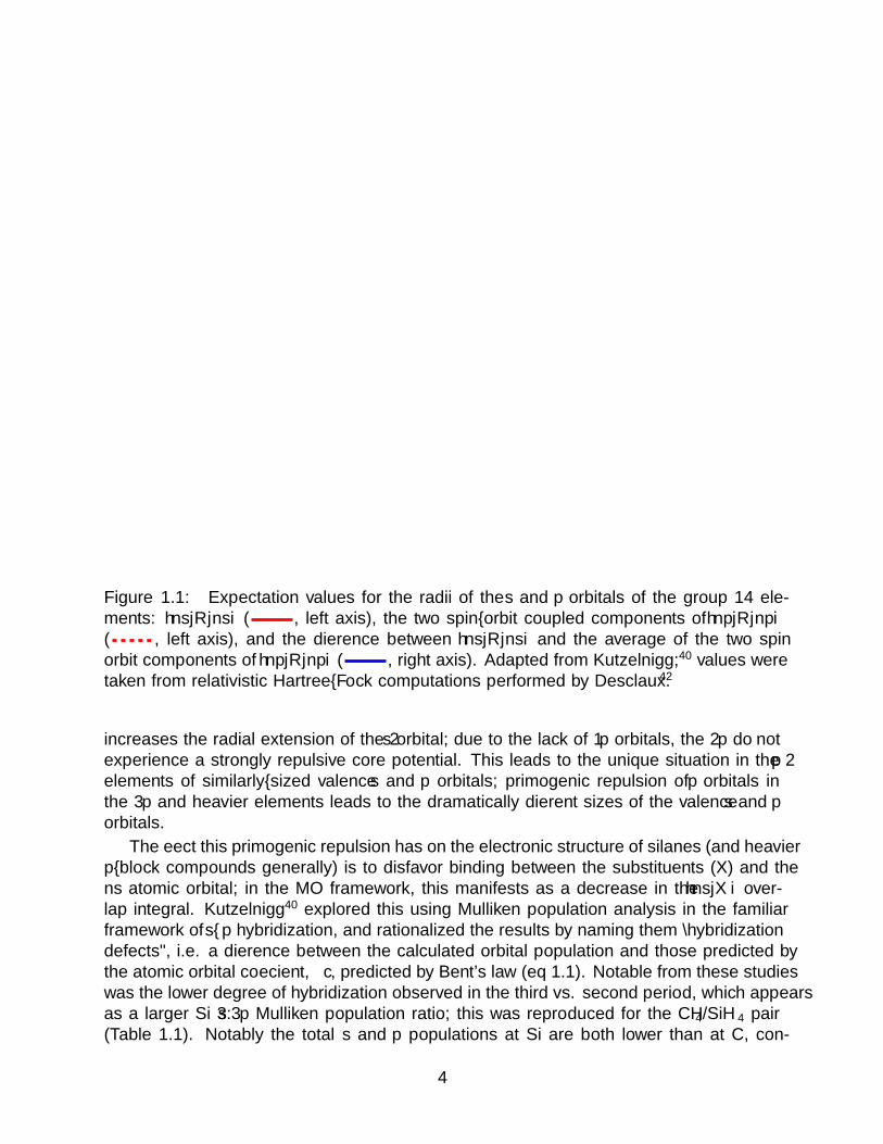
Figure 1.1: Expectation values for the radii of the s and p orbitals of the group 14 ele-ments: 〈ns|R|ns〉 ( , left axis), the two spin–orbit coupled components of 〈np|R|np〉( , left axis), and the difference between 〈ns|R|ns〉 and the average of the two spinorbit components of 〈np|R|np〉 ( , right axis). Adapted from Kutzelnigg;40 values weretaken from relativistic Hartree–Fock computations performed by Desclaux.42
increases the radial extension of the 2s orbital; due to the lack of 1p orbitals, the 2p do notexperience a strongly repulsive core potential. This leads to the unique situation in the 2pelements of similarly–sized valence s and p orbitals; primogenic repulsion of p orbitals inthe 3p and heavier elements leads to the dramatically different sizes of the valence s and porbitals.
The effect this primogenic repulsion has on the electronic structure of silanes (and heavierp–block compounds generally) is to disfavor binding between the substituents (X) and thens atomic orbital; in the MO framework, this manifests as a decrease in the 〈ns|X〉 over-lap integral. Kutzelnigg40 explored this using Mulliken population analysis in the familiarframework of s–p hybridization, and rationalized the results by naming them “hybridizationdefects”, i.e. a difference between the calculated orbital population and those predicted bythe atomic orbital coefficient, c, predicted by Bent’s law (eq 1.1). Notable from these studieswas the lower degree of hybridization observed in the third vs. second period, which appearsas a larger Si 3s :3p Mulliken population ratio; this was reproduced for the CH4/SiH4 pair(Table 1.1). Notably the total s and p populations at Si are both lower than at C, con-
4

sistent with the lower electronegativity.* This result makes sense from a molecular orbitalstandpoint; the Si 3s orbital is proportionally less involved in bonding and so localizes to Simore than 3p, and the overall electron density at Si is lower than C, reflecting the reversedpolarity of the Si—H bonds.
cosΘ =−c2
1− c2(1.1)
Table 1.1: NBO, Mulliken charges, and tet-ragen configurations caclulated at the ωB97-M–V/def2–TZVPP level of theory.
Cmpd. CH4 SiH4
QNBOE −0.84 0.64
QMulE −0.45 0.08
QNBOH 0.21 −0.16
QMulH 0.12 −0.02
E config.b 2s1.162p3.67 3s1.073p2.27
a taken as the average of the three E–boundH atoms.b atomic configuration taken from NBOanalysis of the Kohn-Sham orbitals.
Multiple bonding with Si. Asnoted previously, many organosilicon con-geners of common tetrahedrally–coordinatedorganic compounds are known. This, alongwith the group relationship between the twoelements, has led to some fanciful propos-als that life on other planets may be basedaround Si (rather than C).43,44 However,while tetrahedrally–coordinated Si is com-mon, trigonally–coordinated Si is quite rare,especially when compared to the plethora ofplanar C–based compounds. Biochemistryin particular employs trigonal C extensivelyfor structural purposes, where the high ro-tational barrier of π bonds imparts struc-tural rigidity not present in σ–only systems.Thus, without extensive use of rigid cagestructures, biochemistry based on Si wouldbe hard–pressed to replicate the rich structural diversity that enables carbon biochemistry.
The scarcity of trigonal organosilicon compounds, like other bonding changes from C toSi, can be traced to the addition of a radial part to the 3p wavefunction.39,40 The mostcommonly encountered rationalization based on this is that the overlap integral, 〈φA|φB〉,between two side–on p orbitals decreases much more rapidly down the group than for twoend–on p orbitals. A second factor is related to sterics; the longer bonds of elements in thethird vs. second period mitigate the repulsive interactions of substituents (or lone pairs) onneighboring atoms, which has the effect of weakening the σ–bonding in second period species(e.g. C2H6).40 Illustrating this, computational estimates for the strength of the π bond inSi2H4 place it at 22–26 kcal mol–1,45 while the Si2H6 Si—Si single bond strength is 81 kcalmol–1.46 For the carbon analogues, the C2H6 C—C bond energy of 88 kcal mol–1 is muchmore comparable to the C2H4 π–bond energy, which estimates place in the range of 60 kcalmol–1.46,47 This is also dramatically illustrated in molecules of groups 15 and 16, where theenergy of E—E σ–bonds can be seen to increase upon descending from the second to thirdperiod, an effect attributed to decreased lone pair–lone pair repulsion.40 Both of these effectslead to competitive π– and σ–bond energies in the second period, while for the third perioda much greater stabilization imparted by σ–bonds relative to π–bonds leads to preferencefor structures with a purely σ framework. A final factor affecting the stability of particularly
*An additional NBO analysis was also performed for comparison to Table 1.2; the results were consistentwith the Mulliken analysis.
5

E––E′ bonds* is the large orbital energy difference of the 2p and 3p orbitals. This leads toa highly polar π–bond, which lowers the kinetic barrier to aggregation and formation of aσ–framework by allowing e.g. polar cycloaddition reactions.
These factors are at the heart of the “classical double–bond rule”, which states that porbital based π bonding of elements with a principal quantum number greater than 2 shouldnot occur.48,49 Exceptions to this were first found in the 1970s for compounds of group 15elements.48 Si–based examples followed a few years later; in 1981 the conclusive observationand isolation of the first Si ––C50 and Si––Si51 compounds marked a turning point in the field,and explosive growth in the chemistry of multiply–bound Si soon followed.49,52–54 It should benoted that isolable examples of Si species featuring multiple Si––E bonds universally employsubstituents providing a large degree of steric protection to the unsaturated Si centers. Thisis to disfavor oligomerization reactions leading to e.g. silacyclic systems that trade therelatively weak Si double bonds for a bond in an extended σ framework.
1.2 Structure of Metal–Silicon Bonds
Bonding between Si and a metal center is largely well described by standard organometal-lic treatments of bonding. Silyls are analogous to alkyl ligands, for example, and as an Xtype ligand subtract one electron from a metal’s dn count. Silylene complexes, as the siliconanalogues of carbene complexes, can be treated as either an L type ligand with π acceptorqualities (as in e.g. Fischer or N–hetrerocyclic carbene complexes) or as an 2X type ligands(as in alkylidene complexes). In many cases, this simple treatment of M—Si bonding issufficiently predictive.
Metal–silicon single bonds. It has been observed that M—Si bonds are shorterthan expected from the Van der Waals radii of the involved atoms. This, along with their lowreactivity with respect to migratory insertion chemistry,55 was attributed to an increasedπ–backdonation from the metal (relative to alkyl ligands).56,57 This would be enabled bythe presence of primarily Si–based σ∗ orbitals� which are significantly extended toward themetal, in contrast to alkyl ligands where the σ∗ C—X orbitals are not as defined toward M,reducing the importance of π–backbonding. Some authors call this into question, however,citing the lack of bands in the PES attributable to M—Si π–bonding58 and the low degree ofπ–backbonding even in silyl groups with electronegative substituents.� 59 By analyzing PESand DFT results, the bond shortening (relative to expectated values) has most recently beenattributed to electrostatic effects of bond polarization.59
One interesting aspect of this bond polarization arises from the disparate orbital energies(and electronegativities) of C–based alkyl ligands and silyl ligands. In the latter, orbitalenergies are even more comparable to M–based orbitals, and the electronegativity of Si isintermediate to those of the transition metals.§ This has an important consequence in that
*Where E is a third period atom and E′ is a second period atom�Originally, it was proposed that Si–based 3d orbitals would constitute the Si centered π accepting
orbital; however, as with all main group elements, this has fallen out of favor due to the extremely highenergy of nd orbitals in the p block.
�M—Si π orbitals are calculated to account for only ca. 3 % of the bond strength in M–SiCl3§The electronegativity of Si is 1.8, while the transition metals range from 1.3 to 2.4; in the literature,
group electronegativities are often used for silyl ligands;57 however, without the corresponding group elec-tronegativities for the LnM fragments, it seems more useful to default to atomic electronegativities
6

Electropositive
M
Electronegative
MSi
Polarized towards Si Polarized towards M
Figure 1.2: Schematic representation of inversion of the ligand field for a M—Si bondupon moving from M with lower electronegativity (e.g. an early transition metal) to a metalwith higher electronegativity (e.g. a late transition metal). In the case of an electronegativemetal, the reversal in the primary atomic character of the bonding MO from Si to the Mleads to a consequent reversal in bond polarity.
M—Si bonds will not necessarily be polarized toward the ligand.59* Such an effect has beencalled an “inverted ligand field” and has been invoked previously in alkyl organometallicchemistry, typically for metals in high formal oxidation states;60,61 this is schematically illus-trated in Figure 1.2. In light of the lower electronegativity of Si than C, it seems reasonablethat this effect may manifest at lower formal metal oxidation states for silyl complexes.
To probe the potential for a reversal in M—E (E = C vs. Si) bond polarity, computationswere performed on a fragment that may exhibit just such an effect, the Fp complexes ofMe and SiH3. While the electronegativities of Fe and Si are competitive, the electron–withdrawing CO ligands may increase the group electronegativity of Fp enough to competewith SiH3 for electron density. The results of the NBO analysis of these complexes wereenlightening (Table 1.2). Most notable among these is the near reversal in Fe vs. E characterin the Fe—E bonding HOMO (from 40/60 for Fe—Me to 57/43 for Fe—SiH3). Consistently,while CMe carries a −0.81 charge, Si carries a nearly opposite 0.56 charge, with the chargeon the Fe center becoming increasingly negative upon replacement of Me with SiH3 (from-0.14 to -0.38). In addition to the reversal of polarity, it seems the magnitude of chargedifference between Fe and E in these systems increases from C to Si (|∆QFeC | = 0.67;|∆QFeSi| = 0.94), consistent with the proposal that M—Si bonds are shortened by increasedelectrostatic effects. It should finally be noted that based on these analyses, bonds between
*Consistent with this, many late–metal silyl complexes are prone to nucleophilic attack at Si; see 1.3
7
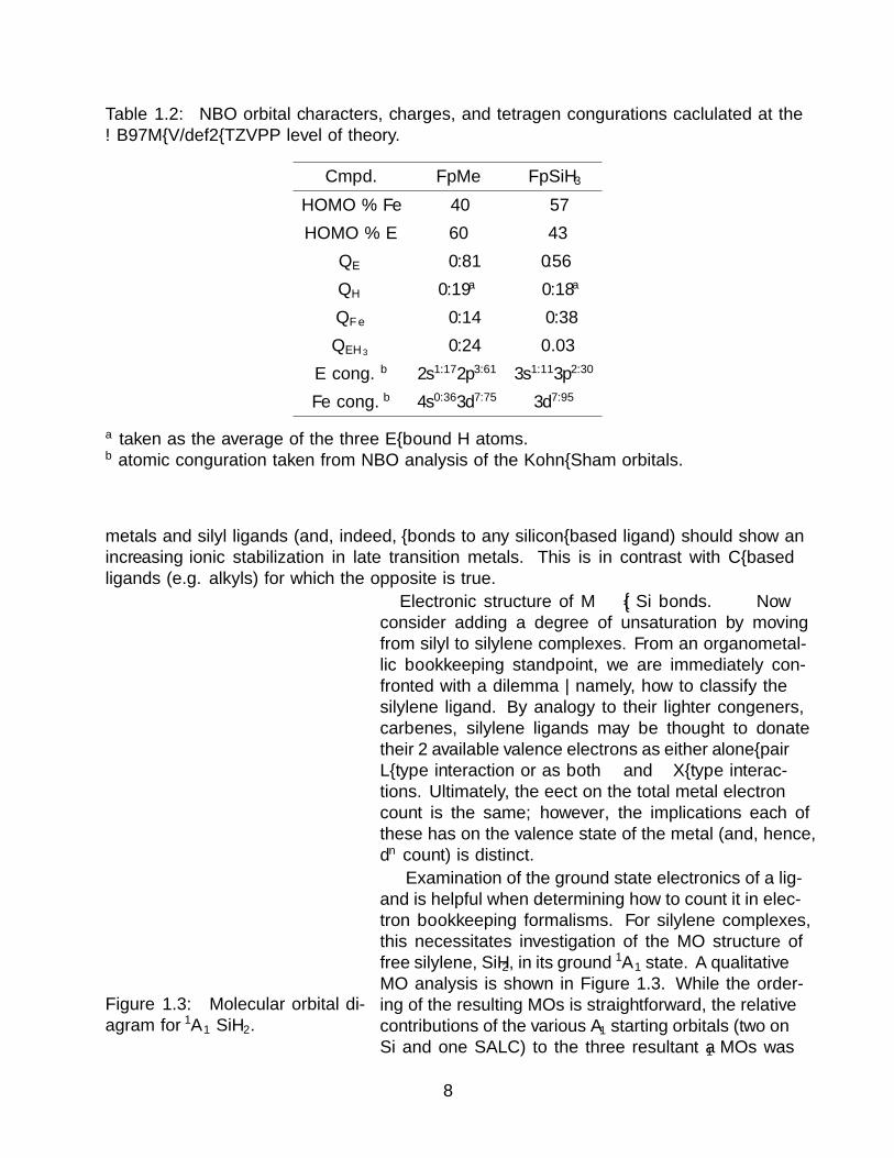
Table 1.2: NBO orbital characters, charges, and tetragen configurations caclulated at theωB97M–V/def2–TZVPP level of theory.
Cmpd. FpMe FpSiH3
HOMO % Fe 40 57
HOMO % E 60 43
QE −0.81 0.56
QH 0.19a −0.18a
QFe −0.14 −0.38
QEH3 −0.24 0.03
E config.b 2s1.172p3.61 3s1.113p2.30
Fe config.b 4s0.363d7.75 3d7.95
a taken as the average of the three E–bound H atoms.b atomic configuration taken from NBO analysis of the Kohn–Sham orbitals.
metals and silyl ligands (and, indeed, σ–bonds to any silicon–based ligand) should show anincreasing ionic stabilization in late transition metals. This is in contrast with C–basedligands (e.g. alkyls) for which the opposite is true.
Figure 1.3: Molecular orbital di-agram for 1A1 SiH2.
Electronic structure of M––Si bonds. Nowconsider adding a degree of unsaturation by movingfrom silyl to silylene complexes. From an organometal-lic bookkeeping standpoint, we are immediately con-fronted with a dilemma — namely, how to classify thesilylene ligand. By analogy to their lighter congeners,carbenes, silylene ligands may be thought to donatetheir 2 available valence electrons as either a σ lone–pairL–type interaction or as both σ and π X–type interac-tions. Ultimately, the effect on the total metal electroncount is the same; however, the implications each ofthese has on the valence state of the metal (and, hence,dn count) is distinct.
Examination of the ground state electronics of a lig-and is helpful when determining how to count it in elec-tron bookkeeping formalisms. For silylene complexes,this necessitates investigation of the MO structure offree silylene, SiH2, in its ground 1A1 state. A qualitativeMO analysis is shown in Figure 1.3. While the order-ing of the resulting MOs is straightforward, the relativecontributions of the various A1 starting orbitals (two onSi and one SALC) to the three resultant a1 MOs was
8

Table 1.3: Orbital energies and Mulliken population analysis for SiH2 and CH2 in their 1A1
(left) and 3B2 (right) states with geometries optimized at the RI-CCSD(T)/aug–cc–pVQZlevel of theory. H occupancies are indicated as the sum of both H 1s orbitals. MO parametersfor the triplet states are given as the average of the α and β orbital energies and sum ofoccupations for doubly–occupied orbitals. All energies are given in eV. Energy differencebetween the 1A1 and 3B2 states for SiH2 is 0.89 eV; for CH2 it is 0.43 eV (with a 3B2 groundstate).
SiH2 QSi 0.48 QH −0.24 QSi 0.38 QH −0.19
d 1.504 6 92.3° d 1.467 6 118.4°
1a1 1b1 2a1 1a1 1b1 2a1 1b2
Energy 18.45 12.57 9.20 18.6 13.67 10.64 8.35
Si 3s 1.07 – 0.62 1.16 – 0.15 –
Si 3p 0.06 0.62 1.04 0.05 0.61 0.59 0.97
H 1s 0.80 1.28 0.34 0.72 1.34 0.24 –
CH2 QC −0.53 QH 0.27 QC −0.71 QH 0.36
d 1.106 6 102.1° d 1.075 6 133.8°
1a1 1b1 2a1 1a1 1b1 2a1 1b2
Energy 24.33 15.43 10.80 23.54 16.45 12.30 11.13
C 2s 1.41 – 0.44 1.52 – 0.05 –
C 2p 0.13 1.12 1.36 0.05 1.24 0.85 0.96
H 1s 0.44 0.82 0.16 0.38 0.60 0.09 –
not straightforward, due to the relative energies of the starting AOs (Si 3p = 7.81 Si 3s= 15.0 H 1s = 13.6 eV).62 Therefore, calculations at the RI-CCSD(T)/aug–cc–pVQZ levelof theory were undertaken, and Mulliken analysis of the resulting orbitals was performed(Table 1.3). The results of these analyses are fairly unsurprising. Both the bonding 1a1 and2a1 MOs are involved in bonding, with the lower energy orbital primarily 3s in characterand the higher primarily 3p. The HOMO, which would presumably be used for σ bondingto a metal center, is stabilized relative to Si 3p but remains slightly higher in energy than anH 1s orbital. With respect to π bonding, the LUMO is a purely Si 3p orbital as expected.Unfortunately there is no reliable analogue to Koopmans’ theorem for electron affinity ofvirtual orbitals, so the π orbital energy is unclear.
Carbenes have been isolated in both their 1A1 and 3B1* states; however, all known free
silylenes have a 1A1 ground state. For C, the lowest–energy a1 orbitals are much morestrongly bonding in character than for Si; an alternative way to think about this is thatmixing between the two a1 orbitals in C2v symmetry is more efficient for C than for Si,splitting the orbital energies and raising the energy of the HOMO. The result of this is
*or 3Σg+ for a truly linear carbene; the ground state of CH2, however, is bent (Table 1.3).
9
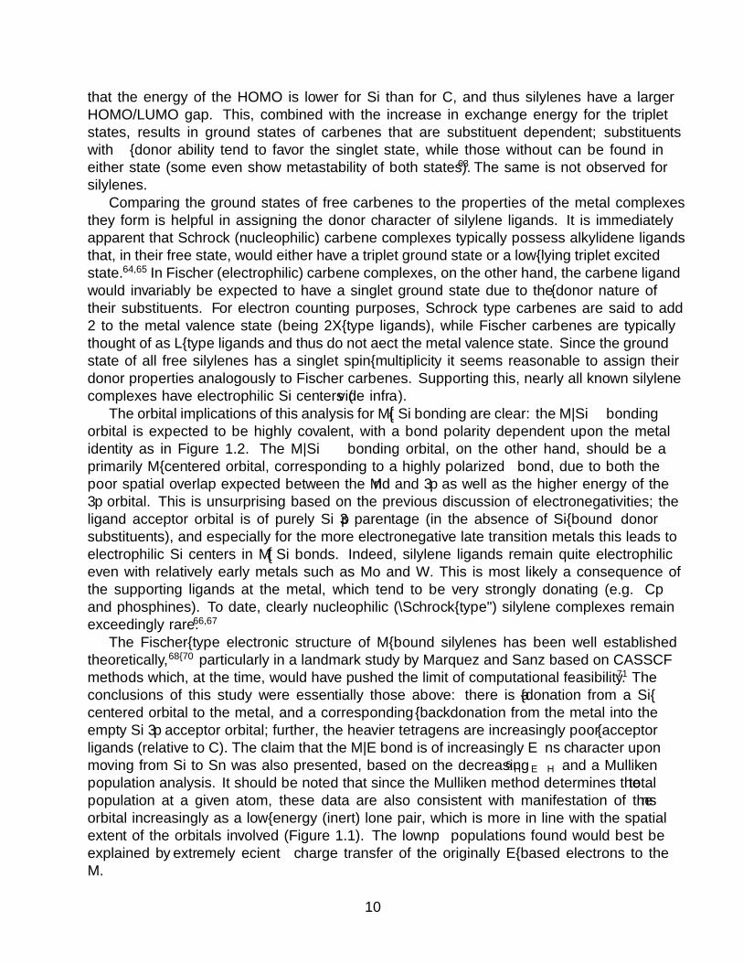
that the energy of the HOMO is lower for Si than for C, and thus silylenes have a largerHOMO/LUMO gap. This, combined with the increase in exchange energy for the tripletstates, results in ground states of carbenes that are substituent dependent; substituentswith π–donor ability tend to favor the singlet state, while those without can be found ineither state (some even show metastability of both states).63 The same is not observed forsilylenes.
Comparing the ground states of free carbenes to the properties of the metal complexesthey form is helpful in assigning the donor character of silylene ligands. It is immediatelyapparent that Schrock (nucleophilic) carbene complexes typically possess alkylidene ligandsthat, in their free state, would either have a triplet ground state or a low–lying triplet excitedstate.64,65 In Fischer (electrophilic) carbene complexes, on the other hand, the carbene ligandwould invariably be expected to have a singlet ground state due to the π–donor nature oftheir substituents. For electron counting purposes, Schrock type carbenes are said to add2 to the metal valence state (being 2X–type ligands), while Fischer carbenes are typicallythought of as L–type ligands and thus do not affect the metal valence state. Since the groundstate of all free silylenes has a singlet spin–multiplicity it seems reasonable to assign theirdonor properties analogously to Fischer carbenes. Supporting this, nearly all known silylenecomplexes have electrophilic Si centers (vide infra).
The orbital implications of this analysis for M––Si bonding are clear: the M—Si σ bondingorbital is expected to be highly covalent, with a bond polarity dependent upon the metalidentity as in Figure 1.2. The M—Si π bonding orbital, on the other hand, should be aprimarily M–centered orbital, corresponding to a highly polarized π bond, due to both thepoor spatial overlap expected between the M nd and 3p as well as the higher energy of the3p orbital. This is unsurprising based on the previous discussion of electronegativities; theligand acceptor orbital is of purely Si 3p parentage (in the absence of Si–bound π donorsubstituents), and especially for the more electronegative late transition metals this leads toelectrophilic Si centers in M––Si bonds. Indeed, silylene ligands remain quite electrophiliceven with relatively early metals such as Mo and W. This is most likely a consequence ofthe supporting ligands at the metal, which tend to be very strongly donating (e.g. Cp∗
and phosphines). To date, clearly nucleophilic (“Schrock–type”) silylene complexes remainexceedingly rare.66,67
The Fischer–type electronic structure of M–bound silylenes has been well establishedtheoretically,68–70 particularly in a landmark study by Marquez and Sanz based on CASSCFmethods which, at the time, would have pushed the limit of computational feasibility.71 Theconclusions of this study were essentially those above: there is a σ–donation from a Si–centered orbital to the metal, and a corresponding π–backdonation from the metal into theempty Si 3p acceptor orbital; further, the heavier tetragens are increasingly poor π–acceptorligands (relative to C). The claim that the M—E bond is of increasingly E ns character uponmoving from Si to Sn was also presented, based on the decreasing 6 H−E−H and a Mullikenpopulation analysis. It should be noted that since the Mulliken method determines the totalpopulation at a given atom, these data are also consistent with manifestation of the nsorbital increasingly as a low–energy (inert) lone pair, which is more in line with the spatialextent of the orbitals involved (Figure 1.1). The low npσ populations found would best beexplained by extremely efficient charge transfer of the originally E–based electrons to theM.
10

LnM- X-
LnM SiR3 LnM- X-
LnM SiR3XR3Si X SiR3
LnM R3Si X
+ +
+ LnMSiR3
XLnM SiR
3LnM R3Si HR +
- RX
a. b.
c. d.
Scheme 1.1: General synthetic schemes to access metal silyl complexes. a. Electrophilicfunctionalization of a metal center with a silyl halide. b. Nucleophilic functionalization ofa metal center with a silyl anion. c. Oxidative addition of a Si—X bond to a metal center;particularly common for X = H. d. Addition–elimination reaction between a metal alkyl oraryl and an Si—X fragment; particularly common for X = H. The same transformation isachieved by a σ–bond metathesis mechanism.
1.3 M—Si Single Bonds
Synthetic access to silyl complexes. As with the analogous alkyl complexes,synthetic routes to access metal silyl complexes can be broadly categorized into three classes:electrophilic, nucleophilic, and those involving bond activation (Scheme 1.1). Electrophilicsyntheses (Scheme 1.1a) generally involve treatment of an anionic metal complex with a silylhalide or a similar species. This method was used in the synthesis of the first transitionmetal silyl complex, wherein Na(Fp) (1.5) was treated with ClSiMe3 to give FpSiMe3 (1.6,eq 1.2).72 A major hurdle to this strategy is accessing the requisite anionic metal complexes.
Fe
OCOC
Fe
OCOC SiMe3
ClSiMe3
- NaCl
Na
PSfrag replacements
1.5 1.6
(1.2)
Nucleophilic silyl synthesis (Scheme 1.1b) involves reactions between a silyl anion anda metal complex, typically replacing a ligand such as a halide. While this is more generalfrom the perspective of the transition metal given the ubiquity of metal halide or pseudo-halide complexes, the inherent instability and difficulty in synthesis of all but a few silylanions reduces the scope of substituents on silicon.73,74 Thus, for silylation reactions nucle-ophilic functionalizations are less useful than the corresponding alkylation chemistry; wherethe ubiquity of alkyl lithium and Grignard reagents, as well as other readily available nu-cleophilic organometallic reagents, provides a plethora of conveniently available C–basednucleophiles. A number of nucleophilic silylation reagents are known, however, most notablyAk[Si(SiMe3)3] (Ak = alkali metal) and [Li ·THFn ]SiHMes2. The former is particularly note-worthy, as it has been used to access the Hf silyl, Cp2HfCl(Si(SiMe3)3) (1.7, eq 1.3),75 whichcan undergo exchange reactions with silanes to give other silyl derivatives (vide infra).
11

Hf
Si(SiMe3)3
ClHf
Cl
Cl [Li(THF)3][Si(SiMe3)3]
PSfrag replacements1.7
(1.3)
The final major class of silylation reactions involve activation of a Si—X bond by atransition metal fragment. This class can be further subdivided in three: pure oxidativeaddition reactions, addition–elimination reactions, and σ–bond metathesis. The first tworequire a coordinatively unsaturated metal center for which a valence increase by two wouldnot be onerous; for this reason they are particularly useful when starting with low–valentcomplexes. The purely oxidative addition scheme (Scheme 1.1c) results in a final productwith both the R3Si– and X– fragments as ligands, and an increase in the metal valenceby 2. These reactions have seen considerable application with hydrosilanes, reactions ofwhich are the most common method to introduce a silicon–containing ligand to a transitionmetal complex.76–78 Activation of the Si—H bond by metal centers is much more commonthan aliphatic C—H activation, likely due to the change in bond polarity and consequentfavorability for coordination of the Si—H bond prior to activation. In fact, for systems withboth an Si—H bond and another reactive moiety, e.g. a Si—Cl bond, activation of the Si—Hbond is often preferred.76–86
Addition–elimination mechanisms are also possible (Scheme 1.1d), involving the formalexchange of an alkyl or aryl ligand for a silyl ligand. This reaction is typically performed usinghydrosilanes, where trading the Si—H bond for a C—H bond drives the reaction. The majorutility of this transformation lies in the ubiquity of potential starting materials; unsaturatedand quasi–unsaturated* organometallic complexes are common across the d–block, and hy-drosilanes with various ancillary groups are readily available. Such addition–eliminationstrategies are thus very attractive as alternatives to the less–generalizable electrophilic andnucleophilic silylation reactions for introduction of only a silyl ligand (and not an oxida-tive addition partner ligand as well). When performed with primary and secondary silanes,there is the further possibility for α–H migration to form a silylene complex, which will bediscussed in detail in 1.5.
σ–bond metathesis reactions (Scheme 1.1d) to form silyl complexes are of particularutility at high–valent (i.e. d0) early metal centers, where the increase in metal valence by 2 isimpossible. This reaction was first used in the silyl exchange between 1.7 and PhSiH3, givingthe phenylsilyl complex Cp2HfCl(SiH2Ph) (1.8, eq 1.4).75 This transformation has beenexploited to some effect catalytically, in polymerization87 and hydrosilation.88 A potentialpitfall of this method is illustrated by the reaction between cationic Zr alkyl complexesand silanes, which can result in alkyl–H exchange rather than alkyl–silyl exchange.89 Whilemost σ–bond metatheses would involve transferring of H due to both bond polarity and the
*i.e. those that can lose a ligand to transiently become coordinatively unsaturated
12

E
HLnM
E
δ+ δ+
δ -
δ -
R'
HLnM
R
δ+ δ+
δ -
δ -
R3Si
HLnM
R
δ+
δ+
δ -
δ -
Figure 1.4: Polarization in a σ–bond metathesis transition state (top) and the interactionsbetween an alkane (bottom left) or silane (bottom right) and a metal alkyl.
more favorable electron density at H (over heavier atoms), partial negative charge on H insilanes makes the formation of a properly–polarized σ–bond metathesis transition state witha transferring hydride less favored (Figure 1.4).
Hf
Si(SiMe3)3
Cl PhSiH3
C6H6, ∆Hf
SiH2Ph
Cl
PSfrag replacements
1.7 1.8
(1.4)
It is possible to perform further nucleophilic chemistry at Si if a metal–bound silyl groupretains some easily–substituted functionality, e.g. a chloride ligand or another electronegativesubstituent. Typically, this would involve nucleophilic attack at Si by e.g. an organometallicreagent to introduce a new substituent at Si.90 One peculiar post–synthetic modification ofa silyl ligand involves the use of a metal silyl complex as a hydrosilation substrate (eq 1.5).In this case, the iron silyl Fp(SiHPh2) (1.9) was treated with phenylacetylene and catalyticchloroplatinic acid to give a mixture of the regioisomers, Fp(SiPh2)C(H)––CHPh (1.10a)and Fp(SiPh2)C(Ph)––CH2 (1.10b) .91
Fe
OCOC SiHPh2
cat. H2PtCl4
Fe
OCOC Si
Ph2
H
+R
R'
R = Ph, R' = HR = H, R' = Ph
PSfrag replacements
1.9 1.10a
1.10b
(1.5)
Reactivity of silyl complexes. The reactivity of the transition metal–silicon bondhas been well–treated in several review articles.55,76–78,92–94 A few salient features relevantto the discussions here should be be highlighted to provide a general understanding of their
13
reactivity patterns and to illustrate how the reactivity of silyl complexes reflects the bondingin these molecules.
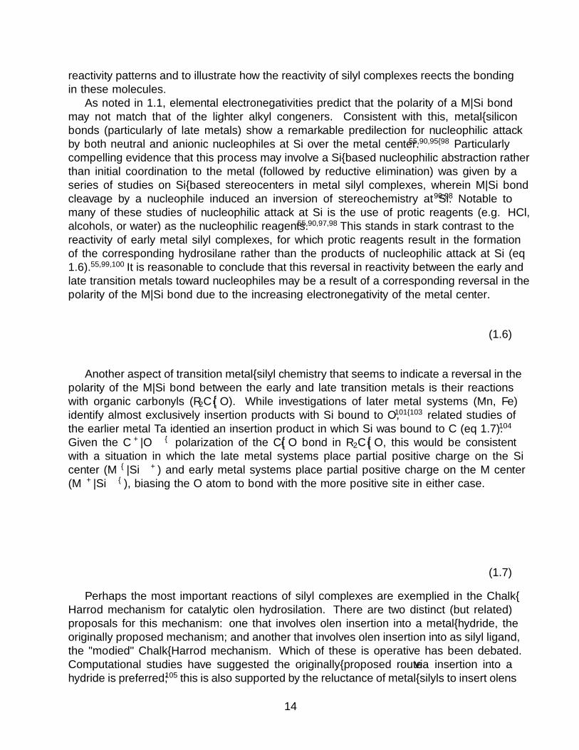
As noted in 1.1, elemental electronegativities predict that the polarity of a M—Si bondmay not match that of the lighter alkyl congeners. Consistent with this, metal–siliconbonds (particularly of late metals) show a remarkable predilection for nucleophilic attackby both neutral and anionic nucleophiles at Si over the metal center.55,90,95–98 Particularlycompelling evidence that this process may involve a Si–based nucleophilic abstraction ratherthan initial coordination to the metal (followed by reductive elimination) was given by aseries of studies on Si–based stereocenters in metal silyl complexes, wherein M—Si bondcleavage by a nucleophile induced an inversion of stereochemistry at Si.90,98 Notable tomany of these studies of nucleophilic attack at Si is the use of protic reagents (e.g. HCl,alcohols, or water) as the nucleophilic reagents.55,90,97,98 This stands in stark contrast to thereactivity of early metal silyl complexes, for which protic reagents result in the formationof the corresponding hydrosilane rather than the products of nucleophilic attack at Si (eq1.6).55,99,100 It is reasonable to conclude that this reversal in reactivity between the early andlate transition metals toward nucleophiles may be a result of a corresponding reversal in thepolarity of the M—Si bond due to the increasing electronegativity of the metal center.
SiR3LnMHX
SiR3H SiR3X or
M = Early TM M = Late TM(1.6)
Another aspect of transition metal–silyl chemistry that seems to indicate a reversal in thepolarity of the M—Si bond between the early and late transition metals is their reactionswith organic carbonyls (R2C––O). While investigations of later metal systems (Mn, Fe)identify almost exclusively insertion products with Si bound to O,101–103 related studies ofthe earlier metal Ta identified an insertion product in which Si was bound to C (eq 1.7).104
Given the Cδ+—Oδ – polarization of the C––O bond in R2C––O, this would be consistentwith a situation in which the late metal systems place partial positive charge on the Sicenter (Mδ – —Siδ+) and early metal systems place partial positive charge on the M center(Mδ+—Siδ – ), biasing the O atom to bond with the more positive site in either case.
SiR3LnMR2C
or
M = Ta M = Fe, Mn
LnMO
CR2
SiR3LnM
R2C
OSiR3O
(1.7)
Perhaps the most important reactions of silyl complexes are exemplified in the Chalk–Harrod mechanism for catalytic olefin hydrosilation. There are two distinct (but related)proposals for this mechanism: one that involves olefin insertion into a metal–hydride, theoriginally proposed mechanism; and another that involves olefin insertion into as silyl ligand,the ”modified” Chalk–Harrod mechanism. Which of these is operative has been debated.Computational studies have suggested the originally–proposed route via insertion into ahydride is preferred;105 this is also supported by the reluctance of metal–silyls to insert olefins
14

(relative to alkyls)55 and the high rates of insertion/elimination into metal hydrides. Themajor observation cited in favor of the modified Chalk–Harrod mechanism is the detection ofvinylsilanes as minor products of catalysis;55,105 however, given that the modified mechanismis computed to be extremely energetically disfavored,105 their formation via another, off–cyclemechanism seems more likely.
A distinct disadvantage of the Chalk–Harrod mechanism is the reliance on a reversiblemigratory insertion into a M—H bond. While these will typically result in the formationof a linear* metal alkyl complex (which then forms linear silanes via reductive elimination)there is the possibility for the formation of the branched alkyl isomer, leading to branchedsilane products. Improving the selectivity for the more desired linear isomeric product is oneof several important goals in hydrosilation catalysis research.
The assertion that metal silyl complexes are less prone to insert olefinic substrates thantheir carbon congeners warrants further discussion. It has been suggested that this is dueto π–bonding effects between the metal and the silyl ligand, which hinders insertion of anolefin into the metal–Si bond.55 However, the more recent proposal that M—Si bondingcontains only trace π contributions59 indicates that perhaps another factor dominates thisreluctance to engage in insertion chemistry. Since the metal center is more electron richin silyl complexes than alkyl complexes, another reasonable explanation is that the olefinin metal–silyl complexes is less prone to insert by virtue of stronger backdonation into theC—C π∗ orbital. This has a parallel in olefin polymerization chemistry catalyzed by groupIV metal complexes, wherein the d0 catalysts react more quickly than d1 catalysts which canbackdonate into the olefin substrate.
1.4 Metal–Silicon Multiple Bonds: Silylene omplexes
Historical development of M––Si chemistry. Silylene complexes have been pro-posed as transient intermediates in catalytic and stoichiometric transformations for nearly50 years.8–11,13,14,17,106,107 The first report of a base–stabilized silylene complex was in 1977by Schmid and Welz of thermally unstable (CO)4FeSiMe2(NMe2H)15 was quickly followedby a report from Sakurai et al of a compound formulated as (CO)4(SiMe3)(H)Fe––SiMe2.18
The minimal characterization of these molecules, and notably the lack of structural charac-terization, has led to descriptions such as “almost hypothetical”,68 and likely explains thenear–disappearance of particularly the latter from citations after ca. 1990.
A decade passed before the full structural characterization of base–stabilized silylenecomplexes in the late 1980s,16,69,108 after which attention naturally turned to developmentof base–free silylene complexes. Mounting evidence for the lability of the stabilizing base109
confirmed the viability of silylene complexes as transient intermediates, and implied thecomplexes should be sufficiently stable to allow for isolation. The isolation of a base–freeheteroatom–substituted metal silylene complex, [Cp∗(PMe3)2Ru––Si(SpTol)2][BPh4] (1.11)soon followed.110 This complex was accessed by triflate abstraction from the silyl precur-
*In the hydrosilation literature this is often termed the “anti–Markovnikov” product for historical reasons.This is correct if Markovnikov’s rule is interpreted with silanes as “HX” reagents; however, the electronicorigin of Markovnikov’s rule, namely that the more electropositive element will prefer the terminal site ofan olefin, would lead to a prediction of linear selectivity in hydrosilation reactions. Thus, here the terms“linear” and “branched” are preferred.
15

sor, Cp∗(PMe3)2RuSi(SpTol)2(OTf) (1.12), with NaBPh4 in methylene chloride (eq 1.8).It was postulated that π–donation to the electrophilic silicon center by the thiopheno-late substituents contributed to the stability of the complex.110 Base–free silylene com-plexes without heteroatom substitution were first reported in 1994. The initial crystallo-graphically characterized example of this class of compounds, [Cp∗(PMe3)2Ru––SiMe2][BArF
4 ](1.13), was synthesized analogously to 1.11,111 via bstraction of the Si–bound triflate inCp∗(PMe3)2RuSiMe2(OTf) (1.14) by LiBArF
4 ·OEt2 (eq 1.8).
RuMe3P
Me3PSi
R
OTf
R
R = SpTolR = Me
RuMe3P
Me3PSi
R
R[Ak][BAr4]
−AkOTf
Ak = Na, Ar = PhAk = Li, Ar = C6F5
PSfrag replacements
1.12
1.14
1.11
1.13
(1.8)
The next major advance was the discovery of α–H migration processes that give rise tosilylene hydride complexes. The first definitive evidence for this process was reported for(dippe)Pt(SiHMes2)Me (1.15), where upon methyl abstraction by B(C6F5)3 the Si–boundH migrates to Pt to form (dippe)Pt(H)––SiMes2 (1.16, eq 1.9).112 This was particularlyimportant in the context of speculation about the intermediacy of silylene complexes incatalytic transformations, wherein α–H migrations were proposed as a major pathway bywhich silylene complex intermediates would form in a catalytic reaction.
B(C6F5)3
Pt
MeP
P HSi
Mes
Mes
iPr iPr
iPr iPr
Pt
HP
P Si
Mes
Mes
iPr iPr
iPr iPrPSfrag replacements
1.15 1.16
(1.9)
The recognition of this α–H migration as a viable path to metal–bound silylenes hasled to broad applications in the synthesis of and catalytic transformations involving silylenecomplexes. The use of α–H migration as a viable route to silylene complexes directly fromsilanes was first reported in 1999, for the reaction of (BP3
Ph)Ir(H)(η3−C8H15) (1.17) withsecondary silanes. In this case, initial addition of silane is proceeded by COE elimination and
16
α–H migration to give the crystallographically characterized (BP3Ph)(H)2Ir ––SiMes2 (1.18,
eq 1.10).113
B(C6F5)3
Ir
PPh2
Ph2PPh2P
H
B
Ph
Ir
PPh2
Ph2PPh2P
H
B
Ph
HSi
Mes
Mes−C8H16
PSfrag replacements
1.17 1.18
(1.10)
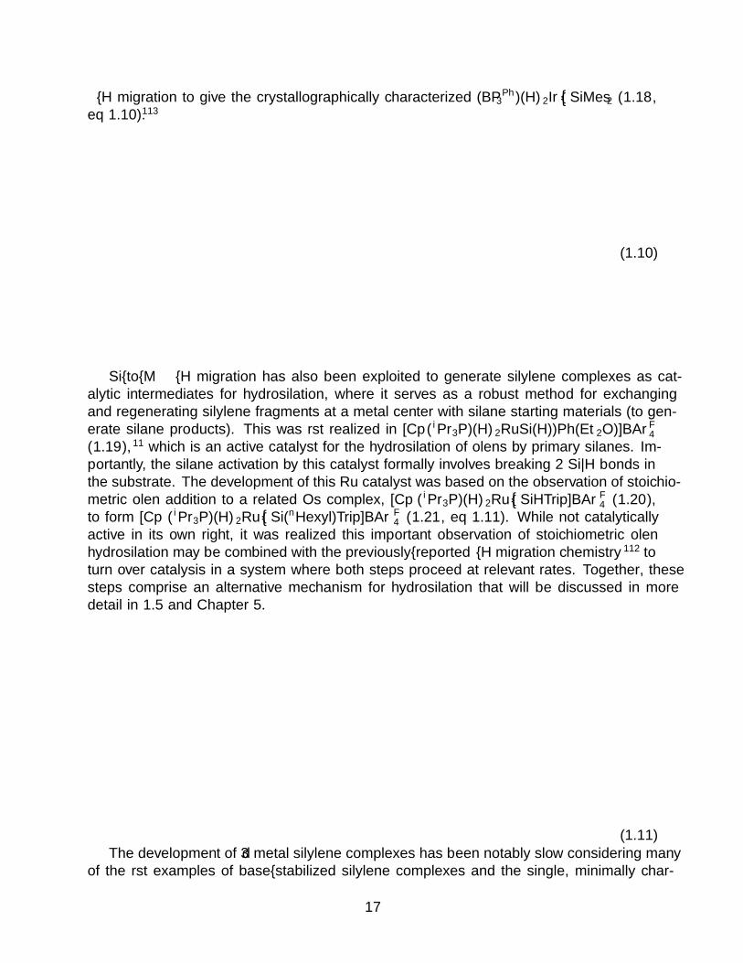
Si–to–M α–H migration has also been exploited to generate silylene complexes as cat-alytic intermediates for hydrosilation, where it serves as a robust method for exchangingand regenerating silylene fragments at a metal center with silane starting materials (to gen-erate silane products). This was first realized in [Cp∗(iPr3P)(H)2RuSi(H))Ph(Et2O)]BArF
4
(1.19),11 which is an active catalyst for the hydrosilation of olefins by primary silanes. Im-portantly, the silane activation by this catalyst formally involves breaking 2 Si—H bonds inthe substrate. The development of this Ru catalyst was based on the observation of stoichio-metric olefin addition to a related Os complex, [Cp∗(iPr3P)(H)2Ru––SiHTrip]BArF
4 (1.20),to form [Cp∗(iPr3P)(H)2Ru––Si(nHexyl)Trip]BArF
4 (1.21, eq 1.11). While not catalyticallyactive in its own right, it was realized this important observation of stoichiometric olefinhydrosilation may be combined with the previously–reported α–H migration chemistry112 toturn over catalysis in a system where both steps proceed at relevant rates. Together, thesesteps comprise an alternative mechanism for hydrosilation that will be discussed in moredetail in 1.5 and Chapter 5.
Os
P SiH H
H
C4H9Os
P SiH H
C4H9
Trip Trip
PSfrag replacements
1.20 1.21
(1.11)The development of 3d metal silylene complexes has been notably slow considering many
of the first examples of base–stabilized silylene complexes and the single, minimally char-
17

acterized base–free complex reported in 1978 were all based on Fe.15–18 The first struc-turally characterized example of an iron silylene complex, Cp∗(CO)(SiMe3)Fe––SiMes2 (1.4),was reported in 2003.19 The synthesis was by photolysis of Fp∗Me with Mes2MeSiSiMe2Hand apparently proceeds by addition–elimination to photolytically generated Cp∗(CO)FeMeto form Cp∗(CO)FeSiMe2(SiMeMes2), followed by a series of silyl– and alkyl–migrationsto form the final product. This has been followed by only a handful of examples of 3dcomplexes with unsaturated metal–silicon interactions of any type; these are limited toBPiPr
3 (H)Fe(η3−H2SiHPh) (1.22),114 [(dtbpe)Ni(µ–H)SiMes2]+ (1.23),115 Cp2(THF)Ti––Si-(Si3(SiR3)4) (1.24),67* trans- and cis-(dmpe)(H)Mn––SiR2 (trans-, 1.25a; cis-, 1.25b) (R =Et, Ph),116 the Cp∗(iPr2MeP )(H)FeSiRH complexes discussed in Chapter 4,117 and [Cp∗-(iPr2MeP)Fe(η3−H2SiRH]+ discussed in Chapter 5. The common theme to all these com-plexes (except the Ti example with a nucleophilic silylene center) is the extreme degree ofelectrophilicity imparted at Si by coordination to a 3d metal center. As a result, most ofthese complexes feature either ground states or equilibrium processes wherein interactionwith another ligand, such as a M–bound or bridging H, lends some electron density to Si ineither a bridging interaction114–116 or through migration chemistry.19,117
SiR3Ti
Os
OC SiMe3Si Fe
PiPr2
PP
H
B
Ph
iPr2
iPr2
HH
Si
Me
Ph
Mes
Mes
Ni
HP
P
SiMes
Mes
tBu tBu
tBu tBu
SiSi
Si
Si(SiR3)2
SiR3
Mn
Me2P
PMe2
Me2P
PMe2
SiR2
H
Mn
Me2P
PMe2
PMe2
Me2P
R2Si
HPSfrag replacements
1.4 1.22 1.23
1.24 1.25a 1.25b
Figure 1.5: Structurally characterized examples of 3d metal complexes with unsaturatedM—Si interactions.
Access to M––Si complexes. Syntheses of silylene complexes have been realized bythree major routes. Particularly for the earliest–reported silylene complexes, their syntheseswere largely achieved by abstraction of a Si substituent in a metal silyl to form the silylene
*The silylene ligand in this complex is bicyclic and derived from tetrasilabicyclo[1.1.0]butane–2,4–diide;R3Si = SiMetBu2
18

LnM- X-
LnM SiR2 LnMSiR2X SiR2
LnM R2SiH2
+
+ LnM R +- RH
a. b.
c. d.
LnM SiR2
LnM SiR2
H
H
R2SiH2 LnM SiR2
H
Figure 1.6: General synthetic methods to form silylene complexes. a. Abstraction of asubstituent from a metal–bound silyl ligand.b. Coordination of a free silylene to a metalcenter. Two variations of silylene extrusion: c. to form a silylene dihydride complex, andd. addition–elimination reaction with a metal alkyl complex, followed by α–H migration toform a silylene hydride complex.
complex (Figure 1.6a). The utility of this strategy is immediately apparent; it is possibleto form a silyl complex with a suitable leaving group using all of the silylation reactionsdiscussed in 1.3. Variety in the abstracted group is large, and includes halides, pseudohalidessuch as triflate, and hydrides.2,3
A less well–established route involves coordination of a free silylene to a vacant site on ametal center (Figure 1.6b).* Its utility is primarily limited by the availability of free silylenes,of which the N–heterocyclic silylenes are the best developed. This route is markedly lesscommon for silylenes with hydrocarbyl substituents, which have the tendency to dimerizeand form disilenes (and are thus synthetically more challenging to employ); however, it hasbeen used to some success in the reaction between (PR3)2Pt (R = Cy, 1.26; R = iPr, 1.27)and SiMes2 (eq 1.12), which affords the corresponding (PR3)2Pt––SiMes2 (R = Cy, 1.28; R= iPr, 1.29) complexes.
hν(PR3)2Pt + Mes2Si(SiMe3)2 Pt
R3P
R3P
Si
Mes
Mes
R = CyR = iPr
PSfrag replacements
1.26
1.27
1.28
1.29
(1.12)
A final method for the preparation of silylene complexes is so–called “silylene extrusion”,wherein a primary or secondary silane is converted by a single synthetic manipulation into ametal–bound silylene (Figure 1.6c). This method involves activation of two Si—H bonds toform the final silylene product, for the formal “extrusion” of a M–bound SiR2. In many cases,this process is stepwise and proceeds via oxidative addition followed by an α–H migration,and following the oxidative addition step the newly metal–bound hydride ligand is removedvia reductive elimination with a hydrocarbyl ligand from the starting metal complex (Fig-ure 1.6d). Variations on this route have been utilized extensively for the synthesis of mixed
*This strategy is much more common for the heavier congeners of Si, particularly Sn.
19

hydride–silylene complexes; notable examples include 1.18,113 Cp∗(R3P)(H)M––SiRR′ (M =Os,20 Ru,21 Fe, 4117), (dmpe)2(H)Mn––SiR2,116 CpEtMe4(CO)(H)W––Si(H)TSi),118
Reactivity of M––Si bonds. The simplest, and perhaps most common, reactionof silylene complexes is association of another substituent to the silylene center; this isthe microscopic reverse of abstraction of a substituent at Si (which has been used for thesynthesis of silylene complexes).2,3 Ligand association and dissociation has been observedextensively in base–stabilized silylene complexes, many of which are thought to undergoreversible dissociation of their stabilizing base and are formed by coordination of a base toa free silylene center.11,109,119 Additionally, any reaction in which the Si center acts as anelectrophile will likely involve at least an initial coordination of substrate to Si, making thiselementary step important to understanding more complicated reactions.
This process proceeds by coordination of ligand (L) to the largely Si 3p π∗ orbital of theparent silylene complex. As the L—Si bond forms, the M––Si π bond is broken and planarityat Si is disrupted; as such, with increasingly donating L at Si, the group gains more “silyl”character.3 It has been proposed that, at least for weakly–coordinating L, some degree ofresidual M––Si π bonding remains between the M dπ and the Si–Lσ∗ . Note that this hasalso been proposed as the reason for bond shortening in silyl groups56,57 where it was foundthat M—Si π bonding is negligible;59 however, for at least the base–stabilized silylene com-plexes with weakly–bound L the much lower energy of the Si–Lσ∗ orbital makes such aninteraction more feasible. It remains possible, though, that while M—Si bond distances inbase–stabilized silylene complexes are typically shorter than similar M—Si silyl distances,the (formal) positive charge on the Si ligand leads to an increase in the bond–shorteningelectrostatic interactions attributed to silyl ligands.59 The reaction between silylene com-plexes and water or alcohols represents a special case of nucleophilic attack at Si. Whilemany such reactions result in the complete cleavage of the M––Si bond to form disiloxanesor alkoxysilanes, in some cases this reaction results in the formation of a silyl hydrdidecomplex,* reminiscent of an O—H addition across the M––Si bond.1
Another important class of reactivity for silylene complexes involves migration of a hy-dride, silyl, or hydrocarbyl group, sometimes termed a sigmatropic rearrangement if themigration is between a silylene and silyl ligand rather than a silyl ligand and the metalcenter. This is a particularly important reaction class, as either 1,2– or 1,3–migrationchemistry is the process by which silylene complexes are thought to form as catalytic in-termediates.11,13,69,73,106,112,120–128� Migration chemistry apparently involving silyl and alkylsubstituents in M–bound silyl ligands was first observed in 1970 in the disproportionationof R3Si–SiR2 –X to R3Si– (SiR2)n –X catalyzed by (Et3P)2PtCl2. A possible mechanismfor these disproportionation reaction proceeds via intermediate mixed silyl/silylene metalcomplexes, which have been investigated extensively by Tobita and Ogino and, separately,Pannell and coworkers. These investigations have led to the conclusion that 1,2– and 1,3–migratory rearrangements in silyl and mixed silyl/silylene complexes, respectively, are acces-sible at room temperature and the transient generation of silylene complexes, when possible,is a reasonable route by which catalysis may proceed.
*More generally, for the reaction between Ln(H)nM––SiR2 and R′OH the product is Ln(H)n+1MSiR2(OR′�A more detailed discussion of the M—Si α–H migration will be reserved for 1.5, as H–migrations there
exists a continuum along which there is a substantial amount of ambiguity in what constitutes an α–agosticinteractions vs. α–H migrations
20
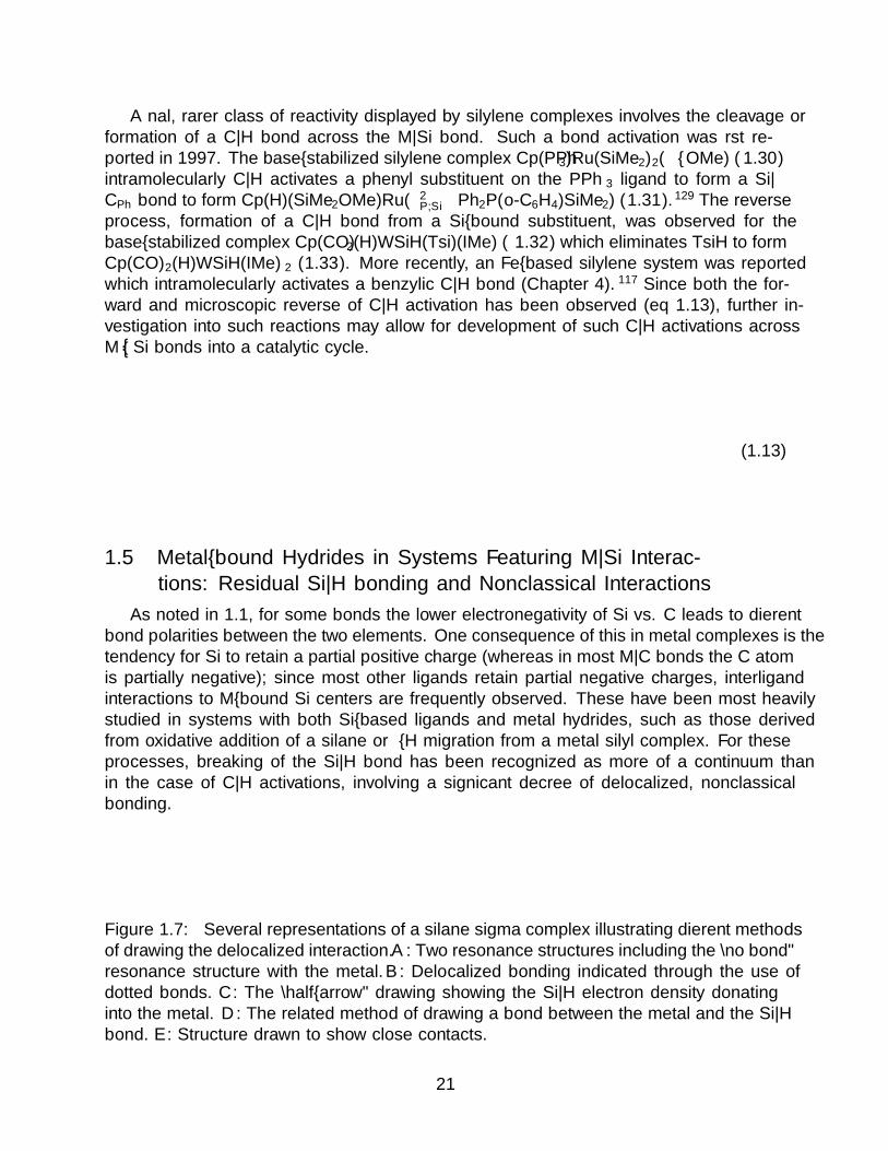
A final, rarer class of reactivity displayed by silylene complexes involves the cleavage orformation of a C—H bond across the M—Si bond. Such a bond activation was first re-ported in 1997. The base–stabilized silylene complex Cp(PPh3)Ru(SiMe2)2(µ–OMe) (1.30)intramolecularly C—H activates a phenyl substituent on the PPh3 ligand to form a Si—CPh bond to form Cp(H)(SiMe2OMe)Ru(κ2
P,Si−Ph2P(o-C6H4)SiMe2) (1.31).129 The reverseprocess, formation of a C—H bond from a Si–bound substituent, was observed for thebase–stabilized complex Cp(CO)2(H)WSiH(Tsi)(IMe) (1.32) which eliminates TsiH to formCp(CO)2(H)WSiH(IMe)2 (1.33). More recently, an Fe–based silylene system was reportedwhich intramolecularly activates a benzylic C—H bond (Chapter 4).117 Since both the for-ward and microscopic reverse of C—H activation has been observed (eq 1.13), further in-vestigation into such reactions may allow for development of such C—H activations acrossM––Si bonds into a catalytic cycle.
LnM SiR
RLnM Si
R
R
R'
+ R'H
M = Fe, Ru
− R'H
M = W
H
(1.13)
1.5 Metal–bound Hydrides in Systems Featuring M—Si Interac-tions: Residual Si—H bonding and Nonclassical Interactions
As noted in 1.1, for some bonds the lower electronegativity of Si vs. C leads to differentbond polarities between the two elements. One consequence of this in metal complexes is thetendency for Si to retain a partial positive charge (whereas in most M—C bonds the C atomis partially negative); since most other ligands retain partial negative charges, interligandinteractions to M–bound Si centers are frequently observed. These have been most heavilystudied in systems with both Si–based ligands and metal hydrides, such as those derivedfrom oxidative addition of a silane or α–H migration from a metal silyl complex. For theseprocesses, breaking of the Si—H bond has been recognized as more of a continuum thanin the case of C—H activations, involving a significant decree of delocalized, nonclassicalbonding.
LnM
H
SiR3LnM
H
SiR3
LnM
H
SiR3
LnM
H
SiR3
LnM
H
SiR3
LnM
H
SiR3
A B C D E
Figure 1.7: Several representations of a silane sigma complex illustrating different methodsof drawing the delocalized interaction. A: Two resonance structures including the “no bond”resonance structure with the metal. B: Delocalized bonding indicated through the use ofdotted bonds. C: The “half–arrow” drawing showing the Si—H electron density donatinginto the metal. D: The related method of drawing a bond between the metal and the Si—Hbond. E: Structure drawn to show close contacts.
21

It should be noted that in chemical drawings of systems with both M–bound Si and H,a bewildering variety of representations are often used to convey similar structural motifs(Figure 1.7). Common choices include the use of resonance structures in a way familiar tovalence bond theory (A); the use of dashed bonds to indicate delocalization or weakenedbonding (B); the so–called “half–arrow” notation (and the related use of a bond to a bond)(C, D); and using a full line to indicate any interaction, regardless of strength (E). Whileeach representation has its advantages, it is perhaps most important to be consistent in orderto avoid confusion. Therefore, solid lines will be used here to indicate bonds, with dashedlines used to show highly delocalized or weakened interactions (i.e. method B in Figure 1.7).
Characterization of residual Si—H interactions. Characterization of the highlydelocalized, nonclassical bonding in complexes with both silicon–based and hydride ligandsis challenging; nonetheless, there are several experimental and theoretical techniques whichhave provided insight into the bonding structure of these molecules. The most conclu-sive investigations of residual Si—H interactions have involved a hybrid of high–qualitystructural data with computational investigations. For these studies, experimental electrondensity maps are compared to those from e.g. DFT computations to characterize bondingusing QTAIM or similar density analyses.83,84,86,130,131 These studies have provided partic-ularly valuable insight into the process by which oxidative addition takes place in thesesystems, and led to a unified understanding of the bonding in silane σ–complexes.86 Neutrondiffraction has also been used to extract accurate hydride positions in silane and silylenecomplexes;80,83,85,132,133 however the scarcity of neutron sources has limited the broad appli-cation of this technique. With ready access to modern computational resources, techniquessuch as Hirshfeld atom refinement may allow for more routine determination of accuratehydride positions by refinement of X–ray data against quantum chemical calculations ofelectron density,134,135 obviating the need for neutron diffraction data in many cases.
Rapid characterization of residual Si—H bonding has largely been achieved through theinterpretation of NMR spectroscopic parameters, most notably J SiH but also δH and δSi. δH
is the easiest to interpret, as binding of a hydrogen to a metal center induces a characteristicupfield shift.136 The interpretation of J SiH is much more complicated. For the oxidativeaddition continuum (vide infra) a line has traditionally been drawn at 20 Hz to distinguishbetween oxidative addition and σ–complexes of silanes, with lower magnitudes (3–10 Hz)assigned to full oxidative addition products and higher magnitudes (20–100 Hz) thoughtto be more in line with 1J SiH in silanes (which are typically around −200 Hz).76–78,86,131,136
More recently this delimiter was called into question, however, based on the observationthat for some systems coupling constants seem to increase along the oxidative additioncontinuum.79,136–141
A more nuanced treatment of the coupling constant effects in these systems requires therecognition of two basic features of the observed coupling, Jobs. These are that the couplingdepends on both the one– and two–bond effects (the latter a through–M effect) (eq 1.14); andthat while one–bond coupling is typically negative, two–bond coupling is frequently positive.Notably, it is expected that as the Si—H bond is ruptured, 1JSiH will decrease at the sametime as 2JSiH increases, leading to an initial, rapid increase in Jobs (from −200); at somepoint, 2JSiH will dominate and Jobs will pass through 0.131 Since most NMR experimentsdo not distinguish negative from positive coupling constants, they are typically reported as∣∣Jobs∣∣ which further complicates the analysis.
22

Jobs =1 JSiH +2 JSiH (1.14)
More recently, the Fermi contact (FC) contributions to the coupling constants alongthe oxidative addition continuum for Si—H bonds have been explicitly rationalized from amolecular orbital perspective informed by the extended Dewar–Chatt–Duncanson treatment(vide infra). This was accomplished by treating the coupling in terms of the contributions ofπ/σ∗ and σ/σ∗ pair of orbitals described by eq 1.15,* which relates the energies and orbitalcoefficients of an occupied/virtual pair to their coupling contributions. It was noted that forσ effects the coupling is negative due to the constructive Si—H overlap, while for π effects apositive coupling results due to the destructive Si—H overlap in the M—SiH π–backbondingorbital (which originates from Si—H σ∗). The conclusions of this treatment are largely thesame as invoking eq 1.14, namely that as M—H and M—Si bond character increases (andSi—H character decreases) Jobs should increase (and pass through zero); however, explicitlystating the origin of this effect from a molecular orbital standpoint is valuable for generalizingthe treatment to other bonding situations. Investigations into the J coupling along the α–H migration and η3–silane continua would be invaluable to the understanding of electronicstructure in these systems.
Jπ/σ(SiH) ∝ −co(Si)cv(Si)co(H)cv(H)
εo − εv(1.15)
In addition to NMR spectroscopy, vibrational spectroscopy (IR, Raman) holds greatpotential to probe the strength of interactions between Si and M—H ligands. Both terminalSi—H and M—H stretching modes typically have energies in the 1900–2200 cm–1 range,making them relatively facile to assign due to the scarcity of other modes with this energyin most molecules. These bands have a tendency to broaden and move to lower energy uponforming bridging interactions; already with silane σ–complexes the Si—H band is oftenredshifted to between 1600-1800 cm–1;76–78 thus, particularly for intermediate cases (suchas ASOAP/SOAP, arrested α–H migrations, or η3–silane complexes, vide infra) these bandscan redshift into the heavily populated region below 1600 cm–1 and can thus be difficult toidentify without isotopic labeling
LnM
H
SiR3
increasing silane activation
LnM
H
SiR3
free silane σ complex
LnM
H
Si
SOAP or IHI
LnM
H
SiR3
full oxidative addition
LnM
H
SiR3
ASOAP
Figure 1.8: Schematic representation of the continuum of activation of a Si—H bond by ametal center. Solid vs. dashed bonds show the relative strength of bonds at a given level ofactivation.
*The full treatment of this analysis is well–outlined in an excellent J. Chem. Ed. paper by Autschbach142
23

The oxidative addition continuum. The activation of E—H bonds (E = C, Si) byoxidative addition at a metal center likely proceeds via an intermediate E—H σ–complex,wherein electron density from an E—H bond is donated to the metal center in a three–center two–electron (3c–2e) bonding interaction (Figure 1.8). While in C—H activations thedifference between these σ–complexes and fully oxidatively added products is often clear, forSi this process is recognized as a continuum along which there exist intermediate cases withpartially–activated Si—H bonds and/or strong interligand interactions between silyl groupsand M–bound hydrides. These intermediate cases have been reviewed extensively, but thesalient features will be addressed here.
LnM
H
Si
δ -
δ+ LnM
H
C
δ -
δ -
Figure 1.9: Drawing of aninterligand interaction be-tween a silyl and hydrideshowing the electrostatic fa-vorability of such an inter-action for a silyl vs. alkyl
Along the oxidative addition continuum, an orbital struc-ture similar to the Dewar–Chatt–Duncanson type activation ofan olefin develops;84,131,136 the initial orbital structure involvedat Si is clearly a σ/σ∗ pair while at the metal center theremust be a sigma acceptor orbital as well as a pair of electronswith which to form bonds to the oxidatively added silane. In-creasingly ruptured Si—H bonds corresponding to a buildupof donation into the σ∗ orbital of the silane, with concomitantbuildup of M—H and M—Si σ bond character, leading finallyto the formation of a cis–hydride/silyl complex wherein the Hand Si are σ–bonded to the metal sharing the same nd orbital.This is exactly the orbital structure encountered in C—H bond
activations; however, residual Si—H bonding character is retained much later in the process,due primarily to bond polarity differences – i.e. buildup of negative charge at Si occursmuch later (if at all) compared to C, leading to less repulsion between the oxidatively addedligands that would tend to disfavor any interaction between them (Figure 1.9).
Silane σ–complexes featuring partially–activated Si–H bonds are well–documented withsilane coordinating to the metal center in either an η1– or η2–fashion.76–78,86 Further along thesilane activation continuum there are cases where the Si—H bond has been largely ruptured.At this point there are two distinct structural motifs that have been identified,76–78,84,131 bothinvolving strong metal–H interactions but varying in their degree of interaction between themetal and Si; these have been termed asymmetric oxidative addition product (ASOAP,for the case with strong bonding to only H) and symmetric oxidative addition product(SOAP, for the case of strong bonding to both Si and H). In the latter there are manycases with residual bonding character between the silyl and H ligands not typically observedfor oxidatively added hydrocarbons, distinguishing them from the full oxidative additionproduct defining the end of the oxidative addition continuum.
One aspect of these interactions that often manifests structurally is the tendency of theSi to adopt a geometry in which an electronegative substituent (e.g. Cl) at Si is trans–to the M–bound hydride ligand; electronically these have been interpreted as originatingfrom donation of the M—H bonding electrons into the Si—Xtrans σ
∗ orbital, and are pro-posed to strengthen with increasing electronegativity of X. These residual bonds have beentermed “interligand hypervalent interactions” (IHI) by Nikonov and coworkers, highlight-ing the similarity to other, non–metal–bound hypercoordinate silicon compounds.80,82,136,143
More recent interpretations based on QTAIM call this into question, however, and proposethat there are no features which distinguish IHI from the broader continuum of electronic
24

structures, and that the influence of electronegative substituents on Si is simply to changethe bonding properties between the M and Si rather than Si and H.83,84,130
LnM
increasing silane activation
free silane α agostic interaction arrested α migration full α migration
SiR2
H
LnM SiR2
H
LnM SiR2
H
LnM SiR2
H
Figure 1.10: Schematic representation of the continuum of α–migration of a Si—H bondto a metal center. Solid vs. dashed bonds show the relative strength of bonds and buildupof double–bond character along the α–migration coordinate.
H+
M SiR
R
M SiR
R
M SiR
RH
M SiR
RH
M SiR
RH
M SiR2
π
π∗
1s
Figure 1.11: MO diagram showingthe interaction between the 1s or-bital on a proton bridging betweena metal and Si center in a silylenecomplex. Red: The parent M––Si πorbital. Green: The parent M––Siπ∗ orbital. Blue: The H 1s orbital.Adapted from Iluc and Hilhouse.115
M—Si α–H migration. A similar continuumto oxidative addition of Si—H bonds exists for α–H migration processes from silyl ligands, which havebeen observed as terminal silyls, α–agostic interac-tions, bridged structures (sometimes termed an “ar-rested” α migration), and finally the fully–migratedsilylene hydride structure (Figure 1.10). Structurally,these differ from the oxidative addition continuum byvirtue of the already–formed M—Si σ–bonding or-bital; along the continuum instead there is a buildupof M––Si π bonding (as well as M—H bonding).
Distinct orbital structures are encountered at boththe beginning and end of this continuum. The parenthydrosilyl complex is purely σ–bound with the metalcenter, which should necessarily posses an empty ndorbital into which the α–H migration will take place.This orbital will also form the metal componenet ofthe M—Si π bond in the fully migrated complex.Along the α–migration coordinate the Si planarizes,and a nearly pure 3p π orbital manifests at Si as M—Hbonding builds. This leads to the intermediate elec-tronic structure, of which Iluc and Hilhouse presenteda valuable analysis for [(dtbpe)Ni(µ–H)SiMes2]+.115
Their treatment involved perturbation of the parentsilylene electronic structure of (diphos)Ni––SiR2 by addition of a proton to the M––Si bond,forming a bridging interaction (Figure 1.11). This sets up a three–orbital manifold in whichthe M—Si π HOMO has split into an occupied/virtual pair by virtue of mixing with thehydrogen 1s orbital, with the M—Si π∗ maintained as the LUMO. Finally, with full α–H mi-gration (to a cis– arrangement) the M—H bond is fully orthogonal to the M––Si π manifold,and forms by interaction with the M orbital responsible for σ bonding to the silylene ligand.
25
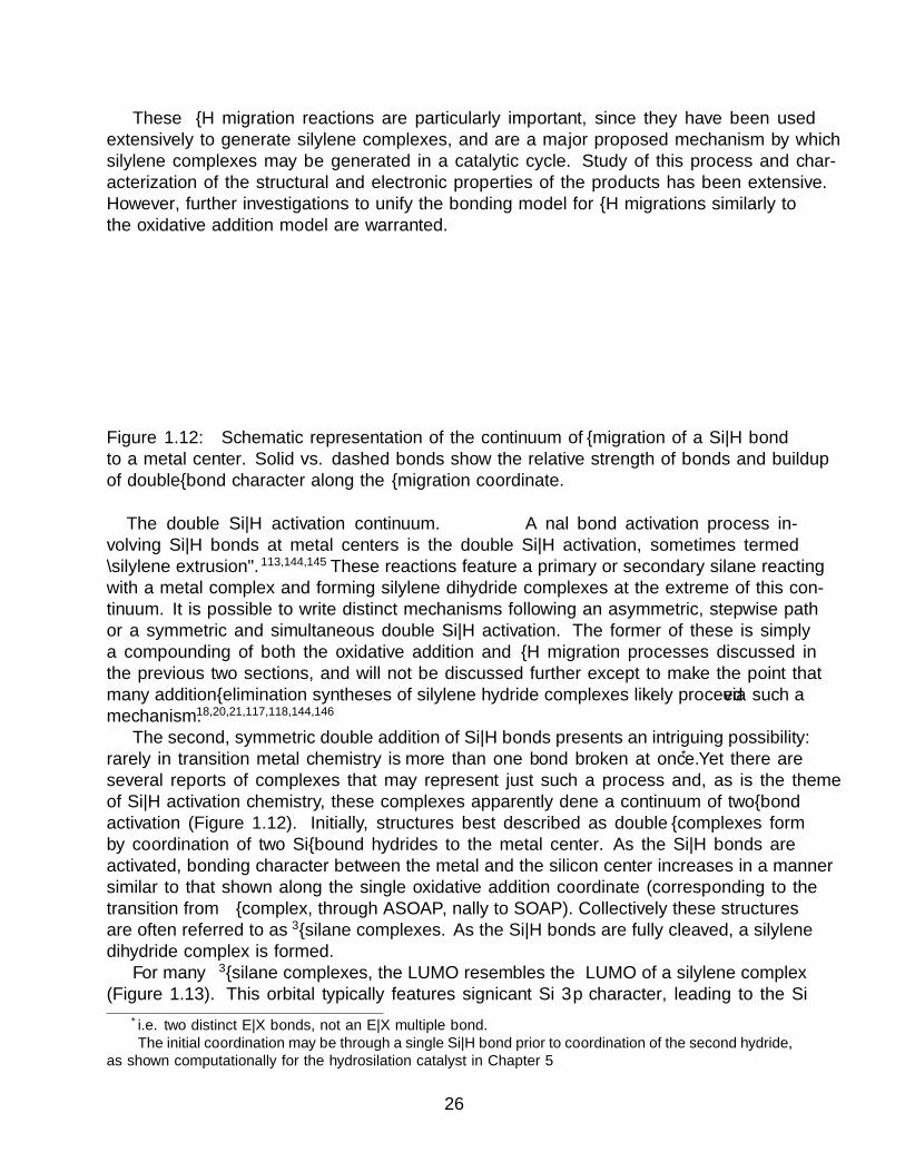
These α–H migration reactions are particularly important, since they have been usedextensively to generate silylene complexes, and are a major proposed mechanism by whichsilylene complexes may be generated in a catalytic cycle. Study of this process and char-acterization of the structural and electronic properties of the products has been extensive.However, further investigations to unify the bonding model for α–H migrations similarly tothe oxidative addition model are warranted.
LnM
increasing silane activation
free silane silane double σ complex η3 silane complex full double addition
SiR2
H
H
LnM SiR2
H
H
LnM SiR2
H
H
LnM SiR2
H
H
Figure 1.12: Schematic representation of the continuum of α–migration of a Si—H bondto a metal center. Solid vs. dashed bonds show the relative strength of bonds and buildupof double–bond character along the α–migration coordinate.
The double Si—H activation continuum. A final bond activation process in-volving Si—H bonds at metal centers is the double Si—H activation, sometimes termed“silylene extrusion”.113,144,145 These reactions feature a primary or secondary silane reactingwith a metal complex and forming silylene dihydride complexes at the extreme of this con-tinuum. It is possible to write distinct mechanisms following an asymmetric, stepwise pathor a symmetric and simultaneous double Si—H activation. The former of these is simplya compounding of both the oxidative addition and α–H migration processes discussed inthe previous two sections, and will not be discussed further except to make the point thatmany addition–elimination syntheses of silylene hydride complexes likely proceed via such amechanism.18,20,21,117,118,144,146
The second, symmetric double addition of Si—H bonds presents an intriguing possibility:rarely in transition metal chemistry is more than one bond broken at once.* Yet there areseveral reports of complexes that may represent just such a process and, as is the themeof Si—H activation chemistry, these complexes apparently define a continuum of two–bondactivation (Figure 1.12). Initially, structures best described as double σ–complexes formby coordination of two Si–bound hydrides to the metal center.� As the Si—H bonds areactivated, bonding character between the metal and the silicon center increases in a mannersimilar to that shown along the single oxidative addition coordinate (corresponding to thetransition from σ–complex, through ASOAP, finally to SOAP). Collectively these structuresare often referred to as η3–silane complexes. As the Si—H bonds are fully cleaved, a silylenedihydride complex is formed.
For many η3–silane complexes, the LUMO resembles the π∗ LUMO of a silylene complex(Figure 1.13). This orbital typically features significant Si 3p character, leading to the Si
*i.e. two distinct E—X bonds, not an E—X multiple bond.�The initial coordination may be through a single Si—H bond prior to coordination of the second hydride,
as shown computationally for the hydrosilation catalyst in Chapter 5
26

centered Lewis acidity observed in many such complexes,13,14,114,147–151 Upon coordination ofa Lewis base, changes in the orbital manifold occur to form either structures further alongthe double Si—H activation continuum11 or trigger an increase in coordination number atSi by inducing an interligand interaction with another M–bound H ligand.147,150
Figure 1.13: The largely Si 3p–based LUMO of BP3
PhRu(H)(η3−H2SiR2) calculated at the B3PW91//6–31G(d,p)/LANL2DZ level of the-ory. Adapted with permission.147
This Lewis acidity has been exploited to developcatalytic applications for η3–silane or silylene dihy-dride complexes. This was first realized for theRu base–stabilized silylene dihydride complex, Cp∗-(iPr3P)(H)2RuSi(H)Ph(OEt2)+ (1.19).11 This com-plex dissociates Et2O to form the base–free com-plex Cp∗(iPr3P)(H)2RuSi(H)Ph+ which is an ac-tive olefin hydrosilation catalyst,11,152 an analogue ofwhich, Cp∗(iPr3P)(H)2RuSi(H)Mes+ (1.34) was sub-sequently isolated and crystallographically character-ized.13 Other catalyst systems based on Ir12,107 andmore recently Fe (Chapter 5) silylene–like complexeshave also been reported.* A hallmark of these cata-lysts is their selectivity for primary silane substrates,with only secondary products observed; additionallya marked selectivity for linear (anti–Markovnikov)products has been observed for all the reported cata-lysts; this is perhaps a result of the Siδ+—Hδ− polarityof the bond adding across the olefin.
These complexes have been proposed to catalyzehydrosilation by a mechanism which involves Si—Cbond formation via a direct addition of an Si—H bond across the olefin substrate in a reactionthat resembles hydroboration (Figure 1.14).11,152,153 This reactivity has been attributed to ahigh degree of positive charge (leading to enhanced electrophilicity) at Si; for example, whilethe cationic osmium silylene complex 1.20 adds its terminal Si—H bond across an olefin (forexample 3–hexene to form 1.21), the neutral silylene complex Cp∗(iPr3P)(H)Os––Si(H)Trip(1.35) has shown no reactivity towards olefins.20 The subsequent silane exchange has beeninvestigated by both computational and experimental methods. While early computationsproposed an associative silane exchange mechanism,152,153 subsequent experimental investi-gations including kinetics of the full catalytic cycle for 1.34 and Eyring analysis of thesekinetics experiments implicates a dissociative mechanism;13 this was also found to be thecase for the hydrosilation catalysis described in Chapter 5.
Neutral η3–silane complexes of Ru are also active catalysts for hydrosilation of unsat-urated substrates, including ketones,150 isocyanides,151 and olefins. These processes havebeen shown to result from the high electrophilicity of the Si centers, leading to hypercoordi-nate structures wherein the substrate is bound to the Si center. For ketone substrates, unliketheir cationic counterparts these complexes are not entirely selective for the formation of sec-
*The Ir system is not a silylene dihydride complex, but rather a silylene monohydride; while there areimplications for this with respect to the silane exchange discussed below, otherwise the reactions catalyzedby this system conserve all the features of the Ru system.
27

LnM Si
H
H
R
H
LnM Si
H
H
R
HR'
LnM Si
H
H
R
R'
MLn
R'
H
RH2SiR'
H
RSiH3i
iiiii
iv
Figure 1.14: Proposed mechanism for hydrosilation by cationic silylene complexes andsome η3–silane complexes. i. Coordination of olefin substrate to the highly electrophilic Sicenter. ii. Direct addition of the terminal Si—H bond on the silylene or silane ligand acrossthe olefin; at this stage the Si—H bonds coordinated to the metal center have been largelyruptured. iii. Loss of substrate by a dissociative mechanism; this step has been implicatedfor M = Ru, Fe. iv. Recoordination of the silane substrate and double Si—H bond activationby the metal center to regenerate the catalyst.
28

ondary silane products; a further, slower hydrosilation process was observed that producedtertiary silane products. This is apparently the result of a competing Chalk–Harrod–likemechanism operating in addition to a cationic silylene–like mechanism.
1.6 Summary
The differences in chemistry observed upon moving down group 14 from C to transitionmetal–Si systems can be attributed to a single factor: the ratio of the radii of the 3p and3s orbitals on Si is significantly larger than the ratio of the corresponding 2p and 2s orbitalradii for C. Emergent from this is the difference in electronegativity of the two elements,and a reversal of the E—H bond polarity between E = C and E = Si. A similar reversal inthe polarities of M—C vs. M—Si bonds is also possible, and seems to occur for the latertrantsition metals while early metals retain a partial negative charge on silyl Si centers.This reversal in bond polarities is manifested in reactions with nucleophiles and carbonylinsertions.
An unusual result of this reversal in bond polarity is the extensive residual interactionsSi engages in with other M–bound ligands, particularly hydrides. While the organometallicchemistry of C typically features well–defined structures and bonding due to repulsive inter-actions between typically partially–negatively charged H and hydrocarbyl ligands, the morefavorable situation of Hδ – ···Siδ+ leads to bond activation coordinates that feature continuaof geometric and electronic structures for different compounds. These include, but are notlimited to, oxidative additions, α–H migrations, and double Si—H bond activations. Theseprocesses have been exploited to develop novel catalytic transformations, e.g. hydrosilation.
1.7 References
[1] Okazaki, M.; Tobita, H.; Ogino, H. Reactivity of silylene complexes. Dalt. Trans. 2003,493–506.
[2] Waterman, R.; Hayes, P. G.; Tilley, T. D. Synthetic development and chemical reactivityof transition–metal silylene complexes. Acc. Chem. Res. 2007, 40, 712–719.
[3] Ogino, H. Synthesis of silylene and silyl(silylene)metal complexes. Chem. Rec. 2002, 2,291–306.
[4] Lickiss, P. D. Transition metal complexes of silylenes, silenes, disilenes, and relatedspecies. Chem. Soc. Rev. 1992, 21, 271.
[5] Lappert, M. F. The coordination chemistry of bivalent group IV donors; Nucleophilic-carbene and dialkylstannylene complexes. J. Organomet. Chem. 1975, 100, 139–159.
[6] Petz, W. Transition–Metal Complexes with Derivatives of Divalent Silicon, Germanium,Tin, and Lead as Ligands. Chem. Rev. 1986, 86, 1019–1047.
[7] Lappert, M. F.; Rowe, R. S. The role of group 14 element carbene analogues in transitionmetal chemistry. Coord. Chem. Rev. 1990, 100, 267–292.
29

[8] Yamamoto, K.; Okinoshima, H.; Kumada, M. Disproportionation of Pentamethyldis-ilane and sym–tetramethyldisilane Catalysed by Platinum Complexes. J. Organomet.Chem. 1970, 23, C7–C8.
[9] Goikhman, R.; Milstein, D. Reactivity of rhodium-triflate complexes with diphenylsi-lane: Evidence for silylene intermediacy in stoichiometric and catalytic reactions. Chem.Eur. J. 2005, 11, 2983–2988.
[10] Gigler, P.; Bechlars, B.; Herrmann, W. A.; Kuhn, F. E. Hydrosilylation with biscarbeneRh(I) complexes: Experimental evidence for a silylene–based mechanism. J. Am. Chem.Soc. 2011, 133, 1589–1596.
[11] Glaser, P. B.; Tilley, T. D. Catalytic Hydrosilylation of Alkenes by a Ruthenium SilyleneComplex. Evidence for a New Hydrosilylation Mechanism. J. Am. Chem. Soc. 2003,125, 13640–13641.
[12] Calimano, E.; Tilley, T. D. Synthesis and structure of PNP–supported iridium silyl andsilylene complexes: Catalytic hydrosilation of alkenes. J. Am. Chem. Soc. 2009, 131,11161–11173.
[13] Fasulo, M. E.; Lipke, M. C.; Tilley, T. D. Structural and mechanistic investigation ofa cationic hydrogen-substituted ruthenium silylene catalyst for alkene hydrosilation.Chem. Sci. 2013, 4, 3882–3887.
[14] Lipke, M. C.; Liberman-Martin, A. L.; Tilley, T. D. Electrophilic Activation of Silicon–Hydrogen Bonds in Catalytic Hydrosilations. Angew. Chem. Int. Ed. 2017, 56, 2260–2294.
[15] Schmid, G.; Welz, E. Base–Stabilized Silyleneiron Complexes. Angew. Chem. Int. Ed.1977, 16, 785–786.
[16] Zybill, C.; Muller, G. Synthesis and Structure of [(OC)4Fe––Si(OtBu)2 ·HMPT], aDonor–Stabilized Silanediyl(“Silylene”) Complex. Angew. Chem. Int. Ed. 1987, 26,669–670.
[17] Tobita, H.; Ueno, K.; Ogino, H. Mechanistic Study on the Photochemical Conversionof Disalanyliron(II) Complexes to Monosilyliron(II) Complexes. Bull. Chem. Soc. Jpn.1988, 61, 2797–2804.
[18] Sakurai, H.; Kamiyama, Y.; Nakadaira, Y. Dimethylsilanediyliron Complexes. Angew.Chem. Int. Ed. 1978, 17, 674–675.
[19] Tobita, H.; Mutsuda, A.; Hashimoto, H.; Ueno, K.; Ogino, H. Direct Evidence forExtremely Facile 1,2– and 1,3–Group Migrations in an FeSi2 System. Angew. Chem.Int. Ed. 2003, 43, 221–224.
[20] Hayes, P. G.; Beddie, C.; Hall, M. B.; Waterman, R.; Tilley, T. D. Hydrogen–substitutedosmium silylene complexes: Effect of charge localization on catalytic hydrosilation. J.Am. Chem. Soc. 2006, 128, 428–429.
30

[21] Hayes, P. G.; Waterman, R.; Glaser, P. B.; Tilley, T. D. Synthesis, structure, andreactivity of neutral hydrogen–substituted ruthenium silylene and germylene complexes.Organometallics 2009, 28, 5082–5089.
[22] Iota, V.; Yoo, C. S.; Cynn, H. Quartzlike carbon dioxide: An optically nonlinear ex-tended solid at high pressures and temperatures. Science (80-. ). 1999, 283, 1510–1513.
[23] Durrant, M. C. A quantitative definition of hypervalency. Chem. Sci. 2015, 6, 6614–6623.
[24] Noury, S.; Silvi, B.; Gillespie, R. J. Chemical bonding in hypervalent molecules: Is theoctet rule relevant? Inorg. Chem. 2002, 41, 2164–2172.
[25] Muller, R.; Heinrich, L. Uber Silikone, LII Der Nachweis und die Abtrennung vonAlkoxo– und Aroxo– Verbindungen mit fiinfbindigem Silicium. Chem. Ber. 1961, 94,1943–1951.
[26] Chuit, C.; Corriu, R. J.; Reye, C.; Young, J. C. Reactivity of Penta– and HexacoordinateSilicon Compounds and Their Role as Reaction Intermediates. Chem. Rev. 1993, 93,1371–1448.
[27] Rendler, S.; Oestreich, M. Hypervalent Silicon as a Reactive Site in Selective Bond-Forming Processes. Synthesis 2005, 2005, 1727–1747.
[28] Voronkov, M. G.; Trofimova, O. M.; Bolgova, Y. I.; Chernov, N. F. Hypervalent silicon–containing organosilicon derivatives of nitrogen heterocycles. Russ. Chem. Rev. 2007,76, 825–845.
[29] Kano, N. Organosilicon Compd. Theory Exp.; Elsevier Inc., 2017; pp 645–716.
[30] Liberman-Martin, A. L.; Bergman, R. G.; Tilley, T. D. Lewis acidity of bis(perfluoro-catecholato)silane: Aldehyde hydrosilylation catalyzed by a neutral silicon compound.J. Am. Chem. Soc. 2015, 137, 5328–5331.
[31] Saillard, J. Y.; Hoffmann, R. C—H and H—H Activation in Transition Metal Complexesand on Surfaces. J. Am. Chem. Soc. 1984, 106, 2006–2026.
[32] Graham, W. A. G. From silicon–hydrogen to carbon–hydrogen activation. J. Organo-met. Chem. 1986, 300, 81–91.
[33] Rest, A. J.; Whitwell, I.; Graham, W. A. G.; Hoyano, J. K.; Mcmaster, A. D. Pho-toactivation of Methane by η5−Cyclopentadienyl and Substituted η5−CyclopentadienylGroup 8 Metal Dicarbonyl Complexes, [M(η5−C5R5)– (CO)2] (M = Rh or Ir, R = Hor Me), and Dicarbonyl(η5−indenyl)iridium: A Matrix Isolation. J. Chem. Soc. Dalt.Trans. 1987, 1181–1190.
[34] Weller, A. S.; Chadwick, F. M.; McKay, A. I. Transition Metal Alkane–Sigma Com-plexes: Synthesis, Characterization, and Reactivity Adv. Organomet. Chem., 2016; 66 ;pp 223–276.
31

[35] Kubas, G. J. Activation of dihydrogen and coordination of molecular H2 on transitionmetals. J. Organomet. Chem. 2014, 751, 33–49.
[36] Pauling, L. The nature of the chemical bond. IV. The energy of single bonds and therelative electronegativity of atoms. J. Am. Chem. Soc. 1932, 54, 3570–3582.
[37] Mulliken, R. S. A new electroaffinity scale; Together with data on valence states and onvalence ionization potentials and electron affinities. J. Chem. Phys. 1934, 2, 782–793.
[38] Mulliken, R. S. Electronic structures of molecules XI. Electroaffinity, molecular orbitalsand dipole moments. J. Chem. Phys. 1935, 3, 573–585.
[39] Kaupp, M. The Role of Radial Nodes of Atomic Orbitals for Chemical Bonding and thePeriodic Table. J. Comput. Chem. 2006, 28, 320–325.
[40] Kutzelnigg, W. Chemical Bonding in Higher Main Group Elements. Angew. ChemieInt. Ed. English 1984, 23, 272–295.
[41] Pyykko, P. Dirac-fock one-centre calculations part 8. The 1Σ states of ScH, YH, LaH,AcH, TmH, LuH and LrH. Phys. Scr. 1979, 20, 647–651.
[42] Desclaux, J. P. Relativistic Dirac-Fock expectation values for atoms with Z = 1 to Z =120. At. Data Nucl. Data Tables 1973, 12, 311–406.
[43] Pevney, J. The Devil in the Dark. Star Trek, 1967.
[44] Pace, N. R. The universal nature of biochemistry. Proc. Natl. Acad. Sci. U.S.A. 2010,98, 805–808.
[45] Olbrich, G.; Potzinger, P.; Reimann, B.; Walsh, R. Decomposition Channels ofChemically Activated Disilane. The π Bond Energy of Disilene and Its Derivatives.Organometallics 1984, 3, 1267–1272.
[46] Lange, N. A.; Dean, J. A. Lange’s Handbook of Chemistry ; 1999.
[47] Miller, S. I. Dissociation energies of π bonds in alkenes. J. Chem. Educ. 1978, 55,778–780.
[48] Jutzi, P. New Element-Carbon (p–p)π Bonds. Angew. Chemie Int. Ed. 1975, 1, 232–245.
[49] West, R. Multiple bonds to silicon: 20 years later. Polyhedron 2002, 21, 467–472.
[50] Brook, A. G.; Abdesaken, F.; Gutekunst, B.; Gutekunst, G.; Kallury, R. K. A solidsilaethene: isolation and characterization. Chem. Comm. 1981, 191–192.
[51] West, R.; Fink, M. J.; Michl, J. Tetramesityldisilene, a Stable Compound Containing aSilicon–Silicon Double Bond. Science (80-. ). 1981, 214, 1343–1344.
[52] Raabe, G.; Michl, J. Multiple Bonding to Silicon. Chem. Rev. 1985, 85, 419–509.
32

[53] West, B. R. Chemistry of the Silicon–Silicon Double Bond. Angew. Chemie Int. Ed.1987, 26, 1201–1211.
[54] West, R.; Buffy, J. J.; Haaf, M.; Muller, T.; Gehrhus, B.; Lapper, M. F.; Apeloig, Y.Chemical shift tensors and NICS calculations for stable silylenes. J. Am. Chem. Soc.1998, 120, 1639–1640.
[55] Tilley, T. D. In Silicon-Heteroatom Bond ; Patai, S., Ed.; John Wiley & Sons: Chippen-ham, 1991; Chapter 9, pp 245–307.
[56] Lichtenberger, D. L.; Rai-Chaudhuri, A. Electronic Structure of Transition Metal–Silicon Bonds. Valence Photoelectron Spectra of (η5 –C5H5)Fe(CO)2L Complexes (L= SiC13, Si(CH3)3). J. Am. Chem. Soc. 1991, 113, 2923–2930.
[57] Hubler, K.; Hunt, P. A.; Maddock, S. M.; Rickard, C. E. F.; Roper, W. R.; Salter, D. M.;Schwerdtfeger, P.; Wright, L. J. Examination of Metal–Silicon Bonding through Struc-tural and Theoretical Studies of an Isostructural Set of Five–Coordinate Silyl Com-plexes, Os(SiR3)Cl(CO)(PPh3)3 (R = F, Cl, OH, Me). Organometallics 1997, 16, 5076–5083.
[58] Cradock, S.; Ebsworth, E. A. V.; Robertson, A. Photoelectron Spectra of Some Silyland Germyl Transition–metal Carbonyls and Related Species. J. Chem. Son - Dalt.Trans. 1973, 22–26.
[59] Novak, I.; Huang, W.; Luo, L.; Huang, H. H.; Ang, H. G.; Zybill, C. E. UPS Studyof Compounds with MetalSilicon Bonds: M(CO)nSiCl3 (M = Co, Mn; n = 4, 5) andFe(CO)4 (SiCl3)2. Organometallics 1997, 16, 1567–1572.
[60] Hoffmann, R.; Alvarez, S.; Mealli, C.; Falceto, A.; Cahill, T. J.; Zeng, T.; Manca, G.From Widely Accepted Concepts in Coordination Chemistry to Inverted Ligand Fields.Chem. Rev. 2016, 116, 8173–8192.
[61] Walroth, R. C.; Lukens, J. T.; MacMillan, S. N.; Finkelstein, K. D.; Lancaster, K. M.Spectroscopic Evidence for a 3d10 Ground State Electronic Configuration and LigandField Inversion in [Cu(CF3)4]1– . J. Am. Chem. Soc. 2016, 138, 1922–1931.
[62] Gray, H. B. Electrons and chemical bonding ; W. A. Benjamin, Inc.: New York, 1965.
[63] Tsegaw, Y. A.; Kadam, P. E.; Sanchez-garcia, E.; Sander, W. Is Magnetic Bistabilityof Carbenes a General Phenomenon? Isolation of Simple Aryl(trifluoromethyl)carbenesin Both Their Singlet and Triplet States. 2017,
[64] de Fremont, P.; Marion, N.; Nolan, S. P. Carbenes: Synthesis, properties, andorganometallic chemistry. Coord. Chem. Rev. 2009, 253, 862–892.
[65] Santamarıa, J.; Aguilar, E. Beyond Fischer and Schrock carbenes: Non–heteroatom–stabilized group 6 metal carbene complexes — a general overview. Org. Chem. Front.2016, 3, 1561–1588.
33

[66] Nakata, N.; Fujita, T.; Sekiguchi, A. A stable Schrock–type hafnium–silylene complex.J. Am. Chem. Soc. 2006, 128, 16024–16025.
[67] Lee, V. Y.; Aoki, S.; Yokoyama, T.; Horiguchi, S.; Sekiguchi, A.; Gornitzka, H.;Guo, J. D.; Nagase, S. Toward a silicon version of metathesis: From schrock–type tita-nium silylidenes to silatitanacyclobutenes. J. Am. Chem. Soc. 2013, 135, 2987–2990.
[68] Nakatsuji, H.; Ushio, J.; Yonezawa, T. Does a Silylene–Metal Complex Exist? J.Organomet. Chem. 1983, 258, C1–C4.
[69] Ueno, K.; Tobita, H.; Shimoi, M.; Ogino, H. Synthesis, characterization, and X–raycrystal structure of a donor–stabilized bis(silylene)iron complex. J. Am. Chem. Soc.1988, 110, 4092–4093.
[70] Cundari, T. R.; Gordon, M. S. Nature of the transition metal–silicon double bond. J.Phys. Chem. 1992, 96, 631–636.
[71] Marquez, A.; Sanz, J. F. Electronic Structure of the Transition–Metal–Carbene-likeComplexes (CO)5Mo–M′H2 (M′ = C, Si, Ge, and Sn). A Theoretical Study Based onab Initio CASSCF Calculations. J. Am. Chem. Soc. 1992, 114, 2903–2909.
[72] Piper, T. S.; Lemal, D.; Wilkinson, G. A silyliron compound; an Fe—Si σ bond. Natur-wissenschaften 1956, 43, 129.
[73] Tamao, K.; Kawachi, A.; Sun, G. R. Palladium–Catalyzed Skeletal Rearrangement of(Alkoxy)oligosilanes via Silylene Transfer. J. Am. Chem. Soc. 1995, 117, 8043–8044.
[74] Marschner, C. Organosilicon Compd. Theory Exp.; Elsevier Inc., 2017; pp 295–360.
[75] Woo, H. G.; Tilley, T. D. σ–Bond Metathesis Reactions of Si—H and M—Si Bonds.New Routes to d0 Metal Silyl Complexes. J. Am. Chem. Soc. 1989, 111, 3757–3758.
[76] Corey, J. Y. Reactions of Hydrosilanes with Transition Metal Complexes. Chem. Rev.2016, 116, 11291–11435.
[77] Corey, J. Y. Reactions of Hydrosilanes with Transition Metal Complexes and Charac-terization of the Products. Chem. Rev. 2011, 111, 863–1071.
[78] Corey, J. Y.; Braddock-Wilking, J. Reactions of hydrosilanes with transition–metalcomplexes: Formation of stable transition–metal silyl compounds. Chem. Rev. 1999,99, 175–292.
[79] Schubert, U.; Scholz, G.; Muller, J.; Ackermann, K.; Worle, B.; Stansfield, R. Hydrido–silyl–komplexe. J. Organomet. Chem. 1986, 306, 303–326.
[80] Bakhmutov, V. I.; Howard, J. A. K.; Keen, D. A.; Kuzmina, L. G.; Leech, M. A.;Nikonov, G. I.; Vorontsov, E. V.; Wilson, C. C. Combined single crystal neutron diffrac-tion and solution NMR relaxation studies of mono– and bis(silyl) substituted niobocenehydrides with nonclassical interligand interactions. J. Chem. Soc. Dalt. Trans. 2000,1631–1635.
34

[81] Dubberley, S. R.; Ignatov, S. K.; Rees, N. H.; Razuvaev, A. G.; Mountford, P.;Nikonov, G. I. Are J(Si—H) NMR coupling constants really a probe for the existenceof nonclassical H—Si interactions? J. Am. Chem. Soc. 2003, 125, 642–643.
[82] Ignatov, S. K.; Rees, N. H.; Tyrrell, B. E.; Dubberley, S. R.; Razuvaev, A. G.; Mount-ford, P.; Nikonov, G. I. Nonclassical titanocene silyl hydrides. Chem. - A Eur. J. 2004,10, 4991–4999.
[83] McGrady, G. S.; Sirsch, P.; Chatterton, N. P.; Ostermann, A.; Gatti, C.; Alt-mannshofer, S.; Herz, V.; Eickerling, G.; Scherer, W. Nature of the bonding in metal–silane σ–complexes. Inorg. Chem. 2009, 48, 1588–1598.
[84] Scherer, W.; Meixner, P.; Barquera-lozada, J. E.; Hauf, C.; Obenhuber, A.; Bruck, A.;Wolstenholme, D. J.; Ruhland, K.; Leusser, D. A Unifying Bonding Concept for MetalHydrosilane Complexes. Angew. Chem. Int. Ed. 2013, 52, 6092–6096.
[85] Horbatenko, Y.; Vyboishchikov, S. F. Si···H Interligand Interactions in Cobalt(V) andIridium(V) Bis(silyl)bis(hydride) Complexes. Chempluschem 2013, 78, 1073–1081.
[86] Scherer, W.; Meixner, P.; Batke, K.; Barquera-Lozada, J. E.; Ruhland, K.; Fischer, A.;Eickerling, G.; Eichele, K. J(Si,H) Coupling Constants in Nonclassical Transition–MetalSilane Complexes. Angew. Chemie - Int. Ed. 2016, 55, 11673–11677.
[87] Woo, H. G.; Walzer, J. F.; Tilley, T. D. A σ–Bond Metathesis Mechanism for Dehy-dropolymerization of Silanes to Polysilanes by d0 Metal Catalysts. J. Am. Chem. Soc.1992, 114, 7047–7055.
[88] Sadow, A. D.; Tilley, T. D. Catalytic functionalization of hydrocarbons by σ-bond-metathesis chemistry: Dehydrosilylation of methane with a scandium catalyst. Angew.Chem. Int. Ed. 2003, 42, 803–805.
[89] Wu, F.; Jordan, R. F. Sigma–bond metathesis reactions of zirconocene alkyl cationswith phenylsilane. Organometallics 2005, 24, 2688–2697.
[90] Colomer, R.; Corriu, R. J. P.; Vioux, A. Synthesis and Properties of Manganese HydridesHaving a Finctional Silicon. Inorg. Chem. 1979, 18, 695–700.
[91] Pannell, K. H.; Rozell, J. M.; Lii, J.; Tien-Mayr, S. Y. Organometalloidal derivativesof the transition metals. Part 18. Transition–metal–substituted silanes. Hydrosilylationof phenylacetylene using [η5−C5H5)Fe(CO)2SiPh2H] and [(η5−C5H4SiPh2H)Fe(CO)2R](R = Me, SiMe3). Organometallics 1988, 7, 2524–2528.
[92] Cundy, C. S.; Kingston, B. M.; Lappert, M. F. Organometallic Complexes with Silicon–Transition Metal or Silicon–Carbon–Transition Metal Bonds. Adv. Organomet. Chem.1973, 11, 253–330.
[93] Braunstein, P.; Knorr, M. Reactivity of the metal–silicon bond in organometallic chem-istry. J. Organomet. Chem. 1995, 500, 21–38.
35

[94] Tanabe, M.; Osakada, K. Organosilicon Compd.; Elsevier Inc., 2017; pp 31–68.
[95] Hagen, A. P.; Higgins, C. R.; Russo, P. J. Silyltricarbonyl–π–cyclopentadienylchromium,–molybdenum, and –tungsten. Inorg. Chem. 1971, 10, 1657–1660.
[96] H., S.; MacDiarmid, A. G. Silylphosphonium Compounds. Synthesis and Structure.Inorg. Chem. 1976, 15, 848–856.
[97] Cerveau, G.; Colomer, E.; Corriu, R.; Douglas, W. E. Preparation et Reactivite de Com-poses Chiraux et non Chiraux Derives de (η5−cyclopentadienyl) dicarbonylfer. Stere-ochimie de la Coupure de la Liaison Fer–Silicium. J. Organomet. Chem. 1977, 135,373–386.
[98] Colomer, E.; Corriu, R. J. P. On the Behaviour of an Optically Active Cobalt–Silicon Bond. Evidence for the Formation of Analogues of Silyl–Grignard Reagents.J. Organomet. Chem. 1977, 133, 159–168.
[99] Kingston, B. M.; Lappert, M. F. Binuclear Organometallic Compouns. Part VI. Com-plexes containing Metal–Metal Bonds Between Elements of Group IVA and Group IVB.J. Chem. Soc. Dalt. Trans. 1972, 69–73.
[100] Tilley, T. D. Trimethylsilyl Derivatives of Bis(cyclopentadienyl)zirconium and –haf-nium. Crystal Structure of (η5−C5H5)2Zr(SiMe3)(S2CNEt2). Organometallics 1985, 4,1452–1457.
[101] Gladysz, J. A. New Synthetic Chemistry of Transition-Metal Trialkylsilane Complexes.Acc. Chem. Res. 1984, 17, 326–332.
[102] Johnson, D. L.; Gladysz, J. A. Reactions of Benzaldehyde with Trialkylsilyl MetalCarbonyl Complexes. J. Am. Chem. Soc. 1979, 101, 6433–6435.
[103] Johnson, D.; Gladysz, J. Reactions of (CO)5MnSi(CH3)3 with organic carbonyl com-pounds. Inorg. Chem. 1981, 20, 2508–2515.
[104] Arnold, J.; Tilley, T. D. Insertion of Organic Carbonyls Into The Tantalum-silicon Bond of (η5-C5Me5)Cl3TaSiMe3: Preparation and Characterization of The A-silylalkoxides ((η5-C5Me5)Cl3TaOCRR′SiMe3. J. Am. Chem. Soc. 1987, 109, 3318–3322.
[105] Sakaki, S.; Mizoe, N.; Sugimoto, M. Theoretical study of platinum(0)–catalyzed hy-drosilylation of ethylene. Chalk–Harrod mechanism or modified Chalk–Harrod mecha-nism. Organometallics 1998, 17, 2510–2523.
[106] Tobita, H.; Ueno, K.; Ogino, H. Photochemical Conversion of Disilanyliron(II) Com-plexes to Monosilyliron(II) Complexes. Chem. Lett. 1986, 15, 1777–1780.
[107] Calimano, E.; Tilley, T. D. Alkene Hydrosilation by a Cationic Hydrogen–SubstitutedIridium Silylene Complex. J. Am. Chem. Soc. 2008, 130, 9226–9227.
36

[108] Straus, D. A.; Tilley, T. D.; Rheingold, A. L.; Geib, S. J. Preparation, Characterization,and X–ray Crystal Structure of an Acetonitrile–Complexed Ruthenium Silylene. J. Am.Chem. Soc. 1987, 109, 5872–5873.
[109] Straus, D. A.; Zhang, C.; Quimbita, G. E.; Grumbine, S. D.; Heyn, R. H.; DonTilley, T.; Rheingold, A. L.; Geib, S. J. Silyl and Diphenylsilylene Derivatives of (η5−C5Me5)(PMe3)2Ru. Evidence for the Base-Free Silylene Complex [(η5−C5Me5)(PMe3)2-Ru––SiPh2]+. J. Am. Chem. Soc. 1990, 112, 2673–2681.
[110] Straus, D. A.; Grumbine, S. D.; Don Tilley, T. Base-Free Silylene Complexes[(η5−C5Me5)(PMe3)2Ru––Si(SR)2]BPh4 (R = Et, p –MeC6H4). J. Am. Chem. Soc.1990, 112, 7801–7802.
[111] Grumbine, S. K.; Tilley, T. D.; Arnold, F. P.; Rheingold, A. L. Base–Free Silylene Com-plexes without π–Donor Stabilization. Molecular Structure of [Cp∗(PMe3)2Ru––SiMe2][B(C6F5)4]. J. Am. Chem. Soc. 1994, 116, 5495–5496.
[112] Mitchell, G. P.; Tilley, T. D. Generation of a Silylene Complex by the 1,2–Migrationof Hydrogen from Silicon to Platinum. Angew. Chem. Int. Ed. 1998, 37, 2524–2526.
[113] Peters, J. C.; Feldman, J. D.; Tilley, T. D. Silylene extrusion from a silane: Directconversion of Mes2SiH2 to an iridium silylene dihydride [1]. J. Am. Chem. Soc. 1999,121, 9871–9872.
[114] Thomas, C. M.; Peters, J. C. An η3−H2SiR2 Adduct of [{PhB(CH2PiPr2)3}FeIIH].Angew. Chem. Int. Ed. 2006, 45, 776–780.
[115] Iluc, V. M.; Hillhouse, G. L. Arrested 1,2–hydrogen migration from silicon to nickelupon oxidation of a three–coordinate Ni(I) silyl complex. J. Am. Chem. Soc. 2010, 132,11890–11892.
[116] Price, J. S.; Emslie, D. J. H.; Britten, J. F. Manganese Silylene Hydride Complexes:Synthesis and Reactivity with Ethylene to Afford Silene Hydride Complexes. Angew.Chem. Int. Ed. 2017, 56, 6223–6227.
[117] Smith, P. W.; Tilley, T. D. Base–Free Iron Hydrosilylene Complexes via an α–HydrideMigration that Induces Spin Pairing. J. Am. Chem. Soc. 2018, 140, 3880–3883.
[118] Watanabe, T.; Hashimoto, H.; Tobita, H. Hydrido(hydrosilylene)tungsten Complexeswith Strong Interactions between the Silylene and Hydrido Ligands. Angew. Chemie -Int. Ed. 2003, 43, 218–221.
[119] Ueno, K.; Nakano, K.; Ogino, H. Synthesis of a Donor–Stabilized Silyl(silylene)ironComplex. Direct Observation of 1,3–Methyl Migration from Silyl to Silylene Ligands.Chem. Lett. 1996, 459–460.
[120] Pannell, K. H.; Cervantes, J.; Hernandez, C.; Cassias, J.; Vincent, S. Polysllane–MetalInteractions. Photochemical Deollgomerizations and Base Treatment Migrations fromIron to Cyclopentadienyl Ligands. Organometallics 1986, 5, 1056–1057.
37

[121] Pannell, K. H.; Wang, L. J.; Rozell, J. M. Photochemical Skeletal Redistributions ofPermethylated Linear and Cyclic Oligosilyl Groups in (η5−C5H5)Fe(CO)2–SubstitutedOligosilanes. Organometallics 1989, 8, 550–552.
[122] Pannell, K. H.; Rozell, J. M.; Hernandez, C. Synthesis and Photochemical Deoligo-merizations of a Series of Isomeric Disilyliron Complexes: (η5−C5H5)Fe(CO)2Si2Ph3–n-Me2+n . J. Am. Chem. Soc. 1989, 111, 4482–4485.
[123] Ueno, K.; Tobita, H.; Ogino, H. Evidence for Equilibration of 1,3–Alkyl Migration inSilyl(silylene)iron Intermediates. Chem. Lett. 1990, 369–372.
[124] Yamashita, H.; Tanaka, M.; Gtoto, M. Selective Formation of cis –(HMe2Si)2Pt(PEt3)2
from HMe2SiSiMe2H and Pt(PEt3)3 and Its Reactivities Relevant to Generation of(Silylene)platinum Species Thereof. Organometallics 1992, 11, 3227–3232.
[125] Pestana, D. C.; Koloski, T. S.; Berry, D. H. Redistribution of Methyl Groups betweenSilicon Centers in Bis(silyl)tungsten Complexes: Silyl Silylene Complex Intermediatesas the Source of Interligand Reactivity. Organometallics 1994, 13, 4173–4175.
[126] Tanaka, Y.; Yamashita, H.; Tanaka, M. Unexpected Formation of 1,4–Disilacyclohexa–2,5–dienes in the Palladium-Catalyzed Reactions of Cl(SiMe2)3Cl with Acetylenes andIts Application to Polymer Synthesis. Organometallics 1995, 14, 530–541.
[127] Reichl, J. A.; Popoff, C. M.; Gallagher, L. A.; Remsen, E. E.; Berry, D. H. Ruthenium-catalyzed demethanative coupling of HGeMe3: A high yield route to polygermanes. J.Am. Chem. Soc. 1996, 118, 9430–9431.
[128] Mitchell, G. P.; Tilley, T. D.; Yap, G. P.; Rheingold, A. L. Polysilyl Group Iso-merization via Migrations in Rhodium and Iridium Derivatives (Me3P)3MSi(SiMe3)3.Organometallics 1995, 14, 5472–5474.
[129] Wada, H.; Tobita, H.; Ogino, H. Intramolecular Aromatic C—H Bond Activationby a Silylene Ligand in a Methoxy-Bridged Bis ( silylene ) — Ruthenium ComplexIntramolecular Aromatic C—H Bond Activation by a Silylene Ligand in a Methoxy–Bridged Bis(silylene)–Ruthenium Complex. Communications 1997, 721, 2–5.
[130] Scherer, W.; Eickerling, G.; Tafipolsky, M.; McGrady, G. S.; Sirsch, P.; Chatter-ton, N. P. Elucidation of the bonding in Mn(η2−SiH) complexes by charge densityanalysis and T1 NMR measurements: asymmetric oxidative addition and anomeric ef-fects at silicon. Chem. Commun. (Camb). 2006, 1, 2986–2988.
[131] Meixner, P.; Batke, K.; Fischer, A.; Schmitz, D.; Eickerling, G.; Kalter, M.; Ruh-land, K.; Eichele, K.; Barquera-Lozada, J. E.; Casati, N. P. M.; Montisci, F.; Macchi, P.;Scherer, W. J (Si,H) Coupling Constants of Activated Si—H Bonds. J. Phys. Chem. A2017, 121, 7219–7235.
[132] Schubert, U.; Ackermann, K.; Worle, B.; Schubert, U. A Long Si–H Bond or a ShortSi–H Nonbond? Neutron Diffraction Study of (η5−CH3C5H4)(CO)2(H)MnSiF(C6H5)2.J. Am. Chem. Soc. 1982, 104, 7378–7380.
38
[133] Mork, B. V.; Tilley, T. D.; Schultz, A. J.; Cowan, J. A. Silylene hydride com-plexes of molybdenum with silicon–hydrogen interactions: Neutron structure of(η5−C5Me5)(Me2PCH2CH2PMe2) Mo(SiEt2). J. Am. Chem. Soc. 2004, 126, 10428–10440.
[134] Capelli, S. C.; Burgi, H. B.; Dittrich, B.; Grabowsky, S.; Jayatilaka, D. Hirshfeld atomrefinement. IUCrJ 2014, 1, 361–379.
[135] Genoni, A. et al. Quantum Crystallography: Current Developments and Future Per-spectives. Chem. - A Eur. J. 2018,
[136] Nikonov, G. I. Recent Advances in Nonclassical Interligand Si···H Interactions Adv.Organomet. Chem.; 53, 2005, 217–309.
[137] Rabaa, H.; Saillard, J. Y.; Schubert, U. Interaction between a sigma bond and a dn
MLn fragment: an MO analysis of the MnSiH three-center interaction in CpMnL2HSiR3
complexes. J. Organomet. Chem. 1987, 330, 397–413.
[138] Lichtenberger, D. L.; Rai-Chaudhuri, A. Electronic structure factors of silicon–hydrogen bond activation by transition metals. The valence photoelectron spectrumof silylmanganese complex (η5−C5H5)Mn(CO)2HSiCl3. J. Am. Chem. Soc. 1989, 111,3583–3591.
[139] Lichtenberger, D. L.; Rai-Chaudhuri, A. Electronic Structure Control of Si—HBond Activation by Transition Metals. 2. Valence Photoelectron Spectra of (η5−C5H4CH3)Mn(CO)2HSiPh3, (η5−C5H4CH3)Mn(CO)2HSiHPh2, and (η5−C5H4CH3)-Mn(CO)2HSiFPh2 (Ph = C6H5). J. Am. Chem. Soc. 1990, 112, 2492–2497.
[140] Lichtenberger, D. L.; Rai-Chaudhuri, A. Electronic Structure Factors of Si—H BondActivation by Transition Metals. Valence Photoelectron Spectra of (η5−C5H4CH3)Mn-(CO)(PMe3)HSiCl3 and (η5−C5H4CH3)]Mn(CO)(PMe3)HSiHPh2 (Me = CH3, Ph =C6H5). Inorg. Chem. 1990, 29, 975–981.
[141] Lichtenberger, D. L.; Rai-Chaudhuri, A. Cyclopentadienyl ring methylation and its ef-fect on silicon–hydrogen bond activation in (η5−C5H5–n(CH3)n)Mn(CO)2HSiH(C6H5)2
(n = 0, 1, 5) complexes. Organometallics 1990, 9, 1686–1690.
[142] Autschbach, J.; Le Guennic, B. Analyzing and Interpreting NMR Spin–Spin CouplingConstants Using Molecular Orbital Calculations. J. Chem. Educ. 2007, 84, 156.
[143] Nikonov, G. I. New types of non–classical interligand interactions involving siliconbased ligands. J. Organomet. Chem. 2001, 635, 24–36.
[144] Feldman, J. D.; Peters, J. C.; Don Tilley, T. Activations of silanes with [PhB-(CH2PPh2)3]Ir(H)(η3−C8H13). Formation of iridium silylene complexes via the extru-sion of silylenes from secondary silanes R2SiH2. Organometallics 2002, 21, 4065–4075.
39

[145] Rankin, M. A.; MacLean, D. F.; Schatte, G.; McDonald, R.; Stradiotto, M. Sily-lene extrusion from organosilanes via double geminal Si-H bond activation by aCp∗Ru(κ2−P, N)+ complex: Observation of a key stoichiometric step in the Glaser-Tilley alkene hydrosilylation mechanism. J. Am. Chem. Soc. 2007, 129, 15855–15864.
[146] Shinohara, A.; Mcbee, J.; Tilley, T. D. Germylene and Silylene Complexes of Molyb-denum via E—H (E = Ge, Si) Bond Activations: Steric Influences on IntramolecularMoH···EInteractions. Inorg. Chem. 2009, 48, 8081–8083.
[147] Lipke, M. C.; Tilley, T. D. High Electrophilicity at Silicon in η3–Silane σ–Complexes:Lewis Base Adducts of a Silane Ligand, Featuring Octahedral Silicon and Three Ru—H—Si Interactions. J. Am. Chem. Soc. 2011, 133, 16374–16377.
[148] Lipke, M. C.; Tilley, T. D. Stabilization of ArSiH4– and SiH6
2– Anions in DirutheniumSi—H σ–Complexes. Angew. Chem. Int. Ed. 2012, 51, 11115–11121.
[149] Lipke, M. C.; Neumeyer, F.; Tilley, T. D. Interconversion of η3−H2SiRR′ σ–Complexesand 16–Electron Silylene Complexes via Reversible H—H or C—H Elimination. J. Am.Chem. Soc. 2014, 136, 6092–6102.
[150] Lipke, M. C.; Tilley, T. D. Hypercoordinate Ketone Adducts of Electrophilic η3−H2SiRR′ Ligands on Ruthenium as Key Intermediates for Efficient and Robust CatalyticHydrosilation. J. Am. Chem. Soc. 2014, 136, 16387–16398.
[151] Lipke, M. C.; Liberman-martin, A. L.; Tilley, T. D. Significant Cooperativity BetweenRuthenium and Silicon in Catalytic Transformations of an Isocyanide. J. Am. Chem.Soc. 2016, 138, 9704–9713.
[152] Beddie, C.; Hall, M. B. A theoretical investigation of ruthenium–catalyzed alkenehydrosilation: Evidence to support an exciting new mechanistic proposal. J. Am. Chem.Soc. 2004, 126, 13564–13565.
[153] Beddie, C.; Hall, M. B. Do B3LYP and CCSD(T) predict different hydrosilylationmechanisms? Influences of theoretical methods and basis sets on relative energies inruthenium–silylene–catalyzed ethylene hydrosilylation. J. Phys. Chem. A 2006, 110,1416–1425.
40

Chapter 2
Silane–Allyl Coupling Reactions of Cp∗(iPr2MeP)Fe(η3–
allyl) and Synthetic Access to the Hydrido–Dinitrogen
Complex Cp∗(iPr2MeP)FeH(N2)
2.1 Introduction
A well-established and convenient route to ruthenium silylene complexes is based onreaction of a hydrosilane with Cp∗(iPr2MeP)Ru(η3 –CH2Ph), which contains a hemilabilebenzyl leaving group.1 Such reactions lead to rapid Si—H activation, toluene elimination,and H–migration to produce neutral Cp∗(iPr2MeP)RuH(––SiRR′) silylene complexes.2 Thischapter describes initial efforts toward establishing related pathways to reactive Fe–Si com-plexes, with the preparation and isolation of the Fe allyl complex Cp∗(iPr2MeP)Fe(η3 –allyl),(2.1). Reactions of 2.1 with the sterically demanding silanes Mes2SiH2 and DMPSiH3 resultin products derived from Si—C bond–forming reactions involving the allyl ligand.
In the course of these investigations a novel monohydride dinitrogen complex of Fe wasidentified, isolated, and structurally characterized. Hydrido–dinitrogen complexes of Fe arequite rare, and have attracted interest in the context of catalytic N2 reduction; complexessupported by various bidentate phosphines or tripodal ligands have been shown to produceammonia in the presence of protons and strong reductants, and have been proposed as modelsfor nitrogenase.3–12
2.2 Synthesis of Cp∗(iPr2MeP)Fe(η3 –allyl) and reactions with sil-anes
Synthesis of Cp∗(iPr2MeP)Fe(η3 –allyl). Previously, Cp∗Li has been shown toreact with Fe(acac)2 in the presence of PMe3 or dmpe to form half–sandwich complexes viaintermediate Cp∗(PMe3)Fe(acac).13 These complexes can be functionalized using a varietyof nucleophiles; particularly encouraging for our purposes were the use of benzyl and allylGrignard reagents, which gave Cp∗(PMe3)2FeBn and Cp∗(PMe3)Fe(η3 –allyl), respectively.The synthesis of analogues of these complexes with the more sterically demanding phosphineiPr2MeP were thus targeted, envisioning the use of these complexes in an analogous mannerto Cp∗(iPr2MeP)RuBn for the synthesis of silylene complexes. The iPr2MeP ligand overiPr3P was specifically used to impart some steric protection at the metal center, withoutrendering the complexes unreactive as was observed for iPr3P–supported Ru.1
41
While attempts to synthesize Cp∗(PMe3)Fe(η3 –Bn) were not successful, Cp∗(iPr2MeP)-Fe(η3−allyl) (2.1) was synthesized by a procedure adapted from the literature method forthe trimethylphosphine analogue (eq 2.1). Treatment of a THF solution of Fe(acac)2 withCp∗Li and iPr2MeP at −78 °C generated, upon warming to room temperature, a deep redsolution presumed to contain Cp∗(iPr2MeP)Fe(acac) (2.2) by analogy to the correspondingPMe3 complex. This species was not isolated, and the reaction mixture was treated with aTHF solution of (allyl)MgCl at −78 °C. Warming to room temperature and workup of theresulting solution gave red crystals of 2.1 from pentane in moderate isolated yield (55%).The 1H NMR spectrum of 2.1 reflects chemical shifts that are consistent with those reportedfor Cp∗(Me3P)Fe(η3−allyl), with Cs symmetry. For example, the allyl protons of 2.1 appearas multiplets at −0.13 (2 H), 2.10 (2 H) and 3.29 (1 H). As expected, the isopropyl groupsgive rise to two doublets of doublets at 0.98 and 1.24 ppm (6 H each), and one methineresonance at 2.13 ppm (2 H).
Fe
P
1. Cp*Li2. iPr2MeP
3. (allyl)MgCl
THF
Fe(acac)2
PSfrag replacements
2.1
(2.1)
Reactions of Cp∗(iPr2MeP)Fe(η3 –allyl) with silanes. Reactions of 2.1 withhydrosilanes were investigated to determine its suitability as a precursor to Fe-silyl and-silylene complexes (Scheme 2.1). Reactions with sterically unhindered primary or sec-ondary silanes, such as PhSiH3, (p –Tol)SiH3, and Ph2SiH2, resulted in complex mixturesof products that could not be separated. However, treatment of 2.1 with the hinderedsecondary silane Mes2SiH2 resulted in formation of a single product by 1H NMR spec-troscopy. The solid–state molecular structure (Figure 2.1) reveals that this product re-sulted from a net hydrosilation of the allyl ligand, to give a propyl substituent on Si. Inaddition, a benzylic C—H bond of a mesityl substituent is activated to form the product,Cp∗Fe(μ–H)SinPrMes(η3 –CH2C6H2Me2) (2.3, Scheme 2.1). The 1H NMR spectrum of 2.3is consistent with C1 molecular symmetry, as observed in the solid state structure, withfour singlets in the aromatic region between 6.39 and 6.99 ppm, and five benzylic methylresonances between 1.97 and 2.61 ppm. The 1H NMR resonances associated with the in-equivalent, benzylic CH2 hydrogens appear as a triplet at −0.47 ppm (J = 3.4 Hz, 1 H) anda resonance at 2.57 ppm obscured by that for a methyl group. Resonances for the nPr groupappear as a triplet at 0.99 ppm (3JC–H = 6.9 Hz, 3H) and a complex multiplet (1.45 to 1.75ppm, 4H). The hydride ligand bridges the Si and Fe atoms, and appears at −15.85 ppm inthe 1H NMR spectrum as a triplet (J = 3.4 Hz) with a 2JSi–H coupling constant of 96.5 Hzwhich is consistent with a silane σ–complex (vide infra).
The reaction of 2.1 with the silane DMPSiH3 in pentane or benzene–d 6 at room tem-perature resulted in a reaction mixture that displays three Fe hydride 1H NMR resonancesat −12.13 (2JH–P = 80.5 Hz), −15.00 (2JH–P = 57 Hz) and −16.75 ppm, only two of which
42
Fe
PFe
SiH
Mes
Fe
SiH
H
DMP
Fe
P SiH2
DMP
H H
Fe
PN2
H
+
+ DMPSiH3
- N2
+ N2 - DMPSiH3
Mes2SiH2
DMPSiH3 1. H2
2. N2
PSfrag replacements
2.1
2.3
2.4
2.5 2.6
Scheme 2.1: Access to 2.3, 2.4, 2.5 and 2.6 from 2.1, showing the equilibrium relating2.5 and 2.6.
43

Figure 2.1: Solid–state structure of Cp∗Fe(μ–H)SinPrMes(η3 –CH2C6H2Me2) (2.3) as de-termined by X–ray crystallography. All hydrogen atoms attached to either Si or Fe as well asthose attached to the Fe–bound benzylic C were located on the Fourier difference map andtheir positions were freely refined. Other Mes– and Cp∗–bound H atoms have been omittedfor clarity. C atoms are shown in gray, H in light gray, P in orange, Fe in orange, and Siin tan. Selected bond distances: Fe1—Si1, 2.3800(6) A; Si1—C1, 1.8484(19) A; C1—C2,1.449(3) A; C2—C3, 1.437(3) A; Si1—C23, 1.880(2) A; Fe1—C1, 2.1599(18) A; Fe1—C2,2.0950(19) A; Fe1—C3, 2.0501(19) A.
44

display coupling to 31P. The 31P{1H} NMR spectrum of the reaction mixture contains res-onances for two Fe hydride complexes at 74.9 and 74.5 ppm, in addition to a resonance forfree iPr2MeP at −9.7 ppm. Fractional crystallization by slow pentane evaporation at −35 °Cfirst gave Cp∗Fe(μ–H)SiH(DMP)(η3 –CHCHCH2) (2.4, Scheme 2.1) as deep red blocks (40%), followed by Cp∗(iPr2MeP)FeH2(SiH2DMP) (2.5) as yellow needles in less than 10 % iso-lated yield. As described below, compound 2.5 exists in equilibrium with the third observedproduct of the reaction mixture, the dinitrogen complex Cp∗(iPr2MeP)FeH(N2) (2.6, videinfra). The solid state structures of 2.4 and 2.5 were determined by single–crystal X–raydiffraction and are shown in Figure 2.2 and Figure 2.3.
Characterization of the products of reaction of 2.1 with DMPSiH3. Asillustrated by the molecular structure (Figure 2.2), compound 2.4 is the product of dehy-drocoupling between the silane and the allyl ligand of 2.1, to produce the σ–silane ligandH2Si(DMP) (η3 –CHCHCH2). The Si–substituted allyl group is bonded to iron in an η3–manner; the two C—C distances of the allyl group are similar (1.400(4) and 1.420(5) A)and intermediate between those of C—C single and double bonds, indicating delocalizationof electron density in this fragment. While the Si—Callyl distance associated with this groupis relatively short (dSiCallyl = 1.799(3) A vs 1.894(3) A for dSi–Cipso), it is within the rangepreviously reported for Si—C single bonds* and very close to the Si—C distance reportedfor a similar ruthenium allyl silane σ–complex.14
The infrared spectrum of 2.4 displays several stretches corresponding to the Si—H andSi—H—Fe bonds. An absorption at 2127 cm–1 is assigned to the terminal Si—H bondstretch, and this is supported by a DFT calculation (νcalc = 2219 cm–1). A relatively broadabsorption at 1443 cm–1 is attributed to the Si—H—Fe bridge bond, which is consistent withthe calculated value of νcalc = 1401 cm–1 (a corresponding band in the infrared spectrumof complex 2.3 is observed at 1447 cm–1). The broadening and energy of this band reflectssignificant activation of the Si—H bond coordinated to the metal center, a conclusion furthersupported by the chemical shift and the relatively low JSi–H value observed for this hydrideresonance (δ = −16.75 ppm, JSi–H = 94 Hz, vs. 222 Hz for the terminal Si—H). Thisindicates considerable Fe—H bond character, but incomplete cleavage of the Si—H bond.
2.3 Hydrogenations of Cp∗(iPr2MeP)Fe(η3 –allyl) and isolation of
the monohydride complex Cp∗(iPr2MeP)FeH(N2)
Reactions of 2.1 with DMPSiH3 in the presence of hydrogen. Since 2.4 is theproduct of a dehydrocoupling reaction (with hydrogenation of the allyl ligand consuming theequivalent of eliminated hydrogen; vide infra), the influence of one atmosphere of hydrogenon the reaction of 2.1 and DMPSiH3 was examined. Interestingly, while the observed productratio of 2.4:(2.5+2.6) was approximately 3:1 after 3 h under nitrogen, this ratio changes to1:5 under hydrogen, in favor of the 2.5+2.6 equilibrium mixture. This suggests that in thereaction of 2.1 with DMPSiH3, formation of 2.5 and 2.6 is facilitated by hydrogen producedby the dehydrocoupling that leads to 2.4 (vide infra).
*99.8 % of crystallographically characterized Si—C single–bond distances are between 1.784 and 1.958A. Data were retrieved from the Cambridge Crystallographic Data Centre.
45

Figure 2.2: Solid–state structure of Cp∗Fe(μ–H)SiH(DMP)(η3 –CHCHCH2) (2.4) as de-termined by X–ray crystallography. All H atoms attached to either Si or Fe as well as thoseattached to the allyl ligand were located on the Fourier difference map and their positionswere freely refined. Other H atoms have been omitted for clarity. C atoms are shown in gray,H in white, P in orange, Fe in red-orange, and Si in yellow. Selected bond distances: Fe1—Si1, 2.3447(8) A; Si1—C1, 1.799(3) A; C1—C2, 1.400(4) A; C2—C3, 1.420(5) A; Fe1—C1,2.079(3) A; Fe1—C2, 2.015(3) A; Fe1—C3, 2.061(3) A.
46

Figure 2.3: Solid–state structure of Cp∗(iPr2MeP)FeH2(SiH2DMP) (2.5) as determined byX–ray crystallography. All H atoms attached to either Si or Fe were located on the Fourierdifference map and their positions were freely refined. Other H atoms have been omittedfor clarity. C atoms are shown in gray, H in white, P in orange, Fe in red-orange, and Siin yellow. Selected metrical parameters: Fe1—Si1, 2.2893(10) A; Fe1—P1, 2.2021(10) A;Fe1—Si1—C18, 128.11(10)°.
47

The 1H NMR spectrum of isolated 2.5 (benzene–d 6 solution, under nitrogen) containsresonances for the free silane DMPSiH3 and the third Fe hydride product (2.6), the lat-ter two appearing in a 1:1 ratio. By integration, the latter Fe hydride corresponds to theempirical formula Cp∗(iPr2MeP)FeH, the hypothetical product of reductive elimination ofDMPSiH3 from 2.5. This type of 16–electron monohydride is not expected to be stable insolution, and therefore the species observed by 1H NMR spectroscopy is postulated to bethe dinitrogen adduct Cp∗(iPr2MeP)FeH(N2) (2.6). Consistent with this, in the absenceof nitrogen this hydride appears to decompose to paramagnetic products; when 2.5 wasdissolved in thoroughly degassed benzene–d 6, primarily 2.5 and DMPSiH3 were observed(trace amounts of 2.6 were also present, but in much less than the expected 1:1 ratio withsilane by 1H NMR spectroscopy). The resulting 1H NMR spectrum contains very broadenedresonances, which along with the observation of silane suggests that silane reductive elimi-nation also occurs under these conditions, but is followed by decomposition of the resultinghydride into unidentified, paramagnetic products.
The observed 1:1 ratio of DMPSiH3 to 2.6 in reaction mixtures (benzene–d 6 solution)is consistent with a solution equilibrium in which 2.5 and 2.6 are interconverted by theelimination and addition of the silane (eq 2.2) 1H NMR spectra of crystalline samples of 2.5at different concentrations in benzene–d 6 support this, as at lower concentrations 2.6 andDMPSiH3 dominate the reaction mixture, and at higher concentrations increasing amountsof 2.5 are observed. Such concentration dependence is consistent with the presence of dini-trogen on one side of the equilibrium; the concentration of the gas in solution should beconstant at a given temperature, while other concentrations depend upon the amount of2.5 in solution. The calculated equilibrium constant for the dissociation of DMPSiH3 from2.5 to form 2.6 is 3.77 ± 0.06, with a ∆G0 value of −0.74 ± 0.01 kcal mol–1. To furtherconfirm the presence of this equilibrium, the 1H NMR spectrum after addition of 1 equivof solid DMPSiH3 to 2.6 in benzene–d 6was recorded. The spectrum is consistent with theequilibrium mixture observed for solutions of 2.5 (see Supporting Information).
Fe
P SiH2
DMP
H H
Fe
PN2
H+ DMPSiH3
PSfrag replacements
2.5 2.6
(2.2)
The solution IR spectrum of the equilibrium mixture in cyclohexane displays four verybroad and weak bands at 2165, 2096, 1950, and 1868 cm–1, along with a strong absorptionat 2054 cm–1 (Figure 2.4, middle). Deconvolution of these spectral features revealed thepresence of three bands between 1800 and 2000 cm–1 and a further three bands between2075 and 2250 cm–1, all of which are fit well with a Gaussian lineshape. The large band forνN2 at 2054 cm–1 is best fit by a Voight lineshape. The assignments along with the positions,widths, and intensities of these lines are given in Table Table 2.1.
In this mixture, N2 and DMPSiH3 compete for a binding site at the metal center. Thiscompetitive binding is surprising in light of the ubiquity of stable dihydride–silyl complexes
48

2300220021002000190018001700
Wavenumbers (cm-1
)
Figure 2.4: IR spectra in cyclohexane solution of the Fe—H, Si—H, and N2 stretchingregions for 2.6 (top, blue), the equilibrium mixture of 2.5, 2.6 and DMPSiH3 (middle, red),and DMPSiH3 (bottom, green). Data are plotted ordinally by log(A) with an arbitraryvertical shift for clarity.
Table 2.1: Fit parameters with assignments for the solution IR of 2.5 from 1700–2300cm–1.
Cpd. Assignment Pos. (cm–1) FWHM (cm–1) Amp. (mA)
2.5 νFeH 1861 61 20
2.6 νFeH 1869 26 30
2.5 νFeH 1947 40 10
2.6 νN2 2054 6 960
2.5 νSiH 2096 20 60
2.5 νSiH 2114 30 40
DMPSiH3 νSiH 2163 48 60
49

2300220021002000190018001700
Figure 2.5: Fits of the IR spectrum of 2.5 in cyclohexane solution. The original spectrumis plotted in red, the sum of fit components in blue, individual fit components in green, andresiduals in gray.
of Fe,15,16 and the generally high lability of dinitrogen as a ligand. Previous reports ofdihydride–silyl complexes of Fe have not described such equilibria. However, for complex 2.5,severe steric crowding by the Cp∗, iPr2MeP, and –SiH2DMP ligands about the metal centeris expected to promote Si—H reductive elimination. The solid state structure of 2.5 supportsthis conclusion, as the Fe—Si distance is lengthened relative to similar compounds reportedby Nikonov et. al, Cp(iPr2MeP )Fe(η3 –H2SiCl2Me) and Cp(iPr2MeP )Fe(η3 –H2SiCl3).15
Compound 2.5 has an Fe—Si bond length of 2.2894(1) A compared to 2.1948(6) and 2.168(1)A for the two examples reported by Nikonov and coworkers. It is likely, though, that thedelocalized bonding Nikonov and coworkers observed for their η3 –H2SiR3 ligands is alsopresent in 2.5.
Hydrogenation of 2.1 to give Cp∗(iPr2MeP)FeH(N2). In an attempt to iso-late and fully characterize pure 2.6, the hydrogenolysis of 2.1 was effected by freeze-pump-thawing a solution of 2.1 in either benzene–d 6 or pentane, and then backfilling with hy-drogen. After stirring for 40 min, the solution was frozen and the headspace of the flaskevactuated and backfilled with nitrogen. Note that reaction of Cp∗(Me3P)Fe(allyl) with H2
has been reported to give the yellow Fe trihydide, Cp∗(Me3P)FeH3, which is only stable undera hydrogen atmosphere. Under hydrogen, compound 2.1 behaves similarly, giving a yellowsolution in both pentane and benzene–d 6. The 1H NMR spectrum of these benzene solu-tions is consistent with formation of the Fe trihydride complex, Cp∗(iPr2MeP)FeH3, with anFe—H resonance at −12.25 ppm which integrates as 3 protons relative to the Cp∗resonanceat 1.95 ppm, as well as resonances which correspond to propane at 0.86 and 1.26 ppm. Uponintroduction of nitrogen, the yellow pentane solution rapidly turns to a deep brown color.
50

Removal of solvent and subsequent recrystallization by slow evaporation of a hexamethyldi-siloxane/pentane solution under a nitrogen atmosphere gives yellow-orange, X–ray qualitycrystals of the dinitrogen complex 2.6 in moderate (62%) yield (Figure 2.6). In the solidstate, 2.6 adopts the expected three-legged piano stool structure. The dinitrogen ligand islinearly coordinated, with an Fe—N—N bond angle of 172.8(8)°. The N—N distance (1.11(1)A) is close to that of free dinitrogen (1.097 A), and intermediate between those previously re-ported for hydride-dinitrogen complexes of Fe (which range from 1.028(7) to 1.129(4) A).3–12
Complex 2.6 is of interest as an unusual type of labile half-sandwich hydride complex thatshould serve as an effective precursor to the 16-electron Cp∗(iPr2MeP)FeH hydride species.Notably, there are no corresponding ruthenium complexes of this type. The Fe hydride res-onance for 2.6 in the 1H NMR spectrum is a doublet at −12.13 ppm with a 2JH–P couplingconstant of 80.45 Hz, eliminating the possibility of a hydride–bridged Fe dimer in solution, forwhich a triplet would be expected. The resonances for the methyl groups of the phosphine iso-propyl substituents are inequivalent, and give rise to four doublets of doublets integrating to3 protons, indicating a structure with C1 symmetry. The Fe—H infrared stretching frequencyfor this compound is 1868 cm–1. The presence of a dinitrogen ligand in solutions of 2.6 wasconfirmed by observation of a strong, sharp band at 2054 cm–1 in the infrared spectrum of acyclohexane solution (Figure 2.4, top). Consistently, this value is intermediate among thosereported for Fe dinitrogen–hydride complexes, which range from 2016 to 2130 cm–1.
Formation of the three observed products from reaction of 2.1 with DMPSiH3 is ex-plained by the mechanism proposed in Scheme 2.2. This mechanism begins with additionof the silane to 2.1, followed by an Si—C reductive elimination to produce the 16-electronFe monohydride intermediate, Cp∗(iPr2MeP)FeH. This process results in the elimination ofDMPSiH2(C3H5), which is efficiently trapped by the intermediate hydride* and proceeds to2.4 by way of phosphine and H2 loss. 2 equivs. of the H2 liberated in the formation of 2.4presumably react with 2.1 to generate propane and more of the monohydride intermediate;this is consistent with the absence of propene in the reaction mixture by 1H NMR spec-troscopy and the observed product ratio of 3:1. Note that this second pathway to the Femonohydride intermediate does not produce the allyl silane, allowing for additional trappingof the monohydride by DMPSiH3 or nitrogen (to form 2.5 and 2.6, respectively).
2.4 Conclusion
These results demonstrate the preference for Si—C coupling processes involving the allylligand of 2.1. The observed reactions result in stoichiometric hydrosilation or dehydrocou-pling of the allyl ligand, mediated by the Cp∗(iPr2MeP)Fe fragment. Future efforts willinvolve attempts to exploit this reactivity, to investigate access to reactive Fe–Si species inthis system, and to develop catalytic processes. In this context, the novel Fe monohydridedinitrogen complex should prove to be a convenient synthetic intermediate for the prepara-tion of new Cp∗(iPr2MeP)Fe complexes.
*While DMPSiH3 might be expected to add to Cp∗(iPr2MeP)FeH more rapidly than DMPSiH2(C3H5)due to its lower steric demand, DMPSiH2(C3H5) is not observed in the reaction mixture by 1H NMRspectroscopy. The lack of observable DMPSiH2(C3H5) could result from slow diffusion out of the solventcage shared with Cp∗(iPr2MeP)FeH ·
51

Figure 2.6: Solid–state structure of Cp∗(iPr2MeP)FeH(N2) (2.6) as determined by X–raycrystallography. The hydrogen atom bound to Fe was located on the Fourier difference mapand its position freely refined. Other H atoms have been omitted for clarity. C atoms areshown in gray, H in light gray, P in orange, Fe in red-orange, nitrogen in blue, and Si in tan.Selected metrical parameters: Fe1—N2, 1.106(12); Fe1—P1, 2.186(2); N1—N2, 1.106(12);Fe1—N2—N1, 173.3(8).
52

Fe
P
Fe
SiH
H
DMP
Fe
P SiH2
DMP
H H
DMPSiH3Fe
P
Fe
P SiH2
DMP
H
Fe
PN2
H
Fe
P H
Fe
P SiHDMP
H H
H2
SiH2
DMP
SiH2
DMP
DMPSiH3N2- iPr2MeP
- H2
- C3H6
PSfrag replacements
2.1
2.4
2.5 2.6
Scheme 2.2: Proposed mechanism for the formation of 2.4, 2.5 and 2.6.
53

2.5 Synthetic Protocols
General Considerations. All manipulations were carried out using standard Schl-enk or inert atmosphere glovebox techniques with an atmosphere of dry dinitrogen. Allsolvents were dried over activated alumina prior to use. Benzene–d 6 was dried by vacuumdistillation from Na/K alloy. Cp∗H,17 iPr2MeP,18 DMPSiH3,19 and Mes2SiH2
20 were pre-pared by literature procedures. Fe(acac)2 was purchased from Sigma-Aldrich and sublimedprior to use.
NMR spectra were recorded using Bruker Avance 400, 500, or 600 MHz spectrometersequipped with 5 mm broad band probes. Spectra were recorded at room temperature (ca.22 °C) and referenced to the residual protoisotopomer for 1H. 31P{1H} NMR spectra werereferenced relative to 85 % H3PO4 external standard (δ = 0). 13C{1H} NMR spectra werecalibrated internally with the resonance for the solvent relative to tetramethylsilane. For13C{1H} NMR spectra, resonances obscured by the solvent signal are omitted. 29Si NMRspectra were obtained via 2D 1H 29Si HMBC NMR unless otherwise specified. The followingabbreviations have been used to describe infrared features: s for strong, m for medium, wfor weak, v for very, b for broad. Elemental analyses were performed by the College ofChemistry Microanalytical Laboratory at the University of California, Berkeley.
Synthesis of Cp∗(iPr2MeP)Fe(η3 –allyl) (2.1). To a stirred solution of Cp∗H(0.80 g, 5.91 mmol) in THF (60 mL) was added 1.6 M nBuLi (3.69 mL, 5.91 mmol). This wasstirred for 20 m, after which the mixture was transferred via cannula to a flask containingFe(acac)2 (1.50 g, 5.91 mmol) in THF (20 mL) that had been cooled to −78 °C. To theresulting deep red mixture, iPr2MeP (0.78 g, 5.91 mmol) was added via syringe. The coolingbath was removed, and the mixture was allowed to warm to room temperature with stirring.After the solution was stirred at room temperature for 20 min, it was cooled to −78 °Cand then (allyl)MgBr (2.6 M in THF) was added in one portion (7.5 mL, 15 mmol). Thecooling bath was again removed and the mixture was allowed to warm to room temperaturewith stirring, and for an additional 20 min, before the solvent was removed under reducedpressure. The resulting deep brown residue was extracted with hexane (2 x 50 mL), hexanewas removed under reduced pressure from the combined extracts, and the resulting deep redoil was crystallized from pentane at −35 °C to give the product as deep red plates. Thecombined yield from 3 crops: 1.18 g, 3.24 mmol, 55 %. Anal. Calc. For C20H37PFe: C, 65.93;H, 10.24. Found: C, 65.85; H, 10.08. 1H NMR (benzene–d 6): δ = −0.13 (m, 5H, C3H 5 andPCH 3); 0.99 (dd, 6H, CH(CH 3)2, J PH= 10.0 Hz, J = 7.0 Hz); 0.99 (dd, 6H, CH(CH 3)2,J PH= 13.8 Hz, J = 7.2 Hz); 1.54 (s, 15H, Cp∗); 2.13 (m, 4H, PCH Me2 and C3H 5) 3.28 (m,1H, C3H 5) ppm. 13C{1H} NMR (benzene–d 6): δ = 0.99 (d, J = 21.50 Hz); 10.51; 18.91 (d,J = 3.93 Hz); 20.71 (d, 4.98 Hz); 29.24 (d, 15.43 Hz); 33.14 (d, 8.88 Hz); 74.00 (d, J = 2.59Hz); 82.77 (s) ppm. 31P{1H} NMR (benzene–d 6): δ = 67 ppm. FTIR (KBr pellet): 3037(m), 2974 (s), 2958 (s), 2904 (s), 2860 (s), 2718 (w), 1462 (m), 1373 (s), 1357 (m), 1284 (m),1260 (w), 1198 (m), 1153 (w), 1093 (m), 1066 (m), 1044 (m), 1026 (s), 990 (m), 883 (s), 804(w), 760 (w), 702 (m), 601 (m), 470 (m) cm–1.
Synthesis of Cp∗Fe(μ–H)SinPrMes(η3 –CH2C6H2Me2) (2.3). To a stirredsolution of 2.1 (0.100 g, 0.275 mmol) in 4 mL of pentane was added Mes2SiH2 (0.075 g,0.280 mmol) in 2 mL of pentane. The resulting solution was stirred at room temperaturefor 18 h, after which all solvent was removed under reduced pressure. The resulting deep
54
purple residue was dissolved in pentane (6 mL), which was allowed to slowly evaporate at−35 °C to give deep purple blocks. Yield: 0.087 g, 63 %. Anal. Calc. for C31H44FeSi: C,74.38; H, 8.86. Found: C, 74.65; H, 8.86. 1H NMR (500 MHz, benzene–d 6) δ = −15.85 (t,J = 3.4 Hz, 1H, FeH Si), −0.47 (t, J = 4.1 Hz, 1H), 0.88 (q, J = 7.0 Hz, 2H), 0.99 (t, J =6.9 Hz, 3H), 1.58 (s, 15H), 1.97 (s, 3H), 2.08 (s, 3H), 2.20 (s, 3H), 2.57 (d, J = 3.7 Hz, 4H),2.61 (s, 3H), 6.39 (s, 1H), 6.61 (s, 1H), 6.76 (s, 1H), 6.99 (s, 1H) ppm. 13C{1H} NMR (126MHz, benzene–d 6) δ = 10.34, 18.94, 19.98, 20.37, 21.04, 21.74, 24.10, 24.28, 25.37, 28.46,61.68, 80.50, 102.23, 124.58, 128.58, 128.70, 128.76, 137.23, 138.45, 143.29, 144.85, 149.76ppm. 29Si NMR (HMBC, benzene–d 6): δ = −27 ppm. FTIR (KBr pellet): 3013 (w), 2959(s), 2902 (s), 2866 (s), 1701 (wb), 1618 (m), 1604 (m), 1516 (w), 1448 (sb), 1409 (m), 1376(s), 1331 (w), 1316 (w), 1225 (w), 1067 (s), 1029 (s), 991 (w), 891 (m), 847 (m), 831 (m),798 (w), 719 (m), 689 (m) cm–1.
Synthesis of Cp∗Fe(μ–H)SiH(DMP)(η3 –CHCHCH2) (2.4). To a stirred so-lution of 2.1 (0.080 g, 0.220 mmol) in 4 mL of pentane was added DMPSiH3 (0.076 g, 0.220mmol) in 8 mL of pentane. The resulting solution was allowed to stir at room temperaturefor 3 h, after which all the solvent was removed under reduced pressure. The resulting deepred residue was dissolved in pentane (6 mL), which was allowed to slowly evaporate at −35°C to give deep red plates. Yield: 0.044 g, 0.088 mmol, 40 %. Anal. Calc. For C37H44SiFe:C, 77.60; H, 7.74. Found: C, 77.63; H, 7.84. 1H NMR (600 MHz, benzene–d 6): δ = −16.72(td, J = 4.0, 1J SiH= 94 Hz, 2.6 Hz, 1H, FeH ), −0.18 (dt, J = 9.3, 3.1 Hz, 1H,), 1.41 (s, 15H,Cp∗), 1.98 (dt, J = 6.6, 2.0 Hz, 1H), 2.14 (s, 6H), 2.16 (s, 6H, o–CH 3), 2.31 (s, 6H), 2.34(d, J = 2.5 Hz, 1H), 3.84 (dt, J = 9.0, 7.0 Hz, 1H), 4.59 (d, J = 2.5 Hz, J SiH = 222 Hz, 1H,SiH ), 6.79 (d, J = 7.6 Hz, 2H), 7.00 (s, 4H), 7.10 (t, J = 7.6 Hz, 1H) ppm. 13C{1H} NMR(400 MHz, benzene–d 6): δ = 10.16, 21.18, 21.34, 21.40, 32.96, 39.17, 83.13, 91.57, 128.84,128.93, 130.10, 136.10, 136.60, 136.68, 140.80, 149.74 ppm. 29Si NMR (benzene–d 6): δ =−34 ppm. FTIR (KBr pellet): 3021 (m), 2970 (s), 2946 (s), 2912 (s), 2855 (m), 2728 (w),2127 (s, νSiH), 1735 (bw), 1610 (m), 1556 (m), 1479 (m), 1443 (s), 1378 (s), 1296 (w), 1260(w), 1293 (w), 1176 (w), 1116 (m), 1085 (w), 1066 (w), 1048 (w), 1031 (m), 988 (w), 852(vs), 804 (s), 780 (m), 739 (s), 731 (m), 650 (m) cm–1.
Synthesis of Cp∗(iPr2MeP)FeH2(SiH2DMP) (2.5). Method A: The motherliquor from the recrystallization of 2 was allowed to evaporate further at −35 °C, to provide2.5 as yellow needles. Yield: < 0.01 g, < 10 % Method B: A solution of 2.1 (0.200 g,0.549 mmol) in pentane (5 mL) was stirred under 1 atm of hydrogen for 40 min. To theresulting solution was added solid DMPSiH3 (0.157 g, 0.456 mmol), and this solution wasstirred under hydrogen for 2 h, at which point a yellow precipitate had formed. The solventwas removed under reduced pressure, and the resulting yellow powder was recrystallizedtwice from pentane at −35 °C to give yellow needles. Yield: 0.061 g, 20 %. Anal. Calcd. ForC41H61FePSi: C, 73.63; H, 9.19; N, 0.00. Found: C, 73.55; H, 8.87; N, 0.47; The nitrogencontent is likely due to cocrystallization with a small amount of the dinitrogen complex 2.6,with which 2.5 is in equilibrium in solution. The NMR spectra of 2.5 (benzene–d 6, N2
atmosphere) contain resonances for DMPSiH3 and 2.6. Spectral data for 2.5: 1H NMR (600MHz, benzene–d 6) δ = −15.00 (d, J = 57.1 Hz, 2H, FeH ), 0.04 (d, J = 8.0 Hz, 3H, PMe),0.80 (dd, J = 12.2, 6.7 Hz, 6H PCHMe), 0.97 – 0.83 (m, 5 PMe, 2.6 PCHMe, and 2.5PCHMe), 1.54 (m, 17H, Cp∗ and PCH Me2), 2.29 (s, 6H, p–Mes), 2.41 (s, 12H, o–Mes), 4.87(s, 2H, SiH 2), 6.90 (s, 4H, m–Mes), 6.96 (d, J = 7.8 Hz, 2H, m–C6H 3), 7.22 (t, J = 7.4 Hz,
55

1H, p–C6H 3) ppm. 13C{1H} NMR (151 MHz, benzene–d 6) δ = 9.70 (d, J = 25.5 Hz), 11.77,18.16, 19.50 (d, J = 2.2 Hz), 22.34, 27.51 (d, J = 19.3 Hz), 87.75, 129.02, 130.13, 135.44,137.05, 143.14, 143.28, 149.83 ppm. 31P{1H} NMR (benzene–d 6): δ = 75 ppm. 29Si NMR(benzene–d 6): δ = −23 ppm.
Synthesis of Cp∗(iPr2MeP)FeH(N2) (2.6). Compound 2.1 (0.240 g, 0.485 mmol)was dissolved in 20 mL pentane and placed in a 500 mL Teflon–stoppered Schlenk flask.The solution was subjected to 3 freeze–pump–thaw cycles, after which a 1 atm. H2 wasintroduced while frozen and sealed. The resulting solution was stirred at room temperaturefor 40 min, at which point it had turned bright yellow. The solution was frozen, after whichthe flask was evacuated and backfilled with nitrogen. The solution was allowed to warm toroom temperature with stirring, and stirring was continued or an additional 20 min, afterwhich the solvent was removed to give a red oily residue. This was recrystallized by slowevaporation of a pentane/O(SiMe3)2 (1:1, 2 mL total) solution at −35 °C to give orangeblocks. Yield: 0.146 g, 62 %. Anal. Calcd. For C17H33N2FeP: C, 57.96; H, 9.44; N, 7.95.Found: C, 57.79; H, 9.80; N, 7.60. 1H NMR (600 MHz, benzene–d 6): δ = −12.14 (d, J =80.5 Hz, 1H, FeH ), 0.90 – 0.84 (m, 6H, PCHMe), 0.93 (dd, J = 14.4, 6.8 Hz, 3H, PCHMe),1.02 (dd, J = 14.5, 6.7 Hz, 3H, PCHMe), 1.18 (dd, J = 15.0, 7.2 Hz, 3H, PCHMe), 1.60(td, J = 11.8, 5.7 Hz, 1H), 1.73 (s, 15H, Cp∗), 1.90 – 1.81 (m, 1H) ppm. 13C{1H} NMR(151 MHz, benzene–d 6) δ = 7.19 (d, J = 15.4 Hz), 11.12, 16.34 (d, J = 4.6 Hz), 17.02 (d, J= 2.9 Hz), 17.86 (d, J = 2.4 Hz), 18.83 (d, J = 4.3 Hz), 24.52 (d, J = 18.1 Hz), 28.74 (d, J= 27.5 Hz), 87.62 ppm. 31P{1H} NMR (benzene–d 6): δ = 75.84 ppm. FTIR (KBr pellet):2956 (s), 2929 (m), 2911 (m), 2869 (m) 2733 (w) 2047 (m, N2), 1711 (w), 1635 (m), 1469(m), 1444 (m), 1373 (m), 1302 (m), 1262 (w), 1173 (m), 1143 (s), 1088 (s), 929 (m), 891(m), 807 (m), 754 (m), 674 (m) cm–1.
Hydrogenolysis of 2.1 in benzene–d 6. A solution of 2.1 (0.010 g, 0.02 mmol)was dissolved in benzene–d 6 (0.5 mL). The solution was freeze–pump–thawed three times,after which it was backfilled with hydrogen. Every 20 min for the next the 1 h, the solutionwas frozen and the hydrogen atmosphere was removed and refilled to replenish the consumedhydrogen. The soluton was allowed to react for a further hour before a 1H NMR spectrumwas recorded. A single product assigned as Cp∗(iPr2MeP)FeH3 was observed by 1H NMRspectroscopy. 1H NMR (600 MHz, benzene–d 6) δ = −12.25 (m, 3H, FeH 3), 1.04 – 0.78 (m,21H, MeCH2Me, PMe, PCHMe2), 1.30 – 1.18 (m, 2H, MeCH2Me), 1.37 (m, 2H, PCH Me2),1.95 (s, 15H, Cp∗) ppm.
Reaction of 2.6 with DMPSiH3. Compound 2.6 (0.025 g, 0.071 mmol) was dis-solved in benzene–d 6 (0.5 mL) and the resulting solution was added to solid DMPSiH3 (0.024g, 0.071 mmol). The mixture was swirled until all DMPSiH3 had dissolved, over which timethe solution turned from orange to yellow. The 1H NMR spectrum of this solution matchedthat for crystals of 2.5.
NMR spectroscopy of 2.5 in degassed benzene–d 6. benzene–d 6 (0.5 mL) wasdegassed by 3 freeze–pump–thaw cycles. The degassed solvent was vacuum–transferred ontocrystals of 2.5 (0.008 g, 0.012 mmol) and ferrocene (0.0023 g, 0.012 mmol) as an internalstandard. The spectrum is shown in Figure 2.7.
Determination of the equilibrium constant and G. Crystals of 3 were dissolvedin 0.5 mL of benzene-d6 containing 1,3,5–tris(trifluoromethyl)benzene at a concentration of5.3 mM as an internal standard. The 1H NMR spectrum of each sample was recorded.
56
Figure 2.7: 1H NMR spectrum of crystals of 2.5 dissolved in degassed benzene–d 6.
57

Integration of selected resonances against the internal standard was used to determine theconcentrations of 2.5, 2.6, and DMPSiH3. The concentration of dinitrogen in benzene atvarious temperatures has been previously reported and were converted from mole fraction tomolar.21 The averages of the integrated concentrations for each sample are given in Table 2.2;these concentrations were used for further calculations. The equilibrium constant for eachsample was determined by eq 2.3 ; ∆G°values were calculated based on the experimentalequilibrium constants. The results of these calculations, as well as the average values, aregiven in Table S3.
[DMPSiH3][2.6]
[N2][2.5](2.3)
Table 2.2: Average concentrations (mM) found by integration against internal standard
Sample [2.5] + [2.6] [2.5] [2.7 [DMPSiH3] [N2]
1 7.38 1.4(2) 5.9(5) 6.1(3) 4.93
2 12.72 4.1(4) 8.6(3) 8.7(6) 4.93
3 25.17 12.8(8) 12.2(4) 12.6(7) 4.93
Table 2.3: Calculated equilibrium constants and ∆G°
Sample K error in K ∆G°(kcal mol–1) error in ∆G°
1 5.195 0.116 −0.958 −0.013
2 3.665 0.051 −0.755 −0.008
3 2.450 0.018 −0.521 −0.004
Average K error Average ∆G° error
3.77 0.06 −0.745 0.008
2.6 Crystallographic Structure Determinations
General considerations. Single crystal X-ray diffraction experiments were carriedout at the UC Berkeley CHEXRAY crystallographic facility. Measurements of compoundswere performed on a Bruker APEX-II CCD area detector using Mo Kα radiation ( λ =0.71073 A) monochromated using QUAZAR multilayer mirrors. Structure solution, modelingand refining was performed using Olex222 with the SHELX suite of programs.23–25 Specificdetails of each experiment can be found below. Tables of bond distances and angles areprovided in Appendix A.
58

Table 2.4: Crystal parameters for Chapter 2
2.3 2.4 2.5 2.6
Formula C31H44FeSi C37H46FeSi C41H61FePSi C17H33FeN2P
Crystal System triclinic triclinic triclinic monoclinic
Space Group P−1 P−1 P−1 P21/c
a (A) 8.3942(6) 8.7703(3) 8.8981(5) 8.7299(4)
b (A) 9.3342(7) 11.2002(3) 11.8359(7) 9.9984(5)
c (A) 18.0496(13) 17.3519(5) 18.8372(12) 21.5918(11)
α (°) 93.8800(10) 95.5940(10) 72.175(3) 90
β (°) 93.4510(10) 104.4630(10) 82.686(3) 91.279(2)
γ (°) 107.7960(10) 107.3250(10) 76.623(3) 90
V (A3) 1338.61(17) 1548.10(8) 1833.98(19) 1884.17(16)
Z 2 2 2 4
Radiation, λ (A) Mo Kα, 0.71073 Mo Kα, 0.71073 Mo Kα, 0.71073 Mo Kα, 0.71073
ρ (calc’d, g cm−1) 1.242 1.233 1.211 1.242
µ (Mo Kα, mm−1) 0.625 0.550 0.515 0.882
Temperature (K) 100 100 100 100
2Θ range (°) 4.540 to 50.670 3.876 to 50.574 2.276 to 51.036 3.774 to 50.978
data/restraints/param 4780/0/313 5699/0/371 6707/0/429 3481/0/204
R1 (I > 2σ) 0.0338 0.0427 0.0556 0.0991
wR2 (I > 2σ) 0.0904 0.1045 0.1281 0.3217
R1 (all data) 0.0376 0.0511 0.0948 0.1017
wR2 (all data) 0.0934 0.1165 0.1415 0.3231
GoOF 1.050 1.060 1.019 1.016
59

Crystallographic structure determination of 2.3. The structure was solved withthe ShelXS structure solution program using Direct Methods and refined with the ShelXLrefinement package using Least Squares minimisation.
Crystallographic structure determination of 2.4. The structure was solved withthe ShelXS structure solution program using Direct Methods and refined with the ShelXLrefinement package using Least Squares minimisation.
Crystallographic structure determination of 2.5. The structure was solved withthe ShelXS structure solution program using Direct Methods and refined with the ShelXLrefinement package using Least Squares minimisation.
Crystallographic structure determination of 2.6. The structure was solved withthe ShelXS structure solution program using Direct Methods and refined with the ShelXLrefinement package using Least Squares minimisation.
2.7 References
[1] Hayes, P. G.; Waterman, R.; Glaser, P. B.; Tilley, T. D. Synthesis, structure, andreactivity of neutral hydrogen-substituted ruthenium silylene and germylene complexes.Organometallics 2009, 28, 5082–5089.
[2] Waterman, R.; Hayes, P. G.; Tilley, T. D. Synthetic development and chemical reactivityof transition–metal silylene complexes. Acc. Chem. Res. 2007, 40, 712–719.
[3] Hills, A.; Hughes, D. L.; Jimenez-Tenorio, M.; Leigh, G. J.; Rowley, A. T. Bis[1,2–bis(dimethylphosphino)ethane]dihydrogenhydridoiron(II) tetraphenylborate as a modelfor the function of nitrogenases. J. Chem. Soc. Dalt. Trans. 1993, 3041–3049.
[4] Crossland, J. L.; Young, D. M.; Zakharov, L. N.; Tyler, D. R. Precursors to dinitrogenreduction: structures and reactivity of trans–[Fe(DMeOPrPE)2(η2−H2)H]+ and trans–[Fe(DMeOPrPE)2(N2)H]+. Dalt. Trans. 2009, 2, 9253–9259.
[5] Ghilardi, C. A.; Midollini, S.; Sacconi, L.; Stoppioni, P. Hydridodinitrogen and Hy-drido Complexes of Iron (II) with the Linear Tetratertiary Phosphine Hexaphenyl–1,4,7,10–tetraphosphadecane. Crystal Structure of the Complex [FeH(N2)((C6H5)2-PC2H4P(C6H5)C2H4P(C6H5)C2H4P(C6H5)2)]Br ·C2H5OH.J. Organomet. Chem. 1981,205, 193–202
[6] Buys, I. E.; Field, L. D.; Hambley, T. W.; McQueen, A. E. D. Structure of[FeH(N2){(H5C2)2PCH2CH2P(C2H5)2}2]BPh4. Acta Crystallogr. Sect. C Cryst. Struct.Commun. 1993, 49, 1056–1059.
[7] Gilbert-Wilson, R.; Field, L. D.; Colbran, S. B.; Bhadbhade, M. M. Low oxidationstate iron(0), iron(I), and ruthenium(0) dinitrogen complexes with a very bulky neutralphosphine ligand. Inorg. Chem. 2013, 52, 3043–3053.
[8] Takaoka, A.; Mankad, N. P.; Peters, J. C. Dinitrogen complexes of sulfur–ligated iron.J. Am. Chem. Soc. 2011, 133, 8440–8443.
60
[9] Lee, Y.; Kinney, R. A.; Hoffman, B. M.; Peters, J. C. A nonclassical dihydrogen adductof S = 1/2 Fe(I). J. Am. Chem. Soc. 2011, 133, 16366–16369.
[10] MacBeth, C. E.; Harkins, S. B.; Peters, J. C. Synthesis and characterization of cationiciron complexes supported by the neutral ligands NPi –Pr
3 , NArPi –Pr3 , and NSt –Bu
3 . Can.J. Chem. 2005, 83, 332–340.
[11] George, T. A.; Rose, D. J.; Chang, Y.; Chen, Q.; Zubieta, J. Reduction of Dinitrogento Ammonia and Hydrazine in Iron(0) and Molybdenum(0) Complexes Containing theN(CH2CH2PPh2)3 Ligand. Crystal Structures of [FeH(L)(N(CH2CH2PPh2)3)][BPh4] (L= N2, CO). Inorg. Chem. 1995, 34, 1295–1298.
[12] Trovitch, R. J.; Lobkovsky, E.; Chirik, P. J. Bis(diisopropylphosphino)pyridine irondicarbonyl, dihydride, and silyl hydride complexes. Inorg. Chem. 2006, 45, 7252–7260.
[13] Paciello, R. A.; Manriquez, J. M.; Bercaw, J. E. Synthesis and reactivity of halide,hydride, and alkyl derivatives of (Pentamethylcyclopentadienyl) (bisphosphine)iron(II).Organometallics 1990, 9, 260–265.
[14] Delpech, F.; Sabo-Etienne, S.; Donnadieu, B.; Chaudret, B. Stoichiometric and Cat-alytic Activation of Allyldimethylsilane. Synthesis of [RuH2{η4−HSiMe2(CHCHMe)}-(PCy3)2]. Organometallics 1998, 17, 4926–4928.
[15] Gutsulyak, D. V.; Kuzmina, L. G.; Howard, J. A.; Vyboishchikov, S. F.; Nikonov, G. I.Cp(Pri2MeP)FeH2SiR3: Nonclassical iron silyl dihydride. J. Am. Chem. Soc. 2008, 130,3732–3733.
[16] Hatanaka, T.; Ohki, Y.; Tatsumi, K. Synthesis of coordinatively unsaturated half–sandwich iron–silyl complexes with an N–heterocyclic carbene ligand and their reactionswith H2. Eur. J. Inorg. Chem. 2013, 3966–3971.
[17] Threlkel, R. S.; Bercaw, J. E.; Seidler, P. F.; Stryker, J. M.; Bergman, R. G. 1,2,3,4,5–Pentamethylcyclopentadiene. Org. Synth. 1987, 65, 42.
[18] Betley, T. A.; Peters, J. C. The strong-field tripodal phosphine donor, [PhB(CH2-P iPr2)3]– , provides access to electronically and coordinatively unsaturated transitionmetal complexes. Inorg. Chem. 2003, 42, 5074–5084.
[19] Simons, R. S.; Haubrich, S. T.; Mork, B. V.; Niemeyer, M.; Power, P. P. Thesyntheses and characterization of the bulky terphenyl silanes and chlorosilanes 2,6–Mes2C6H3SiCl3, 2,6–Trip2C6H3SiCl3, 2,6–Mes2C6H3SiHCl2, 2,6–Trip2C6H3SiHCl2, 2,6–Mes2C6H3SiH3, 2,6–Trip2C6H3SiH3 and 2,6–Mes2C6. Main Gr. Chem. 1998, 2, 275–283.
[20] Tran, N. T.; Min, T.; Franz, A. K. Silanediol hydrogen bonding activation of carbonylcompounds. Chem. - A Eur. J. 2011, 17, 9897–9900.
[21] Battino, R.; Rettich, T. R.; Tominaga, T. The Solubility of Nitrogen and Air in Liquids.J. Phys. Chem. Ref. Data 1984, 13, 563–600.
61

[22] Dolomanov, O. V.; Bourhis, L. J.; Gildea, R. J.; Howard, J. A. K.; Puschmann, H.OLEX2 : a complete structure solution, refinement and analysis program. J. Appl. Crys-tallogr. 2009, 42, 339–341.
[23] Sheldrick, G. M. Crystal structure refinement with SHELXL. Acta Crystallogr. Sect. C2015, 71, 3–8.
[24] Sheldrick, G. M. A short history of SHELX . Acta Crystallogr. Sect. A 2008, 64, 112–122.
[25] Sheldrick, G. M. SHELXT – Integrated space-group and crystal-structure determina-tion. Acta Crystallogr. Sect. A 2015, 71, 3–8.
62
Chapter 3
Synthetic Access to Coordinatively Unsaturated Iron
Mesityl Complexes of the type Cp∗(L)FeMes
3.1 Introduction
Cyclopentadienyl (Cp) and pentamethylcyclopentadienyl (Cp∗) ligands are ubiquitous inmodern organometallic chemistry. Challenges in the synthesis of complexes bearing theseligands remain, most notably in functionalization of metals with fewer than the maximumnumber of cyclopentadienyl ligands, e.g. in “half–sandwich” complexes. For iron, many suchcomplexes are synthesized via cyclopentadienyl dicarbonyl (“Fp”) dimer or its pentamethyl-cyclopentadienyl anologue (“Fp∗”).1,2 While these starting materials are useful for complexesfeaturing carbonyl ligands, removal of these strongly bound ligands requires several steps,and is typically limited to synthesis of coordinatively saturated complexes.1–3 Several alterna-tive pathways to access iron complexes featuring a single pentamethylcyclopentadienyl (Cp∗)ligand have been developed. Examples include the TMEDA complex, Cp∗(TMEDA)FeCl,4
and the acetylacetonate complex Cp∗(PMe3)Fe(acac),5 the direct reaction of Cp∗H and K0
with dppeFeCl2 to afford Cp∗dppeFeCl,6 and the “pogo stick” complex Cp∗FeN(SiMe3)2
accessed by treatment of in situ generated Fe[N(SiMe3)2]2 with Cp∗Li.7
Fe
FeC
O
C
O
COOCFe
R3PO
O Fe
NMe3Si SiMe3
Fe
ClPPh2
Ph2P
Figure 3.1: Selected examples of previous entries into half–sandwich Cp∗ Fe chemistry.
While these examples have each seen some application as starting materials in furthersynthetic efforts, each has several drawbacks. The synthesis of Cp∗(TMEDA)FeCl requirescareful temperature control (at −30 °C) over the course of 3 days in order to avoid forma-tion of Fc∗.4 Further derivatization from this material is also limited by the necessity to
63

remove the bidentate TMEDA ligand, reducing its general applicability to the synthesis ofpiano stool complexes. Cp∗(PMe3)Fe(acac) is a poorly defined material, and is typicallyused in situ and derivatized by Grignard or other reagents, although the use of phosphinesother than PMe3 can limit further derivatization of the acac ligand.* 8 Cp∗Fe[N(SiMe3)2] isthe most synthetically attractive of the non-Fp∗ complexes. It is a 14–electron, extremelycoordinatively unsaturated complex and thus prime for coordination of another ligand.
This chapter details new synthetic strategies for introducing a single Cp∗ ligand to Feinvolving protonolysis of the readily accessible iron dimesityl dimer, [FeMes2]2.9,10 Thesemethods allow easy access to coordinatively unsaturated, 16-electron two legged piano stoolcomplexes with a neutral, L–type ligand and a mesityl ligand. The syntheses are performedat room temperature with commonly–available solvents and purification is affected by simplecrystallizations. These complexes were specifically targeted with the goal of using the Mesligand as a handle for further derivatization, specifically in addition–elimination reactionswith silanes; initial reactivity studies indicate the mesityl ligand can be readily functionalizedby H2 as well as both protic and hydridic reagents.
3.2 Introduction of Cp∗ to Fe by Proton Transfer to [FeMes2]2
Direct treatment of [FeMes2]2 with Cp∗H. Dimesityliron is a mesityl bridgeddimer, with each iron atom coordinated to the ipso– carbon of three mesityl ligands (twobridging and one terminal).10 While direct treatment of [FeMes2]2 with 2 equiv Cp∗H maybe expected to yield [Cp∗FeMes]2 by substitution of the terminal mesityl ligands, thiswas found not to occur. Instead, this reaction produced an unusual bimetallic complex,Cp∗Fe(η6-1-dimesitylferrous–2,4,6– trimethylbenzene) (3.1, eq 3.1; 71 % yield). Further re-action of this complex with Cp∗H has not been observed, even with heating in THF wherethe complex is largely dissociated into a monomeric form.10 The formation of this product islikely attributable to the high kinetic stability (toward Cp∗H) of the [FeMes3]– fragment thatis formed in the course of the reaction; supporting this hypothesis, [Li(dioxane)][FeMes3] wassimilarly found to not react with Cp∗H even in refluxing THF (over 18 h).
Fe
Fe
2 Cp*H
pentane−MesH
[Fe(Mes)2]2
PSfrag replacements3.1
(3.1)
*As mentioned in Chapter 2 synthesis of the iPr2MeP derivative with a benzyl hydrocarbyl ligand wasattempted without success.
64

Figure 3.2: Solid–state structure of Cp∗Fe(η6-1-dimesitylferrous–2,4,6– trimethylbenzene)(3.1) as determined by single–crystal X–ray diffraction. Hydrogen atoms omitted for clarity.C is shown in gray, Fe in red–orange. Selected metrical parameters: Fe1—C11, 2.171(4)A; Fe2—C11, 2.108(4) A; Fe2—C19, 2.068(4) A; Fe2—C28, 2.074(4) A; C11—Fe2—C19,111.32(15)°; C19—Fe2—C28, 118.30(15)°; C28—Fe2—C11, 129.87(15)°.
The crystal structure of 3.1 was determined by single–crystal X–ray diffraction (Fig-ure 3.2). One Fe center adopts a sandwich stucture, with a Cp∗ ligand and an η6–mesitylligand; such [CpFe(η6−arene)]+ fragments have been reported previously.1 This η6–mesitylligand is also bound to a second Fe center, which is also bound to two terminal mesitylligands and thus can be thought of as akin to the previously–reported [FeMes]3
– fragment.9
Overall the complex can be interpreted as [FeIIMes]3– binding to [Cp∗FeII]+; this results
in an 18–electron count for the sandwich Fe center, with the three–coordinate, 16–electron[FeIIMes]3
– fragment responsible for the paramagnetism of the compound as a whole. Con-sistently, the measured magnetic moment was 4.7(6) µB, close to the 4.90 µB expected foran S = 2 d6
HS Fe center.
Generation of Cp∗(R3P)FeMes Complexes. In order to prevent formation ofthe bimetallic product, monomeric interediates formed via breakup of the iron dimer withstronger ligands were targeted. Treatment of [FeMes2]2 with 2 equiv of a sterically demandingphosphine has previously been shown to form (PR3)FeMes2 complexes (eq 3.2).9 This isaccompanied by a characteristic color change from the deep red of the mesityl dimer to
65

lighter colors ranging from colorless to pale yellow, dependent upon the identity of PR3. Forless sterically demanding phosphines (e.g. PMe3) the diphosphine complexes (PR3)2FeMes2
form.9
FeR3PFe Fe2 R3P
2 (3.2)
Treatment of a THF solution of [FeMes2]2 with two equivs of PR3 (PR3 = PMeiPr2,PPh3, dppe) resulted in a color change from orange to yellow. Subsequent treatment withtwo equivs of Cp∗H resulted in the formation of mesitylene along with Cp∗(PR3)FeMes (PR3
= iPr2MeP, 3.2a; PPh3, 3.2b; κ1–dppe, 3.2c; eq 3.3) which were isolated in moderateyields after crystallization from pentane/O(SiMe3)2 (3.2a, 68 % yield)) or Et2O (3.2b, 29% yield; 3.2c, 41 % yield; 3.2b cocrystallized with PPh3, however manual separation ofthe dark product crystals from colorless PPh3 was not difficult). These compounds are allparamagnetic, with magnetic moments (Evans method) consistent with a spin–triplet groundstate (µeff = 3.6(6) µB for 3.2a; 3.1 µB for 3.2b; and 3.0 µB for 3.2c).
Fe
R3P Mes
PR3 = iPr2MePPR3 = Ph3PPR3 = dppe
1. R3P2. Cp*H
THF, 18 h[Fe(Mes)2]2
PSfrag replacements
3.2a
3.2a
3.2b
3.2c
(3.3)
The solid–state structures of 3.2a and 3.2c were determined by single–crystal X–raydiffraction (3.2a, Figure 3.3; 3.2c, Figure 3.4). Both complexes adopt a two–legged pianostool structure, with a P—Fe—CMes angle close to 90 °. The dppe ligand in 3.2c is boundin a κ1–fashion, which is consistent with the paramagnetically shifted resonances observedin the 1H NMR spectrum. This unusual κ1 binding motif is most likely a consequence of thesteric demands of the mesityl, dppe, and Cp∗ ligands.
66

Figure 3.3: Solid–state structure of Cp∗(iPr2MeP)FeMes (3.2a) as determined by single–crystal X–ray diffraction. Hydrogen atoms omitted for clarity. C is shown in gray, P inorange, Fe in red–orange. Selected metrical parameters: Fe1—P1, 2.2644(5) A; Fe1—C18,1.9872(15) A; P1—Fe1—C18, 92.94(5)°.
67

Figure 3.4: Solid–state structure of Cp∗(dppe)FeMes (3.2c) as determined by single–crystalX–ray diffraction. Hydrogen atoms omitted for clarity. C is shown in gray, P in orange, Fein red–orange. Selected metrical parameters: Fe1—P1, 2.2360(5) A; Fe1—C37, 1.9843(16)A; P1—Fe1—C37, 99.00(5)°.
68

[Fe(Mes)2]2 +
NiPr
iPrN
H
Cl
THF, RT−MesH
Fe
Cl
MesiPrN
NiPr
Cp*K
THF-KCl
FeMes
NiPr
iPrN
½
PSfrag replacements
3.3
Scheme 3.1: Synthesis of 3.3 via (IiPr)FeMesCl.
Protonolysis using IiPrHCl. Synthesis of the analogous NHC complexes by thesame method employed for phosphine ligands resulted in slower conversions with low iso-lated yields. A second method was thus envisioned whereby an imidazolium chloride saltis deprotonated by [FeMes2]2 direcly to form NHCFeClMes, followed by treatment with analkali Cp∗derivative (Scheme 3.1). In fact, [FeMes2]2 in THF reacts with IiPrHCl, resultingin dissolution of the insoluble imidazolium salt within 1 h. The resulting solution was filteredand treated with Cp∗K. This solution rapidly turned deep green, then slowly changed to deepred. After workup, the resulting Cp∗(IiPr)FeMes complex (3.3) was isolated in moderateyield.
3.3 Derivatization of Cp∗(L)FeMes Compounds
To demonstrate the utility of these complexes toward further derivatization, 3.2c wastreated with a variety of reagents that were expected to result in replacement of the Mesligand. The dppe complex was chosen because the Cp∗(dppe)Fe fragment has been usedextensively, and was expected to generate diamagnetic, 18–electron products of the formCp∗(κ2 –dppe)FeX simplifying product characterization. Substrates wherein X is bound tohydrogen were chosen with the goal of demonstrating reactivity with protic, hydridic, andnonpolar hydrogen–bound substrates.
The simplest of these reactions is between 3.2c and hydrogen gas. This reaction pro-ceeded over the course of ca. 1 day to give the previously characterized Cp∗(κ2 –dppe)FeHcomplex (3.4) as the sole product in 88 % yield (vs. C6Me6 IS by 1H and 31P NMR spec-troscopy, eq 3.4); 3.2c was completely consumed in course of the reaction. Compound3.2c also reacted with HCl instantaneously to give Cp∗(κ2 –dppe)FeCl (3.5, eq 3.4) asthe sole Fe containing product in 83 % yield (vs. C6Me6 IS by 1H and 31P NMR spec-troscopy).
69

H2 or HCl
benzene-d6
orEt2O
−MesH
Fe
PPh2
XPh2P
Fe
Ph2P Mes
PPh2X = HX = Cl
PSfrag replacements
3.2c 3.4
3.5
(3.4)
To observe reactivity toward hydridic reagents, the reaction of 3.2c with Ph2SiH2 wasexamined. Over the course of 5 h 3.2c reacted with Ph2SiH2 to give mesitylene and the silylcomplex, Cp∗(κ2−dppe)FeSiHPh2 (3.6, eq 3.5), as the only Fe containing product apparentin the 1H NMR spectrum. In this diamagnetic complex, the dppe ligand has apparentlycoordinated the second P center to bind in a κ2–fashion, as evidenced by the 1H NMRspectrum which is consistent with C2 symmetry and the single observed 31P{1H} NMRresonance.
Ph2SiH2
benzene-d6 Fe
PPh2
SiHPh2P Ph
Ph
Fe
Ph2P Mes
PPh2
PSfrag replacements
3.2c 3.6
(3.5)
3.4 Conclusion
These results demonstrate the utility of [FeMes2]2 in synthesis of half–sandwich ironcomplexes of the type Cp∗(L)FeMes. Using one of the two reaction strategies outlined above— either direct reaction with (L)FeMes2 or generation of (L)FeMes(X) intermediates — thisstarting material should provide access to a variety of such Cp∗(L)Fe– derivatives. Initialreactivity studies indicate that the Mes ligand can be readily functionalized by commonE—H reagents to eliminate mesitylene and introduce a donor atom E. That this reactivityrather than Si—C coupling (Chapter 2)8 occurred for Ph2SiH2 was particularly exciting,as it confirmed the original hypothesis that increasing the steric demands of the M–boundhydrocarbyl ligand should prevent Si—C coupling and favor of C—H coupling.8,11
70

3.5 Synthetic Protocols
General Considerations All manipulations were carried out using standard Schlenkor inert atmosphere glovebox techniques with an atmosphere of dry dinitrogen. All solventswere dried over activated alumina prior to use. Benzene-d6 was degassed with 3 freeze-pump-thaw cycles and stored over activated molecular sieves (4 A) for 24 h prior to use.Cp∗H,12 iPr2MeP,13 and [FeMes2]2
9 were prepared by literature procedures.NMR spectra were recorded using Bruker Avance 400, 500, or 600 MHz spectrometers
equipped with a 5 mm broad band or TBI probe. Spectra were recorded at room temperature(ca. 22 °C) and referenced to the residual protoisotopomer of the solvent for 1H unlessotherwise noted. 31P{1H} NMR spectra were referenced relative to 85 % H3PO4 externalstandard (δ = 0). 13C{1H} NMR spectra were calibrated internally with the resonance forthe solvent relative to tetramethylsilane. For 13C{1H} NMR spectra, resonances obscuredby the solvent signal are omitted. Elemental analyses were performed by the College ofChemistry Microanalytical Laboratory at the University of California, Berkeley.
Synthesis of Cp∗Fe(η6–2,4,6–trimethyl–1–(dimesityliron) (3.1). The compou-nd [FeMes2]2 (0.100 g, 0.17 mmol) was dissolved in 1 mL pentane. Cp∗H (0.056 g, 0.41 mmol)in 1 mL of pentane was added and the solution was maintained at ambient temperature for3 h. At this point a brick red powder had formed. The supernatant was decanted and thesolid was washed with 2 x 2 mL pentane and dried in vacuo. Yield: 0.073 g, 71 %. X–rayquality single crystals were grown from Et2O at −35 °C. 1H NMR (600 MHz, benzene–d 6) δ62.32 (s, 1H), 16.77 (s, 2H), 5.37 (s, 8H), −10.03 (s, 6H). µeff (Evans method): 4.7(6) µB.
Synthesis of Cp∗(iPr2MeP)FeMes (3.2a). The phosphine iPr2MeP (0.74 mL, 4.0mmol) was added to [FeMes2]2(1.00 g, 1.70 mmol) dissolved in THF (20 mL) with stirring.The solution became lighter orange, and Cp∗H (0.56 mL, 3.6 mmol) was added and stirringwas continued for 18 h, over which time the solution became brown. Volatile componentswere removed in vacuo to give a dark solid. This was extracted with 3 x 5 mL of pentanewhich was concentrated to ca. 10 mL and stored at −35 °C overnight, giving dark olivecrystals. Yield: 1.02 g, 68 %. Anal. Calcd. for C26H43FeP: C, 70.58; H, 9.80. Found: C,70.70; H, 9.94. Magnetic moment: 3.6(6) µB (Evans). 1H NMR(400 MHz, benzene–d 6) δ38.68 (s, 15H, Cp∗), 22.38 (s, 2H), 12.36 (s, 3H), 9.20 (s, 3H), 6.68 (s, 6H), −7.03 (s, 6H),−11.63 (s, 6H), −24.41 (s, 2H). FTIR (KBr pellet): 2958 (s), 2901 (s), 2868 (s), 2721 (w),1605 (m), 1450 (vs, br), 1373 (s), 1311 (m), 1254 (s), 1152 (m), 2098 (m), 1075 (m), 1029(vs), 890 (vs), 845 (vs), 833 (s), 751 (m), 715 (s), 686 (s), 628 (s), 608 (s) cm–1.
Synthesis of Cp∗(PPh3)FeMes (3.2b). The complex [FeMes2]2 (0.100 g, 0.170mmol) was dissolved in 2 mL THF and PPh3 (0.90 g, 0.34 mmol) in 6 mL of THF wasadded. After stirring for 5 min, Cp∗H (0.050 g, 0.37 mmol) in 2 mL of THF was added. Theresulting solution was stirred for 18 h, after which volatile components of the reaction wereremoved in vacuo. The resulting red residue was extracted with 2 x 10 mL of pentane. Thecombined extracts were evaporated to dryness in vacuo and the resulting red residue wasdissolved in 5 mL of Et2O and stored at −35 °C for 18 h to afford large, deep red crystalsmixed with large, colorless crystals which were presumably PPh3. The deep red crystalswere separated manually. Yield: 0.057 g, 29 %. Anal calcd. for C37H41FeP: C, 77.62; H,7.22. Found: C, 77.40; H, 7.06. 1H NMR (600 MHz, benzene–d 6) δ 37.88, 28.32, 26.01,23.34, 22.77, 6.15, 5.31. µeff (Evans method): 3.1 µB.
71

Synthesis of Cp∗(κ1−dppe)FeMes (3.2c). The compound [FeMes2]2 (0.100 g,0.170 mmol) was dissolved in 2 mL of THF and dppe (0.135 g, 0.339 mmol) in 6 mL of THFwas added. After stirring for 5 min, Cp∗H (0.050 g, 0.37 mmol) in 2 mL of THF was added.The resulting solution was stirred for 18 h, after which volatile components of the reactionmixture were removed in vacuo. The resulting red residue was extracted with 2 x 10 mL ofpentane. The combined extracts were evaporated to dryness in vacuo and the resulting redresidue was dissolved in 5 mL Et2O and stored at −35 °C for 18 h to afford deep red crystals.Yield: 0.098 g, 41 % over two crops. Anal calcd. for C45H50FeP2: C, 76.27; H, 7.11. Found:C, 75.88; H, 7.04. 1H NMR (600 MHz, benzene–d 6) δ 42.26, 40.47, 25.37, 25.19, 20.38, 13.68,9.52, 8.54, 7.17, 6.82, 5.81, 4.75, 4.24, 1.04, −6.29, −13.94. (Evans method): 3.0 µB.
Synthesis of Cp∗(IiPr)FeMes (3.3). The compound [FeMes2]2 (0.100 g, 0.170
mmol) in 2 mL of THF was added to a slurry of IiPrHCl (0.065 g, 0.34 mmol) in 4 mLof THF. After stirring for 1 h, the NHC salt had completely dissolved. This solution wasfiltered and a slurry of Cp∗K (0.060 g, 0.34 mmol) in 4 mL of THF was added. The resultingmixture was stirred for 1 h, at which point it had turned deep red. Volatile componentswere removed in vacuo and the resulting red residue was extracted with 2 x 4 mL of Et2O.The combined extracts were concentrated to ca. 4 mL and stored at −35 °C for 18 to afforddeep red–orange crystals. Yield: 0.047 g, 30 %. Anal calcd. for C28H42FeN2: C, 72.71; H,9.15; N, 6.06. Found: C, 72.44; H, 9.11; N, 5.82. 1H NMR (600 MHz, benzene–d 6) δ 35.63(s, 15H), 16.87 (s, 3H), 16.05 (s, 2H), 12.01 (s, 6H), 9.29 (s, 2H), 1.48 (s, 6H), -4.43 (s, 6H),−105.53 (s, 2H). µeff (Evans method): 3.2 µB.
Reaction of 3.2c with H2. Compound 3.2c (0.0105 g, 14.8 µmol) and C6Me6
(0.0032 g , 19.7 µmol) were dissolved in 0.5 mL of benzene–d 6 and placed in a J–Young tube.This solution was freeze–pump–thawed three times, after which 1 atm H2 was introducedat ambient temperature. After 24 h, the paramagnetic resonances associated with 3.2c haddisappeared and a single set of resonances consistent with 3.46 were observed in the 1H and31P NMR spectra. NMR yield: 88 % vs. C6Me6 internal standard.
Reaction of 3.2c with HCl. Compound 3.2c (0.0193 g, 27.2 µmol) and C6Me6
(0.0030 g, 18.5 µmol) were dissolved in 0.5 mL of benzene–d 6 and placed in an NMR tubeequipped with a septum. To this, HCl (20 µL, 2.0 M in Et2O, 40 µmol) was added, afterwhich a precipitate formed. Over ca. 5 min, the precipitate redissolved. A 1H NMRspectrum was recorded, which was highly broadened. To mitigate this, volatile componentsof the reaction mixture were removed in vacuo and the resulting solid was extracted withbenzene–d 6 (0.5 mL) and filtered into an NMR tube for analysis. In this sample, a singleset of diamagnetic resonances consistent with 3.514 were observed in the 1H and 31P NMRspectra. NMR yield: 83 % vs. C6Me6 internal standard.
Synthesis of Cp∗(dppe)Fe(SiHPh2) (3.6). Compound 3.2c (0.050 g, 0.071 mmol)was dissolved in 2 mL of toluene. The silane Ph2SiH2 (0.013 g, 0.071 mmol) in 4 mL ofpentane was added and the solution was maintained at ambient temperature for 18 h. Atthis point the mixture was filtered and stored at −35 °C for 24 h, to afford orange crystals.Yield: 0.030 g, 55 %. Anal calcd. for C48H50FeP2Si: C, 74.60; H, 6.52. Found: C, 74.29;H, 6.36. 1H NMR (500 MHz, benzene–d 6) δ 7.83 (t, J = 8.3 Hz, 4H), 7.38 (t, J = 7.4 Hz,4H), 7.31 (t, J = 7.4 Hz, 2H), 7.21 (t, J = 8.1 Hz, 4H), 7.06–6.88 (m, 16H), 5.83 (s, 1H),2.09–1.82 (m, 4H), 1.46 (s, 15H). 13C{1H} NMR (126 MHz, benzene–d 6) δ 148.86, 144.28
72
(d, J = 22.6 Hz), 140.75, 140.49, 136.55, 134.02 (d, J = 9.4 Hz), 133.65 (d, J = 10.0 Hz),129.08, 126.63 (d, J = 7.7 Hz), 126.32, 125.99, 87.07, 29.86 (dd, J = 29.0, 13.2 Hz), 10.89.31P{1H} NMR (162 MHz, benzene–d 6) δ 100.19.
3.6 Details of X–ray Diffraction Experiments
General considerations. Single crystal X–ray diffraction experiments were carriedout at the UC Berkeley CHEXRAY crystallography facility. Measurements of compoundswere performed on a Bruker APEX–II CCD area detector using Mo K radiation (λ = 0.71073A) monochromated using QUAZAR multilayer mirrors. Structure solution, modeling andrefining was performed using Olex2 with the SHELX suite of programs. Specific details ofeach experiment can be found below. Tables of bond distances and angles are provided inAppendix A.
Crystallographic structure determination of 3.1. The structure was solvedwith the ShelXS structure solution program using Direct Methods and refined with theShelXL refinement package using Least Squares minimisation. A disordered solvent molecule(assigned as Et2O) was treated with a solvent mask, as implemented in Olex2; the 204.5 A3
void was modeled as containing 43.8 electrons, close to the expected 42 for Et2O.Crystallographic structure determination of 3.2a. The structure was solved
with the ShelXS structure solution program using Direct Methods and refined with theShelXL refinement package using Least Squares minimisation.
Crystallographic structure determination of 3.2c. The structure was solvedwith the ShelXS structure solution program using Direct Methods and refined with theShelXL refinement package using Least Squares minimisation.
73

Table 3.1: Crystal parameters for Chapter 3
3.1 3.2a 3.2c
Formula C37H48Fe2 C26H43PFe C41H61FePSi
Crystal System monoclinic monoclinic monoclinic
Space Group P21/c P21/n P21/n
a (A) 17.0938(7) 8.6511(3) 12.1884(7)
b (A) 10.0486(4) 22.3002(9) 15.7613(9)
c (A) 20.3616(9) 12.8632(6) 19.8645(11)
α (°) 90 90 90
β (°) 102.4871(19) 95.8418(19) 101.071(2)
γ (°) 90 90 90
V (A3) 3414.8(2) 2468.70(17) 3745.1(4)
Z 4 4 4
Radiation, λ (A) Mo Kα, 0.71073 Mo Kα, 0.71073 Mo Kα, 0.71073
ρ (calc’d, g cm−1) 1.176 1.190 1.257
µ (Mo Kα, mm−1) 0.871 0.685 0.519
Temperature (K) 100 100 100
2Θ range (°) 2.44 to 50.81 3.652 to 50.78 3.322 to 50.742
data/restraints/param 6274/0/366 4538/0/266 6850/0/441
R1 (I > 2σ) 0.0592 0.0272 0.0340
wR2 (I > 2σ) 0.1168 0.0677 0.0968
R1 (all data) 0.0674 0.0316 0.0361
wR2 (all data) 0.1192 0.0703 0.0984
GoOF 1.284 1.055 1.194
74

3.7 References
[1] Moss, J. R.; Kaschula, C. H.; Smith, G. S.; Town, C.; Africa, S. Compr. Organomet.Chem. III, Vol.4 ; 2007; Vol. 6; pp 153–183.
[2] Hogarth, G. In Compr. Organomet. Chem. III ; Crabtree, R. H., Mingos, D. M. P., Eds.;Elsevier, 2007; Vol. 6; pp 221–257.
[3] Catheline, D.; Astruc, D. Piano-stool (pentamethylcyclopentadienyl)iron complexes:syntheses and simple coordination chemistry. Organometallics 1984, 3, 1094–1100.
[4] Klaus, J.; Klusmann, P.; Goddard, R. Pentamethylcyclopentadienylbis(ethen)eisen —ein 17 e-Halbsandwichkomplex mit leight verdrangbaren Ethenliganden. Zeischrift furNaturforsch. B 1995, 50, 394–404.
[5] Paciello, R. A.; Manriquez, J. M.; Bercaw, J. E. Synthesis and reactivity of halide,hydride, and alkyl derivatives of (Pentamethylcyclopentadienyl) (bisphosphine)iron(II).Organometallics 1990, 9, 260–265.
[6] Roger, C.; Marseille, P.; Salus, C.; Hamon, J. R.; Lapinte, C. A direct and specificsonochemically assisted preparation of Fe(C5Me5)(dppe)X (X = Cl, H). J. Organomet.Chem. 1987, 336, 6–9.
[7] Siemeling, U.; Vorfeld, U.; Neumann, B.; Stammler, H.-G. [Bis(trimethylsilyl)amido]-(η5−pentamethylcyclopentadienyl)–iron(II): A Diamagnetic 14–Electron Complex witha “Pogo–Stick” Structure. Organometallics 1998, 17, 483–484.
[8] Smith, P. W.; Tilley, T. D. Silane–Allyl Coupling Reactions of Cp∗(iPr2MeP)Fe(η3−allyl) and Synthetic Access to the Hydrido–Dinitrogen Complex Cp∗(iPr2MeP)FeH(N2).Organometallics 2015, 34, 2134–2138.
[9] Seidel, V. W.; Lattermann, K.-J. Zur Chemie des Dimesityleisens. I Trimesitylferrateund Komplexbildung mit P–Donoren. Z. anorg. allg. Chem 1982, 74, 69–74.
[10] Muller, H.; Seidel, W.; Gorls, H. Zur Chemie des Dimesityleisens VI. Die Struktur conTetramesityldieisen. J. Organomet. Chem. 1993, 445, 133–136.
[11] Smith, P. W.; Tilley, T. D. Base-Free Iron Hydrosilylene Complexes via an α–HydrideMigration that Induces Spin Pairing. J. Am. Chem. Soc. 2018, 140, 3880–3883.
[12] Threlkel, R. S.; Bercaw, J. E.; Seidler, P. F.; Stryker, J. M.; Bergman, R. G. 1,2,3,4,5–Pentamethylcyclopentadiene. Org. Synth. 1987, 65, 42.
[13] Betley, T. A.; Peters, J. C. The strong-field tripodal phosphine donor, [PhB(CH2-PiPr2)3]– , provides access to electronically and coordinatively unsaturated transitionmetal complexes. Inorg. Chem. 2003, 42, 5074–5084.
75

[14] Patel, D.; Wooles, A.; Cornish, A. D.; Steven, L.; Davies, E. S.; Evans, D. J.; McMas-ter, J.; Lewis, W.; Blake, A. J.; Liddle, S. T. Synthesis and characterisation of halide,separated ion pair, and hydride cyclopentadienyl iron bis(diphenylphosphino)ethanederivatives. Dalton Trans. 2015, 44, 14159–14177.
76

Chapter 4
Base–Free Fe Hydrosilylene Complexes via an α–Hydr-
ide Migration that Induces Spin Pairing
4.1 Introduction
The reactivity demonstrated by 3.2c for hydrosilane addition–elimination to form 3.6exemplifies the first important step in a “silylene extrusion” type synthesis of an Fe silylenecomplex. The second step, α–H migration, is expected to be facile provided the correctsystem is chosen. Compound 3.6 should not exhibit this reactivity, as it is electronically andcoordinatively saturated (18–electrons), and does not leave the possibility for α–migration.3.2a is much more attractive for the synthesis of silylene complexes, since it features a mon-odentate phosphine, iPr2MeP, and thus should give silyl intermediates that are 16–electroncomplexes and thus capable of undergoing α–H migration to form the desired Fe silylenehydride complexes. However, for Cp∗(iPr)FeSiH2Ph published by Tatsumi and coworkers,1
α–H migration was not observed, and instead the ground state is the paramagnetic 16–electron silyl complex. The apparent lack of α–migration chemistry is consistent with thegreater tendency of first–row metals to adopt high–spin electronic configurations.
While perhaps indicative of an overall preference for silyl over silylene isomers at Fecenters, previous studies of a related Ru system have shown a significant effect for thesupporting ligand. Specifically, for Cp∗(L)Ru(SiH2R) complexes where L = iPr2MeP orIXy, dramatically different reactivity and α–migration tendencies were observed.* 2,3 Forthis reason, an investigation into the use of 3.2a as a precursor to Fe silylene complexes wasundertaken with the hope that the desired α–migration reactivity would manifest in contrastto the Tatsumi system.1
4.2 Reactions of Cp∗(iPr2MeP)FeMes with silanes
Reaction with Ph2SiH2. Treatment of 3.2a with primary or secondary silanes re-
sulted in formation of mesitylene (by 1H NMR spectroscopy) and new products possessing aniron–Si bond. For Ph2SiH2, a color change from green to orange occurred, and the 1H NMRspectrum of the reaction mixture contains sharp resonances consistent with a diamagnetic,C1–symmetric product, and broadened, shifted resonances for a second, paramagnetic prod-
*While for L = iPr2MeP the resting state of the complex is the silylene isomer, for L = IXy the complexformed is instead Cp∗(IXy–H)(H)2RuSiH2R (R = Mes, Trip), the product of cyclometallation of IXy ontothe Cp∗(L)Ru(SiH2R) fragment
77

Figure 4.1: Solid–state structure of Cp∗(iPr2MeP)Fe(N2)(SiHPh2) (4.1) determined by X–ray crystallography. C is shown in gray, H in white, N in blue P in orange, Fe in red–orange,and Si in tan. Selected metrical parameters: Fe1—Si1, 2.3414(5) A; Fe1—P1, 2.2626(5) A;Fe1—N1, 1.7866(12) A; N1—N2,1.1248(17) A; Fe1—N1—N2, 175.24(12)°.
uct. Analysis of orange–yellow crystals from diethyl ether/O(SiMe3)2 by X–ray crystallogra-phy allowed identification of one product as Cp∗(iPr2MeP)Fe(N2)(SiHPh2) (4.1, Figure 4.1).Notably, the previously reported NHC–supported Fe silyl complexes Cp∗(iPr)FeSiPhR2 (R= Ph, H) do not crystallize with an N2 ligand.1
Ph2SiH2
pentaneFe
P SiPhPhH
Fe
PSi
PhPhHN2
+PSfrag replacements 3.2a
4.24.1
(4.1)
The 1H NMR spectrum of isolated 4.1 in benzene–d 6 contains the same resonances as-signed to diamagnetic and paramagnetic products of the crude reaction mixture (Figure 4.2).
78

Several freeze–pump–thaw cycles reduced the intensities of the diamagnetic resonances, andthis was accompanied by a color change to darker orange. The 18–electron dinitrogen com-plex 4.1 is presumed to be the diamagnetic product, while the paramagnetic product islikely the dinitrogen–free 16–electron Cp∗(iPr2MeP)FeSiHPh2 (4.2, eq 2). The equilibriumconstant for dissociation of N2 (eq 4.2) was determined to be K = 1.4(2) x 10−3 M. Fromthis value it is possible to estimate a magnetic moment for 4.2 of µeff = 2.7(2) µB, (Evansmethod), which is consistent with a triplet 16–electron silyl complex.
Fe
P SiPhPhH
Fe
PSi
PhPhHN2
+ N2
PSfrag replacements
4.1 4.2
(4.2)
Reaction with TripSiH3. Complex 3.2a reacted with TripSiH3 in pentane to give
a green solution (eq 4.3). The 1H NMR spectrum revealed the presence of a diamagneticproduct and a second set of resonances that, while broadened, are not significantly shiftedas in the case of 4.2. Crystallization from pentane/O(SiMe3)2 at −35 °C afforded yellowcrystals of Cp∗(iPr2MeP)Fe(N2)(SiH2Trip) (4.3, Figure 4.3), analogous to complex 4.2. Asfor 4.1 and 4.2, several freeze–pump–thaw cycles diminish the intensities of sharp 1H NMRresonances for 4.3 with a color change from green to blue, indicating the presence of both ayellow compound (presumably 4.3) and a blue compound. The magnitude of chemical shiftsfor the blue compound, which range from −6 to 8 ppm at ambient temperature, indicate asignificant difference in structure relative to 4.2, whose chemical shifts range from −65 to55 ppm.
TripSiH3
pentaneFe
P SiTripFe
PSiH2
Trip
N2
+
H
H
PSfrag replacements 3.2a
4.3 4.4
(4.3)
Variable temperature (VT) NMR experiments with a freeze–pump–thawed solution ofisolated 4.3 in toluene-d 8 provided evidence for a chemical exchange process that leads toline broadening. At low temperature (−40 °C), the broad resonances resolve and sharpento features consistent with the silylene complex Cp∗(iPr2MeP)HFe––SiHTrip (4.4, eq 4.4).Notable resonances in the low temperature (−75 °C) 1H NMR spectrum are assigned to Fe—H (−19.67 ppm, 2JH–P = 18 Hz) and Si—H (7.18 ppm) moieties, and a downfield–shifted29Si NMR resonance at 191 ppm. The Fe—H and Si—H hydrogens appear to exchange, as
79

Figure 4.2: Representative 1H NMR spectrum of an equilibrium mixture of 4.1 and 4.2 at1 atm, 292 K.
80

evidenced by decoalescence behavior in the VT NMR spectra. In addition to the broadening,a temperature dependence for the chemical shifts is observed (vide infra).
Fe
PSiH2
Trip
N2
+ N2Fe
P SiTrip
H
H
PSfrag replacements
4.3 4.4
(4.4)
While it did not prove possible to isolate significant quantities of pure 4.4, subjectinga pentane/O(SiMe3)2 solution of 4.3 to slight vacuum resulted in formation of a few deepblue plates that provided an X–ray crystal structure consistent with that deduced from spec-troscopy (eq 4.5, Figure 4.4). The Fe—Si bond in 4.4 is among the shortest reported to date(dFe–Si = 2.129(1) A; cf. 2.154(1) A for Cp∗(CO)(Me3Si)Fe––SiMes2
4). This compound isstructurally analogous to previously reported Cp∗(iPr2MeP)HRu––SiHTrip and Cp∗(iPr3P)-HOs––SiHTrip.
Fe
PSiH2
Trip
N2
vacuum
- N2
Fe
P SiTrip
H
H
PSfrag replacements
4.3 4.4
(4.5)
Reaction with DMPSiH3 and DMPGeH3.To disfavor dinitrogen binding, 3.2a wastreated with the extremely sterically encumbering silane DMPSiH3, resulting in a rapidcolor change to deep blue. A single set of broadened resonances are observed in the 1H NMRspectrum. These resonances resolve at low temperature (−40 °C) into a spectrum consistentwith the formulation Cp∗(iPr2MeP)HFe––SiHDMP (4.5, eq 4), which exhibits Fe—H/Si—Hexchange as observed for 4.4. The 1H NMR resonances for the Fe—H (−20.5 ppm, 2J HP =18 Hz) and Si—H (6.8 ppm) groups are observed, and the 29Si NMR resonance of 160 ppmis only moderately downfield–shifted. As for 4.4, the inability to resolve Fe—H couplingto Si is likely due to similar magnitudes for the chemical exchange rate and the couplingconstant; selective inversion recovery NMR experiments at −75 °C reveal that even at thistemperature chemical exchange of the Fe—H and Si—H positions occurs at a rate of ca. 10s–1. Based on these measurements and the linewidth of the Fe—H resonance (22 Hz), the(Fe)H—Si coupling constant for 4.5 is estimated to be < 20 Hz. Compound 4.5 crystallizesfrom pentane to give blue blocks of sufficient quality for X–ray diffraction (Figure 4.5).While each molecule is disordered over two positions in the solid state, the structural model
81

Figure 4.3: Solid–state structure of Cp∗(iPr2MeP)Fe(N2)(SiH2Trip) (4.3) determined byX–ray crystallography. C is shown in gray, H in white, N in blue, P in orange, Fe inred–orange, and Si in tan. Selected metrical parameters: Fe1—Si1, 2.3346(15) A; Fe1—P1, 2.2469(15) A; Fe1—N1, 1.774(5) A; Fe2—Si2, 2.3436(16) A; Fe2—P2, 2.2361(14) A;Fe2—N3 1.770(5) A; N1—N2, 1.133(6) A; N3—N4, 1.134(6) A; Fe1—N1—N2, 176.2(5) A;Fe2—N3—N4, 175.2(5)°.
Figure 4.4: Solid–state structure of Cp∗(iPr2MeP)HFe––SiHTrip (4.4) determined by X–ray crystallography. C is shown in gray, H in white, P in orange, Fe in red–orange, andSi in tan. Selected metrical parameters: Fe1—Si1, 2.1287(12) A; Fe1—P1, 2.1887(11) A;P1—Fe1—Si1, 91.95(4)°; Fe1—Si1—C18, 130.12(12)°.
82

Figure 4.5: Solid–state structure of Cp∗(iPr2MeP)HFe––SiHDMP (4.5). C is shown ingray, H in white, P in orange, Fe in red–orange, and Si in tan. Selected metrical parameters:Fe1—P1, 2.220(2) A; Fe1—Si1, 2.150(2) A; P1—Fe1—Si1, 93.20(7)°.
83

is acceptable (R1 = 7.49 %). The Fe—Si distance is slightly longer than in 4.4 (dFe–Si =2.150(2) A), most likely due to steric pressure from the DMP substituent at Si.
DMPSiH3
pentaneFe
P Si
DMP
H
H
PSfrag replacements
3.2a
4.5
(4.6)
Treatment of 3.2a with DMPGeH3 also resulted in a color change, to deep green. TheFe germylene complex Cp∗(iPr2MeP)HFe––GeHDMP (4.6) was isolated as deep blue blocksupon recrystallization from pentane. The Fe—H and Ge—H 1H NMR resonances at roomtemperature appear as broadened singlets at −15.5 and 9.6 ppm, respectively, which coalesceto a resonance at −2.1 ppm upon heating to 80 °C. Notably, the coupling constant in the lowtemperature spectrum (−70 °C) between the Fe—H resonance and P in this case is strongerthan in either of the silylene complexes 4.4 or 4.5 (32 Hz), but still significantly weaker thanin the dinitrogen complex (80 Hz).
4.3 Characterization of α–H migration equilibria in Cp∗(iPr2MeP)HFe––EHR (E = Si, Ge; R = Trip, DMP) Complexes
The 1H NMR chemical shifts of 4.4 and 4.5 are dramatically temperature dependent andsuggest either thermal population of an excited state or rapid interconversion with a param-agnetic isomer, most likely through formation of a paramagnetic silyl isomer resulting frommigration of hydride back to Si (4.7, eq 4.7). The temperature-dependence of the observedchemical shifts should be described by eq 4.8, which allows determination of the energy gapbetween singlet and triplet states (ΔES–T).5,6 Fits of chemical shift vs temperature datawith eq 4.8 reveal a small energy difference between the two states for 4.5 of 3.1(2) kcalmol–1; for 4.4 the energy difference is 2.8(2) kcal mol–1. A weaker temperature dependencein the chemical shifts of germylene 4.6 was also observed. In the latter case, only the Cp∗
resonance changes sufficiently with temperature to provide a reliable fit, and gives a greatervalue for the singlet–triplet energy difference of 4.8(1) kcal mol–1 (Figure 4.8).
Fe
P SiH
DMP
H
Fe
P SiH2
DMP
PSfrag replacements
4.5 4.7
(4.7)
84

Figure 4.6: Si—H and Fe—H resonances of 4.5 showing decoalescence behavior; 205–332K
Figure 4.7: VT NMR spectra of 4.5 showing temperature dependence of chemical shifts;205–332 K.
85

3.2
2.4
1.6
d (p
pm)
350300250200Temperature (K)
Figure 4.8: Representative chemical shift vs. temperature curves for 4.5 and 4.6. Bluediamonds: Cp∗ 1H NMR resonance of 4.5. Red squares: Cp∗ 1H NMR resonance of 4.6.Lines: Fits of data for eq 4.8.
Figure 4.9: Computed structures of A and B
86

δobs = δsinglet +(106δcontact)
3 + e(∆E(S−T )RT )(4.8)
δcontact =gEβEgNβN
αS(S + 1)
kT(4.9)
Computations were used to evaluate possible origins of the paramagnetic NMR shifts,using the model complexes Cp∗(iPr2MeP)(H)Fe––SiH(Xyl) (A, Figure 4.9 left) and Cp∗-(iPr2MeP)Fe––SiH2(Xyl) (B, Figure 4.9 right). The computed vertical excitation energy forA (TDDFT, ωB97X–D3/def2–TZVP) is 26 kcal mol–1, which is too large to correspond tothe energy gap obtained from NMR data. At this level of theory, ΔG for the conversionof A to B is −12 kcal mol–1. While this energy agrees poorly with the measured energydifference, hybrid DFT is known to overstabilize higher spin states due to the inclusionof significant amounts of exact exchange;7 indeed, in the B97–D3 pure GGA functional theenergy difference is estimated as ΔG = 2.0 kcal mol–1, in good agreement with the measuredenergy difference.
An α–hydride migration that interconverts molecules of different spin states has precedentin Mo and W alkyl complexes.8,9 In these cases α–migration is rapid (k ≈ 102–103 s−1), andit appears that for these 4d and 5d systems strong spin–orbit coupling may accelerate theotherwise spin-forbidden process. For 3d metal systems weaker spin-orbit coupling may leadto slower migration between spin states; however, for 4.5 exchange is on the order of 10 s−1
even at 205 K, as indicated by selective inversion recovery NMR studies. This observation ofspin–crossover α–H migration complements recent work on β–H elimination reactions fromhigh spin 3d metal complexes.10
4.4 Reactivity of Fe Silylene Complexes Cp∗(iPr2MeP)HFe––SiHR(R = DMP, Trip)
Hydrogen reacts with the silyl complex 4.2 and silylene complexes 4.4 and 4.5 at roomtemperature over the course of minutes to form dihydride silyl complexes Cp∗(iPr2MeP)-(H)2FeSiHRR′ (4.8: R, R’ = Ph; 4.9: R = Trip, R’ = H; 2.5:11 R = DMP, R’ = H, Chapter2). Compounds 4.8 and 4.9 were independently synthesized by reactions of Ph2SiH2 andTripSiH3, respectively, with Cp∗(iPr2MeP)FeH(N2). The reaction with hydrogen is muchslower for the corresponding complex Cp∗(iPr2MeP)HRu––SiHDMP, for which hydrogena-tion proceeds slowly at room temperature; even with heating to 60 °C formation of thehydrogenation product Cp∗(iPr2MeP)(H)2RuSiH2DMP (4.10) takes 4.5 h.
H2
C6D6
Fe
P SiH
DMP
H
Fe
P SiH2
DMP
HH
+PSfrag replacements
4.5 2.5
2.6 (4.10)
87

C—H activation mediated by Fe silylene complexes. Over ca. 1 day at ambienttemperature, solutions of 4.5 in benzene–d 6 change color from blue to yellow, with formationof a diamagnetic product possessing apparent C1 symmetry and two Fe—H resonances (ca.70 % yield by 1H NMR spectroscopy vs. mesitylene IS). Crystallization from pentane gaveyellow blocks of Cp∗(iPr2MeP)Fe(H)2Si([6 –Mes–C6H3)– (2,4–Me2 –6-CH2 –C6H2)] (4.11),the product of intramolecular C—H activation and addition of a flanking mesityl methylgroup across the Fe=Si bond (eq 4.11, Figure 4.10). This reaction also proceeds in thesolid state; heating crystals of 4.5 sealed in a glass ampoule to 100 °C resulted in a colorchange from blue to yellow with formation of primarily 4.11 by 1H NMR spectroscopy (asecond, unidentified side product with two Fe—H resonances at −12.75 and −13.70 ppm isalso formed in this reaction in ca. 10 % yield based on integration of Fe—H resonances). Asimilar C—H activation reaction has recently been observed for an Fe phosphido complex; inthis case, the reaction was proposed to proceed via an intermediate arrested α–H migratedspecies.12
Fe
P SiH
DMP
H
Fe
PH H
Mes
H2C
Si
H∆
PSfrag replacements
4.5 4.11
(4.11)
4.5 Conclusions and Perspectives
The hydrogen–substituted Fe silylene and germylene complexes described here engage inspin-crossover -migration equilibria that are unprecedented for 3d transition metals. Theseequilibria provide chemically significant concentrations of both isomeric complexes, whichfundamentally differ in structure and spin state and are therefore expected to exhibit differentchemical properties. This process reversibly interconverts potentially reactive, unsaturatedcenters at both Fe and Si, which may allow for divergent reactivity for substrates thatreact at either site. This possibility and the observed transformations involving C—H–bondactivation indicate that such α–migrations might enable new types of stoichiometric andcatalytic reactions.
4.6 Synthetic Protocols
General Considerations. All manipulations were carried out using standard Schl-enk or inert atmosphere glovebox techniques with an atmosphere of dry dinitrogen. Allsolvents were dried over activated alumina prior to use. Benzene–d 6 was degassed with 3freeze–pump–thaw cycles and stored over activated molecular sieves (4 A) for 24 h prior to
88

Figure 4.10: Solid–state structure of Cp∗(iPr2MeP)Fe(H)2Si([6 –Mes–C6H3)–(2,4–Me2–6–CH2–C6H2)] (4.11). C is shown in gray, H in white, P in orange, Fe in red–orange, and Si intan. Selected metrical parameters: Fe1—P1, 2.2000(6) A; Fe1—Si1, 2.2650(6) A; Si1—C20,1.919(2) A; Fe1—C32, 1.915(2) A; P1—Fe1—Si1, 109.36(2)°; Fe1—Si1—C20, 129.95(7)°;Fe1—Si1—C32, 117.74(7)°; C20—Si1—C32, 93.11(9)°.
89

use. Cp∗H,13 iPr2MeP,14 DMPSiH3,15 and TripSiH3,16 were prepared by literature proce-dures. The preparations and characterization of Cp∗(iPr2MeP)FeH2(SiH2DMP)(2.5) andCp∗(iPr2MeP)FeH(N2)have been described previously.11
NMR spectra were recorded using Bruker Acanve 400, 500, or 600 MHz spectrometersequipped with a 5 mm broad band or TBI probe. Spectra were recorded at room temperature(ca. 22 °C) and referenced to the residual protoisotopomer of the solvent for 1H unlessotherwise noted. 31P{1H} NMR spectra were referenced relative to 85 % H3PO4 externalstandard (δ = 0). 13C{1H} NMR spectra were calibrated internally with the resonance forthe solvent relative to tetramethylsilane. For 13C{1H} NMR spectra, resonances obscuredby the solvent signal were omitted. 29Si NMR spectra were obtained via 2D 1H–29Si HMBC.The following abbreviations have been used to describe infrared features: s for strong, mfor medium, w for weak, v for very, b for broad. Elemental analyses were performed by theCollege of Chemistry Microanalytical Laboratory at the University of California, Berkeley.
Synthesis of Cp∗(iPr2MeP)(N2)FeSiHPh2/Cp∗(iPr2MeP )FeSiHPh2 (4.1/4.2).The silane Ph2SiH2 (0.040 g, 0.22 mmol) in 4 mL of pentane was added to 3.2a (0.10 g, 0.23mmol) dissolved in 4 mL of pentane, over 30 min. After stirring for 1 h, a small amount ofa yellow precipitate formed with a dark orange solution. Volatile components were removedin vacuo and the resultant orange residue was extracted with 2 x 5 mL of pentane. Thissolution was concentrated to 4 mL and stored at −35 °C for 3 days to give orange crystalsof 4.1. Yield: 0.083 g, 70 %. Anal. Calcd. for C29H43N2FePSi: C, 65.16; H, 8.11; N, 5.24.Found: C, 65.10; H, 7.91; N, 5.16. 1H NMR (600 MHz, benzene–d 6) δ 53.76 (s, 3), 24.63 (s,3), 10.43 (s, 3), 8.07 (d, J = 7.2 Hz, 2H, 2), 7.92 (d, J = 7.3 Hz, 2H, 2), 7.28 (t, J = 7.4Hz, 2H, 2), 7.09 (t, J = 7.4 Hz, 1H, 2), 5.67 (s, J Si–H = 160 Hz, 1H, 2), 4.49 (s, 3), 3.45(s, 3), 2.15–2.04 (m, 1H, 2), 1.93 (hept, J = 7.3 Hz, 1H, 2), 1.44 (s, 15H, 2), 1.04 (dd, J= 14.2, 7.2 Hz, 3H, 2), 0.95 (dd, J = 13.3, 7.2 Hz, 3H, 2), 0.84–0.77 (m, 6H, 2), 0.72 (d, J= 7.3 Hz, 3H, 2), -3.57 (s, 1H, 3), -3.67 (s, 1H, 3). 13C{1H} NMR (151 MHz, benzene–d 6)δ 149.29, 147.80, 136.54, 136.47, 132.27, 127.43, 127.35, 127.27, 127.05, 88.88, 29.58 (d, J= 19.1 Hz), 27.38 (d, J = 16.9 Hz), 20.24 (d, J = 2.7 Hz), 19.36 (d, J = 2.1 Hz), 18.60,18.56 (d, J = 6.1 Hz), 10.22, 5.23 (d, J = 21.3 Hz) ppm. 29Si NMR (80 MHz, benzene–d 6)39.52 (J = 161 Hz). 31P{1H} NMR (162 MHz, benzene–d 6) 52.64 (J P–Si = 46 Hz) ppm.FTIR (benzene–d 6): 3061 (m), 3047 (m), 2987 (m), 2960 (s), 2929 (m), 2903 (m), 2048 (sh,νSiH), 2034 (s, νN2), 2013 (sh, w, νSiH), 1479 (w), 1425 (m), 1378 (m), 1364 (w), 1283 (w),1259 (w), 1093 (m), 1065 (m), 1033 (m), 1027 (m), 885 (s) cm–1. FTIR (KBr pellet): 3058(m), 3041 (m),2960 (s), 2928 (s), 2900 (s), 2872 (s), 2039 (vs, νN2), 2031 (vs, νN2), 2013 (m,νSiH), 1993 (m, νSiH), 1458 (m), 1448 (m), 1423 (s), 1376 (m), 1361 (w), 1299 (w), 1291 (w),1259 (w), 1113 (m), 1090 (m), 1064 (m), 1033 (m), 1025 (m), 927 (w), 885 (m), 869 (w), 818(m), 767 (w), 741 (m), 703 (s), 675 (w) cm–1. These solid state FTIR data do not show theexpected 2 bands near 2000 cm–1, but rather 4. This is most consistent with there beingmultiple crystal morphologies, giving rise to 2 distinct environments for the molecule.
Synthesis of Cp∗(iPr2MeP)(N2)FeSiH2Trip/Cp∗(iPr2MeP )HFe––SiHTrip (4.3-/4.4). A solution of TripSiH3 (0.105 g, 0.40 mmol) in 2 mL of pentane was added to asolution of 3.2a (0.200 g, 0.45 mmol) in 4 mL of pentane. The mixture was stirred for 20min, over which time it darkened from green to deep blue/green. Volatile components wereremoved in vacuo and the blue residue was dissolved in pentane/O(SiMe3)2 (1:1, ca. 2 mL).This solution was filtered and allowed to evaporate at −35 °C, giving yellow blocks of 4.3.
90

Yield: 0.100 g, 43 %. Anal. Calcd. for C32H57FeN2PSi: C, 65.73; H, 9.82; N, 4.79. Found: C,66.86; H, 10.04; N, 3.71; this analysis was replicated over several samples and likely reflectsa loss of dinitrogen prior to combustion, or partial inclusion of the silylene isomer. Roomtemperature NMR spectroscopy, under 1 atm N2: 1H NMR (600 MHz, benzene–d 6) δ 8.93(s, br, 4.4), 7.21 (s, 2H, 4.3 m–Trip), 6.32 (s, br, 4.4), 4.99 (d, J = 6.2 Hz, 1H, 4.3 Si—H),4.75 (s, 1H, 4.3 SiH), 3.62 (h, J = 7.0 Hz, 2H, 4.3 m–TripCHMe2), 2.87 (h, J = 7.0 Hz,1H, 4.3 p–TripCHMe2), 2.39 (s, br, 4.4), 2.22 (h, J = 7.2 Hz, 1H, 4.3 PCHMe2), 2.11–2.00(m, 1H, 4.3 PCHMe2), 1.56 (d, J = 6.7 Hz, 6H, 4.3 TripCHMe2), 1.53 (d, J = 6.7 Hz, 6H,4.3 TripCHMe2), 1.48 (s, br, 5), 1.44 (s, 15H, 4.3 Cp∗), 1.34 (s, br, 4.4), 1.29 (dd, J = 6.9,6H, 4.3 TripCHMe2), 1.24 (d, J = 6.9 Hz, 6H, 4.3 TripCHMe2), 1.05–0.95 (m, 12H, 4.3PMe + PCHMe2), 0.92 (dd, J = 11.6, 7.1 Hz, 3H, 4.3 PCHMe2), 0.09 (s, br, 4.4), −0.03 (s,br, 4.4), −7.52 (s, br, 4.4) ppm. 13C{1H} NMR (151 MHz, 292 K, benzene–d 6) δ 155.65,148.36, 138.15, 124.01, 120.37, 88.12, 37.34, 34.89, 29.44 (d, J = 19.3 Hz), 28.67 (d, J = 17.1Hz), 25.40, 25.33, 24.48, 24.47, 24.33, 21.45, 20.72, 19.62, 19.00, 18.96, 17.35, 10.06 ppm;presumably all observable resonances in the 292 K 13C{1H} NMR spectrum correspond to4.3.29Si NMR (119 MHz, 292 K, benzene–d 6) δ −16.2 (J = 151 Hz, 4.3). 31P{1H} NMR(243 MHz, benzene–d 6) δ 53.68 (J SiP = 49.5 Hz, 4.3) ppm. FTIR (benzene–d 6): 3044 (w),2957 (vs), 2923 (s), 2898 (s), 2865 (s), 2042 (s, νN2, 4.3), 2025 (sh, νSiH) , 1653 (br, m), 1595(m), 1542 (br, m), 1459 (s), 1444 (m), 1417 (m), 1380 (m), 1360 (m), 1279 (w), 1253 (w),1237 (w), 1205 (w), 1135 (w), 1102 (w), 1066 (m), 1030 (m), 887 (sh), 872 (vs), 745 (m),701 (br, m), 619 (m), 608 (m) cm–1.
Isolation/characterization of 4.4. Single crystals of 4.4 suitable for X–ray diffrac-tion were grown by subjecting a solution of isolated 4.3 (0.030 g) in 4 mL 1:1 pentane/O(Si-Me3)2 to slight vacuum for 20 min, giving a small amount of deep blue blocks of 4.4. NMRspectroscopy, freeze–pump–thawed sample of 4.3; no resonances attributable to 4.3 wereobserved in these spectra at 292 K: 1H NMR (500 MHz, toluene–d 8, 190 K) δ 7.30 (s, 1H,Trip–H), 7.22 (s, 1H, SiH), 7.18 (s, 1H, Trip–H), 4.70 (s, 1H, Trip–CHMe2), 3.89 (s, 1H,Trip–CHMe2), 3.01 – 2.74 (m, 1H, Trip–CHMe2), 1.79 (s, 15H, Cp∗), 1.66 (s, 3H), 1.60 (s,3H), 1.38 (m, 17H), 1.21 – 1.11 (m, 3H), 1.04 (s, 6H), 0.88 (s, 3H), −19.67 (d, J = 23.3 Hz,1H, FeH); large linewidths in this spectrum (most likely due to high solvent viscosity at 190K) limited the resolution of resonance multiplicities. 13C{1H} NMR (126 MHz, toluene–d 8,205 K) δ 152.67, 151.16, 149.46, 141.51, 120.31, 120.09, 82.78, 35.14, 34.61, 34.23, 27.20,25.71, 24.71, 22.99 (d, J = 7.5 Hz), 18.41, 18.05, 17.67, (vs) 12.71. 29Si NMR (119 MHz,190 K, toluene–d 8) δ 191 (J = 148 Hz). No 31P resonance attributable to 4.4 was observedat 292 or 205 K.
Synthesis of Cp∗(iPr2MeP)HFe––SiHDMP (4.5). Solid DMPSiH3 (0.082 g, 0.24mmol) was added to 3.2a (0.100 g, 0.23 mmol) dissolved in 5 mL of pentane. This was swirledfor ca. 2 min, at which point the deep blue solution was filtered and stored at −35 °C for 18h to give deep blue blocks of 4.5. A second crop was collected by concentrating the motherliquor to 2 mL and cooling to −35 °C. Yield: 0.094 g, 63 % over two crops. Anal. Calcd. forC41H59FePSi: C, 73.85; H, 8.92. Found: C, 73.43; H, 8.92. 1H NMR (600 MHz, benzene–d 6,292 K) δ 7.44 (t, J = 7.6 Hz, 1H), 6.97 (d, J = 7.4 Hz, 2H), 6.81 (s, 4H), 2.61 (s, 15H), 2.28(s, 12H), 2.19 (s, 6H), 1.81 (s, 2H), 0.99 (d, J = 5.3 Hz, 6H), 0.45 (s, 6H). 31P{1H} NMR(243 MHz, benzene–d 6) δ 52.25. (600 MHz, toluene–d 8, 205K) 7.22 (t, J = 7.7 Hz, 1H,DMP–p–H), 7.03 (d, J = 6.8 Hz, 1H), 6.91 (s, 1H, DMP–MesH), 6.88 (s, 1H, DMP–MesH),
91

6.77 (s, 1H, DMP–MesH), 6.76 (s, 1H) , DMP–MesH, 6.03 (d, J = 9.4 Hz, 1H, SiH), 2.59(s, 3H, DMP–Mes–Me), 2.51 (s, 3H, DMP–Mes–Me), 2.21 (m, 12H, DMP–Mes–Me), 1.70(s, 15H, Cp∗), 1.39 – 1.33 (m, 3H), 0.95 (q, J = 8.0 Hz, 3H), 0.93 – 0.86 (m, 3H), 0.76 (m,3H), 0.71 – 0.58 (m, 3H), −20.48 (d, J = 18.2 Hz, 1H, FeH). 13C{1H} NMR (126 MHz,toluene–d 8, 205 K) δ 146.16, 145.67, 140.80, 140.21, 137.05, 136.86, 136.73, 136.44, 136.35,136.05, 81.88, 35.00, 30.01 (d, J = 24.8 Hz), 29.76 (d, J = 25.7 Hz), 23.60, 23.23, 21.71,21.57, 19.50, 18.72, 18.12 (d, J = 20.8 Hz), 15.11, 13.13, 10.31, 9.27 (d, J = 13.2 Hz) ppm.29Si NMR (99 MHz, toluene–d 8, 205 K) δ 159.95 (J = 147 Hz). FTIR (benzene–d 6): 3028(w), 2950 (vs), 2911 (vs), 2959 (vs), 2729 (w), 2134 (w), 2063 (s, νSiH), 1718 (br, m), 1479(s), 1426 (s), 1278 (m), 1253 (m), 1241 (m), 1109 (m), 1083 (m), 1069 (m), 914 (s), 881 (s),849 (s), 741 (s), 701 (m), 623 (m), 610 (m) cm–1. UV–Vis (pentane): λmax 660 nm (ε = 510M−1cm−1), 356 nm (ε = 2720 M−1cm−1).
Synthesis of Cp∗(iPr2MeP)HFe––GeHDMP (4.6). Solid DMPGeH3 (0.025 g,0.064 mmol) was added to 3.2a (0.030 g, 0.064 mmol) dissolved in 4 mL pentane. Thereaction mixture was swirled for ca. 2 min, at which point the deep green solution wasfiltered and stored at −35 °C for 18 h to give deep green blocks of 4.6. Yield: 0.025 g, 54%. Anal. Calc. for C41H59FeGeP: C, 69.22; H, 8.36. Found: C, 68.93; H, 8.35. 1H NMR(400 MHz, benzene–d 6) δ 7.27 (t, J = 7.5 Hz, 1H, DMP–p–H), 7.03 (d, J = 7.5 Hz, 2H,DMP-m-H), 6.84 (s, 4H, DMPE–MesH), 2.32 (s, 12H, Mes–o–Me), 2.20 (s, 6H Mes–p–Me),1.72 (s, 15H, Cp∗), 1.48 (hept, J = 7.2 Hz, 2H, PCHMe2), 1.14 (s, 3H, P–Me), 0.90 (d, J =6.9 Hz, 6H, PCHMe2), 0.71 (d, J = 7.0 Hz, 6H, PCHMe2) ppm. 13C{1H} NMR (101 MHz,benzene–d 6) δ 145.22, 140.35, 136.46, 136.34, 128.91, 128.89, 127.51, 84.76, 30.49, 21.82,21.16, 20.10, 17.82, 12.35 ppm. No 31P resonance was observed at 292 K. FTIR (benzene–d 6): 3026 (w), 2953 (vs), 2916 (vs), 2859 (vs), 2731 (w), 1914 (s, νGe–H), 1883 (sh), 1616(br, m), 1479 (s), 1377 (vs), 1279 (m), 1255 (w), 1174 (w), 1153 (w), 1080 (m), 1033 (s), 874(w), 849 (vs), 735 (s), 702 (s), 624 (m), 606 (s) cm–1.
Synthesis of Cp∗(iPr2MeP)H2FeSiHPh2 (4.8). The silane Ph2SiH2 (0.036 g, 0.20mmol) was dissolved in 2 mL of pentane and added to 2.6 (0.040 g, 0.11 mmol) in 4 mL ofpentane. This mixture was stirred for 1 h, over which time the color changed from orangeto yellow. Volatile components were removed in vacuo and the resulting yellow solid wasrecrystallized from 2 mL of pentane and cooling to −35 °C. Yield: 0.046 g, 79 %. Anal.Calcd. for C29H45FePSi: C, 68.49; H, 8.92. Found: C, 68.37; H, 9.20. 1H NMR (400 MHz,benzene–d 6) δ 8.05 – 7.91 (m, 4H, SiPh), 7.34 – 7.25 (m, 4H, SiPh), 7.22 – 7.17 (m, 2H,Si–p–Ph), 5.96 (s, J SiH = 182 Hz, 1H, SiH), 1.66 (s, 15H, Cp∗), 1.05 (hept, J = 7.1 Hz, 2H,PCHMe2), 0.90 (d, J = 7.1 Hz, 3H, PMe), 0.85 (dd, J = 14.7, 6.9 Hz, 6H, PCHMe2), 0.75(dd, J = 13.0, 6.8 Hz, 6H, PCHMe2), −14.07 (d, J = 53.7 Hz J SiH = 21 Hz, 2H, FeH).13C{1H} NMR (101 MHz, benzene–d 6) δ 146.29, 136.73, 127.61, 127.25, 87.61, 28.09 (d, J= 25.3 Hz), 18.20 (d, J = 2.7 Hz), 16.94, 11.20, 7.03 (d, J = 12.7 Hz). 31P{1H} NMR (162MHz, benzene–d 6) δ 76.14. 29Si NMR (79 MHz, benzene–d 6) δ 20.4 (J = 182, 21 Hz). FTIR(benzene–d 6): 3057 (m), 3043 (m), 2974 (s), 2954 (s), 2925 (s), 2901 (s), 2864 (s), 2043 (m,br νFeH), 2018 (m, νSiH), 1928 (m, br, νFeH), 1479 (m), 1424 (s), 1379 (m), 1373 (m), 1088(m), 1067 (w), 1029 (m), 883 (m), 734 (s), 701 (vs), 629 (m), 616 (m) cm–1.
Synthesis of Cp∗(iPr2MeP)H2FeSiH2Trip (4.9). The silane TripSiH3 (0.067 g,0.284 mmol) was dissolved in 2 mL of pentane and this solution was then added to 2.6 (0.100g, 0.284 mmol) in 4 mL of pentane. This mixture was stirred for 18 h, over which time the
92

color changed from orange to yellow. Volatile components were removed in vacuo and theresulting yellow solid was recrystallized from 4 mL 1:1 pentane/(SiMe3)2O at −35 °C. Yield:0.096 g, 60 %. Anal. Calcd. for C32H59FePSi: C, 68.79; H, 10.64. Found: C, 68.73; H, 10.81.1H NMR (500 MHz, benzene–d 6) δ 7.13 (s, 2H, TripH), 5.20 (d, J = 5.5 Hz, 2H, SiH), 3.98(hept, J = 6.7 Hz, 2H, Trip–o–CHMe2), 2.83 (hept, J = 6.9 Hz, 1H, Trip–p–CHMe2), 1.75(s, 15H, Cp∗), 1.65–1.45 (m, 14H), 1.27 (d, J = 6.9 Hz, 6H, TripCHMe2), 1.01 (dd, J =14.6, 7.1 Hz, 6H, PCHMe2), 0.82 (dd, J = 11.8, 6.9 Hz, 6H, PCHMe2), 0.20 (d, J = 7.7 Hz,3H, PMe), −14.98 (dd, J = 56.0, 5.5 Hz, 2H, FeH). 13C{1H} NMR (126 MHz, benzene–d 6)δ 155.54, 148.91, 120.56, 87.07, 34.86, 32.75, 27.86 (d, J = 20.1 Hz), 25.63, 24.46, 19.81 (d,J = 3.4 Hz), 18.01 (d, J = 3.1 Hz), 10.79. 31P{1H} NMR (162 MHz, benzene–d 6) δ 79.32.29Si NMR (500 MHz, HMBC, benzene–d 6) −25.94 (J = 178, 8 Hz) ppm.
Synthesis of Cp∗(iPr2MeP)Fe(H)2Si([6 –Mes–C6H3)–(2,4–Me2−6−CH2−C6-H2)] (4.11). Crystalline 4.5 (0.020 g, 30 mol) was flame sealed in a glass ampoulein vacuo and immersed in an oil bath at 100 °C for 2 days, over which time the colorchanged from blue to yellow. The ampoule was opened in the glovebox and the solid wasrecrystallized by evaporation of pentane (1 mL) at −35 °C. Yield: 0.005 g, 25 %. Anal.Calcd. for C41H59FePSi: C, 73.85; H, 8.92. Found: C, 74.12; H, 9.21. 1H NMR (500 MHz,benzene–d 6) δ 7.35 (d, J = 7.8 Hz, 1H, DMP–m–H), 7.27 (t, J = 7.6 Hz, 1H, DMP–p–H),7.03 (s, 1H, DMP-MesH), 6.99 (s, 1H, DMP-MesH), 6.97 (s, 1H, DMP-MesH), 6.93 (d, J =7.7 Hz, 1H, DMP–m–H), 6.91 (s, 1H, DMP–MesH), 5.11 (s, 1J SiH = 180 Hz, 1H, SiH), 2.86(d, J = 12.5 Hz, 1H, SiCH2), 2.46 (d, J = 12.5 Hz, 1H, SiCH2), 2.41 (s, 3H, DMP–Me),2.34 – 2.25 (m, 12H, DMP–Me), 1.81 (s, 1H, PCHMe2), 1.52 (s, 15H, Cp∗), 1.43 – 1.32 (m,1H, PCHMe2), 1.04 (m, 3H), 0.92 – 0.76 (m, 3H), 0.53 (m, 6H), 0.11 (d, J = 8.1 Hz, 3H),−14.76 (d, J = 59.2 Hz, 1H, FeH), −16.76 (d, J = 49.4 Hz, 1H, FeH). 13C{1H} NMR (126MHz, benzene–d 6) δ 146.69, 145.44, 142.85, 141.52, 137.96, 137.35, 136.24, 135.74, 135.38,134.40, 129.83, 129.76, 129.31, 127.59, 127.32, 87.15 (Cp∗), 28.48, 28.35 (DMP CH2Si), 28,22.93, 22.76, 22.70, 21.60, 21.25, 21.19, 20.72 (d, J = 4.3 Hz), 20.37 – 20.00 (m), 18.68, 17.81(d, J = 4.6 Hz), 10.79. 31P{1H} NMR (202 MHz, benzene–d 6) δ 77.62.
Reaction of 4.2 with hydrogen. Crystalline 4.1 (0.005 g, 9 µmol) was dissolvedin 0.5 mL benzene–d 6 and loaded in a J–Young tube and subjected to 5 freeze-pump-thawcycles (sufficient to form primarily the silyl complex 4.2). Afterwards, 1 atm H2 was addedat ambient temperature. The solution changed color from orange to yellow. 1H and 31P{1H}NMR spectroscopy were consistent with the formation of the hydrogenation product, 4.8,compared to an independently synthesized sample.
Reaction of 4.4 with hydrogen. A solution of 4.3 (0.005 g, 8 µmol) in 0.5 mLbenzene–d 6 was loaded in a J-Young tube subjected to 5 freeze-pump-thaw cycles (sufficientto form primarily the silylene isomer 4.4). Afterwards, 1 atm H2 was added at ambienttemperature. The solution changed color from blue to yellow. 1H and 31P{1H} NMR spec-troscopy were consistent with the formation of the hydrogenation product, 4.9, comparedto an independently synthesized sample.
Reaction of 4.5 with hydrogen. A solution of 4.5 (0.005 g, 7 µmol) in 0.5 mLbenzene–d 6 was loaded in a J-Young tube and subjected to 3 freeze-pump-thaw cycles.Afterwards, 1 atm H2 was added at ambient temperature. The solution changed color fromblue to yellow. 1H and 31P{1H} NMR spectroscopy were consistent with the formation ofthe hydrogenation product, 2.5 (in equilibrium with 2.6).
93

Reaction of Cp∗(iPr2MeP)HRu––SiHDMP with hydrogen to form Cp∗(iPr2-MeP)(H)2RuSiH2DMP (4.10). A J–Young tube was charged with a solution of Cp∗-(iPr2MeP)(H)Ru––SiHDMP (0.020 g, 28 µmol) in 0.5 mL benzene–d 6and subjected to 3freeze-pump-thaw cycles. The evacuated tube was opened to 1 atm H2, sealed, and heatedto 60 °C for 18 h. At this point the color had changed from deep red to yellow and theruthenium silylene complex had been completely consumed (by 1H NMR spectroscopy).Volatile components were removed in vacuo. The resulting residue was dissolved in 2 mLof Et2O and stored at −35 °C to give colorless crystals. Yield: 0.008 g, 40 %. 1H NMR(500 MHz, benzene–d 6) δ 6.98 (d, J = 4.2 Hz, 2H, DMP–m–H ), 6.92 (s, 4H, DMP–MesH ),4.82 (s, 2H, SiH), 2.42 (s, 12H, DMP–o–Me), 2.30 (s, 6H, DMP–p–Me), 1.63 (s, 15H, Cp∗),1.39 (hept, J = 7.0 Hz, 2H, PCHMe2), 0.79 (dd, J = 15.1, 7.0 Hz, 6H, PCHMe2), 0.73 (dd,J = 12.9, 6.8 Hz, 6H, PCHMe2), 0.19 (d, J = 8.6 Hz, 3H, PMe), −12.53 (d, J = 28.7 Hz,2H, RuH ). 13C{1H} NMR (126 MHz, benzene–d 6) δ 149.76, 143.08, 142.04, 136.98, 135.41,129.82, 129.72, 128.77, 94.47 (d, J = 1.6 Hz), 26.81 (d, J = 25.0 Hz), 22.30, 21.22, 18.46 (d,J = 4.2 Hz), 17.31, 11.64. 31P{1H} NMR (243 MHz, benzene–d 6) δ 11.00. FTIR (benzene–d 6): 2975 (sh), 2956 (vs), 2913 (vs), 2866 (s), 2093 (m, νSiH), 2071 (m, νSiH), 2016 (w, νRuH),1972 (m νRuH, 1376 (m), 1112 (m), 1027 (m), 939 (s), 886 (vs), 846 (m), 739 (m), 711 (w)cm–1.
Equilibrium constant determination for 2 and 3 and Evans method measure-ment of 3 at 295 K. Crystalline 4.1 was dissolved in benzene–d 6 containing mesitylene(0.028 M), and the resulting concentration of 4.1 was determined by integration of the Si—H1H resonance against the mesitylene aromatic resonance. The concentration of 4.2 was takenas the difference between the weighed amount of 4.1 and the amount of 4.1 observed in solu-tion. The concentration of dinitrogen in benzene at various temperatures has been previouslyreported,17 and was converted to M from mole fraction data. Evans method magnetic mo-ment measurements of 4.2 were performed by including a capillary with 0.028 M mesitylenein benzene–d 6 along with the solution of 4.2; for these the calculated concentration of 4.2was used.
[4.2][N2]
[4.1](4.12)
Table 4.1: Data for equilibrium constant determination of the equilibrium in eq 2.3 andEvans method magnetic moment determination for 4.12. Concentrations given in M.
Total [Fe] [mes] [2] [3] [N2] K (M) ∆ (Hz) µeff
0.036 0.028 0.029 0.0077 0.00493 0.0013 44.055 2.836733
0.015 0.028 0.012 0.0034 0.00493 0.0014 18.015 2.752803
0.031 0.028 0.023 0.0077 0.00493 0.0016 32.395 2.429498
Selective inversion recovery kinetics for 4.5. Experiments were performed onsamples of 4.5 dissolved in 0.5 mL of toluene–d 8 using a method that has been describedpreviously.19 Mixing times were chosen to properly sample around experimentally deter-mined T1 relaxation times for the nuclei of interest and spaced based on powers of two.Magnetization vs. mixing time data were fit using CIFIT 2.0.18,19
94

Table 4.2: CIFIT parameters fit for the Fe—H/Si—H exchange of 4.5 at 205 K.
Parameter Value, Fe—H excited Value, Si—H excited
1/T1 Site 1 4.2(2) 6.3(3)
1/T1 Site 2 4(2) 3(1)
M(inf) Site 1 11600(200) 10100(100)
M(inf) Site 2 12400(200) 9200(100)
M(0)-M(inf) Site 1 −18700(200) −11900(100)
M(0)-M(inf) Site2 −100(300) −100(100)
k 11(3) 12(3)
4.7 Details of X–ray Diffraction Experiments
General considerations. Single crystal X–ray diffraction experiments were carriedout at the UC Berkeley CHEXRAY crystallography facility. Measurements of compoundswere performed on a Bruker APEX–II CCD area detector using Mo K radiation (λ = 0.71073A) monochromated using QUAZAR multilayer mirrors. Structure solution, modeling andrefining was performed using Olex2 with the SHELX suite of programs. Specific details ofeach experiment can be found below. Tables of bond distances and angles are provided inAppendix A.
Crystallographic structure determination of 4.1. The structure was solved withthe ShelXT structure solution program using Intrinsic Phasing and refined with the ShelXLrefinement package using Least Squares minimization.
Crystallographic structure determination of 4.3. The structure was solved withthe ShelXS structure solution program using Direct Methods and refined with the ShelXLrefinement package using Least Squares minimization. The data were modeled with a twincomponent [−1 0 0 0 −1 0 0 0 1] with freely refined BASF = 0.4342.
Crystallographic structure determination of 4.4. Twinned crystals were se-lected; the twin components were resolved using Cell Now and data were scaled using Twin-abs. The structure was solved with the ShelXT structure solution program using IntrinsicPhasing and refined with the ShelXL refinement package using Least Squares minimization.
Crystallographic structure determination of 4.5. The structure was solved withthe ShelXS structure solution program using Patterson Method and refined with the ShelXLrefinement package using Least Squares minimisation. The molecule was found to be dis-ordered over a special position, resulting in duplication of the whole molecule necessitatingmodeling of all atoms at 1/2 occupancy. Furthermore, the phosphine ligand was found to
be rotationally disordered around the Fe—P bond, with occupancy modeled as FVAR2
and(1−FVAR)
2with FVAR = 0.57054 (summing to 1/2 occupancy in line with the rest of the
structure). Eleven total C atoms in the phosphine, DMP, and Cp∗ required restraint usingISOR due to proximity to other disordered C atoms.
Crystallographic structure determination of 4.11. The structure was solvedwith the ShelXS structure solution program using Direct Methods and refined with the
95

ShelXL refinement package using Least Squares minimisation. Disorder of one phosphine–bound isopropyl group was treated by refinement against a free variable with final FVAR =0.4005.
4.8 Computational Details
All calculations were performed using Q Chem 5.0.020 on the Tiger cluster at UC BerkeleyMolecular Graphics and Computing Facility. Geometry optimizations for the silylene isomerwere performed starting from coordinates taken from the crystal structure of 4.4. This wastruncated for computational expediency by replacement of Trip with a 2,6–xylyl substituent(A). The initial geometry for the corresponding silyl isomer (B) was generated by placementof hydrides on Si to form a nearly tetrahedral coordination with Si—H distances of ca. 1.8A; other coordinates were unchanged. All calculations were performed using the all–electrondef2–TZVP21 basis set on all atoms. Geometry optimizations and frequency calculationsfor both molecules were performed using both the B97X-D322 (long-range separated hybridGGA) and B97-D323 (pure GGA) functionals with empirical dispersion correction. TDDFTfor the silylene isomer was performed using the B97X-D3 functional.
96
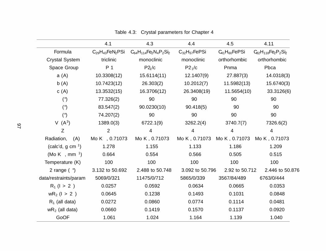
Table 4.3: Crystal parameters for Chapter 4
4.1 4.3 4.4 4.5 4.11
Formula C29H43FeN2PSi C64H114Fe2N4P2Si2 C32H57FePSi C41H60FePSi C82H118Fe2P2Si2
Crystal System triclinic monoclinic monoclinic orthorhombic orthorhombic
Space Group P−1 P21/c P21/c Pnma Pbca
a (A) 10.3308(12) 15.6114(11) 12.1407(9) 27.887(3) 14.0318(3)
b (A) 10.7423(12) 26.303(2) 10.2012(7) 11.5982(13) 15.6740(3)
c (A) 13.3532(15) 16.3706(12) 26.3408(19) 11.5654(10) 33.3126(6)
α (°) 77.326(2) 90 90 90 90
β (°) 83.547(2) 90.0230(10) 90.418(5) 90 90
γ (°) 74.207(2) 90 90 90 90
V (A3) 1389.0(3) 6722.1(9) 3262.2(4) 3740.7(7) 7326.6(2)
Z 2 4 4 4 4
Radiation, λ (A) Mo Kα, 0.71073 Mo Kα, 0.71073 Mo Kα, 0.71073 Mo Kα, 0.71073 Mo Kα, 0.71073
ρ (calc’d, g cm−1) 1.278 1.155 1.133 1.186 1.209
µ (Mo Kα, mm−1) 0.664 0.554 0.566 0.505 0.515
Temperature (K) 100 100 100 100 100
2Θ range (°) 3.132 to 50.692 2.488 to 50.748 3.092 to 50.796 2.92 to 50.712 2.446 to 50.876
data/restraints/param 5069/0/321 11475/0/712 5865/0/339 3567/84/489 6763/0/444
R1 (I > 2σ) 0.0257 0.0592 0.0634 0.0665 0.0353
wR2 (I > 2σ) 0.0645 0.1238 0.1493 0.1031 0.0848
R1 (all data) 0.0272 0.0860 0.0774 0.1114 0.0481
wR2 (all data) 0.0660 0.1419 0.1570 0.1137 0.0920
GoOF 1.061 1.024 1.164 1.139 1.040
97

4.9 References
[1] Hatanaka, T.; Ohki, Y.; Tatsumi, K. Synthesis of coordinatively unsaturated half–sandwich iron–silyl complexes with an N–heterocyclic carbene ligand and their reactionswith H2. Eur. J. Inorg. Chem. 2013, 3966–3971.
[2] Liu, Y.; Xiao, J.; Wang, L.; Song, Y.; Deng, L. Carbon-carbon bond formation reactivityof a four-coordinate NHC–supported iron(II) phenyl compound. Organometallics 2015,34, 599–605.
[3] Hayes, P. G.; Waterman, R.; Glaser, P. B.; Tilley, T. D. Synthesis, structure, andreactivity of neutral hydrogen-substituted ruthenium silylene and germylene complexes.Organometallics 2009, 28, 5082–5089.
[4] Tobita, H.; Mutsuda, A.; Hashimoto, H.; Ueno, K.; Ogino, H. Direct Evidence forExtremely Facile 1,2– and 1,3–Group Migrations in an FeSi2 System. Angew. Chem.Int. Ed. 2003, 43, 221–224.
[5] Lemon, C. M.; Huynh, M.; Maher, A. G.; Anderson, B. L.; Bloch, E. D.; Powers, D. C.;Nocera, D. G. Electronic structure of copper corroles. Angew. Chem. Int. Ed. 2016, 55,2176–2180.
[6] Guennic, B. L.; Floyd, T.; Galan, B. R.; Autschbach, J.; Keister, J. B. Paramag-netic effects on the NMR spectra of “diamagnetic” ruthenium (bis–phosphine)(bis–semiquinone) complexes. Inorg. Chem. 2009, 48, 5504–5511.
[7] Radon, M.; Radon, M. Revisiting the Role of Exact Exchange in DFT Spin–StateEnergetics of Transition Metal Complexes. Phys. Chem. Chem. Phys. 2014, 16, 14479–14488.
[8] Schrock, R. R.; Shih, K.-y.; Dobbs, D. A.; Davis, W. M. α–Elimination Can Be Fasterthan β–Elimination in d2 Alkyl Complexes of Molybdenum and Tungsten That Containthe Trimethylsilyl–Substituted Triamidoamine Ligand. J. Am. Chem. Soc. 1995, 117,6609–6610.
[9] Schrock, R. R.; Seidel, S. W.; Mosch-Zanetti, N. C.; Shih, K. Y.; O’Donoghue, M. B.;Davis, W. M.; Reiff, W. M. Synthesis and decomposition of alkyl complexes ofmolybdenum(IV) that contain a [(Me3SiNCH2CH2)3N]3
– ligand. Direct detection ofα–elimination processes that are more than six orders of magnitude faster than β–elimination processes. J. Am. Chem. Soc. 1997, 119, 11876–11893.
[10] Bellows, S. M.; Cundari, T. R.; Holland, P. L. Spin Crossover during β–Hydride Elimi-nation in High-Spin Iron(II)– and Cobalt(II)–Alkyl Complexes. Organometallics 2013,32, 4741–4751.
[11] Smith, P. W.; Tilley, T. D. Silane–Allyl Coupling Reactions of Cp∗(iPr2MeP)Fe(η3−allyl) and Synthetic Access to the Hydrido–Dinitrogen Complex Cp∗(iPr2MeP)FeH(N2).Organometallics 2015, 34, 2134–2138.
98

[12] Hickey, A. K.; Munoz, S. B.; Lutz, S. A.; Pink, M.; Chen, C.-H.; Smith, J. M. Arrestedα–hydride migration activates a phosphido ligand for C—H insertion. Chem. Commun.2017, 53, 412–415.
[13] Threlkel, R. S.; Bercaw, J. E.; Seidler, P. F.; Stryker, J. M.; Bergman, R. G. 1,2,3,4,5–Pentamethylcyclopentadiene. Org. Synth. 1987, 65, 42.
[14] Betley, T. A.; Peters, J. C. The strong-field tripodal phosphine donor, [PhB(CH2-PiPr2)3]– , provides access to electronically and coordinatively unsaturated transitionmetal complexes. Inorg. Chem. 2003, 42, 5074–5084.
[15] Simons, R. S.; Haubrich, S. T.; Mork, B. V.; Niemeyer, M.; Power, P. P. Thesyntheses and characterization of the bulky terphenyl silanes and chlorosilanes 2,6–Mes2C6H3SiCl3, 2,6–ceTrip2C6H3SiCl3, 2,6–Mes2C6H3SiHCl2, 2,6–Trip2C6H3SiHCl2,2,6–Mes2C6H3SiH3, 2,6–Trip2C6H3SiH3 and 2,6–Mes2C6. Main Gr. Chem. 1998, 2, 275–283.
[16] Glaser, P. B.; Tilley, T. D. Catalytic Hydrosilylation of Alkenes by a Ruthenium SilyleneComplex. Evidence for a New Hydrosilylation Mechanism. J. Am. Chem. Soc. 2003,125, 13640–13641.
[17] Battino, R.; Rettich, T. R.; Tominaga, T. The Solubility of Nitrogen and Air in Liquids.J. Phys. Chem. Ref. Data 1984, 13, 563–600.
[18] Bain, A. D.; Cramer, J. A. Slow chemical exchange in an eight–coordinated bicenteredruthenium complex studied by one–dimensional methods. Data fitting and error analy-sis. J. Magn. Reson. - Ser. A 1996, 118, 21–27.
[19] Bain, A. D.; Fletcher, D. A. Selective–inversion experiments applied to chemical ex-change in coupled spin systems. Mol. Phys. 1998, 95, 1091–1098.
[20] Shao, Y. et al. Advances in molecular quantum chemistry contained in the Q–Chem 4program package. Mol. Phys. 2015, 113, 184–215.
[21] Weigend, F.; Ahlrichs, R. Balanced basis sets of split valence, triple zeta valence andquadruple zeta valence quality for H to Rn: Design and assessment of accuracy. Phys.Chem. Chem. Phys. 2005, 7, 3297.
[22] Lin, Y. S.; Li, G. D.; Mao, S. P.; Chai, J. D. Long–range corrected hybrid densityfunctionals with improved dispersion corrections. J. Chem. Theory Comput. 2013, 9,263–272.
[23] Grimme, S. Semiempirical GGA–Type Density Functional Constructed with a Long–Range Dispersion Correction. J. Comput. Chem. 2009, 27, 1787–1799.
99

100
Chapter 5
Efficient and Selective Fe Hydrosilation Catalysis via
Concerted Double Si—H Activation
5.1 Introduction
Olefin hydrosilation is one of the most commercially important reactions, used to producevarious silicon–containing materials and fine chemicals.1,2 This reaction mainly employs Pt–based catalysts3,4 which, given the limited supply and high demand for platinum, creates astrong motivation for development of alternative catalysts based on more earth–abundantmetals such as Fe, Co, and Ni.5–18 There are profound differences between the chemicalproperties of Pt and those of the base metals; most notably the lighter 3d metals have ahigher propensity for one–electron reaction steps, which may preclude the oxidative addi-tion/reductive elimination cycles associated with noble metal catalysis. For this reason, thesearch for base metal hydrosilation catalysts must include discovery of alternative mechanis-tic pathways suitable for the 3d metals.19
Previous work in this laboratory identified a new mechanism for hydrosilation20,21 asso-ciated with cationic silylene complexes of Ru20,22 and Ir.23,24 Unique to this mechanism isthe Si—C bond forming step, in which a Si—H bond in a silylene ligand directly adds acrossthe olefin.25,26 This process is attractive for the design of new hydrosilation catalysts basedon 3d metals such as Fe, as this critical bond formation does not rely on a metal-centeredredox process. Hydrosilation reactions catalyzed by cationic silylene complexes form sec-ondary silane products with linear regioselectivity for the Si—H addition. This selectivityrepresents an advantage over the more conventional Chalk–Harrod mechanism, which canresult in a mixture of linear and branched products due to its reliance on reversible olefininsertion into a metal hydride.
Another unique aspect of this silylene–based mechanism is the double Si—H bond acti-vation that occurs at the metal center,21,27 as discussed in . Double Si—H activations of thistype occur to varying degrees, from moderate activation to give η3–silane complexes,27–30
to more strongly activated cases that have undergone a double oxidative addition to forma silylene dihydride.22,31–33 Structures along this continuum exhibit high electrophilicity atsilicon and greater reactivity for the terminal Si—H bond.
Since the silylene-based mechanism is well established for Ru complexes of the type[Cp∗(iPr3P)Ru(H)2SiHR]+, catalytic transformations with analogous Fe complexes couldprovide increased activity due to the enhanced lability of metal-ligand bonds in 3d complexes.This chapter describes Cp∗(iPr2MeP)FeH(N2)34 (2.6) as a precatalyst for hydrosilation via
101

generation of a cationic Fe intermediate. This Fe system is associated with higher rates ofconversion for many substrates, and a marked selectivity toward terminal olefins that wasnot observed for Ru.
5.2 Catalytic Conditions and Substrate Scope
Precursors to the catalytic species of interest are neutral Fe complexes of the type Cp∗-(iPr2MeP)Fe(H)2SiH2R. Compound 2.6 reacts with primary silanes (RSiH3, R = Trip,Ph, p–Tol, Mes) by oxidative addition of the Si—H bond to form the corresponding dihy-drides Cp∗(iPr2MeP)Fe(H)2SiH2R (R = Ph, 5.1a; R = Mes, 5.1b; R = p–Tol, 5.1c; R =Trip, 4.9;35 eq 5.1). Note that related half-sandwich complexes have been reported previ-ously.34,36,37 These silyl dihydride complexes do not promote hydrosilations up to 80 °C, butthey are converted to active cationic catalysts by hydride abstraction.
Fe
P SiH2
R
H H
Fe
PN2
H
RSiH3
Pentane−N2
R = PhR = MesR = p−Tol
PSfrag replacements
2.65.1a
5.1b
5.1c
(5.1)
Catalyst activation with Ph3CBArF4 The putative cationic complex Cp∗(iPr2-
MeP)FeH2SiHPh)][BArF4 ] (5.2a, vide infra) was generated by treatment of 2.6 with 1000
equiv of PhSiH3 followed by 1 equiv [Ph3C][BArF4 ] in fluorobenzene at −35 °C. After warm-
ing to ambient temperature, treatment with 1100 equiv of 1–octene resulted in quantitativeconversion to the linear product, Ph(nOct)SiH2, over 6 h (eq 5.2) corresponding to a turnoverfrequency (TOF) of ca. 170 h−1. This selectivity is consistent with the cationic silylene hy-drosilation mechanism of Figure 1.14.20,22,25,26 For this reaction the Fe catalyst is more activethan the Ru analogue, which required a higher loading (1 mol %) and elevated temperature(80 °C) to achieve a comparable conversion.22 This activity is in the range of the most activeFe catalysts for the hydrosilation of olefins by primary silanes (Table 5.1).10,18,38–40
1. 0.1 %2. 0.1 % [Ph3C][BArF
4]3.
fluorobenzenePhSiH3
C6H13
C6H13
PhH2SiPSfrag replacements
2.6
(5.2)
102

Table 5.1: Comparison of reported Fe catalysts for hydrosilation of 1–octene by PhSiH3 toproduce the anti–Markovnikov product.
entry catalyst loading (mol %) time (h) yield (%)
1 2.6 + Ph3CBArF4 0.1 6 > 99 %
218 (pyridyldiimine)Fe(N2)2 0.3 1 98 %a
338(R2P(CH2)–pyridyldiimine)FeCl2 1
3 50–98b
NaBHEt3 2
441(oxazolinepyridylimine)FeCl2 5
2 2–77bcd
NaOtBu 15
539(pyridyldiimine)Fe(OTf)2 2
1 95biPr2EtN 25
640(R2P–O–pyridylimine)FeCl2 1
3 0–99b
NaBHEt3 2
aNo 1–octene data presented; substrate was 1-hexene.bRange of reported catalystscNo 1–octene data presented; substrate was 5–methyl–1–pentene.dCatalyst optimized for the Markovnikov product.
Substrate scope. Aryl– and alkyl–substituted primary silanes are suitable sub-strates for this catalysis (Table 5.2), but steric factors play an important role. While (o–ethylphenyl)silane is a competent substrate, hydrosilation of 4–methylpentene with mesityl-silane did not proceed even at 80 °C. No hydrosilation products were observed with secondaryor tertiary silanes (e.g. PhMeSiH2 and Et3SiH) up to 1 % catalyst loading over 20 h at am-bient temperature. Unlike the Ru analogues, the Fe catalysts have only shown hydrosilationreactivity with terminal olefins (Table 5.3). This difference in substrate tolerance may arisefrom the size difference between Ru and Fe, resulting in greater steric demands from the Feancillary ligands in the hydrosilation transition state, and is most dramatically illustratedby the hydrosilation of limonene (entry 5.3k) which resulted in complete selectivity for theterminal double bond.
The Fe catalysts are selective for hydrosilation of internal alkyne substrates with noconversion observed for terminal alkynes (entries 5.3l–o, Table 5.3). Exclusive cis–hyd-rosilation was observed by 1H NMR spectroscopy, consistent with direct Si—H addition.Entry 5.3m further suggests that the catalyst selectivity is driven by steric factors, sincepropynyltrimethylsilane was hydrosilated to form 2–phenylsilyl–1–trimethylsilylpropene withnearly 90 % selectivity. The intolerance for terminal acetylenic substrates is most likely dueto side reactions with the acetylenic C—H bond.
The selectivity of this catalyst system suggested the use of SiH4 to form secondary silanes(eq 3). For this reaction, the catalyst was generated by reaction of 5.1b with [Ph3C][BArF
4 ]in fluorobenzene to form [Cp∗(iPr2MeP)FeH2SiHMes]+ (5.2b), which was then treated with
103

Table 5.2: Silane scope for hydrosilation of 4–methylpentene. Conditions: fluorobenzene,0.1 mol % loading, ambient temperature.
silane product time (h) yielda
5.3a PhSiH3 PhH2Si(CH2)2CHMe2 6 > 99
5.3b p–TolSiH3 (p–Tol)H2Si(CH2)2CHMe2 20 > 99
5.3c 2–Et–PhSiH3 (2–Et–Ph)H2Si(CH2)2CHMe2 20 > 99
5.3d MesSiH3 MesH2Si(CH2)2CHMe2 20 0b
5.3e NorSiH3 NorH2Si(CH2)2CHMe2 20 > 99
aisolated yieldbsilane redistribution observed at 80 °C.
Table 5.3: Olefin and alkyne scope for hydrosilation of PhSiH3. Conditions: fluorobenzene,0.1 mol % loading, ambient temperature.
alkene/alkyne product time (h) yielda
5.3f 1–octene PhH2Si(C8H17) 6 > 99
5.3g tBuCH––CH2 PhH2Si(CH2)2CMe3 0.5 95 (97)
5.3h styrene PhH2Si(CH2)2Ph 20 97 (98)
5.3i (E )–3–hexene PhH2SiCH(C2H5)C3H7 20 0b
5.3j cyclohexene PhH2SiCy 20 0
5.3k limoneneH2Si
Ph 20 92 (97)c
5.3l 3–hexyne PhH2SiC(Me)––CHMe 5 87 (95)
5.3m propynyltrimethylsilanePhH2Si
R
R' 20 89 (97)d
5.3n diphenylethyne PhH2SiC(Ph)––CHPh 20 0
5.3o iPrC2H PhH2SiC(H)––CHPh 20 0
aisolated yield (NMR yield)btrace silane redistribution observed at ambient temperaturecdiastereomeric excess = 15 %.dR = Me, R = SiMe3, 87.5 %; R = SiMe3, R = Me, 12.5 %.
104

400 equiv of 4–methylpentene and exposed to 1 atm of 15 % SiH4 in nitrogen. While theyield of (4–Me–pentyl)2SiH2 was only 2.6 % (based on olefin; TON = 52), the reaction ishighly selective in that only the secondary silane was observed as product (by 1H NMRspectroscopy and TLC). The low yield is attributed to the concentration of SiH4; higherpressures of silane would likely give greater turnover.
SiH4 +fluorobenzene
H2Si
2PSfrag replacements
5.2b(5.3)
5.3 Characterization of the Cationic Fe Catalysts
Attempts to isolate the activated catalysts were not successful; in all cases, crystallizationattempts produced impure oils, prompting characterization in situ by NMR spectroscopy.Compound 5.1c was treated with 1 equiv of [Ph3C][BArF
4 ] at −35 °C in fluorobenzene inan attempt to generate Cp∗(iPr2MeP)FeH2SiH(p –Tol)]+ (5.2c, eq 5.4), which resulted ina color change to blue. Integration against a C6Me6 internal standard indicated that 5.2cwas formed in > 99 % yield. The 1H NMR spectrum at room temperature did not containobvious Fe—H—Si or Si—H resonances, suggesting exchange between these positions. Uponcooling a solution of 5.2c in fluorobenzene–d5 to −30 °C, Fe—H (−15.12 ppm, J PH = 20.9Hz, J SiH = 90 Hz) and Si—H (6.74 ppm, J SiH = 180 Hz) resonances were observed. Theseresonances display cross peaks to a downfield 29Si resonance at 188 ppm in the 1H–29SiHMBC spectrum. The moderate value of the J Fe–H–Si coupling constant (90 Hz) indicatesSi—H bond activation that is somewhat less than that for the Ru system (J = 63 Hz).
Fe
P SiH2H H
RSiH3
Pentane−N2
Fe
PSiH
H
HPSfrag replacements
5.1c 5.2c (5.4)
Computations of the electronic structure of 5.2a (Figure 5.1) at the B3LYP–D3–PCM/6–311G∗∗-LANL2TZ(f) level of theory are indicate Si—H activation at Fe is modest. The ge-ometry of the molecule is consistent with an η3-silane structure, with hydrides symmetricallybridging the Fe and Si atoms (dFeSi = 2.22 A). The Si—H(bridge) distances are longer thanthe terminal Si—H distance (1.59 vs. 1.48 A) and the Fe—H distances are both 1.69 A.The FeH2Si unit is planar (Σ6 = 359°). Various orbital localization methods indicate thatthe interaction is a double Si—H σ donation to the metal center without any direct Fe—Si
105
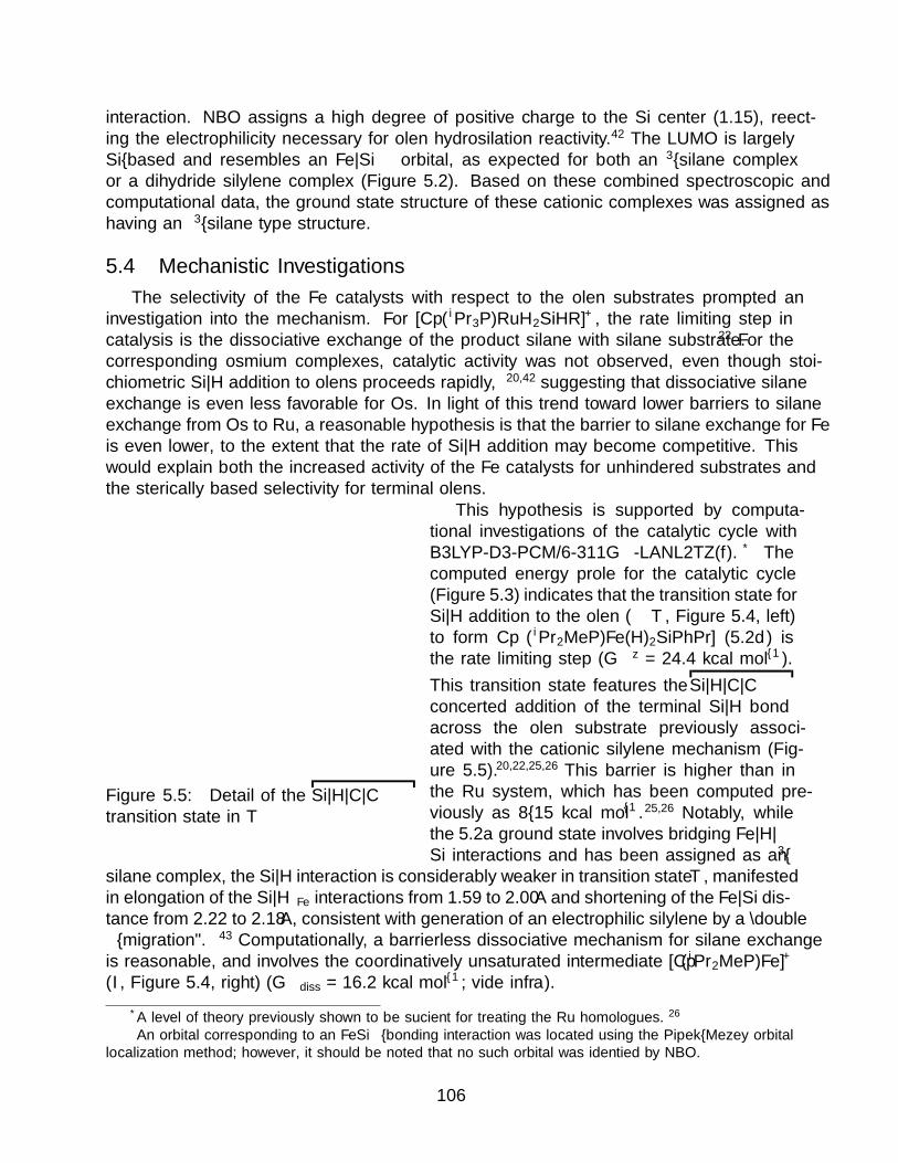
interaction. NBO assigns a high degree of positive charge to the Si center (1.15), reflect-ing the electrophilicity necessary for olefin hydrosilation reactivity.42 The LUMO is largelySi–based and resembles an Fe—Si π∗ orbital, as expected for both an η3–silane complexor a dihydride silylene complex (Figure 5.2). Based on these combined spectroscopic andcomputational data, the ground state structure of these cationic complexes was assigned ashaving an η3–silane type structure.
5.4 Mechanistic Investigations
The selectivity of the Fe catalysts with respect to the olefin substrates prompted aninvestigation into the mechanism. For [Cp∗(iPr3P)RuH2SiHR]+, the rate limiting step incatalysis is the dissociative exchange of the product silane with silane substrate.22 For thecorresponding osmium complexes, catalytic activity was not observed, even though stoi-chiometric Si—H addition to olefins proceeds rapidly,20,42 suggesting that dissociative silaneexchange is even less favorable for Os. In light of this trend toward lower barriers to silaneexchange from Os to Ru, a reasonable hypothesis is that the barrier to silane exchange for Feis even lower, to the extent that the rate of Si—H addition may become competitive. Thiswould explain both the increased activity of the Fe catalysts for unhindered substrates andthe sterically based selectivity for terminal olefins.
Figure 5.5: Detail of the Si—H—C—Ctransition state in T
This hypothesis is supported by computa-tional investigations of the catalytic cycle withB3LYP-D3-PCM/6-311G∗∗-LANL2TZ(f).* Thecomputed energy profile for the catalytic cycle(Figure 5.3) indicates that the transition state forSi—H addition to the olefin (T, Figure 5.4, left)to form Cp∗(iPr2MeP)Fe(H)2SiPhPr] (5.2d) isthe rate limiting step (∆G‡ = 24.4 kcal mol–1).
This transition state features the Si—H—C—Cconcerted addition of the terminal Si—H bondacross the olefin substrate previously associ-ated with the cationic silylene mechanism (Fig-ure 5.5).20,22,25,26 This barrier is higher than inthe Ru system, which has been computed pre-viously as 8–15 kcal mol–1.25,26 Notably, whilethe 5.2a ground state involves bridging Fe—H—Si interactions and has been assigned as an η3–
silane complex, the Si—H interaction is considerably weaker in transition state T, manifestedin elongation of the Si—HFe interactions from 1.59 to 2.00 A and shortening of the Fe—Si dis-tance from 2.22 to 2.18 A, consistent with generation of an electrophilic silylene by a “doubleα–migration”.� 43 Computationally, a barrierless dissociative mechanism for silane exchangeis reasonable, and involves the coordinatively unsaturated intermediate [Cp∗(iPr2MeP)Fe]+
(I, Figure 5.4, right) (∆Gdiss = 16.2 kcal mol–1; vide infra).
*A level of theory previously shown to be sufficient for treating the Ru homologues.26�An orbital corresponding to an FeSi σ–bonding interaction was located using the Pipek–Mezey orbital
localization method; however, it should be noted that no such orbital was identified by NBO.
106

Figure 5.1: Structure of 5.2a computed at the B3LYP–D3–PCM/6–311G∗∗-LANL2TZ(f)level of theory
Figure 5.2: Calculated HOMO (left) and LUMO (right) for 5.2a at the PCM–B3LYP/6-311G∗∗–LANL2TZ(f) level of theory.
107

0.0
24.4
-12.3
3.9
-12.8
+ C3H6
+ PhSiH3
T + PhSiH3
+ PhSiH3 + PrPhSiH2
I + PhSiH3 + PrPhSiH2
Fe
PSi
PhH
H
H
Fe
PSi
PhH
H
Fe
P SiPh
H H
H
Fe
P
I
T
H
PhH2Si
H
RSiH3
PSfrag replacements
5.2a
5.2a
5.2a
5.2d
5.2d
Figure 5.3: Top: Calculated catalytic cycle for hydrosilation catalyzed by 5.2a. Colorcoding tracks the fate of the silane (red) and propylene (blue) substrates; bonds in thetransition state are colored by the nucleophilic partner of a forming bond. Bottom: Solvatedfree energies of intermediates along the hydrosilation catalytic cycle. Energies were calculatedat the PCM–B3LYP/6-311G∗∗–LANL2TZ(f) level of theory.
108

Figure 5.4: DFT calculated structure at the PCM–B3LYP/6-311G∗∗–LANL2TZ(f) levelof theory for the transition state of olefin hydrosilation T (left) and the coordinativelyunsaturated intermediate I (right).
Figure 5.6: Eyring plot of the exchange of p–TolSiH3 with 5.2c.
109

Figure 5.7: Broadening and coalescence behavior of the aryl methyl region and SiH3 reso-nance of the exchange of p–TolSiH3 with 5.2c.
110

A dissociative mechanism for silane exchange is further supported by VT NMR spec-troscopy. The complex Cp∗(iPr2MeP)FeH2SiH(p –Tol)][BArF
4 ] (5.2c) was generated in fluo-robenzene solution, in the presence of 1 equiv of p–tolylsilane. The tolyl CH3 and free SiH3
resonances were monitored from 235 to 330 K (Figure 5.7). Rate constants for the exchangebetween p–tolylsilane and 5.2c were determined based on lineshape analysis; an Eyring plot(Figure 5.6) gave the activation parameters ∆H‡ = 24(2) kcal mol–1 and ∆S‡ = 24(6) calmol-1 K-1 (∆G‡295 = 17(2) kcal mol–1). These parameters are consistent with a dissociativeexchange mechanism similar to that proposed for the Ru system (∆H‡ = 32(2) kcal mol–1
and ∆S‡ = 19(1) cal mol-1 K-1, ∆G‡295 = 26(2) kcal mol–1),22 with the lower enthalpy ofactivation for Fe reflecting weaker bonding of the ligand to the metal and less activatedSi—H bonds in the Fe system (relative to Ru).
The computed pathway for dissociation of silane via cleavage of the Si—H···Fe interactionscould in principle be concerted or stepwise. However, computations at the B3LYP/6-311G∗∗-LANL2TZ(f) level of theory did not identify a stationary point for an initial dissociation ofjust one Si—H bond from the metal. To investigate whether this was a failure of DFT toproperly locate a minimum along a flat potential surface, relaxed potential energy surfacescans were performed along the Fe—Si coordinate (the reaction coordinate for dissociationof silane from the metal center). These scans suggest that there is not an energetic minimumalong this coordinate for either the PhnPrSiH2 or PhSiH3 dissociation (Figure 5.8). However,the potential energy surface flattens at Fe—Si distances of ca. 3 A, corresponding to an initialdissociation of an Si—H unit (Figure 5.9; this is more pronounced in the energy curve for thePhnPrSiH2 dissociation than for PhSiH3). These intermediate geometries feature a nearlylinear Fe—H—Si interaction corresponding to a silane σ–complex, a structural motif thathas some precedent.10 However, they do not correspond to a stationary point along thePES; thus, while the dissociation can be thought of as stepwise there is no true intermediateformed.
Figure 5.8: PES scans for dissociation of phenylsilane (left, red) and n–propylsilane (right,blue) from [Cp∗(iPr2MeP)Fe]+.
5.5 Conclusion
The cationic Fe catalysts described here are highly active in the hydrosilation of unhin-dered olefins with primary silanes. This discovery provides a basis for new catalyst design
111

Figure 5.9: Relaxed geometry of 5.2a with an Fe—Si distance constrained to 3.2 A. TheFe—H—Si angle is 151°; dFeH = 1.76 A; dSiH = 1.54 A
112

strategies involving the first-row transition metals. Importantly, the mechanism for thiscatalysis is non–oxidative in character, in that distinct oxidative additions are not required.The observed rate accelerations relative to the homologous Ru system appear to be a con-sequence of weaker metal–silane binding, which leads to a faster dissociative exchange ofthe product silane for the silane substrate. Furthermore, the Fe system is different in thatthe rate-determining step is addition of the Si—H bond across the olefin, leading to muchhigher selectivities for the olefinic substrate. The increase in both rates and product selec-tivity, in addition to the lower cost and greater sustainability of Fe relative to Ru, makes thepresent system highly attractive for the synthesis of unsymmetrical secondary silanes, andmultiply–substituted silicon centers derived therefrom.
5.6 Experimental Section
General Considerations. All manipulations were carried out using standard Schl-enk or inert atmosphere glovebox techniques with an atmosphere of dry dinitrogen. Pen-tane was dried over activated alumina and stored over molecular sieves (4 A) prior to use.Benzene–d 6 was degassed with 3 freeze–pump–thaw cycles and stored over activated molec-ular sieves (4 A) for 24 h prior to use. Fluorobenzene was purchased from Sigma Aldrich,dried by distillation from calcium hydride, and stored over molecular sieves. 3–Hexyne,4-methyl–1–pentene, R–(+)–limonene, styrene, methylenecyclopentane, 3, 3–dimethyl–1–butene and 1–octene were purchased from Sigma–Aldrich. Phenylsilane was purchased fromOakwood Chemicals. p–tolylsilane was purchased from Gelest. All liquid reagents were sub-jected to three freeze–pump–thaw cycles and stored over activated molecular sieves overnight.The preparations and characterization of Cp∗(iPr2MeP)FeH(N2)34 (2.6) and Cp∗(iPr2MeP-)H2FeSiH2Trip35 have been described previously. NMR spectra were recorded using BrukerAvance 400, 500, or 600 MHz spectrometers equipped with a 5 mm broad band or TBIprobe. Spectra were recorded at room temperature (ca. 22 °C) and referenced to the resid-ual protoisotopomer of the solvent for 1H unless otherwise noted. 31P{1H} NMR spectrawere referenced relative to 85 % H3PO4 external standard (δ = 0). 13C{1H} NMR spectrawere calibrated internally with the resonance for the solvent relative to tetramethylsilane.For 13C{1H} NMR spectra, resonances obscured by the solvent signal were omitted. 29SiNMR spectra were obtained via 2D 1H 29Si HMBC. Elemental analyses were performedby the College of Chemistry Microanalytical Laboratory at the University of California,Berkeley.
General synthesis of Cp∗(iPr2MeP)H2FeSiH2R (5.1). RSiH3 (0.284 mmol) was
dissolved in 2 mL of pentane and this solution was then added to Cp∗(iPr2MeP)FeH(N2)(0.100 g, 0.284 mmol) in 4 mL of pentane. The resulting mixture was stirred for 18 h, overwhich time the color changed from orange to yellow. Volatile components were removed invacuo and the resulting yellow solid was recrystallized from 2 mL 1:1 pentane/(SiMe3)2O.
Characterization data for 5.1a. 1H NMR (400 MHz, benzene–d 6) δ 8.26 – 8.18(m, 2H, PhH ), 7.40 (td, J = 7.1, 6.4 2H, PhH ), 7.31 – 7.26 (m, 1H, p–PhH ), 5.22 (s, J SiH
= 179 Hz, 2H, SiH ), 1.65 (s, 15H, Cp∗), 1.58 – 1.41 (m, 3H, PCH Me2), 1.05 – 0.91 (m, 9H,PCHCH 3 + PCH 3), 0.83 (dd, J = 13.1, 6.8 Hz, 6H, PCHCH 3), −14.20 (d, J = 54.4 Hz,2H, FeH ). 13C{1H} NMR (101 MHz, benzene–d 6) δ 144.50, 136.17, 127.63, 87.41, 29.11 (d,J = 26.0 Hz), 17.98 (d, J = 2.4 Hz), 17.09, 11.12, 7.11 (d, J = 12.2 Hz). 31P{1H} NMR
113
(162 MHz, benzene–d 6) δ 76.52. 29Si NMR (79 MHz, HMBC, benzene–d 6) δ -7.5 (J SiH = 11[8.22 ppm], 178 [5.22 ppm], 16 [−14.20 ppm] Hz). Anal Calcd. for C23H41FePSi: C, 63.88;H, 9.56. Found: C, 63.60; H, 9.35.
Characterization data for (5.1b). 1H NMR (400 MHz, benzene–d 6) δ 8.14 (d, J= 7.5 Hz, 2H, p–TolH ), 7.23 (d, J = 7.5 Hz, 2H, p–TolH ), 5.23 (s, J SiH = 178 Hz, 2H,SiH ), 2.24 (s, 3H p–TolCH 3), 1.68 (s, 15H, Cp∗), 1.51 (hept, J = 7.1 Hz, 3H, PCH Me2),1.05–0.93 (m, 9H, PCHCH3 + PCH3), 0.84 (dd, J = 13.1, 6.8 Hz, 6H, PCHCH 3), -14.18(d, J = 54.3 Hz, 2H, FeH ). 13C{1H} NMR (101 MHz, benzene–d 6) δ 140.68, 137.05, 136.32,128.51, 87.36, 29.12 (d, J = 26.0 Hz), 21.51, 17.99 (d, J = 2.4 Hz), 17.10, 11.16, 7.13 (d, J= 12.0 Hz). 31P{1H} NMR (162 MHz, benzene–d 6) δ 76.67. 29Si NMR (79 MHz, HMBC,benzene–d 6) δ -6.7 (J SiH = 12 [8.14 ppm], 179 [5.23 ppm], 16 [-14.18 ppm] Hz). Anal Calcd.for C24H43FePSi: C, 64.56; H, 9.71. Found: C, 64.39; H, 9.53.
Characterization data for (5.1c). 1H NMR (400 MHz, benzene–d 6) δ 6.79 (s, 2H,MesH ), 5.20 (d, J = 5.9 Hz, 2H, SiH ), 2.78 (s, 6H, o–MesCH 3), 2.17 (s, 3H, p–MesCH 3),1.75 (s, 15H, Cp∗), 1.28 (d, J = 6.9 Hz, 3H, PCH Me2), 0.90 (dd, J = 14.6, 7.0 Hz, 6H,PCHCH 3), 0.74 (dd, J = 12.3, 6.9 Hz, 6H, PCHCH 3), 0.39 (d, J = 7.5 Hz, 3H, PCH 3),−15.01 (dd, J = 55.9, 5.9 Hz, 2H, FeH ). 13C{1H} NMR (101 MHz, benzene–d 6) δ 144.56,138.40, 136.97, 128.51, 87.06, 28.28 (d, J = 21.9 Hz), 23.05, 21.30, 19.04 (d, J = 3.1 Hz),17.65 (d, J = 2.4 Hz), 10.79, 8.78 (d, J = 20.0 Hz). 31P{1H} NMR (162 MHz, benzene–d 6)δ 77.45. Anal Calcd. for C24H43FePSi: C, 65.80; H, 9.98. Found: C, 66.09; H, 9.77.
General Procedure for Hydrosilation Catalysis. Stock solution A was preparedby dissolving 2.6 (10 mg, 0.028 mmol) in 5.0 ml of PhF. Stock solution B was prepared bydissolving [Ph3C][BArF
4 ] (26 mg, 0.028 mmol) in 2.5 ml of PhF. Both were stored at -30 oC,and used at that temperature. After cooling the desired silane (1.4 mmol) in a J. YoungNMR tube to −30 °C, 0.2 ml of stock solution A was added, followed by 0.1 ml of stocksolution B and finally the olefin or alkyne (2.1 mmol) was added. The reaction progress wasmonitored by NMR spectroscopy and quenched with wet diethyl ether after completion. Theproduct was purified by passing the reaction mixture through an alumina plug and driedunder vacuum overnight. Characterization data for each product is given in 5.8
Hydrosilation of 4–methylpentene with SiH4 to form bis(4–methylpentyl)sil-ane. A solution of 5.1b (0.0020 g, 4.2 mol) in 0.5 mL of PhF was cooled to -35 C andtreated with [Ph3C][BArF
4 ] (0.0039 g, 4.2 mol) in 0.5 mL of PhF. 4-Methylpentene (0.140g, 1.66 mmol) was added to the resulting blue-green solution, after which it became red.The solution was transferred to a PTFE–stoppered flask, the solution was frozen with liquidnitrogen, and the headspace was evacuated and backfilled with 15 % silane in nitrogen. Thesolution was allowed to warm to ambient temperature over 1 h after which the flask was sealedand the solution was stirred for 18 h. At this point, 4 mL of diethyl ether was added andthe resulting solution was filtered through alumina and volatile components were removed invacuo to give a colorless oil. While at this point the predominant component of the isolatewas bis(4-methylpentyl)silane, further purification was achieved by column chromatography(silica with hexanes). Yield: 0.022 g, 2.6 %. 1H NMR (500 MHz, benzene–d 6) δ 3.97 (p, J= 3.7 Hz, J SiH = 183 Hz, 2H), 1.50 (hept, J = 6.7 Hz, 2H), 1.45–1.37 (m, 4H), 1.25–1.17(m, 4H), 0.88 (d, J = 6.6 Hz, 12H), 0.63 (dq, J = 11.6, 3.6 Hz, 4H). 13C{1H} NMR (126MHz, benzene–d 6) δ 42.70, 28.07, 23.72, 22.78, 9.72. HRMS (EI, m/z): Calcd for C12H26Si:[M– 2H]+ 198.1804, found 198.1802.
114

In situ yield of 5.2c. Compound 5.1c (0.0167 g, 0.0374 mmol) and C6Me6 (0.0052g, 0.018 mmol) were dissolved in 0.5 mL of PhF. This solution was split into 2 equal portions(0.25 mL each); one was diluted to 0.5 mL and sealed in a J–Young tube to form the referencesample, while the other was cooled to −35 °C. [Ph3C][BArF
4 ] (0.0172 g, 0.0186 mmol) wasdissolved in 0.25 mL of PhF, and this solution was cooled to −35 °C before adding it to thecooled 5.1c solution, resulting in a color change to green. The resulting solution was allowedto warm to room temperature and was transferred to a J–Young tube for spectroscopicstudy. The yield of 5.2c, determined by relative integration of the reaction mixture vs. thereference sample, was > 99 %. 1H NMR (500 MHz, fluorobenzene, 295 K) δ 5.45 (s, 1H,Ph3CH ), 2.20 (s, 3H, p–TolCH 3), 2.11 (s, C6Me6), 1.39 (s, 15H, Cp∗), 1.43–1.20 (mult, 5H,PCH 3 and PCH Me2) 0.81 (dd, J = 13.9, 6.8 Hz, 6H, PCH 3), 0.67 (dd, J = 15.7, 7.0 Hz,6H, PCH 3). 1H NMR (500 MHz, fluorobenzene, 235 K) δ 5.42 (s, 1H, Ph3CH ), 2.19 (s, 3H,p–TolCH 3), 2.11 (s, C6Me6), 1.37 — 1.16 (m, 20H, Cp∗ + PCH 3 + PCH Me2), 0.75 (dd, J= 14.1, 6.6 Hz, 6H, PCH 3), 0.62 (dd, J = 14.8, 7.6 Hz, 6H, PCH 3), -15.12 (d, J = 20.8 Hz,2H, Fe—H —Si). EXSY 31P{1H} NMR (202 MHz, fluorobenzene, 240 K) δ 54.04.
In situ characterization of 5.2c by VT NMR spectroscopy. Compound 5.1c(0.0086 g, 0.019 mmol) was dissolved in 0.25 mL of fluorobenzene–d5, and the resultingsolution was cooled to −35 °C. A separate solution of [Ph3C][BArF
4 ] (0.0172 g, 0.019 mmol)in 0.25 mL fluorobenzene–d5 was also cooled to −35 °C, and then added to the cooled 5.1csolution resulting in a color change to green. This solution was allowed to warm to roomtemperature and transferred to a J–Young tube for spectroscopic study. 1H NMR (295 K,500 MHz, fluorobenzene–d5) δ 7.41 (d, J = 7.9 Hz, 2H, p–TolH ), 7.19 (d, J = 7.7 Hz, 2H, p–TolH ), 7.17–7.09 (m, 8H, HCPh3H ), 5.45 (s, 1H, Ph3CH ), 2.20 (s, 3H, p–TolCH 3), 1.38 (s,18H, Cp∗ + PCH 3), 0.80 (dd, J = 14.0, 6.8 Hz, 6H, PCH 3), 0.67 (dd, J = 15.7, 7.0 Hz, 6H,PCH 3). 1H NMR (235 K, 500 MHz, fluorobenzene–d5) δ 7.44 (d, J = 7.5 Hz, 2H, p-TolH),7.19 (d, J = 7.7 Hz, 2H, p-TolH), 7.18 – 7.08 (m, 9H, HCPh3H), 6.74 (s, 1H, SiH ), 5.43 (s,1H, Ph3CH ),), 2.19 (s, 3H, p–TolCH 3), 1.34 (d, J = 8.6 Hz, 3H, PCH 3), 1.31 (s, 15H, Cp∗),1.12 (hept, J = 6.0 Hz, 3H, PCH Me2), 0.75 (dd, J = 14.0, 6.7 Hz, 6H, PCH 3), 0.62 (dd, J= 15.7, 6.9 Hz, 6H, PCH 3), −15.12 (d, J = 20.2 Hz, 2H, FeH ). 29Si NMR (79 MHz, HMBC,fluorobenzene–d5) δ 189 (J SiH = 238 Hz [6.74 ppm], 90 Hz [−15.12 ppm]). 13C{1H} NMR(126 MHz, fluorobenzene–d5) δ 144.57 (Ph3CH), 133.81 (p–Tol), 130.09 (Ph3CH), 128.89(Ph3CH), 126.87 (Ph3CH), 88.86 (Cp∗), 57.31 (Ph3C H), 34.73 (pentane), 29.04 (d, J = 25.3Hz, PCHMe2), 23.12 (pentane), 21.62, 17.49, 16.65, 14.47, 10.86 (Cp∗ Me), 5.56 (d, J = 21.4Hz, PMe).
115

Figure 5.10: 1H NMR spectrum of 5.2c at 235 K in fluorobenzene–d5. The doubletemerging from the Cp∗ resonance has slightly higher integration than expected (4 vs. 3),likely due to residual intensity of the large Cp∗ resonance.
116

Figure 5.11: 1H NMR spectrum of 5.2c at 289 K in fluorobenzene–d5.
117

Figure 5.12: Broadening of the Si—H and Fe—H—Si 1H resonances of 5.2c influorobenzene–d5 from 235–311 K (ca. 11 K increments). The high temperature coales-cence was not observed prior to thermal decomposition.
118

Exchange kinetics of 5.2c with p–TolSiH3. Compound 5.1c (0.0104 g, 23.3 µmol)
and [Ph3C][BArF4 ] (0.0390 g, 42.3 mol) were separately dissolved in 1.00 mL of PhF and the
resulting solutions were cooled to −35 °C. 0.18 mL of the trityl solution was added to 0.33 mLof the 5.1c solution at −35 °C and this mixture was allowed to warm to room temperature,forming a deep blue solution. A solution of p–TolSiH3 (0.0106 g, 86.7 µmol) in 1 mL of PhFwas prepared, 0.09 mL was added to the solution of 5.2c described above, and the mixturewas placed in a J–young tube for VT NMR spectroscopy. Exchange rates were determined byline–shape modeling using the text–based distribution of the MEXICO program by allowingthe rate constant to freely vary. The natural linewidth was determined by freely fitting thisvalue for the 290 K data, then correcting it for additional broadening by examination ofthe Ph3CH resonance. Treatment of the 321 K data was complicated by the presence of anadditional, minor resonance at 1.985 ppm (visible in other spectra) that obscured the shape ofthe broadened line underneath. To treat this, the data were first corrected by subtraction ofa Lorentzian function centered at 984 Hz and broadened by 7.34 Hz (the corrected naturallinewidth at this temperature); the intensity of this function was determined empirically(Figure 5.16). The exchange constants and plots of the fits at each temperature are givenin Table 5.4 and Figure 5.13–Figure 5.18. Fitting of the resulting k values was performedusing LINEST in Microsoft Excel to give the Eyring plot and activation parameters shownin Figure 5.6 and Table 5.4.
Table 5.4: Raw exchange data (left) and LINEST output (right) for the Eyring plot of theexchange of p–TolSiH3 with 5.2c
T k 1/T ln(k/T) Fit Error
289.756 2.3504 0.003451 −4.81445 slope −11903.3 915.5414
300.317 3.921 0.00333 −4.33849 intercept 35.72783 2.910066
310.878 16.911 0.003217 −2.91144 R2 0.976883
321.439 79.686 0.003111 −1.39471 ∆H‡ (kcal mol–1) 23.63843 1.818153
332 334.329 0.003012 0.006991 ∆S‡ (kcal mol–1 K-1) 23.76667 5.779035
342.561 1116.682 0.002919 1.1816
119
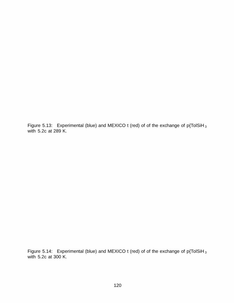
Figure 5.13: Experimental (blue) and MEXICO fit (red) of of the exchange of p–TolSiH3
with 5.2c at 289 K.
Figure 5.14: Experimental (blue) and MEXICO fit (red) of of the exchange of p–TolSiH3
with 5.2c at 300 K.
120

Figure 5.15: Experimental (blue) and MEXICO fit (red) of of the exchange of p–TolSiH3
with 5.2c at 311 K.
Figure 5.16: Solid lines are experimental (blue) and MEXICO fit plus a Lorentzian (red) ofthe exchange of p–TolSiH3 with 5.2c at 321 K. The dashed blue line is the input used for theMEXICO program, which is the experimental data that has been modified by subtraction a7.34 Hz wide Lorentzian at 984 Hz; the raw output from MEXICO is shown in dashed red.
121

Figure 5.17: Experimental (blue) and MEXICO fit (red) of of the exchange of p–TolSiH3
with 5.2c at 332 K.
Figure 5.18: Experimental (blue) and MEXICO fit (red) of of the exchange of p–TolSiH3
with 5.2c at 343 K.
122

5.7 Computational Details.
All calculations were performed using Q Chem 5.0.044 on the Tiger cluster at UC BerkeleyMolecular Graphics and Computing Facility. Two levels of theory were used. One usedthe hybrid B3LYP functional with additional correction by the D3 empirical dispersioncorrection of Grimme and the LACVP basis set pair, comprised of the LANLECP with theaccompanying LANL2DZ basis set for Fe and the Pople 6–31G basis for other atoms; thislevel of theory will be referred to as L1. The other used the hybrid B3LYP functional,with additional correction by the D3 empirical dispersion correction of Grimme and an IEF–PCM solvent correction using a dielectric constant of 5.42 and optical dielectric constant of2.15 (taken from physical data for fluorobenzene45); the Pople 6–311G∗∗ triple zeta basisset with polarization was used for all atoms but Fe, which was treated with the LANLECPeffective core potential and the accompanying LANL2TZ(f) triple zeta basis set with additionf polarization functions; this level of theory will be referred to as L2.
Geometry optimizations. Initial geometry optimization at L1 of 5.2a was per-formed starting from geometries adapted from the crystal structure of 5.4 by replacing theMes substituents with H, removing a single Sibound H, and planarizing at Si. After optimiz-ing 5.2a other geometries along the reaction coordinate were found using 5.2a as a startingpoint as follows: for T, a propylene fragment was placed in such a way to approximate a 2 +2 cycloaddition reaction with the terminal Si—H bond; the bonds comprising the resultant4–membered ring were fixed, and the rest of the geometry freely optimized to a minimum;this geometry was then used directly for a transition state search. The intermediate 5.2dwas found by replacing the terminal Si—H with a propyl fragment. The 14–electron interme-diate following silane dissociation was optimized by simply deleting the silane residue from5.2a. Following these initial gas phase geometry optimizations at L1, a final optimizationwas performed at L2.
Frequency calculations. As Q Chem does not treat second derivatives with ECPsanalytically, frequency calculations were performed using finite differences at L2 with ge-ometries optimized at the same. All geometries were found to be true local minima (withno imaginary frequencies) except for T, which has the expected single imaginary frequencyindicating a first—order saddle point. Raw thermochemical parameters are presented inTable 5.5.
PES scans for the dissociation of silane from 5.2a and 5.2d. Starting from theoptimized geometry for 5.2a and 5.2d, PES scans were performed at L1 by defining the M—Si distance as the active coordinate based on the assumption that loss of a silylene fragmentwould be less favored than loss of the entire silane fragment. The equilibrium geometries of5.2a and 5.2d at the current level of theory feature Fe—Si distances of 2.22 and 2.25 A,respectively. A single sample with a shorter Fe—Si distance of 2.20 A was chosen in eachcase, and optimized with a restricted Fe—Si distance; from this point, the active coordinatewas iteratively lengthened by 0.10 A and subjected to a restricted optimization until a finalFeSi distance of 4.00 A. Past this point, the active coordinate was lengthened iteratively in0.50 A increments for 5.2a only, to a final distance of 6.00 A. After the initial optimizationat L1, a final refinement of the geometry at each point was performed at L2 to reach a finalpotential energy.
123

Table 5.5: Thermochemical parameters from DFT studies. All energies are given in kcalmol–1. Gspecies refers to the sum of potential energy (PE), enthalpy, and entropy terms;Gstep is the sum of all the reactants at a given step in catalysis: for step 1 this is 5.2a,propylene, and PSiH3; for 2, TS and PhSiH3; for 3, 5.2d and PhSiH3; for 4, I and PhSiH3,and PhPrSiH2; and for 5, 5.2a and PhPrSiH2.
Compound PE enthalpy entropy Gspecies Step Gstep ∆G
5.2a −1038892 380.102 196.236 −1038569 1 −14407077 0
TS −1112897 434.024 209.268 −1112524 2 −1440683 24.41439
5.2d −1112935 437.431 215.096 −11125614 3 −1440720 −12.2573
I −710646 300.67 166.701 −710394 4 −1440704 3.877
PhSiH3 −328212 77.14 81.776 −328159 5 −1440720 −12.8513
C3H6 −74013.7 52.822 63.272 −73979.5 ∆Grxn −12.8513
PhPrSiH2 −402253 133.833 106.129 −402151
5.8 Silane Product Characterization Data.
(4–methylpentyl)(phenyl)silane (0.27 g, > 99 %). 1H NMR (400 MHz, chloro-form–d) δ 7.63–7.61 (m, 2H), 7.44–7.38 (m, 3H), 4.35 (t, J = 3.7 Hz, 2H), 1.61–1.58 (m,1H), 1.53–1.49 (m, 2H), 1.33–1.27 (m, 2H), 1.00-0.93 (m, 2H), 0.91 (d, J = 6.6 Hz, 6H).;13C{1H} NMR (101 MHz, chloroform–d) δ 135.3, 132.9, 129.6, 128.1, 42.4, 27.8, 23.0, 22.7,10.3; HRMS (EI, m/z): Calcd for C12H19Si [(M−H)•] + 191.1256, found 191.1255.
(4–methylpentyl)(p–tolyl)silane (0.29 g, > 99 %). 1H NMR (400 MHz, chloro-form–d) δ 7.53 (d, J = 7.9 Hz, 2H), 7.24 (d, J = 7.5 Hz, 2H), 4.34 (t, J = 3.7 Hz, 2H), 2.41(s, 3H), 1.61 (tt, J = 13.1, 6.5 Hz, 1H), 1.56–1.48 (m, 2H), 1.34–1.29 (m, 2H), 1.00–0.95(m, 2H), 0.92 (d, J = 6.6 Hz, 6H); 13C{1H} NMR (101 MHz, chloroform–d) δ 139.5, 135.4,129.1, 128.9, 42.4, 27.8, 23.0, 22.7, 21.7, 10.5; HRMS (EI, m/z): Calcd for C13H22Si [M]+
206.1491, found 206.1487.(2–ethylphenyl)(4–methylpentyl)silane (0.31 g, > 99 %). 1H NMR (600 MHz,
chloroform–d) δ 7.63 (dd, J = 7.3, 1.5 Hz, 1H), 7.44 (td, J = 7.5, 1.5 Hz, 1H), 7.32 (d, J= 7.6 Hz, 1H), 7.27 (td, J = 7.3, 1.2 Hz, 1H), 4.46 (t, J = 3.9 Hz, 2H), 2.86 (q, J = 7.6Hz, 2H), 1.67 1.64 (m, 1H), 1.59–1.56 (m, 2H), 1.39–1.34 (m, 5H), 1.06–1.03 (m, 2H), 0.97(d, J = 6.7 Hz, 6H); 13C{1H} NMR (151 MHz, chloroform–d) δ 150.6, 136.6, 131.5, 130.3,127.9, 125.3, 42.4, 29.7, 27.9, 23.3, 22.7, 16.2, 10.6; HRMS (EI, m/z): Calcd for C14H24Si[M]+ 220.1647, found 220.1648.
((1R,2R,4S)–bicyclo[2.2.1]heptan–2–yl)(4–methylpentyl)silane (0.29 g, > 99
%). 1H NMR (500 MHz, chloroform–d) δ 3.59-3.48 (m, 2H), 2.26 (m, 1H), 2.16 (m,1H), 1.56-1.51 (m, 3H), 1.46-1.44 (m, 1H), 1.42-1.35 (m, 3H), 1.33-1.31 (m, 1H), 1.25-1.19(m, 4H), 1.16-1.14 (m, 1H), 0.87-0.85 (m, 6H), 0.77 (m, 1H), 0.67-0.62 (m, 2H); 13C{1H}NMR (125 MHz, chloroform–d) δ 42.5, 39.2, 37.5, 37.3, 34.1, 33.7, 29.3, 27.8, 23.70, 23.67,23.4, 22.7, 9.0; HRMS (EI, m/z): Calcd for C13H26Si [M]+ 210.1804, found 210.1800.
124

octyl(phenyl)silane (0.31 g, > 99 %). 1H NMR (400 MHz, chloroform–d) 7.65–7.63 (m, 2H), 7.47 - 7.40 (m, 3H), 4.38 (t, J = 3.6 Hz, 2H), 1.57-1.50 (m, 2H), 1.45–1.40(m, 2H), 1.34 (m, 8H), 1.04–0.95 (m, 5H); 13C{1H} NMR (101 MHz, chloroform–d) δ 135.3,133.0, 129.6, 128.1, 33.0, 32.1, 29.42, 29.40, 25.3, 22.9, 14.3, 10.2. The spectroscopic datacorresponds to that previously reported.5
(3,3–dimethylbutyl)(phenyl)silane (0.25 g, 95 %). 1H NMR (500 MHz, chloro-form–d) δ 7.73 (d, J = 7.1 Hz, 2H), 7.53-7.49 (m, 3H), 4.49 (t, J = 3.6 Hz, 2H), 1.51–1.48(m, 2H), 1.04 (s, 9H), 1.03 (m, 2H); 13C{1H} NMR (151 MHz, chloroform–d) δ 135.4, 132.8,129.6, 128.1, 39.3, 31.5, 29.0, 4.7; HRMS (EI, m/z): Calcd for C12H20Si [M]+ 192.1334, found192.1337.
phenethyl(phenyl)silane (0.29 g, 97 %). 1H NMR (500 MHz, chloroform–d) δ7.74 (m, 2H), 7.57–7.50 (m, 3H), 7.45–7.42 (m, 2H), 7.36-7.33 (m, 3H), 4.52 (t, J = 3.6Hz, 2H), 2.96–2.92 (m, 2H), 1.50–1.45 (m, 2H); 13C{1H} NMR (151 MHz, chloroform–d) δ143.9, 135.3, 132.1, 129.7, 128.4, 128.1, 127.9, 125.9, 31.2, 12.2; HRMS (EI, m/z): Calcd forC14H16Si [M]+ 212.1021, found 212.1019.
(2–(4–methylcyclohex–3–en–1–yl)propyl)(phenyl)silane (0.31 g, 92 %). 1HNMR (600 MHz, chloroform–d) δ 7.60 (d, J = 7.0 Hz, 2H), 7.41-7.37 (m, 3H), 5.41 (s, 1H),4.37-4.35 (m, 2H), 2.01–1.96 (m, 3H), 1.76-1.73 (m, 2H), 1.67 (m, 4H), 1.45–1.43 (m, 1H),1.30-1.26 (m, 1H), 1.17-1.13 (m, 1H), 1.00-0.98 (m, 3H), 0.89-0.86 (m, 1H); 13C{1H} NMR(151 MHz, chloroform–d) δ 135.3, 134.1, 133.2, 129.6, 128.1, 121.05 , 121.01 , 40.9, 40.8,34.7, 34.6, 31.03 , 30.97, 29.2, 28.1, 26.9, 25.7, 23.6, 19.0, 18.7, 15.6, 15.2; HRMS (EI, m/z):Calcd for C16H24Si [M]+ 244.1647, found 244.1649.
(E)–hex–3–en–3–yl(phenyl)silane (4l) (0.23 g, 87 %). 1H NMR (600 MHz,chloroform–d) δ 7.70–7.69 (m, 2H), 7.49–7.44 (m, 3H), 6.11 (t, J = 6.9 Hz, 1H), 4.68 (s,2H), 2.34–2.31 (m, 2H), 2.30–2.25 (m, 2H), 1.11 (t, J = 7.5 Hz, 3H), 1.07 (t, J = 7.6 Hz,3H); 13C{1H} NMR (151 MHz, chloroform–d) δ 147.4, 135.7, 135.1, 132.8, 129.6, 128.1, 23.4,22.1, 14.5, 14.1; HRMS (EI, m/z): Calcd for C12H18Si [M]+ 190.1178, found 190.1178.
(E,Z)–trimethyl(2–(phenylsilyl)prop–1–en–1–yl)silane (0.27 g, 89 %). (E)-
trimethyl(2-(phenylsilyl)prop-1-en-1-yl)silane1H NMR (600 MHz, chloroform–d) δ 7.73 (d,J = 6.6 Hz, 2H), 7.51–7.47 (m, 3H), 6.54 (s, 1H), 4.82 (d, J = 4.5 Hz, 2H), 2.19 (s, 3H),0.35 (s, 9H); 13C{1H} NMR (151 MHz, chloroform–d) δ 164.9, 135.4, 133.7, 132.8, 129.7,128.2, 30.8, 0.3; HRMS (EI, m/z): Calcd for C12H20Si2 [M]+ 220.1104, found 220.1105.(Z)-trimethyl(1-(phenylsilyl)prop-1-en-1-yl)silane1H NMR (600 MHz, chloroform–d) δ 7.67(d, J = 6.5 Hz, 2H), 7.52–7.48 (m, 3H), 7.17 (q, J = 6.6 Hz, 1H), 4.77 (s, 2H), 2.10 (d, J= 6.6 Hz, 3H), 0.28 (s, 9H); 13C{1H} NMR (151 MHz, chloroform–d) δ 158.4, 135.6, 134.4,133.0, 129.5, 128.0, 22.3, 0.8; HRMS (EI, m/z): Calcd for C12H20Si2 [M]+ 220.1104, found220.1105.
125

5.9 References
[1] Marciniec, B. Catalysis of Hydrosilylation of Carbon-Carbon Multiple Bonds: RecentProgress. Silicon Chem. 2003, 1, 155–175.
[2] Brook, A. G.; Abdesaken, F.; Gutekunst, B.; Gutekunst, G.; Kallury, R. K. A solidsilaethene: isolation and characterization. Chem. Comm. 1981, 191–192.
[3] Lewis, L. N.; Stein, J.; Gao, Y.; Colborn, R. E.; Hutchins, G. Platinum catalysts usedin the silicone industry. Platin. Met. Rev. 1997, 41, 66–75.
[4] Holwell, A. J. Global release liner industry conference 2008. Platin. Met. Rev. 2008, 52,243–246.
[5] Du, X.; Huang, Z. Advances in Base–Metal–Catalyzed Alkene Hydrosilylation. ACSCatal. 2017, 7, 1227–1243.
[6] Greenhalgh, M. Iron-Catalysed Hydrofunctionalisation of Alkenes and Alkynes ; SpringerInternational Publishing: Cham, 2016; pp 33–83.
[7] Tondreau, A. M.; Atienza, C. C. H.; Weller, K. J.; Nye, S. A.; Lewis, K. M.; Delis, J.G. P.; Chirik, P. J. Iron Catalysts for Selective Anti–Markovnikov Alkene Hydrosilyla-tion Using Tertiary Silanes. Science 2012, 335, 567–571.
[8] Hu, M.-Y.; He, Q.; Fan, S.-J.; Wang, Z.-C.; Liu, L.-Y.; Mu, Y.-J.; Peng, Q.; Zhu, S.-F. Ligands with 1,10–phenanthroline scaffold for highly regioselective iron–catalyzedalkene hydrosilylation. Nat. Commun. 2018, 9, DOI: 10.1038/s41467–017–02472–6.
[9] Sun, J.; Deng, L. Cobalt Complex–Catalyzed Hydrosilylation of Alkenes and Alkynes.Ph.D. thesis, 2016.
[10] Cheng, B.; Lu, P.; Zhang, H.; Cheng, X.; Lu, Z. Highly Enantioselective Cobalt–Catalyzed Hydrosilylation of Alkenes. J. Am. Chem. Soc. 2017, 139, 9439–9442.
[11] Wang, C.; Teo, W. J.; Ge, S. Cobalt–Catalyzed Regiodivergent Hydrosilylation of Viny-larenes and Aliphatic Alkenes: Ligand– and Silane–Dependent Regioselectivities. ACSCatal. 2017, 7, 855–863.
[12] Du, X.; Hou, W.; Zhang, Y.; Huang, Z. Pincer cobalt complex–catalyzed Z–selectivehydrosilylation of terminal alkynes. Org. Chem. Front. 2017, 4, 1517–1521.
[13] Buslov, I.; Becouse, J.; Mazza, S.; Montandon-Clerc, M.; Hu, X. Chemoselective AlkeneHydrosilylation Catalyzed by Nickel Pincer Complexes. Angew. Chem. Int. Ed. 2015,54, 14523–14526.
[14] Lipschutz, M. I.; Tilley, T. D. Synthesis and reactivity of a conveniently prepared two-coordinate bis(amido) nickel(II) complex. Chem. Commun. 2012, 48, 7146–7148.
126

[15] Buslov, I.; Song, F.; Hu, X. An Easily Accessed Nickel Nanoparticle Catalyst for AlkeneHydrosilylation with Tertiary Silanes. Angew. Chem. Int. Ed. 2016, 55, 12295–12299.
[16] Nakajima, Y.; Sato, K.; Shimada, S. Development of Nickel Hydrosilylation Catalysts.Chem. Rec. 2016, 16, 2379–2387.
[17] Pappas, I.; Treacy, S.; Chirik, P. J. Alkene Hydrosilylation Using Tertiary Silanes withα–Diimine Nickel Catalysts. Redox–Active Ligands Promote a Distinct MechanisticPathway from Platinum Catalysts. ACS Catal. 2016, 6, 4105–4109.
[18] Bart, S. C.; Lobkovsky, E.; Chirik, P. J. Preparation and molecular and electronicstructures of iron(0) dinitrogen and silane complexes and their application to catalytichydrogenation and hydrosilation. J. Am. Chem. Soc. 2004, 126, 13794–13807.
[19] Brunner, H. A new hydrosilylation mechanism — New preparative opportunities.Angew. Chem. Int. Ed. 2004, 43, 2749–2750.
[20] Glaser, P. B.; Tilley, T. D. Catalytic Hydrosilylation of Alkenes by a Ruthenium SilyleneComplex. Evidence for a New Hydrosilylation Mechanism. J. Am. Chem. Soc. 2003,125, 13640–13641.
[21] Waterman, R.; Hayes, P. G.; Tilley, T. D. Synthetic development and chemical reactivityof transition–metal silylene complexes. Acc. Chem. Res. 2007, 40, 712–719.
[22] Fasulo, M. E.; Lipke, M. C.; Tilley, T. D. Structural and mechanistic investigation ofa cationic hydrogen-substituted ruthenium silylene catalyst for alkene hydrosilation.Chem. Sci. 2013, 4, 3882–3887.
[23] Calimano, E.; Tilley, T. D. Alkene Hydrosilation by a Cationic Hydrogen–SubstitutedIridium Silylene Complex. J. Am. Chem. Soc. 2008, 130, 9226–9227.
[24] Calimano, E.; Tilley, T. D. Synthesis and structure of PNP–supported iridium silyl andsilylene complexes: Catalytic hydrosilation of alkenes. J. Am. Chem. Soc. 2009, 131,11161–11173.
[25] Beddie, C.; Hall, M. B. A theoretical investigation of ruthenium–catalyzed alkene hy-drosilation: Evidence to support an exciting new mechanistic proposal. J. Am. Chem.Soc. 2004, 126, 13564–13565.
[26] Beddie, C.; Hall, M. B. Do B3LYP and CCSD(T) predict different hydrosilylationmechanisms? Influences of theoretical methods and basis sets on relative energies inruthenium–silylene–catalyzed ethylene hydrosilylation. J. Phys. Chem. A 2006, 110,1416–1425.
[27] Lipke, M. C.; Liberman-Martin, A. L.; Tilley, T. D. Electrophilic Activation of Silicon–Hydrogen Bonds in Catalytic Hydrosilations. Angew. Chemie - Int. Ed. 2017, 56, 2260–2294.
127

[28] Thomas, C. M.; Peters, J. C. An η3−H2SiR2 Adduct of [{PhB(CH2PiPr2)3}FeIIH].Angew. Chem. Int. Ed. 2006, 45, 776–780.
[29] Lipke, M. C.; Tilley, T. D. Hypercoordinate Ketone Adducts of Electrophilic η3−H2SiRR′ Ligands on Ruthenium as Key Intermediates for Efficient and Robust Cat-alytic Hydrosilation. J. Am. Chem. Soc. 2014, 136, 16387–16398.
[30] Lipke, M. C.; Tilley, T. D. High Electrophilicity at Silicon in η3–Silane σ–Complexes:Lewis Base Adducts of a Silane Ligand, Featuring Octahedral Silicon and Three Ru—H—Si Interactions. J. Am. Chem. Soc. 2011, 133, 16374–16377.
[31] Mork, B. V.; Tilley, T. D. Synthons for Coordinatively Unsaturated Complexes of Tung-sten, and Their Use for the Synthesis of High Oxidation–State Silylene Complexes. J.Am. Chem. Soc. 2004, 126, 4375–4385.
[32] Glaser, P. B.; Tilley, T. D. Synthesis and Reactivity of Silyl and Silylene Ligands inthe Coordination Sphere of the 14-Electron Fragment Cp*(iPr3P)Os+. Organometallics2004, 5799–5812.
[33] Fasulo, M. E.; Glaser, P. B.; Tilley, T. D. Cp∗(PiPr3)RuOTf : A Reagent for Access toRuthenium Silylene Complexes. Organometallics 2011, 30, 5524–5531.
[34] Smith, P. W.; Tilley, T. D. Silane–Allyl Coupling Reactions of Cp∗(iPr2MeP)Fe(η3−allyl) and Synthetic Access to the Hydrido–Dinitrogen Complex Cp∗(iPr2MeP)FeH(N2).Organometallics 2015, 34, 2134–2138.
[35] Smith, P. W.; Tilley, T. D. Base-Free Iron Hydrosilylene Complexes via an α–HydrideMigration that Induces Spin Pairing. J. Am. Chem. Soc. 2018, 140, 3880–3883.
[36] Hatanaka, T.; Ohki, Y.; Tatsumi, K. Synthesis of coordinatively unsaturated half–sandwich iron–silyl complexes with an N–heterocyclic carbene ligand and their reactionswith H2. Eur. J. Inorg. Chem. 2013, 3966–3971.
[37] Gutsulyak, D. V.; Kuzmina, L. G.; Howard, J. A.; Vyboishchikov, S. F.; Nikonov, G. I.Cp(Pri2MeP)FeH2SiR3: Nonclassical iron silyl dihydride. J. Am. Chem. Soc. 2008, 130,3732–3733.
[38] Du, X.; Zhang, Y.; Peng, D.; Huang, Z. Base–Metal–Catalyzed Regiodivergent AlkeneHydrosilylations. Angew. Chem. Int. Ed. 2016, 55, 6671–6675.
[39] Challinor, A. J.; Calin, M.; Nichol, G. S.; Carter, N. B.; Thomas, S. P. Amine–ActivatedIron Catalysis: Air– and Moisture–Stable Alkene and Alkyne Hydrofunctionalization.Adv. Synth. Catal. 2016, 358, 2404–2409.
[40] Peng, D.; Zhang, Y.; Du, X.; Zhang, L.; Leng, X.; Walter, M. D.; Huang, Z. Phosphinite–iminopyridine iron catalysts for chemoselective alkene hydrosilylation. J. Am. Chem.Soc. 2013, 135, 19154–19166.
128
[41] Cheng, B.; Liu, W.; Lu, Z. Iron–Catalyzed Highly Enantioselective Hydrosilylation ofUnactivated Terminal Alkenes. J. Am. Chem. Soc. 2018, 140, 5014–5017.
[42] Hayes, P. G.; Beddie, C.; Hall, M. B.; Waterman, R.; Tilley, T. D. Hydrogen–substitutedosmium silylene complexes: Effect of charge localization on catalytic hydrosilation. J.Am. Chem. Soc. 2006, 128, 428–429.
[43] Rankin, M. A.; MacLean, D. F.; Schatte, G.; McDonald, R.; Stradiotto, M. Sily-lene extrusion from organosilanes via double geminal Si-H bond activation by aCp∗Ru(κ2−P, N)+ complex: Observation of a key stoichiometric step in the Glaser-Tilley alkene hydrosilylation mechanism. J. Am. Chem. Soc. 2007, 129, 15855–15864.
[44] Shao, Y. et al. Advances in molecular quantum chemistry contained in the Q–Chem 4program package. Mol. Phys. 2015, 113, 184–215.
[45] Maryott, A. A.; Smith, E. R. Natl. Bur. Stand. Circ. 514 ; National Bureau of Standardscircular; U.S. Govt. Print. Off.: Washington, D.C., 1951; pp 1–40.
129

130
Chapter 6
An Anionic Ruthenium Dihydride [Cp∗(iPr2MeP)Ru-
H2]– and its Conversion to Heterobimetallic Ru(µ–H)2M
(M = Ir, Cu) Complexes
6.1 Introduction
Compounds featuring hydride ligands that bridge two transition metal centers have beeninvestigated as potential catalysts1–15 and for their relevance to biological systems suchas hydrogenases.16–19 A particularly intriguing subset of this class of compounds involveshydride ligands bridging two different metal centers in heterobimetallic complexes. In suchmolecules, the interplay of the properties of the two different metal centers often gives riseto novel chemistry not observed for homobimetallic analogues.20–25
Many of the earliest heterometallic complexes with bridging hydrides were prepared us-ing neutral metal hydride complexes as nucleophiles in reactions with complexes bearing aneasily–displaced ligand or open coordination site to enhance its electrophilicity;26 for exam-ple, Cp2MH2 (M = Mo, W) complexes were found to react with (PPh3)2Rh(H)2(OCMe2)2
to afford [Cp2M(µ–H)2Rh(PPh3)2]+ (presumably following H2 loss from Rh; eq 6.1).27 How-ever, while the terminal hydride complexes are ubiquitous, not all are sufficiently nucleophilicat H to engage in such reactions.
MH
HRh
PPh3
PPh3
PF6-+
Me2CO
Me2CORh
PPh3
PPh3 PF6-+
MH
HHH
+OCMe2
-H2
(6.1)
A particularly successful method involves the reaction of an anionic metal hydride with ahalide complex. Since the first report of such a reaction in 1984, betweenK[OsH3(PMe2Ph)3]and Cp2ZrXCl (X = Cl, H),28 this approach has been used to synthesize numerous heter-obimetallic complexes particularly from late metal–hydride anions.28–45 More recently, thisapproach has been extended to include early metal polyhydride anions by using Cp2TaH2
–
in reactions with late metal halides.46
This Chapter describes an anionic half–sandwich hydride complex of ruthenium, synthe-sized from Cp∗(iPr2MeP)RuCl (6.1) by treatment with sodium triethylborohydride to afford
131

{[(solv)Na][Cp∗(iPr2MeP)RuH2]}2 (6.2) (solv = THF, Et2O). Reactivity studies with tran-sition metal chloride complexes including 6.1, [(COD)IrCl]2, and IPrCuCl indicate that 6.2can react as either a hydride source, transferring one of the hydride ligands to form a well–defined mixture of Ru monohydride complexes, or as a precursor to heterobimetallic Ru—M(M, Ir, Cu) complexes with bridging hydrides. Notably, while Ru–based hydride anionshave previously been used in this manner, to our knowledge previous examples were basedexclusively on H3Ru(PR3)3
– .29,38–42
6.2 Synthesis and Characterization of New Homobimetallic Ru-thenium Hydrides
Synthesis of the Ruthenate Complex, [Cp∗(iPr2MeP)RuH2]– Treatment of
an ethereal solution of the deep purple ruthenium chloride compound Cp∗(iPr2MeP)RuCl(6.1) with two equivs of NaBHEt3 (1 M in THF) resulted in a color change to yellow and aprecipitation of NaCl, indicating formation of the hydroruthenate sodium dimer {[(solv)Na]-[Cp∗(iPr2MeP)RuH2]}2 (6.2, eq 6.2), which incorporates a variable amount of diethyl etherand THF (two equiv in total, vide infra). A similar synthetic procedure has been utilized forthe preparation of ruthenium trihydrides of the type Cp∗(R3P)RuH3,47 but these compoundswere obtained after workup with alumina. The omission of the latter step and crystallizationfrom diethyl ether allowed isolation of 6.2 rather than the previously described trihydrideCp∗(iPr2MeP)RuH3 (6.3).47 The formation of 6.3 under these conditions is presumably dueto adventitious protons provided by the alumina.
NaBHEt3, 1 M in THF
Et2O
Ru
PH
HNa
NaRu
PH
H
Solv
Solv
(solv = THF, Et2O)
PSfrag replacements
6.1
6.2
(6.2)
Figure 6.1: View of the [RuH2Na]2core in the solid–state structure of6.2. H, white; Na, purple; Ru, teal.
Compound 6.2 crystallized from diethyl ether asyellow blocks, and X–ray crystallography shows thatthis complex exists as a Na-bridged dimer in the solidstate, with one equivalent of THF or ether coordi-nated to each Na atoms (Figure 6.2); these solventmoleculess are positionally disordered in the X–raystructure, with ratios of the ether/THF varying be-tween batches (by 1H NMR spectroscopy). The dimerlies on a crystallographic inversion center at the centerof an 8–membered [H–Ru–H–Na]2 ring (Figure 6.1).There are two independent halves of the molecule inthe asymmetric unit. One of these is highly disor-
132
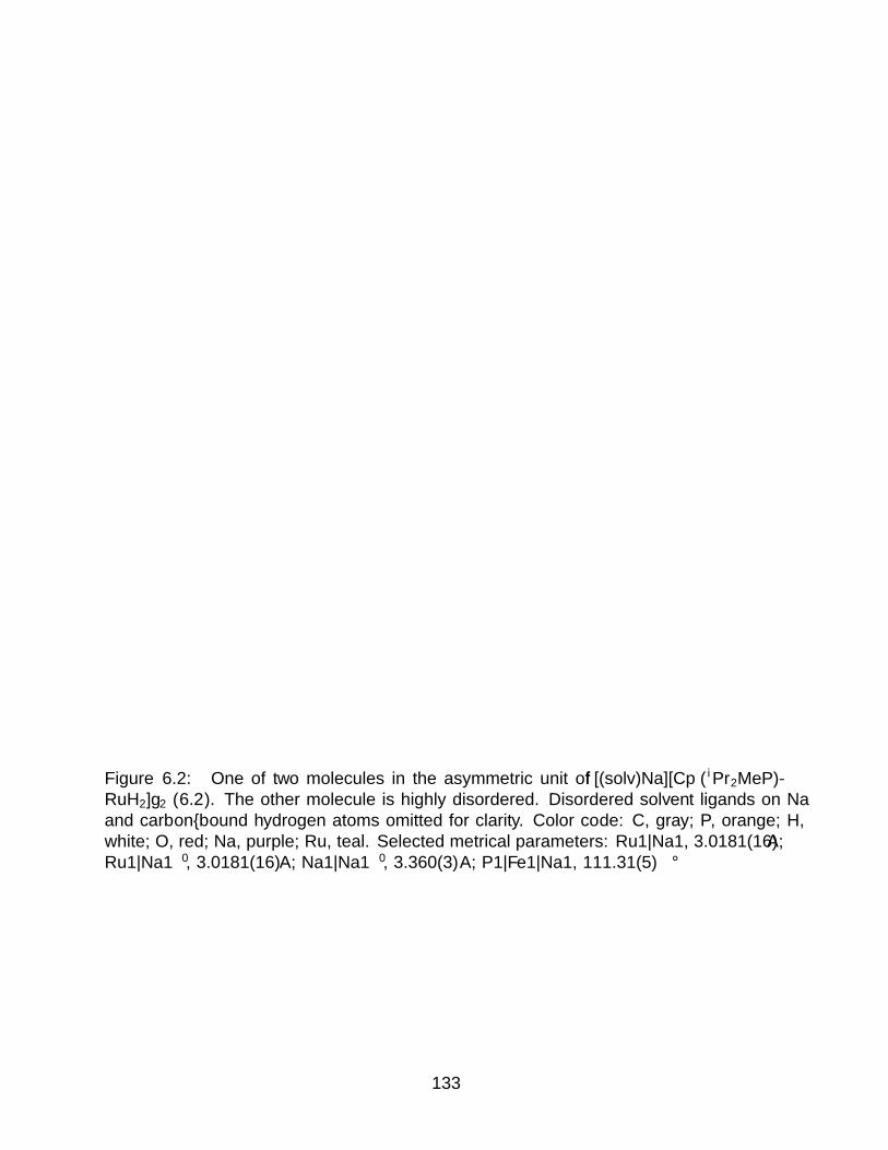
Figure 6.2: One of two molecules in the asymmetric unit of {[(solv)Na][Cp∗(iPr2MeP)-RuH2]}2 (6.2). The other molecule is highly disordered. Disordered solvent ligands on Naand carbon–bound hydrogen atoms omitted for clarity. Color code: C, gray; P, orange; H,white; O, red; Na, purple; Ru, teal. Selected metrical parameters: Ru1—Na1, 3.0181(16) A;Ru1—Na1′, 3.0181(16) A; Na1—Na1′, 3.360(3) A; P1—Fe1—Na1, 111.31(5)°
133

dered, and modeling the structure requires extensive restraints on the disordered molecule.In the solid state, the hydride ligands are not related by symmetry, with each Na atom inclose contact with three hydride ligands. This structure is not reflected by NMR spectroscopyat room temperature in benzene–d 6 solution, which indicates that the hydride ligands areequivalent (δRuH = −15.41 ppm, J PH = 31.5 Hz).
Hydride transfer from 6.2 to 6.1. Treatment of a pentane slurry of 6.2 with twoequivs of 6.1 in pentane resulted in precipitation of NaCl and a color change from purpleto orange-red (6.3). Workup and crystallization from diethyl ether gave a yellow powderthat rapidly decomposes in aromatic solvents such as benzene and toluene; therefore, NMRspectra were acquired with cyclohexane–d12 as solvent. Three overlapping doublets areobserved in the Ru—H region of the 1H NMR spectrum (δ = −11.07, J PH = 40.8 Hz;−11.09, J PH = 40.9 Hz; and −11.22 ppm, J PH = 39.7 Hz; δRu-H = −15.62 ppm for 6.2in cyclohexane–d12). The CHN combustion analysis of the isolated solid indicated that it islikely comprised of mainly 6.4.*
pentaneRu
PH
HNa
NaRu
PH
H
Solv
Solv
Ru
PN2
HPSfrag replacements
6.2
6.1
6.4
(6.3)
The resonance at −11.22 ppm was reduced in magnitude after several freeze–pump–thaw cycles, with a corresponding increase in the magnitude of the two doublets at −11.07and −11.09 ppm (relative to an internal standard of hexamethylbenzene). Based on thesedata, the resonance at −11.22 ppm is assigned to Cp∗(iPr2MeP)RuH(N2) (RuN2) and theresonances at −11.07 and −11.09 ppm are assigned as diastereomers of the nitrogen–bridgedcomplex Cp∗(iPr2MeP)RuH(µ−N2)HRu(iPr2MeP)Cp∗ (the meso compound 6.5 and a pairof enantiomers, 6.6; Scheme 6.1). Subsequent exposure to 1 atm of H2 in pentane resultedin conversion of all three compounds to the trihydride 6.3 over the course of 20 h.
Vibrational spectroscopy supports these structural assignments. A dinitrogen stretch isobserved in the solution IR spectrum of the 6.4/6.5/6.6 mixture in cyclohexane at νN2 =2090 cm–1 (Figure 6.3, top), and the complementary resonance Raman spectrum (514 nmexcitation) exhibits the expected three N2 stretches, at νN2 = 2039 cm–1, 2049 cm–1 and 2092cm–1 (Figure 6.3, bottom). The dinitrogen stretches for compounds 6.5 and 6.6 are verysimilar in energy and lower in energy than the stretch observed for 6.4, as expected for thesevery similar bridging dinitrogen compounds. The energies of these bands are comparable topreviously–reported [Ru2(µ–N2)] complexes.48 In both spectra, broad bands correspondingto Ru—H stretching modes are observed from 1850–1950 cm–1 (Figure 6.3). While these
*Anal calcd. for 6.4: C, 51.37; H, 8.37; N, 7.05. Found: C, 51.67; H, 8.24; N, 3.59; cf. C, 53.24; H, 8.67;N, 3.65 for 6.5/6.6
134

Ru
P
N
H
Ru
PN2
H
N Ru
P
H
Ru
P
N
H
N Ru
P
H
−N2 −N2
PSfrag replacements
6.4
6.5 6.6
Scheme 6.1: Proposed equilibria between 6.4, 6.5 and 6.6.
Figure 6.3: Infrared (top) and resonance Raman (bottom) spectra of the mixture of 6.4, 6.5and 6.6 in cyclohexane. A Gaussian function is centered at 1905 cm–1 (red), and Lorenztiansare centered at 2039 cm–1 (orange), 2049 cm–1 (green), and 2092 cm–1 (bue) were fit to theRaman spectrum, and a Gaussian centered at 1896 cm–1 (red) and a Lorenztian centered at2090 cm–1 (blue) were fit to the IR data. Residuals are shown in grey.
135
bands are putatively the result of overlapping contributions from 6.4/6.5/6.6, deconvolutioninto their components is not straightforward.
While the monomeric complex 6.4 is an analogue of the Fe dinitrogen complex 2.6,49
there are some important differences in the behavior of these two compounds. The Fe ana-logue does not detectably dimerize to form analogues of 6.5 or 6.6; even after removal ofnitrogen, no additional resonances attributable to dimeric complexes were detected.49 Thelarger size of Ru (vs. Fe) reduces the steric demands at the metal center in these systems,allowing dimerization in the Ru case.
6.3 Synthesis of Heterobimetallic Complexes
Reactions of 6.2 with other metal halide complexes leads to formation of hydride–bridgedheterobimetallic complexes (rather than H–transfer as in eq 6.3). For example, 6.2 reactedwith 1 equiv [(COD)IrCl]2 in Et2O to form Cp∗(iPr2MeP)Ru(µ–H)2Ir(COD) (6.7, eq 6.4).In the solid–state structure (Figure 6.4), the Ru—Ir distance is 2.5659(2) A, a relativelyshort distance enforced by the slightly puckered Ru(µ–H)2Ir core (Σ6 = 355.13(1)°) The Iris in a square planar coordination environment defined by the hydride ligands and two CODolefin centroids (Σ 6 = 359.9°).
[(COD)IrCl]2
pentaneRu
PH
HIr
½
PSfrag replacements
6.2
6.7
(6.4)
The 1H NMR spectrum of 6.7 is consistent with a Cs symmetric geometry. The bridgingRu—H—Ir resonance of −9.52 ppm appears somewhat upfield of the hydride shift in 6.2;more significantly, the H—P coupling constant in 6.7 is much smaller than that of 6.2 (J PH
= 15.2 Hz, cf. 31.5 Hz for 6.2). This is most likely due to a high degree of covalency in theIr—H bonds of the [Ru(µ–H2)Ir] core of 6.7, resulting in decreased covalency in the Ru—Hlinkages relative to those in the [Ru(µ−H2)Na] core of 6.2.
Complex 6.2 also reacted with two equiv of (IPr)CuCl to form the yellow hydride–bridgedheterobimetallic complex Cp∗(iPr2MeP)Ru(µ–H)2Cu(IPr) (6.8, Figure 6.5, eq 6.5). Thiscomplex features a slightly puckered [Ru(µ–H)2Cu] core (Σ 6 = 352.795(5)°), trigonal planarcoordination about Cu (Σ 6 = 359.781(3)°), and a Ru—Cu distance of 2.4833(4) A.
Ru
PH
HCu
N
NDipp
Dipp
IPrCuCl
Et2O½½
PSfrag replacements
6.26.2
6.8
(6.5)
136

Figure 6.4: Solid–state structure of Cp∗(iPr2MeP)Ru(µ–H)2Ir(COD) (6.7). Carbon–bound hydrogen atoms omitted for clarity. Color code: C, gray; P, orange; H, white; O,red; Ir, blue; Ru, teal. Selected metrical parameters: Ru1—Ir1, 2.5659(5) A; Ru1—P1,2.3074(14) A; P1—Ru1—Ir1, 93.01(4)°.
137

Table 6.1: Comparison of NMR and IR spectroscopic data for 6.2, 6.7 and 6.8.
δRuH (ppm) J PH (Hz) ν1RuH (cm–1) ν1
RuH (cm–1)
6.2 −15.41 31.5 1811 1709
6.7 −9.52 15.2 ca.1550a ca. 1440a
6.8 −14.65 23.9 1659 ca. 1570a
aBroad IR bands partially obscured by other features.
The 1H NMR spectrum of 6.8 is consistent with Cs symmetry, with the two bridginghydrides manifested as a single resonance at −14.65 ppm with an H—P coupling constant(J PH = 23.9 Hz) intermediate between the values for 6.2 (31.5 Hz) and 6.7 (15.2 Hz). Thedifferent values for the coupling constants between these three complexes presumably reflecta variability in the strength of the bonding interactions of [Cp∗(iPr2MeP)Ru] to bridginghydride ligands (Table 6.1).
Infrared spectra of 6.2, 6.7 and 6.8 also suggest that Ru—H bonding decreases instrength from 6.2 > 6.8 > 6.7 (Table 1). While the IR spectrum of 6.2 has two bandsclearly attributable to Ru—H stretches at 1811 and 1709 cm–1, these bands redshift in 6.8to 1659 and ca. 1570 cm–1; for 6.7 these bands are even lower in energy, at ca. 1550 and1440 cm–1. The lowest-energy (< 1600 cm–1) bands are partially obscured by other features,making conclusive assignment of their energies difficult. This redshift is consistent with anincrease in H—M (M = Ir, Cu) bond strength and a corresponding decrease in RuH bondstrength for such a bridging ligand.
6.4 Conclusion
The results described above demonstrate the utility of 6.2 as a hydride–based nucleophileto form bimetallic complexes, expanding the scope29,38–42 of nucleophilic Ru hydride anionsto the ubiquitous half–sandwich architecture. The stability of bimetallic complexes withbridging µ–N2 or µ−H ligands may reflect a high degree of electrophilicity on Ru in theCp∗(iPr2MeP)RuH fragment, which is conserved between these structures; the dinitrogenequilibrium products should serve as a convenient synthon for this fragment. Between 6.2and this Cp∗(iPr2MeP)RuH synthon, functionalization at Ru in the [Cp∗(iPr2MeP)Ru] frag-ment can make use of either electrophilic or nucleophilic strategies. Such studies with group14 elements are currently underway.
6.5 Experimental Section
General Considerations. All manipulations were carried out using standard Schl-enk or inert atmosphere glovebox techniques with an atmosphere of dry dinitrogen. Pen-tane was dried over activated alumina and stored over molecular sieves (4 A) prior to use.benzene–d 6 was degassed with 3 freeze–pump–thaw cycles and stored over activated molec-ular sieves (4 A) for 24 h prior to use. [(COD)IrCl]2 was purchased from Strem chemicals.IPrCuCl was prepared by the reaction of free IPr with CuCl in THF; purification followed lit-
138

Figure 6.5: Solid–state structure of Cp∗(iPr2MeP)Ru(µ–H)2Cu(IPr) (6.8). Carbon–boundhydrogen atoms omitted for clarity. Color code: C, gray; P, orange; H, white; O, red; N, blue;Ru, teal; Cu, orange–red. Selected metrical parameters: Ru1—Cu1, 2.4833(4) A; Ru1—P1,2.2492(8) A; P1—Ru1—Cu1, 97.74(2)°.
139

erature procedures.50 Cp∗(iPr2MeP)RuCl51,52 and Cp∗(iPr2MeP)RuH347,53,54 were prepared
by literature procedures.NMR spectra were recorded using Bruker Avance 400, 500, or 600 MHz spectrometers
equipped with a 5 mm broad band probe. Spectra were recorded at room temperature(ca. 22 °C) and referenced to the residual protonated solvent for 1H. 31P{1H} NMR spectrawere refer-enced relative to 85% H3PO4 external standard (δ = 0). 13C{1H} NMR spectrawere calibrated internally with the resonance for the solvent relative to tetramethylsilane.For 13C{1H} NMR spectra, resonances obscured by the solvent signal are omitted. Thefollowing abbreviations have been used to describe infrared features: s for strong, m formedium, w for weak, v for very, b for broad. Elemental analyses were performed by theCollege of Chemistry Microanalytical Laboratory at the University of California, Berkeley.
Resonance Raman Spectroscopy. Solutions of of 0.1 mM 6.4/6.5/6.6 was pre-pared in cyclohexane and flame sealed inside borosilicate pipette tips (I.D. 1.5 mm) underan atmosphere of nitrogen gas. Resonance Raman spectra were acquired with 3 mW of514.5 nm light. Samples were translated perpendicular to the beam at a rate of 0.5 mm/s tomitigate the effects of photoalteration. Both polarizations of scattered light were collectedthrough a 100 um slit in a 90° scattering geometry. Spectra were resolved in a 2 m Spex1401 double spectrograph and readout on a liquid nitrogen cooled CCD (Roper ScientificLN/CCD 1100).
Synthesis of {[Na(solv)][Cp∗(iPr2MeP)RuH2]}2 (6.2). Two equivs of NaBHEt3
(1 mL, 1.0 M in THF) were added to a solution of 6.1 (200 mg, 0.5 mmol) in 10 mLof Et2O at −35 °C. The deep purple solution rapidly changed color to orange–yellow. Thesolution was allowed to warm to room temperature with stirring for 2 h and was then filteredthrough Celite. After removal of volatile components in vacuo, the resulting yellow solid wasrecrystallized from Et2O (ca. 10 mL) at −35 °C. Yield: 0.147 g, 64 % over two crops. AnalCalcd. for C17H34NaPRu: C, 51.89; H, 8.71. Found: C, 52.08; H, 9.05; for analysis thecrystals were dried in vacuo for 12 h to remove Na–coordinated solvent. 1H NMR (400 MHz,benzene–d 6) δ 3.72–3.48 (m, 2H, THF OCH 2), 3.26 (q, J = 7.0 Hz, 2H, Et2O OCH 2), 2.18(s, 15H, Cp∗), 1.72 (h, J = 7.0 Hz, 2H, PCH Me2), 1.47–1.37 (m, 2H, THF OCH2CH 2),1.19–1.02 (m, 18H; PCH 3, PCHCH 3, Et2O OCH2CH 3), −15.42 (d, J = 31.5 Hz, 2H, RuH );Chemical shifts and integrations given for ca. 1:1 THF:Et2O. 13C{1H} NMR (101 MHz,benzene–d 6) δ 84.12, 67.87, 65.93, 27.74 (d, J = 19.5 Hz), 25.81, 19.50 (d, J = 6.3 Hz),18.29, 15.61, 14.43, 12.61.. 31P{1H} NMR (162 MHz, benzene–d 6) δ 64.22.
Synthesis of [Cp∗(iPr2MeP)RuH]nN2 (6.4, n = 1; 6.5 and 6.6, n = 2). Asolution of 6.1 (0.088 g, 0.22 mmol) in 2 mL of pentane was added to a slurry of 6.2 (0.100g, 0.22 mmol) in 2 mL of pentane. The resulting solution was stirred for 1 h, over whichtime it turned from bright purple to red–orange. The solution was filtered and concentratedin vacuo to give a yellow–orange residue. This was crystallized from Et2O (4 mL) at −35 °Cto give a microcrystalline yellow powder. Yield: 0.067 g, 39 % (for n = 1). Anal Calcd. forCp∗(iPr2MeP)RuHN2: C, 51.37; H, 8.37; N, 7.05. Found: C, 51.67; H, 8.24; N, 3.59. Thelow nitrogen content is likely due to incomplete combustion or loss of dinitrogen. 1H NMR(600 MHz, cyclohexane–d12) δ 1.85 (s), 1.84 (s), 1.80–1.65 (m), 1.13 (dd, J = 15.2, 7.2 Hz),1.09–0.97 (m), 0.95 (d, J = 7.0 Hz), 0.85 (dd, J = 15.6, 7.1 Hz), −11.07 (d, J = 40.8 Hz,2H, 6.5 and 6.6 RuH ), −11.08 (d, J = 40.9 Hz, 5/6 RuH), −11.22 (d, J = 39.7 Hz, 6.4RuH ). 31P{1H} NMR (243 MHz, cyclohexane–d12) δ 59.41, 59.08, 55.70.
140

Synthesis of Cp∗(iPr2MeP)Ru(µ–H)2Ir(COD) (6.7). A solution of [(COD)Ir-Cl]2 (0.036 g, 0.055 mmol) in 4 mL of Et2O was added to a stirred solution of 6.2 (0.050g, 0.055 mmol) in 2 mL of Et2O. The solution rapidly became deep red. After stirring for30 m, the volatile components were removed in vacuo and the resulting deep red residuewas extracted with 2 x 4 mL pentane. The combined extracts were concentrated to 1 mLand stored at −35 °C to afford deep red blocks. Yield: 0.028 g, 38 %. Anal cald. forC25H50IrPRu: C, 44.49; H, 7.47. Found: C,44.87; H, 7.09. 1H NMR (600 MHz, benzene–d 6)δ 4.20 (d, J = 4.0 Hz, 4H, COD CH ), 2.31 (s, 2H, COD CH 2), 2.11 (s, 2H, COD CH 2),1.87 (d, J = 1.6 Hz, 15H, Cp∗), 1.80–1.69 (hept, J = 7.0 Hz, 2H, PCH Me2), 1.61 (s, 2H,COD CH 2), 1.56 (s, 2H, COD CH 2), 1.25 (d, J = 6.6 Hz, 3H, PCH 3), 1.17 (dd, J = 15.2,7.0 Hz, 6H, PCHCH 3), 0.97 (dd, J = 13.4, 6.9 Hz, 6H, PCHCH 3), −9.52 (d, J = 15.2 Hz,2H, Ru(µ–H )Ir). 13C{1H} NMR (151 MHz, benzene–d 6) δ 128.35, 84.78 (d, J = 2.4 Hz),32.69 (br), 30.67 (d, J = 23.7 Hz), 18.84 (d, J = 4.5 Hz), 18.14, 13.22, 9.21 (d, J = 16.0Hz). 31P{1H} NMR (243 MHz, benzene–d 6) δ 53.66.
Synthesis of Cp∗(iPr2MeP)Ru(µ–H)2Cu(IPr) (6.8). Complex 6.2 (0.060 g,0.13 mmol) was dissolved in 6 mL of Et2O and the resulting solution was added dropwise toa suspension of IPrCuCl (0.060 g, 0.13 mmol) in 2 mL of Et2O. The resulting solution wasstirred for 30 min and then filtered before the volatile components were removed in vacuoThe resulting yellow residue was recrystallized from 4 mL of pentane. Yield: 0.080 g, 76 %.Anal calcd. for C44H70CuN2PRu: C, 64.24; H, 8.57; N, 3.77. Found: C, 63.69; H, 8.80; N,3.35. 1H NMR (600 MHz, benzene–d 6) δ 7.24 (t, J = 7.8 Hz, 2H, Dipp p–CH ), 7.13 (d,J = 7.8 Hz, 4H, Dipp m–CH ), 2.86 (hept, J = 6.9 Hz, 4H, Dipp CH Me2), 2.02 (d, J =1.1 Hz, 15H, Cp∗), 1.54 (d, J = 6.9 Hz, 12H, Dipp CHCH 3), 1.37 (hept, J = 6.9 Hz, 2H,PCH Me2), 1.08 (d, J = 6.9 Hz, 12H, Dipp CHCH 3), 1.05–0.98 (m, 12H, PCHCH 3), 0.69(d, J = 6.1 Hz, 3H, PCH 3), −14.65 (d, J = 23.9 Hz, 2H, Ru(µ–H )Cu). 13C{1H} NMR (151MHz, benzene–d 6) δ 145.81, 136.70, 130.05, 128.35, 124.34, 121.58, 86.21 (d, J = 2.2 Hz),28.97 (d, J = 19.9 Hz), 28.95, 24.51, 23.96, 19.28 (d, J = 6.0 Hz), 18.13, 13.96. 31P{1H}NMR (243 MHz, benzene–d 6) δ 62.97.
Variable pressure NMR of 6.4/6.5/6.6. The solid isolated from recrystallizationof a mixture of 6.4/6.5/6.6 (0.0057 g) and an internal standard of C6Me6 (0.0019 g, 0.012µmol) were dissolved in 0.5 mL cyclohexane–d6 (0.5 mL) and placed in a J–Young tube. A1H NMR spectrum was recorded as a starting point. The solution was subjected to 5 freeze–pump–thaw cycles, and another 1H NMR spectrum was recorded. Based on integrationagainst the internal standard, there was 0.012 µmol Ru—H containing products; assumingthe isolated solid consisted of solely 6.4, the expected value is 0.014 µmol; for 6.5/6.6 theexpected value is 0.015. These spectra are shown in Figure 6.6. The concentrations of thespecies involved are given in Table 6.2.
Reaction of 6.4/6.5/6.6 with hydrogen. The freeze–pump–thawed solution pre-pared above was exposed to 1 atm H2 and sealed. A spectrum was recorded immediately,and again after 20 h. Based on integration of the Cp∗ and Ru—H resonances against theinternal standard, the conversion was 99 %. 1H NMR (400 MHz, cyclohexane–d12) δ 1.99 (s,15H, Cp∗), 1.55 (hept, J = 7.0 Hz, 2H, PCH CH3), 1.01–0.96 (m, 9H, PCH 3 + PCHCH 3),0.94 (dd, J = 7.0, 3.3 Hz, 6H, PCHCH 3), −11.17 (d, J = 21.7 Hz, 3H, RuH 3). Thesespectra are shown in Figure 6.6. The concentrations of the species involved are given inTable 6.2.
141
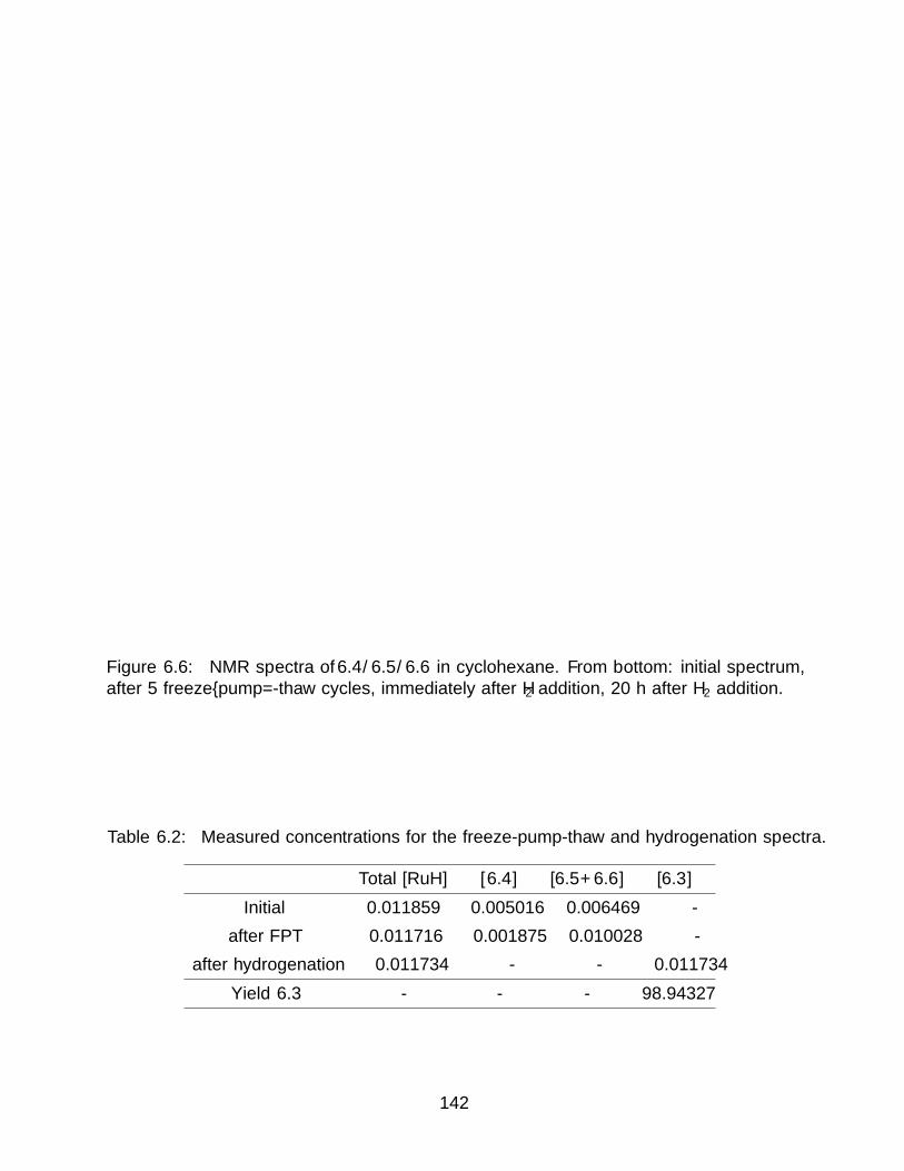
Figure 6.6: NMR spectra of 6.4/6.5/6.6 in cyclohexane. From bottom: initial spectrum,after 5 freeze–pump=-thaw cycles, immediately after H2 addition, 20 h after H2 addition.
Table 6.2: Measured concentrations for the freeze-pump-thaw and hydrogenation spectra.
Total [RuH] [6.4] [6.5+6.6] [6.3]
Initial 0.011859 0.005016 0.006469 -
after FPT 0.011716 0.001875 0.010028 -
after hydrogenation 0.011734 - - 0.011734
Yield 6.3 - - - 98.94327
142

6.6 Details of X–ray Diffraction Experiments
General considerations Single crystal X–ray diffraction experiments were carriedout at the UC Berkeley CHEXRAY crystallographic facility. Measurements of compoundswere performed on a Bruker APEX–II CCD area detector using Mo K radiation (λ =0.71073A) monochromated using QUAZAR multilayer mirrors. Specific details of each ex-periment can be found below. Tables of bond distances and angles are provided in AppendixA.
Table 6.3: Crystal parameters for Chapter 6
6.2 6.7 6.8
Formula C21.5H38.12NaOPRu C25H46IrPRu C44H70N2PCuRu
Crystal System triclinic monoclinic monoclinic
Space Group P−1 P21/c P21/n
a (A) 10.9113(4) 13.1252(11) 11.9852(6)
b (A) 12.7606(4) 10.1300(8) 17.9450(9)
c (A) 17.3568(6) 19.4665(15) 20.0906(10)
α (°) 88.1250(10) 90 90
β (°) 88.7720(10) 90.760(2) 100.3479(11)
γ (°) 89.0600(10) 90 90
V (A3) 2414.52(14) 2588.0(4) 4250.7(4)
Z 4 4 4
Radiation, λ (A) Mo Kα, 0.71073 Mo Kα, 0.71073 Mo Kα, 0.71073
ρ (calc’d, g cm−1) 1.287 5.791 1.285
µ (Mo Kα, mm−1) 0.741 0.685 0.924
Temperature (K) 100 100 100
2Θ range (°) 3.194 to 50.732 2.314 to 50.742 3.066 to 50.7
data/restraints/param 8775/268/690 9494/6/561 7775/0/468
R1 (I > 2σ) 0.0475 0.0491 0.0369
wR2 (I > 2σ) 0.0946 0.1071 0.0771
R1 (all data) 0.0747 0.0715 0.0518
wR2 (all data) 0.1113 0.1164 0.0857
GoOF 1.033 1.053 1.089
Crystallographic structure determination of 6.2. The structure was solved withthe SHELXS structure solution package using direct methods and refined with the ShelXLrefinement package using Least Squares minimization. The extensive disorder of the sec-
143

ond crystallographically independent {[Na(solv)][Cp∗(iPr2MeP)RuH2]}2 unit (one half of asymmetry–generated dimer) exhibited disorder which necessitated extensive use of ISORrestraints. The Ru atom was modeled over two positions. The disordered iPr2MeP wasmodeled over two positions with each bound to one of the disordered Ru positions, with oneof these modeled with a further, rotational disorder about the Ru—P bond. Occupanciesfor the Ru and iPr2MeP were treated as follows: both Ru atoms, both P atoms, and thealkyl groups on the nonrotationally–disordered iPr2MeP were refined against a free variable;the rotationally disordered components of the second iPr2MeP were each treated as hav-ing a fixed occupancy equal to 1−FV AR
2. Finally, the constitutionally disordered solvents on
both crystallographically independent fragments were treated as a disorder between THFand Et2O, whose occupancies sum to 1. The occupancies at each disordered solvent positionwere refined against a free variable. There were 3 free variables used for occupancy modelingin total.
Crystallographic structure determination of 6.7. The structure was solved withthe SHELXT structure solution package using intrinsic phasing and refined with the ShelXLrefinement package using Least Squares minimization.
Crystallographic structure determination of 6.8. The structure was solved withthe SHELXT structure solution package using intrinsic phasing and refined with the ShelXLrefinement package using Least Squares minimization.
6.7 References
[1] Churchill, M. R.; Ni, S. W. Y. Crystal structure and location of the bridging hydrideligand in µ–chloro–µ–hydrido–bis[chloro(pentamethylcyclopentadienyl)rhodium(III)], aHomonogeneous Hydrogenation Catalyst. J. Am. Chem. Soc. 1973, 95, 2150–2155.
[2] Green, M.; Howard, J. A.; Proud, J.; Spencer, J. L.; Stone, F. G. A.; Tsipis, C. A.A New Class of Hydride–bridged Platinum Complex with Application as Hydrosi-lylation Catalysts; Molecular and X–Ray Crystal Structure of trans–Di–µ–hydrido–bis(tricyclohexylphosphine)bis(triethylsilyl)diplatinum(Pt—Pt). J. Chem. Soc. Chem.Comm. 1976, 671–672.
[3] Kure, B.; Taniguchi, A.; Nakajima, T.; Tanase, T. Hydride-bridged NiRh complexeswith tunable N3S2 dithiolato ligands and their utilization as catalysts for hydrogenationof aldehydes and CO2 in aqueous media. Organometallics 2012, 31, 4791–4800.
[4] Chatterjee, B.; Gunanathan, C. Ruthenium catalyzed selective hydrosilylation of alde-hydes. Chem. Commun. 2014, 50, 888–890.
[5] Chen, J.; Chen, X.; Zhu, C.; Zhu, J. Room temperature polymerization of norbornenewith a hydride-bridged dinuclear ruthenium complex system. J. Mol. Catal. A Chem.2014, 394, 198–204.
[6] Tong, P.; Xie, W.; Yang, D.; Wang, B.; Ji, X.; Li, J.; Qu, J. Structural characterizationand proton reduction electrocatalysis of thiolate–bridged bimetallic (CoCo and CoFe)complexes. Dalt. Trans. 2016, 45, 18559–18565.
144
[7] Crimmin, M. R.; Hicken, A.; White, A. J. P. Selective Reduction of CO2 to a FormateEquivalent with Heterobimetallic Gold—Copper Hydride Complexes. Angew. ChemieInt. Ed. 2017, 15127–15130.
[8] Shvo, Y.; Czarkie, D.; Rahamim, Y.; Chodosh, D. F. A New Group of RutheniumComplexes: Structure and Catalysis. J. Am. Chem. Soc. 1986, 108, 7400–7402.
[9] Bianchini, C.; Meli, A.; Vacca, A.; Laschi, F.; Zanello, P.; Ramirez, J. A. Synthesis,Characterization, and Electrochemical Properties of a Family of Dinuclear RhodiumComplexes Containing Two Terminal Hydride Ligands and Two Hydride (or Chloride)Bridges. Stoichiometric and Catalytic Hydrogenation Reactions of Alkynes and Alken.Inorg. Chem. 1988, 27, 4429–4435.
[10] Fuchikami, T.; Ubukata, Y.; Tanaka, Y. Group 6 anionic µ−hydride complexes[HM2(CO)10]– (M = Cr, Mo, W): New catalysts for hydrogenation and hydrosilyla-tion. Tetrahedron Lett. 1991, 32, 1199–1202.
[11] Brunner, H.; Mijolovic, D. Enantioselective catalysis: Part 129. A new rhodium(I) com-plex with a µ2−H bridged Cp2WH2 ligand. J. Organomet. Chem. 1999, 577, 346–350.
[12] Tsipis, C. A.; Kefalidis, C. E. How efficient are the hydrido-bridged diplatinum cata-lysts in the hydrosilylation, hydrocyanation, and hydroamination of alkynes: A theoret-ical analysis of the catalytic cycles employing electronic structure calculation methods.Organometallics 2006, 25, 1696–1706.
[13] Esteruelas, M. A.; Garcia-Yebra, C.; Onate, E. [H(EtOH)2][{OsCl(η4−COD)}2(µ–H)-(µ–Cl)2] as an Intermediate for the Preparation of [OsCl2 (COD)]x and Its Activity asan Ionic Hydrogenation and Etherification Catalyst. Organometallics 2008, 27, 3029–3036.
[14] Albahily, K.; Al-Baldawi, D.; Gambarotta, S.; Koc, E.; Duchateau, R. Isolation of achromium hydride single–component ethylene polymerization catalyst. Organometallics2008, 27, 5943–5947.
[15] Chae, S. Y.; Do, W. L. Efficient dehydrogenation of amines and carbonyl com-pounds catalyzed by a tetranuclear ruthenium−µ−oxo−µ−hydroxo–hydride complex.Organometallics 2009, 28, 947–949.
[16] Barton, B. E.; Rauchfuss, T. B. Terminal hydride in [FeFe]-hydrogenase model has lowerpotential for H2 production than the isomeric bridging hydride. Inorg. Chem. 2008, 47,2261–2263.
[17] Bruschi, M.; Greco, C.; Kaukonen, M.; Fantucci, P.; Ryde, U.; De Gioia, L. Influence ofthe [2Fe]H subcluster environment on the properties of key intermediates in the catalyticcycle of [FeFe] hydrogenases: Hints for the rational design of synthetic catalysts. Angew.Chemie - Int. Ed. 2009, 48, 3503–3506.
[18] Lubitz, W.; Ogata, H.; Rudiger, O.; Reijerse, E. Hydrogenases. Chem. Rev. 2014, 114,4081–4148.
145

[19] Mulder, D. W.; Guo, Y.; Ratzloff, M. W.; King, P. W. Identification of a catalyticiron-hydride at the H-Cluster of [FeFe]-Hydrogenase. J. Am. Chem. Soc. 2017, 139,83–86.
[20] Wheatley, N.; Kalck, P. Structure and Reactivity of Early-Late Heterobimetallic Com-plexes. Chem. Rev. (Washington, D. C.) 1999, 99, 3379–3419.
[21] Ritleng, V.; Chetcuti, M. J. Hydrocarbyl ligand transformations on heterobimetalliccomplexes. Chem. Rev. 2007, 107, 797–858.
[22] Thomas, C. M. Metal-metal multiple bonds in early/late heterobimetallic complexes:Applications toward small molecule activation and catalysis. Comments Inorg. Chem.2011, 32, 14–38.
[23] Shibasaki, M.; Kanai, M.; Matsunaga, S.; Kumagai, N. Multimetallic MultifunctionalCatalysts for Asymmetric Reactions. Top Organomet Chem 2011, 37, 1–30.
[24] Cooper, B. G.; Napoline, J. W.; Thomas, C. M. Catalytic applications of early/lateheterobimetallic complexes. Catal. Rev. - Sci. Eng. 2012, 54, 1–40.
[25] Bodio, E.; Picquet, M.; LeGendre, P. “Early–Late” Heretobimetallic Catalysis and Be-yond. Top Organomet Chem 2016, 59, 139–18.
[26] Venanzi, L. Transition Metal Complexes with Bridging Hydride Ligands. Coord. Chem.Rev. 1982, 43, 251–274.
[27] Alcock, N. W.; Howarth, O. W.; Moore, P.; Morris, G. E. Carbonyl-free Hydride-bridgedMixed Organotransition Metal Complexes :. J. Chem. Soc. Chem. Comm. 1979, 1160–1162.
[28] Bruno, J. W.; Huffman, J. C.; Green, M. A.; Caulton, K. G. Hydride–Rich Zirconium–Osmium and Zirconium–Rhenium Dimers. J. Am. Chem. Soc. 1984, 106, 8310–8312.
[29] Chan, A. S. C.; Shieh, H.-S. New synthesis and molecular structure of potassium tri-hydridotris(triphenylphosphinne)ruthenate. J. Chem. Soc. Chem. Commun. 1985, 312,1379.
[30] Oishi, M.; Kato, T.; Nakagawa, M.; Suzuki, H. Synthesis and Reactivity of Ear-ly—Late Heterobimetallic Hydrides of Group 4 Metals and Iridium Supported byMono(η5−C5Me5) Ancillary Ligands: Bimetallic Carbon–Hydrogen Bond Activation.Organometallics 2008, 27, 6046–6049.
[31] Shima, T. Heterobimetallic polyhydride complex containing ruthenium and irid-ium. Synthesis and site-selectivity in the reaction with unsaturated hydrocarbons.Organometallics 2000, 19, 2420–2422.
[32] Moldes, I.; Delavaux-Nicot, B.; Lugan, N.; Mathieu, R. Synthesis, Structure and Reac-tivity toward Tetrafluoroboric Acid of a new Heterobimetallic Rhenium–Iridium Polyhy-dride Complex (CO)(PPh3)2Re(µ–H)3IrH(PPh3)2. Inorg. Chem. 1994, 33, 3510–3514.
146

[33] He, Z.; Neibecker, D.; Mathieu, R. Synthesis and reactivity towards tetrafluoroboric acidof a new family of heterobimetallic polyhydride complexes [(CO)(PPh3)2HRe(µ–H)3-RhL2] (L = PPh3, 1,2,5–triphenylphosphole, or P(OMe)3). J. Organomet. Chem. 1993,460, 213–217.
[34] Poulton, J. T.; Folting, K.; Caulton, K. G. Reversible Dehydrogenation of a Hetero-bimetallic Polyhydride Compound. Organometallics 1992, 11, 1364–1372.
[35] Alvarez, D.; Lundquist, E. G.; Ziller, J. W.; Evans, W. J.; Caulton, K. G. Synthesis,Structure, and Applications of Transition-Metal Polyhydride Anions. J. Am. Chem.Soc. 1989, 111, 8392–8398.
[36] Lundquist, E. G.; Caulton, K. G.; Spencer, J. L. Heterobimetallic Hydride Complexes.1990, 27, 26–30.
[37] Gusev, D. G.; Lough, A. J.; Morris, R. H. New polyhydride anions and proton–hydride hydrogen bonding in their ion pairs. X–ray crystal structure determinationsof Q[mer–Os(H)3(CO)(PiPr3)2], Q = [K(18–crown–6) and Q = [K(1–aza–18–crown–6)]. J. Am. Chem. Soc. 1998, 120, 13138–13147.
[38] Moldes, I.; Nefedov, S.; Lugan, N.; Mathieu, R. Synthesis of Re-Ru heterobimetallicpolyhydride complexes. Study of the influence of ligands bonded to the monometallicprecursors on the nature of the isolated binuclear complexes. J. Organomet. Chem.1995, 490, 11–19.
[39] Weng, W.-q.; Arif, A. M.; Ernst, R. D. RuH3[P(C6H5)3]3– as a Ligand in Complxes
with M(CO)3 Fragments (M = Cr, Mo, W). J. Clust. Sci. 1996, 7, 629–641.
[40] Abdur-Rashid, K.; Gusev, D. G.; Lough, A. J.; Morris, R. H. Intermolecularproton–hydride bonding in ion pairs: Synthesis and structural properties of [K(Q)][MH5(PiPr3)2] (M = Os, Ru; Q=18–crown–6, 1–aza–18–crown-6, 1,10–diaza–18–crown–6). Organometallics 2000, 19, 834–843.
[41] Plois, M.; Hujo, W.; Grimme, S.; Schwickert, C.; Bill, E.; De Bruin, B.; Pottgen, R.;Wolf, R. Open-shell first-row transition-metal polyhydride complexes based on the fac–[RuH3(PR3)3]– building block. Angew. Chemie - Int. Ed. 2013, 52, 1314–1318.
[42] Baudry, D.; Ephritikhine, M. Synthesis of a hydride-rich uranium-rhenium dimer:[(p –F–C6H4)3P]2ReH6U(η –C5H5)3. J. Organomet. Chem. 1986, 311, 189–192.
[43] Freeman, J. W.; Arif, A. M.; Ernst, R. D. The ReH6[P(C6H5)3]2– ion as a ligand:
complexes with M(CO)3. Inorganica Chim. Acta 1995, 240, 33–40.
[44] Abdur-Rashid, K.; Gusev, D. G.; Landau, S. E.; Lough, A. J.; Morris, R. H. Organizingchain structures by use of proton–hydride bonding. The single–crystal X–ray diffractionstructures of [K(Q)][Os(H)5(PiPr3)2] and [K(Q)][Ir(H)4(PiPr3)2], Q = 18–crown–6 and1,10–diaza–18–crown–6. J. Am. Chem. Soc. 1998, 120, 11826–11827.
147

[45] Oishi, M.; Kino, M.; Saso, M.; Oshima, M.; Suzuki, H. Early–late heterobimetalliccomplexes with a Ta—Ir multiple bond: Bimetallic oxidative additions of C—H, N—H,and O—H bonds. Organometallics 2012, 31, 4658–4661.
[46] Ostapowicz, T. G.; Fryzuk, M. D. Anionic tantalum dihydride complexes: Hetero-bimetallic coupling reactions and reactivity toward small-molecule activation. Inorg.Chem. 2015, 54, 2357–2366.
[47] Arliguie, T.; Border, C.; Chaudret, B.; Devillers, J.; Poilblanc, R. Chloro– and hy-drido(pentamethylcyclopentadienyl)ruthenium complexes: anomalous NMR behaviorof C5Me5RuH3PR3 (R = CHMe2, Cy). Organometallics 1989, 8, 1308–1314.
[48] Aneetha, H.; Jimenez-Tenorio, M.; Puerta, M. C.; Valerga, P.; Mereiter, K. Bridgingand terminal half-sandwich ruthenium dinitrogen complexes and related derivatives: Astructural study. Organometallics 2002, 21, 628–635.
[49] Smith, P. W.; Tilley, T. D. Silane–Allyl Coupling Reactions of Cp∗(iPr2MeP)Fe(η3−-allyl) and Synthetic Access to the Hydrido–Dinitrogen Complex Cp∗(iPr2MeP)FeH(N2).Organometallics 2015, 34, 2134–2138.
[50] Kaur, H.; Zinn, F. K.; Stevens, E. D.; Nolan, S. P. (NHC)CuI (NHC = N–HeterocyclicCarbene) Complexes as Efficient Catalysts for the Reduction of Carbonyl Compounds.Organometallics 2004, 23, 1157–1160.
[51] Tenorio, M. J.; Mereiter, K.; Puerta, M. C.; Valerga, P. Structural characterization ofcationic 16–electron half-sandwich ruthenium phosphine complexes with and withoutagostic interaction [3]. J. Am. Chem. Soc. 2000, 122, 11230–11231.
[52] Hayes, P. G.; Waterman, R.; Glaser, P. B.; Tilley, T. D. Synthesis, structure, andreactivity of neutral hydrogen-substituted ruthenium silylene and germylene complexes.Organometallics 2009, 28, 5082–5089.
[53] Suzuki, H.; Lee, D. H.; Oshima, N.; Morooka, Y. Hydride and Borohydride Derivatives of(Pentamethylcyclopentadienyl)(tertiary phosphine)ruthenium. Organometallics 1987,6, 1569–1575.
[54] Osipov, A. L.; Gerdov, S. M.; Kuzmina, L. G.; Howard, J. A. K.; Nikonov, G. I. Synthe-ses and X–ray diffraction studies of half–sandwich hydridosilyl complexes of ruthenium.Organometallics 2005, 24, 587–602.
148
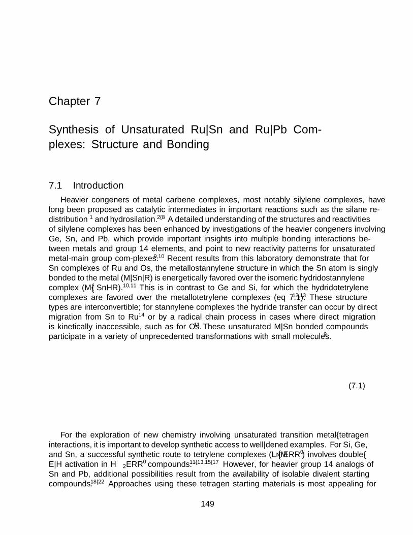
Chapter 7
Synthesis of Unsaturated Ru—Sn and Ru—Pb Com-
plexes: Structure and Bonding
7.1 Introduction
Heavier congeners of metal carbene complexes, most notably silylene complexes, havelong been proposed as catalytic intermediates in important reactions such as the silane re-distribution1 and hydrosilation.2–8 A detailed understanding of the structures and reactivitiesof silylene complexes has been enhanced by investigations of the heavier congeners involvingGe, Sn, and Pb, which provide important insights into multiple bonding interactions be-tween metals and group 14 elements, and point to new reactivity patterns for unsaturatedmetal-main group com-plexes.9,10 Recent results from this laboratory demonstrate that forSn complexes of Ru and Os, the metallostannylene structure in which the Sn atom is singlybonded to the metal (M—Sn—R) is energetically favored over the isomeric hydridostannylenecomplex (M––SnHR).10,11 This is in contrast to Ge and Si, for which the hydridotetrylenecomplexes are favored over the metallotetrylene complexes (eq 7.1).12,13 These structuretypes are interconvertible; for stannylene complexes the hydride transfer can occur by directmigration from Sn to Ru14 or by a radical chain process in cases where direct migrationis kinetically inaccessible, such as for Os.11 These unsaturated M—Sn bonded compoundsparticipate in a variety of unprecedented transformations with small molecules.9
E = SnM
LH H
EAr M
LH
E
H
E = Ge, Si
Ar(7.1)
For the exploration of new chemistry involving unsaturated transition metal–tetrageninteractions, it is important to develop synthetic access to well—defined examples. For Si, Ge,and Sn, a successful synthetic route to tetrylene complexes (LnM––ERR′) involves double–E—H activation in H2ERR′ compounds.11–13,15–17 However, for heavier group 14 analogs ofSn and Pb, additional possibilities result from the availability of isolable divalent startingcompounds.18–22 Approaches using these tetragen starting materials is most appealing for
149

access to metal–plumbylene derivatives, given the dearth of organolead hydrides that mightbe employed in approaches involving E—H additions.5
A well–established route to complexes with metal–main group bonds involves the reac-tion of an anionic transition metal complex with a main group halide derivative.23–25 Unsat-urated M—Sn and M—Pb complexes have previously been synthesized by salt metathesisreactions between anionic metal complexes and low–valent halide derivatives of the maingroup element. For example, Figueroas manganese anion Na[(ArDipp2C6H3NC)Mn(CO)3] re-acts with SnCl2 to give the chlorometallostannylene compound (ArDipp2NC)(CO)3MnSnCl,26
and Power has used CpM(CO)n– (n = 3, M = Cr, Mo, W; n = 2, M = Fe) species in reac-
tions with Ar′EX (Ar = m–terphenyl; E = Ge, Sn, Pb; X = Cl, Br) to form Cp(CO)nMEAr′
complexes.19,27,28 Terminal and bridging plumbylyne and stannylyne complexes have beensynthesized in an analogous manner.18,29–31
This Chapter describes syntheses of metallotetrylene complexes (M—E—R) of Ru de-rived from a synthon for Cp∗(iPr2MeP)RuH2, {[Na(solv)][Cp∗(iPr2MeP)RuH2]}2 (6.2, solv= THF, Et2O), which reacts as a salt metathesis partner with [DMPSnCl]2 and [ArTrip2-PbBr]2, resulting in formation of the corresponding metallotetrylenes. A synthon for Cp∗-(iPr2MeP)RuH binds DMPSnCl and ArTrip2PbBr, giving stannylene and plumbylene com-plexes with unusual geometries and bonding. In these complexes the group 14 elementdonates electron density to Ru from an orbital of E—C bonding parentage.
7.2 Synthesis and Characterization Complexes Featuring Unsat-urated Ru—E Interactions
Synthesis of metallotetrylenes (Cp∗(iPr2MeP)(H)2Ru—E—R). The ruthen-ate compound 6.2 is well–suited for nucleophilic substitution reactions that form novel Ru—E bonds (eq 7.2). Treatment of 6.2 with the chlorostannylene dimer [(DMP)SnCl]2
22 re-sulted in a color change from yellow to blue, with precipitation of NaCl. Similarly, reactionof 6.2 with the bromoplumbylene dimer [(ArTrip2)PbBr]2
18 generated a blue–green solution.Workup and crystallization from pentane allowed isolation of the metallostannylene Cp∗-(iPr2MeP)(H)2RuSn(DMP) (7.1, Figure 7.1), and the metalloplumbylene, Cp∗(iPr2MeP)-(H)2RuPb(ArTrip2) (7.2, Figure 7.2).
[ArEX]2
pentane
Ru
PH H
E
R
R
R = Mes, E = SnR = Trip, E = Pb
½PSfrag replacements
6.2
7.1
7.2
(7.2)
Compounds 7.1 and 7.2 have essentially identical coordination environments, differingmainly in their Ru—E and E—C bond distances. These structures differ markedly fromthose predicted by computational studies on similar Cp(Me3P)(H)2MEPh (M = Fe, Ru,
150

Figure 7.1: Solid–state structure of Cp∗(iPr2MeP)(H)2RuSn(DMP) (7.1). C–bound Hatoms omitted for clarity. C, gray; P, orange; Ru, teal; Sn, muted green. Selected metricalparameters: Ru1—Sn1, 2.6399(4) A; Ru1—P1, 2.2676(11) A; Sn1—C18, 2.270(4) A; P1—Ru1—Sn1, 108.01(3)°; Ru1—Sn1—C18, 117.97(10)°.
151

Figure 7.2: Solid–state structure of Cp∗(iPr2MeP)(H)2RuPb(ArTrip2) (7.2). C–bound Hatoms omitted for clarity. C, gray; P, orange; Ru, teal; Pb, dark gray. Selected metricalparameters: Ru1—Pb1, 2.6984(4) A; Ru1—P1, 2.2746(11) A; Pb1—C18, 2.356(4)A; P1—Ru1—Pb1, 107.75(3)°; Ru1—Pb1—C18, 119.28(9)°.
152

Os; E = Si, Ge, Sn, Pb) complexes.32 While the metallotetrylenes are computed to haverather acute M—E—C bond angles (99.2° for the metallostannylene and 98.7° for the met-alloplumbylene), compounds 7.1 and 7.2 have significantly larger bond angles of 118.0(1)°and 119.28(9)°, respectively. The experimentally determined M—E bond lengths (2.6401(4)and 2.6984(4) A) are in good agreement with the computed values (2.667 and 2.759 A for Snand Pb, respectively). These bonds were assigned as single Ru—E bonds with very little πcharacter.32 The differences between the structures computed by Pandey and Power32 andthose obtained experimentally may be attributed to the steric demands of the terphenyl sub-stituents, a conclusion supported by the X–ray structure of Cp∗(IXy)(H)2RuSnTrip whichis in much better agreement with the computed structures.14
The Ru—H 1H NMR resonances for 7.1 and 7.2 are significantly different, with chemicalshifts of −11.97 ppm for the metallostannylene 7.1 and −5.36 ppm for the metalloplumby-lene 7.2. The unusually downfield resonances for the hydride ligands of 7.2 would appearto be associated with the presence of the Pb atom. Spin–orbit coupling in heavy atoms in-duces spin polarization in the presence of a magnetic field, thus affecting the chemical shiftproportionally to the mass of the heavy atom and a Fermi contact term on the perturbedatom, termed the heavy atom effect on light atoms (HALA).33 The magnitude of this effectin 7.2 vs. 7.1 is large for a 2–bond interaction, indicating that there are moderate Ru—H···E interactions in 7.1 and 7.2; this conclusion is further supported by the moderate J EH
coupling constants (232 Hz for 7.1 and ca. 280 Hz for 7.2; 1J EH for E = Sn, Pb are typically2,000 ± 500 Hz).34 The HALA effect is also observed for the E—Cipso
13C resonances, whichappear at 188.26 ppm for 7.1 and at 275.60 ppm for 7.2.
Reactions of metallotetrylene complexes with MeI. Compound 7.1 reacted
with excess methyl iodide to give the stannyl complex, Cp∗(iPr2MeP)RuH2[SnIMe(DMP)](7.3; eq 7.3). The X–ray crystal structure of 7.3 (Figure 7.3) incorporates both stereoisomersresulting in posi-tional disorder of the Me and I groups. The RuSn distance of 2.578(5)A (average of two Sn positions) in 7.3 is slightly shorter than the corresponding Ru—Sndistance in 7.1, supporting assignment of a single Ru—Sn bond in 7.1. The geometry aboutSn is remarkable due to the distortion of bond angles away from the ideal tetrahedral value.The Ru—Sn—CAryl bond angle is 128.1(3)°, while the CMe—Sn—I angle is only 89.3(2)°(both angles are the average of two Sn, Me, and I positions); this geometric change appearsto reflect the high steric demands of the DMP substituent. Treatment of 7.2 with MeIresulted in formation of an intractable mixture of products.
MeI
pentane
Ru
PH H
Sn
Mes
Mes
Ru
PH H
Sn
Mes
Mes
IMe
PSfrag replacements
7.1 7.3
(7.3)
153
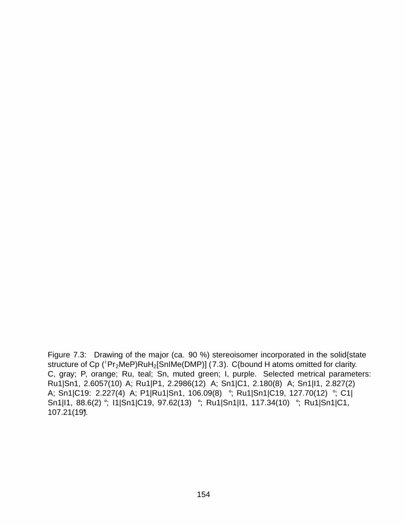
Figure 7.3: Drawing of the major (ca. 90 %) stereoisomer incorporated in the solid–statestructure of Cp∗(iPr2MeP)RuH2[SnIMe(DMP)] (7.3). C–bound H atoms omitted for clarity.C, gray; P, orange; Ru, teal; Sn, muted green; I, purple. Selected metrical parameters:Ru1—Sn1, 2.6057(10) A; Ru1—P1, 2.2986(12) A; Sn1—C1, 2.180(8) A; Sn1—I1, 2.827(2)A; Sn1—C19: 2.227(4) A; P1—Ru1—Sn1, 106.09(8)°; Ru1—Sn1—C19, 127.70(12)°; C1—Sn1—I1, 88.6(2)°; I1—Sn1—C19, 97.62(13)°; Ru1—Sn1—I1, 117.34(10)°; Ru1—Sn1—C1,107.21(19)°.
154

Synthesis of halotetrylene complexes (Cp∗(iPr2MeP)(H)RuE(X)R). The re-
action between 6.2 and the Ru chloride precursor complex Cp∗(iPr2MeP)RuCl has beenpreviously shown to produce an equilibrium mixture of Ru dinitrogen complexes in pentane(Chapter 6). This mixture was used as a Cp∗(iPr2MeP)RuH synthon in reactions with di-valent ArEX reagents ([DMPSnCl]2 or [ArTrip2PbBr]2), which resulted in color changes toburgundy (Sn) or deep red (Pb) (eq 7.4). In both cases, NMR spectra of the products inbenzene–d 6 indicate the presence of one major product exhibiting an Ru—H resonance thatintegrates 1:15 with the corresponding Cp∗ resonance. Workup of the reaction solutionsand recrystallization from pentane/O(SiMe3)2 provided deep purple crystals of Cp∗(iPr2-MeP)RuH[SnCl(DMP)] (7.4) and dark green crystals of Cp∗(iPr2MeP)RuH[PbBr(ArTrip2)](7.5).
[ArEX]2
pentaneRu
PN2
H
Ru
PH
E
X
R
RR = Mes, E = Sn, X = ClR = Trip, E = Pb, X = Br
PSfrag replacements
6.2 6.1
7.47.5
(7.4)
The J HE coupling constants observed for the 1H NMR Ru—H resonances of 7.4 and 7.5(215 and 250 Hz, respectively) are somewhat smaller than those observed for 7.1 and 7.2(232 and 280 Hz, respectively). The chemical shifts for the hydrides of 7.4 and 7.5 (−12.65and −12.11 ppm, respectively) are more similar to one another than the corresponding Ru—H resonances in 7.1 and 7.2 (−11.97 and −5.36 ppm). The smaller difference in chemicalshift between 7.4 and 7.5 (δδ = 0.54 for 7.4 and 7.5 vs 6.61 ppm for 7.1 and 7.2) and theslightly smaller coupling constants may reflect a weaker H···E interaction in the halotetrylenecomplexes 7.4 and 7.5. Consistently, this decrease in the coupling constant is mirrored in ablueshift in the νRuH bands in the IR spectra (νRuH = 1896 cm–1 for 7.4 vs. 1826 cm–1 for7.1; 1883 cm–1 for 7.5 vs. 1802 cm–1 for 7.2).
The 1H NMR spectrum of 7.4 at room temperature suggests there is a dynamic pro-cess occurring in solution. To probe these dynamics, 1H NMR spectra were recorded ina temperature range from 215 K to 330 K in toluene–d 8. These spectra show coalescencebehavior in the Me region from six distinct resonances at low temperature to only two athigh temperature, as well as a similar coalescence of the four mesityl meta-H resonances intoone (Figure 7.4). This coalescence behavior is remarkable, since rotation about either theRu—Sn or Sn—C bond would be expected to lead to coalescence into a three–line spectrumwith 1:1:1 intensity; such behavior is observed in 7.3, for which the Me resonances appearas 1:1:1 singlets.
One possible explanation for this behavior involves inversion of stereochemistry at Ruvia a pseudorotation mechanism similar to those proposed for half–sandwich Fe and Wsystems.35–37 While pseudorotation at Ru would not explain all the dynamics observed, a
155

Figure 7.4: Variable temperature NMR spectra (215 K to 350 K, ca. 11 K intervals) of the7.4 showing coalescence from a spectrum consistent with the C1 symmetric crystal structureinto a higher–symmetry spectrum. Left: coalescence behavior of the m–H positions of theDMP substituents (4 1:1:1:1 singlets coalescing into a singlet) superimposed upon the m–Hresonances of the central DMP aryl ring (2 1:1 doublets coalescing into a single doublet).Middle: the DMP Me region (6 1:1:1:1:1:1 singlets coalescing into two singlets at 2.4 and 2.2ppm that integrate 1:2) Residual CD2H resonance of toluene–d 8 omitted for clarity. Right:Ru—H resonance showing broadening at intermediate temperatures
156

MeE
MeD
MeFMeC
MeB
MeASn
RuH
Cp*
i MeB
MeC
MeAMeD
MeE
MeFSn
RuH
Cp*
Cl Cl
MeE
MeD
MeFMeC
MeB
MeASn
RuH
Cp*
Cl
ii
MeB
MeC
MeAMeD
MeE
MeFSn
RuH
Cp*
Cl
ii
i
Scheme 7.1: Two mechanisms by which the six inequivalent Me positions on DMP in 7.4can be exchanged. i. Rotation about the Sn—C bond; this process exchanges the A/F,C/D, and B/E positions. ii. Pseudorotation at Ru; this exchanges the C/B, E/D, andA/F positions. A combination of these two processes would give the 2:1 two-line patternobserved at high temperature. In this representation the ancillary iPr2MeP ligand is behindthe complex and omitted for clarity.
rotation about the Sn—C bond would lead to further averaging of the Me positions. Acombination of these processes would be expected to give the two–line spectrum observed athigher temperature (Scheme 7.1).
A similar situation exists for 6, whose NMR spectrum suggests that in this case thedynamic process in question is slow on the NMR timescale (at ambient temperature). Smallamounts of an ArTrip2 and Ru hydride–containing product of higher symmetry are observedin the 1H NMR of analytically pure samples of 7.5. Furthermore, the highly downfieldRu—H resonance for this second compound at −2.15 ppm suggests a HALA chemical shifteffect on the same order as 7.2. Treatment of this mixture (7.5 + solution impurity) withNaBHEt3 provides evidence these compounds are possibly isomers, as they are quantitativelytransformed into 7.2 as evidenced by integration against a Si(SiMe3)4 internal standard.Furthermore, the Ru—H resonances (of 7.5 and the solution impurity) exchange at roomtemperature as evidenced by EXSY NMR. These data suggest these two observed speciesare rotamers or constitutional isomers of one another.
Structural studies of 7.4 (Figure 7.5) and 7.5 (Figure 7.6) show that there are significantdifferences between the two compounds, despite the analogous formulations. Most notably,
157
Figure 7.5: Solid–state structure of Cp∗(iPr2MeP)RuH[SnCl(DMP)] (7.4). C–bound Hatoms omitted for clarity. C, gray; P, orange; Ru, teal; Sn, muted green; Cl, green. Selectedmetrical parameters: Ru1—Sn1, 2.4731(3) A; Ru1—P1, 2.2919(8) A; Sn1—Cl1, 2.4554(8) A;Sn1—C32, 2.198(3) A; P1—Ru1—Sn1, 97.85(2)°; Ru1—Sn1—C32, 146.39(9)°; Ru1—Sn1—Cl1, 94.02(9)°; Cl1—Sn1—C32, 94.02(9)°.
158

Figure 7.6: Solid–state structure of Cp∗(iPr2MeP)RuH[PbBr(ArTrip2)] (7.5). C–bound Hatoms omitted for clarity. C, gray; P, orange; Ru, teal; Pb, dark gray; Br, gold. Selectedmetrical parameters: Ru1—Pb1, 2.5370(7) A; Ru1—P1, 2.3043(19) A; Pb1—C18, 2.251(7)A; Pb1—Br1, 2.7530(8) A; P1—Ru1—Pb1, 96.26(5)°; Ru1—Pb1—C18, 156.64(16)°; Ru1—Pb1—Br1, 111.58(2)°; Br1—Pb1—C18, 88.91(16)°.
159

while the Ru—Sn—C angle for 7.4 is large for trigonal planar coordination (145.5(2)° vs120° expected for trigonal planar), the corresponding Ru—Pb—C angle for 7.5 is even larger(156.5(2)°), and the bond angles about Pb are more consistent with a T–shaped coordinationgeometry. Counterintuitively, the Pb—C distance in 7.5 is shortened to 2.251(7) A relativeto ArTrip2PbBrPy, which features a Pb—C bond distance of 2.322(4) A.
This shortening of the Pb—C bond trans– to Ru is suggestive of an inverse trans– in-fluence, a phenomenon that has been observed extensively in actinyl systems and mostrelevantly in KSnO(PO4).38–40 This effect is proposed to originate from differential polariz-ability of atoms with highest core and lowest valence orbitals of opposite parity.40 In Pb,the highest energy core orbitals are 5d, while the lowest energy valence orbitals are 6s; thus,an inverse trans– effect is expected. In the case of 7.5, this would result in a shorteningof the Pb—C bond Consistently, the Pb—Br bond in 7.5 is ca. 0.04 A longer than thePb—Br bond in ArTrip2PbBrPy (2.7530(2) A for 7.5 vs. 2.7063(6) A for ArTrip2PbBrPy).18
Alternatively, the decrease in the Pb—C bond distance could be attributed to electrostaticeffects arising from donation of electron density from Pb to Ru, increasing the partial chargeat Pb and thus shortening the bond to the partially negatively charged aryl ligand; however,this would not explain the observed increase in the Pb—Br bond distance in 7.5.
A similar, although weaker, effect is observed in 7.4, with the Sn—C distance (dSnC
=2.194(6) A) being slightly shorter than that in ArTrip2SnClPy (dSnC =2.229(4) A;41 struc-tural data for DMPSnClPy is not available) while the Sn—Cl distance is consistent withinerror (dSnCl = 2.449(2) A vs. dSnCl = 2.4478(19) A for ArTrip2SnClPy).41 The overall lowermagnitude of structural changes on coordination for Sn relative to Pb is due to two factors:first, Sn is overall less polarizable than Pb, leading to smaller trans– effects generally; andsecond, the more acute Ru—Sn—C angle brings the Sn—C and Sn—Cl bonds more out ofline from any effects of polarization at Sn by Ru.
7.3 Structure and Bonding in Metallotetrylene and TetryleneComplexes
Bonding in heavier main group element compounds can be significantly different thanin the lighter congeners. In particular, contraction of s orbitals results in diminished par-ticipation in bonding upon descending from the 2p to 3p elements;42 further, relativisticcontraction of the s orbital is expected to reinforce this trend, leading to the inert pair effectobserved for the heaviest p–block elements.43
Bonding in metallotetrylene complexes, 7.1 and 7.2. For 7.1 and 7.2, theHOMO is not a purely Sn–based lone pair as predicted by valence bond treatments, butrather is significantly involved in bonding to Ru and C (Figure 7.7) Using the coordinatesystem in Figure 7.7, this orbital has some characteristics of both a Ru—Sn—C σ–bondingMO and a Sn based lone pair, with Sn 5pz orbital parentage. The other Ru—Sn—C σ bond-ing MO is the HOMO−11, in this case with a node at Sn indicating 5px orbital parentage.As expected, π–bonding in these complexes is negligible; the HOMO−1 is of the propersymmetry for π–bonding to Sn, but it is almost exclusively Ru based, with a small amountof Ru—P π character. This leaves the LUMO with primarily Sn py character.
The residual electron density at Sn in the HOMO of 7.1 gives rise to the nucleophilicitydisplayed in the reaction with MeI, where it behaves similarly to a Sn–based lone pair. As
160

Figure 7.7: MO diagram and orbital isosurfaces depicting the σ-bonding interactions atthe Sn center in 7.1. A similar orbital manifold is apparent for 7.2
161

the 6s orbital is expected to contribute even less to bonding in 7.2 (relative to 5s in 7.1),the HOMO in 7.2 is expected to be more involved in bonding, making 7.2 overall lessnucleophilic than 7.1; this may be reflected in the differential reactivity these complexesdisplay toward MeI, with 7.2 reacting to form an intractable mixture of products while 7.1simply adds the MeI in a 1,1–fashion to Sn.
Bonding in tetrylene complexes, 7.4 and 7.5 As mentioned above, the anglesabout the E atoms in 7.4 and 7.5 are significantly distorted from ideal values, with Ru—E—C angles of 145.5(2)° in 7.4 and 156.5(2)° in 7.5, prompting an investigation into theirbonding structure. These differences might be attributed to the different steric demands ofthe DMP and ArTrip2 substituents, although the longer Ru—E and E—C bonds for the Pbanalogue should counteract this factor somewhat. An additional, perhaps more importantfactor relates to the greater tendency of the heavier p–block elements to utilize more pcharacter in forming bonds.42,43 For 7.4 and 7.5, this is manifested an increasingly T–shapedgeometry, resulting in a Ru—Pb—C angle of nearly 160° for 7.5.
Interestingly, the σ-bonding MOs in 7.4 and 7.5 appear to originate from the E—Cbonding manifold and have significant σ–E—C character (Figure 7.8). A 6p orbital on Einteracts with both the aryl σ orbital and a Ru 4d orbital, in what is essentially a 3–centered–2–electron bond; the resulting orbital manifests in the calculations as HOMO−11 for 7.4and HOMO−14 for 7.5 (Figure 7.8). The geometric differences between 7.4 and 7.5 canbe attributed to decreasing s character in the HOMO of the free tetrylene fragment, whicheventually acts as the donor orbital to form this σ–interaction. For 7.5, this orbital is muchmore of a pure 6p orbital at Pb, and thus the Pb atom in 7.5 prefers a more linear geometrythan Sn in 7.4. This effect is attributable to the relativistic contraction of the 6s orbital,making it much less accessible for bonding than 5s in Sn.
Central to any discussion of bonding in this system is the possibility of a multiple bondexisting between Ru and Sn or Pb. On first inspection, the shortening of both the Ru—Snand Ru—Pb bonds by ca. 0.15 A in 7.4 and 7.5 relative to 7.1 and 7.2 suggest there issome strengthening of the Ru—E bonding interaction in 7.4 and 7.5, consistent with thepresence of multiple bonding. The HOMO of 7.4 and 7.5 are of π character, with the LUMOrepresenting the corresponding antibonding orbital.
7.4 Conclusion
Compound 6.2 has provided access to two distinct strategies for forming bonds betweenRu and the heavier tetragens, Sn and Pb. The resulting compounds show dramatic dif-ferences in geometry upon moving from Sn to Pb, attributed to the increased relativisticcontraction of the 6s orbital. Importantly, the Ru—H chemical shift was observed to changedramatically between Sn and Pb for the metallotetrylene complexes 7.1 and 7.2, but muchless so for the halotetrylene complexes 7.4 and 7.5; this decreased HALA effect mirrors a de-crease in J HE coupling constant, suggesting the chemical shift differences between transitionmetal Sn– and Pb–bound systems may be a viable means of characterizing bonding in thesemolecules. DFT studies of these complexes identify several electronic features that reflect adecreasing participation of the 6s orbital on Pb in bonding (relative to Sn 5s). These fea-tures are manifested structurally for 7.4 and 7.5 as an increasingly linear Ru—E—C angle,reflecting increased 6p participation in bonding.
162

Figure 7.8: Orbital plots depicting the σ (HOMO−11), π (HOMO), and π∗ (LUMO)orbitals for the Ru––Sn bond in 7.4.
7.5 Experimental Section
General Considerations. All manipulations were carried out using standard Schl-enk or inert atmosphere glovebox techniques with an atmosphere of dry dinitrogen. Allsolvents were dried over activated alumina prior to use. Benzene–d 6 was subjected to 3freeze–pump–thaw cycles and stored over molecular sieves (4 A) prior to use. Cp∗(iPr2-MeP)RuCl,12,44 [(DMP)SnCl]2,22 [ArTrip2PbBr]2,18 and 6.2 (Chapter 6) were prepared byliterature procedures.
NMR spectra were recorded using Bruker Avance 400, 500, or 600 MHz spectrometersequipped with a 5 mm broad band probe. Spectra were recorded at room temperature (ca. 22°C) unless otherwise noted, and referenced to the residual protioisotopomer of the solvent for1H. 31P{1H} NMR spectra were referenced relative to 85% H3PO4 external standard (δ = 0).13C{1H} NMR spectra were calibrated internally with the resonance for the solvent relativeto tetramethylsilane. For 13C{1H} NMR spectra, resonances obscured by the solvent signalare omitted. Elemental analyses were performed by the College of Chemistry MicroanalyticalLaboratory at the University of California, Berkeley.
Synthesis of Cp∗(iPr2MeP)RuH2[Sn(DMP)] (7.1): A solution of [DMPSnCl]2(0.110 g, 0.237 mmol) in 6 mL Et2O was added dropwise to a solution of 6.2 (0.110 g,0.237 mmol) in 4 mL Et2O. This resulted in a color change from yellow to blue–green and
163

precipitation of a white solid that was presumably NaCl. After 1 h the solution was filteredthrough Celite, and concentrated in vacuo to give a deep blue–green solid. Crystallizationfrom pentane (4 mL) at −35 °C gave 7.1 as deep blue blocks. Yield: 0.149 g, 79 % Analcalcd. For C41H59PRuSn: C, 61.35; H, 7.41. Found: C, 61.07; H, 7.55.1H NMR (400 MHz,benzene–d 6) δ 7.37 (t, J = 7.5 Hz, 1H, DMP p–CH ), 7.14 (s, 1H; DMP o–CH ; the remainderof the doublet is obscured by C6D5H), 6.76 (s, 4H, Mes m–CH ), 2.47 (s, 12H, DMP o–Me),2.13 (s, 6H, DMP p–Me), 1.71 (s, 15H, Cp∗), 1.46 (hept, J = 7.0 Hz, 2H, PCH Me2), 1.09(d, J = 8.1 Hz, 3H, PCH 3), 0.87 (dd, J = 14.9, 7.1 Hz, 6H, PCHCH 3), 0.64 (dd, J = 12.7,6.8 Hz, 6H, PCHCH 3), -11.97 (d, J = 28.9, 232 Hz, 2H, RuH ). 13C{1H} NMR (101 MHz,benzene–d 6) δ 188.28, 146.23, 139.06, 136.13 (d, J = 9.0 Hz), 129.35, 129.29, 126.74, 93.68(d, J = 2.0 Hz), 26.15 (d, J = 24.0 Hz), 22.42, 21.13, 18.87 (d, J = 4.6 Hz), 17.91, 16.88 (d,J = 31.3 Hz), 11.68. 31P{1H} NMR (162 MHz, benzene–d 6) δ 65.76. FTIR (benzene–d 6):1826 (br, νRuH), 1744 (νRuH) cm–1.
Synthesis of Cp∗(iPr2MeP)RuH2[Pb(ArTrip2)] (7.2): A solution of A: [ArTrip2-PbBr]2 (0.080 g, 0.18 mmol) in 2 mL diethyl ether was added over the course of 1 h to 6.2(0.140 g, 0.18 mmol) in 2 mL diethyl ether. This resulted in a color change from yellow togreen, with precipitation of a colorless precipitate that was presumably NaBr. The solutionwas filtered through Celite and concentrated in vacuo to give a green powder. Crystallizationfrom pentane (2 mL) at −35 °C gave 7.2 as green blocks. Yield: 0.167 g, 87 %. FTIR(benzene–d 6): 1822 (br, νRuH), 1801 (νRuH) cm–1. B: A solution of NaBHEt3 (45 µL, 1.0 Min THF) was added to 7.5 (0.050 g, 0.044 mmol) in 4 mL Et2O. This resulted in a rapidcolor change from deep green to lighter green. After stirring for 20 m, the solution wasfiltered through Celite and concentrated in vacuo to give a green residue. Recrystallizationfrom pentane (2 mL) at −35 °C gave 7.2 as green blocks. Yield: 0.024 g, 52 %. Analcalcd. For C53H83PRuPb: C, 60.08; H, 7.90. Found: C, 59.98; H, 7.51. 1H NMR (500 MHz,benzene–d 6) δ 7.68 (d, J = 7.5 Hz, 2H, DMP m–CH ), 7.39 (t, J = 7.5 Hz, 1H, DMP o–CH ),7.14 (s, 4H, Trip m–CH ), 3.41 (hept, J = 6.9 Hz, 4H, Trip o–CH Me), 2.84 (hept,= 7.0 Hz,2H, Trip p–CH Me), 1.78 (s, 15H, Cp∗), 1.49 (m, 14H, Trip CHCH 2 + PCH Me), 1.39 (d, J= 8.1 Hz, 3H, PCH 3), 1.29 (d, J = 6.8 Hz, 12H, Trip CHCH 3), 1.22 (d, J = 6.7 Hz, 12H,Trip CHCH 3), 0.87 (dd, J = 14.9, 7.2 Hz, 6H, PCHCH 3), 0.64 (dd, J = 12.6, 6.7 Hz, 6H,PCHCH 3), −5.36 (d, J = 32.4, 280 Hz, 2H, RuH ). 13C{1H} NMR (126 MHz, benzene–d 6)δ 275.60, 147.74, 147.32, 146.37, 137.71, 136.96, 123.77, 121.40, 94.94, 34.79, 31.06, 27.32,24.97 (d, J = 24.1 Hz), 24.42, 18.71, 18.28, 18.245 (d, J = 32 Hz), 10.90. 31P{1H} NMR(202 MHz, benzene–d 6) δ 72.59.
Synthesis of Cp∗(iPr2MeP)RuH2[SnIMe(DMP)] (7.3): Methyl iodide (10 µL,0.15 mmol) was added to a solution of 7.1 (0.03 g, 0.037 mmol) in 10 mL of pentane. Thegreen color of the solution rapidly bleached, and a colorless precipitate formed. The volatilecomponents were removed under reduced pressure, and the resulting colorless solid waswashed with 1 mL of pentane. Yield: 0.03 g, 86 %. Crystals suitable for X–ray diffractionwere grown by slow diffusion of pentane into fluorobenzene at −35 °C. Anal calcd. ForC42H62IPRuSn: C, 53.40; H, 6.62. Found: C, 53.62; H, 6.60. 1H NMR (500 MHz, benzene–d 6) δ 7.17 (t, J = 7.6 Hz, 1H, DMP p–CH ), 6.96 (s, 2H, Mes m–CH ), 6.91 (s, 2H, Mesm–CH ), 6.87 (d, J = 7.5 Hz, 2H, DMP m–CH ), 2.47 (s, 6H, DMP CH 3), 2.43 (s, 6H, DMPCH 3), 2.27 (s, 6H, DMP CH 3), 1.62 (s, 15H, Cp∗), 1.47–1.33 (m, 2H, PCH Me), 0.91–0.75(m, 12H, PCH CH 3), 0.42 (d, J = 8.8 Hz, 3H, PCH 3), −10.32 (d, J SnH = 48.9, Hz J = 29.7
164

Hz, 1H, RuH ), −11.05 (d, J SnH = 94.5 Hz, J = 28.9 Hz, 1H, RuH ). 13C{1H} NMR (126MHz, Chloroform-d) δ 149.60, 144.84, 141.43, 137.93, 137.56, 136.31, 136.15, 130.16, 129.28,128.80, 95.43, 27.79 (d, J = 11.8 Hz), 27.58 (d, J = 10.8 Hz), 23.65, 23.09, 21.28, 19.06,18.79 (d, J = 3.3 Hz), 18.71 (d, J = 3.7 Hz), 17.83, 17.61, 13.27 (d, J = 32.6 Hz), 12.28.31P{1H} NMR (202 MHz, benzene–d 6) δ 61.49.
Synthesis of Cp∗(iPr2MeP)RuH[SnCl(DMP)] (7.4): A solution of 6.1 (0.051g, 0.107 mmol) in 2 mL of pentane was added to a slurry of 2 (0.045 g, 0.107 mmol) in 2 mLpentane. The resulting solution was stirred for 1 h, over which time it turned from brightpurple to red–orange. The solution was filtered and a slurry of [DMPSnCl]2 (0.100 g, 0.107mmol) in 4 mL of Et2O was added, at which point the solution rapidly changed color todeep burgundy and a deep burgundy precipitate formed. The mixture was concentrated invacuo to give a deep burgundy residue, which was recrystallized by dissolving in 4 mL ofTHF, followed by addition of 10 mL of pentane and storage at −35 °C. Yield: 0.104 g, 58% over 3 crops. Anal. Calc. for C41H58ClPRuSn: C, 59.41; H, 6.88. Found: C, 59.03; H,7.22. 1H NMR (600 MHz, benzene–d 6) δ 7.18 (t, J = 7.5 Hz, 1H, DMP p–CH ), 6.97 (d,J = 7.5 Hz, 2H, DMP o–CH ), 6.94–6.61 (s, 4H, Mes m–CH ), 2.84–1.91 (m, 18H; Obviouspeaks at 2.53 and 2.21 ppm, with a v. br peak at 2.09 ppm; DMP CH 3), 1.79 (s, 15H,Cp∗), 1.47–1.34 (m, 1H), 0.93–0.81 (m, 12H, PCH 3 + PCHCH 3), 0.77 (dd, J = 16.0, 7.1Hz, 3H, PCHCH 3), −12.66 (d, J = 31.1, 222 Hz, 1H, RuH ) Note that the multiplet from2.84-1.91 ppm will be significantly affected by field strength as these resonances are in theintermediate exchange regime, where peak broadening and position are determined by thedifference in peak posi-tions in Hz. 13C{1H} NMR (151 MHz, benzene–d 6) δ 174.18 (d, J =3.7 Hz), 137.17, 129.96, 128.95, 128.37, 91.66 (d, J = 1.6 Hz), 29.17 (d, J = 28.2 Hz), 22.68(d, J = 24.4 Hz) 22.65, 21.34, 19.40 (d, J = 5.5 Hz), 19.14 (d, J = 3.8 Hz), 18.45 (d, J =2.1 Hz), 17.17 (d, J = 4.4 Hz), 12.43. 31P{1H} NMR (162 MHz, benzene–d 6) δ 59.36. FTIR(C6H12): 1896 (br, νRuH) cm–1.
Synthesis of Cp∗(iPr2MeP)RuH[PbBr(ArTrip2)] (7.5): A solution of 6.1 (0.088g, 0.22 mmol) in 2 mL of pentane was added to a slurry of 6.1 (0.100 g, 0.11 mmol) in 2 mLof pentane. The resulting mixture was stirred for 1 h, over which time it turned from brightpurple to red-orange. The mixture was filtered and a solution of [ArTrip2PbBr]2 (0.336 g, 0.22mmol) in pentane (4 mL) was added, at which point the color rapidly changed to deep red.The solution was concentrated in vacuo, and the resulting green residue was recrystallizedby dissolving in 4 mL of pentane, followed by addition of 2 mL of O(SiMe3)2. The solutionwas then concentrated to ca. 5 mL and stored at −35 °C to give green crystals. Yield: 0.14g, 28 % over 2 crops. Anal. Calc. for C56H94BrPPbRu: C, 55.92; H, 7.26. Found: C, 55.60;H, 7.16. 1H NMR (600 MHz, benzene–d 6) δ 7.84 (d, J = 7.5 Hz, 1H, ArTrip2 m–CH ), 7.72(d, J = 7.4 Hz, 1H, ArTrip2 m–CH ), 7.64 (d, J = 7.5 Hz, MP), 7.38 (s, 1H, Trip m–CH ),7.28 (s, MP), 7.28 (s, 1H, Trip m–CH ), 7.24 (t, J = 7.5 Hz, 1HArTrip2 p–CH ), 7.20 (s, 1H,Trip m–CH ), 7.01 (s, 1H, Trip m–CH ), 4.08 (hept, J = 6.7 Hz, 1H, Trip CH CH3), 3.79(hept, J = 6.6 Hz, 1H, Trip CH CH3), 3.53 (m, 1H + MP, Trip CH CH3), 3.21 (hept, J = 6.8Hz, MP), 2.90 (hept, J = 7.0 Hz, 1H, Trip CH CH3), 2.78 (m, 2H, Trip CH CH3), 1.79 (d,J = 6.9 Hz, 3H, Trip CHCH 3), 1.72 (d, J = 6.6 Hz, 3H, Trip CHCH 3), 1.66 (s, 15H, Cp∗),1.63 (d, J = 6.8 Hz, 3H, Trip CHCH 3), 1.53 (d, J = 6.9 Hz, MP), 1.39 (s, MP), 1.37–1.32(m, 12H, Trip CHCH 3), 1.26 (m, 9H, Trip CHCH 3), 1.15 (d, J = 6.8 Hz, 3H, Trip CHCH 3),1.06 (d, J = 6.8 Hz, 3H, Trip CHCH 3), 1.00 (d, J = 7.0 Hz, 3H, Trip CHCH 3), 0.97 (m, 6H,
165

PCHCH 3), 0.84 (dd, J = 13.2, 6.8 Hz, 3H, PCHCH 3), 0.65 (m, 6H, PCHCH 3 + MP), 0.43(d, J = 6.5 Hz, 3H, PCH 3), -2.14 (d, J = 29.0 Hz, MP, RuH ), -12.10 (d, J = 33.4 Hz, 1H,RuH ). 31P{1H} NMR (243 MHz, benzene–d 6) δ 60.82, 45.66 (MP). MP refers to resonancesattributable to the minor equilibrium partner of 6. FTIR (C6H12): 1883 (br, νRuH) cm–1.
Reaction of 3 with NaBHEt3. Compound 7.5 (0.015 g, 16 µmol) and Si(SiMe3)4
(0.0025 g, 7.8 µmol) were dissolved in benzene–d 6 (0.5 mL). A 1H NMR spectrum wasrecorded, after which NaBHEt3 (6.5 µL, 3.0 M in THF) was added. The solution immediatelychanged color to lighter green. A 1H NMR spectrum of this reaction mixture showed completeconversion of both compounds associated with 7.5 to compound 7.2.
7.6 X–ray Diffraction Experiments.
Single crystal X–ray diffraction experiments were carried out at the UC Berkeley CHEX-RAY crystallo-graphic facility. Measurements of compounds were performed on a BrukerAPEX–II CCD area detector using Mo K radiation ( λ = 0.71073A) monochromated usingQUAZAR multilayer mirrors. Specific details of each experiment can be found below. Tablesof bond distances and angles are provided in Appendix A.
Crystallographic structure determination of 7.1. The structure was solved withthe SHELXT structure solution package using intrinsic phasing and refined with the ShelXLrefinement package using Least Squares minimization.
Crystallographic structure determination of 7.2. The structure was solved withthe SHELXT structure solution package using intrinsic phasing and refined with the ShelXLrefinement package using Least Squares minimization.
Crystallographic structure determination of 7.3. The structure was solved withthe SHELXT structure solution package using intrinsic phasing and refined with the ShelXLrefinement package using Least Squares minimization. The disordered Me and I substituentson Sn were refined against a free variable. A cocrystallized fluorobenzene on a special positionwas disordered over four positions (two crystallographically equivalent); for this molecule,the C atoms were given an occupancy of 1 and the F an occupancy of 0.25.
Crystallographic structure determination of 7.4. The structure was solved withthe SHELXT structure solution package using intrinsic phasing and refined with the ShelXLrefinement package using Least Squares minimization.
Crystallographic structure determination of 7.5. The structure was solved withthe SHELXT structure solution package using intrinsic phasing and refined with the ShelXLrefinement package using Least Squares minimization. A disordered iPr substituent on Tripwas refined against a free variable.
166

Table 7.1: Crystal parameters for Chapter 7
7.1 7.2 7.3 7.4 7.5
Formula C46H59PRuSn C56H80PRuPb C45H63F0 · 5 IPRuSn C41H58ClPRuSn C53H82PBrRuPb
Crystal System monoclinic monoclinic monoclinic triclinic MONOCLINIC
Space Group P21/c P21/n P21/n P−1 P21/n
a (A) 21.4617(7) 19.0045(10) 12.6146(6) 11.8374(4) 10.5649(11)
b (A) 8.8304(3) 11.8240(6) 23.2252(10) 12.0202(4) 35.193(4)
c (A) 22.3988(7) 23.3013(12) 14.7240(7) 15.8641(5) 13.9133(15)
α (°) 90 90 90 77.371(3) 90
β (°) 117.6440(10) 107.7640(10) 92.2650(12) 72.683(3) 90.903(3)
γ (°) 90 90 90 63.050(4) 90
V (A3) 3760.3(2) 4986.4(4) 4310.4(3) 1911.61(13) 5172.4(9)
Z 4 4 4 2 4
Radiation, λ (A) Mo Kα, 0.71073 Mo Kα, 0.71073 Mo Kα, 0.71073 Mo Kα, 0.71073 Mo Kα, 0.71073
ρ (calc’d, g cm−1) 1.524 1.455 1.529 1.454 1.462
µ (Mo Kα, mm−1) 1.141 3.742 1.714 1.187 4.378
Temperature (K) 100 100 100 100 100
2Θ range (°) 3.644 to 50.796 2.432 to 50.738 3.276 to 50.712 6.306 to 52.744 2.314 to 50.742
data/restraints/param 6902/0/421 9140/0/535 7887/489/511 7795/0/426 9494/6/561
R1 (I > 2σ) 0.0487 0.0314 0.0393 0.0352 0.0491
wR2 (I > 2σ) 0.1251 0.0703 0.0988 0.0865 0.1071
R1 (all data) 0.0543 0.0438 0.0480 0.0430 0.0715
wR2 (all data) 0.1301 0.0757 0.1053 0.0904 0.1164
GoOF 1.074 1.038 1.038 1.035 1.053
167

7.7 Computational Details
All computations were performed within the Q–Chem 4.2.0 suite of programs as installedon the Dino cluster at the UC Berkeley Molecular Graphics and Computation Facility. Molec-ular geometries were optimized using the B3LYP functional with the LAN2DZ basis set forall atoms and its associated ECP for Ru, P, Sn, Pb and Br atoms. Single point calcula-tions used to produce MO plots were performed using the ωB97X–D3 functional with theLANL2DZ basis set and its associated ECP for Ru, Sn, Pb, and Br atoms and 6–31G** forH, C, and P. Molecular orbital isosurfaces were plotted using VMD.
7.8 References
[1] Yamamoto, K.; Okinoshima, H.; Kumada, M. Disproportionation of Pentamethyldis-ilane and sym–tetramethyldisilane Catalysed by Platinum Complexes. J. Organomet.Chem. 1970, 23, C7–C8.
[2] Goikhman, R.; Milstein, D. Reactivity of rhodium–triflate complexes with diphenylsi-lane: Evidence for silylene intermediacy in stoichiometric and catalytic reactions. Chem.- A Eur. J. 2005, 11, 2983–2988.
[3] Gigler, P.; Bechlars, B.; Herrmann, W. A.; Kuhn, F. E. Hydrosilylation with biscarbeneRh(I) complexes: Experimental evidence for a silylene–based mechanism. J. Am. Chem.Soc. 2011, 133, 1589–1596.
[4] Glaser, P. B.; Tilley, T. D. Catalytic Hydrosilylation of Alkenes by a Ruthenium SilyleneComplex. Evidence for a New Hydrosilylation Mechanism. J. Am. Chem. Soc. 2003,125, 13640–13641.
[5] Waterman, R.; Hayes, P. G.; Tilley, T. D. Synthetic development and chemical reactivityof transition–metal silylene complexes. Acc. Chem. Res. 2007, 40, 712–719.
[6] Calimano, E.; Tilley, T. D. Synthesis and structure of PNP–supported iridium silyl andsilylene complexes: Catalytic hydrosilation of alkenes. J. Am. Chem. Soc. 2009, 131,11161–11173.
[7] Fasulo, M. E.; Lipke, M. C.; Tilley, T. D. Structural and mechanistic investigation ofa cationic hydrogen-substituted ruthenium silylene catalyst for alkene hydrosilation.Chem. Sci. 2013, 4, 3882–3887.
[8] Lipke, M. C.; Liberman-Martin, A. L.; Tilley, T. D. Electrophilic Activation of Silicon–Hydrogen Bonds in Catalytic Hydrosilations. Angew. Chem. Int. Ed. 2017, 56, 2260–2294.
[9] Liu, H. J.; Ziegler, M. S.; Tilley, T. D. The ruthenostannylene complex [Cp∗(IXy)H2Ru–Sn–Trip]: Providing access to unusual Ru—Sn bonded stanna–imine, stannene, andketenylstannyl complexes. Angew. Chem. Int. Ed. 2015, 54, 6622–6626.
168

[10] Liu, H. J.; Raynaud, C.; Eisenstein, O.; Tilley, T. D. Cyclometalated N–heterocycliccarbene complexes of ruthenium for access to electron–rich silylene complexes that bindthe Lewis acids CuOTf and AgOTf. J. Am. Chem. Soc. 2014, 136, 11473–11482.
[11] Hayes, P. G.; Gribble, C. W.; Waterman, R.; Tilley, T. D. A hydrogen–substitutedOsmium stannylene complex: Isomerization to a metallostannylene complex via anunusual α–hydrogen migration from Tin to Osmium. J. Am. Chem. Soc. 2009, 131,4606–4607.
[12] Hayes, P. G.; Waterman, R.; Glaser, P. B.; Tilley, T. D. Synthesis, structure, andreactivity of neutral hydrogen-substituted ruthenium silylene and germylene complexes.Organometallics 2009, 28, 5082–5089.
[13] Hayes, P. G.; Beddie, C.; Hall, M. B.; Waterman, R.; Tilley, T. D. Hydrogen–substitutedosmium silylene complexes: Effect of charge localization on catalytic hydrosilation. J.Am. Chem. Soc. 2006, 128, 428–429.
[14] Liu, H. J.; Guihaume, J.; Davin, T.; Raynaud, C.; Eisenstein, O.; Tilley, T. D. 1,2–Hydrogen Migration To a Saturated Ruthenium Complex Via Reversal of ElectronicProperties for Tin in a Stannylene–To–Metallostannylene Conversion. J. Am. Chem.Soc. 2014, 136, 13991–13994.
[15] Peters, J. C.; Feldman, J. D.; Tilley, T. D. Silylene extrusion from a silane: Directconversion of Mes2SiH2 to an iridium silylene dihydride. J. Am. Chem. Soc. 1999, 121,9871–9872.
[16] Feldman, J. D.; Peters, J. C.; Don Tilley, T. Activations of silanes with [PhB-(CH2PPh2)3]Ir(H)(η3−C8H13). Formation of iridium silylene complexes via the extru-sion of silylenes from secondary silanes R2SiH2. Organometallics 2002, 21, 4065–4075.
[17] Smith, P. W.; Tilley, T. D. Base-Free Iron Hydrosilylene Complexes via an α–HydrideMigration that Induces Spin Pairing. J. Am. Chem. Soc. 2018, 140, 3880–3883.
[18] Pu, L.; Twamley, B.; Power, P. P. Terphenyl Ligand Stabilized Lead (II) Derivativesof Simple Organic Groups : Characterization of Pb(R)C6H3–2,6–Trip2(R = Me, t-Bu, or Ph ; Trip = C6H2–2,4,6–i–Pr3), {Pb(µ−Br)C6H3–2,6–Trip2}2, py ·Pb(Br)C6.Organometallics 2000, 19, 2874–2881.
[19] Eichler, B. E.; Phillips, A. D.; Haubrich, S. T.; Mork, B. V.; Power, P. P. Syn-thesis, Structures, and Spectroscopy of the Metallostannylenes (η5−C5H5)(CO)3M—Sn—C6H3–2,6–Ar2 (M = Cr, Mo, W; Ar = C6H2–2,4,6–Me3, C6H2–2,4,6–Pri3).Organometallics 2002, 21, 5622–5627.
[20] Schneider, J.; Czap, N.; Bla, D.; Boese, R.; Six, F. H. Metal Atom Synthesis of(η6−Toluene)(η2−ethene)iron(σ1−stannandiyls): Unusual Iron(0) Complexes. 2000,97, 1409–1410.
169
[21] Schneider, J.; Sindlinger, C. P.; Eichele, K.; Schubert, H.; Wesemann, L. Low–ValentLead Hydride and Its Extreme Low–Field 1H NMR Chemical Shift. J. Am. Chem. Soc.2017, jacs.7b01856.
[22] Simons, R. S.; Pu, L.; Olmstead, M. M.; Power, P. P. Synthesis and Characterizationof the Monomeric Diaryls M{C6H3–2,6–Mes2}2 (M = Ge, Sn, or Pb; Mes = 2,4,6–Me3C6H2–) and Dimeric Aryl–Metal Chlorides [M(Cl){C6H3–2,6–Mes2]2} (M = Ge orSn). Organometallics 1997, 16, 1920–1925.
[23] Piper, T. S.; Lemal, D.; Wilkinson, G. FeTMS. Naturwissenschaften 1956, 43, 129.
[24] Mork, B. V.; McMillan, A.; Yuen, H.; Tilley, T. D. The [(η5−C5Me5)(2,2 ′−bipyri-dine)Ru]– anion and its use in the synthesis of alkyl, gallyl, and stannyl complexes ofruthenium. Organometallics 2004, 23, 2855–2859.
[25] Gilbert, T. M.; Hollander, F. J.; Bergman, R. G. ( Pentamethylcyclopentadieny1 ) irid-ium Polyhydride Complexes : Synthesis of Intermediates in the Mechanism of Formationof and the Preparation of Several Iridium ( V ) Compounds. J. Am. Chem. Soc. 1985,107, 3508–3516.
[26] Stewart, M. A.; Moore, C. E.; Ditri, T. B.; Labios, L. A.; Rheingold, A. L.;Figueroa, J. S. Electrophilic functionalization of well–behaved manganese monoanionssupported by m–terphenyl isocyanides. Chem. Commun. 2011, 47, 406–408.
[27] Pu, L.; Power, P. P.; Boltes, I.; Herbst-irmer, R. Synthesis and Characterization of theMetalloblumbylenes (η5−C5H5(CO)3M–Pb–C6H3–2,6–Trip2 (M = Cr , Mo , or W; Trip= —C6H2–2,4,6–i–Pr3). 2000, 352–356.
[28] Lei, H.; Guo, J. D.; Fettinger, J. C.; Nagase, S.; Power, P. P. Synthesis, characterization,and CO elimination of ferrio-substituted two-coordinate germylenes and stannylenes.Organometallics 2011, 30, 6316–6322.
[29] Filippou, A. C.; Philippopoulos, A. I.; Schnakenburg, G. Triple bonding to tin:Synthesis and characterization of the square-pyramidal stannylyne complex cation[(dppe)2W–––Sn–C6H3–2,6–Mes2]+ (dppe = Ph2PCH2CH2PPh2, Mes = C6H2–2,4,6–Me3). Organometallics 2003, 22, 3339–3341.
[30] Filippou, A. C.; Rohde, H.; Schnakenburg, G. Triple bond to lead: Synthesis and char-acterization of the plumbylidyne complex trans-[Br(PMe3)4Mo–––Pb–C6H3 – 2, 6 –Trip2].Angew. Chem. Int. Ed. 2004, 43, 2243–2247.
[31] Filippou, A. C.; Ghana, P.; Chakraborty, U.; Schnakenburg, G. Manganese-tin triplebonds: A new synthetic route to the manganese stannylidyne complex cation trans-[H(dmpe)2Mn–Sn(C6H3–2,6–Mes2)]+ (dmpe = Me2PCH2CH2PMe2, Mes = 2,4,6–Trimethylphenyl). J. Am. Chem. Soc. 2013, 135, 11525–11528.
[32] Pandey, K. K.; Power, P. P. Nature of M—E Bonds in Metallosilylenes , –germylenes ,–stannylenes , and –plumbylenes [(η5−C5H5)(Me3P)(H)2M(EPh)] ( M = Fe , Ru , Os ;E = Si , Ge, Sn, Pb). Organometallics 2011, 30, 3353–3361.
170

[33] Kaupp, M.; Malkina, O. L.; Malkin, V. G.; Pyykko, P. How Do Spin-Orbit-InducedHeavy-Atom Effects on NMR Chemical Shifts Function? Validation of a Simple Analogyto Spin-Spin Coupling by Density Functional Theory (DFT) Calculations on Some IodoCompounds. Chem. - A Eur. J. 1998, 4, 118–126.
[34] Pettinari, C. Heteronuclear NMR Applications (Ge, Sn, Pb)*. Encycl. Spectrosc. Spec-trom. 1999, 798–811.
[35] Faller, J. W.; Anderson, A.; Chen, C.-C. Pseudorotation in π–Cyclopentadienyltricar-bonyltungsten Hydride. 1969, 2028, 719–720.
[36] Pet, L.; Scharrer, E.; Chang, S.; Brookhart, M. Spectroscopic Characterization andDynamic Properties of Cationic η2-Silane and η2–H2 Complexes of General StructureCp(CO)(L)Fe(HSiR3)+ and Cp(CO)(L)Fe(H2)+ (L = PEt3, PPh3). Organometallics1995, 14, 5686–5694.
[37] Sakaba, H.; Oike, H.; Kawai, M.; Takami, M.; Kabuto, C.; Ray, M.; Nakao, Y.; Sato, H.;Sakaki, S. Synthesis, structure, and bonding nature of ethynediyl-bridged bis(silylene)dinuclear complexes of tungsten and molybdenum. Organometallics 2011, 30, 4515–4531.
[38] Phillips, M. L. F.; Harrison, W. T. A.; Stucky, G. D. Influence of electronic configurationon the structure and optical properties of potassium tin oxide phosphate. Inorg. Chem.1990, 29, 3245–3247.
[39] Thomas, P. A.; Glazer, A. M.; Watts, B. E. Crystal structure and nonlinear opticalproperties of KSnOPO4 and their comparison with KTiOPO4. Acta Crystallogr. Sect.B Struct. Sci. 1990, 46, 333–343.
[40] Denning, R. G. Complexes, Clust. Cryst. Chem.; Springer Berlin Heidelberg: Berlin,Heidelberg, 1992; pp 215–276.
[41] Eichler, B. E.; Pu, L.; Stender, M.; Power, P. P. The synthesis and structure of stericallyencumbered terphenyl tin(II) halide derivatives: Simultaneous existence of monomersand dimers in the crystalline phase. Polyhedron 2001, 20, 551–556.
[42] Kutzelnigg, W. Chemical Bonding in Higher Main Group Elements. Angew. Chem. Int.Ed. 1984, 23, 272–295.
[43] Pyykko, P. Relativistic Effects in Structural Chemistry. Chem. Rev. 1988, 88, 563–594.
[44] Tenorio, M. J.; Mereiter, K.; Puerta, M. C.; Valerga, P. Structural characterization ofcationic 16–electron half-sandwich ruthenium phosphine complexes with and withoutagostic interaction [3]. J. Am. Chem. Soc. 2000, 122, 11230–11231.
171

172

Appendix A
Tables of Distances and Angles from X–ray Data
A.1 Crystallographic Data Tables for Chapter 2
Compound 2.3
Table A.1: Bond Lengths for 2.3.
Atom Atom Length/A Atom Atom Length/A
Fe1 Si1 2.3800(6) C2 C26 1.435(3)
Fe1 C1 2.1599(18) C8 C7 1.443(3)
Fe1 C2 2.0950(19) C8 C4 1.441(3)
Fe1 C8 2.0501(19) C8 C13 1.503(3)
Fe1 C3 2.044(2) C17 C18 1.384(3)
Fe1 C5 2.085(2) C17 C21 1.511(3)
Fe1 C7 2.063(2) C15 C20 1.515(3)
Fe1 C6 2.085(2) C5 C6 1.431(3)
Fe1 C4 2.0748(19) C5 C4 1.430(3)
Si1 C1 1.8484(19) C5 C10 1.496(3)
Si1 C14 1.890(2) C29 C28 1.359(3)
Si1 C23 1.880(2) C29 C31 1.507(3)
C1 C2 1.449(3) C7 C6 1.414(3)
C1 C29 1.455(3) C7 C12 1.504(3)
C14 C19 1.416(3) C26 C27 1.356(3)
C14 C15 1.410(3) C24 C23 1.531(3)
C19 C18 1.389(3) C24 C25 1.520(3)
C19 C22 1.516(3) C6 C11 1.506(3)
C16 C17 1.391(3) C4 C9 1.492(3)
C16 C15 1.393(3) C27 C28 1.430(3)
C2 C3 1.437(3) C27 C30 1.507(3)
Table A.2: Bond Angles for 2.3.
Atom Atom Atom Angle/° Atom Atom Atom Angle/°
C1 Fe1 Si1 47.75(5) C1 C2 Fe1 72.52(11)
C2 Fe1 Si1 76.54(5) C3 C2 Fe1 67.77(11)
Continued on following page...
173

Atom Atom Atom Angle/° Atom Atom Atom Angle/°
C2 Fe1 C1 39.78(7) C3 C2 C1 118.70(17)
C8 Fe1 Si1 134.54(6) C26 C2 Fe1 126.22(14)
C8 Fe1 C1 177.15(7) C26 C2 C1 119.27(17)
C8 Fe1 C2 140.09(8) C26 C2 C3 121.71(17)
C8 Fe1 C5 68.12(8) C7 C8 Fe1 69.95(11)
C8 Fe1 C7 41.07(8) C7 C8 C13 126.24(18)
C8 Fe1 C6 68.29(8) C4 C8 Fe1 70.48(10)
C8 Fe1 C4 40.88(8) C4 C8 C7 107.28(17)
C3 Fe1 Si1 82.86(6) C4 C8 C13 126.40(18)
C3 Fe1 C1 72.35(7) C13 C8 Fe1 127.33(15)
C3 Fe1 C2 40.61(7) C16 C17 C21 120.7(2)
C3 Fe1 C8 109.04(8) C18 C17 C16 117.97(19)
C3 Fe1 C5 121.80(8) C18 C17 C21 121.31(19)
C3 Fe1 C7 146.87(8) C14 C15 C20 122.08(17)
C3 Fe1 C6 161.93(8) C16 C15 C14 120.27(18)
C3 Fe1 C4 98.03(8) C16 C15 C20 117.64(18)
C5 Fe1 Si1 142.51(6) C2 C3 Fe1 71.62(11)
C5 Fe1 C1 109.03(7) C6 C5 Fe1 69.90(11)
C5 Fe1 C2 103.28(8) C6 C5 C10 124.42(18)
C7 Fe1 Si1 108.58(6) C4 C5 Fe1 69.50(11)
C7 Fe1 C1 138.31(8) C4 C5 C6 108.57(17)
C7 Fe1 C2 170.07(8) C4 C5 C10 126.87(19)
C7 Fe1 C5 67.38(8) C10 C5 Fe1 129.82(14)
C7 Fe1 C6 39.87(8) C1 C29 C31 120.48(17)
C7 Fe1 C4 68.27(8) C28 C29 C1 120.19(17)
C6 Fe1 Si1 112.11(6) C28 C29 C31 119.27(17)
C6 Fe1 C1 109.59(7) C8 C7 Fe1 68.98(11)
C6 Fe1 C2 130.58(8) C8 C7 C12 124.77(19)
C6 Fe1 C5 40.15(8) C6 C7 Fe1 70.89(11)
C4 Fe1 Si1 175.36(6) C6 C7 C8 108.64(17)
C4 Fe1 C1 136.86(7) C6 C7 C12 126.58(19)
C4 Fe1 C2 107.10(7) C12 C7 Fe1 126.87(15)
C4 Fe1 C5 40.20(7) C27 C26 C2 121.95(18)
C4 Fe1 C6 67.91(8) C25 C24 C23 113.36(18)
C1 Si1 Fe1 59.87(6) C5 C6 Fe1 69.95(11)
C1 Si1 C14 115.98(9) C5 C6 C11 124.71(19)
C1 Si1 C23 121.63(9) C7 C6 Fe1 69.25(12)
C14 Si1 Fe1 124.32(6) C7 C6 C5 107.93(17)
C23 Si1 Fe1 120.34(7) C7 C6 C11 127.24(19)
C23 Si1 C14 107.90(9) C11 C6 Fe1 129.30(14)
Si1 C1 Fe1 72.38(6) C8 C4 Fe1 68.64(11)
C2 C1 Fe1 67.70(10) C8 C4 C9 125.84(18)
C2 C1 Si1 114.44(13) C5 C4 Fe1 70.29(11)
C2 C1 C29 117.13(16) C5 C4 C8 107.58(17)
C29 C1 Fe1 127.55(14) C5 C4 C9 126.55(18)
C29 C1 Si1 128.42(14) C9 C4 Fe1 128.10(15)
C19 C14 Si1 121.26(15) C26 C27 C28 118.62(18)
C15 C14 Si1 120.66(14) C26 C27 C30 121.89(19)
C15 C14 C19 118.08(18) C28 C27 C30 119.50(18)
C14 C19 C22 122.30(19) C17 C18 C19 122.31(19)
Continued on following page...
174

Atom Atom Atom Angle/° Atom Atom Atom Angle/°
C18 C19 C14 119.75(19) C24 C23 Si1 114.96(15)
C18 C19 C22 117.95(18) C29 C28 C27 122.72(18)
C17 C16 C15 121.6(2)
Compound 2.4
Table A.3: Bond Lengths for 2.4.
Atom Atom Length/A Atom Atom Length/A
Fe1 Si1 2.3447(8) C29 C19 1.497(4)
Fe1 C5 2.075(3) C29 C30 1.405(4)
Fe1 C8 2.063(3) C19 C18 1.397(4)
Fe1 C7 2.058(3) C31 C30 1.397(4)
Fe1 C1 2.079(3) C31 C32 1.384(4)
Fe1 C4 2.070(3) C17 C16 1.385(4)
Fe1 C6 2.077(3) C17 C18 1.385(4)
Fe1 C2 2.015(3) C16 C15 1.398(4)
Fe1 C3 2.061(3) C15 C20 1.498(3)
Si1 C14 1.894(3) C23 C24 1.392(4)
Si1 C1 1.799(3) C23 C22 1.390(4)
C14 C19 1.417(4) C23 C27 1.507(4)
C14 C15 1.413(4) C20 C21 1.405(4)
C34 C29 1.401(4) C30 C35 1.512(4)
C34 C33 1.396(4) C7 C6 1.421(4)
C34 C37 1.511(4) C7 C12 1.499(4)
C5 C10 1.487(4) C22 C21 1.394(4)
C5 C4 1.440(4) C32 C33 1.389(4)
C5 C6 1.425(4) C32 C36 1.510(4)
C25 C28 1.512(4) C1 C2 1.400(4)
C25 C20 1.403(4) C21 C26 1.509(4)
C25 C24 1.398(4) C4 C9 1.504(4)
C8 C7 1.430(4) C6 C11 1.502(4)
C8 C4 1.419(4) C2 C3 1.420(5)
C8 C13 1.499(4)
Table A.4: Bond Angles for 2.4.
Atom Atom Atom Angle/° Atom Atom Atom Angle/°
C5 Fe1 Si1 121.26(8) C4 C8 C13 125.5(3)
C5 Fe1 C1 158.16(12) C13 C8 Fe1 128.82(19)
C5 Fe1 C6 40.15(11) C34 C29 C19 121.2(2)
C8 Fe1 Si1 123.30(8) C34 C29 C30 119.7(2)
C8 Fe1 C5 67.95(10) C30 C29 C19 119.1(2)
C8 Fe1 C1 101.40(11) C14 C19 C29 122.0(2)
C8 Fe1 C4 40.16(11) C18 C19 C14 120.1(2)
C8 Fe1 C6 67.83(10) C18 C19 C29 117.8(2)
C7 Fe1 Si1 160.46(8) C32 C31 C30 122.0(3)
Continued on following page...
175

Atom Atom Atom Angle/° Atom Atom Atom Angle/°
C7 Fe1 C5 67.79(11) C18 C17 C16 119.8(2)
C7 Fe1 C8 40.61(11) C17 C16 C15 120.8(2)
C7 Fe1 C1 117.24(11) C14 C15 C20 121.9(2)
C7 Fe1 C4 67.88(11) C16 C15 C14 120.1(2)
C7 Fe1 C6 40.20(11) C16 C15 C20 117.9(2)
C7 Fe1 C3 102.74(12) C24 C23 C27 121.4(2)
C1 Fe1 Si1 47.51(8) C22 C23 C24 117.8(2)
C4 Fe1 Si1 106.76(8) C22 C23 C27 120.7(2)
C4 Fe1 C5 40.67(10) C25 C20 C15 118.7(2)
C4 Fe1 C1 119.17(12) C25 C20 C21 119.8(2)
C4 Fe1 C6 67.81(10) C21 C20 C15 121.5(2)
C6 Fe1 Si1 157.12(8) C23 C24 C25 121.8(2)
C6 Fe1 C1 155.08(11) C29 C30 C35 121.5(2)
C2 Fe1 Si1 77.86(9) C31 C30 C29 119.1(3)
C2 Fe1 C5 159.99(12) C31 C30 C35 119.4(2)
C2 Fe1 C8 107.95(12) C8 C7 Fe1 69.88(15)
C2 Fe1 C7 96.05(12) C8 C7 C12 125.1(3)
C2 Fe1 C1 39.95(13) C6 C7 Fe1 70.61(15)
C2 Fe1 C4 145.30(12) C6 C7 C8 108.2(2)
C2 Fe1 C6 119.84(12) C6 C7 C12 126.6(3)
C2 Fe1 C3 40.76(13) C12 C7 Fe1 127.9(2)
C3 Fe1 Si1 84.88(9) C23 C22 C21 122.3(2)
C3 Fe1 C5 128.79(12) C31 C32 C33 118.1(3)
C3 Fe1 C8 136.48(12) C31 C32 C36 120.7(3)
C3 Fe1 C1 72.30(13) C33 C32 C36 121.2(3)
C3 Fe1 C4 167.33(12) Si1 C1 Fe1 74.00(10)
C3 Fe1 C6 99.52(12) C2 C1 Fe1 67.53(16)
C14 Si1 Fe1 131.01(8) C2 C1 Si1 118.1(2)
C1 Si1 Fe1 58.49(9) C17 C18 C19 120.8(2)
C1 Si1 C14 118.17(12) C32 C33 C34 122.0(3)
C19 C14 Si1 119.39(18) C20 C21 C26 121.6(2)
C15 C14 Si1 122.12(19) C22 C21 C20 119.0(2)
C15 C14 C19 118.4(2) C22 C21 C26 119.5(2)
C29 C34 C37 121.4(2) C5 C4 Fe1 69.86(15)
C33 C34 C29 119.2(2) C5 C4 C9 125.5(3)
C33 C34 C37 119.5(2) C8 C4 Fe1 69.64(15)
C10 C5 Fe1 128.53(19) C8 C4 C5 108.0(2)
C4 C5 Fe1 69.47(15) C8 C4 C9 126.4(3)
C4 C5 C10 125.3(3) C9 C4 Fe1 129.6(2)
C6 C5 Fe1 69.98(15) C5 C6 Fe1 69.87(15)
C6 C5 C10 126.9(3) C5 C6 C11 125.1(3)
C6 C5 C4 107.6(2) C7 C6 Fe1 69.19(15)
C20 C25 C28 120.7(2) C7 C6 C5 108.2(2)
C24 C25 C28 120.1(2) C7 C6 C11 126.7(3)
C24 C25 C20 119.2(2) C11 C6 Fe1 129.4(2)
C7 C8 Fe1 69.51(15) C1 C2 Fe1 72.52(16)
C7 C8 C13 126.4(3) C1 C2 C3 120.0(3)
C4 C8 Fe1 70.20(15) C3 C2 Fe1 71.37(16)
C4 C8 C7 108.0(2) C2 C3 Fe1 67.87(16)
176

Compound 2.5
Table A.5: Bond Lengths for 2.5.
Atom Atom Length/A Atom Atom Length/A
Fe1 P1 2.2021(10) C25 C26 1.383(5)
Fe1 Si1 2.2893(10) C25 C30 1.508(5)
Fe1 C2 2.085(3) C25 C24 1.420(5)
Fe1 C5 2.128(3) C21 C22 1.386(5)
Fe1 C1 2.093(3) C21 C20 1.381(5)
Fe1 C4 2.165(3) C18 C23 1.420(5)
Fe1 C3 2.119(3) C33 C23 1.508(5)
P1 C11 1.820(3) C23 C22 1.393(4)
P1 C15 1.869(3) C26 C27 1.388(5)
P1 C12 1.863(3) C28 C27 1.376(5)
Si1 C18 1.955(3) C28 C29 1.392(5)
C2 C1 1.428(5) C27 C31 1.519(5)
C2 C3 1.432(5) C40 C36 1.507(5)
C2 C7 1.498(5) C29 C32 1.514(5)
C34 C33 1.397(5) C29 C24 1.398(5)
C34 C35 1.399(5) C1 C6 1.503(5)
C34 C39 1.500(5) C36 C35 1.379(5)
C38 C33 1.414(5) C36 C37 1.396(5)
C38 C37 1.392(5) C15 C16 1.535(5)
C38 C41 1.511(5) C15 C17 1.531(5)
C19 C18 1.426(4) C4 C3 1.426(4)
C19 C20 1.404(4) C4 C9 1.505(4)
C19 C24 1.497(4) C3 C8 1.505(5)
C5 C1 1.428(5) C12 C13 1.527(5)
C5 C4 1.416(5) C12 C14 1.533(5)
C5 C10 1.499(5)
Table A.6: Bond Angles for 2.5.
Atom Atom Atom Angle/° Atom Atom Atom Angle/°
P1 Fe1 Si1 102.81(4) C20 C21 C22 118.2(3)
C2 Fe1 P1 147.52(10) C19 C18 Si1 122.8(2)
C2 Fe1 Si1 99.64(9) C23 C18 Si1 120.7(2)
C2 Fe1 C5 66.53(13) C23 C18 C19 116.2(3)
C2 Fe1 C1 39.96(13) C34 C33 C38 119.8(3)
C2 Fe1 C4 65.80(12) C34 C33 C23 121.7(3)
C2 Fe1 C3 39.84(12) C38 C33 C23 117.7(3)
C5 Fe1 P1 119.15(9) C18 C23 C33 124.9(3)
C5 Fe1 Si1 120.19(10) C22 C23 C18 121.5(3)
C5 Fe1 C4 38.50(13) C22 C23 C33 113.3(3)
C1 Fe1 P1 158.61(10) C25 C26 C27 122.4(3)
C1 Fe1 Si1 91.76(9) C21 C22 C23 121.5(3)
C1 Fe1 C5 39.53(12) C27 C28 C29 122.6(3)
Continued on following page...
177
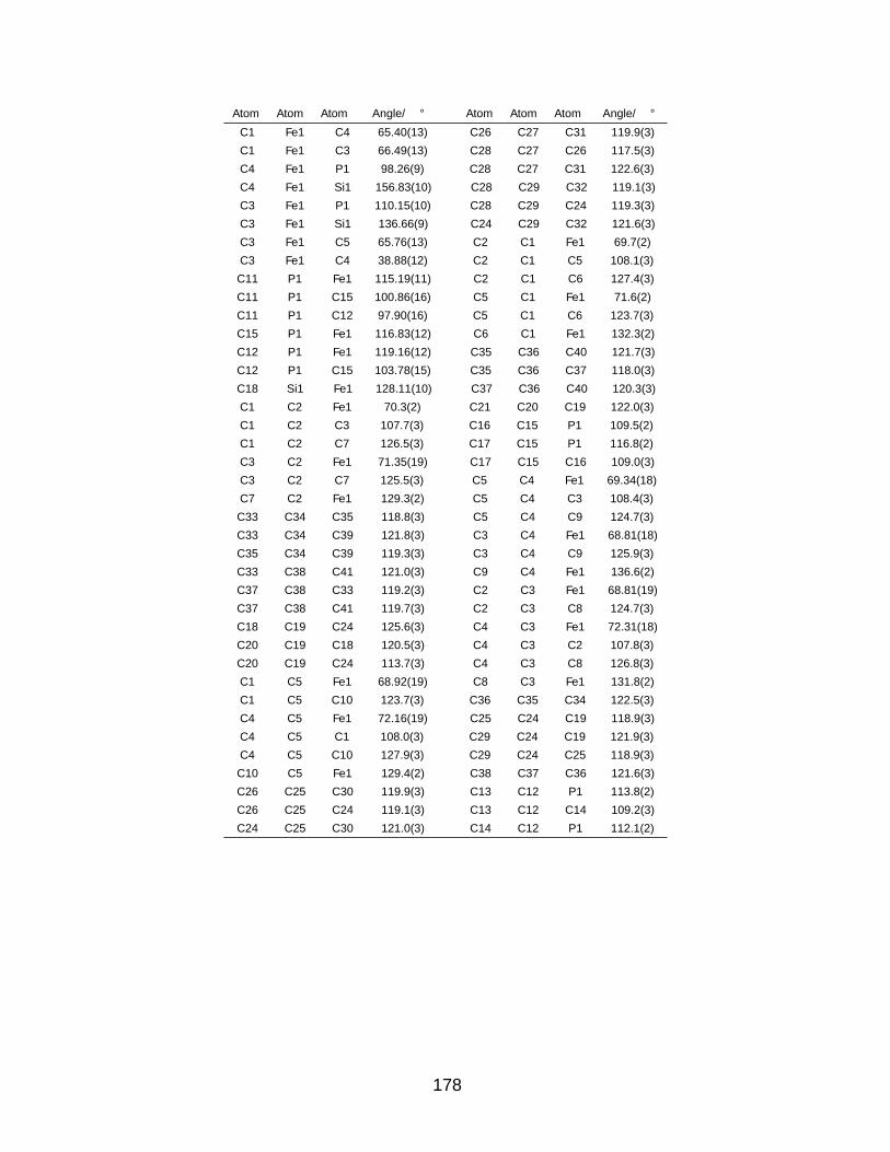
Atom Atom Atom Angle/° Atom Atom Atom Angle/°
C1 Fe1 C4 65.40(13) C26 C27 C31 119.9(3)
C1 Fe1 C3 66.49(13) C28 C27 C26 117.5(3)
C4 Fe1 P1 98.26(9) C28 C27 C31 122.6(3)
C4 Fe1 Si1 156.83(10) C28 C29 C32 119.1(3)
C3 Fe1 P1 110.15(10) C28 C29 C24 119.3(3)
C3 Fe1 Si1 136.66(9) C24 C29 C32 121.6(3)
C3 Fe1 C5 65.76(13) C2 C1 Fe1 69.7(2)
C3 Fe1 C4 38.88(12) C2 C1 C5 108.1(3)
C11 P1 Fe1 115.19(11) C2 C1 C6 127.4(3)
C11 P1 C15 100.86(16) C5 C1 Fe1 71.6(2)
C11 P1 C12 97.90(16) C5 C1 C6 123.7(3)
C15 P1 Fe1 116.83(12) C6 C1 Fe1 132.3(2)
C12 P1 Fe1 119.16(12) C35 C36 C40 121.7(3)
C12 P1 C15 103.78(15) C35 C36 C37 118.0(3)
C18 Si1 Fe1 128.11(10) C37 C36 C40 120.3(3)
C1 C2 Fe1 70.3(2) C21 C20 C19 122.0(3)
C1 C2 C3 107.7(3) C16 C15 P1 109.5(2)
C1 C2 C7 126.5(3) C17 C15 P1 116.8(2)
C3 C2 Fe1 71.35(19) C17 C15 C16 109.0(3)
C3 C2 C7 125.5(3) C5 C4 Fe1 69.34(18)
C7 C2 Fe1 129.3(2) C5 C4 C3 108.4(3)
C33 C34 C35 118.8(3) C5 C4 C9 124.7(3)
C33 C34 C39 121.8(3) C3 C4 Fe1 68.81(18)
C35 C34 C39 119.3(3) C3 C4 C9 125.9(3)
C33 C38 C41 121.0(3) C9 C4 Fe1 136.6(2)
C37 C38 C33 119.2(3) C2 C3 Fe1 68.81(19)
C37 C38 C41 119.7(3) C2 C3 C8 124.7(3)
C18 C19 C24 125.6(3) C4 C3 Fe1 72.31(18)
C20 C19 C18 120.5(3) C4 C3 C2 107.8(3)
C20 C19 C24 113.7(3) C4 C3 C8 126.8(3)
C1 C5 Fe1 68.92(19) C8 C3 Fe1 131.8(2)
C1 C5 C10 123.7(3) C36 C35 C34 122.5(3)
C4 C5 Fe1 72.16(19) C25 C24 C19 118.9(3)
C4 C5 C1 108.0(3) C29 C24 C19 121.9(3)
C4 C5 C10 127.9(3) C29 C24 C25 118.9(3)
C10 C5 Fe1 129.4(2) C38 C37 C36 121.6(3)
C26 C25 C30 119.9(3) C13 C12 P1 113.8(2)
C26 C25 C24 119.1(3) C13 C12 C14 109.2(3)
C24 C25 C30 121.0(3) C14 C12 P1 112.1(2)
178

Compound 2.6
Table A.7: Bond Lengths for 2.6.
Atom Atom Length/A Atom Atom Length/A
Fe1 N1 2.186(2) C1 C5 1.392(16)
Fe1 C1 2.078(9) C8 C3 1.503(12)
Fe1 N2 1.782(8) C3 C2 1.450(13)
Fe1 C3 2.085(8) C3 C4 1.437(12)
Fe1 C2 2.102(9) C2 C7 1.484(13)
Fe1 C5 2.096(9) C15 C17 1.525(12)
Fe1 C4 2.108(9) C15 C16 1.534(12)
N1 C15 1.861(9) C12 C13 1.526(13)
N1 C11 1.845(9) C12 C14 1.526(13)
N1 C12 1.851(9) C5 C4 1.400(14)
N1 N2 1.106(12) C5 C10 1.524(14)
C1 C2 1.440(13) C4 C9 1.502(15)
C1 C6 1.525(15)
Table A.8: Bond Angles for 2.6.
Atom Atom Atom Angle/° Atom Atom Atom Angle/°
C1 Fe1 N1 169.7(3) C5 C1 C6 127.4(9)
C1 Fe1 C3 67.2(4) N1 N2 Fe1 173.3(8)
C1 Fe1 C2 40.3(4) C8 C3 Fe1 132.2(7)
C1 Fe1 C5 38.9(4) C2 C3 Fe1 70.3(5)
C1 Fe1 C4 66.3(4) C2 C3 C8 123.3(8)
N2 Fe1 N1 92.0(3) C4 C3 Fe1 70.8(5)
N2 Fe1 C1 94.7(4) C4 C3 C8 127.9(9)
N2 Fe1 C3 159.8(4) C4 C3 C2 108.1(8)
N2 Fe1 C2 128.5(4) C1 C2 Fe1 69.0(5)
N2 Fe1 C5 94.3(4) C1 C2 C3 105.8(8)
N2 Fe1 C4 125.6(4) C1 C2 C7 128.5(9)
C3 Fe1 N1 104.9(3) C3 C2 Fe1 69.1(5)
C3 Fe1 C2 40.5(3) C3 C2 C7 125.6(8)
C3 Fe1 C5 66.2(4) C7 C2 Fe1 129.4(7)
C3 Fe1 C4 40.1(3) C17 C15 N1 115.0(6)
C2 Fe1 N1 136.8(3) C17 C15 C16 110.5(8)
C2 Fe1 C4 67.4(4) C16 C15 N1 110.2(6)
C5 Fe1 N1 132.7(3) C13 C12 N1 111.6(6)
C5 Fe1 C2 66.5(4) C13 C12 C14 110.8(8)
C5 Fe1 C4 38.9(4) C14 C12 N1 110.9(7)
C4 Fe1 N1 103.5(3) C1 C5 Fe1 69.8(5)
C15 N1 Fe1 113.5(3) C1 C5 C4 110.2(8)
C11 N1 Fe1 119.8(3) C1 C5 C10 124.2(10)
C11 N1 C15 102.5(4) C4 C5 Fe1 71.0(5)
C11 N1 C12 99.9(4) C4 C5 C10 125.7(11)
C12 N1 Fe1 116.4(3) C10 C5 Fe1 127.0(7)
Continued on following page...
179

Atom Atom Atom Angle/° Atom Atom Atom Angle/°
C12 N1 C15 102.2(4) C3 C4 Fe1 69.1(5)
C2 C1 Fe1 70.7(5) C3 C4 C9 126.1(10)
C2 C1 C6 123.8(10) C5 C4 Fe1 70.1(5)
C6 C1 Fe1 126.1(7) C5 C4 C3 107.2(9)
C5 C1 Fe1 71.2(6) C5 C4 C9 126.2(10)
C5 C1 C2 108.7(9) C9 C4 Fe1 132.4(7)
A.2 Crystallographic Data Tables for Chapter 3
Compound 3.1
Table A.9: Bond Lengths for 3.1.
Atom Atom Length/A Atom Atom Length/A
Fe1 C4 2.072(4) C19 C24 1.413(6)
Fe1 C1 2.066(4) C2 C3 1.425(5)
Fe1 C11 2.171(4) C2 C7 1.494(6)
Fe1 C2 2.070(4) C36 C33 1.508(6)
Fe1 C3 2.074(4) C3 C8 1.494(5)
Fe1 C15 2.093(4) C22 C23 1.387(6)
Fe1 C13 2.106(4) C22 C21 1.393(6)
Fe1 C12 2.077(4) C22 C26 1.514(6)
Fe1 C5 2.063(4) C15 C14 1.427(5)
Fe1 C3AA 2.121(4) C15 C18 1.508(5)
Fe1 C14 2.075(4) C20 C21 1.397(6)
Fe2 C28 2.074(4) C20 C25 1.511(7)
Fe2 C11 2.108(4) C13 C12 1.413(6)
Fe2 C19 2.068(4) C13 C14 1.405(6)
C4 C3 1.432(6) C13 C17 1.506(5)
C4 C5 1.434(5) C23 C24 1.392(6)
C4 C9 1.499(5) C30 C29 1.390(6)
C27 C24 1.517(6) C30 C31 1.386(7)
C1 C2 1.428(6) C12 C3AA 1.424(5)
C1 C5 1.429(6) C35 C31 1.511(6)
C1 C6 1.502(5) C32 C33 1.399(6)
C28 C33 1.409(6) C32 C31 1.378(7)
C28 C29 1.415(6) C5 C10 1.494(6)
C11 C15 1.431(6) C3AA C16 1.495(6)
C11 C3AA 1.429(5) C29 C34 1.516(6)
C19 C20 1.412(6)
Table A.10: Bond Angles for 3.1.
Atom Atom Atom Angle/° Atom Atom Atom Angle/°
C4 Fe1 C11 144.67(15) Fe2 C11 Fe1 143.81(18)
C4 Fe1 C3 40.42(16) C15 C11 Fe1 67.5(2)
C4 Fe1 C15 173.65(15) C15 C11 Fe2 123.7(3)
Continued on following page...
180

Atom Atom Atom Angle/° Atom Atom Atom Angle/°
C4 Fe1 C13 111.37(15) C3AA C11 Fe1 68.7(2)
C4 Fe1 C12 101.63(15) C3AA C11 Fe2 119.3(3)
C4 Fe1 C3AA 115.60(15) C3AA C11 C15 116.2(3)
C4 Fe1 C14 140.14(15) C20 C19 Fe2 120.6(3)
C1 Fe1 C4 68.08(14) C20 C19 C24 116.2(4)
C1 Fe1 C11 102.70(14) C24 C19 Fe2 123.2(3)
C1 Fe1 C2 40.38(16) C1 C2 Fe1 69.7(2)
C1 Fe1 C3 67.66(15) C1 C2 C7 126.3(4)
C1 Fe1 C15 107.20(15) C3 C2 Fe1 70.0(2)
C1 Fe1 C13 165.59(17) C3 C2 C1 107.8(4)
C1 Fe1 C12 154.40(16) C3 C2 C7 125.8(4)
C1 Fe1 C3AA 121.98(15) C7 C2 Fe1 129.4(3)
C1 Fe1 C14 132.26(16) C4 C3 Fe1 69.7(2)
C2 Fe1 C4 68.09(15) C4 C3 C8 124.8(3)
C2 Fe1 C11 127.51(15) C2 C3 Fe1 69.8(2)
C2 Fe1 C3 40.22(15) C2 C3 C4 108.5(3)
C2 Fe1 C15 105.56(15) C2 C3 C8 126.5(4)
C2 Fe1 C13 125.36(16) C8 C3 Fe1 129.0(3)
C2 Fe1 C12 159.02(15) C23 C22 C21 117.2(4)
C2 Fe1 C3AA 161.17(15) C23 C22 C26 121.1(4)
C2 Fe1 C14 104.66(16) C21 C22 C26 121.6(4)
C3 Fe1 C11 167.73(15) C11 C15 Fe1 73.4(2)
C3 Fe1 C15 134.44(16) C11 C15 C18 120.2(3)
C3 Fe1 C13 102.18(15) C14 C15 Fe1 69.3(2)
C3 Fe1 C12 120.39(15) C14 C15 C11 121.7(3)
C3 Fe1 C3AA 152.66(15) C14 C15 C18 118.1(4)
C3 Fe1 C14 108.37(16) C18 C15 Fe1 130.9(3)
C15 Fe1 C11 39.15(15) C19 C20 C25 120.5(4)
C15 Fe1 C13 72.07(14) C21 C20 C19 121.0(4)
C15 Fe1 C3AA 70.34(15) C21 C20 C25 118.4(4)
C13 Fe1 C11 85.80(14) C12 C13 Fe1 69.1(2)
C13 Fe1 C3AA 71.80(15) C12 C13 C17 120.9(4)
C12 Fe1 C11 71.62(14) C14 C13 Fe1 69.1(2)
C12 Fe1 C15 84.41(15) C14 C13 C12 117.4(3)
C12 Fe1 C13 39.48(16) C14 C13 C17 121.7(4)
C12 Fe1 C3AA 39.63(14) C17 C13 Fe1 133.3(3)
C5 Fe1 C4 40.58(14) C22 C23 C24 121.7(4)
C5 Fe1 C1 40.48(15) C19 C24 C27 120.2(4)
C5 Fe1 C11 110.19(14) C23 C24 C27 118.1(4)
C5 Fe1 C2 68.09(16) C23 C24 C19 121.7(4)
C5 Fe1 C3 67.90(15) C31 C30 C29 121.5(4)
C5 Fe1 C15 137.98(15) C13 C12 Fe1 71.4(2)
C5 Fe1 C13 146.86(16) C13 C12 C3AA 121.8(3)
C5 Fe1 C12 116.69(16) C3AA C12 Fe1 71.9(2)
C5 Fe1 C3AA 102.10(15) C31 C32 C33 121.8(4)
C5 Fe1 C14 172.38(17) C4 C5 Fe1 70.0(2)
C3AA Fe1 C11 38.87(14) C4 C5 C10 126.0(4)
C14 Fe1 C11 71.95(15) C1 C5 Fe1 69.9(2)
C14 Fe1 C15 40.04(14) C1 C5 C4 108.0(3)
C14 Fe1 C13 39.26(15) C1 C5 C10 125.9(3)
Continued on following page...
181

Atom Atom Atom Angle/° Atom Atom Atom Angle/°
C14 Fe1 C12 70.91(16) C10 C5 Fe1 128.1(3)
C14 Fe1 C3AA 84.15(15) C22 C21 C20 122.0(4)
C28 Fe2 C11 129.87(15) C28 C33 C36 121.7(3)
C19 Fe2 C28 118.30(15) C32 C33 C28 121.0(4)
C19 Fe2 C11 111.32(15) C32 C33 C36 117.3(4)
C3 C4 Fe1 69.8(2) C11 C3AA Fe1 72.4(2)
C3 C4 C5 107.4(3) C11 C3AA C16 120.1(3)
C3 C4 C9 125.3(3) C12 C3AA Fe1 68.5(2)
C5 C4 Fe1 69.4(2) C12 C3AA C11 121.3(4)
C5 C4 C9 127.3(4) C12 C3AA C16 118.6(3)
C9 C4 Fe1 126.9(3) C16 C3AA Fe1 133.5(3)
C2 C1 Fe1 70.0(2) C15 C14 Fe1 70.7(2)
C2 C1 C5 108.2(3) C13 C14 Fe1 71.6(2)
C2 C1 C6 125.4(4) C13 C14 C15 121.5(4)
C5 C1 Fe1 69.6(2) C28 C29 C34 120.8(4)
C5 C1 C6 126.3(4) C30 C29 C28 121.4(4)
C6 C1 Fe1 128.9(3) C30 C29 C34 117.7(4)
C33 C28 Fe2 125.1(3) C30 C31 C35 120.0(4)
C33 C28 C29 116.3(3) C32 C31 C30 117.9(4)
C29 C28 Fe2 118.6(3) C32 C31 C35 122.1(5)
Compound 3.2a
Table A.11: Bond Lengths for 3.2a.
Atom Atom Length/A Atom Atom Length/A
Fe1 P1 2.2644(5) C4 C5 1.418(2)
Fe1 C1 2.2393(15) C4 C9 1.506(2)
Fe1 C2 2.2229(16) C5 C10 1.499(2)
Fe1 C3 2.1240(17) C11 C12 1.529(2)
Fe1 C4 2.1222(16) C11 C13 1.528(2)
Fe1 C5 2.2099(15) C15 C16 1.527(2)
Fe1 C18 1.9872(15) C15 C17 1.527(2)
P1 C11 1.8633(16) C18 C19 1.416(2)
P1 C14 1.8332(16) C18 C23 1.415(2)
P1 C15 1.8576(16) C19 C20 1.396(2)
C1 C2 1.421(2) C19 C24 1.514(2)
C1 C5 1.422(2) C20 C21 1.387(2)
C1 C6 1.504(2) C21 C22 1.387(2)
C2 C3 1.420(2) C21 C25 1.512(2)
C2 C7 1.505(2) C22 C23 1.396(2)
C3 C4 1.440(2) C23 C26 1.516(2)
C3 C8 1.499(2)
Continued on following page...
182
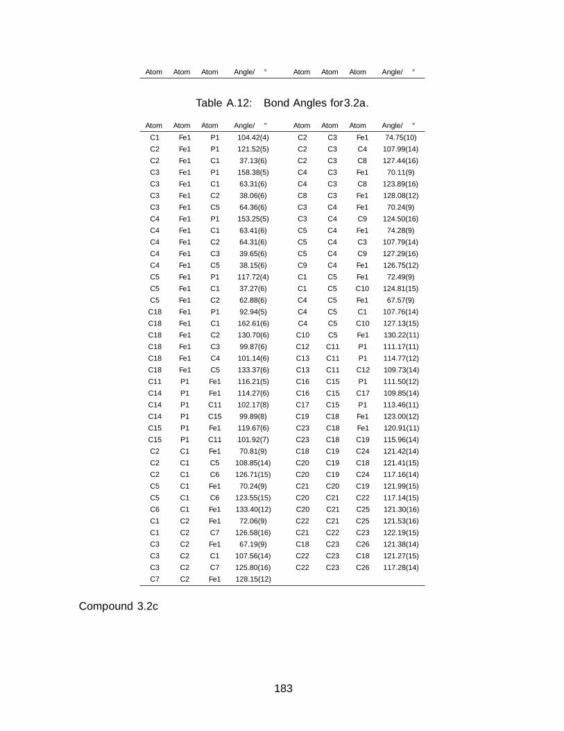
Atom Atom Atom Angle/° Atom Atom Atom Angle/°
Table A.12: Bond Angles for 3.2a.
Atom Atom Atom Angle/° Atom Atom Atom Angle/°
C1 Fe1 P1 104.42(4) C2 C3 Fe1 74.75(10)
C2 Fe1 P1 121.52(5) C2 C3 C4 107.99(14)
C2 Fe1 C1 37.13(6) C2 C3 C8 127.44(16)
C3 Fe1 P1 158.38(5) C4 C3 Fe1 70.11(9)
C3 Fe1 C1 63.31(6) C4 C3 C8 123.89(16)
C3 Fe1 C2 38.06(6) C8 C3 Fe1 128.08(12)
C3 Fe1 C5 64.36(6) C3 C4 Fe1 70.24(9)
C4 Fe1 P1 153.25(5) C3 C4 C9 124.50(16)
C4 Fe1 C1 63.41(6) C5 C4 Fe1 74.28(9)
C4 Fe1 C2 64.31(6) C5 C4 C3 107.79(14)
C4 Fe1 C3 39.65(6) C5 C4 C9 127.29(16)
C4 Fe1 C5 38.15(6) C9 C4 Fe1 126.75(12)
C5 Fe1 P1 117.72(4) C1 C5 Fe1 72.49(9)
C5 Fe1 C1 37.27(6) C1 C5 C10 124.81(15)
C5 Fe1 C2 62.88(6) C4 C5 Fe1 67.57(9)
C18 Fe1 P1 92.94(5) C4 C5 C1 107.76(14)
C18 Fe1 C1 162.61(6) C4 C5 C10 127.13(15)
C18 Fe1 C2 130.70(6) C10 C5 Fe1 130.22(11)
C18 Fe1 C3 99.87(6) C12 C11 P1 111.17(11)
C18 Fe1 C4 101.14(6) C13 C11 P1 114.77(12)
C18 Fe1 C5 133.37(6) C13 C11 C12 109.73(14)
C11 P1 Fe1 116.21(5) C16 C15 P1 111.50(12)
C14 P1 Fe1 114.27(6) C16 C15 C17 109.85(14)
C14 P1 C11 102.17(8) C17 C15 P1 113.46(11)
C14 P1 C15 99.89(8) C19 C18 Fe1 123.00(12)
C15 P1 Fe1 119.67(6) C23 C18 Fe1 120.91(11)
C15 P1 C11 101.92(7) C23 C18 C19 115.96(14)
C2 C1 Fe1 70.81(9) C18 C19 C24 121.42(14)
C2 C1 C5 108.85(14) C20 C19 C18 121.41(15)
C2 C1 C6 126.71(15) C20 C19 C24 117.16(14)
C5 C1 Fe1 70.24(9) C21 C20 C19 121.99(15)
C5 C1 C6 123.55(15) C20 C21 C22 117.14(15)
C6 C1 Fe1 133.40(12) C20 C21 C25 121.30(16)
C1 C2 Fe1 72.06(9) C22 C21 C25 121.53(16)
C1 C2 C7 126.58(16) C21 C22 C23 122.19(15)
C3 C2 Fe1 67.19(9) C18 C23 C26 121.38(14)
C3 C2 C1 107.56(14) C22 C23 C18 121.27(15)
C3 C2 C7 125.80(16) C22 C23 C26 117.28(14)
C7 C2 Fe1 128.15(12)
Compound 3.2c
183

Table A.13: Bond Lengths for 3.2c.
Atom Atom Length/A Atom Atom Length/A
Fe1 P1 2.2360(5) C22 C21 1.386(3)
Fe1 C4 2.1306(17) C25 C30 1.395(2)
Fe1 C3 2.1119(17) C25 C26 1.392(2)
Fe1 C37 1.9743(16) C36 C35 1.386(3)
Fe1 C5 2.2349(17) C41 C42 1.391(2)
Fe1 C2 2.2056(17) C41 C40 1.393(3)
Fe1 C1 2.2341(17) C12 C13 1.392(3)
P1 C17 1.8304(17) C42 C45 1.507(2)
P1 C11 1.8312(17) C30 C29 1.384(3)
P1 C23 1.8451(16) C16 C15 1.388(3)
N1 C31 1.8345(17) C18 C19 1.391(3)
P2 C25 1.8291(17) C38 C39 1.396(2)
P2 C24 1.8545(17) C38 C43 1.506(2)
C32 C31 1.393(2) C2 C1 1.424(3)
C32 C33 1.389(3) C2 C7 1.504(3)
C17 C22 1.395(2) C39 C40 1.377(3)
C17 C18 1.393(2) C23 C24 1.527(2)
C11 C12 1.388(2) C34 C33 1.383(3)
C11 C16 1.395(2) C34 C35 1.384(3)
C31 C36 1.394(2) C21 C20 1.382(3)
C4 C3 1.442(2) C40 C44 1.507(2)
C4 C5 1.418(2) C20 C19 1.384(3)
C4 C9 1.496(2) C29 C28 1.385(3)
C3 C2 1.415(3) C26 C27 1.390(3)
C3 C8 1.498(3) C27 C28 1.381(3)
C37 C42 1.415(2) C1 C6 1.499(2)
C37 C38 1.410(2) C13 C14 1.380(3)
C5 C10 1.503(2) C15 C14 1.380(3)
C5 C1 1.423(3)
Table A.14: Bond Angles for 3.2c.
Atom Atom Atom Angle/° Atom Atom Atom Angle/°
C4 Fe1 P1 157.77(5) C38 C37 C42 116.54(15)
C4 Fe1 C5 37.83(6) C4 C5 Fe1 67.10(9)
C4 Fe1 C2 64.43(7) C4 C5 C10 126.25(16)
C4 Fe1 C1 63.34(6) C4 C5 C1 107.64(16)
C3 Fe1 P1 150.63(5) C10 C5 Fe1 130.29(12)
C3 Fe1 C4 39.73(7) C1 C5 Fe1 71.40(10)
C3 Fe1 C5 64.17(7) C1 C5 C10 125.96(16)
C3 Fe1 C2 38.19(7) C21 C22 C17 120.89(17)
C3 Fe1 C1 63.55(7) C30 C25 P2 116.61(13)
C37 Fe1 P1 99.00(5) C26 C25 P2 124.71(13)
C37 Fe1 C4 96.44(7) C26 C25 C30 118.68(16)
C37 Fe1 C3 98.07(7) C35 C36 C31 120.85(16)
C37 Fe1 C5 127.72(7) C42 C41 C40 121.43(16)
Continued on following page...
184

Atom Atom Atom Angle/° Atom Atom Atom Angle/°
C37 Fe1 C2 131.23(7) C11 C12 C13 120.55(17)
C37 Fe1 C1 159.18(7) C37 C42 C45 120.61(15)
C5 Fe1 P1 120.49(5) C41 C42 C37 121.23(16)
C2 Fe1 P1 114.76(5) C41 C42 C45 118.11(15)
C2 Fe1 C5 62.82(7) C29 C30 C25 120.67(17)
C2 Fe1 C1 37.40(7) C15 C16 C11 120.28(17)
C1 Fe1 P1 101.80(5) C19 C18 C17 120.17(17)
C1 Fe1 C5 37.13(6) C37 C38 C43 121.38(15)
C17 P1 Fe1 112.78(5) C39 C38 C37 120.78(16)
C17 P1 C11 103.92(8) C39 C38 C43 117.82(15)
C17 P1 C23 99.90(7) C3 C2 Fe1 67.32(9)
C11 P1 Fe1 117.05(6) C3 C2 C1 107.61(16)
C11 P1 C23 101.43(8) C3 C2 C7 125.55(18)
C23 P1 Fe1 119.30(6) C1 C2 Fe1 72.39(10)
C31 P2 C24 100.78(7) C1 C2 C7 126.61(17)
C25 P2 C31 101.12(8) C7 C2 Fe1 129.85(13)
C25 P2 C24 102.67(8) C40 C39 C38 122.15(16)
C33 C32 C31 120.24(17) C24 C23 P1 113.87(11)
C22 C17 P1 117.42(13) C33 C34 C35 119.74(17)
C18 C17 P1 123.55(13) C20 C21 C22 119.93(17)
C18 C17 C22 118.74(16) C41 C40 C44 120.00(17)
C12 C11 P1 119.08(13) C39 C40 C41 117.73(16)
C12 C11 C16 118.94(16) C39 C40 C44 122.27(17)
C16 C11 P1 121.95(13) C21 C20 C19 119.90(17)
C32 C31 P2 124.24(13) C34 C33 C32 120.48(17)
C32 C31 C36 118.69(16) C20 C19 C18 120.37(17)
C36 C31 P2 117.06(13) C30 C29 C28 120.28(17)
C3 C4 Fe1 69.43(9) C23 C24 P2 111.21(11)
C3 C4 C9 124.24(16) C27 C26 C25 120.38(17)
C5 C4 Fe1 75.07(10) C34 C35 C36 119.94(17)
C5 C4 C3 107.80(15) C28 C27 C26 120.43(18)
C5 C4 C9 127.19(16) C5 C1 Fe1 71.47(10)
C9 C4 Fe1 128.80(12) C5 C1 C2 108.80(16)
C4 C3 Fe1 70.83(9) C5 C1 C6 125.08(17)
C4 C3 C8 124.67(16) C2 C1 Fe1 70.22(10)
C2 C3 Fe1 74.49(10) C2 C1 C6 125.60(17)
C2 C3 C4 108.07(15) C6 C1 Fe1 130.80(12)
C2 C3 C8 126.62(17) C14 C13 C12 119.88(18)
C8 C3 Fe1 127.53(13) C27 C28 C29 119.55(17)
C42 C37 Fe1 121.53(12) C14 C15 C16 120.18(18)
C38 C37 Fe1 121.64(13) C15 C14 C13 120.15(17)
A.3 Crystallographic Data Tables for Chapter 4
Compound 4.1
185

Table A.15: Bond Lengths for 4.1.
Atom Atom Length/A Atom Atom Length/A
Fe1 P1 2.2626(5) C1 C6 1.498(2)
Fe1 Si1 2.3414(5) C18 C23 1.403(2)
Fe1 N1 1.7866(12) C18 C19 1.399(2)
Fe1 C2 2.1242(14) C24 C29 1.402(2)
Fe1 C1 2.1727(14) C15 C17 1.530(2)
Fe1 C5 2.1463(14) C15 C16 1.530(2)
Fe1 C4 2.1123(14) C5 C4 1.429(2)
Fe1 C3 2.1300(14) C5 C10 1.505(2)
P1 C11 1.8362(14) C4 C3 1.421(2)
P1 C15 1.8717(15) C4 C9 1.502(2)
P1 C12 1.8671(15) C23 C22 1.388(2)
Si1 C18 1.9074(15) C3 C8 1.503(2)
Si1 C24 1.9171(15) C19 C20 1.392(2)
N1 N2 1.1248(17) C12 C13 1.524(2)
C2 C1 1.441(2) C12 C14 1.525(2)
C2 C7 1.503(2) C26 C27 1.386(2)
C2 C3 1.431(2) C22 C21 1.385(2)
C25 C24 1.401(2) C29 C28 1.392(2)
C25 C26 1.389(2) C27 C28 1.381(2)
C1 C5 1.411(2) C20 C21 1.387(2)
Table A.16: Bond Angles for 4.1.
Atom Atom Atom Angle/° Atom Atom Atom Angle/°
P1 Fe1 Si1 97.248(15) C2 C1 Fe1 68.60(8)
N1 Fe1 P1 89.83(4) C2 C1 C6 126.42(13)
N1 Fe1 Si1 89.96(4) C5 C1 Fe1 69.92(8)
N1 Fe1 C2 157.32(6) C5 C1 C2 108.20(13)
N1 Fe1 C1 128.25(5) C5 C1 C6 124.22(13)
N1 Fe1 C5 94.65(5) C6 C1 Fe1 136.79(10)
N1 Fe1 C4 91.91(6) C23 C18 Si1 121.15(11)
N1 Fe1 C3 123.80(6) C19 C18 Si1 121.74(11)
C2 Fe1 P1 108.57(4) C19 C18 C23 117.03(13)
C2 Fe1 Si1 100.40(4) C25 C24 Si1 122.91(11)
C2 Fe1 C1 39.17(5) C25 C24 C29 116.43(14)
C2 Fe1 C5 65.50(5) C29 C24 Si1 120.23(11)
C2 Fe1 C3 39.31(6) C17 C15 P1 114.42(10)
C1 Fe1 P1 95.85(4) C16 C15 P1 111.19(10)
C1 Fe1 Si1 139.51(4) C16 C15 C17 108.97(12)
C5 Fe1 P1 117.05(4) C1 C5 Fe1 71.95(8)
C5 Fe1 Si1 145.35(4) C1 C5 C4 108.04(13)
C5 Fe1 C1 38.13(5) C1 C5 C10 126.90(14)
C4 Fe1 P1 156.24(4) C4 C5 Fe1 69.12(8)
C4 Fe1 Si1 106.44(4) C4 C5 C10 124.79(14)
C4 Fe1 C2 65.88(6) C10 C5 Fe1 129.18(10)
C4 Fe1 C1 64.84(6) C5 C4 Fe1 71.69(8)
Continued on following page...
186

Atom Atom Atom Angle/° Atom Atom Atom Angle/°
C4 Fe1 C5 39.19(6) C5 C4 C9 125.10(14)
C4 Fe1 C3 39.15(6) C3 C4 Fe1 71.10(8)
C3 Fe1 P1 146.36(4) C3 C4 C5 108.45(13)
C3 Fe1 Si1 83.52(4) C3 C4 C9 126.20(14)
C3 Fe1 C1 65.10(5) C9 C4 Fe1 127.53(10)
C3 Fe1 C5 65.47(5) C22 C23 C18 121.51(14)
C11 P1 Fe1 114.28(5) C2 C3 Fe1 70.13(8)
C11 P1 C15 99.16(7) C2 C3 C8 124.50(13)
C11 P1 C12 98.91(7) C4 C3 Fe1 69.75(8)
C15 P1 Fe1 114.03(5) C4 C3 C2 107.74(13)
C12 P1 Fe1 125.30(5) C4 C3 C8 126.32(14)
C12 P1 C15 101.11(7) C8 C3 Fe1 136.24(10)
C18 Si1 Fe1 121.84(5) C20 C19 C18 121.59(14)
C18 Si1 C24 97.97(6) C13 C12 P1 111.77(11)
C24 Si1 Fe1 115.92(5) C13 C12 C14 110.14(13)
N2 N1 Fe1 175.24(12) C14 C12 P1 116.00(11)
C1 C2 Fe1 72.23(8) C27 C26 C25 120.01(15)
C1 C2 C7 127.48(13) C21 C22 C23 120.00(15)
C7 C2 Fe1 132.69(10) C28 C29 C24 121.62(14)
C3 C2 Fe1 70.56(8) C28 C27 C26 119.27(15)
C3 C2 C1 107.46(12) C21 C20 C19 119.75(15)
C3 C2 C7 123.76(13) C22 C21 C20 119.82(14)
C26 C25 C24 122.15(14) C27 C28 C29 120.50(15)
Compound 4.3
Table A.17: Bond Lengths for 4.3.
Atom Atom Length/A Atom Atom Length/A
Fe1 P1 2.2469(15) Fe2 P2 2.2361(14)
Fe1 Si1 2.3346(15) Fe2 Si2 2.3436(16)
Fe1 N1 1.774(5) Fe2 N3 1.770(5)
Fe1 C1 2.164(5) Fe2 C33 2.149(5)
Fe1 C2 2.135(5) Fe2 C34 2.125(5)
Fe1 C3 2.099(5) Fe2 C35 2.112(5)
Fe1 C4 2.130(5) Fe2 C36 2.125(5)
Fe1 C5 2.130(5) Fe2 C37 2.127(5)
P1 C11 1.872(7) P2 C43 1.885(5)
P1 C14 1.833(6) P2 C46 1.840(6)
P1 C15 1.855(5) P2 C47 1.854(5)
Si1 C18 1.924(5) Si2 C50 1.924(5)
N1 N2 1.133(6) N3 N4 1.134(6)
C1 C2 1.414(8) C33 C34 1.402(7)
C1 C5 1.423(7) C33 C37 1.442(7)
C1 C6 1.485(8) C33 C38 1.492(7)
C2 C3 1.452(7) C34 C35 1.432(7)
C2 C7 1.490(8) C34 C39 1.506(7)
C3 C4 1.401(8) C35 C36 1.428(7)
C3 C8 1.506(8) C35 C40 1.487(7)
Continued on following page...
187

Atom Atom Length/A Atom Atom Length/A
C4 C5 1.429(7) C36 C37 1.424(7)
C4 C9 1.499(7) C36 C41 1.490(7)
C5 C10 1.505(7) C37 C42 1.495(7)
C11 C12 1.572(10) C43 C44 1.528(8)
C11 C13 1.388(10) C43 C45 1.527(8)
C15 C16 1.542(8) C47 C48 1.539(7)
C15 C17 1.513(10) C47 C49 1.527(8)
C18 C19 1.408(7) C50 C51 1.407(7)
C18 C23 1.409(7) C50 C55 1.415(7)
C19 C20 1.411(7) C51 C52 1.410(7)
C19 C24 1.508(7) C51 C56 1.533(7)
C20 C21 1.377(7) C52 C53 1.385(7)
C21 C22 1.399(7) C53 C54 1.385(7)
C21 C27 1.531(7) C53 C59 1.528(7)
C22 C23 1.403(7) C54 C55 1.386(7)
C23 C30 1.507(7) C55 C62 1.530(7)
C24 C25 1.527(8) C56 C57 1.543(7)
C24 C26 1.543(7) C56 C58 1.526(7)
C27 C28 1.528(8) C59 C60 1.532(7)
C27 C29 1.500(8) C59 C61 1.513(7)
C30 C31 1.529(7) C62 C63 1.538(7)
C30 C32 1.538(7) C62 C64 1.537(7)
Table A.18: Bond Angles for 4.3.
Atom Atom Atom Angle/° Atom Atom Atom Angle/°
P1 Fe1 Si1 86.53(5) P2 Fe2 Si2 84.62(6)
N1 Fe1 P1 90.78(14) N3 Fe2 P2 92.15(14)
N1 Fe1 Si1 87.09(16) N3 Fe2 Si2 87.92(16)
N1 Fe1 C1 130.7(2) N3 Fe2 C33 126.1(2)
N1 Fe1 C2 95.4(2) N3 Fe2 C34 92.6(2)
N1 Fe1 C3 90.4(2) N3 Fe2 C35 90.2(2)
N1 Fe1 C4 120.6(2) N3 Fe2 C36 123.25(19)
N1 Fe1 C5 155.7(2) N3 Fe2 C37 155.5(2)
C1 Fe1 P1 96.85(15) C33 Fe2 P2 98.52(14)
C1 Fe1 Si1 141.82(17) C33 Fe2 Si2 145.41(15)
C2 Fe1 P1 116.41(16) C34 Fe2 P2 121.95(14)
C2 Fe1 Si1 156.83(15) C34 Fe2 Si2 153.36(14)
C2 Fe1 C1 38.4(2) C34 Fe2 C33 38.3(2)
C3 Fe1 P1 156.44(16) C34 Fe2 C37 65.5(2)
C3 Fe1 Si1 117.03(16) C35 Fe2 P2 161.42(14)
C3 Fe1 C1 65.1(2) C35 Fe2 Si2 113.89(14)
C3 Fe1 C2 40.1(2) C35 Fe2 C33 65.6(2)
C3 Fe1 C4 38.7(2) C35 Fe2 C34 39.50(18)
C3 Fe1 C5 65.3(2) C35 Fe2 C36 39.40(19)
C4 Fe1 P1 148.53(16) C35 Fe2 C37 66.1(2)
C4 Fe1 Si1 92.84(15) C36 Fe2 P2 144.36(14)
C4 Fe1 C1 65.1(2) C36 Fe2 Si2 92.00(15)
Continued on following page...
188

Atom Atom Atom Angle/° Atom Atom Atom Angle/°
C4 Fe1 C2 66.1(2) C36 Fe2 C33 65.54(19)
C5 Fe1 P1 110.80(14) C36 Fe2 C34 65.6(2)
C5 Fe1 Si1 104.76(15) C36 Fe2 C37 39.14(18)
C5 Fe1 C1 38.7(2) C37 Fe2 P2 108.36(15)
C5 Fe1 C2 65.4(2) C37 Fe2 Si2 106.79(15)
C5 Fe1 C4 39.20(19) C37 Fe2 C33 39.42(19)
C11 P1 Fe1 118.2(3) C43 P2 Fe2 115.43(18)
C14 P1 Fe1 112.67(19) C46 P2 Fe2 112.91(19)
C14 P1 C11 103.0(3) C46 P2 C43 104.8(3)
C14 P1 C15 101.0(3) C46 P2 C47 99.7(3)
C15 P1 Fe1 114.3(2) C47 P2 Fe2 116.50(17)
C15 P1 C11 105.7(4) C47 P2 C43 105.8(3)
C18 Si1 Fe1 127.32(15) C50 Si2 Fe2 131.46(15)
N2 N1 Fe1 176.2(5) N4 N3 Fe2 175.2(5)
C2 C1 Fe1 69.7(3) C34 C33 Fe2 69.9(3)
C2 C1 C5 108.7(5) C34 C33 C37 107.9(4)
C2 C1 C6 123.6(6) C34 C33 C38 125.9(5)
C5 C1 Fe1 69.3(3) C37 C33 Fe2 69.5(3)
C5 C1 C6 126.9(6) C37 C33 C38 124.9(5)
C6 C1 Fe1 135.4(4) C38 C33 Fe2 136.2(4)
C1 C2 Fe1 71.9(3) C33 C34 Fe2 71.8(3)
C1 C2 C3 106.4(5) C33 C34 C35 109.0(5)
C1 C2 C7 129.0(6) C33 C34 C39 126.3(5)
C3 C2 Fe1 68.6(3) C35 C34 Fe2 69.7(3)
C3 C2 C7 124.0(6) C35 C34 C39 124.2(5)
C7 C2 Fe1 130.5(4) C39 C34 Fe2 131.0(4)
C2 C3 Fe1 71.3(3) C34 C35 Fe2 70.8(3)
C2 C3 C8 123.9(5) C34 C35 C40 126.5(5)
C4 C3 Fe1 71.9(3) C36 C35 Fe2 70.8(3)
C4 C3 C2 109.2(5) C36 C35 C34 107.3(5)
C4 C3 C8 126.7(5) C36 C35 C40 126.1(5)
C8 C3 Fe1 126.9(4) C40 C35 Fe2 126.2(4)
C3 C4 Fe1 69.4(3) C35 C36 Fe2 69.8(3)
C3 C4 C5 107.4(5) C35 C36 C41 123.7(4)
C3 C4 C9 125.8(5) C37 C36 Fe2 70.5(3)
C5 C4 Fe1 70.4(3) C37 C36 C35 108.2(4)
C5 C4 C9 125.6(5) C37 C36 C41 127.2(5)
C9 C4 Fe1 135.2(4) C41 C36 Fe2 133.7(4)
C1 C5 Fe1 72.0(3) C33 C37 Fe2 71.1(3)
C1 C5 C4 108.3(5) C33 C37 C42 125.9(5)
C1 C5 C10 125.5(5) C36 C37 Fe2 70.3(3)
C4 C5 Fe1 70.4(3) C36 C37 C33 107.6(5)
C4 C5 C10 124.3(5) C36 C37 C42 125.1(5)
C10 C5 Fe1 135.7(4) C42 C37 Fe2 134.6(4)
C12 C11 P1 113.8(6) C44 C43 P2 114.0(4)
C13 C11 P1 119.2(7) C45 C43 P2 114.4(4)
C13 C11 C12 111.2(6) C45 C43 C44 110.2(5)
C16 C15 P1 117.2(4) C48 C47 P2 115.5(4)
C17 C15 P1 110.5(4) C49 C47 P2 111.0(4)
C17 C15 C16 107.8(5) C49 C47 C48 109.4(5)
Continued on following page...
189

Atom Atom Atom Angle/° Atom Atom Atom Angle/°
C19 C18 Si1 119.7(4) C51 C50 Si2 120.8(4)
C19 C18 C23 118.2(4) C51 C50 C55 117.8(4)
C23 C18 Si1 121.7(4) C55 C50 Si2 120.5(4)
C18 C19 C20 119.5(5) C50 C51 C52 120.2(5)
C18 C19 C24 122.2(4) C50 C51 C56 122.2(5)
C20 C19 C24 118.3(5) C52 C51 C56 117.6(5)
C21 C20 C19 122.8(5) C53 C52 C51 121.6(5)
C20 C21 C22 117.1(5) C52 C53 C59 123.1(5)
C20 C21 C27 118.7(5) C54 C53 C52 117.3(5)
C22 C21 C27 124.0(5) C54 C53 C59 119.6(5)
C21 C22 C23 122.1(5) C53 C54 C55 123.1(5)
C18 C23 C30 121.7(4) C50 C55 C62 120.5(4)
C22 C23 C18 119.9(5) C54 C55 C50 119.7(5)
C22 C23 C30 118.3(5) C54 C55 C62 119.8(5)
C19 C24 C25 111.8(5) C51 C56 C57 110.2(4)
C19 C24 C26 113.1(4) C58 C56 C51 112.3(4)
C25 C24 C26 109.5(4) C58 C56 C57 111.9(4)
C28 C27 C21 110.6(4) C53 C59 C60 110.1(4)
C29 C27 C21 114.7(5) C61 C59 C53 114.4(4)
C29 C27 C28 110.0(5) C61 C59 C60 109.7(5)
C23 C30 C31 111.7(4) C55 C62 C63 111.9(4)
C23 C30 C32 113.7(4) C55 C62 C64 112.3(4)
C31 C30 C32 110.1(5) C64 C62 C63 110.0(4)
Compound 4.4
Table A.19: Bond Lengths for 4.4.
Atom Atom Length/A Atom Atom Length/A
Fe1 P1 2.1887(11) C5 C10 1.493(6)
Fe1 Si1 2.1287(12) C12 C13 1.527(6)
Fe1 C1 2.108(4) C12 C14 1.529(5)
Fe1 C2 2.104(4) C15 C16 1.514(6)
Fe1 C3 2.092(4) C15 C17 1.523(6)
Fe1 C4 2.095(4) C18 C19 1.405(5)
Fe1 C5 2.079(4) C18 C23 1.409(5)
P1 C11 1.846(4) C19 C20 1.390(6)
P1 C12 1.865(4) C19 C24 1.524(5)
P1 C15 1.875(4) C20 C21 1.394(6)
Si1 C18 1.897(4) C21 C22 1.381(6)
C1 C2 1.437(5) C21 C27 1.516(5)
C1 C5 1.426(6) C22 C23 1.392(6)
C1 C6 1.497(6) C23 C30 1.527(5)
C2 C3 1.416(6) C24 C25 1.530(6)
C2 C7 1.492(6) C24 C26 1.536(6)
C3 C4 1.427(6) C27 C28 1.523(7)
C3 C8 1.501(6) C27 C29 1.532(7)
C4 C5 1.435(6) C30 C31 1.532(6)
C4 C9 1.492(6) C30 C32 1.530(6)
190

Table A.20: Bond Angles for 4.4.
Atom Atom Atom Angle/° Atom Atom Atom Angle/°
Si1 Fe1 P1 91.95(4) C4 C3 C8 125.8(4)
C1 Fe1 P1 103.36(11) C8 C3 Fe1 129.8(3)
C1 Fe1 Si1 159.80(11) C3 C4 Fe1 70.0(2)
C2 Fe1 P1 100.59(11) C3 C4 C5 107.1(3)
C2 Fe1 Si1 149.95(12) C3 C4 C9 126.5(4)
C2 Fe1 C1 39.90(15) C5 C4 Fe1 69.3(2)
C3 Fe1 P1 129.80(12) C5 C4 C9 125.9(4)
C3 Fe1 Si1 113.11(11) C9 C4 Fe1 132.3(3)
C3 Fe1 C1 66.70(15) C1 C5 Fe1 71.2(2)
C3 Fe1 C2 39.44(16) C1 C5 C4 108.6(3)
C3 Fe1 C4 39.86(16) C1 C5 C10 125.6(4)
C4 Fe1 P1 167.46(12) C4 C5 Fe1 70.5(2)
C4 Fe1 Si1 99.30(12) C4 C5 C10 125.7(4)
C4 Fe1 C1 67.13(15) C10 C5 Fe1 126.6(3)
C4 Fe1 C2 66.86(16) C13 C12 P1 109.1(3)
C5 Fe1 P1 136.10(12) C13 C12 C14 110.1(3)
C5 Fe1 Si1 120.33(11) C14 C12 P1 115.6(3)
C5 Fe1 C1 39.81(16) C16 C15 P1 115.6(3)
C5 Fe1 C2 66.93(15) C16 C15 C17 110.0(4)
C5 Fe1 C3 66.97(15) C17 C15 P1 108.6(3)
C5 Fe1 C4 40.21(16) C19 C18 Si1 120.7(3)
C11 P1 Fe1 118.66(14) C19 C18 C23 118.8(3)
C11 P1 C12 100.09(19) C23 C18 Si1 120.5(3)
C11 P1 C15 97.23(19) C18 C19 C24 120.0(3)
C12 P1 Fe1 114.18(13) C20 C19 C18 119.9(3)
C12 P1 C15 104.36(19) C20 C19 C24 120.1(3)
C15 P1 Fe1 119.25(13) C19 C20 C21 121.5(3)
C18 Si1 Fe1 130.12(12) C20 C21 C27 121.0(3)
C2 C1 Fe1 69.9(2) C22 C21 C20 118.3(3)
C2 C1 C6 128.2(4) C22 C21 C27 120.8(4)
C5 C1 Fe1 69.0(2) C21 C22 C23 121.9(4)
C5 C1 C2 107.4(3) C18 C23 C30 121.1(3)
C5 C1 C6 123.8(4) C22 C23 C18 119.6(3)
C6 C1 Fe1 133.3(3) C22 C23 C30 119.3(3)
C1 C2 Fe1 70.2(2) C19 C24 C25 110.7(3)
C1 C2 C7 126.9(4) C19 C24 C26 114.4(3)
C3 C2 Fe1 69.8(2) C25 C24 C26 109.5(4)
C3 C2 C1 108.0(3) C21 C27 C28 111.3(4)
C3 C2 C7 124.1(4) C21 C27 C29 110.8(4)
C7 C2 Fe1 134.3(3) C28 C27 C29 111.4(4)
C2 C3 Fe1 70.7(2) C23 C30 C31 109.9(3)
C2 C3 C4 108.9(3) C23 C30 C32 112.5(3)
C2 C3 C8 125.0(4) C32 C30 C31 110.7(4)
C4 C3 Fe1 70.2(2)
Compound 4.5
191

Table A.21: Bond Lengths for 4.5.
Atom Atom Length/A Atom Atom Length/A
P1 C42 1.90(2) C12 C14 1.58(2)
P1 C43 1.86(4) C15 C16 1.491(19)
P1 C46 1.89(3) C15 C17 1.53(2)
P1 Fe1 2.220(2) C18 C19 1.434(8)
P1 C11 1.809(16) C18 C23 1.382(9)
P1 C12 1.902(18) C19 C20 1.375(11)
P1 C15 1.854(15) C19 C24 1.476(9)
C43 C44 1.53(3) C20 C21 1.386(13)
C43 C45 1.50(4) C21 C22 1.391(8)
C46 C47 1.58(3) C22 C23 1.408(8)
C46 C48 1.55(3) C23 C33 1.504(8)
Fe1 Si1 2.150(2) C24 C25 1.358(11)
Fe1 C1 2.105(11) C24 C29 1.35(3)
Fe1 C2 2.088(7) C25 C26 1.50(2)
Fe1 C3 2.059(12) C25 C30 1.454(12)
Fe1 C4 2.074(12) C26 C27 1.381(10)
Fe1 C5 2.080(11) C27 C28 1.384(11)
Si1 C18 1.951(6) C27 C31 1.534(13)
C1 C2 1.389(13) C28 C29 1.48(7)
C1 C5 1.378(12) C29 C32 1.46(3)
C1 C6 1.516(12) C33 C34 1.397(8)
C2 C3 1.373(12) C33 C38 1.419(8)
C2 C7 1.516(10) C34 C35 1.398(8)
C3 C4 1.389(12) C34 C39 1.512(8)
C3 C8 1.526(12) C35 C36 1.377(9)
C4 C5 1.467(15) C36 C37 1.379(10)
C4 C9 1.521(12) C36 C40 1.591(17)
C5 C10 1.512(13) C37 C38 1.408(9)
C12 C13 1.48(3) C38 C41 1.492(9)
Table A.22: Bond Angles for 4.5.
Atom Atom Atom Angle/° Atom Atom Atom Angle/°
C43 P1 C42 97.1(13) C3 C4 C9 130.4(11)
C43 P1 C46 103.2(12) C5 C4 Fe1 69.6(6)
C46 P1 C42 96.8(11) C5 C4 C9 124.1(9)
C11 P1 Fe1 118.1(5) C9 C4 Fe1 128.5(7)
C11 P1 C12 98.9(9) C1 C5 Fe1 71.8(8)
C11 P1 C15 99.7(7) C1 C5 C4 107.2(8)
C12 P1 Fe1 112.2(6) C1 C5 C10 127.3(11)
C15 P1 Fe1 122.1(5) C4 C5 Fe1 69.1(6)
C15 P1 C12 102.3(8) C4 C5 C10 125.5(9)
C44 C43 P1 107(2) C10 C5 Fe1 124.0(7)
C45 C43 P1 112(2) C13 C12 P1 111.8(12)
C45 C43 C44 110(3) C13 C12 C14 110.1(12)
C47 C46 P1 109.3(16) C14 C12 P1 114.5(13)
Continued on following page...
192

Atom Atom Atom Angle/° Atom Atom Atom Angle/°
C48 C46 P1 115.4(16) C16 C15 P1 115.2(12)
C48 C46 C47 110.9(18) C16 C15 C17 112.3(11)
Si1 Fe1 P1 93.20(7) C17 C15 P1 108.9(10)
C1 Fe1 P1 100.2(3) C19 C18 Si1 111.6(5)
C1 Fe1 Si1 163.3(4) C23 C18 Si1 128.7(5)
C2 Fe1 P1 100.5(2) C23 C18 C19 119.2(6)
C2 Fe1 Si1 147.7(2) C18 C19 C24 120.9(6)
C2 Fe1 C1 38.7(4) C20 C19 C18 120.2(7)
C3 Fe1 P1 131.4(3) C20 C19 C24 118.9(6)
C3 Fe1 Si1 112.6(3) C19 C20 C21 120.4(7)
C3 Fe1 C1 65.2(4) C20 C21 C22 119.9(7)
C3 Fe1 C2 38.7(3) C21 C22 C23 120.6(6)
C3 Fe1 C4 39.3(3) C18 C23 C22 119.6(5)
C3 Fe1 C5 66.6(4) C18 C23 C33 124.5(6)
C4 Fe1 P1 165.5(3) C22 C23 C33 115.9(6)
C4 Fe1 Si1 101.0(3) C25 C24 C19 116.3(9)
C4 Fe1 C1 66.5(4) C29 C24 C19 115(3)
C4 Fe1 C2 65.8(3) C29 C24 C25 128(3)
C4 Fe1 C5 41.4(4) C24 C25 C26 113.1(10)
C5 Fe1 P1 130.1(3) C24 C25 C30 129.9(15)
C5 Fe1 Si1 124.9(3) C30 C25 C26 117.0(9)
C5 Fe1 C1 38.4(3) C27 C26 C25 122.3(7)
C5 Fe1 C2 65.3(4) C26 C27 C28 119.0(8)
C18 Si1 Fe1 140.30(18) C26 C27 C31 119.5(9)
C2 C1 Fe1 70.0(5) C28 C27 C31 121.5(9)
C2 C1 C6 128.3(11) C27 C28 C29 120.6(7)
C5 C1 Fe1 69.8(8) C24 C29 C28 116(3)
C5 C1 C2 108.8(9) C24 C29 C32 129(5)
C5 C1 C6 121.9(11) C32 C29 C28 115(3)
C6 C1 Fe1 134.8(7) C34 C33 C23 120.0(5)
C1 C2 Fe1 71.3(6) C34 C33 C38 120.8(6)
C1 C2 C7 127.9(8) C38 C33 C23 119.2(6)
C3 C2 Fe1 69.5(6) C33 C34 C35 118.7(6)
C3 C2 C1 108.7(9) C33 C34 C39 123.0(5)
C3 C2 C7 122.8(8) C35 C34 C39 118.2(6)
C7 C2 Fe1 132.4(5) C36 C35 C34 122.1(7)
C2 C3 Fe1 71.8(6) C35 C36 C37 118.6(6)
C2 C3 C4 109.9(10) C35 C36 C40 119.1(10)
C2 C3 C8 127.0(9) C37 C36 C40 121.5(8)
C4 C3 Fe1 70.9(9) C36 C37 C38 122.5(7)
C4 C3 C8 122.7(11) C33 C38 C41 122.2(6)
C8 C3 Fe1 129.6(7) C37 C38 C33 117.2(6)
C3 C4 Fe1 69.8(8) C37 C38 C41 120.4(6)
C3 C4 C5 105.4(9)
Compound 4.11
193

Table A.23: Bond Lengths for 4.11.
Atom Atom Length/A Atom Atom Length/A
Fe1 P1 2.2000(6) C20 C25 1.410(3)
Fe1 Si1 2.2650(6) C21 C22 1.401(3)
Fe1 C1 2.1233(19) C21 C26 1.492(3)
Fe1 C2 2.124(2) C22 C23 1.379(3)
Fe1 C3 2.122(2) C23 C24 1.382(3)
Fe1 C4 2.098(2) C24 C25 1.401(3)
Fe1 C5 2.110(2) C25 C35 1.498(3)
P1 C16 1.824(2) C26 C27 1.415(3)
P1 C17 1.864(2) C26 C31 1.410(3)
P1 C14 1.878(4) C27 C28 1.389(3)
P1 C11 1.899(7) C27 C32 1.502(3)
Si1 C20 1.919(2) C28 C29 1.383(3)
Si1 C32 1.915(2) C29 C30 1.386(3)
C1 C2 1.425(3) C29 C33 1.511(3)
C1 C5 1.435(3) C30 C31 1.388(3)
C1 C6 1.497(3) C31 C34 1.509(3)
C1AA C4 1.496(3) C35 C36 1.404(3)
C2 C3 1.428(3) C35 C40 1.400(3)
C2 C7 1.502(3) C36 C37 1.386(3)
C3 C4 1.426(3) C36 C41 1.507(3)
C3 C8 1.502(3) C37 C38 1.392(3)
C4 C5 1.423(3) C38 C39 1.393(3)
C5 C9 1.496(3) C38 C42 1.504(3)
C12 C14 1.545(6) C39 C40 1.391(3)
C12 C11 1.590(9) C40 C43 1.502(3)
C17 C18 1.529(3) C14 C15 1.543(8)
C17 C19 1.520(3) C11 C13 1.509(14)
C20 C21 1.417(3)
Table A.24: Bond Angles for 4.11.
Atom Atom Atom Angle/° Atom Atom Atom Angle/°
P1 Fe1 Si1 109.36(2) C1 C5 Fe1 70.68(11)
C1 Fe1 P1 97.48(6) C1 C5 C9 126.74(19)
C1 Fe1 Si1 149.47(6) C4 C5 Fe1 69.76(12)
C1 Fe1 C2 39.19(8) C4 C5 C1 107.74(18)
C2 Fe1 P1 122.24(6) C4 C5 C9 124.37(19)
C2 Fe1 Si1 111.25(6) C9 C5 Fe1 134.55(15)
C3 Fe1 P1 161.36(6) C18 C17 P1 115.70(17)
C3 Fe1 Si1 85.19(6) C19 C17 P1 111.85(15)
C3 Fe1 C1 65.82(8) C19 C17 C18 107.8(2)
C3 Fe1 C2 39.31(8) C21 C20 Si1 118.10(15)
C4 Fe1 P1 142.98(7) C25 C20 Si1 121.80(15)
C4 Fe1 Si1 97.76(6) C25 C20 C21 118.04(18)
C4 Fe1 C1 66.28(8) C20 C21 C26 120.75(17)
C4 Fe1 C2 66.32(8) C22 C21 C20 119.82(19)
Continued on following page...
194

Atom Atom Atom Angle/° Atom Atom Atom Angle/°
C4 Fe1 C3 39.49(9) C22 C21 C26 119.41(19)
C4 Fe1 C5 39.52(8) C23 C22 C21 121.1(2)
C5 Fe1 P1 106.90(6) C22 C23 C24 119.9(2)
C5 Fe1 Si1 136.37(6) C23 C24 C25 120.4(2)
C5 Fe1 C1 39.62(8) C20 C25 C35 122.86(18)
C5 Fe1 C2 66.25(8) C24 C25 C20 120.7(2)
C5 Fe1 C3 66.10(8) C24 C25 C35 116.42(19)
C16 P1 Fe1 112.93(8) C27 C26 C21 119.23(18)
C16 P1 C17 101.37(11) C31 C26 C21 122.01(18)
C16 P1 C14 92.6(2) C31 C26 C27 118.72(19)
C16 P1 C11 113.6(4) C26 C27 C32 119.39(18)
C17 P1 Fe1 117.07(7) C28 C27 C26 119.45(19)
C17 P1 C14 100.09(17) C28 C27 C32 121.03(18)
C17 P1 C11 102.9(2) C29 C28 C27 122.3(2)
C14 P1 Fe1 127.6(2) C28 C29 C30 117.6(2)
C11 P1 Fe1 108.6(4) C28 C29 C33 121.1(2)
C20 Si1 Fe1 129.95(7) C30 C29 C33 121.3(2)
C32 Si1 Fe1 117.74(7) C29 C30 C31 122.7(2)
C32 Si1 C20 93.11(9) C26 C31 C34 122.9(2)
C2 C1 Fe1 70.43(11) C30 C31 C26 119.20(19)
C2 C1 C5 108.04(18) C30 C31 C34 117.8(2)
C2 C1 C6 125.66(19) C27 C32 Si1 108.68(13)
C5 C1 Fe1 69.70(11) C36 C35 C25 120.22(19)
C5 C1 C6 125.49(19) C40 C35 C25 120.35(19)
C6 C1 Fe1 133.50(14) C40 C35 C36 119.3(2)
C1 C2 Fe1 70.38(11) C35 C36 C41 120.9(2)
C1 C2 C3 107.92(18) C37 C36 C35 119.5(2)
C1 C2 C7 127.36(19) C37 C36 C41 119.6(2)
C3 C2 Fe1 70.26(11) C36 C37 C38 121.9(2)
C3 C2 C7 124.36(19) C37 C38 C39 117.9(2)
C7 C2 Fe1 130.28(14) C37 C38 C42 120.4(2)
C2 C3 Fe1 70.43(11) C39 C38 C42 121.7(2)
C2 C3 C8 124.4(2) C40 C39 C38 121.6(2)
C4 C3 Fe1 69.34(12) C35 C40 C43 120.3(2)
C4 C3 C2 108.03(18) C39 C40 C35 119.6(2)
C4 C3 C8 126.0(2) C39 C40 C43 120.0(2)
C8 C3 Fe1 136.79(15) C12 C14 P1 109.2(3)
C1AA C4 Fe1 128.15(15) C15 C14 P1 113.6(4)
C3 C4 Fe1 71.17(12) C15 C14 C12 106.3(5)
C3 C4 C1AA 126.2(2) C12 C11 P1 106.3(5)
C5 C4 Fe1 70.72(12) C13 C11 P1 117.5(8)
C5 C4 C1AA 125.3(2) C13 C11 C12 107.3(9)
C5 C4 C3 108.27(18)
A.4 Crystallographic Data Tables for Chapter 6
Compound 6.2
195

Table A.25: Bond Lengths for 6.2.
Atom Atom Length/A Atom Atom Length/A
Ru1 P1 2.2474(11) C40 C42A 1.489(13)
Ru1 Na1′ 3.3282(18) C23 C24 1.426(6)
Ru1 Na1 3.0181(16) C23 C28 1.503(6)
Ru1 C2 2.249(4) C23 C22 1.424(6)
Ru1 C5 2.214(4) C23 Ru2 2.265(6)
Ru1 C4 2.236(4) C23 Ru2A 2.197(5)
Ru1 C3 2.274(4) C25 C24 1.423(7)
Ru1 C1 2.207(4) C25 C30 1.514(7)
P1 C15 1.874(5) C25 C26 1.427(8)
P1 C11 1.861(5) C25 Ru2 2.205(6)
P1 C14 1.833(4) C25 Ru2A 2.268(6)
Na1 Na1′ 3.360(3) C24 C29 1.493(7)
Na1 O1 2.336(4) C24 Ru2 2.322(6)
Na1 C6 3.083(5) C24 Ru2A 2.161(5)
Na1 C71 2.903(5) C31 C26 1.509(8)
O1 C18 1.440(7) C27 C22 1.497(7)
O1 C20 1.415(6) C22 C26 1.426(7)
C2 C3 1.421(6) C22 Ru2 2.121(6)
C2 C1 1.421(6) C22 Ru2A 2.336(6)
C2 C7 1.500(6) C26 Ru2 2.092(7)
C15 C17 1.540(7) C26 Ru2A 2.387(7)
C15 C16 1.527(8) Ru2 P2 2.217(6)
C6 C1 1.511(5) P2 C35 1.806(11)
C5 C4 1.428(6) P2 C32 1.916(14)
C5 C1 1.443(6) P2 C36 1.873(16)
C5 C10 1.497(6) C35 P2A 1.686(10)
C4 C3 1.432(6) C41 C42 1.49(2)
C4 C9 1.504(6) C32 C33 1.43(2)
C3 C8 1.511(6) C32 C34 1.547(18)
C11 C13 1.515(7) C38 C36 1.50(2)
C11 C12 1.525(7) C37 C36 1.47(2)
C18 C19A 1.42(2) Ru2A P2A 2.237(5)
C18 C19 1.362(11) P2A C35B 1.92(2)
C20 C21A 1.52(2) P2A C32A 1.87(3)
C20 C21 1.385(11) P2A C36A 1.81(2)
C19A C21A 1.62(5) P2A C32B 1.68(2)
Na2 Na22 3.359(4) P2A C36B 1.873(17)
Na2 O2 2.388(13) C37A C36A 1.41(4)
Na2 C282 3.013(5) C39A O2A 1.44(2)
Na2 C27 2.959(6) C32A C34A 1.51(4)
Na2 Ru22 3.203(4) C32A C33A 1.568(19)
Na2 Ru2 3.129(5) C32A C36B 2.00(4)
Na2 Ru2A2 2.962(4) C36A C38A 1.50(3)
Na2 Ru2A 3.358(4) C42A C41A 1.434(18)
Na2 O2A 2.290(14) C41A O2A 1.402(18)
O2 C41 1.36(2) C32B C34B 1.47(3)
O2 C39 1.68(2) C32B C33B 1.52(4)
Continued on following page...
196
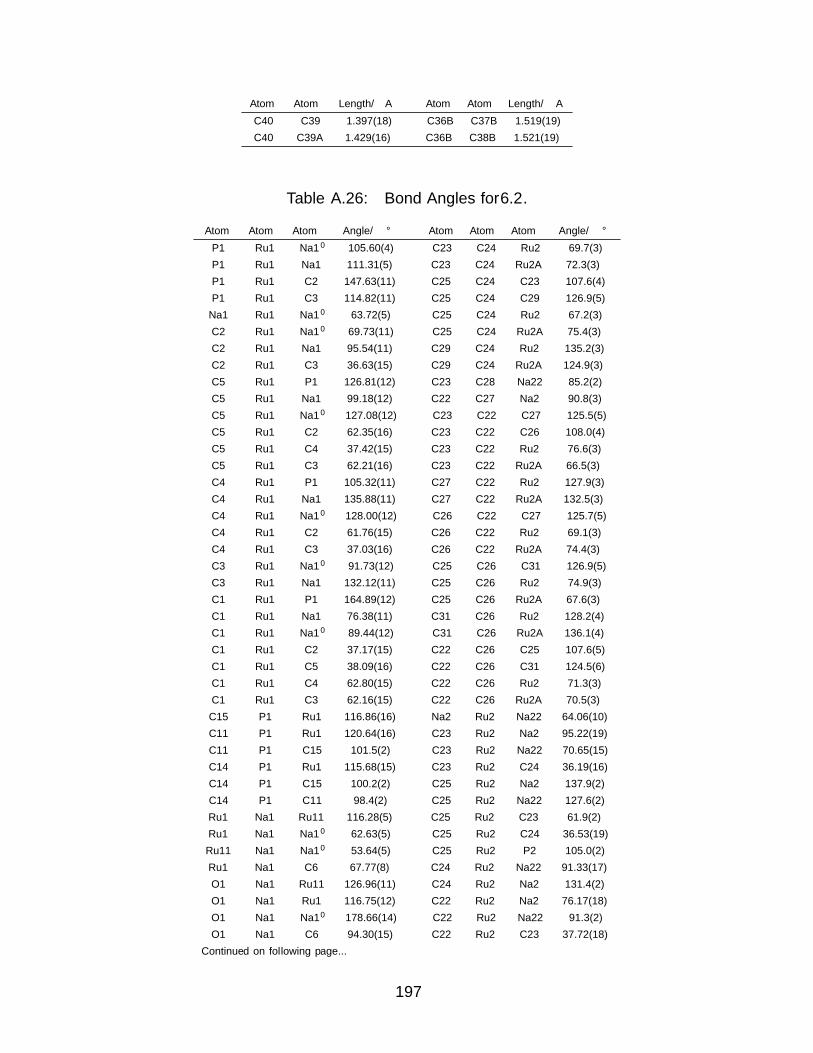
Atom Atom Length/A Atom Atom Length/A
C40 C39 1.397(18) C36B C37B 1.519(19)
C40 C39A 1.429(16) C36B C38B 1.521(19)
Table A.26: Bond Angles for 6.2.
Atom Atom Atom Angle/° Atom Atom Atom Angle/°
P1 Ru1 Na1′ 105.60(4) C23 C24 Ru2 69.7(3)
P1 Ru1 Na1 111.31(5) C23 C24 Ru2A 72.3(3)
P1 Ru1 C2 147.63(11) C25 C24 C23 107.6(4)
P1 Ru1 C3 114.82(11) C25 C24 C29 126.9(5)
Na1 Ru1 Na1′ 63.72(5) C25 C24 Ru2 67.2(3)
C2 Ru1 Na1′ 69.73(11) C25 C24 Ru2A 75.4(3)
C2 Ru1 Na1 95.54(11) C29 C24 Ru2 135.2(3)
C2 Ru1 C3 36.63(15) C29 C24 Ru2A 124.9(3)
C5 Ru1 P1 126.81(12) C23 C28 Na22 85.2(2)
C5 Ru1 Na1 99.18(12) C22 C27 Na2 90.8(3)
C5 Ru1 Na1′ 127.08(12) C23 C22 C27 125.5(5)
C5 Ru1 C2 62.35(16) C23 C22 C26 108.0(4)
C5 Ru1 C4 37.42(15) C23 C22 Ru2 76.6(3)
C5 Ru1 C3 62.21(16) C23 C22 Ru2A 66.5(3)
C4 Ru1 P1 105.32(11) C27 C22 Ru2 127.9(3)
C4 Ru1 Na1 135.88(11) C27 C22 Ru2A 132.5(3)
C4 Ru1 Na1′ 128.00(12) C26 C22 C27 125.7(5)
C4 Ru1 C2 61.76(15) C26 C22 Ru2 69.1(3)
C4 Ru1 C3 37.03(16) C26 C22 Ru2A 74.4(3)
C3 Ru1 Na1′ 91.73(12) C25 C26 C31 126.9(5)
C3 Ru1 Na1 132.12(11) C25 C26 Ru2 74.9(3)
C1 Ru1 P1 164.89(12) C25 C26 Ru2A 67.6(3)
C1 Ru1 Na1 76.38(11) C31 C26 Ru2 128.2(4)
C1 Ru1 Na1′ 89.44(12) C31 C26 Ru2A 136.1(4)
C1 Ru1 C2 37.17(15) C22 C26 C25 107.6(5)
C1 Ru1 C5 38.09(16) C22 C26 C31 124.5(6)
C1 Ru1 C4 62.80(15) C22 C26 Ru2 71.3(3)
C1 Ru1 C3 62.16(15) C22 C26 Ru2A 70.5(3)
C15 P1 Ru1 116.86(16) Na2 Ru2 Na22 64.06(10)
C11 P1 Ru1 120.64(16) C23 Ru2 Na2 95.22(19)
C11 P1 C15 101.5(2) C23 Ru2 Na22 70.65(15)
C14 P1 Ru1 115.68(15) C23 Ru2 C24 36.19(16)
C14 P1 C15 100.2(2) C25 Ru2 Na2 137.9(2)
C14 P1 C11 98.4(2) C25 Ru2 Na22 127.6(2)
Ru1 Na1 Ru11 116.28(5) C25 Ru2 C23 61.9(2)
Ru1 Na1 Na1′ 62.63(5) C25 Ru2 C24 36.53(19)
Ru11 Na1 Na1′ 53.64(5) C25 Ru2 P2 105.0(2)
Ru1 Na1 C6 67.77(8) C24 Ru2 Na22 91.33(17)
O1 Na1 Ru11 126.96(11) C24 Ru2 Na2 131.4(2)
O1 Na1 Ru1 116.75(12) C22 Ru2 Na2 76.17(18)
O1 Na1 Na1′ 178.66(14) C22 Ru2 Na22 91.3(2)
O1 Na1 C6 94.30(15) C22 Ru2 C23 37.72(18)
Continued on following page...
197

Atom Atom Atom Angle/° Atom Atom Atom Angle/°
O1 Na1 C71 89.53(15) C22 Ru2 C25 64.3(2)
C6 Na1 Ru11 106.41(11) C22 Ru2 C24 62.4(2)
C6 Na1 Na1′ 86.56(12) C22 Ru2 P2 155.3(2)
C71 Na1 Ru11 66.55(10) C26 Ru2 Na2 100.5(2)
C71 Na1 Ru1 115.69(11) C26 Ru2 Na22 130.2(2)
C71 Na1 Na1′ 89.73(12) C26 Ru2 C23 63.8(2)
C71 Na1 C6 172.88(15) C26 Ru2 C25 38.7(2)
C18 O1 Na1 120.1(4) C26 Ru2 C24 62.9(2)
C20 O1 Na1 128.6(4) C26 Ru2 C22 39.6(2)
C20 O1 C18 110.7(5) C26 Ru2 P2 118.0(3)
C3 C2 Ru1 72.6(2) P2 Ru2 Na22 111.76(18)
C3 C2 C7 124.5(4) P2 Ru2 Na2 105.14(18)
C1 C2 Ru1 69.8(2) P2 Ru2 C23 158.4(2)
C1 C2 C3 109.0(4) P2 Ru2 C24 123.2(2)
C1 C2 C7 125.6(4) C35 P2 Ru2 119.2(4)
C7 C2 Ru1 131.9(3) C35 P2 C32 103.4(6)
C17 C15 P1 116.0(4) C35 P2 C36 93.3(7)
C16 C15 P1 109.9(4) C32 P2 Ru2 119.9(5)
C16 C15 C17 110.6(5) C36 P2 Ru2 116.9(5)
C1 C6 Na1 84.2(2) C36 P2 C32 99.4(7)
C4 C5 Ru1 72.1(2) O2 C41 C42 115.8(18)
C4 C5 C1 107.5(4) C33 C32 P2 111.3(11)
C4 C5 C10 126.7(4) C33 C32 C34 107.5(15)
C1 C5 Ru1 70.7(2) C34 C32 P2 115.6(11)
C1 C5 C10 125.5(4) C40 C39 O2 106.6(13)
C10 C5 Ru1 127.3(3) C38 C36 P2 108.4(10)
C5 C4 Ru1 70.5(2) C37 C36 P2 111.3(10)
C5 C4 C3 108.4(4) C37 C36 C38 109.1(15)
C5 C4 C9 125.3(4) Na22 Ru2A Na2 63.85(9)
C3 C4 Ru1 72.9(2) C23 Ru2A Na22 76.60(16)
C3 C4 C9 125.8(4) C23 Ru2A Na2 90.41(16)
C9 C4 Ru1 129.0(3) C23 Ru2A C25 61.97(19)
C2 C3 Ru1 70.7(2) C23 Ru2A C22 36.46(17)
C2 C3 C4 107.5(4) C23 Ru2A C26 60.24(19)
C2 C3 C8 124.3(4) C23 Ru2A P2A 162.0(2)
C4 C3 Ru1 70.1(2) C25 Ru2A Na2 123.8(2)
C4 C3 C8 127.2(4) C25 Ru2A Na22 137.0(2)
C8 C3 Ru1 133.5(3) C25 Ru2A C22 60.0(2)
C2 C1 Ru1 73.0(2) C25 Ru2A C26 35.6(2)
C2 C1 C6 125.9(4) C24 Ru2A Na22 101.5(2)
C2 C1 C5 107.6(4) C24 Ru2A Na2 127.55(18)
C6 C1 Ru1 131.5(3) C24 Ru2A C23 38.18(17)
C5 C1 Ru1 71.2(2) C24 Ru2A C25 37.39(19)
C5 C1 C6 125.1(4) C24 Ru2A C22 61.65(19)
C2 C7 Na1′ 91.8(3) C24 Ru2A C26 60.9(2)
C13 C11 P1 110.6(3) C24 Ru2A P2A 124.4(2)
C13 C11 C12 110.4(5) C22 Ru2A Na22 93.43(17)
C12 C11 P1 111.4(3) C22 Ru2A Na2 69.02(15)
C19A C18 O1 94.5(10) C22 Ru2A C26 35.12(18)
C19 C18 O1 121.2(7) C26 Ru2A Na2 88.46(19)
Continued on following page...
198

Atom Atom Atom Angle/° Atom Atom Atom Angle/°
O1 C20 C21A 103.8(10) C26 Ru2A Na22 128.55(19)
C21 C20 O1 116.4(6) P2A Ru2A Na2 107.56(15)
C18 C19A C21A 110.2(15) P2A Ru2A C25 107.0(2)
C20 C21A C19A 81.6(19) P2A Ru2A C22 152.6(2)
O2 Na2 Na22 172.4(3) P2A Ru2A C26 120.1(2)
O2 Na2 C282 91.4(4) C35 P2A Ru2A 120.6(4)
O2 Na2 C27 92.5(4) C35 P2A C35B 33.2(7)
O2 Na2 Ru2 126.9(3) C35 P2A C32A 114.4(10)
O2 Na2 Ru22 117.0(3) C35 P2A C36A 68.3(7)
O2 Na2 Ru2A2 109.9(3) C35 P2A C36B 106.1(10)
C282 Na2 Na22 90.12(12) C35B P2A Ru2A 114.2(7)
C282 Na2 Ru2 112.20(15) C32A P2A Ru2A 119.6(9)
C282 Na2 Ru22 68.47(12) C32A P2A C35B 98.2(11)
C282 Na2 Ru2A 109.17(13) C32A P2A C36B 64.8(12)
C27 Na2 Na22 86.11(13) C36A P2A Ru2A 121.0(7)
C27 Na2 C282 176.04(17) C36A P2A C35B 99.4(9)
C27 Na2 Ru2 64.73(14) C36A P2A C32A 100.3(10)
C27 Na2 Ru22 110.23(16) C36A P2A C36B 43.8(11)
C27 Na2 Ru2A2 110.92(16) C32B P2A C35 95.5(10)
C27 Na2 Ru2A 67.49(12) C32B P2A Ru2A 113.1(9)
Ru22 Na2 Na22 56.90(9) C32B P2A C35B 67.9(11)
Ru2 Na2 Na22 59.04(9) C32B P2A C32A 36.9(11)
Ru2 Na2 Ru22 115.94(10) C32B P2A C36A 124.3(11)
Ru2A2 Na2 Ru2A 116.15(9) C32B P2A C36B 100.0(13)
O2A Na2 C27 96.3(4) C36B P2A Ru2A 117.5(9)
O2A Na2 Ru2A2 122.4(4) C36B P2A C35B 127.2(11)
O2A Na2 Ru2A 121.1(3) C40 C39A O2A 103.3(12)
C41 O2 Na2 126.9(12) P2A C32A C36B 57.7(10)
C41 O2 C39 98.2(14) C34A C32A P2A 121.3(18)
C39 O2 Na2 117.0(9) C34A C32A C33A 106(2)
C39A C40 C42A 105.5(10) C34A C32A C36B 94.3(18)
C24 C23 C28 125.1(4) C33A C32A P2A 106(2)
C24 C23 Ru2 74.1(3) C33A C32A C36B 159(2)
C24 C23 Ru2A 69.5(2) C37A C36A P2A 105.6(17)
C28 C23 Ru2 135.6(3) C37A C36A C38A 116(2)
C28 C23 Ru2A 129.0(3) C38A C36A P2A 109.2(14)
C22 C23 C24 108.2(4) C41A C42A C40 102.3(10)
C22 C23 C28 125.4(4) O2A C41A C42A 104.1(12)
C22 C23 Ru2 65.7(3) C39A O2A Na2 128.9(9)
C22 C23 Ru2A 77.1(3) C41A O2A Na2 119.9(9)
C24 C25 C30 124.7(6) C41A O2A C39A 111.2(12)
C24 C25 C26 108.5(4) C34B C32B P2A 107.6(17)
C24 C25 Ru2 76.2(3) C34B C32B C33B 105(2)
C24 C25 Ru2A 67.2(3) C33B C32B P2A 121(2)
C30 C25 Ru2 129.4(4) P2A C36B C32A 57.5(11)
C30 C25 Ru2A 127.8(4) C37B C36B P2A 119(2)
C26 C25 C30 126.4(6) C37B C36B C32A 175(2)
C26 C25 Ru2 66.4(3) C37B C36B C38B 97(3)
C26 C25 Ru2A 76.8(3) C38B C36B P2A 123(2)
C23 C24 C29 124.9(5) C38B C36B C32A 89(2)
199

Compound 6.7
Table A.27: Bond Lengths for 6.7.
Atom Atom Length/A Atom Atom Length/A
Ir1 Ru1 2.5659(5) C2 C12 1.501(8)
Ir1 C10 2.101(6) C3 C1 1.447(7)
Ir1 C18 2.156(5) C3 C8 1.489(8)
Ir1 C16 2.133(6) C1 C9 1.420(8)
Ir1 C1B 2.124(6) C1 C20 1.503(7)
Ru1 P1 2.3074(14) C5 C11 1.525(8)
Ru1 C4 2.191(5) C5 C13 1.530(8)
Ru1 C2 2.221(5) C6 C15 1.526(9)
Ru1 C3 2.181(5) C6 C19 1.540(8)
Ru1 C1 2.182(5) C7 C9 1.502(8)
Ru1 C9 2.182(6) C10 C16 1.407(8)
P1 C5 1.854(6) C10 C1D 1.505(8)
P1 C6 1.862(6) C17 C1B 1.510(8)
P1 C1E 1.831(6) C17 C1C 1.507(9)
C4 C2 1.448(8) C18 C1A 1.522(8)
C4 C9 1.450(7) C18 C1B 1.426(8)
C4 C14 1.489(8) C16 C1C 1.524(8)
C2 C3 1.415(7) C1A C1D 1.499(10)
Table A.28: Bond Angles for 6.7.
Atom Atom Atom Angle/° Atom Atom Atom Angle/°
C10 Ir1 Ru1 126.03(17) C3 C2 Ru1 69.7(3)
C10 Ir1 C18 80.7(2) C3 C2 C4 109.2(5)
C10 Ir1 C16 38.8(2) C3 C2 C12 125.9(5)
C10 Ir1 C1B 96.3(2) C12 C2 Ru1 132.7(4)
C18 Ir1 Ru1 134.23(16) C2 C3 Ru1 72.8(3)
C16 Ir1 Ru1 134.71(17) C2 C3 C1 107.9(5)
C16 Ir1 C18 90.2(2) C2 C3 C8 126.4(5)
C1B Ir1 Ru1 137.43(17) C1 C3 Ru1 70.7(3)
C1B Ir1 C18 38.9(2) C1 C3 C8 125.2(5)
C1B Ir1 C16 80.4(2) C8 C3 Ru1 128.0(4)
P1 Ru1 Ir1 93.01(4) C3 C1 Ru1 70.6(3)
C4 Ru1 Ir1 141.78(14) C3 C1 C20 126.8(5)
C4 Ru1 P1 109.23(14) C9 C1 Ru1 71.0(3)
C4 Ru1 C2 38.3(2) C9 C1 C3 107.8(5)
C2 Ru1 Ir1 162.81(13) C9 C1 C20 125.2(5)
C2 Ru1 P1 102.41(14) C20 C1 Ru1 127.9(4)
C3 Ru1 Ir1 126.04(13) C11 C5 P1 112.6(4)
C3 Ru1 P1 125.67(14) C11 C5 C13 110.2(5)
C3 Ru1 C4 64.5(2) C13 C5 P1 111.2(4)
C3 Ru1 C2 37.48(19) C15 C6 P1 110.2(4)
C3 Ru1 C1 38.72(19) C15 C6 C19 110.2(5)
Continued on following page...
200

Atom Atom Atom Angle/° Atom Atom Atom Angle/°
C3 Ru1 C9 64.1(2) C19 C6 P1 115.6(4)
C1 Ru1 Ir1 100.31(14) C4 C9 Ru1 71.0(3)
C1 Ru1 P1 164.20(15) C4 C9 C7 124.8(5)
C1 Ru1 C4 64.57(19) C1 C9 Ru1 71.0(3)
C1 Ru1 C2 63.37(19) C1 C9 C4 109.0(5)
C9 Ru1 Ir1 107.66(15) C1 C9 C7 126.2(5)
C9 Ru1 P1 143.95(15) C7 C9 Ru1 124.7(4)
C9 Ru1 C4 38.72(19) C16 C10 Ir1 71.8(3)
C9 Ru1 C2 63.4(2) C16 C10 C1D 126.2(6)
C9 Ru1 C1 38.0(2) C1D C10 Ir1 112.1(4)
C5 P1 Ru1 117.1(2) C1C C17 C1B 113.2(5)
C5 P1 C6 103.0(3) C1A C18 Ir1 113.1(4)
C6 P1 Ru1 114.96(18) C1B C18 Ir1 69.3(3)
C1E P1 Ru1 117.5(2) C1B C18 C1A 123.0(5)
C1E P1 C5 100.4(3) C10 C16 Ir1 69.4(3)
C1E P1 C6 101.3(3) C10 C16 C1C 122.6(6)
C2 C4 Ru1 72.0(3) C1C C16 Ir1 114.5(4)
C2 C4 C9 106.1(4) C1D C1A C18 112.3(5)
C2 C4 C14 126.7(5) C17 C1B Ir1 112.7(4)
C9 C4 Ru1 70.3(3) C18 C1B Ir1 71.8(3)
C9 C4 C14 126.4(5) C18 C1B C17 124.7(6)
C14 C4 Ru1 130.4(4) C17 C1C C16 112.3(5)
C4 C2 Ru1 69.7(3) C1A C1D C10 113.6(5)
C4 C2 C12 124.5(5)
Compound 6.8
Table A.29: Bond Lengths for 6.8.
Atom Atom Length/A Atom Atom Length/A
Ru1 Cu1 2.4833(4) C14 C45 1.502(4)
Ru1 P1 2.2492(8) C15 C25 1.531(4)
Ru1 C8 2.211(3) C15 C33 1.527(4)
Ru1 C14 2.207(3) C16 C36 1.443(5)
Ru1 C16 2.231(3) C16 C52 1.505(5)
Ru1 C36 2.237(3) C17 C22 1.519(4)
Ru1 C37 2.206(3) C17 C27 1.523(4)
Cu1 C2 1.906(3) C17 C40 1.536(4)
P1 C26 1.842(3) C18 C29 1.377(4)
P1 C1 1.862(3) C19 C20 1.515(4)
P1 C4 1.857(3) C19 C24 1.403(4)
C2 N4 1.357(4) C20 C43 1.524(5)
C2 N5 1.360(4) C20 C49 1.511(4)
C3 N4 1.387(3) C22 C31 1.398(4)
C3 C21 1.344(4) C24 C44 1.380(5)
N4 C6 1.454(4) C28 C30 1.524(4)
N5 C12 1.448(4) C29 C31 1.380(4)
N5 C21 1.386(4) C30 C32 1.523(4)
C6 C19 1.392(4) C30 C46 1.530(4)
Continued on following page...
201

Atom Atom Length/A Atom Atom Length/A
C6 C32 1.404(4) C32 C39 1.399(4)
C8 C14 1.430(4) C35 C37 1.503(5)
C8 C16 1.421(4) C36 C37 1.414(5)
C8 C41 1.505(5) C36 C38 1.506(4)
C10 C12 1.395(4) C39 C44 1.378(5)
C10 C15 1.520(4) C42 C4 1.537(5)
C10 C18 1.401(4) C47 C1 1.516(4)
C12 C22 1.398(4) C48 C4 1.528(5)
C14 C37 1.436(5) C50 C1 1.524(5)
Table 5 Bond Angles for 6.8.
Atom Atom Atom Angle/° Atom Atom Atom Angle/°
P1 Ru1 Cu1 97.74(2) C37 C14 Ru1 70.98(17)
C8 Ru1 Cu1 111.70(8) C37 C14 C45 126.0(3)
C8 Ru1 P1 136.99(9) C45 C14 Ru1 128.1(2)
C8 Ru1 C16 37.32(11) C10 C15 C25 110.5(2)
C8 Ru1 C36 62.54(11) C10 C15 C33 113.4(3)
C14 Ru1 Cu1 95.20(8) C33 C15 C25 112.0(3)
C14 Ru1 P1 166.69(8) C8 C16 Ru1 70.55(17)
C14 Ru1 C8 37.77(12) C8 C16 C36 107.4(3)
C14 Ru1 C16 62.96(11) C8 C16 C52 124.7(3)
C14 Ru1 C36 62.73(11) C36 C16 Ru1 71.39(17)
C16 Ru1 Cu1 148.53(9) C36 C16 C52 127.3(3)
C16 Ru1 P1 106.23(9) C52 C16 Ru1 129.8(2)
C16 Ru1 C36 37.68(12) C22 C17 C27 113.4(3)
C36 Ru1 Cu1 151.60(9) C22 C17 C40 110.0(2)
C36 Ru1 P1 104.01(8) C27 C17 C40 111.2(3)
C37 Ru1 Cu1 114.56(9) C29 C18 C10 121.1(3)
C37 Ru1 P1 131.46(9) C6 C19 C20 122.9(3)
C37 Ru1 C8 62.97(12) C6 C19 C24 116.9(3)
C37 Ru1 C14 37.98(12) C24 C19 C20 120.1(3)
C37 Ru1 C16 62.80(12) C19 C20 C43 109.5(3)
C37 Ru1 C36 37.09(12) C49 C20 C19 113.8(3)
C2 Cu1 Ru1 174.30(9) C49 C20 C43 110.7(3)
C26 P1 Ru1 117.47(12) C3 C21 N5 106.4(2)
C26 P1 C1 97.52(15) C12 C22 C17 121.9(3)
C26 P1 C4 99.79(16) C12 C22 C31 116.8(3)
C1 P1 Ru1 119.41(10) C31 C22 C17 121.3(3)
C4 P1 Ru1 116.46(11) C44 C24 C19 120.9(3)
C4 P1 C1 102.72(15) C18 C29 C31 120.4(3)
N4 C2 Cu1 127.6(2) C28 C30 C46 109.7(3)
N4 C2 N5 103.0(2) C32 C30 C28 111.4(3)
N5 C2 Cu1 129.4(2) C32 C30 C46 113.4(3)
C21 C3 N4 106.3(2) C29 C31 C22 121.3(3)
C2 N4 C3 112.1(2) C6 C32 C30 122.2(3)
C2 N4 C6 124.2(2) C39 C32 C6 116.9(3)
C3 N4 C6 123.6(2) C39 C32 C30 120.9(3)
C2 N5 C12 124.5(2) C16 C36 Ru1 70.93(17)
Continued on following page...
202

Atom Atom Atom Angle/° Atom Atom Atom Angle/°
C2 N5 C21 112.0(2) C16 C36 C38 125.8(3)
C21 N5 C12 123.4(2) C37 C36 Ru1 70.25(17)
C19 C6 N4 118.5(3) C37 C36 C16 108.0(3)
C19 C6 C32 123.6(3) C37 C36 C38 125.5(3)
C32 C6 N4 117.9(3) C38 C36 Ru1 131.5(2)
C14 C8 Ru1 70.97(17) C14 C37 Ru1 71.04(17)
C14 C8 C41 126.6(3) C14 C37 C35 124.5(3)
C16 C8 Ru1 72.13(18) C35 C37 Ru1 126.2(2)
C16 C8 C14 108.8(3) C36 C37 Ru1 72.66(18)
C16 C8 C41 124.5(3) C36 C37 C14 108.5(3)
C41 C8 Ru1 126.3(2) C36 C37 C35 126.7(3)
C12 C10 C15 122.2(3) C44 C39 C32 120.9(3)
C12 C10 C18 117.0(3) C39 C44 C24 120.9(3)
C18 C10 C15 120.8(3) C47 C1 P1 113.1(2)
C10 C12 N5 118.5(3) C47 C1 C50 110.4(3)
C10 C12 C22 123.4(3) C50 C1 P1 109.8(2)
C22 C12 N5 118.0(3) C42 C4 P1 116.8(2)
C8 C14 Ru1 71.26(17) C48 C4 P1 109.5(2)
C8 C14 C37 107.2(3) C48 C4 C42 110.6(3)
C8 C14 C45 126.5(3)
A.5 Crystallographic Data Tables for Chapter 7
Compound 7.1
Table A.31: Bond Lengths for .
Atom Atom Length/A Atom Atom Length/A
Sn1 Ru1 2.6399(4) C3 C2 1.420(6)
Sn1 C18 2.270(4) C3 C8 1.504(5)
Ru1 P1 2.2676(11) C15 C16 1.527(6)
Ru1 C4 2.245(4) C15 C17 1.536(6)
Ru1 C1 2.272(4) C29 C24 1.405(6)
Ru1 C5 2.237(4) C29 C28 1.397(6)
Ru1 C3 2.289(4) C29 C32 1.504(6)
Ru1 C2 2.280(4) C31 C27 1.507(5)
P1 C15 1.860(4) C2 C7 1.503(5)
P1 C14 1.816(4) C41 C38 1.520(5)
P1 C11 1.873(4) C25 C26 1.401(6)
C4 C5 1.439(6) C25 C24 1.415(5)
C4 C3 1.433(6) C25 C30 1.503(6)
C4 C9 1.501(6) C33 C38 1.407(5)
C20 C19 1.385(6) C26 C27 1.384(6)
C20 C21 1.382(6) C37 C38 1.391(6)
C1 C5 1.418(6) C37 C36 1.389(6)
C1 C6 1.497(5) C24 C19 1.499(5)
C1 C2 1.427(5) C19 C18 1.417(5)
C5 C10 1.505(6) C36 C40 1.512(6)
C34 C39 1.505(5) C36 C35 1.381(6)
Continued on following page...
203
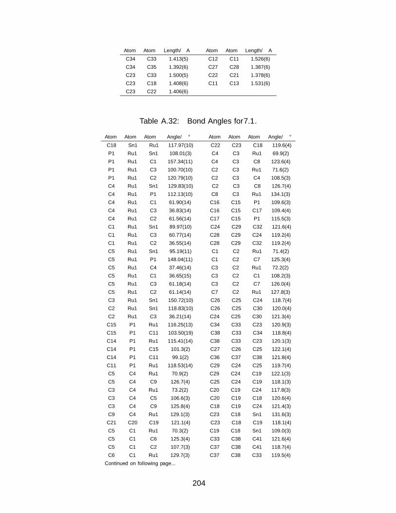
Atom Atom Length/A Atom Atom Length/A
C34 C33 1.413(5) C12 C11 1.526(6)
C34 C35 1.392(6) C27 C28 1.387(6)
C23 C33 1.500(5) C22 C21 1.378(6)
C23 C18 1.408(6) C11 C13 1.531(6)
C23 C22 1.406(6)
Table A.32: Bond Angles for 7.1.
Atom Atom Atom Angle/° Atom Atom Atom Angle/°
C18 Sn1 Ru1 117.97(10) C22 C23 C18 119.6(4)
P1 Ru1 Sn1 108.01(3) C4 C3 Ru1 69.9(2)
P1 Ru1 C1 157.34(11) C4 C3 C8 123.6(4)
P1 Ru1 C3 100.70(10) C2 C3 Ru1 71.6(2)
P1 Ru1 C2 120.79(10) C2 C3 C4 108.5(3)
C4 Ru1 Sn1 129.83(10) C2 C3 C8 126.7(4)
C4 Ru1 P1 112.13(10) C8 C3 Ru1 134.1(3)
C4 Ru1 C1 61.90(14) C16 C15 P1 109.6(3)
C4 Ru1 C3 36.83(14) C16 C15 C17 109.4(4)
C4 Ru1 C2 61.56(14) C17 C15 P1 115.5(3)
C1 Ru1 Sn1 89.97(10) C24 C29 C32 121.6(4)
C1 Ru1 C3 60.77(14) C28 C29 C24 119.2(4)
C1 Ru1 C2 36.55(14) C28 C29 C32 119.2(4)
C5 Ru1 Sn1 95.19(11) C1 C2 Ru1 71.4(2)
C5 Ru1 P1 148.04(11) C1 C2 C7 125.3(4)
C5 Ru1 C4 37.46(14) C3 C2 Ru1 72.2(2)
C5 Ru1 C1 36.65(15) C3 C2 C1 108.2(3)
C5 Ru1 C3 61.18(14) C3 C2 C7 126.0(4)
C5 Ru1 C2 61.14(14) C7 C2 Ru1 127.8(3)
C3 Ru1 Sn1 150.72(10) C26 C25 C24 118.7(4)
C2 Ru1 Sn1 118.83(10) C26 C25 C30 120.0(4)
C2 Ru1 C3 36.21(14) C24 C25 C30 121.3(4)
C15 P1 Ru1 116.25(13) C34 C33 C23 120.9(3)
C15 P1 C11 103.50(19) C38 C33 C34 118.8(4)
C14 P1 Ru1 115.41(14) C38 C33 C23 120.1(3)
C14 P1 C15 101.3(2) C27 C26 C25 122.1(4)
C14 P1 C11 99.1(2) C36 C37 C38 121.8(4)
C11 P1 Ru1 118.53(14) C29 C24 C25 119.7(4)
C5 C4 Ru1 70.9(2) C29 C24 C19 122.1(3)
C5 C4 C9 126.7(4) C25 C24 C19 118.1(3)
C3 C4 Ru1 73.2(2) C20 C19 C24 117.8(3)
C3 C4 C5 106.6(3) C20 C19 C18 120.6(4)
C3 C4 C9 125.8(4) C18 C19 C24 121.4(3)
C9 C4 Ru1 129.1(3) C23 C18 Sn1 131.6(3)
C21 C20 C19 121.1(4) C23 C18 C19 118.1(4)
C5 C1 Ru1 70.3(2) C19 C18 Sn1 109.0(3)
C5 C1 C6 125.3(4) C33 C38 C41 121.6(4)
C5 C1 C2 107.7(3) C37 C38 C41 118.7(4)
C6 C1 Ru1 129.7(3) C37 C38 C33 119.5(4)
Continued on following page...
204

Atom Atom Atom Angle/° Atom Atom Atom Angle/°
C2 C1 Ru1 72.1(2) C37 C36 C40 121.1(4)
C2 C1 C6 126.5(4) C35 C36 C37 118.0(4)
C4 C5 Ru1 71.6(2) C35 C36 C40 120.9(4)
C4 C5 C10 124.9(4) C26 C27 C31 121.1(4)
C1 C5 Ru1 73.0(2) C26 C27 C28 118.3(4)
C1 C5 C4 108.8(3) C28 C27 C31 120.6(4)
C1 C5 C10 125.8(4) C21 C22 C23 121.4(4)
C10 C5 Ru1 127.3(3) C27 C28 C29 122.0(4)
C33 C34 C39 122.7(4) C12 C11 P1 113.3(3)
C35 C34 C39 118.3(4) C12 C11 C13 109.6(4)
C35 C34 C33 119.0(4) C13 C11 P1 111.2(3)
C18 C23 C33 122.3(3) C22 C21 C20 119.2(4)
C22 C23 C33 118.1(3) C36 C35 C34 122.3(4)
Compound 7.2
Table A.33: Bond Lengths for 7.2.
Atom Atom Length/A Atom Atom Length/A
Pb1 Ru1 2.6984(4) C18 C23 1.420(5)
Pb1 C18 2.356(4) C44 C43 1.389(6)
Ru1 P1 2.2746(11) C44 C51 1.531(5)
Ru1 C3 2.293(4) C21 C22 1.380(6)
Ru1 C4 2.267(4) C26 C27 1.393(6)
Ru1 C5 2.232(4) C4 C5 1.437(6)
Ru1 C1 2.242(4) C4 C9 1.495(6)
Ru1 C2 2.264(4) C22 C23 1.397(5)
P1 C14 1.850(4) C38 C36 1.532(6)
P1 C15 1.878(4) C15 C17 1.520(6)
P1 C11 1.863(4) C15 C16 1.517(6)
C39 C44 1.413(6) C43 C42 1.377(6)
C39 C40 1.408(5) C28 C29 1.388(5)
C39 C23 1.510(6) C28 C27 1.380(6)
C3 C4 1.419(6) C5 C1 1.418(6)
C3 C2 1.424(6) C5 C10 1.497(6)
C3 C8 1.501(6) C24 C29 1.403(5)
C45 C40 1.534(6) C51 C52 1.518(6)
C45 C47 1.528(6) C51 C53 1.524(6)
C45 C46 1.527(6) C1 C2 1.427(6)
C41 C40 1.398(6) C1 C6 1.499(6)
C41 C42 1.389(6) C30 C31 1.531(6)
C33 C27 1.525(5) C30 C32 1.523(6)
C33 C34 1.523(7) C2 C7 1.501(6)
C33 C35 1.506(7) C29 C36 1.524(5)
C20 C19 1.387(6) C42 C48 1.536(6)
C20 C21 1.386(6) C12 C11 1.519(6)
C19 C18 1.403(6) C50 C48 1.524(7)
C19 C24 1.518(5) C36 C37 1.530(6)
C25 C26 1.391(5) C11 C13 1.525(6)
Continued on following page...
205

Atom Atom Length/A Atom Atom Length/A
C25 C24 1.415(5) C48 C49 1.500(6)
C25 C30 1.521(6)
Table A.34: Bond Angles for 7.2.
Atom Atom Atom Angle/° Atom Atom Atom Angle/°
C18 Pb1 Ru1 119.28(9) C25 C26 C27 122.2(4)
P1 Ru1 Pb1 107.75(3) C3 C4 Ru1 72.9(2)
P1 Ru1 C3 103.88(11) C3 C4 C5 107.6(4)
C3 Ru1 Pb1 148.37(11) C3 C4 C9 127.3(4)
C4 Ru1 Pb1 120.81(11) C5 C4 Ru1 70.1(2)
C4 Ru1 P1 120.90(11) C5 C4 C9 124.4(4)
C4 Ru1 C3 36.27(15) C9 C4 Ru1 130.1(3)
C5 Ru1 Pb1 88.40(11) C21 C22 C23 121.1(4)
C5 Ru1 P1 157.63(12) C18 C23 C39 122.4(4)
C5 Ru1 C3 61.22(15) C22 C23 C39 117.5(3)
C5 Ru1 C4 37.24(15) C22 C23 C18 119.9(4)
C5 Ru1 C1 36.94(16) C17 C15 P1 115.6(3)
C5 Ru1 C2 61.73(16) C16 C15 P1 110.4(3)
C1 Ru1 Pb1 89.84(11) C16 C15 C17 109.4(4)
C1 Ru1 P1 152.75(12) C42 C43 C44 122.5(4)
C1 Ru1 C3 60.94(16) C27 C28 C29 122.6(4)
C1 Ru1 C4 61.56(15) C4 C5 Ru1 72.7(2)
C1 Ru1 C2 36.91(16) C4 C5 C10 125.9(4)
C2 Ru1 Pb1 122.88(12) C1 C5 Ru1 71.9(2)
C2 Ru1 P1 117.34(12) C1 C5 C4 107.9(4)
C2 Ru1 C3 36.41(16) C1 C5 C10 125.9(4)
C2 Ru1 C4 61.27(16) C10 C5 Ru1 125.7(3)
C14 P1 Ru1 114.49(14) C25 C24 C19 119.4(3)
C14 P1 C15 101.5(2) C29 C24 C19 121.3(3)
C14 P1 C11 102.0(2) C29 C24 C25 118.9(3)
C15 P1 Ru1 117.40(14) C52 C51 C44 114.1(4)
C11 P1 Ru1 117.77(15) C52 C51 C53 110.9(4)
C11 P1 C15 101.1(2) C53 C51 C44 109.3(3)
C44 C39 C23 119.6(3) C5 C1 Ru1 71.1(2)
C40 C39 C44 119.0(4) C5 C1 C2 108.4(4)
C40 C39 C23 121.1(3) C5 C1 C6 126.4(4)
C4 C3 Ru1 70.8(2) C2 C1 Ru1 72.4(2)
C4 C3 C2 108.5(4) C2 C1 C6 124.9(4)
C4 C3 C8 127.8(4) C6 C1 Ru1 127.1(3)
C2 C3 Ru1 70.7(2) C25 C30 C31 112.5(4)
C2 C3 C8 123.3(4) C25 C30 C32 110.6(4)
C8 C3 Ru1 129.9(3) C32 C30 C31 110.8(4)
C47 C45 C40 110.9(3) C3 C2 Ru1 72.9(2)
C46 C45 C40 113.5(4) C3 C2 C1 107.6(4)
C46 C45 C47 108.2(3) C3 C2 C7 126.3(4)
C42 C41 C40 122.2(4) C1 C2 Ru1 70.7(2)
C34 C33 C27 111.0(4) C1 C2 C7 125.0(4)
Continued on following page...
206

Atom Atom Atom Angle/° Atom Atom Atom Angle/°
C35 C33 C27 113.7(4) C7 C2 Ru1 131.1(3)
C35 C33 C34 110.8(4) C28 C29 C24 119.5(4)
C21 C20 C19 120.6(4) C28 C29 C36 119.1(4)
C20 C19 C18 121.1(3) C24 C29 C36 121.3(3)
C20 C19 C24 116.3(4) C41 C42 C48 121.8(4)
C18 C19 C24 122.4(4) C43 C42 C41 117.9(4)
C26 C25 C24 119.2(4) C43 C42 C48 120.3(4)
C26 C25 C30 119.0(3) C26 C27 C33 122.2(4)
C24 C25 C30 121.7(3) C28 C27 C33 120.3(4)
C19 C18 Pb1 113.4(3) C28 C27 C26 117.5(4)
C19 C18 C23 117.8(4) C29 C36 C38 110.3(3)
C23 C18 Pb1 126.3(3) C29 C36 C37 112.0(3)
C39 C44 C51 121.7(4) C37 C36 C38 108.8(4)
C43 C44 C39 119.4(4) C12 C11 P1 111.2(3)
C43 C44 C51 118.6(4) C12 C11 C13 109.4(4)
C22 C21 C20 119.4(4) C13 C11 P1 113.0(3)
C39 C40 C45 122.6(4) C50 C48 C42 110.7(4)
C41 C40 C39 119.1(4) C49 C48 C42 113.5(4)
C41 C40 C45 118.3(4) C49 C48 C50 110.7(4)
Compound 7.3
Table A.35: Bond Lengths for 7.3.
Atom Atom Length/A Atom Atom Length/A
Sn1 Ru1 2.6057(10) C20 C21 1.401(6)
Sn1 C19 2.227(4) C34 C35 1.403(7)
Sn1 C1 2.180(8) C28 C29 1.398(7)
Sn1 I1 2.827(2) C28 C27 1.392(7)
C1A Sn1A 2.08(4) C28 C32 1.510(7)
Ru1 P1 2.2986(12) C6 C5 1.418(7)
Ru1 C2 2.271(4) C6 C11 1.500(7)
Ru1 C6 2.231(5) C26 C27 1.388(7)
Ru1 C5 2.238(5) C26 C31 1.499(7)
Ru1 C4 2.278(5) C21 C22 1.386(7)
Ru1 C3 2.285(5) C5 C4 1.425(8)
Ru1 Sn1A 2.549(8) C5 C10 1.509(8)
P1 C15 1.825(5) C4 C3 1.430(8)
P1 C16 1.860(5) C4 C9 1.485(7)
P1 C12 1.857(5) C38 C37 1.387(7)
C25 C30 1.394(6) C22 C23 1.381(7)
C25 C20 1.503(6) C3 C8 1.500(7)
C25 C26 1.402(6) C35 C36 1.393(7)
C30 C33 1.512(6) C35 C40 1.504(7)
C30 C29 1.386(7) C37 C36 1.388(7)
C19 C24 1.423(6) C37 C41 1.505(7)
C19 C20 1.417(6) C16 C17 1.536(7)
C19 Sn1A 2.274(12) C16 C18 1.536(7)
C2 C6 1.440(7) C12 C14 1.532(8)
Continued on following page...
207

Atom Atom Length/A Atom Atom Length/A
C2 C3 1.413(7) C12 C13 1.532(8)
C2 C7 1.495(6) C44 C45 1.385(13)
C39 C34 1.401(6) C44 C43 1.272(12)
C39 C38 1.388(7) C44 F2 1.17(2)
C39 C42 1.508(7) C45 C431 1.446(13)
C24 C34 1.508(6) C43 F1 1.30(2)
C24 C23 1.392(6) I1A Sn1A 2.94(3)
Table A.36: Bond Angles for 7.3.
Atom Atom Atom Angle/° Atom Atom Atom Angle/°
Ru1 Sn1 I1 117.34(10) C39 C34 C24 119.8(4)
C19 Sn1 Ru1 127.70(12) C39 C34 C35 119.8(4)
C19 Sn1 I1 97.62(13) C35 C34 C24 119.9(4)
C1 Sn1 Ru1 107.21(19) C29 C28 C32 121.4(5)
C1 Sn1 C19 111.5(3) C27 C28 C29 118.0(4)
C1 Sn1 I1 88.6(2) C27 C28 C32 120.6(5)
P1 Ru1 Sn1 106.09(8) C2 C6 Ru1 72.9(3)
P1 Ru1 Sn1A 95.8(7) C2 C6 C11 123.8(4)
C2 Ru1 Sn1 90.86(14) C5 C6 Ru1 71.7(3)
C2 Ru1 P1 159.21(12) C5 C6 C2 108.2(4)
C2 Ru1 C4 60.87(17) C5 C6 C11 126.9(5)
C2 Ru1 C3 36.15(17) C11 C6 Ru1 130.7(3)
C2 Ru1 Sn1A 102.0(7) C25 C26 C31 121.4(4)
C6 Ru1 Sn1 101.70(13) C27 C26 C25 119.8(4)
C6 Ru1 P1 143.60(13) C27 C26 C31 118.6(4)
C6 Ru1 C2 37.29(17) C22 C21 C20 121.0(4)
C6 Ru1 C5 37.01(17) C6 C5 Ru1 71.2(3)
C6 Ru1 C4 61.26(18) C6 C5 C4 107.8(4)
C6 Ru1 C3 61.29(18) C6 C5 C10 125.7(5)
C6 Ru1 Sn1A 108.7(5) C4 C5 Ru1 73.1(3)
C5 Ru1 Sn1 137.56(14) C4 C5 C10 125.6(5)
C5 Ru1 P1 109.19(12) C10 C5 Ru1 129.6(4)
C5 Ru1 C2 61.80(17) C5 C4 Ru1 70.1(3)
C5 Ru1 C4 36.8(2) C5 C4 C3 108.1(4)
C5 Ru1 C3 61.4(2) C5 C4 C9 125.0(5)
C5 Ru1 Sn1A 141.7(3) C3 C4 Ru1 72.0(3)
C4 Ru1 Sn1 150.68(16) C3 C4 C9 125.5(5)
C4 Ru1 P1 100.25(13) C9 C4 Ru1 134.0(4)
C4 Ru1 C3 36.52(19) C30 C29 C28 121.7(5)
C4 Ru1 Sn1A 162.3(8) C37 C38 C39 121.9(5)
C3 Ru1 Sn1 115.26(16) C23 C22 C21 119.0(4)
C3 Ru1 P1 123.30(13) C2 C3 Ru1 71.4(3)
C3 Ru1 Sn1A 126.6(8) C2 C3 C4 108.3(5)
C15 P1 Ru1 116.67(17) C2 C3 C8 124.4(5)
C15 P1 C16 101.2(2) C4 C3 Ru1 71.5(3)
C15 P1 C12 100.6(2) C4 C3 C8 126.9(5)
C16 P1 Ru1 114.11(16) C8 C3 Ru1 128.7(4)
Continued on following page...
208

Atom Atom Atom Angle/° Atom Atom Atom Angle/°
C12 P1 Ru1 118.37(17) C22 C23 C24 121.4(4)
C12 P1 C16 103.4(2) C34 C35 C40 120.8(4)
C30 C25 C20 120.1(4) C36 C35 C34 118.7(4)
C30 C25 C26 119.4(4) C36 C35 C40 120.5(4)
C26 C25 C20 119.5(4) C26 C27 C28 121.3(5)
C25 C30 C33 122.1(4) C38 C37 C36 117.8(4)
C29 C30 C25 119.6(4) C38 C37 C41 120.6(5)
C29 C30 C33 118.1(4) C36 C37 C41 121.5(5)
C24 C19 Sn1 120.7(3) C37 C36 C35 122.3(5)
C24 C19 Sn1A 133.5(9) C17 C16 P1 110.3(3)
C20 C19 Sn1 122.5(3) C18 C16 P1 116.2(4)
C20 C19 C24 116.7(4) C18 C16 C17 109.6(4)
C20 C19 Sn1A 109.4(9) C14 C12 P1 112.8(4)
C6 C2 Ru1 69.9(3) C14 C12 C13 110.2(5)
C6 C2 C7 124.1(4) C13 C12 P1 112.0(4)
C3 C2 Ru1 72.5(3) C43 C44 C45 121.2(10)
C3 C2 C6 107.6(4) F2 C44 C45 129.1(16)
C3 C2 C7 126.9(4) F2 C44 C43 108.5(17)
C7 C2 Ru1 133.7(3) C44 C45 C431 120.3(9)
C34 C39 C42 121.5(4) C44 C43 C451 118.5(10)
C38 C39 C34 119.4(5) C44 C43 F1 117.0(14)
C38 C39 C42 119.0(4) F1 C43 C451 123.1(12)
C19 C24 C34 124.9(4) C1A Sn1A Ru1 126.1(14)
C23 C24 C19 121.0(4) C1A Sn1A C19 100.7(11)
C23 C24 C34 114.1(4) C1A Sn1A I1A 89.6(13)
C19 C20 C25 125.3(4) Ru1 Sn1A I1A 95.7(6)
C21 C20 C25 113.8(4) C19 Sn1A Ru1 128.2(5)
C21 C20 C19 120.9(4) C19 Sn1A I1A 106.4(11)
Compound 7.4
Table A.37: Bond Lengths for 7.4.
Atom Atom Length/A Atom Atom Length/A
Sn1 Ru1 2.4731(3) C7 C8 1.494(5)
Sn1 Cl1 2.4554(8) C21 C20 1.380(5)
Sn1 C32 2.198(3) C21 C22 1.508(5)
Ru1 P1 2.2919(8) C24 C26 1.397(5)
Ru1 C3 2.256(3) C24 C25 1.509(5)
Ru1 C9 2.234(3) C27 C28 1.388(5)
Ru1 C2 2.272(3) C33 C34 1.398(5)
Ru1 C5 2.213(3) C33 C40 1.411(5)
Ru1 C7 2.206(3) C33 C31 1.510(5)
P1 C12 1.854(4) C26 C19 1.384(5)
P1 C16 1.840(4) C34 C36 1.402(5)
P1 C14 1.872(4) C34 C35 1.516(5)
C3 C2 1.419(4) C39 C40 1.397(5)
C3 C5 1.437(4) C39 C37 1.384(5)
C3 C4 1.505(4) C40 C41 1.504(5)
Continued on following page...
209

Atom Atom Length/A Atom Atom Length/A
C9 C2 1.437(5) C37 C36 1.385(5)
C9 C7 1.429(5) C37 C38 1.510(5)
C9 C10 1.504(4) C20 C19 1.392(5)
C2 C1 1.496(5) C31 C30 1.397(5)
C32 C27 1.409(4) C12 C11 1.519(5)
C32 C31 1.395(5) C12 C13 1.534(5)
C5 C7 1.437(4) C19 C18 1.505(5)
C5 C6 1.500(4) C16 C15 1.551(6)
C23 C21 1.410(5) C16 C17 1.519(6)
C23 C24 1.403(5) C28 C29 1.380(6)
C23 C27 1.502(5) C30 C29 1.383(5)
Table A.38: Bond Angles for 7.4.
Atom Atom Atom Angle/° Atom Atom Atom Angle/°
Cl1 Sn1 Ru1 116.07(2) C3 C5 C6 126.8(3)
C32 Sn1 Ru1 146.39(9) C7 C5 Ru1 70.74(17)
C32 Sn1 Cl1 94.02(9) C7 C5 C6 124.3(3)
P1 Ru1 Sn1 97.85(2) C6 C5 Ru1 131.7(2)
C3 Ru1 Sn1 138.02(8) C21 C23 C27 120.7(3)
C3 Ru1 P1 100.32(8) C24 C23 C21 119.5(3)
C3 Ru1 C2 36.52(11) C24 C23 C27 119.7(3)
C9 Ru1 Sn1 96.76(8) C9 C7 Ru1 72.32(18)
C9 Ru1 P1 162.19(8) C9 C7 C5 107.8(3)
C9 Ru1 C3 61.89(11) C9 C7 C8 125.6(3)
C9 Ru1 C2 37.17(12) C5 C7 Ru1 71.31(18)
C2 Ru1 Sn1 104.57(8) C5 C7 C8 126.4(3)
C2 Ru1 P1 128.07(8) C8 C7 Ru1 126.5(2)
C5 Ru1 Sn1 159.10(8) C23 C21 C22 120.2(3)
C5 Ru1 P1 103.05(8) C20 C21 C23 119.3(3)
C5 Ru1 C3 37.49(11) C20 C21 C22 120.5(3)
C5 Ru1 C9 62.75(11) C23 C24 C25 121.3(3)
C5 Ru1 C2 62.18(11) C26 C24 C23 119.0(3)
C7 Ru1 Sn1 122.62(8) C26 C24 C25 119.7(3)
C7 Ru1 P1 135.64(9) C32 C27 C23 121.6(3)
C7 Ru1 C3 62.64(11) C28 C27 C32 120.2(3)
C7 Ru1 C9 37.54(12) C28 C27 C23 118.2(3)
C7 Ru1 C2 62.42(12) C34 C33 C40 119.4(3)
C7 Ru1 C5 37.95(11) C34 C33 C31 120.7(3)
C12 P1 Ru1 117.27(13) C40 C33 C31 119.8(3)
C12 P1 C14 99.31(19) C19 C26 C24 122.0(3)
C16 P1 Ru1 118.26(13) C33 C34 C36 119.4(3)
C16 P1 C12 104.20(19) C33 C34 C35 122.2(3)
C16 P1 C14 97.89(18) C36 C34 C35 118.2(3)
C14 P1 Ru1 116.59(13) C37 C39 C40 122.4(3)
C2 C3 Ru1 72.35(17) C33 C40 C41 122.0(3)
C2 C3 C5 108.4(3) C39 C40 C33 118.8(3)
C2 C3 C4 124.3(3) C39 C40 C41 119.1(3)
Continued on following page...
210

Atom Atom Atom Angle/° Atom Atom Atom Angle/°
C5 C3 Ru1 69.61(17) C39 C37 C36 118.0(3)
C5 C3 C4 126.6(3) C39 C37 C38 121.3(3)
C4 C3 Ru1 131.1(2) C36 C37 C38 120.7(3)
C2 C9 Ru1 72.86(18) C21 C20 C19 122.1(3)
C2 C9 C10 125.9(3) C37 C36 C34 121.8(3)
C7 C9 Ru1 70.14(18) C32 C31 C33 122.4(3)
C7 C9 C2 108.2(3) C32 C31 C30 120.2(3)
C7 C9 C10 124.9(3) C30 C31 C33 117.4(3)
C10 C9 Ru1 131.5(2) C11 C12 P1 110.8(3)
C3 C2 Ru1 71.13(17) C11 C12 C13 110.3(3)
C3 C2 C9 107.9(3) C13 C12 P1 115.6(3)
C3 C2 C1 126.8(3) C26 C19 C20 117.9(3)
C9 C2 Ru1 69.97(17) C26 C19 C18 120.7(4)
C9 C2 C1 125.0(3) C20 C19 C18 121.3(4)
C1 C2 Ru1 129.3(2) C15 C16 P1 110.5(3)
C27 C32 Sn1 116.4(2) C17 C16 P1 110.3(3)
C31 C32 Sn1 124.8(2) C17 C16 C15 112.6(3)
C31 C32 C27 118.8(3) C29 C28 C27 120.6(3)
C3 C5 Ru1 72.89(18) C29 C30 C31 120.4(3)
C3 C5 C7 107.7(3) C28 C29 C30 119.9(3)
Compound 7.5
Table A.39: Bond Lengths for 7.5.
Atom Atom Length/A Atom Atom Length/A
Pb1 Ru1 2.5370(7) C2 C1 1.428(10)
Pb1 Br1 2.7530(8) C27 C28 1.373(9)
Pb1 C18 2.251(7) C27 C33 1.514(10)
Ru1 P1 2.3043(19) C22 C21 1.387(10)
Ru1 C4 2.272(7) C00H C013 1.540(10)
Ru1 C2 2.185(7) C00H C01A 1.521(10)
Ru1 C3 2.188(6) C00I C00N 1.374(10)
Ru1 C5 2.277(7) C00I C00Y 1.518(9)
Ru1 C1 2.237(7) C00I C016 1.393(10)
P1 C11 1.868(8) C20 C21 1.369(10)
P1 C15 1.877(7) C32 C30 1.526(9)
P1 C14 1.811(7) C29 C00O 1.524(9)
C19 C24 1.504(9) C29 C28 1.398(10)
C19 C18 1.400(9) C00O C00Z 1.526(10)
C19 C20 1.388(10) C00O C01J 1.516(10)
C24 C25 1.410(9) C3 C8 1.482(10)
C24 C29 1.410(9) C00R C00X 1.531(10)
C18 C23 1.420(9) C00R C014 1.530(9)
C4 C3 1.437(10) C00R C01H 1.530(10)
C4 C5 1.418(10) C00T C014 1.399(9)
C4 C9 1.501(10) C15 C17 1.533(11)
C25 C26 1.390(10) C15 C16 1.508(11)
C25 C30 1.521(9) C5 C1 1.430(10)
Continued on following page...
211

Atom Atom Length/A Atom Atom Length/A
C00A C00H 1.531(10) C5 C10 1.503(10)
C00A C00N 1.400(9) C00Y C01C 1.524(11)
C00A C00T 1.434(9) C00Y C01D 1.530(11)
C11 C13 1.531(10) C30 C31 1.515(10)
C11 C12 1.525(10) C1 C6 1.498(10)
C26 C27 1.407(10) C014 C016 1.382(9)
C23 C22 1.369(10) C33 C0AA 1.69(4)
C23 C00T 1.501(9) C33 C1AA 1.30(3)
C2 C3 1.422(10) C33 C2AA 1.549(19)
C2 C7 1.513(10) C33 C3AA 1.41(2)
Table A.40: Bond Angles for 7.5.
Atom Atom Atom Angle/° Atom Atom Atom Angle/°
Ru1 Pb1 Br1 111.58(2) C26 C27 C33 121.9(6)
C18 Pb1 Ru1 156.64(16) C28 C27 C26 117.4(7)
C18 Pb1 Br1 88.91(16) C28 C27 C33 120.8(7)
P1 Ru1 Pb1 96.26(5) C23 C22 C21 122.2(7)
C4 Ru1 Pb1 144.05(18) C00A C00H C013 113.0(6)
C4 Ru1 P1 99.92(19) C01A C00H C00A 110.7(6)
C4 Ru1 C5 36.3(3) C01A C00H C013 110.9(6)
C2 Ru1 Pb1 114.4(2) C00N C00I C00Y 121.4(6)
C2 Ru1 P1 147.1(2) C00N C00I C016 118.1(6)
C2 Ru1 C4 62.4(3) C016 C00I C00Y 120.5(6)
C2 Ru1 C3 37.9(3) C21 C20 C19 122.0(7)
C2 Ru1 C5 62.7(3) C24 C29 C00O 122.0(6)
C2 Ru1 C1 37.6(3) C28 C29 C24 118.6(6)
C3 Ru1 Pb1 152.3(2) C28 C29 C00O 119.4(6)
C3 Ru1 P1 111.0(2) C20 C21 C22 118.4(7)
C3 Ru1 C4 37.5(3) C00I C00N C00A 122.4(6)
C3 Ru1 C5 62.5(3) C29 C00O C00Z 112.8(6)
C3 Ru1 C1 62.7(3) C01J C00O C29 111.5(6)
C5 Ru1 Pb1 108.30(19) C01J C00O C00Z 109.1(7)
C5 Ru1 P1 120.4(2) C27 C28 C29 123.1(6)
C1 Ru1 Pb1 93.90(19) C4 C3 Ru1 74.4(4)
C1 Ru1 P1 157.3(2) C4 C3 C8 124.6(7)
C1 Ru1 C4 61.2(3) C2 C3 Ru1 70.9(4)
C1 Ru1 C5 36.9(3) C2 C3 C4 107.8(6)
C11 P1 Ru1 114.1(2) C2 C3 C8 126.1(7)
C11 P1 C15 103.1(4) C8 C3 Ru1 131.5(5)
C15 P1 Ru1 119.3(3) C014 C00R C00X 113.1(6)
C14 P1 Ru1 117.0(3) C01H C00R C00X 110.0(6)
C14 P1 C11 101.5(4) C01H C00R C014 110.2(6)
C14 P1 C15 99.2(4) C00A C00T C23 117.8(6)
C18 C19 C24 122.0(6) C014 C00T C00A 118.8(6)
C20 C19 C24 118.4(6) C014 C00T C23 122.7(6)
C20 C19 C18 119.2(6) C17 C15 P1 109.9(6)
C25 C24 C19 121.1(6) C16 C15 P1 113.4(5)
Continued on following page...
212

Atom Atom Atom Angle/° Atom Atom Atom Angle/°
C29 C24 C19 118.8(6) C16 C15 C17 110.2(7)
C29 C24 C25 119.7(6) C4 C5 Ru1 71.6(4)
C19 C18 Pb1 119.7(5) C4 C5 C1 107.3(6)
C19 C18 C23 119.1(6) C4 C5 C10 127.6(7)
C23 C18 Pb1 121.1(5) C1 C5 Ru1 70.0(4)
C3 C4 Ru1 68.0(4) C1 C5 C10 124.7(7)
C3 C4 C9 124.1(7) C10 C5 Ru1 129.3(5)
C5 C4 Ru1 72.0(4) C00I C00Y C01C 110.4(7)
C5 C4 C3 108.5(6) C00I C00Y C01D 112.7(6)
C5 C4 C9 126.6(6) C01C C00Y C01D 111.0(6)
C9 C4 Ru1 133.5(5) C25 C30 C32 113.6(6)
C24 C25 C30 120.7(6) C31 C30 C25 110.7(6)
C26 C25 C24 119.1(6) C31 C30 C32 109.7(6)
C26 C25 C30 120.1(6) C2 C1 Ru1 69.2(4)
C00N C00A C00H 119.2(6) C2 C1 C5 108.7(6)
C00N C00A C00T 118.6(6) C2 C1 C6 126.1(7)
C00T C00A C00H 122.0(6) C5 C1 Ru1 73.1(4)
C13 C11 P1 115.5(5) C5 C1 C6 124.8(7)
C12 C11 P1 109.6(5) C6 C1 Ru1 129.4(5)
C12 C11 C13 110.4(6) C00T C014 C00R 121.6(6)
C25 C26 C27 122.1(6) C016 C014 C00R 118.4(6)
C18 C23 C00T 122.5(6) C016 C014 C00T 120.0(6)
C22 C23 C18 119.0(6) C014 C016 C00I 122.2(7)
C22 C23 C00T 118.0(6) C27 C33 C0AA 105.6(13)
C3 C2 Ru1 71.1(4) C27 C33 C2AA 116.9(9)
C3 C2 C7 125.7(7) C1AA C33 C27 115.8(13)
C3 C2 C1 107.7(6) C1AA C33 C0AA 105.7(16)
C7 C2 Ru1 126.4(5) C3AA C33 C27 113.1(10)
C1 C2 Ru1 73.1(4) C3AA C33 C2AA 113.3(14)
C1 C2 C7 126.3(7)
213